

Page 1

INSTRUCTION MANUAL
MODEL 414A
PICOAMMETER
0
COPYRIGHT
PRINTED MAR.
1976,
1978,
KEITHLEY INSTRUMENTS, INC.
CLEVELAND, OHIO, U.S.A.
Page 2
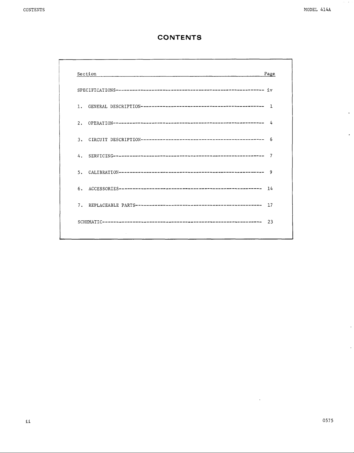
CONTENTS
CONTENTS
MODEL
414A
1.
2.
3.
4.
5.
6.
7.
1
4
6
7
9
14
17
ii
0575
Page 3
MODEL 414A
Fig.
No.
I
LLU
ST
RAT
I0
N
S
Title Page
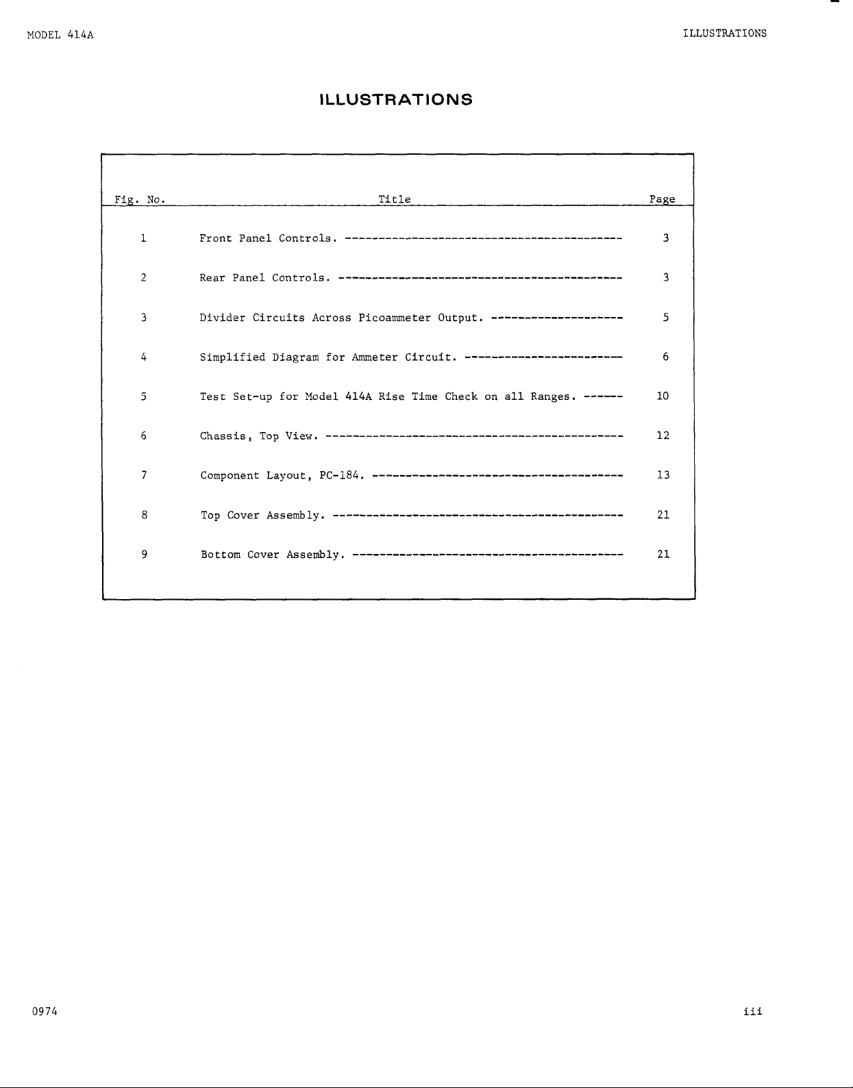
ILLUSTRATIONS
3
3
5
6
10
12
13
21
21
0974
iii
Page 4
S
PEC
IF
ICAT
ION
S
S
P
E C I
F
ICAT
MODEL
10
N
S
414A
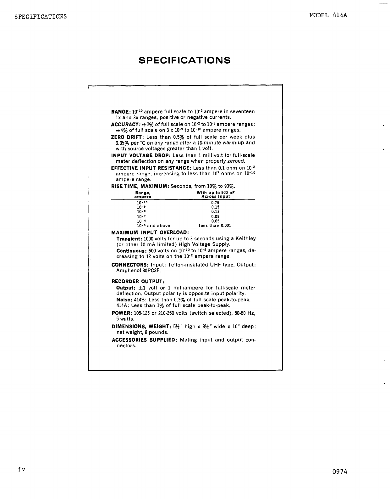
RANGE:
ACCURACY:
ZERO DRIFT:
INPUT VOLTAGE DROP:
EFFECTIVE INPUT RESISTANCE:
RISE TIME, MAXIMUM:
MAXIMUM INPUT OVERLOAD:
CONNECTORS:
RECORDER OUTPUT:
POWER:
DIMENSIONS, WEIGHT:
ACCESSORIES SUPPLIED:
10-lo ampere full scale to
lx
and
3x
ranges, positive or negative currents.
&2%
*4%
of full scale on 3 x
0.05%
per "C on any range after a 10-minute warm-up and
with source voltages greater than
meter deflection on any range when properly zeroed.
ampere range, increasing to less than
ampere range.
Range,
ampere
Transient:
(or other
Continuous:
creasing to
Amphenol 8OPC2F.
Output:
deflection. Output polarity is opposite input polarity.
Noise:
414s:
414A: Less than
105-125 or 210-250 volts (switch selected),
5
watts.
net weight,
nectors.
of full scale on
Less than 0.5% of full scale per week plus
10.10
10.9
10.8
10-7
10
-6
10.5
and
1000
volts for
10
mA
600
12
volts on the ampere range.
Input: Teflon-insulated UHF type. Output:
il
volt or 1 milliampere for full-scale meter
Less than
8
pounds.
10-9
Less than 1 millivolt for full-scale
Seconds, from
above
limited) High Voltage Supply.
volts on 10-10 to
0.3%
1%
of full scale peak-to-peak.
5%w
lo2
ampere in seventeen
lo-*
to ampere ranges;
to 10-10 ampere ranges.
1
volt.
Less than
With
less
up
to 3 seconds using a Keithley
10-6
of full scale peak-to-peak.
high
x
Mating input and output con-
0.1
ohm on
lo7
ohms on
10%
to
90%.
up
to
500
0.75
0.15
0.13
0.09
0.05
wide
Input
0.001
pF
x
Across
than
ampere ranges, de-
8%"
50-60
10"
deep:
10-lo
Hz,
iv
0974
Page 5
MODEL
414A
GENERAL DESCRIPTION
SECTION
1-1.
GENERAL.
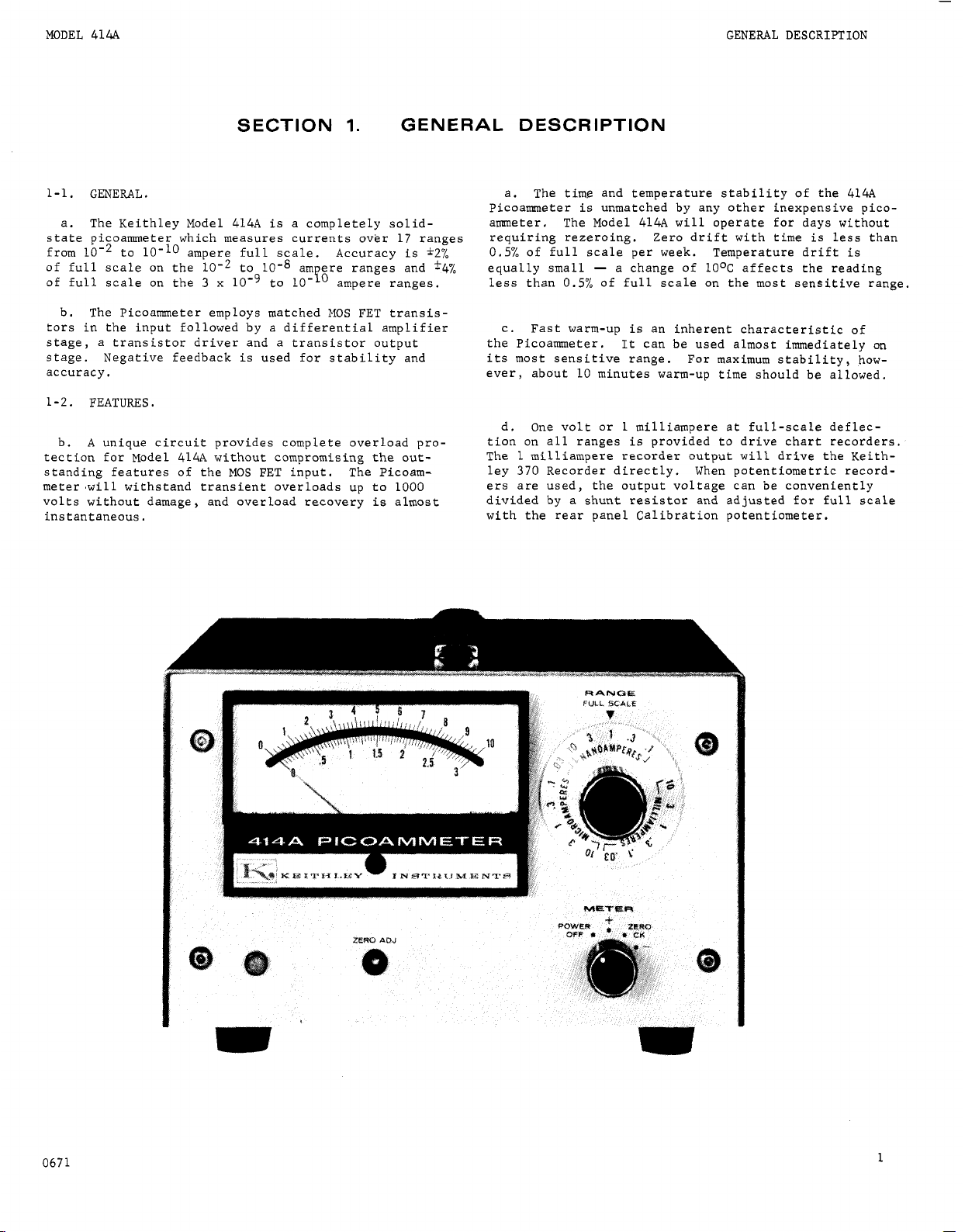
a. The Keithley Model 414A is a completely solid-
state picoammeter which measures currents over
LO-’
from
of full scale on the to
of full scale on the
b. The Picoammeter employs matched
tors in the input followed by a differential amplifier
stage, a transistor driver and a transistor output
stage. Negative feedback is used for stability and
accuracy.
1-2.
b. A unique circuit provides complete overload protection for Model 414A without compromising the outstanding features of the
meter .will withstand transient overloads up to
volts without damage, and overload recovery is almost
instantaneous.
to ampere full scale. Accuracy is
3
x
lo-’
FEATURES.
MOS
am ere ranges and
to
lo-‘’
FET input. The Picoam-
1.
ampere ranges.
MOS
GENERAL DESCRIPTION
17
ranges
*2%
FET transis-
1000
*4%
a. The time and temperature stability of the 414A
Picoammeter is unmatched by any other inexpensive picoammeter. The Model 414A will operate for days without
requiring rezeroing. Zero drift with time is less than
0.5%
of full scale per week. Temperature drift is
equally small
less than
c. Fast warm-up is an inherent characteristic of
the Picoammeter.
its most sensitive range. For maximum stability, however, about
d. One volt or
tion on all ranges is provided to drive chart recorders.
The
1
milliampere recorder output will drive the Keith-
370
ley
ers are used, the output voltage can be conveniently
divided by a shunt resistor and adjusted
with the rear panel Calibration potentiometer.
-
0.5%
Recorder directly. When potentiometric record-
a change
of full scale on the most sensitive range.
It can be used almost immediately on
10
minutes warm-up time should be allowed.
1
of
10°C
affects the reading
milliampere at full-scale deflec-
for
full scale
0671
1
Page 6
GENERAL DESCRIPTION
TABLE
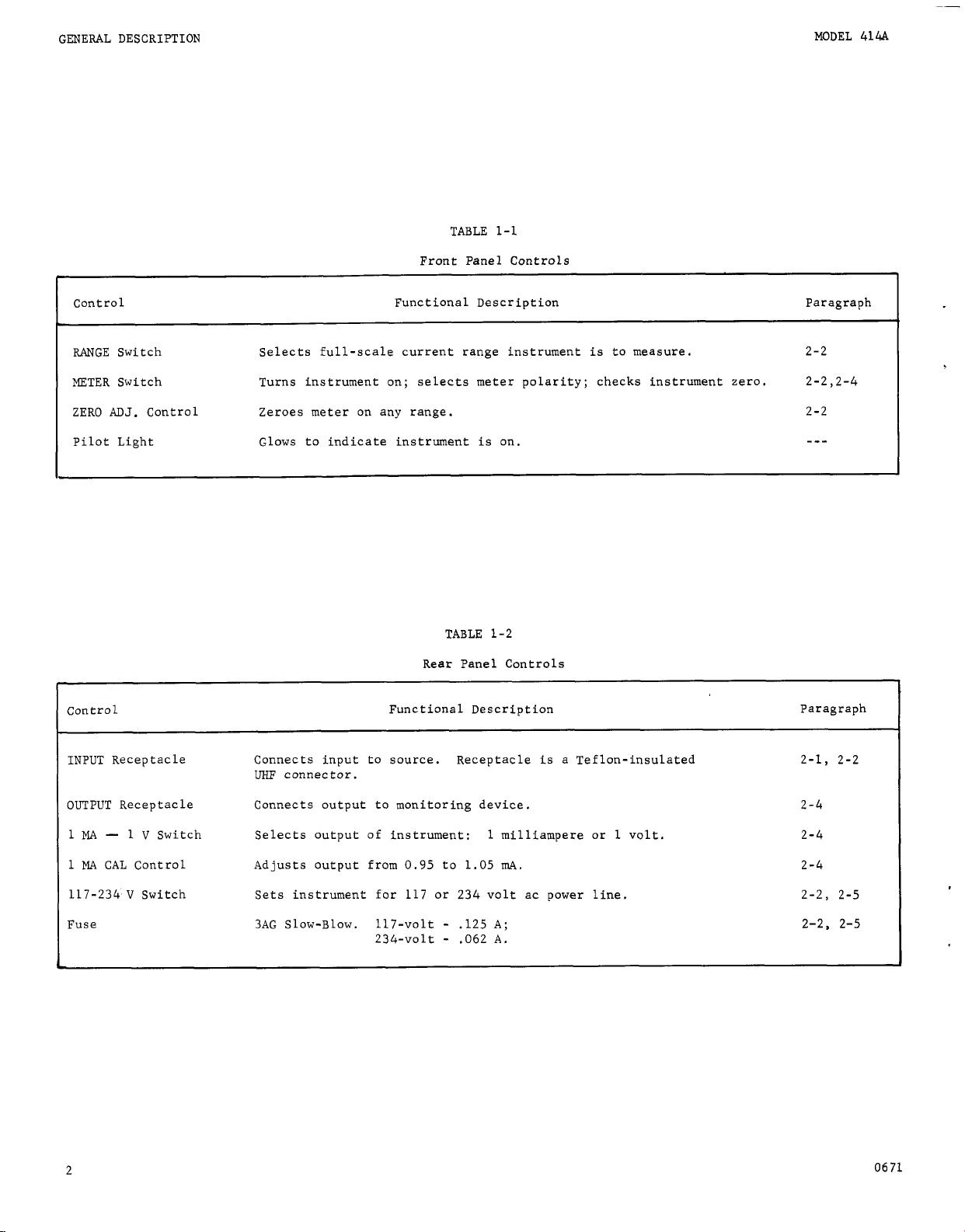
1-1
Front Panel Controls
Control Functional Description Paragraph
MODEL
414.4
RANGE Switch Selects full-scale current range instrument is to measure.
METER Switch Turns instrument on; selects meter polarity; checks instrument zero.
ZERO
ADJ.
Control Zeroes meter on any range.
Pilot Light Glows to indicate instrument is on.
TABLE
1-2
Rear Panel Controls
Control Functional Description Paragraph
INPUT Receptacle Connects input to source. Receptacle
UHF
connector.
is
a Teflon-insulated
2-2
2-2,2-4
2-2
---
2-1, 2-2
OUTPUT Receptacle Connects output to monitoring device.
1
MA
-
1
V
1
MA
CAL Control Adjusts output from
117-234
I
Fuse
2
V
Switch
Switch
Selects output
Sets instrument for
3AG Slow-Blow.
of
instrument: 1 milliampere or 1 volt.
117-volt
234-volt - .062
0.95
117
to
or
-
1.05
mA.
234
volt ac power line.
.125
A;
A.
2-4
2-4
2-4
2-2, 2-5
2-2.
2-5
0671
Page 7
MODEL
414A
METER
MlOl
-
GENERAL
RANGE
SWITCH
s102
DESCRIPTION
METER
ZERO
'I-
POWER
LAMP
DS201
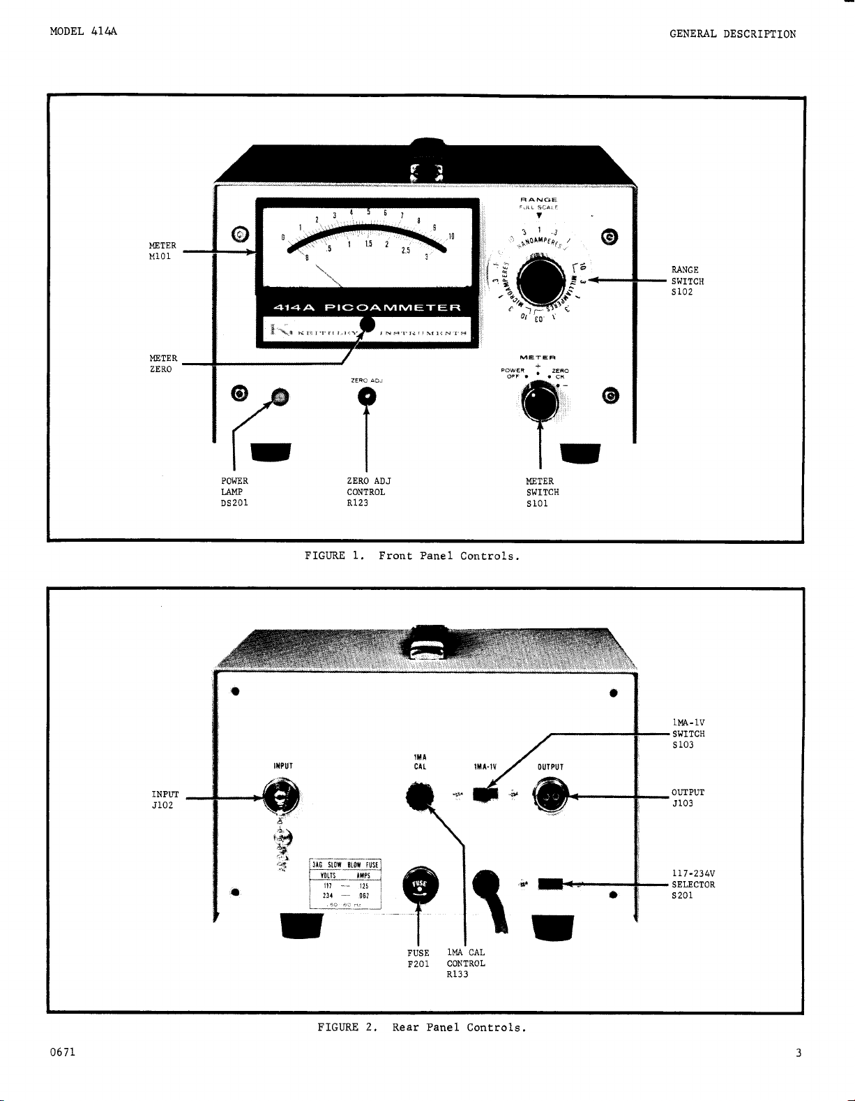
FIGURE
t
I
ADJ
ZERO
CONTROL
R123
1.
Front Panel Controls.
METER
METER
SWITCH
SlOl
\
1
SWITCH
S
103
0671
INPUT
5102
FIGURE
F~SE
IMA'CAL
F201 CONTROL
R133
-
2.
Rear Panel Controls.
OUTPUT
5103
-
117-234V
SELECTOR
s201
3
U'
Page 8
MODEL
414A
0
PE
RAT
ION
PICOAMMETER
SECTION
2-1.
INPUT CONNECTIONS. Use the following precautions
when using the Picoammeter on the more sensitive ranges.
a. The INPUT Receptacle of the Model 414A
lon-insulated
the high impedance terminal, and the outer shield
case ground.
b. Carefully shield the input connection and the current source being measured, since power line frequencies
are well within the pass band of the Picoammeter on all
ranges. Unless shielding is thorough, pickup may cause
definite meter disturbances.
c. Use high resistance, low-loss materials
as polyethylene, polystyrene or Teflon
tion. The insulation resistance of test leads and fixtures should be several orders of magnitude higher than
the source resistance. Excessive leakage
accuracy. Any coaxial cable used should be a lownoise type which employs a graphite coating between the
dielectric and the surrounding shield braid.
d. Any change in the capacitance of the measuring
circuit to ground
ing, especially on the more sensitive ranges. Make the
measuring setup as rigid as possible, and tie
necting cables to prevent their movement. If a contin-
uous vibration
as a sinusoidal signal and other precautions may be
necessary to isolate the instrument and the connecting
cable from the vibration.
UHF
connector. The center terminal
will
cause disturbances in the read-
is
present,
it
may appear at the output
NOTE
is
-
for insula-
will
a Tef-
-
such
reduce
down
2.
is
is
con-
OPERATION
1.
When the
etc. positions, use the upper meter scale. Full
scale current range
ting.
2.
When the
etc. positions, use the lower meter scale.
scale current range is equal to the
setting
2-3, MEASUREMENT CONSIDERATIONS.
a. The Picoammeter employs the fast method
rent measurement
the amplifier input and output in the feedback loop.
This method largely neutralizes the effect of input
capacity and greatly increases the response speed.
Also, the input voltage drop
of one millivolt on any range.
b. Rise time varies with the current range and the
input capacity (see specifications, Table
time, though,
across the input; however,
Picoammeter nearer the current source than to the data
reading instrument, Transmitting the input signal
through long cables
of capacitance
noise.
c. The internal resistance
should not be less than the reciprocal of the current
range being used, otherwise the zero stability
affected. The instrument
ever, but the stability
amount given by equation
Stability = 0.5%/week x (R, + Rf)/Rs
.
RANGE
Switch is set to
is
equal to the
RANGE
Switch
-
the measuring resistor
is
not affected with up to 500 picofarads
-
-
with greater than
will
increase response time and meter
is
set to 3,
is
reduced to a maximum
it
is better to place the
of
the unknown source
will
will
still be operable, how-
be degraded by the
1.
10,
RANGE
RANGE
1).
500
Equation
1,
0.1,
Switch set-
0.3,
Full
Switch
of
is
between
The rise
picofarads
will
0.03,
cur-
be
1.
Keep the shield cap on the INPUT Receptacle
when the Picoarmneter
2-2.
OPERATING PROCEDURES.
a. Check the fuse and the 117-2341 V Switch for the
proper line voltage.
b. Connect the power cord to the power source.
+
RANGE
(+).
Within seconds the meter needle should
RANGE
METER
or
Switch to the polarity of the input
-.
Increase sensitivity with the
c. Set the
S
itch to
read zero. Zero the meter with the
After a few moments increase the current sensitivity b
advancing the
ampere range. Continue zeroing with the
trol. The instrument
d. If long term measurements are to be made, allow
the instrument to warm up for at least
e. Attach the current source to the INPUT Receptacle
and turn the
signal,
Switch until the greatest
is
not in a circuit.
Switch to ampere, the
ZERO
Switch in decade steps to the
is
now ready to use.
10
on
scale deflection is achieved.
ADJ.
Control.
ZERO
ADJ
minutes.
METER
RANGE
10-
Con-
4
where
Rf
is the feedback resistance in ohms;
Rs
is
the source resistance in ohms.
For example, if the source to be measured has a resis-
tance of
back resistor
gain of the Picoammeter
stability of .5%/week
the offset due to temperature
.5%/OC. This is the reason that
have the source resistance at least equal to the feed-
back resistor.
18
d. Overload Protection.
complete overload protection for the Model 414A without compromising the features of the MOS
Recovery
meter can withstand overloads of up to
for
volts without damage.
is
105
ohms and the current is
will
be
106
ohms. This means that the
is
106/105
will
be
.5%
will
A
unique circuit provides
is
instantaneous for most overloads.
1.
At
the ampere range and below the Picoam-
3
seconds and continuous overloads of up to
2.
Above amperes, the max. continuous overload
a function of rated power dissapation in the resistor.
lom6
=
10.
X
10 = 5%/week, and
be .05%
it
is
advantageous to
FET
1000
then the feed-
Then the zero
X
lo.=
input.
volts
600
0671
Page 9
MODEL 414A OPERATION
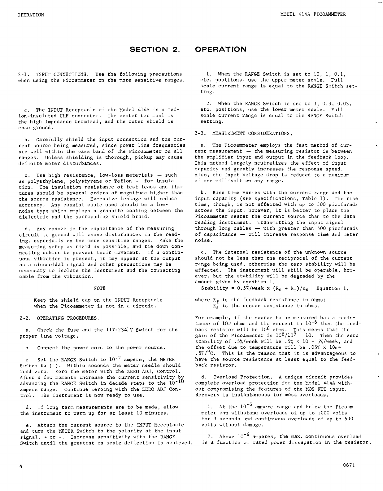
TABLE
Allowable Overloads on Ranges Above 10-6 Ampere.
4.
Range Voltage Overload Current Overload
10-5
A
10-4 A
10-3
A
10-2 A
I
3. For maximum protection, use a Keithley Model
240A Voltage Supply, or some other
current limited supply, in combination with the
Picoammeter.
2-4. RECORDER OUTPUTS.
a. For recording with the Model 414A, use the Keithley Model 370 Recorder for ease, economy, versatility
and performance. The Model 370 is a pen recorder with
10
chart speeds and
put cable has a connector which mates directly with
the OUTPUT Connector
interface problems often encountered between a measuring instrument and a recorder. The Picoammeter output,
when set to the
preamplifier is needed.
b.
Other recorders, oscilloscopes and similar in-
struments can be used with the Model 414A. The Pico-
ammeter has two outputs,
to amplify signals for recorders, oscilloscopes and
similar instruments. These can be used on all ranges.
Max. Continuous Max. Continuous
300 V
120
v
30 V
v
12
1%
linearity. The Model 370's in-
on
the Picoammeter; this avoids
1
mA
position, will drive the 370; no
No
special wiring is required.
21
volt and
1mA
4mA
10
mA
40
mA
10
milliampere
21
milliampere,
I
J
$
1
1
Mode
414A
output
(5103)
FIGURE 3.
for Driving
d. 1-Milliampere Output. Connect 1-milliampere
instruments to the OUTPUT Receptacle. Pin no,
the high terminal. Set the
The output is approximately 1 milliampere for full-
scale meter deflection on any range.
apply a known full scale signal to the Picoammeter and
adjust the
full scale. Check the recorder and meter zero and
repeat adjustment if necessary. The METER Switch does
not reverse the output polarity which is always oppo-
site input polarity.
e. For servo rebalance recorders, use a divider
across the Picoammeter OUTPUT Receptacle. See Figure
3. Set the OUTPUT Switch to
Control to trim the output for full-scale recorder de-
flections. Operation is the same as for current outputs.
Divider Circuits Across Picoammeter Output
50
and 100-Millivolt Recorders.
1
mA
CAL Control until the recorder reads
kR
t
1
1
mA
mA.
Recorder
-
1
V Switch to
For exact output,
Use the.1
1
mA
is
1
mA.
CAL
c. 1-Volt Output. Connect oscilloscopes and pen
recorder amplifiers to the OUTPUT Receptacle. Pin
1
is the high terminal and pin no. 2 is ground. Set
1
mA
-
1
the
is now
range. Internal resistance is approximately
Noise is less than.l% peak-to-peak of full scale. The
METER Switch does not reverse the output polarity.
Output polarity is always opposite input polarity.
V Switch
21
volt for full scale meter deflection on any
to
1
V. The Picoarmeter output
1
kilohm.
no.
2-5. 234-VOLT OPERATION. The instrument is shipped
for use with a 117-volt power source unless otherwise
ordered. To convert the Picoammeter for 234-volt
sources, use a screwdriver to change the slide switch
on
the back panel to the 234-volt position. Change
the fuse from 0.125 ampere to .062 ampere.
adjustment is necessary. To switch from 234 to 117-
volt operation, reverse the procedures.
No
other
0671
5
Page 10

CIRCUIT
DESCRIPTION
MODEL
414A
SECTION
3-1. GENERAL. The Keithley Model 414A
amplifier with a full scale sensitivity of either
3 volts.
sistors are selected to make measurements over a total
17
of
22223D for circuit designations.)
3-2.
a. The amplifier has matched insulated-gate fieldeffect input transistors followed by a differential
transistor stage, a transistor amplifier and a transistor output stage. Figure
circuit for the Picoammeter.
By
using the front panel controls, shunt re-
current ranges. (Refer to schematic diagram
AMMETER
OPERATION.
4
shows the simplified
3.
is
a linear dc
CIRCUIT DESCRIPTION
1
or
3-3.
AMMETER
a. Two balanced insulated-gate field-effect tran-
sistors, ~101 and Q102, are used for the amplifier input. Resistors
21850B (see schematic) protect the gate of transistor
QlOl,
the active field-effect transistor, from overloads.
The gate of Q102
Turning the METER Switch to
b.
places a short from the input to the output and zeroes
the instrument.
c.
A
4104,
and
in
which
sistor
Control, R120, varies the source voltage of transistor
Q101
Control, R123, varies the drain voltage of transistor
QlOl
current through transistors
the source bias.
4106.
d. Two zero controls are used. The Coarse Zero
with respect to transistor Q102. The
with respect to transistor Q102.
e. The
CIRCUIT.
R117
and R118 and circuit designation
is
returned to amplifier ground,
ZERO
CK
position
differential amplifier stage, transistors Q103
drives an amplifier stage, transistor Ql05,
turn drives the output
DC
Bal Potentiometer,
emitter
Rl19,
QlOl
and
follower, tran-
ZERO
ADJ
sets the drain
Q102
by varying
FIGURE 4. Simplified Diagram for heter Circuit.
it
is
b. If
is
ein,
flows through the measuring resistor,
But the output voltage,
voltage times the amplifier gain.
Therefore, from equations
From whence,
where ein/iin
negligible, then all the input current,
eo
=
=
eo
A
ein
ein/iin
assumed that the input voltage drop,
R,,
-iin
R,.
eo,
is
also equal to the input
-A
ein. Equation 3.
2
and
=
iin
R,.
=
Rs/A.
is
the effective input resistance.
3
we
Equation
get
Equation 4.
Equation 5.
iin,
and
2.
f. The voltage drop across R115 plus R116, or R116
alone, determines the full scale sensitivity of the
amplifier
and 3 x
put causes a
R115 and R116. The meter
volt output. Resistors R130 and R131 set the meter
current.
g. The full scale current sensitivity is determined
by the range resistors
with resistors R115 and R116. The current measuring
resistor
figuration increases the response speed by minimizing
the effects of input capacity.
input voltage drop to less than
h. The
milliampere flowing through resistor R135. In the
milliampere output mode an external load
for R135. Potentiometer R133 varies the current to the
external load.
3-4.
negative supplies, which provide power to the ampli
fier and output,
a. +25 and
secondary of transformer T201 is rectified by diodes
D201 and D203 and filtered by capacitor C201 to provide
+25 volts for the output. Zener diode, D205, is used
to provide a regulated
-
either 3 volts from through 3 x
lom9
and
ranges. Applying a full scale signal to the in-
is
1
~xLO-~O
1
milliampere current to flow through
connected in the feedback loop. This con-
volt recorder output
or 1 volt on
is
connected across the 3-
RlOl
through R114 in combination
It
also reduces the
1
millivolt.
is
derived from
lom9
and
1
1
is
substituted
POWER
SUPPLIES, The Model 414A has positive and
+ll
volt supply. The power supplied from
+11
volts for the amplifier.
Thus, the input voltage drop
1/A,
tion,
put resistance
6
of the output voltage, and the effective in-
is
1/A
of the measuring resistor.
is
kept at a small frac-
b. -25 and
D202 and D204, capacitor C202 and zener D206 to perform the same functions as the positive supply.
-11
volt supply. This supply uses diodes
0671
Page 11

-
MODEL 414A
SECTION
4-1.
GENERAL.
troubleshooting procedures for the Model 414.4 Picoam-
meter. Follow these procedures
to maintain the performance of the instrument.
4-2.
SERVICING SCHEDULE. The value of the high-megohm
resistors,
ly every six months for specified accuracy, Except for
this the Model
beyond the normal care required of high-quality elec-
tronic equipment.
4-3.
PARTS REPLACEMENT.
a. The Replaceable Parts
the electrical components of the Picoammeter. Replace
components only as necessary. Use only reliable replacements which meet the specifications.
b. The MOS FET input transistors,
specially selected and matched; order only as a plug-
in unit, part number
Inc.
4-4. TROUBLESHOOTING.
a. The Procedures which follow give instructions for
repairing troubles which might occur in Model
Use the procedures outlined and use only specified
Section 4 contains the maintenance and
as
closely as possible
R113
and R114, should be checked approximate-
414A
requires no periodic maintenance
List
in Section 7.describes
Q101
and
23733
,
from Keithley Instruments,
Q102,
414.4.
4.
are
SERVICING
SERVICING
replacement
ded for troubleshooting. If the trouble cannot be
readily located or repaired, contact Keithley Instru-
ments, Inc., or
b. Table
might occur. If the repairs indicated in the table
do not clear up the trouble, find the difficulty
through a circuit-by-circuit check, such as given in
paragraph 4-5. Refer to circuit description in Sec-
3
tion
determine their function in the circuit. The complete
circuit schematic,
4-5.
a. If the instrument
power supplies. The typical voltage values, given
on the schematic, are referenced to chassis ground.
Zero the Model
a Model
b.
with the
this occurs, adjust the front panel
or, if necessary, the Coarse Zero Potentiometer,
located on the PC board. If this does not work, inspect all PC boards for a possible break in the
If these appear all right proceed with step c.
parts.
6
to find the more critical components and to
PROCEDURES TO
Table 5 lists
its
representative.
contains the more common troubles which
22223D,
GUIDE
414A
meter and make measurements with
is
TROUBLESHOOTING.
will
equipment recommen-
in Section
not operate, check the
7.
153.
At
times, the meter
METER
Switch in the
will
ZERO
not zero
CK
position, If
ZERO
on
any range
ADJ
Control
~20,
tapes.
Equipment Recommended for Mode1414A Troubleshooting and Calibration. Use these instruments or their equivalents.
Instruments Use
163
Keithley Model
reading,
Hewlett Packard
Keithley Instruments Model
10
racy, float
Keithley Instruments Model
10-14
Keithley Instruments Model
Keithley Instruments Model515AMegohm Bridge.
Keithley Instruments Model
Voltmeter;
Shielded resistors of different values, and shielded Rise time check.
50 pF and 500 pF polystyrene capacitors.
Tektronix Model
pV to
to
10
megohm input resistance.
1000
t500
10-4
100
Digital Voltmeter,
202A
Function Generator Rise
V,
200
MR
input resistance,
volts off ground.
ampere.
pV
to
500
V,
561A
Oscilloscope Noise and
153
Microvolt-Ammeter, General circuit checking.
261
Picoampere Source; Source to calibrate current.
370
Recorder Monitor drift.
662
Guarded Differential Calibrate meter zero.
*O.Ol%.
20.1%
*l'X
TABLE 5.
of General calibration.
time
check.
accu-
Verify high megohm resistors in Range Switch.
rise
time check.
0177
7
Page 12

SERVICING
MODEL 414A
TABLE
I
I
I
I
Difficulty
Excessive zero offset
Excessive offset current
Cannot zero on any range
Meter off scale on one of Faulty range resistor
range settings
One of ranges out of
soecif ication
c. Amplifier.
1.
To
back loop by removing Q106, D102, D105 and R129 from
the
Model WV98C, used as an ohmmeter, for shorts.
2.
and Q104. Adjust Coarse Zero Potentiometer, R120,
and front panel
be difficult to reach a steady null; however,
sufficient
smooth manner). If this
and Ql04 from the circuit and repeat the same process.
If null can now be reached, replace 4103 and Q104.
check the amplifier, disconnect the feed-
PC
board. Check diodes D102 and D105 with the
Connect a Model 153 between the bases of 4103
ZERO
to
be able to swing through zero in a
I
I
Input transistors m$y be defective
I
Power supply voltage low Check power supply
Excessive temperature fluctuations Check
or defective input transistors
Refer to paragraph 4-5. Refer to paragraph 4-5.
I
Defective range resistor Check resistor; replace if faulty.
ADJ
Control for a null (it may
is
not possible, remove Q103
6. Model 414A Troubleshooting,
Probable Cause
it
is
I
I
Check
QlOl
QlOl
Check resistor; replace if faulty
So
1
ut i on
and 4102; replace if faulty.
and QlO2; replace if faul
I
I
I
If
it
cannot be reached,
3. Check the next stage, 0105, by placing a Model
153 from the collector end of R128 to ground. Adjust the Model 414A Zero Controls for a null. If
this cannot be accomplished, check
ble open by shorting
can now be reached,
placed. If null cannot be reached, replace Ql05.
4. If null can now be attained at the collector
Ql05,
of
Q106 should be replaced. If this does not cure the
trouble, carefully check all the diodes associated
with the output stage
the trouble
QlOl
and Q102 are faulty.
DlOl
it
with a clip lead. If null
DlOl
is open and should be re-
is
in the output stage and
-
D102, D103, D104 and D105.
for a possi-
8
0671
Page 13

MODEL 414A
CALIBRATION
SECTION
5-1. GENERAL.
a. The following procedures are recommended for cali-
brating the Model 414A. Use the equipment recommended
in Table 5. If proper facilities are not available or
if difficulty is encountered, contact Keithley Instru-
ments, Inc., or its representatives to arrange for fac-
tory calibration.
b. If the Model 414A is not within specifications
after the calibration, follow the troubleshooting procedures or contact Keithley Instruments, Inc., or its
representatives.
5-2.
PRELIMINARY PROCEDURES.
a. Make sure the
on the rear panel are set to 1V and 117V respectively.
Set the Front Panel Controls as follows:
RANGE
Switch
METER Switch POWER OFF
ZERO ADJ. Control Mid-range.
b. Set the DC Bal Potentiometer, R119, Coarse Zero
Potentiometer, R120, and Meter Cal. Potentiometer,
R131, near mid-range.
c. Zero the meter with the Mechanical Zero Control.
d. Plug the Model 414A into a 117 volt source and
set the METER Switch to ZERO CK.
1.
If the Model 414A is operative, then the meter
should read
Adjust the Coarse Zero Potentiometer for a zero
dication on the meter.
2. If the Coarse Zero Potentiometer, R120, can
not zero the meter, check for a shorted heat sink
on the MOS
halves of the heat sink must
for the Coarse Zero potentiometer to function properly.
The Table lists all internal controls, the figure pic-
turing the location and the paragraph describing the
adjustment.
I
Control Desig. Ref. Paragraph
I
DC Bal. RL19 7 5-2,
Coarse Zero R120 7 5-2,
Meter Cal
FET
TABLE
~~
1
MA
-
1
V and 117-234 V Switches
10
MILLIAMPERES
on
scale for either polarity
transistors,
7.
Model 414A Internal Controls
Circuit Fig. Refer to
R131 7 5-2,
Q101
and Q102. The two
be
insulated
i
(+
in
5.
or
-7..
in-
order
5-4
5-4
5-6
CALIBRATION
I
5-3. POWER SUPPLY CHECK. (See Figure 7 for test
points for the Power Supplies.)
a. Check the positive and then the negative 25 volt
supply by connecting the Model
C201 and C202 respectively (Figure
should be plus and minus 25 volts
The ripple in each case should be less than 3 volts
peak-to-peak.
For all these power supply checks make sure
the Model
and the test points (Figure,7).
b. Check the positive and then the negative
supply by connecting the Model 7050 across Resistors
R202 and R205 respectively. The voltage for the plus
and minus
11
volts
case should be less than 30 mV peak-to-peak.
c. Monitor the plus and minus 11 volt supplies as
the line voltage is changed from 105 volts ac to 125
volts ac. The voltage change of the plus and minus
volt supplies should be less than k0.15 volt. Observe
the zener noise on the ripple. If the noise exceeds
5mV peak-to-peak, or if large random spikes are observed replace the zener
and D206 for the minus
d. Turn the Model 414A off and prepare the Picoam-
meter for 234 volt,
414A into a 220 volt ac, 50 cycle line and check the
positive and negative 25 volt supplies per paragraph
5-3a above. The same readings as in subparagraph a
above should be obtained except that an additional
volt tolerance should be allowed for each
ference between 234 volts ac and the actual line voltage
The remaining calibration procedures should
all be performed with the Model 414A operating from 117 volts ac,
5-4. MOS FET CURRENT ADJUST.
a. Set the Picoammeter RANGE Switch to
ERES and the METER Switch to ZERO CK.
b. Set the front panel ZERO ADJ. Control to approx-
imately mid-range and adjust the Coarse Zero Potenti-
ometer, R120, for a zero indication on the meter.
c. Connect the Model 7050
and adjust the DC BAL Potentiometer, R119, for an indication of -5.4 volts f0.2 volt.
7050
is connected between ground
11
volt supplies should be plus and minus
fl.10
volts respectively. The ripple in each
11
50
Hz
7050
across capacitors
7).
The voltage
*2
volts respectively.
NOTE
11
(D205
for the plus
volt supply).
operation. Plug the Model
NOTE
60
Hz.
DVM
across resistor R122
11
volt
10
volt dif-
10
MILLIAMP-
volt
11
1
0671
9
Page 14

-
CALIBRATION
5-5.
OFFSET
a. To check the offset:
1.
AMPERES and the
INPUT Receptacle and connect the Model 414A to the
Model
When checking the-offset noise, make sure
the Model 414A cover is on.
2.
for zero volts at the output.
3. Set the
sure that the output remains at zero volts, adjust-
ing the front panel
4.
remain within
b. To check the noise:
AND
NOISE CHECKS.
Set the Picoammeter
7050
If necessary, adjust the
METER
DVM.
RANGE
Set the METER Switch to
*10
millivolts.
RANGE
Switch to
NOTE
Switch to
ZERO
ADJ.
Switch to
ZERO
ZERO
.1
NANOAMPERES.
Control if necessary.
+.
The output should
CK.
ADJ.
10
Cap the
Control
MILLI-
Make
MODEL
b Set the Model 414A METER Switch to + and apply
lo-&
ampere with the Model
the
ZERO
ADJ.
output.
c. Adjust the Meter Cal Potentiometer, R131, for
full scale meter deflection.
d. Load the Model 414A output with a
sistor and set the
e. Adjust the rear panel
that the output voltage can be adjusted at least
volt either side of
f. Remove the
Switch to
g. Set the METER Switch to
output if necessary.
Control for exactly
1
1.5
1.5
1
V.
261.
If necessary, adjust
1.000
volt at the
1.5
V
-
1
MA
Switch to
1
MA
CAL
volts.
kilohm load and set the
ZERO
1
MA.
Control and note
CK
and re-zero the
kilohm re-
1V
414A
0.1
-
1MA
1.
Connect the Model 414A
561A
the Model
2.
Set the
voltage from
put noise should be less than
peak on all ranges. High noise is usually indica-
tive of faulty Zener Diodes
5-6.
METER
a. Set the
the Model
PUT
OUTPUT
261
Receptacle and connect the Model 7050
Receptacle.
Oscilloscope.
METER
105
AND
RANGE
Picoampere Source to the Model 414A
Switch to + and vary the line
volts ac to
1MA
OUTPUT CALIBRATION.
Switch to 1 MICROAMPERE, Connect
OUTPUT
125
D205
Receptacle to
volts ac. The out-
10
millivolts peak-to-
and
D206.
DVM
to the
IN-
5-7.
RANGE
ACCURACY
a. Connect the Model 414A INPUT Receptacle to the
261.
Model
DVM.
7050
b. Check the full-scale accuracy of all positions
the
RANGE
puts to ensure proper operation of both polarities at
various current input levels. Check the accuracy of
10
the
to
f2%
livolts). Check the accuracy of the 3
through the
at the output
Connect the OUTPUT Receptacle to the Model
Switch. Check both positive and regative
MILLIAMPERES
of full scale at the output
.1
(1.0
CHECK.
through the
NANOAMPERES ranges to
volt *40 millivolts).
10
NANOAMPERES ranges
(1.0
volt
NANOAMF’ERES
i.4
of full scale
*20
mil-
or
in-
5.
Test
FIGURE
tors or capacitor, UHF-Tee and the Shunt Capacitor.
10
Set-up for Model 414A Rise Time Check on all ranges. Be sure to properly shield the series resis-
0671
Page 15

MODEL
414A
5-8.
RISE
TIME
Model 414A requires two different test set-ups. The
first set-up
MILLIAMPERES through
set-up is for checking the rise times on the ranges
NANOAMPERES
a.
1
the test fixture as illustrated in Figure 5.
TABLE
ERES through
the Model 414A
Generator frequency settings, the series resistor used
for each
able rise time.
RANGE
1
.1
10
1
.1
10
MILLIAMPERE through
1.
Equipment used (Refer to Table 5): The Model
202A Function Generator, six shielded resistors ranging in value from 3 kilohms to
UHF
8), a
capacitor, the Model 414A and the Model 561A Oscilloscope. The oscilloscope used must be dc coupled.
8.
Model 414A Generator Maximum
Switch Series Frequency Rise Time
Setting Resistors
MILLIAMPERES
MILLIAMPERES
MICROAMPERES 300 kR
MICROAMPERES 3
MICROAMPERES
NANOAMPERES 300
2.
Procedures
CHECK. To check the rise time of the
is
for checking the rise tLmes on the
10
NANOAMPERES ranges. The second
and below.
10
NANOAMPERE ranges. Set
300
Tee connector, a 500 pF polystyrene shunt
Model 414A Rise Time Check for 1 MILLIAMP-
10
NANOAMPERES Ranges. The Table gives
RANGE
Switch settings, the Function
RANGE
Switch setting, and the maximum allow-
Function
(Hz)
250 less than
kR
3
30
MR
30
MR
:
250 less than
kR
250 less than
Ma
megohms (See Table
(milliseconds)
2.5
2.5 90
2.5
50
130
CALIBRATION
2.
Procedures:
1
1
I
t
1
1
1
ERE
Using the shunt increases the sensitivity
a) Apply a triangular wave from the Model'202A
across the capacitor, through the
Model 414A INPUT Receptacle. Monitor the Model
414A output with the Model 561A. Use the proper
Model 2.02A frequency setting as indicated in Table
b) Adjust the Model 202A amplitude control as
needed to obtain
414A output. Check the
figures shown in Table 9.
TABLE
9. Model 414A Rise Time Check for
and
.1
NANOAMPERES Ranges. The Table gives the Model
RANGE
414A
quency settings, and the maximum allowable rise time.
Model 414A Function Generator
RANGE
Setting
1
NANOAMPERES
.I
NANOAMPERES 0.25
5-9. DRIFT VERIFICATION.
a. Shunt the Input of the Model 414A with a 10-kil-
ohm resistor with the
and the
While doing the drift run make sure the
Model 414A cover is on.
Switch settings, the Function Generator fre-
Switch
METER
2
volts peak-to-peak at the Model
10 - 90% rise time to the
Frequency Rise Time
(Hz)
1.0
RANGE
Switch set to t or
Switch set to 1 MICROAMP-
NOTE
UHF
Tee to the
1
NANOAMPERES
Maximum
(milliseconds)
150
750
-,
as necessary.
100
times.
9.
I
a)
Apply
fixture
a square wave from the Model 202A
UHF
Tee to the Model 414A
2
volts peak-to-peak at the Model
10 - 90% rise time to the
.I
UP
NANOAMPERES ranges. Set
as illustrated in Figure 5, except
IN-
Function Generator across the selected series re-
sistor, through the
PUT
Receptacle. Observe the output of the Model
414A with the Model 5628
b) For each Model 414A range, use the Model 202A
frequency setting and the series resistor indi-
cated in Table 8.
c) Adjust the Model 202A amplitude control as
needed to obtain
414A output. Check the
figures shown in Table 8.
b.
1
this
that a shielded 50 pF polystyrene capacitor should be
substituted for the series resistors between the
Function Generator and the UHF Tee.
equipment of the previous set-up with the exception
of the 50 pF polystyrene capacitor. The capacitor in
this set-up serves a similar function as the series
resistors in the previous test set-up.
NANOAMPERE and
test
1.
Equipment Used: This test set-up uses the same
b. Connect the Model 370 Recorder to the Model 414A.
Set the Recorder attenuator to
drift full scale) or 0.3 volts
c. Set the METER Switch to
Control for near zero volts output. The
trol is very sensitive with the sensitivity increased
100
times. Set the METER Switch to - if the drift is
negative.
d. After a 10-minute warm-up, the Model 414A may
drift 700 microxolts per 24 hours plus or minus 500
microvolts per
e. In some cases, the 24-hour drift may appear marginal or
to a steep drift slope during the early part of the
drift. If this
the drift for an additional 24 hours and calculate a
weeks drift as follows:
times 6 and add the drift noted during the first 24-
hour period.
it
1.
Multiply the drift during second 24-hour period
2.
Total drift must add up to 5
C
change in temperature.
may be slightly out of specification due
is
so,
it
1
volt
(10
(3
mV
+
and adjust the
may be desired to continue
millivolts
full scale).
ZERO
ZERO
ADJ
mV
or less.
Con-
ADJ
0671
11
Page 16

CALI
BRATI
ON
MODEL 414A
12
FIGURE
6.
Chassis,
Top
View.
Page 17

bo
c
Page 18

ACCESSORIES
MODEL
414
SECTION
6-1.
GENERAL. The following Keithley accessories 6-2. OPERATING
can be used with the Model 414A to provide additional
convenience and versatility. operating information.
Model 6106 Electrometer Connection
Description
The Model 6106 contains a group
leads and adpaters for low current measurements.
components are housed in a rugged carrying case with Cable,
individual compartments. Cable, 24",
:
of
the most useful Description No. Part No.
6.
All
ACCESSORIES
INSTRUCTIONS.
is
Manual
Parts
Connector, UHF to
Adaptor, UHF
Adaptor, UHF
Adaptor Tee, UHF to UHF 6
Adaptor, Binding Post
The two cables (Items 1 and 2) are coaxial shie
leads useful for connections where low noise
tial. The 24" cable (Item
nect two instruments having
cable (Item
under test through the use of clip leads.
post adapter gives easy access to the electrometer
"high" terminal. Two
permit cables to be connected together.
connector simplifies galvanometric current measurements
when using a current source and electrometer or picoammeter. Adapters (Items 4 and
version from
supplied with each accessory giving complete
Kit
List:
30",
UHF to clips
UHF
to UHF
UHF
to
BNC
to
BNC
1)
can be used to connect to the circuit
UHF
to
A
separate Instruction
Item Keithley
2)
can be used to intercon-
UHF
receptacles.
UHF
female couplers (Item
5)
BNC
terminations.
1
2
3
4
5
7
are useful for con-
The
19072C
18265C
cs-5
cs
-
cs
-
cs-
190
is
The
A
binding
UHF
15
72
71
1B
ded
essen-
30"
3)
"tee"
Model 261 Picoampere Source
Description:
261
is
The Model
3
with
ampere to
eight decade ranges. Accuracy
-
+1.6% exclusive of input drop considerations.
A
The Model 261
brating picoammeters and electrometers.
used as an accurate current source for zero suppression
and for galvanometric measurements.
14
digit resolution. The output ranges are
1.1
p
p
1
ica t ion
an accurate picoampere current source
x
10-4 ampere, positive or negative, in
:
is
a secondary standard for use in cali-
is
rated from 2.25% to
It
can also be
0671
Page 19

-
MODEL 414A
Model 4003A Rack Mounting Kit
Description: Parts List.:
The Model 4003A is a rack mounting kit with overall Item Qty. Per Keithley
dimensions, 5-1/4 inches high x 19 inches wide. Two
top covers are provided for use with either
13 inch deep instruments. 2 Panel Adapter Plate
Application
The Model 4003A converts the instrument from bench
mounting to rack mounting. It is suitable for mount-
ing one instrument in one-half of a standard 19-inch
rack.
:
10
inch or
No.
1
3
4
5 Connectinn Plate
6
7
8
Description Assembly
Top Cover,
Angle Support
Screw,#10 x 3/8"
Screw,
Angle
Top Cover, 13"
10"
+/16
x
1/21!
1
1 17452B
1
4
1 19126A
4
1 14624B
1
ACCESSORIES
No.
Part
18554B
174768
---
---
20015B
4004.4
Model
Description: Parts List:
The Model 4004A is a rack mounting kit with overall
dimensions, 5-1/4 inches high
top covers are provided for use with either
or
13
inch deep instruments.
Application
The Model 4004A converts the instrument from bench
mounting to rack mounting. It is suitable for mount-
ing two instruments in a standard 19-inch rack.
0671
:
x
19 inches wide.
10
Dual Rack Mounting Kit
Item
Two
inch
No.
1
4
5 Connecting Plate
6
7
8
9 Zee Bracket
10
Top Cover,
Screw,
Screw,
Angle 2
Top Cover, 13"
Plate (not shown)
Qty. Per Ke it hle y
Description Assembly Part
#lo
#lo
10"
x
x
1/2
1/2
2 18554B
8
1 19126A
4
2 20015B
1
1
---
---
14624B
19144A
17451rA
No.
15
Page 20

ACCESSORIES
MODEL 414
~
Models 240A,*244, 245, 246 Voltage Supplies
Description:
Keithley voltage supplies are highly-stable, low-noise
power supplies for voltages up to 23100 volts dc.
Application
:
Keithley voltage supplies are commonly used with pico-
of
ammeters in the measurement
resistance, light levels
(photomultipliers), and radiation intensity (ion chambers).
These high voltage supplies have been designed to
operate with the Keithley line of electrometers,
picoammeters and resistivity accessories.
application is shown using the Model 414s
A
typical
(6r 414A)
and the Model 240A in a photomultiplier experiment.
Output Ranges
:
Model
2 40A
244 -200 to
2 45
2
46
,,/,,,a
No.
..I.
1
-
Voltage
0
to i1200v
-2200v
0
to +2100v
0
~
I
I
to ~3100V
\\
Model 4104 Electronic Trip
The Model 4104 is an electronic trip installed in the
picoammeter to provide automatic current control.
Combinations of high, low,
2
polarity, and latching
is available.
16
Model 4109 Polarizing Supply
The Model 4109 provides
+300
volts at
1
KIA
for
applications requiring a stable voltage source. The Model
4109 can be ordered installed in the picoameter if
desired.
0671
Page 21

MODEL 414A
-
REPLACEABLE PARTS
SECTION
7-1.
REPLACEABLE PARTS LIST. The Replaceable Parts
List
describes the components of the Model 414A. The
List
gives the circuit designation, the part descrip-
a
tion,
number and the Keithley Part Number. The last column
indicates the figure picturing the part. The name and
address of the manufacturers listed in the "Mfg. Code''
column are in Table 14,
7-2.
suggested manufacturer, the manufacturer's part
HOW
TO ORDER PARTS, b. Order parts through your nearest Keithley rep-
a. For parts orders, include the instrument's model Instruments, Inc.
A
CbVar Carbon Variable
CerD Ceramic, disc
Comp
DCb Deposited Carbon
EA
1
F
Ampere
C
omp
o
s
it
ion
Electrolytic, Aluminum
Farad
7.
TABLE 12. Abbreviations and Symbols.
Fig. Figure
GCb Glass Enclosed carbon
k
ii:'
REPLACEABLE PARTS
and serial number, the Keithley Part Number, the circuit designation and a description of the part.
structural parts and those parts coded for Keithley
manufacture (80164) must be ordered through Keithley
Instruments, Inc., or
ing a part not listed in the Replaceable Parts List,
completely describe the part,
locat ion.
resentative or the Sales Service Department, Keithley
kilo (lo3)
micro (10-6)
Mega (lo6)
Manufacturer
Metal Film
Mylar
its
representatives. In order-
its
R
P
Pol'y Polystyrene
Ref. Reference
V
1
W
WWVa
ohm
pic0
Volt
Watt
r
Wirewound Variable
function and
-12
(10
)
All
its
MODEL
(Refer to Schematic Diagram 22223D for circuit designations.)
Circuit Mfg. Mfg.
Desig. Value Rating Type Code Part No.
ClOl
C103 .02 pF 600
C104 .02 pF 600
C105 .0047
C106 .0022
C107 680 pF 600
C108
c109 .0033
CllO
Clll
c112 220 pF
C113 47 pF
C114 22 pF
C115
C116
c201
c202
*Nominal value
.25
pF
.1
pF
UF
pF
.01
pF 600
p.F
.0022
WF
680 pF
.02
pF
.0068
pF* 600
100
pF
100
yF
400
400
600
600
600
600
600
500
500
500
600
400
400
V
V
V
V
V
V
V
V
V
V
V
V
V
V
V
V
V
V
414A REPLACEABLE PARTS LIST
CAPACITORS
MY
My 13050 SMlA
CerD 72982 ED-. 02
CerD
CerD
CerD
CerD 72982 ED-680 C22-680P 6
CerD 72982
CerD
CerD 72982
CerD
Poly
Poly
Poly
CerD
CerD
EA
1
EAl
13050 SMlA C73-.
72982 ED-.02
72982
72982
72982
72982 ED-680
71590
71590
71590 CPR-22J
72982
72982 851-Z5U0-682M C22-.0068M
73445
73445 C43 7AR/G100
ED-.
0047 C22-.0047M 6
ED-.
0022
ED-.
01
ED-
.0033 C22-.0033M 6
ED-.
0022 C22-.0022M 6
C
PR-220
C
PR- 47
J
ED-.
02
C
43
7AR/G
J
100
Ke
i
th ley Fig.
Part
No.
25M
1M
C73-.
C22-.
02M 6
C22-.
02M 6
C22-.0022M 6
C22-. 01M 6
C
2
2 - 680P 6
Cl38-22OP 6
C138-47P 6
Cl38-22P 6
C22-. 02M 6
C
150
-
lOOM
C
150
-LOOM
Ref.
6
6 c102
7
7
7
0575
17
Page 22

REPLACEABLE PARTS
DIODES
Circuit Mfg. Keithley Fig.
Desig. Type Number Code Part No. Ref.
MODEL
-
414A
DlOl
D102
D103 Rectifier,
D104 Rectifier,
D105 Rectifier,
D106
D107
D201
D202
D203
D204
D205
D206 Zener 1N715 12954
Circuit Mfg. Ke i th 1 ey Fig.
Desig. Description Code Part No. Ref.
21850B
DS 201
F201 (117
F201 (234
5101
PlOl
V)
V)
Silicon 1N645
Zener
lA,
800V
lA,
800V 1N4006
lA,
800V
Silicon
Silicon
Silicon
Silicon
Silicon
Silicon
Zener
MOS FET Input Plug-In Card
Pilot Light, Neon (Mfg. No. 2190)
Fuse, Slow blow, 1/8
Fuse, Slow blow, 1/16
Printed Circuit Contacts (Mfg. No. 02-005-113-6-200)
Printed Circuit Contacts, mate of
005-111-5-200)
vR47
1N4006 04713 RF-38
1N4006 04713
1N645
18645
1N645
1N645
1N645
1N645
1N715
MISCELLANEOUS
A
(Mfg. Type MDL)
A
(Mfg. Type MDL)
JlOl
01295 RF-14
84970 DZ-30
04713 RF-38
01295 RF-14
01295 RF-14
01295 RF-14
01295 RF-14
01295 RF-14
01295 RF -14
12954
PARTS
(Mfg. No. 02-
RF-38
DZ-22
80164
91802
71400
71400
91662
91662
DZ-22
7
23734A 6
PL-28
FU-20
FU-21
cs-199
cs-200
2
Receptacle,
(F) Plug, UHF, mate of 5102 (Mfg. No. 83-822)
Cap (Mfg. No. 7901)
Receptacle, Microphone,
(F) Plug, Microphone, mate
Meter
A.C.
Rotary Switch,
Knob Assembly, Meter Switch
Rotary Switch less components,
Rotary Switch with components, Range
Knob Assembly, Range Switch
Slide Switch,
Slide Switch,
---
T201
(F) Furnished Accessory
Knob Assembly, Calibration Control
Trans former
UHF,
INPUT (Mfg. No. 6804)
OUTPUT
Power Cable, 6 feet (Mfg. No. 4638-13)
METER
1
MA - 1
117
V
V
-
234
(Mfg. No. 80-PC2F)
of
5103 (Mfg. No. 80-MC2M)
RANGE
(Mfg. No. G326)
V
91737
02660
91737
02660
02660
80164
93656
80164
80164
80164
80164
80164
79727
80164
80164
80164
CS-64
cs-49
CAP-4
CS-32
cs-33
ME-79
CO-5
SW-244
21660A
SW-243
21848B
21649A
-
45
SW
SW-151
16373A
TR-112
2
6
2
2
7
18
0476
Page 23

MODEL 414A
RESISTORS
Circuit Mfg. Mfg. Keithley Fig.
Desig. Value Rating Type Code Part No. Part No. Ref.
REPLACEABLE PARTS
RlOl
R102
R103
R104
R105
R106
R107
R108
R109
RllO
Rlll
R112
R113
R114
R115
R116
R117
R118A*
R119
R120
R121
R122
R123
R124
R125
R126
R127
R128
R129
R130
R
300
1
kR
3
kR
10
kR
30
kR
100
kR
300
kR
1
MR
3 M1
10
Mil
30 MR
100
Mil
R
109
loLo
2
kR
1
kR
1 Mil
100
kR
5
kR
1
kR
11.8
18
kR
2
kR
18
kR
15
kR
680
R
2.2
k9
4.7
kR
1.2
kR
2
kR
R
kR
1%,
1/2
112
1/2
1/2
1/2
1
w
1/2
1/2
1/2
1
w
2
w
1/2
114
w
5
w
112
112
112
1/2
112
112
112
2
1/2
w
w
w
w
w
w
w
w
w
w
w
w
w
w
w
1%,
1%)
1%,
1%)
1%,
1%,
1%,
1%)
1%, 112
1%,
1%,
3
%
3
Yo
1/2%, 1/2
112%, 112
1%,
lo%,
20%, 2
lo%,
1%,
1%,
20%, 0.2
1%,
lo%,
lo%,
lo%,
lo%,
lo%,
1%,
w
w
W
w
w
w
w
w
DCb
DCb
DCb
DCb
DCb
EPOXY
DCb
DCb
DCb
DCb
DCb
DCb
GCb
GCb
MtF
MtF
DCb
Comp
WWVar
WWVar
MtF
DCb
CompV
DCb
Comp
Comp
Comp
Comp
Comp
DCb
91637
91637
07716
07716
91637
91637
07716
91637
91637
07716
91637
91637
63060
63060
07716
07716
91637
01121
71450
71450
07716
07716
71450
07716
01121
01121
01121
01121
01121
07716
DCF 1/2
DCF 1/2
DCC
DCC
DCF 1/2
MMF-1
DCC
DCF 1/2
DCF 1/2
DCC
DC-1
DC-2
RX-1
RX-1
CEC
CEC
DCF 1/2
CB
-
115
1NS
AW
CEC
DCC
70
DCC
EB
EB
EB
EB
HB
DCC
R12-300
R12-1K
R12-3K
-
1
OK
R12
-
3 OK
R12
R 150
-
1
OOK
R12-300K
R12-1M
R12-3M
R12-10M
R13-30M
1
OOM
R14~20-109
R20
-
1
010
R61-2K
R61-1K
R12-1M
R76
-
1
OOK
RP50-5K
RP34-1K
R94-11.8K
R12-18K
RP31-2K
-
18K
R12
R1-15K
R1- 680
Rl-2.2K
Rl-4.7K
R3-1.2K
R12-2K
6
6
6
6
6
6
6
6
6
6
6
6
6
6
6
6
7
7
7
7
7
7
7
7
7
7
7
7
7
r
2
R131
R132
R133
R134
R135
R201
R202
R203
Circuit
Desig. Number Code Part No. Ref.
Q106 NPN, Case TO-66, 40312 02735 TG-54 7
**
Replace R118, QlOl or Q102 by ordering Plug-in Board 23733
0177
1
1
1
1
27
1
1
kR
kR
kR
kR
kR
kR
kR
kR
20%, 2
112%, 112
lo%,
112%, 112
1/2%, 112
lo%,
lo%,
lo%,
PNP, Case R-110 F-I S17638
PNP, Case R-110 F-I S17638
2N3904
w
5
w
112
1/2
1/2
w
w
w
w
w
w
WWVa
MtF
WWVar
MtF
MtF
Comp
Comp
Comp
TRANS1 STORS
Mfg.
80164
80164
04713
71450
07716
71450
07716
07716
01121
01121
01121
1NS
CEC
AW
CEC
CEC
EB
EB
EB
-
115
Keithley
TG- 3 3
TG-33
TG-47
RP50 -2K
R61-1K
RP34-1K
R61-1K
R61-1K
R1-27K
R1- 1K
R1- 1K
7
7
6
6
6
7
7
7
Fig.
19
Page 24

REPLACEABLE PARTS
Description
TABLE
13.
Mechanical Parts List
Quantity Keithley Fig.
Per Assembly Part
No.
-
MODEL 414A
Ref.
1)
Chassis
11)
Front Panel
Top Cover Assembly
12) Cover, Sheet Metal
13) Screws
Handle Assembly
14) Handle
Screws #6-32
15)
.
Bottom Cover Assembly
2) Cover
3) Fastener
Feet Assembly
4)
Feet
5) Ball
Screws 1/8-32 x 3/8” Phillips, Pan Head
6)
Tilt Bail Assembly
7)
Bail
8)
Right Assembly
9) Left Assembly
Screws #6-32
10)
x
3/8” R.H. Slotted
x
1/4”
Phillips, Pan Head
1
1
---
1
4
---
1
2
---
1
2 FA-54
---
b
4
4
---
1
1
1
2
24021B
21657C
18553B
17131D
---
---
HH-18
---
19298C
19340B
---
FE-5
FE-6
---
---
17147B
19206B
19205B
---
8
8
9
20
0671
Page 25

MODEL
414.A
REPLACEABLE PARTS
FIGURE
8.
Top
Cover Assembly.
0671
FIGURE
9.
Bottom Cover Assembly.
21
Page 26

CODE-TO-NAME
LIST
Code List of Suggested Manufacturers.
TABLE
MODEL
14.
414A
(Based on Federal Supply Code for Manufacturers, Cataloging Handbook H4-1).
01121
01295
02660
02735
04713
07716
12954
13050
63060
71279
Allen-Bradley Corp.
1201
South 2nd Street
Milwaukee, Wis.
53204
Texas Instruments, Inc.
Semiconductor-Components Division
13500
North Central Expressway
Dallas, Texas
75231
Amphenol Corp.
2801
South
25th
Broadview, Chicago, Illinois
Avenue
60153
Radio Corporation of America
Commercial Receiving Tube and
Semiconductor Division
Somerville, N.J.
Motorola, Inc.
semiconductor Products Division
5005
East McDowell Road
Phoenix, Arizona
85008
International Resistance Co.
2850
Mt. Pleasant
Burlington, Iowa
52601
Dickson Electronics Corp.
302
S.
Wells Fargo Avenue
Scottsdale, Ariz.
Potter Co.
51
Highway
Wesson, Miss.
N.
39191
Victoreen Instrument Co.
5806
Hough Avenue
Cleveland. Ohio
44103
Cambridge Thermionic Corp.
430
Concord Avenue
Cambridge, Mass.
71450
71590
72982
73445
79727
80164
849 70
91637
91662
91737
91802
CTS Corp.
1142
W. Beardsley Ave.
Elkhart, Ind.
Centralab Division
of
Globe-Union, Inc.
932
E. Keefe Ave.
Milwaukee, Wis.
53212
Erie Technological Products, Inc.
644
W.
12th Street
Erie, Pa.
Amperex Electronic Co. Division
16512
of
American Phillips Co., Inc.
Hicksville, N
Continental-Wirt Electron
.Y,
cs Corp.
Philadelphia, Pa.
Keithley Instruments, Inc
28775
Aurora Road
Cleveland, Ohio
44139
Sarkes Tarzian, Inc.
E. Hillside Drive
Bloomington, Ind.
Dale Electronics, Inc.
P.O. Box
Columbus, Nebr.
609
68601
Elco Corp.
Willow Grove, Pa.
Gremar Mfg. Co., Inc.
7
North Avenue
Wakef ield, Mass.
Industrial Devices, Inc.
982
River Road
Edgewater, N.J.
07020
North
22
71400
Bussmann Mfg. Div.
McGraw-Edison Co.
2538
W. University St.
St. Louis. Mo.
of
93656
Electric Cord. Co.
1275
Bloomfield Avenue
Caldwell, No
J.
0671
Page 27

I
OF-
.ooze
r--
I
R131
ZK
A
2
3
II
5
6
7
8
3
A
Rl32
12134
IK
DESIGNATED
OTHERWISE NOTED
0
0
@
M MEGOHM
K
pf
f
IN
OHMS
FRONT PANEL COHTROL
INTERNAL SCREWDRIVER ADJ
REAR PANEL CONTROL
1000
OHM
PICOFARAD
CLOCKWISE ROTATION
DENOTES
N0UiNt.L
FACTORY
I
MA
LAL
If
IV
.$
MICROFARADS UNLESS
VALUE
SELECTED
Page 28

KEITHLEY
CLEVELAND,
INSTRUMENTS,
28775
AURORA
OHIO
SERVICE
INC.
ROAD
44139
FORM
MODEL
NAME
COMPANY
ADDRESS
NO.
Describe problem
readings
Show a block diagram
(whether power is turned
SERIAL
,
chart recordings , etc.
NO.
and
symptoms using quantitative data whenever possible (enclose
of
your measurement system including all instruments connected
on
or
P.O.
)
not).
NO.
CITY
(Attach additional sheets as necessary),
Also describe signal source.
DATE
PHONE
STATE
R-
I
ZIP
List the positions
the instrument.
a
Describe input signal source levels, frequencies, etc.
List
and
describe all cables used in the experiment (length, shielding, etc.).
161
List
and
-
for each.
11_]
Environment:
a
Additional Information.
please describe below.)
describe all other equipment used in the experiment. Give control scttings
Where is the measurement being performed? (Factory, control led
out-of-doors , etc.
What power line voltage is
Ambient temperature?
Other
of
-
all controls
)
(If special modifications have been made by the user,
..
us
and
-.
;ed?
OF.
switches on
~
Ition?
Varia
Var
both
front and rear panels of
i
ati
on? Frequency?
OF.
Rel. Humidity?
laboratory,
REV
0774
 Loading...