

Page 1
r
\
MODEL 410
and
MODEL 410C
MICRO-MICROAMMETER
KEITHLEY INSTRUMENTS, INC.
CLEVELAND, OHIO
Page 2
CONTENTS
SECTION
INT'ROD'JCTION
DESCRIPTION
.............................
..............................
Currznt ranges
Input Impedance
Input connectors
Input Switch
Grid Current
Zero Drift
Zero Control
Rocordor Output
Response Speed
Amplifier Noise
Circuit Description
Calibration
OPERATION................................
Input Connections
Input Connections Using Direct Leads
Grid Current
Recording
Speed of Response
. .
. .
. .
.......
.......
. . . . . . .
. . . . .
. . . . .
. . . . .
MAINTENANCE..............................
Maintenance Adjustments
Insulation
Connector Caps
SPECIAL INSTRUCTIONS FOR THE MODEL 41OC..
KEITHI. INSTRUMENTS
. .
. .
.*a...,
,..#....
CZWELAN3, OHIO
Page 3
SECTION I INTRODUCTION
Model 410
The Keithley Model 410 Micro-microammeter is a line operated
vacuum tube electrometer designed and constructed especially for
measuring small currents.
j x 13-13
ampere,
Full scale ranges are from 10-3 to
The fsaturos include full-scale voltage drop at the lnptit of
less than five millivolts, zero drift of less than 2% of full scale
in eight hours, good accuracy and calibration stability, and simplicity of operation.
It also has an output which will drive a O-l
or 0-3 milliampere recorder as weli as the numerous potentiometer rebalance recorders; one output terminal is at ground, making it
convenient to connect cathode ray oscilloscopes or pen-driving
amplifiers,
similar to the Brush and Sanborn equipment.
The major panel controls are the rsngo switch (amperes fullscale) and the zero. Minor controls are the Zero Check, used to
short circuit the input and in setting the zero, Meter Polarity
Tar providing up-scale readings for currents flowing in either direction, and an ON-OFF power switch.
The mater dial is illuminated,
and these bulbs serve as the pilot light.
Model 41OC
The Keithley Model 41OC is identical to the Model 410, except that
the panel meter is provided with contacts which can be set to
close at any predetermined meter pointer deflection.
The delicate
contacts of the meter operate a relay in the 410~7, and the relay
contacts (SPDL') are available for external switching functions
through an AN connector on the rear of the chassis.
KEITHI,EY TNSTRUMENTS
- I-1 -
CZVELAND, OHIO
Page 4
SECTION II DESCRIPTION
Tw3nt.y ovorlapging current ranges, from 10 x. 10-Y qsre. to
3 x lnmpers are selected by the Amperes Full 3rraJ.e s&t&, :ccm&eB
left of the Meter.
3 x 10⁻⁷ is within 25, 10 x 10-g through 3 x lo-]? is wJtiLn il$‘,.
Iqut Impedance is controlled by negative fee&%=$ f~>rm Cra ,:‘rqmn
so that the voltage drop across the input terminslr 0 &raw than 5,
millivolts for full-scale meter deflection.
zero setting; if the meter needle is not set at ‘1,erq -nzzH zero 3ztqrti
c urrznt
scale are added to the five millivolts.
It is~UHE’nnector. with tafldn insulation, and sagas a s,tanda&
tzf ion insulated mating plug.
be extremely well insulated to prevent the leakage zrl C&a am&!1 ‘:3-s.
A cap is provldod for kasping dirt out when tha in&rumenm iy szore&
, about 3 millivolts constant potential per ReroenJ of 5;:
The Input Connector is located on t.he back :s.ce c3 $Be, s.%ssi~,
The accuracy of the ranges from 1C; x 1S-” throm@
TX3 3s .c&sedi 2n ~rr&Iprl’
The plug and 1es.d warsa, cm’ c&bLe sfamz&a
I .
-
1
I
1
I
1
Input Switch Labelled ZERO CKSCK is located ta, tihe Irf5 of %ltm
RangeSwitch.
move spurious charges,
for zeroing the meter with the Zero Control.
Grid Current is less than 5 x lo-l4 ampere, amdJ vs. 3&s
limitofmeasurement of a vacuum tube electrometzr.~
of full-scale on the most sensitive range.
Zero Drift is less than 25 of full scale im e&~&m hourn on a~Il?l rmrqes
exceptxx
hours. These drifts include warmup from a cold s%xd. M’ * *;ro iiL.mm 74lmmlUp can be provided, the drift will be one half to amm f:oUHib @ z&ams
amounts ,
Zero Control- The Zero knob is located to t&s r&g&t ti She stemerr a&
is Usedor zeroing thexer with zero input cur&. EtY3ec*~&e%,7~ wxm
input current can be obtained by depressing the Ee.mm: ~%mti bu%?,onl,. %e
input must not be short-circuited.
and makes it impossible to zero ths meter.
When depressed, it effectively sbn?a $ti >npun ?a, re+-
ampere
----
and p&Ides tho scro inp.Xi cnrwlid. rsfersnnn
Twla is &mti: 1%:
where it is less than 4% 03 s?tiI sa.?im ;nz &@&
This upsets thm neg@5ve fmsd&m& pti
t
t
L
t
I
'-
411,
A
4'OC
- u-1 -
KEITmY INSTRUMENTS
&
Page 5
It is recommended that the meter pointer not be set anywhere but zero
on the meter scaie with zero input current,
because with the feedback used,
a dc potential is developed across the input whenever the output and the
panel meter are not zero for zero input current. Recorders, of course, can
be biased to any part of their seals for zero Volts at the Model 410 o-utput.
Output is provided for driving rscorders. The amplifier will develop
5 volts
without upsetting the circuits.
for full-scale meter deflection, and 5 milliamperes can be drawn
The OUTiVT connector is at the rear of
the chassis, The connection details and suitable outp,Jt attenuators
are discussed in OPERATION, Section III.
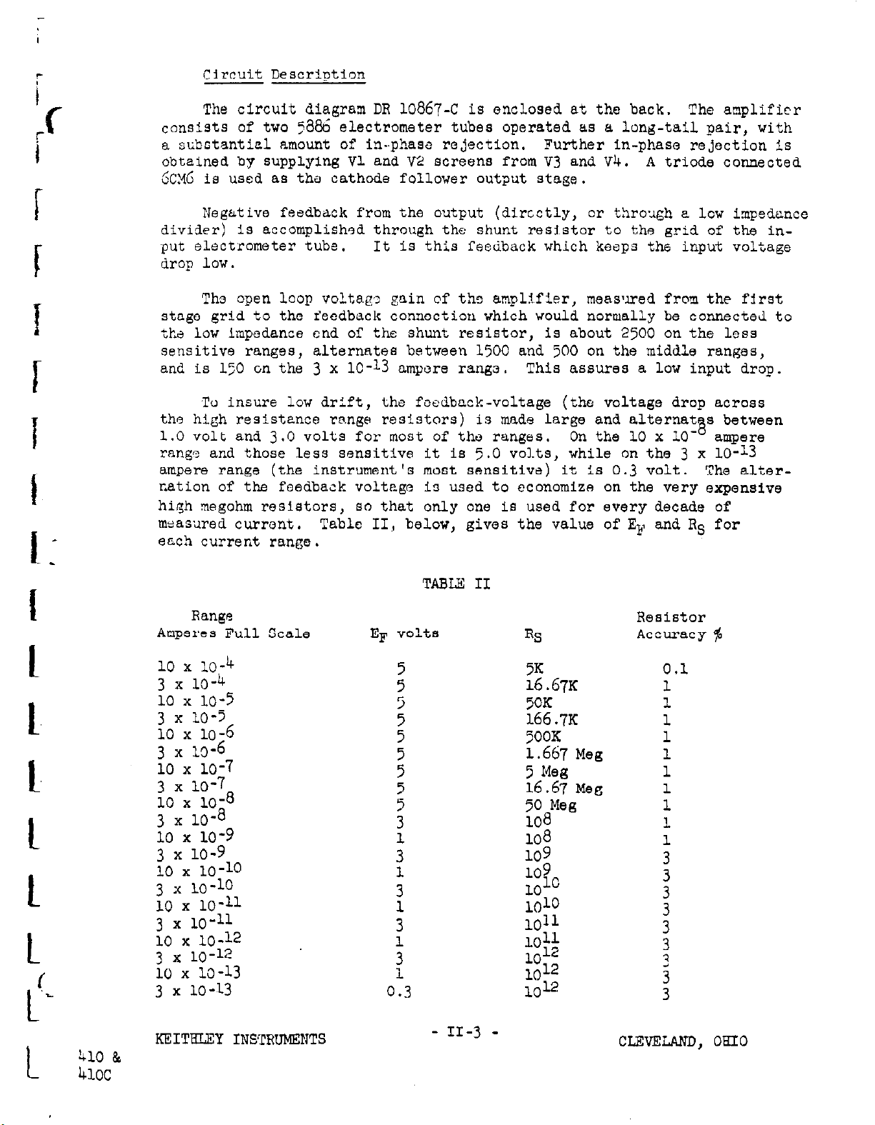
Response Speed of the 410 depends upon the current range being used and
also upon ths capacitance of the external circuitry.
ranges the speed is limited by the amplifier respons
i
I
I
approximately 1,000 cps.
the speed has been reduced to about 1.0 second by the addition of capacitors
across the range resistors.
On thi, ranges from 3 x lo-
On the three most oenoitivo ranges, shunt cap-
acitance across the input limits the response speed.
On the less sensitive
which is from dc to
8,
to 10 x 10-l* ompereo
Because of the method
of application of tim negative feedback, the slowing effects of capacitance
from the high input terminal to ground hs.ve been greatly reduced, but are
still significant.
Tnble I below gives typical response speeds; viz; the
time constant of the response t,o a step functior..
I
I
1
!
I
t
r
‘-
Rang.3 s No significant external capacitance
Undamped
3 x 10-13 2.2 seconds
1 x 10-q 1.0 ”
1 x 10-11
0.15 ”
0.10 ”
: x” ~~-~
1 x 10’ 0.01 ”
-8
0.05 ”
TYPICAL BESPONSE SPEEDS (to read 67% of final value)
Damped
2.2 seconds
1.0 ”
1.0 ”
0.5 0
0.5 I’
0.5 u
I
with 5000 mmf across
I
Undamped
4 seconds
2 I’
.5 :;
.2
.l ‘I
.05 I’
Damped
4
seconds
2 ‘I
1.0 I’
1.0 ”
1.0 ‘I
1.0 ‘I
If the maximum speed of response is desired, the capacitors shunting the
range resistors may be removed; however the increased response to spurious
ac signals may interfore with recording, as mentioned in Section I.
Amplifier Noise is principally power frequency, and is 30 millivolts
ITM max at the OUtpUt t.smhISh, irrespective of the current range. From
the most general point of view, grid current and amplifier zero drift are
also background noise; these have already been discussed,
TABLE I
t
t
c
KEITBLEY INSTRUMENTS
- ‘l-I-2 -
CLEVETELAND, OHIO
Page 6
Circuit Description
The circuit diagram DR 10867-c is enclosed at the back. The amplifier
consists of two 58% electrometer tubes operated as a long-tail pair, with
a substantiel amount of in-phase rejection. Further in-phase rejection is
obtained by supplying Vl and V2 screens from 7.3 and Vk. A triode connected
&X6 is used as the cathode follower output stage.
Negative feedback from the output (directly, or through a low impedance
divider) is accomplished through the shunt resl.star to the grid of the input electrometer tube. It is this feedback which keeps the input voltage
drop low.
Tho open loop volts.g~o gain of ths amplifier, meas’ired from the first
stage grid to the feedback connection which would normally be connected to
is
the low impedance end of the shunt resistor,
sensitive ranges, alternates between 1500 and 500 on the middle ranges,
and is 150 on the 3 x lo-13 ampere range.
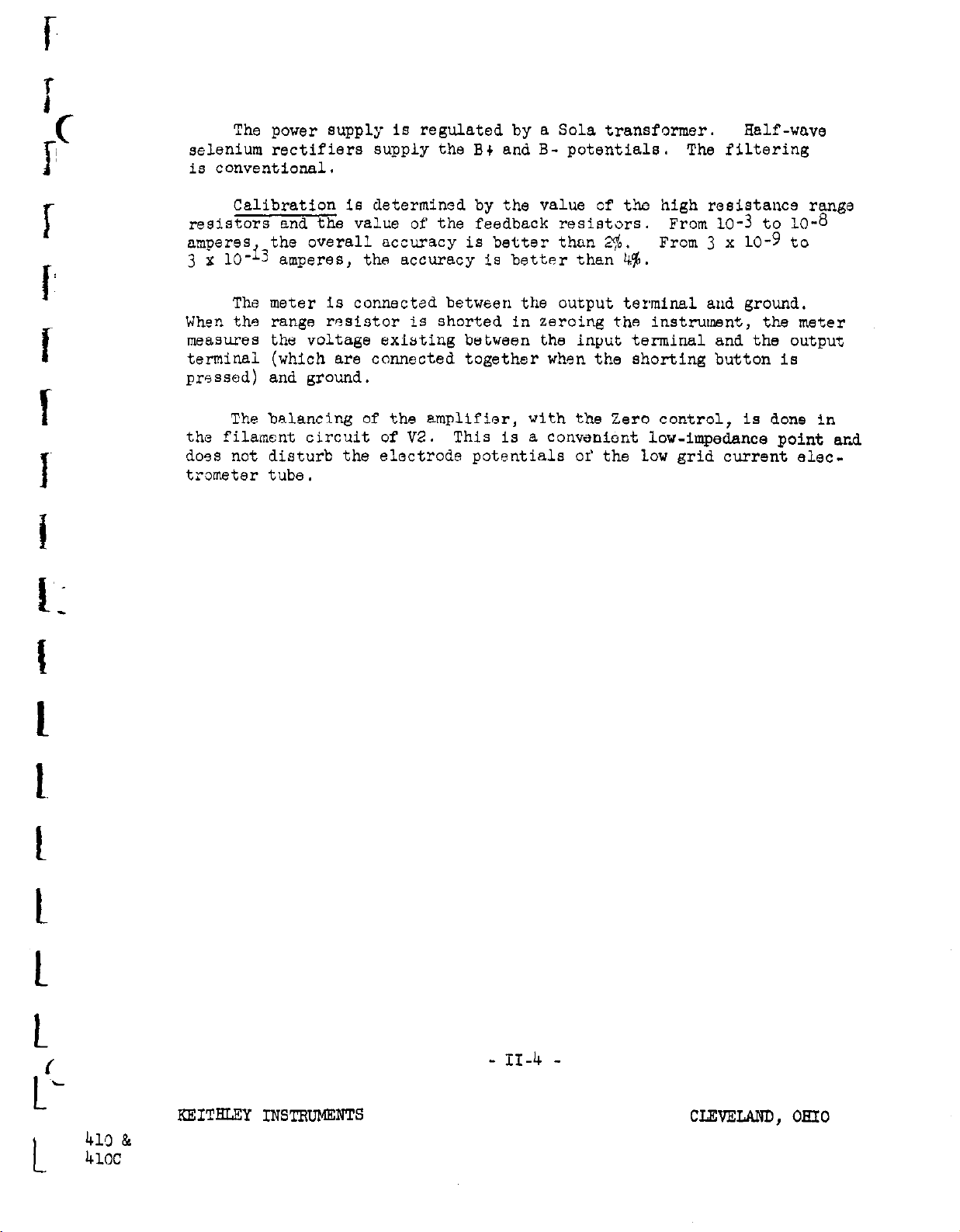
To insure low drift, the feedback-voltage (the voltage drop across
the high resistance range resistors) is made large and alternat
1.0 volt and 3.0 volts for most of the ranges. On the 10 x 10range and those less sensitive it is 5.0 volts, while
ampere range (the instrument’s most sensitive) it is 0.3 volt. The alter-
nation of the feedback voltage is used to economize on the very expensive
high megohm resistors, so that only one Is used for every decade of
m*as;ired current.
each current range.
Table II, below, gives the value of Ep and RS for
This assures a low input drop.
about 2500 on the
on
the 3 x lo-13
1~~s
s between
8
ampere
Range
Ampares Full Scale
10 x 10-4
3 x 10⁻⁴
10 x 10-5
3 x 10⁻⁵
10 x 10-6
3 x 1~6
10 x 10-V
3 x 10⁻⁷
10 x 10-g
3 x 10
10 x 10-g
3 x 10⁻⁹
10 x 10-10
3 x 10⁻¹⁰
;Oxxl,'!;:
10x10-12
~"xx':;~:3
3 x 10-13
-a
:
3
1
0.3
TABLE: II
RS
Z67K
5OK
166.7~
500K
1.667
5 Meg
16.67
::aMeg
108
109
109
1010
1010
1011
1011
1012
1012
1012
Meg
Meg
Resistor
Accuracy $
0.1
1
I.
1
1
1
1
1
1
1
:
:
;
3
;
3
410 &
4lOC
KEIT’LUXY INSTRUMENTS
- 11-3 -
CLEVELAND, OEIO
Page 7
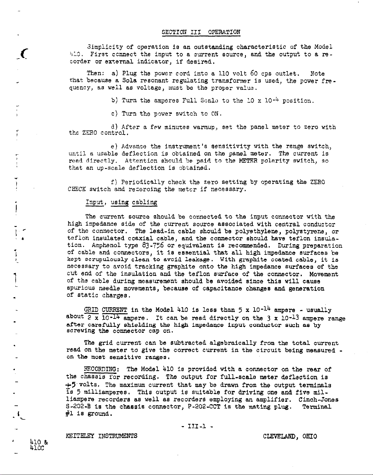
The power supply is regulated by a Sola transformer.
Half -wave
selenium rectifiers supply the B+ and B- potentials. The filtering
is conventional.
Calibration is determined by the value of the high resistance range
resistors and the value of the feedback resistors.
the overall accuracy is better than 2$.
From 10-3 t0 10-a
From 3 x 10-g to
amperes, the accuracy is better than 4%.
The meter is connected between the output terminal and ground.
When the range resistor is shorted In zeroing the instrumnt, the meter
measures the voltage existing between the input terminal and the output
terminal (which are connected together when the shorting button is
pressed) and ground.
The balancing of the amplifier, with the Zero control, is done in
the filament circuit of K?.
This is a convenient low-impedance point and
does not disturb the electrode potentials or’ the low grid current electrometer tube,
L“
t
f
- II-4 -
KEITELEY INSTRuMEmTS CLEVELAND, OHIO
41!l &
4lOC
Page 8
SECTIOll III OPERATION
Simplicity of operation is an outstanding characteristic of the Model
413.
First ccnnect the input to a current source, and the output to a re-
corder or external indicator, if desired.
r
I
T
L
i
-
i, *
i
,
1
Then:
a) Plug the power cord into a 110 volt 60 cps outlet.
Not-2
that because a Sola resonant regulating transformer is used, the power fre-
quency, as weil as voltage, must be the proper value.
b) Turn the amperes Full Scala to the 10 x 10-k position.
c) Turn the power‘ switch to ON.
d) After a few minutes warmup,
set the panel meter to zero with
ths ZERO control.
e) Advance the instrument’s sensitivity with the re.nge switch,
until a usable deflection is obtained on the panel meter.
read directly.
Attention should be paid to the METER polarity switch, so
The current is
that an up-scale deflection is obtained.
f) Pariodically check the zero setting by operating the ZERO
CEXCK switch and receroing the meter if necessary.
Input, using cabling
--
The current source should be connected to the input connector wit,h the
high impedance side of the current source associated with central conductor
of the connector.
.
teflon insulated coaxial cable, and the connector should have teflon insula-
tion.
Amphenol type 83-756 or equivalent is recommended. During preparation
The lead-in cable should be polyethylene, polystyrere, or
of cable and connectors, it is essential that all high impedance surfaces be
kept scrupulously clean to avoid leakage.
With graphite coated cable, it is
necessary to avoid tracking graphite onto the high impedance surfaces of the
cut end of the insulation and the teflon surface of the connector.
Movement
of the cable during measurement should be avoided since this will cause
Spurious needle movements, because of capacitance changes and generation
of static charges.
CBID CUPBFXT in the Model 410 is less than 5 x lo-14 ampere - usually
.
about= X@Gnpere .
after carefully shielding the high impedance input conductor such as by
It can be read directly on the 3 x lo-13 ampere range
screwing the connector cap on.
The grid current can be subtracted algebraically from the total current
read on the meter to give the correct current in the circuit being measured on the most sensitive ranges.
.
PBCOPDING:
the chassis for recording.
The Model 410 is provided with a connector on the rear of
The output for full-scale meter deflection is
+5’volts. The maximum current that may be drawn from the output terminals
is 5 milliamperes.
This output is suitable for driving one and five mil-
liampere recorders as well as recorders employing an amplifier. Cinch-Jonas
S-202-B is the chassis connector, P-202~CCT is the mating plug.
Terminal
#l is ground.
- III-1 -
KEITHL?lX INSTBDMgNTS
cmLAND, OHIO
Page 9
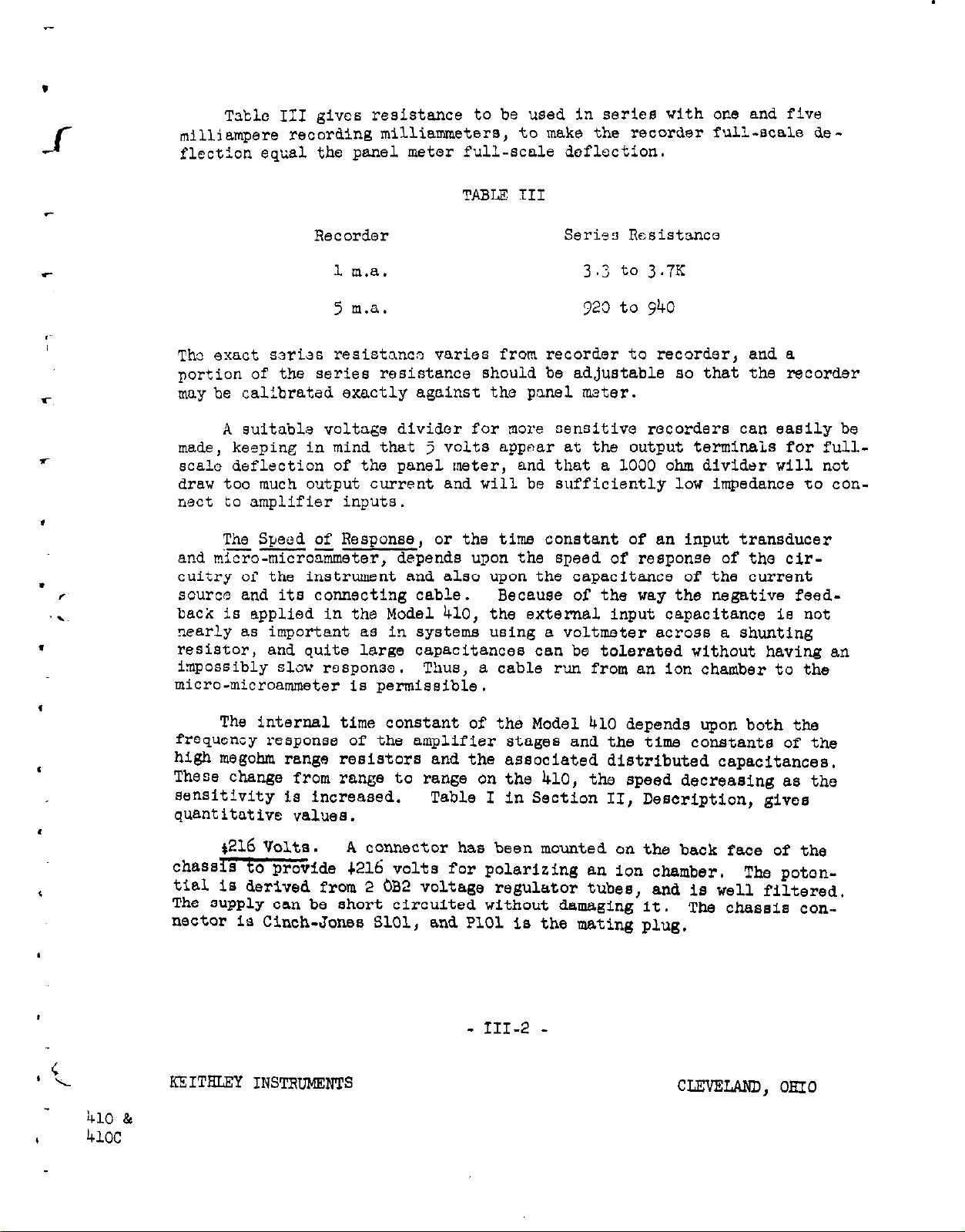
Tsblc III gives resistance to be used in series with one and five
milliampere recording milliammatera,
to make the recorder full-scale de-
flection equal the panel meter full-scale deflection.
TABLE TII
Recorder
1 m.a.
5 m.a.
The exact aeriss reaiatanco
varies from recorder to recorder, and a
Serisa Resistance
3.3 to 3.7K
323 to 940
portion of the series resistance should be adjustable ao that the recorder
may be calibrated exactly against the panel mater.
A suitable voltage divider for more
sensitive recorders can easily be
made, keeping in mind that 5 volts appear at the output terminal.3 for full-
,
scale deflection of the panel meter,
and that a 1000 ohm divider will not
draw too much output current and will be sufficiently low impedance to connect to amplifier inputs.
I
The Speed of Reaponae, or the time constant of an input transducer
and mico-nio%%ueter, depend8 upon the speed of response of the cir-
s
,
.~
cuitry of the instrument find also upon the capacitance of the current
source and its connecting cable.
Because of the wag the negative feedback ia applied in the Model 410, the external Input capacitance is not
nearly a.8 important aa in systems using a voltmeter acroaa a shunting
.
resistor, and quite large capacitances can be tolerated without having an
impossibly slow response.
Thus, a cable run from an ion chamber to the
micro-microammeter is permissible.
The internal time constant of the Model 410 depends upon both the
frequency response of the amplifier stages and the time constanta of the
high megohin range reaiatora and the associated distributed capacitancea,
These change from range to range on the 410, the speed decreasing aa the
sensitivity is increased.
Table I in Section II, Description, gives
quantitative values.
t216 Volta.
chaaa& to provide 4216 volts for polarizing an ion chamber,
A connector has been mounted on the back face of the
The poton-
tial ia derived from 2 bB2 voltage regulator tubea, and is well filtered,
The supply can be short circuited without damaging it, The chaaaia con-
nector ia Cinch-Jones SlOl, and PlOl is the mating plug.
- III-2 -
K!CITELEf INSTRTJMgNTS
CLEVELAND, OHIO
Page 10
SECTICN IV MAINTENANCE
-
The Keithley
Lang, trouble-free service.
throughout,
and the circuits are stabilized by a substantial amount of
Model
4.10 Micro-microammeter has been designed to give
ILigh quality components have been used
negative feedback.
DR
10867-c,
of the Plodal 410.
at the back, is the detailed circuit schematic diagram
The circuit operation was discussed in Section II,
Description.
Maintenance Adjustments
One maintenance control is provided. It is accessible from the to!,
of the chassis,
3138,
,ME?%R CALq3RATION, is in series with the Mater. To recalibrate,
and is located behind the meter.
use the 13 x 10-j ranSe and, with 7 x 10-b ampere through the input circuit, adjust
~138
so the meter reads exactly
7.0.
Since the shunt resistor
cn this range is accurate to 0.1s of its nominal value the overall accuracy
can be adjusted to about 1% of full scale. Cn the
3
4 to 10 x 10-9 amper*
X ID
rengc tha range resistors are act‘ T ate to 1% and, providing the calibration
was accurately done on the LO x lr range, the overall accuracy will be 2$,
From 3
x 10-g to 3 x lo-13 anpares the range resistors are accurate to
34
and the overall accuracy will be 476.
,/
i.
Vacuum Tubes Vl and V2 are the two electrometer tubes, and are located in
an aluminum can which plugs onto the top of tha chassis near the input
terminals.
Keithley part EV5886-5 and V2 is
is that
tiiat the complete Input Tube assembly Model
The tubes have been selected, matched and labelled; Vl is
EV>886-6
~~5066-6.
does not have to hnve low grid current.
The difference between the two
It is recommended
4102,
be kept for replacement
purposes.
t
I
I
/
k-
i10 &
4mc
The other tubes are standard receiving tubes and need no special selec-
tion to assure satisfactory performance of the Model 410.
INSULATION: All insulation for the high impedance conductors Is made
of teflon, as are the contact insulators on the range switch. This should
give satisfactory service in all humidities. Occasionally, the high im-
pedance insulators should be inspected to insure that they are free from
dirt and dust.
CONNECTOR CAP: The cap for the input connector should be kept in
place whenever the connector Is not being used. In storage and in tranaport, it keeps the insulation from accumulating dust and dirt.
Before
screwing the cap back onto the connector, be certain that it is clean, so
the insulation will not be contaminated.
- Iv-1 -
KEITHLEY IKSTRIJMENTS
CLEVELAND, OHIO
Page 11
SECTION V SPECIAI INSTBUCTIONS FOR THE MODEL 410C
DB 11165-c is the circuit schematic diagram of the Model 410~.
It differs from the 410 in providing the meter contacts, and
the relay which is controlled by them.
The meter-relay is manufactured by Assembly Products, Inc.,
of Chesterland, Ohio, Model 461-c. Its contacts will close
vhen the black meter pointer coincides with the red index
pointer.
The index can be set easily to any point on the
meter scale by rotating the black knob on the front of the
meter.
To obtain reliable contacting of the meter, the contacts are
locked together electrically.
Unlocking can be accomplished
by operating the FZSZT button on the panel, or by a remote
switch.
To complete the locking path, it is necessary that contacts A
and B of the AN connector be connected. This can be done
within the mating male plug, if resetting is to be done only
with the panel button,
or leads can be run to a remote reset
relay or switch.
The one AN connector, it will be seen on the schematic diagram,
is used for the resetting circuit, control relay contacts, and
the output to a recorder.
.
The relay contacts are rated 5 amperes at I.10 volts AC, or
24 volts DC.
- V-l -
KEITBLEY INSTRUMENTS
CLErnLAND, OHIO
Page 12
This report is intended to SUP ,ly data on performance in addition to
or outside of our published specifications.
Measurements are made on
stock instruments and are to serve as a guide rather than a limitation
or guarantee of Performance of any particular instrument.
Pour Pests are inciuded:
1) @verload characteristics
2) Linearity
31 Response Speed
4) Drift
MODFL 410
Pigute 1 shows the performonce of the output signal with several full
scales overload.
Curves are shown for no load
and
for llC load.
and the input signals used were both positive and negative.
t
/
Figure 2 shows the linearity between negntive full scale and positive full
scale, 11s may be seen, it is so good it is hard to r*eaSureo This is
the anplifier output only and has nothing to do with meter linearity.
i
Please note that the range used employs one volt feedback, The
linearity may be expected to be 3 times a8 good on ranges using 3 ~.~lte.,
5 times as good on ranges using 5 Mlta and onlyd times as good on the
most sensitive range.
Chart 3 is a listing of response speeds for all decade ranges and ths most
sensitive ‘range with small input capacity and with 5000 mmf input
capacity,
for
the standard unit and for the standard unit with range
switch capacitors remvad.
On some
ranges,
overshoot is encountered.
Por these, the overshoot in
percent of full scale is recorded.
The times given are to reach 90% of final value. Conversion to standard
eLectriCa *‘the constant” is made by dividing by 2.3. For example,
the Standard unit on the 10 x 10-12 range has a 90% reSPoMe time of
2.3 secoxxls.
This means a “time constant” of 1 second.
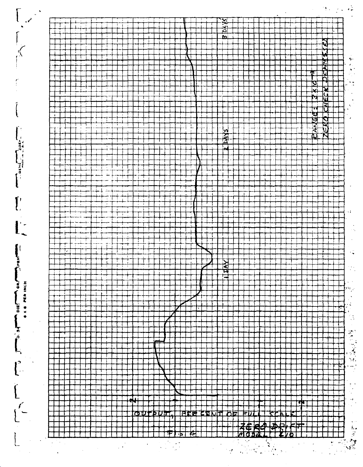
Figure 4 shows the 3uday drift record of a “typicsl” unit. Remember that,
e
on
-.
any iang~s, the drift record will be ftbes *s good as the record
.3
,
shown <on the 3 x IO-13 range, the feedback voltage is .3 volts). Thus,
on any range a’mve 10 x 10-g (ef
= 5~) the scale of Fig. 4 could be
compressed Lb .‘I times .
Page 13
,’
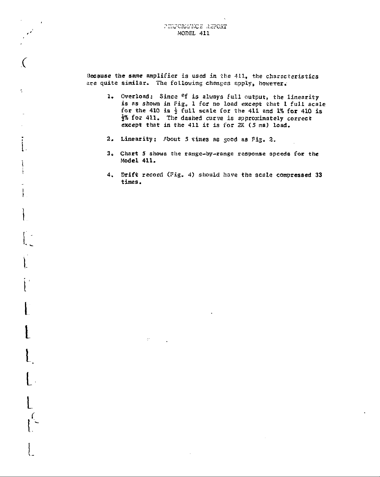
kceuse the same amplifier is used in the 411, tJle characteristics
are quite similar. The falLowing changes apply, however.'
1. Overload :
is AS shown in Fig, 1 for no load except .that 1 full scale
for the 410 is $ full scale for the 411 and 1% for 410 is
1% for 412.
except that
2. Linearity:
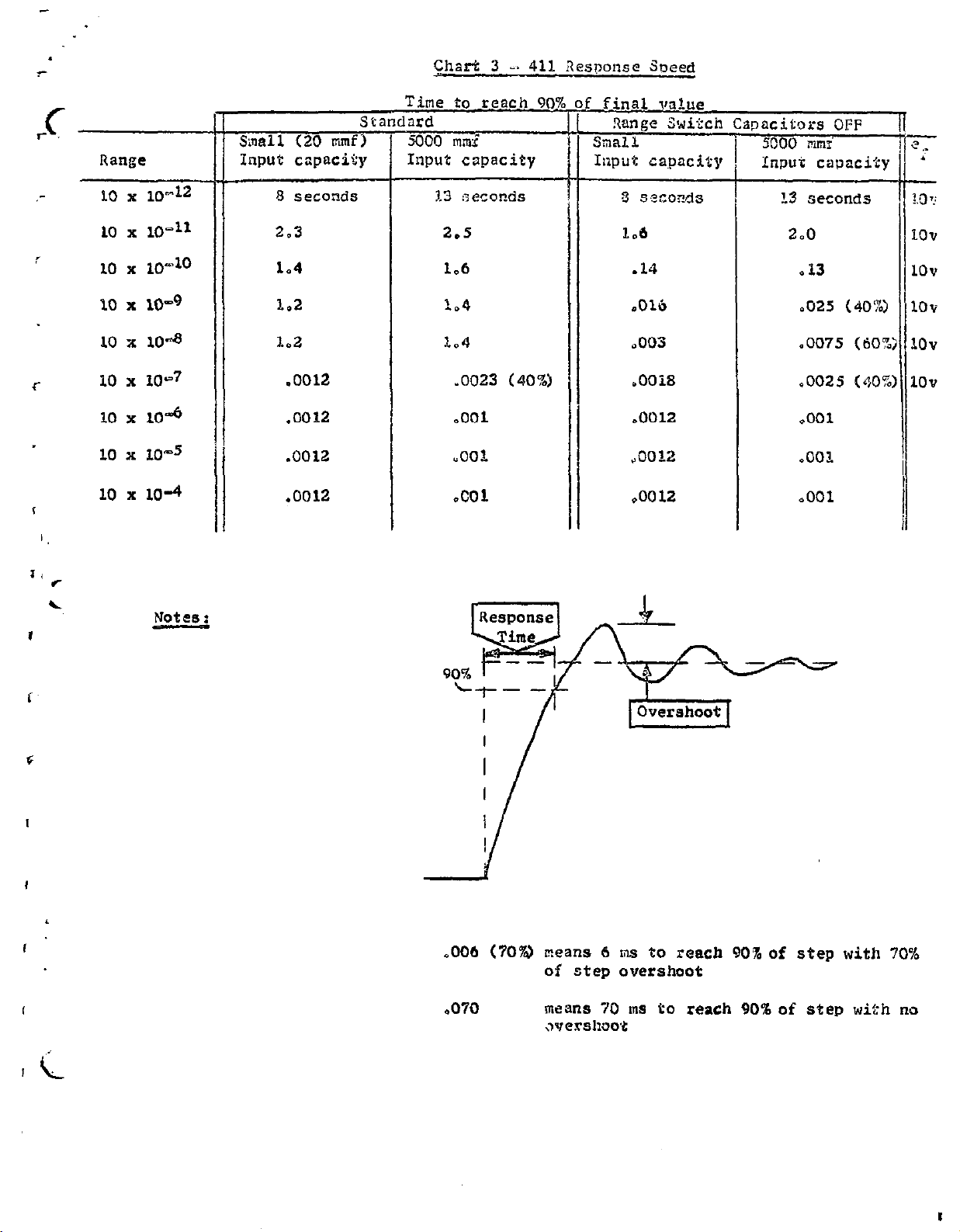
3. Chart 5 shows the range-by-range response speeds for the
Model 411.
4. Drift record (Fig. 4) should have the Scale compressed 33
times.
Since ef is always full output, the iineerity
The dashed curve is approximately correct
in
the 411 it is for 2K (5 ma) load.
fibout 5 times ~6 gcod a8 Fig. 2.
Page 14

Page 15
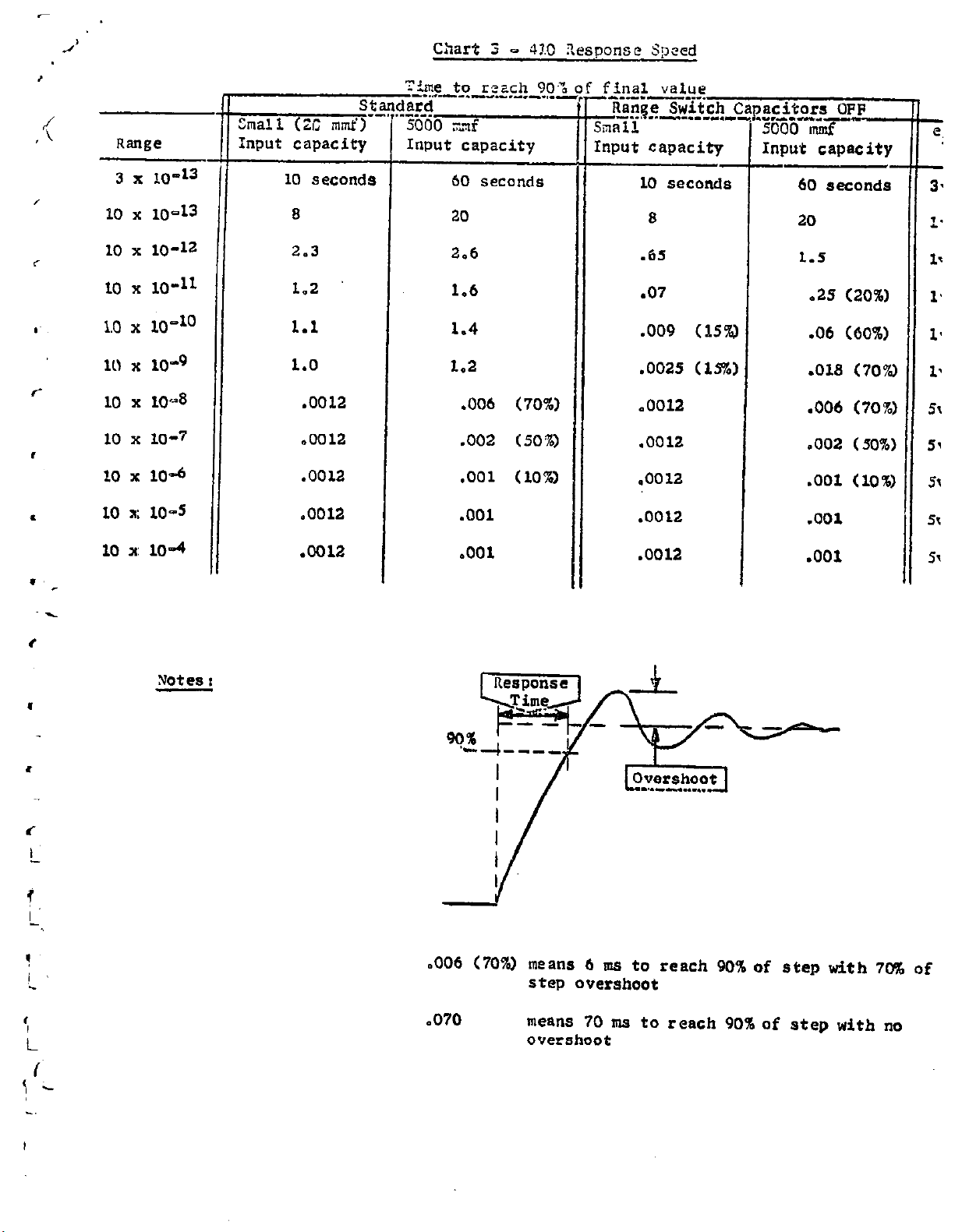
Chart 3
- 4!.0 Zesponsc Speed
Range
3 x 10-13
10 x 10-13
10 x
10-12
to x 10-11
1.0 x 10⁻¹⁰
10 x 10-9
10 x
10 x 10-7
10 x 10-6
10 a: 10-s
104
Sl
hall (21; rn~d)~
Input capacity
10 seconds
8
2.3
1.2
1.1
1.0
.0012
.0012
.0012
.0012
‘?‘ime to r-ach 90%
--..“-..-.A- .-_-.,._
iard
.-.-.
5000 x7f
Input capacity
60 seconds
20
2.6
1.6
1.4
1.2
.006 (70%)
.002 (50%)
,001 (10%
,001
final value
------‘7‘
Ranqe Switch Capacitors OFF
g--yi. I.--.--...- ~..“.o.~-,.,:nput capacity
10 seconds
8
.65
.07
.009 (ISYPJ
,002s (1%)
.0012
.0012
.oo 12
.0012
Input capacity
I
60
8eCOnd8
20
1.5
.29 (20%)
.06 (60%)
.018 (70%
.006 (70%:
.002 (50%1
.OOl (10%)
.OOl
10 x: 10-4
Notes :
.0012
.OOl
.0012
.OOl
II
.006 (70%) mean8 6 m8 to reach 90% of 8t@p with 70%
step overshoot
of
.070
mean8 70 ms to reach 90% of step with no
overshoot
Page 16
f
.
Chart 3 -. 411 Response Speed
10 x 10-4
II
11 Small (20 rmf)
Input capacity
-0012
Tine to teach 90:
sta
lard
5COO mms’
Input capacity
%3
otconds
2.5
1.6
1.4
1.4
-0023 (40%)
,001
“001
.COl
final value
Range
ball
Input capacity
Switch
8 3ecoxls
I.6
-14
.Olb
.003
.OOiS
-0012
“0012
-0012
pncitors OFF
5000 mm:
Input capacity
?3
Seconds
2.0
-13
,025 (40%)
-007.5 (60%:
-002.5 (40%:
,001
,003.
,001
Notee:
,006 (70%)
,070
means
6 ms to reach 909of step with 70%
of step overshoot
mean8
70
m8
to reach 90%of
,vfershoo4
step
with no
Page 17
Page 18

SCEITHLF;Y MODEL
410.
TROUBLE
SHOOTING
PROCED~ .
FAULT:
PROCEDURE:
Will not zero.
ues QTVM, PO voltages
Cheok power
A.
Inaut oan
Su@ply end at R $%%I $5"3,"1'n 7; -
2
V5 pin 9; + 150
3.
If voltagse
oomponente.
The rollowlng potentials will depend on the eettlng
B.
of the ZERO oontrol.
awing the oheok
adJuetlng the
&age la working.
where the voltage
oheok the tube and then the oomponents or that stage.
Refer to Sohematlo DR 10867-O
referred
eup
ly voltage6
(4102
P
are
lnoorreot, oheok power supply tubes and
to gzwurxl.
14ov
However, if It is poeeible to
olnt through the oorreot value by
zl&
0 oontrol it may be amumed that the
Prooeed
value
until the point 16
oannot be obtained. Then
iound
8.
Imut oan Din
2
11:
In&t
Input
Input oan pln 9
12.
ZERO oontrol.
13. v3
14. QJ
15. vg
.
? Q
ii:
20.
Q
z
V5
6
oan oan pii
and
wiper,
pin
7
8
10
atiPI: ?O%)
and Q4 pln 2
aM7 i
and V4
pin 6 ;
_ _
mn 5
pin 5 i
(64~6 pin
pin ; 3 & 6
pin
1
7
i -I- 8v
$- ;y
. v
0
+ lV
-t 10'
;
-p 11.5v
-c 47v
i
z 7;sov
+ 1300
;
-1ov
0
I
Page 19
% 1
/ 1
c
,
,-_L . -~
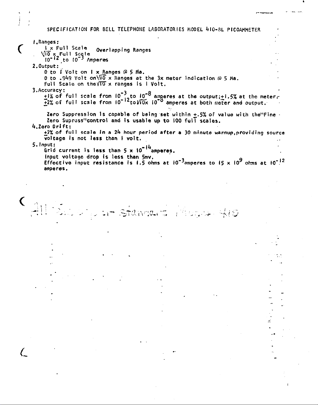
SPECIFICATION FOR BELL TELEPHONE LABORATORIES kOOEL 410-BL PlCOAHnETER
l.Ranges:
I x Full Scale
VIE x Ful I SC le.
IO”2 to
-4
IO hpe Pe5
Overlapping Ranges
2.output: :.
0 to I Volt on I x Ranges 0 5 Ma.
0 to .94g Volt on\cx Ranges at the 3x meter indication (a 5
Ha.
Fuli Scale on theVfUx ranges is I Volt.
3,Accuracy:
am eres
5
lo-
at the output;+l.s% at the meter.-
amperes at both meer and output:
-.
Zero Suppression is capable of belng.set within 2.5% OF value with the”Fine Zero Suprass’kontrol and Is usable up to 100 full scales.
4.2ero
Drift:
22% of full scale In a 24 hour period after a 30 minute warmup,providIng source
voltage is not less than I volt. . .
5. Input:
Grind current is less than 5 x
IO
-14
amperes.
Input voltagc drop is less than Smv.
Effective input reslstance is
I.5 ohms
at 10-3emperes to IS x IO9 ohms at IO-J2
8mperes.
.
.
.
Page 20

REPLIICE?BLE PARTS LISP - MODEL 410
_.-..-._ .._-
circuit
De&g.
.---.- .__,
Cl01
Cl02
Cl02
Cl04
Cl05
Cl06
Cl07
c401
c402
c403
_--.. ._
--.- _-.... .._- ..__. -.
_ -.----.-~__.-.-_
Description
-_._-.-
Capacitor, polystyrene, 5000 mmf, 100
-----..---._-
WV,
25%
Capacitor, polystyrene, 500 mmf, 100 WV, 25%
Capacitor, polystyrene, 50 mmf, 100 WV, 25%
Capacitor, polystyrene, 5 mmf, 100
WV,
25%
Capacitor, ceramic, 0.02 nfd, 600 WV, GMV
Capacitor, ceramic, 100 mmf, 600 WV, 10%
Capacitor, ceramic, .OOl mfd, 600 WV. 10%
Capacitor, electrolytic, 40 mfd, 250 WV
Capacitor, electrolytic, 150 mfd, 150 WV
Same as C401
__-_- ..__.. -.
.._.
Part
No.
CSl-5000
C7’1”SOO
C31”50
c31-5
c22-:02
c22-100
C):.Z-.Ml
C27-40
c9 -150
c404
c405
C4O6
c407
C408
PU 1
ME1
RlOl
R102
It103
R104
RlO5
Same as
Sane as
C402
C401
Capacitor, electrolytic, 20 mfd, 450 WV
Capacitor, ceramic, 0.02 mfd, 600 WV
Capacitor, oil filled, 1.0 mfd,
Puse, 1.5 amp type
3AG
85OV
AC
Meter, O-200 micro-amperes, illuminated dial.
Meter
bulbs G.B. type 323. ?L - \
---
Resistor, wire wound, 5K, 0.1%. jvU
Resistor; deposited carbon, 16.67K, 1% 1W
Resistor, deposited
carbon, 50k,
1%. 1W
Resistor, deposited carbon, 166.7K, 1% 1W
Resistor, deposited carbon, JOOK, 1%. l?J
C8 ZOL
c22-32
FU -G
MB -6
RlO-16sSK
R13-16.67K
R13 -5OK
Rl?-166.7K
R13-500K
R106
R107
R108
R109
Resistor, deposited carbon, 1.667
Resistor, deposited carbon, S
meg,
neg.
1%. 1W
l%, W
Resistor, deposited carbon, 16.67 meg, 1%. 1W
Resistor, deposited carbon, 5Q meg, 1% 2W
R13-t.667M
R13-!iM
R13-16.57M
Rl4-50M
Page 21

REPIACW\DLE PARTS LIST - MODEL 410
cirCTii
Desig.
RllO
Rlll
R112
R113
Rll4
RI15
Rll6
Rl17
R.118
R119
R120
Description
Resistor, deposited carbon, 100 meg, l%, 2W
Resistor, high megohm, 10' ohms, 3%
Resistor, high megohm, 101oohms, 3%
Resistor, high megohm, 101lohms, 3%
Resisotr, high megohm, 101'ohms, 3%
Resistor, wire wound, 2K, 0,257.. ?H
Same as Rl1.S
Resistor, wire wound, 700 ohms, 0.25%
Resistor, wire wound, 300 ohms, 0.25%,
:W
iw
Resistor, composition carbon, 22 meg, 10%.
Resistor, deposited carbon, 10
meg,
1%. llV
:lV
Part
_.._ ~.._-.. ..-
No.
R14..1.!)OM
R20k7
R20-10”
R20-10”
R20-IO"-
R18"15-2k
R18-lS-:Oo
1~18-15-300
Rl-22M
R13..10M
R121
R122
Rl23
Rl24
R125
R126
R127
II128
R129
R130
R131
R132
R133
Same ns R120
Potentiomctar, ten turn, 200
Resistor,
power
12.5K. 7W, 3%
ohms,
5% tol.
Same as Rl23
I'
Resistor,
/
Resistor, wire wound, 150 ohms,
Resistur,
deposited carbon, lOOK, 1/3W, 1%
{W,
1%
wire
wound, 250 ohms,
$V,
1%
Resistor, deposited carbon, 2OK. l/3&', 1%
Resistor, composition carbon,
lOK,
$W,
Resistor, deposited carbon, 1 meg, 1/3W, 1%
Resistor, deposited carbon, 60K, 1/3!q, 1X
Sami? as R130
Resistor, deposited carbon, 5
mcg,
lW, 1%
10%
RP4-200
R7-12.M
R12..10OK
RlS-6-150
R186-2.50
Rl2-2OK
Rl:-1OK
R12-IM
RlZ-hOK
R13-5M
R134
R135
R13b
Resistor, deposited carbon, 8 meg, lW, 12
Sme as R123
Resistor, wire wo-: :, 22.5K, $d,
1%
R13-8t.i
RlS-lo-22.5K
Page 22

Circuit
Desig.
_.. .,_.
R137
REPLACRABLE PARTS LIST - MCDRL 410
Description
_ _._.., ~~._. _ .,_. ~..
,,.... __,_._,..._ -,__-..--.I- .-...., --- ----_--
Potentiometer, wire wound, SK, 2W, 20%
-_-__.---Part
NO.
RP34E
R401 Resistor,
R402
Resistor, composition carbon, 470 ohms, IW, 10%
composition carbon, 100 ohms, {W, 10%
R403 Same as R401
R404 Same as R402
R40.5 same as R401
I7406 Same as R401
R407 Resistor, power, lOK, SW, 3%
R408 /Resistor, composition carbon, lOOK,
SRI
Rectifier,
j
selenium, 65 ma., 130 V AC input
SR2.3,4,5,6 Same as SRl
t
SW1
SW2
SW3
'Range Lwitch,
I
Input shorting switch, teflon insulated
Meter Polarity,
teflon insulated
switch, DPDI toggle
+W,
10%
Rl-103
U-470
R4-LOK
Rl-100K
RP-1’1
SW-30
SW-14
SW4
TX
Vl
v2
v3
v4
V5
V6
v7
Power line switch, DPDT toggle
ransformer regulating; Pri, 100~130~. 60 cps;
Sec. 1, 600~ de. 0 20 ma,
1
center
tapped;
Sec. 2. 250~ dc. B 50 ma, center tappedf
Set 3, 6.3~ ac. G 0.6A;
Sec. 4, 6.3~ ac. f3 OhA;
Sec. 5, 6.3, ac. 8 2.@A
Furnished with C408, tuning capacitor
Blcctrometcr lube, Raytheon CK 5gg6, matched
it11 v2
I
Electrometer tube, Raytheon CR 5886, matched
with Vl
I
Vacuum tube, type 6CB6
I
i
ssmc as v3
$acuum tube, type 6CM6
vacuum tube, type 082
I
+m! as Vb
I
Same as SW3
TR-17
EV 5086-5
BV 5886-6
w 6cB6
BV bCM6
IN 002
Page 23
:
I
I
i-
I
Circuit-
Desig.
-_---_.
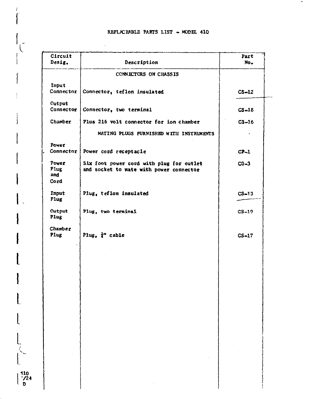
Input
Connector
output
Connector
RBPLXPABLB PARTS LIST - MODEL 410
--
Zonnector, teflon insulated
Zonnector, two terminal
Description
--_
cohul3xcws ON CHASSIS
Part
No.
cs-12
c&l8
--
--
I.
I
I
t
Chamber
Power
Connector
Power
Plug
and
Cord
Input
Plug
output
Plug
Chamber
Plug
?lus 216 volt connector for ion chamber
MATING PLUGS PURNISHED WIT11 INSTRUMmS
?ower cord receptacle
iix foot power cord with plug
md
socket
‘lug, teflon insulated
‘lug, two terminal
‘lug, $’ cable
to aate with power connector
for
outlet
cs-16
CPA
co-3
q-13
--cs-1.9
cs-17
t
L
410
'/24
I
D
Page 24

-
-- -
-, .
F?-7
--P---..T--.~
, 1
- - --~ ~, _
rl
-
Page 25

I
c
FRodt- V/Ew
I I
I /
/
Page 26

-.
i
Page 27

i
I
I
I
I
‘UT
Top:
Page 28

r
r----
1
.r-----------1
I
I
I
f)
OUTPUT
CONNLCTC+?,
II I
I
 Loading...