

Page 1
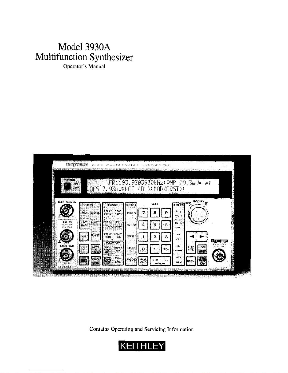
Model 3930A
Multifunction Synthesizer
Operator’s Manual
Contains Operating and Servicing Information
Page 2

WARRANTY
Keithley Instruments, Inc. warrants this product to be free from defects in material and workmanship for a period of 1 year from date of
shipment.
Keithley Instruments, Inc. warrants the following items for 90 days from the date of shipment: probes, cables, rechargeable batteries,
diskettes. and documentation.
During the warranty period, we will, at our option, either repair or replace any product that proves to be defective.
To exercise this warranty, write or call your local Keithley representative, or contact Keithley headquarters in Cleveland, Ohio. You will
he given prompt assistance and return instructions. Send the product, transportation prepaid, to the indicated service facility. Repairs
will be made and the product returned, transportation prepaid. Repaired or replaced products are warranted for the balance of the original warranty period, or at least 90 days.
LIMITATION OF WARRANTY
This warranty does not apply to defects resulting from product modification without Keithley’s express written consent, or misuse of
any product or pti. This warranty also does not apply lo fuses, software, non-rechargeable batteries, damage from battery leakage, or
problems arising from normal wear OI failure to follow instructions,
THIS WARRANTY IS IN LIEU OF ALL OTHER WARRANTIES, EXPRESSED OR IMPLIED, INCLUDING ANY IMPLIED
WARRANTY OF MERCHANTABILITY OR FITNESS FOR A PARTICULAR USE. THE REMEDIES PROVIDED HEREIN ARE
BUYER’S SOLE AND EXCLUSIVE REMEDIES.
NEITHER KEITHLEY INSTRUMENTS, INC. NOR ANY OF ITS EMPLOYEES SHALL BE LIABLE FOR ANY DIRECT, INDIRECT, SPECIAL, INCIDENTAL OR CONSEQUENTIAL DAMAGES ARISING OUT OF THE USE OF ITS INSTRUMENTS AND
SOFTWARE EVEN IF KEITHLEY INSTRUMENTS, INC., HAS BEEN ADVISED IN ADVANCE OF THE POSSIBILITY OF
SUCH DAMAGES. SUCH EXCLUDED DAMAGES SHALL INCLUDE, BUT ARE NOT LIMITED TO: COSTS OF REMOVAL
AND INSTALLATION, LOSSES SUSTAINED AS THE RESULT OF INJURY TO ANY PERSON, OR DAMAGE TO PROPERTY.
Page 3

Model 3930A Multifunction Synthesizer
Operator’s Manual
0 1991, Kcithlcy Instruments, Inc.
Test Instrumentation Group
All rights reserved.
Cleveland, Ohio, U.S.A.
August 1991, First Printing
Document Number: 3930A-900-01 Rev. A
Page 4

All Keithley product names are trademarks or registered trademarks of Keithley Instruments, Inc.
Other brand and product names are trademarks or registered trademarks of their respective holders.
Page 5

Safetv Precautions
The following safety precautions should be observed before using the Model 3930A Multifunction Synthesizer and any
associated instruments.
This instrument is intended for use by qualified personnel who recognize shock hazards and are familiar with the safety
precautions required to avoid possible injury. Read over this manual carefully before using the instrument.
Exercise extreme caution when a shock hazard is present at the te.st circuit. The American National Standards Institute
(ANSI) states that a shock hazard exists when voltage levels greater than 30V nns or 4.2.4V peak are present. A good
safety practice is to expect that hazardous voltage is present in any unknown circuit before measuring.
Inspect the connecting cables and test leads for possible wear, cracks, or breaks before each use.
For maximum safety, do not touch the test cables or any instruments while power is applied to the circuit under test.
Turn off the power and discharge any capacitors before connecting or disconnecting cables from the instrument.
Do not touch any object which could provide a current path to the commc~n side of the circuit under test or power line
(earth) ground. Always make measurements with dry hands while standing on a dry, insulated surface capable of withstanding the voltage being measured.
Instrumentation and accessories should not be connected to humans.
Page 6

Page 7
Table of Contents
SECTION 1 - General Information
1.1
1.2
1.3
1.4
1.5
1.6
1.6.1
1.6.2
1.6.3
1.6.4
1.7
1.8
INTRODUCTION .....................
FEATURES
..........................
WARRANTY INFORMATION ...........
MANUAL ADDENDA
SAFETY TERMS AND SYMBOLS .........
UNPACKING AND REPACKING
........
Unpacking
........................
shipment contents ..................
Operator’s Manual ..................
Repacking For Shipment ..............
OPTIONAL ACCESSORIES .............
SPECIFICATIONS ....................
SECTION 2 - Getting Started
2.1
2.2
2.2.1
2.2.2
2.3
2.3.1
2.3.2
2.3.3
2.4
2.5
2.5.1
2.5.2
2.5.3
INTRODUCTION
..................
INSTALLATION
..................
Installation Location ..............
Fan ...........................
LINE POWER SUPPLY ..............
LINE Voltage Selector Switch .......
Line Receptacle Connection .........
Line Fuse ......................
HANDLING PRECAUTIONS .........
BASIC OPERATION ................
Front Panel Summary .............
Typical Test Connections ..........
Operating Examples ..............
...........................
...........................
...........................
...........................
...........................
...........................
...........................
..........................
..........................
..........................
..........................
..........................
..........................
..........................
..........................
..........................
..........................
..........................
..........................
..........................
..........................
..........................
..........................
1-l
1-l
l-2
l-2
l-2
l-2
1-2
1-2
l-2
l-3
l-3
l-3
2-l
2-l
2-1
2-l
2-2
2-2
2-2
2-2
2-3
2-3
2-3
2-3
2-5
SECTION 3 - Operation
3.1
INTRODUCTION ..............................................................
3-l
3.2
FRONT PANEL AND REAR PANEL DESCRIPTION
...................................
3-l
3.2.1
Front Panel Description.
....................................................... 3-l
3.2.2
RearPanelDescription ........................................................
3-12
3.3
Input and Output Connections
.................................................... 3-13
3.3.1
InputConnections ...........................................................
3-13
3.3.2
outputConnections.. ........................................................
3-14
3.4
STARTUP
....................................................................
3-15
3.5
OPERATINGPROCEDURES
..................................................... 3-16
3.5.1
Setting Parameters Using Numeric Keys
...........................................
3-16
Page 8
3.5.2
Setting Parameters using MODIFY .............................
3.5.3
ErrorCodes
..............................................
3.5.4
UnitsConversion ..........................................
3.5.5
Frequency Programming .....................................
3.5.6
Output Amplitude and Amplitude Modulation
....................
3.5.7
DC Offset Programming .....................................
3.5.8
Waveform Selection, Square-Wave Duty Cycle, and Synchronous Output
3.5.9
OscillationMode ...........................................
3.5.10
Trigger Parameters (Source, Rate, Burst Cycle, and Phase)
............
3.5.11
Frequency Sweep Operation ..................................
3.5.12
OutputRangeMode ........................................
SECTION 4 -
GPIB Interface
4.1
4.1.1
4.1.2
4.1.3
4.1.4
4.1.5
4.1.6
4.1.7
4.1.8
4.1.9
4.2
4.2.1
4.2.2
4.3
4.3.1
4.3.2
4.4
4.4.1
4.4.2
4.5
4.6
4.7
INTRODUCTION ..............................
GPIB Overview ..............................
Major GPIB Specifications ......................
Bus Line Signals and Operation ..................
GPIB Handshaking ...........................
Data Transfer Example ........................
Basic Talker Functions .........................
Basic Listener Functions .......................
Basic Controller Functions ......................
Multi-Line Interface Messages ...................
OVERVIEW OF MODEL 3930A GPIB INTERFACE
.....
Introduction ................................
Specifications __._ ._ __ ._ ._ _______ _._ __
MODEL 3930A PROGRAM CODES ................
Model 3930A Parameter-Setting Messages
..........
Model 3930A Inquiry Messages ..................
MODEL 3933A PHASE SHIFIIZR PROGRAM CODES.
..
Model 3933A Phase Shifter Parameter Setting Messages
Model 3933A Phase Shifter Inquiry Messages
.......
TYPICAL EXECUTION TIMES ....................
PROGRAM CODE SUMMARY TABLES
.............
SAMPLEPROGRAMS ..........................
4-l
4-l
4-l
4-2
4-2
43
4-3
4-3
4-4
44
4-6
4-6
4-6
4-10
4-10
4-21
4-26
4-26
4-32
4-35
4-38
4-43
Page 9
List of Illustrations
SECTION 2 - Getting Started
Figure 2-l Front Panel Summary
Figure 2-2
TypicalConnections ..___.___...._._..._.._...___.........
SECTION 3 - Operation
Figure 3-1
Figure 3-2
Figure 3-3
Figure 34
Figure 3-5
Figure 3-6
Figure 3-7
Figure 3-8
Figure 3-9
Figure 3-10
Figure 3-11
Figure 3-12
Figure 3-13
Figure 3-14
Figure 3-15
Figure 3-16
Model 3930A Front Panel ...................................
Model 3930A Rear Panel ....................................
LogicInputCircuit ........................................
Amplitude Modulation Input Circuit .........................
Internal Trigger Output ...................................
SynchronousOutput ......................................
Sweep Marker and Sweep Synchronous Outputs .................
Relational Range for Allowed AC Amplitude Voltage and DC .......
Phase Relationship between Waveform and Synchronous Output ....
Burst Oscillation Mode Example .............................
Gate Oscillation Example Using Square Wave ...................
Gate Oscillation Example Showing Completion of Oscillation Cycle
Waveforms and Phase Definitions ............................
Relationship Between Sweep Frequency and Sweep Output ........
Output Resolution and Number of Digits for AC Only ............
Setting Resolution and Number of Digits for DC Only .............
SECTION 4 - GPIB Interface
Figure 4-l
Interface Connector
Figure 4-2 Handshake Timing Diagram
Figure 4-3 Data Transfer Example
Figure 44 Program Code Syntax
Figure 4-5 Response Output Format
Appendix A - Typical Data
Figure A-l Sine Wave Amplitude vs. Frequency Characteristics
A-2
Figure A-2 Total Harmonic Distortion vs. Frequency Characteristics
A-2
24
2-5
3-2
3-11
3-13
3-14
3-14
3-14
3-14
3-22
3-23
3-26
3-26
3-26
3-25
3-31
3.36
3-37
4-2
4-3
44
4-7
4-9
Page 10
List of Tables
SECTION 2 - Getting Started
Table 2-l
FuseReplacement......................................................... 2-3
SECTION 4 - GPIB Interface
Table 4-l
Multi-lie Interface Messages ............................
Table 4-2
Interface Functions ....................................
Table 4-3
Bus Driver Specifications ...............................
Table 4-4
Response to Interface Messages ...........................
Table 4-5
StatusByte ..........................................
Table 4-6
Model 3930A Main Parameter Setting Messages ..............
Table 4-7
Model 3930A Trigger Parameter Setting Messages .............
Table 4-8 Model 3930A Sweep Parameter Setting Messages .............
Table 4-9 Model 3930A Miscellaneous Parameter Messages .............
Table 4-10 Parameter Messages Specific to Model 3930A GPIB ............
Table 4-11
Main Parameter Inquiry Messages ................................
Table 4-12
Model 3930A Trigger Parameter Inquiry Messages ....................
Table 4-13
Model 3930A Sweep Parameter Inquiry Messages .....................
Table 4-14 Model 3930A Miscellaneous Pammeter Inquiry Messages ...............
Table 4-15 Inquiry Messages for Parameters Specific to Model 3930A GPIB ..........
Table 4-16
Model 3933A Phase Shifter Main Parameter Setting Range ..............
Table 4-17
Model 3933A Phase Shifter Sweep Parameter Setting Messages ...........
Table 4-18
Model 3933A Phase Shifter Miscekmeous Parameter Setting Messages .....
Table 4-19
Parameter Setting Messages Specific to Model 3933A Phase Shifter Gl’IB ....
Table 4-20 Model 3933A Phase Shifter Main Parameter Inquiry Messages ............
Table 4-21 Model 3933A Phase Shifter Sweep Parameter Inquiry Messages ...........
Table 4-22 Model 3933A Phase Shifter Miscellaneous Parameter Inquiry Messages .....
Table 4-23 Inquiry Messages for Parameters Specific to Model 3933A Phase Shifter GPIB
Table 4-24
TypicalExecutionTimes ........................................
Table 4-25
Model 3930A Program Code Summary .............................
Table 4-26 Model 3933A Phase Shifter Program Code Summary ...................
4-5
4-6
4-6
4-7
4-11
4-12
4-14
4-16
4-19
4-20
4-21
4-22
4-23
4-24
4-25
4-26
4-28
4-30
4-31
4-32
4-33
4-33
4-34
4-35
4-38
441
Page 11
SECTION 1
General Information
1.1 INTRODUCTION
The Model 3930A Multifunction Synthesizer can genera&frequencies between O.lmHz and l.?MHz. The Model
3930A can generate the entire frequency band at a resolution of O.lmHz, with a high-frequency accuracy of
?5ppm.
Five AC waveforms, s, 2/, n , n , and \ are avaiable. Maximum output voltage for all waveforms is 30V
p-p/no load or 15Vp-p/5OQ load.
Since frequencies are synthesized directly by a custom
LSI digital IC, accuracy and stability are high, and the frequency switching time is short. Another advantage is the
continuity of phase at frequency switchover.
Frequency sweep, amplitude modulation (AM), burst oscillation of up to 65,536 cycles, and gate oscillation are
available. The Model 3930A also employs a built-in trigger generator, and the square-wave duty cycle is also
variable. Combined with the optional Model 3933A
Phase Shifter, the Model 3930A forms a multiphase oscillater.
The Model 3930A uses a two-line, 40-character liquid
crystal display to display selected functions, parameters,
and pertinent messages. Parameter settings are easily
made using both the numeric keys and the MODIFY
knob.
The Model 3930A is equipped with a standard GLIB
UEEE-488) interface and can be programmed over the
bus for the same operating modes and parameters that
can be controlled from the front panel.
1.2 FEATURES
l Wide bandwidth: O.lmHz to l.ZMHz (resolution:
O.lmHz).
l +5ppm frequency accuracy.
l Phase continuity at frequency switchover.
l Frequency can be set by period in addition to fre-
quency.
l Five AC waveforms available:
‘L,\,n,n,and\l
l The duty cycle can be set to values between 5% and
95% for frequencies up to 1OOkHz.
l High output: 30Vp-p/no load, 15Vp-p/5OQ load.
l AC output voltages can be set in p-p, rms, or dBV
units, and units conversion is also available.
.
AC voltage accuracy: M.5% K5OkHz, s ,3Vp-p or
greater).
l Low distortion: 0.1% or less (IOkHz to IOOkHz above
3OmVp-p, when output range is AUTO).
. Amplitude modulation of AC output waveforms by
an externally applied signal.
l-1
Page 12
SECTION 1
General Information
DC offset and DC output voltages available: +15V/no
load, &7.5V/5OQ load.
Bust oscillation and gate oscillation modes:
Number of burst oscillation cycles: 1 cycle to 65,536 cycles.
Start/stop phase: -360’ to 360”.
Trigger source: External/internal and trailing/edge
are selectable.
Internal trigger period: lpsec to 2999.9sec.
A wide variety of frequency sweep functions and associated input and output signals:
Sweep functions: 1, LIN/LOG, A / n
CONT/SINGLE and HOLD/RESUME sweep operations.
Sweep time: 5msec to 9999s~~.
SYNC, MARKER, and X DlUVfZ output signals.
SINGL START and HOLD input signals.
Each parameter setting can be performed using either
the numeric keys or the MODIFY knob and keys. The
two-line, 40 character LCD clearly displays all neces-
sary information. Various modification steps sizes are
available: +l, ?5, x+2, and x+10.
Battery backed-up memory stores up 10 configuration
settings in addition to the configuration in effect when
power is turned off.
Standard GPIB interface allows the Model 3930A to be
programmed over the GPIB (IEEE-488 interface bus).
Digital I/O allows the Model 3930A to be used as a
multiphase oscillator in conjunction with the optional
Model 3933A Phase Shifter.
Output range mode can be switched from automatic
(AUTO) to fixed (D(D).
1.3 WARRANTY INFORMATION
Warranty information is located on the inside front cover
of this operator’s manual. Should your Model 393012 require warranty service, contact the Keithley representa-
tive or authorized repair facility in your area for further
information. When returning the instrument for repair,
be sue to fill out and include the service form at the back
of this manual in order to provide the repair facility with
the necessary information.
1.4 MANUAL ADDENDA
Any improvements or changes concerning the ix&nment or manual will be explained in an addendum included with the unit. Be sure to note these changes and
incorporate them into the manual before using the unit.
1.5 SAFETY TERMS AND SYMBOLS
The following safety terms and symbols are found on the
instrument or used in this manuaL
The A
symbol on the instrument indicates that the
user should refer to the operating instructions.
The WARNING heading used in this manual explains
dangers that might result in personal injury or death. Al-
ways read the associated information very carefully be-
fore performing the indicated procedure.
The CAUTION heading used in this manual explains
hazards that could damage the instrument. Such damage
may invalidate the warranty.
1.6 UNPACKING AND REPACKING
1.6.1 Unpacking
After carefully unpacking the instrument from its shipping carton, inspect it for any obvious signs of physical
damage. Report any such damage to the shipping agent
immediately. Save the original packing carton for storage
or possible future shipment.
1.6.2 Shipment Contents
The following items are included with every Model
393OA order:
l Model 3930A Multifunction Synthesizer
. Model 3930A Operator’s Manual.
. Power cord
l Fuse (lA, 25OV, 5 x 20mm)
l BNC to BNC signal cable
l Additional accessories as ordered.
1.6.3 Operator’s Manual
If an additional manual is required, order the manual
package, Keithley part number 3930A-900.00. The man-
ualpackage includes an operator’s manual and anyperti-
nent addenda.
l-2
Page 13
SECTION 1
General In,formation
1.6.4
Repacking For Shipment
Should it become necessary to return the Model 3930A
for repair, carefully pack the unit in its original packing
carton or the equivalent. Be sure to use a cardboard box of
sufficient strength if the original carton is not used.
Include the following information:
l Advise as to the warranty status of the instrument.
l Write ATTENTION REPAIR DEPARTMENT on the
shipping label.
l Filloutandincludetheserviceformlocatedattheback
of this manual.
1.7 OPTIONAL ACCESSORIES
The following accessories are available for use with the
Model 3930A.
Models 3900-l and 3900-Z Rack Mounting Kits: The
Model 3900-l mounts one Model 393OA in a standard 19
inch rack. The Model 3900-2 mounts two Model 3930As
side by side in a standard 19 inch rack. Both kits include
all necessary hardware for proper rack mounting of the
instruments.
Model 7007 Shielded IEEE-488 Cables: The Model
7007-l Urn, 3.3ft.j and Model 7007-Z (2m, 6.6ft.) can be
used to interface the Model 3930A to the IEEE488 bus.
Model 7051-Z BNC-to-BNC Cable: The Model 7051-Z is
SOL2 BNC to BNC cable (RG-580 2ft. (0.6m) in length.
The Model 7051-2 is terminated with male BNC connectors on both ends.
Model 7051-5 BNC-to-BNC Cable: The Model 7051-Z is
5OQ BNC to BNC cable (RG-58C) 5ft (1.2m) in length.
The Model 7051-5 is terminated with male BNC connectors on both ends.
Model7051-lOBNC-toBNCCable:TheModel7051-10is
similar to the Models 7051-2 and 7051-5 except that it is
loft. in length.
Model 7754-3 BNC-to-Alligator Cable: The Model
7754-3 is a 3ft. (O.Vm) 500 cable (RG-580, terminated
with a male BNC connector on one end and two alligator
clips on the other end.
Model 7755 5OQ Feed-through Terminator: The Model
7755 is a BNC to BNC adapter that is terminated with a
5OQ resistor. VSWR is ~1.1, DC to 250MHz.
1.8 SPECIFICATIONS
Detailed Model 3930A specifications may be found in
Appendix B.
l-3
Page 14
SECTION 2
Getting Started
2.1 INTRODUCTION
This sections contains basic information on installation,
power line connections, and it also provides typical simple operating examples.
2.2 INSTALLATION
The following paragraphs discuss Model 3930A installation. In particular, use adequate care when installing the
unit. Improper installation will adversely affect the life,
reliability, and safety of the unit.
The Model 3930A weighs about 10 lbs; be careful when
carrying the unit or mounting it in a rack.
2.2.1
Installation Location
The allowable ambient temperature and humidity
ranges for the Model 3930A are.
operating: 0 to 4O”C, 10 to 9O%RH
storage: -10 to 5O”C, 10 to 8O%RH
Be sure to install the unit in a location that satisfies these
temperature and humidity conditions. Also the environment must be free of dust and vibration, and the Model
3930A must not be exposed to direct sunlight.
The Model 3930A uses a line filter, but pulse noise or
strong magnetic or electric fields may cause incorrect operation of the unit. Do not install the unit near a source of
pulse noise or strong magnetic or electric fields.
The guard on the rear panel of the unit is designed to protect rear panel connectors and should not be used as a leg
for installation. Do not stand the unit vertically on the
rear guard because it may fall over, causing instrument
damage or personal injury.
2.2.2 Fan
The Model 3930A is air-cooled by a fan. Insufficient air
flow may cause a component in the unit to fail. Follow the
instructions given below.
CAUTION
Observe the following precautions to prevent damage to the unit:
. An air intake port is provided on the rear
panel of the unit. Allow a space of at least
2-l
Page 15

SECTION 2
Getting Started
four inches between the rear panel and a
wall or other obstruction.
l An exhaust port is provided on the bottom
panel of the unit. Install the unit on a rigid,
flat surface, and avoid installing it on soft
material such as a cushion. Be careful not to
insert foreign material between the bottom
of the unit and the surface underneath . Another exhaust port is located on the top panel
of the unit. Be careful not to block the top
port by placing an object on top of the unit.
l Avoid mounting two or more units verti-
cally. Placing one unit on top of another will
obstruct the exhaust port.
l Dust collecting in the fan filter wilt prevent
sufficient air flow. In clean operating environments, wash the filter with a mild detergent every three months. When operating
the unit in a dusty environment, wash the filter with a mild detergent at least once a
month.
l Immediately turn off the power to the unit if
the fan ceases to operate. Operating the instrumentwiththefaninoperativemayresult
in damage to the instrument.
2.3 LINE POWER SUPPLY
The Model 3930A operates with a lOOV, 12OV, ZOV, or
24OV SO%, 48 to 62Hz, single-phase AC power supply.
The power consumption is 41VA.
2.3.1 LINE Voltage Selector Switch
TheLINEvoltageselectorswitchontherearpanelallows
you to change operating voltage of the power supply.
The standard setting of the switch is the same as the voltage available in the country to which the unit is shipped.
To change the power supply voltage, first disconnect the
line cord, and set the supply voltage switch in the correct
position. Wait at least five seconds before turning the
power back on after hnning it off.
WARNING
Disconnect the power cord from the instrnment before changing the supply voltage
setting.
CAUTION
Be sure to set the line voltage switch to the
correct position for the line power voltage to
be used. Operating the instrument on an incorrectvoltagemaycausedamageto theunit.
2.3.2 Line Receptacle Connection
Connect the supplied power cord to the rear panel Line
receptacle and to a grounded AC power receptacle supplying the correct voltage.
WARNING
The Model 3930A is equipped with a 3-wire
power cord that contains a separate ground
wire and is designed to be used with
grounded outlets. When proper connections
are made, instrument chassis is connected to
the power line ground. If the AC outlet is not
grounded, the rear panel ground terminal
0
must be connected to safety earth
ground using #18AWG (or larger) wire be-
fore use.
2.3.3
Line Fuse
The line fuse, protects the instrument from over-current
situations. To replace the fuse, first disconnect the line
cord, and unscrew the fuse carrier from the fuse holder.
Replace the blown fuse only with the type listed in Table
2-1, then replace the fuse holder.
WARNING
Disconnect the line cord from the in&ument before replacing the fuse.
CAUTION
Use only a fuse of the rating listed in Table
2-1, or instrument damage may occur.
2-2
Page 16
SECTION 2
Gettim Started
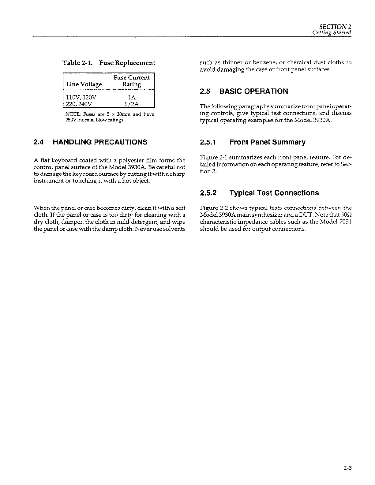
Table 2-1. Fuse Replacement
mi
NCSTE: Fuses are 5 x 20mm and have
25OV, normal blow ratings.
2.4 HANDLING PRECAUTIONS
A flat keyboard coated with a polyester film forms the
control panel surface of the Model 3930A. Be careful not
todamagethekeyboardsurfacebycuttingitwithasharp
instrument or touching it with a hot object.
When the panel or case becomes dirty, clean it with a soft
cloth.
If the panel or cake is too dirty for cleaning with a
dry cloth, dampen the cloth in mild detergent, and wipe
the panel or case with the damp cloth. Never use solvents
such as thinner or benzene, or chemical
dust
cloths to
avoid damaging the case or front panel surfaces.
2.5 BASIC OPERATION
The following paragraphs summarize front panel operating controls, give typical test connections, and discuss
typical operating examples for the Model 3930A.
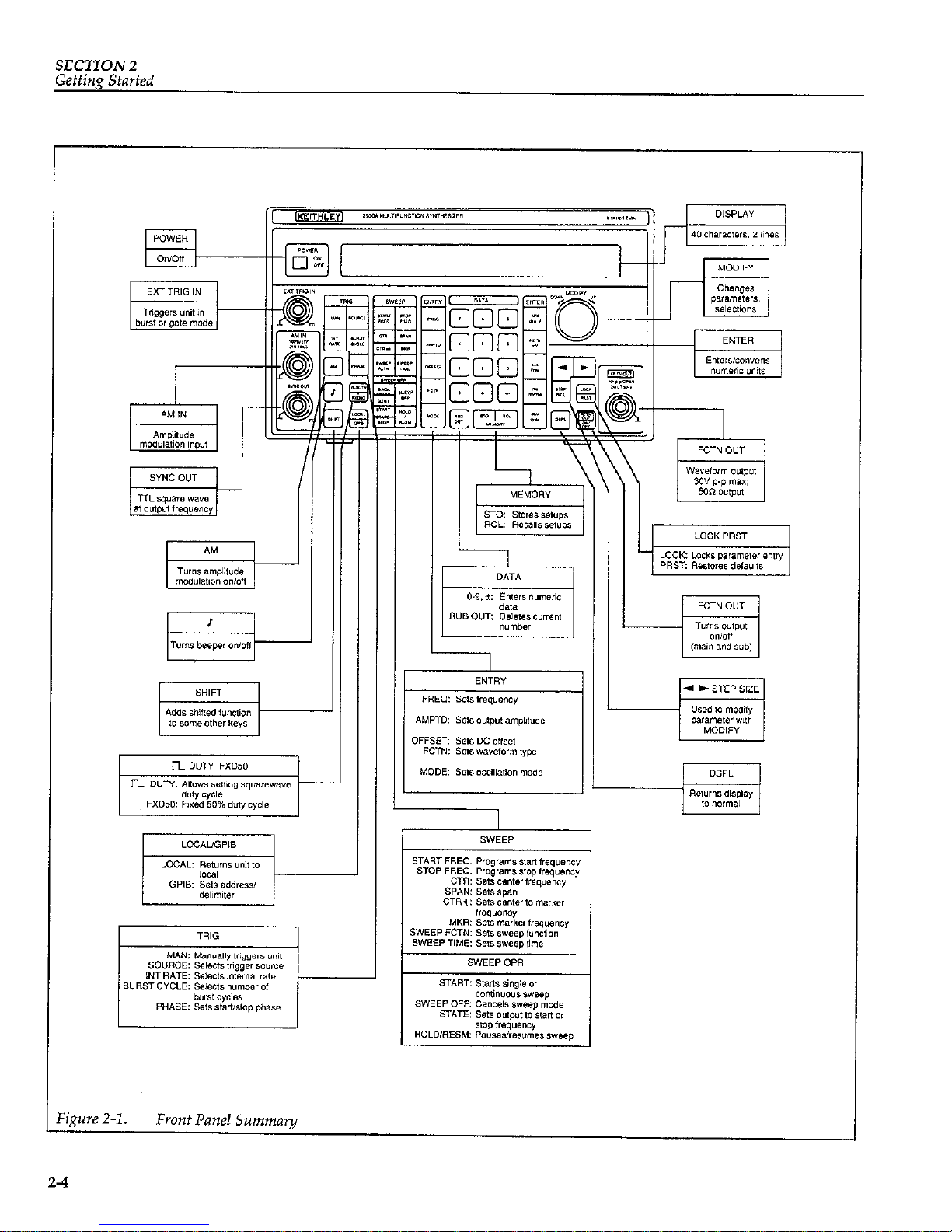
2.5.1 Front Panel Summary
Figure 2-l summarizes each front panel feature. For detailed information on each operating feature, refer to Section 3.
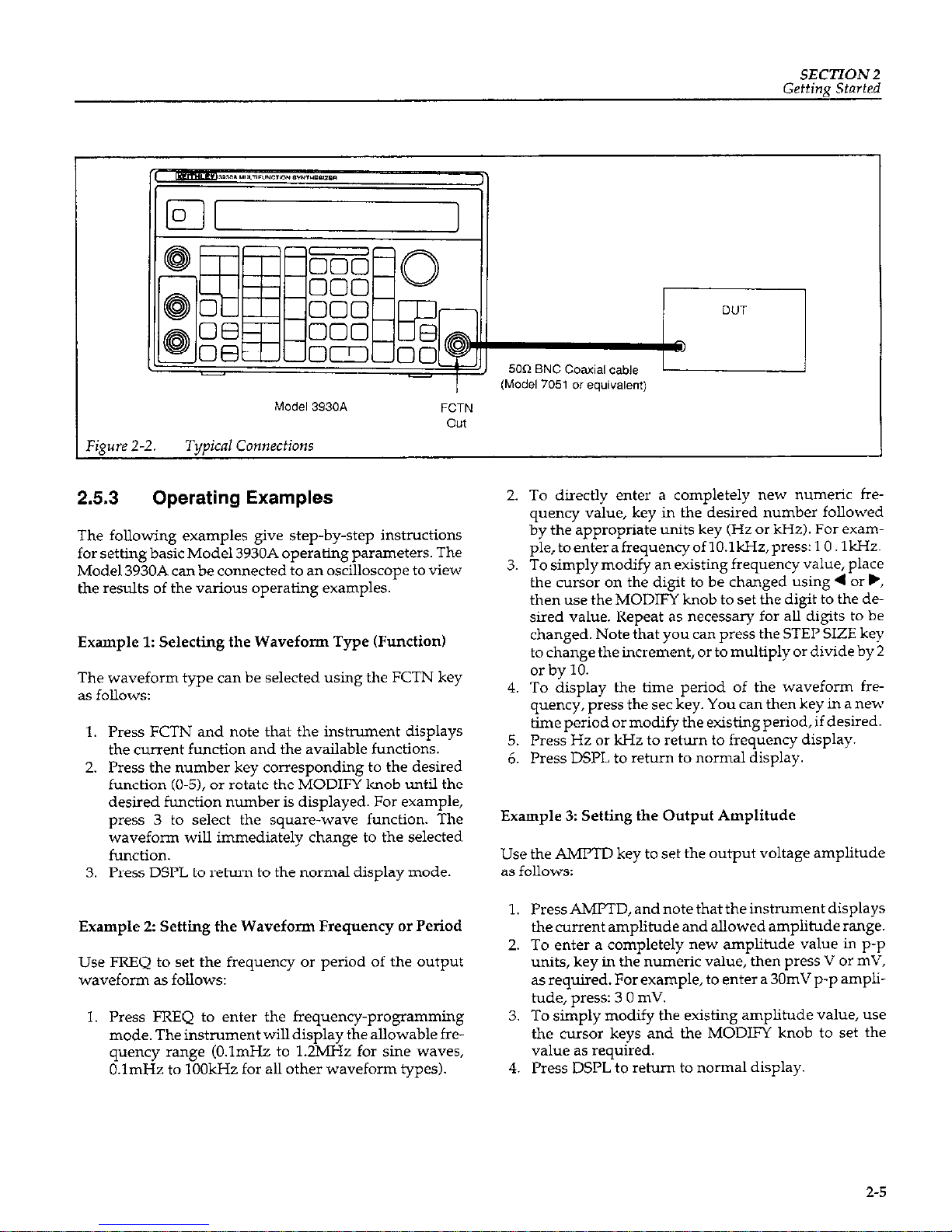
2.5.2 Typical Test Connections
Figure 2-2 shows typical tests comections behveen the
Mode13930A mainsynthesizerand a DLT. Note that SO<>
characteristic impedance cables such as the Model 7051
should be used for output connections.
2-3
Page 17
SECTION 2
Getting Started
r
I
,
igure 2-l.
Front Panel Summary
2-4
Page 18
SECTION2
Getting Started
‘igure
2-2.
Model 3930A
Typical Connections
FCTN
out
2.5.3 Operating Examples
The following examples give step-by-step instructions
for setting basic Model 3930A operating parameters. The
Model 3930A can be connected to an oscilloscope to view
the results of the various operating examples.
Example 1: Selecting the Waveform Type (Function)
The waveform type can be selected using the FCTN key
as follows:
1. Press FCTN and note that the instrument displays
the current function and the available functions.
2. Press the number key corresponding to the desired
function (O-51, or rotate the MODIFY knob until the
desired function number is displayed. For example,
press 3 to select the square-wave function. The
waveform will immediately change to the selected
function.
3. Press DSPL to return to the normal display mode.
Example 2: Setting fhe Waveform Frequency or Period
Use FREQ to set the frequency or period of the output
wavefoml as follows:
1. Press FREQ to enter the frequency-programming
mode. The instrument will display the allowable fre-
quency range (O.lmHz to 1.2MHz for sine waves,
O.lmHz to 1OOkHz for all other waveform types).
2. To directly enter a completely new numeric frequency value, key in the desired number followed
by the appropriate units key (Hz or kHz). For example, toenter afrequencyof lO.lkHz,press: 1 0. 1kHz.
3. To simply modify an existing frequency value, place
the cursor on the digit to be changed using 4 or .,
then use the MODIFY knob to set the digit to the desired value. Repeat as necessary for all digits to be
changed. Note that you can press the STEP SIZE key
to change the increment, or to multiply or divide by 2
or by 10.
4. To display the time period of the waveform frequency, press the set key. You can then key in a new
time period or modify the existing period, if desired.
5. Press Hz or kHz to return to frequency display.
6. Press DSPL to return to normal display.
Example 3: Setting the Output Amplitude
Use the AMFTD key to set the output voltage amplitude
as follows:
1. Press AMPTD, and note that the instrument displays
the current amplitude and allowed amplitude range.
2. To enter a completely new amplitude value in p-p
units, key in the numeric value, then press V or mV,
as required. For example, to enter a 30mV p-p amplitude, press: 3 0 mV.
3.
To simply modify the existing amplitude value, use
the cursor keys and the MODIFY knob to set the
value as required.
4. Press DSI’L to rehun to normal display.
2-5
Page 19
SECTION 2
Getting Started
Example 4: Programming the DC Offset
The OFFSET key allows you to set the DC or average level
of the output waveform, as in the following example:
sweep parameters, while the SWEEP OPR keys control
sweep operation. Perform the steps below to demonstrate basic sweep operation:
1. Press OFFSET, and note that the instrument displays
the current offset value and allowed range.
2. Either key in the desired offset, or use the MODIFY
knob and cursor keys to change the value.
3. Press DSPL to return to normal display.
Example 5: Selecting the Operating Mode
The Model 3930A can be operated in continuous, burst,
or gate modes. The operating mode can be set with the
MODE key as in the following example:
1. Press MODE, and note that the instrument displays
the current mode and available modes (continuous,
burst, and gate).
2. Press the number of the desired mode (or rotate
MODIFY to choose the desired operating mode).
3. Press DSPL to return to normal display.
Example 6: Controlling Sweep Operation
The Model 3930A can be used to sweep across a desired
frequency range. The SWEEP keys allow you to program
Press START FREQ. and key in or use MODIFY to set
the sweep start frequency. For example, press 1 kHz
to program a 1kHz start frequency.
Press STOP FREQ. and set the sweep stop frequency
as desired. For example, to program a 1OkHz stop
frequency, press 10 kHz.
Press CTR and SPAN to view the center and span
frequencies. With 1kHz and IOkHz start and stop
frequencies, the center and span frequencies will be
5.5kHz and 9kHz respectively. NOTE: If you change
the center or span frequencies, the start and stop frequencies willbe automatically changed accordiigly.
Press SWEEP FCTN, and choose the type of sweep.
For example, press 2 to select a linear, ascending
sweep type.
Press SWEEP TIME, and program the sweep time as
required. For example, press 5 set to program a fivesecond sweep time.
To generate a single sweep, press SINGL START.
The unit will generate one sweep based on selected
sweep parameters.
To generate continuous sweeps, press SHIFT START
CONT. The Model 3930A will generate sweeps continuously based on selected sweep parameters.
Press SWEEP OFF to stop a sweep.
2-6
Page 20
SECTION 3
Operation
3.1 INTRODUCTION
This section contains detailed information on front panel
operation of the Model 3930A. For detailed GI’IB
(IEEE-488 bus) operation, refer to Section 4.
3.2 FRONT PANEL AND REAR PANEL
DESCRIPTION
3.2.1 Front Panel Description
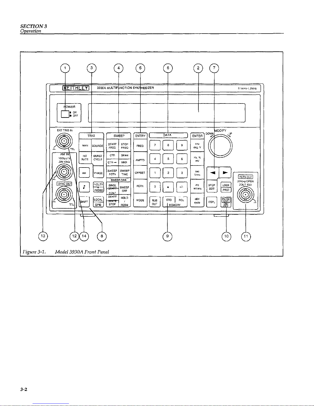
The front panel of the Model 3930A is shown in
Figure3-1. The front panel is made up of a two-line,
40-character liquid crystal display and a control panel
with a built-in flat keyboard. The liquid crystal display
presents information useful for the operation of the
Model 3930A, such as the value of each parameter and
the range of permissible parameter values.
The keyboard includes a SHIFT key, which gives certain
other keys secondary functions. A key which is shaded
with the same color as the SHIFT key requires that you
press SHIFT first before accessing the function of that
particular key.
Most settings are maintained in battery backed-up memory. As a result, the Model 3930A automatically assumes
the previous settings when the power is first turned on.
3-1
Page 21
SECTION 3
Operation
Figure 3-l. Model 3930A Front Panel
3-2
Page 22
SECTION 3
Oaemtion
Key Representations
This section uses special representation such as [SHIFT],
[MODIFY], or [SIZE] in the explanation of certain keys.
This representation indicates the following:
[SHIFT]
[MODIFY]
[MODIFYI [SIZE]
Press the applicable key after pressing the SHIFT key to access the
shifted key function. The liquid crystal display indicates “SHIFT” in the
upper left caner when the Model
3930A is in the shift mode.
Key in the value using the DATA
keys, or change a given setting value
with the MODIFY knob. The up/
down step size when incrementing
or decrementing a value is fixed at 1,
and the cursor position is also fixed.
Key in the value using the DATA
keys, or change a given setting value
with the MODIF? knob. You can
specify the digit to be modified by
placing the cursor on the desired
digit using 4 orb. In addition, you
can change the modify up/down increment using the STEP SIZE key.
Detailed Descriptions
Each front panel feature is described below. The circled
number to the left of each description corresponds to the
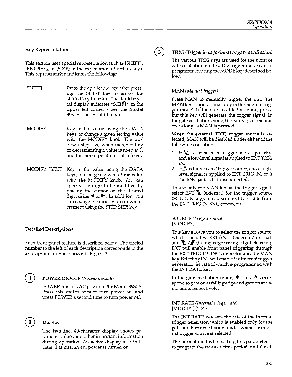
appropriate number shown in Figure 3-1.
POWER ON/OFF @+xuer switch)
POWER controls AC power to the Model 3930A.
Press this switch mce to turn power on, and
press POWER a second time to turn power off.
w Display
The two-line, 40-character display shows parameter values and other important information
during operation. An active display also indicates that instrument power is turned on.
TRIG (Trigger keys
for
burst orgate oscillation)
The various TRIG keys are used for the burst or
gate oscillation modes. The bigger mode can be
programmed using the MODE key described be1OW.
Press MAN to manually trigger the unit (the
MAN key is operational only in the external trigger mode). In the burst oscilLation mode, pressing this key will generate the trigger signal. In
thegateoscillationmode, thegatesigmlremains
on as long as MAN is pressed.
When the external (EXT) bigger scarce is selected, MAN will be disabled under either of the
following conditions:
1. If % is the selected bigger scnme polarity,
and a low-level signal is applied to EXT TRIG
IN.
2. If5 is the selected trigger source, and a highlevel signal is applied to EXT TRIG IN, or if
the BNC jack is left disconnected.
To use only the MAN key as the trigger signal,
select EXT i&L (external) for the trigger smnce
(SOURCE key), and disconnect the cable from
the EXT TRIG IN BNC connector.
SOURCE (Trigger sources
[MODIFY]
This key allows you to select the bigger source,
which includes EXT/INT (external/internal)
and % /$ (falling edge/rising edge). Selecting
EXT will enable front panel triggering through
the EXT TRIG IN BNC connector and the MAN
key. Selecting INT will enable the internal tigger
generator, the rate of which is programmed with
the INT RATE key.
In the gate oscillation mode, x and 4 comespend togateonat fallingedgeandgateonatrising edge, respectively.
INT RATE Unternal trigger rate)
[MODIFY] [SIZE]
The INT RATE key sets the rate of the internal
trigger generator, which is enabled only for the
gate and burst oscillation modes when the internal trigger swrce is selected.
The normal method of setting this parameter is
to program the rate as a time period, and the al-
3-3
Page 23
SECTION 3
Operation
lowed rate ranges from 0.001msec (lpsec) to
2,999.9sec. You can also set the rate as a frequency, in which case the allowed frequency
range is from 0.0004Hz to lOOO.OkHz. When the
rate is programmed as a frequency, the actual
rate is set by rounding the reciprocal of the given
frequency to the value closest to the allowed period (the reciprocal is truncated to eliminate the
portion below the resoluiion). As a result, setting
the rate as a frequency may result in significant
errors when the reciprocal of the frequency is
very small. For example, entering frequencies of
either lOOO.OkHz or 6OO.OOkHz results in a
O.OOlmsec period.
BLJRST CYCLE (Number
of
burst cycles)
[MODIFY] KXZEI
The BURST CYCLE key allows you to program
the number of burst cycles, which defines the
number of waveform cycles generated in the
burst oscillation mode. The allowed range of settings is from 1 cycle to 65,536 cycles. To use burst
oscillation, select the burst oscillation mode with
the MODE key.
PHASE Wart/stop phase)
[MODIFY] [SIZE]
The PHASE key allows programming of the
start/stop phase setting for the burst or gate oscillation modes. The allowed phase range is from
-360.0” to 360.0” with 0.1” resolution.
When the Model 3930A is used with the optional
Model 3933A Phase Shifter to form a multiphase
oscillator, the phase setting is the phase offset for
the Model 3933A.
NOTE
In the burst or gate oscillation modes, oscillation may be unstable if the next trigger is applied at approximately the same time the previous oscillation cycle ends. In this situation,
set the Model 3930A temporarily to another
oscillation mode, then return it to the desired
mode. Doing so willrestorenormal operation.
SWEEP (Frequency sweep keys)
The various SWEEP keys are used to program
sweep functions such as start and stop frequency, center and span frequencies, and sweep
3-4
function and sweep time. The paragraphs below
summarize the operation of these keys. Refer to
the specifications located in Appendix B for details on the sweep range.
Note that frequency parameters can also be set
using waveform period. See the discussion on
the ENTRY keys (
0
5
) for information on fre-
quency and period setting.
START FREQ (Start frequency)
[MODIFY] [SIZE1
The START FKEQ key allows you to set the start
frequency of the frequency sweep. You can specify a start frequency that is either higher or lower
than the stop frequency. The relationship between the start and stop frequency values determines the sweep direction. If the start frequency
is higher than the stop frequency, the sweep will
be performed in a descending direction. If the
start frequency is lower than the stop frequency,
the sweep will be performed in the ascending di-
ECtiOll.
If the start frequency is changed, the sweep
range will be determined by the new start fre-
quency and the current stop frequency.
STOP FREQ (Stop frequency)
[MODIFY] [SIZE]
The STOP FREQ key allows you to set the stop
frequency of the frequency sweep. You can specify a stop frequency that is either higher or lower
than the start frequency. If the stop frequency is
higher than the start frequency, the sweep will
be performed in ascending order. If the stop frequency is lower than the start frequency, the
sweep will be performed in descending order.
Ifthestopfrequencyischanged,thesweeprange
will be determined by the new stop frequency
and the current start frequency.
CTR (Center frequency)
[MODIFY] [SIZE]
The CTR key allows setting of the center frequency of the frequency sweep. The center frequency is specified as the center frequency for
the linear scale, and is not the sweep time basis
center frequency for LOG sweep.
Page 24
SECTION 3
Oaeration
The relationship between the current start and
stop frequency values determines the sweep di-
rection.
If the
center
frequency is changed, the
start and stop frequencies will be changed, but
the span frequency will remain constant, and the
sweep direction will remain unchanged.
The CTR4 key substitutes the marker frequency
for the center frequency. The span frequency is
affected in the same manner as when using the
center frequency setting. If the substituted
marker frequency is different than the center frequency, the start and stop frequencies will
change accordingly.
SPAN (Frequency span)
[MODIFY] [SIZE]
This key allows you to set the frequency span of
the frequency sweep. The relationship between
the start and stop frequency values determines
the sweep direction. If the frequency span is
changed, the start and stop frequencies will be
changed so that the sweep range is determined
by the new frequency span and the current cen-
ter frequency, which will not change.
MKR (Markerfrequency)
[SHIFT], [MODIFY] [SIZE]
This key alkws you to set the marker frequency
of the frequency sweep. Note that you can specify only one marker frequency. While the oscillation frequency is higher than the programmed
marker frequency during a sweep, the marker
output signal available at the rear panel MKR
OUT jack will be set low. The marker output signal will be set high at all other times.
SWEEP FCTN &ueep function)
[MODIFY]
The SWEEP FCTN key allows you to select the
sweep function. Available sweep functions include: step (I,, linear triangular wave and saw-
toothwave (A cd 1, and log triangular wave
or sawtooth wave (A orA 1.
With the step sweep function, the output fre-
quency simply changes between the start frequency and stop frequency at intervals determined by the sweep time. With the linear and log
functions, the frequency increases or decreases
linearly or logaxithmically, respectively.
SWEEP TIM!2 iSweep time)
[MODIFY] [SIZE]
The SWEEP TIME key allows you to set the
sweep time, which is the time period from the
start frequency to the stop frequency. The allowed sweep time range is from 5msec to
9,999sec. For log sweeps, the minimum sweep
time is 5.16msec per decade.
SWEEP OPR (Sweep Operation)
SlNGL START (Single start: singie-sweep
stortJ
This key starts a single sweep. Only one sweep
per key press will be generated.
CONT START (Continuous start: repeated sweep
start)
[SHIFT]
This key starts repeated sweeps, which will be
generated continuously until halted with the
HOLD or SWEEP OFF keys.
SWEEP OFF (Sweep ofl
SWEEP OFF cancels the sweep mode. The oscii-
lation frequency remains at the current frequency when this key is pressed, and the MKR
OUT, SWEEP SYNC OUT, and X DRIVE OUT
signals on the rear panel are set to high level,
high level and OV, respectively.
START STATE Gtart state:
start fre9uency
output)
This key resets the sweep and sets the output fre-
quency to the start frequency.
When START STATE is pressed, the MKR OUT
and SWEEP SYNC OUT signals on the rear pane1
are set high. The X DRIVE OUT signal is set to OV
when the start frequency is lower than the stop
frequency; the X DRIVE OUT signal is set to 1OV
when the start frequency is higher than the stop
3-5
Page 25
SECTION 3
frequency. These signals can be used for scale ad-
justments of XY recorders.
STOP STATE (Stop frequency outputi
[SHIFT1
STOP STATE performs the opposite function of
the START STATE key in that it sets the output
frequency to the stop frequency.
When STOP STATE is pressed, the MKR OUT
and SWEEP SYNC OUT signals on the rear panel
are set high. The X DRIVE OLIT signal is set to OV
when the start frequency is higher than the stop
frequency; it is set to 1OV when the start frequency is lower than the stop frequency.
HOLD/RESM (Hold/resume: temporary sfop and
resume)
This key alternately stops and resumes the
SW-?+
Pressing HOLD/RESM while sweep is in pro-
gress will halt the sweep with the frequency,
MKR OUT, SWEEP SYNC OUT, and X DRIVE
OUT signals present at that time maintained at
their present values. Pressing HOLD/RESM
with the sweep halted resumes the sweep with
signal conditions previously present maintained.
ENTRY (Main parameter setting keys)
FREQ &quency)
[MODIFY] [SIZE]
The FREQ key allows you to set the output fre-
quency of the unit. The allowed frequency range
is between O.OOOlHz and 1,ZOOkHz (l.ZMHz) for
the% and n
waveforms (with50% fixed duty
cycle); the range is from O.OOOlHz to 1OOkHz for
all other waveforms. Note that the 1OOkHz restriction for the n waveform applies only with
a variable duty cycle; you can set the frequency
to amaximumof l,ZOOkHzwitha50% fixedduty
cycle. Also, you can set the frequency to a maxi-
mum of 1,ZOOkHz with the 2/ , /l , and \
waveforms if the quality of the waveform is unimportant.
The oscillation frequency can be programmed in
frequency units or time period units. The al-
lowedrangeforperiodunitsisfrom0.00084msec
to lO,OOO.Osec (1,ZOOkHz limit) or from
0.01000msec to 10,000.0sec (100kHz limitation).
For period-based settings, the frequency is set to
the value of the reciprocal that is rounded to the
nearest number below O.lmHz. Therefore, period-based setting will cause significant errors
when the number of digits for the value of the reciprocal that is rounded is small. For example,
values of either lO,OOO.Osec or 6,000.OOsec will re-
sult in a frequency of O.OOOlHz.
If you press FREQ during sweep operation or
during sweep hold, the current frequency willbe
displayed, but you will not be able to change the
frequency.
Note that the phase of the waveform is continuous even when the frequency is changed.
AMFTD (Amplitude)
[MODIFY] [SIZE]
Pressing AMPTD allows you to set the output
amplitude of the unit. The allowed amplitude
when the DC offset is OV ranges from 0.3OmVp-p
to 3O.OOVp-p when the output range mode is set
to automatic (AUTO), or from OV to 3O.OOVp-p
when the output range mode is fixed (FXD).
When the DC offset is not OV, the upper and
lower limits are restricted (see specifications in
Appendix B). The values for the amplitude setting are for no-load (open) output conditions.
When the output range mode is AUTO, the amplitude setting can be specified using rms or dBV
units in addition to using p-p units. You can
specify the appropriate units by pressing the appropriate ENTER units key when entering the
amplitude. Use mV or V for p-p values, mVrms
or Vrms for rms values, or dBV for dB values.
Note that p-p values are the only permissible
units for DC waveforms, and that the p-p value
varies from one waveform to another if you specify the amplitude as an rms or dBV value. Also
note that the amplitude set by the AMPTD key is
the amplitude of an AC waveform. Set the amplitude of a DC waveform type with the OFFSET
key.
OFFSET (DC offseti
[MODIFY] [SIZE]
The OFFSET key enables DC offset voltage programming. The allowed offset is between -15V
and 15V for a DC waveform. For other waveform
Page 26
SECTION 3
Operation
types, the offset range is restricted to the values
given in the specifications (Appendix B and
paragraph 3.5.7). All specified offset ranges are
for no-load (open-circuit) conditions.
FCTN (Function: waveformi
[MODIFY]
This key allows you to choose the output
waveform. Available waveforms include: DC,
SIN (sine wave), 2/ (triangular wave), L
(square wave), n (ascending sawtooth wave),
and\ (descending sawtooth wav4.
When the output range mode is AUTO, and the
waveform function is changed, the amplitude of
the new waveform is automatically changed to
p-p units, unless the new waveform is DC. For
details, refer to paragraph 3.5.8 in Section 3.
MODE (Oscillation mode)
[MODIFY]
The MODE key programs the oscillation mode
setting. Available oscillation modes include:
CONT (continuous oscillation), BRST (burst oscillation), and GATE (gate oscillation). Refer to
paragraph 3.5.9 for details in Section 3.
DATA (iVumeric keys for parameter ent$
The DATA key set consists of numeric keys for
entering a value and ENTER (units) keys for setting the units of the entered value. The. (decimal
point) key and the +/- (sign inversion) key do
not affect parameters for which they have no
function.
Parameters that are selected with one numeric
character, such as waveform function and oscil-
lation mode, do not require that any ENTER key
be pressed. Such parameters are set simply by
entering one numeric character (or by rotating
the MODIFY knob as required).
For other parameters, enter the required value
with the numeric keys, then press the appropri-
ate ENTER units key. If you enter the incorrect
value, press the RUB OUT (delete) key. RUB
OUT deletes the numeric character or decimal
point from the rightmost position. To delete the
entire entered value and return the display to the
current value, press the original function key to
enable parameter entry for that function.
For frequency and amplitude where parameters
can be entered in different types of units, select
the appropriate units key from the ENTER keys
to complete entry of the value. Use the deg, %, or
cycle keys to enter phase, duty cycle, or burst cycles respectively.
The units keys also have a units-conversion
function. This feature is available for unit conversions such as frequency-to-period conversion
for frequency, as well as amplitude p-p/m/
dBV conversions. When the units key is pressed
with the current setting displayed, the display
will be changed to reflect the newly-selected
units; note, however, that the actual output remains unchanged.
0 (Outpui range mode.,
~S~l,
[MODIFY1
Pressing SHIFI 0 enables output range mode selection and allows you to choose between automatic (AUTO) and fixed (FXD). For complete de-
tails on output range modes, refer to paragraph
3.5.12 in Section 3.
MODIFY (Modifij operation keys)
In addition to using the numeric keys, you can
set any parameter except the GPIB address, delimiter, and memory number by using the MODIFY knob. The MODIFY knob is operational
when the Model 3930A is in the appropriate parameter-entry mode, and the unit displays the
current parameter value.
MODIFY (Modify knob)
When the step size is +1 or ti, you can select the
digit to increase or decrease by 1 or by 5 by placing the cursor under the appropriate digit (use4
or b ) and turning the MODIFY knob to the right
or left.
When the step size is x+2, you can divide the se-
lected parameter by 2 by turning knob counterclockwise, or multiply the parameter by 2 by
turning the knob clockwise. Similarly, when the
step size is x+10, you can divide or multiply the
parameter by 10 by rotating the knob counterclockwise or clockwise respectively. Note that
3-7
Page 27
SECTIOhr 3
the cursor will not be displayed when the step
size is x+2 or x4.10.
This key moves the cursor to the left by one digit
each time it is pressed. Note that cursor will not
be displayed when the step size is x+2 or x+10.
This key mcwes the cursor to the right by one digit each time it is pressed. Note that cursorwilInot
be displayed when the step size is x+2 or x-10.
STEP SIZE W’IDOWN step size)
STEP SIZE changes the MODIFY knob UP/
DOWN step size. For parameters with values
that can be changed using variable step sizes, the
step size will change in the following order each
time this key is pressed: +I i5 x+2 x-10 ___
When the step size is j11 ori5, the digit indicated
by the flashing underline cursor changes by 1 or
by 5 when the MODIFY knob is rotated. When
the step size is x+2 or x+10, the cursor disappears, and the entire display value can be divided or multiplied by 2 or by 10 by rotating the
MODIFY knob.
Miscellaneous Keys
AM (Amplitude modulation)
[MODIFY]
The AM key allows you to turn amplitude
modulation on or off (l= on; O=off). Note that the
modulation signal is applied to the front panel
AMIN BNC jack. When the modulation signal is
OV, or when the modulation depth is 0%, turning
on amplitude modulation reduces the p-p amplitude of the output waveform to one-half its normal value (the value when amplitide modulation is turned off). The output amplitude is the
normal, displayed amplitude value when the
modulation depth is 100%. Refer to paragraph
3.5.6 for more information.
r (Beep sound)
[MODIFY]
This key controls the beep that sounds when you
press front panel keys and when errors occur.
You can turn the beep OFF (0) or ON (1).
n DUTY (Squaw-wave duty cyclei
[MODIFY1 [SIZEI
The n DUTY key allows you to program the
square-wave duty cycle. The allowed duty cycle
ranges from 5.0% to 95.0%.
Two duty-cycle modes are available: 50% fixed
and variable. In the variable mode, the upper fre-
quency limit for square waves is restricted to
1OOkHz even if the duty cycle is set at 50%. Refer
to paragraph 3.5.8 for details.
FXD50 (Fixed 50% duty cycle)
IsKIm
This key fixes the square-wave duty cycle at 50%.
The upper frequency limit for square waves is
1.2MHz when the duty cycle is fixed at 50%. See
paragraph 3.5.8.
SHIFT
The SHIFT key adds a secondary function to
many other front panel keys. Those keys that
have shifted functions have those functions represented on the lower part of each key using the
same color as the SHIFT key. Keys with shifted
functions in&de CTR 4 , MKR, GPIB, FXDSO,
and PRST.
When
the SHIFT key is first pressed, the unit enters the shift mode, and the liquid crystal display
indicates “SHIFT” in the upper left corner. The
shift mode is canceled when any key including
the SHIFT key is pressed (if a key with a shift
function is pressed, the unit enters that mode;
otherwise, it returns to the mode it was in before
SHIFT was pressed).
LOCAL (Return to locnl)
LOCAL cancels remote and returns the instru-
ment to thelocalmodewhenusedovertheGPIB.
When the instrument is in remote (as indicated
by “RMT” in the upper left comer of the display),
parameter setting is disabled, but you can still
display parameters by pressing appropriate
front panel keys.
3-8
Page 28
SECTION 3
OptWi0n
GPIB (GPIB Address: GLIB address, delimiter)
[SHIFT]
The GPIB key allows you to program the GPIB
primary address and the output delimiter used
when the Model 3930A is acting as a GPIB talker.
Only the numeric keys can be used for setting
these parameters (the MODIFY knob cannot be
used). The allowed range for the primary address is from 0 to 30, and the delimiter can be selected for CR/LF or CR (CR and LF or CR only).
The GPIB primary address is the integer part of
this parameter, and the delimiter is defined by
the fractional part. For example, a parameter of
2.0 indicates a primary address of 2 and defines
CR/LF as the delimiter. Similarly, a parameter of
4.1 indicates a primary address of 4 with CR as
the delimiter.
To change only the primary address, enter only
the integer part of the number; the delimiter will
remain unchanged. To change only the deliniter, enter the decimal point followed by the fraction (0 or 1); the primary address value will remain unchanged.
When programming the primary address and/
or delimiter, remember that you must press any
one of the ENTER keys to complete the entry
process.
63
MEMORY (Memory operation keys)
The MEMORY keys allow you to store and recall
instrument setups. Ten units of memory, numbered 0 through 9, are available for setup storage.
ST0 (Store: store setup in
memoy)
The ST0 key stores the current instrument setup
parameters in the selected memory location
(O-9). You can use only numeric keys to store setups (the MODIFY knob cannot be used). l’ressing the numeric key will immediately store the
current parameter values and erase the previous
setup in the selected memory location.
RCL (Recall: wad setup from
,,WXOnJ)
RCL reads instrument setups from the desired
memory location (O-9). You can use only numeric
keys for selecting memory locations to recall (the
MODIFY knob cannot be used). Pressing the nu-
merit key will immediately read the contents of
the selected memory location and will change
the current instrument settings accordingly.
Refer to paragraph 3.512 for additional information on instrument settings after memory recall.
Additional Keys
LOCK (Lock out front panel keys)
This key allows you to disable parameter setting
via most front panel keys. Available modes are
ON (1) and OFF (0). When the lock is ON, the parameters associated with most front panel keys
cannot be programmed, and the corresponding
operating modes cannot bc changed. Ho\ve\-cr.
LOCK, DSPL, and FCTX OUT O-S/OFF are still
operational when the lock is ON. In addition,
trigger input and sweep control input from ap-
propriate BNC connectors are still enabled.
current parameter values such as frequent); can
be displayed by pressing appropriate keys when
the lock is ON. The liquid crystal display Ivill indicate “LOCK” in the position where the modification step size is normally indicated. Also, parameter names will not flash, and the cursor x\:ill
not be displayed.
PRST U%eset)
[SHIFT]
The PRST key recalls the factory default preset
operating parameters.Refer to the specifications
in Appendix B for a summary of preset parame-
ter settings.
DSPL (Main parameter display)
DSPL displays the followingmainparameters si-
multaneously: Signal output ON/OFF (blank for
ON), frequency, amplitude, amplitude modula-
tion mode (AM for on, blank for off), DC offset,
waveform function, oscillation mode, and sweep
mode (blank for normal oscillation). Note that
parameters cannot be programmed from the
main parameter display; you must press appro-
priate keys before setting parameters.
FCTN OUT ON/OFF 6ignni output ON/OFFI
FCTN OUT turns the output waveform off or on.
Each time this key is pressed, ON/OFF will toggle to the opposite state.
3-9
Page 29
SECTION 3
Operation
0
When FCTN OUT is OFF, the main output signal
is turned off and open-circuited, but the SYNC
OUT signal is not affected and remains on.
The liquid crystal display indicates “OFF” in the
upper left cmner when the Model 3930A is in the
FCTN OUT OFF mode (except in the SHIFT or
REMOTE modes).
Note that the factory default setting for FCTN
OUT is ON at power on.
FCTN OUT (Function output:
wamfom
out-
put)
This BNC jack provides the waveform output
signal. The maximum output voltage range is
U5V/open circuit, and the output impedance is
5on.
SYNC OUT LSynchronous output)
This BNC jack provides a TTL-level square wave
signal at the same frequency as the main function
output waveform. Note that the duty cycle of
this signal is affected by the variable duty cycle
setting when the square-wave function is selected.
AM IN (Amplitude modulation input)
The BNC jack is used to apply an external ampli-
tude modulation signal. 100% modulation occurs with a flV input signal, and the input impedance is 1Ok.Q.
EXT TRIG IN (External-trigger input)
This BNC connector is an input for external TTL-
level signals, which can be used to trigger the
Model 3930A.
EXT TRIG IN is internally pulled up to a high
logic level, which means that the external trigger
input will remain hi h with no input signal connetted. If the EXT $ trigger smxce is selected
with the unit in the gate oscillation mode, the
gate signal will be enabled, and the unit will effectively be in the continuous oscillation mode
with no external trigger input signal applied.
3-10
Page 30
SECTION 3
Operation
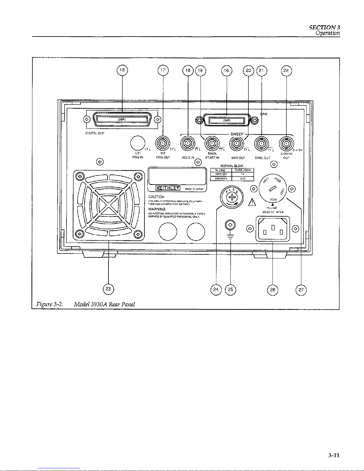
Figure 3-2.
Model 3930A Rear Panel
3-11
Page 31
SECTION 3
Operation
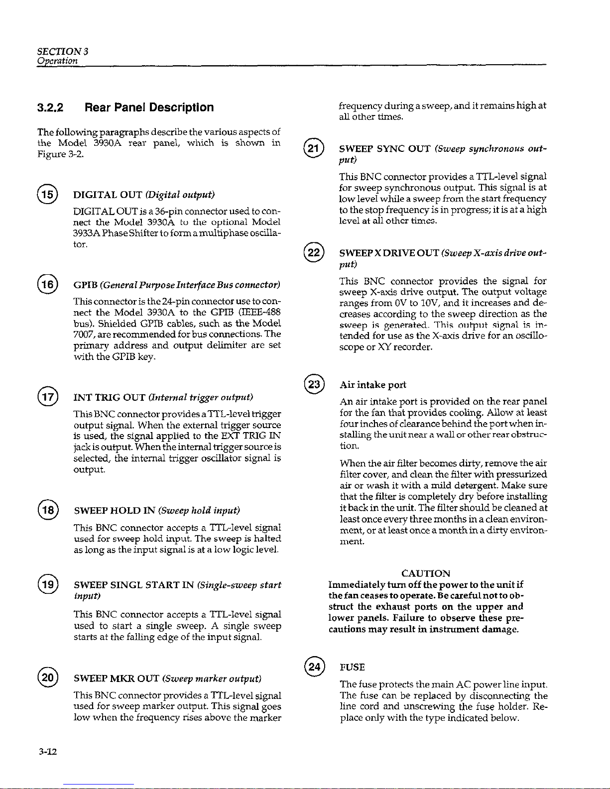
3.2.2
Rear Panel Description
The following paragraphs describe the various aspects of
the Model 3930A rear panel, which is shown in
Figure 3-Z.
DIGITAL OUT (Digital output)
DIGITAL OUT is a 36-pin connector used to con-
nect the Model 3930A to the optional Model
3933A PhaseShifter to form amultiphase oscillator.
GI’IB (General l’zqmse Interface Bus connector)
This connector is the 24-pin connector use to con-
nect the Model 3930A to the Gl’IB (IEEE-488
bus). Shielded GPIB cables, such as the Model
7007, are recommended for bus connections. The
primary address and output delimiter are set
with the GPIB key.
INT TRIG OUT (Internal tri@v output)
This BNC connector provides aTTL-level trigger
output signal. When the external trigger source
is used, the signal applied to the EXT TRIG IN
jack is output. When the internal trigger source is
selected, the internal trigger oscillator signal is
output.
SWEEP HOLD IN (Sweep hold input)
This BNC connector accepts a TTL-level signal
used for sweep hold input. The sweep is halted
as long as the input signal is at a low logic level.
SWEEP SINGL START IN (Single-sweep start
input)
This BNC connector accepts a TTL-level signal
used to start a single sweep. A single sweep
starts at the falling edge of the input signal.
SWEEP MKR OUT &ueep marker output)
This BNC connector provides a TTL-level signal
used for sweep marker output. This signal goes
low when the frequency rises above the marker
0
0
0
frequency during a sweep, and it remains high at
all other times.
SWEEP SYNC OUT (Sweep synchronous out-
put)
This BNC connector provides a m-level signal
for sweep synchronous output. This signal is at
low level while a sweep from the start frequency
to the stop frequency is in progress; it is at a high
level at all other times.
SWEEP X DRIVE OUT (Sweep X-axis drive out-
put)
This BNC connector provides the signal for
sweep X-axis drive output. The output voltage
ranges from OV to lOV, and it increases and decreases according to the sweep direction as the
sweep is generated. This output signal is intended for use as the X-axis drive for an oscilloscope or XY recorder.
Air intake port
An air intake port is provided on the rear panel
for the fan that provides cooling. Allow at least
four inches of clearance behind the port when installing the unit near a wall or other rear obstruction.
When the air filter becomes dirty, remove the air
filter cover, and clean the filter with pressurized
air or wash it with a mild detergent. Make sure
that the filter is completely dry before installing
it back in the unit. The filter should be cleaned at
least once every three months in a clean environment, or at least once a month in a dirty environment.
CAUTION
Immediately turn off the power to the unit if
thefanceasestooperate.Becarefulnotto obstruct the exhaust ports on the upper and
lower panels. Failure to observe these precautions may result in instrument damage.
m
FUSE
V
The fuse protects the main AC power line input.
The fuse can be replaced by disconnecting the
line cord and unscrewing the fuse holder. Replace only with the type indicated below.
Page 32
SECTION 3
Operation
Fuse Current
Line Voltage Rating
llOV, 12OV 1A
22OV, 240V 1/2A
NOTE: fuses are 5 x 20mm and have
zsov, normal blow ratings.
@Q
(Grounding terminal)
The grounding terminal is connected to the chas-
sis of the Model 3930A. To prevent interference
and for safety, be sure to ground this terminal.
WARNING
If the Model 3930A is connected to an ungrounded AC outlet, connect the grounding
terminal to safety earth ground using
#18AWG minimum wire before use.
LINE (Power input connector)
The LINE connector is used to connect the in-
strument to AC power.
WARNING
To avoid the possibility of electric shock,
connect the Model 3930A to grounded AC
outlet using the supplied 3-wire power cord
or the equivalent.
LINE Voltage Selector (Supply voltage switch)
This switch sets the Model 3930A for the correct
line voltage. Using a flat-blade screwdriver, set
the switch in the proper position for the supply
voltage in your area.
WARNING
Disconnect the line cord before changing
setting the switch position.
CAUTION
Operation the Model 3930A on an incorrect
line voltage may result in instrument dam-
3.3 Input and Output Connections
3.3.1
Input Connections
Four signals are applied to the BNC connectors of the
Model 3930A. The specifications of the input signals are
given below.
CAUTION
Be careful not to exceed the maximum allowable input voltages, or instrument damage
may occur.
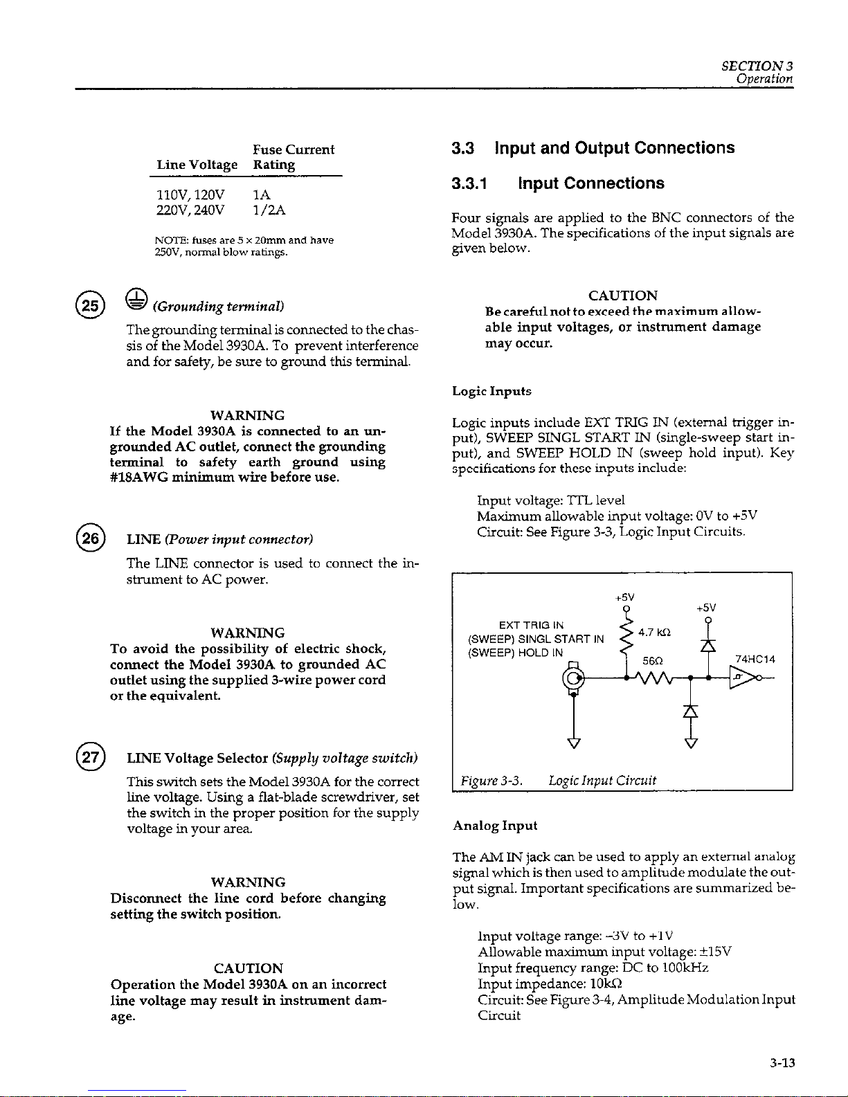
Logic Inputs
Logic inputs include EXT TRIG IN (external trigger in-
put), SWEEP SINGL START IN (single-sweep start in-
put), and SWEEP HOLD IN (sweep hold input). Key
specifications for these inputs include:
Input voltage: l-rL level
Maximum allowable input voltage: OV to +SV
Circuit: See Figure 3-3, Logic Input Circuits.
EXT TRIG IN
(SWEEP) SINGL START IN
(SWEEP) HOLD IN
Figure 3-3. LogicInput Circuit
Analog Input
The AM IN jack can be used to apply an external analog
signal which is then used to amplitude modulate the output signal. Important specifications are summarized be1OW.
Input voltage range: -3v to +lV
Allowable maximum input voltage: ?lSV
Input frequency range: DC to 1OOkHz
Input impedance: 1OkQ
Circuit: See Figure 3-4, Amplitude Modulation Input
Circuit
3-13
Page 33

SECTION 3
Operation
-15v
Figure3-6. Synchronous Output
Figure 3-4.
AmplitudeModulation Input Circuit
3.3.2 Output Connections
Six output signals are available from various BNC connectors of the Model 3930A. The specifications for the
output signals are given below.
CAUTION
Be careful not to connect an external signal to
an output connector, or instrument damage
may occu*.
Logic Outputs
Logic outputs includeSYNC OUT (synchronous output),
INT TRIG OUT, internal trigger output), SWEEP MKR
OUT, (sweep marker output), and SWEEP SYNC OUT
(sweep synchronous output). Specifications for these
outputs are summarized below.
output voltage: TrL level
Circuits: See Figure 3-5, Figure 3-6, and Figure 3-7
+sv
INT TRIG OUT
Figure 3-5. Internal Trigger Output
SYNC OU7
SWEEP MKR OUT
SWEEP SYNC OUT
74F04
Analog Outputs
FCTN OUT (Main Waveform Output)
Maximum output voltage: il5V/open circuit,
+7.5V/5012 load
Output impedance: 5OQ
Recommended load impedance: 50.0 or more
Short circuit protection
SWEEP X DRIVE OUT (Sweep X Axis Drive Output)
output voltage: ov to +lOV (15%)/open circuit
Output impedance: 6OOQ
Recommended load impedance: 1OkQ or more
Output Considerations
All logic outputs are driven by 74F- or 74AC-type logic.
Be careful not to connect a load that results in exceeding
the drive capability of this type of TTL IC. Also, do not
use excessively long connecting cables, as the resulting
capacitance may have detrimental effects on the output
signals.
3-14
Page 34

SECTION 3
Oneration
The internal trigger output UNT TRIG OUT) and synchronous output (SYNC OUT) impedances are matched
at 5OQ at higher frequencies. Relatively good waveforms
will be obtained if 5OQ coaxial cables are used; however,
cables connected to these outputs must not be terminated
with a 50R impedance.
3.
The main waveform output (FCTN OUT) impedance is
5OQ. To maintain maximum amplitude acrc~ss the entire
bandwidth, and for maximum square-wave quality, use
a 5OQ coaxial cable for connections, and terminate the opposite end of the cable with a 50.Q impedance. Note that
the Model 3930A displays voltage amplitude for opencircuit conditions. The actual output voltage with a 500
termination is about half that for no-load conditions
(about 4dB).
3.4 STARTUP
Check that the supply voltage switch is set at the
proper position for the supply voltage. The allowable supply voltage range is UO% of the voltage at
which the supply voltage switch is set.
4.
CAUTION
Operating the Model 3930A in an incorrect
line voltage may result in damage to the unit.
5.
Make sure that the power is off, then plug the supplied power cable firmly into the LINE connector on
the rear panel of the Model 3930k Insert the power
plug into a grounded AC power receptacle.
6.
WARNING
Toavoid thepossibilityof electricshock,use
only grounded AC receptacles for power
connections.
When the power is first turned on, the Model 3930A
will return to the previous settings effective prior to
power-off, and the unit will display the main parameters.
If the previous settings were not stored correctly, the
error code “Er MEMOII” will be displayed, and the
preset settings will be placed into effect. At this
point, main parameters will be displayed, and the
settings prior to preceding power-off will be lost.
This situation occurs when the backup battery used
to maintain memory has insufficient charge, and
stored data cannot be maintained. A fully-charged
battery can retain memory for approximately 60
days. This time period, however, varies slightly with
ambient temperature and from one battery to another. Approximately 50 hours are required to fully
charge a dead battery.
When the battery becomes too weak for practical
use, contact your Keithley representative or the factory for information on obtaining a replacement.
The backup battery may be discharged when the
Model 3930A is used for the first time after being
purchased, or if the unit has not been turned on for a
considerable length of time. Turn the unit on for at
least several hours to charge the battery.
Sweep operation mode parameters are not stored
when the power is turned off. Therefore, turning the
power off during sweep operation, sweep hold, end
of single sweep, start frequency output, or stop frequency output, will result in a sweep-off state the
next time power is turned on.
The function output on/off state is also not saved.
The factory default setting at power-on is function
output on.
If, at power on, the Model 3930A does not enter the
mode with settings that were effective immediately
before previous power-off (or the preset operating
modes), or if the main display does not appear, contact your Keithley representative or the factory to determine the correct ccurse of action.
Turn on Model 3930A power by pressing in on the
front panel POWER switch. Power is ON when the
POWER switch button is depressed (in); power is
OFF when the POWER switch button is released
(out). When the power is turned on, the Model
3930A will begin normal operation, and the liquid
crystal display backlight will turn on.
NOTES:
1. Wait for at least five seconds before turning on the
Model 3930A after huning it off.
2. For precise measurement applications, allow the
Model 3930A to warm up for at least 30 minutes to
allow internal circuits to stabilize.
3-15
Page 35

SECTION 3
Operation
3.5 OPERATING PROCEDURES
3.5.1 Setting Parameters Using Numeric
Keys
When the appropriate parameter key such as FREQ,
AMPTD, OFFSET, or PHASE is pressed, the parameter
name and the present parameter value will be indicated
in the upper part of the liquid crystal display. The allowed range of the parameter setting and useful help information will appear in the lower part of the display.
The parameter value can be changed when the parameter
name indicated in the upper part of the liquid crystal display is flashing. The parameter name will not flash when
the unit is in the GPIB remote mode, or when the front
panel lock is on.
Parameters that are selected by pressing one numeric
character (such as waveform function, oscillation mode,
and trigger source), can be changed simply by pressing
the corresponding numeric key. An error message will be
displayed if the entered value is outside the allowed
range. Other displays and internal settings remain un-
changed when an error occurs.
Example: Changing thewaveform type from the current
%.
(sme wave) ton (square wave) or to 2/ biangular
wave).
Key
Operation Display Result
Press FCTN. Currently selected waveform
(<SIN>l) will be displayed.
Press
3
Waveform changes to <n >3
(square wave).
Press
2
Waveform changes to .2/ >2
(triangle wave).
Parameters that require units, such as frequency, ampletude, and phase, can be changed by entering the new
value with the numeric keys and pressing the appropri-
ate ENTER key to complete the parameter entry process.
While entering the new value, the current parameter
value, unit display, and modification step size will disappear from the display, and the new value will be dis-
3-16
played. To correct an entered value during the entry
process, press the RUB OUT key, which will delete one
character at the rightmost position of the entered nunber. To *e-enter the entire parameter value from the beginning, press the same parameter key to return to the
original parameter setting.
For frequency and amplitude, which have several units
options, select and press the appropriate ENTER units
key to complete the entry process. For phase, burst cycle,
and duty cycle parameters, which have only single parameter units, press the applicable ENTER key to complete entry (deg, cycle, or %).
Regardless of the number of digits for the entered value
and the size of the units (kHz, Hz; set, msec; V, mV; or
Vrms, mVrms), the predetermined number of digits,
resolution, and units will all be properly adjusted and
displayed. When values below the display resolution are
entered with the numeric keys, the value will be rounded
to the nearest whole number and set accordingly.
When inappropriate values are entered, an error message
will be displayed, and the display will return to the preti-
ous value. Internal settings will remain unchanged when
an error condition occurs.
Example: To change frequency from a current value of
1Hz to 2.54Hz. (Correcting an entered value of “2.55”
during entry.)
Key Operation
Display
Press FREQ
Press 2
Press.
Press 5
Press 5
Press RUB OUT
Press 4
Press Hz
Currently selected frequency “1.000
OHz” will be displayed.
The value of the key pressed (2)
will appear.
The decimal point appears to the
right of the 2.
The display now shows “2.5”.
The display indicates “2.55”.
The last 5 is deleted, and the
display reads “2.5”.
The display indicates “2.54”.
Entry is complete, and the display
shows “2.54OOHz”
Page 36

SECTION 3
Oaeration
3.52
Setting Parameters using MODIFY
You can change parameter values with the MODIFY
knob and cursor keys in the following situations:
When the name of the parameter to be changed is
blinking in the upper part of the liquid crystal display.
(The parameter name indicated in the upper part of
the liquid crystal display will not flash when the unit is
in the GI’IB remote mode, or when the keyboard lock
is on.)
If the current value specified is displayed, and the
modification step size is presented in the upper right
comer of the liquid crystal display. (Modification step
size will not be displayed during numeric key input;
modification cannot be performed during numeric in-
put.)
For parameters that are selected with one numeric character (such as waveform and oscillation mode), the flashing cursor is fixed below the numeric character and cmnot be moved. The step size is fixed to fl and cannot be
changed. For parameters that require units (such as frequency and amplitude), the step size can be changed by
pressing the STEP SIZE key.
It is not necessary to use a units key when changing the
value with the MODIFY knob. When modifying an existing value, the modified value will automatically replace
the old parameter value, and the current units will remain unchanged.
When the step size is indicated in the rightmost position
of the liquid crystal display, the step size will change in
the following order each time the STEP SIZE key is
pressed: il i5 x+2 x-10 +1...
Whenthestepsizeisfl or+5,youcanspecifythedigitfor
UP/DOWN adjustment by placing the flashing under-
line cursor under the appropriate digit with the cursor
keys and turning the MODIFY knob to the right or left.
When the step size is x+2 or x+10, the cursor will disap-
pear, and you can multiply or divide by 2 or 10 by turning
the MODIFY knob to the right or left. The step size and
the current cursor position will be stored with the respective parameters when those parameters are stored in
memory.
Changing a value by modification will never result in an
error because the modification process automatically
limits parameter adjustments to the maximum allowed
range for that particular parameter. MODIFY cannot be
used to store or recall memory locations, or to set the
GLIB address and delimiter; only the numeric keys can
be used to program these operating modes.
3.53
Error Codes
When an error cxcus, the Model 3930A displays an error
code in the upper right corner of the liquid crystal display, and the unit generates a long beep sound (if the
beep sound setting is on). The Model 3930A then displays
the current specified parameter value.
Displayed error codes and their meanings are summarized below. The error number at the end of each code
corresponds to the GPIB error code returned with the
“?ERR” inquiry
Er GI’IBOO
The Model 3930A received a non-recognizable programming or inquiry command over the GPIB.
Examples:
“ABC 2”: Non-recognizable programming com-
mand is given.
“?ABC”: Non-recognizable inquiry command is
given.
“123.4”: Parameter values are given without head-
ers.
The Model 3930A received a command that is not recognized in the current mode.
Examples:
Frequency setting command is given during sweep
operation.
The Model 3930A received a command string that is
beyond the capacity of the GPIB input buffer.
Er UNIT01
. You attempted to specify an incorrect parameter unit
Examples:
You pressed the dBV key while programming fre-
quency
3-17
Page 37

SECTION 3
Operation
You pressed the Vrms key while setting the offset voltage.
l You attempted to select an unacceptable unit for other
settings.
Example:
You attempted to specify an amplitude value other
than p-p for a DC waveform type.
l When the output range mode is fixed, you attempted
to set the amplitude using other than p-p units.
Er FREQ02
You attempted to specify a frequency setting outside
the range of O.OOOlHz to 1,ZOOkHz.
You attempted to specify a period setting outside the
allowed range of 0.00084sec to 10,OOOsec.
You attempted to specify a sweep start, stop, center,
span, or marker frequency or period parameter outside the allowed range.
You attenipted to specify a value that causes the re-
sulting start or stop frequency to exceed the allowed
sweep center or span frequency (period) range.
Er PHAS03
l You attempted to specify aphasesettingvalue greater
than &360’.
Er AMPTO
You attempted to specify an amplitude setting outside
the range of 03OmVp-p to 3O.OVp-p (AUTO output
range mode) or O.OOVp-p to 3O.OOVp-p (FXD output
range mode).
When setting the amplitude using other than p-p units
in the AUTO output range mode, you attempted to
program a value outside the f&owing range for the
selected waveform:
s : O.llmVrms to 10.6Vrms, -79.2dBV to 20.5dBV
n :O.l5Vrms to 15.OVrms, -76.5dBV to 23.5dBV
‘G/l,\ :.
0 09mVrms to 8.66Vrms, -80.9dBV to
18.8dBV
Er OFST05
You attempted to specify a DC offset value greater than
*15v.
Er ACDC06
For an AC waveform with a non-zero DC offset, you at-
tempted to specify an invalid amplitude or DC offset
value.
The following restrictions apply when adding DC offset
to the AC waveform:
l AC amplitude setting(Vp-p)/2 +
DC offset voltage setting [VP-p] 2 15V
l When the output range mode is AUTO, the amplitude
setting must be equal to or larger than the minimum
AC amplitude determined by the sum of the voltages
above. In addition, the DC offset must not be added to
limit the above restrictions. See Appendix B and paragraph 3.5.7 for more details on these restrictions.
Er FRDT07
.
You attempted to output square waves with variable
duty cycle at a frequency greater than 1OOkHz.
Examples:
You attempted to change the square-wave duty cycle
from 50% with a frequency greater than IOOkHz and a
n waveform.
You attempted to set the frequency above 1OOkHz
with the unit set to output square waves with variable
duty cycle.
Er SWPO8
l You attempted to perform sweep operations with an
invalid sweep range and sweep time.
Examples:
You attempted to perform a log sweep operation with
the sweep set below one decade.
You attempted to begin a sweep operation with the
sweep start frequency and the sweep stop frequency
set to the same frequency.
You attempted to change the sweep time to 1Omsec
during the execution of a two-decade log sweep.
You attempted to change the sweep time or sweep
span to invalid values during sweep operation.
3-18
Page 38

SEC’ITON 3
Operation
You attempted to set the sweep start frequency and
sweep stop frequency to the same frequency during
sweep operations.
Er RNGE09
You attempted to specify a value outside the predetermined range, resulting in a condition other than errors 0.2
through 08.
Examples:
You entered a value of 6 during waveform selection.
You attempted to set the sweep time to 3msec.
Er CONVlO
The result of the units conversion is outside the allowed
range of the given value. This occurs because of restric-
tions on the number of digits and display resolution and
because of computational errors.
Examples:
You attempted to convert a 0.3OmVp-p value of a sine
wave to rms units. This error occurs because the internal
algorithm converts 0.3OmVp-p to O.lOmVrms, which is
below the lower limit of O.llmVrms.
You attempted to convert an internal trigger rate of
2,999.9sec into frequency units. This error occurs because
the conversion result is O.O003Hz, which is below the
specified lower limit of 0.0004Hz.
Er MEMO11
l An error was found in the backup memory at power-
on for one or more parameter settings. If this error occurs, preset settings will be placed into effect.
l An errc~r was found in the contents of the memory
while recalling parameters. Parameter settings will
not be changed, and the Model 3930A will return to the
prompt for the memory number to recall.
3.5.4 Units Conversion
The Model 3930A can display frequency, rate and amp&
tude in different units. Frequency or rate can be dis-
played as period or frequency, while amplitude can be
displayed in p-p, rms, or dBV units (except in the fixed
output range mode, in which case only p-p units can be
used). You can convert from one type of units to another
by pressing the appropriate units key when the Model
3930A is in the appropriate parameter-setting mode.
Example:
Assume that the Model 3930A is in the frequency-setting
mode and displays a current frequency of 1 .OOO 000 OkHz.
Pressing set or ms converts from frequency to period
units, and the unit displays 1.00000msec.
Note that internal settings remain unchanged when the
units conversion is performed. The Model 3930A automatically displays the result of units conversion as the
current specified value, and you can modify the value using the converted units, if desired.
Frequency Units Conversion
Frequency to period: Press the set or ms key when the
Model 3930A is displaying frequency.
Period to frequency: Press the kHz or Hz key when the
Model 3930A is displaying period.
The actual, specified value is always displayed for the
frequency, and the frequency accuracy specifications
stated in Appendix B apply. However, the period dis-
played is the result obtained by rounding off the reciprocal of a given frequency to the predetermined number of
digits according to the selected resolution (the reciprocal
is truncated for values lower than the resolution), and the
result is displayed. Note, therefore, that the period d&played as the result of units conversion contains a larger
error when the programmed frequency is high.
Example:
Assume that frequency of 1150.000 000 OkHz (actual pe-
riod of 0.00086956msec) is converted to period display.
The value is rounded and displayed as 0.00086msec. The
resultisanerrorequivalent to-1.1% ofthecorrectperiod.
Internal Trigger
Rate
Units Conversion
Period to frequency: Press the Hz or kHz key when the
unit is displaying period.
3-19
Page 39
SECTION3
Operation
Frequency to period: Press the set or ms key when the
Model 3930A is displaying frequency.
The actual, specified value is always displayed for the in-
ternal rate period, and the period accuracy specifications
stated in Appendix B apply. However, the frequency displayed is the result obtained by rounding off the reciprocal of a given period to the predetermined number of digits according to the selected resolution (the reciprocal is
truncated for values lower than the resolution), and the
result is displayed. Note, therefore, that the frequency
displayed as the result of units conversion contains a
larger error when the programmed period is high.
Example:
A rate period of 2,350.Osec is converted to a frequency of
0.0004H2, an error of -6% when compared to the correctly converted frequency
Amplitude Units Conversion
p-p or rms to dBV: Press the dBV key when the Model
3930A displays the p-p or rms value.
p-p or dBV to rms: Press the Vrms or mVrms key when
the Model 3930A displays the p-p or dBV value.
rms or dBV to p-p: Press the V or mVrms key when the
Model 3930A displays the rms or dBV value.
NOTE
Amplitude units conversion is possible only
in the AUTO output range mode. Only p-p
units can be suecified in the FXD (fixed) output range mo&. See paragraph 3..612 for details on the output range mode.
For amplitude, no one-to-one correspondence for actually specified values exists. Because a given value is
rounded off according to restrictions on the number of
display digits and the resolution for each type of units,
the amplitude display may not return to exactly the same
value after conversion from one type of units to another
and back to the original units.
3.5.5 Frequency Programming
Pressing the FREQ key displays the current frequency
and enables frequency programming. (During a sweep
or sweep hold, however, the frequency cannot be pro-
grammed, but the current frequency can still be dis-
played by pressing FREQ.)
To program the frequency using the numeric keys, press
the kHz, or Hz key after entering the value. The resolu-
tion of a frequency value is O.lmHz. When the specified
frequency is below IkHz, the value will be displayed in
Hz units. For 1kHz and above, the frequency will be displayed in kHz units. To specify the frequency in period
units instead of frequency units, press one of the time period keys (set or ms). Frequency programming for sweep
operations is identical.
The allowed frequency range for sine and square waves
(withfixed50% dutycycle)isfromO.OOOlHz tol,ZOOkHz;
for other waveforms, the upper limit is is 1OOkHz for
good quality waveforms. The absolute upper limit for
variable duty cycle square waves is lOOkHz, but the fre-
quency can be set as high as 1,ZOOkHz for 2/,n,and
u
waveforms of reduced quality.
The unit accepts a maximum of six digits and has a resolution of 1Onsec for the frequency parameter. The actual
oscillation frequency is obtained by truncating the reciprocal of the given value to an acceptable number of digits
on the part of the value smaller than O.lmHz.
When frequency programming is enabled, you can
change the present value with the MODIFY knob. The
knob can be used to change the value during both frequency display and period display. When the step size is
il or f5, you can select the digit to change by placing
flashing underline cursor under the appropriate digit
and turning the MODIFY knob to the right or left. When
the step size is x+2 or x+10, the cursor will disappear, and
you can divide or multiple the value by 2 or by 10 by tining the knob to the left or right.
Note that when the displayed period is obtained from a
frequency specified with an insufficient number of digits,
the actual oscillation frequency may not be changed even
if the value is changed with the numeric keys or the
MODIFY knob. The Model 3930A always displays a cor-
rect value for frequency.
3-20
Page 40

SECTION 3
Operation
3.5.6
Output Amplitude and Amplitude
Modulation
Output Amplitude
Pressing =D displays the present amplitude and en-
ables amplitude programming. When using numeric
keys to set the amplitude, press the appropriate units key
to complete the entry process (only p-p units can be specified in the fixed outputrange mode). Press V or mV to enter p-p units, use Vrms or mVrms for rms units, or press
dBV for dBV units. MODIFY can also be used to change
an existing amplitude value.
When the DC offset is OV, the allowed amplitude range is
0.30mVp-p to 3O.OVp-p (AUTO output range mode) or
O.OOVp-p to 3O.OOVp-p (FXD range mode). If, however,
the programmed DC offset is not OV, certain restrictions
concerning the maximum allowable amplitude apply,
and certain combinations of amplitude and offset values
may result in the “Er ACDC06 error”. Paragraph 3.5.7 describes these restrictions in more detail.
In the AUTO output range mode, the amplitude can be
programmed in rms or dBV units. Therms and dBV values are set on the assumption that the average or center
level of the peak-to-peak amplitude of the waveform is
OV. Thus, these values do not depend on the DC offset
value or square-wave duty cycle.
The AMI’TD key sets the amplitude for AC waveforms
only; use the OFFSET key to set the DC output voltage of
the DC waveform type. When the DC waveform is selected, you still can program the amplitude, but that
value can be entered only in p-p units (the allowed amplitude ranges from 0.30mV p-p to 3O.OV p-p, AUTO output
range mode; O.OOV to 3OVp-p, FXD output range mode).
The specified value is stored, and it is used as the given
amplitude for the next selected AC waveform.
Amplitude Modulation (AM)
Pressing the AM key allows you to turn amplitude
modulation on or off (l=ON, O=OFF). You can use the
amplitude modulation function for all waveforms except
DC; however, amplitude modulation is intended primarily for use with sine waves up to 1OOkHz in frequency.
When Ah4 is on, the selected AC output waveform is amplitude modulated by an external signal applied to the
AM IN BNC jack. If the voltage of this modulating signal
is Vm (in volts), the amplitude of the modulated output
waveform is expressed as follows:
Output amplitude+p/rms) =
0.5 x [Displayed amplitude+p/rms):l x (1 + Vm)
The range of Vm is -3V to +lV. When Vm = OV, the out-
put waveform is unmodulated, but the actual waveform
output amplitude is one-half the displayed amplitude.
When Vm < -lV, the output phase is inverted.
100% modulation occurs when Vm = ilV (2V p-p). If a
DC offset of -lV is added to Vm, the carrier is suppressed. If a DC offset of -2V is added to Vm, modulation
occurs with the phase of the output waveform inverted.
3.5.7 DC Offset Programming
Pressing the OFFSET key displays the
current
DC offset
value and enables offset voltage programming.
When using the numeric keys to set the offset, press the V
or mV key after entering the value to complete the entry
process. As with other parameters, you can also use
MODIFY to change an existing offset value.
With a DC waveform, the programmed offset voltage is
the DC voltage value that appears at the output jack.
Valid offset values are within the range of +15V to -15V.
For all AC waveforms, the DC offset is added to the average value of the peak-to-peak amplitude of the AC
waveform. Certain restrictions apply for amplitude-offset combinations, and some combinations of values may
cause an error (Er ACDC06) to occur. Even values that are
valid in a final combination may cause errors when setting up that combination. See Table B-3 (Appendix B) and
Figure 3-8 for relational range restrictions. To prevent errors from occurring while programming amplitude-offset combinations, first set the offset to OV, change the am-
plitude, then set the offset to the desired value. Use
Figure 3-8 as a guide when programming offset and amplitude.
3-21
Page 41
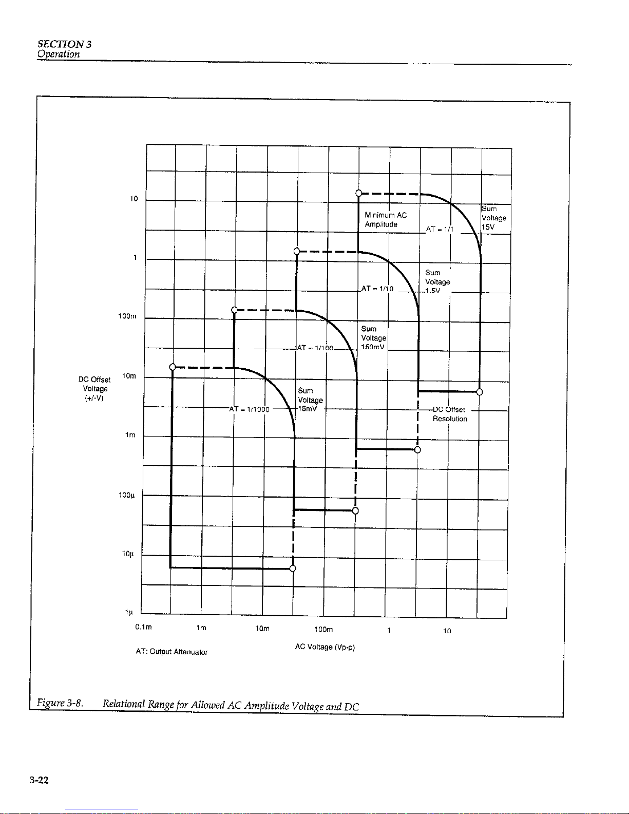
SECTION 3
Operation
I
I
I
I I
I
I
I
I
I
I
I
I
Q
I
I
0
‘&re 3-8.
Relational Range joor Allowed AC Amplitude Voltage and DC
3-22
Page 42
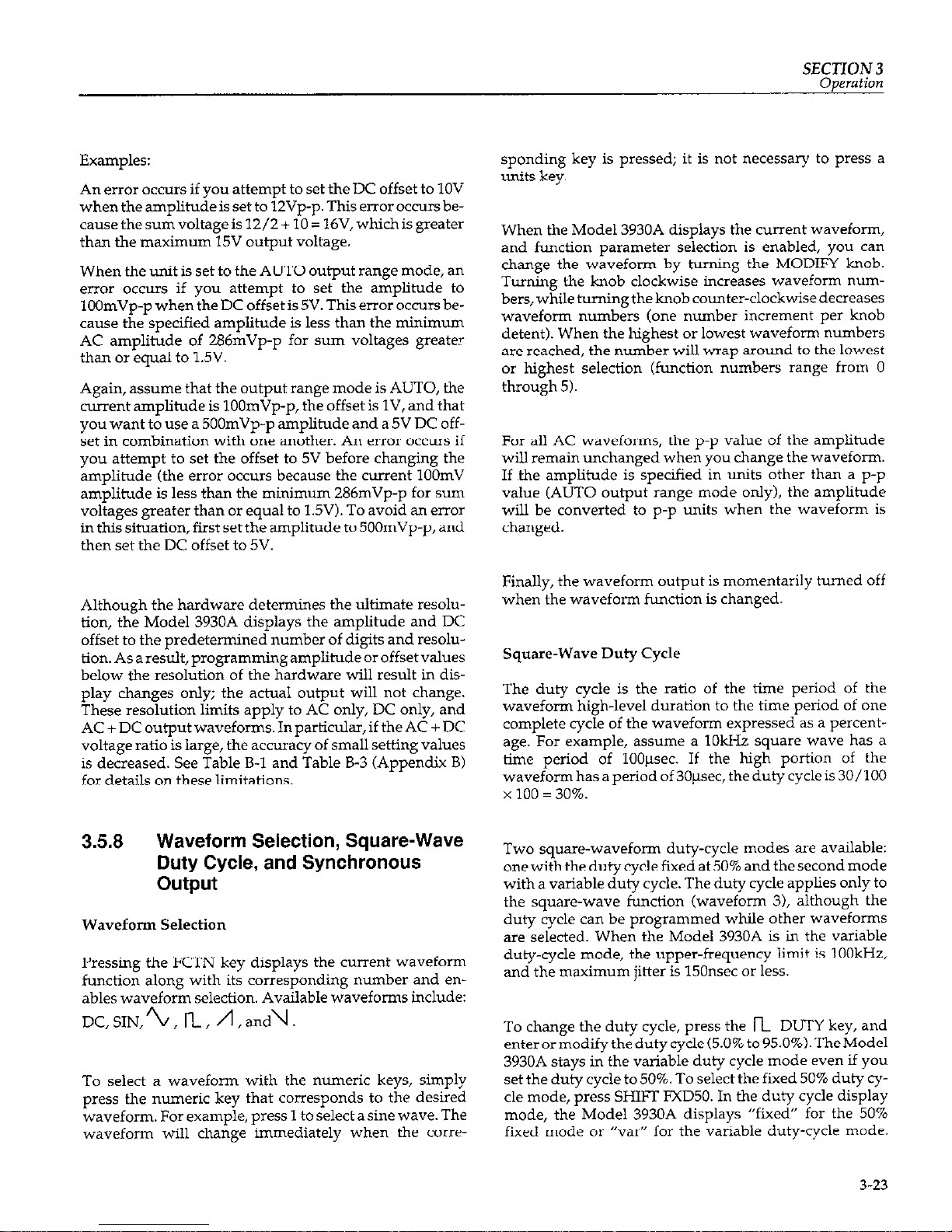
SECTION 3
Examples:
An error occurs if you attempt to set the DC offset to 1OV
when the amplitude is set to lZVp-p. This error occurs because the sum voltage is 12/2 + 10 = 16V, which is greater
than the maximum 15V output voltage.
When the unit is set to the AUTO output range mode, an
error occurs if you attempt to set the amplitude to
lOOmVp-p when the DC offset is 5V. This error occurs because the specified amplitude is less than the minimum
AC amplitude of 286mVp-p for sum voltages greater
than or equal to 1.5V.
Again, assume that the output range mode is AUTO, the
current amplitude is lOOmVp-p, the offset is lV, and
that
you want to use a 500mVp-p amplitude and a 5V DC offset in combination with one another. An error occurs if
you attempt to set the offset to 5V before changing the
amplitude (the error occurs because the current 1OOmV
amplitude is less than the minimum 286mVp-p for sun
voltages greater than or equal to 1.5V). To avoid an error
in this situation, first set the amplitude to 500mVp-p, and
then set the DC offset to 5V.
Although the hardware determines the ultimate resolu-
tion, the Model 3930A displays the amplitude and DC
offset to the predetermined number of digits and resolution.Asaresult,programmingamplitudeoroffsetvalues
below the resolution of the hardware will result in dis-
play changes only; the actual output will not change.
These resolution limits apply to AC only, DC only, and
AC + DC output waveforms. In particular, if the AC + DC
voltage ratio is large, the accuracy of small setting values
is decreased. See Table B-1 and Table B-3 (Appendix B)
for details on these limitations.
3.5.8
Waveform Selection, Square-Wave
Duty Cycle, and Synchronous
output
Waveform Selection
Pressing the FCTN key displays the current waveform
function along with its corresponding number and enables waveform selection. Available waveforms include:
DC,SIN,/G, n, n,and\.
To select a waveform with the numeric keys, simply
press the numeric key that corresponds to the desired
waveform. For example, press 1 to select a sine wave. The
waveform will change immediately when the corre-
sponding key is pressed; it is not necessary to press a
units key.
When the Model 3930A displays the current waveform,
and function parameter selection is enabled, you can
change the waveform by turning the MODIFY knob.
Turning the knob clockwise increases waveform nun
bers, while turningthe knob counter-clockwise decreases
waveform numbers (one number increment per knob
detent). When the highest or lowest waveform numbers
are reached, the number wilI wrap around to the lowest
or highest selection (function numbers range from 0
through 5).
For all AC waveforms, the p-p value of the amplitude
will remain unchanged when you change the waveform.
If ,the amplitude is specified in units other than a p-p
value (AUTO output range mode only), the amplitude
will be converted to p-p units when the waveform is
changed.
Finally, the waveform output is momentarily turned off
when the waveform function is changed.
Square-Wave Duty Cycle
The duty cycle is the ratio of the time period of the
waveform high-level duration to the time period of one
complete cycle of the waveform expressed as a percentage. For example, assume a 1OkHz square wave has a
time period of 100psec. If the high portion of the
waveform has a period of 30psec, the duty cycle is 30/100
x 100 = 30%.
Two square-waveform duty-cycle modes are available:
onewith thedutycyclefixedat50% and thesecondmode
with a variable duty cycle. The duty cycle applies only to
the square-wave function (waveform 3), although the
duty cycle can be programmed while other waveforms
are selected. When the Model 3930A is in the variable
duty-cycle mode, the upper-frequency limit is lOOkHz,
and the maximum jitter is 150nsec or less.
To change the duty cycle, press the n DUTY key, and
enterormodifythedutycycle(5.0% to95.0%).TheModel
3930A stays in the variable duty cycle mode even if you
set the duty cycle to 50%. To select the fixed 50% duty cycle mode, press SHIFT FXD50. In the duty cycle display
mode, the Model 3930A displays “fixed” for the 50%
fixed mode or “vu” for the variable duty-cycle mode.
3-23
Page 43
SECTION 3
Note that the duty cycle setting also changes the duty cyde of the SYNC OLIT signal.
To extend the duty cycle range, use the burst oscillation
mode and one square waveform cycle. Refer to paragraph 3.5.9 for details on setting the oscillation mode.
Synchronous Output
Figure 3-9 illustrates the phase relationship between the
waveform and synchronous output (SYNC OUT) at hequencies below 1kHz. Note that at high frequencies, internal circuit delays result in a substantial phase differential between the waveform output and synchronous output signals.
3.5.9 Oscillation Mode
Oscillation Mode Selection
Pressing the MODE key displays the current oscillation
mode along with its corresponding number and enables
oscillation mode selection. Available oscillation modes
include continuous, burst, and gate modes.
To select the oscillation mode with the numeric keys,
simply press the numeric key that corresponds to the desired oscillation mode. For example press 1 to select the
burst mode. Pressing the numeric key will change the setting immediately; it is not necessary to press a units key
when setting the osc&tion mode.
When the Model 3930A displays the current oscillation
mode, and mode selection is enabled, you can also
change the mode by turning the MODIFY knob. Turning
the knob clockwise increases the oscillation mode number, while turning the knob counter-clockwise decreases
the oscillation mode number (one digit per detent setting). When the highest or lowest mode number is
reached, the number will wrap around to the lowest or
highest value (mode values range between 0 and 2). Note
that the cursor position is fixed, and the step size is fixed
atil.
Continuous Mode
When the continuous mode is selected, the instrument
generates the selected waveform continuously. Triggering is not required, and the selected burst cycle and internal rate parameters have no effect on the output
wavefcmn.
3-24
Page 44

SECTION 3
Operation
I
I
r
Figure 3-9.
Phase Relationship between
Wavefom
and Synchronous Output
3-25
Page 45

SECTION 3
Operation
Burst Mode
In the burst mode, the instrument generates the selected
waveform for the number of programmed burst cycles
(using the BURST CYCLE key) and then stops oscillation
until it is retriggered, either internally or externally, depending on the selected trigger source. During the burst
mode, further triggers are ignored and will not retrigger
the unit.
If the internal trigger source is selected (either INTq or
INTO 1, the on-off burst repetition rate is determined by
the programmed internal rate parameter, which is programmed with the INT RATE key. If the external trigger
source is selected, one burst per trigger is generated. The
external source is either a signal applied to the EXT TRIG
IN jack or the MAN key (the EXT TRIG IN signal can be
used with both EXT 1 and EXT 4 trigger sources, but
the MAN key is operational only for the EXT x source
with EXT TRIG IN high, or with EXT$ and EXT TRIG IN
low).
Figure3-10 shows an example of the burst osciilation
mode. In this example, the unit is set for three burst cycles.
Trigger
signal
Oil
r-l
011
-4
With each trigger, the set
number Of burst
oscillations occurs.
A trigger signal that occurs during
o.scillation is ignored.
Fiaue 3-10. Burst Oscillation Mode Examole
Gate Mode
Inthegatemode,theunitgeneratesoscillationsaslongas
the gate signal (trigger signal) is on. When the gate signal
turns off, the Model 3930A will always stop oscillating at
the end of one complete cycle even if the gate signal turns
off at the mid point of a cycle. Thus, the Model 3930A al-
ways provides integral cycles of oscillation.
With internal trigger source selected, gating is performed
by the internal trigger signal. With an external trigger
source, gating is performed either by a signal applied to
EXT TRIG IN, or by pressing the MAN key.
Figure 3-11 demonstrates the gate oscillation cycle for a
variable-duty cycle square wave. Conditions for this example are: waveform: square, duty cycle: fixed 50%,
burst cycles: 1, start/stop phase: -90”.
Waveform
output
n
r-i
**
Set by osciilation frequency
c-----.....)
Set by internal trigger rate
Duty cycle = (0% f:,,. + 2 ) or (0% cycle + *,
Internal trigger cycle
Figure 3-11. Gate Oscillation Example Using Square
WlZVt?
Figure 3-12 demonstrates how the output waveform al-
ways completes
the current cycle when the gate signal
hums off. -
Oscillates while gate signal is on.
v
(Gate signal)
I
Oscillation cycle always completed.
Figure 3-12. Gate Oscillation Example Showing
Completion
of
Oscillation Cycle
3-26
Page 46

SECTION 3
Operation
NOTES:
In the burst or gate oscillation modes, if the next trigger is applied. at about the same time the unit tern+
nates oscillation, oscillation may become unstable.
In this situation, temporarily change the oscillation
mode, then return the unit to the original mode. Oscillation will ,then return to normal.
If the external, leading-edge trigger source is selected with the unit in the gate oscillation mode, the
gate signal is effectively on, and the unit performs
continuous oscillation if the front panel EXT TRIG
IN connector is left disconnected from an external
trigger signal. This condition occurs because EXT
TRIG IN is internally pulled up to a high logic level,
and the circuit logic level is equivalent to applying a
high input signal when EXT TRIG IN is left disconnected.
You can use the MAN key to manually trigger the
unitin thegateorburst oscillationmodesonlyunder
the follow& conditions
A. If the trigger source is set to EXT x, and EXT
TRIG IN is left disconnected or a high-level signal is applied to this connector.
B. If the trigper source is set to EXT 5. and a low-
level sig% is applied to EXT TRIG k
3.5.10 Trigger Parameters (Source, Rate,
Burst Cycle, and Phase)
Trigger Source
Pressing SOURCE displays the current trigger source
with its corresponding number and enables trigger
source selection. Available trigger sources include external (a trigger signal applied to the EXT TRIG IN jack),
and internal (internal trigger rate generator). Rising-edge
& ) and falling-edge (x ) signals can be selected for both
external and internal trigger sources. Note that selecting
internal trigger automatically selects the internal trigger
generator as the trigger source.
In the gate oscillation mode with the trigger source set to
external 4, the gate signal will be on, and the Model
3930A will oscillate continuously when the EXT TRIG IN
BNC connector iz, left disconnected. This situation is the
result of the internal pull-up resistor connected to the ex-
ternal trigger input. Thus, leaving the external trigger ir-
put connector disconnected is equivalent to connecting a
high logic level.
Internal Rate
The internal rate parameter sets the frequency of the in-
ternal trigger oscillator, which is used to trigger the unit
in the burst and gate oscillation modes when an internal
trigger source is selected. In the burst oscillation mode,
the burst-repetition rate is determined by the internal
rate setting. Similarly, the internal rate parameter sets the
on-off gate frequency in the gate oscillation mode.
In order to program the internal rate parameter, press the
INT RATE key. Theunit will display the present rate, and
you can then enter the value with numeric keys or change
the rate with MODIFY, as desired. The allowable range
for the rate parameter is from O.OOlmsec to 2,999.9%x.
You can also program the rate parameter in terms of frequency. To do so, simply press the kHz or Hz key to complete parameter entry. The allowed range is from
0.0004Hz to l,OOO.OkHz. When setting
the rate as a
frequency, the reciprocal of the parameter is rounded off after truncating the portion below the resolution. As a result, errors become large when the frequency is high.
For
example, values of 1,OOO.O!&Iz and 600.00kHz will both
result in a period of O.OOlmsec.
Burst Cycle
Press BURST CYCLE to program the burst cycle parame-
ter, which sets the number of oscillation cycles the unit
generates each time it is triggered in the burst oscillation
mode. When the unit is in the burst-cycle entry mode,
you can program the value using the numeric keys or
change that value with the MODIFY knob (use the cycle
key to complete entry in the numeric entry mode). The allowable range for the burst cycle parameter is from 1 cycle to 65,536 cycles.
Start/Stop Phase
Pressing the PHASE key displays the current start/stop
phase and allows setting of that phase parameter, which
controls the start/stop phase for the burst and gate ox&
l&ion modes. The allowed range for the start/stop phase
parameter is from -360.0” to 360.0° with 0.1’ resolution.
Phase definitions for the available waveforms are illustrated in Figure 3-13.
3-27
Page 47

SECTION 3
Operation
Square wave with Duty Square wave with
cycle fixed at 50%
variable Duty cycle
T
I
l
j---r--
I
@-----A
I
I
I
(Shaded area is the hysteresis region
which changes to high or low depending
on the phase past value.)
Ascending saWtooth wave
Descending sawtooth wave
?gure 3-13.
Waveforms and Phase Definitions
3-28
Page 48
SECTION 3
Operation
The Model 3930A
generates square waves
with a fixed
50% duty cycle by processing sine waves with a zerocrossing comparator that has hysteresis. The level of the
generated square wave, therefore, alternates high and
low at approximately 0”, +180”, and ti60” (within about
i2.3”) depending on the past value of the phase. Thus, to
set the square-wave start/stop level high, set the phase to
90”. Similarly, the phase should be set to -90’ to set the
square-wave start/stop level low.
The Model 3930A also generates the synchronous output
for the sine, triangle, and sawtooth waves by passing
each waveform through a zero-crossing comparator that
has hysteresis. As a result, the synchronous output level
changes at the same points as the square wave when the
phase is approximately 0”, +180”, or ti60”for the sine or
triangle waves, or about f180” with the sawtooth wave.
When the Model 3930A is connected to the optional
Model 3933A Phase Shifter to form a multiphase oscilla-
tor, the Model 3930A start/stop phase setting is also the
phase offset. Refer to the Model 3933A Instruction Manual for multiphase oscillation phase setting information.
3.5.11 Frequency Sweep Operation
The Model 3930A can be set up to generate frequency
sweeps over a variety of ranges. The following paragraphs discuss the various aspects of programming frequency sweeps. Figure 3-14 shows sweep waveforms.
Setting the Sweep Range
You can set the sweep range in one of two ways: (1) by
setting the start and stop frequencies, or (2) by setting the
center and span frequencies. The actual sweep is generated from the start frequency to the stop frequency, and
the sweep direction is determined by the relative values
of the start and stop frequencies. If the start frequency is
lower than the stop frequency, an ascending-frequency
sweep will be generated. If the start frequency is higher
than the stop frequency, a descending-frequency sweep
will be generated.
If you specify the center and span frequencies to set the
sweep range, the Model 3930A will automatically convert them into start and stop frequencies. See the specifications in Appendix B for more details on the sweep
range and sweep width.
The Model 3930A determines the sweep range as described below when you change a frequency parameter:
When the start frequency is changed:
The stop frequency remains unchanged.
center frequency=
(start frequency+stop frequency)/2
N’ortion of value below O.lmHz is truncated.)
Span frequency = start frequency-stop frequency
When the stop frequency is changed:
The start frequency remains unchanged.
center frequency =
(start frequency + stop frequency)/2
(Portion of value below O.lmHz is truncated.)
span frequency = start frequency-stop frequency
When the center frequency is changed:
The span frequency remains unchanged.
The relationship between the start and stop frequency
value remains the same as it was before the center frequency was changed:
start frequency =
(center frequency 3 span frequency/Z)
U’ortion of value below O.lmHz is truncated.)
stop frequency =
(center frequency + span frequency/2)
(Portion of value below O.lmHz is truncated.)
When the span frequency is changed:
The center frequency remains unchanged.
The relationship between the start and stop frequency
values remains the same as it was before the span frequency was changed:
start frequency =
(center frequency 7 span frequency/2)
(Part smaller than O.lmHz is truncated.)
stop frequency =
(center frequency * span frequency/21
(Part smaller than 0.lmH.x is truncated.)
The start and stop frequencies always correspond to the
opposite ends of the actual sweep range. When the span
frequency is an odd number of O.lmHz units, the displayed center frequency will be 0.05mHz higher than the
3-29
Page 49

SECTION 3
Operation
actual center frequency value. The center frequency is the
center frequency on the linear scale, and it is not the center frequency based on the sweep time in the log sweep
mode.
Sweep Function
Three sweep functions are available: A (ascending, descending),/l (ascending), andI (step). The A sweep
is generated by sweeping from the start frequency to the
stop frequency and then sweeping back to the start fre-
quency. Then sweep is generated by sweeping from the
start frequency to the stop frequency and then returning
to the start frequency instantly. The1 sweep alternates
between the start frequency and the stop frequency.
Sweep Time
Sweep time will vary depending on the selected sweep
function.
When the sweep function is A :
Sweep time = time of transition from start frequency to
stop frequency
= time of transition from stop frequency to start fre9U-7
= half of repetition period of continuous sweep
When the sweep function is n :
Sweep time = time of transition from start frequency to
stop frequency
= repetition period of continuous sweep
When the sweep function is 1:
Sweep time = duration of start frequency in continuous sweep
= duration of stop frequency in continuous sweep
= half of repetition period of continuous sweep
When the sweep times for then and/\ sweep functions
are identical, the sweep rate along the equivalent sloped
portions of the two waveforms will also be identical.
Note, however, that the continuous-sweep repetition period for the two functions is different. See Figure 3-14 for
more details on sweep progression.
Sweep Operations
Model 3930A sweep operations include the following
eight types of sweeps:
Starting a continuous sweep (CONT START key).
Starting a single sweep (SINGL START key).
Holding and resuming a sweep (HOLD/RESM key).
Turning a sweep off to enable normal frequency pro-
gramming (SWEEP OF’F key).
Setting the output waveform to the start frequency
(START STATE key).
Setting the output waveform to the stop frequency
(STOP STATE key).
Starting a single sweep with external signals (SINGL
START IN BNC jack).
Holding and resuming a sweep with external signals.
(HOLD IN BNC jack).
starting a continuous Sweep
To start a continuous sweep, press SHIfl CONT START.
During the sweep, the Model 3930A displays the sweep
frequency, and the following message is displayed:
“CONT SWEEP EXEC (EXIT:SWI’ OFF)“. When the
Model 3930A is in this mode, you cannot set the fre-
quency with the FREQ key.
3-30
Page 50

SECTION3
Operation
3-31
Page 51

SECTION 3
Operation
Starting a Single Sweep
Press the SINGL START key to initiate a single sweep.
During a single sweep, the Model 3930A displays the
sweep frequency, and the following message is displayed: “SINGL SWEEP EXEC (EXITSWP OFF)“. Yoc
cannot set the frequency with the FREQ key while the
unit is generating a single sweep.
When the Model 3930A terminates a single sweep, it displays the terminated sweep frequency along with the following message “SINGL SWEEP END”. Once the sweep
has terminated, you can program the output frequency
with the FREQ key. The MKR OUT and SWEEP SYNC
OUT signals go high, and the X DRIVE OUT signal is set
to OV at the end of the sweep.
Holding/Resuming a Sweep from the Front Panel
To temporarily halt execution of
a continuous or single
sweep, press the HOLD/RESM key. The Model 3930A
stops the sweep operation immediately, and it displays
the frequency at which it stopped the sweep. The MKR
OUT, SWEEP SYNC OUT, and X DRIVE OUT signals
maintain their current values when the sweep is halted.
When a continuous sweep is paused, the Model 3930A
displays “CONT SWEEP HOLD (EXITSWI’ OFF)“; similarly the unit displays “SINGL SWEEP HOLD
(EXITSWF OFF)” when a single sweep is paused. When
the Model 3930A is in the sweep hold mode, you cannot
program the frequency with the FREQ key.
To reame a sweep starting at the frequency at which you
stopped sweep operation, press the HOLDJRESM key
again.
Turning a Sweep Off to Enable Normal Frequency Programming.
Press the SWEEP OFF key during a sweep or sweep hold
to turn off a sweep and enable normal FREQ key programming. The MKR OUT and SWEEP SYNC OUT signals will be set high, and the X DRIVE OUT signal will be
set to ov.
When the SWEEP OFF or FR?ZQ keys are pressed at the
completion of a single sweep, during start frequency output, or during stop frequency output, normal frequency
3-32
programming will be enabled. In addition, the MKR
OUT and SWEEP SYNC OLI? signals willbe set high, and
the X DRIVE OUT signal will be set to OV.
Setting the Output to the Start Frequency
PFSSS
the START STATE key to set the output waveform
to the programmed start frequency. In this mode, the
Model 3930A displays the start frequency along with the
following message: “SWEEP STRT STATE”. The MKR
OLJT and SWEEP SYNC OUT signals also go high during
the start frequency mode. The X DRIVE OUT signal is set
tom OV if the start frequency is lower than the stop frequency; it is set to 1OV if the start frequency is higher than
the stop frequency.
When the Model 3930A is in this mode, pressing the
FREQ key enables normal frequency programming with
the FREQ key and sets the X DRIVE OUT signal to OV.
Setting the Output to the Stop Frequency
Press SHIFT STOP STATE to set the output waveform to
the programmed stop frequency. While in this mode, the
Model 3930A displays the stop frequency along with the
following message: “SWEEP STOP STATE”. During the
sweep stop state, the MKR OUT and SWEEP SYNC OUT
signals are set high. X DRIVE OUT is set to 1OV if the start
frequency is lower than the stop frequency; it is set to OV
if the start frequency is higher than the stop frequency.
When the Model 3930A is in this mode, pressing the
FR!?Q key enables normal frequency programming with
the FREQ key and sets the X DRIVE OLJT signal to OV.
Starting a Single Sweep Using an External Signal
A TTL-level, falling-edge signal, applied to the SINGL
START IN BNC connector, starts a single sweep. This signal performs essentially the same operation as pressing
the SINGL START key.
SINGL START IN is internally pulled up to a high logic
level, and sweep operation is not affected when the this
connector is left disconnected from external signals.
Holding/Resuming a Sweep with
an
External Signal
A ‘ITL low-level signal, applied to the SWEEP HOLD IN
BNC connector, places the Model 3930A in the sweep
Page 52

SECTlON 3
Operation
hold mode. In the sweep execution mode, the Model
3930A halts the sweep as long as this input remains low.
If you attempt to start a sweep when this input is low, the
Model 3930A immediately enters the sweep hold mode.
Note that pressing HOLD/RESM does not resume
sweep operation with the hold signal held low; you must
set SWEEP HOLD IN high to resume the sweep.
SWEEP HOLD IN is internally pulled up to a high logic
level, and sweep operation is not affected when this connector is left disconnected from external signals.
Sweep Frequency and Sweep Output
Figure 3-14 illustrates how the sweep frequency and the
MKR OUT, SWEEP SYNC OUT, and X DRIVE OUT signals change with time.
The MKR OUT signal is high when the sweep frequency
is higher than the marker frequency. When the sweep
function is n or 1, the high signal level is maintained
even after a single sweep is terminated.
The SWEEP SYNC OUT signal goes low during the tran-
sition from the start frequency to the stop tiequency.
When the sweep function is 1, the frequency changes at
the center point of this output signal.
The X DRIVE OUT jack supplies a voltage that varies between OV and 1OV in proportion to the lapse of sweep
time, and according to the direction of the sweep fre-
quency. The X DRIVE OUT signal also varies linearly
with time in the log sweep or step sweep mode.
Substituting Marker Frequency for Center Frequency
Press SHIFT CTRI to set the center frequency to the current marker frequency value. This operation produces
the same result as programming an identical frequency
with the numeric keys. The marker frequency is not affected by this operation.
Changing Settings During Sweep Operation
Because of processing execution time in the sweep execu-
tionmode, theModel3930Amayrespond to the keys and
GPIB commands mcze slowly in the sweep mode than in
other modes. If you change the sweep range, sweep time,
or sweep function with MODIFY while the Model 3930A
is in the sweep execution mode, the unit will recalculate
the new parameters each time you change the setting, resulting in slower response.
If you set the sweep range based on center and span frequencies, an error may occur depending on the order of
parameter selection whether or not the Model 3930A is in
the sweep execution mode.
Example:
To change a SkHz center frequency and an &Hz span fre-
quency to 2kHz and 3kHz respectively, you must first
change the span frequency to 3kHz and then change the
center frequency to 2kHz. If you first change the center
frequency to &Hz, an error will occur because this combination would result in a start frequency of -2kHz.
Number of Steps in a Sweep
Sweep operation of the Model 3930A is controlled by
software. The software determines the number of steps in
a sweep (excluding step sweep) so that the Model 3930A
can perform as smooth a sweep as possible, considering
the processing speed of the microprocessor and the resolution of the synthesizer (O.lmHz).
The number of steps in sweep can be roughly calculated
as outlined below. The number of steps described here is
the number of steps between the start frequency and the
stop frequency when the sweep function 1s
ANA.
Linear sweep steps
Inalinearsweep, thenumberof stepscanbecalculated as
follows:
Number of steps: [Sweep width (Hz) x 10’1 or
[Sweep time (SK) x 20001, whichever is greater.
3-33
Page 53

SECTION 3
If the single-step frequemy increase/decrease width is
equated to the step width, the step width can be represented as follows:
Step Width (Hz) = Sweep lvldth (Hz)
Number of steps
The MKR OUT signal is synchronous with the sweep
steps. With an ascending sweep, the MKR OUT signal is
low when the sweep frequency is equal to or higher than
the marker frequency. With a descending sweep, the
marker output is high when the sweep frequency is lower
than the marker frequency. The deviation between the
set marker frequency value and the actual transition in
the MKR OUT signal is:
Marker Deviation (Maximum): i-Step width (Hz)
TheX DRIVE OUT signal will also change synchronously
as the sweep progresses. Because of the E-bit resolution,
the maximum number of steps is 255, When the number
of sweep steps is less than or equal to 255, the number
sweep steps and the number of X DRIVE OUT steps are
the same.
Log sweep steps
The Model 3930A generates approximately logarithmic
sweeps by overlaying linear sweeps of about l/10 decade.
Number of steps per l/10 decade:
[Sweep
timdsed
x200/sweep width(decade)] or
[dLower limit frequency(Hz) x 501, whichever is smaller.
Number of sweep steps:
Number of steps per 1 /lO decade x sweep widthcdecade)
X10
Marker deviation: zE?.5/number of steps per 1 /IO decade
(%I
In either sweep mode, the frequency at which the marker
output actudy changes does not exceed the range between the specified start frequency and the stop fre
quency. The value always increases or decreases
monotonically.
3.512 Output Range Mode
Output Range Mode Description
Amplitude control for both AC waveforms and DC offset
voltagesisperformedusingbothamultiplyingD/Aconverter and an output attenuator. When the output range
mode is set to AUTO, the output attenuator is controlled
by the amplitude and DC offset values, and the output
voltage is determined both by the multiplying D/A converter and the attenuator. Therefore, the waveform amplitude has 3-digit resolution (VP-p and Vrms values)
and O.ldBV resolution (dBV values), and the DC offset
also has 3-digit resolution. Since an output attenuator is
used, waveform quality (waveform distortion, precision,
and noise) remains high even when the output amplitude is low. Amplitude and DC offset are restricted to a
range that does not exceed 15V cumulative voltage, but
when the amplitude-to-offset voltage ratios become
large, the voltage with the smaller value becomes less
precise. Also, when the output attenuator switches, the
waveform output is momentarily turned off, and the
both the waveform and DC offset voltages are temporarily interrupted.
When the output range mode is set to FXD (fixed), the
output attenuator is fixed at 0 dB, so that the output
changes virtually instantaneously without interruption,
even if frequency, amplitude, and DC offset are changed
(note, however, the output signal is momentarily interrupted for waveform and AM on/off changes). Also, amplitude and DC offset can be independently set to values
not limited by a 15V cumulative voltage value, and am-
plitude can be set to OVp-p. However, amplitude values
can only be set in Vp-p units, and they cannot be converted to Vrms or dBV units. Also, only the A/D converter is used to set the amplitude, so the smaller the setting, the fewer the number of bits that are used for the
value. As a result, and the output waveform quality is re-
duced. Also, although the amplitude can be set to 0 Vp-p,
the actual output may differ somewhat from that value.
This deviation from the ideal OV value tends to increase
as the output frequency increases.
Consequently, the AUTO output range mode is most effective in situations where it is important to have precise
output settings and good waveform quality down to a
low level, and in situations where output changes across
a wide range with similar offset and amplitude levels are
required.TheFXDoutputrangemodeismost effectivein
3-34
Page 54

SECTION 3
Operation
situations where the output (both waveform and DC offset) is relatively constant, or when a large DC offset is
added to a waveform with a small amplitude. FXD is also
a better choice in situations where output values are
changed from 0 to full scale at equal increments.
The relation between setting resolution and number of
digits when the output is AC only (when the DC offset is
0 volts), and when the output is DC only (when the
waveform is DC) in AIJTO/FXD output range modes is
given in Figure 3-15. Figure 3-16 shows the setting resolution and number of digits for DC output values alone.
Output Range Mode Setting
Pressing SHIFT 0 displays the current outputrange mode
setting and allows the mode to be set as desired. The two
output range modes are: AUTO (0) and FXD (1). You can
select the desired mode either by pressing the appropriate numeric key (0 or 11, or by rotating the MODIFY knob.
Note that the amplitude and DC offset setting ranges
vary between the two modes, and that the amplitude and
offset values for each output range mode are independently set and saved. Also, the waveform output is momentarily turned off when the output range mode is
changed.
Memory Recall Operation
The output range mode and respective amplitude and
DC offset values can also be stored in memory, but when
settings are recalled from memory, operation differs depending on the present and recalled output range modes.
When the unit is presently in the ALTO mode, the output
is temporarily turned off, settings stored in rnemo~, are
recalled, and the output is turned on again after sethngs
are recalled. However, if the unit is currently in the
AUTO mode, and the recalled settings include the AUTO
mode, the output waveform will be interrupted by the recall process only if the frequency changes during memory recall.
If the Model 3930A is currently in the FXD mode, and the
recalled settings include the FXD mode, the output signal
is not interrupted by memory recall except when a
waveform or AM on/off change occurs, in which case the
waveform output is momentarily turned off during the
recall process.
When the output range mode changes as a result of memory recall (AUTO to FXD, or FXD to ALTO), the
waveform output is always temporarily turned off re-
gardless of other parameter settings.
3-35
Page 55
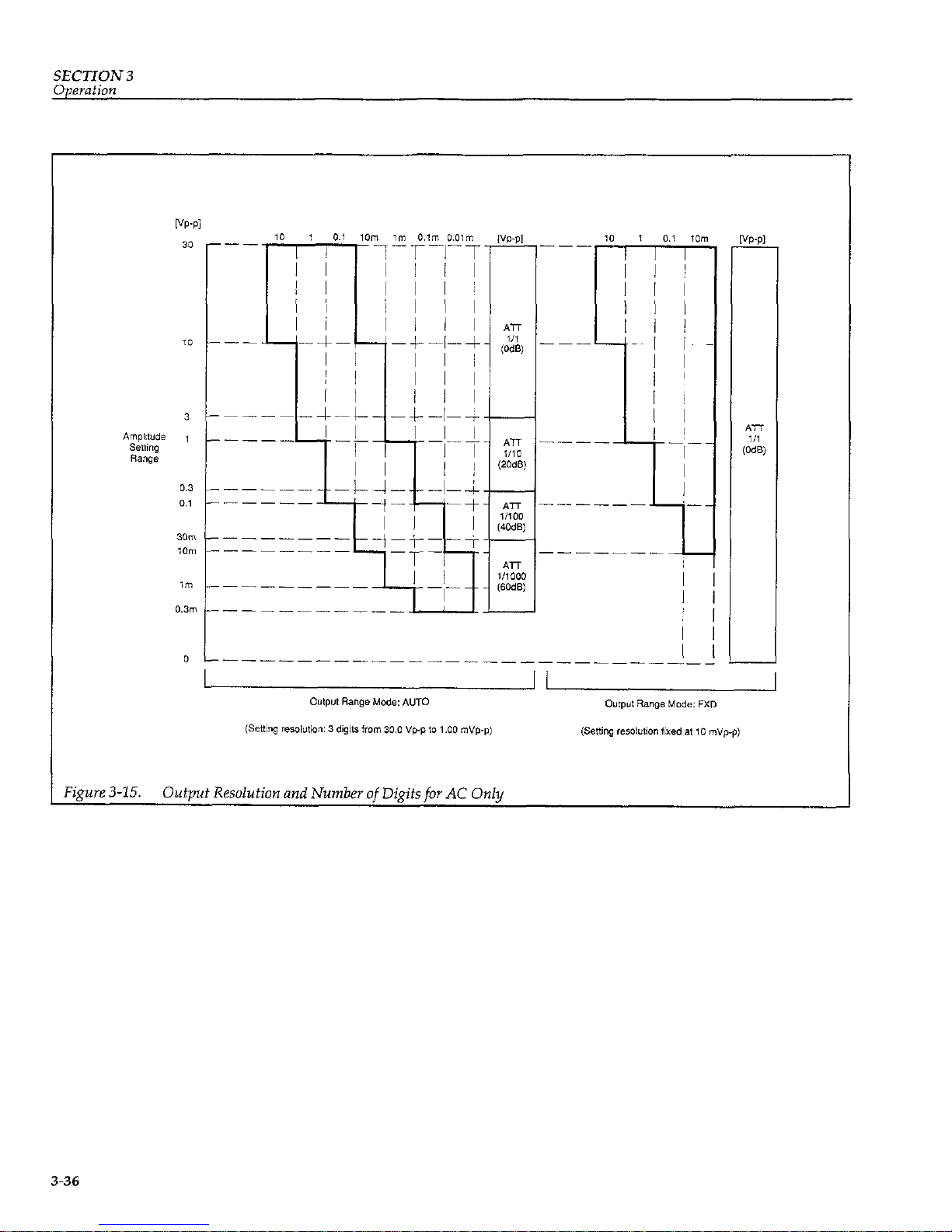
SECTION 3
Operation
Figure 3-15. Output Resolution and Number of Digits for AC Only
3-36
Page 56

SECTION 3
Operation
‘igure 3-16. Setting Resolution and Number of Digits for DC Only
3-37
Page 57

SECTION 4
GPIB OPERATION
4.1 INTRODUCTION
4.1 .l GPIB Overview
The GPIB interface is a general-purpose interface bus system recognized by the IEEE (Institute of Electrical and
Electronics Engineers) in 1975 and is a method of standardizing data transfer between measuring instruments
and peripherals. By building each controller and peripheral device into an interface conforming to this standard,
it is possible to establish complete hardware compatibility among devices.
Up to 15 devices may be connected to a single interface
bus, and data transfer is performed by three handshake
lines, enabling reliable data transfer between data send-
ers (talkers) and receivers (listeners) having differing
data transfer rates.
4.1.2 Major GPIB Specifications
Overall cable length: 20x1~ maximum
Cable lengths between devices: 4m maximum
Number of devices connectable
(including a controller): 15 maximum
Transfer method: 3-Line handshake
Transfer rate: 1M bytes/m (maximum)
Data transfer: S-bit parallel
Signal lines:
Data bus: 8 Lines
Control bus: 8 Lines
(including DAV, NRF’D, and NDAC handshake
lines and ATN, REN, IFC, SRQ, and EOI
control lines)
Signal/system grounds: 8 Lines
Signal logic: Negative
True (low-level): 0.8V maximum
False (high-level): 2.OV minimum
4-1
Page 58
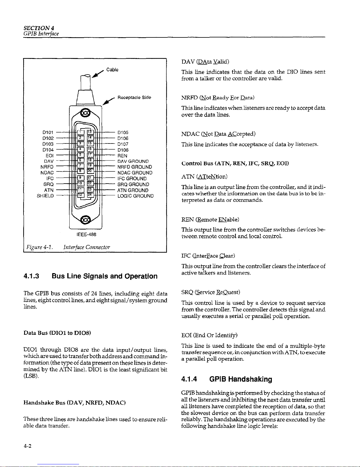
SECTION 4
GPIB
Interface
D101
D102
D103
D104
EOI
DA”
NRFD
NDAC
IFC
SRQ
ATN
SHIELD
D105
D106
D107
D108
REN
DAV GROUND
NRFD GROUND
NDACGROUND
IFC GROUND
SRQ GROUND
ATN GROUND
LOGIC GROUND
IEEE-488
‘igure 4-l.
InterfaceConnector
4.1.3 Bus Line Signals and Operation
The GPIB bus consists of 24 lines, including eight data
lines, eight control lines, and eight signal/system ground
lines.
Data Bus CD101 to DIOS)
DIOl through DIOS are the data input/output lines,
whichareusedtotransferbothaddressandcommandinformation (the type of data present on these lines is determined by the ATN line). DIOl is the least significant bit
(LSB).
Handshake Bus (DAV, NRFD, NDAC)
These three lines are handshake lines used to ensure reliable data transfer.
DAV (DAta Yalid)
This line indicates that the data on the DIO lines sent
from a talker or the controller are valid.
NRFD mot Ready For Data)
This line indicates when listeners are ready to accept data
over the data lines.
NDAC mot Data Xcepted)
This line indicates the acceptance of data by listeners.
cow01
BUS (ATN, REN, IFC, SRQ, EOI)
ATN (eTteNtion)
This line is an output line from the controller, and it indi-
cates whether the information on the data bus is to be ix-
terpreted as data or commands.
REN @emote ENable)
This output line from the controller switches devices be-
tween remote control and local control.
This output line from the controller clears the interface of
active talkers and listeners.
This control line is used by a device to request service
from the controller. The contmller detects this signal and
usually executes a serial or parallel poll operation.
EOI (End Or Identify)
This line is used to indicate the end of a multiple-byte
transfer sequence or, in conjunction with ATN, to execute
a parallel poll operation.
4.1.4
GPIB Handshaking
GI’IB handshaking is performed by checking the status of
all the listeners and inhibiting the next data transfer until
all listeners have completed the reception of data, so that
the slowest device on the bus can perform data transfer
reliably. The handshaking operations are executed by the
following handshake line logic levels:
4-2
Page 59
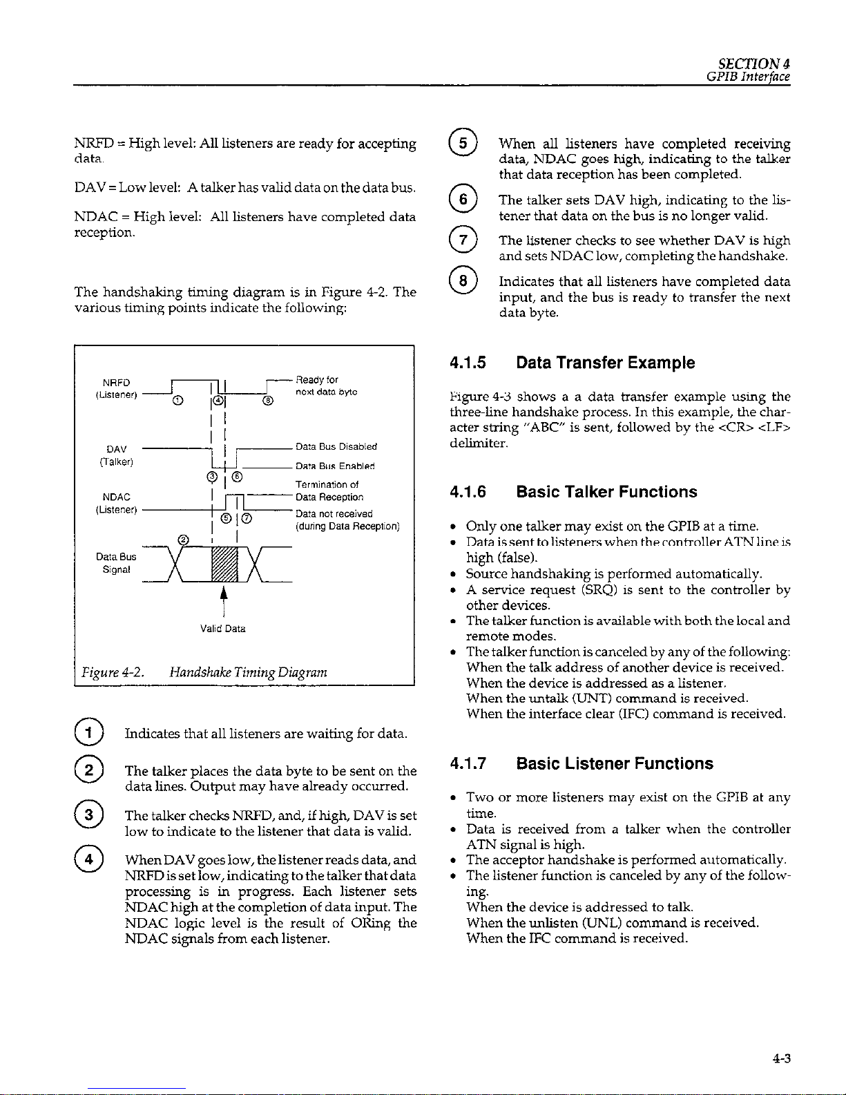
SECTION
4
GPIB Interface
NRJ’D = High level: All listeners are ready for accepting
data.
DAV = Low level: A talker has valid data on the data bus.
NDAC = High level: All listeners have completed data
W2C?pti0*.
The handshaking timing diagram is in Figure 4-2. The
various timing points indicate the following:
When all listeners have completed receiving
data, NDAC goes high, indicating to the talker
that data reception has been completed.
@
The talker sets DAV high, indicating to the listener that data on the bus is no longer valid.
0
The listener checks to see whether DAV is high
and sets NDAC low, completing the handshake.
Indicates that all listeners have completed data
input, and the bus is ready to transfer the next
data byte.
Valid Data
Figure 4-2. Handshake Timing Diagram
0
Indicates that all listeners are waiting for data.
The talker places the data byte to be sent on the
data lines. Output may have already occurred.
0
The talker checks NRFD, and, if high, DAV is set
low to indicate to the listener that data is valid.
When DAV goes low, the listener reads data, and
NRFD is set low, indicating to the talker that data
processing is in progr&s. Each listener sets
NDAC high at the completion of data input. The
NDAC logic level is the result of ORing the
NDAC signals from each listener.
4.1.5
Data Transfer Example
Figure4-3 shows a a data transfer example using the
three-line handshake process. In this example, the character string “ABC” is sent, followed by the <CR> <LF>
delimiter.
4.1.6 Basic Talker Functions
l Only one talker may exist on the GPIB at a time.
l Data is sent to listeners when the controller ATN line is
high (false).
l Source handshaking is performed automatically.
l A service request (SRQ) is sent to the controller by
other devices.
. The talker function is available with both the local and
remote modes.
l The talker function is canceled by any of the following:
When the talk address of another device is received.
When the device is addressed as a listener.
When the untalk (UNT) command is received.
When the interface clear (IFC) command is received.
4.1.7
Basic Listener Functions
l Two or more listeners may exist on the GI’IB at any
time.
l Data is received from a talker when the controller
ATN signal is high.
l The acceptor handshake is performed automatically.
l The listener function is canceled by any of the follow-
ing.
When the device is addressed to talk
When the unlisten (UNL) command is received
When the IFC commandis received
4-3
Page 60

SECTION 4
GPIB
Interface
?gure 4-3.
Data Transfer Example
4.1.8
Basic Controller Functions
l The controller sends single-line commands such as
IFC and REN.
. Only one controller can be active on the GPIB.
4.1.9
Multi-Line Interface Messages
l The controller sets the ATN signal to low to address
devices to listen and talk, and to transmit commands
A multi-line interface message is sent over the data lines
such as DCL.
with ATN set low. Table 4-l summarizes these messages.
4-4
Page 61

T
0
0
1
i
MSG
MSG
MSG
MSG
MSG
MSG
MSG
-
Page 62
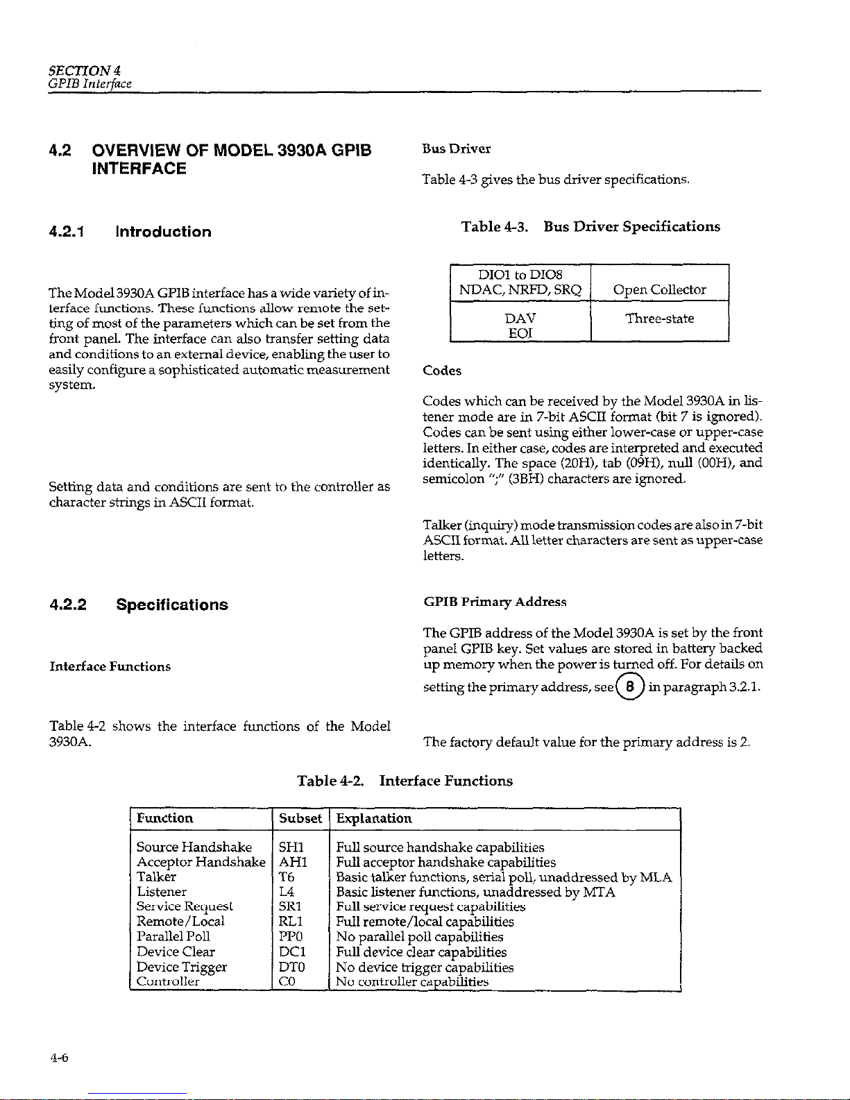
SECTION4
GPIB Interface
4.2 OVERVIEW OF MODEL 3930A GPIB
INTERFACE
4.2.1 Introduction
Bus Driver
Table 4-3 gives the bus driver specifications.
Table 4-3. Bus Driver Specifications
The Model 3930A GPIB interface has a wide variety of interface functions. These functions allow remote the setting of most of the parameters which can be set from the
front panel. The interface can also transfer setting data
and conditions to an external device, enabling the user to
easily configure a sophisticated automatic measurement
system.
Setting data and conditions are sent to the controller as
character strings in ASCII format.
4.2.2 Specifications
Interface Functions
Table4-2 shows the interface functions of the Model
3930A.
DAV
EOI
Three-state
Cd.3
Codes which can be received by the Model 3930A in lis-
tener mode are in 7-bit ASCII format (bit 7 is ignored).
Codes can be sent using either lower-case or upper-case
letters. In either case, codes are interpreted and executed
identically. The space (20H), tab (09H), null (OOH), and
semicolon “;” (3BH) characters are ignored.
Talker (inquiry) mode transmission codes are also in 7-bit
ASCII format. AU letter characters are sent as upper-case
ktteI3.
GPIB Primary Address
The GPIB address of the Model 3930A is set by the front
panel GPIB key. Set values are stored in battery backed
up memory when the power is turned off. For details on
setting the primary address, see
0.
8 m paragraph 3.2.1.
The factory default value for the primary address is 2.
Table 42. Interface Functions
Source Handshake
Explanation
Full source handshake capabilities
Full acceptor handshake capabilities
Basic talker functions, serial poll, unaddressed by MLA
Basic listener functions, unaddressed by MTA
Full service request capabilities
Full remote/local capabilities
No parallel poll capabilities
Full device clear capabilities
No device trigger capabilities
No contmller capabilities
4-6
Page 63
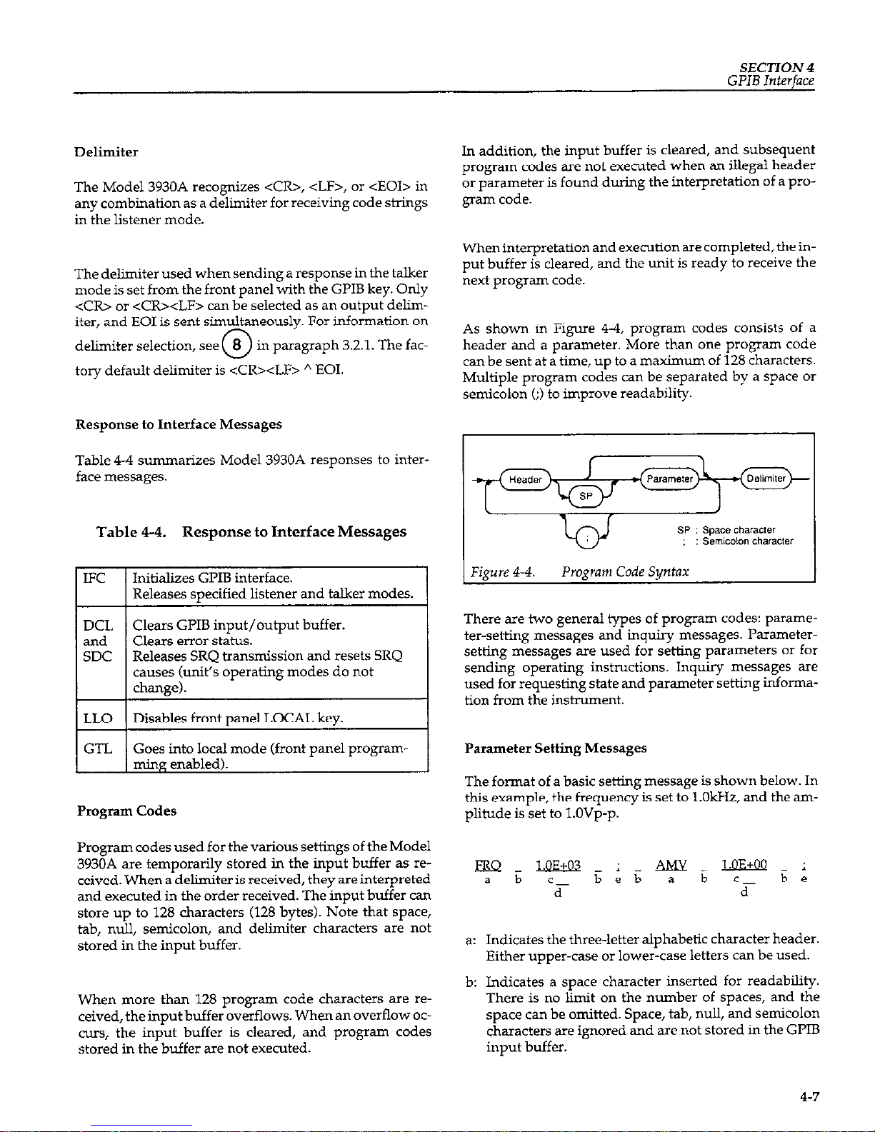
SECTION 4
GPIB Interface
Delimiter
The Model 3930A recognizes <CR>, <LF>, or <EOI> in
any combination as a delimiter for receiving code strings
in the listener mode.
The delimiter used when sending a response in the talker
mode is set from the front panel with the GPIB key. Only
<CR> or <CR><LF> can be selected as an output delimiter, and EOI is sent simultaneously. For information on
delimiter selection, see
0
8
in paragraph 3.2.1. The fac-
tory default delimiter is <CRxLF> h EOI.
Response to Interface Messages
Table 4-4 summarizes Model 3930A responses to interface messages.
Table 4-4. Response to Interface Messages
IFC
DCL
and
SDC
LLO
GTL
Initializes GPIB interface.
Releases specified listener and talker modes.
Clears GPIB input/output buffer.
Clears error status.
Releases SRQ transmission and resets SRQ
causes (unit’s operating modes do not
chance).
Disables front panel LOCAL key.
-I
Goes into local mode (front panel programming enabled).
Program Codes
Program codes used for the various settings of the Model
3930A are temporarily stored in the input buffer as received. When a delimiter is received, they are interpreted
and executed in the order received. The input buffer can
store up to 128 characters (128 bytes). Note that space,
tab, null, semicolon, and delimiter characters are not
stored in the input buffer.
When more than 128 program code characters are received, the input buffer overflows. When an overflow OC-
curs, the input buffer is cleared, and program codes
stored in the buffer are not executed.
In addition, the input buffer is cleared, and subsequent
program codes are not executed when an illegal header
or parameter is found during the interpretation of a program code.
When interpretation and execution are completed, the in-
put buffer is cleared, and the unit is ready to receive the
next program code.
As shown in Figure 44, program codes consists of a
header and a parameter. More than one program code
can be sent at a time, up to a maximum of 128 characters.
Multiple program codes can be separated by a space or
semicolon (;) to improve readability.
There are two general types of program codes: parameter-setting messages and inquiry messages. Parametersetting messages are used for setting parameters or for
sending operating instructions. Inquiry messages are
used for requesting state and parameter setting inforrna-
tion from the instrument.
Parameter Setting Messages
The format of a basic setting message is shown below. In
this example, the frequency is set to l.OHz, and the amplitude is set to l.OVp-p.
a: Indicates the three-letter alphabetic character header.
Either upper-case or lower-case letters can be used.
b: Indicates a space character inserted for readability.
There is no limit on the number of spaces, and the
space can be omitted. Space, tab, null, and semicolon
characters are ignored and are not stored in the GPIB
input buffer.
4-7
Page 64
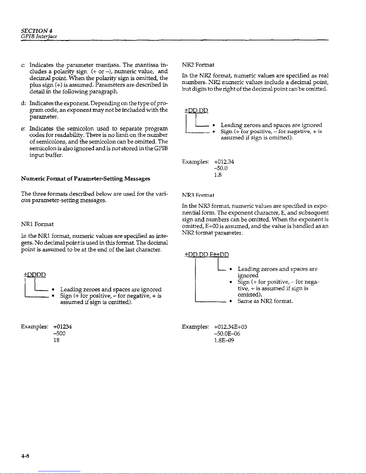
SECTION 4
GPIB Interface
C:
d:
e:
Indicates the parameter mantissa. The mantissa includes a polarity sign (+ or -), numeric value, and
decimal point. When the polarity sign is omitted, the
plus sign (+) is assumed. Parameters are described in
detail in the following paragraph.
Indicates the exponent. Depending on the type of program code, an exponent may not be included with the
parameter.
Indicates the semicolon used to separate program
codes for readability. There is no limit on the number
of semicolons, and the semicolon can be omitted. The
semicolon is also ignored and is not stored in the GPIB
input buffer.
Numeric Format of Parameter-Setting Messages
The three formats described below are used for the various parameter-setting messages.
NRl Format
In the NRl format, numeric values are specified as integers. No decimalpointis used in this format. The decimal
point is assumed to be at the end of the last character.
km
/
l Leading zeroes and spaces are ignored
l Sign (+ for positive, -for negative, + is
assumed if sign is omitted).
Examples: +01234
-500
18
NR2 Format
In the NR2 format, numeric values are specified as real
numbers. NR2 numeric values include a decimal point,
but digits to the right of thedecimalpoint canbe omitted.
fDD.DD
I I
L-
I.
Leading zeroes and spaces are ignored
l Sign (+ for positive, -for negative, + is
assumed if sign is omitted).
Examples: +012.34
-50.0
1.8
NR3 Format
In the NR3 format, numeric values are specified in expo-
nential form. The exponent character, E, and subsequent
sign and numbers can be omitted. When the exponent is
omitted, E+OO is assumed, and the value is handled as an
NR2 format parameter.
+DD.DD E&kDD
L
.
.
I.
Leading zeroes and spaces are
ignored
Sign (+ for positive, -for negative, + is assumed if sizn is
omitted).
Same as NR2 format.
Examples: +012.34E+03
-5O.OE-06
1.8E-09
4-8
Page 65
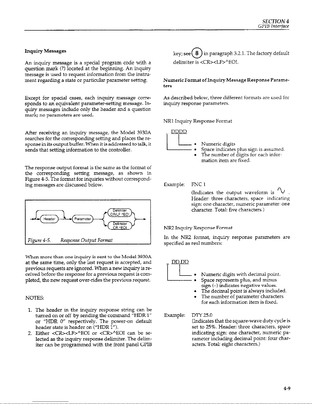
SECTION 4
GPIB Interface
Inquiry Messages
An inquiry message is a special program code with a
question mark (?) located at the beginning. An inquiry
message is used to request information from the instrument regarding a state or particular parameter setting.
Except for special cases, each inquiry message corresponds to an equivalent parameter-setting message. Inquiry messages include only the header and a question
mark; no parameters are used.
After receiving an inquiry message, the Model 3930A
searches for the corresponding setting and places the re-
sponse in its output buffer. When it is addressed to talk, it
sends that setting information to the controller.
The response output format is the same as the format of
the corresponding setting message, as shown in
Figure 4-5. The format for inquiries without corresponding messages are discussed below.
@we 4-5.
Response Output Fomt
When more than one inquiry is sent to the Model 3930A
at the same time, only the last request is accepted, and
previous requests are ignored. When a new inquiry is re-
ceived before the response for a previous request is com-
pleted, the new request over-rides the previous request.
NOTES:
1. The header in the inquiry response string can be
turned on or off by sending the command “HDR 1”
or “HDR 0” respectively. The power-on default
header state is header on (“HDR 1”).
2. Either <CR><LF>“EOI or <CW”EOI can be selected as the inquiry response delimiter. The d&riter can be progmmmed with the front panel GI’IB
key; see
0
8 in paragraph 3.2.1. The factory default
delimiter is <CR><LF>“EOI.
Numeric Format of Inquiry Message Response Parameters
As described below, three different formats are used for
inquiry response parameters.
NRl Inquiry Response Format
DDDD
-I I
Lk
Numeric digits
l Space indicates plus sign is assumed
. The number of digits for each infor-
mation item are fixed.
Example:
FNCI
(Indicates the output waveform is ‘L
Header: three characters, space indicating
sign: one character, numeric parameter: one
character. Total: five characters.)
NR2 Inquiry Response Format
In the NR2 format, inquiry response parameters are
specified as real numbers:
DD.DD
I I
k .
Numeric digits with decimal point.
. Space represents plus, and minus
sign (-) indicates negative values.
. The decimal point is always included.
. The number of parameter characters
for each information item is fixed.
Example: DTY 25.0
(Indicates that the square-wave duty cycle is
set to 25%. Header: three characters, space
indicating sign: one character, numeric parameter including decimal point: four characters. Total: eight characters.)
4-9
Page 66
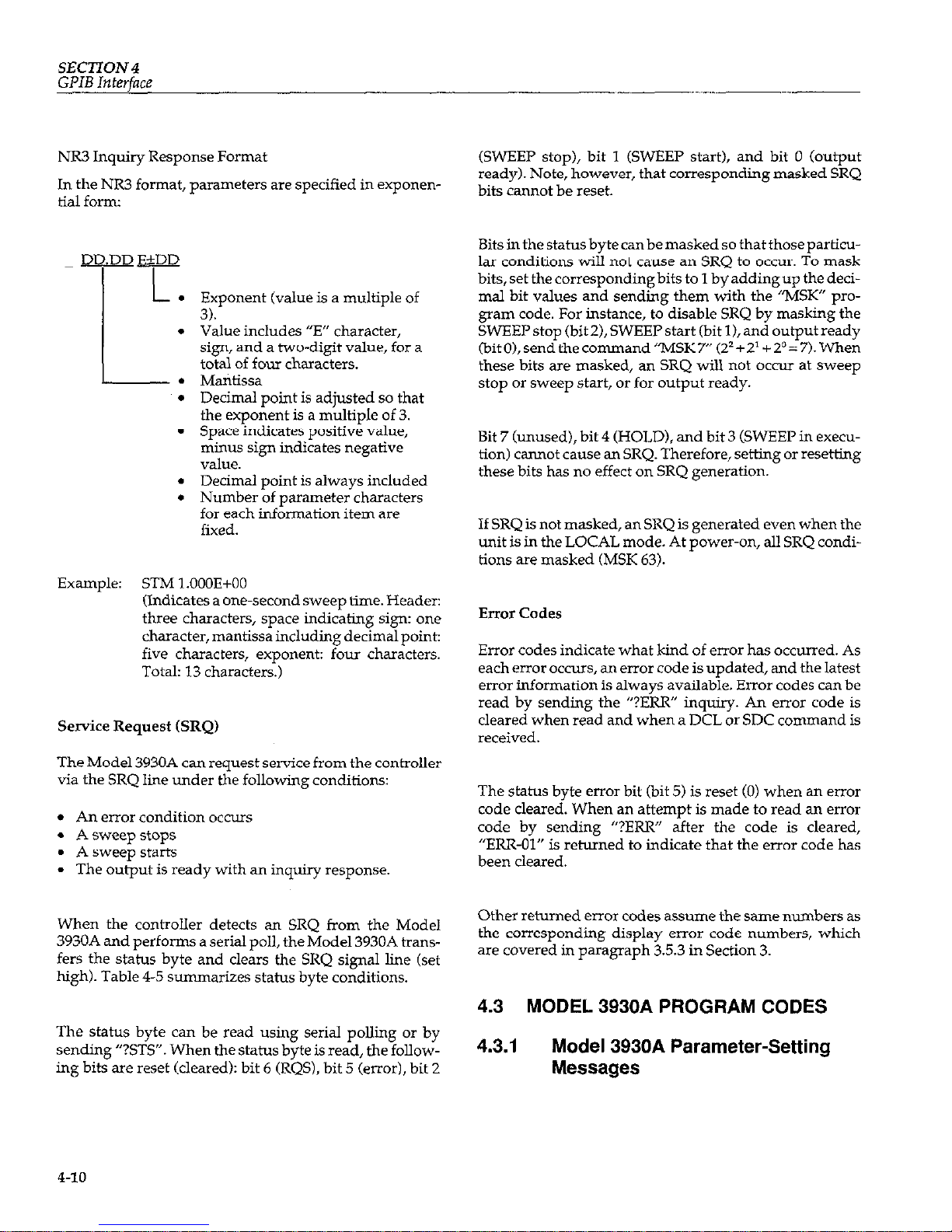
SECTION 4
GPIB
Interface
NR3 Inquiry Response Format
In the NR3 format, parameters are specified in exponen-
tial form
DD.DD E&DD
IL
.
I
.
L--.
.
.
.
.
Exponent (value is a multiple of
3).
Value includes “E” character,
sign, and a two-digit value, for a
total of four characters.
Mantissa
Decimal point is adjusted so that
the exponent is a multiple of 3.
Space indicates positive value,
minus sign indicates negative
value.
Decimal point is always included
Number of parameter characters
for each information item are
fixed.
Example: STM l.OOOE+OO
(Indicates a one-second sweep time. Header:
three characters, space indicating sign: one
character, mantissa including decimal point:
five characters, exponent: four characters.
Total: 13 characters.)
Service Request (SRQ)
The Model 3930A can request service from the controller
via the SRQ line under the following conditions:
l An error condition occurs
l A sweep stops
l A sweep starts
l The output is ready with an inquiry response.
When the controller detects an SRQ from the Model
3930A and performs a serial poll, the Model 3930A transfers the status byte and clears the SRQ signal line (set
high). Table 4-5 summarizes status byte conditions.
The status byte can be read using serial polling or by
sending “?STs”. When the status byte is read, the following bits are reset (cleared): bit 6 (RQS), bit 5 (error), bit 2
(SWEEP stop), bit 1 (SWEEP start), and bit 0 (output
ready). Note, however, that corresponding masked SRQ
bits cannot be reset.
Bits in the status byte canbe masked so that those particular conditions will not cause an SRQ to occur. To mask
bits, set the corresponding bits to 1 by adding up the deci-
mal bit values and sending them with the “MSK” program code. For instance, to disable SRQ by masking the
SWEEP stop (bit 2), SWEEP start (bit 11, and output ready
(bitO),send thecommand”MSK7” (22+21+20=7).When
these bits are masked, an SRQ will nol occur at sweep
stop or sweep start, or for output ready.
Bit 7 (unused), bit 4 (HOLD), and bit 3 (SWEEP in execution) cannot cause an SRQ. Therefore, setting or resetting
these bits has no effect on SRQ generation.
If SRQ is not masked, an SRQ is generated even when the
unit is in the LOCAL mode. At power-on, all SRQ conditions are masked (MSK 63).
Error Codes
Error codes indicate what kind of error has occurred. As
each error occurs, an error code is updated, and the latest
error information is always available. Error codes can be
read by sending the “?ERR” inquiry. An error code is
cleared when read and when a DCL or SDC command is
received.
The status byte error bit (bit 5) is reset (0) when an error
code cleared. When an attempt is made to read an error
code by sending “PERR” after the code is cleared,
“ERR-01” is returned to indicate that the error code has
been cleared.
Other returned error codes assume the same numbers as
the corresponding display error code numbers, which
are covered in paragmph 3.5.3 in Section 3.
4.3 MODEL 3930A PROGRAM CODES
4.3.1
Model 3930A Parameter-Setting
Messages
4-10
Page 67

SECTION 4
GPIB
Interface
Table 4-5. Status Byte
Bit 1 Descrintion
1 Set (1) Condition 1 Reset (0) Condition
(
:MSB)7 0
6
RQS
Always 0 (not used)
. When SRQ is issued.
Always 0 (not used)
l When status byte is sent.
l When DCL or SDC is received.
l When SRQ cause is cleared by
setting SRQ mask bits.
5
Error (SRQ cause)
l When an error occurs.
l When error code is requested
and sent using “?ERR”.
l When status byte is sent.
l When CCL or SIX is received.
4 HOLD l When sweep is interrupted due to l When sweep is restarted due to
sweep “HOLD”. “HOLD” release.
l When sweep is started during
“HOLD”.
l When sweep is hmwd off.
3 SWEEP in execution
. When sweep is started by sweep start.
. When sweep is halted due to the
l When sweep is restarted by releasing end of single sweep or sweep off.
“HOLD”. l When sweep is paused by
“HOLD”.
2 SWEEP stop
l When sweep is halted due to end of l When status byte is sent.
(SRQ cause)
single sweep or sweep off.
l When DCL or SDC is received.
. When sweep is stopped by “HOLD”.
1 SWEEP start
l When sweep is started by sweep start. l When status byte is sent
(SRQ cause) l When sweep is restarted by releasing
l When DCL or SDC is received
“HOLD”.
(LSB) 0 Output ready l When inquiry response data is ready l When status byte is sent.
(SRQ cause) for output.
l When talker is addressed.
l When next inquiry message is re-
ceived.
l When IXL or SK is received
4-11
Page 68

SECTION4
GPIB
Interface
Table 46.
Model 3930A Main Parameter Setting Messages
knction
WQUENCY
:EaOQ
WLITUDE
LPp-P
WLITUDE
Vms)
Only when output range
node is AUTO)
WLITUDE
dBV)
Only when output range
node is AUTO)
Program
Code
Header Parameter
Operation and Setting Range
Inquiry
l-Q
NR3 Sets oscillation frequency (frequency: Hz)
Yes
Range:
O.lE-03 (O.lmHz) to l.ZE+06
cw.Hz)
Resolution: O.lmHz
Example:
FRQ l.OE + 2 (IOOHz)
PRD
NR3 Sets oscillation frequency by period
Yes
(period: s)
Range:
0.84Eq6 (0.8 4~s = 1.19MHz)
to lO.OE+03 (10000s = O.lmHz)
Resolution: 0.01 )IS
Example:
PRD l.OE+OO Us = 1Hz)
AMV
NR3 Sets output amplitude Wp-p)
Yes
Range:
In AUTO output range mode:
0.3E-03 (03mVp-p) to
30.OE+OO (3OVp-p)
In FXD output range mode:
O.OOE+OO (OVp-p) to
30.00E+OO (3OVp-p)
Resolution:
In AUTO output range mode:
O.OlmVp-p
In FXD output range mode:
IOmVp-p
Example:
AMV 2.OE+OO (ZVp-p)
AMR
NR3
Sets output amplitude Wrms).
Yes
Range:
For sine wave:
O.llE4I3 (O.llmVrms) to
10.6E+OO (10.6Vrms)
For sawtooth or triangular:
0.09E-03 (0.09mVrms) to
8.66E+OO (8.66Vrms)
For square wave:
0.15EX13 (0.15mVrms) to
15.OE+OO (15.0Vrms)
Resolution: O.OlmVrms
Example:
AMR 7.1E+O (7.1Vrms)
AMD
NR3 Sets output amplitude (dBV).
YE
Range:
For sine wave:
-79.2E+OO (-79.2dBV) to
20.5E+OO (20.5dBV)
For sawtooth or triangular:
-80.9E+OO (-80.9dBV) to
lS.SE+OO (18.8dBV)
For square wave:
-76SE+OO (-76.5dBV) to
23.5E+OO (23.5dBV)
Resolution: O.ldBV
Example:
AMD-10.5E+O (-105dBV)
4-12
Page 69

SECTION 4
GPIB Interface
Model 3930A Main Synthesizer Parameter Setting Messages (Cont.)
OFS
FNC
Header
MOD
Code
Parameter
NR3
T
NRl
NRl
ODeration and Settine Ranee
Sets DC offset V
Range:
In AUTO output range mode:
-15.OE+OO (-15% to
15.OE+OO (15V)
In FXD output range:
-15.OE+OO (-15V) to
-15.OE+OO (15V)
Resolution:
In ALIT0 output rawe mode:
O.OlmV . In FXD output range mode:
1OmV
Examule:
OFS 4.56E-1 (0.456V)
Selects output wavefoim
Range: 0 to 5
0:
1:
5:
u
Example:
FNC 1 (sine wave)
Range: otoz
0:
CONT (continuous)
1: BRST (bust)
2: GATE
Example: MOD 0 (CONT)
4-13
Page 70

SECTION 4
GPIB Interface
Table 4-7. Model 3930A Trigger Parameter Setting Messages
junction
‘RIGGER SOURCE
Prop(ram Code
Header
Parameter Operation and Setting Range
Inqx
TRS
NRl Selects trigger source.
Yes
Range: 0 to 3
0:
Efl IL
1:
E-C-T 5
2:
3:
Es:
Example:
TRS 2 (triggered by1 of INT
Ye.3
TRIG GEN)
ZMOTE mGGER
TRG
NRl
Function equivalent to pressing front panel
Yes
MAN key. Valid only when trigger source is
EXT.
Bust:
Trigger occurs at changes from
TRG 0 to TRG 1.
Gate: Gate off with TRG 0 and gate
on with TRG 1.
Range:
0 or 1
0:
Trigger inactive (Same as
MAN key off)
1:
Trigger active (Same as MAN
key on)
Example:
TRG 1
IXT mG IN BNC
iNABLE
m NRl Selects whether or not front panel EXT
Yes
TRIG IN connector is enabled in remote
mode. (Enabled when trigger source is EXT
with TRE 1. Always enabled in local; when
the unit returns to remote, the status of the
previous remote mode is placed into effect.
Initial status at power up or when PST code
has been executed is TRE 1.)
Range:
0 or 1
0:
In remote mode, EXT TRIG IN
is disabled
1:
In remote mode, EXT TRIG IN
is enabled
Example:
TREl
NT TRIG GENERATOR
RIG MTE
TN7
NR3 Set internal trigger generator by period.
Range:
l.OEa6 (1~s) to 2.9999E+03
(2999.9s)
Resolution: 1 $s
Example:
TRR l.OE-3 (1x11s)
Yt!S
4-14
Page 71

SECTION4
GPIBInterface
Model 3930A Trigger Parameter Setting Messages (Cont.)
Function
[NT TRIG GENERATOR
mG FREQUENCY
Program Code
Header Parameter Operation and Setting Range Inquiry
TRF
NR3
Sets oscillation cycle of trigger generator by
Yes
frequency.
Range: 0.4Eq3 (0.4mHz = 2500s) to
LOE+06 mm2 = 1 pss)
Resolution: O.lmHz
Example:
TR!? 1.25E+03 (1.25kHz =
0.8md
BWJ COUNT
BST
jTART/STOP FHASE
SPH
NRl
NR2
Sets number of burst cycles.
Y‘S
Range:
lto65536
Example:
BST 10 (10 cycles)
Start/stop phase setting (“: degrees) Yes
Range: -360.0t0360.0 (-360"to360?
Resolution: 0.1”
Example:
SPH 180.0 (180”)
4-15
Page 72

SECTION 4
GPIB Interface
Table 4-8. Model 393OA Sweep Parameter Setting Messages
ERJZQUENCY
FREQUENCY
FREQUENCY
FREQUENCY O.lE-03 (O.lmHz) to
Resolution: O.lmHz
SNF l.OE+2 (100Hz)
SWEEPWJQ@R
FREQUENCY
SWEEP START PERIOD
SWEEP STOP PERIOQ
MKF
NR3
STD NR3
SPD NR3
Sets sweep marker frequency (frequency:
Yes
Hz).
Range:
O.lE-03 (0.lmI-W to
1.2E+O6 (1 .?.MHz)
Resolution: O.lmHz
Example: MKF l.OE+2 (100Hz)
Sets sweep start frequency by period Yes
(p+xizs).
Range:
0.86E-06 (0.86 ps = 1.19MHz)
to lO.OE+O3 (lOC4YJs = O.lmHz)
Resolution: 0.01 ps
Example: STD l.OOE+OO (1s = 1Hz)
Sets sweep stop frequency by period Y‘S
(period: s).
Range: 0.86E46 (0.86 ps = 1.19MJh)
to lO.OE+03 (l@OOOs = O.lmHz)
Resolution: 0.01~s
Example:
SPD l.OOE+OO (1s = 1Hz)
4-16
Page 73

SECTION 4
GPIB Interface
Main Synthesizer Sweep Parameter Setting Messages (Cont.)
Function
SWEEP CENT-ER PERIOD
Program Code
Header Parameter Operation and Setting Range Inquiry
CTD NR3 Sets sweep center frequency by period Yes
(period: s).
Range: 0.86Ea6 (0.86~~ = 1.19MIHz)
to lO.OE+03 (10000s = O.lmHz)
Resolution: 0.01~s
Example: CTD l.OOE+OO Us = 1Hz)
SWEEP SPAN- PERIOD SND NR3 Sets sweep span frequency by period Yes
(period: 5).
Range: 0.86E46 (0.861s = 1.19MIw
to lO.OE+03 (10000s = O.lmHz)
Resolution: 0.01~s
Example: SND l.OOE+OO (1s = 1Hz)
SWEEP -mR PERIOD
CENTER mOM MARKER
MKD NR.3 Sets sweep marker frequency by period
Yes
(period: s).
Range: 0.86E-06 (0.86 !~LS = 1.19MHz)
to lO.OE+03 (10000s = O.lmHz)
Resolution: O.O$s
Example: MKD l.OOE+OO (1s = 1Hz)
CFM
NOIW Assigns marker frequency to center fre-
NO
quency (assigns marker period to center period).
WEEP TW
SWEEP -~-Cl-ION
SWEEP OFF
SWEEP ~O~INUOIJS
START
SWEEP SINGLE START
STM
SFN
SOF
SCN
NR3
NRl
NOW
NOW2
Sets sweep time(s).
Range:
5.OEa3 (5ms) to 9.999E+03
(9999s)
Resolution: lms
Example: 5X-M l.OE+OO (1s)
Selects sweep function.
Range: oto4
0:
I
1:
Lin A
2: Lin A
3:
Log A
4:
Log u
Example:
SFN2(LEQl )
Disables sweep.
starts continuous sweep.
Yes
Yes
NO
NO
SSG
NOIW Starts single
sweep.
NO
4-17
Page 74
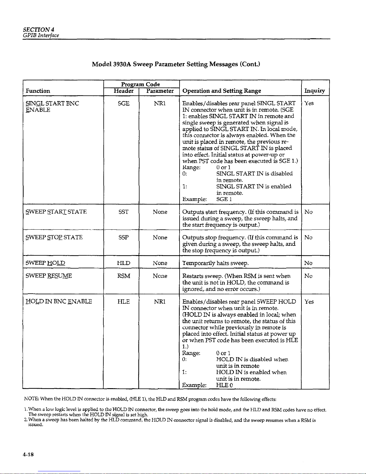
SECTION4
GPIB Interface
Model 3930A Sweep Parameter Setting Messages (Cont.)
?unction
applied to SINGL START IN. In local mode,
this connector is always enabled. When the
unit is placed in remote, the previous remote status of SlNGL START IN is placed
into effect. Initial status at power-up or
SINGL START IN is disabled
in remote.
ART IN is enabled
<WEEP &ESm
RSM
NOIE
Restarts sweep. (When RSM is sent when
the unit is not in HOLD, the command is
ignored, and no error occurs.)
No
3OIQ IN BNC ENABLE
HLE NRl Enables/disables rear panel SWEEP HOLD Yes
IN connector when unit is in remote.
(HOLD IN is always enabled in local; when
the unit returns to remote, the status of this
connector while previously in remote is
placed into effect. Initial status at power up
or when PST code has been executed is HLE
1.)
Range: 0 or 1
0: HOLD IN is disabled when
unit is in remote
1: HOLD IN is enabled when
unit is in remote.
Example: HLE 0
NOTE: When the HOLD IN connector is enabled, (FILE l), the HLD and RSM program codes have the following effects:
1. When a low logic level is applied to the HOLD IN comwctor, the sweep goes into the hold mode, and the HI.D and RSM codes have no effect.
The sweep restarts when the HOLD IN signal is set high.
2. When a sweep has been halted by the HLD command, the HOLD IN connector signal is disabled, and the sweep resumes when a RSM is
issued.
4-18
Page 75
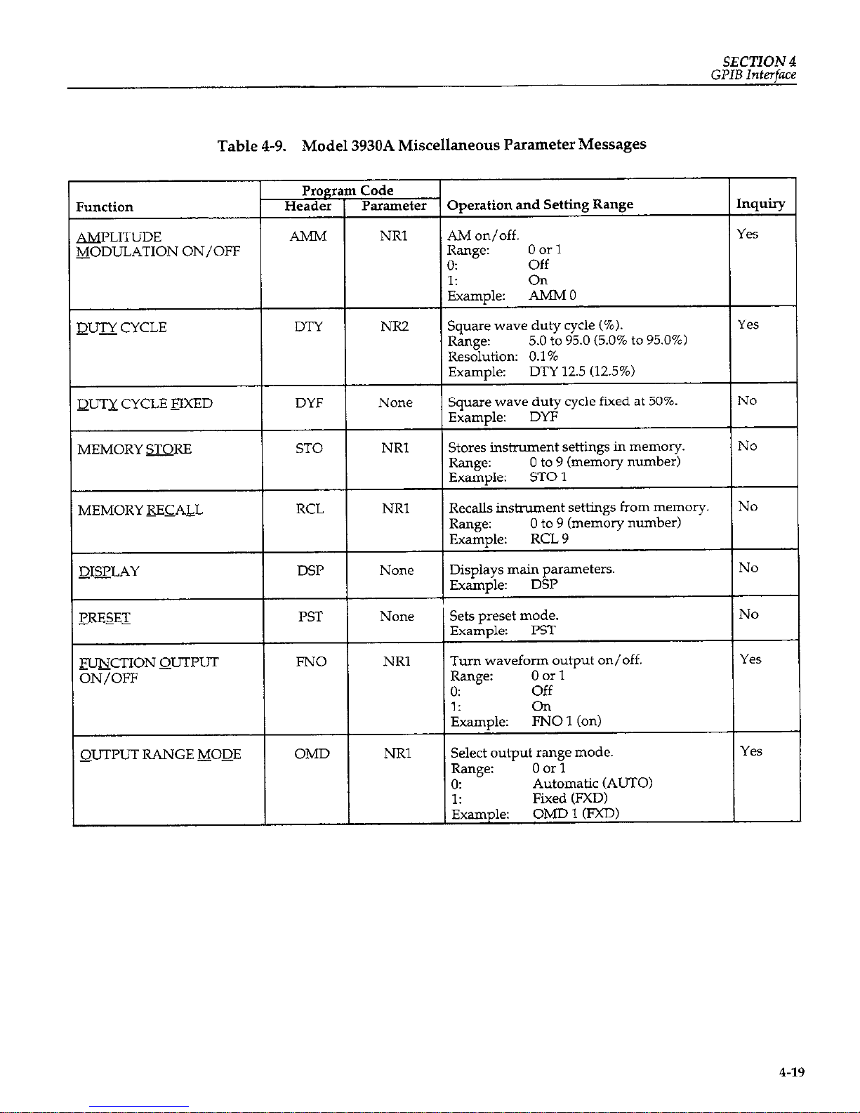
SECllON 4
GPIB Interface
Table 4-9. Model 3930A Miscellaneous Parameter Messages
&jODULATION ON/OFF
DTY 12.5 (12.5%)
MEMORY RECALL
-mmCTION QUTPUT
Turn waveform output on/off.
ON/OFF
QUTPUT RANGE MOQE
4-19
Page 76

SECTION 4
GPIB Interface
Table 4-10. Parameter Messages Specific to Model 3930A GPIB
Function
!5EAQEB ON/OFF
l-
Pr0g1
Header
HDR
I Code
Parameter
NRI
NR1
7
Operation and Setting Range
Selects on/off for header in inquiry response message.
Range: 0 or 1
0: No header in inquiry response
(off).
1: Include header in inauiry
response(on2 I ’
Exam&:
HDR 1 (on)
Sets SRQ mask bits.
Range:
00 to 63
32:
Error occurred.
32: No SRQ sent when error
0cc”rs.
0: Send SRQ when error
occurs.
16:
No effect. (same as 0.)
8:
No effect. (same as 0.)
4:
SWEEP stop.
4: No SRQ sent when
SWEEP stops.
0: Send SRQ when SWEEP
stops.
2:
SWEEP starts.
2: No SRQ sent when
SWEEP starts.
0: Send SRQ when SWEEP
starts.
1:
Output buffer ready with response to inquiry message.
1: No SRQ sent when output
buffer is ready.
0: Send SRQ when output
buffer is ready.
Add sum of above noted SRQ bits for multiple SRQ conditions.
Example:
MSK 6
(6 = 4 + 2: No SRQ sent at
SWEEP stop or SWEEP start.
SRQ sent with error and
output ready.)
[nquiry
Yes
Yes
4-20
Page 77
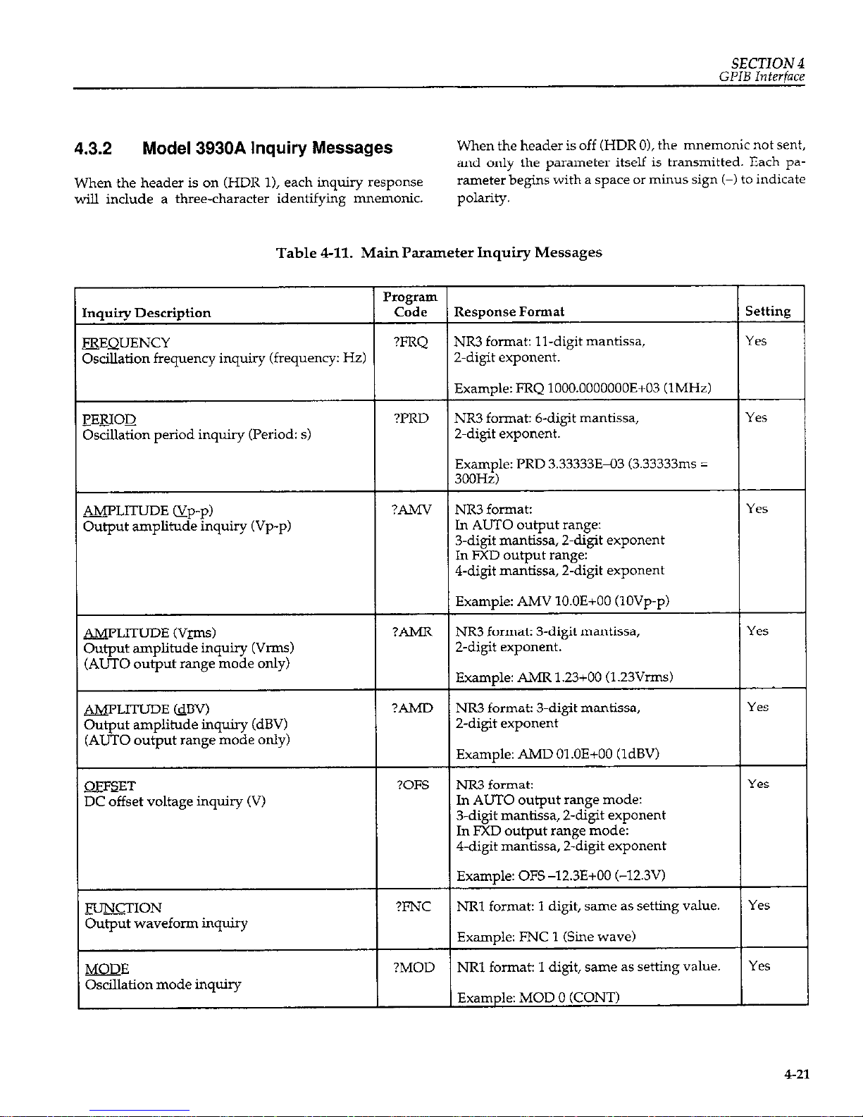
SECTION 4
GPIB
Interface
4.3.2
Model 3930A Inquiry Messages
When the header is on (HDR l), each inquiry response
will include a three-character identifying mnemonic.
When the header is off (HDR O), the mnemonic not sent,
and only the parameter itself is transmitted. Each parameter begins with a space or minus sign (-1 to indicate
phlity.
Table 4-11. Main Parameter Inquiry Messages
Program
Inquiry Description
Code Response Format
Setting
=EQUENCY
?FRQ
NR3 format: ll-digit mantissa, Yes
Oscillation frequency inquiry (frequency: Hz)
2.digit exponent.
Example: FRQ 1000.0000000E+03 (1MHz)
CEmOD
Oscillation period inquiry (Period: s)
?PRD
NR3 format: 6-digit mantissa, Yes
2.digit exponent.
Example: PRD 3.33333Ea3 (3.333331~ =
3OOHz)
AMPLITUDE ap-p,
Output amplitude inquiry (VP-p)
?AMV NR3 format:
Yes
In AUTO output range:
3.digit mantissa, 2.digit exponent
In IXD output range:
4-digit mantissa, Z-digit exponent
Example: AMV lO.OE+OO 0OVp-p)
&$I’LITUDE (Vms)
Output amplitude inquiry Wms)
(AUTO output range mode only)
?AMR
NR3 format: 3-digit mantissa, Yes
Z-digit exponent.
Example: Ah4R 1.23100 (1.23Vrms)
NLJTUDE UBV)
Output amplitude inquiry (dBV)
(AUTO output range mode only)
?AMD
NR3 format: 3-digit mantissa,
YE
2-digit exponent
Example: AMD Ol.OE+OO (1dBV)
QlFSET
DC offset voltage inquiry (V)
?OFS NRT? format:
In AUTO output range mode:
3-d@ mantissa, 2-digit exponent
In FXD output range mode:
Yes
4-d@ mantissa, 2-digit exponent
Example: OFS -12.3E+OO (-12.3V)
FuN_TION
Output wavefom inquiry
?FNC
NR1 format: 1 digit, same as setting value.
Yes
Example: FNC 1 (Sine wave)
l?l.QDE
Oscillation mode inquiry
?MOD
NRl format: 1 digit, same as setting value.
Yes
Example: MOD 0 (CONT)
Page 78
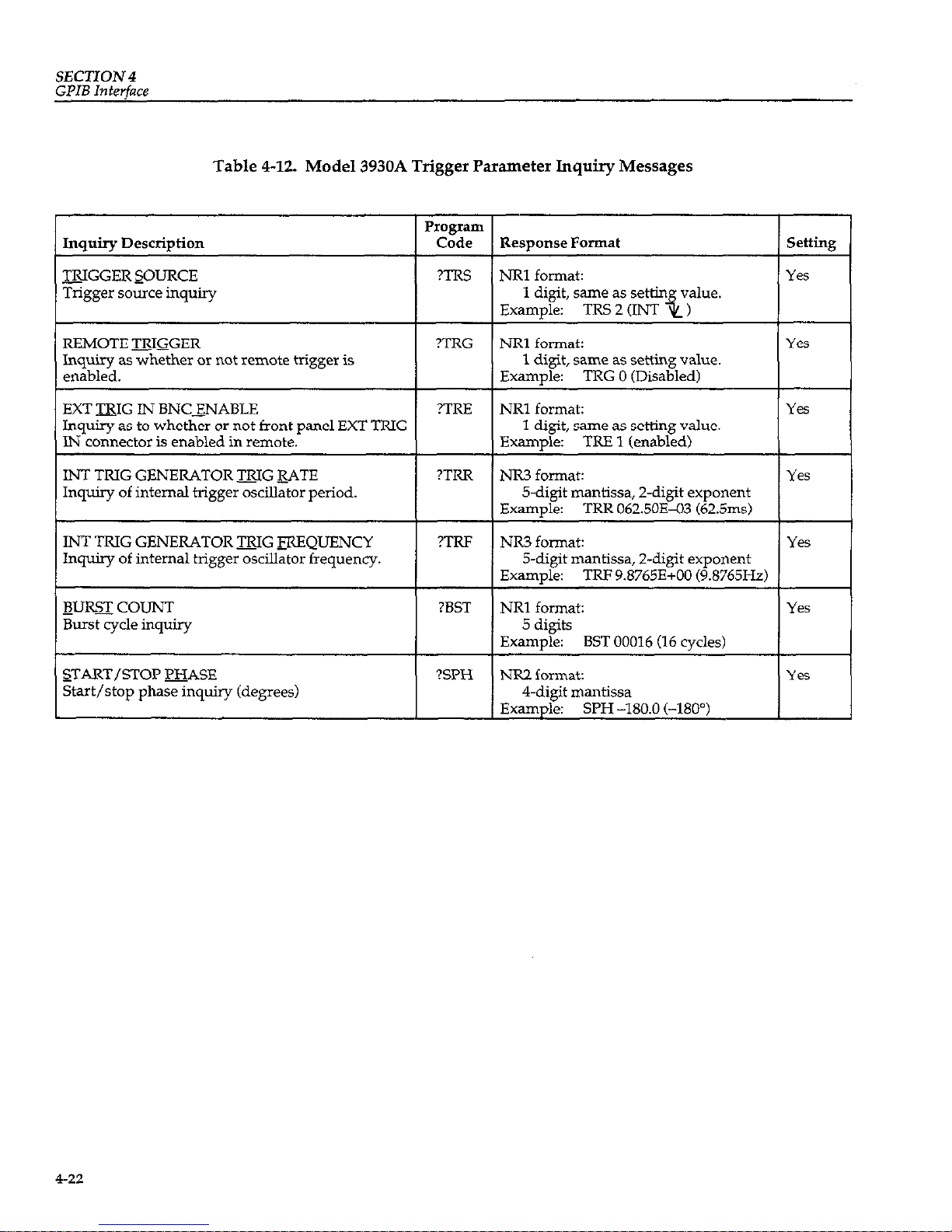
SECTION 4
GPIB
Interface
Table 4-12. Model 3930A Trigger Parameter Inquiry Messages
Inquiry Description
mGGER SOURCE
Trigger source inquiry
Program
Code
?TRS
Response Format
REMOTE mGGER
Inquiry as whether or not remote trigger is
enabled.
?TRG
NRl format:
1 digit, same as settin
value.
Example:
TRS 2 (INT
+i)
NRl formak
1 digit, same as setting value.
Examule:
TRG 0 (Disabled)
EXT WG IN BNCXNABLE ?TRE
NRl format:
Inquiry as to whether or not front panel EXT TRIG
1 digit, same as setting value.
IN connector is enabled in remote. Examule: TRE 1 (enabled)
INT TRIG GENERATOR BG &ATE
Inquiry of internal trigger oscillator period.
?TRR
NIX3 format:
5-d@ mantissa, 2-digit exponent
Example:
TRR 062.50Ea3 (62.5ms)
INT TRIG GENERATOR mG FREQUENCY
Inquiry of internal trigger oscillator frequency.
?TRF
NR3 format:
Yes
5-digit mantissa, Z-digit exponent
Exam&:
TRF 9.8765E+OO (9.8765H.z)
BIJlQJCOUNT
Burst cycle inquiry
?BST
NRl format:
5 digits
Examule:
BST 00016 (16 cvcles)
START/STOP BASE
Start/stop phase inquiry (degrees)
?SPH NR2 format:
4-digit mantissa
Example:
SPH -180.0 (-180”)
I Setting I
Yes
Yes
Yes
Yes
4-22
Page 79
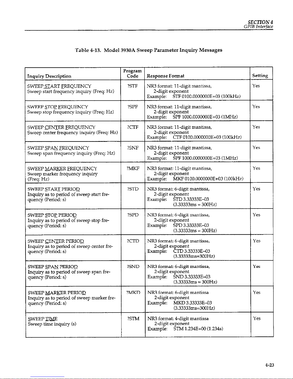
SECTION 4
GPIB
Interface
Table 4-13. Model 3930A Sweep Parameter Inquiry Messages
SWEEP CENTER FREQUENCY
Sweep center frequency inquiry (Freq: Hz)
SWEEP SPAN -mQUENCY
Sweep span frequency inquiry (Freq: Hz)
requency lnquny
od of sweep stop fre-
Inquiry as to period of sweep center fre-
quency (Period: s)
SWEEP sFAN_ PERIOD
Inquiry as to period of sweep span frequency (Period: s)
?SND
NR3 format: 6-digit mantissa,
Z-digit exponent
Example: SND 3.33333E-03
(3.33333ms = 300Hz)
SWEEP B-R PERIOD
Inquiry as to period of sweep marker frequency (Period: s)
?MKD NR3 format: 6-digit mantissa Yes
2-d@ exponent
Example: MKD 3.33333E-03
(3.33333ms=300Hz)
SWEEP TW
Sweep time inquiry (s)
?STM NR3 format: 4-digit mantissa Yes
Z-digit exponent
Example:
STh4 1.234E+OO (1.234s)
4-2.3
Page 80

SECTION 4
GPIB Interface
Model 3930A Sweep Parameter Inquiry Messages (Cont.)
Inquiry Description
&de
Response Format setting
I I I
WEEPJ3JKTION
I mw I
NRl format: 1 digit, same as setting value. Yes
Sweep function inquiry
Example: SFN 1
SlNGL START IN BNC ENABLE
Inquiry as to whether or not rear panel
SINGL START IN connector is enabled in
remote.
?SGE
NRI format: 1 digit, same as setting value.
Example: SGE 1 (enabled)
EOLD IN BNC ENABLE
Inquiry as to whether or not rear panel
SWEEP HOLD IN connector is enabled
while in remote.
?HLE
NRl format: 1 digit, same as setting value.
Example: HLE 0 (Disabled)
Yes
t
Yes
Table 4-14. Model 3930A Miscellaneous Parameter Inquiry Messages
I Inauiw Descriotion
I I
Program
Code
Response Format I Settim I
AMPLITUDE MODULATION
AM on/off inquiry
?AMM NRl format:
1 digit, same as setting value.
Exam&: AMM 1 (on)
Yes
Dm CYCLE
Square wave duty cycle inquiry (%)
?DTY NR2 format:
Yes
Z-digit mantissa
Example: DTY 25.0 (25%)
NOTE: If the duty cycle is 50% fixed, or if the
duty cycle is 50% variable, the response is DTY
50.0.
-W&KTION QUTPUT ON/OFF
Waveform output on/off inquiry
?FNO NRl format:
Yes
1 digit, same as setting value.
Example: FNO 1 (on)
QUTI’UT &ANGE MODE
Output range mode inquiry
?OMD NRl format:
1 digit, same as setting value.
Example: OMD 0 (AUTO)
4-24
Page 81
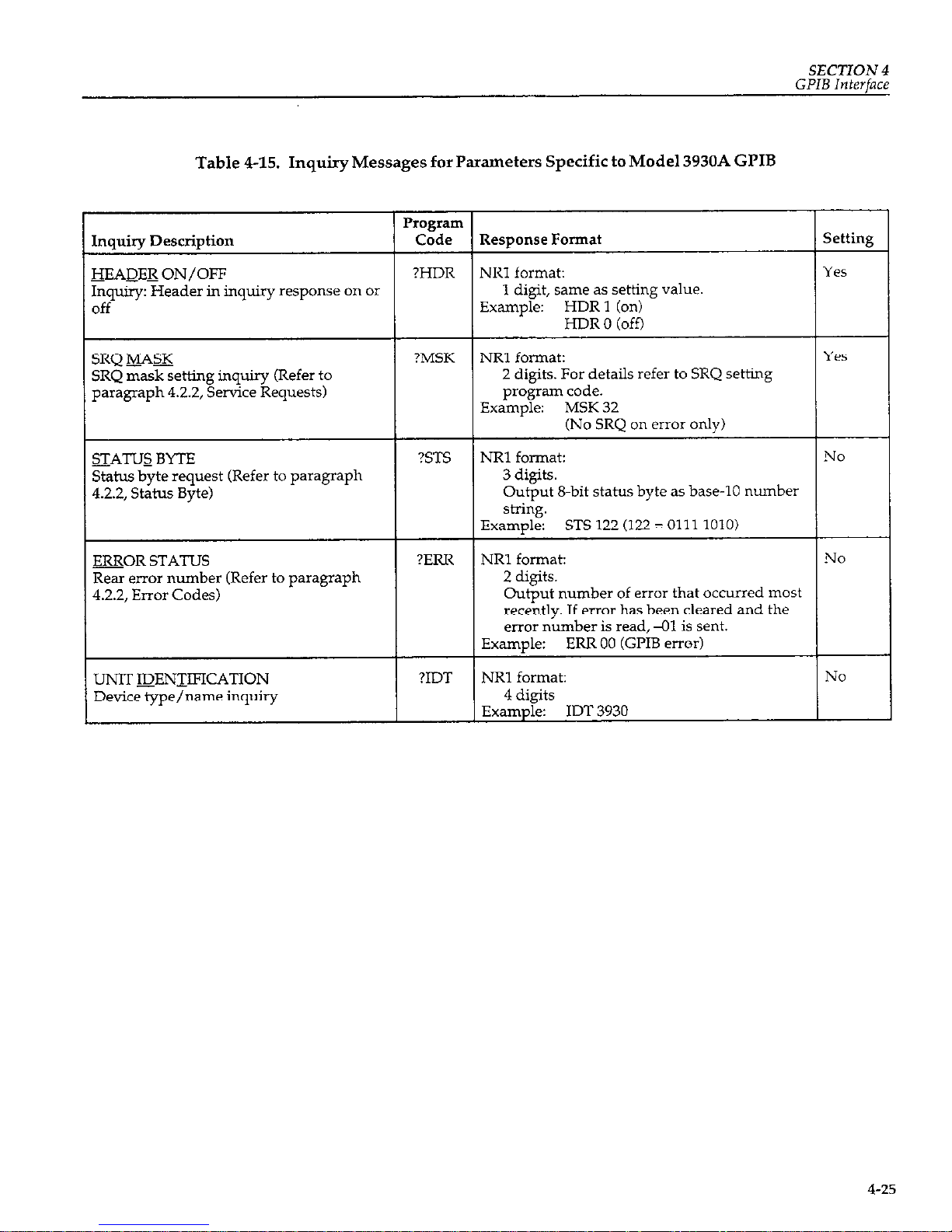
SECTION 4
GPIB Interface
Table 4-15. Inquiry Messages for Parameters Specific to Model 3930A GPIB
Program
Inquiry Description Code
Response Format setting
HEADEE ON/OFF ?HDR
NRl format: Yes
Inquiry: Header in inquiry response on or
1 digit, same as setting value.
off
Example: HDR 1 (on)
HDR 0 (ofi)
SRQ &&4%
SRQ mask setting inquiry (Refer to
paragraph 42.2, Service Requests)
?MSK
NRl format:
Yes
2 digits. For details refer to SRQ setting
program code.
Example: MSK 32
(No SRQ on error only)
STATUS BYTE
Status byte request (Refer to paragraph
4.2.2, Status Byte)
?STS
NRl format: No
3 digits.
Output 8.bit status byte as base-10 number
string.
Example:
STS 122 (122 = 0111 1010)
=OR STATUS
Rear error number (Refer to paragraph
4.2.2, Error Codes)
?ERR
NRl format: No
2 digits.
Output number of error that occurred most
recently. If error has been cleared and the
error number is read, 41 is sent.
Example:
ERR 00 (GI’IB error)
UNIT IDENTIFICATION
Device type/name inquiry
?IDT
NRl format: NO
4 digits
Example: IDT 3930
4-25
Page 82

SECTION4
GPIB
Interface
4.4 MODEL 3933A PHASE SHIFTER
Model 3933A, refer to the Model 3933A Instruction Man-
PROGRAM CODES
U?ll.
Program codes for the optional Model 3933A Phase Shif-
ter
are summarized in Table 4-16 through Table 4-23 for
your convenience. For detailed information on using the
4.4.1 Model 3933A Phase Shifter
Parameter Setting Messages
Table 4-16. Model 3933A Phase Shifter Main Parameter Setting Range
Function
PHASE
AMPLITUDE @p-p)
P&lPLJTUDE (V-rmss)
(AUTO output range mode
only)
Frog’
Header
PHS
AMV
AMR
Code
Parameter
NR2
NR3
NF.3
Operation and Setting Range
Phase difference between main signal from
Model 3930A and phase shifter output
(“: deg). -
Ranee: -360.0to 360.0
”
(-360.0°t0360.00)
Resolution: 0.1”
Example:
PHS 180.0 (180.0”)
Sets output amplitude Wp-p)
Range:
In AUTO output range mode:
0.3E-03 (0.3mVp-p) to
30.OE+OO (3OVp-p)
In FXD output range mode:
O.OOE+OO (OVp-p) to
30.00E+00 (3OVp-p)
Resolution: AUTO outnut range:
O.OlInVp-p FXD output range: IOmVp-p
Example:
AMV 2.OE+OO (2Vp-p)
Sets output amplitude (Vans)
Range: For sine wave:
O.llE-03 (O.llmVrms) to
10.6EtOO (10.6Vrms)
For sawtooth or triangular:
0.09E-03 (0.09mVrms) to
8.66E+OO (8.66Vrms)
For square wave:
0.15Eq3 (0.15mVrms) to
15.OE+OO (15.OVrms)
Resolution: O.OlmVrms
Example: AMR 7.1E+O (7.1Vn-n~)
Inquiry
Yes
YE
Yes
4-26
Page 83

SECTION4
GPIB
Interface
Model 3933A Phase Shifter Main Parameter Setting Range (Cont.)
bnction
MI’LITUDE @BV)
AUTO output range mode
W)
WXTION
AMD
OFS
I-WC
Program
Code
Header Pammeter
NIB
NR3
,
Operation and Setting Range
Ms output amplitude (dBV)
Range: For sine wave:
-792E+OO (-79.2dBV) to
20.5E+OO (20.5dBV)
For sawtooth or triangular:
-80.9EiOO (-80.9dBV) to
18.8EiOO WMdBV)
For same wave:
-76.56+00 (-76.5dBV) to
23.5E+OO (23.5dBV)
Resolution: O.ldBV
Examule: AMD -10.5E+O (-10.5dBV)
Sets DC offset voltage (V)
Range: In AUTO output range:
-15.OE+OO (-15V) to
15.OE+OO (15V)
In FXD output range:
-15.OE+OO (-15V) to
15.OE+OO (15V)
Resolution: AUTO output range: O.OlmV
FXD output range: 1OmV
Exam&: OFS 4.56E-1 (0.456V)
Selects output wavefom Selects output wavefom
Range: Range:
oto5 oto5
0: 0:
1: 1:
2: 2:
$ $
3: 3:
4: 4:
n” n”
5: 5:
Example: Example:
4-27
Page 84

SECTION 4
GPIB
Interface
Table 4-17. Model 3933A Phase Shifter Sweep Parameter Setting Messages
360.0to-360.0
360.0"to-360.0')
(360.0"to-360.0")
Resolution: 0.1”
Sets sweep span phase (“: deg)
000.0to-720.0
(000.0" to 720.0")
Resolution: 0.1”
SWEEP --ER PHASE
CENTER _FlIOM MARKER
WEEP T&fE
~WEEP-FUN_CTION
WEEP m
WEEP !ZOLYTINUOUS
START
CFM
STM
SFN
SOF
SCN
None
NR3
NRl
None
NOW?
Sets sweep marker phase (“: deg)
Range:
360.0to-360.0
(360.0"to-360.0")
Resolution: 0.1”
Example:
MKP 180.0 (180.0’)
Assigns
marker phase to center phase
Sets sweep time (s)
Range:
5.OE-03 (5ms) to 9.999E+03
(9999s)
Resolution: lms
Example:
STM l.OE+OO (1s)
Select sweep function
Range:
oto2
0:
1:
2:
5
Example:
SFN2(/l,
Disables sweep
Starts continuous sweep
NO
Yes
Yes
NO
NO
4-28
Page 85

SECTION 4
GJ’IB
Interface
Model 3933A Phase Shifter Sweep Parameter Setting Messages (Cont.)
‘unction
WEEI SINGLE START
‘INGL START BNC
:NABLE
Enables/disables rear panel SINGL START
IN BNC connector when unit is in remote.
(SGEl: when SINGL START IN is enabled,
and START signal is received, a single
sweep is performed. In local this connector
is always enabled. When unit is placed in
remote, status of SINGL START IN rehnns
Disables SINGL START IN
while unit is in remote.
Enables SINGL START IX
while unit is in remote.
;WEEP START STATE
iWEEP STOP STATE
iOLD IN BNC ENABLE
sweep not in HOLD,
the command
is ig-
nored and no error occurs.)
HOLD IN assumes the previous remote
status. Initial status at power up or when
the PST code has been executed is HLE 1.1
Disables HOLD IN when unit
is in remote.
Enables HOLD IN when unit
is in remote.
NOTE: men HOLD IN is enabled (HLE I), the relationship between the HOLD IN connector and the HLD and RSM codes is as f0110ws:
1. When a HOLD signal is applied to HOLD IN (set low), the HLD and RSM codes have no effect on the sweep. The weep restarts when
HOLD is removed from the HOLD W connector (set high).
2. When a sweep has been halted by the HLD code, the HOLD IN connector is disabled. The sweep resumes when a EM command is
issued.
4-29
Page 86

SECTION 4
GPIB
Interface
Table 4-18. Model 3933A Phase Shifter Miscellaneous Parameter Setting Messages
@ODULATION ON/OFF
QW- CYCLE
QUTY CYCLE FIXED
MEMORY STORE
MEMORY RECALL
1 QIZLAY
-FUN_CTION QIJTPUT
ON/OFF
I
QUTPUT PUNGE MODE
AMM NRl
DTY NR2
DYF
NOIW
+
ST0 NRl
PST None
EN0
NRl
OMD
NRl
Operation and Setting Range
AM on/off
Range: 0 or 1
0: Off
1: Oil
Example: AMM 0
Sets square wave duty cycle (%)
Range: 5.0 to 95.0 (5.0% to 95.0%)
Resolution: 0.1%
Example: DTY 12.5 (12.5%)
Sets square wave duty cycle to 50% fixed.
Example: DYF
Stores setting conditions in memory.
Range: 0 to 9 (memory number)
Example: ST0 1
Recalls setting conditions from memory
Range: 0 to 9 (memow number)
Ex&ple: RCL9 ,
Displays main parameters
Example:
DSP
Sets unit to preset settings
ExamDIe: PST
Turns waveform output on/off
Range: 0 or 1
0: Off
1: Oil
Example: FNO1
Selects output range mode
Range: 0 or 1
0: Automatic (AUTO)
1: Fixed (FXD)
Inquiry
Ye5
4-30
Page 87

SECTlON 4
GPIB
Interface
Table 4-19. Parameter Setting Messages Specific to Model 3933A Phase Shifter GPIB
unction
Program Code
Header Parameter
Operation and Setting Range Inquiry
tEADEE ON/OFF
HDR NRl
Enables/disables inquiry response message
Yes
header.
Range: 0 or 1
0:
No header in inquiry response
(off).
1: Include header in inquiry
response (on).
Example: HDR 1 (Header on)
RQ MASK
MSK NRl
Sets SRQ mask.
Y‘S
Range: 00 to 63
32:
Error occurred.
32:
No SRQ sent when error
OCCLXS.
0:
Send SRQ when error
occurs.
16: No effect &.me as 0)
8: No effect (same as 0)
4: SWEEP stop
4:
No SRQ sent when
SWEEP stops
0:
Send SRQ when SWEEP
stops
2: SWEEP start
2:
No SRQ sent when
SWEEP starts
0:
Send SRQ when SWEEP
starts
1: Output ready with inquiry
response message
1:
No output ready SRQ
0:
Send SRQ when output
ready with response.
Add up mask values for multiple SRQ con-
ditions.
Example: MSK 6
(6=4+2:NoSRQsentat
SWEEP stop or start. SRQ sent
at error generation and output
ready)
4-31
Page 88

SECTloN 4
GPIB Interface
4.4.2
Model 3933A Phase Shifter Inquiry
Messages
is off (HDR 01, the header is not send, and only the parameterisretumed.Theparameterbeginswithaspaceor
minus sign C-1.
The examples shown in Table 4-20 through Table 4-23
are for when the header is on (HDR 1). When the header
Table 4-20. Model 3933A Phase Shifter Main Parameter Inquiry Messages
Inauirv Descrivtion
I I
Program
Code Resuonse Format
Inquiry of phase difference between main
Model 3930A signal and Model 3933A out-
put
signal (“: den)
?PHS
NIX2 format: 6.digit mantissa
Example: PHS -180.0 (-180.0”)
AMPLITUDE @p-p,
Output amplitude inquiry (VP-p)
NR3 format:
In AUTO output range mode:
3-digit mantissa,
2-digit exponent
In FXD output range mode:
4-dipit mantissa.
2-d&t exponent
Example: AMV lO.OE+OO (lOVp-p)
&PLITUDE (Vms)
Output amplitude inquiry Wrms)
(AUTO output range mode only)
?AMR
NR3 format:
3.digit mantissa
Z-digit exponent
Example: AMR 1.23E+OO (1.23Vrms)
&WLITUDE UBV)
Output amplitude inquiry (dBV)
(ALJTO output range mode only)
?AMD NR3 format:
3-digit mantissa
Z-digit exponent
Example: AMD Ol.OE+OO (1dBV)
QESET
DC offset voltage inquiry
?OFS NR3 format:
In AUTO output range mode:
3-digit mantissa,
2-digit exponent
In FXD output range mode:
/I-digit mantissa,
Z-digit exponent
Examule: OFS -12.3E+OO (-12.3V)
-TION
Output waveform inquiry
?FNC NRl format:
1 digit, same as setting value.
Example: FNC 1 (sine wave)
setting
Yes
Ye.5
Yes
Yes
4-32
Page 89

SECTION 4
GPIB lnterfnce
Table 4-21.
Model 3933A Phase Shifter Sweep Parameter Inquiry Messages
Inquiry Description
3VEEP START WASE
$weep start phase inquiry (“: deg)
PIOgIaIIl
Code Response Format
?STP
NRZ format: 4-d@ mantissa
Example:
STP -120.0 (-120.0”)
SWEEP STOP PHASE
+eep stop phase inquiry co:, de&
SWEEP CEENTER PHASE
3veeu center uhase inauiw (“: dea)
?SPP
NR2 format: 4-digit mantissa
Example:
SPP -120.0 (-120’)
?CTP
NR2 format: 4-d@ mantissa
Example:
CTP 000.0 (0”)
SWEEP SPAN_ FHASE
Sweep phase span inquiry ?: deg)
SWEEP -&ARKER PHASE
Sweep marker phase inquiry (“: deg)
?SNP
NR2 format: 4-d@ mantissa
Example:
SNl’ 240.0 (240”)
?MKP
NR2 format: 4-digit mantissa
Example:
MKF 090.0 (90”)
SWEEP TW
Sweep tune inquiry W
?STM
I I
NR3 format: 4-d@ mantissa,
2-d@ exponent
Exam&:
STM 1.234E+OO U.234~)
SWEEP m7CTION
Sweep funchon inquiry
?SFN NRl format: 1 digit, same as setting value
Exampl,e: SFN 1
SINGL START IN BNC ENABLE
?SGE
Inq& as to whether or not rear panel
NRl format: 1 digit, same as setting value
Example: SGE 1 (enabled)
SINGL START IN BNC connector is enabled in remote
IJOLD IN BNC ENABLE
Inquiry as to whether or not rear panel
HOLD n\r connector is enabled in remote
?HLE
NRl format: 1 digit, same as setting value.
Example:
HL.E 0 (disabled)
setting
Yes
Table 422. Model 3933A Phase Shifter Miscellaneous Parameter Inquiry Messages
Inquiry Description
Program
Code Response Format
setting
&&$l’LlTUDE MODULATION
AM on/off inquiry
DUTY CYCLE
Square wave duty cycle inquiry (%)
?AMM NR2 format: 1 digit, same a setting value
Yes
Example:
AMM 1 (on)
?DTY
NR2 format: 2.digit mantissa
Yes
Example:
DTY 25.0 (25%)
NOTE: The reswnse is DTY 50.0 for both 50%
fixed and 50% hriable duty cyde.
1
I
-mCTION QUTI’UT ON/OFF
Waveform output on/off inquiry
QUTPU’I RANGE MODE
Output range mode inquiry
?FNO
NRl format: 1 digit, same as setting value
Yes
Example: FNO 1 (on)
?OMD
NRl format: 1 digit, same as setting value
Yes
Example:
OMD 0 (AUTO)
Page 90
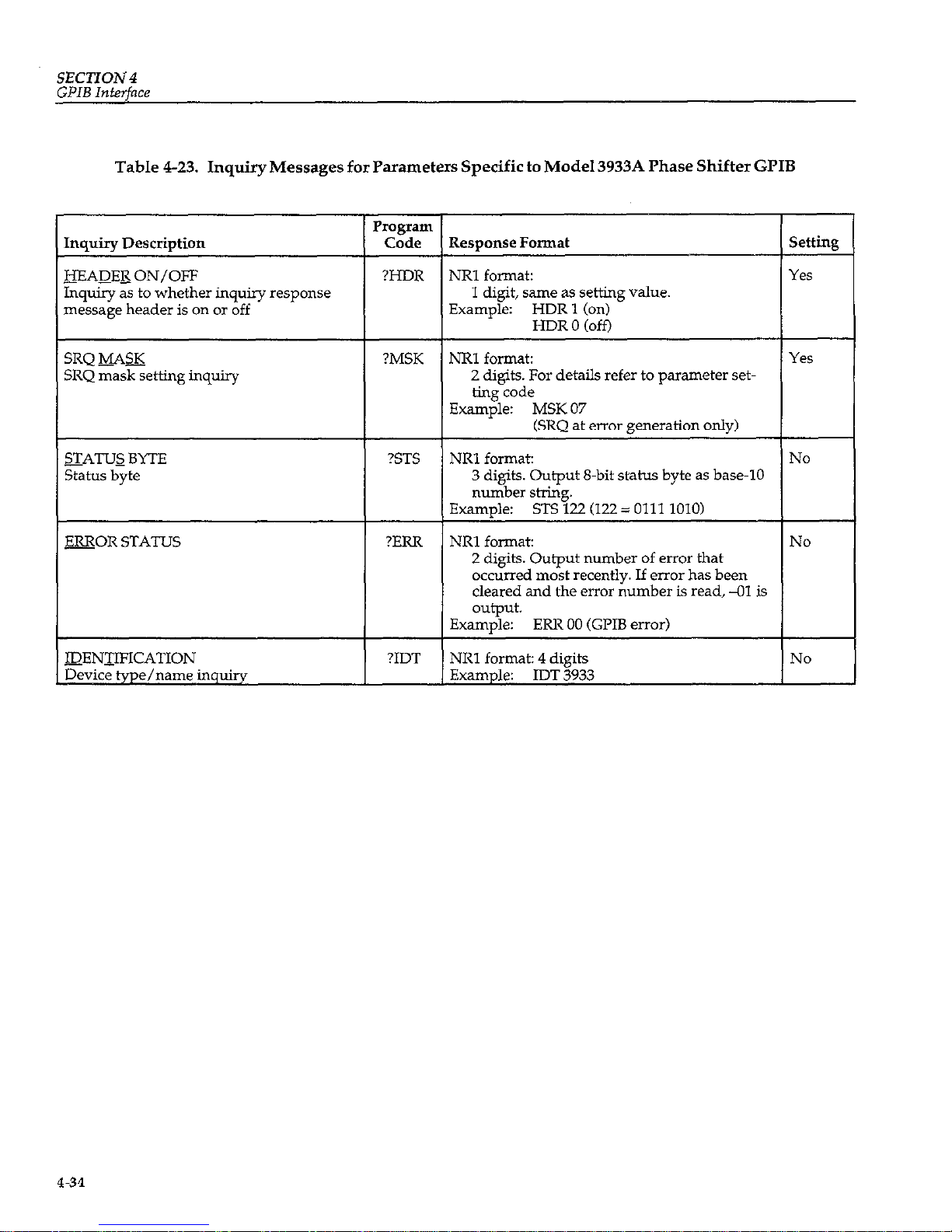
SECTION4
GPIB
Interface
Table 4-23. Inquiry Messages for Parameters Specific to Model 3933A Phase Shifter GPIB
Inquiry as to whether inquiry response
message header is on or off
1 digit, same as setting value.
Example: HDRl on
ut 8.bit status byte as base-10
number of error that
ecently. If error has been
e error number is read, -01 is
4-34
Page 91
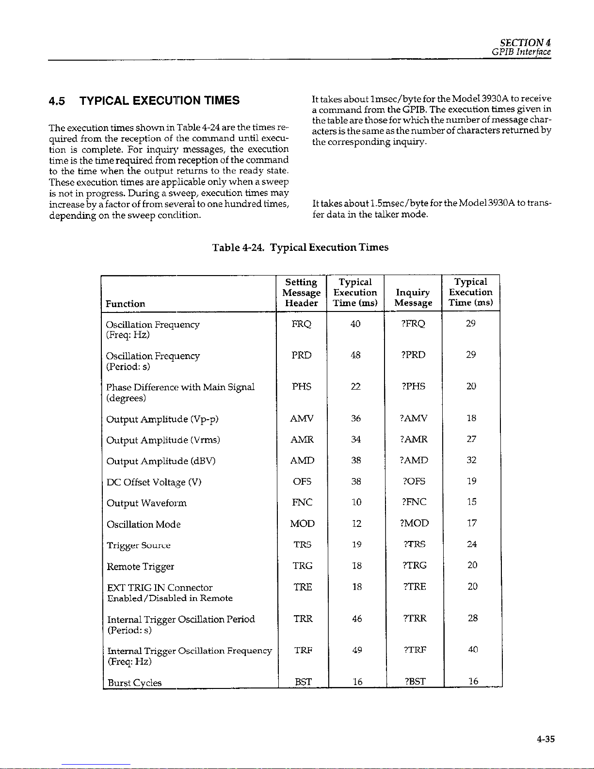
SECTION 4
GPIB
Interface
4.5 TYPICAL EXECUTION TIMES
It takes about lmsec/bytefor theMode 3930A to receive
a command from the GPIB. The execution times given in
The execution times shown in Table 4-24 are the times re-
quired from the reception of ihe command until execution is complete. For inqu* messages, the execution
time is the time required from reception of the command
to the time when the output returns to the ready state.
These execution times are applicable only when a sweep
is not in progress. During a sweep, execution times may
increase by a factor of from several to one hundred times,
depending on the sweep condition.
the table are those for which the number of message characters is the same as the number of characters returned by
the corresponding inquiry.
Ittakesabout 1.5msec/bytefor theModel3930A to transfer data in the talker mode.
Table 4-24. Typical Execution Times
Setting Typical Typical
Message Execution Inquiry Execution
Function Header
Time (ms)
Message Time (ms)
Oscillation Frequency
F=Q
40
?FRQ
29
(Freq: Hz)
Oscillation Frequency PRD
48
?PRD 29
(Period: s)
Phase Difference with Main Signal
PHS 22 ?PHS 20
(degrees)
Output Amplitude (VP-p) AMY 36 ?AMV 18
Gutput Amplitude Wrms) AMR 34 ?AMR 27
Output Amplitude (dBV) AhJD 38 ?AMD 32
DC Offset Voltage (V) OFS
38
?OFS 19
output Wavefo1n F-NC
10
?FNC
15
Oscillation M&e MOD 12
?MOD 17
Trigger Source TRS 19
?TRS
24
Remote Trigger TRG 18
?TRG 20
EXI’ TRIG IN Connector TRE 18 ?TRE 20
Enabled/Disabled in Remote
Internal Trigger Oscillation Period TRR
46
?TRR 28
(Period: s)
Internal Trigger Oscillation Frequency
TRF
49 ?TRF 40
(Freq: Hz)
Burst Cycles BST 16
?BST 16
4-35
Page 92

SECTION 4
GPIB
Interface
Typical Execution Times (Cont.)
Function
Start/stop Phase
Sweep Start Frequency
Sweep Stop Frequency
Sweep Center Frequency
Sweep Span Frequency
Sweep Marker Frequency
Sweep Start Frequency
Sweep Stop Frequency
Sweep Center Frequency
Sweep Span Period
Sweep Marker Period
Sweep Start Phase
Sweep Stop Phase
Sweep Center Phase
Sweep Phase Width
Sweep Marker Phase
Marker to Center Frequency
Marker to Center Phase
sweep Time
Sweep Function
sweep Off
start Continuous sweep
start Single Sweep
SINGL START IN
Connector Enabled/Disabled in
Remote
setting Typical
Typical
Message Execution Inquiry Execution
Header
Time (ms) Message Time (ms)
SPH 25 ?SPH
2.2
STF
56 ?STF 36
SFF 55 ?SPF
35
CTF 54 ?CTF
28
SNF 60 ?SNF
34
MKF 41 ?MKF
31
STD bb ?STD 32
SPD 71 ?SPD
31
CTD
73 ?CTD
36
SND 79
?SND 42
MKD 46 ?MKD
28
SW 36 ?STP
27
SFP 34
?SPP
25
CTP
32 ?CTP
16
SNP 41
?SNP
26
MKP 20
?MKF 19
CFM
56
-
CFM 23
-
STM
40 ?STM
25
SFN
14 ?SFN
19
SOF
(NC?E 1) -
SCN NOTE2
SSG
NOTE 2
SGE
14 ?SGE
16
436
Page 93
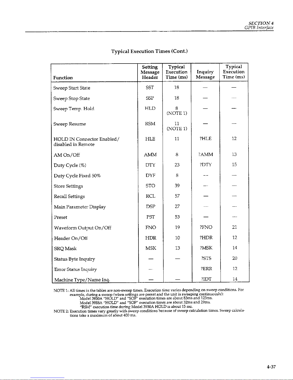
SECTION 4
GPIB
Interface
Typical Execution Times (Cont.)
Function
5weep start state
Sweep stop state
Sweep Temp. Hold
Sweep Resume
HOLD IN Connector Enabled/
disabled in Remote
AM On/Off
Duty Cycle (%)
Duty Cycle Fixed 50%
store settings
Recall Settings
Main Parameter: Display
Preset
Waveform Output On/Off
Header On/Off
SRQ Mask
Status Byte Inquiry
Error Status Inquiry
Machine Type/Name Inq.
setting
Typical
Typical
Message Execution
Inquiry
Execution
Header Time (ms)
Message
Time hs)
SST
18
SSP
18
HLD
(Not, 1)
RSM
(N:;E 1)
HLE
11
?HLE 12
AMM
8
?AMM 13
DTY 23
?DTY 15
DYF
8
ST0
39
RCL
57
DSP
27
PST
53
FNO
19
?FNO 21
HDR
10
?HDR
12
MSK 13
?MSK
14
?STS
20
-
?ERR
12
?IDT
14
4-37
Page 94
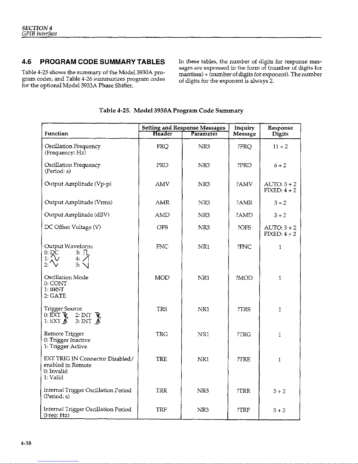
SECTION4
GPIB
Interface
4.6 PROGRAM CODE SUMMARY TABLES
Table 4-25 shows the summary of the Model 3930A program codes, and Table 4-26 summarizes program codes
for the optional Model 3933A Phase Shifter.
In these tables, the number of digits for response mes-
sages are expressed in the form of (number of digits for
mantissa) + (number of digits for exponent). The number
of digits for the exponent is always 2.
Table 4-25. Model 3930A Program Code Summary
Function
Oscillation Frequency
(Frequency: Hz)
Oscillation Frequency
(Period: s)
PRD
Output Amplitude (VP-p) AMV
Output Amplitude &‘I-&
Output Amplitude (dBV)
DC Offset Voltage (V)
output Wavefom:
;;“a
3: n
2%
4: /j
5: y
OsciUation Mode
3: CON-I
1: BRST
L: GATE
rrigger Source
,:EXTx LINT 2
1:EXTJi 3:INT ,J
Remote Trigger
I: Trigger Inactive
I: Trigger Active
SXT TRIG lN Connector Disabled/
mabled in Remote
I: Invalid
1: Valid
.nternal Trigger Oscillation Period
:Period: s)
.nternal Trigger Oscillation Period
‘Freq: Hz)
AMR
AMD
OFS
FNC
MOD
TRS
TRG
TRE
TRR
TRF
onse Messages
Parameter
;T
NR3
NR3
NR3
NR3
NR3
NR3
NRl
NRl
NRl
NRl
NRl
NR3
NR3
?FRQ
?PRD
?AMV
?AMR
?AMD
?OES
?FNC
?MOD
?TRS
?TRG
?TRE
?TRR
?TRF
Response
Digits
11+2
6+2
AUTO:3+2
FIXED: 4 + 2
3+2
3+2
AUTo:3+2
FJXED:4+2
1
1
1
1
1
5+2
5+2
4-38
Page 95
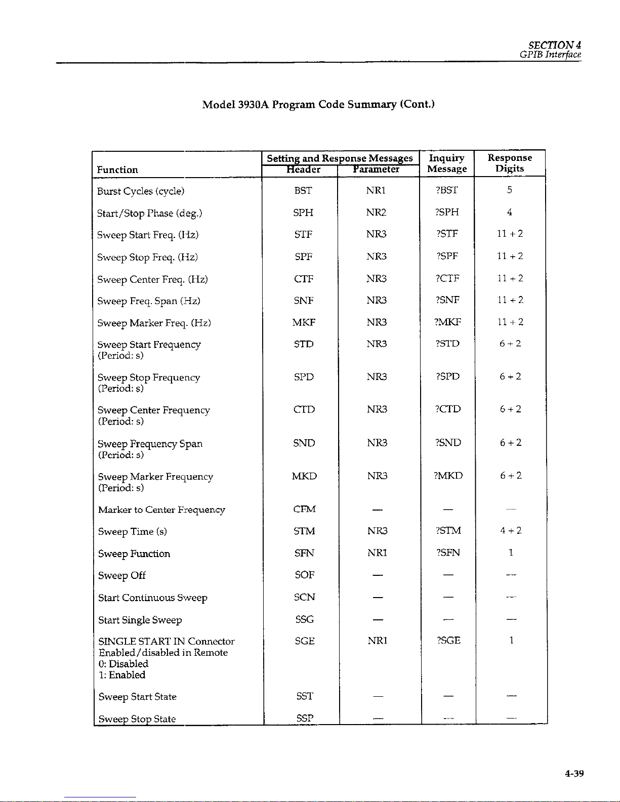
SECTION 4
GPIB Interface
Model 3930A Program Code Summary (Cont.)
?unction
3urst Cycles (cycle)
;tart/Stop Phase (deg.)
<weep Start Freq. (Hz)
%,wep Stop Freq. (Hz)
iweep Center Freq. (Hz)
;weep Freq. Span (Hz)
%.wp Marker Freq. (Hz)
jweep Start Frequency
Pskxlz s)
%veep Stop Frequency
&riod: s)
%eep Center Frequency
Period: s)
%.veep Frequency Span
(Period: s)
Sweep Marker Frequency
(Period: s)
Marker to Center Erequency
Sweep Time (s)
Sweep Function
Sweep Off
start Continuous Sweep
start Single sweep
SINGLE START IN Connector
Enabled/disabled in Remote
0: Disabled
1: Enabled
sweep start state
sweep stop state
ktting and Re
Header
BST
SPH
STF
SPF
CTF
SNF
MKF
STD
SPD
CTD
SND
MKD
CFM
STM
SFN
SOF
SCN
SSG
SGE
SST
SSP
mse Messages
parameter
NRI
NR2
NR3
NR3
NR3
NR3
NR3
NR3
NR3
NR3
NR3
NR3
NR3
NRl
NRl
Inquiry
Message
?BST
?SPH
?STF
?SPF
?CTF
?SNF
?MKF
?STD
Response
Digits
5
4
II+2
II+2
11 c2
~ll+z
~11+2
6+2
?SPD 612
?CTD
6+2
?SND
6+2
?MKD 6+2
?STM
4+2
?SFN 1
-
?SGE
-
1
-
4-39
Page 96

SECTION 4
GPIB Interface
Model 3930A Program Code Summary (Cont.)
Function
Sweep Hold
HOLD IN Connector Enabled/
disabled in Remote
0: Disabled
1: Enabled
AM On/Off
0: Off
1:On
Duty Cycle (%)
Duty Cycle Fixed 50%
store Settings
Recall Settings
Main Parameter Display
Preset Settings
Waveform output On/Off
Output Range Mode
Header On/Off
0: off
1: on
SRQ Mask
Status Byte Inquiry
Error Status Inquiry
Unit Type/Name Inquiry
HLD
RSM
HLE
AMM
DTY
DYF
ST0
RCL
DSP
PST
FNO
OMD
HDR
MSK
(ST3
(ERR)
(IDT)
-
-
NRl
NRl
NR2
-
NRl
NRl
-
-
NRl
NRl
NRl
NRl
(NRl)
(NRl)
(NRl)
Inquiry
MeSSage
-
-
?HLE
?AMM
?DTY
-
-
-
?FNO
?OMD
?HDR
?MSK
?STS
?ERR
?IDT
Response
Digits
1
1
3
-
-
1
1
1
2
3
2
4
4-40
Page 97

SECTION4
GPIB Interface
Table 4-26. Model 3933A Phase Shifter Program Code Summary
Function
Phase Difference with Main Signal
from Model 3930A (degrees)
Output Amplitude (VP-p)
Output Amplitude W-m)
Output Amplitude (dBV)
DC Offset Voltage (V)
output Waveform:
@DC
1: 2/
3:n
2:2/
4:/l
5: y
Sweep Start Phase (de&
Sweep Stop Phase (de@
Sweep Center Phase (de@
Sweep Phase Span (deg)
Sweep Marker Phase (de&
Marker to Center Phase
Sweep Time (5)
Sweep Function
0: J
1: A
2:A
Sweep Off
Start Continuous Sweep
start Single sweep
SINGL START IN Connector
Enabled/disabled in Remote
0: Disabled
1: Enabled
sweep start state
sweep stop state
S
L
PHS
AMV
AMR
AMD
OFS
FNC
STP
SPP
CTP
SNP
MKF
CFM
STh4
SFN
SOF
SCN
SSG
SGE
SST
SW
NR3
NR3
NR2
NR3
NRl
NR.?
NR3
NR3
NR3
NR3
NR.3
NRl
NRl
i
Inquiry
Message
?PHS
?AMV
?AMR
?AMD
?OFS
?FNC
?STP
?SPP
?CTP
?SNP
?MKP
?STM
?SFN
-
?SGE
Response
Digits
4
4UTO:3+2
‘IXED:4+2
3+2
3 + 2
4UTO:3+2
?IXED:4+2
1
4
4
4
4
4
4+2
1
-
1
4-41
Page 98

SECTION 4
GPIB Interface
Model 3933A Phase Shifter Program Code Summary (Cont.)
Function
Sweep Hold
Sweep Restart
HOLD IN Connector Enabled/
disabled in Remote
0: Disabled
1: Enabled
AM On/Off
0: Off
1: On
Duty Cycle (%I
Duty Cycle Fixed 50%
store settings
Recall Settings
Main Parameter Display
Preset settings
Waveform output On/Off
Output Range Mode
Header On/Off
0: Off
1: On
SRQ Mask
Status Byte Inquiry
Error Status Inquiry
Unit Type/Name
NOTE C I= Inquiry oniy.
HLD
RSM
HLE
AMM
DTY
DYF
ST0
RCL
DSP
PST
FNO
OMD
HDR
MSK
(ST3
(ERR)
(ID-0
-
NRl
NR2
-
NRl
NRl
-
NRl
NRl
NRl
NRl
(NRl)
(NRl)
(NRl)
Inquiry
Message
-
?HI.E
?AMM
?DTY
-
-
?FNO
?OMD
?HDR
?MSK
?STS
?ERR
?IDT
Response
Digits
-
1
1
3
-
1
1
1
2
3
2
4
4-42
Page 99

SECTION 4
GPIB Interface
4.7 SAMPLE PROGRfAMS
This paragraph presents two sample programs to control
the Model 3930A using an HIP 9816 (or equivalent) personal computer as the controiler. The primary address of
the Model 3930A GPIB interface is assumed to be 2, and
the delimiter is <CR><LF>.
Sample program 1 allows you to type in program codes
and send them to the Model 3930A. When the program
code begins with a “?“, the Model 3930A is addressed to
talk after the program code is transferred. The response is
then read by the controller and displayed on the CRT.
When an error occurs, a serial poll is performed, the error
code is read, and an error message is displayed on the
CRT.
Sample program 2 includes :subroutines for sending in-
terface messages IFC, DCL, :SDC, LLO, and GTL to the
Model 3930A and the subroutines to set REN true or
false.
Sample Program 1
100 PRIVTER IS I
110 DIM
C%[BOl
120 ON TlHEOlT 7.20 COSljB 690
130 ABORT 7
140 CLEAR 7
150 REMOTE 702
160 OUTPUT 702:"HSK 3,"
170 ON INTR 7 COT0 280
180 !
190 ENABLE INTR 7:2
200 INPUT "INPUT PROGRAM CODE".C$
210 PRINT
220 PRINT -COHHAND - ",C$
230 OLlTPUT 702:C%
240 IF POS(C$.'?') THEN CO:jUB 720
250
FOR I-O TO 500
260
lvEXT I
270 COT0 190
280 !
290 PRINT "tt: ERROR SERVICE ROUTINE W
300 S-SPOLL(702)
310 OUTPUT 702;"?ERR-
320
ENTEK 702:E%
330 OUTPUT 702:"?HDR"
340 ENTER 702:H$
350 IF HS-"HDR I" THEN
360 E-VhL(E$C4.61)
370
ELSE
380
E-VhL(E$)
390 E';D IF
400 SELECT E
410
CASE 0
420
PKINT ~ (ERROR 00) CPIB I:KKOR I-
430
CASE I
440
PRI\IT ~ (ERROR 01) LIT ERROR !~
450
CASE 2
460
PRIUT " (ERROR 02) FREQ ERROR !-
470
CASE 3
480
PRlhT ~ (CKRUK 03) WAS ,:KK"K !~
4YO CASE 4
500
PRINT " (ERROR 04) AHPT ERROR !~
510 CASE 5
520
PRINT ~ (ERROR 05) OFST ERROR !~
530 CASE 6
540
PRINT ~ (ERROR 06) ACDC ERROR !~
550 CASE 7
560
PRINT ~ (CKKOK 07) t'KDT ERRIlK !-
570
CASE 8
580
PRINT " (ERROR 08) SirP ERROR !590 CASE 9
GO0
PRINT ~ (ERROR 09) RICE ERROR !610 CASE IQ
620
PKI\T ~ (EKKOK 10) CNVT EKKUK I630 CASE II
640
PRIST ~ (ERROR II) MEMO ERROR !-
650
CASE 12
ti60
PRI\T ~ (I:RKOR 12) \;ODT IEHROR !670 EKD SELECT
680 GOT0 190
690 !
700
PRINT "tt CPIB Hans UP tt-
710
RETURLI
720 !
730
ENTER 702:C$
740 PRINT ~ ANSYER - ".C$
750 RETURN
160 !
770
END
4-43
Page 100
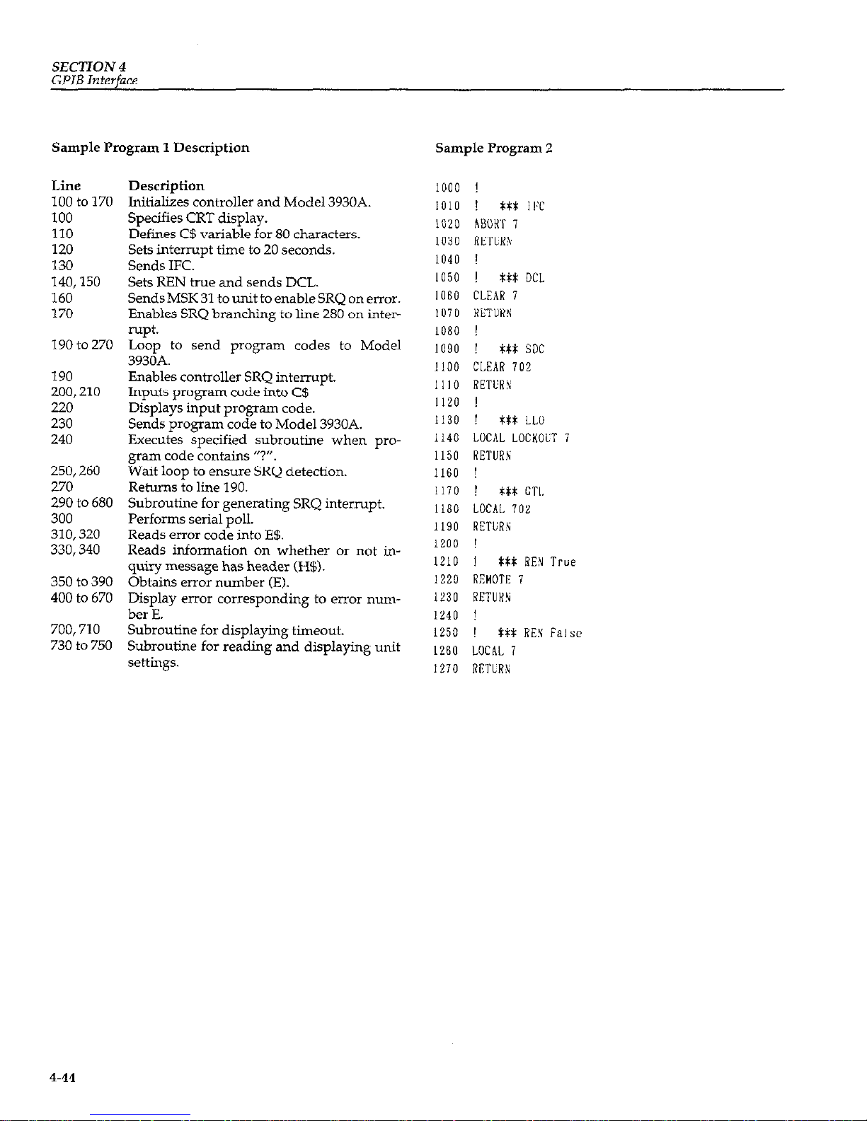
SECTION 4
GPIB Interface
Sample Program 1 Description Sample Program 2
Line
100to170
100
110
120
130
140,150
160
170
190to270
190
200,210
220
230
240
250,260
270
290to680
300
310,320
330,340
350to390
400to670
700,710
730to750
Description
Initializes controller and Model 3930A.
Specifies CRT display.
Defines C$ variable for 80 characters.
Sets interrupt time to 20 seconds.
Sends IFC.
Sets REN true and sends DCL.
Sends MSK 31 to unit to enable SRQ on error.
Enables SRQ branching to line 280 on interrupt.
Loop to send program codes to Model
3930A.
Enables controller SRQ interrupt.
Inputs program code into C$
Displays input program code.
Sends program code to Model 3930A.
Executes specified subroutine when program code contains ‘?“.
Wait loop to ensure SRQ detection.
Returns to line 190.
Subroutine for generating SRQ interrupt.
Performs serial poll.
Reads error code into E$.
Reads information on whether or not in-
quiry message has header (H$).
Obtains error number (E).
Display error corresponding to error nunber E.
Subroutine for displaying timeout.
Subroutine for reading and displaying unit
settings.
1000 !
1010 !
it* I IT
1020 ABOH 1
I030 RETL;R\
1040 !
1050 !
t*t DC1
1060 CLEAR 7
lU7D
RETURN
1080 !
1090 !
Ml: SDC
1100 CLEAR 702
1110 RETCR\;
1120 !
1130
!
ttx LLll
1140 LOCAL LOCKOUT
1
1150 RETIJRlv
1160
!
1170
!
WX
CTI.
1180 LOCAL 702
1190 RETCH
1200 !
1210 !
tti: REN True
1220 REMOTE 7
1230 RETURN
1240 !
1250 !
itt REN False
1260 LOCAL 7
1210 RETURN
4-44
 Loading...