

Page 1

www.keithley.com
Series 3700 System Switch/Multimeter
User’s Manual
3700S-900-01 Rev. A / August 2007
A GREATER MEASURE OF CONFIDENCE
Page 2

Page 3

WARRANTY
Keithley Instruments, Inc. warrants this product to be free from defects in material and workmanship for a period of
one (1) year from date of shipment.
Keithley Instruments, Inc. warrants the following items for 90 days from the date of shipment: probes, cables,
software, rechargeable batteries, diskettes, and documentation.
During the warranty period, Keithley Instruments will, at its option, either repair or replace any product that proves
to be defective.
To exercise this warranty, write or call your local Keithley Instruments representative, or contact
Keithley Instruments headquarters in Cleveland, Ohio. You will be given prompt assistance and return instructions.
Send the product, transportation prepaid, to the indicated service facility. Repairs will be made and the product
returned, transportation prepaid. Repaired or replaced products are warranted for the balance of the original
warranty period, or at least 90 days.
LIMITATION OF WARRANTY
This warranty does not apply to defects resulting from product modification without Keithley Instruments’ express
written consent, or misuse of any product or part. This warranty also does not apply to fuses, software,
non-rechargeable batteries, damage from battery leakage, or problems arising from normal wear or failure to follow
instructions.
THIS WARRANTY IS IN LIEU OF ALL OTHER WARRANTIES, EXPRESSED OR IMPLIED, INCLUDING ANY
IMPLIED WARRANTY OF MERCHANTABILITY OR FITNESS FOR A PARTICULAR USE. THE REMEDIES
PROVIDED HEREIN ARE BUYER’S SOLE AND EXCLUSIVE REMEDIES.
NEITHER KEITHLEY INSTRUMENTS, INC. NOR ANY OF ITS EMPLOYEES SHALL BE LIABLE FOR ANY
DIRECT, INDIRECT, SPECIAL, INCIDENTAL, OR CONSEQUENTIAL DAMAGES ARISING OUT OF THE USE
OF ITS INSTRUMENTS AND SOFTWARE, EVEN IF KEITHLEY INSTRUMENTS, INC. HAS BEEN ADVISED IN
ADVANCE OF THE POSSIBILITY OF SUCH DAMAGES. SUCH EXCLUDED DAMAGES SHALL INCLUDE, BUT
ARE NOT LIMITED TO: COST OF REMOVAL AND INSTALLATION, LOSSES SUSTAINED AS THE RESULT OF
INJURY TO ANY PERSON, OR DAMAGE TO PROPERTY.
A G R E A T E R M E A S U R E O F C O N F I D E N C E
Keithley Instruments, Inc.
Corporate Headquarters • 28775 Aurora Road • Cleveland, Ohio 44139
440-248-0400 • Fax: 440-248-6168 • 1-888-KEITHLEY (1-888-534-8453) • www.keithley.com
3/07
Page 4

Page 5

Series 3700
System Switch/Multimeter
User's Manual
©2007, Keithley Instruments, Inc.
All rights reserved.
Cleveland, Ohio, U.S.A.
Document Number: 3700S-900-01 Rev. A / August 2007
Page 6

Manual Print History
The print history shown below lists the printing dates of all Revisions and Addenda created for
this manual. The Revision Level letter increases alphabetically as the manual undergoes
subsequent updates. Addenda, which are released between Revisions, contain important
change information that the user should incorporate immediately into the manual. Addenda are
numbered sequentially. When a new Revision is created, all Addenda associated with the
previous Revision of the manual are incorporated into the new Revision of the manual. Each
new Revision includes a revised copy of this print history page.
Document Number: 3700S-900-01 Rev. A ........................................ August 2007
All Keithley Instruments product names are trademarks or registered trademarks of Keithley Instruments, Inc.
Other brand names are trademarks or registered trademarks of their respective holders.
Page 7

Safety Precautions
The following safety precautions should be observed before using this product and any associated instrumentation. Although some
instruments and accessories would normally be used with non-hazardous voltages, there are situations where hazardous conditions may
be present.
This product is intended for use by qualified personnel who recognize shock hazards and are familiar with the safety precautions required
to avoid possible injury. Read and follow all installation, operation, and maintenance information carefully before using the product. Refer
to the user documentation for complete product specifications.
If the product is used in a manner not specified, the protection provided by the product warranty may be impaired.
The types of product users are:
Responsible body is the individual or group responsible for the use and maintenance of equipment, for ensuring that the equipment is
operated within its specifications and operating limits, and for ensuring that operators are adequately trained.
Operators use the product for its intended function. They must be trained in electrical safety procedures and proper use of the instrument.
They must be protected from electric shock and contact with hazardous live circuits.
Maintenance personnel perform routine procedures on the product to keep it operating properly, for example, setting the line voltage or
replacing consumable materials. Maintenance procedures are described in the user documentation. The procedures explicitly state if the
operator may perform them. Otherwise, they should be performed only by service personnel.
Service personnel are trained to work on live circuits, perform safe installations, and repair products. Only properly trained service
personnel may perform installation and service procedures.
Keithley Instruments products are designed for use with electrical signals that are rated Measurement Category I and Measurement
Category II, as described in the International Electrotechnical Commission (IEC) Standard IEC 60664. Most measurement, control, and
data I/O signals are Measurement Category I and must not be directly connected to mains voltage or to voltage sources with high transient
over-voltages. Measurement Category II connections require protection for high transient over-voltages often associated with local AC
mains connections. Assume all measurement, control, and data I/O connections are for connection to Category I sources unless otherwise
marked or described in the user documentation.
Exercise extreme caution when a shock hazard is present. Lethal voltage may be present on cable connector jacks or test fixtures. The
American National Standards Institute (ANSI) states that a shock hazard exists when voltage levels greater than 30V RMS, 42.4V peak,
or 60VDC are present. A good safety practice is to expect that hazardous voltage is present in any unknown circuit before measuring.
Operators of this product must be protected from electric shock at all times. The responsible body must ensure that operators are
prevented access and/or insulated from every connection point. In some cases, connections must be exposed to potential human contact.
Product operators in these circumstances must be trained to protect themselves from the risk of electric shock. If the circuit is capable of
operating at or above 1000V, no conductive part of the circuit may be exposed.
Do not connect switching cards directly to unlimited power circuits. They are intended to be used with impedance-limited sources. NEVER
connect switching cards directly to AC mains. When connecting sources to switching cards, install protective devices to limit f
and voltage to the card.
Before operating an instrument, ensure that the line cord is connected to a properly-grounded power receptacle. Inspect the connecting
cables, test leads, and jumpers for possible wear, cracks, or breaks before each use.
ault current
06/07
Page 8

When installing equipment where access to the main power cord is restricted, such as rack mounting, a separate main input power
!
disconnect device must be provided in close proximity to the equipment and within easy reach of the operator.
For maximum safety, do not touch the product, test cables, or any other instruments while power is applied to the circuit under test.
ALWAYS remove power from the entire test system and discharge any capacitors before: connecting or disconnecting cables or jumpers,
installing or removing switching cards, or making internal changes, such as installing or removing jumpers.
Do not touch any object that could provide a current path to the common side of the circuit under test or power line (earth) ground. Always
make measurements with dry hands while standing on a dry, insulated surface capable of withstanding the voltage being measured.
The instrument and accessories must be used in accordance with its specifications and operating instructions, or the safety of the
equipment may be impaired.
Do not exceed the maximum signal levels of the instruments and accessories, as defined in the specifications and operating information,
and as shown on the instrument or test fixture panels, or switching card.
When fuses are used in a product, replace with the same type and rating for continued protection against fire hazard.
Chassis connections must only be used as shield connections for measuring circuits, NOT as safety earth ground connections.
If you are using a test fixture, keep the lid closed while power is applied to the device under test. Safe operation requires the use of a lid
interlock.
If a screw is present, connect it to safety earth ground using the wire recommended in the user documentation.
The symbol on an instrument indicates that the user should refer to the operating instructions located in the user documentaion.
The symbol on an instrument shows that it can source or measure 1000V or more, including the combined effect of normal and
common mode voltages. Use standard safety precautions to avoid personal contact with these voltages.
The symbol on an instrument shows that the surface may be hot. Avoid personal contact to prevent burns.
The symbol indicates a connection terminal to the equipment frame.
If this symbol is on a product , it indicates that mercury is present in the display lamp. Please note that the lamp must be properly
disposed of according to federal, state, and local laws.
The WARNING heading in the user documentation explains dangers that might result in personal injury or death. Always read the
associated information very carefully before performing the indicated procedure.
The CAUTION heading in the user documentation explains hazards that could damage the instrument. Such damage may invalidate the
warranty.
Instrumentation and accessories shall not be connected to humans.
Before performing any maintenance, disconnect the line cord and all test cables.
To maintain protection from electric shock and fire, replacement components in mains circuits - including the power transformer, test leads,
and input jacks - must be purchased from Keithley Instruments. Standard fuses with applicable national safety approvals may be used if
the rating and type are the same. Other components that are not safety-related may be purchased from other suppliers as long as they
are equivalent to the original component (note that selected parts should be purchased only through Keithley Instruments to maintain
accuracy and functionality of the product). If you are unsure about the applicability of a replacement component, call a Keithley Instruments
office for information.
To clean an instrument, use a damp cloth or mild, water-based cleaner. Clean the exterior of the instrument only. Do not apply cleaner
directly to the instrument or allow liquids to enter or spill on the instrument. Products that consist of a circuit board with no case or chassis
(e.g., a data acquisition board for installation into a computer) should never require cleaning if handled according to instructions. If the
board becomes contaminated and operation is affected, the board should be returned to the factory for proper cleaning/servicing.
Page 9

Table of Contents
Introduction 1-1
Overview ...................................................................................................................... 1-1
Measure and switching capabilities ................................................................................. 1-2
Reference manual content .............................................................................................. 1-2
Warranty information .................................................................................................... 1-3
Displaying the unit's serial number .................................................................................. 1-3
Safety symbols and terms ............................................................................................ 1-4
Specifications ............................................................................................................... 1-4
Using the Front Panel 2-1
Front panel introduction ................................................................................................ 2-1
Display ......................................................................................................................... 2-3
Front panel keys .......................................................................................................... 2-6
Special keys and power switch ....................................................................................... 2-6
Operation keys ............................................................................................................... 2-7
Range, multifunction keys, and wheel ........................................................................... 2-17
Function keys ............................................................................................................... 2-17
Rear Panel 3-1
Rear panel summary .................................................................................................... 3-1
Rear panel connections ................................................................................................ 3-2
Analog backplane AMPS fuse ......................................................................................... 3-2
Slots .............................................................................................................................. 3-2
TSP-Link connector ........................................................................................................ 3-2
Instrument fuse .............................................................................................................. 3-2
Power connector ............................................................................................................ 3-2
Digital I/O port ................................................................................................................ 3-3
GPIB connector .............................................................................................................. 3-4
Ethernet connector (RJ-45) ............................................................................................. 3-4
USB connectors ............................................................................................................. 3-4
Analog backplane connector ........................................................................................... 3-5
Switching module installation and connections ............................................................. 3-6
Module installation ....................................................................................................... 3-6
Connections ................................................................................................................... 3-8
Pseudocards .................................................................................................................. 3-9
Channel assignments ..................................................................................................... 3-9
Bus operation ............................................................................................................. 3-10
Power-up ................................................................................................................... 3-11
Line power connection .................................................................................................. 3-11
Power-up sequence ...................................................................................................... 3-12
Page 10

Contents
System Switch/Multimeter
User's Manual
ii
01 Rev. A / August 2007
Closing and Opening Switching Module Channels 4-1
Close/open overview .................................................................................................... 4-1
Channel operation (non-channel pattern operation) ......................................................... 4-2
Channel pattern operation .............................................................................................. 4-2
Close/open commands and operation ............................................................................. 4-5
Close/open bus operation ............................................................................................... 4-6
Close/open key operation ............................................................................................... 4-7
Channel attributes .......................................................................................................... 4-7
Duality with example ....................................................................................................... 4-8
Channel and backplane notation ................................................................................... 4-10
Channel list parameter <ch_list> ................................................................................... 4-12
Channel operation ...................................................................................................... 4-13
2-wire functions ............................................................................................................ 4-14
4-wire functions (paired channels) ................................................................................. 4-14
Identifying installed modules and viewing closed channels ......................................... 4-15
Switching module queries (remote operation) ................................................................ 4-15
Break Before Make and connecting sequentially ......................................................... 4-16
Relay closure count .................................................................................................... 4-17
Basic Digital Multimeter (DMM) Operation 5-1
DMM measurement capabilities.................................................................................... 5-1
High-energy circuit safety precautions .......................................................................... 5-2
Performance considerations ......................................................................................... 5-3
Warm-up ........................................................................................................................ 5-3
Autozero ........................................................................................................................ 5-3
Line cycle synchronization .............................................................................................. 5-4
Voltage measurements (DCV and ACV) ....................................................................... 5-4
DCV input divider ........................................................................................................... 5-5
Connections ................................................................................................................... 5-5
Schematic ...................................................................................................................... 5-7
Voltage measurement procedure .................................................................................... 5-8
AC voltage measurements and crest factor ..................................................................... 5-9
Speed, accuracy, and settling times for AC current and voltage ..................................... 5-11
Low level considerations ............................................................................................... 5-14
Current measurements (DCI and ACI) ........................................................................ 5-15
Amps measurement procedure ..................................................................................... 5-15
AMPS analog backplane fuse replacement................................................................. 5-16
Resistance measurements ......................................................................................... 5-17
Basic resistance measurements .................................................................................... 5-17
Offset compensated ohms (OC+) .................................................................................. 5-17
Dry circuit testing (DRY+) ............................................................................................. 5-17
Connections ................................................................................................................. 5-17
Standard resistance measurements .............................................................................. 5-20
Offset-compensated ohms ............................................................................................ 5-20
Dry circuit ohms (DRY+) ............................................................................................... 5-23
Measurement methods ................................................................................................. 5-26
Document Number: 3700S-900-
Page 11

System Switch/Multimeter
User's Manual
Contents
Document Number: 3700S
iii
Open lead detection ..................................................................................................... 5-30
Temperature measurements ...................................................................................... 5-35
Thermocouples ............................................................................................................ 5-35
Thermistors .................................................................................................................. 5-41
RTDs (Resistance Temperature Detector) ..................................................................... 5-43
Temperature measurement configuration ...................................................................... 5-46
Temperature measurement procedure .......................................................................... 5-47
Frequency and period measurements ........................................................................ 5-48
Trigger level ................................................................................................................. 5-48
Gate time ..................................................................................................................... 5-48
Frequency connections ................................................................................................. 5-49
Frequency and period measurement procedure ............................................................. 5-49
Continuity testing ....................................................................................................... 5-50
Continuity testing connections ....................................................................................... 5-51
Continuity testing procedure ......................................................................................... 5-51
ICL Command List 6-1
beeper ......................................................................................................................... 6-2
bit functions .................................................................................................................. 6-2
channel functions and attributes ................................................................................... 6-2
delay function ............................................................................................................... 6-4
digio functions and attributes ........................................................................................ 6-4
display functions and attributes .................................................................................... 6-4
dmm functions.............................................................................................................. 6-5
eventlog functions and attributes .................................................................................. 6-8
errorqueue functions and attribute ................................................................................ 6-8
exit function .................................................................................................................. 6-9
format attributes ........................................................................................................... 6-9
gpib attribute ................................................................................................................ 6- 9
makegetter functions .................................................................................................... 6-9
LAN commands ........................................................................................................... 6-9
localnode attributes .................................................................................................... 6-11
opc function ............................................................................................................... 6-11
printbuffer .................................................................................................................. 6-11
reset function ............................................................................................................. 6-12
scan functions ............................................................................................................ 6-12
setup functions and attribute....................................................................................... 6-13
slot[X] attributes ......................................................................................................... 6-13
status function and attributes ...................................................................................... 6-14
-900-01 Rev. A / August 2007
Page 12

Contents
System Switch/Multimeter
User's Manual
iv
01 Rev. A / August 2007
timer functions............................................................................................................ 6-16
trigger functions ......................................................................................................... 6-16
tsplink functions and attributes ................................................................................... 6-17
upgrade function ........................................................................................................ 6-17
userstring functions .................................................................................................... 6-18
waitcomplete function ................................................................................................. 6-18
Upgrade Procedure Using USB Flash Drive 7-1
Maintenance 8-1
Introduction .................................................................................................................. 8-1
Fuse replacement ........................................................................................................ 8-1
Front panel tests .......................................................................................................... 8-3
Test procedure ............................................................................................................... 8-3
Series 3700 Module Schematics and Connections 9-1
Maximum power usage with Series 3700 cards ............................................................ 9-1
Power budgeting and calculation ..................................................................................... 9-2
Power budgeting examples ............................................................................................. 9-4
Model 3720 dual 1x30 multiplexer card ........................................................................ 9-8
Available accessories: Model 3720 ................................................................................. 9-8
Connection information: Model 3720 ............................................................................... 9-9
Schematics: Model 3720............................................................................................... 9-10
Model 3720 connection log ........................................................................................... 9-11
Model 3721 dual 1x20 multiplexer card ...................................................................... 9-13
Available accessories: Model 3721 ............................................................................... 9-13
Model 3721-ST accessory board channel list ................................................................. 9-14
Connection information: Model 3721 ............................................................................. 9-15
Schematics: Model 3721............................................................................................... 9-16
Model 3721: AMPS channels fuse replacement ............................................................. 9-17
Amps channel fuse replacement procedure ................................................................... 9-18
Model 3721 connection log ........................................................................................... 9-20
Model 3722 dual 1x48 high density multiplexer card ................................................... 9-22
Available accessories: Model 3722 ............................................................................... 9-22
Connection information: Model 3722 ............................................................................. 9-23
Schematics: Model 3722............................................................................................... 9-24
Model 3722 connection log ........................................................................................... 9-25
Model 3723 dual 1×30 high-speed multiplexer card .................................................... 9-28
Available accessories: Model 3723 ............................................................................... 9-28
Connection information: Model 3723 ............................................................................. 9-29
Schematics: Model 3723............................................................................................... 9-30
Model 3723 connection log (60 channel) ....................................................................... 9-32
Model 3723 connection log (120 channel) ..................................................................... 9-34
Document Number: 3700S-900-
Page 13

System Switch/Multimeter
User's Manual
Contents
Document Number: 3700S
v
Model 3730 6×16 high-density matrix card ................................................................. 9-38
Available accessories: Model 3730 ............................................................................... 9-38
Connection information: Model 3730 ............................................................................. 9-39
Schematics: Model 3730............................................................................................... 9-39
Model 3730 connection log ........................................................................................... 9-40
Model 3740 32-channel isolated switch card............................................................... 9-43
Available accessories: Model 3740 ............................................................................... 9-43
Connection information: Model 3740 ............................................................................. 9-44
Schematics: Model 3740............................................................................................... 9-45
Model 3740 Connection log .......................................................................................... 9-46
Specifications A-1
Series 3700 System Switch/Multimeter Specifications ................................................. A-2
Model 3720 Dual 1x30 Multiplexer Card Specifications ................................................ A-8
Model 3721 Dual 1x20 Multiplexer Card ...................................................................... A-9
Model 3722 Dual 1x48 High density Multiplexer Card ................................................ A-10
Model 3723 Dual 1×30 High-speed Multiplexer Card ................................................. A-11
Model 3730 6×16 High-density Matrix Card ............................................................... A-12
Model 3740 32-channel isolated switch card.............................................................. A-13
Index Index - 1
-900-01 Rev. A / August 2007
Page 14

Page 15

List of Figures
Figure 1-1: DMM measurement capabilities ......................................................................... 1-2
Figure 2-1: Model 3706 System Switch/Multimeter .............................................................. 2-1
Figure 2-2: Model 3706-S System Switch (no DMM)............................................................ 2-2
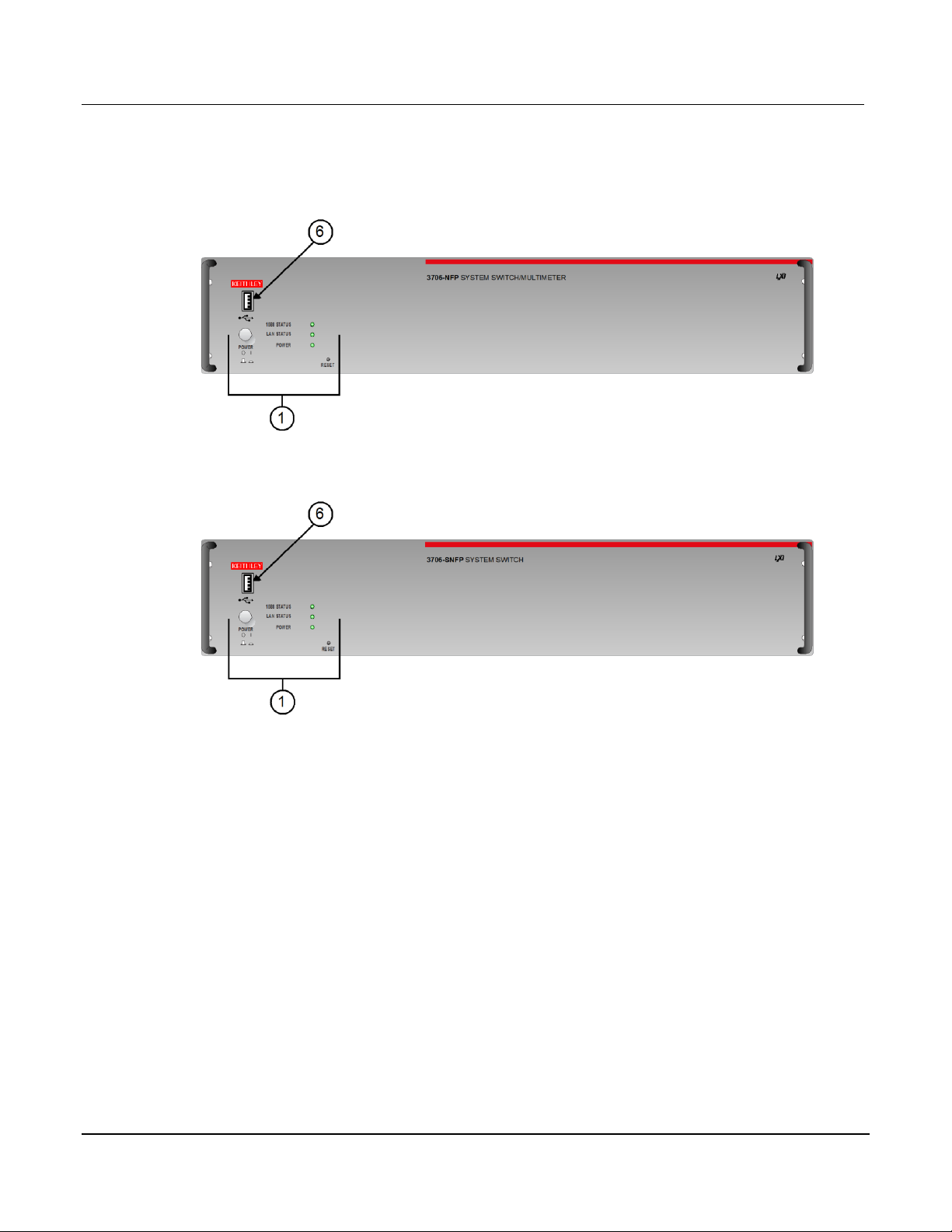
Figure 2-3: Model 3706-NFP System Switch/Multimeter ...................................................... 2-3
Figure 2-4: Model 3706-SNFP System Switch (no DMM) ..................................................... 2-3
Figure 2-5: Active channel display example ......................................................................... 2-4
Figure 2-6: MAIN MENU display .......................................................................................... 2-6
Figure 3-1: Rear panel features ........................................................................................... 3-1
Figure 3-2: Digital I/O port ................................................................................................... 3-3
Figure 3-3: USB connectors ................................................................................................ 3-5
Figure 3-4: Analog backplane connector ............................................................................. 3-5
Figure 3-5: Typical module installation................................................................................. 3-7
Figure 4-1: Multiplexer card display ..................................................................................... 4-11
Figure 4-2: Matrix card display ............................................................................................ 4-12
Figure 4-3: Two-wire function .............................................................................................. 4-14
Figure 4-4: Four-wire function.............................................................................................. 4-15
Figure 5-1: Line cycle synchronization ................................................................................. 5-4
Figure 5-2: DCV connection ................................................................................................ 5-6
Figure 5-3: ACV connection ................................................................................................ 5-6
Figure 5-4: Rear panel to backplane to DMM connect relays schematic ............................... 5-7
Figure 5-5: ACV measurements: sine waves ....................................................................... 5-9
Figure 5-6: ACV measurements: square, pulse, and sawtooth waves .................................. 5-10
Figure 5-7: Two-wire resistance measurements .................................................................. 5-18
Figure 5-8: Four-wire resistance measurement .................................................................... 5-18
Page 16

List of Figures
System Switch/Multimeter
User's Manual
viii
v. A / August 2007
Figure 5-9: Two-wire switching module resistance connection ............................................. 5-19
Figure 5-10: Four-wire switching module resistance connection ........................................... 5-19
Figure 5-11: Enabling offset-compensated ohms ................................................................. 5-21
Figure 5-12: Four-wire Ohm ATTR MENU: OFFSETCOMP ................................................. 5-22
Figure 5-13: Enabling dry-circuit ohms ................................................................................ 5-24
Figure 5-14: Four-wire Ohm ATTR MENU: DRYCIRCUIT .................................................... 5-24
Figure 5-15: Two-wire constant-current source method ....................................................... 5-27
Figure 5-16: Four-wire constant-current source method ....................................................... 5-27
Figure 5-17: Two-wire ratiometric method............................................................................ 5-28
Figure 5-18: Four-wire ratiometric method ........................................................................... 5-29
Figure 5-19: Simplified Dry-Circuit open lead detection schematic ....................................... 5-30
Figure 5-20: Simplified normal four-wire open lead detection schematic .............................. 5-31
Figure 5-21: Simplified Dry-Circuit open V-clamp feedback loop schematic ......................... 5-34
Figure 5-22: Simplified T/C open lead detection schematic .................................................. 5-38
Figure 5-23: Simulated reference junction ........................................................................... 5-40
Figure 5-24: Simulated reference junction switching module ................................................ 5-40
Figure 5-25: Internal reference junction (40 channel switching module) ............................... 5-40
Figure 5-26: Thermistor analog backplane connection ......................................................... 5-42
Figure 5-27: Thermistor switching module connection ......................................................... 5-42
Figure 5-28: Three-wire RTD connections ........................................................................... 5-44
Figure 5-29: Three-wire RTD switching module connections ................................................ 5-44
Figure 5-30: Four-wire RTD connections ............................................................................. 5-45
Figure 5-31: Four-wire RTD switching module connections.................................................. 5-45
Figure 5-32: FREQ and PERIOD input connections ............................................................. 5-49
Figure 5-33: FREQ and PERIOD connections (switching module) ....................................... 5-49
Document Number: 3700S-900-01 Re
Page 17

System Switch/Multimeter
User's Manual
List of Figures
Document Number: 3700S
ix
Figure 5-34: Continuity connections .................................................................................... 5-51
Figure 5-35: Continuity connections using a switching module ............................................. 5-51
Figure 8-1: Fuse location ..................................................................................................... 8-2
Figure 9-1: Model 3720 ....................................................................................................... 9-8
Figure 9-2: D-sub connection information for the Model 3720 .............................................. 9-9
Figure 9-3: Schematic of the Model 3720 ............................................................................ 9-10
Figure 9-4: Sample Model 3720 connection log (1 of 2) ....................................................... 9-11
Figure 9-5: Sample Model 3720 connection log ................................................................... 9-12
Figure 9-6: Model 3721 ....................................................................................................... 9-13
Figure 9-7: D-sub connection information for the Model 3721 .............................................. 9-15
Figure 9-8: Schematic of the Model 3721 in two-pole mode ................................................. 9-16
Figure 9-9: Schematic of the Model 3721 in four-wire common side ohm mode ................... 9-17
Figure 9-10: Model 3721 shield removal .............................................................................. 9-19
Figure 9-11: Model 3721 fuse location ................................................................................. 9-19
Figure 9-12: Sample Model 3721 connection log (1 of 2) ..................................................... 9-20
Figure 9-13: Sample Model 3721 connection log (2 of 2) ..................................................... 9-21
Figure 9-14: Model 3722 ..................................................................................................... 9-22
Figure 9-15: D-sub connection information the Model 3722 ................................................. 9-23
Figure 9-16: Schematic for the Model 3722 ......................................................................... 9-24
Figure 9-17: Sample Model 3722 connection log (1 of 3) ..................................................... 9-25
Figure 9-18: Sample Model 3722 connection log (2 of 3) ..................................................... 9-26
Figure 9-19: Sample Model 3722 connection log (3 of 3) ..................................................... 9-27
Figure 9-20: Model 3723 ..................................................................................................... 9-28
Figure 9-21: D-sub connection information for the Model 3723 ............................................ 9-29
Figure 9-22: Schematic for the Model 3723 in two-pole mode .............................................. 9-30
-900-01 Rev. A / August 2007
Page 18

List of Figures
System Switch/Multimeter
User's Manual
x
01 Rev. A / August 2007
Figure 9-23: Schematic: Model 3723 in one-pole mode ....................................................... 9-31
Figure 9-24: Sample Model 3723 connection log (60 channel)(1 of 2) .................................. 9-32
Figure 9-25: Sample Model 3723 connection log (60 channel)(2 of 2) .................................. 9-33
Figure 9-26: Sample Model 3723 connection log (120 channel)(1 of 4) ................................ 9-34
Figure 9-27: Sample Model 3723 connection log (120 channel)(2 of 4) ................................ 9-35
Figure 9-28: Sample Model 3723 connection log (120 channel)(3 of 4) ................................ 9-36
Figure 9-29: Sample Model 3723 connection log (120 channel)(4 of 4) ................................ 9-37
Figure 9-30: Model 3730 ..................................................................................................... 9-38
Figure 9-31: D-sub connection information for the Model 3730 ............................................ 9-39
Figure 9-32: Schematic of the Model 3730 .......................................................................... 9-39
Figure 9-33: Sample Model 3730 connection log (1 of 3) ..................................................... 9-40
Figure 9-34: Sample Model 3730 connection log (2 of 3) ..................................................... 9-41
Figure 9-35: Sample Model 3730 connection log (3 of 3) ..................................................... 9-42
Figure 9-36: Model 3740 ..................................................................................................... 9-43
Figure 9-37: D-sub connection information for the Model 3740 ............................................ 9-44
Figure 9-38: Schematic for the Model 3740 ......................................................................... 9-45
Figure 9-39: Sample Model 3740 connection log ................................................................. 9-46
Document Number: 3700S-900-
Page 19

In this section:
Overview ........................................................................................................ 1-1
Warranty information ....................................................................................... 1-3
Safety symbols and terms ............................................................................... 1-4
Specifications.................................................................................................. 1-4
Section 1
Introduction
If you have any questions after reviewing this information, please contact your local
Keithley Instruments representative or call one of our Applications Engineers at
1-888-KEITHLEY (1-888-534-8453). You can also contact us through our website at
www.keithley.com.
Overview
The Series 3700 instruments offer scalable, instrument grade switching and multi-channel
measurement solutions that are optimized for automated testing of electronic products and
components. The Series 3700 includes four versions of the Model 3706 system switch
mainframe along with a growing family of plug-in switch and control cards. When the Model
3706 mainframe is ordered with the high performance multimeter, you receive a tightly
integrated switch and measurement system that can meet the demanding application
requirements in a functional test system or provide the flexibility needed in stand-alone data
acquisition and measurement applications.
Page 20
Section
1: Introduction Series 3700 System Switch/Multimeter
User's Manual
1
01 Rev. A / August 2007
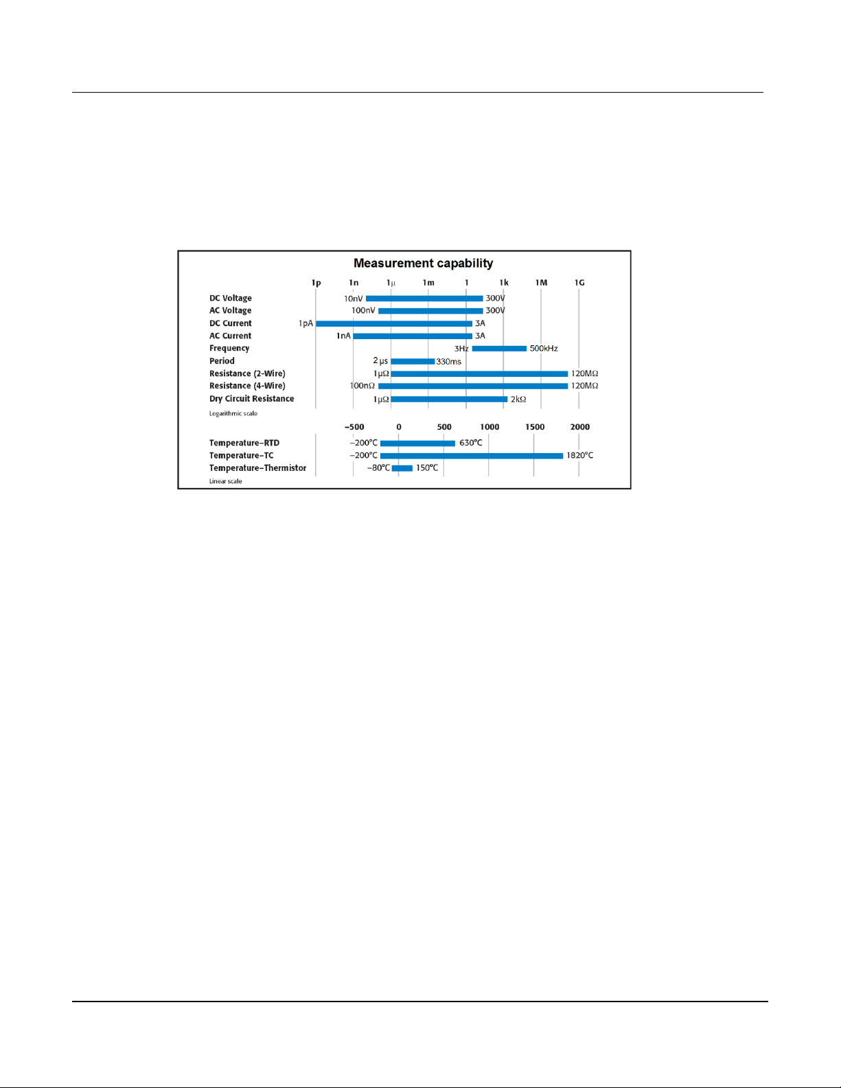
Measure and switching capabilities
The basic measurement capabilities of Series 3700 systems are summarized in the following
figure.
Figure 1-1: DMM measurement capabilities
Reference manual content
Refer to the Series 3700 Reference Manual for specific listing of advanced operation including:
Range
Digits
Rate Bandwidth
Filter
Relative
Math
dB
Buffer
Scanning
Calibration
Also included in the reference manual is a detailed listing of the Instrument Control Library (ICL)
commands.
-2 Document Number: 3700S-900-
Page 21

Series 3700
System Switch/Multim eter User's Manual Section 1: Intro
duction
Document Number: 3700S
-3
Warranty information
Detailed warranty information is located at the front of this manual. Should your Series 3700
require warranty service, contact the Keithley Instruments representative or authorized repair
facility in your area for further information. When returning the instrument for repair, be sure to
complete the service form at the back of this manual and give it to the repair facility with all
relevant information.
NOTE The service form requires the serial number of the Series 3700. The serial number
label is located inside the unit on the bottom panel. The serial number can be viewed
by removing the slot covers and/or switching modules from the mainframe.
WARNING Before removing (or installing) switching modules, make sure you turn off
the Series 3700 and disconnect the line cord. Also, remove any other
external power connected to the instrument or switching module(s).
Failure to remove power before removing (or installing) switching
modules may result in personal injury or death due to electric shock.
Displaying the unit's serial number
To display the serial number on the front panel:
NOTE If the Series 3700 is in remote mode, press the EXIT key once to place the unit in local
mode.
1. When in local mode, press the MENU key.
2. Scroll to the SYSTEM-INFO menu and press the ENTER key.
3. On the SYSTEM INFORMATION menu, scroll to the SERIAL# and press the ENTER key.
The Series 3700 serial number will be displayed.
-900-01 Rev. A / August 2007 1
Page 22
Section
1: Introduction Series 3700 System Switch/Multimeter
User's Manual
1
01 Rev. A / August 2007
Safety symbols and terms
The following symbols and terms may be found on the System Switch/Multimeter or used in this
manual:
The
manual.
The
precautions to avoid personal contact with these voltages.
The
prevent burns.
The WARNING heading used in this manual explains dangers that might result in personal
injury or death. Always read the associated information very carefully before performing the
indicated procedure.
The CAUTION heading used in this manual explains hazards that could damage the unit. Such
damage may invalidate the warranty.
Specifications
Full specifications can be found in Appendix A of this manual. Also, refer to the product data
sheet for System Switch/Multimeter specifications. Check the Keithley Instruments website at
www.keithley.com for the latest updates to the specifications.
symbol indicates that the user should refer to the operating instructions located in the
symbol shows that high voltage may be present on the terminal(s). Use standard safety
symbol on an instrument shows that the surface may be hot. Avoid personal contact to
-4 Document Number: 3700S-900-
Page 23
In this section:
Front panel introduction ................................................................................... 2-1
Display ........................................................................................................... 2-3
Front panel keys ............................................................................................. 2-6
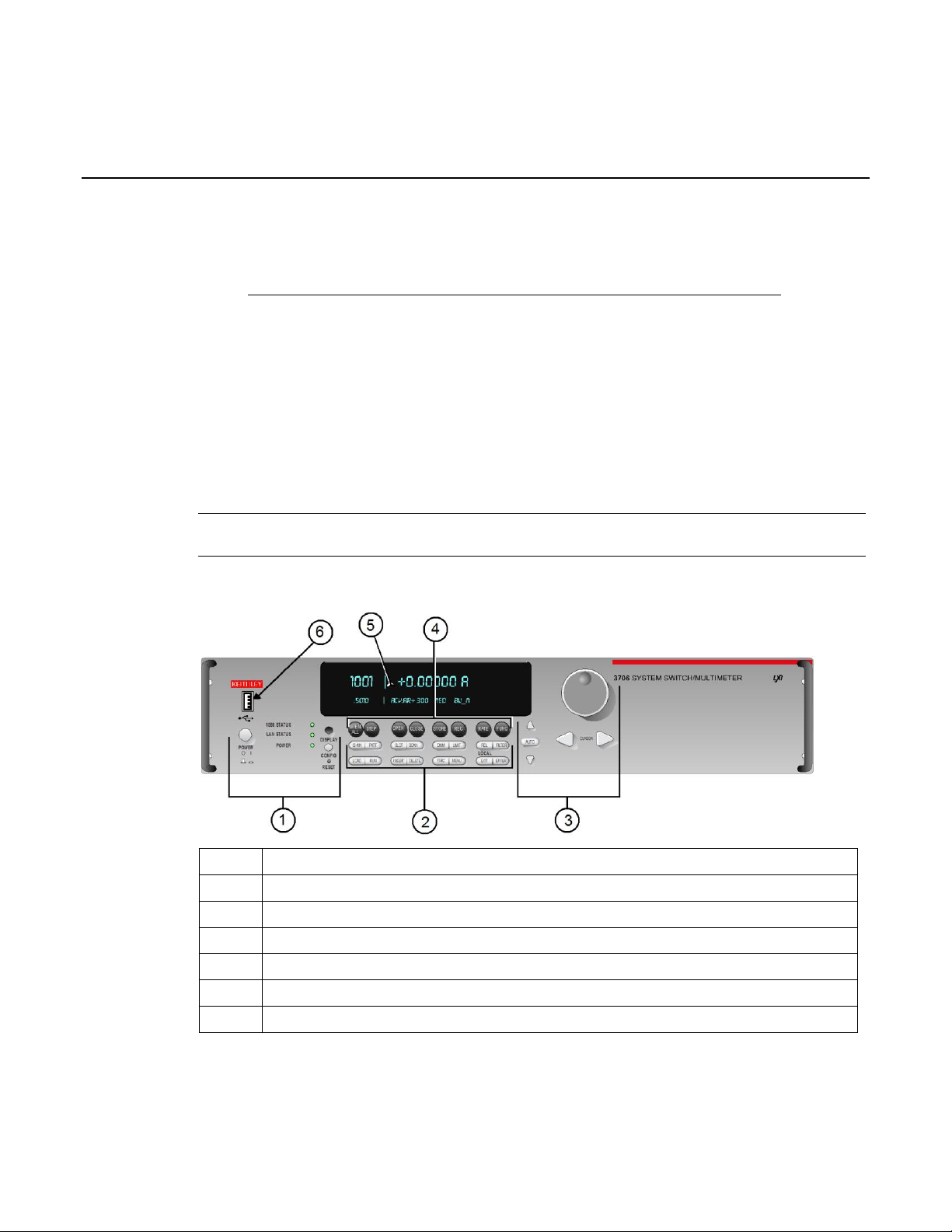
Item
Description
1
Special keys and power switch
2 Operation keys
3 Range, multifunction keys, and wheel (on page 2-17)
4 Function keys
5 Display
6 USB connector (see "USB connectors" on page 3-4)
Section 2
Using the Front Panel
Front panel introduction
Typical Series 3700 front panels are shown below.
NOTE Not all models will have a DMM installed. All DMM related documentation is not
applicable to those models.
Figure 2-1: Model 3706 System Switch/Multimeter
(on page 2-7)
(on page 2-17)
(on page 2-3)
(on page 2-6)
Page 24
Section
2: Using the Front Panel Series 3700 System Switch/Multimeter
User's Manual
2
01 Rev. A / August 2007
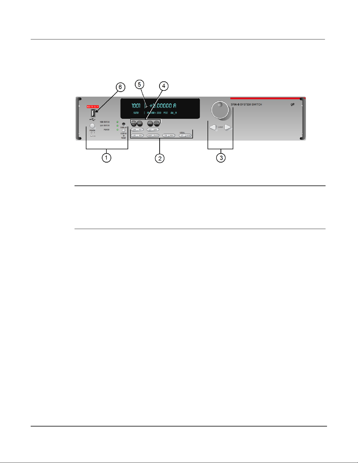
Figure 2-2: Model 3706-S System Switch (no DMM)
NOTE If your model does not have a front panel, please refer to the reference manual for
information on how to change:
1. GPIB address with gpib.address command.
2. LAN configuration using LAN functions. To see current settings for LAN, see the
applicable lan.status.* commands (for example, to see the present IP address of the
Series 3700, send the following command: lan.status.ipaddress.
-2 Document Number: 3700S-900-
Page 25
Series 3700
System Switch/Multim eter User's Manual Section 2:
Using the Front Panel
Document Number: 3700S
-3
Figure 2-3: Model 3706-NFP System Switch/Multimeter
Figure 2-4: Model 3706-SNFP System Switch (no DMM)
Display
The Series 3700 display provides visual information on the present active channel. The display,
with the wheel, provides a means to change the active channel or channel ranges, as well as
access to view and edit the various menus and menu items.
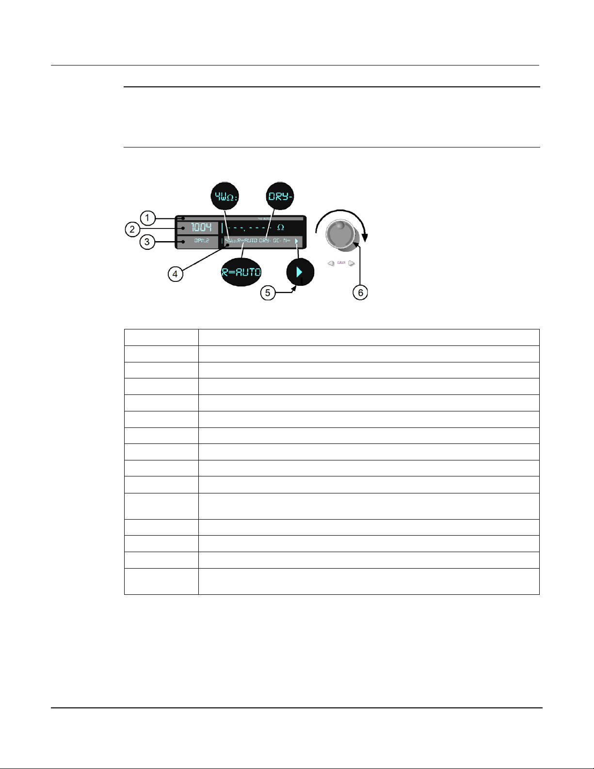
See the following figure for an active channel example. The display has the 4W and AUTO
range annunciators lit (1). Also, the active channel is 1004 (Slot 1 Channel 004). The present
state of the channel is open, and it has two poles (3). The present state of the attributes for this
channel (4) are: 4W function set for AUTO range, dry-circuit ohms disabled (DRY-), offset
compensation off (OC-). Other attributes, such as NPLC, are available for this specific active
channel (1004) as indicated by arrow (5) being lit. These may be viewed by turning the wheel (6)
to scroll through the attribute list.
-900-01 Rev. A / August 2007 2
Page 26
Section
2: Using the Front Panel Series 3700 System Switch/Multimeter
User's Manual
2
Rev. A / August 2007
Annunciator
Description
* (asterisk)
Front panel readings are being stored in the selected reading buffer.
4W 4
ARM Unit armed and ready to use.
AUTO
Auto range enabled for the selected DMM function.
EDIT
Unit in edit mode (for front panel).
FILT Filter enabled for the selected DMM function.
LSTN
Instrument addressed to listen over GPIB.
MATH
mX+b, percent, or reciprocal (1/X) calculation enabled for the selected DMM function.
REL Relative enabled for selected DMM function.
REM Instrument in bus remote mode or web control mode (all interfaces, LAN, GPIB, or
USB).
SMPL
Flashes whenever the DMM has compl
SRQ Service request over GPIB.
TALK
Instrument addressed to talk over GPIB bus.
TRIG
External triggering selected. The TRIG annunciator will blink if taking continuous
triggered readings on front panel.
NOTE Attribute lists, as well as menu lists, that are larger than the display, can be accessed
by turning the wheel (6). Displayed arrows (5) indicate additional attributes (or menu
items, as applicable) are available for access by turning the wheel (6) in the direction
the arrow points. If an arrow (5) is not displayed, there are no additional menu choices
in that direction.
Figure 2-5: Active channel display example
The top line of the display (1) contains the following annunciators:
-wire resistance or RTD temperature reading displayed.
eted a reading.
-4 Document Number: 3700S-900-01
Page 27

Series 3700
System Switch/Multim eter User's Manual Section 2:
Using the Front Panel
Document Number: 3700S
-5
Front panel DMM attribute
Symbol
Values
range
R=
AUTO or n, here n equals the range
nplc N= n, where n equals the nplc
auto delay
AD + for ON, 1 for ONCE, or 0 for OFF
auto zero
AZ +
line sync
LS + for ON or
limit LIM + for a limit enabled or
detector bandwidth
DBW
3, 30, or 300
threshold
THR=
n, where n indicates the threshold
aperture
A= n, where n indicates the aperture setti
dry circuit
DRY + for ON or – for OFF
offset compensation
OC + for ON or
thermocouple sensor K
K_T/C
N/A
thermocouple sensor T
T_T/C
N/A thermocouple sensor E
E_T/C
N/A
thermocouple sensor R
R_T/C
N/A thermocouple sensor S
S_T/C
N/A
th
B_T/C
N/A
thermocouple sensor N
N_T/C
N/A thermistor
THRM
N/A
three
3RTD
N/A
four
4RTD
N/A
simulated reference junction
RJ_SIM
N/A
internal reference junction
RJ_INT
N/A
external reference junction
RJ_EXT
N/A
The bottom line of the display (4) contains the attribute symbols. The symbols that appear are
dependent on whether the attribute exists for the selected function. If the symbol has also
contains a value, the third column in the table indicates the value definition. The following table
indicates the DMM attribute symbols that may appear on the front panel.
ermocouple sensor B
-wire RTD
-wire RTD
for ON or – for OFF
– for OFF
– for limits disabled
ng
– for OFF
NOTE To access the main menu, press the MENU key.
-900-01 Rev. A / August 2007 2
Page 28
Section
2: Using the Front Panel Series 3700 System Switch/Multimeter
User's Manual
2
01 Rev. A / August 2007
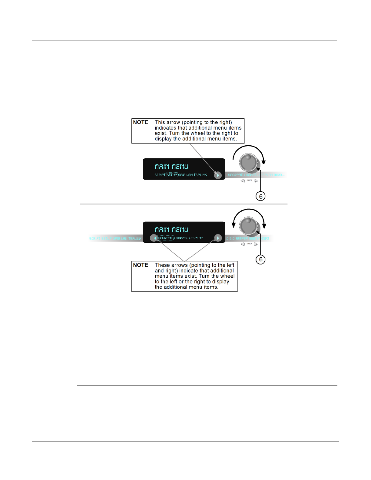
See the following figure for a menu example. In the example, the MAIN MENU is displayed.
Turn the wheel (6) or press the cursor keys, to scroll through the available menu items. In the
following figure's first display, there is a right arrow indicator. This indicates there are additional
menu items to the right. In figure's second display, both right and left arrows are active indicating
there are additional items in both directions. To select the highlighted (flashing) menu item,
press the wheel (or press the ENTER key).
Figure 2-6: MAIN MENU display
Front panel keys
Special keys and power switch
POWER switch
-6 Document Number: 3700S-900-
Press this switch to turn the Series 3700 on (I); press it again to turn it off (O).
DISPLAY key
Press this key to toggles between main and user display modes.
Page 29

Series 3700
System Switch/Multim eter User's Manual Section 2:
Using the Front Panel
Document Number: 3700S
-7
CONFIG key
Use this key to access the an attribute menu that enables you to configure channels, channel
patterns, DMM functions, or settings, reading buffer, scans, and other operations. Refer to the
following for additional information:
CHAN key configuration (on page 2-8)
PATT key configuration (on page 2-9)
SCAN key configuration (on page 2-10)
DMM key configuration (on page 2-11)
LIMIT key configuration (on page 2-14)
REL key configuration (on page 2-14)
FILTER key configuration (on page 2-15)
RESET switch
Use this switch to restore the Series 3700 factory default LAN settings. Refer to the reference
manual LAN functions (lan.config.x, where x represents the specific command) for factory
default information.
Operation keys
CHAN key
Pressing this key opens the CHANNEL ACTION MENU that contains the following menu items:
OPEN: This menu item opens the specified channels for switching aspects. Related
Instrument Control Library (ICL) command: channel.open
CLOSE: This menu item closes specified channels. These closures are appended to the
already closed channels. Related ICL command: channel.close
EXCLOSE: This menu item closes the specified items so they are exclusively closed.
Related ICL commands: channel.exclusiveclose, channel.exclusiveslotclose
EXSLOTCLOSE: This menu item exclusively closes specified channels on the specified
slots. Related ICL command: channel.exclusiveslotclose
RESET: This menu item resets channel and channel pattern aspects of the system to
factory default settings. Related ICL command: channel.reset
-900-01 Rev. A / August 2007 2
Page 30

Section
2: Using the Front Panel Series 3700 System Switch/Multimeter
User's Manual
2
01 Rev. A / August 2007
CHAN key configuration
Pressing the CONFIG key and then the CHAN key opens the CHANNEL ATTRibute MENU.
This menu contains:
LABEL: This menu item sets the label associated with the channels specified. Related
ICL command: channel.setlabel. From the front panel, the label can be up to 12
characters. Remotely, the label may be up to 20 characters.
BACKPLANE: This menu item opens the BACKPLANE MENU. Use this menu to add or
remove backplane channels from the channels specified. Related ICL command:
channel.setbackplane
FORBID: This menu item prevents the closing of the channels specified. Related ICL
command: channel.setforbidden
POLE: This menu item sets the number of poles for the channels specified. Related ICL
command: channel.setpole
DELAY: This menu sets additional delay time for channels specified. Related ICL
command: channel.setdelay
COUNT: This menu item displays closure cycles for the channels specified. Related ICL
command: channel.getcount
DMM_CONFIG: This menu item sets the DMM configuration associated with the
channels specified. Related ICL command: dmm.setconfig
PATT key
Pressing this key opens the PATTERN ACTION MENU that contains the following menu items:
OPEN: This menu item opens the specified channel pattern for switching aspects.
Related ICL command: channel.open
CLOSE: This menu item closes specified channel pattern. These closures are appended
to the already closed channels. Related ICL command: channel.close
EXCLOSE: This menu item closes the specified items so they are exclusively closed.
Related ICL command: channel.exclusiveclose
EXSLOTCLOSE: This menu item exclusively closes specified channels on the specified
slots. Related ICL command: channel.exclusiveslotclose
CREATE: This menu item creates a channel pattern from a snapshot and associates it
with the specified name. From the front panel, the pattern name can be up to 12
characters. Remotely, the pattern name may be up to 20 characters. Note that if no
patterns exist in the system when the PATT key is pressed, then CREATE will be the
only menu item displayed. Related ICL commands: channel.pattern.snapshot
-8 Document Number: 3700S-900-
Page 31

Series 3700
System Switch/Multim eter User's Manual Section 2:
Using the Front Panel
Document Number: 3700S
-9
VIEW: This menu item shows the channels associated with the pattern. Note that if no
patterns exist in the system when the PATT key is pressed, then this will be the only
menu item displayed in the PATTERN ACTION MENU. Related ICL command:
channel.pattern.getimage
DELETE: This menu item deletes a channel pattern. Related ICL command:
channel.pattern.delete
RESET: This menu item resets channel pattern aspects of the system to factory default
settings. Resetting a channel pattern will cause each channel and backplane relay of the
pattern image to be reset back to factory default settings. Also, the pattern will be deleted
because resetting a channel causes any patterns that contain a channel being reset will
be deleted. Related ICL command: channel.reset
If patterns (or a pattern) have already been created, pressing this key once will allow you to
scroll through and select a pattern. Pressing this key a second time opens the PATTERN
ACTION MENU (as described above).
PATT key configuration
Pressing the CONFIG key and then the PATT key opens the PATTERN ATTRibute MENU. This
menu contains the following item:
DMM_CONFIG: This menu item sets the DMM configuration associated with the
channels specified. Related ICL command: dmm.setconfig
SLOT key
Press this key to display installed card(s) and instrument information, as well as main system
information. The information displayed includes firmware revisions of both main and installed
components. After pressing this key, scroll through all available instruments, including the
internal DMM.
SCAN key
If a scan list is present, this key opens the SCAN ACTION MENU that contains the following
menu items:
NOTE Use the INSERT key to create and add the present active channel to the scan list.
EXECUTE: This menu item runs the scan. Related ICL command: scan.execute
CREATE: This menu item displays following message: Use <INSERT> key
LIST: This menu item displays the scan list (turn the wheel to scroll). Related ICL
command: scan.list
CLEAR: This menu item clears the scan list. Related ICL command: scan.create (send
with an empty string)
RESET: This menu item resets the scan settings to factory default values. Related ICL
command: scan.reset
-900-01 Rev. A / August 2007 2
Page 32

Section
2: Using the Front Panel Series 3700 System Switch/Multimeter
User's Manual
2
01 Rev. A / August 2007
SCAN key configuration
Pressing the CONFIG key and then the SCAN key opens the "SCAN ATTR MENU" that
contains:
ADD: This menu item instructs how to add an additional list of channels and/or channel
patterns to scan. When it displays "Use <INSERT> key", with selected channel or
channel pattern for adding to scan list on front panel, press the INSERT key when on the
main display. Related ICL command: scan.add
BYPASS: This menu item enables or disables bypassing the first item in the scan.
Related ICL command: scan.bypass
MODE: This menu item sets the scan.mode value to one of the following:
scan.MODE_OPEN_ALL or 0 (default setting),
scan.MODE_OPEN_SELECTIVE or 1
scan.MODE_FIXED_ABR or 2.
See related ICL command for definitions. Related ICL command: scan.mode
MEAS_CNT: This menu item sets the measure count value. Related ICL command:
scan.measurecount
SCAN_CNT: This menu item sets the scan count value. Related ICL command:
scan.scancount
DMM key
Opens the DMM ACTION MENU that contains the following menu items:
MEASURE: This menu item takes measurements on the digital multimeter (DMM)
without using the trigger model. Related ICL command: dmm.measure
COUNT: This menu item indicates the number of measurements to take when a
measurement is requested. Related ICL command: dmm.measurecount
LOAD: This menu item recalls a user or factory DMM configuration. Related ICL
command: dmm.configure.recall
SAVE: This menu item creates a DMM configuration with the pertinent attributes based
on the selected function and associates it with the specified name. Related ICL
command: dmm.configure.set
OPEN: This menu item opens the specified channel and/or channel pattern. Related ICL
command: dmm.open
CLOSE: This menu item closes the specified channel or channel pattern in preparation
for a DMM measurement. Related ICL command: dmm.close
RESETFUNC: This menu item returns DMM aspects of the system for the active function
only. Related ICL command: dmm.reset
RESETALL: This menu item returns the DMM functions instruments to the default
settings. Related ICL command: dmm.reset
-10 Document Number: 3700S-900-
Page 33

Series 3700
System Switch/Multim eter User's Manual Section 2:
Using the Front Panel
Document Number: 3700S
11
DMM key configuration
Pressing the CONFIG key and then the DMM key opens a DMM attribute menu for the active
function. For example, if the DCV function is active, pressing the CONFIG key and then the
DMM key opens the DC VOLT ATTR MENU.
Each function only has access to the applicable attributes for that function. Brief definitions of
the available attributes are contained in the following paragraphs. Refer to the appropriate ICL
contained in the reference manual for additional attribute information (Instrument Control Library
(ICL)).
APERTURE
Configures the aperture setting for the active DMM function in seconds. Related ICL command:
dmm.aperture
AUTODELAY
Configures the auto delay setting for the active DMM function. Related ICL command:
dmm.autodelay
AUTORANGE
AUTOZERO
Configures the auto zero setting for the DMM. Related ICL command: dmm.autozero
Configures the auto range setting for the DMM. Related ICL command: dmm.autorange
DBREF
Configures the DB reference setting for the DMM in volts. Related ICL command:
dmm.dbreference
DIGITS
Configures the display digits setting for the selected DMM function. Related ICL command:
dmm.displaydigits
DRYCIRCUIT
Configures the dry circuit setting for the selected DMM function. Related ICL command:
dmm.drycircuit
FILTER
Opens the FILTER MENU for the selected DMM function. See FILTER key configuration (on
page 2-15).
FUNC
Pressing this key selects the active DMM function for the channel. Related ICL command:
dmm.func
-900-01 Rev. A / August 2007 2-
Page 34

Section
2: Using the Front Panel Series 3700 System Switch/Multimeter
User's Manual
2
01 Rev. A / August 2007
INPUTDIV
LIMIT
Opens the LIMIT MENU for the selected DMM function. See LIMIT key configuration (on page 2-
14).
Enables or disables the 10M ohm input divider. Related ICL command: dmm.inputdivider
LINESYNC
Attribute configuring whether line sync is used during the measurement. Related ICL command:
dmm.linesync
MATH
Selecting the MATH menu item opens the MATH MENU. Items contained in this menu are as
follows:
ENABLE: Enable or disable math operation on measurements. Related ICL command:
dmm.math.enable
FORMAT: Specifies the math operation to perform on measurements. Related ICL
command: dmm.math.format
BFACTOR: Specifies the offset for the y = mx + b operation. Related ICL command:
dmm.math.mxb.bfactor
MFACTOR: Specifies the scale factor for the y = mx + b operation. Related ICL
command: dmm.math.mxb.mfactor
MXBUNITS: Specifies the unit character for the y = mx + b operation. Related ICL
command: dmm.math.mxb.units
PERCENT: Specifies the constant to use for the percent operation. Related ICL
NPLC
command: dmm.math.percent
OFFSETCOMP
Configures the offset compensation setting for the DMM. Related ICL command:
dmm.offsetcompensation
Configures the integration rate in line cycles for the DMM. Related ICL command: dmm.nplc
-12 Document Number: 3700S-900-
Page 35

Series 3700
System Switch/Multim eter User's Manual Section 2:
Using the Front Panel
Document Number: 3700S
13
OPENDETECT
Configures the state of the thermocouple or four-wire ohms open detector being used. Related
ICL command: dmm.opendetector
RANGE
REL
Opens the REL MENU for the selected DMM function. See REL key configuration (on page 2-
14).
Configures the range of DMM for the selected function. Related ICL command: dmm.range
THERMO
Selecting the THERMO menu item opens the THERMO MENU. Items contained in this menu
are as follows:
REF JUNCTION: Allows selection of the Reference Junction to use. Available choices
are: SIMULATED, EXTERNAL, or INTERNAL. Related ICL command: dmm.refjunction
SIMREF: Specifies the simulated reference temperature for thermocouples. Related ICL
command: dmm.simreftemperature
THERMISTOR: Specifies the type of thermistor. Related ICL command: dmm.thermistor
COUPLE: Specifies the thermocouple type. Related ICL command: dmm.thermocouple
TRANSDUCER: Selects the transducer type (THERMOCOUPLE, THERMISTOR, 3RTD,
or 4RTD). Related ICL command: dmm.transducer
THREERTD: Specifies the type of 3-wire RTD. Related ICL command: dmm.threertd
FOURRTD: Specifies the type of 4-wire RTD. Related ICL command: dmm.fourrtd
USER: Specifies USER type of RTD (ALPHA, BETA, DELTA, or ZERO). Related ICL
THRESHOLD
commands: dmm.rtdalpha, dmm.rtdbeta, dmm.rtddelta, dmm.rtdzero
Configures the threshold range. Related ICL command: dmm.threshold
UNITS
Configures the units for voltage and temperature measurements. Related ICL command:
dmm.units
-900-01 Rev. A / August 2007 2-
Page 36

Section
2: Using the Front Panel Series 3700 System Switch/Multimeter
User's Manual
2
01 Rev. A / August 2007
LIMIT key
Pressing this key will cycle through the four combinations of limit state settings (Limit1 and
Limit2 off, Limit1 on and Limit2 off, Limit1 off and Limit2 on, Limit1 and Limit2 on).
LIMIT key configuration
Pressing the CONFIG key and then the LIMIT key opens the LIMIT MENU. Select LIMIT 1 or
LIMIT 2 to open the desired LIMIT 1 or 2 MENU. These menus contain the following menu
items:
ENABLE: This menu item enables or disables limit testing. Related ICL command:
dmm.limit[Y].enable
CLEAR: This menu item clears the test results of the limit. Related ICL command:
dmm.limit[Y].clear
AUTOCLEAR: This menu item sets indicates if the limit should be cleared automatically
or not. Related ICL command: dmm.limit[Y].autoclear
LOWVAL: This menu item sets the low limit value. Related ICL command:
dmm.limit[Y].low.value
LOWFAIL: This menu item queries for the low test results of the limit. Related ICL
command: dmm.limit[Y].low.fail
HIGHVAL: This menu item sets the high limit value. Related ICL command:
dmm.limit[Y].high.value
HIGHFAIL: This menu item queries for the high test results of limit. Related ICL
command: dmm.limit[Y].high.fail
REL key
Pressing this key enables/disables relative for selected function. Causes REL annunciator to
light when enabled. Also see Relative in the reference manual.
REL key configuration
Pressing the CONFIG key and then the REL key opens the RELATIVE OFFSET MENU. This
menu contains the following menu items:
ACQUIRE: This menu item acquires an internal measurement to store as the REL level
value. Related ICL command: dmm.rel.acquire
ENABLE: This menu item enables or disables relative measurement control for the
DMM. Related ICL command: dmm.rel.enable
LEVEL: This menu item sets a specific offset value to use for relative measurements for
the DMM. Related ICL command: dmm.rel.level
-14 Document Number: 3700S-900-
Page 37

Series 3700
System Switch/Multim eter User's Manual Section 2:
Using the Front Panel
Document Number: 3700S
15
FILTER key
Pressing this key enables/disables filter for selected function. When the filter is enabled, the
FILT annunciator will light. Also see Filter in the reference manual.
FILTER key configuration
Pressing the CONFIG key and then the FILTER key opens the FILTER MENU. This menu
contains the following menu items:
ENABLE: This menu item enables or disables filtered measurements for the selected
DMM function. Related ICL command: dmm.filter.enable
COUNT: This menu item indicates the filter count setting for the selected DMM function.
Related ICL command: dmm.filter.count
TYPE: This menu item indicates the filter averaging type for the DMM measurements on
the selected DMM functions (MOVING or REPEAT). Related ICL command:
dmm.filter.type
WINDOW: This menu item indicates the filter window for the DMM measurements
(0-10% in 0.1% increments). Related ICL command: dmm.filter.window
FUNC
Pressing this key selects the active DMM function for the channel. Related ICL command:
dmm.func
FUNC key configuration
Pressing the CONFIG key and then the FUNC key allows viewing of the available functions and
then selection of the active function. Turn the wheel (or press the cursor keys) to scroll through
available functions. Press the wheel (or the ENTER key) to make the displayed function active.
NOTE When using just the FUNC key (not in configuration mode of the FUNC key as this
topic is describing), the selected function takes effect immediately as you scroll though
the available functions. While in the configuration mode of the FUNC key, the function
takes effect for the highlighted function only when ENTER key is pressed (the function
does not change while scrolling).
LOAD key
Loads scripts, along with Lua chunks added with display.loadmenu.add for execution. This key
opens the LOAD TEST menu which contains the following menu items:
USER: This menu item provides access to Lua chunks specified by
display.loadmenu.add (not scripts).
SCRIPTS: This menu item provides access to scripts created by the user. The scripts
can be directly executed.
RUN key
Pressing this key runs last selected script or load menu item.
-900-01 Rev. A / August 2007 2-
Page 38

Section
2: Using the Front Panel Series 3700 System Switch/Multimeter
User's Manual
2
01 Rev. A / August 2007
INSERT key
DELETE key
Pressing this key appends the present channel to the scan list.
Pressing this key deletes the present channel (including function) from the scan list. If the
present channel is not contained in the scan list, no error is reported.
TRIG key
Pressing this key triggers a measurement equivalent to the dmm.measure command.
MENU key
Pressing this key opens the MAIN MENU that contains the following menu items:
SCRIPT: Opens the SCRIPT menu that contains LOAD and SAVE menu items.
SETUP: Opens the SETUP MENU that contains SAVE, RECALL, POWERON, and
RESET menu items.
GPIB: Opens the GPIB MENU that contains ADDRESS and ENABLE menu items.
LAN: Opens the LAN MENU that contains STATUS, CONFIG, APPLY, RESET, and
ENABLE menu items.
TSPLINK: Opens the TSPLINK MENU that contains NODE and RESET menu items.
UPGRADE: Questions whether or not the unit is to be upgraded.
CHANNEL: This menu item opens the CONNECT MENU that allows you to select a rule
(BBM, MBB, or OFF), or to connect sequentially (ON or OFF setting). Related ICL
command: channel.connectrule
DISPLAY: Opens the DISPLAY menu. Selecting the TEST item opens the DISPLAY
TESTS MENU which contains KEYS and DISPLAY-PATTERNS menu items. Use KEYS
to verify the operation of the keys. Use DISPLAY-PATTERNS to verify each segment of
the display.
DIGIO: Opens the DIGIO I/O menu that is used to set DIGIO-OUTPUT and WRITE-
PROTECT menu items.
BEEPER: Use to enable or disable the beeper, along with selection KEYCLICK option.
SYSTEM-INFO: Opens the SYSTEM INFORMATION menu that can query FIRMWARE,
SERIAL#, and CAL information.
EXIT key
Cancels the selection and moves back to the measurement display.
ENTER key
Pressing this key accepts selection, moves to next choice, or back to measurement display.
NOTE Pressing the wheel performs the same function as the ENTER key.
-16 Document Number: 3700S-900-
Page 39

Series 3700
System Switch/Multim eter User's Manual Section 2:
Using the Front Panel
Document Number: 3700S
17
Range, multifunction keys, and wheel
Range keys
▲▼ Selects the next higher or lower measurement range for the selected function when on
measurement display.
To set the range, use the RANGE keys ▲ or ▼. If the Series 3700 displays the overflow
message on a particular range, select a higher range until an on-range reading is displayed. Use
the lowest range possible without causing an overflow to ensure best accuracy and resolution.
For details see Auto ranging over the front panel in the reference manual.
AUTO key
Enables or disables autorange for the selected function, and causes the AUTO annunciator to
light when enabled.
CURSOR keys
◄ CURSOR ► Use the CURSOR arrows in a menu to control cursor position for making
selections or changing values.
Wheel
Turn the wheel to scroll to the desired menu option or to change the value of the selected
numeric parameter. Also, press the wheel to cause the same function as pressing the ENTER
key. Also see ENTER key (on page 2-16). Turn the wheel to scroll to the desired digit location to
edit, press the wheel to enter edit mode, and then turn the wheel to increase or decrease the
value.
NOTE When changing a multiple character value, such as an IP address or channel pattern
name, press the wheel to enter edit mode, rotate the wheel to change the characters
value as desired, but do not leave edit mode. Use the cursor keys to scroll to the other
characters and use the wheel to change their value as needed. Press the ENTER key
when finished changing all the characters.
Function keys
OPEN ALL key
Opens all closed channels.
STEP key
Steps through channels associated with the defined scan list; sends a trigger after each
channel.
-900-01 Rev. A / August 2007 2-
Page 40

Section
2: Using the Front Panel Series 3700 System Switch/Multimeter
User's Manual
2
01 Rev. A / August 2007
OPEN key
CLOSE Key
Opens selected channels or channel pattern.
Closes specified channels or channel pattern.
STORE key
Opens the RD BUFF ACTION MENU. This menu contains:
CREATE: Allows creation of a reading buffer, or allows you to select a previously
created reading buffer. When a new buffer is created, you can set the number of
readings to store and then select the buffer. Related Instrument Control Library (ICL)
command: dmm.makebuffer
SELECT: Allows you to select a previously created reading buffer. Related Instrument
Control Library (ICL) command: dmm.measure
CLEAR: Removes readings from a previously created buffer.
SAVE: Allows you to save a previously created reading buffer to a USB flash drive (flash
drive must be installed and have enough available space).
DELETE: Allows you to delete a previously created reading buffer from the system. All
data associated with deleted buffer will be lost. Equivalent to setting the reading buffer
variable name to nil over bus (ICL command).
STORE key configuration
With a buffer selected, pressing the CONFIG key and then the STORE key opens the RD
BUFFER ATTR MENU. This menu contains the following menu items:
CAPACITY: Maximum number of readings that can be stored.
COUNT: Actual number of readings stored.
APPEND: Places readings buffer in append mode.
RECall key
Displays stored readings and buffer statistics for selected reading buffer. Use the ◄ CURSOR
► keys or turn the wheel to navigate through buffer.
RATE key
-18 Document Number: 3700S-900-
Sets measurement speed (fast, medium, or slow) for the active or selected function.
Page 41

Series 3700
System Switch/Multim eter User's Manual Section 2:
Using the Front Panel
Document Number: 3700S
19
FUNCtion key
This key select the active function by cycling through the following list as listed. Each press of
the FUNC key has the DMM and configured to the next function in the list:
dcvolts: DC voltage
acvolts: AC voltage
dccurrent: DC current
accurrent: AC current
twowireohms: Two-wire ohm (resistance)
fourwireohms: Four-wire ohm (resistance)
commonsideohms: Common-side ohm (resistance)
frequency: Frequency
period: Period
continuity: Continuity
temperature: Temperature
-900-01 Rev. A / August 2007 2-
Page 42

Page 43

In this section:
Rear panel summary ....................................................................................... 3-1
Rear panel connections ................................................................................... 3-2
Switching module installation and connections ................................................. 3-6
Module installation .......................................................................................... 3-6
Bus operation .................................................................................................. 3-10
Power-up ........................................................................................................ 3-11
Item
Description
1
Analog backplane fuse (see "Analog backplane AMPS fuse" on page 3-2)
2
Slots (6 places)
3
TSP-link® connectors (2 places) (see "TSP-Link connector" on page 3-2)
4
Instrument fuse
5
Power connector
6
Digital I/O port
7
GPIB connector
8
Ethernet connector (see "Ethernet connector (RJ-45)" on page 3-4)
9
USB connector
10 Analog backplane connector (on page 3-5)
Section 3
Rear Panel
Rear panel summary
Figure 3-1: Rear panel features
(see "Slots" on page 3-2)
(on page 3-2)
(on page 3-2)
(on page 3-3)
(on page 3-4)
(see "USB connectors" on page 3-4)
Page 44

Section
3: Rear Panel Series 3700 System Switch/Multimeter
User's Manual
3
01 Rev. A / August 2007
Rear panel connections
Analog backplane AMPS fuse
FOR CONTINUED PROTECTION AGAINST FIRE HAZARD, REPLACE FUSE WITH SAME
Slots
TSP-Link connector
TYPE AND RATING (3A / 250V). See Fuse replacement (on page 8-1) for details.
Use any of the six slots of the Keithley Instruments Series 3700 for the switching modules.
When a module is not installed, make sure to cover the slot with a slot cover. For additional
information on an installed module, press the SLOT key (on page 2-9).
Instrument fuse
Use with TSP-link cable to expand system.
FOR CONTINUED PROTECTION AGAINST FIRE HAZARD, REPLACE FUSE WITH SAME
TYPE AND RATING (1.25A / 250V). See Fuse replacement (on page 8-1) for details.
Power connector
Using the supplied line cord, connect to a grounded AC power outlet. See Line power
connection (on page 3-11) for connection details.
-2 Document Number: 3700S-900-
Page 45

Series 3700
System Switch/Multim eter User's Manual Section 3:
Rear Panel
Document Number: 3700S
-3
Pin
Description
1
...
9
Digital I/O #1
...
Digital I/O #9
10
...
14
Digital I/O #10 (High Current Pins see Note)
...
Digital I/O #14 (High Current Pins see Note)
15
Ground
22 V EXT
23 V EXT
24 NC (no connectio
25 V EXT
Digital I/O port
The Series 3700 has a digital input/output port that can be used to control external digital
circuitry. For example, a handler that is used to perform binning operations can be used with a
Digital I/O port. The Digital I/O port is a standard female DB-25 connector.
Figure 3-2: Digital I/O port
-21
n)
NOTE High Current Pins (10-14) can be used for binning applications or for external relays.
Connecting cables
Use a cable equipped with a standard male DB-25 connector (Keithley Instruments part number
CA-126-1).
-900-01 Rev. A / August 2007 3
Page 46

Section
3: Rear Panel Series 3700 System Switch/Multimeter
User's Manual
3
01 Rev. A / August 2007
Digital I/O lines (pins 1 through 14)
The port provides 14 digital I/O lines. Each output is set high (+5V) or low (0V) and can read
high or low logic levels.
+5V output (pins 22, 23, and 25)
The Digital I/O Port provides a +5V output that is used to drive external logic circuitry. Maximum
current output for this line is 600mA. This line is protected by a self-resetting fuse (one hour
recovery time).
GPIB connector
For GPIB communication, connect to GPIB port of computer using an IEEE-488 cable (Keithley
Instruments Model 7007).
Ethernet connector (RJ-45)
For Ethernet communication, connect to Ethernet port of a computer, or to a hub or receptacle
of an Ethernet system.
To connect the Series 3700 directly to a computer, use an Ethernet cross-over cable (RJ-45,
male/male).
To connect the Series 3700 to an Ethernet system hub or receptacle, use a standard Ethernet
cable (RJ-45, male/male).
USB connectors
The downstream USB-2.0 receptacle (Type B) located on the rear panel connects to a host. The
front panel has an upstream USB-2.0 connector (Type A) that connects to a user supplied USB
flash drive.
Use the rear connector to communicate with the instrument over USB by sending the desired
commands. Use the front panel connector to insert a USB flash drive for saving or loading
reading buffers, user setups, or scripts. See the Reference Manual for more information on
reading buffers, user setups and scripts.
-4 Document Number: 3700S-900-
Page 47

Series 3700
System Switch/Multim eter User's Manual Section 3:
Rear Panel
Document Number: 3700S
-5
Description
Pin Description
Pin
Analog backplane 3
5 DMM
4
Analog backplane 3
6 DMM
3
Analog backplane 4
7 DMM
2, 9
Analog backplane 4
8 DMM
1
Analog backplane 5-HI
12
AMP
2, 9
Analog backplane 5
13
AMP 10, 11
Analog backplane 6-HI
14
Analog backplane 6
15
Figure 3-3: USB connectors
Analog backplane connector
Refer to the following figure for analog backplane connector information. See Connections (on
page 3-8) before making any connections.
Figure 3-4: Analog backplane connector
The table below contains pin numbers and descriptions for the analog backplane connector.
-HI
-LO
-HI
-LO
-LO
-LO
-900-01 Rev. A / August 2007 3
-SLO
-SHI
-LO
-HI
-LO
Page 48

Section
3: Rear Panel Series 3700 System Switch/Multimeter
User's Manual
3
01 Rev. A / August 2007
Switching module installation and connections
In order to exercise close/open operations explained in this section, a switching module (or
pseudocard) must be installed in the mainframe. A switching module can be installed by the
user, however external connections to the switching module are only to be performed by
qualified service personnel.
WARNING To prevent electric shock that could result in injury or death, NEVER
handle a switching module that has power applied to it:
• Before installing (or removing) a switching module, make sure the Series
3700 is turned off and disconnected from line power.
• If the switching module is already connected to a device under test
(DUT), make sure power is removed from all external circuitry.
NOTE For inexperienced users, it is recommended that DUT and external circuitry not be
connected to switching modules. This will allow you to exercise safe close/open
operations without the dangers associated with live test circuits.
Module installation
WARNING Slot covers must be installed on unused slots to prevent personal contact
Perform the following steps to install a switching module into the Series 3700 mainframe:
1. Turn the Series 3700 off and disconnect the power line cord and any other cables
connected to the rear panel.
2. Position the Series 3700 so that you are facing the rear panel.
3. Remove the slot cover plate from the desired mainframe slot. Retain the plate and screws
for future use.
4. With the top cover of the switching module facing up, align the module's card edge into the
slot's card guide and slide in the module. For the last ¼ inch or so, press in firmly to mate
the module connector to the mainframe connector.
5. On each side of the module, there is a mounting screw. Tighten these two screws to secure
the module to the mainframe. Do not overtighten.
6. Reconnect the power line cable and any other cables to the rear panel.
with high voltage circuits.
-6 Document Number: 3700S-900-
Page 49

Series 3700
System Switch/Multim eter User's Manual Section 3:
Rear Panel
Document Number: 3700S
-7
Item
Description
1 Card guide (part of Series 3700)
2 Module
3 Card edge (part of module)
4 Mounting screw (part of module)
7. Press the SLOT key (on page 2-9) to see the model numbers, description, and the firmware
revision of the installed switching module(s), along with the mainframe firmware and DMM (if
present).
Figure 3-5: Typical module installation
-900-01 Rev. A / August 2007 3
Page 50

Section
3: Rear Panel Series 3700 System Switch/Multimeter
User's Manual
3
01 Rev. A / August 2007
Connections
WARNING Connection information for switching modules is intended for qualified
service personnel. Do not attempt to connect DUT or external circuitry to a
switching module unless qualified to do so.
To prevent electric shock that could result in serious injury or death,
comply with these safety precautions:
Before making or breaking any connections to the switching module,
make sure the Series 3700 is turned off and power is removed from all
external circuitry.
Do not connect signals that will exceed the maximum specifications of
any installed switching module.
If both the rear analog backplane connector of the Series 3700 and the
switching module terminals are connected at the same time, the test lead
insulation must be rated to the highest voltage that is connected. For
example, if 300V is connected to the analog backplane connector, the test
lead insulation for the switching module must also be rated for 300V.
Dangerous arcs of an explosive nature in a high energy circuit can cause
severe personal injury or death. If the multimeter is connected to a high
energy circuit when set to a current range, low resistance range, or any
other low impedance range, the circuit is virtually shorted.
Dangerous arcing can result (even when the multimeter is set to a voltage
range) if the minimum voltage spacing is reduced in the external
connections. For details about how to safely make high energy
measurements, see High-energy circuit safety precautions (on page 5-2).
As described in the International Electrotechnical Commission (IEC)
Standard IEC 664, the Series 3700 is Installation Category I and must not
be connected to mains.
-8 Document Number: 3700S-900-
Page 51

Series 3700
System Switch/Multim eter User's Manual Section 3:
Rear Panel
Document Number: 3700S
-9
Pseudocards
You can perform open/close/scan operations and configure your system without having an
actual switching module installed in your Series 3700. Using remote programming, you can
assign a pseudocard to an empty switching module slot, allowing the Model 3700S to operate as
if a switching module were installed.
A pseudocard, which is essentially a "virtual switching module," cannot be installed from the
front panel. However, once the remote installation is complete, you can take the Series 3700 out
of remote mode and use the front panel. Pressing the LOCAL or EXIT key takes the Series
3700 out of remote mode.
When the instrument is turned off, the pseudocard will be lost (uninstalled). In order to recall a
pseudocard, make it part of a saved setup.
NOTE A saved setup retains the model number of the module installed in each slot. The
model number of a pseudocard is the same as the model number of an actual module.
This allows a saved setup to be recalled provided the installed card (or pseudocard)
matches the model number for the slot in the saved setup.
Pseudocards programming example
Use the following command line to set the pseudocard of Slot 6 for 3720 Dual 1 x 30 Multiplexer
card simulation:
slot[6].pseudocard = slot.PSEUDO_3720
Channel assignments
Each switching module has a certain number of channels. For example, the Model 3720
switching module has 60 channels (1 through 60). When you encounter a 1 to 3-digit channel
number in this manual, the switching module channel is the point of discussion. A four-digit
channel number includes the slot followed by the 3-digit channel number.
A switching module can be installed in any of the mainframe's six slots. Therefore, to close,
open, or scan a channel, it is necessary to specify the slot location and channel number of the
switching module. This is accomplished by using a four-digit channel number for the mainframe.
The first digit (1, 2, 3, 4, 5, or 6) indicates the slot number, and the next three digits indicate one
of the following:
The channel number of a switching module (see "Mux (multiplexer) channel notation" on
page 4-11)
The row and column of a matrix card (see "Matrix card notation" on page 4-12)
The modules' backplane relay (see "Backplane relay notation" on page 4-10)
-900-01 Rev. A / August 2007 3
Page 52

Section
3: Rear Panel Series 3700 System Switch/Multimeter
User's Manual
3
01 Rev. A / August 2007
Bus operation
The Series 3700 supports bus operation over USB, Ethernet and GPIB. The GPIB settings may
be set from the front panel, or once controlled by the bus, over the bus.
1. Viewing or configuration using the front panel:
2. Viewing or configuration over the bus:
USB is always connected and available to send bus commands. There are no unique USB
settings. To use USB, make sure have installed the Test Script Builder application. The
applicable USB driver is available after installing this software.
a) Press the MENU key to bring up the main menu,
b) Turn the wheel to scroll to "GPIB" menu item and press the ENTER key.
c) Select setting to change ADDRESS or ENABLE
a) gpib.address to change the address
b) gpib.enable to change the enable setting.
ON: GPIB will respond to bus commands.
OFF: GPIB will not respond to bus commands.
NOTE For your Series 3700 to be recognized by your computer over the USB interface, the
proper driver must be installed. Installing the Test Script Builder application also
installs the applicable USB driver (it becomes available after installing this software).
To complete the USB driver installation, after installing the Test Script Builder
application, connect the Series 3700 USB connector (rear panel) to the computer.
Ethernet supports various settings. The LAN logical device has options that show the current
status under lan.status commands while it has pending configuration settings under lan.config.
The config settings will take effect when lan.applysettings is executed. Using the lan.reset
command is equivalent to doing a lan.restoredefaults followed by a lan.applysettings. To only
restore defaults without resetting to them, use the lan.restoredefaults command by itself. Please
refer to the LAN ICLs directly for individual settings that may be controlled with the LAN logical
device. From the front panel, the LAN (Ethernet) options may be enabled or disabled collectively
under MAIN MENU and LAN settings. From the bus, one may enable or disable certain aspects
of LAN with:
1. comm.lan.telnet.enable
2. comm.lan.web.enable
3. comm.lan.vxi11.enable
4. comm.lan.rawsockets.enable
The following list contains the four LAN default port numbers (along with corresponding ICLs to
query for these values):
1. telnet is 23 (ICL: lan.status.port.telnet)
-10 Document Number: 3700S-900-
Page 53

Series 3700
System Switch/Multim eter User's Manual Section 3:
Rear Panel
Document Number: 3700S
11
Power-up
2. rawsocket is 5025 (ICL: lan.status.port.rawsocket)
3. vxi11 is 1024 (ICL: lan.status.port.vxi11)
4. dead socket termination is 5030 (ICL: lan.status.port.dst)
When changing between the various bus interfaces, send the abort command to have that
interface become the active one for receiving and processing bus commands. For example, if
changing from communicating with instrument over GPIB and to send ICLs with a telnet session
(assuming both interfaces are enabled):
1. Connect via telnet.
2. Send abort to leave the GPIB interface and switch over to telnet.
3. Send commands as desired.
Any of the enable settings will take effect the next time the unit powers up. Therefore, after
making changes to these settings, power cycle the unit.
Line power connection
Follow the procedure below to connect the Series 3700 to line power and turn on the instrument.
The Series 3700 operates from a line voltage of 100V to 240V at a frequency of 50Hz or 60Hz.
Line voltage is automatically sensed. There are no switches to set. Make sure the operating
voltage in your area is compatible.
WARNING The power cord supplied with the Series 3700 contains a separate ground
wire for use with grounded outlets. When proper connections are made,
instrument chassis is connected to power line ground through the ground
wire in the power cord. Failure to use a grounded outlet may result in
personal injury or death due to electric shock.
CAUTION Operating the instrument on an incorrect line voltage may cause damage to the
instrument, possibly voiding the warranty.
1. Before plugging in the power cord, make sure that the front panel power switch is in the off
(O) position. See Rear panel summary (on page 3-1) for connector location.
2. Connect the female end of the supplied power cord to the (5) Power Connector (AC
receptacle) on the rear panel. Connect the other end of the power cord to a grounded AC
outlet.
-900-01 Rev. A / August 2007 3-
Page 54

Section
3: Rear Panel Series 3700 System Switch/Multimeter
User's Manual
3
01 Rev. A / August 2007
3. Turn on the instrument by pressing the front panel power switch to the on (I) position. See
Front panel introduction (on page 2-1) for switch location.
Line frequency
NOTE Line frequency only applies to models with a DMM installed.
The Series 3700 will operate at line frequencies of either 50Hz or 60Hz. The line frequency is
auto-detected at startup.
Use the localnode.linefreq bus command to see the line frequency. For example:
Fuse replacement
print(localnode.linefreq)
Refer to the Fuse replacement (on page 8-1) topic contained in the user's manual for fuse
replacement information.
Power-up sequence
On power-up, the Series 3700 performs self-tests on its ROM, NVRAM, and RAM and
momentarily lights all segments and annunciators. If a failure is detected, the instrument
momentarily displays an error message and the ERR annunciator turns on. (Error messages are
listed in Error and status messages contained in the Reference manual.)
NOTE If a problem develops while the instrument is under warranty, return it to Keithley
Instruments, Inc., for repair.
Assuming no errors occur, the Series 3700 will power-up as follows:
1. "No Comm Link" is briefly displayed.
2. "Initializing" is displayed for several seconds.
3. Nearing the end of initialization, the 1588 and LAN status LEDs light.
4. All of the display pixels briefly light.
5. The display shows:
KEITHLEY
Series 3700
6. Main display appears.
-12 Document Number: 3700S-900-
Page 55

Series 3700
System Switch/Multim eter User's Manual Section 3:
Rear Panel
Document Num
13
System identification
Serial number, firmware revision, and calibration dates can be displayed by selecting the
SYSTEM-INFO item of the main menu (press MENU > SYSTEM-INFO).
Select FIRMWARE, SERIAL#, or CAL as desired.
Beeper
With the beeper enabled, a beep will be issued to acknowledge the following actions:
A short beep, emulating a keyclick, is issued when a front panel key is pressed.
A short beep, emulating a keyclick is also issued when the wheel is turned or pressed.
To control the beeper from the front panel, select MENU > BEEPER > KEYCLICK, then
ENABLE or DISABLE the keyclick as desired.
For remote programming, use the beeper.enable command to control the beeper. For
example, the following enables the beeper:
beeper.enable = 1
For remote programming, use the *IDN? query to read system information.
ber: 3700S-900-01 Rev. A / August 2007 3-
Page 56

Page 57

In this section:
Close/open overview ....................................................................................... 4-1
Channel operation ........................................................................................... 4-13
Identifying installed modules and viewing closed channels ............................... 4-15
Break Before Make and connecting sequentially .............................................. 4-16
Relay closure count ......................................................................................... 4-17
Section 4
Closing and Opening Switching Module Channels
Close/open overview
NOTE This section provides basic close/open information for switching module channels.
Operating characteristics unique to a specific Series 3700 switching module are
provided in an instruction sheet provided with the specific switching module.
Terminology used throughout this manual is detailed in the applicable sections of the
The switching channels of a Series 3700 support a concept of "duality." This means that each
channel has specific settings for switching and specific settings for switching with DMM
operations. The location of the specific operation request determines the setting that activates.
An operation request residing in the channel logical device causes the switching settings to be
used (example commands are channel.close, channel.open, channel.exclusiveclose); an
operation request residing in the DMM logical device such as dmm.close or dmm.open, causes
the DMM settings to be used. Refer to the reference manual for more information on logical
devices (TSP section).
Open a Microsoft web-browser and type in the IP address (see How do I connect to the internal
web page? located in the Quick Start Guide). The Series 3700 home page will appear. Use this
home page to see a visual representation of the present channel status (select the desired slot
or model contained under "Cards").
NOTE Java application may need to be installed.
The Series 3700 supports opening and closing channels through either Channel operation or
through Channel pattern operation:
Channel operation (non-channel pattern operation): This mode of operation should be used
exclusively by most (if not all) users. When you close a channel for a measurement operation,
other channels on the switching module close automatically to internally connect it through the
backplane to the DMM of the Series 3700. When you close a channel for a switching operation,
the channel (and possibly the channel pair) will close but, no backplane relays are closed unless
associated with the channel.
user's and reference manuals.
Page 58

Section
4: Closing and Opening Switching Module Channels Series 3700 System Switch/Multimeter
User's Manual
4
01 Rev. A / August 2007
Channel pattern operation: This mode of operation provides additional flexibility by providing
individual control of each switching module and backplane channel. Careless operation in this
mode could create a safety hazard and/or damage the switching module and other equipment.
Channel pattern operation should only be used by experienced test engineers.
WARNING Careless channel pattern operation could create an electric shock hazard
that could result in severe injury or death. Improper operation can also
cause damage to the switching modules and external circuitry. Controlling
multiple channels using channel patterns should be restricted to
experienced test engineers who recognize the dangers associated with
multiple channel closures.
CAUTION To prevent damage to a switching module, do not exceed the maximum signal
level input for that module. Most switching modules are rated for 300V.
NOTE The Series 3700 is capable of scanning switching module channels. Each channel in
the scan can have its own unique DMM configuration.
Channel operation (non-channel pattern operation)
NOTE Channel operation includes closing and opening individual channels as well as
channel ranges and backplane relays, but does not include channel patterns. Channel
pattern operation (on page 4-2) includes channels and backplane relays that have
been specifically associated together as a single-pattern image.
When closing/opening a channel (or range of channels), the configuration of the channel's
attributes control how the channel is closed/opened. Additional channels or analog backplane
relays that are affected by the channel's attribute settings are also controlled. The Series 3700
verifies the operation being requested for a channel is supported by the specified channel and
that the channels specified to open or close exist in the system.
A channel represents a single channel unless it is being paired with its corresponding 4-pole
channel. Channels are configured at power up based on the card contained in each slot. Even if
a range of channels is specified in the command, each channel is treated individually as a
channel or channel pair and not as a channel pattern. If a slot has no card installed, only a few
attributes may be populated such as card type which will be set to indicate no card is in the slot
like "empty slot."
Channel pattern operation
For channel patterns, only channels and analog backplane relays included in the image are
controlled (no additional backplane relays or channel pairs other than those specifically
contained in the channel pattern image are closed/opened). Unlike channel operation (see
"Channel operation (non-channel pattern operation)" on page 4-2), no verification occurs during
the operation if a channel pattern is specified. The user must ensure the requested operation is
safe for a channel pattern. The system will verify that the items specified exist in the system.
-2 Document Number: 3700S-900-
Page 59

Series 3700
System Switch/Multim eter User's Manual Section 4:
Closing and Opening Switching Module Channels
Document Number: 3700S
-3
NOTE Matrix and multiplexer channels, along with backplane relays, may be part of a
channel pattern image.
A channel pattern is comprised of multiple channels and/or backplane relays (minimum of two).
The channels may be mux (multiplexer), matrix, or analog backplane relay channels and is
created by the user. If the user desires only a single channel then, use a single channel notation
(Channel operation (non-channel pattern operation) (see "Channel operation (non-channel
pattern operation)" on page 4-2)).
Reference a channel pattern by its alphanumeric name.
NOTE The first character of a channel pattern name must be alphabetical (uppercase or
lowercase letter). Pattern names are case sensitive.
Channel pattern content
Channel patterns are:
lists of channels
comprised of multiple channels (at least 2) and created by the user. If a single channel is
desired, use single channel notation
reference a channel pattern by it's alphanumeric name
may contain analog backplane relays
NOTE The first character of a channel pattern name must be alphabetical (uppercase or
lowercase letter). Pattern names are case sensitive.
To send a <ch_list> parameter that includes
Slot 1, channels 1 through 5
Slot 3, Channel 3,
Slots/channels represented by the channel pattern "mychans"
send the following string:
("1001:1005", 3003, mychans")
Channel patterns may be created and controlled over the bus using channel.pattern.* (see
"channel functions and attributes" on page 6-2) ICLs or over the front panel.
NOTE Labels and Channel Patterns cannot have the same name.
Channel pattern storing
Channel patterns:
-900-01 Rev. A / August 2007 4
Page 60

Section
4: Closing and Opening Switching Module Channels Series 3700 System Switch/Multimeter
User's Manual
4
01 Rev. A / August 2007
are part of saved setup data and restored when a setup is recalled.
are deleted with a system reset or reset of a channel associated with a pattern.
have 32K of memory available for each channel pattern to store data.
The number of channel patterns 32K will hold varies with the number of characters stored. If a
given channel pattern name is 5 characters long, and each pattern is comprised of 5 channels
each, with the string image only being comma delimited (for example,
"2003,4003,2005,4005,2915"), then the number of channel patterns capable of being stored is
642. Decreasing the number of characters in each channel pattern name or the number of
channels in the channel pattern image allows room for additional patterns to be stored.
Conversely, increasing the number of characters in the channel pattern name or number of
channels in the channel pattern image will take up additional space, thereby allowing fewer
channel patterns to be stored.
Pole settings and channel patterns
NOTE Changing a channel's pole setting deletes all patterns containing that channel.
When creating a channel pattern image, set the pole setting first (when the pole setting for a
channel is changed, patterns that contain the channel are deleted). For example, assume a
channel pattern called 'myimage' has channels 2004, 2008 and 2012 associated with it while
'myimage2' has channels 2005, 2009 and 2011. Now, if pole setting of Channel 2004 changes
then the channel pattern 'myimage' is deleted and no longer exist in system. However, the
pattern called 'myimage2' still exists.
NOTE Matrix channels have fixed pole settings. Multiplexer channels pole settings may be
changed.
While creating channel pattern images, the paired channel will automatically be accounted for
based on pole setting. Therefore, the paired channel does not need to be specified in the
channel image manually. For example, assume Slot 1 has a 3720 card installed and all
channels are set to 4-pole operation. With all channels configured for 4-pole, the available
channels are 1001 to 1030. To create a channel pattern called 'one4wire' with Channel 1001
and backplane relays 1911 and 1922, the corresponding bus command is:
channel.pattern.setimage('1001, 1911, 1922', 'one4wire')
-4 Document Number: 3700S-900-
Page 61

Series 3700
System Switch/Multim eter User's Manual Section 4:
Closing and Opening Switching Module Channels
Document Number: 3700S
-5
ICL
Action performed
channel.close
Close items in an append operation (no channels will be opened).
channel.exclusiveclose
Close items such that only those specified are closed. This will open
any closed item that is not specified in list. If a specified item is already
closed, it will remain closed during the operation.
channel.exclusiveslotclose
Close items for specified slots such that only those specified are closed.
Other items on those slots will open. Items closed on other slots will not
be affected. If a specified item is already closed, it will remain closed
during the operation.
channel.open
For a channel, it will open the channels and backplane relays that
would get closed with channel.close. For channel patterns, it would
open items a
To see the image associated with a channel pattern, use the channel.pattern.getimage
command. For example to see the image of the pattern just created called 'one4wire':
print(channel.pattern.getimage('one4wire')) 1001(1031),1911,1922
NOTE Paired channel are indicated in parenthesis <ch_list> queries (on page 4-13).
Close/open commands and operation
NOTE When the Series 3700 is powered up, all switch cards present in the system will have
all their relays opened. This includes all switching and all backplane relays.
The command or operation used to request the close or open will specify how the action should
be completed. The open/close action may be executed to achieve a switching or measuring
application.
Available commands for switching:
channel.close
channel.exclusiveclose
channel.exclusiveslotclose
channel.open
scanning (only with function of DMM configuration set to 'nofunction')
ssociated with the image of the pattern.
-900-01 Rev. A / August 2007 4
Page 62

Section
4: Closing and Opening Switching Module Channels Series 3700 System Switch/Multimeter
User's Manual
4
01 Rev. A / August 2007
ICL
Action performed
dmm.close
Equivalent of channel.exclusiveslotclose except it also prepares the
DMM for taking a measurement on the function associated with the
item. For a channel, it will make sure the DMM is connected through
the backplane. However, it will not do this for a channel pattern. It will
close any needed backplane relays and paired channel. It will open
channels and backplane relays that will interfere with measuring on the
specified channel.
dmm.open
For a channel, it will open the channels that would get closed with
dmm.close. For channel pattern,
it will open the items associated with
the image of the pattern.
ICL
Description
Usage
channel.close
Function: Closes specified
items in ch_list without
opening any channels.
channel.close(ch_list)
ch_list: string listing the items to close.
Items can include channels, backplane
relays
, and channel patterns.
channel.open
Function: Opens items
specified in ch_list.
channel.open(ch_list)
ch_list:
Items can include channels, backplane
relays, and channel patterns.
dmm.close
Function: Closes the
specified
channel or channel
pattern in preparation for a
DMM measurement.
dmm.close(ch_list)
ch_list: string listing the channel or channel
pattern to close
dmm.open
Function: Opens the
specified channel and/or
channel pattern.
dmm.open(ch_list)
ch_list
: string listing the channel or channel
pattern to open
Available commands for measuring:
dmm.close
dmm.open
scanning (only with function of DMM configuration set to anything other than 'nofunction')
Close/open bus operation
Use the following commands to control switches over the bus. For detailed information
specifying what happens with each of these commands, see the reference manual.
string listing the items to open.
-6 Document Number: 3700S-900-
Page 63

Series 3700
System Switch/Multim eter User's Manual Section 4:
Closing and Opening Switching Module Channels
Document Number: 3700S
-7
Close/open key operation
The front panel CLOSE and OPEN keys operate in the same manner as one of the following:
channel.close and channel.open commands
dmm.close and dmm.open commands
The operation of the keys depend on the selected channel or channel patterns function
association.
To have the keys work as channel.close and channel.open:
Make sure the DMM function of the DMM configuration associated with the selected
channel or channel pattern is "nofunction."
To have the keys work as dmm.close and dmm.open:
Make sure the DMM function of the DMM configuration associated with the selected
channel or channel pattern is not "nofunction" (for example, DC volts).
Channel attributes
NOTE Unless noted, attributes are not common to backplane relays or channel patterns.
Each switching channel has the following set of associated attributes:
label: a string representing the channel (maximum length: 20 characters). Once a unique label
is assigned to a channel, it may be used to refer to that channel. The label for a channel cannot
match the name of an existing pattern.
delay setting: additional delay to incur after the relay settles. Therefore, the total delay for
channel operation is user delay + relay settling time.
backplane relays: list of backplane relays to control when performing a switching (channel
logical device action) close or open operation on a single channel. For channel patterns, the
image must include the backplane relays that need to be controlled during the channel operation
since patterns don't have a separate attribute setting for backplane relays (Channel pattern
operation (on page 4-2)).
pole setting: pole setting for mux (multiplexer) channels that indicates if the paired mux channel
should be included when doing a close or open operation on channel. Changing the pole setting
on a channel deletes any existing channel patterns containing that channel. Putting a channel in
4-pole operation will cause the associated paired channel to become unavailable for switching
operation. For example, assume 3003 is set to 4-pole and its paired channel is 3033. Now, 3033
is unavailable for its own channel attribute settings and doing switching (channel logical device
action) closes and opens. If Channel 3033 is specified it will generate a settings conflict with
paired channel specified error message.
forbidden setting: indicates if the channel is forbidden to close. A backplane relay may be
marked as forbidden to close. Marking a channel as 'forbidden to close' deletes any existing
channel patterns containing that channel.
-900-01 Rev. A / August 2007 4
Page 64

Section
4: Closing and Opening Switching Module Channels Series 3700 System Switch/Multimeter
User's Manual
4
01 Rev. A / August 2007
close count: indicates how many times the relay for a channel has closed. A backplane relay
has a close count associated with it as well.
DMM configuration: indicates the DMM function tied to a mux channel along with that
function's pertinent attributes. This is the only attribute that is available to channel patterns
(Channel pattern operation (on page 4-2)). As long as the channel is not opened or closed
through a channel pattern, verification that the channel supports the function associated with the
DMM configuration will take place. No verification will occur for a channel pattern, therefore the
user must be sure that the channel pattern and DMM configuration are safe to be associated
together.
The system will allow for the pole setting and DMM configuration of a channel to contradict each
other without causing an error. This means that the DMM configuration may have a channel
configured for 2-pole measuring operation (for example, DC volts) while the pole setting may be
configured for 4-pole. Or, a channel may have a DMM configuration of 4-wire ohms while the
pole settings is at 2-pole. The operation being requested indicates the setting used. For DMM
operations (dmm.close or dmm.open), the DMM configuration will be used, but for channel
operations (channel.close, channel.open, channel.exclusiveclose and
channel.exclusiveslotclose), the pole configuration setting will be used.
DMM configurations:
are part of saved setup data and restored when a setup is recalled.
are deleted with a system reset but, not affected by a DMM reset alone (dmm.reset ICL)
have 32K of memory available for each channel pattern to store data.
The number of DMM configurations 32K can store varies with the number of characters stored.
If each DMM configuration is 6 characters long, 78 temperature configurations can be stored
(temperature has 41 unique DMM associated attribute settings). However, with the function set
to DC volts, with each name still being 6 characters long, 99 DMM configurations can fit in 32K
(DC volts only has 31 unique DMM associated attribute settings). Use the DMM configuration
query command to determine how many attributes are associated with a function (see
dmm.configure.query).
Duality with example
Since the switching channels of a Series 3700 support the concept of "duality", each channel
has specific settings for switching and specific settings for switching with DMM operations.
Recall that to achieve the duality, the location of the specific operation request determines the
setting that activates. An operation request residing in the channel logical device causes the
switching settings to be used; an operation request residing in the DMM logical device causes
the DMM settings to be used. The following example illustrates this concept.
-8 Document Number: 3700S-900-
Page 65

Series 3700
System Switch/Multim eter User's Manual Section 4: Closing
and Opening Switching Module Channels
Document Number: 3700S
-9
Channel
Backplane relays
Pole setting
DMM configuration
3001
none
2
'fourwireohms'
3002
3915
2
'fourwireohms'
3031
3921
2
N/A (paired channel)
3032
3921
2
N/A (paired channel)
Assume the following channel attributes:
NOTE The reason that 3031 and 3032 are paired channels (in this is example) is that the
channels 3001 and 3002 are configured with a DMM setting of "fourwireohms" (which
is a four-wire function). Two poles are supplied from the called channels, and two
poles from the channels associated by the "fourwireohms" configuration.
For this example, the following numbered operations are executed either from the front panel or
over the bus. Bulleted items that immediately follow the numbered operation indicate actions
that can occur with the operation:
1. channel open all
2. channel exclusive close 3001
only 3001 closes (since no backplane relays have been associated with channel and channel
is not paired, in other words, not 4-pole)
3. channel exclusive close 3002
open 3001 (no longer being requested as closed)
close 3002 and 3915 (no channel pair since 2-pole and 3915 is backplane relay attribute
setting)
4. channel exclusive close 3031
open 3002 and 3915
close 3031 and 3921
5. channel exclusive close 3032
open 3031
keep 3921 close
close 3032
6. dmm close 3001
open 3032, 3921
close 3001, 3031, 3911, 3922 (prepare for a 4-wire measurement, need paired channel and
corresponding backplane relays)
-900-01 Rev. A / August 2007 4
Page 66

Section
4: Closing and Opening Switching Module Channels Series 3700 System Switch/Multimeter
User's Manual
4
01 Rev. A / August 2007
7. dmm close 3002
open 3001, 3031
keep 3911, 3922 close
close 3002, 3032
When creating a channel pattern, make sure to:
include all of the channels and backplane relays that are needed for that channel pattern
image.
check that channels and backplane relays contained in the image are correct.
check that channels and backplane relays contained in the image create the desired path
connection.
check that DMM configuration associated with pattern is valid based on pattern
connections the image makes.
The system will verify that the channels exist for a pattern, but will not verify that the connection
is correct or that a good measurement will result for using the pattern based on the assigned
DMM configuration.
NOTE Channel patterns inherit the delay times of the individual channels that comprise the
pattern.
Channel and backplane notation
There are three different notations used to control relays: Backplane relay notation, Mux
(multiplexer) channel notation, and Matrix card notation.
Backplane relay notation
To control analog backplane relays for slots with analog backplane relay channels, use S9BX
where:
S: Slot number
9: Backplane notation designation (always 9 when referencing a backplane relay)
B: Bank number
X: Analog backplane relay number
-10 Document Number: 3700S-900-
Page 67

Series 3700
System Switch/Multim eter User's Manual Section 4:
Closing and Opening Switching Module Channels
Document Number: 3700S
11
Reference
Analog backplane relay
1921
analog backplane relay 1
1922
analog backplane relay 2
1923
analog backplane relay 3
1924
analog backplane relay 4
1925
analog backplane relay 5
1926
analog backplane relay 6
Reference
Slot
Channel
1004
1
004 1020
1
020
2100
2
100
3003
3
003
Analog backplane relays (bank 2 of Slot 1) examples:
Mux (multiplexer) channel notation
To control channels using mux channel notation, use SCCC where:
S: Slot number
CCC: Channel number (always use 3 digits)
Multiplexer examples:
Figure 4-1: Multiplexer card display
-900-01 Rev. A / August 2007 4-
Page 68

Section
4: Closing and Opening Switching Module Channels Series 3700 System Switch/Multimeter
User's Manual
4
01 Rev. A / August 2007
Reference
Slot
Row
Column
1104
1 1 04
1203
1 2 03
2305
2 3 05
3112
3 1 12
6101
6 1 01
Matrix card notation
To control channels using matrix card notation, use SRCC where:
S: Slot number
R: Row number
CC: Column number (always use 2 digits)
Matrix channel examples:
Figure 4-2: Matrix card display
Channel list parameter <ch_list>
The channel list parameter <ch_list>, used when controlling the Series 3700's relays over the
bus, is a string-type parameter. An example:
Channel 1 (of Slot 1) is associated with analog backplane relays 3 and 4, while Channel
3 (of the same slot) has analog backplane relays 5 and 6. The <ch_list> used in this
example is ("1001, 1003"). The response to a channel.getbackplane("1001, 1003") will
be "1913, 1914;1915,1916". To associate the backplane relays as indicated with
Channel 1, the corresponding command would be channel.setbackplane('1001', '1913,
1914').
Therefore, when sending this parameter:
-12 Document Number: 3700S-900-
Page 69

Series 3700
System Switch/Multim eter User's Manual Section 4:
Closing and Opening Switching Module Channels
Document Number: 3700S
13
Enclose the contents of the channel list in either single (') or double (") quotes, but the
quote style must match.
Use a comma or semicolon to separate the channel list or channel patterns.
The string may contain a single channel, channel pattern or analog backplane relay as
well as multiple ones that are indicated by a range or comma separated.
Use a colon to specify a range of channels. Example:
channel.getbackplane("1001:1003") responds with the range of Slot 1 channels from 1 to
3.
Although a parameter string may be valid, the command that calls it will determine the string's
ultimate validity. For example, only channels have a pole setting (channel patterns do not). If a
channel pattern is passed to the poles setting command, an error would be generated.
<ch_list> queries
Channel patterns may be included as a <ch_list> parameter.
For queries that return a channel list parameter, a channel configured for 4-pole operations will
indicate the paired channel in parenthesis. For example, Channel 3003 on a 60-channel card is
configured for 4-pole, then sending:
channel.close('3003')
print(channel.getclose('slot3') 3003(3033)
NOTE In the above examples output the paired channel associated with 3003 is 3033 and
is in included in parenthesis.
Channel operation
The channel number is displayed on the Series 3700's front panel. For a 4-wire function (in other
words, Ω4), the paired channel is internally connected to DMM sense, but not displayed. When
triggered, the DMM performs a measurement and displays it on the Series 3700.
When a measurement channel is closed (measurement channel meaning that a function other
than 'no function' is associated with the channel), the input backplane isolation channel also
closes to connect the channel to DMM input. For a 4-wire function, the paired channel and the
sense backplane isolation channel also close to make the sense connections to the DMM.
-900-01 Rev. A / August 2007 4-
Page 70

Section
4: Closing and Opening Switching Module Channels Series 3700 System Switch/Multimeter
User's Manual
4
01 Rev. A / August 2007
2-wire functions
The following figure shows an example of how the channel is connected to the DMM Input of the
Series 3700 with regards to a 2-wire function, such as DC volts. Assume a switching module
with 20 channels is installed in Slot 1 of the mainframe. When Channel 1001 is closed using the
channel Close key, both the Channel 1 relay and the backplane isolation relay (Channel 1911)
close to connect the channel to the DMM.
Figure 4-3: Two-wire function
4-wire functions (paired channels)
A 4-wire function, such as Ω4, requires that another measurement channel (SENSE) be paired
to the channel (INPUT). For example, in a switching module that has 20 measurement channels,
Channels 1 through 10 can be used as the calling channels (channels that are sent with the
commands or closed from the front panel), while Channels 11 through 20 are used as the paired
channel. For a switching module that has 20 measurement channels, Channel 1 is paired to
Channel 11, Channel 2 is paired to Channel 12, Channel 3 is paired to Channel 13, and so on.
The following figure shows an example of channel connections for a 4-wire function.
-14 Document Number: 3700S-900-
Page 71

Series 3700
System Switch/Multim eter User's Manual Section 4: Closing and Op
ening Switching Module Channels
Document Number: 3700S
15
Assume a switching module is installed in Slot 1 of the mainframe, and a 4-wire function, such
as Ω4, is selected. When Channel 1001 is closed using the Close key, the Channel 1 relay and
the input backplane isolation relay (Channel 1911) closes to connect the channel to DMM Input.
Also, the Channel 11 relay and the sense backplane isolation relay (Channel 1922) closes to
connect the paired channel to DMM Sense.
Figure 4-4: Four-wire function
Identifying installed modules and viewing closed channels
Use the SLOT key to scroll through the model numbers, description, as well as the firmware
Switching module queries (remote operation)
revision of the installed switching module(s).
Use print(slot[x].idn)to query and identify installed switching modules and channels that
are closed:
print(slot[x].idn)
where: x = slot number (from 1 to 6)
The following example uses the print(slot[x].idn) to determine which switching modules
(or pseudocards) are installed in the Series 3700.
-900-01 Rev. A / August 2007 4-
Page 72

Section
4: Closing and Opening Switching Module Channels Series 3700 System Switch/Multimeter
User's Manual
4
01 Rev. A / August 2007
Example
Assume a Model 3722 is installed in Slot 1, a Model 3721 is installed in Slot 2 and the other 4
slots are empty. Sending the following command line over the bus:
for x=1,6 do print (slot[x].idn) end
The response would be:
3722, Dual 1x48 Multiplexer, 01.00a, <Module Serial Number>
3721, Dual 1x20 Multiplexer, 01.02a, <Module Serial Number>
Empty Slot
Empty Slot
Empty Slot
Break Before Make and connecting sequentially
Break Before Make (BBM) or Make Before Break (MBB) is a user settable channel attribute.
This attribute is applicable for EMR, reed, and solid state relay cards. The same attribute setting
for BBM and MBB applies to all applicable channels in the system.
To set the rule as Break Before Make over the bus, send the following ICL command:
channel.connectrule = channel.BREAK_BEFORE_MAKE
When sequential connecting is enabled, the list of channels or analog backplane relays close
sequentially. To set the connect sequential to ON over the bus, send the following ICL
command:
channel.connectsequential = channel.ON
Both of these attributes can be set using the front panel keys. To set from the front panel, use
the following procedure as a guide:
NOTE If the Series 3700 is in remote mode (controlled over the bus) press the EXIT key to
place it in local mode to control the unit using the front panel keys.
Empty Slot
NOTE Front panel keys are not available on all models.
1. Press the MENU key.
2. Use the wheel to scroll to the CHANNEL menu item.
3. Press the ENTER key (or the wheel) to display the CONNECT MENU.
-16 Document Number: 3700S-900-
Page 73

Series 3700
System Switch/Multim eter User's Manual Section 4:
Closing and Opening Switching Module Channels
Document Number: 3700S
17
4. From this menu, select one of the following:
RULE: Use this menu item to set the rule to BBM, MBB, or OFF.
SEQUENTIAL. Use this menu item connect sequentially (ON or OFF setting).
Relay closure count
The Series 3700 keeps an internal count of the number of times each module relay has been
closed. The total number of relay closures are stored in nonvolatile memory on the module. This
count will help you determine if and when any relays require replacement (see the specific
module's contact life specifications).
Relay closures are counted only when a relay cycles from open to closed state. If you send
multiple close commands to the same channel without sending an open command, only the first
closure will be counted.
To see the close counts for channels 1 to 5 on Slot 2, send the following ICL command:
count=channel.getcount("2001:2005")
print(count)
This would output a comma delimited list of the five close counts (2001 through 2005). See the
ICL channel.getcount for more information.
To see the close counts for channels 3 to 5 on the card in Slot 1 using the front panel keys:
5. Use the EXIT key to leave the menu.
NOTE If the Series 3700 is in remote mode (controlled over the bus) press the EXIT key to
place it in local mode to control the unit using the front panel keys.
NOTE Front panel keys are not available on all models.
1. Select the channel range 1003:1005 using the wheel.
To change the present slot, press the wheel. The first digit of the four digit channel number will
flash indicating edit mode. Turn the wheel to change the number (any slot that has a module
or a pseudocard installed can be selected). For this example, change the digit to a 1.
Press the wheel a second time. This accepts the slot selection (above) and selects edit mode
for the channel. Digits two through four of the four digit channel number will flash indicating
edit mode. Turn the wheel to change the number (any channel available for the selected slot's
module can be selected). For this example, change the digit to a 003.
Press the wheel a third time. This accepts the channel selection (above) and selects edit mode
for the channel range. Digits two through four of the smaller four digit channel number will
flash indicating edit mode. Turn the wheel to change the number (any channel available for the
selected slot's module can be selected). For this example, change the digit to a 005.
Press the wheel a fourth time to accept the channel selection.
Press the wheel a fifth time to return to the main display.
-900-01 Rev. A / August 2007 4-
Page 74

Section
4: Closing and Opening Switching Module Channels Series 3700 System Switch/Multimeter
User's Manual
4
01 Rev. A / August 2007
2. Press the CONFIG key.
3. Press the CHAN key.
4. Use the wheel (3) to scroll to the "COUNT" menu item.
5. Press the ENTER key (or the wheel) to display the close counts for Channel 1003 through
1005.
6. Use the EXIT key to leave the menu.
NOTE The backplane relay closure count may be queried using this same method.
-18 Document Number: 3700S-900-
Page 75

In this section:
DMM measurement capabilities ....................................................................... 5-1
High-energy circuit safety precautions .............................................................. 5-2
Performance considerations ............................................................................ 5-3
Voltage measurements (DCV and ACV)........................................................... 5-4
Current measurements (DCI and ACI) ............................................................. 5-15
AMPS analog backplane fuse replacement ...................................................... 5-16
Resistance measurements .............................................................................. 5-17
Temperature m easurements ............................................................................ 5-35
Frequency and period measurements
.............................................................. 5-48
Continuity testing ............................................................................................ 5-50
Section 5
Basic Digital Multimeter (DMM) Operation
DMM measurement capabilities
The DMM of the Series 3700 can make the following measurements:
DCV: DC voltage measurements from -303V to 303V
ACV: AC voltage measurements from 0V to 303V
DCI: DC current measurements from -3.1A to 3.1A
ACI: AC current measurements from 0A to 3.1A
2: 2-wire resistance measurements from 0to 120M
4: 4-wire resistance measurements from 0to 120M.
CS: Common side ohms resistance measurements from 0to 120M.
FREQ: Frequency measurements from 3Hz to 500kHz.
PERIOD: Period measurements from 2s to 333ms.
TEMP: Temperature measurements from -200°C to 1820°C.
CONT: Continuity testing using the 1krange.
CAUTION When using a switching module, do not exceed the maximum signal levels of
the module.
Page 76

Section
5: Basic Digital Multim eter (DMM) Operation Series 3700 System Switch/Multimeter
User's Manual
5
01 Rev. A / August 2007
High-energy circuit safety precautions
To optimize safety when measuring voltage in high-energy distribution circuits, read and use the
directions in the following warning:
WARNING Dangerous arcs of an explosive nature in a high-energy circuit can cause
severe personal injury or death. If the multimeter is connected to a
high-energy circuit when set to a current range or low resistance range,
the circuit is virtually shorted. Dangerous arcing can result even when the
multimeter is set to a voltage range if the minimum voltage spacing is
reduced in the external connections.
As described in the International Electrotechnical Commission (IEC)
Standard IEC 664, the Series 3700 is Installation Category I and signal
lines must not be directly connected to AC mains.
When making measurements in high-energy circuits, use test leads that meet the following
requirements:
Test leads should be fully insulated.
Only use test leads that can be connected to the circuit (for example, alligator clips,
spade lugs, etc.) for hands-off measurements.
Do not use test leads that decrease voltage spacing. These diminish arc protection and
create a hazardous condition.
Use the following procedure when testing power circuits:
1. De-energize the circuit using the regular installed connect-disconnect device. For example,
remove the device's power cord or by turning off the power switch.
2. Attach the test leads to the circuit under test. Use appropriate safety rated test leads for this
application. If over 42V, use double-insulated test leads or add an additional insulation
barrier for the operator.
3. Set the multimeter to the proper function and range.
4. Energize the circuit using the installed connect-disconnect device and make measurements
without disconnecting the multimeter.
5. De-energize the circuit using the installed connect-disconnect device.
6. Disconnect the test leads from the circuit under test.
-2 Document Number: 3700S-900-
Page 77

Series 3700
System Switch/Multim eter User's Manual Section 5:
Basic Digital Multimeter (DMM) Operation
Document Number: 3700S
-3
Performance considerations
Warm-up
After the Series 3700 is turned on, it must be allowed to warm up for at least two hours to allow
the internal temperature to stabilize. If the instrument has been exposed to extreme
Autozero
temperatures, allow extra warm-up time.
To help maintain stability and accuracy over time and changes in temperature, the Series 3700
periodically measures internal voltages corresponding to offsets (zero) and amplifier gains.
These measurements are used in the algorithm to calculate the reading of the input signal. This
process is known as autozeroing.
When autozero is disabled, the offset and gain measurements are not performed. This
increases the measurement speed. However, the zero and gain reference points will eventually
drift resulting in inaccurate readings of the input signal. It is recommended that autozero only be
disabled for short periods of time. The internal temperature references used for thermocouple
measurements are performed regardless of the autozero state because they do not have a
significant effect on measurement speed.
When autozero is enabled after being off for a long period of time, the internal reference points
will not be updated immediately. This will initially result in inaccurate measurements, especially if
the ambient temperature has changed by several degrees.
NOTE To force a rapid update of the internal reference points, set the AUTOZERO attribute
for the channel to ONCE. This will update the internal reference points once and stop.
Querying the AUTOZERO setting will show it set to OFF. The Instrument Control
Library (ICL) command to set AUTOZERO is covered in dmm.autozero.
To force a rapid update of the internal reference points for a long period of time and
also to remain on, is to change the dmm.nplc to 0.0005 and then back to the desired
NPLC. Autozero reference will be rapidly updated but continue to be collected.
For example:
dmm.autozero = dmm.ON
dmm.nplc = 0.0005
dmm.nplc = 1.0
Remote programming can be used to enable or disable autozero. Autozero can be configured
from the front panel by pressing the CONFIG key, then the DMM key (configuration includes:
OFF, ON, or ONCE). See dmm.autozero for remote programming information.
-900-01 Rev. A / August 2007 5
Page 78

Section
5: Basic Digital Multim eter (DMM) Operation Series 3700 System Switch/Multimeter
User's Manual
5
01 Rev. A / August 2007
Line cycle synchronization
Synchronizing A/D conversions with the frequency of the power line increases common mode
and normal mode noise rejection. When line cycle synchronization is enabled, the measurement
is initiated at the first positive-going zero crossing of the power line cycle after the trigger.
The following figure shows a measurement process that consists of two A/D conversions. If the
trigger occurs during the positive cycle of the power line (Trigger #1), the A/D conversion starts
with the positive-going zero crossing of the power line cycle. If the next trigger (Trigger #2)
occurs during the negative cycle, then the measurement process also starts with the
positive-going zero crossing.
NOTE Line synchronization is not available for the AC functions (ACV, ACI, FREQ, or
PERIOD). Line synchronization can be enabled for 1.0PLC measurement,
increasing NMRR and CMRR.
See dmm.linesync contained in the reference manual for remote programming information.
Figure 5-1: Line cycle synchronization
Voltage measurements (DCV and ACV)
The Series 3700 can make DCV measurements from 0.01μV to 300V and ACV measurements
from 0.1μV to 300V RMS (425V peak for AC waveforms).
DCV input resistance: 100mV through 10V ranges: >10GΩ
100V and 300V ranges: 10MΩ
-4 Document Number: 3700S-900-
Refer to the specifications for complete and updated information and tolerances.
Page 79

Series 3700
System Switch/Multim eter User's Manual Section 5: Basic Digital Multimeter (DMM) O
peration
Document Number: 3700S
-5
DCV input divider
Normally, the input resistance for the 100mVDC, 1VDC, and 10VDC ranges is >10GΩ, while the
input resistance of the 100VDC and 300VDC ranges is 10MΩ. However, the input resistance for
the three lower DCV ranges can also be set to 10MΩ by enabling the input divider.
With the input divider enabled, the measurement INPUT HI is connected to INPUT LO. Also,
some external devices (such as a high voltage probe) must be terminated to a 10MΩ load. The
input divider maintains the measurement of open leads near 0V. Also, internal I
through the
BIAS
10M causes an open input to read <-4.4mV. With a short circuit (and the input divider on or off),
the short circuit to read < V.
The input divider can be enabled from the front panel when function is "dcvolts" by pressing the
CONFIG key, then the DMM key. To control the divider over the bus, use the dmm.inputdivider
remote programming command.
Connections
WARNING Even though the Series 3700 can measure up to 300V, the maximum input
to a switching module may be less. Exceeding the voltage rating of a
switching module may cause damage and create a safety hazard.
-900-01 Rev. A / August 2007 5
Page 80

Section
5: Basic Digital Multim eter (DMM) Operation Series 3700 System Switch/Multimeter
User's Manual
5
01 Rev. A / August 2007
WARNING Make sure the insulation and wire sizes used are appropriate for the
Figure 5-2: DCV connection
voltages and current being applied to the Series 3700 analog backplane
connector. Use supplementary insulation as needed. Exceeding the
voltage rating of a wiring may cause damage and create a safety hazard.
Figure 5-3: ACV connection
-6 Document Number: 3700S-900-
Page 81

Series 3700
System Switch/Multim eter User's Manual Section 5:
Basic Digital Multimeter (DMM) Operation
Document Number: 3700S
-7
Schematic
Refer to the following figure for a schematic of the rear panel, backplane, and DMM connect
relays with a typical card.
Figure 5-4: Rear panel to backplane to DMM connect relays schematic
-900-01 Rev. A / August 2007 5
Page 82

Section
5: Basic Digital Multim eter (DMM) Operation Series 3700 System Switch/Multimeter
User's Manual
5
01 Rev. A / August 2007
Voltage measurement procedure
WARNING If both the analog backplane connector and a switching module's
terminals are connected at the same time, all wiring and connections must
be rated to the highest voltage that is connected. For example, if 300V is
connected to the analog backplane connector, the test lead insulation for
the switching module must also be rated for 300V.
CAUTION Do not apply more than maximum input levels indicated or instrument damage
may occur. The voltage limit is subject to the 8 × 10⁷VHz product.
Perform the following steps to measure voltage:
1. Press the OPENALL key to open all switching channels.
2. Select the voltage measurement function by pressing the FUNC key until "DCV" or "ACV"
(as applicable) is displayed.
3. Use the RANGE ▲ and ▼keys to select a measurement range consistent with the
expected voltage, or press the AUTO key to select autoranging (AUTO annunciator turns
on).
4. Apply the voltage(s) to be measured.
5. If using a switching module, perform the following steps to close the desired channel:
a) Use the wheel to dial in the channel number.
b) Press the CLOSE key.
6. Press the TRIG key and observe the displayed reading. If the “Overflow” message is
displayed, select a higher range until a normal reading is displayed (or press the AUTO key
for autoranging). For manual ranging, use the lowest possible range for the best resolution.
7. To measure other switching channels, repeat steps 5 and 6.
8. When finished, press the OPENALL key to open all channels.
-8 Document Number: 3700S-900-
Page 83

Series 3700
System Switch/Multim eter User's Manual Section 5:
Basic Digital Multimeter (DMM) Operation
Document Number: 3700S
-9
AC voltage measurements and crest factor
The root-mean-square (RMS) value of any periodic voltage or current is equal to the value of the
DC voltage or current which delivers the same power to a resistance as the periodic waveform
does. Crest factor is the ratio of the peak value to the RMS value of a particular waveform. This
is represented by the following equations:
The crest factor of various waveforms is different, since the peak-to-RMS ratios are variable. For
example, the crest factor for a pulse waveform is related to the duty cycle; as the duty cycle
decreases, the crest factor increases. The RMS calculations and crest factor (CF) for various
waveforms are shown in the following figures.
Figure 5-5: ACV measurements: sine waves
-900-01 Rev. A / August 2007 5
Page 84

Section
5: Basic Digital Multim eter (DMM) Operation Series 3700 System Switch/Multimeter
User's Manual
5
01 Rev. A / August 2007
Figure 5-6: ACV measurements: square, pulse, and sawtooth waves
The Series 3700 is an AC-coupled RMS meter. For an AC waveform with DC content, the DC
component is removed before the RMS is calculated. This affects the crest factor because the
peak value for the DC-coupled waveform is different than the peak value for the AC-coupled
waveform. In an AC-coupled waveform, the peak value is measured from the original DC
average value, not DC zero. For example, if a voltage pulse is measured on the AC function of
the Series 3700 with a peak voltage of VP and a low voltage of zero volts, the AC-coupled peak
value will be calculated as follows:
ACPEAK = VP • (1 - duty cycle)
Therefore, the AC-coupled crest factor will differ from the DC-coupled waveform. The RMS
function will calculate the RMS value based on the pulsed waveform with an average value of
zero.
-10 Document Number: 3700S-900-
Page 85

Series 3700
System Switch/Multim eter User's Manual Section 5:
Basic Digital Multimeter (DMM) Operation
Document Number: 3700S
11
Setting
Number of samples taken
Interval per measurement
SLOW
2000
1msec
MED
200 1msec
The reason to consider crest factor in accuracy of RMS measurements is because the meter
has a limited bandwidth. Theoretically, a sine wave can be measured with a finite bandwidth
because all of its energy is contained in a single frequency. Most other common waveforms
have a number of spectral components requiring an almost infinite bandwidth above the
fundamental frequency to measure the signal exactly. Because the amount of energy contained
in the harmonics becomes smaller with increasing frequency, very accurate measurements can
be made with a limited bandwidth meter, as long as enough spectral components are captured
to produce an acceptable error.
Crest factor is a relative measurement of the harmonic content of a particular waveform and
reflects the accuracy of the measurement. For a rectangular pulse train, the higher the crest
factor, the higher the harmonic content of the waveform. This is not always true when making
spectral comparisons between different types of waveforms. A sine wave, for example, has a
crest factor of 1.414, and a square wave has a crest factor of 1. The sine wave has a single
spectral component and the square wave has components at all odd harmonics of the
fundamental.
The Series 3700 RMS AC volts and AC amps accuracies are specified for sine waves of
different frequency ranges.
Additional error uncertainties are also specified for non-sinusoidal waveforms of specific crest
factors and frequencies. The Series 3700 has capabilities of measuring AC waveforms of crest
factors up to 5.
Speed, accuracy, and settling times for AC current and voltage
The Series 3700 is an AC-coupled RMS meter. For an AC waveform with a DC content, the DC
component is removed before the RMS is calculated. The RMS converter rectifies the AC
waveform and creates a proportional DC level. The amount of the DC level is dependent on
input level, frequency, and dmm.detectorbandwidth setting.
When detectorbandwidth is between 3 and 30
For dmm.detectorbandwidth=3 or 30, the A/D uses a multi-sampling algorithm to measure the
DC and AC output of the RMS converter. These settings have been optimized for inputs from 3300kHz, dmm.detectorbandwidth=3 (SLOW) and 30Hz to 300kHz for
dmm.detectorbandwidth=30 (MED). The number of samples taken and the intervals vary with
the settings as follows:
Also, for varying input levels, a 330msec delay is required to properly settle the RMS converter's
filter capacitor.
-900-01 Rev. A / August 2007 5-
Page 86

Section
5: Basic Digital Multim eter (DMM) Operation Series 3700 System Switch/Multimeter
User's Manual
5
01 Rev. A / August 2007
Function
Range and delays
DCV
Ranges
100mV
1V 10V
100V
300V
Autodelay
1ms 1ms 1ms 5ms
5ms Auto Range
1ms 1ms 1ms 5ms
5ms
ACV
Ranges
100mV
1V 10V 100V
300V
Autodelay
1s 1s 1s 1s 1s
Auto Range
1s 1s 1s 1s 1s
Freq and
Period
Ranges
100mV
1V 10V 100V
300V
Autodelay
100ms
100ms
100ms
100ms
100ms
Auto Range
100ms
100ms
100ms
100ms
100ms
DCI
Ranges
10μA
100μA
1mA
10mA
100mA
1A 3A
Autodelay
2ms 2ms 2ms 2ms
2ms 2ms
2ms Auto Range
2ms
2ms 2ms 2ms
2ms 2ms
2ms
When detectorbandwidth = 300
For dmm.detectorbandwidth=300, the Series 3700 DMM is optimized for inputs from 300kHz,
(FAST). For ACI or ACV inputs 300Hz, the RMS converter is DC output. The A/D takes a
single measurement to determine the RMS measurement. For varying input signal levels, only
an 80msec delay is require to properly settle the RMS converter's filter capacitor. The Series
3700 DMM default detector bandwidth is 300.
Auto delay
Each DMM function and range has a unique auto delay. Auto delay is applied at the start of
measurement, allowing cables, Series 3700 cards, or internal DMM circuitry to settle for best
measurement accuracy. For ACI and ACV, the auto delay includes both the RMS filter and AC
coupling capacitor settling times.
Auto delay modes
Auto delay supports 3 modes:
dmm.OFF or 0
dmm.ON or 1
dmm.AUTODELAY_ONCE or 2.
For Off, the zero delay is applied at the start of measurement. For On, every start of
measurement delays the same amount of time. For Once, only the start of the first
measurement has the delay and each measurement there after has no additional delay. When
dmm.measurecount =1, ONCE acts similarly to On, applying a delay at the start of every
measurement.
Autodelay and Auto range settings
The following table provides times for autodelay and auto range time for the Series 3700 DMM
functions.
-12 Document Number: 3700S-900-
Page 87

Series 3700
System Switch/Multim eter User's Manual Section 5: Basic Digital Multimeter (DMM) Oper
ation
Document Number: 3700S
13
Function
Range and delays
ACI
Ranges
1mA
10mA
100mA
1A 3A
Autodelay
200ms
200ms
200ms
200ms
200ms
Auto Range
300ms
300ms
300ms
300ms
300ms
4
Ranges
1- 100
1k 10k
100k
1M
10M
100M
Autodelay
3ms 3ms 13ms
25ms
100ms
150ms
250ms
Auto Range
2.5ms
2.5ms
12.5ms
25ms
100ms
150ms
250ms
Continuity
DCV
Ranges
1k
Autodelay
3ms
Auto Range
2.5ms
Temp
RTDs
Autodelay 3ms and Auto Range 2.5ms.
T/C A
Therm istor
For the selected sensor type, the appropriate
2 and
utodelay and Auto Range 1ms.
2 delays will be applied.
Measure count
The Series 3700 supports multi-sample measurements by using the dmm.measurecount ICL
command. For a single ICL trigger, such as print(dmm.measure()), the DMM will take "n"
measurements. This is useful in channel closures or a scanlist where multiple measurements
are required per channel. With a measurecount >1 and autodelay set to once, measurements
can be optimized for accuracy and fast throughput. For example, for a 10-channel scanlist
requiring twenty 10V ACV readings per channel at detectorbandwidth = 3, the measurements
can be optimized as follows:
dmm.func="acvolts"
dmm.range=10
dmm.detectorbandwidth=3
dmm.autodelay=dmm.AUTODELAY_ONCE
dmm.configure.set("myacv")
dmm.setconfig("4001:4010", "myacv")
scan.create("4001:4010")
scan.measurecount=20
buf=dmm.makebuffer(200)
buf.clear()
buf.appendmode=1
scan.execute(buf)
-900-01 Rev. A / August 2007 5-
Page 88

Section
5: Basic Digital Multim eter (DMM) Operation Series 3700 System Switch/Multimeter
User's Manual
5
01 Rev. A / August 2007
Low level considerations
For sensitive measurements, external considerations beyond the Series 3700 affect the
accuracy. Effects not noticeable when working with higher voltages are significant in microvolt
signals. The Series 3700 reads only the signal received at its input; therefore, it is important that
this signal be properly transmitted from the source. The following paragraphs indicate factors
that affect accuracy, including stray signal pick-up and thermal offsets.
Shielding
AC voltages that are extremely large compared with the DC signal to be measured may produce
an erroneous output. Therefore, to minimize AC interference, the circuit should be shielded with
the shield connected to the Series 3700 input low (particularly for low level sources). Improper
shielding can cause the Series 3700 to behave in one or more of the following ways:
Unexpected offset voltages.
Inconsistent readings between ranges.
Sudden shifts in reading.
To minimize pick-up, keep the voltage source and the Series 3700 away from strong AC
magnetic sources. The voltage induced due to magnetic flux is proportional to the area of the
loop formed by the input leads. Therefore, minimize the loop area of the input leads and connect
each signal at only one point.
Thermal EMFs
Thermal EMFs (thermoelectric potentials) are generated by temperature differences between
the junctions of dissimilar metals. These can be large compared to the signal that the Series
3700 can measure. Thermal EMFs can cause the following conditions:
Instability or zero offset is much higher than expected.
The reading is sensitive to (and responds to) temperature changes. This effect can be
demonstrated by touching the circuit, by placing a heat source near the circuit, or by a
regular pattern of instability (corresponding to changes in sunlight or the activation of
heating and air conditioning systems).
To minimize the drift caused by thermal EMFs, use copper leads to connect the circuit to the
Series 3700.
A clean, oxidized-free, copper conductor such as #10 bus wire is ideal for this application. For
switching modules, use #20 AWG copper wire to make connections. The leads to the Series
3700 may be shielded or unshielded, as necessary.
Widely varying temperatures within the circuit can also create thermal EMFs. Therefore,
maintain constant temperatures to minimize these thermal EMFs. A shielded enclosure around
the circuit under test also helps by minimizing air currents.
The REL control can be used to null out constant offset voltages.
-14 Document Number: 3700S-900-
Page 89

Series 3700
System Switch/Multim eter User's Manual Section 5:
Basic Digital Multimeter (DMM) Operation
Document Number: 3700S
15
AC voltage offset
The Series 3700, at 5½ digits resolution, will typically display 100 counts of offset on AC volts
with the input shorted. This offset is caused by the offset of the TRMS converter. This offset will
not affect reading accuracy and should not be zeroed out using the REL feature. The following
equation expresses how this offset (VOFFSET) is added to the signal input (V
Example:
Range= 1VAC, Offset = 100 counts (1.0mV), Input = 100mV RMS
Therefore, the displayed reading is 0.100005V.
The offset is seen as the last digit, which is not displayed. Therefore, the offset is negligible. If
REL were used to zero the display, the 100 counts of offset would be subtracted from V
resulting in an error of 100 counts in the displayed reading.
):
IN
,
IN
Current measurements (DCI and ACI)
The Series 3700 can make DCI measurements from 1pA to 3A and ACI measurements from
1mA to 3A RMS.
WARNING To prevent electric shock, never make or break connections while power
is present in the test circuit.
NOTE Also see crest factor information contained in AC voltage measurements and crest
factor (on page 5-9).
Amps measurement procedure
1. Press the OPENALL key to open all switching channels.
2. Select the amps measurement function by pressing the FUNC key until "DCI" or "ACI" (as
applicable) is displayed.
3. Use the RANGE ▲ and ▼keys to select a measurement range consistent with the
expected current, or press the AUTO key to select autoranging (AUTO annunciator turns
on).
4. Apply the current(s) to be measured.
-900-01 Rev. A / August 2007 5-
Page 90

Section
5: Basic Digital Multim eter (DMM) Operation Series 3700 System Switch/Multimeter
User's Manual
5
01 Rev. A / August 2007
5. If using a switching module, perform the following steps to close the desired channel:
a) Use the wheel to dial in the channel number.
b) Press the CLOSE key.
6. Press the TRIG key and observe the displayed reading. If the “Overflow” message is
displayed, select a higher range until a normal reading is displayed (or press the AUTO key
for autoranging). For manual ranging, use the lowest possible range for the best resolution.
7. To measure other switching channels, repeat steps 5 and 6.
8. When finished, press the OPENALL key to open all channels.
NOTE When you have an amps-only channel closed, you cannot select a non-amps function.
NOTE When making measurements < 1μA, to minimize 50/60Hz noise, use a twisted pair for
AMP and DMM connections.
AMPS analog backplane fuse replacement
WARNING Make sure the instrument is disconnected from the power line and other
equipment before replacing the AMPS fuse.
CAUTION Do not use a fuse with a higher current rating than specified or instrument
damage may occur. If the instrument repeatedly blows fuses, locate and correct
the cause of the trouble before replacing the fuse.
NOTE Model 3721 card supports both AC and DC current measurements. Refer to the
Schematic (on page 5-7) contained in the User's manual. The Model 3721 card has
replaceable fuses. For replacement information, refer to Model 3721: AMPS channels
fuse replacement (on page 9-17).
1. Turn off the power and disconnect the power line and connections.
2. From the rear panel, gently push in the AMPS fuse holder with a flat blade screwdriver and
rotate the fuse holder one-quarter turn counterclockwise.
3. Remove the fuse and replace it with the same type (3A, 250V, fast-blow, 5 × 20mm). The
Keithley Instruments part number is FU-99-1.
4. Install the new fuse by reversing the procedure above.
-16 Document Number: 3700S-900-
Page 91

Series 3700
System Switch/Multim eter User's Manual Section 5:
Basic Digital Multimeter (DMM) Operation
Document Number: 3700S
17
Resistance measurements
The Series 3700 uses the constant-current method to measure resistance ranges from 1 to
1M. The Series 3700 sources a constant current (I) to the resistance and measures the
voltage (V). Resistance (R) is then calculated (and displayed) using the known current and
measured voltage (R = V/I). For the 10M and 100M ranges, the ratiometric method is used to
Basic resistance measurements
Offset compensated ohms (OC+)
measure resistance.
The Series 3700 can make resistance measurements from 0.1 to 120M. For resistances
>1k, the 2-wire (2) method is typically used for measurements. For resistances 1k, the
4-wire (4) measurement method should be used to cancel the effect of test lead (and channel
path) resistances.
The presence of thermal EMFs (voltages) can adversely affect low-resistance measurement
accuracy. To overcome these unwanted offset voltages, you can use offset-compensated ohms
on the 1, 10, 100, 1k, and 10k ranges for the 4 function.
Dry circuit testing (DRY+)
For power and low-glitch resistance measurements requiring a low open-circuit voltage (20mV),
dry circuit ohms can be used on the 1, 10, 100, 1k and 10k ranges (maximum of
2.4k) for the 4 function.
Connections
Analog backplane connector (rear panel)
Connections for resistance measurements are shown below.
-900-01 Rev. A / August 2007 5-
Page 92

Section
5: Basic Digital Multim eter (DMM) Operation Series 3700 System Switch/Multimeter
User's Manual
5
01 Rev. A / August 2007
For 2-wire resistance measurements (2), connect the leads to INPUT HI and LO.
Figure 5-7: Two-wire resistance measurements
For 4-wire resistance (4), connect the leads to INPUT HI and LO, and sense 4 HI and LO.
Figure 5-8: Four-wire resistance measurement
-18 Document Number: 3700S-900-
Page 93

Series 3700
System Switch/Multim eter User's Manual Section 5:
Basic Digital Multimeter (DMM) Operation
Document Number: 3700S
19
Switching module
Connections for the switching module are shown below. As shown, each of the 40 channels can
be used to perform 2W measurements.
Figure 5-9: Two-wire switching module resistance connection
For 4W measurements, a channel pair is used for each 4-wire measurement as shown. For
4W connections on a 40-channel switching module, Channels 1 through 20 (which are used as
the INPUT terminals) are paired to Channels 21 through 40 (which are used as the SENSE
terminals). Channel 1 is paired to Channel 21, Channel 2 is paired to Channel 22, and so on.
Figure 5-10: Four-wire switching module resistance connection
Shielding
To achieve a stable reading, it helps to shield resistances greater than 100k. As shown in
analog backplane connector (rear panel) (on page 5-17), place the resistance in a shielded
enclosure and connect the shield to the INPUT LO terminal of the instrument electrically.
Cable leakage
For high resistance measurements in a high humidity environment, use Teflon™ insulated
cables to minimize errors due to cable leakage.
-900-01 Rev. A / August 2007 5-
Page 94

Section
5: Basic Digital Multim eter (DMM) Operation Series 3700 System Switch/Multimeter
User's Manual
5
/ August 2007
Standard resistance measurements
CAUTION Inputs: Do not apply more than 425V peak between INPUT HI and LO, or
instrument damage may occur.
CAUTION Switching cards: Do not apply more than 300V DC or 300V RMS (425V peak)
for AC waveforms between any two pins, or switching module damage may
occur.
For example, if INPUT Channel 1 HI is 300VDC from Channel 1 LO, Channel 1
LO must be 0VDC from chassis ground.
Perform the following steps to measure resistance:
1. Press the OPENALL key to open all switching channels.
2. Select the ohms measurement function by pressing the FUNC key until 2W or 4W (as
applicable) is displayed.
3. Use the RANGE ▲ and ▼ keys to select a measurement range consistent with the
expected resistance, or press the AUTO key to select autoranging (AUTO annunciator turns
on).
4. Connect the resistance(s) to be measured.
5. If using a switching module, perform the following steps to close the desired channel:
a) Use the wheel to dial in the channel number.
b) Press the CLOSE key.
6. Press the TRIG key and observe the displayed reading. If the “Overflow” message is
displayed, select a higher range until a normal reading is displayed (or press the AUTO key
for autoranging). For manual ranging, use the lowest possible range for the best resolution.
7. To measure other switching channels, repeat steps 5 and 6.
8. When finished, press the OPENALL key to open all channels.
Offset-compensated ohms
The presence of thermal EMFs (V
) can adversely affect low-resistance measurement
EMF
accuracy. To overcome these unwanted offset voltages, you can use offset-compensated ohms
(OCOMP). Offset-compensated ohms measurements can be performed on the 1, 10, 100,
1k, and 10k ranges for the 4 function. It cannot be done on the 2 function.
-20 Document Number: 3700S-900-01 Rev. A
Page 95

Series 3700
System Switch/Multim eter User's Manual Section 5:
Basic Digital Multimeter (DMM) Operation
Document Nu
21
NOTE The various instrument operations, including OCOMP, are performed on the input
signal in a sequential manner.
For a normal resistance measurement, the Series 3700 sources a current (I) and measures the
voltage (V). The resistance (R) is then calculated (R=V/I) and the reading is displayed.
For offset-compensated ohms, two measurements are performed: one normal resistance
measurement, and one using the lowest current source setting.
The offset-compensated ohms reading is then calculated as follows:
Offset-compensated ohms reading = V/I
where:
V = V2 - V1
I = I2 - I1
V1 is the voltage measurement with the current source at its normal level.
V2 is the voltage measurement using the lowest current source setting.
The above 2-point measurement process and reading calculation eliminates the resistance
contributed by the presence of V
EMF
Enabling/disabling offset-compensated ohms
Offset-compensated ohms is an attribute set on the 4-wire ohms (4W) function. To enable or
disable it from the front panel:
NOTE To enable offset-compensated ohms, the Series 3700 must be in 4W mode (see
figure).
Figure 5-11: Enabling offset-compensated ohms
.
NOTE The Series 3700 is in four-wire ohm mode when the 4W is displayed. Offset
compensation is active when the OC+ is displayed (OC- is shown in the above figure).
mber: 3700S-900-01 Rev. A / August 2007 5-
Page 96

Section
5: Basic Digital Multim eter (DMM) Operation Series 3700 System Switch/Multimeter
User's Manual
5
01 Rev. A / August 2007
1. Press the CONFIG key (1).
2. Press the DMM key (2).
3. Turn the wheel (3) to scroll to the "OFFSETCOMP" menu item and press the wheel to
select.
4. Turn the wheel to select the ON/OFF settings for Offset Compensation as desired and press
the wheel to set.
5. Press the EXIT key to leave the menu.
Figure 5-12: Four-wire Ohm ATTR MENU: OFFSETCOMP
NOTE When enabled, the Offset Compensation annunciator is on (OC+).
Performing offset-compensated ohms measurements
Offset-compensated ohms can only be performed on the 4 function using the 1, 10100,
1k, or 10k ranges. Make sure you use 4-wire connections to the DUT as detailed in analog
backplane connector (rear panel) (on page 5-17) or if using a module for switching, the
connections specific to the module.
1. Press the OPENALL key to open all switching channels.
2. If not already on, enable offset compensated ohms (OC+ annunciator is lit). See
Enabling/disabling offset-compensated ohms (on page 5-21).
3. Use the RANGE ▲ and ▼ keys to select the 1, 10, 100, 1k, or 10krange, or press
the AUT O key to enable auto range. If using auto range, offset-compensated ohms
measurements will not be performed if the instrument goes to the 100k (or higher) range.
4. Perform steps 4 through 8 of the "Standard resistance measurements (on page 5-20)”
procedure.
NOTE If an invalid offset-compensated ohms range is selected (100k through 100M
ranges), normal ohms measurements will be performed instead.
With dry circuit ohms enabled, the 10k range (measuring a maximum resistance of
2.4kis the highest offset-compensated ohms range that can be selected.
For buffer recall, there is no way to distinguish between a normal ohms reading and an
offset-compensated ohms reading. The OC annunciator (- or +) has no significance for
recalled resistance readings that are displayed.
-22 Document Number: 3700S-900-
Page 97

Series 3700
System Switch/Multim eter User's Manual Section 5:
Basic Digital Multimeter (DMM) Operation
Document Number: 3700S
23
With offset-compensated ohms enabled, it will be “remembered” by the 4W function
after you change measurement functions (i.e., DCV). When 4W is again selected,
offset-compensated ohms will be enabled.
dmm.offsetcompensation is a common ICL command and is shared with
fourwireohms, dryciruit, threertd and fourrtd. To activate dmm.offsetcompensation,
select the available function desired, set dmm.offsetcompensation = dmm.ON or
OFF. The function will retain the dmm.offsetcompensation state even if the function is
changed.
Dry circuit ohms (DRY+)
Standard resistance measurements have open-circuit voltage levels from 6.4V to 14.7V,
depending on the selected range. Dry circuit ohms limits open-circuit voltage to between 20mV
and 27mV. This allows you to perform resistance measurements that require low open-circuit
voltage. Dry circuit ohms can be used on the 1, 10, 100, 1k and 10k ranges (maximum
resistance of 2.4k for the 4W function only. Also, offset-compensated ohms (OC+) can be
used with dry circuit ohms to cancel the effect of thermal EMFs.
Measuring contact resistance (oxide film build-up)
The ideal resistance between switch connectors, or relay contacts is 0. However, an oxide film
may be present on the switch or relay contacts. This oxide film could add resistance on the
order of several hundred milli-s. Also, this oxide film changes the contact resistance over time
and with changes in the environmental conditions (such as temperature and humidity).
Typically, the 4 function of the Series 3700 or a standard DMM is used to measure low
resistance. However, if standard resistance measurements are performed, the relatively high
open-circuit voltage may puncture the oxide film, and render the test meaningless.
Dry circuit ohms limits voltage to 20mV to minimize any physical and electrical changes in a
measured contact junction. This low open-circuit voltage will not puncture the film, and will
therefore provide a resistance measurement that includes the resistance of the oxide film.
Oxide films may also build up in connections on a semiconductor wafer. In order to accurately
measure the resistance introduced by the oxide film, dry circuit ohms should be used to prevent
oxide film puncture.
Measuring resistance of voltage-sensitive devices
Dry circuit ohms should be used for any device that could be damaged by high open circuit
voltage. If you are not sure the slightly degraded accuracy is a consideration, it is good practice
to use dry circuit ohms to measure low resistance.
Enabling/disabling dry circuit ohms
Dry circuit ohms is an attribute set on the 4-wire ohms (4W) function.
-900-01 Rev. A / August 2007 5-
Page 98

Section
5: Basic Digital Multim eter (DMM) Operation Series 3700 System Switch/Multimeter
User's Manual
5
01 Rev. A / August 2007
NOTE When dry circuit ohms is enabled, offset-compensated ohms is automatically enabled
(OC+ annunciator). If you do not wish to use offset-compensated ohms, after setting
dry circuit ohms, disable offset-compensated ohms using the information in
Enabling/disabling offset-compensated ohms (see "Enabling/disabling offset-
compensated ohms" on page 5-21).
NOTE If the Series 3700 is in remote mode (controlled over the bus) press the EXIT key to
place it in local mode to control the unit using the front panel keys. The front panel
keys are not available on all models.
NOTE To enable offset-compensated ohms, the Series 3700 must be in 4W mode.
To enable/disable dry circuit ohms from the front panel:
Figure 5-13: Enabling dry-circuit ohms
NOTE The Series 3700 is in four-wire ohm mode when the 4W is displayed. Dry Circuit is
active when the DRY+ is displayed (see the above figure).
1. Press the CONFIG key (1).
2. Press the DMM key (2).
3. Turn the wheel (3) to scroll to the "DRYCIRCUIT" menu item.
4. Press the wheel (3) to display ON/OFF settings for dry circuit ohms.
5. Select "ON" or "OFF" and press the wheel (3) again.
6. Press the EXIT key to leave the menu.
Figure 5-14: Four-wire Ohm ATTR MENU: DRYCIRCUIT
-24 Document Number: 3700S-900-
Page 99

Series 3700
System Switch/Multim eter User's Manual Section 5:
Basic Digital Multimeter (DMM) Operation
Document Number: 3700S
25
NOTE When enabled, the dry circuit ohms annunciator is on (DRY+).
Performing dry circuit ohms measurements
Dry circuit ohms can only be performed on the 4W function using the 1, 10, 100,
1kor10k ranges (maximum resistance of 2.4k). Make sure you use 4-wire connections to
the DUT as detailed in Analog backplane connector (rear panel) (on page 5-17) or specific to the
module used for switching.
NOTE Do not make connections to the device under test (DUT) until after dry circuit ohms is
enabled in step 2.
1. Press the OPENALL key to open all switching channels.
2. If not already on, enable dry circuit ohms (see Enabling/disabling dry circuit ohms (on page
5-23)).
Dry circuit ohms enabled: DRY+
Dry circuit ohms disabled: DRY-
NOTE When dry circuit measurement is enabled (DRY+), offset-compensated ohms will also
enable (OC+ annunciator turns on). If you do not wish to use offset-compensated
ohms, disable it (see Enabling/disabling offset-compensated ohms (on page 5-21)).
3. Make 4-wire connections to the DUT. See 4-wire connection information contained in analog
backplane connector (rear panel) (on page 5-17) and Switching module (on page 5-19).
4. Use the RANGE ▲ and ▼ keys to select the 1, 10, 100, 1k, or 10k range, or press
the AUT O key to enable auto range.
5. If using a switching module, perform the following steps to close the desired channel:
a) Use the wheel to dial in the channel number.
b) Press the CLOSE key.
6. Press the TRIG key and observe the displayed reading. If the “Overflow” message is
displayed, select a higher range until a normal reading is displayed (or press the AUTO key
for autoranging). For manual ranging, use the lowest possible range for the best resolution.
7. To measure other switching channels, repeat steps 5 and 6.
8. When finished, press the OPENALL key to open all channels.
NOTE The states (on or off) of dry circuit ohms and offset-compensated ohms are
“remembered” by the 4W function after you select a different measurement function
(i.e., DCV). When 4W is again selected, the previous states of dry circuit ohms and
offset-compensated ohms will be restored. The accuracy specifications for dry circuit
ohms is for offset-compensated ohms and line synchronization enabled.
-900-01 Rev. A / August 2007 5-
Page 100

Section
5: Basic Digital Multim eter (DMM) Operation Series 3700 System Switch/Multimeter
User's Manual
5
01 Rev. A / August 2007
Dry circuit ohms measurement considerations
Dry circuit ohms uses a constant current source with voltage monitoring that is used to clamp
the current source voltage. The current source will remain constant as long as the monitoring
voltage is <20mV. When the voltage exceeds 20mV, the current source shunts current internal
to the DMM until 20mV is maintained at the DUT.
The voltage is measured at the SENSE HI terminal. There is a secondary voltage monitoring
circuit on INPUT HI. This is needed if SENSE HI or INPUT HI have different voltages. This could
occur if measuring 4-wire resistance and INPUT HI becomes an open circuit. In this condition,
SENSE HI would indicate no voltage and the secondary voltage monitor would clamp the
current source to <20mV for 10 to 10k at less than 27mV/, 99k|| < 1.0F for the 1 to
100ranges, and 10M< 0.015F for the 1k to 10kranges.
When using dry circuit ohms, the DUT is shunted by 100k and 0.9F. This allows the current
source to have minimal overshoot voltage under transient conditions. When used with a
switching system, the overshoot is <40mV in 20sec.
Measurement methods
The Series 3700 uses two methods to measure resistance:
Constant-current source method (1through 1M ranges): Sources a constant-
current to the DUT. Voltage is measured by the Series 3700 and resistance is then
calculated (R = V/I).
Ratiometric method (10M and 100M ranges): Test current is generated by a 6.4V
reference through a 10M reference resistor.
Constant-current source method
For the 1 to 1M ranges, the Series 3700 uses the constant-current method to measure
resistance. The Series 3700 sources a constant current (I
and measures the voltage (V
). Resistance (R
MEAS
known current and measured voltage (R
DUT
= V
) is then calculated (and displayed) using the
DUT
MEAS/ISOUR
The constant-current method is shown below. The test current sourced to the DUT depends on
the selected measurement range. For example, for the 100 range the test current is 1mA.
Since the voltmeter of the Series 3700 has very high input impedance (>10G), virtually all the
test current (1mA) flows through the DUT. For DUT 1k, 4-wire ohms measurements should
be used as shown. Since, the voltage is measured at the DUT, voltage drop in the test leads is
eliminated (this voltage could be significant when measuring low-ohm DUT).
) to the device under test (DUT)
SOUR
).
-26 Document Number: 3700S-900-
 Loading...