

Page 1

Series 3700A
System Switch/Multimeter
Reference Manual
3700AS-901-01 Rev. D / July 2018
tek.com/keithley
*P3700AS-901-01D*
3700AS-901-01D
Page 2

Series 3700A
System Switch/Multimeter
Reference Manual
© 2018, Keithley Instruments, LLC
Cleveland, Ohio, U.S.A.
All rights reserved.
Any unauthorized reproduction, photocopy, or use of the information herein, in whole or in part,
without the prior written approval of Keithley Instruments, LLC, is strictly prohibited.
These are the original instructions in English.
TSP®, TSP-Link®, and TSP-Net® are trademarks of Keithley Instruments, Inc. All Keithley
Instruments product names are trademarks or registered trademarks of Keithley Instruments, LLC.
Other brand names are trademarks or registered trademarks of their respective holders.
The Lua 5.0 software and associated documentation files are copyright © 1994 - 2015, Lua.org,
PUC-Rio. You can access terms of license for the Lua software and associated documentation at
the Lua licensing site (http://www.lua.org/license.html).
Microsoft, Visual C++, Excel, and Windows are either registered trademarks or trademarks of
Microsoft Corporation in the United States and/or other countries.
Document number: 3700AS-901-01D / June 2018
Page 3

Safety precautions
The following safety precautions should be observed before using this product and any associated instrumentation. Although
some instruments and accessories would normally be used with nonhazardous voltages, there are situations where hazardous
conditions may be present.
This product is intended for use by personnel who recognize shock hazards and are familiar with the safety precautions required
to avoid possible injury. Read and follow all installation, operation, and maintenance information carefully before using the
product. Refer to the user documentation for complete product specifications.
If the product is used in a manner not specified, the protection provided by the product warranty may be impaired.
The types of product users are:
Responsible body is the individual or group responsible for the use and maintenance of equipment, for ensuring that the
equipment is operated within its specifications and operating limits, and for ensuring that operators are adequately trained.
Operators use the product for its intended function. They must be trained in electrical safety procedures and proper use of the
instrument. They must be protected from electric shock and contact with hazardous live circuits.
Maintenance personnel perform routine procedures on the product to keep it operating properly, for example, setting the line
voltage or replacing consumable materials. Maintenance procedures are described in the user documentation. The procedures
explicitly state if the operator may perform them. Otherwise, they should be performed only by service personnel.
Service personnel are trained to work on live circuits, perform safe installations, and repair products. Only properly trained
service personnel may perform installation and service procedures.
Keithley products are designed for use with electrical signals that are measurement, control, and data I/O connections, with low
transient overvoltages, and must not be directly connected to mains voltage or to voltage sources with high transient
overvoltages. Measurement Category II (as referenced in IEC 60664) connections require protection for high transient
overvoltages often associated with local AC mains connections. Certain Keithley measuring instruments may be connected to
mains. These instruments will be marked as category II or higher.
Unless explicitly allowed in the specifications, operating manual, and instrument labels, do not connect any instrument to mains.
Exercise extreme caution when a shock hazard is present. Lethal voltage may be present on cable connector jacks or test
fixtures. The American National Standards Institute (ANSI) states that a shock hazard exists when voltage levels greater than
30 V RMS, 42.4 V peak, or 60 VDC are present. A good safety practice is to expect that hazardous voltage is present in any
unknown circuit before measuring.
Operators of this product must be protected from electric shock at all times. The responsible body must ensure that operators
are prevented access and/or insulated from every connection point. In some cases, connections must be exposed to potential
human contact. Product operators in these circumstances must be trained to protect themselves from the risk of electric shock. If
the circuit is capable of operating at or above 1000 V, no conductive part of the circuit may be exposed.
Do not connect switching cards directly to unlimited power circuits. They are intended to be used with impedance-limited
sources. NEVER connect switching cards directly to AC mains. When connecting sources to switching cards, install protective
devices to limit fault current and voltage to the card.
Before operating an instrument, ensure that the line cord is connected to a properly-grounded power receptacle. Inspect the
connecting cables, test leads, and jumpers for possible wear, cracks, or breaks before each use.
When installing equipment where access to the main power cord is restricted, such as rack mounting, a separate main input
power disconnect device must be provided in close proximity to the equipment and within easy reach of the operator.
For maximum safety, do not touch the product, test cables, or any other instruments while power is applied to the circuit under
test. ALWAYS remove power from the entire test system and discharge any capacitors before: connecting or disconnecting
cables or jumpers, installing or removing switching cards, or making internal changes, such as installing or removing jumpers.
Do not touch any object that could provide a current path to the common side of the circuit under test or power line (earth)
ground. Always make measurements with dry hands while standing on a dry, insulated surface capable of withstanding the
voltage being measured.
Page 4

For safety, instruments and accessories must be used in accordance with the operating instructions. If the instruments or
accessories are used in a manner not specified in the operating instructions, the protection provided by the equipment may be
impaired.
Do not exceed the maximum signal levels of the instruments and accessories. Maximum signal levels are defined in the
specifications and operating information and shown on the instrument panels, test fixture panels, and switching cards.
When fuses are used in a product, replace with the same type and rating for continued protection against fire hazard.
Chassis connections must only be used as shield connections for measuring circuits, NOT as protective earth (safety ground)
connections.
If you are using a test fixture, keep the lid closed while power is applied to the device under test. Safe operation requires the use
of a lid interlock.
If a screw is present, connect it to protective earth (safety ground) using the wire recommended in the user documentation.
The symbol on an instrument means caution, risk of hazard. The user must refer to the operating instructions located in the
user documentation in all cases where the symbol is marked on the instrument.
The symbol on an instrument means warning, risk of electric shock. Use standard safety precautions to avoid personal
contact with these voltages.
The symbol on an instrument shows that the surface may be hot. Avoid personal contact to prevent burns.
The symbol indicates a connection terminal to the equipment frame.
If this symbol is on a product, it indicates that mercury is present in the display lamp. Please note that the lamp must be
properly disposed of according to federal, state, and local laws.
The WARNING heading in the user documentation explains hazards that might result in personal injury or death. Always read
the associated information very carefully before performing the indicated procedure.
The CAUTION heading in the user documentation explains hazards that could damage the instrument. Such damage may
invalidate the warranty.
The CAUTION heading with the symbol in the user documentation explains hazards that could result in moderate or minor
injury or damage the instrument. Always read the associated information very carefully before performing the indicated
procedure. Damage to the instrument may invalidate the warranty.
Instrumentation and accessories shall not be connected to humans.
Before performing any maintenance, disconnect the line cord and all test cables.
To maintain protection from electric shock and fire, replacement components in mains circuits — including the power
transformer, test leads, and input jacks — must be purchased from Keithley. Standard fuses with applicable national safety
approvals may be used if the rating and type are the same. The detachable mains power cord provided with the instrument may
only be replaced with a similarly rated power cord. Other components that are not safety-related may be purchased from other
suppliers as long as they are equivalent to the original component (note that selected parts should be purchased only through
Keithley to maintain accuracy and functionality of the product). If you are unsure about the applicability of a replacement
component, call a Keithley office for information.
Unless otherwise noted in product-specific literature, Keithley instruments are designed to operate indoors only, in the following
environment: Altitude at or below 2,000 m (6,562 ft); temperature 0 °C to 50 °C (32 °F to 122 °F); and pollution degree 1 or 2.
To clean an instrument, use a cloth dampened with deionized water or mild, water-based cleaner. Clean the exterior of the
instrument only. Do not apply cleaner directly to the instrument or allow liquids to enter or spill on the instrument. Products that
consist of a circuit board with no case or chassis (e.g., a data acquisition board for installation into a computer) should never
require cleaning if handled according to instructions. If the board becomes contaminated and operation is affected, the board
should be returned to the factory for proper cleaning/servicing.
Safety precaution revision as of June 2017.
Page 5

Introduction ................................................................................................................. 1-1
Table of contents
Welcome .............................................................................................................................. 1-1
Extended warranty ............................................................................................................... 1-1
Contact information .............................................................................................................. 1-1
Product documentation, drivers, and software .................................................................... 1-2
Organization of manual sections .......................................................................................... 1-2
Capabilities and features ..................................................................................................... 1-3
Measuring capabilities ............................................................................................................... 1-4
Displaying the instrument's serial number ................................................................................. 1-4
Installation ................................................................................................................... 2-1
Dimensions .......................................................................................................................... 2-1
Weight .................................................................................................................................. 2-3
Rack-mounting instructions .................................................................................................. 2-3
Tools required ........................................................................................................................... 2-3
Parts list .................................................................................................................................... 2-3
Prepare the Series 3700A for rack-mount installation ............................................................... 2-4
Prepare the rack for Series 3700A installation .......................................................................... 2-4
Install the Series 3700A ............................................................................................................ 2-5
Remote communications interfaces ..................................................................................... 2-6
Supported remote interfaces ..................................................................................................... 2-6
USB communications ................................................................................................................ 2-6
GPIB setup .............................................................................................................................. 2-11
LAN communications .............................................................................................................. 2-16
Supplied software .................................................................................................................... 2-18
Keithley I/O layer ..................................................................................................................... 2-21
Addressing instruments with VISA .......................................................................................... 2-25
Digital I/O ........................................................................................................................... 2-28
Port configuration .................................................................................................................... 2-29
Digital I/O configuration ........................................................................................................... 2-30
Controlling digital I/O lines....................................................................................................... 2-30
TSP-Link trigger lines .............................................................................................................. 2-32
Starting up your instrument ................................................................................................ 2-33
Procedure................................................................................................................................ 2-33
Instrument description ............................................................................................... 3-1
Front panel operation ........................................................................................................... 3-1
(1) The USB port ....................................................................................................................... 3-2
(2) The display .......................................................................................................................... 3-2
(3) The navigation wheel ........................................................................................................... 3-4
(4) The POWER key ................................................................................................................. 3-4
(5) The status lights ................................................................................................................... 3-5
(6) The setup and control keys .................................................................................................. 3-5
Menu overview .......................................................................................................................... 3-8
Menu trees ................................................................................................ ................................ 3-8
Page 6

Table of contents Series 3700A System Switch/Multimeter Reference Manual
Front-panel key menu options ................................................................................................. 3-13
Configuration menu options .................................................................................................... 3-15
Using the front panel with non-switch channels ...................................................................... 3-22
Rear panel summary .......................................................................................................... 3-24
Rear panel connection details ................................................................................................. 3-24
Saved setups ..................................................................................................................... 3-30
Saving user setups .................................................................................................................. 3-31
Recalling a saved setup .......................................................................................................... 3-31
Start-up configuration .............................................................................................................. 3-31
Saving user setups from a remote interface ............................................................................ 3-32
Save the present configuration .......................................................................................... 3-33
Create a configuration script ................................................................................................... 3-35
Running the configuration script .............................................................................................. 3-35
Using the web interface ...................................................................................................... 3-36
Connect to the instrument web interface ................................................................................. 3-36
Web interface home page ....................................................................................................... 3-36
Identify the instrument ............................................................................................................. 3-36
Log in to the instrument ........................................................................................................... 3-37
Card pages .............................................................................................................................. 3-37
Scan Builder page ................................................................................................................... 3-42
DMM web page ....................................................................................................................... 3-47
TSB Embedded ....................................................................................................................... 3-48
Unit page ................................................................................................................................. 3-49
Admin page ............................................................................................................................. 3-50
LXI page .................................................................................................................................. 3-50
Basic DMM operation ................................................................................................. 4-1
DMM measurement capabilities ........................................................................................... 4-1
High-energy circuit safety precautions ................................................................................. 4-2
Power circuit test procedure ...................................................................................................... 4-2
Performance considerations ................................................................................................ 4-2
Warmup time ............................................................................................................................. 4-2
Autozero .................................................................................................................................... 4-3
Line cycle synchronization ........................................................................................................ 4-4
Auto Delay................................................................................................................................. 4-4
Measure count .......................................................................................................................... 4-5
Change the display resolution ................................................................................................... 4-6
System considerations ......................................................................................................... 4-6
Relationship between DMM functions and attributes ................................................................ 4-6
Relationship between front panel settings and remote commands ........................................... 4-7
Save DMM configurations ......................................................................................................... 4-7
Open and close relay operation ................................................................................................ 4-8
Voltage measurements (DC volts and AC volts) ................................................................. 4-9
Settings available for voltage measurements .......................................................................... 4-10
Autodelay and autorange settings ........................................................................................... 4-11
Voltage measurement connections ......................................................................................... 4-11
Voltage measurement procedure from the front panel ............................................................ 4-12
Voltage measurement procedure remote commands ............................................................. 4-13
Current measurements (DC current and AC current) ........................................................ 4-14
Settings available for current measurements .......................................................................... 4-14
Autodelay and autorange settings ........................................................................................... 4-15
Current measurement connections ......................................................................................... 4-15
Current measurement procedure from the front panel ............................................................ 4-15
Page 7

Series 3700A System Switch/Multimeter Reference Manual Table of contents
Current measurement procedure through remote commands ................................................. 4-16
Resistance measurements ................................................................................................ 4-16
DMM resistance measurement methods ................................................................................. 4-16
Settings available for resistance measurements ..................................................................... 4-17
Autodelay and autorange settings ........................................................................................... 4-18
Resistance measurement connections ................................................................................... 4-18
Resistance measurements from the front panel ...................................................................... 4-21
Resistance measurements through remote interface .............................................................. 4-22
Temperature measurements .............................................................................................. 4-22
Settings available for temperature measurements .................................................................. 4-22
Autodelay and autorange settings ........................................................................................... 4-24
Thermocouples ....................................................................................................................... 4-24
Thermistors ............................................................................................................................. 4-27
RTDs (Resistance Temperature Detectors) ............................................................................ 4-29
Temperature equations ........................................................................................................... 4-33
Frequency and period measurements ............................................................................... 4-41
Settings available for frequency and period measurements .................................................... 4-42
Autodelay and autorange settings ........................................................................................... 4-42
Trigger level ............................................................................................................................ 4-42
Gate time................................................................................................................................. 4-43
Frequency connections ........................................................................................................... 4-43
Frequency and period measurement procedure from front panel ........................................... 4-43
Frequency and period measurement procedure through remote interface ............................. 4-44
Continuity testing ................................................................................................................ 4-44
Settings available for continuity testing ................................................................................... 4-45
Autodelay and autorange settings ........................................................................................... 4-45
Continuity testing connections ................................................................................................. 4-45
Continuity testing procedure.................................................................................................... 4-46
Refining measurements ..................................................................................................... 4-47
Relative offset ......................................................................................................................... 4-47
Math calculations .................................................................................................................... 4-49
dB commands ......................................................................................................................... 4-54
Range ..................................................................................................................................... 4-55
Optimizing measurement speed .............................................................................................. 4-57
Optimizing AC voltage and current measurements ................................................................. 4-60
Optimizing measurement accuracy ......................................................................................... 4-61
Switching and scanning ............................................................................................. 5-1
Identify installed switching cards ............................................................................................... 5-1
Maximum power usage with Series 3700A cards ...................................................................... 5-2
Specifying a channel ................................................................................................................. 5-3
Close and open channel operations and commands ................................................................ 5-5
Working with channels ....................................................................................................... 5-13
Connection methods for close operations ............................................................................... 5-13
Determining the number of relay closures ............................................................................... 5-16
Viewing the close or open status of a channel ................................ ........................................ 5-16
Channel attributes ................................................................................................................... 5-17
Channel patterns ..................................................................................................................... 5-19
Reset a channel ...................................................................................................................... 5-22
Pseudocards ...................................................................................................................... 5-22
Pseudocards programming example ....................................................................................... 5-23
Scanning and triggering ..................................................................................................... 5-23
Trigger model .......................................................................................................................... 5-24
Scan and step counts .............................................................................................................. 5-25
Page 8

Table of contents Series 3700A System Switch/Multimeter Reference Manual
Basic scan procedure .............................................................................................................. 5-26
Remote interface scanning ..................................................................................................... 5-30
Hardware trigger modes ................................................................ .......................................... 5-31
Understanding synchronous triggering modes ........................................................................ 5-35
Events ..................................................................................................................................... 5-39
LXI Class B and C triggering (IEEE-1588) .............................................................................. 5-40
Reading buffers ........................................................................................................... 6-1
Reading buffers .................................................................................................................... 6-1
Buffer overview ......................................................................................................................... 6-1
Front-panel buffer operation ...................................................................................................... 6-2
Remote buffer operation ........................................................................................................... 6-6
Maintenance ................................................................................................................ 7-1
Introduction .......................................................................................................................... 7-1
Fuse replacement ................................................................................................................ 7-1
AMPS analog backplane fuse replacement ......................................................................... 7-2
Front panel tests .................................................................................................................. 7-3
Test procedure .......................................................................................................................... 7-3
Keys test ................................................................................................................................... 7-3
Display patterns test .................................................................................................................. 7-4
Displaying the instrument's serial number ........................................................................... 7-4
Upgrading the firmware ........................................................................................................ 7-5
Upgrading or downgrading firmware using the front panel ........................................................ 7-5
Upgrading or downgrading using the remote interface .............................................................. 7-6
Upgrading or downgrading firmware using the web interface.................................................... 7-6
Upgrading or downgrading firmware using Test Script Builder .................................................. 7-7
Theory of operation .................................................................................................... 8-1
Rear panel, backplane, and DMM connect relays schematic .............................................. 8-1
Line cycle synchronization ................................................................................................... 8-2
AC voltage measurements and crest factor ......................................................................... 8-5
DMM resistance measurement methods ............................................................................. 8-7
Constant-current source method ............................................................................................... 8-8
Ratiometric method ................................................................................................................... 8-9
Reference junctions ........................................................................................................... 8-11
Simulated reference junction ................................................................................................... 8-12
Internal reference junction ....................................................................................................... 8-12
External reference junction ..................................................................................................... 8-12
Open lead detection ........................................................................................................... 8-13
ISOUR open voltage ............................................................................................................... 8-15
VMEAS open voltage .............................................................................................................. 8-15
Calculated measurement open voltage ................................................................................... 8-15
dmm.opendetector open voltage ............................................................................................. 8-16
4-wire dry-circuit open lead detection ...................................................................................... 8-17
Open thermocouple detection ............................................................................................ 8-18
Accuracy calculations ......................................................................................................... 8-20
Calculating DC characteristics accuracy ................................................................................. 8-20
Page 9

Series 3700A System Switch/Multimeter Reference Manual Table of contents
Calculating AC characteristics accuracy ................................................................................. 8-20
Calculating dB characteristics accuracy .................................................................................. 8-21
Additional derating factors ....................................................................................................... 8-21
Understanding Precision Time Protocol (PTP) .................................................................. 8-22
Introduction to TSP operation ................................................................................... 9-1
Introduction to TSP operation .............................................................................................. 9-1
Controlling the instrument by sending individual command messages ..................................... 9-1
Queries ..................................................................................................................................... 9-2
Data retrieval commands .......................................................................................................... 9-3
Information on scripting and programming ................................................................................ 9-4
Files .......................................................................................................................................... 9-4
Display operations ................................................................................................................... 9-10
About TSP commands ....................................................................................................... 9-21
Alarms ..................................................................................................................................... 9-21
Bit manipulation and logic operations ...................................................................................... 9-21
Channel ................................................................................................................................... 9-23
Data queue.............................................................................................................................. 9-24
Digital I/O ................................................................................................................................ 9-24
Display .................................................................................................................................... 9-25
DMM ....................................................................................................................................... 9-25
Error queue ............................................................................................................................. 9-26
Event log ................................................................................................................................. 9-27
File I/O .................................................................................................................................... 9-27
GPIB ....................................................................................................................................... 9-28
Instrument identification .......................................................................................................... 9-28
LAN and LXI ............................................................................................................................ 9-29
Local node............................................................................................................................... 9-30
PTP ......................................................................................................................................... 9-30
Reading buffer ......................................................................................................................... 9-31
Reset ....................................................................................................................................... 9-31
Queries and response messages ............................................................................................ 9-31
Saved setups .......................................................................................................................... 9-32
Scan ........................................................................................................................................ 9-32
Scripting .................................................................................................................................. 9-33
Status model ........................................................................................................................... 9-33
Slot .......................................................................................................................................... 9-34
Time ........................................................................................................................................ 9-34
Top level instrument controls .................................................................................................. 9-35
Triggering ................................................................................................................................ 9-36
TSP-Link ................................................................................................................................. 9-37
TSP-Net .................................................................................................................................. 9-37
Userstrings .............................................................................................................................. 9-38
Instrument programming ......................................................................................... 10-1
Fundamentals of scripting for TSP ..................................................................................... 10-1
What is a script? ...................................................................................................................... 10-2
Run-time and nonvolatile memory storage of scripts .............................................................. 10-2
What can be included in scripts? ............................................................................................. 10-2
Commands that cannot be used in scripts .............................................................................. 10-3
Manage scripts ........................................................................................................................ 10-3
Working with scripts in nonvolatile memory............................................................................. 10-9
Run a user script from the instrument front panel ................................................................. 10-11
Load a script from the instrument front panel ........................................................................ 10-12
Save a script from the instrument front panel ........................................................................ 10-13
Interactive script .................................................................................................................... 10-14
Page 10

Table of contents Series 3700A System Switch/Multimeter Reference Manual
Fundamentals of programming for TSP ........................................................................... 10-15
Introduction ........................................................................................................................... 10-15
What is Lua? ......................................................................................................................... 10-15
Lua basics ............................................................................................................................. 10-15
Standard libraries .................................................................................................................. 10-29
Programming example: Script with a for loop ........................................................................ 10-33
Using Test Script Builder (TSB) ....................................................................................... 10-33
Installing the TSB software.................................................................................................... 10-35
Installing the TSB add-in ....................................................................................................... 10-35
Using Test Script Builder (TSB) ............................................................................................ 10-35
Project navigator ................................................................................................................... 10-37
Script editor ........................................................................................................................... 10-37
Outline view ........................................................................................................................... 10-37
Programming interaction ....................................................................................................... 10-37
Connecting an instrument in TSB .......................................................................................... 10-38
Creating a new TSP project .................................................................................................. 10-39
Adding a new TSP file to a project ........................................................................................ 10-39
Running a script .................................................................................................................... 10-40
Creating a run configuration .................................................................................................. 10-40
Advanced scripting for TSP ............................................................................................. 10-44
Global variables and the script.user.scripts table .................................................................. 10-44
Create a script using the script.new() command ................................................................... 10-45
Restore a script to the run-time environment ........................................................................ 10-48
Rename a script .................................................................................................................... 10-48
Delete user scripts from the instrument ................................................................................. 10-49
Memory considerations for the run-time environment ........................................................... 10-50
TSP-Link system expansion interface .............................................................................. 10-52
Master and subordinates ................................................................ ....................................... 10-52
TSP-Link system ................................................................................................................... 10-53
TSP-Link nodes ..................................................................................................................... 10-53
Connections ..................................................................................................................... 10-54
Initialization ...................................................................................................................... 10-54
Assigning node numbers ................................................................ ....................................... 10-54
Resetting the TSP-Link network ...................................................................................... 10-55
Front-panel operation ............................................................................................................ 10-55
Remote programming ........................................................................................................... 10-55
Using the expanded system ............................................................................................. 10-56
Accessing nodes ................................................................................................................... 10-56
Using the reset() command ................................................................................................... 10-57
Using the abort command ..................................................................................................... 10-57
Triggering with TSP-Link ....................................................................................................... 10-57
TSP advanced features.................................................................................................... 10-58
Using groups to manage nodes on TSP-Link network .................................................... 10-58
Master node overview ........................................................................................................... 10-59
Group leader overview .......................................................................................................... 10-59
Assigning groups ................................................................................................................... 10-59
Running simultaneous test scripts ................................................................................... 10-59
Coordinating overlapped operations in remote groups .......................................................... 10-60
Using the data queue for real-time communication ......................................................... 10-61
Copying test scripts across the TSP-Link network .......................................................... 10-61
Removing stale values from the reading buffer cache ..................................................... 10-61
Page 11

Series 3700A System Switch/Multimeter Reference Manual Table of contents
TSP-Net ........................................................................................................................... 10-62
TSP-Net capabilities .............................................................................................................. 10-62
Using TSP-Net with any ethernet-enabled device ................................................................. 10-63
Using TSP-Net with any ethernet-enabled instrument .......................................................... 10-64
TSP-Net compared to TSP-Link to communicate with TSP-enabled devices ....................... 10-66
TSP-Net instrument commands: General device control ...................................................... 10-67
TSP-Net instrument commands: TSP-enabled device control .............................................. 10-67
Example: Using tspnet commands ........................................................................................ 10-68
TSP command reference .......................................................................................... 11-1
Command programming notes .......................................................................................... 11-1
Placeholder text ...................................................................................................................... 11-1
Syntax rules ............................................................................................................................ 11-2
Using channel.*() commands .................................................................................................. 11-2
Time and date values .............................................................................................................. 11-4
Using the TSP command reference ................................................................................... 11-4
Command name and standard parameters summary ............................................................. 11-5
Command usage ..................................................................................................................... 11-6
Command details .................................................................................................................... 11-7
Example section ...................................................................................................................... 11-7
Related commands and information ........................................................................................ 11-7
TSP commands .................................................................................................................. 11-8
beeper.beep() .......................................................................................................................... 11-8
beeper.enable ......................................................................................................................... 11-8
bit.bitand() ............................................................................................................................... 11-9
bit.bitor() .................................................................................................................................. 11-9
bit.bitxor() .............................................................................................................................. 11-10
bit.clear() ............................................................................................................................... 11-11
bit.get() .................................................................................................................................. 11-11
bit.getfield() ........................................................................................................................... 11-12
bit.set() .................................................................................................................................. 11-13
bit.setfield() ............................................................................................................................ 11-14
bit.test() ................................................................................................................................. 11-15
bit.toggle() ............................................................................................................................. 11-15
bufferVar.appendmode ......................................................................................................... 11-16
bufferVar.basetimefractional ................................................................................................. 11-17
bufferVar.basetimeseconds................................................................................................... 11-18
bufferVar.cachemode ............................................................................................................ 11-19
bufferVar.capacity ................................................................................................................. 11-19
bufferVar.channels ................................................................................................................ 11-20
bufferVar.clear() .................................................................................................................... 11-21
bufferVar.clearcache() ........................................................................................................... 11-22
bufferVar.collectchannels ...................................................................................................... 11-23
bufferVar.collecttimestamps .................................................................................................. 11-24
bufferVar.dates ...................................................................................................................... 11-25
bufferVar.formattedreadings.................................................................................................. 11-26
bufferVar.fractionalseconds................................................................................................... 11-27
bufferVar.n ............................................................................................................................ 11-28
bufferVar.ptpseconds ............................................................................................................ 11-28
bufferVar.readings ................................................................................................................. 11-29
bufferVar.relativetimestamps ................................................................................................. 11-31
bufferVar.seconds ................................................................................................................. 11-32
bufferVar.statuses ................................................................................................................. 11-33
bufferVar.times ...................................................................................................................... 11-34
bufferVar.timestampresolution .............................................................................................. 11-35
bufferVar.timestamps ............................................................................................................ 11-36
bufferVar.units ....................................................................................................................... 11-37
Page 12

Table of contents Series 3700A System Switch/Multimeter Reference Manual
channel.calibration.adjustcount() ........................................................................................... 11-38
channel.calibration.adjustdate() ............................................................................................ 11-38
channel.calibration.lock() ...................................................................................................... 11-40
channel.calibration.password() .............................................................................................. 11-40
channel.calibration.save() ..................................................................................................... 11-41
channel.calibration.step() ...................................................................................................... 11-42
channel.calibration.unlock()................................................................................................... 11-44
channel.calibration.verifydate() ............................................................................................. 11-45
channel.clearforbidden() ....................................................................................................... 11-46
channel.close() ...................................................................................................................... 11-46
channel.connectrule .............................................................................................................. 11-48
channel.connectsequential .................................................................................................... 11-50
channel.createspecifier() ....................................................................................................... 11-51
channel.exclusiveclose() ....................................................................................................... 11-52
channel.exclusiveslotclose() .................................................................................................. 11-54
channel.getbackplane() ......................................................................................................... 11-55
channel.getclose() ................................................................................................................. 11-58
channel.getcount() ................................................................................................................ 11-59
channel.getdelay() ................................................................................................................. 11-61
channel.getforbidden() .......................................................................................................... 11-62
channel.getimage() ............................................................................................................... 11-63
channel.getlabel() .................................................................................................................. 11-64
channel.getmatch() ............................................................................................................... 11-65
channel.getmatchtype() ......................................................................................................... 11-66
channel.getmode() ................................................................................................................ 11-67
channel.getoutputenable() .................................................................................................... 11-69
channel.getpole() .................................................................................................................. 11-70
channel.getpowerstate() ........................................................................................................ 11-71
channel.getstate() ................................................................................................................. 11-72
channel.getstatelatch() .......................................................................................................... 11-74
channel.gettype() .................................................................................................................. 11-75
channel.open() ...................................................................................................................... 11-76
channel.pattern.catalog() ...................................................................................................... 11-77
channel.pattern.delete() ........................................................................................................ 11-78
channel.pattern.getimage() ................................................................................................... 11-78
channel.pattern.setimage() ................................................................................................... 11-79
channel.pattern.snapshot() ................................................................................................... 11-82
channel.read() ....................................................................................................................... 11-83
channel.reset() ...................................................................................................................... 11-84
channel.resetstatelatch() ....................................................................................................... 11-86
channel.setbackplane() ......................................................................................................... 11-87
channel.setdelay() ................................................................................................................. 11-89
channel.setforbidden() .......................................................................................................... 11-90
channel.setlabel() .................................................................................................................. 11-91
channel.setmatch() ................................................................................................................ 11-92
channel.setmatchtype() ......................................................................................................... 11-93
channel.setmode() ................................................................................................................ 11-94
channel.setoutputenable() ..................................................................................................... 11-95
channel.setpole() ................................................................................................................... 11-96
channel.setpowerstate() ........................................................................................................ 11-99
channel.setstatelatch() ........................................................................................................ 11-100
channel.trigger[N].clear() ..................................................................................................... 11-101
channel.trigger[N].EVENT_ID ............................................................................................. 11-101
channel.trigger[N].get() ....................................................................................................... 11-102
channel.trigger[N].set() ........................................................................................................ 11-103
channel.trigger[N].wait() ...................................................................................................... 11-104
channel.write() ..................................................................................................................... 11-105
comm.gpib.enable ............................................................................................................... 11-106
comm.lan.enable ................................................................................................................. 11-106
comm.lan.rawsockets.enable .............................................................................................. 11-107
comm.lan.telnet.enable ....................................................................................................... 11-107
Page 13

Series 3700A System Switch/Multimeter Reference Manual Table of contents
comm.lan.vxi11.enable ....................................................................................................... 11-108
comm.lan.web.enable ......................................................................................................... 11-109
createconfigscript() .............................................................................................................. 11-110
dataqueue.add() .................................................................................................................. 11-110
dataqueue.CAPACITY ........................................................................................................ 11-111
dataqueue.clear() ................................................................................................................ 11-112
dataqueue.count ................................................................................................................. 11-113
dataqueue.next() ................................................................................................................. 11-114
delay() ................................................................................................................................. 11-115
digio.readbit() ...................................................................................................................... 11-115
digio.readport() .................................................................................................................... 11-116
digio.trigger[N].assert() ........................................................................................................ 11-116
digio.trigger[N].clear() .......................................................................................................... 11-117
digio.trigger[N].EVENT_ID .................................................................................................. 11-117
digio.trigger[N].mode ........................................................................................................... 11-118
digio.trigger[N].overrun ........................................................................................................ 11-119
digio.trigger[N].pulsewidth ................................................................................................... 11-120
digio.trigger[N].release() ................................................................ ...................................... 11-121
digio.trigger[N].reset() ......................................................................................................... 11-121
digio.trigger[N].stimulus ....................................................................................................... 11-122
digio.trigger[N].wait() ........................................................................................................... 11-124
digio.writebit() ...................................................................................................................... 11-124
digio.writeport() ................................................................................................................... 11-125
digio.writeprotect ................................................................................................................. 11-126
display.clear() ...................................................................................................................... 11-126
display.getannunciators() .................................................................................................... 11-127
display.getcursor() ............................................................................................................... 11-128
display.getlastkey() ............................................................................................................. 11-129
display.gettext() ................................................................................................................... 11-130
display.inputvalue() ............................................................................................................. 11-131
display.loadmenu.add() ....................................................................................................... 11-133
display.loadmenu.catalog() ................................................................................................. 11-134
display.loadmenu.delete() ................................................................................................... 11-135
display.locallockout ............................................................................................................. 11-135
display.menu() ..................................................................................................................... 11-136
display.prompt() .................................................................................................................. 11-137
display.screen ..................................................................................................................... 11-138
display.sendkey() ................................................................................................................ 11-139
display.setcursor() ............................................................................................................... 11-140
display.settext() ................................................................................................................... 11-141
display.trigger.EVENT_ID ................................................................................................... 11-142
display.waitkey() .................................................................................................................. 11-142
dmm.adjustment.count ........................................................................................................ 11-144
dmm.adjustment.date .......................................................................................................... 11-144
dmm.aperture ...................................................................................................................... 11-145
dmm.appendbuffer() ............................................................................................................ 11-146
dmm.autodelay .................................................................................................................... 11-148
dmm.autorange ................................................................................................................... 11-149
dmm.autozero ..................................................................................................................... 11-150
dmm.buffer.catalog() ........................................................................................................... 11-152
dmm.buffer.info() ................................................................................................................. 11-153
dmm.buffer.maxcapacity ..................................................................................................... 11-154
dmm.buffer.usedcapacity .................................................................................................... 11-154
dmm.calibration.ac() ............................................................................................................ 11-155
dmm.calibration.dc() ............................................................................................................ 11-156
dmm.calibration.lock() ......................................................................................................... 11-156
dmm.calibration.password................................................................................................... 11-157
dmm.calibration.save() ........................................................................................................ 11-157
dmm.calibration.unlock() ..................................................................................................... 11-158
dmm.calibration.verifydate .................................................................................................. 11-159
dmm.close() ........................................................................................................................ 11-160
Page 14

Table of contents Series 3700A System Switch/Multimeter Reference Manual
dmm.configure.catalog() ..................................................................................................... 11-161
dmm.configure.delete() ....................................................................................................... 11-162
dmm.configure.query() ........................................................................................................ 11-163
dmm.configure.recall() ........................................................................................................ 11-165
dmm.configure.set() ............................................................................................................ 11-166
dmm.connect ....................................................................................................................... 11-168
dmm.dbreference ................................................................................................................ 11-170
dmm.detectorbandwidth ...................................................................................................... 11-171
dmm.displaydigits ................................................................................................................ 11-172
dmm.drycircuit ..................................................................................................................... 11-173
dmm.filter.count ................................................................................................................... 11-174
dmm.filter.enable ................................................................................................................. 11-175
dmm.filter.type ..................................................................................................................... 11-176
dmm.filter.window ............................................................................................................... 11-177
dmm.fourrtd ......................................................................................................................... 11-178
dmm.func ............................................................................................................................ 11-179
dmm.getconfig() .................................................................................................................. 11-181
dmm.inputdivider ................................................................................................................. 11-182
dmm.limit[Y].autoclear ......................................................................................................... 11-183
dmm.limit[Y].clear() ............................................................................................................. 11-184
dmm.limit[Y].enable ............................................................................................................. 11-184
dmm.limit[Y].high.fail ........................................................................................................... 11-187
dmm.limit[Y].high.value ....................................................................................................... 11-189
dmm.limit[Y].low.fail ............................................................................................................ 11-191
dmm.limit[Y].low.value ........................................................................................................ 11-193
dmm.linesync ...................................................................................................................... 11-195
dmm.makebuffer() ............................................................................................................... 11-196
dmm.math.enable ............................................................................................................... 11-198
dmm.math.format ................................................................................................................ 11-200
dmm.math.mxb.bfactor ....................................................................................................... 11-201
dmm.math.mxb.mfactor ...................................................................................................... 11-202
dmm.math.mxb.units ........................................................................................................... 11-203
dmm.math.percent .............................................................................................................. 11-203
dmm.measure() ................................................................................................................... 11-205
dmm.measurecount ............................................................................................................ 11-206
dmm.measurewithtime() ...................................................................................................... 11-207
dmm.measurewithptp() ....................................................................................................... 11-208
dmm.nplc............................................................................................................................. 11-209
dmm.offsetcompensation .................................................................................................... 11-210
dmm.open() ......................................................................................................................... 11-211
dmm.opendetector .............................................................................................................. 11-213
dmm.range .......................................................................................................................... 11-214
dmm.refjunction ................................................................................................................... 11-215
dmm.rel.acquire() ................................................................................................................ 11-216
dmm.rel.enable ................................................................................................................... 11-217
dmm.rel.level ....................................................................................................................... 11-218
dmm.reset() ......................................................................................................................... 11-219
dmm.rtdalpha ...................................................................................................................... 11-220
dmm.rtdbeta ........................................................................................................................ 11-221
dmm.rtddelta ....................................................................................................................... 11-222
dmm.rtdzero ........................................................................................................................ 11-224
dmm.savebuffer() ................................................................................................................ 11-225
dmm.setconfig() .................................................................................................................. 11-227
dmm.simreftemperature ...................................................................................................... 11-228
dmm.thermistor ................................................................................................................... 11-229
dmm.thermocouple ............................................................................................................. 11-230
dmm.threertd ....................................................................................................................... 11-231
dmm.threshold .................................................................................................................... 11-232
dmm.transducer .................................................................................................................. 11-233
dmm.units............................................................................................................................ 11-234
errorqueue.clear() ............................................................................................................... 11-235
Page 15

Series 3700A System Switch/Multimeter Reference Manual Table of contents
errorqueue.count ................................................................................................................. 11-235
errorqueue.next() ................................................................................................................ 11-236
eventlog.all() ........................................................................................................................ 11-237
eventlog.clear() ................................................................................................................... 11-238
eventlog.count ..................................................................................................................... 11-238
eventlog.enable ................................................................................................................... 11-239
eventlog.next() .................................................................................................................... 11-240
eventlog.overwritemethod ................................................................................................... 11-241
exit() .................................................................................................................................... 11-241
fileVar:close() ...................................................................................................................... 11-242
fileVar:flush() ....................................................................................................................... 11-242
fileVar:read() ....................................................................................................................... 11-243
fileVar:seek() ....................................................................................................................... 11-244
fileVar:write() ....................................................................................................................... 11-245
format.asciiprecision ........................................................................................................... 11-245
format.byteorder .................................................................................................................. 11-246
format.data .......................................................................................................................... 11-247
fs.chdir() .............................................................................................................................. 11-248
fs.cwd() ............................................................................................................................... 11-249
fs.is_dir() ............................................................................................................................. 11-249
fs.is_file() ............................................................................................................................. 11-249
fs.mkdir() ............................................................................................................................. 11-250
fs.readdir() ........................................................................................................................... 11-250
fs.rmdir() .............................................................................................................................. 11-251
gettimezone() ...................................................................................................................... 11-251
gpib.address ........................................................................................................................ 11-252
io.close().............................................................................................................................. 11-253
io.flush() .............................................................................................................................. 11-253
io.input() .............................................................................................................................. 11-254
io.open() .............................................................................................................................. 11-255
io.output() ............................................................................................................................ 11-255
io.read() ............................................................................................................................... 11-256
io.type() ............................................................................................................................... 11-257
io.write() .............................................................................................................................. 11-257
lan.applysettings() ............................................................................................................... 11-258
lan.config.dns.address[N] .................................................................................................... 11-258
lan.config.dns.domain ......................................................................................................... 11-259
lan.config.dns.dynamic ........................................................................................................ 11-260
lan.config.dns.hostname ..................................................................................................... 11-260
lan.config.dns.verify ............................................................................................................ 11-261
lan.config.gateway .............................................................................................................. 11-262
lan.config.ipaddress ............................................................................................................ 11-262
lan.config.method ................................................................................................................ 11-263
lan.config.subnetmask ........................................................................................................ 11-264
lan.lxidomain ....................................................................................................................... 11-264
lan.nagle ............................................................................................................................. 11-265
lan.reset() ............................................................................................................................ 11-265
lan.restoredefaults() ............................................................................................................ 11-265
lan.status.dns.address[N] .................................................................................................... 11-266
lan.status.dns.name ............................................................................................................ 11-267
lan.status.duplex ................................................................................................................. 11-268
lan.status.gateway .............................................................................................................. 11-268
lan.status.ipaddress ............................................................................................................ 11-269
lan.status.macaddress ........................................................................................................ 11-269
lan.status.port.dst ................................................................................................................ 11-270
lan.status.port.rawsocket .................................................................................................... 11-270
lan.status.port.telnet ............................................................................................................ 11-271
lan.status.port.vxi11 ............................................................................................................ 11-271
lan.status.speed .................................................................................................................. 11-272
lan.status.subnetmask ........................................................................................................ 11-272
lan.trigger[N].assert() .......................................................................................................... 11-273
Page 16

Table of contents Series 3700A System Switch/Multimeter Reference Manual
lan.trigger[N].clear() ............................................................................................................ 11-273
lan.trigger[N].connect() ........................................................................................................ 11-274
lan.trigger[N].connected ...................................................................................................... 11-275
lan.trigger[N].disconnect() ................................................................................................... 11-276
lan.trigger[N].EVENT_ID ..................................................................................................... 11-276
lan.trigger[N].ipaddress ....................................................................................................... 11-277
lan.trigger[N].mode .............................................................................................................. 11-277
lan.trigger[N].overrun .......................................................................................................... 11-278
lan.trigger[N].protocol .......................................................................................................... 11-279
lan.trigger[N].pseudostate ................................................................................................... 11-280
lan.trigger[N].stimulus ......................................................................................................... 11-280
lan.trigger[N].wait() .............................................................................................................. 11-282
localnode.define.* ................................................................................................................ 11-283
localnode.description .......................................................................................................... 11-284
localnode.emulation ............................................................................................................ 11-284
localnode.linefreq ................................................................................................................ 11-285
localnode.model .................................................................................................................. 11-286
localnode.password ............................................................................................................ 11-286
localnode.passwordmode ................................................................................................... 11-287
localnode.prompts ............................................................................................................... 11-288
localnode.prompts4882 ....................................................................................................... 11-289
localnode.reset() ................................................................................................................. 11-289
localnode.revision ............................................................................................................... 11-290
localnode.serialno ............................................................................................................... 11-291
localnode.showerrors .......................................................................................................... 11-291
makegetter() ........................................................................................................................ 11-292
makesetter() ........................................................................................................................ 11-292
memory.available() .............................................................................................................. 11-293
memory.used() .................................................................................................................... 11-294
node[N].execute() ................................................................................................................ 11-295
node[N].getglobal() .............................................................................................................. 11-296
node[N].setglobal() .............................................................................................................. 11-296
opc() .................................................................................................................................... 11-297
os.time() .............................................................................................................................. 11-297
print() ................................................................................................................................... 11-298
printbuffer() .......................................................................................................................... 11-299
printnumber() ....................................................................................................................... 11-302
ptp.domain .......................................................................................................................... 11-303
ptp.ds.info............................................................................................................................ 11-303
ptp.enable ........................................................................................................................... 11-305
ptp.portstate ........................................................................................................................ 11-305
ptp.slavepreferred ............................................................................................................... 11-306
ptp.time() ............................................................................................................................. 11-307
ptp.utcoffset ......................................................................................................................... 11-307
reset() .................................................................................................................................. 11-308
scan.abort() ......................................................................................................................... 11-308
scan.add() ........................................................................................................................... 11-309
scan.addimagestep() ........................................................................................................... 11-311
scan.addwrite() .................................................................................................................... 11-312
scan.background() .............................................................................................................. 11-313
scan.bypass ........................................................................................................................ 11-314
scan.create() ....................................................................................................................... 11-315
scan.execute() ..................................................................................................................... 11-317
scan.list() ............................................................................................................................. 11-318
scan.measurecount ............................................................................................................. 11-320
scan.mode........................................................................................................................... 11-321
scan.nobufferbackground() ................................................................................................. 11-322
scan.nobufferexecute() ....................................................................................................... 11-323
scan.reset() ......................................................................................................................... 11-324
scan.scancount ................................................................................................................... 11-325
scan.state() ......................................................................................................................... 11-326
Page 17

Series 3700A System Switch/Multimeter Reference Manual Table of contents
scan.stepcount .................................................................................................................... 11-327
scan.trigger.arm.clear() ....................................................................................................... 11-327
scan.trigger.arm.set() .......................................................................................................... 11-328
scan.trigger.arm.stimulus .................................................................................................... 11-328
scan.trigger.channel.clear() ................................................................................................. 11-330
scan.trigger.channel.set() .................................................................................................... 11-330
scan.trigger.channel.stimulus .............................................................................................. 11-331
scan.trigger.clear() .............................................................................................................. 11-332
scan.trigger.measure.clear() ............................................................................................... 11-333
scan.trigger.measure.set() .................................................................................................. 11-333
scan.trigger.measure.stimulus ............................................................................................ 11-334
scan.trigger.sequence.clear() .............................................................................................. 11-335
scan.trigger.sequence.set() ................................................................................................. 11-336
scan.trigger.sequence.stimulus ........................................................................................... 11-336
schedule.alarm[N].enable ................................................................................................... 11-338
schedule.alarm[N].EVENT_ID ............................................................................................. 11-338
schedule.alarm[N].fractionalseconds .................................................................................. 11-339
schedule.alarm[N].period .................................................................................................... 11-340
schedule.alarm[N].ptpseconds ............................................................................................ 11-340
schedule.alarm[N].repetition ................................................................................................ 11-341
schedule.alarm[N].seconds ................................................................................................. 11-341
schedule.disable() ............................................................................................................... 11-342
script.anonymous ................................................................................................................ 11-342
script.delete() ...................................................................................................................... 11-343
script.load() ......................................................................................................................... 11-343
script.new() .......................................................................................................................... 11-344
script.newautorun() ............................................................................................................. 11-345
script.restore() ..................................................................................................................... 11-346
script.run() ........................................................................................................................... 11-347
script.user.catalog() ............................................................................................................. 11-347
scriptVar.autorun ................................................................................................................. 11-348
scriptVar.list() ...................................................................................................................... 11-348
scriptVar.name .................................................................................................................... 11-349
scriptVar.run() ..................................................................................................................... 11-350
scriptVar.save() ................................................................................................................... 11-351
scriptVar.source .................................................................................................................. 11-351
settime() .............................................................................................................................. 11-352
settimezone() ...................................................................................................................... 11-353
setup.cards() ....................................................................................................................... 11-354
setup.poweron ..................................................................................................................... 11-355
setup.recall() ....................................................................................................................... 11-356
setup.save() ........................................................................................................................ 11-356
slot[slot].banks.matrix .......................................................................................................... 11-357
slot[slot].columns.matrix ...................................................................................................... 11-358
slot[slot].commonsideohms ................................................................................................. 11-358
slot[slot].digio ...................................................................................................................... 11-359
slot[slot].endchannel.* ......................................................................................................... 11-359
slot[slot].idn ......................................................................................................................... 11-362
slot[slot].interlock.override ................................................................................................... 11-362
slot[slot].interlock.state ........................................................................................................ 11-363
slot[slot].isolated .................................................................................................................. 11-364
slot[slot].matrix .................................................................................................................... 11-364
slot[slot].maxvoltage ............................................................................................................ 11-365
slot[slot].multiplexer ............................................................................................................. 11-365
slot[slot].poles.four .............................................................................................................. 11-366
slot[slot].poles.one .............................................................................................................. 11-366
slot[slot].poles.two ............................................................................................................... 11-367
slot[slot].pseudocard ........................................................................................................... 11-367
slot[slot].rows.matrix ............................................................................................................ 11-369
slot[slot].startchannel.* ........................................................................................................ 11-369
slot[slot].tempsensor ........................................................................................................... 11-372
Page 18

Table of contents Series 3700A System Switch/Multimeter Reference Manual
slot[slot].thermal.state ......................................................................................................... 11-373
status.condition ................................................................................................................... 11-373
status.measurement.* ......................................................................................................... 11-375
status.node_enable ............................................................................................................. 11-377
status.node_event ............................................................................................................... 11-379
status.operation.* ................................................................................................................ 11-381
status.operation.user.* ........................................................................................................ 11-383
status.questionable.* ........................................................................................................... 11-385
status.request_enable ......................................................................................................... 11-387
status.request_event ........................................................................................................... 11-389
status.reset() ....................................................................................................................... 11-391
status.standard.* ................................................................................................................. 11-391
status.system.* .................................................................................................................... 11-393
status.system2.* .................................................................................................................. 11-395
status.system3.* .................................................................................................................. 11-398
status.system4.* .................................................................................................................. 11-400
status.system5.* .................................................................................................................. 11-402
timer.measure.t() ................................................................................................................. 11-404
timer.reset() ......................................................................................................................... 11-405
trigger.blender[N].clear() ..................................................................................................... 11-406
trigger.blender[N].EVENT_ID .............................................................................................. 11-406
trigger.blender[N].orenable.................................................................................................. 11-407
trigger.blender[N].overrun ................................................................................................... 11-407
trigger.blender[N].reset() ..................................................................................................... 11-408
trigger.blender[N].stimulus[M] ............................................................................................. 11-409
trigger.blender[N].wait() ....................................................................................................... 11-410
trigger.clear() ....................................................................................................................... 11-411
trigger.EVENT_ID ............................................................................................................... 11-411
trigger.timer[N].clear() ......................................................................................................... 11-412
trigger.timer[N].count ........................................................................................................... 11-412
trigger.timer[N].delay ........................................................................................................... 11-413
trigger.timer[N].delaylist ...................................................................................................... 11-414
trigger.timer[N].EVENT_ID .................................................................................................. 11-415
trigger.timer[N].overrun ....................................................................................................... 11-415
trigger.timer[N].passthrough ................................................................................................ 11-416
trigger.timer[N].reset() ......................................................................................................... 11-416
trigger.timer[N].stimulus ...................................................................................................... 11-417
trigger.timer[N].wait() ........................................................................................................... 11-419
trigger.wait() ........................................................................................................................ 11-419
tsplink.group ........................................................................................................................ 11-420
tsplink.master ...................................................................................................................... 11-421
tsplink.node ......................................................................................................................... 11-421
tsplink.readbit() .................................................................................................................... 11-422
tsplink.readport() ................................................................................................................. 11-422
tsplink.reset() ....................................................................................................................... 11-423
tsplink.state ......................................................................................................................... 11-424
tsplink.trigger[N].assert() ..................................................................................................... 11-424
tsplink.trigger[N].clear() ....................................................................................................... 11-425
tsplink.trigger[N].EVENT_ID ................................................................................................ 11-425
tsplink.trigger[N].mode ........................................................................................................ 11-426
tsplink.trigger[N].overrun ..................................................................................................... 11-427
tsplink.trigger[N].pulsewidth ................................................................................................ 11-428
tsplink.trigger[N].release() ................................................................................................... 11-428
tsplink.trigger[N].reset() ....................................................................................................... 11-429
tsplink.trigger[N].stimulus .................................................................................................... 11-430
tsplink.trigger[N].wait() ........................................................................................................ 11-431
tsplink.writebit() ................................................................................................................... 11-432
tsplink.writeport() ................................................................................................................. 11-432
tsplink.writeprotect .............................................................................................................. 11-433
tspnet.clear() ....................................................................................................................... 11-434
tspnet.connect() .................................................................................................................. 11-434
Page 19

Series 3700A System Switch/Multimeter Reference Manual Table of contents
tspnet.disconnect() .............................................................................................................. 11-436
tspnet.execute() .................................................................................................................. 11-436
tspnet.idn() ................................................................................................ .......................... 11-437
tspnet.read() ........................................................................................................................ 11-438
tspnet.readavailable() .......................................................................................................... 11-439
tspnet.reset() ....................................................................................................................... 11-440
tspnet.termination() ............................................................................................................. 11-440
tspnet.timeout ...................................................................................................................... 11-441
tspnet.tsp.abort() ................................................................................................................. 11-442
tspnet.tsp.abortonconnect ................................................................................................... 11-442
tspnet.tsp.rbtablecopy() ....................................................................................................... 11-443
tspnet.tsp.runscript() ........................................................................................................... 11-444
tspnet.write() ....................................................................................................................... 11-445
upgrade.previous() .............................................................................................................. 11-446
upgrade.unit() ...................................................................................................................... 11-446
userstring.add() ................................................................................................................... 11-447
userstring.catalog() ............................................................................................................. 11-447
userstring.delete() ............................................................................................................... 11-448
userstring.get() .................................................................................................................... 11-449
waitcomplete() ..................................................................................................................... 11-450
Troubleshooting guide ............................................................................................. 12-1
Contacting support ............................................................................................................. 12-1
USB troubleshooting .......................................................................................................... 12-2
Check driver for the USB Test and Measurement Device ....................................................... 12-2
Troubleshooting GPIB interfaces ....................................................................................... 12-4
Controller (hardware) not recognized ...................................................................................... 12-4
Timeout errors ......................................................................................................................... 12-5
Troubleshooting LAN interfaces ......................................................................................... 12-5
Verify connections and settings ............................................................................................... 12-5
Use Ping to test the connection ............................................................................................... 12-6
Open ports on firewalls ........................................................................................................... 12-6
Web page problems ................................................................................................................ 12-6
LXI LAN status indicator .......................................................................................................... 12-7
Initialize the LAN configuration ................................................................................................ 12-7
Use the LXI Discovery Tool ..................................................................................................... 12-7
Communicate using VISA communicator ................................................................................ 12-8
WireShark ............................................................................................................................... 12-8
Testing the display, keys, and channel matrix ................................................................... 12-8
Verify front panel key operation ............................................................................................... 12-8
Verify display operation ........................................................................................................... 12-8
Update drivers .................................................................................................................... 12-9
Error and status messages ................................................................................................ 12-9
Error summary list ................................................................................................................... 12-9
Effects of errors on scripts ...................................................................................................... 12-9
Retrieving errors .................................................................................................................... 12-10
Error and status message list ................................................................................................ 12-10
Frequently asked questions .................................................................................... 13-1
How do I get my LAN or web connection to work? ............................................................ 13-1
Why can't I close a channel? ............................................................................................. 13-1
How do I know if an error has occurred on my instrument? .............................................. 13-2
Page 20

Table of contents Series 3700A System Switch/Multimeter Reference Manual
How do I find the serial number and firmware version? ..................................................... 13-3
Why can't the Series 3700A read my USB flash drive? ..................................................... 13-3
Next steps .................................................................................................................. 14-1
Additional Series 3700A information .................................................................................. 14-1
LAN concepts and settings ........................................................................................A-1
Overview .............................................................................................................................. A-1
Establishing a point-to-point connection .............................................................................. A-1
Step 1: Identify and record the existing IP configuration ........................................................... A-2
Step 2: Disable DHCP to use the computer's existing IP address ............................................ A-3
Step 3: Configure the instrument's LAN settings ....................................................................... A-7
Step 4: Install the crossover cable ............................................................................................ A-8
Step 5: Access the instrument's web page ................................................................................ A-9
Connecting to the LAN ......................................................................................................... A-9
Setting the LAN configuration method ..................................................................................... A-10
Setting the IP address ............................................................................................................. A-10
Setting the gateway ................................................................................................................. A-10
Setting the subnet mask .......................................................................................................... A-11
Configuring the domain name system (DNS) .......................................................................... A-11
LAN speeds ........................................................................................................................ A-12
Duplex mode ...................................................................................................................... A-12
Viewing LAN status messages .......................................................................................... A-13
Viewing the network settings ............................................................................................. A-13
Confirming the active speed and duplex negotiation ............................................................... A-14
Confirming port numbers ......................................................................................................... A-14
Selecting a LAN interface protocol ..................................................................................... A-14
VXI-11 connection ................................................................................................................... A-15
Raw socket connection ........................................................................................................... A-15
Dead socket connection .......................................................................................................... A-15
Telnet connection .................................................................................................................... A-15
Logging LAN trigger events in the event log ........................................................................... A-18
Verification and adjustment .......................................................................................B-1
Verification ........................................................................................................................... B-1
Verification test requirements .................................................................................................... B-2
Performing the verification test procedures ............................................................................... B-4
Series 3700A verification tests .................................................................................................. B-5
Adjustment ......................................................................................................................... B-20
Environmental conditions ........................................................................................................ B-21
Adjustment considerations ...................................................................................................... B-21
Adjustment ................................................................................................ .............................. B-22
Remote adjustment procedure ................................................................................................ B-23
Status model ...............................................................................................................C-1
Overview .............................................................................................................................. C-1
Status Byte Register ................................................................................................................. C-1
Page 21

Series 3700A System Switch/Multimeter Reference Manual Table of contents
Status model diagrams ........................................................................................................ C-3
Status Byte Register overview .................................................................................................. C-3
Measurement summary bit (Measurement event register) ........................................................ C-4
System summary bit (System register) ..................................................................................... C-5
Standard Event Register ........................................................................................................... C-7
Error available bit (Error or Event queue) ................................ .................................................. C-8
Questionable summary bit (Questionable event register) ......................................................... C-9
Message available bit (Output queue) ..................................................................................... C-10
Event summary bit (ESB register) ........................................................................................... C-10
Master summary status bit (MSS bit register) ......................................................................... C-11
Operation summary bit (Operation event register) .................................................................. C-12
Status function summary.................................................................................................... C-13
Clearing registers ............................................................................................................... C-13
Startup state ....................................................................................................................... C-14
Programming and reading registers ................................................................................... C-14
Programming enable and transition registers .......................................................................... C-14
Reading registers .................................................................................................................... C-15
Register programming example .............................................................................................. C-15
Status byte and service request (SRQ) ............................................................................. C-15
Service Request Enable Register ........................................................................................... C-16
Status Byte Register ............................................................................................................... C-16
Serial polling and SRQ ............................................................................................................ C-18
SPE, SPD (serial polling) ........................................................................................................ C-18
Service requests ..................................................................................................................... C-18
Status byte and service request commands............................................................................ C-19
Enable and transition registers ................................................................................................ C-19
Controlling node and SRQ enable registers ............................................................................ C-19
TSP-Link system status ..................................................................................................... C-20
Status model configuration example ....................................................................................... C-20
Index.............................................................................................................................. I-1
Page 22

In this section:
Welcome .................................................................................. 1-1
Extended warranty ................................................................... 1-1
Contact information .................................................................. 1-1
Product documentation, drivers, and software ......................... 1-2
Organization of manual sections .............................................. 1-2
Capabilities and features ................................ .......................... 1-3
General information .................................................................. 1-4
Welcome
Thank you for choosing a Keithley Instruments product. The Series 3700A System Switch/Multimeter
features scalable, instrument grade switching and multi-channel measurement solutions that are
optimized for automated testing of electronic products and components. The Series 3700A includes
four versions of the Series 3700A system switch mainframe, along with a growing family of plug-in
switch and control cards. When the Series 3700A mainframe is ordered with the high performance
multimeter, you receive a tightly-integrated switch and measurement system that can meet the
demanding application requirements in a functional test system or provide the flexibility needed in
stand-alone data acquisition and measurement applications.
Extended warranty
Additional years of warranty coverage are available on many products. These valuable contracts
protect you from unbudgeted service expenses and provide additional years of protection at a fraction
of the price of a repair. Extended warranties are available on new and existing products. Contact your
local Keithley Instruments office, sales partner, or distributor for details.
Contact information
If you have any questions after you review the information in this documentation, please contact your
local Keithley Instruments office, sales partner, or distributor. You can also call the corporate
headquarters of Keithley Instruments (toll-free inside the U.S. and Canada only) at 1-800-935-5595,
or from outside the U.S. at +1-440-248-0400. For worldwide contact numbers, visit tek.com/keithley
(https://www.tek.com/keithley).
Section 1
Introduction
Page 23

Section 1: Introduction Series 3700A System Switch/Multimeter Reference Manual
1-2 3700AS-901-01 Rev. D/June 2018
Product documentation, drivers, and software
The Series 3700A Quick Start Guide, User's Manual, Reference Manual, and Switching and Control
Cards Reference Manual are available for download in PDF format on the Product Support web page
(https://www.tek.com/product-support).
• Quick Start Guide: Provides unpacking instructions, describes basic connections, and reviews
basic operation information. If you are new to Keithley Instruments equipment, refer to the Quick
Start Guide to take the steps needed to unpack, set up, and verify operation.
• User's Manual: Provides application examples. If you need a starting point to begin creation of
applications, refer to the User's Manual for a variety of specific examples.
• Reference Manual: Includes advanced operation topics and maintenance information.
Programmers looking for a command reference, and users looking for an in-depth description of
the way the instrument works (including troubleshooting and optimization), should refer to the
Reference Manual.
• Switching and Control Cards Reference Manual: Contains information specific to the switch
cards that can be used with the Series 3700A.
• Additional product information: The product data sheets, product specifications, and
accessories information.
Additional drivers and software are available for download from the Product Support web page
(https://www.tek.com/product-support).
Test Script Builder (TSB) Integrated Development Environment: This software provides an
environment to develop a test program and the ability to load the test program onto the instrument.
Running a program loaded on the instrument eliminates the need to send individual commands from
the host computer to the instrument when running a test.
• The Series 3700A TSB Add-in: A software tool you can use to create, modify, debug, and store
Test Script Processor (TSP®) test scripts.
• IVI Instrument Driver: Driver for National Instruments LabVIEW™ and related release notes.
• J2SE™ Runtime Environment: Web browser plug-in required to run the web applications that
are available through the instrument web interface.
• Keithley I/O layer and release notes: Software that manages communications between Keithley
instrument drivers, software applications, and the instrument.
To identify IP addresses of instruments connected to the local area network (LAN) that support VXI11 discovery protocol, you can also use the LXI Discovery Tool, available from the Resources tab of
the LXI Consortium website (http://www.lxistandard.org/).
Organization of manual sections
Bookmarks for each section of this manual are provided in the PDF version of the documentation.
The manual sections are also listed in the Table of Contents located at the beginning of this manual.
For more information about bookmarks, see Adobe® Acrobat® or Reader® help.
Page 24

Series 3700A System Switch/Multimeter Reference Manual Section 1: Introduction
3700AS-901-01 Rev. D/June 2018 1-3
Capabilities and features
Series 3700A available models
Model
Description
3706A
Six-slot system switch with high-performance digital multimeter (DMM)
3706A-NFP
3706A-S
Available plug-in cards
Model
Description
3720
Dual 1 × 30 multiplexer card (auto CJC when used with optional
Model 3720-ST screw-terminal accessory)
3721
Dual 1 × 20 multiplexer card (auto CJC when used with optional
Model 3721-ST screw-terminal accessory)
3722
Dual 1 × 48 high-density multiplexer card
3723
Dual 1 × 30 high-speed reed relay multiplexer card
3724
Dual 1 × 30 FET multiplexer card
3730
6 × 16 high-density matrix card
3731
6 × 16 high-speed reed relay matrix card
3732
Quad 4 × 28 ultra-high density reed relay matrix card
3740
32-channel isolated switch card
3750
Multifunction control card
The Series 3700A System Switch/Multimeter is comprised of four versions of the Model 3706A
system switch mainframe and a series of plug-in switch and control cards.
Six-slot system switch with high-performance digital multimeter (DMM)
without front-panel display and keypad
Six-slot system switch
3706A-SNFP Six-slot system switch without front-panel display and keypad
Series 3700A instruments have the following features:
• Six-slot system switch with optional high-performance multimeter
• Three remote interfaces: LXI/ethernet, general purpose bus (GPIB), and Universal Serial Bus
(USB)
• Fourteen programmable digital I/O lines
• Up to 576 two-wire or 720 one-wire multiplexer channels in one mainframe
• Up to 2,688 one-pole matrix crosspoints in one mainframe
• Capable of more than 14,000 readings per second to memory with high-performance multimeter
option
• Filtering to reduce reading noise
• Internal memory stores multiple user setups
• USB flash drive access for saving data buffers, test scripts, and user setups
• Digital I/O port: Allows the Series 3700A to control other devices
• LXI® Class B and C compliance
• Embedded TSP scripting engine accessible from any host interface; responds to high-speed test
scripts comprised of instrument control commands
• TSP-Link® expansion bus that allows TSP-enabled instruments to trigger and communicate with
each other; advanced Test Script Processor (TSP®) scripting engine features enable parallel
script execution across the TSP-Link network
Page 25
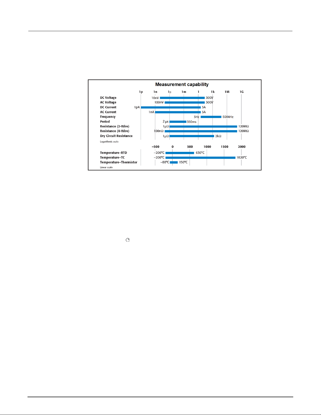
Section 1: Introduction Series 3700A System Switch/Multimeter Reference Manual
1-4 3700AS-901-01 Rev. D/June 2018
Measuring capabilities
The basic measurement capabilities of Series 3700A systems are summarized in the following figure.
Figure 1: DMM measurement capabilities
Displaying the instrument's serial number
The instrument serial number is on a label on the rear panel of the instrument. You can also access
the serial number from the front panel using the front-panel keys and menus.
To display the serial number on the front panel:
1. If the Series 3700A is in remote operation, press the EXIT (LOCAL) key once to place the
instrument in local operation.
2. Press the MENU key.
3. Use the navigation wheel to scroll to the UNIT-INFO menu item.
4. Press the ENTER key. The SYSTEM INFORMATION menu is displayed.
5. Scroll to the SERIAL# menu item.
6. Press the ENTER key. The Series 3700A serial number is displayed.
Page 26
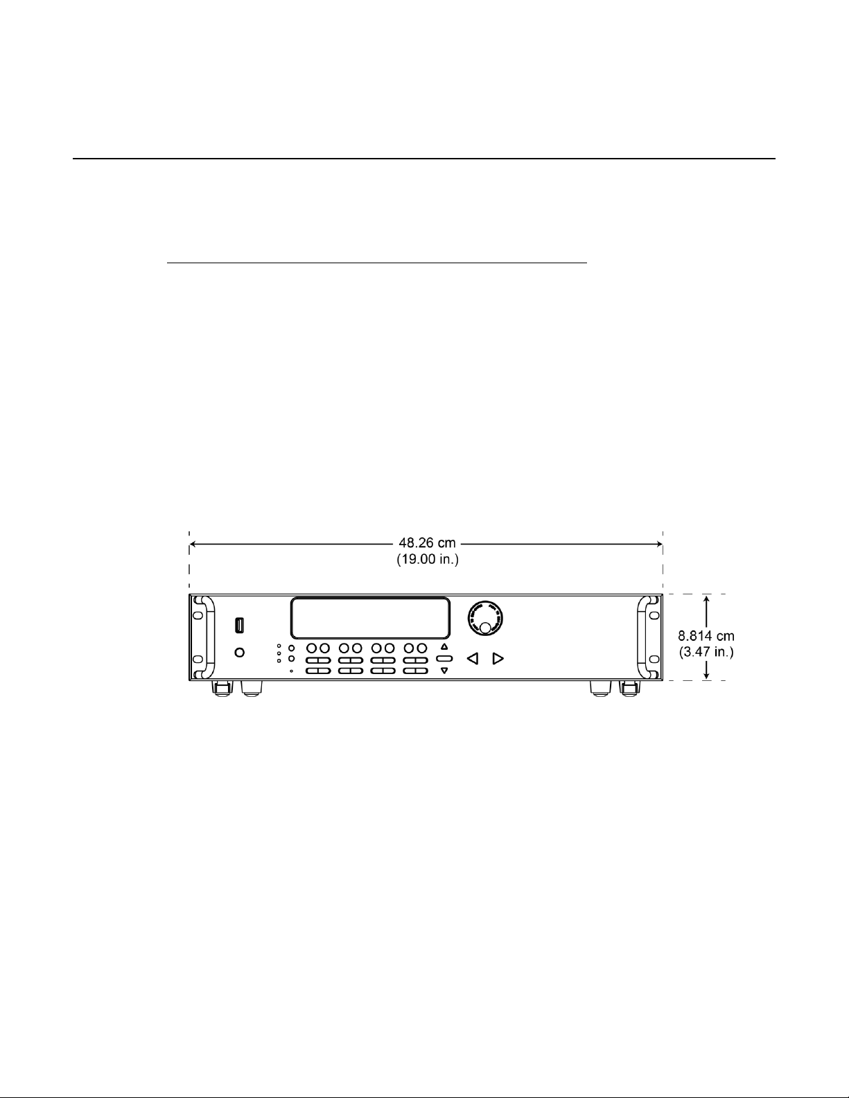
In this section:
Dimensions .............................................................................. 2-1
Weight ...................................................................................... 2-3
Rack-mounting instructions ...................................................... 2-3
Remote communications interfaces ......................................... 2-6
Digital I/O ............................................................................... 2-28
Starting up your instrument .................................................... 2-33
Dimensions
The following figures show the dimensions of the Series 3700A.
Figure 2: Model 3706A height and front-panel width
Section 2
Installation
Page 27

Section 2: Installation Series 3700A System Switch/Multimeter Reference Manual
2-2 3700AS-901-01 Rev. D/June 2018
Figure 3: Model 3706A depth and rear-panel width
Figure 4: Model 3706A dimensions for rear-support mounting with Model 4299-10
Page 28

Series 3700A System Switch/Multimeter Reference Manual Section 2: Installation
3700AS-901-01 Rev. D/June 2018 2-3
Weight
The weights of the Series 3700A, plug-in cards, and the screw terminal adapter are provided in the
following table.
Component
Weight
Model 3706A mainframe
6.12 kg (13.5 lb)
Plug-in card, average
1.36 kg (3 lb)
Screw terminal adapter, average
0.45 kg (1 lb)
You can calculate the total weight of your Series 3700A using the weights of the individual
components in your system. For example, if you have a Series 3700A mainframe with six plug-in
cards and three adapters installed:
6.12 kg + (1.36 kg 6) + (0.45 kg 3) = 15.63 kg
(13.5 lb + (3.0 lb 6) + (1.0 lb 3) = 34.45 lb)
Rack-mounting instructions
The following instructions are for configurations with up to two plug-in cards. If you have more than
two cards installed in the Series 3700A mainframe, you must use the optional Model 4288-10 Rear
Support Mount Kit in a fixed installation.
Tools required
• Medium (#2) Phillips-head screwdriver
Parts list
The table below lists the hardware that is supplied with the Series 3700A.
Item description
Part number
Quantity
Cage nut
FA-148
4
10-32 5/8 in. Phillips truss-head screw
n/a
4
Page 29
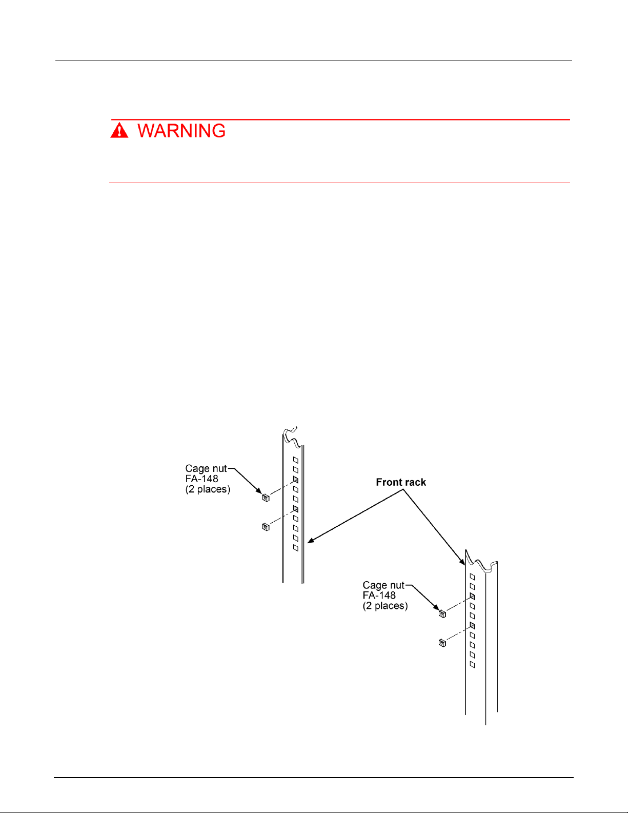
Section 2: Installation Series 3700A System Switch/Multimeter Reference Manual
2-4 3700AS-901-01 Rev. D/June 2018
Prepare the Series 3700A for rack-mount installation
Before installing the instrument, disconnect all external power from the equipment and
disconnect the line cord. Failure to disconnect all power may expose you to hazardous
voltages, which, if contacted, could cause personal injury or death.
To prepare the Series 3700A for mounting:
1. Verify that power is disconnected from the Series 3700A.
2. Place the instrument upside-down.
3. From the four foot assemblies on the bottom of the Series 3700A, remove the rubber centers.
4. Use a Phillips-head screwdriver to remove the four foot assemblies. Retain the rubber foot
assemblies for future use.
5. Place the instrument right-side up.
Prepare the rack for Series 3700A installation
To prepare the rack for installation of a Series 3700A mainframe with up to two plug-in cards:
1. If possible, remove the cabinet sides from the rack.
2. Select a location in the rack.
3. To make it easier to manipulate and install the Series 3700A, clear as much space as possible
around the location in the rack.
4. Install the four FA-148 cage nuts in the front rack rail holes.
Figure 5: Install the cage nuts in front rack rails
Page 30
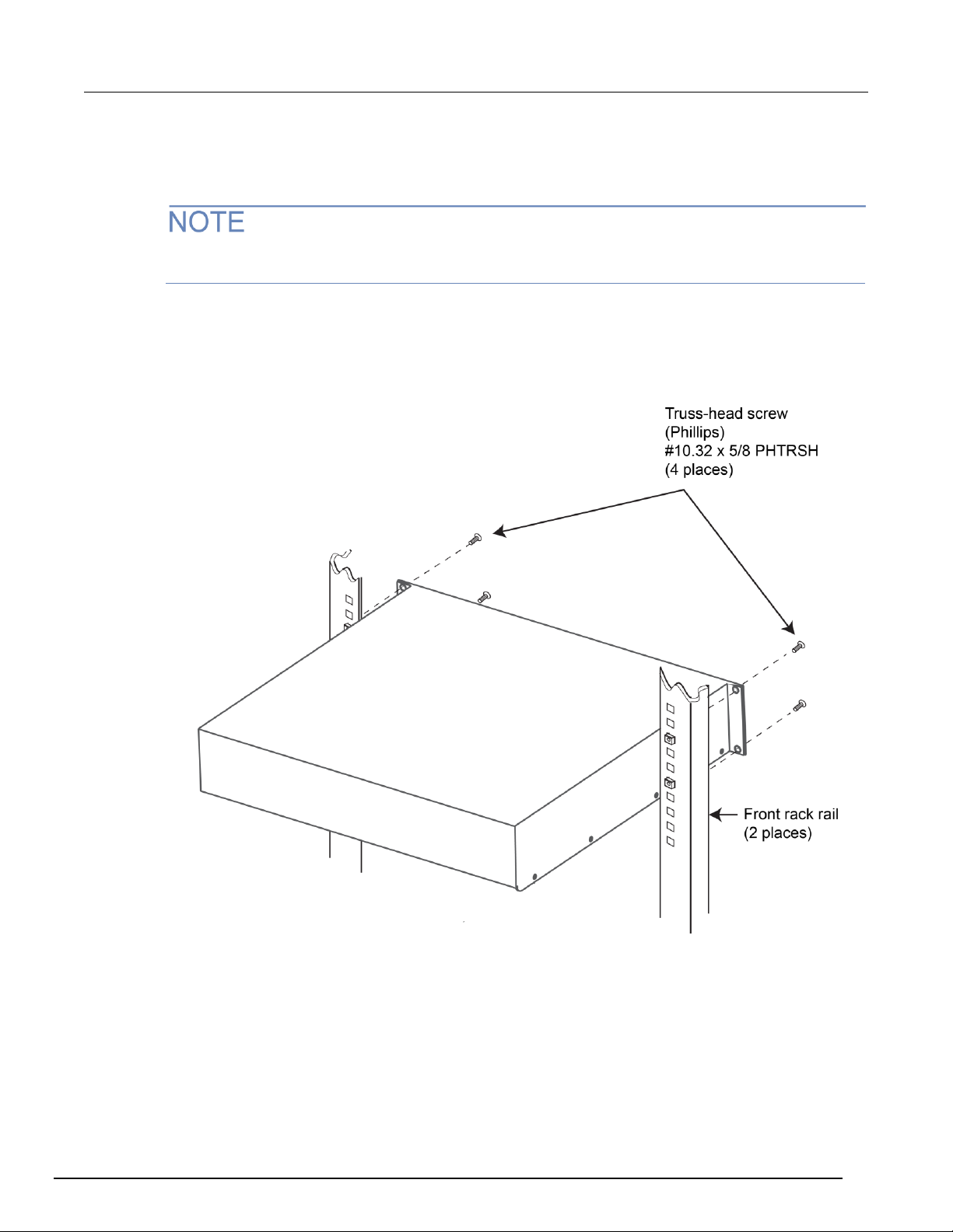
Series 3700A System Switch/Multimeter Reference Manual Section 2: Installation
3700AS-901-01 Rev. D/June 2018 2-5
Install the Series 3700A
To install the Series 3700A in the rack:
If the Series 3700A mainframe has more than two plug-in cards installed, you must use the optional
Model 4288-10 Rear Support Mount Kit in a fixed installation.
1. While supporting the Series 3700A, align the mounting holes on the front panel of the Series
3700A with the four cage nuts installed in the front rack rails.
2. Insert the four truss-head screws through the front-panel mounting holes into the cage nuts, and
tighten with a Phillips-head screwdriver.
Figure 6: Install the instrument in the rack
Page 31

Section 2: Installation Series 3700A System Switch/Multimeter Reference Manual
2-6 3700AS-901-01 Rev. D/June 2018
Remote communications interfaces
This section shows you how to connect instruments to the following remote communication
interfaces:
• Universal serial bus (USB)
• Local area network (LAN)
• General purpose interface bus (GPIB or IEEE-488)
The USB can be used for single ASCII-based commands.
This section describes how to configure and troubleshoot these interfaces on computers with
Microsoft® Windows® 2000, Windows XP, Windows Vista, and Windows 7 operating systems.
It also describes the I/O software, drivers, and application software that can be used with Keithley’s
instruments.
Supported remote interfaces
The Series 3700A supports the following remote interfaces:
• GPIB. General purpose interface bus is an IEEE-488 instrumentation data bus.
• LAN. Local area network (LAN) communications provide the flexibility to build scalable and
functional test or data acquisition systems with a large degree of flexibility.
• USB. Communicate with the instrument over a Type B USB connection.
The Series 3700A can be controlled from only one communication interface at a time. The first
interface from which it receives a message takes control of the instrument. It ignores the other
interfaces until the instrument is returned to local operation.
For more information about the remote interfaces, see:
• GPIB setup (on page 2-11)
• LAN concepts and settings (on page A-1)
• USB communications (on page 2-6)
USB communications
To use the rear-panel USB port, you must have the Virtual Instrument Software Architecture (VISA)
layer on the host computer. See How to install the Keithley I/O Layer for more information.
VISA contains a USB-class driver for the USB Test and Measurement Class (USBTMC) protocol that,
once installed, allows the Microsoft Windows operating system to recognize the instrument.
When you connect a USB device that implements the USBTMC or USBTMC-USB488 protocol to the
computer, the VISA driver automatically detects the device. Note that the VISA driver only
automatically recognizes USBTMC and USBTMC-USB488 devices. It does not recognize other USB
devices, such as printers, scanners, and storage devices.
In this section, "USB instruments" refers to devices that implement the USBTMC or
USBTMC-USB488 protocol.
Page 32

Series 3700A System Switch/Multimeter Reference Manual Section 2: Installation
3700AS-901-01 Rev. D/June 2018 2-7
Communicate with the instrument
To communicate with the USB device, you need to use NI-VISATM. VISA requires a resource string in
the following format to connect to the correct USB instrument:
USB[board]::manufacturer ID::model code::serial number[::USB interface
number][::INSTR]
This requires that you determine the parameters. You can gather this information by running a utility
that automatically detects all instruments connected to the computer.
If you installed the Keithley I/O Layer, the Keithley Configuration Panel is available from the
Microsoft® Windows® Start menu in the Keithley Instruments menu.
To use the Keithley Configuration Panel to determine the VISA resource string:
1. Start the Keithley Configuration Panel. The Select Operation dialog box is displayed.
2. Select Add.
Figure 7: Select Operation dialog box
3. Click Next. The Select Communication Bus dialog box is displayed.
Page 33

Section 2: Installation Series 3700A System Switch/Multimeter Reference Manual
2-8 3700AS-901-01 Rev. D/June 2018
Figure 8: Select Communication Bus dialog box
4. Select USB.
5. Click Next. The Select Instrument Driver dialog box is displayed.
Figure 9: Select Instrument Driver dialog box
Page 34

Series 3700A System Switch/Multimeter Reference Manual Section 2: Installation
3700AS-901-01 Rev. D/June 2018 2-9
6. Select Auto-detect Instrument Driver - Model.
7. Click Next. The Configure USB Instrument dialog box is displayed with the detected instrument
VISA resource string displayed.
Figure 10: Configure USB Instrument dialog box
8. Click Next. The Name Virtual Instrument dialog box is displayed.
Figure 11: Name Virtual Instrument dialog box
9. In the Name Virtual Instrument box, enter a name that you want to use to refer to the instrument.
10. Click Finish.
11. Click Cancel to close the Wizard.
Page 35

Section 2: Installation Series 3700A System Switch/Multimeter Reference Manual
2-10 3700AS-901-01 Rev. D/June 2018
12. Save the configuration. From the Configuration Utility, select File > Save.
13. In the Keithley Communicator, select File > Open Instrument to open the instrument you just
named.
Figure 12: Keithley Communicator Open an Instrument
14. Click OK.
15. Send a command to the instrument and see if it responds.
Figure 13: Send a command to the instrument
Page 36

Series 3700A System Switch/Multimeter Reference Manual Section 2: Installation
3700AS-901-01 Rev. D/June 2018 2-11
If you have a full version of NI VISA on your system, you can run NI-MAX or the VISA Interactive
Utility. See their documentation for information.
If you have the Keysight IO Libraries on your system, you can run Keysight Connection Expert to
check out your USB instruments. See their documentation for information.
Additional USB information
This section provides further details and more advanced information about the USB bus and
test-and-measurement instruments.
Connecting multiple USB instruments to the computer
The most convenient way to connect USB instrumentation to the computer is to plug a USB cable
directly from the instrument to the computer. If you have more than one USB instrument or have other
USB devices, such as printers, keyboards, and mice, you might not have enough USB connectors on
the computer.
To gain more ports, you can use a USB hub or add more USB controller cards if you have available
PCI or PCI Express slots.
The types of USB hubs that you can use with Series 3700A:
• Bus powered: This type of hub draws its power from the USB bus and can only supply 100 mA
(USB 2.0) per port.
• Self powered: This type of hub has an external power supply and can supply up to 500 mA per
port (USB 2.0).
GPIB setup
This section contains information about GPIB standards, connections, and address selection.
The GPIB connector is optional and may not be present on your instrument.
GPIB standards
The GPIB is the IEEE-488 instrumentation data bus, which uses hardware and programming
standards originally adopted by the Institute of Electrical and Electronic Engineers (IEEE) in 1975.
The instrument is IEEE Std 488.1 compliant and supports IEEE Std 488.2 common commands and
status model topology.
Install the GPIB driver software
Check the documentation for your GPIB controller for information about where to acquire drivers.
Keithley Instruments also recommends that you check the website of the GPIB controller for the latest
version of drivers or software.
It is important that you install the drivers before you connect the hardware. This prevents associating
the incorrect driver to the hardware.
Page 37

Section 2: Installation Series 3700A System Switch/Multimeter Reference Manual
2-12 3700AS-901-01 Rev. D/June 2018
Install the GPIB cards in your computer
Refer to the documentation from the GPIB controller vendor for information about installing the GPIB
controllers.
Set the GPIB address
The GPIB address is set to 16 at the factory. The address can be set to any address value from 0 to
30. However, the address must be unique in the system. It cannot conflict with an address that is
assigned to another instrument or to the GPIB controller.
To change the GPIB address:
1. Press the MENU key.
2. Select GPIB > ADDRESS. Press the navigation wheel to display the current address.
3. Choose the appropriate GPIB address.
4. Press ENTER to save the address.
The address value is saved in nonvolatile memory and will not change when a reset() (on page 11-
308) command is sent or when the power is turned off and then turned on again.
When the GPIB bus is operating, you can use the gpib.address (on page 11-252) attribute to change
the GPIB address remotely.
Enable GPIB
By default, the instrument is set to GPIB enabled. You only need to enable it if GPIB control was
disabled.
To enable control through the GPIB:
1. Press the MENU key.
2. Select GPIB. Press the navigation wheel to display the GPIB MENU.
3. Select ENABLE. Press the navigation wheel .
4. To enable GPIB, select ON. To disable it, select OFF.
5. Press ENTER to save the setting.
You must turn the instrument on and off before the setting takes effect.
Communicate with instruments
The GPIB driver software you installed installs an interactive dumb terminal program that allows you
to send commands to the instrument. They directly call the GPIB driver support libraries.
For the KPCI-488LPA and KUSB-488B GPIB controller from Keithley Instruments, the configuration
utility is called the KI-488 Diagnostic Tool. It is available from the Windows Start menu at Keithley
Instruments > KI-488 > KI-488 Diagnostic Tool.
For the KUSB-488A GPIB controller from Keithley Instruments, the configuration utility is called
TrTest. It is available from the Windows Start Menu at Keithley Instruments > GPIB-488-CEC >
TrTest.
For National Instruments GPIB controllers, you can use NI-MAX. Start NI-MAX. If your hardware is
installed correctly, you should see the controller in the GPIB section of the tree control on the left
side. Select it and right-click to see an option to communicate with the instrument.
Page 38

Series 3700A System Switch/Multimeter Reference Manual Section 2: Installation
3700AS-901-01 Rev. D/June 2018 2-13
If you want to use the GPIB controller with instrument driver (such as VXIPnP or IVI) or high-level
software, you must also install I/O software, which installs the VISA layer. See How to install the
Keithley I/O Layer.
Terminator
When receiving data over the GPIB, the instrument terminates messages on any line feed character
or any data byte with EOI asserted (line feed with EOI asserted is also valid). When sending data, it
appends a line feed character to all outgoing messages. The EOI line is asserted with the terminating
line feed character.
However, if you want your program to communicate with all I/O buses on the instrument (GPIB, USB,
LAN (VXI-11 and raw socket)), it is good practice to add a line feed to the end of the outgoing
command. Use VISA and the same program will work with all the I/O buses by changing the resource
string in the VISA Open method.
Front-panel GPIB operation
This section describes aspects of the front panel that are part of GPIB operation, including messages,
status indicators, and the LOCAL key.
Error and status messages
The front-panel display may show error and status messages. See Error summary list (on page 12-9)
for a list of status and error messages that are associated with IEEE-488 programming.
LOCAL key
The EXIT (LOCAL) key cancels the remote state and restores local operation of the instrument.
Pressing the EXIT (LOCAL) key also turns off the REM indicator and returns the display to normal if a
user-defined message was displayed.
If the LLO (Local Lockout) command is in effect, the EXIT (LOCAL) key is also inoperative. Note that
pressing the EXIT (LOCAL) key will also abort any commands or scripts that are being processed.
GPIB reference
General bus commands
General commands are commands that have the same general meaning, regardless of the
instrument (for example, DCL). The following table lists the general bus commands.
General bus commands
Command
Effect on Series 3700A
REN
Goes into remote operation when next addressed to listen. See REN (on page 2-14) for
details.
IFC
Goes into talker and listener idle states. See IFC (on page 2-14) for details.
LLO
LOCAL key locked out. See LLO (on page 2-14) for details.
GTL
Cancel remote; restore Series 3700A front-panel operation. See GTL (on page 2-14) for
details.
DCL
Returns the Series 3700A and all devices on the GPIB to known conditions. See DCL
(on page 2-14) for details.
SDC
Returns the Series 3700A to known conditions. See SDC (on page 2-14) for details.
GET
Initiates a trigger. See GET (on page 2-15) for details.
SPE, SPD
Serial polls the Series 3700A. See SPE, SPD (on page 2-15) for details.
Page 39

Section 2: Installation Series 3700A System Switch/Multimeter Reference Manual
2-14 3700AS-901-01 Rev. D/June 2018
REN
The remote enable (REN) command is sent to the Series 3700A by the controller to set up the
instrument for remote operation. Generally, the instrument should be placed in the remote mode
before you attempt to program it over the bus. Setting REN true does not place the instrument in the
remote state. You must address the instrument to listen after setting REN true before it goes into
remote operation.
IFC
The interface clear (IFC) command is sent by the controller to place the Series 3700A in the talker
idle state and the listener idle state. The instrument responds to the IFC command by canceling frontpanel TALK or LSTN lights, if the instrument was previously placed in one of these states.
Transfer of command messages to the instrument and transfer of response messages from the
instrument are not interrupted by IFC. If transfer of a response message from the instrument was
suspended by IFC, transfer of the message will resume when the instrument is addressed to talk. If
transfer of a command message to the instrument was suspended by IFC, the rest of the message
can be sent when the instrument is addressed to listen.
LLO
When the instrument is in remote operation, all front-panel controls are disabled, except the LOCAL
and OUTPUT OFF keys (and the POWER switch). The local lockout (LLO) command disables the
LOCAL key, but does not affect the OUTPUT OFF switch, which cannot be disabled.
GTL
Use the go to local (GTL) command to put a remote-mode instrument into local mode. Leaving the
remote state also restores operation of all front-panel controls.
DCL
Use the device clear (DCL) command to clear the GPIB interface and return it to a known state. Note
that the DCL command is not an addressed command, so all instruments equipped to implement DCL
will do so simultaneously.
When the Series 3700A receives a DCL command, it:
• Clears the input buffer, output queue, and command queue
• Cancels deferred commands
• Clears any command that prevents the processing of any other device command
A DCL does not affect instrument settings and stored data.
SDC
The selective device clear (SDC) command is an addressed command that performs essentially the
same function as the device clear (DCL) command. However, because each device must be
individually addressed, the SDC command provides a method to clear only selected instruments,
instead of clearing all instruments simultaneously with the DCL command.
When the Series 3700A receives an SDC command, it:
• Clears the input buffer, output queue, and command queue
• Cancels deferred commands
• Clears any command that prevents the processing of any other device command
An SDC does not affect instrument settings and stored data.
Page 40

Series 3700A System Switch/Multimeter Reference Manual Section 2: Installation
3700AS-901-01 Rev. D/June 2018 2-15
GET
The group execute trigger (GET) command is a GPIB trigger that triggers the instrument to take
readings from a remote interface.
SPE, SPD
Use the serial polling sequence to obtain the Series 3700A serial poll byte. The serial poll byte
contains important information about internal functions (see Status Byte Register overview (on page
C-3)). Generally, the serial polling sequence is used by the controller to determine which of several
instruments has requested service with the SRQ line. The serial polling sequence may be performed
at any time to obtain the status byte from the Series 3700A.
Configure the GPIB controllers
Each instrument on a GPIB bus needs a unique address from a range of 0 to 30. Generally, the GPIB
host controller is on address 0. However, there are GPIB controllers that adopt the address of 21. To
be safe, do not configure any of the instruments for 21 or 0.
If you do need to change the host controller address, consult the controller documentation.
For the KPCI-488LPA and KUSB-488B GPIB controller from Keithley Instruments, the configuration
utility is called the KI-488 Diagnostic Tool. It is available from the Microsoft® Windows® Start menu at
Keithley Instruments > KI-488 > KI-488 Diagnostic Tool.
For the KUSB-488A GPIB controller from Keithley Instruments, the configuration utility is called GPIB
Configuration. It is available from the Windows Start Menu at Keithley Instruments > GPIB-488 >
GPIB Configuration.
For National Instruments (NITM) GPIB controllers, you can use NI-MAX. Start NI-MAX. If your
hardware is installed correctly, you will see the controller in the GPIB section of the tree control on the
left side. Select it and right-click to see an option to configure the controller. Do not forget to save
your settings.
Communication status indicators
The remote (REM), talk (TALK), listen (LSTN), and service request (SRQ) indicators show the
communication bus status. Each of these indicators is described below.
Status indicator
Applies to
REM
GPIB, VXI-11, USB
TALK
GPIB only
LSTN
GPIB only
SRQ
GPIB, VXI-11, USB
The SRQ applies to all available communication buses, however, actual service requests only apply
to GPIB, USB, and VXI-11 (see Status byte and service request (SRQ) (on page C-15) for more
information).
REM
This indicator is illuminated when the instrument is in the remote control state. When the instrument is
in the remote control state, all front-panel keys, except for the EXIT (LOCAL) key, are locked out.
When REM is off, the instrument is in the local control state and front-panel operation is restored.
Page 41

Section 2: Installation Series 3700A System Switch/Multimeter Reference Manual
2-16 3700AS-901-01 Rev. D/June 2018
TALK
This indicator is on when the instrument is in the talker active state. Place the instrument in the talk
state by addressing it to talk with the correct talk command. TALK is off when the instrument is in the
talker idle state. Place the instrument in the talker idle state by sending a UNT (untalk) command,
addressing it to listen, or by sending the IFC (interface clear) command.
LSTN
This indicator is on when the instrument is in the listener active state, which is activated by
addressing the instrument to listen with the correct listen command. LSTN is off when the instrument
is in the listener idle state. Place the instrument in the listener idle state by sending UNL (unlisten),
addressing it to talk, or by sending the IFC (interface clear) command over the bus.
SRQ
You can program the instrument to generate a service request (SRQ) when one or more errors or
conditions occur. When this indicator is on, a service request has been generated. This indicator
stays on until all conditions that caused the SRQ are cleared.
Note that while the SRQ indicator turns on when a service request is generated, it reflects the state of
the Master Summary Status (MSS) bit and not the request for service (RQS) bit (see "Bit 6, Request
Service (RQS)/Master Summary Status (MSS)" in the topic Status Byte Register (on page C-16) for
more detail). Therefore, performing a serial poll will not turn off the indicator. In order to turn off the
indicator, you must clear all the conditions that caused the MSS bit to be set. Refer to Clearing
registers (on page C-13) for information.
LAN communications
This section provides an overview of LAN communications for the Series 3700A. For detailed
information about setting up your LAN interface, refer to LAN concepts and settings (on page A-1).
You can communicate with the instrument using a local area network (LAN).
When you connect using a LAN, you can use a web browser to communicate with the instrument
through the instrument's internal web page and other web applets.
Series 3700A are class B and C LXI version 1.4 compliant. They are scalable test instruments with
direct connections to host computers. They can also interact with a DHCP or DNS server and other
LXI compliant instruments on a LAN.
The Series 3700A are compliant with IEEE standard 802.3 (ethernet) and support full connectivity on
a 10 Mbps or 100 Mbps network.
Contact your network administrator to confirm your specific network requirements before setting up a
LAN connection.
Page 42

Series 3700A System Switch/Multimeter Reference Manual Section 2: Installation
3700AS-901-01 Rev. D/June 2018 2-17
Overview of LAN instruments
When ethernet ports became standard on computers, it was logical that instrumentation would follow.
The VXI-11 protocol, which was standardized on in the early 1990s, is the standard used to emulate
GPIB over ethernet.
Even though ethernet became the standard LAN technology on instruments, LAN instruments from
different vendors differed in the approach they took. Some vendors only supported static IP, whereas
others had DHCP, DLLA (Auto-IP), and static addressing. The LXI consortium was started to
standardize what should be in all instruments that conform to LXI.
An instrument that conforms to LXI version 1.3 must have the following:
• All three IP addressing modes: DHCP, Auto-IP, and static IP.
• A web server that has some standard ethernet configuration parameters:
▪ IP configuration: IP address, subnet mask, gateway.
▪ Password protection on anything that might change the instrument state.
▪ A control on the web page that flashes an LED or some form of indicator on the front panel of
the instrument. LXI calls this the Device Identification Functionality. This allows you to identify
the web page you are currently looking at with the instrument. This helps you identify a
specific instrument in a rack of similar model instruments.
• A reserved URL in the instrument that provides an xml document that has standard configuration
information. This can be useful for software tools that need to identify the instruments and their
capabilities. The URL is http://<host>:<port>/lxi/identification.
• An IVI driver for the instrument.
• A LAN Status (fault) indicator.
• VXI-11 discovery protocol.
• LAN reset button or menu option. LXI calls this the LAN Configuration Initialize (LCI).
When the LXI-defined LAN reset is selected, the instrument reverts its LAN settings to a known
set of defaults. The default LAN settings for LXI instruments are:
▪ DHCP and Auto-IP enabled. LXI refers to this as the Auto IP address mode (compared to the
manual address mode, which is fixed or static IP addressing).
▪ Web password is reset to the factory default.
▪ Ping responder enabled.
▪ Dynamic DNS and mDNS enabled.
LXI Version 1.3 added the requirement of mDNS (multicast DNS) discovery.
Page 43

Section 2: Installation Series 3700A System Switch/Multimeter Reference Manual
2-18 3700AS-901-01 Rev. D/June 2018
LAN cable connection
The Series 3700A includes two LAN crossover cables. One cable is for the TSP-Link® network and
the other cable is for LAN communications.
Use the following figure as a guide when making LAN connections.
Figure 14: Series 3700A LAN connection
1. Series 3700A ethernet port (LAN)
2. Straight-through LAN cable or crossover LAN cable
3. Ethernet port (located on the host computer)
Supplied software
The majority of software applications and all instrument drivers from Keithley Instruments depend on
some, or all, of the following software components:
• NI-VISATM
• VISA shared components
• IVI shared components
• NITM CVITM runtime engine
• NITM IVITM compliance package
• Keithley instrument driver
• LabVIEWTM driver
• Test Script Builder (TSB) Add-in
• J2SETM Runtime Environment
These software components are available for download from the Product Support web page
(https://www.tek.com/product-support).
Page 44

Series 3700A System Switch/Multimeter Reference Manual Section 2: Installation
3700AS-901-01 Rev. D/June 2018 2-19
Instrument driver types
There are several different styles of instrument drivers. Keithley Instruments provides three different
instrument drivers for the Series 3700A: A native LabVIEW driver, an IVI-C driver, and an IVI-COM
driver. You need to pick the style that best suits the application development environment (ADE) that
you are using. For example, if you are using LabVIEW, you would pick a native LabVIEW driver. If a
native LabVIEW driver is not available then you can use an IVI-C driver as LabVIEW has the option of
creating a wrapper for the IVI-C driver.
LabVIEW supports IVI-COM drivers but they are definitely not the first or second choice. However, if
they are the only driver types for the instrument, they can be used.
If LabWindows/CVI or C/C++ is your programming language, an IVI-C driver is the best option. For
Microsoft® Visual Basic® 6.0 and any .NET language (C#, VB.NET, and so on), an IVI-COM driver is
the best option.
Sometimes instrument vendors do not provide all three driver types. Most languages can
accommodate other driver types, but this is not optimal.
The following sections describe the different driver types in more detail.
VXIPnP drivers
VXI (Vixie) plug-and-play (VXIPnP) style drivers are Win32 DLLs that have some standard functions
defined by the VXIPnP Alliance, such as:
• init
• close
• error_message
• reset
• self_test
• Read
• Initiate
• Fetch
• Abort
The application programming interface (API) was defined so that users of instruments would have a
familiar API from instrument to instrument. There are some basic guidelines when creating APIs for
your instrument, such as using VISA data types and how to construct the CVI hierarchy.
Page 45

Section 2: Installation Series 3700A System Switch/Multimeter Reference Manual
2-20 3700AS-901-01 Rev. D/June 2018
LabVIEW drivers
Native LabVIEW drivers
A native LabVIEWTM driver is a LabVIEW driver that is created using entirely built-in LabVIEW VIs —
it does not make any calls to external DLLs or Library files. This makes the driver portable to all the
platforms and operating systems that LabVIEW and VISA supports (currently, Linux® on x86, Mac
OS® X, and Microsoft® Windows®).
National Instruments (NITM) maintains a native LabVIEW driver style guide
(http://zone.ni.com/devzone/cda/tut/p/id/3271).
LabVIEW driver wrappers
All IVI-C drivers have a function panel file (.fp) that shows a hierarchy of the function calls into a DLL.
It is a tool that guides a user to select the correct function call in the driver, since a DLL only has a flat
API entry point scheme (unlike COM or .NET). Any CVI-generated .fp file can be imported into
LabVIEW and LabVIEW will generate a wrapper for the DLL. The drawback here is that the driver is
dependent on the DLL, which is not portable and is therefore Windows-specific.
Getting instrument drivers
To see what drivers are available for your instrument:
1. Go to the Product Support web page (https://www.tek.com/product-support).
2. Enter the model number of your instrument.
3. Select Software from the list.
4. Select and download the file.
For LabVIEWTM, you can also go to the National Instruments website and search their instrument
driver database.
Instrument driver examples
All Keithley drivers come with examples written in several programming languages that show you how
to do the most common things with the instruments.
The examples are in the Microsoft® Windows® Start menu, under Keithley Instruments > Model
Number (where Model Number is the instrument model number).
IVI shared components
The IVI shared components are a similar concept to the VISA shared components. The IVI
Foundation provides class drivers for:
• All the supported instruments (DMM, Scope, Fgen, and so on)
• The configuration store
The IVI shared components also create the installation folders and registry keys that all IVI drivers
and support files use for installation.
Page 46

Series 3700A System Switch/Multimeter Reference Manual Section 2: Installation
3700AS-901-01 Rev. D/June 2018 2-21
Interchangeable Virtual Instruments (IVI) style drivers
The major problem with VXIPnP drivers was that the API was not specific to the instrument. For
something as standard as measuring DC volts on a digital multimeter (DMM), it would be a good idea
if there were a set of standard functions to do this.
The IVI Foundation (http://www.ivifoundation.org) defined a set of application programming interfaces
(APIs) for the following instruments: DMM, function generator, DC power supply, scope, switch,
spectrum analyzer, RF signal generator and power meter. They are currently working on class APIs
for some other instrument types.
There are two types of IVI drivers: IVI-COM drivers use Microsoft® COM technology to expose driver
functionality, while IVI-C drivers use conventional Microsoft® Windows® DLLs to export simple Cbased functions.
For more information about IVI drivers and the differences between the COM, C, and .NET interfaces,
see Understanding the Benefits of IVI
(http://www.ivifoundation.org/docs/Understanding%20the%20Benefits%20of%20IVI[3].pdf).
NI CVI runtime engine
IVI-C drivers that are created using National Instruments (NITM) LabWindows/CVI environment
depend on either the CVI runtime (cvirte.dll), or the instrument support run-time (instrsup.dll), and
must be present on the system for them to run.
NI IVI Compliance Package
The National Instruments (NITM) IVI Compliance Package is a software package that contains IVI
class drivers and support libraries that are needed for the development and use of applications that
leverage IVI instrument interchangeability. The IVI Compliance Package also is based on and is
compliant with the latest version of the instrument programming specifications defined by the IVI
Foundation.
The NI ICP installer installs the IVI shared components, CVI runtime engine, and the instrument
support runtime engine.
Keithley I/O layer
The Keithley I/O Layer (KIOL) is a software package that contains several utilities and drivers. It is
mainly used as a supplement to IVI drivers or application software like Test Script Builder (TSB).
The KIOL contains:
• NI-VISATM Runtime-Time Engine
• Keithley Configuration Panel
• Keithley Communicator
For additional detail on the Keithley I/O layer, including computer requirements, see the
tek.com/keithley website.
Page 47

Section 2: Installation Series 3700A System Switch/Multimeter Reference Manual
2-22 3700AS-901-01 Rev. D/June 2018
NI-VISA Runtime
NI-VISATM is National Instruments (NITM) implementation of the VISA standard. There are two
versions. The full version contains diagnostic and configuration tools such as NI-Spy and NI-MAX and
the binary run-time-only files. The run-time version contains only the binary files (DLLs) that allow the
drivers to operate.
The Keithley I/O Layer (KIOL) contains a licensed version of the NI-VISA runtime.
If you already have NI software (such as LabVIEW or LabWindows) installed, you have a valid license
that can be used with Keithley drivers and application software.
If you do not have NI software installed, to use Keithley drivers or application software, you must
install the KIOL. This installs a valid, licensed copy of the NI-VISA runtime to use with Keithley drivers
or application software. KIOL installs a valid license for the NI-VISA Run-Time Engine only (not the
full version of NI-VISA).
Keithley Configuration Panel
The Keithley Configuration Panel is a configuration utility for IVI drivers, similar to NI-MAX. It can also
autodetect USBTMC instruments and LAN instruments that support the VXI-11 protocol.
Keithley Communicator
The Keithley Communicator is a dumb terminal program that uses VISA to communicate with the
instrument.
How to uninstall previous versions of the Keithley I/O Layer
If you have an earlier version of the Keithley I/O Layer software installed on your computer, you must
uninstall it.
To uninstall the Keithley I/O layer:
1. From the Control Panel, select Add/Remove Programs.
2. Uninstall the following components:
▪ Keithley I/O Layer
▪ Keithley I/O Layer Suite
▪ Keithley SCPI-based Instrument IVI-C Driver
▪ NI-VISA Run-Time Engine x.x.x (if present) (x.x.x is the VISA version)
3. Reboot your computer.
How to install the Keithley I/O Layer
You can download and install the Keithley I/O Layer from the Product Support web page
(https://www.tek.com/product-support).
The software installs the following components:
• Microsoft® .NET Framework
• NITM IVI Compliance Package
• NI-VISATM Run-Time Engine
• Keithley SCPI-based Instrument IVI-C driver
• Keithley I/O Layer
Page 48

Series 3700A System Switch/Multimeter Reference Manual Section 2: Installation
3700AS-901-01 Rev. D/June 2018 2-23
To install the Keithley I/O Layer from the Keithley website:
1. Download the Keithley I/O Layer Software. The software is a single compressed file and should
be downloaded to a temporary directory.
2. Run the downloaded file from the temporary directory.
3. Follow the instructions on the screen to install the software.
4. Reboot your computer to complete the installation.
Special installation considerations
Situations may occur during installation that cannot be handled automatically by the installation utility.
The installation utility will warn you if one of these situations is detected. The sections below describe
the action you must take before the installation can be completed.
Mismatch between IVI Shared Components and IVI Engine Detected
The IVI Shared Components and IVI Engine are software components that may be installed by
various test and measurement software applications, instrument drivers, and so on. Keithley I/O
Layer software requires that these components, if present, be compatible versions. The installation
utility will detect a mismatch, which must be corrected before the software installation can proceed. If
this situation is detected, the Keithley I/O Layer software installation will automatically stop.
The recommended way to resolve this situation is to install the IVI Compliance Package (ICP)
software from National Instruments (NITM). You may download the ICP software and release notes
from National Instrument’s website. When the ICP installation is complete, restart the Keithley I/O
Layer software installation.
Non-National Instruments VISA detected
VISA software is used to communicate with the instrument and may be installed by various test and
measurement software applications, instrument drivers, and so on. Keithley I/O Layer software
requires and will install National Instruments NI-VISATM software. The installer will detect if another
vendor’s version of VISA is already installed on the computer. If this occurs, the installer will pause
and display a warning message. The warning message displays the vendor of the detected VISA in
its title bar, if this can be determined. Make a note of the vendor name. At this point, you may elect to
continue the installation, which will overwrite the existing VISA installation with NI-VISA. This will
allow the Keithley I/O Layer software to operate properly, but may cause other applications or
instrument drivers that were dependent on the existing VISA to malfunction.
The recommended way to resolve this situation is to perform the following steps:
1. Exit the Keithley I/O Layer software when the warning message is displayed. Make note of the
VISA vendor in the warning message (if any).
2. Uninstall the non-NI VISA software.
3. Uninstall Tektronix VISA by selecting OpenChoice TekVISA from the Control Panel Add/Remove
programs list.
4. Uninstall Keysight VISA by selecting Keysight I/O Libraries Suite from the Control Panel
Add/Remove programs wizard list.
5. Uninstall other versions of VISA by selecting the appropriate entry from the Control Panel
Add/Remove Programs Wizard list.
6. Restart the Keithley I/O Layer software installation.
Page 49

Section 2: Installation Series 3700A System Switch/Multimeter Reference Manual
2-24 3700AS-901-01 Rev. D/June 2018
7. If the pre-existing version of VISA was supplied by Tektronix or Keysight (as displayed in the
warning message), you may safely reinstall that version of VISA once Keithley I/O Layer software
installation is complete. When you reinstall Tektronix or Keysight VISA, it may prompt you to
preserve the current VISA version, which you should do. This will usually restore the operation of
any dependent applications or drivers.
8. If the pre-existing version of VISA was supplied by a vendor other than Tektronix or Keysight, we
recommend that you do not reinstall it, because this will likely cause the Keithley I/O Layer
software to malfunction.
Installation troubleshooting
If problems occur during installation, it might be helpful to install the components individually. Errors
messages might appear that will help you resolve the installation issue.
If problems occur during installation:
1. Follow the instructions to uninstall all the KIOL components in Special installation considerations
(on page 2-23).
2. Rerun the KIOL installer. Note where the installer unpacks the files (usually in a temporary
folder).
3. Cancel the installer.
4. Go to the folder where the files were unzipped.
5. Run the setup.exe for each of the following components in the following order:
▪ IVI Compliance Package (ICP)
▪ NI-VISATM Run-Time Engine
▪ KIOL
▪ Keithley SCPI Driver
6. Ignore all the other folders.
7. Reboot the computer.
Modifying, repairing, or removing Keithley I/O Layer software
The Keithley I/O Layer interconnects many other installers.
To remove all the KIOL components, you need to uninstall the following applications using Control
Panel Add/Remove programs:
• National Instruments NITM IVI Compliance Package
• National Instruments NI-VISATM Run-Time Engine
• IVI Shared Components
• Visa Shared Components
• Keithley SCPI Driver
After uninstalling components, reboot the computer.
Page 50

Series 3700A System Switch/Multimeter Reference Manual Section 2: Installation
3700AS-901-01 Rev. D/June 2018 2-25
Addressing instruments with VISA
VISA allows you to communicate with the instrument on different communication buses by changing a
resource string that gets passed in with the viOpen function, in VISA-C, or with the Open method on
the VISA-COM resource manager object.
For detailed information about the format of the resource string, refer to the VISA specification
VPP4.3 at the IVI Foundation website, or refer to the help file provided by the vendor of the VISA
implementation you are using.
The following sections describe the resource strings for some of the communication types that
Keithley supports. Any field that has [] (square brackets) around it is optional and will revert to a
default value.
Addressing instruments through the LAN
VISA supports two different LAN protocols, each of which has a different resource string.
VXI-11 is a protocol that emulates GPIB over the LAN. Series 3700A supports this protocol. The
resource string is:
TCPIP[board]::host address[::LAN device name][::INSTR]
board is the network interface card in the computer. This value is usually skipped and VISA
determines the correct network interface card (if you have more than one) by looking at the IP
address.
host address can be either a valid DNS hostname, mDNS hostname, or the IPv4 IP (only) address
of the instrument.
LAN device name is a method of addressing secondary instruments at the main IP address, similar
to secondary addressing on the GPIB bus. The default is inst0.
A raw socket connection requires more work by the driver or application program to make sure the
correct amount of data has been sent or received correctly. All Keithley instruments support the raw
socket connection.
TCPIP[board]::host address::port::SOCKET
The board and the host address are the same as for the VXI-11 protocol.
port is the port to which to connect on the instrument. For the Series 3700A, the port is 5025.
Addressing instruments using USB
USB[board]::manufacturer ID::model code::serial number[::USB interface
number][::INSTR]
board is not used (0).
manufacturer ID is the USB.org reserved four-digit hexadecimal code for the instrument vendor
company. Keithley Instruments hexadecimal code is 0X5E6.
model code is the model number of the instrument. For example, when addressing a Model 3706A,
use 0X3706.
serial number is the serial number of the instrument.
USB interface number identifies which USBTMC interface on the instrument to address
(usually 0).
Page 51

Section 2: Installation Series 3700A System Switch/Multimeter Reference Manual
2-26 3700AS-901-01 Rev. D/June 2018
Addressing instruments through GPIB
There are two different resource classes in VISA for the GPIB bus.
INSTR is the basic class that everyone uses. It allows application software to send and receive data
and commands without dealing with some low level GPIB nuances. This class is recommended for
typical GPIB communication.
The INTFC class allows finer control over the GPIB controller card in the computer. You must comply
with the IEEE-488.1 protocol and tell the instrument to listen and the controller to talk before sending
a message to the instrument. This class allows you to communicate to the instrument using low-level
GPIB commands. Refer to your VISA documentation for more details on how to use this class.
The GPIB INSTR resource class format is:
GPIB[board]::primary address[::secondary address][::INSTR]
board is the number of the GPIB card, if there is more than one in the computer. If there is only one
GPIB card, do not include board, but do not leave a space.
primary address is the main GPIB address of the instrument, which can be changed, if
necessary, through the front panel of the instrument.
secondary address is for secondary addressing in GPIB. Some instruments have subinstruments
or cards inside the main instrument or backplane. The primary address identifies the main instrument.
The secondary address identifies subinstruments. Refer to the instrument user manual for the
secondary address, if applicable.
Sending raw commands to an instrument
The next sections show you how to use VISA-C and VISA-COM to send raw instrument commands
without using the instrument drivers.
VISA-C sample code
The following is a simple C/C++ console application that reads back the instrument identification
string using VISA-C. You need to include visa.h and link with the visa32.lib file.
#include "stdafx.h"
#include <visa.h>
#define checkErr(fCall) if (error = (fCall), (error = (error <
0) ? error : VI_SUCCESS)) \
{goto Error;} else error = error
int _tmain(int argc, _TCHAR* argv[])
{
ViSession defaultRM, vi;
char buf [256] = {0};
ViStatus error = VI_SUCCESS;
/* Open session to GPIB device at address 22 */
checkErr(viOpenDefaultRM(&defaultRM));
checkErr(viOpen(defaultRM, "GPIB0::14::INSTR", VI_NULL,VI_NULL, &vi));
/* Initialize device */
checkErr(viPrintf(vi, "*RST\n"));
Page 52

Series 3700A System Switch/Multimeter Reference Manual Section 2: Installation
3700AS-901-01 Rev. D/June 2018 2-27
/* Send an *IDN? string to the device */
checkErr(viPrintf(vi, "*IDN?\n"));
ViUInt16 status = 0;
do
{
checkErr(viReadSTB(vi, &status));
printf("ReadSTB = %X\n", status);
} while(status == 0);
/* Read results */
checkErr(viScanf(vi, "%t", &buf));
/* Print results */
printf ("Instrument identification string: %s\n", buf);
/* Close session */
checkErr(viClose(vi));
checkErr(viClose(defaultRM));
Error:
if(error < VI_SUCCESS)
printf("Visa Error Code: %X\n", error);
printf("\nDone - Press Enter to Exit");
getchar();
return 0;
}
Page 53

Section 2: Installation Series 3700A System Switch/Multimeter Reference Manual
2-28 3700AS-901-01 Rev. D/June 2018
VISA-COM sample code
This example gets the instrument identification string using VISA-COM in C#.
The first thing to do is add a reference to the VISA-COM interop DLL, which is usually located at
C:\Program Files\IVI Foundation\VISA\VisaCom\Primary Interop Assemblies\Ivi.Visa.Interop.dll.
using Ivi.Visa.Interop;
namespace WindowsApplication1
{
public class IdnSample: System.Windows.Forms.Form
{
private Ivi.Visa.Interop.FormattedIO488 ioDmm;
//
}
}
private void IdnSample_Load(object sender, System.EventArgs e)
{
ioDmm = new FormattedIO488Class();
SetAccessForClosed();
}
private void btnInitIO_Click(object sender, System.EventArgs e)
{
try
{
ResourceManager grm = new ResourceManager();
ioDmm.IO = (IMessage)grm.Open("GPIB::16::INSTR",
AccessMode.NO_LOCK, 2000, "");
ioDmm.IO.TerminationCharacterEnabled = true;
}
catch (SystemException ex)
{
MessageBox.Show("Open failed on " + this.txtAddress.Text + " " +
ex.Source + " " + ex.Message, "IdnSample", MessageBoxButtons.OK,
MessageBoxIcon.Error);
ioDmm.IO = null;
}
}
Digital I/O
The Series 3700A has a digital input/output port that can be used to control external digital circuitry.
For example, you can use a handler that is used to perform binning operations with a digital I/O port.
Page 54

Series 3700A System Switch/Multimeter Reference Manual Section 2: Installation
3700AS-901-01 Rev. D/June 2018 2-29
Port configuration
The digital I/O port, a standard female DB-25 connector (shown below), is on the rear panel.
Figure 15: Digital I/O port
Pin
Description
1
...
9
Digital I/O #1
...
Digital I/O #9
10
...
14
Digital I/O #10 (high-current pins)
...
Digital I/O #14
15 to 21
Ground
22
V EXT
23
V EXT
24
Pin reserved for future use
25
V EXT
Connecting cables
Use a cable equipped with a standard male DB-25 connector (Keithley Instruments part number
CA-126-1).
Vext
The Series 3700A digital I/O provides flyback diode pins named Vext. When connected, Vext can
clamp external inductive circuitry (for example, relay drive coils) from +5 V to +33 V. Refer to the
figure below for a simplified digital I/O schematic.
Figure 16: Vext flyback
diode digital I/O
schematic
Page 55

Section 2: Installation Series 3700A System Switch/Multimeter Reference Manual
2-30 3700AS-901-01 Rev. D/June 2018
Digital I/O configuration
The following figure shows the basic configuration of the digital I/O port. Writing a 1 to a line sets that
line high (~ +5 V). Writing a 0 to a line sets that line low (~0 V). Note that an external device pulls an
I/O line low by shorting it to ground. A device connected to I/O lines 1 through 9 must be able to sink
at least 960 µA per I/O line. A device connected to I/O lines 10 through 14 must be able to sink at
least 980 µA per I/O line.
Figure 17: Series 3700A digital I/O port configuration
Controlling digital I/O lines
Although the digital I/O lines are primarily intended for use with a device handler for limit testing, they
can also be used for other purposes such as controlling external logic circuits. You can control lines
either from the front panel or over a remote interface.
You must write a 1 to all digital I/O lines that are to be used as inputs. The trigger mode for the line
must be set to digio.TRIG_BYPASS to use the line for digital I/O. See Trigger model (on page 5-24)
for more information.
The digital I/O lines are not affected by any reset. However, they are affected by a power cycle.
To set digital I/O values from the front panel:
1. Press the MENU key, select DIGIO, and then press the ENTER key or press the navigation wheel
.
2. Select DIG-IO-OUTPUT, and then press the ENTER key or the navigation wheel .
3. Set the decimal value as required to set digital I/O lines in the range of 0 to 16,383 (see the table
in Digital I/O bit weighting (on page 2-31)), and then press the ENTER key or the navigation
wheel .
For example, to set digital I/O lines 3 and 8, set the value to 132.
4. Press the EXIT (LOCAL) key as needed to return to the main menu.
Page 56

Series 3700A System Switch/Multimeter Reference Manual Section 2: Installation
3700AS-901-01 Rev. D/June 2018 2-31
To write-protect specific digital I/O lines to prevent their values from being changed:
1. Press the MENU key, then select DIGIO, and then press the ENTER key or the navigation wheel
.
2. Select WRITE-PROTECT, and then press the ENTER key or the navigation wheel .
3. Set the decimal value as required to write-protect digital I/O lines within the range of 0 to 16,383
(see Digital I/O bit weighting (on page 2-31)), and then press the ENTER key or the navigation
wheel .
For example, to write-protect digital I/O lines 4 and 10, set the value to 520.
4. Press the EXIT (LOCAL) key as needed to return to the main menu.
To remove write protection, reset the decimal value to include only the lines that you want to write
protect. To remove write protection from all lines, set the value to 0.
Digital I/O bit weighting
Bit weighting for the digital I/O lines is shown in the following table.
Digital bit weight
Line #
Bit
Decimal
weighting
Hexadecimal
weighting
1
B1 1 0x0001
2
B2 2 0x0002
3
B3 4 0x0004
4
B4 8 0x0008
5
B5
16
0x0010
6
B6
32
0x0020
7
B7
64
0x0040
8
B8
128
0x0080
9
B9
256
0x0100
10
B10
512
0x0200
11
B11
1,024
0x0400
12
B12
2,048
0x0800
13
B13
4,096
0x1000
14
B14
8,192
0x2000
Remote digital I/O commands
Commands that control and access the digital I/O port are summarized in the following table. See the
TSP command reference (on page 11-1) for complete details on these commands. See the following
table for decimal and hexadecimal values used to control and access the digital I/O port and
individual lines. Use these commands to trigger the Series 3700A using external trigger pulses
applied to the digital I/O port, or to provide trigger pulses to external devices.
Use these commands to perform basic steady-state digital I/O operations such as reading and writing
to individual I/O lines or reading and writing to the entire port.
Page 57

Section 2: Installation Series 3700A System Switch/Multimeter Reference Manual
2-32 3700AS-901-01 Rev. D/June 2018
The digital I/O lines can be used for both input and output. You must write a 1 to all digital I/O lines
that are to be used as inputs.
Remote digital I/O commands
Command
Description
digio.readbit(bit)
Read one digital I/O input line
digio.readport()
Read digital I/O port
digio.writebit(bit, data)
Write data to one digital I/O output line
digio.writeport(data)
Write data to digital I/O port
digio.writeprotect = mask
Write protect mask to digital I/O port
Digital I/O programming example
The programming commands below illustrate how to set bit B1 of the digital I/O port high, and then
read the entire port value.
digio.trigger[1].mode = digio.TRIG_BYPASS
-- Set Bit B1 high.
digio.writebit(1,1)
-- Read digital I/O port.
data = digio.readport()
TSP-Link trigger lines
The Series 3700A has three trigger lines that you can use for triggering, digital I/O, and to
synchronize multiple instruments on a TSP-Link® network.
Connecting to the TSP-Link system
The TSP-Link® trigger lines are built into the TSP-Link connection. Use the TSP-Link connectors
located on the back of the Series 3700A. If you are using a TSP-Link network, you do not have to
modify any connections. See TSP-Link system expansion interface (on page 10-52) for detailed
information about connecting to the TSP-Link system.
Using TSP-Link trigger lines for digital I/O
Each trigger line is an open-drain signal. When using the TSP-Link® trigger lines for digital I/O, any
node that sets the programmed line state to zero (0) causes all nodes to read 0 from the line state.
This occurs regardless of the programmed line state of any other node. Refer to the table in the
Digital I/O bit weighting (on page 2-31) topic for digital bit weight values.
Remote TSP-Link trigger line commands
Commands that control and access the TSP-Link® trigger line port are summarized in the following
table. See the TSP command reference (on page 11-1) for complete details on these commands. See
the table in Digital I/O bit weighting (on page 2-31) for the decimal and hexadecimal values used to
control and access the digital I/O port and individual lines.
Use the commands in following table to perform basic steady-state digital I/O operations; for example,
you can program the Series 3700A to read and write to a specific TSP-Link trigger line or to the entire
port.
Page 58

Series 3700A System Switch/Multimeter Reference Manual Section 2: Installation
3700AS-901-01 Rev. D/June 2018 2-33
The TSP-Link trigger lines can be used for both input and output. You must write a 1 to all TSP-Link
trigger lines that are used as inputs.
Remote trigger line commands
Command
Description
tsplink.readbit(bit)
Reads one digital I/O input line.
tsplink.readport()
Reads the digital I/O port.
tsplink.writebit(bit, data)
Writes data to one digital I/O line.
tsplink.writeport(data)
Writes data to the digital I/O port.
tsplink.writeprotect = mask
Sets write-protect mask of the digital I/O port.
Programming example
The programming example below illustrates how to set bit B1 of the TSP-Link digital I/O port high,
and then read the entire port value:
tsplink.trigger[1].mode = tsplink.TRIG_BYPASS
-- Set bit B1 high.
tsplink.writebit(1, 1)
-- Read I/O port.
data = tsplink.readport()
Starting up your instrument
The following topics describe how to power your instrument on and off, place the instrument in
standby, configure the line frequency, and replace the line fuse.
Procedure
The Series 3700A operates from a line voltage of 100 V to 240 V at a frequency of 50 Hz or 60 Hz. At
the factory, each Series 3700A is configured to match the power line frequency appropriate for your
country (either 50 Hz or 60 Hz). Make sure the operating voltage in your area is compatible.
Follow the procedure below to connect the Series 3700A to line power and turn on the instrument.
Operating the instrument on an incorrect line voltage may cause damage to the instrument,
possibly voiding the warranty.
On some sensitive or easily damaged devices under test (DUTs), the instrument power-up and
power-down sequence can apply transient signals to the DUT that may affect or damage it. When
testing this type of DUT, do not make final connections to it until the instrument has completed its
power-up sequence and is in a known operating state.
When testing this type of DUT, disconnect it from the instrument before turning the instrument off.
To prevent any human contact with a live conductor, connections to the DUT must be fully insulated
and the final connections to the DUT must only use safety-rated safety jack socket connectors that
do not allow bodily contact.
Page 59

Section 2: Installation Series 3700A System Switch/Multimeter Reference Manual
2-34 3700AS-901-01 Rev. D/June 2018
To turn a Series 3700A on and off:
1. Before plugging in the power cord, make sure that the front panel POWER switch is in the off (O)
position.
2. Connect the Series 3700A redundant protective earth (safety ground) on the rear panel.
3. Connect the female end of the supplied power cord to the AC receptacle on the rear panel.
The power cord supplied with the Series 3700A contains a separate protective earth (safety
ground) wire for use with grounded outlets. When proper connections are made, the
instrument chassis is connected to power-line ground through the ground wire in the power
cord. In addition, a redundant protective earth connection is provided through a screw on the
rear panel. This terminal should be connected to a known protective earth. In the event of a
failure, not using a properly grounded protective earth and grounded outlet may result in
personal injury or death due to electric shock.
Do not replace detachable mains supply cords with inadequately rated cords. Failure to use
properly rated cords may result in personal injury or death due to electric shock.
4. Connect the other end of the power cord to a grounded AC outlet.
5. To turn your instrument on, press the front panel POWER switch to place it in the on (I) position.
6. To turn your instrument off, press the front panel POWER switch to place it in the off (O) position.
Line frequency configuration
The factory configures the Series 3700A to automatically detect the power line frequency (either
50 Hz or 60 Hz) at each power-up. This detected line frequency is used for aperture (NPLC)
calculations.
To view the line frequency setting, send the following command:
print(localnode.linefreq)
Fuse replacement
A rear panel fuse drawer is located below the AC receptacle (refer to Rear panel summary (on page
3-24, on page 3-25)). This fuse protects the power line input of the instrument. If the line fuse needs
to be replaced, refer to Fuse replacement (on page 7-1).
Power-up sequence
When the instrument is turned on, it performs self-tests on its read-only memory, nonvolatile memory,
and RAM and momentarily lights all segments and indicators. If a failure is detected, the instrument
momentarily displays an error message and the ERR indicator turns on. Error messages are listed in
Error and status message list.
If there are no errors, the following actions occur when the instrument is turned on:
1. "No Comm Link" is briefly displayed.
2. "Initializing" is displayed for several seconds.
3. Near the end of initialization, the 1588 and LAN status LEDs light.
4. All of the display pixels briefly light.
5. Main display is displayed.
Page 60

In this section:
Front panel operation ............................................................... 3-1
Rear panel summary .............................................................. 3-24
Saved setups ......................................................................... 3-30
Save the present configuration ............................................... 3-33
Using the web interface .......................................................... 3-36
Front panel operation
The Series 3700A includes several models that support different features. The following figures show
the front panels of each of the models. A brief description of the features follows the figures.
Figure 18: Model 3706A with DMM front panel
Figure 19: Model 3706A-S front panel (no DMM)
Section 3
Instrument description
Page 61

Section 3: Instrument description Series 3700A System Switch/Multimeter Reference Manual
3-2 3700AS-901-01 Rev. D/June 2018
Figure 20: Models 3706A-NFP (with DMM) and 3706A-SNFP (no DMM) front panel
(1) The USB port
(USB port)
Use the front-panel USB port to connect a USB flash drive. The USB flash drive can be
used to store reading buffer data, scripts, and user setup options.
(2) The display
During setup, the display shows menu choices that you can use to configure the instrument. See
Menu overview (on page 3-8) for more information about Series 3700A menus.
During operation, the display provides information about the selected channel, channel pattern,
channel state, and errors. It also shows the control status (local or remote). If REM is displayed, the
instrument is presently controlled through a remote interface (GPIB, LAN, or USB). If REM is not
displayed, control is through the front panel. The following figure shows an example of the Series
3700A during operation.
Figure 21: Series 3700A display during operation
Page 62

Series 3700A System Switch/Multimeter Reference Manual Section 3: Instrument description
3700AS-901-01 Rev. D/June 2018 3-3
Series 3700A display during operation
1
Active channel (slot 1, channel 004).
2
Channel state (open, 2-pole operation).
3
Present state of the DMM attributes for displayed channel:
▪ The 4-WΩ and autorange are enabled
▪ Dry-circuit ohms is disabled (DRY-)
▪ Offset compensation is off (OC-)
For detailed descriptions of the DMM attribute symbols, see the table labeled
"DMM attribute symbols" below.
4
Arrow indicating that more menu items exist; turn the navigation wheel to
the left or right to see the additional items.
5
The 4-WΩ and autorange are enabled.
6
Indicates the instrument is being controlled remotely. Press the LOCAL
(EXIT) key to control the instrument through the front panel.
The table below lists the display indicators and what they mean.
Indicator
Meaning
AUTO
Measure autorange is selected
EDIT
Instrument is in the editing mode
ERR
Questionable reading or invalid calibration step
FILT
Digital filter is enabled
LSTN
Instrument is addressed to listen
MATH
Enabled for mX+b, percent, or reciprocal (1/X) calculation
REL
Relative mode is enabled
REM
Instrument is in remote mode
SRQ
Service request is asserted
TALK
Instrument is addressed to talk
TRIG
Instrument is processing a front-panel reading request
4W
Four-wire resistance or RTD temperature reading
* (asterisk)
Readings are being stored in the buffer
Page 63

Section 3: Instrument description Series 3700A System Switch/Multimeter Reference Manual
3-4 3700AS-901-01 Rev. D/June 2018
The bottom left line of the display contains the DMM attribute symbols. The symbols that appear are
dependent on whether the attribute exists for the selected function. The following table indicates the
DMM attribute symbols that may appear on the front panel. If the symbol has a value associated with
it, the third column in the table indicates the value definition.
DMM attribute symbols
Front-panel DMM attribute
Symbol
Values
range
R=
AUTO or n, where n equals the range
nplc
N=
n, where n equals the NPLC
autodelay
AD
+ for ON, 1 for ONCE, or 0 for OFF
autozero
AZ
+ for ON or – for OFF
line sync
LS
+ for ON or – for OFF
limit
LIM
+ for a limit enabled or – for limits disabled
detector bandwidth
DBW
3, 30, or 300
threshold
THR=
n, where n indicates the threshold
aperture
A=
n, where n indicates the aperture setting
dry circuit
DRY
+ for ON or – for OFF
offset compensation
OC
+ for ON or – for OFF
thermocouple sensor K
K_T/C
N/A
thermocouple sensor T
T_T/C
N/A
thermocouple sensor E
E_T/C
N/A
thermocouple sensor R
R_T/C
N/A
thermocouple sensor S
S_T/C
N/A
thermocouple sensor B
B_T/C
N/A
thermocouple sensor N
N_T/C
N/A
thermistor
THRM
N/A
three-wire RTD
3RTD
N/A
4-wire RTD
4RTD
N/A
simulated reference junction
RJ_SIM
N/A
internal reference junction
RJ_INT
N/A
external reference junction
RJ_EXT
N/A
(3) The navigation wheel
Turn the navigation wheel to scroll to a menu option or to change the value of the
selected numeric parameter. Pressing the navigation wheel has the same functionality
as pressing the ENTER key.
When changing a multiple character value, such as an IP address or channel pattern
name, press the navigation wheel to enter edit mode, rotate the navigation wheel to
change the characters value as needed, but do not leave edit mode. Use the CURSOR
keys to scroll to the other characters and use the navigation wheel to change their value
as needed. Press the ENTER key when finished changing all the characters.
(4) The POWER key
POWER
Power switch. The in position turns the Series 3700A on (I); the out position turns it off
(O).
Page 64

Series 3700A System Switch/Multimeter Reference Manual Section 3: Instrument description
3700AS-901-01 Rev. D/June 2018 3-5
(5) The status lights
The Series 3700A has three status lights on the front panel.
The 1588 status light indicates 1588 operation. If this light is off, the 1588 feature is
disabled or improperly configured. If the light blinks at a one-second rate, the instrument
is the 1588 master. If the instrument is a slave, the light will not blink.
The LAN status light is lit when the instrument is connected through the local area
network (LAN) with no errors. If this is not lit, the instrument is not connected through the
LAN or there is a connection problem.
If you are using the web interface, the LAN Status light blinks when you click ID.
The POWER light is lit when power is applied to the instrument.
(6) The setup and control keys
The setup and control keys provide front-panel control and configuration. The following figure
illustrates each key's location. Descriptions of the keys follow the figure.
Figure 22: Model 3706A setup and control keys
Configuration keys
DISPLAY
The DISPLAY key cycles between three screens: The channel display or pattern display, the
closed channel list, and the user screen text, which is set with display.settext() (on page 11-141).
When the closed channel listing is displayed, if the list of channels is longer than one screen, you
can use the navigation wheel to scroll though the list of closed channels.
CONFIG
The CONFIG key configures a function or operation.
RESET
switch
The RESET switch restores factory default LAN settings.
Page 65

Section 3: Instrument description Series 3700A System Switch/Multimeter Reference Manual
3-6 3700AS-901-01 Rev. D/June 2018
Channel keys
OPEN ALL
Opens all closed channels.
STEP
Use to walk through a scan list by closing and opening the channels contained in a single step
with each press of the key.
CLOSE
and OPEN
You can use the front-panel CLOSE and OPEN keys to perform either switch only operations or
switch with DMM operations on the selected channels. The operations of the keys depend on the
DMM configuration attribute setting of the selected channel. Refer to Channel attributes (on page
5-17) for more information on the DMM configuration attribute.
When the DMM configuration is set to nofunction, the CLOSE and OPEN keys function as
switch only operations in the same manner as the channel.close and channel.open
commands. When the DMM configuration is associated with a particular function (for example,
DC Volts), the CLOSE and OPEN keys function as switch with DMM operations, that is, in the
same manner as dmm.close and dmm.open commands.
To access the other switch-only operations (exclusive close and exclusive slot close), use the
CHAN key to choose and initiate the operation after selecting a channel or range of channels.
CHAN
If a channel is displayed, opens the CHANNEL ACTION menu options (on page 3-13), which
allows you to open and close channels. If a pattern is displayed, pressing CHAN switches to
channel view.
PATT
If a pattern is displayed, opens the PATTERN ACTION menu options (on page 3-14), which
allows you to manage patterns, open and close patterns, and reset them. If a channel is
displayed, pressing PATT changes to display a pattern.
SLOT
Displays information about the installed cards and the instrument. Information includes the
firmware revision, model name, and model number. Press SLOT multiple times to view all
instrument information.
SCAN
Opens the SCAN ACTION menu options (on page 3-15), which allows you to run, manage, view,
and reset scan lists. See Scanning and triggering (on page 5-23).
INSERT
Appends the selected channel or channel pattern to the scan list.
DELETE
Deletes the first occurrence of the selected channel or channel pattern (including function) from
the scan list. To remove all occurrences of a channel from the list, keep pressing the DELETE
key.
Script keys
LOAD
Loads test for execution.
RUN
Runs the last selected user-defined test code.
Page 66

Series 3700A System Switch/Multimeter Reference Manual Section 3: Instrument description
3700AS-901-01 Rev. D/June 2018 3-7
General function keys
STORE
Selects, clears, and saves reading buffer data and creates and deletes reading buffers.
REC
Recalls stored readings for the selected reading buffer. Use the CURSOR keys or turn the
navigation wheel to scroll through the buffer. For more information, see Recalling readings (on
page 6-5).
RATE
Sets measurement speed (fast, medium, or slow) for the active or selected function.
FUNC
Displays a menu that allows you to scroll through the available DMM functions.
DMM
Opens the DMM ACTION menu options (on page 3-15).
LIMIT
Set the limits. Press multiple times to cycle through the four combinations of limit settings:
▪ Limit1 and Limit2 off
▪ Limit1 on and Limit2 off
▪ Limit1 off and Limit2 on
▪ Limit1 and Limit2 on
REL
Enable or disable relative offset for the selected DMM function. REL is shown on the display when
relative offset is enabled. See Relative offset (on page 4-47).
FILTER
Enables or disables the digital filter; you can use this filter to reduce reading noise.
TRIG
Generates a trigger that can be used in a script or the trigger model. See Scanning and triggering
(on page 5-23). Also see display.trigger.EVENT_ID (on page 11-142).
MENU
Opens the Main menu options, which allows you to manage scripts, manage communications,
select channel connections, test the keys, test the display, manage digital I/O settings, set up the
beeper, and display instrument information.
EXIT
(LOCAL)
▪ Cancels the current selection and returns to the previous menu item.
▪ Exits remote operation so you can control the instrument from the front panel.
▪ Stops a scan that is running.
▪ Stops a script that is executing.
ENTER
Accepts the current selection or brings up the next menu option. In most cases, pressing ENTER
is the same as pressing the navigation wheel .
AUTO
Enables or disables autorange for the selected function.
RANGE
keys (up
and down
arrows)
Selects the next higher or lower measurement range on the measurement display for the selected
function.
If the Series 3700A displays the overflow message on a particular range, select a higher range
until an on-range reading is displayed. Use the lowest range possible without causing an overflow
to ensure best accuracy and resolution. You can also use these keys when entering a range
value from the front panel. For details, see Set up autoranging from the front panel (on page 4-
56).
In addition to selecting range functions, the up and down range keys change the format for
non-range numbers (as an example, when editing the limit value).
If you select a range of channels, that range must stop when the channel type changes.
Therefore, you can never select a range of channels which includes different channel types.
For more information, see Range (on page 4-55).
CURSOR
Use the CURSOR keys to move the cursor left or right. When the cursor is on the compliance
value digit to be edited, push the navigation wheel to enter edit mode, and turn the navigation
wheel to edit the value. Push the navigation wheel again when finished editing.
Use the CURSOR keys or the navigation wheel to move through menu items. To view a menu
value, use the CURSOR keys for cursor control, and then press the navigation wheel to view the
value or sub-menu item.
Page 67

Section 3: Instrument description Series 3700A System Switch/Multimeter Reference Manual
3-8 3700AS-901-01 Rev. D/June 2018
Menu overview
The following topics describe how to work with the front panel menus.
Menu navigation
To navigate through the menus and submenus, the Series 3700A must not be in edit mode (the EDIT
indicator is not illuminated).
Selecting menu items
To navigate the Main and Configuration menus, use the editing keys as follows:
• Press either CURSOR arrow key to highlight an option.
• Rotate the navigation wheel (clockwise or counter-clockwise) to highlight an option.
• Press the ENTER key (or the navigation wheel ) to select an option.
• Use the EXIT (LOCAL) key to cancel changes or to return to the previous menu or display.
For quick menu navigation, turn the navigation wheel to highlight an option and then press the
navigation wheel to select the highlighted option.
Setting a value
You can adjust values on the front panel using the navigation wheel:
1. Use the CURSOR arrow keys to move the cursor to the value that you want to edit.
2. Press the navigation wheel or the ENTER key to enter edit mode. The EDIT indicator is
illuminated.
3. Rotate the navigation wheel to set the appropriate value.
4. Press the ENTER key to select the value or press the EXIT (LOCAL) key to cancel the change.
5. To return to the main menu, press the EXIT (LOCAL) key.
Menu trees
You can configure instrument operation through the menus that are accessed from the front panel.
Page 68

Series 3700A System Switch/Multimeter Reference Manual Section 3: Instrument description
3700AS-901-01 Rev. D/June 2018 3-9
Main menu
The main menu structure is summarized in the following figure and table. For other menu items, see
Configuration menus (on page 3-11).
Figure 23: Main menu tree
Page 69

Section 3: Instrument description Series 3700A System Switch/Multimeter Reference Manual
3-10 3700AS-901-01 Rev. D/June 2018
The following table contains descriptions of the main menu options and cross-references to related
information. To access a menu option, press the MENU key, turn the navigation wheel to move the
cursor to select an item, and press the navigation wheel .
Main menu options
Menu selection
Description
For more information, see:
SCRIPT
Saves and recalls user's scripts
Manage scripts (on page 10-3)
- CREATE-CONFIG
Automatically generates a user script that is saved to a
script with a name that you define
Create a configuration script (on page 3-
35)
- LOAD
Loads scripts into nonvolatile memory
- SAVE
Saves scripts
SETUP
Saves and recalls user and factory setup options
Saved setups (on page 3-30)
- SAVE
Saves user setup options
- RECALL
Recalls user setup options
- POWERON
Sets the configuration used during startup
- RESET
Resets the instrument, restores factory default settings,
removes channel patterns, reading buffers, and DMM
configurations, and opens channels and backplane relays
GPIB
Configures the GPIB interface options
Remote communications interfaces (on
page 2-6)
- ADDRESS
Configures the address for the GPIB interface
- ENABLE
Enables and disables the GPIB interface
LAN
Configures the local area network (LAN)
LAN concepts and settings (on page A-1)
- STATUS
Displays LAN connection status
- CONFIG
Configures the LAN IP address and gateway
- APPLY
Applies changes made using the LAN CONFIG menu
- RESET
Restores the default settings
- ENABLE
Enables and disables the LAN interface
TSPLINK*
Configures the instrument in a TSP-Link® network
TSP-Link system expansion interface (on
page 10-53, on page 10-52)
- NODE
Selects the instrument node identifier
- RESET
Resets the TSP-Link network
UPGRADE
Upgrades the firmware from a USB flash drive
Upgrading the firmware (on page 7-5)
EMULATION
Sets the model number that is reported when the model
number is queried
- 3706A
Report the model as a 3706A
- 3706
Report the model as a 3706
CHANNEL
Select the type of close and open duration
Working with channels (on page 5-13)
- RULE
Select the connection rule when opening and closing
channels
- SEQUENTIAL
Determines if channels are closed sequentially
DISPLAY
Accesses display functions
Front panel tests (on page 7-3)
- TEST
Runs the display tests
DIGIO**
Controls digital outputs
Digital I/O (on page 2-28)
- DIGIO-OUTPUT
Selects the digital I/O values
- WRITE-PROTECT
Write-protects specific digital I/O lines
BEEPER
Controls the key beeps
General operation
- KEYCLICK
Enable or disable key clicks
- BEEPER
Enable or disable the beeper and key clicks
UNIT-INFO
Displays the system information
General operation
- FIRMWARE
Displays the version of firmware installed
- SERIAL#
Displays the serial number of the instrument
- MEMORY-USAGE
Displays memory usage in percentage
- CAL
Displays the last calibration date and number of times the
instrument has been adjusted
* TSPLINK is not available on the Models 2604A, 2614A, and 2634A.
** DIGIO is not available on the Models 2604A, 2614A, and 2634A.
Page 70

Series 3700A System Switch/Multimeter Reference Manual Section 3: Instrument description
3700AS-901-01 Rev. D/June 2018 3-11
Configuration menus
The configuration menu structure is summarized in the following figure and table. For directions on
navigating the menu, see Menu navigation (on page 3-8). For other menu items, see Main menu (on
page 3-9).
Figure 24: Series 3700A configuration menus
Page 71

Section 3: Instrument description Series 3700A System Switch/Multimeter Reference Manual
3-12 3700AS-901-01 Rev. D/June 2018
Press the EXIT key to return to a previous menu.
The following table contains descriptions of the configuration menus and cross-references to related
information. To select a menu, press the CONFIG key and then the front-panel key associated with
the menu.
Configuration
menu
Press the
CONFIG key
and then:
Description
For more information, see:
CHANNEL
ATTRIBUTE
CHAN
If a channel is displayed when
selecting this, configure channels; if a
channel pattern is displayed when you
select this, change channels states in
the pattern
CHAN key configuration (on page
3-15)
PATTERN
ACTION
PATT
Manage, open and close, and reset
patterns
PATT key configuration (on page
3-18)
SCAN ATTR
SCAN
Run, manage, view, and reset scan
lists
SCAN key configuration (on page
3-18)
DMM
DMM
Manage measurement settings such
as the measurement speed (NPLC)
Speed
DMM key configuration (on page
3-19)
LIMIT
LIMIT
Manage limit 1 and 2 settings for the
active function
DMM measurement capabilities
(on page 4-1)
LIMIT key configuration (on page
3-21)
RELATIVE
OFFSET
REL
Set relative values
Relative offset (on page 4-47)
REL key configuration (on page 3-
21)
FILTER
FILTER
Manage the digital filter settings
Filters
FILTER key configuration (on
page 3-21)
FUNCTION
FUNC
Set DMM functions
FUNC key configuration (on page
3-22)
RD BUFFER
ATTR
STORE
If a buffer has been selected when you
press the key, you can view and set
the reading buffer attributes
STORE key configuration (on
page 3-22)
Page 72

Series 3700A System Switch/Multimeter Reference Manual Section 3: Instrument description
3700AS-901-01 Rev. D/June 2018 3-13
Front-panel key menu options
The menus that can be accessed from the front panel of the instrument allow you to set up and run
the instrument.
LOAD TEST menu options
Allows you to run scripts and code from the front panel that you created through the communication
interface, or configuration scripts created by pressing the front-panel MENU key, then selecting
SCRIPT > CREATE-CONFIG.
To open this menu, press LOAD.
The User option loads code that was added to Load Test with the display.loadmenu.add() (on page
11-133) command.
The Scripts option loads named scripts that were added to the run-time environment. See Manage
scripts (on page 10-3) for information on creating and loading scripts.
After selecting code or script from the User or Scripts option, you can press RUN to execute the
selected code or script.
CHANNEL ACTION menu options
Allows you to change the state of channels from the front panel.
To open this menu, display a channel, then press CHAN.
Switch channel options include:
• OPEN: Opens the selected channel.
• CLOSE: Closes the selected channel.
• EXCLOSE: Closes the selected channel and opens any closed channels on the instrument.
• EXSLOTCLOSE: Closes the specified channel and opens any closed channels on the same slot.
Channels on other slots remain closed.
• RESET: Restores the factory default settings to the selected channel. Resetting a channel
deletes any channel patterns that contain that channel.
DIGIO channel options include:
• READ: Displays a value from a channel as 8-bit binary. This menu option does not appear if a
range of channels is selected. Related command: channel.read() (on page 11-83).
• WRITE: Writes a value to a channel. Enter the value as 8-bit binary. Related command:
channel.write() (on page 11-105).
• RESET-STATE: Resets the channel state. Related command: channel.resetstatelatch() (on page
11-86).
• RESET: Restores the factory default settings of selected channels or all channels. Related
command: channel.reset() (on page 11-84).
Page 73

Section 3: Instrument description Series 3700A System Switch/Multimeter Reference Manual
3-14 3700AS-901-01 Rev. D/June 2018
TOTALIZER channel options include:
• READ: Displays a value from a channel as a number between 0 and 65535. This menu option
does not appear if a range of channels is selected. Related command: channel.read() (on page
11-83).
• WRITE: Writes a value to a channel. Enter the value between 0 and 65535. Related command:
channel.write() (on page 11-105).
• RESET-STATE: Resets the channel state. Related command: channel.resetstatelatch() (on page
11-86).
• RESET: Restores the factory default settings of selected channels or all channels. Related
command: channel.reset() (on page 11-84).
DAC channel options include:
• READ: Displays a value from a channel. This menu option does not appear if a range of channels
is selected. A number is displayed that is dependent on the channel’s selected mode function, as
well as the card model of the selected channel. Related command: channel.read() (on page 11-
83).
• WRITE: Writes a value from a channel. This menu option does not appear if a range of channels
is selected. A number is displayed that is dependent on the channel’s selected mode function, as
well as the card model of the selected channel. Related command: channel.write() (on page 11-
105)
• RESET-STATE: Resets the channel state. Related command: channel.resetstatelatch() (on page
11-86).
• RESET: Restores the factory default settings of selected channels or all channels. Related
command: channel.reset() (on page 11-84).
For more information, see Working with channels (on page 5-13).
PATTERN ACTION menu options
Allows you to configure and change patterns from the front panel.
To open this menu, in pattern view, press PATT.
Options include:
• CREATE: If no patterns have been created, this is the only option that is displayed. Allows you to
create a new pattern.
• OPEN: Opens the channels in the selected channel pattern.
• CLOSE: Closes the channels in the selected channel pattern. These closures are appended to
any channels that are already closed.
• EXCLOSE: Closes the channels in the selected pattern so that the channels associated with the
pattern are exclusively closed. Any previously closed channels are opened.
• EXSLOTCLOSE: Exclusively closes the channels in the specified channel pattern for the
selected slots.
• VIEW: Displays the channels that are in the selected pattern.
• DELETE: Deletes the channel pattern.
• RESET: Displays options that allow you to reset the channels in the selected channel pattern to
factory default settings. Resetting a channel pattern causes that pattern to be deleted because
when channels are reset, they delete patterns that contain them.
For information about working with channel patterns, see Channel patterns (on page 5-19).
Page 74

Series 3700A System Switch/Multimeter Reference Manual Section 3: Instrument description
3700AS-901-01 Rev. D/June 2018 3-15
SCAN ACTION menu options
Allows you to work with the scan lists from the front panel. You must have a scan list created before
using this option. See Basic scan procedure (on page 5-26) for information.
To open this menu, press SCAN.
Options include:
• BACKGROUND: Runs the scan while allowing front panel operation.
• CREATE: Reminder that you must use the INSERT key to create a scan list.
• LIST: Displays the scan list. Use the navigation wheel to scroll through the channels.
• CLEAR: Clears the scan list.
• RESET: Resets the scan settings to the factory default settings, which includes clearing the scan
list.
DMM ACTION menu options
Press the DMM key to open the DMM ACTION menu.
The DMM ACTION menu contains the following items:
• MEASURE: Takes measurements on the digital multimeter (DMM) without using the trigger
model. Related command: dmm.measure() (on page 11-205).
• COUNT: Indicates the number of measurements to take when a measurement is requested.
Related command: dmm.measurecount (on page 11-206).
• LOAD: Recalls a user or factory DMM configuration. Use the navigation wheel to scroll through
available configurations. Related command: dmm.configure.recall() (on page 11-165).
• SAVE: Creates a DMM configuration with the pertinent attributes based on the selected function,
and associates it with the specified name. Related command: dmm.configure.set() (on page 11-
166).
• OPEN: Opens the specified channel and/or channel pattern. Related command: dmm.open() (on
page 11-211).
• CLOSE: Closes the specified channel or channel pattern in preparation for a DMM measurement.
Related command: dmm.close() (on page 11-160).
• RESETFUNC: Returns the DMM aspects of the system for only the active function to factory
default settings. Related command: dmm.reset() (on page 11-219).
• RESETALL: Returns all DMM functions of the instrument to the factory default settings. Related
command: dmm.reset() (on page 11-219).
Configuration menu options
This section describes the configuration menu options available from the CHAN, PATT, SCAN, DMM,
LIMIT, REL, FILTER, FUNC, and STORE keys.
CHAN key configuration
The CHAN key configuration menus will display different submenus depending on the type of channel
you are using (SWITCH, DIGIO, TOTALIZER, or DAC). The following topics describe the CHAN key
configuration menus by channel type.
Page 75

Section 3: Instrument description Series 3700A System Switch/Multimeter Reference Manual
3-16 3700AS-901-01 Rev. D/June 2018
CONFIG CHAN key - SWITCH channel type
Press the CONFIG key and then the CHAN key to open the CHANNEL ATTR menu. If you press the
CHAN key when a pattern is selected, the instrument goes into channel selection mode.
When changing attribute settings for a range of channels, the menu option for the first channel
specified in the range is highlighted. For example, selecting channels 3 to 5 on slot 3 on the front
panel (3003:3005) as a range shows the current attribute setting for 3003 when an attribute menu is
displayed.
When the attribute setting is selected for a range, the entire range of channels is updated to that
value. To view or set an individual attribute setting for only one channel, be sure to select a single
channel range. For example, 3003:3003 would only affect channel 3 on slot 3, which is displayed as
3003 with the channel state and poles setting below it.
The CHAN ATTR menu contains:
LABEL: Sets the label associated with the specified channel. From the front panel, the label can be
up to 12 characters. Remotely, the label may be up to 19 characters. This option will not be displayed
if multiple channels are selected. Related command: channel.setlabel() (on page 11-91).
BACKPLANE: Opens the BACKPLANE menu. Use this menu to add or remove backplane channels
from the specified channels. Related command: channel.setbackplane() (on page 11-87).
FORBID: Allows or prevents the closing of the specified channels. Related commands:
channel.setforbidden() (on page 11-90) and channel.clearforbidden() (on page 11-46).
POLE: Sets the number of poles for the specified channels. Related command: channel.setpole() (on
page 11-96).
DELAY: Sets additional delay time for the specified channels. Related command: channel.setdelay()
(on page 11-89).
COUNT: Displays closure cycles for the specified channel. This option is not displayed if multiple
channels are selected. Related command: channel.getcount() (on page 11-59).
DMM-CONFIG: Sets the DMM configuration associated with the specified channels. Related
command: dmm.setconfig() (on page 11-227).
CONFIG CHAN key - DIGIO channel type
Press the CONFIG CHAN key to open the DIGIO ATTR menu. The DIGIO ATTR menu is not
available when a range of channels is selected. If a range is selected, pressing CONFIG CHAN
displays the following:
• DIGIO ATTR MENU
• <No Edit by Range, Use EXIT>
Therefore, to see the following options, select a single DIGIO channel.
LABEL: Enter up to 12 characters for the label for a channel. Related command: channel.setlabel()
(on page 11-91).
DELAY: Enter the value for the delay in 1ms steps from 0 to 60 seconds for a channel. Related
command: channel.setdelay() (on page 11-89).
MODE: Sets the mode attribute on a channel. Select INPUT, OUTPUT, or OUTPUT_PROTECTED.
Related command: channel.setmode() (on page 11-94).
Page 76

Series 3700A System Switch/Multimeter Reference Manual Section 3: Instrument description
3700AS-901-01 Rev. D/June 2018 3-17
MATCH: Sets the match value on a channel. Enter the value as 8-bit binary. Related command:
channel.setmatch() (on page 11-92).
MATCH-TYPE: Sets the match type on a channel. Select EXACT, ANY, NOT_EXACT, or NONE.
Related command: channel.setmatchtype() (on page 11-93).
STATE: Queries for the state of a channel and displays the value in the top line, labeled by STATE=.
Related command: channel.getstate() (on page 11-72).
CONFIG CHAN key - TOTALIZER channel type
Press the CONFIG CHAN key to open the TOTAL ATTR menu. The TOTAL ATTR menu is not
available when a range of channels is selected. If a range is selected, pressing CONFIG CHAN
displays the following:
• TOTAL ATTR MENU
• <No Edit by Range, Use EXIT>
Therefore, to see the following options, select a single totalizer channel.
LABEL: Enter up to 12 characters for the label for a channel. Related command: channel.setlabel()
(on page 11-91).
MODE: Sets the mode attribute on a channel. Select one of the following options:
▪ EDGE. Indicates the edge for the Totalizer channel to increment its count. Select from one of the
following options:
▪ FALLING
▪ RISING
▪ THRESHOLD. Indicates the threshold range. Select from one of the following options:
▪ TTL
▪ NON_TTL
▪ RESET. Indicates if the count value gets reset after being read. Select from one of the following options:
▪ ON
▪ OFF
Related command: channel.setmode() (on page 11-94).
MATCH: Sets the match value on a channel. Enter a value between 0 and 65535. Related command:
channel.setmatch() (on page 11-92).
• MATCH TYPE: Sets the match type on a channel. Select EXACT, ANY, NOT_EXACT, or NONE.
Related command: channel.setmatchtype() (on page 11-93).
• STATE: Queries for the state of a channel and displays the value in the top line, labeled by
STATE=. Related command: channel.getstate() (on page 11-72).
• POWER: Sets the power state attribute on a channel. Select ENABLE or DISABLE. Related
command: channel.setpowerstate() (on page 11-99)
CONFIG CHAN key - DAC channel type
Press the CONFIG CHAN key to open the DAC ATTR menu. The DAC ATTR menu is not available
when a range of channels is selected. If a range is selected, pressing CONFIG CHAN displays the
following:
• DAC ATTR MENU
• <No Edit by Range, Use EXIT>
Page 77

Section 3: Instrument description Series 3700A System Switch/Multimeter Reference Manual
3-18 3700AS-901-01 Rev. D/June 2018
Therefore, to see the following options, select a single DAC channel.
If the DAC channel has power set to DISABLE, the menu choices change to only show the option to
change the power setting, until the power is set to ENABLE.
LABEL: Enter up to 12 characters for the label for a channel. Related command: channel.setlabel()
(on page 11-91).
DELAY: Enter the value for the delay in 1 ms steps from 0 to 60 seconds for a channel. Related
command: channel.setdelay() (on page 11-89).
MODE: Sets the mode attribute on a channel. Select one of the following options:
▪ FUNCTION. Sets the function for a channel. Select one of the following options:
▪ VOLTAGE
▪ CURRENT_1
▪ CURRENT_2
▪ PROTECT. Indicates if the protection mode for a channel is enabled. Select one of the following
options:
▪ AUTO
▪ OFF
Related command: channel.setmode() (on page 11-94).
• OUTPUT: Sets the output enable attribute on a channel. Select ENABLE or DISABLE. Related
command: channel.setoutputenable() (on page 11-95).
• STATE: Queries for the state of a channel and displays the value in the top line, labeled by
STATE=. Related command: channel.getstate() (on page 11-72).
• POWER: Sets the power state attribute on a channel. Select ENABLE or DISABLE. Related
command: channel.setpowerstate() (on page 11-99).
PATT key configuration
Press the CONFIG key and then the PATT key to open the PATTERN ATTR menu.
The PATTERN ATTR menu contains the following item:
• DMM_CONFIG: Sets the DMM configuration associated with the specified channel pattern. Use
the navigation wheel to scroll through the available DMM configurations. Related command:
dmm.setconfig() (on page 11-227).
SCAN key configuration
Press the CONFIG key and then the SCAN key to open the SCAN ATTR menu.
The SCAN ATTR menu contains the following items:
• ADD: Instructs how to add an additional list of channels and/or channel patterns to scan. When
you select ADD from the SCAN ATTR menu, "Use <INSERT> key" is displayed for a few
seconds before going back to the SCAN ATTR menu options. To add items to an existing scan
list, press INSERT.
Press the INSERT key when you are not in the SCAN ATTR menu on the MAIN display.
Page 78

Series 3700A System Switch/Multimeter Reference Manual Section 3: Instrument description
3700AS-901-01 Rev. D/June 2018 3-19
• BYPASS: Enables or disables bypassing the first item in the scan. Related command:
scan.bypass (on page 11-314).
• MODE: Sets the scan.mode value to one of the following:
▪ OPEN_ALL, which is equivalent to scan.MODE_OPEN_ALL or 0 (default setting)
▪ OPEN_SELECT, which is equivalent to scan.MODE_OPEN_SELECTIVE or 1
▪ FIXED_ABR, which is equivalent to scan.MODE_FIXED_ABR or 2
Related command: scan.mode (on page 11-321)
• MEAS_CNT: Sets the measure count value. Related command: scan.measurecount (on page
11-320)
• SCAN_CNT: Sets the scan count value. Related command: scan.scancount (on page 11-325)
DMM key configuration
Press the CONFIG key and then the DMM key to open a DMM attribute menu for the active function.
For example, if the DCV function is active, pressing the CONFIG key and then the DMM key opens
the DC VOLT ATTR menu.
Each function only has access to the applicable attributes for that function. Brief definitions of the
available attributes are contained in the following paragraphs. Refer to the appropriate command for
additional attribute information in the TSP commands (on page 11-8).
The DMM ATTR menu contains:
APERTURE: Configures the aperture setting for the active DMM function in seconds. Related
command: dmm.aperture (on page 11-145).
AUTODELAY: Configures the autodelay setting for the active DMM function. Related command:
dmm.autodelay (on page 11-148).
AUTORANGE: Configures the autorange setting for the DMM. Related command: dmm.autorange
(on page 11-149).
AUTOZERO: Configures the autozero setting for the DMM, which periodically measures internal
voltages to help maintain the stability and accuracy of the instrument over time and changes in
temperature. Related command: dmm.autozero (on page 11-150). Also see Autozero (on page 4-3).
DBREF: Configures the dB reference setting for the DMM in volts. Related command:
dmm.dbreference (on page 11-170).
DETECTBW: Configures the detector bandwidth setting for the selected DMM function. For more
information, see Bandwidth (on page 4-59). Related command: dmm.detectorbandwidth (on page 11-
171).
DIGITS: Configures the display digits setting for the selected DMM function. For more information,
see Change the display resolution (on page 4-6). Related command: dmm.displaydigits (on page 11-
172).
DRYCIRCUIT: Configures the dry circuit setting for the selected DMM function. Related command:
dmm.drycircuit (on page 11-173).
FILTER: Opens the FILTER menu for the selected DMM function. See FILTER key configuration (on
page 3-21).
FUNC: Displays a menu that allows you to scroll through the available DMM functions. Use the
navigation wheel or CURSOR keys to scroll the menu options and press ENTER when the function
you want to select is highlighted. Related command: dmm.func (on page 11-179).
INPUTDIV: Enables or disables the 10 M input divider. Related command: dmm.inputdivider (on
page 11-182).
Page 79

Section 3: Instrument description Series 3700A System Switch/Multimeter Reference Manual
3-20 3700AS-901-01 Rev. D/June 2018
LIMIT: Opens the LIMIT menu for the selected DMM function. See LIMIT key configuration (on page
3-21).
LINESYNC: Enables or disables line sync during measurements. Related command: dmm.linesync
(on page 11-195).
MATH: Selecting the MATH menu item opens the MATH MENU. Items contained in this menu are:
▪ ENABLE: Enables or disables math operation on measurements. Related command: dmm.math.enable
(on page 11-198).
▪ FORMAT: Specifies the math operation to perform on measurements. Related command:
dmm.math.format (on page 11-200).
▪ BFACTOR: Specifies the offset for the y = mX + b operation. Related command:
dmm.math.mxb.bfactor (on page 11-201).
▪ MFACTOR: Specifies the scale factor for the y = mX + b operation. Related command:
dmm.math.mxb.mfactor (on page 11-202).
▪ MXBUNITS: Specifies the unit character for the y = mX + b operation. Related command:
dmm.math.mxb.units (on page 11-203).
▪ PERCENT: Specifies the constant to use for the percent operation. Related command:
dmm.math.percent (on page 11-203).
For more information, see:
▪ mX+b (on page 4-50)
▪ Reciprocal (1/X) (on page 4-53)
▪ Percent (on page 4-52)
NPLC: Configures the integration rate in line cycles for the DMM. Related command: dmm.nplc (on
page 11-209).
OFFSETCOMP: Configures the offset compensation setting for the DMM. Related command:
dmm.offsetcompensation (on page 11-210).
OPENDETECT: Configures the state of the thermocouple or 4-wire ohms open detector that is being
used. Related command: dmm.opendetector (on page 11-213).
RANGE: Configures the range of DMM for the selected function for one channel type. For more
information, see Range (on page 4-55). Related command: dmm.range (on page 11-214).
REL: Opens the relative offset menu for the selected DMM function. See REL key configuration (on
page 3-21).
THERMO: Selecting the THERMO menu item opens the THERMO menu. Items contained in this
menu are:
▪ REFJUNCT: Allows selection of the reference junction to use. Available choices are: SIMULATED,
EXTERNAL, or INTERNAL. Related command: dmm.refjunction (on page 11-215).
▪ SIMREF: Specifies the simulated reference temperature for thermocouples. Related command:
dmm.simreftemperature (on page 11-228).
▪ TRANSDUCER: Selects the transducer type (THERMOCOUPLE, THERMISTOR, 3RTD, or 4RTD).
Related command: dmm.transducer (on page 11-233).
▪ THERMISTOR: Specifies the type of thermistor. Related command: dmm.thermistor (on page 11-229).
▪ THERMOCOUPLE: Specifies the thermocouple type. Related command: dmm.thermocouple (on page
11-230).
▪ THREERTD: Specifies the type of 3-wire RTD. Related command: dmm.threertd (on page 11-231).
▪ FOURRTD: Specifies the type of 4-wire RTD. Related command: dmm.fourrtd (on page 11-178).
▪ USER: Specifies USER type of RTD (ALPHA, BETA, DELTA, or ZERO). Related commands:
dmm.rtdalpha (on page 11-220), dmm.rtdbeta (on page 11-221), dmm.rtddelta (on page 11-222),
dmm.rtdzero (on page 11-224).
Page 80

Series 3700A System Switch/Multimeter Reference Manual Section 3: Instrument description
3700AS-901-01 Rev. D/June 2018 3-21
THRESHOLD: Configures the threshold range. Related command: dmm.threshold (on page 11-232).
UNITS: Configures the units for voltage and temperature measurements. Related command:
dmm.units (on page 11-234).
LIMIT key configuration
Pressing the CONFIG key and then the LIMIT key opens the LIMIT menu. Select LIMIT 1 or LIMIT 2
to open the LIMIT 1 or LIMIT 2 menu.
These menus contain the following items:
• ENABLE: Enables or disables limit testing. Related command: dmm.limit[Y].enable (on page 11-
184).
• CLEAR: Clears the test results of the limit. Related command: dmm.limit[Y].clear() (on page 11-
184).
• AUTOCLEAR: Indicates if the limit should be cleared automatically or not. Related command:
dmm.limit[Y].autoclear (on page 11-183).
• LOWVAL: Sets the low limit value. Related command: dmm.limit[Y].low.value (on page 11-193).
• LOWFAIL: Queries for the low test results of the limit. Related command: dmm.limit[Y].low.fail
(on page 11-191).
• HIGHVAL: Sets the high limit value. Related command: dmm.limit[Y].high.value (on page 11-
189).
• HIGHFAIL: Queries for the high test results of limit. Related command: dmm.limit[Y].high.fail (on
page 11-187).
REL key configuration
Press the CONFIG key and then the REL key to open the RELATIVE OFFSET menu.
The RELATIVE OFFSET menu contains the following menu items:
• ACQUIRE: Acquires an internal measurement to store as the REL level value. Related
command: dmm.rel.acquire() (on page 11-216).
• ENABLE: Enables or disables relative measurement control for the DMM. Related command:
dmm.rel.enable (on page 11-217).
• LEVEL: Sets a specific offset value to use for relative measurements for the DMM. Related
command: dmm.rel.level (on page 11-218).
FILTER key configuration
Press the CONFIG key and then the FILTER key to open the FILTER menu.
The FILTER menu contains the following menu items:
• ENABLE: Enables or disables filtered measurements for the selected DMM function. Related
command: dmm.filter.enable (on page 11-175).
• COUNT: Indicates the filter count setting for the selected DMM function. Related command:
dmm.filter.count (on page 11-174).
• TYPE: Indicates the filter averaging type for the DMM measurements on the selected DMM
functions (MOVING or REPEAT). Related command: dmm.filter.type (on page 11-176).
• WINDOW: Indicates the filter window for the DMM measurements (0 to 10% in 0.1% increments).
Related command: dmm.filter.window (on page 11-177).
Page 81

Section 3: Instrument description Series 3700A System Switch/Multimeter Reference Manual
3-22 3700AS-901-01 Rev. D/June 2018
FUNC key configuration
Press the CONFIG key and then the FUNC key to display a menu that allows you to scroll through
the available DMM functions. Turn the navigation wheel or press the CURSOR keys to scroll through
available functions. Press the navigation wheel or the ENTER key to make the displayed function
active when it is highlighted and blinking. While in the configuration mode of the FUNC key, the
function takes effect for the highlighted function only when the ENTER key is pressed (the function
does not change while scrolling).
STORE key configuration
With a reading buffer selected, press the CONFIG key and then the STORE key to open the RD
BUFFER ATTR menu.
This menu contains these menu items:
• CAPACITY: Displays the maximum number of readings that can be stored.
• COUNT: Displays the actual number of readings that have been stored.
• APPEND: Indicates the append mode setting of the reading buffer. For buffers created on the
front panel or web, this defaults to ON or enabled. For buffers created over the bus, the default is
OFF or disabled.
Using the front panel with non-switch channels
To read a value from the main front-panel screen, select the channel and press the TRIG key. To see
a digital I/O channel in hexadecimal format (instead of normal binary), press the CONFIG key, and
then press the TRIG key.
A star symbol (*) or exclamation point symbol (!) may appear after the reading. The meaning of the
symbol depends on channel type.
• A star symbol (*) appears after the reading to indicate that the reading matches the MATCH
setting for digital I/O and totalizer channels.
• An exclamation point symbol (!) appears after the reading to indicate an overload state condition
on that channel for digital I/O and DAC channels.
• An exclamation point symbol (!) appears after the reading to indicate an overflow state condition
on a totalizer channel.
• If the power state is OFF for totalizer or DAC channels, the display shows “DISABLED” instead of
any readings.
The following table lists the front-panel channel attributes that indicate the various channel mode
settings (remote command equivalent channel.setmode() (on page 11-94)), channel output enable
(remote command equivalent channel.setoutputenable() (on page 11-95)), and channel label (remote
command equivalent channel.setlabel() (on page 11-91)). Some of the attributes have alternate
symbols, depending on the operation you are performing on the front panel and whether it is being
used with the 6 or 12 character label symbol.
• For digital I/O and totalizer channels, the label symbol is listed first, followed by a comma and
then mode symbols. If the label is the factory default setting, then only the mode is listed.
• For DAC channels, the label symbol is listed first, followed by a comma, and then mode symbols,
followed by another comma and the output enable symbol. If the label is the factory default
setting, then only the mode and output enable symbols are listed.
Page 82

Series 3700A System Switch/Multimeter Reference Manual Section 3: Instrument description
3700AS-901-01 Rev. D/June 2018 3-23
Front-panel
channel setting
Symbol
Definition
Symbol meaning
Channel label
XXXXXX
First 6 characters of label
Used with single letter
symbols
XXXXXXXXXXXX
First 12 characters of label
Used with the non-single
letter symbols
Digital I/O mode
settings
DIG IN
Digital input mode
Used with 12-character label
or no label
DIG OUT
Digital output mode
Used with 12-character label
or no label
DIG pOUT
Digital output protected mode
Used with 12 character label
or no label
I (uppercase
"i")
Digital input mode
Used with 6-character label
O Digital output mode
Used with 6-character label
P Digital output protected mode
Used with 6-character label
Totalizer mode
settings
Rise Ed
Totalizer rising edge mode
Used with 12-character label
or no label
Fall Ed
Totalizer falling edge mode
Used with 12-character label
or no label
Rise-TTL
Totalizer rising edge TTL level
mode
Used with 12-character label
or no label
Fall-TTL
Totalizer falling edge TTL level
mode
Used with 12-character label
or no label
Rise-RST
Totalizer rising edge read reset
mode
Used with 12-character label
or no label
Fall-RST
Totalizer falling edge read reset
mode
Used with 12-character label
or no label
RiseTRST
Totalizer rising edge TTL read
reset mode
Used with 12-character label
or no label
FallTRST
Totalizer falling edge TTL read
reset mode
Used with 12-character label
or no label
R Totalizer rising edge mode
Used with 6-character label
F Totalizer falling edge mode
Used with 6-character label
DAC mode settings
V
Voltage function mode
Used with 6-character label
I (uppercase
"i")
Current function either 1 or 2
mode
Used with 6-character label
V1
Voltage function 1 mode
Used with 12-character label
or no label
I1
Current function 1 mode
Used with 12-character label
or no label
I2
Current function 2 mode
Used with 12-character label
or no label
pV1
Protected voltage function 1 mode
Used with 12-character label
or no label
pI1
Protected current function 1 mode
Used with 12-character label
or no label
pI2
Protected current function 2 mode
Used with 12-character label
or no label
DAC output enable
settings
Off
Output enable is disabled
Used with 6 or 12 character
label
On
Output enable is enabled
Used with 6 or 12 character
label
Page 83

Section 3: Instrument description Series 3700A System Switch/Multimeter Reference Manual
3-24 3700AS-901-01 Rev. D/June 2018
Rear panel summary
The following is a brief overview of the Series 3700A rear panel.
Figure 25: Rear panel features
Item
Description
1
Analog backplane AMPS fuse (on page 3-24)
2
Slots (on page 3-24) (6 slots)
3
TSP-Link connector (on page 3-25) (2 connectors)
4
Instrument fuse (on page 3-25)
5
Power connector (on page 3-25)
6
Digital I/O port (on page 3-25, on page 2-28)
7
GPIB connector (on page 3-26)
8
Ethernet connector (on page 3-27)
9
USB connectors (on page 3-28)
10
Analog backplane connector (on page 3-29)
Rear panel connection details
The following topics describe how to connect the cable connections for the communication interfaces.
To properly set up the communications interfaces after connection, see the information in Remote
communications interfaces (on page 2-6).
Analog backplane AMPS fuse
For continued protection against fire hazard, replace fuse with same type and rating (3 A /
250 V). See Fuse replacement (on page 7-1) for details.
Slots
Use any of the six slots of the Keithley Instruments Series 3700A for switching cards. If a slot does
not contain a card, make sure that you cover the slot with a slot cover.
To get information about an installed card, press the SLOT key.
Page 84

Series 3700A System Switch/Multimeter Reference Manual Section 3: Instrument description
3700AS-901-01 Rev. D/June 2018 3-25
For complete information about Series 3700A switching cards, refer to the Series 3700A Switch and
Control Cards Reference Manual (Keithley part number 3700AS-909-01), available for download
from the Keithley Product Support web page (https://www.tek.com/product-support).
TSP-Link connector
Connect the TSP-Link connector to one of the TSP-Link connectors on the rear panel of the
instrument.
The locations of the TSP-Link connectors on the instrument are shown below.
Figure 26: Series 3700A TSP-Link connections
Instrument fuse
For continued protection against fire hazard, replace fuse with same type and rating (1.25A /
250V). See Fuse replacement (on page 7-1) for details.
Power connector
Using the supplied line cord, connect to a grounded AC power outlet.
Digital I/O port
The Series 3700A instruments have a digital input/output port that can be used to control external
digital circuitry. For example, a handler that is used to perform binning operations can be used with a
digital I/O port. The digital I/O port is a standard female DB-25 connector.
Figure 27: Digital I/O port
Pin
Description
1
...
9
Digital I/O #1
...
Digital I/O #9
Page 85

Section 3: Instrument description Series 3700A System Switch/Multimeter Reference Manual
3-26 3700AS-901-01 Rev. D/June 2018
Pin
Description
10
...
14
Digital I/O #10 (high-current pins; see NOTE)
...
Digital I/O #14
15 to 21
Ground
22
V EXT
23
V EXT
24
Pin reserved for future use
25
V EXT
For a schematic diagram of the digital I/O hardware, refer to the Series 3700A Specifications on the
Keithley Instruments support website (https://www.tek.com/support).
High-current pins (pins 10 to 14) can be used for binning applications or for external relays.
GPIB connector
To connect a Series 3700A to the GPIB interface, use a cable equipped with standard GPIB
connectors, as shown below.
Figure 28: GPIB connector
To allow many parallel connections to one instrument, stack the connectors. Each connector has two
screws on it to ensure that connections remain secure. The figure below shows a typical connection
diagram for a test system with multiple instruments.
To avoid possible mechanical damage, stack no more than three connectors on any one
instrument. To minimize interference caused by electromagnetic radiation, use only shielded
GPIB cables. Contact Keithley Instruments for shielded cables.
Page 86

Series 3700A System Switch/Multimeter Reference Manual Section 3: Instrument description
3700AS-901-01 Rev. D/June 2018 3-27
Figure 29: Series 3700A multiple parallel connections
To connect the Series 3700A to the IEEE-488 bus, line up the cable connector with the connector
located on the rear panel. Install and tighten the screws securely, making sure not to overtighten
them (the following figure shows the location of the connections).
Figure 30: Series 3700A GPIB connector
Connect any additional connectors from other instruments as required for your application. Make sure
the other end of the cable is properly connected to the controller. You can only have 15 devices
connected to an IEEE-488 bus, including the controller. The maximum cable length is either 20
meters or two meters multiplied by the number of devices, whichever is less. Not observing these
limits may cause erratic bus operation.
Ethernet connection
Connect the ethernet connector between the rear panel of the instrument and the host computer or
network router. You can use an LAN crossover cable (RJ-45, male/male) or straight-through cable.
The instrument automatically senses which cable you have connected.
The TSP-Link® connectors will accept a LAN connection, but will not be identified as a LAN and will
not connect properly. Be sure to connect the LAN connector correctly.
Use this RJ-45 connector to connect the instrument to the local area
network. When connecting directly to a computer, a crossover cable
(included) must be used. When connecting to a network switch, router, or
hub, a normal CAT-5 cable (not provided) should be used unless your
equipment has Auto-MDIX capabilities. If it does have Auto-MDIX, the
crossover cables may be used.
Page 87

Section 3: Instrument description Series 3700A System Switch/Multimeter Reference Manual
3-28 3700AS-901-01 Rev. D/June 2018
The figure below shows the location of the ethernet connector on the Series 3700A rear panel.
Figure 31: Series 3700A ethernet connection
LAN status LEDs
The figure below illustrates the two status light emitting diodes (LED) that are on the LAN port of the
instrument. The table below the figure provides explanations of the LED states.
Figure 32: LAN status
1
LED indicates the LAN port is connected to a 100 Mbps network
2
LED indicates the LAN port is connected to a 10 Mbps network
When the LED is:
The network:
Off
is not connected
On
is connected
Blinking
is sending or receiving data
USB connectors
The downstream USB-2.0 receptacle (Type B) on the rear panel connects to a host. The front panel
has an upstream USB-2.0 connector (Type A) that connects to a user-supplied USB flash drive.
Use the rear connector to communicate with the instrument over USB by sending commands. Use
the front-panel connector to insert a USB flash drive for saving or loading reading buffers, user
setups, or scripts.
Figure 33: USB connectors
Page 88

Series 3700A System Switch/Multimeter Reference Manual Section 3: Instrument description
3700AS-901-01 Rev. D/June 2018 3-29
Analog backplane connector
Refer to the following figure for analog backplane connector information. See Connection safety (on
page 3-30) before making any connections.
Figure 34: Analog backplane connector
The tables below contain pin numbers and descriptions for the analog backplane connector.
Description
Pin Description
Pin
Analog backplane 3-HI
5 DMM-SLO
4
Analog backplane 3-LO
6 DMM-SHI
3
Analog backplane 4-HI
7 DMM-LO
2, 9
Analog backplane 4-LO
8 DMM-HI
1
Analog backplane 5-HI
12 AMP-LO
2, 9
Analog backplane 5-LO
13 AMP
10, 11
Analog backplane 6-HI
14
Analog backplane 6-LO
15
Page 89

Section 3: Instrument description Series 3700A System Switch/Multimeter Reference Manual
3-30 3700AS-901-01 Rev. D/June 2018
Connection safety
Connection information for switching cards is intended for qualified service personnel, as
described by the types of product users in the Safety precautions. Do not attempt to connect
DUT or external circuitry to a switching card unless qualified to do so.
To prevent electric shock that could result in serious injury or death, comply with these
safety precautions:
Before making or breaking any connections to the switching card, make sure the instrument
is turned off and power is removed from all external circuitry.
Do not connect signals that will exceed the maximum specifications of any installed
switching card.
If both the rear analog backplane connector of the instrument and the switching card
terminals are connected at the same time, the test lead insulation must be rated to the
highest voltage that is connected. For example, if 300 V is connected to the analog backplane
connector, the test lead insulation for the switching card must also be rated for 300 V.
Dangerous arcs of an explosive nature in a high-energy circuit can cause severe personal
injury or death. If the multimeter is connected to a high-energy circuit when set to a current
range, low resistance range, or any other low impedance range, the circuit is virtually
shorted.
Dangerous arcing can result (even when the multimeter is set to a voltage range) if the
minimum voltage spacing is reduced in the external connections. For details about how to
safely make high-energy measurements, see High-energy circuit safety precautions (on page
4-2).
As described in the International Electrotechnical Commission (IEC) Standard IEC 664, the
instrument is Installation Category I and must not be connected to mains.
Saved setups
You can restore the Series 3700A to one of six nonvolatile memory setup configurations (five user
setups and one factory default), or to a setup stored on an external USB flash drive. As shipped from
the factory, the Series 3700A powers up with the factory default settings, which cannot be
overwritten. The default settings are also in the five user setup locations, but may be overwritten. The
factory default settings are listed in the command descriptions in the TSP command reference (on
page 11-1).
The setup configuration that is used when the instrument powers up can be changed.
Page 90

Series 3700A System Switch/Multimeter Reference Manual Section 3: Instrument description
3700AS-901-01 Rev. D/June 2018 3-31
Saving user setups
You can save the present Series 3700A setup to internal nonvolatile memory or a USB flash drive.
To save a user setup to nonvolatile memory from the front panel:
1. Configure the Series 3700A to the settings that you want to save.
2. Press the MENU key.
3. Select SETUP and then press the ENTER key.
4. Select the SAVE menu item and then press the ENTER key.
5. Select INTERNAL and then press the ENTER key.
6. Select the user number (1 through 5), and press the ENTER key.
To save a user setup to an external USB flash drive from the front panel:
1. Configure the Series 3700A to the settings that you want to save.
2. Insert the USB flash drive into the USB port on the front panel of the Series 3700A.
3. Press the MENU key.
4. Select SETUP and then press the ENTER key.
5. Select SAVE and then press the ENTER key.
6. Select USB. The file name setup000.set is displayed.
7. Turn the navigation wheel to change the last three digits of the file name and then press the
ENTER key.
Recalling a saved setup
You can recall setups from internal nonvolatile memory or a USB flash drive at any time.
To recall a saved setup from the front panel:
1. Press the MENU key to access the main menu.
2. Select SETUP, and then press the ENTER key.
3. Select the RECALL menu item, and then press the ENTER key.
4. Select one of the following:
▪ INTERNAL
▪ USB
▪ USB only: Select the appropriate file and then press the ENTER key.
Start-up configuration
You can specify the Series 3700A start-up (power-on) configuration from the front panel. Set the
start-up configuration to a previously stored setup (recalled from internal nonvolatile memory).
To select the power-on setup:
1. Press the MENU key to access the main menu.
2. Select SETUP, and then press the ENTER key.
3. Select POWERON, and then press the ENTER key.
4. Select the configuration you want to use on startup.
5. Press the ENTER key.
6. Press the EXIT (LOCAL) key to return to the main menu.
Page 91

Section 3: Instrument description Series 3700A System Switch/Multimeter Reference Manual
3-32 3700AS-901-01 Rev. D/June 2018
Saving user setups from a remote interface
Saving and recalling user setups
Use the setup.save() and setup.recall() functions to save and recall user setups.
To save and recall user setups using remote commands:
The following example saves the present setup as setup 1, and then recalls setup 1:
-- Save the present setup to nonvolatile memory.
setup.save(1)
-- Recall the saved user setup from nonvolatile memory.
setup.recall(1)
Restoring the factory default setups
Use one of the reset functions to return the Series 3700A to the original factory defaults. An example
of each type of reset is shown in the following program examples.
Restore all factory defaults of all nodes on the TSP-Link® network:
reset()
Restore all factory defaults (note that you cannot use *rst in a script):
*rst
Restore all factory defaults:
setup.recall(0)
Restore all channels on all slots to defaults:
channel.reset("allslots")
Reset only the local TSP-Link node:
localnode.reset()
Start-up (power-on) configuration
You can specify the Series 3700A start-up (power-on) configuration. Use the setup.poweron
attribute to select which setup to return to upon power-up. To set the setup.poweron configuration
attribute:
setup.poweron = n -- Select power-on setup.
Where n = :
• 0 (*RST or reset() factory defaults)
• 1 to 5 (user setup 1 to 5)
Page 92

Series 3700A System Switch/Multimeter Reference Manual Section 3: Instrument description
3700AS-901-01 Rev. D/June 2018 3-33
Save the present configuration
You can capture the present settings of the instrument using the create configuration script feature.
When you run this feature, the configuration script is created and saved. You can run it later to return
to that configuration, or set it up to be the autoexec script. The configuration script is a normal TSP
script; once created, you can use it and modify it as you would any other script.
The configuration script includes:
• Comment lines that identify the script as auto created and the date and time of creation.
• The cards that are installed and the slots in which they are installed.
• A reset command, which will reset the instrument to the factory default settings.
• The commands to reconfigure the instrument. The configuration script only captures settings that
have been changed from the factory defaults.
Later, when you run the configuration script, the script will verify that the installed cards and slots
match. If they do not, a message is displayed, the script stops, and the configuration is not restored.
Note that the configuration script does not include the status of channels. As initially created, the
configuration script performs a reset, which opens all channels.
You can modify the script to change the card models or slots. However, you must make sure that all
subsequent commands are valid for the card model or slot change.
For more information on scripts, see Fundamentals of scripting for TSP (on page 10-1). For more
information on the autoexec script, see Autoexec script (on page 10-7).
A sample configuration script is shown in the following example.
Page 93

Section 3: Instrument description Series 3700A System Switch/Multimeter Reference Manual
3-34 3700AS-901-01 Rev. D/June 2018
--Auto created configuration script
Indicates that
this was created
with the Create
Configuration
Script feature
--Mon Apr 04 12:34:28 2016
Date and
timestamp
if string.find(slot[1].idn, "3724") == nil then
print("Card installed in slot 1 needs to be a 3724.")
display.clear()
display.settext("Card installed in$N$Bslot 1$R needs to be a
$B3724$R")
Code that
verifies that
card and slot
are in
agreement
elseif string.find(slot[4].idn, "3723") == nil then
print("Card installed in slot 4 needs to be a 3723.")
display.clear()
display.settext("Card installed in$N$Bslot 4$R needs to be a
$B3723$R")
else
reset()
Reset command
reset()
dmm.func = "dccurrent"
channel.setpole("slot1", 2)
channel.setlabel("1001", "Card1Channel1")
channel.setlabel("1005", "Card1Channel5")
channel.setpole("slot4", 2)
channel.pattern.setimage("1006,1007","channelsA")
channel.pattern.setimage("1010,1011","channelsB")
channel.pattern.setimage("1012,1013","channelsC")
channel.pattern.setimage("1014,1015","channelsD")
collectgarbage()
dmm.func = dmm.DC_CURRENT
slot[1].interlock.override = 0.00000000E+00
slot[4].interlock.override = 0.00000000E+00
scan.trigger.channel.stimulus = scan.trigger.EVENT_SEQUENCE_COMP
scan.trigger.sequence.stimulus =
scan.trigger.EVENT_CHANNEL_READY
scan.create()
scan.mode = 0
scan.bypass = 1
scan.add("channelsA")
scan.add("channelsB")
scan.add("channelsC")
scan.add("channelsD")
Code that
captures the
non-factory
default settings
end
Page 94

Series 3700A System Switch/Multimeter Reference Manual Section 3: Instrument description
3700AS-901-01 Rev. D/June 2018 3-35
Create a configuration script
When you run the create configuration script feature, it automatically generates a user script that is
saved to a script with a name that you define. Create configuration script is available from the front
panel of the instrument, the web interface, and the remote interface.
When you specify the name of the script, be aware that if you specify a name that already exists
(including autoexec), the existing script is overwritten with the new configuration script.
To create a configuration script from the front panel:
1. Press MENU.
2. Select SCRIPT.
3. Select CREATE-CONFIG. The AUTOEXEC ON PWR UP prompt is displayed.
4. Select Yes or No.
5. If AUTOEXEC is set to no, at the name prompt, enter the name of the configuration. The default
name is config01.
6. Press ENTER.
7. The AUTOEXEC message is displayed again. Press EXIT several times to return to the normal
display.
To create a configuration script from the web interface:
1. Open the Unit page.
2. Log in if necessary.
3. Click Create Config Script.
Figure 35: Create Config Script dialog box
4. To make the configuration script the autoexec script, select Auto-execute on power-up.
5. To assign a name (the script will not be the autoexec script), select Name and enter a name in
the box.
6. Click OK. The configuration script is created.
To create a configuration script from the remote interface:
Send the command:
createconfigscript(name)
Where name is the name you want to assign to the configuration script.
Running the configuration script
You can run the configuration using the same methods as any other script. See Run scripts (on page
10-5) for information.
Page 95

Section 3: Instrument description Series 3700A System Switch/Multimeter Reference Manual
3-36 3700AS-901-01 Rev. D/June 2018
Using the web interface
The Series 3700A web interface can be used with your choice of web browsers, including Microsoft®
Internet Explorer®, Mozilla® Firefox®, Google ChromeTM, and Apple® Safari®. Using the web interface,
you can review instrument status, control the instrument, and upgrade the instrument over a LAN
connection.
The instrument web page resides in the firmware of the instrument. Changes you make through the
web interface are immediately made in the instrument.
All examples in this manual can be run through the TSB Embedded (on page 3-48) web application
that is available on the instrument web interface.
Connect to the instrument web interface
To connect to the instrument web interface, you must have an LAN connection from the computer to
the instrument. See LAN concepts and settings (on page A-1) for specific connection instructions.
The web interface requires the web browser plug-in Sun JavaTM Runtime Environment Version 6 or
higher. Installation files are available from Java download site
(http://www.java.com/en/download/manual.jsp).
The ActiveX control and Java applets are installed from the instrument but, depending on the browser
security settings, they may require the users permission to be downloaded and installed.
After the instrument is connected and Java is installed, to connect to the instrument:
1. Open an internet browser, such as Windows Internet Explorer (v6.0 or higher only).
2. To find the IP address, from the front panel of the instrument, select MENU > LAN > STATUS >
IP-ADDRESS.
3. In the Address box, enter the IP address of the instrument.
The Home page of the instrument web interface is displayed.
Web interface home page
The home page of the web interface gives you basic information about the instrument, including:
• The instrument model, serial number, firmware revision, and LXI information
• A list of slots and the switch cards that are installed in each slot
• An ID button to help you locate the instrument
• Links to the instrument web options, including TSB Embedded.
Identify the instrument
If you have a bank of instruments, you can select the ID button to determine which one you are
communicating with.
Before trying to identify the instrument, make sure you have a remote connection to the instrument.
To identify the instrument:
1. On the Home page, select the ID button. The button turns green and the LAN status indicator on
the instrument blinks.
2. Select the ID button again to return the button to its original color and return the LAN status
indicator to steady on.
Page 96

Series 3700A System Switch/Multimeter Reference Manual Section 3: Instrument description
3700AS-901-01 Rev. D/June 2018 3-37
Log in to the instrument
The web interface has both interactive and read-only pages. These pages are always listed in the
navigation panel on the left side of the web interface. You can review information on any of the pages
without logging in, but to change information, you must log in.
Pages that contain information you can change include a Login button. Once you have logged in to
one page of the web interface, you do not need to log in again unless you reload the page.
To log in to the instrument:
1. Open a page that contains a Login button, such as one of the Cards pages, Scan Builder, or TSB
Embedded.
Figure 36: Web interface login
2. Click Login. The login dialog box is displayed.
3. Enter the password (the default is admin).
Figure 37: Enter web interface password
4. Click Login.
The default password is admin. If the password has been changed, it is available from the front
panel of the instrument. Press MENU > LAN > STATUS > PASSWORD.
Card pages
The card pages are interactive pages where you can work with channels in each slot.
To open a card page, on the left navigation, click the slot number.
There is a specific page for each card installed in the mainframe. The page displays a grid that shows
the relay configuration of the switch card.
Page 97

Section 3: Instrument description Series 3700A System Switch/Multimeter Reference Manual
3-38 3700AS-901-01 Rev. D/June 2018
Figure 38: Series 3700A web interface cards page
Open and close slots from the card pages
You can open and close channels from the card pages in several ways.
The simplest method is to click a connection. The channel changes state to open or closed. When the
channel is open, the connection will look similar to one of the following graphics (the actual item on
the web interface depends on the installed card):
Figure 39: Web interface open channel
Figure 40: Web interface relay open
When the channel is closed, the connection will look similar to one of the following:
Figure 41: Web interface closed channel
Figure 42: Web interface relay closed
Page 98

Series 3700A System Switch/Multimeter Reference Manual Section 3: Instrument description
3700AS-901-01 Rev. D/June 2018 3-39
To specify the type of close, select a Channel Action Type from the box in the upper right before
closing a channel. The options are:
• Channel Close: Close the selected channel without affecting the state of any other channels.
• Exclusive Slot Close: Close the selected channel and open any closed channels in the same
slot.
• Exclusive Close: Close the selected channel and open any closed channels in the instrument
(the only closed channel is the selected channel).
You can open all channels in a slot by clicking Open Slot.
You can open all channels in the instrument by clicking Open All.
For more information on opening and closing channels, see Working with channels (on page 5-13).
Configure channels from the web interface
To configure channels from the web interface, right-click the channel. The Channel Configuration
dialog box is displayed.
Figure 43: Series 3700A channel configuration dialog box
Page 99

Section 3: Instrument description Series 3700A System Switch/Multimeter Reference Manual
3-40 3700AS-901-01 Rev. D/June 2018
In this dialog box, you can set:
• Label: The label for the channel. This is the same as the command channel.setlabel().
• Forbidden: Select this box to set the channel to forbidden. This prevents the channel from being
closed from any interface. Note that if the channel is used in a channel pattern, the pattern is
deleted when you set the channel to forbidden to close. An analog backplane relay can be
marked as forbidden to close.
• Pole: Pole setting for multiplexer (MUX) channels indicates if the paired MUX channel should be
included when performing a close or open operation on channel.
In a switching module that has 60 channels, the Series 3700A automatically pairs Channels 1
through 30 with Channels 31 through 60 (respectively) when the pole setting for a channel is set
to 4-pole. Once you configure the pole setting of a switching channel for 4-pole, the associated
paired channel becomes unavailable for switching operation. For example, if 3003 is set to 4-pole
and its paired channel is 3033, you cannot set attributes or perform close or open operations on
channel 3033. If you specify channel 3303 for a close or open operations, an error code -221,
"Paired channel settings conflict," is generated.
Matrix channels have fixed pole settings. Multiplexer channels pole settings may be changed.
• Delay Time: The additional delay to incur after the relay settles when closing the channel. Enter
the value for the delay in seconds. The total delay for channel close is this delay plus the relay
settling time.
• Backplane channels: You can select the backplane relay with this option.
• DMM Configuration: Click Edit to set up configuration of the DMM for this channel.
This dialog box also displays the closure count. See Determining the number of relay closures (on
page 5-16) for information.
Set up channel patterns from the web interface
You can use channel patterns as a convenient way to refer to a group of switching channels and
backplane relays with a single alphanumeric name. When you perform close or open operations on a
channel pattern, only the channels and analog backplane relays that are in the channel pattern are
affected.
There is no speed difference when performing close and open operations on channel patterns
compared to performing the same operations on individual channels or a list of channels.
To create a channel pattern from the web interface:
1. From the left navigation, click a slot.
2. Click Pattern (above the Channel Action Type box). The Channel Pattern Configuration dialog
box is displayed.
Page 100

Series 3700A System Switch/Multimeter Reference Manual Section 3: Instrument description
3700AS-901-01 Rev. D/June 2018 3-41
Figure 44: Series 3700A channel pattern configuration dialog box
3. Enter a name in the box at the top.
4. From the Channels Available list, select the channels you want to add. You can use Ctrl+click and
Shift+click to select multiple channels.
5. Click Add. You can add as many channels as needed.
6. Click Create.
To create a channel pattern from the web interface using the Snapshot feature:
1. Close the channels that you want to include in the pattern.
2. Click Pattern (above the Channel Action Type box). The Channel Pattern Configuration dialog
box is displayed.
3. Enter a name in the box at the top.
4. Click Snapshot. A new pattern is created that contains the closed channels.
To delete a channel pattern from the web interface:
1. Select the name of the pattern that you want to delete.
2. Click Delete.
For more information regarding patterns, including opening and closing the channels that are in
patterns, see Channel patterns (on page 5-19).
 Loading...