


www.keithley.com
Series 3700 System Switch/Multimeter
Reference Manual
3700S-901-01 Rev. C / July 2008
A GREATER MEASURE OF CONFIDENCE


WARRANTY
Keithley Instruments, Inc. warrants this product to be free from defects in material and workmanship for a period of
one (1) year from date of shipment.
Keithley Instruments, Inc. warrants the following items for 90 days from the date of shipment: probes, cables,
software, rechargeable batteries, diskettes, and documentation.
During the warranty period, Keithley Instruments will, at its option, either repair or replace any product that proves to
be defective.
To exercise this warranty, write or call your local Keithley Instruments representative, or contact Keithley
Instruments headquarters in Cleveland, Ohio. You will be given prompt assistance and return instructions. Send the
product, transportation prepaid, to the indicated service facility. Repairs will be made and the product returned,
transportation prepaid. Repaired or replaced products are warranted for the balance of the original warranty period,
or at least 90 days.
LIMITATION OF WARRANTY
This warranty does not apply to defects resulting from product modification without Keithley Instruments‟ express
written consent, or misuse of any product or part. This warranty also does not apply to fuses, software, nonrechargeable batteries, damage from battery leakage, or problems arising from normal wear or failure to follow
instructions.
THIS WARRANTY IS IN LIEU OF ALL OTHER WARRANTIES, EXPRESSED OR IMPLIED, INCLUDING ANY
IMPLIED WARRANTY OF MERCHANTABILITY OR FITNESS FOR A PARTICULAR USE. THE REMEDIES
PROVIDED HEREIN ARE BUYER‟S SOLE AND EXCLUSIVE REMEDIES.
NEITHER KEITHLEY INSTRUMENTS, INC. NOR ANY OF ITS EMPLOYEES SHALL BE LIABLE FOR ANY
DIRECT, INDIRECT, SPECIAL, INCIDENTAL, OR CONSEQUENTIAL DAMAGES ARISING OUT OF THE USE OF
ITS INSTRUMENTS AND SOFTWARE, EVEN IF KEITHLEY INSTRUMENTS, INC. HAS BEEN ADVISED IN
ADVANCE OF THE POSSIBILITY OF SUCH DAMAGES. SUCH EXCLUDED DAMAGES SHALL INCLUDE, BUT
ARE NOT LIMITED TO: COST OF REMOVAL AND INSTALLATION, LOSSES SUSTAINED AS THE RESULT OF
INJURY TO ANY PERSON, OR DAMAGE TO PROPERTY.
A GREAT E R M E A S U R E O F CON F I D E N C E
Keithley Instruments, Inc.
Corporate Headquarters • 28775 Aurora Road • Cleveland, Ohio 44139
440-248-0400 • Fax: 440-248-6168 • 1-888-KEITHLEY (1-888-534-8453) • www.keithley.com


System Switch/Multimeter
Series 3700
Reference Manual
©2008, Keithley Instruments, Inc.
Cleveland, Ohio, U.S.A.
All rights reserved.
Any unauthorized reproduction, photocopy, or use the information herein, in whole or in
part, without the prior written approval of Keithley Instruments, Inc. is strictly prohibited.
TSPTM, TSP-LinkTM, and TSP-NetTM are trademarks of Keithley Instruments, Inc. All
Keithley Instruments product names are trademarks or registered trademarks of Keithley
Instruments, Inc. Other brand names are trademarks or registered trademarks of their
respective holders.
Document Number: 3700S-901-01 Rev. C / July 2008


11/07
Safety Precautions
The following safety precautions should be observed before using this product and any associated instrumentation. Although
some instruments and accessories would normally be used with non-hazardous voltages, there are situations where hazardous
conditions may be present.
This product is intended for use by qualified personnel who recognize shock hazards and are familiar with the safety precautions
required to avoid possible injury. Read and follow all installation, operation, and maintenance information carefully before using
the product. Refer to the user documentation for complete product specifications.
If the product is used in a manner not specified, the protection provided by the product warranty may be impaired.
The types of product users are:
Responsible body is the individual or group responsible for the use and maintenance of equipment, for ensuring that the
equipment is operated within its specifications and operating limits, and for ensuring that operators are adequately trained.
Operators use the product for its intended function. They must be trained in electrical safety procedures and proper use of the
instrument. They must be protected from electric shock and contact with hazardous live circuits.
Maintenance personnel perform routine procedures on the product to keep it operating properly, for example, setting the line
voltage or replacing consumable materials. Maintenance procedures are described in the user documentation. The procedures
explicitly state if the operator may perform them. Otherwise, they should be performed only by service personnel.
Service personnel are trained to work on live circuits, perform safe installations, and repair products. Only properly trained
service personnel may perform installation and service procedures.
Keithley Instruments products are designed for use with electrical signals that are rated Measurement Category I and
Measurement Category II, as described in the International Electrotechnical Commission (IEC) Standard IEC 60664. Most
measurement, control, and data I/O signals are Measurement Category I and must not be directly connected to mains voltage or
to voltage sources with high transient over-voltages. Measurement Category II connections require protection for high transient
over-voltages often associated with local AC mains connections. Assume all measurement, control, and data I/O connections are
for connection to Category I sources unless otherwise marked or described in the user documentation.
Exercise extreme caution when a shock hazard is present. Lethal voltage may be present on cable connector jacks or test
fixtures. The American National Standards Institute (ANSI) states that a shock hazard exists when voltage levels greater than
30V RMS, 42.4V peak, or 60VDC are present. A good safety practice is to expect that hazardous voltage is present in any
unknown circuit before measuring.
Operators of this product must be protected from electric shock at all times. The responsible body must ensure that operators
are prevented access and/or insulated from every connection point. In some cases, connections must be exposed to potential
human contact. Product operators in these circumstances must be trained to protect themselves from the risk of electric shock. If
the circuit is capable of operating at or above 1000V, no conductive part of the circuit may be exposed.
Do not connect switching cards directly to unlimited power circuits. They are intended to be used with impedance-limited
sources. NEVER connect switching cards directly to AC mains. When connecting sources to switching cards, install protective
devices to limit fault current and voltage to the card.
Before operating an instrument, ensure that the line cord is connected to a properly-grounded power receptacle. Inspect the
connecting cables, test leads, and jumpers for possible wear, cracks, or breaks before each use.
When installing equipment where access to the main power cord is restricted, such as rack mounting, a separate main input
power disconnect device must be provided in close proximity to the equipment and within easy reach of the operator.
For maximum safety, do not touch the product, test cables, or any other instruments while power is applied to the circuit under
test. ALWAYS remove power from the entire test system and discharge any capacitors before: connecting or disconnecting
cables or jumpers, installing or removing switching cards, or making internal changes, such as installing or removing jumpers.
Do not touch any object that could provide a current path to the common side of the circuit under test or power line (earth)
ground. Always make measurements with dry hands while standing on a dry, insulated surface capable of withstanding the

voltage being measured.
The instrument and accessories must be used in accordance with its specifications and operating instructions, or the safety of
the equipment may be impaired.
Do not exceed the maximum signal levels of the instruments and accessories, as defined in the specifications and operating
information, and as shown on the instrument or test fixture panels, or switching card.
When fuses are used in a product, replace with the same type and rating for continued protection against fire hazard.
Chassis connections must only be used as shield connections for measuring circuits, NOT as safety earth ground connections.
If you are using a test fixture, keep the lid closed while power is applied to the device under test. Safe operation requires the use
of a lid interlock.
If a screw is present, connect it to safety earth ground using the wire recommended in the user documentation.
The symbol on an instrument indicates that the user should refer to the operating instructions located in the user
documentation.
The symbol on an instrument shows that it can source or measure 1000V or more, including the combined effect of normal
and common mode voltages. Use standard safety precautions to avoid personal contact with these voltages.
The symbol on an instrument shows that the surface may be hot. Avoid personal contact to prevent burns.
The symbol indicates a connection terminal to the equipment frame.
If this symbol is on a product, it indicates that mercury is present in the display lamp. Please note that the lamp must be
properly disposed of according to federal, state, and local laws.
The WARNING heading in the user documentation explains dangers that might result in personal injury or death. Always read
the associated information very carefully before performing the indicated procedure.
The CAUTION heading in the user documentation explains hazards that could damage the instrument. Such damage may
invalidate the warranty.
Instrumentation and accessories shall not be connected to humans.
Before performing any maintenance, disconnect the line cord and all test cables.
To maintain protection from electric shock and fire, replacement components in mains circuits - including the power transformer,
test leads, and input jacks - must be purchased from Keithley Instruments. Standard fuses with applicable national safety
approvals may be used if the rating and type are the same. Other components that are not safety-related may be purchased
from other suppliers as long as they are equivalent to the original component (note that selected parts should be purchased only
through Keithley Instruments to maintain accuracy and functionality of the product). If you are unsure about the applicability of a
replacement component, call a Keithley Instruments office for information.
To clean an instrument, use a damp cloth or mild, water-based cleaner. Clean the exterior of the instrument only. Do not apply
cleaner directly to the instrument or allow liquids to enter or spill on the instrument. Products that consist of a circuit board with
no case or chassis (e.g., a data acquisition board for installation into a computer) should never require cleaning if handled
according to instructions. If the board becomes contaminated and operation is affected, the board should be returned to the
factory for proper cleaning/servicing.

Introduction ............................................................................................................................... 1-1
Table of Contents
Contact information ............................................................................................................................. 1-1
Overview .............................................................................................................................................. 1-1
Measure and switching capabilities .............................................................................................................. 1-2
Warranty information ........................................................................................................................... 1-2
Displaying the unit's serial number ............................................................................................................... 1-3
TSP Programming Fundamentals ........................................................................................... 2-1
Introduction .......................................................................................................................................... 2-1
Test Script Processor (TSPTM) .......................................................................................................... 2-2
Run-time environment ......................................................................................................................... 2-3
Queries ................................................................................................................................................ 2-3
Scripts .................................................................................................................................................. 2-4
Named scripts ...................................................................................................................................... 2-5
Programming overview ........................................................................................................................ 2-6
Chunk defined .............................................................................................................................................. 2-6
Script defined ............................................................................................................................................... 2-7
Run-time environment .................................................................................................................................. 2-8
Nonvolatile memory ..................................................................................................................................... 2-8
TSPTM programming levels ......................................................................................................................... 2-8
Programming model for scripts .................................................................................................................... 2-9
Installing the TSPTM software .......................................................................................................... 2-10
System connections .......................................................................................................................... 2-10
Rear panel summary .................................................................................................................................. 2-10
GPIB interface connection ......................................................................................................................... 2-11
Standard RJ-45 (Ethernet) interface connection ........................................................................................ 2-12
USB connection ......................................................................................................................................... 2-13
Using Test Script Builder (TSB) ........................................................................................................ 2-13
Project Navigator ....................................................................................................................................... 2-14
Script Editor ............................................................................................................................................... 2-14
Programming interaction ............................................................................................................................ 2-15
Sending commands and statements ................................................................................................. 2-15
Measure voltage ................................................................................................................................ 2-15
Read and write to the digital I/O port .......................................................................................................... 2-16
Display user-defined messages ................................................................................................................. 2-16
User scripts ........................................................................................................................................ 2-16
Script examples ......................................................................................................................................... 2-17
Creating a user script ................................................................................................................................. 2-20
Saving a user script.................................................................................................................................... 2-22
Loading a user script .................................................................................................................................. 2-24
Running a user script ................................................................................................................................. 2-25

Table of Contents Series 3700 System Switch/Multimeter Reference Manual
ii 3700S-901-01 Rev. C / July 2008
Loading a script from the Series 3700 front panel ...................................................................................... 2-28
Saving a script from the Series 3700 front panel ....................................................................................... 2-29
Modifying a user script ............................................................................................................................... 2-29
Script management .................................................................................................................................... 2-30
Differences: Remote versus local state ............................................................................................. 2-32
Remote state .............................................................................................................................................. 2-32
Local state .................................................................................................................................................. 2-32
TSP-LinkTM system ................................................................................................................................... 2-32
Test Script Language (TSL) Reference ............................................................................................. 2-33
Introduction ................................................................................................................................................ 2-33
Variables and types ................................................................................................................................... 2-34
Operators ................................................................................................................................................... 2-34
Functions ................................................................................................................................................... 2-35
Tables/arrays ............................................................................................................................................. 2-36
Precedence ................................................................................................................................................ 2-37
Logical operators ....................................................................................................................................... 2-38
Concatenation ............................................................................................................................................ 2-39
Branching ................................................................................................................................................... 2-40
Loop control ............................................................................................................................................... 2-41
Standard libraries ....................................................................................................................................... 2-42
TSP Advanced Features ........................................................................................................... 3-1
Introduction .......................................................................................................................................... 3-1
Using groups to manage nodes on TSP-LinkTM network ................................................................... 3-4
Master node overview .................................................................................................................................. 3-5
Group leader overview ................................................................................................................................. 3-5
Assigning groups ......................................................................................................................................... 3-5
Reassigning groups ..................................................................................................................................... 3-6
Running parallel test scripts ................................................................................................................ 3-6
Coordinating overlapped operations in remote groups ................................................................................ 3-7
Using the data queue for real-time communication ............................................................................. 3-8
Copying test scripts across the TSP-LinkTM network ......................................................................... 3-8
Removing stale values from the reading buffer ................................................................................... 3-9
Commands related to TSP advanced features ................................................................................. 3-10
Using the Front Panel ............................................................................................................... 4-1
Front panel introduction ....................................................................................................................... 4-1
Display ................................................................................................................................................. 4-4
Channel type indication ................................................................................................................................ 4-8
Using the front panel with non-switch channels ........................................................................................... 4-9
Special keys and power switch ......................................................................................................... 4-11
CONFIG key .............................................................................................................................................. 4-11
CONFIG CHAN key ................................................................................................................................... 4-11
DISPLAY key ............................................................................................................................................. 4-16

Series 3700 System Switch/Multimeter Reference Manual Table of Contents
3700S-901-01 Rev. C / July 2008 iii
POWER switch .......................................................................................................................................... 4-17
RESET switch ............................................................................................................................................ 4-17
Operation keys .................................................................................................................................. 4-17
CHAN key .................................................................................................................................................. 4-17
DELETE key .............................................................................................................................................. 4-20
DMM key .................................................................................................................................................... 4-21
ENTER key ................................................................................................................................................ 4-25
EXIT key .................................................................................................................................................... 4-25
FILTER key ................................................................................................................................................ 4-25
FUNCtion key ............................................................................................................................................. 4-26
INSERT key ............................................................................................................................................... 4-26
LIMIT key ................................................................................................................................................... 4-27
LOAD key ................................................................................................................................................... 4-27
MENU key .................................................................................................................................................. 4-28
PATT key ................................................................................................................................................... 4-29
REL key ..................................................................................................................................................... 4-30
RUN key ..................................................................................................................................................... 4-30
SCAN key .................................................................................................................................................. 4-31
SLOT key ................................................................................................................................................... 4-32
TRIG key .................................................................................................................................................... 4-32
Range keys, cursor keys, and navigation wheel ............................................................................... 4-32
AUTO key .................................................................................................................................................. 4-32
CURSOR keys ........................................................................................................................................... 4-32
Navigation wheel ........................................................................................................................................ 4-33
RANGE keys .............................................................................................................................................. 4-33
Action keys ........................................................................................................................................ 4-33
CLOSE key ................................................................................................................................................ 4-33
OPEN ALL key ........................................................................................................................................... 4-33
OPEN key .................................................................................................................................................. 4-34
RATE key ................................................................................................................................................... 4-34
RECall key ................................................................................................................................................. 4-34
STEP key ................................................................................................................................................... 4-34
STORE key ................................................................................................................................................ 4-35
Range, Digits, Rate, Bandwidth, and Filter ............................................................................. 5-1
Range .................................................................................................................................................. 5-1
Measurement ranges and maximum readings ............................................................................................. 5-1
Manual range keys ....................................................................................................................................... 5-2
Auto ranging over the front panel ................................................................................................................. 5-3
Scanning ...................................................................................................................................................... 5-3
Range remote programming (ICL) ............................................................................................................... 5-3
Digits ICL programming ....................................................................................................................... 5-4
Scanning ...................................................................................................................................................... 5-4
Setting digits ................................................................................................................................................ 5-4
Rate ..................................................................................................................................................... 5-5
Setting Rate from the front panel ................................................................................................................. 5-7
Setting measurement speed from a remote interface .................................................................................. 5-7
Bandwidth ............................................................................................................................................ 5-7

Table of Contents Series 3700 System Switch/Multimeter Reference Manual
iv 3700S-901-01 Rev. C / July 2008
Filter ..................................................................................................................................................... 5-8
Filter characteristics ..................................................................................................................................... 5-8
Digital filter window .................................................................................................................................... 5-10
Relative, Math, and dB .............................................................................................................. 6-1
Relative ................................................................................................................................................ 6-1
Basic front panel REL procedure ................................................................................................................. 6-2
REL remote operation .................................................................................................................................. 6-2
Scanning ...................................................................................................................................................... 6-3
Math calculations ................................................................................................................................. 6-3
mX+b ........................................................................................................................................................... 6-4
Percent ......................................................................................................................................................... 6-6
Reciprocal (1/X) ........................................................................................................................................... 6-7
dB commands .................................................................................................................................... 6-10
dB configuration ......................................................................................................................................... 6-10
dB scanning ............................................................................................................................................... 6-11
Buffer: Data Storage and Retrieval .......................................................................................... 7-1
Buffer overview .................................................................................................................................... 7-1
Front panel operation .......................................................................................................................... 7-2
Creating and selecting a reading buffer ....................................................................................................... 7-2
Selecting a reading buffer ............................................................................................................................ 7-3
Storing readings ........................................................................................................................................... 7-3
Saving readings ........................................................................................................................................... 7-3
Clearing readings ......................................................................................................................................... 7-4
Deleting a reading buffer .............................................................................................................................. 7-5
Recalling readings ....................................................................................................................................... 7-5
Buffer configuration (front panel) .................................................................................................................. 7-6
Appending readings ..................................................................................................................................... 7-7
Remote buffer operation ...................................................................................................................... 7-7
Data store (buffer) commands ..................................................................................................................... 7-8
Reading buffers .......................................................................................................................................... 7-12
Time and date values ................................................................................................................................. 7-16
Buffer status ............................................................................................................................................... 7-16
Dynamically-allocated buffers .................................................................................................................... 7-17
Dynamic buffer programming example ...................................................................................................... 7-18
Buffer for...do loops .................................................................................................................................... 7-19
Exceeding reading buffer capacity ............................................................................................................. 7-21
Scanning .................................................................................................................................... 8-1
Scanning fundamentals ....................................................................................................................... 8-1
Channel assignments................................................................................................................................... 8-2
Events .......................................................................................................................................................... 8-2
Foreground and background scan execution ............................................................................................... 8-3
Trigger model ............................................................................................................................................... 8-4

Series 3700 System Switch/Multimeter Reference Manual Table of Contents
3700S-901-01 Rev. C / July 2008 v
Trigger model components .......................................................................................................................... 8-5
Scan and step counts .......................................................................................................................... 8-7
Basic scan procedure .......................................................................................................................... 8-7
Buffer ........................................................................................................................................................... 8-9
Changing channel and DMM attributes of an existing scan ......................................................................... 8-9
Front panel scanning ......................................................................................................................... 8-10
Scan configuration ..................................................................................................................................... 8-11
Bus operation scanning ..................................................................................................................... 8-12
ICL commands ........................................................................................................................................... 8-12
Scanning examples .................................................................................................................................... 8-14
Hardware trigger modes .................................................................................................................... 8-18
Falling edge trigger mode .......................................................................................................................... 8-20
Rising edge master trigger mode (version 1.4.0 or higher) ........................................................................ 8-21
Rising edge acceptor trigger mode (version 1.4.0 or higher) ..................................................................... 8-22
Either edge trigger mode ............................................................................................................................ 8-23
Understanding synchronous triggering modes ........................................................................................... 8-24
Files ............................................................................................................................................ 9-1
File formats .......................................................................................................................................... 9-1
Default file extensions ......................................................................................................................... 9-1
File system navigation ......................................................................................................................... 9-2
File I/O ................................................................................................................................................. 9-3
Script examples ................................................................................................................................... 9-4
Command table entries ....................................................................................................................... 9-9
TSP-Net .................................................................................................................................... 10-1
Overview ............................................................................................................................................ 10-1
TSP-NetTM Capabilities .................................................................................................................... 10-1
Using TSP-NetTM with any Ethernet-enabled device ....................................................................... 10 -2
Example script ........................................................................................................................................... 10-3
Using TSP-NetTM vs. TSP-LinkTM for communication with TSP-enabled devices ......................... 10-4
Instrument Control Library (ICL) - General device control ................................................................ 10-5
Instrument Control Library - TSP-specific device control ................................................................ 10-12
LXI Class B Triggering (IEEE-1588) ....................................................................................... 11-1
Introduction to IEEE-1588 based triggering ...................................................................................... 11-1
IEEE-1588 implementation in the Series 3700.................................................................................. 11-1
Correlating PTP to Coordinated Universal Time (UTC) .................................................................... 11-2

Table of Contents Series 3700 System Switch/Multimeter Reference Manual
vi 3700S-901-01 Rev. C / July 2008
Configuring and enabling IEEE-1588 ................................................................................................ 11-3
Scheduling alarms ..................................................................................................................................... 11-5
Monitoring alarms with LAN triggers and LXI event log .................................................................... 11-6
LXI event log .............................................................................................................................................. 11-7
Example applications of IEEE-1588 in Series 3700-based systems .......................................................... 11-7
Synchronizing multiple Series 3700 instruments ........................................................................................ 11-9
Status Model ............................................................................................................................ 12-1
Status register sets ............................................................................................................................ 12-1
Negative and positive transition registers ................................................................................................... 12-2
Status byte and SRQ ......................................................................................................................... 12-2
Queues ...................................................................................................................................................... 12-2
System summary and status byte ..................................................................................................... 12-3
System summary registers ................................................................................................................ 12-4
Standard event status register and enable ........................................................................................ 12-5
Operation events registers ................................................................................................................ 12-6
Questionable event register .............................................................................................................. 12-7
Measurement event register (measurement) .................................................................................... 12-8
Status function summary ................................................................................................................... 12-8
Clearing registers and queues .......................................................................................................... 12-9
Programming enable and transition registers.................................................................................. 12-10
Reading registers ............................................................................................................................ 12-11
Status byte and service request (SRQ) ........................................................................................... 12-12
Status byte register .................................................................................................................................. 12-13
Serial polling and SRQ ............................................................................................................................. 12-14
Service request enable register ............................................................................................................... 12-14
SPE, SPD (serial polling) ......................................................................................................................... 12-14
Status byte and service request commands ............................................................................................ 12-15
Enable and transition registers ................................................................................................................. 12-15
Controlling node and SRQ enable registers ............................................................................................. 12-16
Status register set specifics ............................................................................................................. 12-16
System summary event registers ............................................................................................................. 12-16
Standard event register ............................................................................................................................ 12-19
Operation event registers ......................................................................................................................... 12-21
Questionable event registers ................................................................................................................... 12-23
Measurement event registers ................................................................................................................... 12-24
Queues ............................................................................................................................................ 12-25
Output queue ........................................................................................................................................... 12-25
Error queue .............................................................................................................................................. 12-26

Series 3700 System Switch/Multimeter Reference Manual Table of Contents
3700S-901-01 Rev. C / July 2008 vii
Instrument Control Library (ICL) ........................................................................................... 13-1
Command programming notes .......................................................................................................... 13-1
Wild characters .......................................................................................................................................... 13-1
Functions and attributes ................................................................ ............................................................. 13-2
TSP-LinkTM nodes .................................................................................................................................... 13-5
Logical instruments .................................................................................................................................... 13-5
Query commands ....................................................................................................................................... 13-6
DMM configuration ..................................................................................................................................... 13-8
ICL command list ............................................................................................................................. 13-11
beeper functions and attributes ................................................................................................................ 13-16
bit functions .............................................................................................................................................. 13-17
channel functions and attributes .............................................................................................................. 13-24
dataqueue functions and attributes .......................................................................................................... 13-85
delay functions ......................................................................................................................................... 13-86
digio functions and attributes ................................................................................................................... 13-87
display functions and attributes ................................................................................................................ 13-93
dmm functions and attributes ................................................................................................................. 13-109
errorqueue functions and attributes ....................................................................................................... 13-176
eventlog functions and attributes ........................................................................................................... 13-177
exit functions ................................................................ .......................................................................... 13-180
file functions ........................................................................................................................................... 13-181
format attributes ..................................................................................................................................... 13-183
fs functions ............................................................................................................................................. 13-186
gpib attributes ........................................................................................................................................ 13-187
io functions ............................................................................................................................................. 13-188
LAN functions and attributes .................................................................................................................. 13-190
localnode functions and attributes .......................................................................................................... 13-210
makegetter functions .............................................................................................................................. 13-218
memory functions ................................................................................................................................... 13-219
opc functions .......................................................................................................................................... 13-220
print functions ......................................................................................................................................... 13-221
ptp functions and attributes .................................................................................................................... 13-223
reset functions ........................................................................................................................................ 13-230
scan functions and attributes ................................................................................................................. 13-230
schedule functions and attributes ........................................................................................................... 13-250
setup functions and attributes ................................................................................................................ 13-252
slot[X] attributes ..................................................................................................................................... 13-255
status functions and attributes ............................................................................................................... 13-264
timer functions ........................................................................................................................................ 13-286
trigger functions and attributes ............................................................................................................... 13-287
trigger.timer functions and attributes ...................................................................................................... 13-290
tsplink functions and attributes ............................................................................................................... 13-294
tsplink.trigger functions and attributes .................................................................................................... 13-295
tspnet functions and attributes ............................................................................................................... 13-300
upgrade functions .................................................................................................................................. 13-309
userstring functions ................................................................................................................................ 13-310
waitcomplete functions ........................................................................................................................... 13-312

Table of Contents Series 3700 System Switch/Multimeter Reference Manual
viii 3700S-901-01 Rev. C / July 2008
Verification ............................................................................................................................... 14-1
Introduction ........................................................................................................................................ 14-1
Verification test requirements ............................................................................................................ 14-2
Environmental conditions ........................................................................................................................... 14-2
Warmup period .......................................................................................................................................... 14-2
Line power ................................................................................................................................................. 14-3
Recommended test equipment .................................................................................................................. 14-3
Verification limits ........................................................................................................................................ 14-4
Restoring factory defaults .......................................................................................................................... 14-5
Performing the verification test procedures ....................................................................................... 14-5
Test summary ............................................................................................................................................ 14-5
Test considerations .................................................................................................................................... 14-6
Series 3700 verification tests ............................................................................................................ 14-6
Verifying DC voltage .................................................................................................................................. 14-6
Verifying AC voltage................................................................................................................................... 14-9
Verifying DC current 10µA to 100µA ranges ............................................................................................ 14-11
Verifying DC current 1mA to 3A ranges ................................................................................................... 14-13
Verifying AC current 1mA to 3A ranges ................................................................................................... 14-15
Verifying frequency .................................................................................................................................. 14-18
Verifying 4-wire resistance ....................................................................................................................... 14-19
Verifying 2-wire resistance ....................................................................................................................... 14-21
Verifying dry circuit resistance ................................................................................................................. 14-22
Verifying 1-OHM and 10-OHM resistance ranges .................................................................................... 14-24
Verifying zeros using a 4-wire short ......................................................................................................... 14-25
Calibration ............................................................................................................................... 15-1
Overview ............................................................................................................................................ 15-1
Environmental conditions .................................................................................................................. 15-2
Warmup period .......................................................................................................................................... 15-2
Line power ................................................................................................................................................. 15-2
Calibration considerations ................................................................................................................. 15-3
Calibration cycle ......................................................................................................................................... 15-3
Recommended equipment ......................................................................................................................... 15-3
Calibration ......................................................................................................................................... 15-4
Remote calibration procedure ........................................................................................................... 15-5
DC volts calibration .................................................................................................................................... 15-6
Resistance calibration ................................................................................................................................ 15-8
DC current calibration ................................................................................................................................ 15-9
AC volts calibration .................................................................................................................................. 15-11
AC current calibration............................................................................................................................... 15-13
Frequency calibration ............................................................................................................................... 15-15
Save calibration ....................................................................................................................................... 15-16

Series 3700 System Switch/Multimeter Reference Manual Table of Contents
3700S-901-01 Rev. C / July 2008 ix
Maintenance ............................................................................................................................ 16-1
Introduction ........................................................................................................................................ 16-1
Fuse replacement .............................................................................................................................. 16-1
Front panel tests ................................................................................................................................ 16-3
Test procedure ........................................................................................................................................... 16-3
Error and status messages .................................................................................................... 17-1
Introduction ........................................................................................................................................ 17-1
Error summary ................................................................................................................................... 17-1
Error effects on scripts ....................................................................................................................... 17-1
Reading errors ................................................................................................................................... 17-2
Error and status message list ............................................................................................................ 17-2
Appendix A: EEE-1588 Glossary of Terms .............................................................................. A-1
Boundary clock .................................................................................................................................... A-1
Epoch................................................................................................................................................... A-1
Grandmaster clock .............................................................................................................................. A-1
Master clock ........................................................................................................................................ A-2
PTP ...................................................................................................................................................... A-2
PTP port .............................................................................................................................................. A-2
PTP subdomain ................................................................................................................................... A-2
Index ............................................................................................................................................ I-1


3700S-901-01 Rev. C / July 2008 xi
Figure 1-1: DMM measurement capabilities ................................................................................................. 1-2
List of Figures
Figure 2-1: TSP test script example ............................................................................................................. 2-7
Figure 2-2: Programming model for scripts .................................................................................................. 2-9
Figure 2-3: Rear panel features .................................................................................................................. 2-10
Figure 2-4: GPIB cable ............................................................................................................................... 2-11
Figure 2-5: Using Test Script Builder (TSB) ............................................................................................... 2-14
Figure 3-1: Multiple TSP-Link networks ........................................................................................................ 3-2
Figure 3-2: Single TSP-Link network with groups ........................................................................................ 3-3
Figure 4-1: Model 3706 System Switch/Multimeter ...................................................................................... 4-2
Figure 4-2: Model 3706-S System Switch (no DMM) ................................................................................... 4-2
Figure 4-3: Model 3706-NFP System Switch/Multimeter .............................................................................. 4-3
Figure 4-4: Model 3706-SNFP System Switch (no DMM) ............................................................................ 4-3
Figure 4-5: Active channel display example ................................................................................................. 4-5
Figure 4-6: MAIN MENU display ................................................................................................................... 4-7
Figure 5-1: Speed versus noise characteristics ............................................................................................ 5-5
Figure 5-2: Moving average filter .................................................................................................................. 5-9
Figure 5-3: Repeating average filter ............................................................................................................. 5-9
Figure 5-4: Filter window............................................................................................................................. 5-11
Figure 8-1: Event detector ............................................................................................................................ 8-2
Figure 8-2: Trigger model ............................................................................................................................. 8-4
Figure 8-3: Falling edge input trigger .......................................................................................................... 8-20
Figure 8-4: Falling edge output trigger ........................................................................................................ 8-20
Figure 8-5: RisingM output trigger .............................................................................................................. 8-21
Figure 8-6: RisingA input trigger ................................................................................................................. 8-22
Figure 8-7: RisingA output trigger ............................................................................................................... 8-22

List of Figures Series 3700 System Switch/Multimeter Reference Manual
xii 3700S-901-01 Rev. C / July 2008
Figure 8-8: Either edge input trigger ........................................................................................................... 8-23
Figure 8-9: Either edge output trigger ......................................................................................................... 8-24
Figure 8-10: SynchronousM input trigger ................................................................................................... 8-25
Figure 8-11: SynchronousM output trigger ................................................................................................. 8-26
Figure 8-12: SynchronousA input trigger .................................................................................................... 8-27
Figure 8-13: SynchronousA output trigger .................................................................................................. 8-27
Figure 8-14: Synchronous input trigger ...................................................................................................... 8-28
Figure 8-15: Synchronous output trigger .................................................................................................... 8-29
Figure 12-1: Status byte and queues .......................................................................................................... 12-2
Figure 12-2: Status byte and system summary register ............................................................................. 12-3
Figure 12-3: System summary registers ..................................................................................................... 12-4
Figure 12-4: Standard event registers and event status enable ................................................................. 12-5
Figure 12-5: Operation event registers ....................................................................................................... 12-6
Figure 12-6: Questionable event register ................................................................................................... 12-7
Figure 12-7: Measurement event register ................................................................................................... 12-8
Figure 12-8: 16-bit status register ............................................................................................................. 12-10
Figure 12-9: Status byte and service request (SRQ) ................................................................................ 12-12
Figure 12-10: Standard event register ...................................................................................................... 12-20
Figure 13-1: ch_list legend ....................................................................................................................... 13-24
Figure 13-2: Multiplexer card display ........................................................................................................ 13-26
Figure 13-3: Matrix card display ............................................................................................................... 13-27
Figure 13-4: Status byte and queues ...................................................................................................... 13-264
Figure 14-1: DC voltage verification ........................................................................................................... 14-7
Figure 14-2: AC voltage verification .......................................................................................................... 14-10
Figure 14-3: DC current verification 10µA to 100µA ranges ..................................................................... 14-12
Figure 14-4: DC current verification 1mA to 3A ranges ............................................................................ 14-13

Series 3700 System Switch/Multimeter Reference Manual List of Figures
3700S-901-01 Rev. C / July 2008 xiii
Figure 14-5: DC current verification 3A range diagram ............................................................................ 14-14
Figure 14-6: AC current verification 1mA to 1A range .............................................................................. 14-16
Figure 14-7: AC current verification 3A range .......................................................................................... 14-16
Figure 14-8: Frequency verification .......................................................................................................... 14-18
Figure 14-9: Resistance verification ......................................................................................................... 14-19
Figure 14-10: 2-wire resistance verification .............................................................................................. 14-21
Figure 14-11: Resistance verification ....................................................................................................... 14-23
Figure 14-12: Verifying discrete resistance .............................................................................................. 14-24
Figure 14-13: 4-wire short diagram ........................................................................................................... 14-26
Figure 15-1: 4-wire short diagram ............................................................................................................... 15-6
Figure 15-2: DC voltage calibration ............................................................................................................ 15-7
Figure 15-3: Resistance calibration ............................................................................................................ 15-8
Figure 15-4: DC current calibration ............................................................................................................. 15-9
Figure 15-5: AC voltage calibration .......................................................................................................... 15-11
Figure 15-6: AC current calibration 1mA to 1A range ............................................................................... 15-13
Figure 15-7: Low frequency calibration ..................................................................................................... 15-15
Figure 15-8: Frequency verification .......................................................................................................... 15-15
Figure 16-1: Fuse location .......................................................................................................................... 16-2


In this section:
Contact information ........................................................... 1-1
Overview ........................................................................... 1-1
Warranty information ................................ ......................... 1-2
Section 1
Introduction
Contact information
If you have any questions after reviewing this information, please contact your
local Keithley Instruments representative or call one of our Applications
Engineers at 1-888-KEITHLEY (1-888-534-8453). You can also contact us
through our website (http://www.keithley.com).
Overview
The Keithley Instruments Series 3700 System Switch/Multimeter features
scalable, instrument grade switching and multi-channel measurement solutions
that are optimized for automated testing of electronic products and components.
The Series 3700 includes four versions of the Model 3706 system switch
mainframe, along with a growing family of plug-in switch and control cards.
When the Model 3706 mainframe is ordered with the high performance
multimeter, you receive a tightly-integrated switch and measurement system that
can meet the demanding application requirements in a functional test system or
provide the flexibility needed in stand-alone data acquisition and measurement
applications.
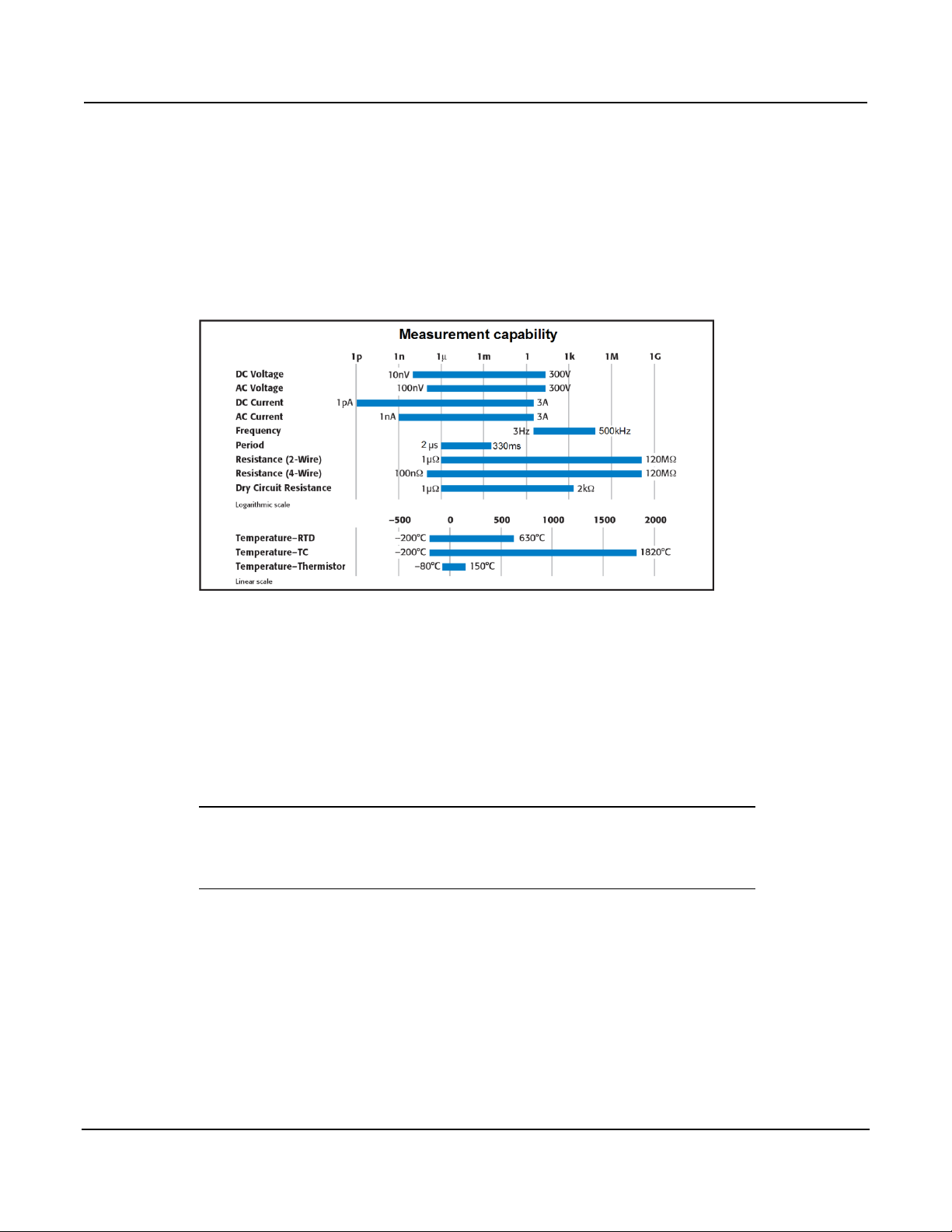
Section 1: Introduction Series 3700 System Switch/Multimeter Reference Manual
1-2 3700S-901-01 Rev. C / July 2008
Measure and switching capabilities
The basic measurement capabilities of Series 3700 systems are summarized in
the following figure.
Figure 1-1: DMM measurement capabilities
Warranty information
Detailed warranty information is located at the front of this manual. Should your
Series 3700 require warranty service, contact the Keithley Instruments
representative or authorized repair facility in your area for further information.
When returning the instrument for repair, be sure to complete the service form at
the back of this manual and give it to the repair facility with all relevant
information.
NOTE The service form requires the serial number of the Series 3700. The
serial number label is located inside the unit on the bottom panel. The
serial number can be viewed by removing the slot covers and/or
switching modules from the mainframe.

Series 3700 System Switch/Multimeter Reference Manual Section 1: Introduction
3700S-901-01 Rev. C / July 2008 1-3
WARNING Before removing (or installing) switching modules, make
sure you turn off the Series 3700 and disconnect the line
cord. Also, remove any other external power connected to
the instrument or switching module(s).
Failure to disconnect power before removing (or installing)
switching modules may result in personal injury or death
due to electric shock.
Displaying the unit's serial number
To display the serial number on the front panel:
NOTE If the Series 3700 is in remote mode, press the EXIT key once to
place the unit in local mode.
1. When in local mode, press the MENU key.
2. Scroll to the SYSTEM-INFO menu and press the ENTER key.
3. On the SYSTEM INFORMATION menu, scroll to the SERIAL# and press
the ENTER key. The Series 3700 serial number will be displayed.


In this section:
Introduction ....................................................................... 2-1
Test Script Processor (TSPTM) ........................................ 2-2
Run-time environment ....................................................... 2-3
Queries ............................................................................. 2-3
Scripts ............................................................................... 2-4
Named scripts ................................................................... 2-5
Programming overview ..................................................... 2-6
Installing the TSPTM software ........................................ 2-10
System connections ........................................................ 2-10
Using Test Script Builder (TSB) ...................................... 2-13
Sending commands and statements ............................... 2-15
Measure voltage ............................................................. 2-15
User scripts ..................................................................... 2-16
Differences: Remote versus local state ........................... 2-32
Test Script Language (TSL) Reference ........................... 2-33
Introduction
Section 2
TSP Programming Fundamentals
Conventional electronic test and measurement equipment responds to
command messages sent to the instrument. Each command message contains
one or more commands that the instrument executes in order. To conduct a test,
a computer controller is programmed to send a sequence of commands to an
instrument. The controller orchestrates the actions of the instrumentation.
Typically, the controller is programmed to request measurement results from the
instrumentation and make test sequence decisions based on those
measurements.
In addition to operating as conventional instruments, Keithley Instruments‟ Test
Script Processor (TSP)-based instruments are capable of executing scripts that
process commands in the instrument rather than needing to be sent from a
computer. Basically, a script allows you to have a program running inside the
instrument to execute a sequence of commands without the need to send them
individually from a computer. Once a script is loaded into the instrument, it only
needs to be called (similar to a function) to execute the desired command
sequence. In the sections that follow, you will learn what a script is, and how to
create, save, and load a script.

Section 2: TSP Programming Fundamentals Series 3700 System Switch/Multimeter Reference Manual
2-2 3700S-901-01 Rev. C / July 2008
Test Script Processor (TSPTM)
The Test Script Processor (TSP) is a scripting engine that runs inside the
instrument. It is capable of running code written in a scripting language called
Lua (http://www.lua.org). This makes the instrument fully capable of interpreting
and executing code in a way that is similar to Visual Basic (VB) or Java, rather
than only responding to single-line commands. Program statements control
script execution and provide capabilities such as variables, functions, branching,
and loop control.
Because scripts are programs, they are written using a programming language,
called the test script language or TSL. TSL is derived from the Lua scripting
language. For details about TSL, see the Test Script Language (TSL) reference
(on page 2-33).
In this manual, we refer to Lua as the "test script language" or "TSL." The TSP
runs portions of TSL code called "chunks." Most messages sent to the
instrument are directly executed by the TSP as TSL chunks. The simplest
messages sent to the instrument are individual instrument control commands.
Even though these messages are executed as TSL chunks, using them is no
different than using a conventional instrument. You send a command message
and the instrument executes that command. When sending individual command
messages, it is irrelevant that the TSP is executing the message as a chunk.
The command set for each TSP-enabled instrument is referred to as the
"instrument control library" or ICL. Each TSP-enabled instrument will have its
own set of ICL commands. Although each TSP-enabled instrument inherits the
same TSL, different instruments extend the language in their own way.
ICL commands are similar to the commands sent to a conventional instrument,
but ICL commands appear like function calls or assignment statements. For
example, the command to set ASCII precision to 10 for ASCII readings is:
format.asciiprecision = 10
Similarly, the command to format readings as ASCII is:
format.data = format.ASCII
These commands do not need to be sent as separate messages. They can be
combined into one message by joining the two commands together with a space
separating them. The resulting chunk would be as follows:
format.asciiprecision = 10 format.data = format.ASCII

Series 3700 System Switch/Multimeter Reference Manual Section 2: TSP Programming Fundamentals
3700S-901-01 Rev. C / July 2008 2-3
Run-time environment
A feature of all scripting environments is the run-time environment. In the TSPTM,
the run-time environment is simply a temporary collection of global variables. A
global variable can be used to remember a value as long as the unit is powered
on and the variable is not assigned a new value. To instruct the instrument to
read the ASCII precision setting and store the result in a global variable named
"x", send:
x = format.asciiprecision
A global variable can be removed from the environment by assigning it the nil
value. For example, the command x = nil will remove the global variable x
from the run-time environment. When the unit is turned off, the entire run-time
environment will be lost.
Queries
TSPTM-enabled instruments do not have inherent query commands. Like any
other scripting environment, the print command and other related print
commands are used to generate output. The print command creates one
response message.
The following chunk is an example that generates an output response message:
x = 10 print(x) 1.000000000e+001
NOTE The output (indicated by the ) may vary, depending on the ASCII
precision setting.

Section 2: TSP Programming Fundamentals Series 3700 System Switch/Multimeter Reference Manual
2-4 3700S-901-01 Rev. C / July 2008
Scripts
When taking advantage of the TSPTM to perform more complicated sequences of
commands, especially sequences utilizing advanced scripting features such as
looping and branching, sending the entire sequence in one message is very
cumbersome. Use the loadscript and endscript messages to collect a
sequence of commands into one chunk.
The loadscript message marks the beginning of a script. The instrument will
collect all following messages until the endscript message is received (the
endscript message marks the end of the script). The TSP-enabled instrument
compiles the test sequence and makes it available to run in a subsequent
message. This chunk is called the "anonymous script."
NOTE Every time the script.run() command is given, the anonymous
script will be executed.
The anonymous script can be run at any time by sending the command
script.run() or script.anonymous(). The anonymous script can be run
many times (it remains in active memory until a new anonymous script is
created). Sending a new script using the loadscript and endscript
messages will instruct the TSP-enabled instrument to replace the anonymous
script with the new script. To see the current contents of the anonymous script,
send the command script.anonymous.list().
Creating and using scripts this way is a very powerful feature of TSP-enabled
instruments, but it is limited to accessing only one script at a time. The solution
to this limitation is to create user-defined named scripts. See Named scripts (on
page 2-5) for information on how to use named scripts, and also how to store
many scripts in the instrument at one time.

Series 3700 System Switch/Multimeter Reference Manual Section 2: TSP Programming Fundamentals
3700S-901-01 Rev. C / July 2008 2-5
Named scripts
The loadscript message can also be used to create named scripts. Loading
a named script does not replace the anonymous script. Instead, a global
variable in the run-time environment is temporarily created to store the script.
Because the script is stored in a global variable, the name of the script must be
a legal TSL variable name. Specify the name of the script in the loadscript
message by separating it from the loadscript keyword with a space
character.
For example, the message loadscript MyScript will instruct the TSPTMenabled instrument to begin gathering command messages that will be used to
create a script named MyScript. After sending the command messages, the
endscript message is still used to indicate the end of the script. Upon receipt
of the endscript message, the instrument will compile the script. If there are
no errors, the script will be made available as the global variable MyScript,
because that is the name we used in the loadscript MyScript message.
After a named script has been successfully sent to the instrument, you can run it
at any time by sending either the MyScript() or
script.user.scripts.MyScript() command.
Named script key points:
Create different script names using loadscript.
Sending a new script with the same name will overwrite (replace) the
previous version.
Sending new scripts with different names will not remove previously sent
scripts.
Using named scripts, any number of scripts can be made available
simultaneously within the limits of the memory available to the run-time
environment.
Named scripts are stored as global variables in the run-time environment.
Therefore, like all other global variables, they are lost when the unit is
powered off.
Nonvolatile storage can be used to store downloaded scripts across power
cycles. See Saving a user script (on page 2-22) for more information.

Section 2: TSP Programming Fundamentals Series 3700 System Switch/Multimeter Reference Manual
2-6 3700S-901-01 Rev. C / July 2008
Programming overview
Chunk defined
A chunk is a single programming statement or a sequence of statements that
are executed sequentially (that is, sent to Lua as a single line). There are nonscripted and scripted chunks.
Single statement chunk
The following programming statement is a chunk:
print ("This is a chunk")
When the above chunk is executed, it returns the following string:
This is a chunk
Multiple-statement chunk
A chunk can contain multiple statements. Each statement in the line of code
must be separated by white space. The following chunk contains two
statements:
print ("This is a chunk") print ("that has two statements")
When the above chunk is executed, the two statements are executed
sequentially, and the following strings are returned:
This is a chunk
that has two statements
Multiple chunks
Each of the following lines of code is a separate chunk. The first chunk sets the
ASCII precision to 10 for readings. The second chunk turns on ASCII readings.
format.asciiprecision = 10
format.data = format.ASCII
Scripted chunk
In a script environment, the chunk is the entire listing of test programming code.
If the two statements in Multiple chunks (on page 2-6) were created as a script,
then those two lines of code would be assembled as one chunk. The instrument
internally constructs a chunk out of a series of messages sent between
loadscript and endscript. Also see Script defined (on page 2-7) for more
details.

Series 3700 System Switch/Multimeter Reference Manual Section 2: TSP Programming Fundamentals
3700S-901-01 Rev. C / July 2008 2-7
Script defined
The Series 3700 utilizes a Test Script Processor (TSP) to process and run
individual chunks or scripts. A script is a collection of instrument control
commands and programming statements. The TSP test script example (on page
2-7) shows an example of how to create and load a script. When this script
(named "test") is run, the message "This is a test" will be displayed on the Series
3700 and sent to the computer.
As shown, a script consists of a chunk of programming code framed by shell
commands. The first shell command in the TSP script example loads the script
named "test." The last shell command marks the end of the script. The chunk in
the TSP script example consists of three lines of code. When the chunk is
executed, the test messages are sent and displayed. The following command
executes the chunk test().
NOTE It is common practice to say that a script is run. In actuality, it is the
chunk in the script that is being run (executed).
Figure 2-1: TSP test script example
A script is loaded into the Series 3700, where it can be run. Running a script
using this method is faster than running a test program from the control
computer because it eliminates the piecemeal transmission process from the
control computer.
A user script is created using your own program or the Test Script Builder
Integrated Development Environment (IDE), which is a supplied software tool
(see Using Test Script Builder (TSB) (on page 2-13)). The user script is loaded
into the Series 3700 and can be saved in nonvolatile memory. These are the
scripts referenced as a "user script" throughout the manual.

Section 2: TSP Programming Fundamentals Series 3700 System Switch/Multimeter Reference Manual
2-8 3700S-901-01 Rev. C / July 2008
Run-time environment
The run-time environment is a collection of global variables (scripts) that you
have created. After scripts are placed into the run-time environment, they are
then ready to be run and/or managed. Scripts are placed in the run-time
environment as follows:
Scripts saved in nonvolatile memory of the Series 3700 are automatically
recalled into the run-time environment when the instrument is turned on.
Named scripts that you have created and loaded are also placed in the run-
time environment. A named script resides in volatile memory and must be
saved to nonvolatile memory to retain it after power-off.
An unnamed script that you have created and loaded is also placed in the
run-time environment. Remember that only one unnamed script, referred to
as the "anonymous script," can be in the run-time environment. If another
unnamed script is created and loaded, it will replace the old unnamed script
in the run-time environment. An unnamed script resides in volatile memory
and must be saved to nonvolatile memory to retain it after power-off.
Nonvolatile memory
New or modified user scripts loaded into the Series 3700 reside in the run-time
environment and are lost when the unit is turned off. To save a script after
power-down, you must save it in nonvolatile memory. When the Series 3700 is
turned back on, all saved scripts will load into the run-time environment.
NOTE Do not confuse the run-time environment with the nonvolatile memory
of the Series 3700. Making changes to a script in the run-time
environment does not affect the stored version of that script. After
making changes, saving the script will overwrite the old version of the
script in nonvolatile memory.
TSPTM programming levels
Instrument control library (ICL) commands and Test Script Language (TSL)
programming statements are used to program and control the Series 3700.
There are two levels of programming:
Sending commands and statements (on page 2-15): Non-scripted chunks
are executed one line at a time by the PC.
User scripts (on page 2-16): A program script is run after you have created
and loaded it into the Series 3700. An interactive script is a type of script
that interacts with the operator. It provides user-defined messages on the
Series 3700 display to prompt the operator to enter parameters from the
front panel.

Series 3700 System Switch/Multimeter Reference Manual Section 2: TSP Programming Fundamentals
3700S-901-01 Rev. C / July 2008 2-9
Programming model for scripts
User-created scripts can be stored in nonvolatile memory. When the Series
3700 is turned on, all user script functions are recalled into the run-time
environment from nonvolatile memory. If any user scripts have been
programmed to run automatically, they will run after all the scripts are loaded.
Any script in the run-time environment can be run from the Test Script Builder or
the user‟s own program. Test data (for example, a reading) is returned from the
Series 3700 to the computer. A user script can be created using the Test Script
Builder or the user‟s own program. Once the user script is loaded into the runtime environment, it is ready to be run. Scripts that are not saved are lost when
the Series 3700 is turned off.
Script management includes commands for the following operations:
Retrieve scripts from nonvolatile memory so they can be modified.
Delete user scripts from nonvolatile memory.
Restore scripts in the run-time environment from nonvolatile memory.
The fundamental programming model for scripts is shown in the following figure.
Figure 2-2: Programming model for scripts

Section 2: TSP Programming Fundamentals Series 3700 System Switch/Multimeter Reference Manual
2-10 3700S-901-01 Rev. C / July 2008
Installing the TSPTM software
Item
Description
1
Analog backplane fuse
2
Slots (6 places)
3
TSP-LinkTM connectors (2 places)
To install the TSP software:
1. Close all programs.
2. Place the CD (Keithley Instruments part number KTS-850B01 or greater)
into your CD-ROM drive.
3. Follow the on-screen instructions.
If your web browser does not start automatically and display a screen with
software installation links, open the installation file (index.html) found on the CD
to initiate automatic installation.
System connections
Up to 64 TSPTM instruments can be used in a test system. The host interface for
the test system can be the GPIB, Ethernet, or USB. For the GPIB, an IEEE-488
cable is used to connect the computer to one of the Series 3700 instruments.
USB and Ethernet also require the appropriate cables. Note that only one cable
is needed to connect to one of the Series 3700 instruments because
communication to the other Series 3700 instruments or TSP-enabled products
can be accomplished using the TSP-LinkTM.
Rear panel summary
Figure 2-3: Rear panel features

Series 3700 System Switch/Multimeter Reference Manual Section 2: TSP Programming Fundamentals
3700S-901-01 Rev. C / July 2008 2-11
Item
Description
4
Instrument fuse
5
Power connector
6
Digital I/O port
7
GPIB connector
8
Ethernet connector
9
USB connector
10
Analog backplane connector
GPIB interface connection
Use a shielded IEEE-488 cable to connect the Series 3700 IEEE-488 connector
to the GPIB connector on the control computer. Connect one end of the cable to
the host computer and the other end to Series 3700. Both cable connections
(see item 1 in GPIB cable (on page 2-11)) are identical. The GPIB cable
connectors are stackable. For additional non-Series 3700 GPIB instruments in
the test system, daisy-chain a GPIB cable from one instrument to another.
NOTE To minimize interference caused by electromagnetic radiation, use
Figure 2-4: GPIB cable
only shielded GPIB cables. Available shielded cables from Keithley
Instruments are the Model 7006 and Model 7007.
Refer to Rear panel summary (on page 2-10) for connector location.

Section 2: TSP Programming Fundamentals Series 3700 System Switch/Multimeter Reference Manual
2-12 3700S-901-01 Rev. C / July 2008
GPIB address
At the factory, the GPIB is set to address value 16. The address value can be
set to any address value between 0 and 30. However, the address cannot
conflict with the address assigned to other instruments in the system.
Change the GPIB address from the GPIB menu. To access the menu, press the
MENU key and select GPIB. The GPIB address is saved in nonvolatile memory.
The address value will not change when power is cycled or a reset command
(reset) is sent. For units without a front panel, use the gpib.address (on page
13-187) ICL command to change the GPIB address setting remotely.
Standard RJ-45 (Ethernet) interface connection
The Series 3700 uses a standard Ethernet connection configuration. It is
designed for a 10/100BaseTX network using standard RJ-45 connectors. This is
an eight-wire connector, but only two sets of wire pairs are used: one pair to
transmit and one pair to receive data.
A 10BaseT network can accommodate transmission speeds up to 10Mbit per
second, where a 100BaseTX network operates at speeds of up to 100Mbit per
second. Both types of networks usually require Ethernet hubs to make
connections.
The exception is a one-to-one connection using a crossover cable, which may
be a 10BaseT or 100BaseTX, depending on the computer‟s Ethernet interface
card and which category of cable is used (the Series 3700 can be directly
connected to a computer's NIC card using an Ethernet crossover cable). Refer
to Rear panel summary (on page 2-10) for connector location.
LAN address
Change or view the LAN address from the LAN menu. To access the menu,
press the MENU key and select LAN. The LAN address is saved in nonvolatile
memory. The address value will not change when power is cycled or a reset
command is sent. For units without a front panel, use the lan.config and
lan.status ICL commands to change or view the LAN settings remotely. See
LAN functions and attributes (on page 13-190) for more information.

Series 3700 System Switch/Multimeter Reference Manual Section 2: TSP Programming Fundamentals
3700S-901-01 Rev. C / July 2008 2-13
USB connection
Connect a computer controller to the Series 3700 rear panel USB (from host)
connector (connect USB flash drive devices to the Series 3700 front panel
USB). Refer to Rear panel summary (on page 2-10) for connector location.
NOTE For your Series 3700 to be recognized by your computer over the
USB interface, the proper driver must be installed. Installing the Test
Script Builder application also installs the applicable USB driver (it
becomes available after installing this software). To complete the USB
driver installation, after installing the Test Script Builder application,
connect the Series 3700 USB connector (rear panel) to the computer.
Using Test Script Builder (TSB)
Test Script Builder is a supplied software tool that can be used to perform the
following operations:
Send ICL commands and TSL statements
Receive responses (data) to commands and scripts
Create and run user scripts
The following figure shows an example of the Test Script Builder. As shown, the
Workspace is divided into three window panes:
Project Navigator (on page 2-14)
Script Editor (on page 2-14)
Programming interaction (on page 2-15)

Section 2: TSP Programming Fundamentals Series 3700 System Switch/Multimeter Reference Manual
2-14 3700S-901-01 Rev. C / July 2008
Figure 2-5: Using Test Script Builder (TSB)
Project Navigator
The Project Navigator resides in the window pane on the left side of the
workspace. The navigator consists of project folders and the script files (.tsp)
created for each project. Each project folder can have one or more script files.
The navigator shown in the graphic in Using Test Script Builder (TSB) (on page
2-13) contains a project named KE37XX_Example_Scripts, which has one script
file, called KE37XX_DMM_Advance_Scan.tsp.
Script Editor
The script chunk is written and/or modified in the Script Editor. Notice that there
is a tab available for each opened script file. A script project is then downloaded
to the Series 3700, where it can be run.

Series 3700 System Switch/Multimeter Reference Manual Section 2: TSP Programming Fundamentals
3700S-901-01 Rev. C / July 2008 2-15
Programming interaction
Up to seven tabs can be displayed in the lower pane of the workspace (the
script editor) to provide programming interaction between the Test Script Builder
and the Series 3700. The instrument console shown in Using Test Script Builder
(TSB) (on page 2-13) is used to send commands to the connected Series 3700.
Retrieved data (for example, readings) from commands and scripts appear in
the instrument console.
Sending commands and statements
Using your own program or the Test Script Builder, non-scripted chunks can be
executed one line at a time. Responses (for example, readings) are then
transmitted back to the computer.
Measure voltage
The digital multimeter (DMM) of the Series 3700 is capable of measuring various
functions. The following code fragment programs the DMM to measure DC
voltage at a specified NPLC and range.
Return the Series 3700 to default settings.
reset()
Set the DMM function to DC volts
dmm.func = 'dcvolts'
Set the NPLC for DC volts
dmm.nplc = 0.1
Set the range for DC volts
dmm.range = 10
Take the DC volts measurement
reading = dmm.measure()
Displays measure voltage reading
print(reading)

Section 2: TSP Programming Fundamentals Series 3700 System Switch/Multimeter Reference Manual
2-16 3700S-901-01 Rev. C / July 2008
Read and write to the digital I/O port
Command
Description
digio.writebit(4,0)
Writes a 0 to bit 4
data=digio.readbit(4)
Reads value at bit 4
print(data)
Displays data on PC
Command
Description
display.clear()
Clears the display
display.settext('Test in
Process')
Displays user message
The digital I/O port of the Series 3700 is used to control external circuitry (such
as a component handler for binning operations). The I/O port has 14 input/output
bits (lines) that can be at TTL logic state 1 (high) or 0 (low). See the pinout in the
graphic in Rear panel summary (on page 2-10) for the Digital I/O port for
additional information.
There are ICL commands to read and/or write to each individual bit, and
commands to read and write to the entire port. Use the following code fragment
to write to one bit of the Digital I/O port. The I/O bit is then read and the state is
returned to the PC, where it is displayed.
Display user-defined messages
The operator can define and display messages on the front panel display of the
Series 3700. The following code fragment displays the "Test in Process"
message on the Series 3700 display:
Displayed messages and input prompts are used in scripts to prompt the
operator to enter parameter values from the front panel. See Interactive script
(on page 2-19) for more information.
User scripts
User scripts can be written using your own program or the Test Script Builder.
User scripts are loaded into the Series 3700 and can be saved in nonvolatile
memory. Scripts not saved in nonvolatile memory will be lost when the Series
3700 is turned off.

Series 3700 System Switch/Multimeter Reference Manual Section 2: TSP Programming Fundamentals
3700S-901-01 Rev. C / July 2008 2-17
Script examples
Script using commands and statements only
The following script closes Channels 1-10 on Slot 3 and measures voltage on
each channel. The ten voltage readings are returned to the host computer, as
well as being stored in a voltage table on the instrument, using the channel
numbers as keys to index the table.
Example exclusive close and measure scripts follow:
User script created in Test Script Builder
voltage = { }
reset()
for j = 3001,3010 do
channel.exclusiveclose('3911,' .. j)
voltage[j] = dmm.measure()
print(voltage[j])
end
User script created in user's own program
loadscript
voltage = { }
reset()
for j = 3001,3010 do
channel.exclusiveclose('3911,' .. j)
voltage[j] = dmm.measure()
print(voltage[j])
end
endscript
NOTE When creating a script using the Test Script Builder, only the chunk is
typed in as shown in the Test script builder example. See Using Test
Script Builder (TSB) (on page 2-13) for details on creating, loading,
and running the script. When creating a script using a programming
language (the User's program script example), shell commands must
be included to manage interactions between the host computer and
TSPTM. The loadscript command starts loading the script into the
Series 3700 and endscript signifies the end of the script.

Section 2: TSP Programming Fundamentals Series 3700 System Switch/Multimeter Reference Manual
2-18 3700S-901-01 Rev. C / July 2008
Script using a function
TSL facilitates grouping commands and statements using the function
keyword. Therefore, a script can also consist of one or more functions. Once a
script has been run, the host computer can then call a function in the script
directly.
The following script contains an ICL command to reset the DMM and a function
(named MyDcv), which takes one parameter to represent the speed of the
measurement. When this script is run, the DMM will be reset and the function
MyDcv will be available for calling.
Example scripts using a function:
Test script builder example
dmm.reset('all')
function MyDcv(speed)
dmm.func = 'dcvolts'
dmm.nplc = speed
dmm.range = 10
reading = dmm.measure()
print(reading)
end
User’s program script example
loadscript
dmm.reset('all')
function MyDcv(speed)
dmm.func = 'dcvolts'
dmm.nplc = speed
dmm.range = 10
reading = dmm.measure()
print(reading)
end
endscript
When calling the function, you must specify the measurement speed in the
argument for the function. For example, to set the measurement speed to 0.5,
call the function as follows:
MyDcv(0.5)
This will set the DMM function to DCV, NPLC to 0.5, and range to 10V. The
voltage reading is sent to the host computer and displayed.

Series 3700 System Switch/Multimeter Reference Manual Section 2: TSP Programming Fundamentals
3700S-901-01 Rev. C / July 2008 2-19
Interactive script
An interactive script prompts the operator (on the Series 3700 display) to input
test parameters (using the Series 3700 front panel). The chunk fragment in the
following table uses display messages to prompt the operator to select a
measure function (DCV or 2-wire) and a range based on function, and to input
the measurement speed. When an input prompt is displayed, the script will wait
until the operator inputs the parameter and/or presses the ENTER key.
The display.prompt command in the following script prompts the user to
input a measurement speed. If a value is not entered, the default level (1) will be
set when ENTER is pressed. The operator will not be able to input values that
are not within the limits (minimum of 0.01 and maximum of 3).
Example of an interactive script chunk fragment (Test Script Builder or user‟s
program):
-- Prompt operator to select function:
myfunc = display.menu ('Select function', 'dcvolts
twowireohms')
-- Now prompt for range based on function selected
if (myfunc == 'dcvolts') then
myrange = display.menu('Select range', '10 100')
if (myrange == '10') then
range_value = 10
else
range_value = 100
end
else
myrange = display.menu('Select range', '1000 10000')
if (myrange == '1000') then
range_value = 1000
else
range_value = 10000
end
end
-- Prompt operator to set (input) measurement speed
speed = display.prompt('0.00', 'NPLC', 'Enter measure
speed', 1, 0.01, 3)
-- Wait for operator to set the measurement speed
dmm.reset('all')
dmm.func = myfunc
dmm.range = range_value
dmm.nplc = speed
print(dmm.measure())

Section 2: TSP Programming Fundamentals Series 3700 System Switch/Multimeter Reference Manual
2-20 3700S-901-01 Rev. C / July 2008
Creating a user script
loadscript
loadscript name
(chunk)
(chunk)
endscript
endscript
loadandrunscript
loadandrunscript name
(chunk)
(chunk)
endscript
endscript
To create a script and load it, the test program (chunk) must be framed by the
following shell commands: loadscript or loadandrunscript, and
endscript.
Load only
The following scripts will load only into the run-time environment of the Series
3700. The script on the left is unnamed (anonymous script), while the one on the
right is named (where name is the user-defined name):
Load and run
The following scripts will load into the run-time environment and then run.
Remember that when a script is run, only the chunk is executed. The script on
the left is unnamed (anonymous script), while the one on the right is named
(where name is the user-defined name):
Details about loadscript and loadandrunscript are provided as follows:
loadscript
loadscript name
Where: name is the user-assigned name for the script.
The loadscript shell command loads the script into the run-time environment.
The script can be assigned a name or it can be left nameless. If you are
assigning a name that already exists for another loaded script, the old script will
be overwritten with the new script.
If a script is not named when it is loaded into the run-time environment, it will be
lost when another nameless script (anonymous script) is loaded or when the
Series 3700 is turned off. After loading the unnamed script (anonymous), use
the run(), script.run(), script.anonymous(), or
script.anonymous.run() commands to run it.

Series 3700 System Switch/Multimeter Reference Manual Section 2: TSP Programming Fundamentals
3700S-901-01 Rev. C / July 2008 2-21
A script saved in nonvolatile memory named autoexec has special properties
that cause it to run automatically after the Series 3700 is powered on and all
autorun scripts have been executed. For details, see Autoexec script (on page
2-26) and Autorun scripts (on page 2-26).
loadandrunscript
loadsandrunscript name
Where: name is the user-assigned name for the script.
These commands are similar to the loadscript commands, except that the
script will execute (run) after it is loaded into the run-time environment. Also, the
autorun attribute for a named script will be set to "yes" (see Autorun scripts (on
page 2-26)).
Creating a user script (alternative)
An alternate way to create a script is to use script.new, which creates a script
from a chunk of Lua code, using the following command:
myscript = script.new(code, name)
Where:
myscript is the created script or nil, if an error occurred. If the name
parameter is an empty string, this is the only handle to the created script.
code is the string representing a chunk of Lua code, which will be used as
the script body.
name (optional) is the name of the script to be created. The script's name
attribute is initialized to this value, which (if not the empty string) also serves
as the key used to access the script through the script.user.scripts
table. The default is the empty string.
If the name of the script.new script conflicts with the name of an existing
script in the script.user.scripts table, the existing script will be unnamed
(that is, its name attribute will be set to the empty string) before it is replaced in
the script.user.scripts table by the newly-created script.
Example:
To create a new global script called MyTest8 and assign the name attribute to
MyTest8 that displays "Hello from MyTest8" on the display, use the following
command:
MyTest8 = script.new("display.clear()
display.settext('Hello from MyTest8')", 'MyTest8')
To run this script:
MyTest8()

Section 2: TSP Programming Fundamentals Series 3700 System Switch/Multimeter Reference Manual
2-22 3700S-901-01 Rev. C / July 2008
Get or change the name attribute of a script
The following commands are used to get or change the name attribute of a
script:
val = myscript.name -- read the name of myscript
myscript.name = val -- change the name of myscript
Where:
myscript is the script
val is the name of the script
This attribute may optionally be initialized when the script is created. See
Loading a user script (on page 2-24) (script.load) and Creating a user script
(alternative) (on page 2-21) (script.new) for details.
This attribute must be either a valid Lua identifier or the empty string. Changes
to its value are reflected in the script.user.scripts table. Setting the
attribute to the empty string will remove the script from the table completely.
For example, a new script can be created without naming it, such as:
MyTest7 = script.new("display.clear()
display.settext('Hello from my test')")
To run this script, type:
MyTest7()
If print(MyTest7.name) is executed, it will print a blank line because the
name is an empty string.
To name the script "MyTest7" and read the name, send:
MyTest7.name = 'MyTest7'
print(MyTest7.name) --> MyTest7 is displayed
Saving a user script
A created and loaded script does not have to be saved in the nonvolatile
memory of the Series 3700 before it can be run. However, an unsaved script will
be lost when the Series 3700 is turned off.

Series 3700 System Switch/Multimeter Reference Manual Section 2: TSP Programming Fundamentals
3700S-901-01 Rev. C / July 2008 2-23
Saving a named script
Only a named script can be saved in nonvolatile memory of the Series 3700.
After creating and loading a named script, use one of the following commands to
save it.
myscript.save() -- To save script in internal
memory
myscript.save('filename') -- To save script on flash drive
Where:
myscript is the user-defined name of the script.
filename is a filename for the script to save it on a user-supplied USB
flash drive.
The save command will save the script to internal nonvolatile memory if no
filename is specified. If a script is not saved in nonvolatile memory, the script will
be lost when the Series 3700 is turned off.
The myscript.save() command saves the script under the original name that
was created and loaded. The myscript.save('filename') shell command
is used to save the script to a user-supplied USB flash drive. If you save the
script to a filename that already exists, it will be overwritten. The filename may
have an absolute or relative path to the current working directory. If using an
absolute path, include "/usb1/" at the beginning to denote the flash drive. Also, if
the filename includes an extension, it must be ".tsp"; otherwise, an error occurs.
If no extension is specified, the ".tsp" extension will be added.
Examples:
Assume a script named "test1" has been created and loaded. The following
command saves the script in nonvolatile memory:
test1.save()
To save the script named "test1" under a filename ("test2") on a user-
supplied USB flash drive, send the following command:
test1.save('/usb1/test2.tsp')
To save the anonymous script, provide a valid name for the name attribute
of the anonymous script. Once the anonymous script is named, it can be
saved. For example, to save the anonymous script as "MyTest":
script.anonymous.name = 'MyTest'
script.anonymous.save()
To execute anonymous script that was just saved as 'MyTest':
script.user.scripts.MyTest()

Section 2: TSP Programming Fundamentals Series 3700 System Switch/Multimeter Reference Manual
2-24 3700S-901-01 Rev. C / July 2008
The anonymous script may be saved to the flash drive without setting the
name attribute. For example, to save the anonymous script on the flash
drive as "MyAnonTest.tsp":
script.anonymous.save('/usb1/MyAnonTest.tsp')
Loading this file ('MyAnonTest.tsp') back into the unit from the flash drive will
cause an existing anonymous script to be overwritten.
Loading a user script
The following command is used to create a script from a specified file:
myscript = script.load(file, name)
Where:
myscript is the created script, or nil if an error occurred. If the name
parameter is an empty string, or if the name is absent or nil, and the script
name cannot be extracted from the file, this will be the only handle to the
created script.
file is the absolute or relative path and filename of the script file to import.
name (optional) is the name of the script to be created. The script's name
attribute is initialized to this value, which (if not an empty string) also serves
as the key used to access the script through the script.user.scripts
table.
If the name parameter is present (not nil), any script name embedded in the file
is ignored. Also, if name conflicts with the name of an existing script in the
script.users.scripts table, the existing script will be unnamed (that is, its
name attribute will be set to the empty string) before it is replaced in the
script.user.scripts table by the newly-created script.
If the name parameter is absent or nil, the command attempts to extract the
script's name from the file. Any conflict between the extracted name and that of
an existing script in the script.user.scripts table generates an error. If the
script name cannot be extracted, the created script's name attribute is initialized
to the empty string, and must be set to a valid non-empty string before saving
the script to internal memory.
The file to be uploaded must contain the loadscript or loadandrunscript
keywords, the script's body, and the endscript keyword.
Examples:
To load a file called "MyUserList.tsp" from the USB flash drive and name the
script "myuserlist," send the following command:
mylist = script.load('MyUserList.tsp', 'myuserlist')

Series 3700 System Switch/Multimeter Reference Manual Section 2: TSP Programming Fundamentals
3700S-901-01 Rev. C / July 2008 2-25
To execute the myuserlist script:
script.user.scripts.myuserlist()
mylist()
Running a user script
Running an unnamed script
There can only be one unnamed (anonymous) script in the run-time
environment. If another anonymous script is created and loaded, the previous
anonymous script will be removed from the run-time environment. On the front
panel, an unnamed script appears as <anonymous>. Use one of the following
commands to execute the chunk of the last loaded anonymous script. The
following four commands perform the same operation.
run()
script.run()
script.anonymous()
script.anonymous.run()
Running a named script
Any named script that is in the run-time environment can be run using one of the
following commands. The following four commands perform the same operation.
myscript()
myscript.run()
script.user.scripts.myscript()
script.user.scripts.myscript.run()
Where: myscript is the user-defined name of the script.
Example:
Assume a script named "test3" has been loaded into the run-time environment.
The following commands execute the chunk of the script.
test3()
script.user.scripts.test3()
Running scripts automatically
Scripts can be set to run automatically when the Series 3700 is turned on. You
can assign one or more Autorun scripts (on page 2-26) and one Autoexec script
(on page 2-26).

Section 2: TSP Programming Fundamentals Series 3700 System Switch/Multimeter Reference Manual
2-26 3700S-901-01 Rev. C / July 2008
Autorun scripts
When a saved script is set to autorun, it will automatically load and run when the
Series 3700 is turned on. Any number of scripts can be set to autorun. The run
order for these scripts is arbitrary, so make sure the run order is not important.
To set a script for autorun, set one of the following autorun attributes to "yes."
Setting it to "no" disables autorun.
myscript.autorun
script.user.scripts.myscript.autorun
Where: myscript is the user-defined name of the script.
Make sure to save the script in nonvolatile memory after setting the autorun
attribute.
Example:
Assume a script named "test5" is in the run-time environment. Set the script to
autorun as follows:
test5.autorun = "yes" or script.user.scripts.test5.autorun
= "yes"
test5.save()
The next time the Series 3700 is turned on, the "test5" script will automatically
load and run.
NOTE The loadandrunscript name command sets the autorun attribute
for that script to "yes." To cancel it, set the autorun attribute to "no"
and save the script.
Autoexec script
One script can be designated as the autoexec script. When the Series 3700 is
turned on, the autoexec script will start after all the autorun scripts have run.
loadscript autoexec
loadandrunscript autoexec
Form an autoexec script by creating a new script and naming it autoexec (as
shown above using loadscript or loadandrunscript). After loading the
new script, send the autoexec.save() command to save it in nonvolatile
memory. See Creating a user script (on page 2-20) for details on creating a
script.

Series 3700 System Switch/Multimeter Reference Manual Section 2: TSP Programming Fundamentals
3700S-901-01 Rev. C / July 2008 2-27
Running a user script from the Series 3700 front panel
Use the following commands to enter or delete a name in the User menu option
from the LOAD key:
display.loadmenu.add(displayname, chunk)
display.loadmenu.delete(displayname)
Where:
displayname is the name to be added to (or deleted from) the User menu.
chunk is the name of the chunk (Lua executable code).
It does not matter what order the items are added to the User menu, as they will
be displayed in alphabetical order when the menu is selected.
Example:
Assume a user script named "Test9" has been loaded into the run-time
environment. Add the script name to the User menu for the chunk as follows:
display.loadmenu.add("Test9", "Test9()")
To run the chunk from the front panel:
1. Press the LOAD key.
2. Select USER and press the ENTER key.
3. Select the user chunk from list and press the ENTER key. The chunk is
loaded for front panel execution.
NOTE If you're used to using print in Test Script Builder, note that the
output of the prints using this procedure will not function the same
as when you're in Test Script Builder. You may find that it makes
more sense to use Test Script Builder to get the output you need.
4. Press the RUN key to execute.
To run a script directly without adding it to the USER menu:
1. Press the LOAD key.
2. Select SCRIPTS and press the ENTER key. There may be a short pause
before a menu is displayed that represents the scripts in the instrument.
3. Select the script from the list and press the ENTER key. Now the script is
loaded for front panel execution.
NOTE If you're used to using print in Test Script Builder, note that the
output of the prints using this procedure will not function the same
as when you're in Test Script Builder. You may find that it makes
more sense to use Test Script Builder to get the output you need.
4. Press the RUN key to execute.

Section 2: TSP Programming Fundamentals Series 3700 System Switch/Multimeter Reference Manual
2-28 3700S-901-01 Rev. C / July 2008
Loading a script from the Series 3700 front panel
To load a script from a USB flash drive:
1. Press the MENU key to open the main menu.
2. Select the SCRIPT option.
3. Select the LOAD option. A menu is displayed that includes the USB option.
4. Select the USB option. A menu is displayed that lists the .tsp files and
directories on the flash drive. If you select a directory, a new menu is
displayed that lists the .tsp files and directories in that directory.
5. Selecting a .tsp file will cause the system to attempt to load the file.
If the file is not a valid script file, an error message is posted and no
further action is taken.
Loading an anonymous script will overwrite the existing anonymous
script.
A file that does not contain loadscript and endscript shell
keywords will be loaded as an anonymous script.
The display will indicate if a named script already exists in memory. If it
does, you will be prompted to overwrite the script. The display returns to
step 4 if an error occurs or if you select "No" when prompted to
overwrite the script. Otherwise, the display proceeds to step 6 after
indicating that the script loaded successfully.
The script is loaded using the name that follows the loadscript shell
keyword instead of filename. Also, the script is loaded into the
script.user.scripts table.
6. The SCRIPT ACTION menu lists the options of ACTIVE_FOR_RUN or
SAVE_INTERNAL. Proceed to step 7 if ACTIVE_FOR_RUN is selected or
step 8 if SAVE_INTERNAL is selected.
7. ACTIVE_FOR_RUN associates the script with the RUN button if you
selected YES. The script replaces the active executable chunk selected
under the LOAD button. If NO is selected, the display returns to step 6.
8. If you select SAVE_INTERNAL, you will be prompted to save the script into
internal memory. The ICL equivalent is myscript.save() with no
parameters. If you select YES, proceed to step 5 of Saving a script from the
Series 3700 front panel (on page 2-29). If NO is selected, the display returns
to step 6. Note that anonymous scripts cannot be saved internally.

Series 3700 System Switch/Multimeter Reference Manual Section 2: TSP Programming Fundamentals
3700S-901-01 Rev. C / July 2008 2-29
Saving a script from the Series 3700 front panel
To save a script to internal memory or a USB flash drive:
1. Press the MENU key to bring up the Main Menu.
2. Select the SCRIPT option.
3. Select the SAVE option to bring up a menu listing the scripts available to
save from the script.user.scripts table. This may take several
seconds before displaying.
4. Select the script that you want to save. It may be the anonymous script or
one of the user-named scripts.
5. Select where you want to save the script, either in internal memory or on the
USB flash drive. You cannot save the anonymous script to internal memory.
Only named scripts can be saved internally.
Select INTERNAL to save the script to internal memory using the
script's name attribute.
Select USB, and a prompt will display for a filename using the first 13
characters of the name attribute as a default name followed by a
modifiable 3-digit number. If the filename exists, the word (overwrite)
appears on the display. The file is automatically saved with a .tsp
extension.
Modifying a user script
You can modify a user script stored in nonvolatile memory by retrieving the
script listing, which can then be modified, loaded, and saved in nonvolatile
memory. See Retrieving a user script (on page 2-30) for details.
NOTE If you are using the Test Script Builder to modify a user script stored in
nonvolatile memory, retrieve the script listing from the Project
Navigator.

Section 2: TSP Programming Fundamentals Series 3700 System Switch/Multimeter Reference Manual
2-30 3700S-901-01 Rev. C / July 2008
Script management
Retrieving a user script
You can retrieve the source code contained in a user script from nonvolatile
memory, which can then be modified and saved as a user script under the same
name or a new name.
NOTE You can load a modified user script into the Series 3700 using the
same name or a new name.
The following command returns a catalog listing of the user scripts stored in the
Series 3700:
script.user.catalog()
Example:
To retrieve the catalog listing for user scripts:
for name in script.user.catalog() do
print (name)
end
The following function retrieves the source code of a saved script. The script
chunk is returned, along with the shell keywords (loadscript or
loadandrunscript, and endscript):
myscript.list()
Where: myscript is the user-defined name of the script.
Example:
To retrieve the source of a saved script named "test7":
userscriptlist = test7.list()
print (userscriptlist)
NOTE To see the contents of the anonymous script, use the
script.list.anonymous.list() command.

Series 3700 System Switch/Multimeter Reference Manual Section 2: TSP Programming Fundamentals
3700S-901-01 Rev. C / July 2008 2-31
Deleting a script from the system
To completely remove a script from the system, all references to the script will
need to be deleted from the run-time environment. A script may be removed
from the run-time environment by assigning it to nil. For example, to remove
the script named "test8" from the run-time environment, send the following code
to set test8 to a nil value:
test8 = nil
To delete a script from the script.user.scripts table, set the name
attribute to an empty string(""), which makes the script nameless. This does not
make the script become the anonymous script. For example, to remove the
script named "test8" from the script.user.scripts table, send the following
code to set the name attribute for test8 as an empty string:
script.user.scripts.test8.name = ""
Replacing, changing, or deleting a script from the run-time environment does not
remove the script from nonvolatile memory. A script can be permanently
removed from nonvolatile memory sending either of the following commands:
script.delete("name")
script.user.delete("name")
Where: name is the user-defined name of the script.
Example:
To delete a user script named "test8" from nonvolatile memory:
script.delete("test8")
Restoring a script in the run-time environment
A script is inherently a global variable that can be replaced by assigning a new
value or by loading a new script with the same name. It can also be removed
from the run-time environment by assigning it the nil value. A script can be
restored from nonvolatile memory back into the run-time environment using
either of the following commands:
script.restore("name")
script.user.restore("name")
Where: name is the user-defined name of the script to be restored.
Example:
To restore a user script named "test9" from nonvolatile memory:
script.restore("test9")

Section 2: TSP Programming Fundamentals Series 3700 System Switch/Multimeter Reference Manual
2-32 3700S-901-01 Rev. C / July 2008
Differences: Remote versus local state
The Series 3700 can be in either the local state or the remote state.
When it is in the local state (REM annunciator off), the instrument is
operated using the front panel controls.
When it is in the remote state (REM annunciator on), instrument operation is
controlled by the computer.
When the instrument is powered-on, it is in the local state.
Remote state
The following actions will place the instrument in the remote state:
Sending a command from the computer to the instrument
Running a script (a USER test) from the front panel; after the test is
completed, the instrument will return to the local mode
Opening communications between the instrument and Test Script Builder
Web-control (logging in to the Series 3700 web interface)
While the instrument is in the remote state, front panel controls are disabled.
However, the LOCAL key will be active unless it has not been explicitly locked
out by the user program. When an interactive script is running, use the activated
front panel controls to input parameter values.
Local state
The following actions will cancel the remote state and return the instrument to
the local state:
Cycling power for the instrument
Pressing front panel LOCAL key (if it is not locked out)
Sending the abort command from the PC
Clicking the Abort Execution icon on the toolbar of the Instrument Console
for Test Script Builder
After a front panel script (a USER test) is completed, the instrument will return to
the local state.
TSP-LinkTM system
A test system can be expanded to include up to 64 instruments that are enabled
using TSP-Link. The system can be stand-alone or PC-based.

Series 3700 System Switch/Multimeter Reference Manual Section 2: TSP Programming Fundamentals
3700S-901-01 Rev. C / July 2008 2-33
Stand-alone system
and
function
return
elseif
nil
until
for
repeat
else
local
true
false
then
do
in
break
if
or
end
not
while
A script can be run from the front panel of any node (instrument) in the system.
When a script is run, all nodes in the system go into remote operation (REM
annunciators turn on). The node running the script becomes the primary node
and can control all of the other nodes, which become its subordinates. When the
script is finished running, all the nodes in the system return to local operation
(REM annunciators turn off), and the primary/subordinate relationship between
nodes is dissolved.
PC-based system
When using a computer, the GPIB, LAN, or USB interface to any single node
becomes the interface to the entire system. When a command is sent through
one of these interfaces, all nodes go into remote operation (REM annunciators
turn on).
The node that receives the command becomes the primary node and can
control all of the other nodes, which become its subordinates. In a PC-based
system, the primary/subordinate relationship between nodes can only be
dissolved by sending an abort command.
Test Script Language (TSL) Reference
Introduction
A script is a program written using the Test Script Language (TSL) that the Test
Script Processor (TSP) executes. TSL is an efficient language, with simple
syntax and extensible semantics. TSL is derived from the Lua programming
language. See the website for the Lua Programming Language
(http://www.lua.org) for more information. Another source of useful information is
lua-users (http://lua-users.org), created for and by users of Lua programming
language.
Lua programming language reserved words:

Section 2: TSP Programming Fundamentals Series 3700 System Switch/Multimeter Reference Manual
2-34 3700S-901-01 Rev. C / July 2008
Variables and types
var = nil
var is nil.
var = 1.0
var is now a number.
var = 0.3E-12
var is still a number.
var = 7
var is still a number.
var = "Hello world!"
var is now a string.
var = "I said, Hello world!"
var is still a string.
var = function(a, b) return(a+b)
end
var is now a function that adds two
numbers.
var = {1, 2., 3.00e0}
var is now a table (in other words, an
array) with three initialized members.
TSL has six basic types: nil, boolean, number, string, function, and
table. TSL is a dynamically typed language, which means variables do not
need to be declared as a specific type. Instead, variables assume a type when a
value is assigned to them. Therefore, each value carries its own type.
If a variable has not been assigned a value, the variable defaults to the type
nil. All numbers are real numbers. There is no distinction between integers and
floating-point numbers in TSL.
nil is a type with a single value, nil, whose main property is to be different
from any other value. Global variables have a nil value by default before a first
assignment, and you can assign nil to a global variable to delete it. TSL uses
nil as a non-value that represents the absence of a useful value.
Operators
Arithmetic operators:
+ (addition)
- (subtraction)
* (multiplication)
/ (division)
- (negation)

Series 3700 System Switch/Multimeter Reference Manual Section 2: TSP Programming Fundamentals
3700S-901-01 Rev. C / July 2008 2-35
Relational operators:
< (less than)
> (greater than)
<= (less than or equal)
>= (greater than or equal)
~= (not equal)
== (equal)
Logical operators:
and
or
Functions
TSL allows you to define functions which can take a pre-defined number of
parameters and return multiple parameters. Functions are first-class values in
TSL, which means that they can be stored in variables, passed as arguments,
and returned as results if desired.
This is a function called "add_two":
function add_two(parameter1, parameter2)
return(parameter1 + parameter2)
end
print(add_two(3, 4))
This is an alternate syntax for defining a function, called "add_three":
add_three = function(parameter1, parameter2, parameter3)
return(parameter1 + parameter2 + parameter3)
end
print(add_three(3, 4, 5))
not

Section 2: TSP Programming Fundamentals Series 3700 System Switch/Multimeter Reference Manual
2-36 3700S-901-01 Rev. C / July 2008
This function returns multiple parameters (sum, difference, and ratio of the two
numbers passed to it):
function sum_diff_ratio(parameter1, parameter2)
psum = parameter1 + parameter2
pdif = parameter1 – parameter2
prat = parameter1 / parameter2
return psum, pdif, prat
end
sum, diff, ratio = sum_diff_ratio(2,3)
print(sum)
print(diff)
print(ratio)
The function's output is:
7
12
5
-1
0.66666
Tables/arrays
TSL makes extensive use of the data type "table," which is a very flexible arraylike data type.
To define a table:
-- A table with four elements, which are numbers.
atable = {1, 2, 3, 4}
Send the following commands to print it:
-- Tables are indexed on one, NOT zero. atable[index] is
true if there is an element at that index. nil is
returned otherwise. 0 does NOT evaluate to false, only
nil does.
i = 1
Index into table using a number.
while atable[i] do
print (atable[i])
i = i + 1
end
The command's output is:
1
2
3
4

Series 3700 System Switch/Multimeter Reference Manual Section 2: TSP Programming Fundamentals
3700S-901-01 Rev. C / July 2008 2-37
Tables can be indexed using element names instead of numeric indices.
clr
A string containing the color of the circle
diam
A number containing the diameter of the circle
setdiam
A function, or method, used to change the diameter
^ not
- (unary)
* / + - .. (concatenation)
< <= >= ~= ==
and
Because functions are first-class variables, tables can be used to create
"pseudoclasses." Classes are often used in object-oriented programming.
Below is a table used to create a circle pseudoclass. It has 3 elements:
circle = {clr = 'red', diam = 1, setdiam = function(d)
circle['diam']=d end}
-- Index using a string; print the clr property.
print(circle['clr'])
-- Index using a string; print the diam property.
print(circle['diam'])
-- Change the diam element by calling setdiam.
circle['setdiam'](2)
-- Print the diameter of the circle; circle['diam'] is a
simpler syntax of circle.diam
print(circle.diam)
-- Change the diameter of the circle again.
circle.setdiam(3)
-- Print diam property again using simple syntax.
print(circle.diam)
Output of code above:
red
1
2
3
Precedence
Operator precedence in TSL follows the table below, from higher to lower
priority:

Section 2: TSP Programming Fundamentals Series 3700 System Switch/Multimeter Reference Manual
2-38 3700S-901-01 Rev. C / July 2008
or
a+i < b/2+1
(a+i)< ((b/2)+1)
5+x^2*8
5+((x^2)*8)
a < y and y <= z
(a < y) and (y <= z)
-x^2
-(x^2)
x^y^z
x^(y^z)
All operators are left associative, except for "^" (exponentiation) and "..", which
are right associative. Therefore, the following expressions on the left are
equivalent to those on the right:
Logical operators
The logical operators are and, or, and not. Like control structures, all logical
operators consider false and nil as false and anything else as true.
The operator and returns its first argument if it is false, otherwise it returns its
second argument.
The operator or returns its first argument if it is not false; otherwise it returns its
second argument:
print(4 and 5)
print(nil and 13)
print(false and 13)
print(4 or 5)
print(false or 5)
Output of code above:
5
nil
false
4
5
Both and and or use short-cut evaluation; that is, they evaluate their second
operand only when necessary. A useful TSL construct is x = x or v, which is
equivalent to:
if not x then x = v end

Series 3700 System Switch/Multimeter Reference Manual Section 2: TSP Programming Fundamentals
3700S-901-01 Rev. C / July 2008 2-39
For example, it sets x to a default value v when x is not set (provided that x is
not set to false).
To select the maximum of two numbers x and y, use the following statement
(note the and operator has a higher precedence than or):
max = (x > y) and x or y
When x > y is true, the first expression of the and is true, so the and results in
its second argument x (which is also true, because it is a number), and then the
or expression results in the value of its first expression, x. When x > y is false,
the and expression is false and so are the or results in its second expression,
y.
The operator not always returns true or false:
print(not nil)
print(not false)
print(not 0)
print(not not nil)
Output of code above:
true
true
false
false
Concatenation
TSL denotes the string concatenation operator by ".." (two dots). If any of its
operands is a number, TSL converts that number to a string:
print("Hello ".."World")
print(0 .. 1)
Output of code above:
Hello World
01

Section 2: TSP Programming Fundamentals Series 3700 System Switch/Multimeter Reference Manual
2-40 3700S-901-01 Rev. C / July 2008
Branching
TSL uses the if keyword to do conditional branching.
--
--------------- IF blocks ---------------
--
-- This is if expression 1. Zero is true in Lua language;
this is a contrast to C language, where 0 evaluates
false. In TSL, nil is false and everything else is true.
if 0 then
print("Zero is true!")
else
print("Zero is false.")
end
x = 1
y = 2
-- This is if expression 2.
if (x and y) then
print("' if ' expression 2 was not false.")
end
-- This is if expression 3.
if (x or y) then
print("' if ' expression 3 was not false.")
end
-- This is if expression 4.
if (not x) then
print("' if ' expression 4 was not false.")
else
print("' if ' expression 4 was false.")
end
This is if expression 5.
if x == 10 then
print("x = 10")
elseif y > 2 then
print("y > 2")
else
print("x is not equal to 10, and y is not less than 2.")
end

Series 3700 System Switch/Multimeter Reference Manual Section 2: TSP Programming Fundamentals
3700S-901-01 Rev. C / July 2008 2-41
Output of code above:
Zero is true!
' if ' expression 2 was not false.
' if ' expression 3 was not false.
' if ' expression 4 was false.
x is not equal to 10, and y is not less than 2.
Loop control
TSL has familiar constructs for doing things repetitively or until an expression
evaluates to false.
The following code contains an example iteration:
list = {"One", "Two", "Three", "Four", "Five", "Six"}
--
--------------- For loop ---------------
--
print("Counting from one to three:")
for element = 1, 3 do
print(element, list[element])
end
print("Counting from one to four,")
print("in steps of two:")
for element = 1, 4, 2 do
print(element, list[element])
end
--
--------------- WHILE loop ---------------
--
-- Will exit when list[element] = nil
print("Counting elements in list")
print("on numeric index")
element = 1
while list[element] do
list[element] = nil
print(element, list[element])
element = element + 1
end

Section 2: TSP Programming Fundamentals Series 3700 System Switch/Multimeter Reference Manual
2-42 3700S-901-01 Rev. C / July 2008
--
--------------- REPEAT loop ---------------
--
print("Counting elements in list")
print("using repeat")
element = 1
repeat
print(element, list[element])
element = element + 1
until not list[element]
Output of code above:
Counting from one to three:
1 One
2 Two
3 Three
Counting from one to four,
in steps of two:
1 One
3 Three
Counting elements in list
on numeric index
1 One
2 Two
3 Three
4 Four
5 Five
6 Six
Counting elements in list
using repeat
1 One
2 Two
3 Three
4 Four
5 Five
6 Six
Standard libraries
In addition to the standard programming constructs above, TSL includes
standard libraries that contain useful functions for string manipulation,
mathematics, and more. TSL also includes instrument control extension
libraries, which provide programming interfaces to the instrumentation
accessible by the TSPTM. These libraries are automatically loaded when the TSP
starts and do not need to be managed by the programmer.

Series 3700 System Switch/Multimeter Reference Manual Section 2: TSP Programming Fundamentals
3700S-901-01 Rev. C / July 2008 2-43
Base library functions
print(x)
Prints the argument x to the active host interface, using
the tostring() function to convert x to a string.
collectgarbage([limit])
Sets the garbage-collection threshold to the given limit (in
Kbytes) and checks it against the byte counter. If the new
threshold is smaller than the byte counter, then TSL
immediately runs the garbage collector. If the limit
parameter is absent, it defaults to 0 (thus forcing a
garbage-collection cycle). See NOTE below for more
information.
gcinfo()
Returns the number of Kbytes of dynamic memory that
TSPTM is using.
tonumber(x [,base])
Returns x converted to a number. If x is already a
number, or a convertible string, then the number is
returned; otherwise, it returns nil.
An optional argument specifies the base to interpret the
numeral. The base may be any integer between 2 and
36, inclusive. In bases above 10, the letter A (in either
upper or lower case) represents 10, B represents 11, and
so forth, with Z representing 35. In base 10, the default,
the number may have a decimal part, as well as an
optional exponent. In other bases, only unsigned integers
are accepted.
tostring(x)
Receives an argument of any type and converts it to a
string in a reasonable format.
type(v)
Returns the type of its only argument, coded as a string.
The possible results of this function are: nil, number,
Boolean, table, or function.
NOTE TSL does automatic memory management, which means you do not have to allocate
memory for new objects and free it when the objects are no longer needed. TSL
manages memory automatically by occasionally running a garbage collector to
collect all "dead" objects (that is, those objects that are no longer accessible from
TSL). All objects in TSL are subject to automatic management: tables, variables,
functions, threads, and strings.
TSL uses two numbers to control its garbage-collection cycles. One number counts
how many bytes of dynamic memory TSL is using; the other is a threshold. When
the number of bytes crosses the threshold, TSL runs the garbage collector, which
reclaims the memory of all "dead" objects. The byte counter is adjusted, and then
the threshold is reset to twice the new value of the byte counter.

Section 2: TSP Programming Fundamentals Series 3700 System Switch/Multimeter Reference Manual
2-44 3700S-901-01 Rev. C / July 2008
String library functions
This library provides generic functions for string manipulation, such as finding
and extracting substrings. When indexing a string in TSL, the first character is at
position 1 (not 0 as in ANSI C). Indices may be negative and are interpreted as
indexing backward from the end of the string. Thus, the last character is at
position 1, and so on.
-- Returns the internal numerical code of the i-th
character of string s, or nil if the index is out of
range.
string.byte(s [,i])
-- Receives 0 or more integers. Returns a string with
length equal to the number of arguments, in which each
character has the internal numerical code equal to its
corresponding argument.
string.char(i1, i1, …)
-- Returns a formatted version of its variable number of
arguments following the description given in its first
argument, which must be a string. The format string
follows the same rules as the print family of ANSI C
functions. The only differences are that the
options/modifiers *, l, L, n, p, and h are not supported.
The options c, d, E, e, f, g, G, I, o, u, X, and x all
expect a numeric argument, where s expects a string
argument. String values to be formatted with %s cannot
contain embedded zeros.
string.format(fs, e1, e2, …)
-- Returns the length of the strings.
string.len(s)
-- Returns a copy of the string s with all uppercase
letters changed to lowercase.
string.lower(s)
-- Returns a string that is the concatenation of n copies
of the string s.
string.rep(s, n)
-- Returns the substring of s that starts at i and continues
until j. i and j may be negative. If j is absent, then it
is assumed to be equal to –1, which is the same as the
string length. In particular, the call string.sub(s,1,j)
returns a prefix s with length j, and string.sub(s, -i)
returns a suffix s with length i.
string.sub(s, i [,j])
-- Returns a copy of the string s with all lowercase
letters changed to uppercase.
string.upper(s)

Series 3700 System Switch/Multimeter Reference Manual Section 2: TSP Programming Fundamentals
3700S-901-01 Rev. C / July 2008 2-45
Math library functions
Function
Definition
math.abs(x)
Returns the absolute value of the argument x.
math.acos(x)
Returns the principal value of the trigonometric arc cosine function
of x.
math.asin(x)
Returns the principal value of the trigonometric arc sine function of
x.
math.atan(x)
Returns the principal value of the trigonometric arc tangent
function of x.
math.atan2(y,x)
Returns the principal value of the trigonometric arc tangent
function of y/x.
math.ceil(x)
Returns the smallest floating-point number not less than x whose
value is an exact mathematical integer.
math.cos(x)
Returns the trigonometric cosine function of x.
math.deg(x)
Returns the value of x in degrees, where x is in radians.
math.exp(x)
Returns the exponential function of x; that is, ex, where e is the
base of the natural logarithms.
math.floor(x)
Returns the largest floating-point number not greater than x
whose value is an exact mathematical integer.
math.log(x)
Returns the natural logarithm function of x.
math.log10(x)
Returns the base-10 logarithm function of x.
math.max(x, y, …)
Returns the maximum value of its numeric argument(s).
math.min(x, y, …)
Returns the minimum value of its argument(s).
math.mod(x, y)
Returns an approximation to the mathematical value f such that f
has the same sign as x, the absolute value of f is less than the
absolute value of y, and there exists an integer k such that
k*y+f = x.
math.pi
Variable containing the value of (3.141592654).
math.pow(x, y)
Returns xy.
math.rad(x)
Returns the value of x in radians, where x is in degrees.
math.sin(x)
Returns the trigonometric sine function of x.
math.sqrt(x)
Returns the non-negative square root of x.
math.tan(x)
Returns the trigonometric tangent function of x.
This library is an interface to most of the functions of the ANSI C math library. All
trigonometric functions work in radians. The functions math.deg() and
math.rad() convert between radians and degrees.

Section 2: TSP Programming Fundamentals Series 3700 System Switch/Multimeter Reference Manual
2-46 3700S-901-01 Rev. C / July 2008
Function
Definition
math.frexp()
Splits x into a fraction f and exponent n, such that f is 0.0 or
0.5 <= | f | <= 1.0, and f * 2n is equal to x. Both f
and n are returned: f,n = math.frexp(x).
math.ldexp(x, n)
Returns the inverse of the math.frexp() function; it computes the
value x * 2n.
math.random([x],[
y])
When called without an argument, returns a pseudo-random real
number in the range [0, 1].
When called with number x, returns a pseudo-random integer in
the range [1,n].
When called with two arguments, x and y, returns a pseudorandom integer in the range [x, y].
math.randomseed(x
)
Sets a "seed" for the pseudo-random generator. Equal seeds
produce equal sequences of numbers.

In this section:
Introduction ....................................................................... 3-1
Using groups to manage nodes on TSP-LinkTM network . 3-4
Running parallel test scripts ................................ .............. 3-6
Using the data queue for real-time communication ........... 3-8
Copying test scripts across the TSP-LinkTM network ....... 3-8
Removing stale values from the reading buffer ................. 3-9
Commands related to TSP advanced features ............... 3-10
Section 3
TSP Advanced Features
Introduction
Use the TSP advanced features to run test scripts in parallel, to manage
resources allocated to test scripts running in parallel, and to use the data queue
to facilitate real-time communication between nodes on the TSP-Link network.
Running test scripts in parallel improves functional testing, provides higher
throughput, and expands system flexibility.
There are two methods you can use to run test scripts in parallel:
Create multiple TSP-Link networks
Use a single TSP-Link network with groups
The following figure displays the first method, which consists of multiple
TSP-Link networks. Each TSP-Link network has a master node and a GPIB
connection to the PC.

Section 3: TSP Advanced Features Series 3700 System Switch/Multimeter Reference Manual
3-2 3700S-901-01 Rev. C / July 2008
Figure 3-1: Multiple TSP-Link networks

Series 3700 System Switch/Multimeter Reference Manual Section 3: TSP Advanced Features
3700S-901-01 Rev. C / July 2008 3-3
The second method to run parallel test scripts is to use groups with a single
TSP-Link network. A group consists of one or more nodes with the same group
number. Each group on the TSP-Link network can run different test scripts at the
same time (in parallel).
The following figure displays a TSP-Link network with groups. This method
requires one TSP-Link network and a single GPIB connection to the PC.
Figure 3-2: Single TSP-Link network with groups

Section 3: TSP Advanced Features Series 3700 System Switch/Multimeter Reference Manual
3-4 3700S-901-01 Rev. C / July 2008
The following table describes the functions of a single TSP-Link network. Each
Group
number
Group members
Current function
0
Master node
Initiates and runs a test script on
Node 2
Initiates and runs a test script on
Node 5
Initiates and runs a test script on
Node 6
1
Group leader
Node 2
Runs the test script initiated by the
master node
Initiates remote operations on Node 3
Node 3
Performs remote operations initiated
by Node 2
2
Group leader
Node 5
Runs the test script initiated by the
master node
Initiates remote operations on Node 4
Node 4
Performs remote operations initiated
by Node 5
3
Group leader
Node 6
Runs the test script initiated by the
master node
group in this example runs multiple test scripts at the same time or in parallel
(see the previous figure).
TSP-Link network group functions
TSP-LinkTM has three synchronization lines that function similar to the Digio
synchronization lines. See digio functions and attributes (on page 13-11) and
Hardware trigger modes (on page 8-18) for more detailed information.
Using groups to manage nodes on TSP-LinkTM network
The primary purpose of a group is to assign each node to run different test
scripts at the same time (in parallel). Each node must belong to a group; a group
can consist of one or more members. Group numbers are not assigned
automatically; you must use the Instrument Control Library (ICL) (on page 12-1)
commands to assign each node to a group.

Series 3700 System Switch/Multimeter Reference Manual Section 3: TSP Advanced Features
3700S-901-01 Rev. C / July 2008 3-5
Master node overview
The master node is always the node that coordinates activity on the TSP-Link
network. All nodes assigned to group 0 belong to the same group as the master
node.
The following list describes the functionality of the master node:
The only node that can send the execute command on a remote node
Cannot initiate remote operations on any node in a remote group if any node
in that remote group is performing an overlapped operation
Sends the waitcomplete command to wait for the local group that the
master node belongs to, to wait for a remote group, or to wait for all nodes
on the TSP-Link network to complete overlapped operations
Group leader overview
Each group has a dynamic group leader. The last node in a group running any
operation initiated by the master node is the group leader.
The following list describes the functionality of the group leader:
Runs operations initiated by the master node
Initiates remote operations on any node with the same group number
Cannot initiate remote operations on any node with a different group number
Can send the waitcomplete command without a parameter to wait for all
nodes assigned to the same group number
Assigning groups
Group numbers can range from 0 (zero) to 64. The default group number is 0.
You can change the group number at any time.
Use the following code to dynamically assign nodes to a group.
Note the following:
Each time the node powers off, the group number for that node changes to 0
Replace N with the node number
N represents the node number that runs the test scripts and the TSL code
Each time the node powers off, the group number for that node changes to 0
Replace G with the group number
-- Assigns the node to a group.
node[N].tsplink.group = G

Section 3: TSP Advanced Features Series 3700 System Switch/Multimeter Reference Manual
3-6 3700S-901-01 Rev. C / July 2008
Reassigning groups
Use the following code to change group assignment. You can add or remove a
node to a group at anytime.
-- Assigns the node to a different group.
node[N].tsplink.group = G
Running parallel test scripts
You can issue the execute command from the master node to initiate test
script and TSL code on a remote node. The execute command places the
remote node in the overlapped operation state. As a test script runs on the
remote node, the master node continues to process other commands in parallel.
Note the following:
Use the following code to send the execute command on a remote node.
N represents the node number that runs the test script
Replace N with the node number
To set the global variable on Node N equal to 2.5:
node[N].execute ("setpoint = 2.5")
The following code is an example of how to run a test script on a remote node.
NOTE For this example, myscript is defined on the local node.
To run myscript on Node N:
node[N].execute(myscript.source)
The following code demonstrates how to run a test script defined on a remote
node.
NOTE For this example, myscript is defined on the remote node.
To execute a script defined on the remote node:
node[N].execute("myscript()")
It is recommended that you copy large scripts to a remote node to improve
system performance. See Copying test scripts across the TSP-LinkTM network
(on page 3-8) for more information.

Series 3700 System Switch/Multimeter Reference Manual Section 3: TSP Advanced Features
3700S-901-01 Rev. C / July 2008 3-7
Coordinating overlapped operations in remote groups
Errors occur if you send a command to a node in a remote group running an
overlapped operation. All nodes in a group must be in the overlapped idle state
before the master node can send a command to the group.
Use the waitcomplete command to:
Group leader and master node: To wait for all overlapped operations
running in the local group to complete
Master node only: To wait for all overlapped operations running on a
remote group to complete on the TSP-LinkTM network
Master node only: To wait for all groups to complete overlapped operations
For additional information, see waitcomplete() (on page 3-16).
The following code is an example on how to issue the waitcomplete
command from the master node:
-- Waits for each node in group N to complete all
overlapped operations.
waitcomplete(N)
-- Waits for all groups on the TSP-Link network to complete
overlapped operations.
waitcomplete(0)
The group leader can issue the waitcomplete command to wait for the local
group to complete all overlapped operations.
The following code is an example of how to issue the waitcomplete
command:
-- Waits for all nodes in a local group to complete all
overlapped operations.
waitcomplete()

Section 3: TSP Advanced Features Series 3700 System Switch/Multimeter Reference Manual
3-8 3700S-901-01 Rev. C / July 2008
Using the data queue for real-time communication
You cannot access the reading buffers or global variables from any node in a
remote group while a node in that group is performing an overlapped operation.
You can use the data queue to retrieve data from any node in a group
performing an overlapped operation. In addition, the master node and the group
leaders can use the data queue as a way to coordinate activities.
The data queue uses the first-in, first-out (FIFO) structure to store data. Nodes
running test scripts in parallel can store data in the data queue for real-time
communication. Each Series 3700 has an internal data queue. You can access
the data queue from any node at any time.
You can use the data queue to post numeric values, strings, and tables. Tables
in the data queue consume one entry. A new copy of the table is created when
the table is retrieved from the data queue. The copy of the table does not
contain any references to the original table or any subtables.
To add or retrieve values from the data queue and view the capacity, see the
Instrument Control Library (ICL) (on page 12-1).
Copying test scripts across the TSP-LinkTM network
To run a large script on a remote node, it is highly recommend that you copy the
test script to the remote node to increase the speed of test script initiation.
Use the code below to copy test scripts across the TSP-Link network. This
example creates a copy of a script on the remote node with the same name:
Note the following:
Replace N with the number of the node that receives a copy of the script
Replace myscript with the name of the script that you want to copy from
the local node
-- Adds the source code from myscript to the data queue.
node[N].dataqueue.add(myscript.source)
-- Creates a new script on the remote node
-- using the source code from myscript.
node[N].execute(myscript.name.." =
script.new(dataqueue.next(),
[["..myscript.name.."]])")

Series 3700 System Switch/Multimeter Reference Manual Section 3: TSP Advanced Features
3700S-901-01 Rev. C / July 2008 3-9
Removing stale values from the reading buffer
The node that acquires the data stores the data for the reading buffer. To
optimize data access, all nodes can cache data from the node that stores the
reading buffer data.
Running TSL code remotely can return stale values from the reading buffer to
the cached data. If the values in the reading buffer change while the TSL code
runs remotely, another node can hold stale values. Use the clearcache
command to clear the cache.
The following code demonstrates how stale values occur and how to use the
clearcache command to clear the cache.
Note the following:
Replace N with the node number
Replace G with the group number
-- Creates a reading buffer on a node in a remote group.
node[N].tsplink.group = G
node[N].execute("rbremote = dmm.makebuffer(20) " ..
"dmm.measure.count = 20 " ..
"dmm.measure(rbremote)")
-- Creates a variable on the local node to
-- access the reading buffer.
rblocal = node[N].getglobal("rbremote")
-- Access data from the reading buffer.
print(rblocal[1])
-- Runs code on the remote node that updates the reading
buffer.
node[N].execute("dmm.measure(rbremote)")
-- Use the clearcache command if the reading buffer
contains cached data.
rblocal.clearcache()
-- If you do not use the clearcache command, the data
buffer values will never update. Every time the print
command is issued after the first print command, the
same data buffer values will print.
print(rblocal[1])

Section 3: TSP Advanced Features Series 3700 System Switch/Multimeter Reference Manual
3-10 3700S-901-01 Rev. C / July 2008
Commands related to TSP advanced features
dataqueue.add()
Function
Store an item of data in the data queue.
Usage
success = dataqueue.add(value[, timeout])
value: The data item to add.
timeout: Maximum amount of time in seconds to wait for room in the queue if it is full.
success: Success indication.
Remarks
This function will add one entry to the data queue. If the queue is full, this function will
wait up to timeout seconds for room to be made available. This function will return
true if the value was added to the data queue. It will return false if the queue is full and
the item could not be added before the timeout expires.
The timeout value may only be specified when called from the local node. If a timeout
value is not given, the function will not wait for room in the queue if it is full.
NOTE If value is a table, this function will make a deep copy of it rather than
storing a reference to it. This will make a complete copy of all entries within
the table, including all nested tables.
dataqueue.CAPACITY
Attribute
The maximum number of entries the data queue can hold.
Usage
capacity = dataqueue.CAPACITY
capacity: Maximum number of entries in the data queue.
Remarks
This constant indicates the maximum number of values that can be stored in the data
queue.
dataqueue.clear()
Function
Clear the data queue.
Usage
dataqueue.clear()
Remarks
This function will remove all entries from the data queue. If any nodes are waiting to
add data to the queue, this method will force them to fail as if they timed out.
dataqueue.count
Attribute
The number of entries currently stored in the data queue.
Usage
count = dataqueue.count
count: Number of entries in the data queue.

Series 3700 System Switch/Multimeter Reference Manual Section 3: TSP Advanced Features
3700S-901-01 Rev. C / July 2008 3-11
dataqueue.count
Remarks
This attribute is a read-only attribute that indicates how many entries are in the data
queue.
dataqueue.next()
Function
Retrieve an entry from the data queue.
Usage
value = dataqueue.next([timeout])
timeout: Maximum amount of time in seconds to wait for data if the queue is empty.
value: The next entry from the data queue.
Remarks
This function will remove the next entry from the data queue and return its value. If the
queue is empty, this function will wait up to timeout seconds for data to arrive. If no
data arrives before the timeout expires, this function will return nil.
The timeout value may only be specified when called from the local node. If a timeout
value is not given, the function will not wait for data to be put in the queue if it is empty.
NOTE If the entry is a table, this function will return a deep copy of its contents at
the time the table was added to the data queue rather than returning a
reference to the original table.
localnode.execute()
Function
Execute TSL code.
Usage
localnode.execute(chunk)
chunk: Source TSL code to execute.
Remarks
This function will execute the given TSL code.
NOTE This command cannot actually be used on the local node. It is provided for
the sole purpose of executing scripts on this node from a remote master
node. The localnode prefix to the command is an artifact of command
organization and how remote commands are shared between nodes.
localnode.getglobal()
Function
Get a the value of a global variable.
Usage
value = localnode.getglobal(name)
name: The global variable name.
value: The value of the variable.

Section 3: TSP Advanced Features Series 3700 System Switch/Multimeter Reference Manual
3-12 3700S-901-01 Rev. C / July 2008
localnode.getglobal()
Remarks
This function will return the value of the given global variable. This function is provided
to allow code running on a remote master node to retrieve values of variables from
that node. This function should not be used to retrieve the value of a global variable on
the local node when using the local node as the master. Accessing the variable
directly is far more efficient.
NOTE This command is provided for the sole purpose of accessing variables on
this node from a remote master node. The localnode prefix to the
command is an artifact of command organization and how remote
commands are shared between nodes.
localnode.setglobal()
Function
Set a the value of a global variable.
Usage
localnode.setglobal(name, value)
name: The global variable name to create.
value: The value to assign to the variable.
Remarks
This function will assign the given value to a global variable. This function is provided
to assign values to variables from a remote master node. This function should not be
used to assign values to global variables on the local node when using the local node
as the master, assigning the value directly is far more efficient.
NOTE This command is provided for the sole purpose of accessing variables on
this NOTE from a remote master node. The localnode prefix to the
command is an artifact of command organization and how remote
commands are shared between nodes.
tsplink.group
Attribute
The group number of a TSP-LinkTM node.
Usage
groupnumber = tsplink.group
tsplink.group = groupnumber
groupnumber: The TSP-Link group number for the node.
Remarks
This attribute controls the TSP-Link group number used for DTNS. Set this attribute to
zero to remove the node from all subgroups.
tsplink.master
Attribute
The node number of the master node.
Usage
master = tsplink.master
master: The node number of the master node.
Remarks
This read-only attribute indicates which node is the master node.

Series 3700 System Switch/Multimeter Reference Manual Section 3: TSP Advanced Features
3700S-901-01 Rev. C / July 2008 3-13
tsplink.trigger[N].assert()
Function
Simulates the occurrence of the trigger and generates the corresponding event id.
Usage
tsplink.trigger[N].assert()
N: The trigger line to assert (1–3).
Remarks
This function will generate a trigger pulse on the given TSP-LinkTM trigger line.
Also see
tsplink.trigger[N].clear() (on page 3-13)
tsplink.trigger[N].mode (on page 3-13)
tsplink.trigger[N].overrun (on page 3-15)
tsplink.trigger[N].release() (on page 3-15)
tsplink.trigger[N].stimulus (on page 13-298)
tsplink.trigger[N].wait() (on page 3-15)
tsplink.trigger[N].clear()
Function
Clear the event detector for a trigger.
Usage
tsplink.trigger[N].clear()
N: The trigger line (1–3).
Remarks
A trigger‟s event detector remembers if an event has been detected since the last
tsplink.trigger[N].wait call. This function clears a trigger‟s event detector
and discards the previous history of the trigger line.
Also see
tsplink.trigger[N].mode (on page 3-13)
tsplink.trigger[N].overrun (on page 3-15)
tsplink.trigger[N].release() (on page 3-15)
tsplink.trigger[N].stimulus (on page 13-298)
tsplink.trigger[N].wait() (on page 3-15)
tsplink.trigger[N].mode
Attribute
The trigger operation/detection mode.
Usage
To read trigger operation/detection mode:
mode = tsplink.trigger[N].mode
To write trigger operation/detection mode:
tsplink.trigger[N].mode = mode
N: The trigger line (1–3).
mode: Trigger mode.

Section 3: TSP Advanced Features Series 3700 System Switch/Multimeter Reference Manual
3-14 3700S-901-01 Rev. C / July 2008
tsplink.trigger[N].mode
Remarks
This attribute controls the mode in which the trigger event detector as well as the
output trigger generator will operate on the given trigger line. mode can be one of the
following values:
tsplink.TRIG_BYPASS
Allow direct control of the line.
tsplink.TRIG_EITHER
Detect rising or falling edge triggers as input. Assert a TTL-low pulse for output.
tsplink.TRIG_FALLING
Detect falling edge triggers as input. Assert a TTL-low pulse for output.
tsplink.TRIG_RISING
Use digio.TRIG_RISINGA if the line is in the high output state. Use
digio.TRIG_RISINGM if the line is in the low output state.
tsplink.TRIG_RISINGA
Detect rising edge triggers as input. Assert a TTL-low pulse for output.
tsplink.TRIG_RISINGM
Assert a TTL-high pulse for output. Input edge detection is not possible in this mode.
tsplink.TRIG_SYNCHRONOUS
Detect falling edge triggers as input and latch them low. Assert a TTL-low pulse for
output.
tsplink.TRIG_SYNCHRONOUSA
Detect falling edge triggers as input and automatically latch and drive them low when
detected. Release a latched line for output.
tsplink.TRIG_SYNCHRONOUSM
Detect rising edge triggers as input. Assert a TTL-low pulse for output.
Remarks,
continued
The default trigger mode for a line will be TRIG_BYPASS. In this mode, the line can be
directly controlled as a digital I/O line. When programmed to any other mode, the
output state of the I/O line is controlled by the trigger logic and the user-specified
output state of the line will be ignored.
For compatibility with older firmware, when the trigger mode is set to TRIG_RISING,
the user specified output state of the line will be examined. If the output state selected
when the mode is changed is high, the actual mode used will be TRIG_RISINGA. If
the output state selected when the mode is changed is low, the actual mode used will
be TRIG_RISINGM.

Series 3700 System Switch/Multimeter Reference Manual Section 3: TSP Advanced Features
3700S-901-01 Rev. C / July 2008 3-15
tsplink.trigger[N].mode
Also see
tsplink.trigger[N].assert (on page 3-12)
tsplink.trigger[N].clear() (on page 3-13)
tsplink.trigger[N].overrun (on page 3-15)
tsplink.trigger[N].release() (on page 3-15)
tsplink.trigger[N].stimulus (on page 13-298)
tsplink.trigger[N].wait() (on page 3-15)
tsplink.trigger[N].overrun
Attribute
Event detector overrun status.
Usage
overrun = tsplink.trigger[N].overrun
overrun: Trigger overrun state.
N: The trigger line (1–3).
Remarks
This attribute is a read-only attribute. It indicates if an event was ignored due to the
event detector being in the detected state when the event occurred. This is an
indication of the state of the event detector built into the synchronization line itself.
This attribute does not indicate if an overrun occurred in any other part of the trigger
model or in any other construct that is monitoring the event.
Also see
tsplink.trigger[N].assert (on page 3-12)
tsplink.trigger[N].clear() (on page 3-13)
tsplink.trigger[N].mode (on page 3-13)
tsplink.trigger[N].release() (on page 3-15)
tsplink.trigger[N].stimulus (on page 13-298)
tsplink.trigger[N].wait() (on page 3-15)
tsplink.trigger[N].release()
Function
Release a latched trigger.
Usage
tsplink.trigger[N].release()
N: The trigger line (1–3).
Remarks
This function will release a latched trigger on the given TSP-LinkTM trigger line.
Also see
tsplink.trigger[N].assert (on page 3-12)
tsplink.trigger[N].clear() (on page 3-13)
tsplink.trigger[N].mode (on page 3-13)
tsplink.trigger[N].overrun (on page 3-15)
tsplink.trigger[N].stimulus (on page 13-298)
tsplink.trigger[N].wait() (on page 3-15)

Section 3: TSP Advanced Features Series 3700 System Switch/Multimeter Reference Manual
3-16 3700S-901-01 Rev. C / July 2008
tsplink.trigger[N].wait()
Function
Wait for a trigger.
Usage
triggered = tsplink.trigger[N].wait(timeout)
N: The trigger line (1–3).
timeout: Maximum amount of time in seconds to wait for the trigger.
triggered: Trigger detection indication.
Remarks
This function will wait for an input trigger. If one or more trigger events were detected
since the last time tsplink.trigger[N].wait() or tsplink.trigger[N].clear() (on page 3-13)
was called, this function will return immediately.
After waiting for a trigger with this function, the event detector will be automatically
reset and rearmed. This is true regardless of the number of events detected.
waitcomplete()
Function
Wait for all overlapped commands to complete.
Usage
waitcomplete([group])
group: Optional TSP-LinkTM group on which to wait.
Remarks
This function will wait for all overlapped operations within given group to complete. A
group number may only be specified from the master node. If no group is specified,
the local group will be used. If zero is given for the group, this function will wait for all
nodes in the system.
NOTE Any nodes that are not assigned to a group (their group number is zero) will
be considered to be part of the master's group.
This function will wait for all previously started overlapped commands to complete.
Currently the Series 3700 has no overlapped commands implemented. However,
other TSPTM-enabled products like the Series 3700 has overlapped commands.
Therefore, when the Series 3700 is a TSP master to a slave device with overlapped
commands, use this function to wait until all overlapped operations are completed.

In this section:
Front panel introduction .................................................... 4-1
Display .............................................................................. 4-4
Special keys and power switch ....................................... 4-11
Operation keys ................................................................ 4-17
Range keys, cursor keys, and navigation wheel ............. 4-32
Action keys ...................................................................... 4-33
Section 4
Using the Front Panel
Front panel introduction
This section describes the Keithley Instruments Series 3700 System
Switch/Multimeter front panels.
The menu options under the CHAN key and CONFIG CHAN menus vary,
depending on the channel type of the selected channel. When selecting a range
of channels, all channel types might need to match for some operations like read
and write of a Digital I/O channel or opening and closing of Switch channels.
Some operations, like reset(), work with a range of mix channel types.
NOTE Not all models will have a digital multimeter (DMM) installed. All
DMM-related documentation is not applicable to those models.
If your model does not have a front panel, see the following sections to make the
appropriate changes.
GPIB address with gpib.address (on page 13-187) command.
LAN configuration using LAN functions and attributes (on page 13-190).
Use the menu system to scan channels, with the following limitations:
You can add digital I/O and totalizer channels to a front panel scan list for
reading by using the INSERT key (ICL equivalent of scan.add() (on page
13-230)).
You cannot add digital I/O and totalizer channels to a front panel scan list for
writing (ICL equivalent of scan.addwrite() (on page 13-231)).
You cannot add DAC channels to a front panel scan list for writing or
reading.
Pressing the INSERT key with a DAC channel selected generates an error
message.

Section 4: Using the Front Panel Series 3700 System Switch/Multimeter Reference Manual
4-2 3700S-901-01 Rev. C / July 2008
NOTE Only widths of one are supported by the front panel when reading or
Item
Description
1
Special keys and power switch (on page 4-11)
2
Operation keys (on page 4-17)
3
Range keys, cursor keys, and navigation wheel (on page 4-32)
4
Action keys (on page 4-33)
5
Display (on page 4-4)
6
USB connector
writing to a Digital I/O channel.
Figure 4-1: Model 3706 System Switch/Multimeter
Figure 4-2: Model 3706-S System Switch (no DMM)

Series 3700 System Switch/Multimeter Reference Manual Section 4: Using the Front Panel
3700S-901-01 Rev. C / July 2008 4-3
NOTE To see current settings for LAN, see the applicable lan.status.*
commands (for example, to see the present IP address of the Series
3700, send the following command: lan.status.ipaddress (on
page 13-201).
Figure 4-3: Model 3706-NFP System Switch/Multimeter
Figure 4-4: Model 3706-SNFP System Switch (no DMM)

Section 4: Using the Front Panel Series 3700 System Switch/Multimeter Reference Manual
4-4 3700S-901-01 Rev. C / July 2008
Display
The Series 3700 display provides visual information on the present active
channel, including the channel selected (or range or pattern), channel state, last
DMM measurement reading (where applicable), DMM settings (where
applicable), and error indications. The display and the navigation wheel provide
a way to change the active channel or channel ranges, as well as access, view,
and edit the various menus and menu items.
The Series 3700 has three LEDs on the front panel; these LEDs represent 1588
status, LAN status, and power.
When you turn on the unit, the power LED is illuminated.
When the instrument is connected through the Ethernet with no errors, the
LAN status LED is illuminated. However, the LAN status LED is off when the
instrument is not connected through the Ethernet or there is a connection
problem.
When you press the identify option (ID button) on the home web page for
the Series 3700, the LAN status LED blinks.
The 1588 status LED indicates 1588 operation. When this LED is off, the
1588 feature is disabled or improperly configured.
The LED blinks at a one-second rate when the instrument is the 1588
master. If the instrument is a slave, the LED will not blink.

Series 3700 System Switch/Multimeter Reference Manual Section 4: Using the Front Panel
3700S-901-01 Rev. C / July 2008 4-5
See the following figure (labeled "Active channel display example") for an active
Annunciator
Description
* (asterisk)
Readings are being stored in the selected reading buffer. This is OFF when no buffer
is selected or the selected buffer is full.
4W
Displays 4-wire resistance or RTD temperature reading.
AUTO
Auto range enabled for the selected DMM function.
EDIT
Unit in edit mode (for front panel).
FILT
Filter enabled for the selected DMM function.
LSTN
Instrument addressed to listen over GPIB.
MATH
mX+b, percent, or reciprocal (1/X) calculation enabled for the selected DMM
function.
channel example. The 4W and AUTO range annunciators are lit (1). Also, the
active channel is 1004 (Slot 1, Channel 004) (2). The present state of the
channel is open and it has two poles (3). The present state of the attributes for
this channel (4) are:
4W function set for AUTO range
Dry-circuit ohms disabled (DRY-)
Offset compensation off (OC-).
Other attributes, such as NPLC, are available for this specific active channel
(1004) as indicated by arrow (5) being lit. View them by turning the navigation
wheel (6) to scroll through the attribute list.
NOTE Access attribute and menu lists that are larger than the display by
turning the navigation wheel (6). Displayed arrows (5) indicate
additional attributes or menu items (as applicable) that are available
by turning the navigation wheel (6) in the direction the arrow points. If
an arrow (5) is not displayed, there are no additional menu choices in
that direction. Switch-only systems have none of these features.
Figure 4-5: Active channel display example
The top line of the display (1) contains the following annunciators:

Section 4: Using the Front Panel Series 3700 System Switch/Multimeter Reference Manual
4-6 3700S-901-01 Rev. C / July 2008
Annunciator
Description
REL
Relative enabled for selected DMM function.
REM
Instrument in bus remote mode or web interface control mode (all interfaces, LAN,
GPIB, or USB).
SRQ
Service request over GPIB.
TALK
Instrument addressed to talk over GPIB bus.
TRIG
ON when the front panel has requested a reading from the DMM. OFF when the
reading is finished.
The bottom left line of the display (4) contains the DMM attribute symbols. The
Front panel DMM attribute
Symbol
Values
range
R=
AUTO or n, where n equals the range
nplc
N=
n, where n equals the NPLC
auto delay
AD
+ for ON, 1 for ONCE, or 0 for OFF
auto zero
AZ
+ for ON or – for OFF
line sync
LS
+ for ON or – for OFF
limit
LIM
+ for a limit enabled or – for limits disabled
detector bandwidth
DBW
3, 30, or 300
threshold
THR=
n, where n indicates the threshold
aperture
A=
n, where n indicates the aperture setting
dry circuit
DRY
+ for ON or – for OFF
offset compensation
OC
+ for ON or – for OFF
thermocouple sensor K
K_T/C
N/A
thermocouple sensor T
T_T/C
N/A
thermocouple sensor E
E_T/C
N/A
thermocouple sensor R
R_T/C
N/A
thermocouple sensor S
S_T/C
N/A
thermocouple sensor B
B_T/C
N/A
thermocouple sensor N
N_T/C
N/A
thermistor
THRM
N/A
three-wire RTD
3RTD
N/A
4-wire RTD
4RTD
N/A
simulated reference junction
RJ_SIM
N/A
symbols that appear are dependent on whether the attribute exists for the
selected function. The following table indicates the DMM attribute symbols that
may appear on the front panel. If the symbol has a value associated with it, the
third column in the table indicates the value definition.

Series 3700 System Switch/Multimeter Reference Manual Section 4: Using the Front Panel
3700S-901-01 Rev. C / July 2008 4-7
Front panel DMM attribute
Symbol
Values
internal reference junction
RJ_INT
N/A
external reference junction
RJ_EXT
N/A
NOTE To access the main menu, press the MENU key.
See the following figure for a menu example. In the example, the MAIN MENU is
displayed. Turn the navigation wheel (6) or press the CURSOR keys to scroll
through the available menu items. In the following figure's first display, there is a
right arrow indicator. This indicates there are additional menu items to the right.
In the figure's second display, both right and left arrows are active, indicating
that there are additional items in both directions. To select the highlighted
(flashing) menu item, press the navigation wheel or press the ENTER key.
Figure 4-6: MAIN MENU display

Section 4: Using the Front Panel Series 3700 System Switch/Multimeter Reference Manual
4-8 3700S-901-01 Rev. C / July 2008
Channel type indication
When selecting channels, the following information is displayed, which indicates
the channel type on the front panel.
For switch channels, the name of the assigned DMM configuration (for
example, “nofunction”, “dcvolts”, “my4wire”, and so on) is displayed and
below it, the channel state (for example, OPN or CLS, along with 2 or 4 for
pole setting) is displayed.
For digital I/O channels, DIGITAL IO appears and below the channel
number is DIG IN or DIG OUT to indicate the channel mode.
For totalizer channels, TOTALIZER appears and below the channel number
is Fall Ed or Rise Ed to indicate mode edge.
For DAC channels, DAC OUTPUT appears and below the channel number
is pv1, off, and so on to indicate protection, function, and output enable.

Series 3700 System Switch/Multimeter Reference Manual Section 4: Using the Front Panel
3700S-901-01 Rev. C / July 2008 4-9
Using the front panel with non-switch channels
Front Panel
Channel Setting
Symbol
Definition
Symbol meaning
Channel label
XXXXXX
First 6 characters of
label
Used with single letter
symbols
XXXXXXXXXX
XX
First 12 characters of
label
Used with the non-single
letter symbols
Digital I/O mode
settings
DIG IN
Digital input mode
Used with 12-character
label or no label
DIG OUT
Digital output mode
Used with 12-character
label or no label
DIG pOUT
Digital output
protected mode
Used with 12 character
label or no label
To read a value from the main front panel screen, select the channel and press
TRIG. To see a digital I/O channel in hex format (instead of normal binary) use
CONFIG+TRIG.
A star symbol (*) or exclamation point symbol (!) may appear after the reading.
The meaning of the symbol depends on channel type.
A star symbol (*) appears after the reading to indicate that the reading
matches the MATCH setting for digital I/O and totalizer channels.
An exclamation point symbol (!) appears after the reading to indicate an
overload state condition on that channel for digital I/O and DAC channels.
An exclamation point symbol (!) appears after the reading to indicate an
overflow state condition on a totalizer channel.
If the power state is OFF for totalizer or DAC channels, the display shows
“DISABLED” instead of any readings.
The following table lists the front panel channel attributes that indicate the
various channel mode settings (ICL equivalent channel.setmode() (on page
13-77)), channel output enable (ICL equivalent
channel.setoutputenable() (on page 13-78)), and channel label (ICL
equivalent channel.setlabel() (on page 13-74)). Some of the attributes
have alternate symbols, depending on the operation performing on front panel
and whether it is being used with the 6 or 12 character label symbol.
For digital I/O and totalizer channels, the label symbol is listed first, followed
by a comma and then mode symbols. If the label is the factory default
setting, then only the mode is listed.
For DAC channels, the label symbol is listed first, followed by a comma and
then mode symbols, followed by another comma and the output enable
symbol. If the label is the factory default setting, then only the mode and
output enable symbols are listed.

Section 4: Using the Front Panel Series 3700 System Switch/Multimeter Reference Manual
4-10 3700S-901-01 Rev. C / July 2008
Front Panel
Channel Setting
Symbol
Definition
Symbol meaning
I (uppercase
"i")
Digital input mode
Used with 6-character
label
O Digital output mode
Used with 6-character
label
P Digital output
protected mode
Used with 6-character
label
Totalizer mode
settings
Rise Ed
Totalizer rising edge
mode
Used with 12-character
label or no label
Fall Ed
Totalizer falling edge
mode
Used with 12-character
label or no label
Rise-TTL
Totalizer rising edge
TTL level mode
Used with 12-character
label or no label
Fall-TTL
Totalizer falling edge
TTL level mode
Used with 12-character
label or no label
Rise-RST
Totalizer rising edge
read reset mode
Used with 12-character
label or no label
Fall-RST
Totalizer falling edge
read reset mode
Used with 12-character
label or no label
RiseTRST
Totalizer rising edge
TTL read reset mode
Used with 12-character
label or no label
FallTRST
Totalizer falling edge
TTL read reset mode
Used with 12-character
label or no label
R Totalizer rising edge
mode
Used with 6-character
label
F Totalizer falling edge
mode
Used with 6-character
label
DAC mode settings
V
Voltage function
mode
Used with 6-character
label
I (uppercase
"i")
Current function
either 1 or 2 mode
Used with 6-character
label
V1
Voltage function 1
mode
Used with 12-character
label or no label
I1
Current function 1
mode
Used with 12-character
label or no label
I2
Current function 2
mode
Used with 12-character
label or no label
pV1
Protected voltage
function 1 mode
Used with 12-character
label or no label
pI1
Protected current
function 1 mode
Used with 12-character
label or no label

Series 3700 System Switch/Multimeter Reference Manual Section 4: Using the Front Panel
3700S-901-01 Rev. C / July 2008 4-11
Front Panel
Channel Setting
Symbol
Definition
Symbol meaning
pI2
Protected current
function 2 mode
Used with 12-character
label or no label
DAC output enable
settings
Off
Output enable is
disabled
Used with 6 or 12
character label
On
Output enable is
enabled
Used with 6 or 12
character label
Special keys and power switch
CONFIG key
Press the CONFIG key to access an attribute menu that enables you to
configure channels, channel patterns, DMM functions or settings, reading
buffers, scans, and other operations. Refer to the following for more information:
CHAN key configuration (see "CONFIG CHAN key - SWITCH channel type"
on page 4-11)
PATT key configuration (on page 4-30)
SCAN key configuration (on page 4-31)
DMM key configuration (on page 4-21)
LIMIT key configuration (on page 4-27)
REL key configuration (on page 4-30)
FILTER key configuration (on page 4-25)
CONFIG CHAN key
CONFIG CHAN key - SWITCH channel type
Press the CONFIG key and then the CHAN key to open the CHANNEL
ATTRibute menu. If you press the CHAN key when a pattern is selected, the
unit goes into channel selection mode.
When changing attribute settings for a range of channels, the menu option for
the first channel specified in the range is highlighted. For example, selecting
Channels 3 to 5 on Slot 3 on the front panel (3003:3005) as a range shows the
current attribute setting for 3003 when an attribute menu is displayed. When the
attribute setting is selected for a range, the entire range of channels is updated
to that value. To view or set an individual attribute setting for only one channel,
be sure to select a single channel range. For example, 3003:3003 would only
affect Channel 3 on Slot 3, which is displayed as 3003 with the channel state
and poles setting below it.

Section 4: Using the Front Panel Series 3700 System Switch/Multimeter Reference Manual
4-12 3700S-901-01 Rev. C / July 2008
The CHAN ATTR menu contains:
LABEL: Sets the label associated with the specified channel. From the front
panel, the label can be up to 12 characters. Remotely, the label may be up
to 20 characters. This option will not be displayed if multiple channels are
selected. Related ICL command: channel.setlabel() (on page 13-74).
BACKPLANE: Opens the BACKPLANE menu. Use this menu to add or
remove backplane channels from the specified channels. Related ICL
command: channel.setbackplane() (on page 13-70).
FORBID: Allows or prevents the closing of the specified channels. Related
ICL commands: channel.setforbidden() (on page 13-73) and
channel.clearforbidden() (on page 13-36).
POLE: Sets the number of poles for the specified channels. Related ICL
command: channel.setpole() (on page 13-79).
DELAY: Sets additional delay time for the specified channels. Related ICL
command: channel.setdelay() (on page 13-72).
COUNT: Displays closure cycles for the specified channel. This option is not
displayed if multiple channels are selected. Related ICL command:
channel.getcount() (on page 13-48).
DMM_CONFIG: Sets the DMM configuration associated with the specified
channels. Related ICL command: dmm.setconfig() (on page 13-168).
CONFIG CHAN key - DIGIO channel type
Press the CONFIG CHAN key to open the DIGIO ATTR menu. The DIGIO
ATTR menu is not available when a range of channels is selected. If a range is
selected, pressing CONFIG CHAN displays the following:
DIGIO ATTR MENU
<No Edit by Range, Use EXIT>
Therefore, to see the following options, select a single DIGIO channel.
LABEL
Enter up to 12 characters for the label for a channel. Related ICL command:
channel.setlabel() (on page 13-74).
DELAY
Enter the value for the delay in 1ms steps from 0 to 60 seconds for a channel.
Related ICL command: channel.setdelay() (on page 13-72).
 Loading...