

Page 1

w w w. k e i t h l e y. c o m
A G R E A T E R M E A S U R E O F C O N F I D E N C E
2910 Vector Signal Generator
Quick Start Guide
2910-903-01 Rev. A / February 2006
Page 2

Model 2910•VSG
License Agreement
NOTICE TO USERS: CAREFULLY READ THE FOLLOWING LICENSE AGREEMENT (THE “AGREEMENT”). USE OF THE
SOFTWARE (THE "SOFTWARE") PROVIDED WITH THE 2910-VECTOR SIGNAL GENERATOR (THE “2910-VSG”)
CONSTITUTES YOUR ACCEPTANCE OF THESE TERMS. IF YOU DO NOT AGREE WITH THE TERMS OF THIS AGREEMENT,
PROMPTLY RETURN THE SOFTWARE AND THE ACCOMPANYING ITEMS, INCLUDING ANY WRITTEN MATERIALS AND
PACKAGING, TO THE LOCATION WHERE YOU OBTAINED THEM FOR A FULL REFUND.
Grant of License
Keithley Instruments ("Keithley") grants to you, subject to the terms and conditions of this Agreement, a non-exclusive, non-transferable
license to use the portion of the Software developed and owned by Keithley (the “Keithley Software”) on the 2910-VSG and to use the
manuals and other related materials pertaining to the Software which are necessary or desirable for the implementation, training or use of the
Software (the “Documentation”) for your own internal business use and not for the benefit of any other person or entity. You may copy the
Keithley Software into any machine-readable or printed form only for backup purposes or as necessary to use the Keithley Software or the
2910-VSG in accordance with this Agreement. The Keithley Software and Documentation and any copies or modifications thereof are
referred to herein as the “Licensed Product.”
Ownership
Keithley and certain third party suppliers (the “Owners”) own all right, title and interest in and to the Licensed Product. You acknowledge
that all right, title and interest in and to the Licensed Product will remain the exclusive property of the Owners, and you will not acquire any
rights in or to the Licensed Product except as expressly set forth in this Agreement. The Licensed Product contains material that is protected
by U.S. copyright laws, trade secret laws and international treaty provisions.
Limitations on Use
You may not make the Software available over the Internet or any similar networking technology. You may not remove any copyright,
trademark or other proprietary notices from the Licensed Product or any media relating thereto. You agree that you will not attempt to reverse
compile, reverse engineer, modify, translate, adapt or disassemble the Software, nor attempt to create the source code from the object code
for the Software, in whole or in part.
Sublicense
You may sublicense the Keithley Software, subject to the sublicensee’s acceptance of the terms and conditions of this Agreement. You may
not rent, lease or otherwise transfer the Licensed Product.
Termination
This Agreement is effective until terminated. Either party shall have the right to terminate this Agreement if the other fails to perform or
observe any provision, term, covenant, warranty or condition of this Agreement (a “Default”) provided fifteen (15) days notice of termination
(the “Notice”) is provided to the defaulting party and the defaulting party fails to cure the claimed Default within ten (10) days from the date
of receipt of the Notice. Within three (3) days from the date of any termination of this Agreement, each and every embodiment of the
Software in any form whatsoever, and all documentation, files and other materials in any form relating thereto, shall be destroyed, and
all traces of the Software shall be permanently purged from the 2910-VSG.
Export Restrictions
You may not export or re-export the Software or any copy or adaptation in violation of any applicable laws or regulations.
U.S. Government Restricted Rights
Use, duplication and disclosure by the U.S. Government is subject to the restrictions as set forth in FAR §52.227-14 Alternates I, II and III
(JUN 1987), FAR §52.227-19 (JUN 1987), and/or FAR §12.211/12.212 (Commercial Technical Data/Computer Software), and DFARS
§252.227-7015 (NOV 1995) (Technical Data) and/or DFARS §227.7202 (Computer Software), as applicable.
WARRANTY
Keithley Instruments, Inc. warrants this product to be free from defects in material and workmanship for a period of 3 years
from date of shipment.
Keithley Instruments, Inc. warrants the following items for 90 days from the date of shipment: probes, cables, rechargeable
batteries, diskettes, and documentation.
During the warranty period, we will, at our option, either repair or replace any product that proves to be defective.
To exercise this warranty, write or call your local Keithley representative, or contact Keithley headquarters in Cleveland, Ohio.
You will be given prompt assistance and return instructions. Send the product, transportation prepaid, to the indicated service
facility. Repairs will be made and the product returned, transportation prepaid. Repaired or replaced products are warranted for
the balance of the original warranty period, or at least 90 days.
Page 3

LIMITATION OF WARRANTY
This warranty does not apply to defects resulting from product modification without Keithley’s express written consent, or
misuse of any product or part. This warranty also does not apply to fuses, software, non-rechargeable batteries, damage from
battery leakage, or problems arising from normal wear or failure to follow instructions.
THIS WARRANTY IS IN LIEU OF ALL OTHER WARRANTIES, EXPRESSED OR IMPLIED, INCLUDING ANY
IMPLIED WARRANTY OF MERCHANTABILITY OR FITNESS FOR A PARTICULAR USE. THE REMEDIES
PROVIDED HEREIN ARE BUYER’S SOLE AND EXCLUSIVE REMEDIES.
NEITHER KEITHLEY INSTRUMENTS, INC. NOR ANY OF ITS EMPLOYEES SHALL BE LIABLE FOR ANY DIRECT,
INDIRECT, SPECIAL, INCIDENTAL OR CONSEQUENTIAL DAMAGES ARISING OUT OF THE USE OF ITS
INSTRUMENTS AND SOFTWARE EVEN IF KEITHLEY INSTRUMENTS, INC., HAS BEEN ADVISED IN ADVANCE
OF THE POSSIBILITY OF SUCH DAMAGES. SUCH EXCLUDED DAMAGES SHALL INCLUDE, BUT ARE NOT
LIMITED TO: COSTS OF REMOVAL AND INSTALLATION, LOSSES SUSTAINED AS THE RESULT OF INJURY TO
ANY PERSON, OR DAMAGE TO PROPERTY.
Should you have any questions concerning this Agreement, or if you desire to contact Keithley Instruments for any reason, please call 1-800552-1115, or write at Keithley Instruments, 28775 Aurora Rd., Solon, Ohio, USA 44139.
A G R E A T E R M E A S U R E O F C O N F I D E N C E
Corporate Headquarters • 28775 Aurora Road • Cleveland, Ohio 44139
440-248-0400 • Fax: 440-248-6168 • 1-888-KEITHLEY (534-8453) • www.keithley.com
Keithley Instruments, Inc.
Page 4

[This page left blank intentionally.]
Page 5

2910-VSG
Vector Signal Generator
Quick Start Guide
©2006, Keithley Instruments, Inc.
All rights reserved.
Cleveland, Ohio, U.S.A.
First Printing, February 2006
Document Number: 2910-903-01 Rev. A
Page 6

Manual Print History
The print history shown below lists the printing dates of all Revisions and Addenda created for this manual. The Revision
Level letter increases alphabetically as the manual undergoes subsequent updates. Addenda, which are released between
Revisions, contain important change information that the user should incorporate immediately into the manual. Addenda are
numbered sequentially. When a new Revision is created, all Addenda associated with the previous Revision of the manual are
incorporated into the new Revision of the manual. Each new Revision includes a revised copy of this print history page.
All Keithley product names are trademarks or registered trademarks of Keithley Instruments, Inc.
Other brand and product names are trademarks or registered trademarks of their respective holders.
Revision A (Document Number 2910-903-01) ...............................................................................February 2006
Page 7

Safety Precautions
______________________________________
The following safety precautions should be observed before using
this product and any associated instrumentation. Although some
instruments and accessories would normally be used with nonhazardous voltages, there are situations where hazardous
conditions may be present.
This product is intended for use by qualified personnel who
recognize shock hazards and are familiar with the safety
precautions required to avoid possible injury. Read and follow all
installation, operation, and maintenance information carefully
before using the product. Refer to the manual for complete
product specifications.
If the product is used in a manner not specified, the protection
provided by the product may be impaired.
The types of product users are:
Responsible body is the individual or group responsible for the
use and maintenance of equipment, for ensuring that the
equipment is operated within its specifications and operating
limits, and for ensuring that operators are adequately trained.
Operators use the product for its intended function. They must
be trained in electrical safety procedures and proper use of the
instrument. They must be protected from electric shock and
contact with hazardous live circuits.
Maintenance personnel perform routine procedures on the
product to keep it operating properly, for example, setting the line
voltage or replacing consumable materials. Maintenance
procedures are described in the manual. The procedures explicitly
state if the operator may perform them. Otherwise, they should be
performed only by service personnel.
Service personnel are trained to work on live circuits, and
perform safe installations and repairs of products. Only properly
trained service personnel may perform installation and service
procedures.
Keithley products are designed for use with electrical signals that
are rated Measurement Category I and Measurement Category II,
as described in the International Electrotechnical Commission
(IEC) Standard IEC 60664. Most measurement, control, and data
I/O signals are Measurement Category I and must not be directly
connected to mains voltage or to voltage sources with high
transient overvoltages. Measurement Category II connections
require protection for high transient over-voltages often
associated with local AC mains connections. Assume all
measurement, control, and data I/O connections are for
connection to Category I sources unless otherwise marked or
described in the Manual.
Exercise extreme caution when a shock hazard is present. Lethal
voltage may be present on cable connector jacks or test fixtures.
The American National Standards Institute (ANSI) states that a
shock hazard exists when voltage levels greater than 30V RMS,
42.4V peak, or 60VDC are present. A good safety practice is to
expect that hazardous voltage is present in any unknown
circuit before measuring.
Operators of this product must be protected from electric shock at
all times. The responsible body must ensure that operators are
prevented access and/or insulated from every connection point. In
some cases, connections must be exposed to potential human
contact. Product operators in these circumstances must be trained
to protect themselves from the risk of electric shock. If the circuit
is capable of operating at or above 1000 volts, no conductive
part of the circuit may be exposed.
Do not connect switching cards directly to unlimited power
circuits. They are intended to be used with impedance-limited
sources. NEVER connect switching cards directly to AC mains.
When connecting sources to switching cards, install protective
devices to limit fault current and voltage to the card.
Before operating an instrument, make sure the line cord is
connected to a properly grounded power receptacle. Inspect the
connecting cables, test leads, and jumpers for possible wear,
cracks, or breaks before each use.
When installing equipment where access to the main power cord
is restricted (for instance, rack mounting) a separate main input
power disconnect device must be provided in close proximity to
the equipment and within easy reach of the operator.
For maximum safety, do not touch the product, test cables, or any
other instruments while power is applied to the circuit under test.
ALWAYS remove power from the entire test system and
discharge any capacitors before: connecting or disconnecting
cables or jumpers, installing or removing switching cards, or
making internal changes, such as installing or removing jumpers.
Do not touch any object that could provide a current path to the
common side of the circuit under test or power line (earth)
ground. Always make measurements with dry hands while
standing on a dry, insulated surface capable of withstanding the
voltage being measured.
The instrument and accessories must be used in accordance with
its specifications and operating instructions or the safety of the
equipment may be impaired.
Do not exceed the maximum signal levels of the instruments and
accessories, as defined in the specifications and operating
Page 8
information, and as shown on the instrument or test fixture
panels, or switching card.
When fuses are used in a product, replace with same type and
rating for continued protection against fire hazard.
Chassis connections must only be used as shield connections for
measuring circuits, NOT as safety earth-ground connections.
If you are using a test fixture, keep the lid closed while power is
applied to the device under test. Safe operation requires the use of
a lid interlock.
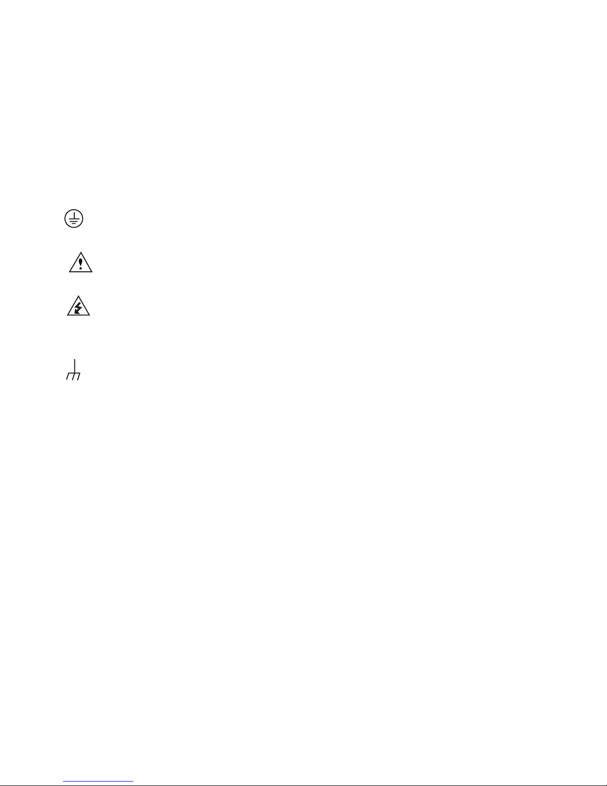
If a screw is present, connect it to safety earth ground using
the wire recommended in the user documentation.
The
should refer to the operating instructions located in the manual.
The
measure 1000 volts or more, including the combined effect of
normal and common mode voltages. Use standard safety
precautions to avoid personal contact with these voltages.
The
frame.
The WARNING heading in a manual explains dangers that
might result in personal injury or death. Always read the
symbol on an instrument indicates that the user
symbol on an instrument shows that it can source or
symbol indicates a connection terminal to the equipment
associated information very carefully before performing the
indicated procedure.
The CAUTION heading in a manual explains hazards that could
damage the instrument. Such damage may invalidate the
warranty.
Instrumentation and accessories shall not be connected to
humans.
Before performing any maintenance, disconnect the line cord and
all test cables.
To maintain protection from electric shock and fire, replacement
components in mains circuits – including the power transformer,
test leads, and input jacks – must be purchased from Keithley
Instruments. Standard fuses with applicable national safety
approvals may be used if the rating and type are the same. Other
components that are not safety-related may be purchased from
other suppliers as long as they are equivalent to the original
component. (Note that selected parts should be purchased only
through Keithley Instruments to maintain accuracy and
functionality of the product.) If you are unsure about the
applicability of a replacement component, call a Keithley
Instruments office for information.
To clean an instrument, use a damp cloth or mild, water based
cleaner. Clean the exterior of the instrument only. Do not apply
cleaner directly to the instrument or allow liquids to enter or spill
on the instrument. Products that consist of a circuit board with no
case or chassis (e.g., data acquisition board for installation into a
computer) should never require cleaning if handled according to
instructions. If the board becomes contaminated and operation is
affected, the board should be returned to the factory for proper
cleaning/servicing.
Page 9

2910-VSG Vector Signal Generator Quick Start Guide
2910-903-01 Rev. A / February 2006
Table of Contents
1 INSTALLING THE SYSTEM............................................................................................................................................ 1
Unpacking and inspecting the system ........................................................................................................................... 2
Inspection for damage.....................................................................................................................................................2
Shipment contents...........................................................................................................................................................2
Repacking for return shipment........................................................................................................................................ 2
Becoming familiar with the instrument...........................................................................................................................3
Figure 1-1. Front panel features ..................................................................................................................................... 3
Figure 1-2. Rear panel features......................................................................................................................................4
Figure 1-3. Instrument screen......................................................................................................................................... 5
Locating the instrument in the proper environment.....................................................................................................6
Installing the instrument in a rack...................................................................................................................................6
Powering the Model 2910.................................................................................................................................................. 7
Line power receptacle ..................................................................................................................................................... 7
Replacing a fuse..............................................................................................................................................................8
Connecting system components..................................................................................................................................... 9
Figure 1-4. Back panel view, Instrument connectors, and system connections...........................................................9
GPIB connections..........................................................................................................................................................10
LAN (Ethernet) connections.......................................................................................................................................... 10
USB connections ...........................................................................................................................................................10
Verifying digital modulation licenses ........................................................................................................................... 11
Purchasing modulation licenses ...................................................................................................................................11
Configuring the system for remote control or network .............................................................................................12
GPIB interface configuration ......................................................................................................................................... 12
LAN (Ethernet) interface configuration ......................................................................................................................... 13
USB configuration.......................................................................................................................................................... 17
2 GENERATING SIGNALS..............................................................................................................................................18
Setting up a basic signal with various input devices................................................................................................. 19
Set up a carrier frequency.............................................................................................................................................19
Set up the RF power level.............................................................................................................................................20
Save and recall the instrument setup ........................................................................................................................... 21
Setting up a frequency and power sweep .................................................................................................................... 21
Loading a digital modulation waveform ........................................................................................................................ 21
Getting information from Help .......................................................................................................................................22
Help from the Front panel .............................................................................................................................................22
Help from the CD-ROM .................................................................................................................................................22
Page 10

2910-VSG Vector Signal Generator Quick Start Guide
[This page left blank intentionally]
Page 11

2910-VSG Vector Signal Generator Quick Start Guide
2910-903-01 Rev. A / February 2006
1
Section 1
Installing the System
____________________________________________________________________________
Section 1 Topic List
Unpacking and checking the shipment contents
Inspection for damage
Shipment contents
Repacking for return shipment
Becoming familiar with the instrument
Front panel features
Rear panel features
Instrument screen
Locating the instrument in the proper environment
Installing the instrument in a rack
Powering the Model 2910
Replacing a fuse
Connecting system components
GPIB Connections
LAN (Ethernet) Connections
USB Connections
Verifying digital modulation licenses
Purchasing modulation licenses
Configuring the system for remote control or network
GPIB Interface configuration
LAN (Ethernet) Interface configuration
USB Interface configuration
Page 12

2910-VSG Vector Signal Generator Quick Start Guide
2910-903-01 Rev. A / February 2006
2
Unpacking and inspecting the system
Inspection for damage
After unpacking the Model 2910, carefully inspect the unit for any shipping damage. Report any
damage to the shipping agent immediately, as such damage is not covered by the warranty.
Shipment contents
The following items are included with every Model 2910 order:
• CD-ROM with software, drivers, and 2910-VSG help
• Power line cord
• Safety standard card
• Quick start guide
• Calibration certificate
One of the following models:
• Model 2910-F Front RF output with bench-top bumpers and handles
• Model 2910-R Rear RF output with bench-top bumpers and handles
• Model 2910-FRK Front RF output with rack-mount kit
• Model 2910-RRK Rear RF output with rack-mount kit
The following items are options than can be ordered for the Model 2910:
• Model 2910-GSM GSM/GPRS/EDGE Signal Generation Personality
• Model 2910-CDMA2000 CDMAOne/2000 Signal Generator Personality
• Model 2910-WCDMA W-CDMA Signal Generator Personality
• Model 2910-LPN Low-Phase Noise
• Model 2910-ARB 64 M-Sample Arbitrary Waveform Generator (ARB)
• Model 2910-ADAPTER-KIT RF Cables and RF connector Adapters
Type-N Male to Type-N Male cable (quantity 2, length 1M)
SMB Male to SMB Male cable (quantity 2, length 1M)
SMB Male to SMB Male cable (quantity 2, length 0.3M)
SMB Male to BNC Male cable (quantity 4, length 1M)
BNC Male to BNC Male cable (quantity 2, length 1M)
Type-N Male to SMA Female adapter (quantity 2)
USB Host to USB Device cable (quantity 1, length 1M)
Carry case (quantity 1)
• Model 2910-DCBLOCK External DC Block
• Model 2910-RMK Rack-mount Kit with flanges
• Model 2910-BENCH-KIT Bench-top Kit with bumpers and handles
• Factory Calibration Report of Instrument Calibration Data
Repacking for return shipment
Should it become necessary to return the Model 2910 for repair, carefully pack the entire unit in its
original packing carton or the equivalent, and perform the following steps:
• Contact Keithley to get a Return Material Authorization (RMA). You can contact Keithley
through your local Keithley representative, or by calling the Keithley factory at 1-888-534-8453
(1-888-KEITHLEY), or through the Keithley Web page at www.keithley.com.
• On the shipping label, write ATTENTION REPAIR DEPARTMENT, and the RMA number.
Warranty and contact information is located at the front of this manual.
Page 13
2910-VSG Vector Signal Generator Quick Start Guide
2910-903-01 Rev. A / February 2006
3
Becoming familiar with the instrument
WARNING:
The safe procedure to power-up the Model 2910 is provided in
“Powering the 2910.” Do not turn on the Model 2910 until you have
reviewed that information.
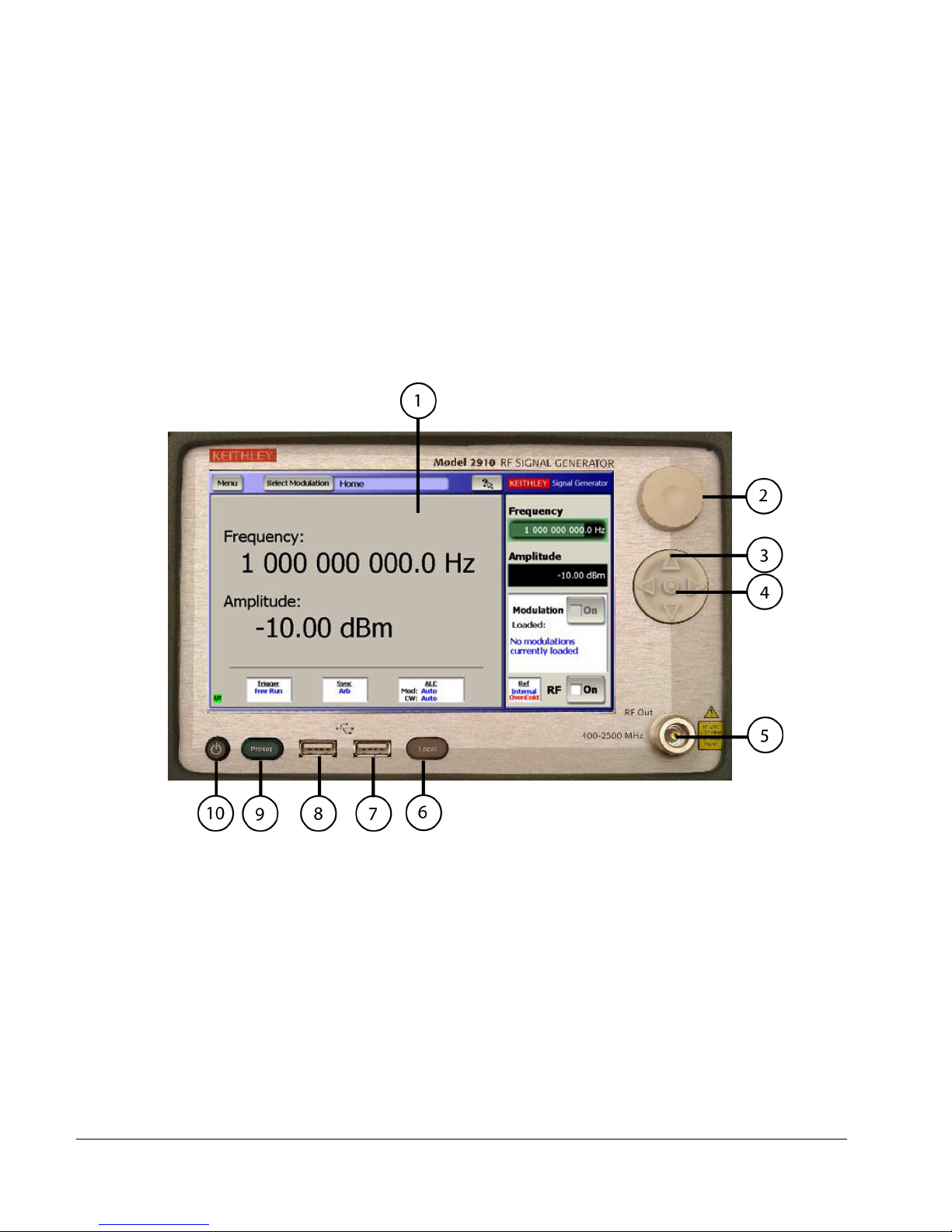
Figure 1-1.
Front panel features
1.
Display/touch screen — Displays state of instrument, allows input of settings, and is the primary mechanism
for entering data.
2.
Rotary knob — Changes the value of the selected numeric parameter.
3.
Puck/arrow keys — Changes the value of the selected numeric parameter incrementally or in a user-defined
step.
4.
Puck center button — Brings up the on-screen numeric entry keypad.
5.
RF output connector — Outputs the RF signal from instruments that have a front Type-N RF output (Models
2910-F and 2910-FRK).
6.
Local button — Switches instrument to front panel control after remote use.
7.
USB port — Connects to USB devices: mouse, keyboard, or USB flash drives.
8.
USB port — Connects to USB devices: mouse, keyboard, or USB flash drives.
9.
Preset button — Resets the instrument to the factory default-state settings.
10.
Power button — Switches the instrument power off and on.
Page 14

2910-VSG Vector Signal Generator Quick Start Guide
2910-903-01 Rev. A / February 2006
4
Figure 1-2.
Rear panel features
1.
Power inlet/switch, fuse module — Connects the instrument to AC power.
2.
RF OUT — Outputs the RF signal from instruments that have a rear Type-N RF output (Models 2910-R and
2910-RRK).
3.
VGA OUT — Connects the instrument display to an external monitor.
4.
Digital I/O — Outputs four programmable TTL signals.
5.
USB (from host) — Connects to a USB port on a computer. The computer then remotely controls the
instrument.
6.
USB (to device) — Connects to a USB device: mouse, keyboard, or flash drive.
7.
GPIB connector — Connects to GPIB control bus for remote operation.
8.
LAN — Connects to an Ethernet network for remote operation.
9.
REF OUT — Provides a frequency reference to synchronize other instruments (10 MHz).
10.
REF IN — Synchronizes the internal frequency reference to an external frequency reference (programmable
from 1 MHz to 20 MHz in 10-Hz increments).
11.
EVEN SEC OUT — Provides an even second clock to synchronize other instruments.
12.
EVEN SEC IN — Synchronizes the internal frequency reference to an even-second clock.
13.
SYNC OUT — Provides a signal for synchronizing events. It is often used in conjunction with the trigger input
signal to notify another device that the requested event has been performed.
14.
TRIG IN — Accepts a trigger from an external device to initiate an event in the 2910.
15.
Q-IN — Accepts an external signal to directly drive the Q-input of the I/Q modulator.
16.
I-IN — Accepts an external signal to directly drive the I-input of the I/Q modulator.
Page 15
2910-VSG Vector Signal Generator Quick Start Guide
2910-903-01 Rev. A / February 2006
5
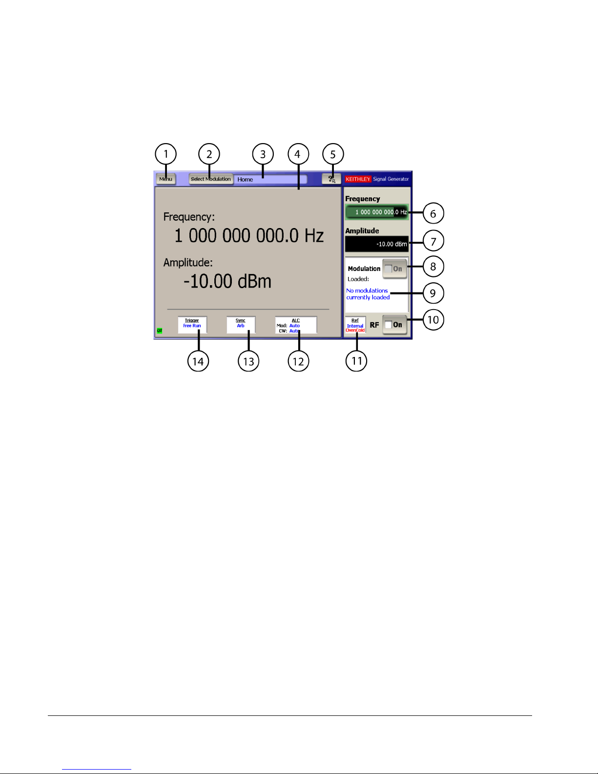
Figure 1-3.
Instrument screen
1.
Menu — Displays a drop-down menu that allows you to choose from File, Settings, Utility, and Help.
2.
Select Modulation — Displays a drop-down menu that allows you to choose from the various modulation
formats.
3.
Modulation Screen Display — Indicates the modulation personality that is displayed in the Modulation
Personality Window.
4.
Modulation Personality Display Window — Displays the modulation format window that allows waveform
editing and control.
5.
What’s This Help — Displays help information for the selected item.
6.
Frequency field — Shows the frequency setting. Select to edit the value.
7.
Amplitude field — Shows the RF power level. Select to edit the value.
8.
Modulation state — Switches the modulation on and off.
9.
Loaded modulation — Shows the modulation waveform currently loaded and output from the RF Output.
10.
RF state — Switches the RF output on and off.
11.
Ref state — Shows the frequency reference source. Select to edit the setting.
12.
ALC state — Shows the ALC setting. Select to edit the setting.
13.
Sync state — Shows the sync out setting. Select to edit the setting.
14.
Trigger state — Shows the trigger setting. Select to edit the setting.
Page 16

2910-VSG Vector Signal Generator Quick Start Guide
2910-903-01 Rev. A / February 2006
6
Locating the instrument in the proper environment
Locate the Model 2910 such that it will operate within the following ambient temperature and humidity
limits. (Refer to the instrument specifications for the complete set of environmental limits.)
• Temperature: +15° to +40°C (+23°C is optimal)
• Relative humidity: 5% to 80%, non-condensing
NOTE:
Accuracy specifications are based on operation at 23° ±5°C and between 5%
and 60% relative humidity. See the product specifications for derating factors
outside these ranges. Air-conditioned environments are highly
recommended.
CAUTION:
To avoid over-heating, operate the unit only in an area with proper
ventilation. Allow at least eight inches of clearance at the back of
the instrument to assure sufficient airflow, and adhere to the
following:
• Operate the unit in a clean, dust-free environment.
• Keep the rear exhaust vent free of any obstructions. Even
partial blockage may impair proper cooling. Also keep at least
one vent at the front of the instrument free of obstruction.
• Allow at least 1U of space at the top and bottom of the
instrument.
• Make sure there is adequate airflow around at least one side of
the instrument. Adequate airflow ensures that air temperatures
around the instrument remain within specified limits under all
operating conditions.
• To ensure proper cooling in rack environments with only
convection cooling, position the hottest equipment at the top of
the rack. Place precision equipment, such as the Model 2910, as
low as possible in the rack, where temperatures are the coolest.
Add spacer panels below the unit to help ensure adequate
airflow.
Installing the instrument in a rack
If you have Model 2910-RMK Rack-mount Kit with flanges, refer to the document that accompanied
the kit for installation instructions. Perform the rack mounting kit installation now.
Page 17
2910-VSG Vector Signal Generator Quick Start Guide
2910-903-01 Rev. A / February 2006
7
Powering the Model 2910
The Model 2910 operates within the following ranges:
• Line voltage of 100 to 240 VAC
• Frequency of 50 or 60 Hz.
Connect and power the Model 2910 as follows:
1. Check to be sure the operating voltage in your area is compatible with the Model 2910.
2. Operate the Model 2910 from a dedicated power source to avoid possible problems caused by
electrical transients or line voltage fluctuations.
CAUTION:
Operating the instrument on an incorrect line voltage may cause
damage, possibly voiding the warranty.
3. Before plugging in the power cord, make sure the rear panel power switch is OFF (O).
4. Connect the female end of the supplied power cord to the AC receptacle on the rear panel.
WARNING:
Use only the supplied, grounded line cord, or the equivalent, to
assure proper safety grounding.
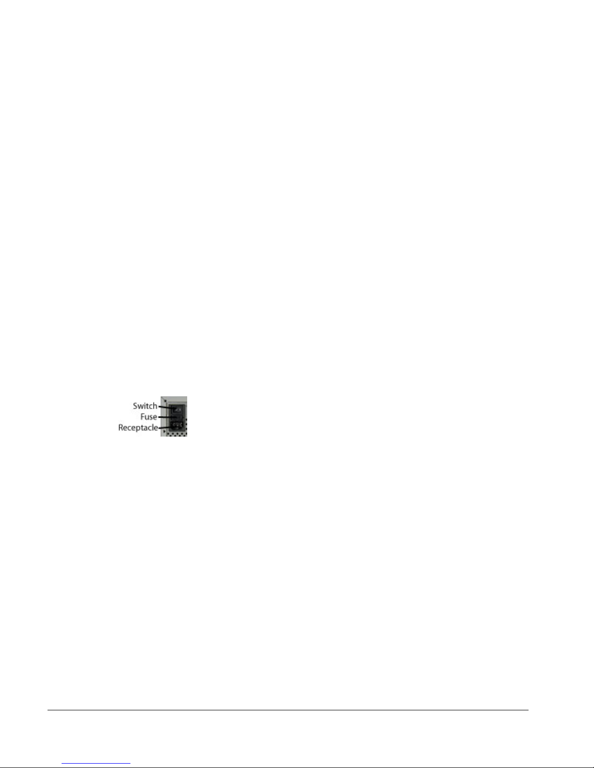
Line power receptacle
5. Connect the other end of the supplied line cord to a grounded AC line power receptacle.
WARNING:
The power cord supplied with the unit contains a separate ground
for use with grounded outlets. When proper connections are made,
the instrument chassis is connected to power line ground through
the ground wire in the power cord. Failure to use a grounded outlet
may result in personal injury or death due to electric shock.
6. Switch the rear panel power switch to the ON ( | ) position. The front panel power button should
have an amber illumination.
7. Switch the instrument on by pushing the front panel power button. The power button should
now have a green illumination. The 2910-VSG performs a series of self-tests. If it detects a
failure, the unit displays an error message.
NOTE:
If you notice that the power button is not illuminated or the 2910 seems
completely unresponsive after three minutes, you may need to change the
fuse. In this case, refer to “Replacing a fuse.”
NOTE:
If a problem develops, return the Model 2910 to Keithley Instruments, Inc. for
repair. Refer to “Repacking for return shipment” for more information on
returning the Model 2910 to the factory.
Page 18

2910-VSG Vector Signal Generator Quick Start Guide
2910-903-01 Rev. A / February 2006
8
8. If the 2910 passes the self tests, it automatically boots the system software and displays the
start-up screen.
9. Warm-up the instrument. The Model 2910 can be used immediately after being switched ON.
However, to achieve specified performance, warm-up for at least 30 minutes.
Replacing a fuse
If the line fuse needs to be replaced, perform the following steps:
WARNING:
Make sure the instrument is disconnected from the AC line and
other equipment before changing line fuse.
1. Using a small flat-blade screwdriver, push the retaining clip toward the center of the module to
release the fuse holder assembly.
2. Pull the fuse holder out of the power module.
3. Remove blown fuses and replace with a similar 2.0 Amp, 250 VAC, 5x20 mm slow-blow fuse.
CAUTION:
For continued protection against fire or instrument damage, only
replace fuses with the type and rating listed. If the instrument
repeatedly blows fuses, return the unit to Keithley Instruments.
Page 19
2910-VSG Vector Signal Generator Quick Start Guide
2910-903-01 Rev. A / February 2006
9
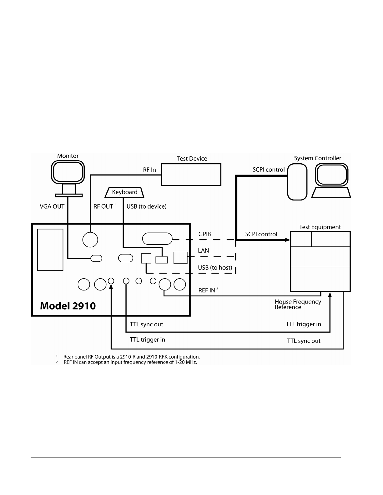
Connecting system components
The following diagram shows how typical system components are installed.
Figure 1-4.
Back panel view, instrument connectors, and
system connections
Page 20

2910-VSG Vector Signal Generator Quick Start Guide
2910-903-01 Rev. A / February 2006
10
GPIB connections
• Connect a GPIB bus cable equipped with standard IEEE-488 connectors to the Model 2910
back panel IEEE-488 connector.
• Connect many instruments to one instrument, using parallel connections that stack the
connectors as shown in the following graphic.
NOTE:
Two screws are located on each connector to ensure that connections
remain secure. Present standards call for metric threads, which are identified
with dark-colored screws. Earlier versions have different screws, which are
silver-colored. Do not use these silver-colored types of connectors on the
Model 2910; it is designed for metric threads.
NOTE:
To minimize interference caused by electromagnetic radiation, use only
shielded IEEE-488 cables. Available shielded cables from Keithley are
Models 7007-1 and 7007-2.
LAN (Ethernet) connections
• Connect the Model 2910 back panel LAN connector to an existing site network through a
router, switch, or hub. Use a standard patch cable for this connection.
Or
• Connect the Model 2910 back panel LAN connector directly to a computer. You must use a
crossover cable for this connection to ensure that the computer transmit connections are input
to the 2910 receive connections and vice versa. (Model CA-180-3A crossover cable is
available for ordering from Keithley.)
NOTE:
The Ethernet crossover cable can be up to 100 meters in length.
USB connections
• Connect a computer controller to the Model 2910 back panel USB (FROM HOST) connector.
• Connect all other USB devices to the Model 2910 back panel USB (TO DEVICE) connector or
to the two USB connectors on the front panel.
Page 21

2910-VSG Vector Signal Generator Quick Start Guide
2910-903-01 Rev. A / February 2006
11
Verifying digital modulation licenses
The Model 2910 requires a license file to access the digital modulation waveforms in the source. To
view the current licenses select Menu > Utilities > Licensing.
You can purchase the following licenses for your instrument:
• License Option 2910-ARB (64 Mega-Sample Arbitrary Waveform Generator)
• License Option 2910-GSM (GSM Signal Generation Personality)
• License Option 2910-CDMA2000 (CDMA2000 Signal Generation Personality)
• License Option 2910-WCDMA (WCDMA Signal Generation Personality)
NOTE:
Each instrument must have an arbitrary waveform generator license (2910ARB) for the other digital modulation licenses to operate.
Purchasing modulation licenses
You can purchase modulation license files at the time of ordering your instrument or at any time after
you have received your instrument.
Complete the purchasing information in the license certificate (RF Product Software Option Certificate)
that was shipped with the 2910. Contact your Keithley Instruments sales representative or use one of
the following numbers/addresses to receive a replacement license certificate.
• America: 888-KEITHLEY (888-534-8453)
• (440) 248-0400
• info@keithley.com
• www.keithley.com
Page 22

2910-VSG Vector Signal Generator Quick Start Guide
2910-903-01 Rev. A / February 2006
12
Configuring the system for remote control or network
After adding supported external instruments in the previous section “Connecting system components”
— external GPIB instruments, LAN (Ethernet ) network, and computers — you must properly configure
the system so that the Model 2910 can operate correctly in one of the following system configurations.
• GPIB configuration
• Ethernet configuration
• USB configuration
GPIB interface configuration
To avoid communication conflicts over the bus, each device in a GPIB system must have a unique
primary address. The Model 2910 is shipped from the factory with the primary address set to 12.
If you want to verify the GPIB address or change it, perform the following steps:
1. Select Menu > Utilities > GPIB Address.
2. Use the front panel knob to change the GPIB address, if necessary.
3. Select Close.
Verify remote control over GPIB
If you want to verify communication between a computer and the 2910 instrument over the GPIB,
install the KI 2910 Communicator application that allows you to test SCPI communication of your
instrument. Perform the following steps:
1. Make sure you have a GPIB cable connected between the instrument back panel IEEE-488
connector and the computer GPIB board connector.
2. Insert the 2910 CD-ROM in the computer drive.
3. After the CD-ROM launches, click Applications Info > KI 2910 Communicator to download
the application installation program.
4. Click the downloaded setup.exe file to install the application on your computer.
5. On your computer desktop, click the KI 2910 Communicator icon to start the application.
6. In the KI 2910 Communicator home screen, click Setup Interface.
7. In the Configure VISA Interface dialog, select the GPIB tab.
8. Set the values for the following GPIB settings:
GPIB board # (Leave this set to zero, unless you have more than one GPIB interface
board in your computer.)
GPIB primary address
9. Click OK.
10. Click Send Command to send the command *IDN? that is shown in the Command: box.
Page 23

2910-VSG Vector Signal Generator Quick Start Guide
2910-903-01 Rev. A / February 2006
13
11. You should see the instrument identification information in the Response: field.
12. Continue sending any other SCPI commands of interest. See the Model 2910 Help for a
complete list of compatible SCPI commands.
LAN (Ethernet) interface configuration
It is necessary to assign an IP address to the signal generator. The IP address is a persistent state; it
is not affected by an instrument preset or a power cycle. The following procedures assume that you
have connected the equipment as instructed in “Connecting system components.”
The appropriate procedure depends on the 2910 connection configuration.
• Existing site network connection
Or
• Direct connection to a computer
NOTE:
This procedure assumes that the instrument is connected to the LAN using a
CAT 5e or better patch cable.
Existing site network configuration
Contact your I.T. administrator to receive direction on the preferred method of assigning IP addresses:
either a static IP address assignment or a DHCP address assignment.
Static IP address assignment
1. From the 2910, select Menu > Utilities > Ethernet Settings.
2. Select the IP Address tab.
3. Enter an IP address:
a. Select Specify an IP address.
b. Select the IP Address field or the keyboard button next to it.
c. Repeatedly select the _ (backspace) button to clear the current IP address.
d. Select the desired IP address and then select Enter.
4. Enter a subnet mask:
a. Select the Subnet Mask field or the keyboard button next to it.
b. Repeatedly select the _ (backspace) button to clear the current subnet mask.
c. Select the desired subnet mask and then select Enter.
5. Set the default gateway and DNS per your I.T. administrator’s recommendations.
6. Set the following values per your I.T. administrator’s recommendations (You can leave the
values blank if there are no recommendations.):
Default gateway
Primary DNS
Primary WINS
Page 24

2910-VSG Vector Signal Generator Quick Start Guide
2910-903-01 Rev. A / February 2006
14
7. Select the Apply button.
8. Select Close to close the dialog.
NOTE:
Make sure that the combination of 2910 IP address and subnet mask is
within the range of directly addressable IP addresses of the computer.
For example:
Computer IP address: 192.168.1.50
Computer subnet mask: 255.255.255.0
2910 IP address: 192.168.1.51
2910 subnet mask: 255.255.255.0
DHCP address assignment
If a DHCP server is on the LAN, you can choose to have a DHCP automatically assign an IP address.
1. From the 2910, select Menu > Utilities > Ethernet Settings.
2. Select the IP Address tab.
3. Select Obtain an IP address via DHCP.
4. Select the Apply button.
5. This configures the signal generator as a DHCP client. In DHCP mode, the signal generator
requests a new IP address from the DHCP server. The assigned address appears in the IP
Address field.
6. Select Close to close the dialog.
Direct connection configuration
Assigning a static IP address is the preferred method of assigning an IP address for a configuration
that has the 2910 directly connected to the computer. Optionally, you can use the DHCP method,
which results in a Link Local Address (LLA) being assigned to the 2910.
Static IP address assignment
1. From the 2910, select Menu > Utilities > Ethernet Settings.
Page 25

2910-VSG Vector Signal Generator Quick Start Guide
2910-903-01 Rev. A / February 2006
15
2. Select the IP Address tab.
3. Enter an IP address:
a. Select Specify an IP address.
b. Select the IP Address field or the keyboard button next to it.
c. Repeatedly select the _ (backspace) button to clear the current IP address.
d. Select the desired IP address and then select Enter.
4. Enter a subnet mask:
a. Select the Subnet Mask field or the keyboard button next to it.
b. Repeatedly select the _ (backspace) button to clear the current subnet mask.
c. Select the desired subnet mask and then select Enter.
5. Set the following values per your I.T. administrator’s recommendations (You can leave the
values blank if there are no recommendations.):
Default gateway
Primary DNS
Primary WINS
6. Select the Apply button.
7. Select Close to close the dialog.
NOTE:
Make sure that the combination of 2910 IP address and subnet mask is
within the range of directly addressable IP addresses of the computer.
For example:
Computer IP address: 192.168.1.50
Computer subnet mask: 255.255.255.0
2910 IP address: 192.168.1.51
2910 subnet mask: 255.255.255.0
DHCP address assignment
Optionally, you can use the DHCP method to assign an IP address. Since there is no DHCP server in
a configuration that directly connects the 2910 to a computer, the instrument will timeout and then
automatically assign itself a Link Local Address (LLA). This process takes 60-90 seconds.
1. From the 2910, select Menu > Utilities > Ethernet Settings.
2. Select the IP Address tab.
3. Select Obtain an IP address via DHCP.
4. Select the Apply button. This attempts to configure the signal generator as a DHCP client.
5. Select Close to close the dialog.
6. When the LAN error indicator disappears (60-90 seconds), select Menu > Utilities > Ethernet
Settings. The LLA that was automatically assigned appears in the IP Address field.
7. Select Close to close the dialog.
Page 26

2910-VSG Vector Signal Generator Quick Start Guide
2910-903-01 Rev. A / February 2006
16
Verify remote control over LAN
If you want to verify communication between a computer and the 2910 instrument over the LAN, install
the KI 2910 Communicator application that allows you to test SCPI communication of your instrument.
Perform the following steps:
1. Set-up the equipment as shown in the previous procedure, “Connecting system components.”
2. Assign an IP address for the 2910 by following a procedure for one of the configurations
described in “LAN Interface configuration.”
3. Insert the 2910 CD-ROM in the computer drive.
4. When the CD-ROM launches, click Applications Info > KI 2910Communicator to download
the application installation program.
5. Click the downloaded setup.exe file to install the application on your computer.
6. On your computer desktop, click the KI 2910 Communicator icon to start the application.
7. In the KI 2910 Communicator home screen, click Setup Interface.
8. In the Configure VISA Interface dialog, select the LAN/TCPIP tab.
9. Set the values for the following settings, or the values displayed in the Ethernet dialog if DHCP
is used.
NIC # (Leave this set to zero, unless you have more than one NIC card installed in your
computer.)
TCPIP port # = 5025
TCPIP address = IP address that you assigned to the 2910
10. Click OK.
11. Click Send Command to send the *IDN? command that is in the Command: box.
12. You should see the instrument identification information in the Response: field.
13. Continue sending any other SCPI commands of interest. See the Model 2910 Help for a
complete list of compatible SCPI commands.
LAN Troubleshooting
The 2910 defaults to an Ethernet setting of “Auto-negotiation On” to detect the speed of the network
and set the instrument operation speed to match the network speed. If the auto-negotiation process
fails, the operation speed must be set manually.
NOTE:
If the instrument speed does not match the network speed, Autonegotiation On is the recommended setting.
1. Select Menu > Utilities > Ethernet Settings.
2. Select the Advanced tab.
3. Select the appropriate speed.
10 Mbps
100 Mbps
4. Select Apply.
5. To ensure that both the instrument and the network recognize the speed change, you may
need to disconnect and then reconnect the LAN cable.
Page 27

2910-VSG Vector Signal Generator Quick Start Guide
2910-903-01 Rev. A / February 2006
17
USB configuration
It is necessary to load a USB driver on to the computer that will be running the remote control
program. Although the 2910 CD-ROM will have a driver installed on it, the latest version of the USB
driver can be downloaded from the Keithley Website.
Installing USB driver from the CD-ROM
1. Insert the 2910 CD-ROM into the disk drive of the computer.
2. Follow the operating system instructions to load the USB driver.
Installing USB driver from the Keithley Website
1. With the computer connected to the internet, insert the 2910 CD-ROM into the computer disk
drive.
2. After the CD-ROM launches, click Online Updates to get to the Keithley Downloads Website,
www.keithley.com.
3. In the search area at the top right corner of the web page, select Downloads from the pulldown menu.
4. Type “drivers” in the text box to the right of the of the pull-down menu.
5. Select the search button to the right of the text box.
6. Scroll to the USB driver for the 2910 VSG.
7. Click the link to the USB driver for the 2910 VSG.
8. Download the 2910 USB driver from the website.
9. Click the driver setup file that you just downloaded.
Verify remote control over USB
If you want to verify communication between a computer and the 2910 instrument over the USB, install
the KI 2910 Communicator application that allows you to test SCPI communication of your instrument.
Perform the following steps:
1. Set up the equipment as shown in the previous procedure, “Connecting system components.”
2. Insert the 2910 CD-ROM in the computer drive and click Install KI 2910 Communicator to
download the application installation program.
3. Select Run to install the program on your computer.
4. Select the KI 2910 Communicator Icon that has been placed on the desktop.
5. In the KI 2910 Communicator home screen, click Setup Interface.
6. In the Configure VISA Interface dialog, select the USB tab and click Find USB Devices.
This will display a list of all 2910s connected via USB.
7. Select the list item that corresponds with the serial number of the instrument that you want to
communicate with, and then click OK.
8. Click Send Command to send the *IDN? command that is in the Command: box.
9. You should see the instrument identification information in the Response: field.
10. Continue sending any other SCPI commands of interest. See the Model 2910 Help for a
complete list of compatible SCPI commands.
Page 28

2910-VSG Vector Signal Generator Quick Start Guide
2910-903-01 Rev. A / February 2006
18
Section 2
Generating Signals
____________________________________________________________________________
Section 2 Topic List
Setting up a basic signal with various input devices
Set up a carrier frequency
Set up the RF power level
Save and recall the instrument setup
Setting up a frequency and power sweep
Loading a digital modulation waveform
Getting information from Help
Page 29

2910-VSG Vector Signal Generator Quick Start Guide
2910-903-01 Rev. A / February 2006
19
Setting up a basic signal with various input devices
This set of example procedures show you how to set up the frequency and power of a signal with the
following input devices:
Front panel puck
Numeric keypad
Front panel knob
Mouse
Set up a carrier frequency
With the front panel puck:
1. Select the Frequency field to activate it.
2. Press the left arrow on the puck to change the frequency step to 1 GHz.
3. Press the up arrow on the puck to change the frequency to 2 GHz.
4. Press the right arrow on the puck to change the frequency step to 0.01 GHz.
5. Press the up arrow to change the frequency to 2.01 GHz.
Page 30

2910-VSG Vector Signal Generator Quick Start Guide
2910-903-01 Rev. A / February 2006
20
With the instrument screen:
1. Select the Frequency field to activate it.
2. Bring up the instrument keypad, using one of the following methods:
Press the center button on the front panel puck.
Double-select the Frequency field.
3. Select a new frequency value of 400 MHz and then select Enter.
With the front panel knob:
1. Select the Frequency field to activate it.
2. Adjust the front panel knob to lower the frequency to the minimum value.
With an attached mouse:
1. Double-click the Frequency field to activate it and to display the instrument keypad.
2. On the displayed instrument keypad, click the keys to select a frequency value of 2500 MHz.
3. Use the mouse wheel and the click-and-drag action to explore how you can also edit the
frequency value. This method is similar to using the front panel knob and the left and right
arrows on the puck.
4. On the displayed instrument keypad, click Step Size tab.
5. Change the step size to 25 kHz. Now, when you use the up/down arrow keys on the puck, the
frequency will increment/decrement by 25 kHz.
Set up the RF power level
With the front panel puck:
1. Select the RF On button to switch on the RF output power.
2. Select the Amplitude field to activate it.
3. Press the left arrow on the front panel puck to change the step value to 10 dB.
4. Press the down arrow on the puck to change the power to –10 dBm.
5. Press the right arrow on the puck to change the power increment to 0.1 dB.
6. Press the down arrow on the puck to change the power to –10.2 dBm.
With the instrument screen:
1. Select the Amplitude field to activate it.
2. Bring up the instrument keypad, using one of the following methods:
Press the center button on the front panel puck.
Double-select the Amplitude field.
3. Select a new power value of –100 dBm and then select Enter.
With the front panel knob:
1. Select the Amplitude field to activate it.
2. Adjust the front panel knob to lower the RF output power to the minimum value.
With an attached mouse:
1. Double-click the Amplitude field to activate it and display the instrument keypad.
2. On the displayed instrument keypad, click the keys 10 dBm to select a power value.
3. Use the mouse wheel to set the power level to the maximum value.
Page 31

2910-VSG Vector Signal Generator Quick Start Guide
2910-903-01 Rev. A / February 2006
21
Save and recall the instrument setup
1. Select Menu > File > Save Setup.
2. Select the keyboard button located next to the File Name: field.
3. Select the letters to spell the file name and select Enter.
4. Select Save.
5. Press the Preset button to return the instrument to the default setting values.
6. Select Menu > File > Load Setup.
7. Select (highlight) the file that you just saved.
8. Select Load.
Setting up a frequency and power sweep
This example procedure shows you how to set up a frequency sweep and a power sweep from the
front panel interface.
1. Select the Preset button on the front panel.
2. Select Menu > Settings > Sweep.
3. Select the fields in the Sweep dialog and enter values using one of the following methods:
Adjust the front panel puck or knob to change the value.
Double-click a value field and enter a value from the keypad, followed by the correct
terminator.
4. Select the Start Frequency or Start Power field and enter a value. This is the frequency or
power setting of the first step in the sweep.
5. Select the Stop Frequency or Stop Power field and enter a value. This is the frequency or
power setting of the last step in the sweep.
6. Select the Number of steps field and enter a value. (The default is 201 and the maximum is
2000.) As the source sweeps the power or frequency range, it divides the range by this
number, resulting in the number of individual instrument settings that the instrument makes
when progressing through the sweep range.
7. Select the Dwell Time field and enter a value. (The default is 0 seconds.) This is the time the
instrument stays at the specific settings for each step in the sweep range.
8. Select the Sweep Now button in the Sweep dialog to start the sweep.
9. Select the Stop Sweep button in the Sweep dialog to stop the sweep.
NOTE:
The main status area shows the “Sweeping” indication in both the
Frequency and Amplitude fields.
Loading a digital modulation waveform
This example procedure shows you how to load a GSM / EDGE modulation waveform. See
“Verifying digital modulation licenses” for details.
1. Press instrument Preset.
2. Choose the Select Modulation button.
3. Select GSM / EDGE.
4. Select Waveform File.
5. Select Open.
Page 32

2910-VSG Vector Signal Generator Quick Start Guide
2910-903-01 Rev. A / February 2006
22
6. Navigate to file to open a waveform file. The file for a GSM / EDGE waveform will have a *.csv
notation indicating it is in a comma separated value format.
7. Select the waveform file.
8. Select Load, to place the file on the instrument display, ready for editing or applying to the RF
carrier signal.
9. Select Load to apply the waveform to the RF carrier signal. Notice that the waveform
modulation details appear below the Modulation On button.
10. Ensure both the RF On and Modulation On buttons are selected.
Getting information from Help
You can quickly access information that shows you how to set up and control output signals using the
2910 front panel interface and programming commands. You can access the 2910 Help from the front
panel menu and from the CD-ROM that was shipped with the instrument.
Help from the Front panel
To access the Help from the 2910 front panel, select Menu > Help > Help System….
Help from the CD-ROM
To access the Help from the 2910 CD-ROM:
1. Insert the CD-ROM into the computer.
2. If the computer is not set up for Auto-Run, double-click the CD drive in Windows Explorer.
3. When the CD launches, double-click the Open the 2910 System Help link.
4. Either Open the Help for immediate use or Save it to a computer file for later recall and use.
Page 33

Service Form
Model No. Serial No. Date
Name and Telephone No.
Company
List all control settings, describe problem and check boxes that apply to problem.
❏ Intermittent ❏ Analog output follows display ❏ Particular rang e or function bad; spec ify
❏ IEEE failure ❏ Obvious problem on power-up ❏ Batteries and fuses are OK
❏ Front panel operational ❏ All ranges or functions are bad ❏ Checked all cables
Display or output (check one)
❏ Drifts ❏ Unable to ze ro
❏ Unstable ❏ Will not read appli ed inpu t
❏ Overload
❏ Calibration only ❏ Certificate of calibration required
❏ Data required
(attach any additional she ets as necessary)
Show a block diagram of your measurement system including all instruments connected (whether power is turned on or not).
Also, describe signal source.
Where is the measurement being performed? (factory, controlled laboratory, out-of-doors, etc.)
What power line voltage is used? Ambient temperature? °F
Relative humidity? Other?
Any additional information. (If special modifications have been made by the user, please describe.)
Be sure to include your name and phone number on this service form.
Page 34

All Keithley trademarks and trade names are the property of Keithley Instruments, Inc.
All other trademarks and trade names are the property of their respective companies.
A GREATER MEASURE OF CONFIDENCE
Corporate Headquarters • 28775 Aurora Road • Cleveland, Ohio 44139 • 440-248-0400 • Fax: 440-248-6168 • 1-888-KEITHLEY (534-8453) • www.keithley.com
Specifications are subject to change without notice.
Keithley Instruments, Inc.
12/04
 Loading...