

Page 1

Model 2750
Multimeter/Switch System
User’s Manual
2750-900-01 Rev. F / August 2011
moc.yelhtiek.www
ECNEDIFNOC FO ERUSAEM RETAERG A
Page 2

Model 2750 Multimeter/Switch System
User’s Manual
2011, Keithley Instruments, Inc.
All rights reserved.
Cleveland, Ohio, U.S.A.
Document Number: 2750-900-01 Rev. F
Page 3

Page 4

Safety Precautions
04/09
The following safety precautions should be observed before using this product and any associated instrumentation.
Although some instruments and accessories would normally be used with non-hazardous voltages, there are
situations where hazardous conditions may be present.
This product is intended for use by qualified personnel who recognize shock hazards and are familiar with the safety
precautions required to avoid possible injury. Read and follow all installation, operation, and maintenance
information carefully before using the product. Refer to the user documentation for complete product specifications.
If the product is used in a manner not specified, the protection provided by the product warranty may be impaired.
The types of product users are:
Responsible body is the individual or group responsible for the use and maintenance of equipment, for ensuring
that the equipment is operated within its specifications and operating limits, and for ensuring that operators are
adequately trained.
Operators use the product for its intended function. They must be trained in electrical safety procedures and proper
use of the instrument. They must be protected from electric shock and contact with hazardous live circuits.
Maintenance personnel perform routine procedures on the product to keep it operating properly, for example,
setting the line voltage or replacing consumable materials. Maintenance procedures are described in the user
documentation. The procedures explicitly state if the operator may perform them. Otherwise, they should be
performed only by service personnel.
Service personnel are trained to work on live circuits, perform safe installations, and repair products. Only properly
trained service personnel may perform installation and service procedures.
Keithley Instruments products are designed for use with electrical signals that are rated Measurement Category I
and Measurement Category II, as described in the International Electrotechnical Commission (IEC) Standard IEC
60664. Most measurement, control, and data I/O signals are Measurement Category I and must not be directly
connected to mains voltage or to voltage sources with high transient over-voltages. Measurement Category II
connections require protection for high transient over-voltages often associated with local AC mains connections.
Assume all measurement, control, and data I/O connections are for connection to Category I sources unless
otherwise marked or described in the user documentation.
Exercise extreme caution when a shock hazard is present. Lethal voltage may be present on cable connector jacks
or test fixtures. The American National Standards Institute (ANSI) states that a shock hazard exists when voltage
levels greater than 30V RMS, 42.4V peak, or 60VDC are present. A good safety practice is to expect that hazardous
voltage is present in any unknown circuit before measuring.
Operators of this product must be protected from electric shock at all times. The responsible body must ensure that
operators are prevented access and/or insulated from every connection point. In some cases, connections must be
exposed to potential human contact. Product operators in these circumstances must be trained to protect
Page 5

themselves from the risk of electric shock. If the circuit is capable of operating at or above 1000V , no conductive part
!
of the circuit may be exposed.
Do not connect switching cards directly to unlimited power circuits. They are intended to be used with impedance-
limited sources. NEVER connect switching cards directly to AC mains. When connecting sources to switching cards,
install protective devices to limit fault current and voltage to the card.
Before operating an instrument, ensure that the line cord is connected to a properly-grounded power receptacle.
Inspect the connecting cables, test leads, and jumpers for possible wear, cracks, or breaks before each use.
When installing equipment where access to the main power cord is restricted, such as rack mounting, a separate
main input power disconnect device must be provided in close proximity to the equipment and within easy reach of
the operator.
For maximum safety, do not touch the product, test cables, or any other instruments while power is applied to the
circuit under test. ALWAYS remove power from the entire test system and discharge any capacitors before:
connecting or disconnecting cables or jumpers, installing or removing switching cards, or making internal changes,
such as installing or removing jumpers.
Do not touch any object that could provide a current path to the common side of the circuit under test or power line
(earth) ground. Always make measurements with dry hands while standing on a dry, insulated surface capable of
withstanding the voltage being measured.
The instrument and accessories must be used in accordance with its specifications and operating instructions, or
the safety of the equipment may be impaired.
Do not exceed the maximum signal levels of the instruments and accessories, as defined in the specifications and
operating information, and as shown on the instrument or test fixture panels, or switching card.
When fuses are used in a product, replace with the same type and rating for continued protection against fire hazard.
Chassis connections must only be used as shield connections for measuring circuits, NOT as safety earth ground
connections.
If you are using a test fixture, keep the lid closed while power is applied to the device under test. Safe operation
requires the use of a lid interlock.
If a screw is present, connect it to safety earth ground using the wire recommended in the user documentation.
The symbol on an instrument means caution, risk of danger. The user should refer to the operating instructions
located in the user documenta ti on in all case s wh ere th e symb ol is ma rked on the instrument.
The symbol on an instrument means caution, risk of danger. Use standard safety precautions to avoid personal
contact with these voltages.
The symbol on an instrument shows that the surface may be hot. Avoid personal contact to prevent burns.
The symbol indicates a connection terminal to the equipment frame.
If this symbol is on a product, it indicates that mercury is present in the display lamp. Please note that the lamp
must be properly disposed of according to federal, state, and local laws.
Page 6

The WARNING heading in the user documentation explains dangers that might result in personal injury or death.
Always read the associated information very carefully before performing the indicated procedure.
The CAUTION heading in the user documentation explains hazards that could damage the instrument. Such
damage may invalidate the warranty.
Instrumentation and accessories shall not be connected to humans.
Before performing any maintenance, disconnect the line cord and all test cables.
To maintain protection from electric shock a nd fire, replacement components in mains circuits - including the power
transformer, test leads, and input jacks - must be purchased from Keithley Instruments. Standard fuses with
applicable national safety approvals may be used if the rating and type are the same. Other components that are
not safety-related may be purchased from other suppliers as long as they are equivalent to the original component
(note that selected parts should be purchased only through Keithley Instruments to maintain accuracy and
functionality of the product). If you are unsure about the applicability of a replacement component, call a Keithley
Instruments office for information.
T o clean an instrument, use a damp cloth or mild, water-based cleaner . Clean the exterior of the instrument only . Do
not apply cleaner directly to the instrument or allow liquids to enter or spill on the instrument. Products that consist
of a circuit board with no case or chassis (e.g., a data acquisition board for installation into a computer) should never
require cleaning if handled according to instructions. If the board becomes contaminated and operation is affected,
the board should be returned to the factory for proper cleaning/servicing.
Page 7

Page 8

Table of Contents
1 Getting Started
General information ................................................................................. 1-2
Contact information .......................................................................... 1-2
Safety symbols and terms .................................................. ............... 1-2
Inspection .......................................................................................... 1-3
Options and accessories .................................................................... 1-3
Model 2750 features ................................... .................................. ............ 1-5
Plug-in switching modules ....................................................................... 1-6
Pseudocards ...................................................................................... 1-8
Identifying installed switching modules ........................................... 1-8
Front and rear panel familiarization ......................................................... 1-9
Front panel summary ........................................................................ 1-9
Rear panel summary ....................................................................... 1-12
Rack mounting ....................................................................................... 1-13
Power-up ................................................................................................ 1-14
Line power connection .................................................................... 1-14
Line frequency ................................................................................ 1-15
Setting line voltage and replacing fuse ........................................... 1-15
Power-up sequence ......................................................................... 1-16
Keyclick .......................................................................................... 1-16
Display ................................................................................................... 1-17
Status and error messages ............................................................... 1-17
Remote programming — display .................................................... 1-17
Defaults and user setups ......................................................................... 1-19
Saving and restoring setups ............................................................ 1-20
Remote programming — default and user setups ........................... 1-24
Remote programming information ......................................................... 1-25
Quick start exercises .............................................................................. 1-25
Basic DMM measurements — front panel inputs .......................... 1-26
Closing and opening channels — system channel operation .......... 1-28
Simple scanning .............................................................................. 1-31
Trigger and return readings — remote programming ..................... 1-34
2 Closing and Opening Switching Module Channels
Close/open overview ................................................................................ 2-2
Switching module installation and connections ....................................... 2-3
Module installation ........................................................................... 2-3
Connections ...................................................................................... 2-5
Pseudocards ...................................................................................... 2-6
Channel assignments ................................................................................ 2-6
System channel operation ........................................................................ 2-7
Page 9

2-wire functions ........................................ ......................................... 2-8
4-wire functions (paired channels) ................................................... . 2-8
Controlling the system channel ......................................................... 2-9
Non-amp and non-measure switching modules .............................. 2-13
Multiple channel operation .................................... ................................. 2-15
Controlling multiple channels ......................................................... 2-17
Multiple channel operation anomalies ............................................ 2-21
Dual independent multiplexers ........................................................ 2-23
Identifying installed modules and viewing closed c hannels .................. 2-28
CARD menu ............................................. .................................. ..... 2-28
Switching module queries (remote operation) ................................ 2-30
Relay closure count ................................................................................ 2-32
Reading relay closure count ............................................................ 2-33
Setting count update interval ........................................................... 2-33
Model 7700 switching module .......................................................... ... .. 2-34
Switching module capabilities ........................................................ 2-34
Schematic diagram ................................ .......................................... 2-35
3 Basic DMM Operation
DMM measurement capabilities ............................................................... 3-2
High energy circuit safety precautions ..................................................... 3-3
Performance considerations ...................................................................... 3-4
Warm-up ............................................................................................ 3-4
Autozero ............................................................................................ 3-4
LSYNC (line cycle synchronization) ................................................ 3-5
Remote programming — autozero and LSYNC ............................... 3-6
Channel list parameter (<clist>) ............................................................... 3-7
Voltage measurements (DCV and ACV) .................................................. 3-8
DCV input divider ............................................................................ . 3-8
Connections ....................................................................................... 3-8
Volts measurement procedure ......................................................... 3-11
Crest factor .............................. .................................. ...................... 3-12
Low level considerations ................................................................. 3-12
Current measurements (DCI and ACI) ................................................... 3-14
Connections ..................................................................................... 3-14
Amps measurement procedure ........................................................ 3-15
AMPS fuse replacement (front panel AMPS input) ........................ 3-16
Resistance measurements (Ω2 and Ω4) .................................................. 3-16
Connections ..................................................................................... 3-17
Standard resistance measurements .................................................. 3-19
Offset-compensated ohms ............................................................... 3-20
Dry circuit ohms (DRYCKT) .......................................................... 3-22
Temperature measurements .................................................................... 3-25
Thermocouples ................................................................................ 3-25
Page 10

Thermistors ..................................................................................... 3-27
4-wire RTDs .............................................................. ...................... 3-28
Connections .................................................................................... 3-28
Temperature measurement configuration ........................................ 3-34
Temperature measurement procedure ............................................. 3-37
Frequency and period measurements ..................................................... 3-38
Trigger level ................................................... ................................. 3-38
Gate time ......................................................................................... 3-38
Connections .................................................................................... 3-39
Frequency and period measurement procedure .............................. 3-40
Continuity testing ........................................................................... ........ 3-41
Connections .................................................................................... 3-41
Continuity testing procedure ........................................................... 3-42
Remote programming for basic measurements ...................................... 3-43
Basic measurement commands ....................................................... 3-43
Basic measurement programming examples .................................. 3-49
Measurement queries ............................................................................. 3-50
:FETCh? .......................................................................................... 3-50
:READ? ........................................................................................... 3-51
:MEASure[:<function>]? ................................................................ 3-51
[:SENSe[1]]:DATA:FRESh? ........................................................... 3-52
[:SENSe[1]]:DATA[:LATest]? ........................................................ 3-52
Examples ......................................................................................... 3-53
4 Range, Digits, Rate, Bandwidth, and Filter
Range ....................................................................................................... 4-2
Measurement ranges and maximum readings ................................... 4-2
Manual ranging ................................................................................. 4-2
Auto ranging ..................................................................................... 4-3
Scanning ............................................................................................ 4-3
Remote programming — range ........................................................ 4-4
Digits ........................................................................................................ 4-5
Scanning ............................................................................................ 4-5
Remote programming — digits ........................................................ 4-6
Rate and bandwidth .................................................................................. 4-8
Rate ................................................................................................... 4-8
Bandwidth ....................................................................................... 4-10
Scanning .......................................................................................... 4-10
Remote programming — rate and bandwidth ................................. 4-11
Filter ....................................................................................................... 4-14
Filter characteristics ........................................................................ 4-14
Remote programming — filter ........................................................ 4-19
5 Relative, Math, Ratio, ChannelAver age, and dB
Page 11

Relative ..................................................................................................... 5-2
Basic operation .................................................................................. 5-2
Remote programming — rel ............................................................. 5-4
Math .......................................................................................................... 5-8
mX+b ................................................................................................. 5-9
Percent ............................................................................................. 5-10
Reciprocal (1/X) .............................................................................. 5-11
Basic operation ................................................................................ 5-12
Remote programming — math ........................................................ 5-13
Ratio and channel average ..................................... ................................. 5-16
Basic operation ................................................................................ 5-17
Remote programming — ratio and channel average ....................... 5-19
dB ........................................................................................................... 5-21
Remote programming — dB ........................................................... 5-21
6Buffer
Buffer overview ........................................................................................ 6-2
Front panel buffer ..................................................................................... 6-2
Auto clear .......................................................................................... 6-2
Timestamps ....................................................................................... 6-3
Storing readings ................................................................................. 6-5
Recalling readings ............................................................................. 6-6
Buffer statistics .................................................................................. 6-7
Remote programming — buffer ......................... .................................. .... 6-8
Buffer commands .............................................................................. 6-8
Programming example .................................................................... 6-15
7 Scanning
Scanning fundamentals ............................................................................. 7-2
Channel assignments ......................................................................... 7-3
Sequential and non-sequential scans ................................................. 7-3
Scan process .............................................................. ... ..................... 7-3
Trigger models .................................................................................. 7-4
Scan configuration .................................................................................. 7-11
Scan reset ......................................................................................... 7-13
Simple scan ..................................................................................... 7-13
Advanced scan ................................................................................. 7-14
Setting delay .................................................................................... 7-17
Monitor channel .............................................................................. 7-18
Auto channel configuration ............................................................. 7-19
Saving setup .................................................................................... 7-20
Auto scan ......................................................................................... 7-20
Scan operation ............................................ ............................................ 7-21
Basic scan ........................................................................................ 7-21
Page 12

Manual/external trigger scan ........................................................... 7-22
Monitor scan (analog trigger) ......................................................... 7-23
Remote programming — scanning ........................................................ 7-25
Trigger model .......................................................... ........................ 7-25
Channel setup .................................................................................. 7-26
Buffer .............................................................................................. 7-26
Scanning commands ....................................................................... 7-26
Scanning programming example .................................................... 7-31
Scanning examples ................................................................................. 7-32
External trigger scan ....................................................................... 7-32
Monitor scan ................................................................................... 7-35
8 T riggering
Trigger model ................................................................................. .......... 8-2
Idle .................................................................................................... 8-2
Control source and event detection ................................................... 8-3
Delay (auto or manual) ..................................................................... 8-3
Device action .................................................................................... 8-5
Output trigger .......................................................... .......................... 8-5
External triggering ................................................................................... 8-6
Digital I/O ......................................................... ................................ 8-6
External trigger ................................................................................. 8-7
Voltmeter complete ........................................................................... 8-7
External triggering example .............................................................. 8-8
External triggering with BNC connections ..................................... 8-11
Remote programming — triggering ....................................................... 8-12
Trigger model (remote operation) .............................................. ..... 8-12
Trigger model operation ......................................................... ........ 8-15
Triggering commands ............................................................. ........ 8-16
Programming example .................................................................... 8-17
9 Limits and Digital I/O
Limits ....................................................................................................... 9-2
Scanning ............................................................................................ 9-4
Basic limits operation ....................................................................... 9-4
Digital I/O ................................................................................................ 9-5
Digital input (trigger link input) ....................................................... 9-5
Digital outputs .......................................... ......................................... 9-6
Setting digital output ....................................................................... 9-11
Scanning .......................................................................................... 9-12
Remote programing — limits and digital output ................................... 9-13
Limits and digital output commands .............................................. 9-13
Limits and digital outputs programming example .......................... 9-15
Application — sorting resistors ............................................................. 9-16
Page 13

Limits .............................................................................................. 9-16
Digital outputs ................................................................................. 9-18
10 Remote Operations
Operation enhancements ........................................................................ 10-2
Pseudocards ..................................................................................... 10-2
Autozero .......................................................................................... 10-2
dB calculation .................................................................................. 10-2
Separate function setups .................................................................. 10-3
DCV input divider ........................................................................... 10-3
Multiple channel operation .............................................. ................ 10-3
GPIB setup .............................................................................................. 10-4
GPIB standards ................................................................................ 10-4
Selecting GPIB and setting primary address ................................... 10-4
GPIB connections ............................................................................ 10-5
General bus commands ........................................................................... 10-7
REN (remote enable) ....................................................................... 10-8
IFC (interface clear) ........................................................................ 10-8
LLO (local lockout) ................................................ ......................... 10-8
GTL (go to local) ............................................................................. 10-8
DCL (device clear) .......................................................................... 10-9
SDC (selective device clear) ........................................................... 10-9
GET (group execute trigger) ........................................................... 10-9
SPE, SPD (serial polling) ................................................................ 10-9
Front panel GPIB operation .................................................................. 10-10
Error and status messages ............................................................. 10-10
GPIB status indicators ................................................................... 10-10
LOCAL key ................................................................................... 10-11
Programming syntax ............................................................................. 10-11
Command words ........................................................................... 10-11
Query commands ........................................................................... 10-13
Case sensitivity .................................................. ............................ 10-13
Long-form and short-form versions .............................................. 10-14
Short-form rules ............................................................................ 10-14
Program messages ..................................................... .................... 10-15
Response messages ....................................................................... 10-17
Message exchange protocol ...................................... .................... 10-17
RS-232 interface operation ................................................................... 10-18
Sending and receiving data ............................................................ 10-18
Baud rate .................................... ................................................... 10-18
Signal handshaking (flow control) .................................. .............. 10-19
Terminator ..................................................................................... 10-19
Selecting and configuring RS-232 interface ................................. 10-20
RS-232 connections ....................................................................... 10-20
Page 14

Error messages .............................................................................. 10-21
11 Status Structure
Overview ................................................................................................ 11-2
Status byte and SRQ ....................................................................... 11-2
Status register sets ........................................................................... 11-2
Queues ............................................................................................ 11-2
Clearing registers and queues ................................................................. 11-4
Programming and reading registers ....................................................... 11-5
Programming enable registers ......................................................... 11-5
Reading registers ............................................................................. 11-6
Status byte and service request (SRQ) ................................................... 11-6
Status byte register .......................................................................... 11-7
Service request enable register ........................................................ 11-8
Serial polling and SRQ ................................................................... 11-8
Status byte and service request commands ..................................... 11-9
Serial poll programming example ................................................... 11-9
Status register sets ................................................................................ 11-11
Register bit descriptions ................................................................ 11-11
Condition registers ........................................................................ 11-18
Event registers ............................................................................... 11-18
Event enable registers ................................................................... 11-19
Queues .................................................................................................. 11-20
Output queue .................................... .................................. ........... 11-20
Error queue ................................................................................... 11-20
12 Common Commands 13 SCPI Signal Oriented Measurement Commands
CONFigure:<function> [<rang>], [<res>], [<clist>] ............................ 13-3
FETCh? .................................................................................................. 13-5
READ? ................................................................................................... 13-5
MEASure:<function>? [<rang>], [<res>], [<clist>] ............................. 13-7
14 FORMat and Miscellaneous SYST em Commands
FORMat commands ............................................................................... 14-2
FORMat[:DATA] <type>[,<length>] ............................................. 14-2
FORMat:ELEMents <item list> .................................................... 14-5
FORMat:BORDer <name> ............................................................ 14-6
Miscellaneous SYSTem commands ....................................................... 14-7
SYSTem:PRESet ............................................................................. 14-7
SYSTem:VERSion .......................................................................... 14-7
SYSTem:KEY <NRf> ................................................................... 14-7
Page 15

SYSTem:BEEPer[:STATe] <b> ..................................................... 14-8
15 SCPI Reference Tables
Reference tables ...................................................................................... 15-2
B Model 7700 Connection Guide
Card configuration — schematic ............................................................. B-2
Connections and wiring ........................................................................... B-4
Screw terminals ................................................................................ B-5
Wiring procedure .............................................................................. B-6
Typical connections .......................................................................... B-7
Connection log ............................................................................... B-10
C Status and Error Messages
D Signal Processing Sequence and Data Flow
Signal processing sequence ............................. ........................................ D-2
Basic signal processing .................................................................... D-2
Signal processing using instrument features .............................. ...... D-3
Signal processing using Ratio or Ch Avg ......................................... D-6
Data flow (remote operation) .................................................................. D-7
SENSe and sample buffer ................................................................. D-8
[SENS[1]]:DATA[LATest]? .............................................................. D-9
[SENS[1]]:DATA:FRESh? ............................................................... D-9
FETCh? ............................................................................................ D-9
READ? ............................................................................................. D-9
MEASure? ........................................................................................ D-9
CALC[1]:DATA[LATest]? ............................................................... D-9
CALC[1]:DATA:FRESh? ................................................................. D-9
CALC3:LIM1:FAIL? ..................................................................... D-11
CALC3:LIM2:FAIL? ..................................................................... D-11
TRACe:DATA? ............................................................................... D-11
CALC2:IMM? ................................................................................ D-12
CALC2:IMM .................................................................................. D-12
CALC2:DATA? .............................................................................. D-12
Continuous measurement mode ..................................................... D-12
Scanning ......................................................................................... D-13
E Measurement Considerations
Measurement considerations ......................................... ........................... E-2
Thermoelectric potentials .................................................................. E-2
Thermoelectric generation ................................................................. E-3
Minimizing thermal EMFs ................................................................ E-4
Page 16

Source resistance noise ..................................................................... E-5
Magnetic fields .................................................................................. E-6
Radio frequency interference ............................................................ E-6
Ground loops ..................................................................................... E-7
Shielding ........................................................................................... E-9
Meter loading .................................................................................. E-10
F T emper ature Equations
Thermocouple equation ............................................................................ F-2
Thermistor equation ................................................................................. F-6
RTD equation ........................................................................................... F-8
G IEEE-488 Bus Overvie w
Introduction .............................................................................................. G-2
Bus description ......................................................................................... G-2
Bus lines ................................................................................................... G-4
Data lines .......................................................................................... G-4
Bus management lines ...................................................................... G-5
Handshake lines ................................................................................ G-5
Bus commands ......................................................................................... G-6
Uniline commands ................................... .................................. ....... G-8
Universal multiline commands ......................................................... G-8
Addressed multiline commands ........................................................ G-9
Address commands ........................................................................... G-9
Unaddress commands ....................................................................... G-9
Common commands ....................................................................... G-10
SCPI commands ........................................................ ...................... G-10
Command codes .............................................................................. G-10
Typical command sequences ........................................................... G-12
IEEE command groups .................................. ................................. G-13
Interface function codes ......................................................................... G-14
Page 17

Page 18

1
Getting Started
Quick Start — Of the following section topics, three can be used immediately to quickly
acquaint yourself with fundamental instrument operations. Use QS1 to familiarize yourself with front panel controls, use QS2 to power-up the instrument, and, finally, use QS3 to
perform exercises to operate the instrument.
• General information — Covers general information that includes contact infor-
mation, safety symbols and terms, inspection, and available options and accessories.
• Model 2750 features — Summarizes the features of Model 2750.
• Plug-in switching modules — Summarizes the capabilities of the Keithley
Model 77XX series switching modules.
QS1 • Front and rear panel familiarization — Summarizes the controls and connectors
of the instrument.
• Rack mounting — Covers the options av ailable for rack mounting the Model 2750
in a standard 19-inch rack.
QS2 • Power-up — Co vers line po wer connection, line v oltage setting, fuse replacement,
power line frequency, and the power-up sequence.
• Display — Provides information about the display of the Model 2750.
• Defaults and user setups — Lists the *RST and factory default settings, and cov-
ers the three setup configurations available to the user.
• Remote programming information — Explains how SCPI commands are pre-
sented in this manual.
QS3 • Quick start exercises — Provides abbreviated operating information and exercises
(front panel and remote programming) to acquaint a user with operation basics.
Page 19

1-2 Getting Started Model 2750 Multimeter/Switch System User’s Manual
!
General information
Contact information
W orldwide phone numbers are listed at the front of this manual. If you have any questions,
please contact your local Keithley representative or call a Keithle y Application Engineer at
1-800-348-3735 (U.S. and Canada only).
Safety symbols and terms
The following symbols and terms may be found on the instrument or used in this manual:
The symbol on an instrument indicates that the user should refer to the operating
instructions located in the manual.
The symbol on the instrument shows that high voltage may be present on the termi-
nal(s). Use standard safety precautions to avoid personal contact with these voltages.
The WARNING heading used in this manual explains dangers that might result in per-
sonal injury or death. Always read the associated information very carefully before performing the indicated procedure.
The CAUTION heading used in this manual explains hazards that could damage the
instrument. Such damage may invalidate the warranty.
Page 20

Model 2750 Multimeter/Switch System User’s Manual Getting Started 1-3
Inspection
Model 2750 was carefully inspected electrically and mechanically before shipment. After
unpacking all items from the shipping carton, check for any obvious signs of physical
damage that may have occurred during transit. (There may be a protective film over the
display lens, which can be removed). Report any damage to the shipping agent immediately. Save the original packing carton for possible future shipment. The following items
are included with every Model 2750 order:
• Model 2750 with line cord.
• Safety test leads (Model 1751).
• Accessories as ordered.
• Hardware for rack mounting.
• Certificate of calibration.
• Model 2750 User’s Manual (P/N 2750-900-00).
• Manual Addenda (pertains to any improvements or changes concerning the instrument or manual).
If an additional manual is required, order the appropriate manual package. The manual
packages include a manual and any pertinent addenda.
Options and accessories
Plug-in switching modules
NOTE Table 1-1 provides a side-by-side comparison of the following Keithley switch-
ing modules. All multiplexer modules can be configured as two independent
multiplexers.
NOTE The Model 77XX Series Switching Modules Instruction Manual pro vides oper at-
ing and service information for the switching modules. This manual is supplied
with each switching module.
Model 7700 — This differential multiplexer provides 20 channels of 2-pole input, or 10
channels of 4-pole input. The internal cold junction allows direct-connection of thermocouples. It also has two 2-pole channels used exclusively for current input.
Model 7701 — This differential multiplexer provides 32 channels of 2-pole input, or 16
channels of 4-pole input.
Model 7702 — This differential multiplexer provides 40 channels of 2-pole input, or 20
channels of 4-pole input. It also has two 2-pole channels used exclusively for current
input.
Page 21

1-4 Getting Started Model 2750 Multimeter/Switch System User’s Manual
Model 7703 — This differential multiplexer provides 32 channels of 2-pole input, or 16
channels of 4-pole input.
Model 7705 — This control module provides 40 independent 1-pole switching (SPST)
channels that are isolated from the internal DMM.
Model 7706 — This all-in-one module provides 20/10 channels of 2/4-pole input, 16 digital outputs, two analog outputs, one 32-bit counter with gating and totalizer.
Model 7707 — This module provides 10 channels of 2-pole input, or 5 channels of 4-pole
input. Also provides 32 digital inputs/outputs.
Model 7708 — This differential multiplexer provides 40 channels of 2-pole input, or 20
channels of 4-pole input. The internal cold junction allows direct-connection of thermocouples for temperature measurements.
Model 7709 — This module is configured as a 6 × 8 matrix (six rows, eight columns).
The matrix consists of 48 crosspoint channels and two backplane isolation channels. For
system channel operation, row 1 is connected to DMM Input. For 4-wire measurements,
row 2 is connected to DMM Sense.
Connector and adapter kits for switching modules
Model 7788 DB-50 connector kit — Contains two male DB-50 solder cup connectors
with strain relief connector shells. These connectors mate to the female connectors of the
Models 7703 and 7705 switching modules.
Model 7789 50/25-pin solder cup connector kit — Contains one male DB-50 and one
male DB-25 solder cup connectors. These connectors mate to the female connectors on the
Models 7701 and 7709 switching modules.
Model 7790 ribbon cable adapter kit — Contains one female DB-50, one male DB-50
and one male DB-25 IDC ribbon cable connectors. These connectors are used with the
Models 7701, 7707 and 7709 switching modules.
Cables and adapters (GPIB and trigger link)
Models 7007-1 and 7007-2 shielded GPIB cables — Connect Model 2750 to the GPIB
bus using shielded cables and connectors to reduce electromagnetic interference (EMI).
Model 7007-1 is one meter long; Model 7007-2 is two meters long .
Models 8501-1 and 8501-2 trigger link cables — Connect Model 2750 to other instruments with Trigger Link connectors (e.g., Model 7002 Switch System). Model 8501-1 is
one meter long; Model 8501-2 is two meters long.
Model 8502 trigger link adapter — Lets you connect any of the six trigger link lines of
Model 2750 to instruments that use the standard BNC trigger connectors.
Model 8503 DIN to BNC trigger cable — Lets you connect trigger link lines one (Voltmeter Complete) and two (External Trigger) of Model 2750 to instruments that use BNC
trigger connectors. Model 8503 is one meter long.
Page 22

Model 2750 Multimeter/Switch System User’s Manual Getting Started 1-5
Rack mount kit
Model 4288-7 rack mount kit — Mounts a Model 2750 in a standard 19-inch rack.
Includes rear brackets to provide additional support for a mainframe that has two or more
switching modules installed.
NOTE The Model 2750 includes hardwar e that allows it to be mounted to the front rails
of a standard 19-inch rack. With two or more switching modules installed, rear
support brackets may be required. The Model 4288-7 rack mount kit includes
rear support brackets.
Model 2750 features
Model 2750 is a 6H-digit high-performance multimeter/data acquisition system. It can mea-
sure voltage (DC and AC), current (DC and AC), resistance (2- and 4-wire), temperature
(thermocouple, thermistor, and 4-wire RTD), frequency and period, and test
continuity.
The Model 2750 has five slots that will accommodate Keithley Model 7700 series switching modules (
measured by the Model 2750. For scanning, each channel can have its own unique setup
(i.e., function, range, digits, etc.).
Table 1-1). Each channel of a switching modul e that is closed or scanned is
More information on the measurement capabilities of the Model 2750 is provided in
“DMM measurement capabilities,” page 3-2. A connection guide for the Model 7700 is
provided in Appendix B.
Additional features of Model 2750 include:
• Setup storage — Five instrument setups (three user, *RST defaults and factory
defaults) can be saved and recalled.
• Offset compensated ohms — A two-measurement process for 4-wire ohms to
cancel the effects of thermal EMFs. Available for the 1Ω, 10Ω, 100Ω, 1kΩ, and
10kΩ, ranges.
• Dry circuit ohms — Low voltage mode (20mV open-circuit clamping) for 4-wire
ohms measurements. Available for the 1Ω, 10Ω, 100Ω, and 1kΩ ranges.
• Math — mX+b, percent, and reciprocal (1/X) calculations provide mathematical
manipulation of readings.
• Relative — Null offsets or establish baseline values.
• Ratio and channel average — Ratio and average calculations for two switching
module channels.
• Buffer — Store up to 110,000 readings in the internal buffer.
• Limits — Two sets of high and low reading limits to test devices.
Page 23

1-6 Getting Started Model 2750 Multimeter/Switch System User’s Manual
• Digital I/O port — Five digital limit test output lines to control external circuitry.
The digital trigger link and hardware interlock input can also be accessed at this
port.
• Monitor — The Model 2750 can monitor a selected channel. A scan can be trig-
gered to start when the Monitor detects a reached reading limit.
• Remote interface — Model 2750 can be controlled using the IEEE-488 interface
(GPIB) or the RS-232 interface.
Plug-in switching modules
Up to five Keithley Model 77XX series switching modules can be installed in the Model
2750. A side-by-side comparison of the switching modules is provided in Table 1-1.
Basic close/open operation for switching module channels is provided in Section 2,
while scanning is covered in Section 7. Connec tion i nforma tion fo r the Mo del 77 00
switching module is provided in Appendix B. For all other switching modules, connection information is provided in the packing list that was shipped with each switching
module.
Table 1-1
Model 77XX series switching modules
2-pole operation
4-pole operation
1-pole operation
Measure volts
Measure amps
Measure ohms
Cold junction
for thermocouples
Relay type
Connector type
Configuration
Unique features
1
2
Model 7700 Model 7701 Model 7702 Model 7703 Model 7705
20 channels
10 channel pairs
N/A
300V Max
Ch 21 and 22,
3A Max
2/4-wire
Yes
Latching electromechanical
Oversized screw
terminals
Multiplexer
All DMM
functions
32 channels
16 channel pairs
N/A
150V Max
No
2/4-wire
No
Latching electromechanical
1 female DB-50
1 female DB-25
Multiplexer
All DMM
functions except
amps
40 channels
20 channel pairs
N/A
300V Max
Ch 41 and 42,
3A Max
2/4-wire
No
Latching electromechanical
Oversized screw
terminals
Multiplexer
All DMM
functions
32 channels
16 channel pairs
N/A
300V Max
No
2/4-wire
No
Non-latching
reed
2 female
DB-50s
Multiplexer
All DMM
functions except
amps
N/A
N/A
40 channels
300V Max
No
No
No
Latching electromechanical
2 female
DB-50s
Independent
SPST channels
Multiple channel operation
only
Page 24

Model 2750 Multimeter/Switch System User’s Manual Getting Started 1-7
Table 1-1 (continued)
Model 77XX series switching modules
Model 7706 Model 7707 Model 7708 Model 7709
2-pole operation
4-pole operation
1-pole operation
Measure volts
Measure amps
Measure ohms
Cold junction
20 channels
10 channel pairs
N/A
300V Max
No
2/4-wire
Yes
10 channels
5 channel pairs
N/A
300V
No
2/4-wire
No
40 channels
20 channel pairs
N/A
300V Max
No
2/4-wire
Yes
8 channels
4 channel pairs
N/A
300V Max
No
2/4-wire
No
for thermocouples
Relay type
1
Connector type
Configuration
Unique features
Latching electromechanical
Mini screw
terminals
2
Multiplexer
16 digital outputs, 2 analog
outputs, one
counter,
totalizer
Latching electromechanical
1 male DB-50
1 female DB-25
Multiplexer
32 digital
inputs/outputs
Latching electromechanical
Oversized screw
terminals
Multiplexer
All DMM functions except
amps
Latching electromechanical
1 female DB-50
1 female DB-25
Matrix
6 × 8 matrix.
For system
channel operation, rows 1 and
2 connect to
DMM
1. Latching relays hold their open/close state after the Model 2750 is turned off. When turned on, all relays open after a few seconds.
2. All multiplexers can be configured as two independent multiplexers.
Page 25

1-8 Getting Started Model 2750 Multimeter/Switch System User’s Manual
Pseudocards
Using remote programming, you can assign a pseudocard to an empty switching module
slot. With a pseudocard “installed,” the Model 2750 will operate as if the switching module is installed in the Model 2750. This feature allows you to configure your system without having the actual switching module installed in the unit. There is a pseudocard for
every Keithley Model 77XX series switching module. For details, see “Pseudocards,”
page 2-6.
Identifying installed switching modules
On power-up, the model numbers of installed switching modules are displayed briefly.
While in the normal display state, slot indicators on the right side of the display indicate
which slots have a switching module or pseudocard installed.
NOTE If a Model 7700, 7701, 7702, 7703, 7705, 7708, or 7709 switching module is
removed while the Model 2750 is on, the slot indicator for that slot will remain
on, and the instrument will operate as if the module is installed. That is, the
Model 2750 will operate as if the pseudocard is installed.
If a Model 7706 or 7707 is removed while power is on, error +523 “Card hardware error” will occur, and the module will be removed from the system.
In general, it is not recommended to install or remove switching modules with
the power on.
The CARD menu and remote query commands can be used to identify modules installed
in the mainframe. For details, see “Switching module installation and connections,”
page 2-3.
Page 26
Model 2750 Multimeter/Switch System User’s Manual Getting Started 1-9
MODEL 2750 MULTIMETER/SWITCH SYSTEM
INTEGRA SERIES
SLOT 1
SLOT 3
SLOT 4
SLOT 5
SLOT 2
3A, 250V
MATH
OUTPUT
RATIO
CH AVG
CONT
PERIOD SENSOR
OCOMP
DCV
DCIACV
ACIΩ2Ω4
FREQ
TEMP
RANGE
AUTO
RANGE
EXIT ENTER
DIGITS RATE
RELFILTER
TRIG
EX TRIG
STORE
RECALL
OPEN
LIMITS ON/OFFDELAY
DRYCKT
SAVE SETUP
CONFIG HALT
TYPE
LSYNC
TEST
MONITOR
STEP SCAN
CH-OFF CARD
CLOSE
RS-232
GPIB
POWER
SHIFT
LOCAL
7
1
4
3
6
2
!
F
500V
PEAK
FRONT/REAR
HI
INPUT
LO
SENSE
Ω 4 WIRE
INPUT
350V
PEAK
1000V
PEAK
R
CAT I
AMPS
5
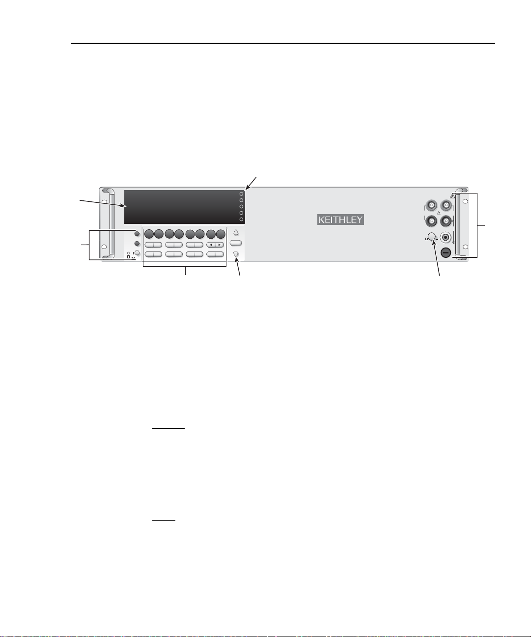
Fr ont and rear panel familiarization
Front panel summar y
The front panel of Model 2750 is shown in Figure 1-1.
Figure 1-1
Model 2750 front panel
NOTE Most keys provide a dual function or operation. The nomenclature on a key indi-
cates its unshifted function/operation, which is selected by pressing the key.
Nomenclature (in blue) above a key indicates its shifted function. A shifted function is selected by pressing the SHIFT key and then the function/operation key.
1 Special keys and power switch:
SHIFT Use to select a shifted function or operation.
LOCAL Cancels GPIB remote mode.
POWER Power switch. In position turns 2750 on (I), out position turns it off (O).
2 Function and operation keys:
Top Row
Unshifted
DCV Selects DC voltage measurement function.
ACV Selects AC voltage measurement function.
DCI Selects DC current measurement function.
ACI Selects AC current measurement function.
Ω2 Selects 2-wire resistance measurement function.
Ω4 Selects 4-wire resistance measurement function.
FREQ Selects frequency measurement function.
TEMP Selects temperature measurement function.
Shifted
MATH Configures and controls mX+b, percent, or reciprocal (1/X) calculation.
OUTPUT Configures and controls digital and audio (beeper) output for limits.
RATIO Enables/disables channel ratio.
CH-AVG Enables/disables channel average.
CONT Configures and controls continuity test.
OCOMP Enables/disables offset compensated ohms with Ω4 function selected.
PERIOD Selects period measurement function.
SENSOR Configures temperature measurements.
Page 27

1-10 Getting Started Model 2750 Multimeter/Switch System User’s Manual
Middle Row
Unshifted
EXTRIG Selects external triggering (front panel, bus, trigger link) as the trigger source.
TRIG Triggers a measurement when in external triggering (EX TRIG).
STORE Sets the number of readings to store and enables the buffer.
RECALL Displays stored readings and buffer statistics. Use the
igate through buffer.
FILTER Enables/disables filter for selected function.
REL Enables/disables relative for selected function.
, , Δ , and ∇ keys to nav-
and Dual function — Manually scans switching channels. When in a menu, these keys
control cursor position for making selections or change values.
Shifted
DELAY Sets user delay between trigger and measurement.
DRYCKT Selects dry circuit ohms (Ω4 must first be selected).
LIMITS Sets upper and lower limits for readings.
ON/OFF Enables/disables limits.
TYPE Configures and enables filter for selected function.
MONITOR Selects and enable/disables monitor channel.
CH-OFF Disables channel for a scan (must be in scan channel setup mode).
CARD Identifies switching modules installed in mainframe. Set up switching modules that
Bottom Row
Unshifted
OPEN Opens closed channel.
CLOSE Closes specified channel.
STEP Steps through channels; sends a trigger after each channel.
SCAN Scans through channels; sends a trigger after last channel.
DIGITS Sets display resolution for all functions.
RATE Sets measurement speed (fast, medium, or slow) for all functions.
EXIT Cancels selection, moves back to measurement display.
ENTER Accepts selection, moves to next choice or back to measurement display.
Shifted
SAVE Saves up to three instrument setups for future recall, and selects power-on setup.
SETUP Restores a default setup (factory or *RST) or a saved setup. Enables/disables buffer
CONFIG Selects and configures a simple scan or an advanced scan.
HALT Disables step/scan.
TEST Selects the calibration menu, display test or the key-press test.
LSYNC Enables/disables line cycle synchronization. When enabled, noise induced by the
GPIB Enables/disables GPIB and selects address.
RS-232 Enables/disables RS-232 interface; selects baud rate, flow control, and terminator.
require configuration. View closed channels and channel settings for switching mod-
ules that require configuration.
auto clear, auto scan, and auto channel configuration. Sets timestamp, date, and
time. Displays serial number of Model 2750.
power line is reduced at the expense of speed.
3 Range keys:
Δ and ∇ Dual function — Selects the next higher/lower measurement range for the selected
function. When in a menu, these keys make selections or change values.
AUTO Enables/disables autorange for the selected function.
Page 28

Model 2750 Multimeter/Switch System User’s Manual Getting Started 1-11
4 Display annunciators:
* (asterisk) Readings being stored in buffer.
↔ (more) Indicates additional selections are available.
))) (speaker) Beeper on for continuity or limits testing.
4W 4-wire resistance or 4-wire RTD temperature reading displayed.
DCKT Dry circuit resistance reading displayed.
~AC AC function selected (ACV, dB, or ACI).
AUTO Auto range enabled.
BUFFER Recalling readings stored in buffer.
CHAN Setup or a reading for a switching channel displayed.
DELTA Channel average enabled.
ERR Questionable reading, or invalid cal step.
FAST Fast reading rate selected.
FILT Filter enabled for selected function.
HIGH Reading has reached or exceeded the enabled high limit.
LSTN Instrument addressed to listen over GPIB.
LOW Reading has reached or exceeded the enabled low limit.
MATH mX+b, percent, or reciprocal (1/X) calculation enabled.
MED Medium reading rate selected.
MON Monitor channel displayed.
OCOMP 4-wire offset compensated ohms enabled.
RATIO Channel ratio enabled.
REAR Front panel input terminals disconnected.
REL Relative enabled for selected function.
REM Instrument in GPIB remote mode.
SCAN Scanning operation being performed.
SHIFT Accessing a shifted key.
SLOW Slow reading rate selected.
SRQ Service request over GPIB.
STAT Displaying buffer statistics.
STEP Stepping operation being performed.
TALK Instrument addressed to talk over GPIB bus.
TIMER Timer controlled triggering in use.
TRIG External triggering selected (trigger link, TRIG key, or GPIB).
Digital input/output or analog output active (set to non-default value).
5 Slot indicators:
Lit lamp indicates that the slot has a switching module or pseudocard installed in it. When the VIEW
option of the CARD menu is used, only the lamp that corresponds to the selected slot is turned on.
6 INPUTS switch:
Use to select front panel inputs (out; F) position, or switching module inputs (in; R) position.
NOTE For remote programming, the following command queries the INPUTS switch
position:
SYSTem:FRSwitch? ' Query INPUTS switch; 0 = rear, 1 = front.
7 Front panel inputs:
INPUT HI and LO Used for DCV, ACV, Ω2, CONT, FREQ, PERIOD, and thermocouple/thermistor
TEMP measurements.
SENSE HI and LO Use with INPUT HI and LO for
AMPS Use with INPUT LO for DCI and ACI measurements.
Amps fuse holder Holds current fuse for front panel amps input.
Ω4 and RTD TEMP measurements.
Page 29
1-12 Getting Started Model 2750 Multimeter/Switch System User’s Manual
IEEE-488
MADE IN
U.S.A.
!
CAT I
DIGITAL I/O TRIG. LINK
!
SLT
2
SLT
1
SLT
3
SLT
4
SLT
5
RS-232
KEITHLEY
SLOT COVER
KEITHLEY
SLOT COVER
KEITHLEY
SLOT COVER
5
4321
6
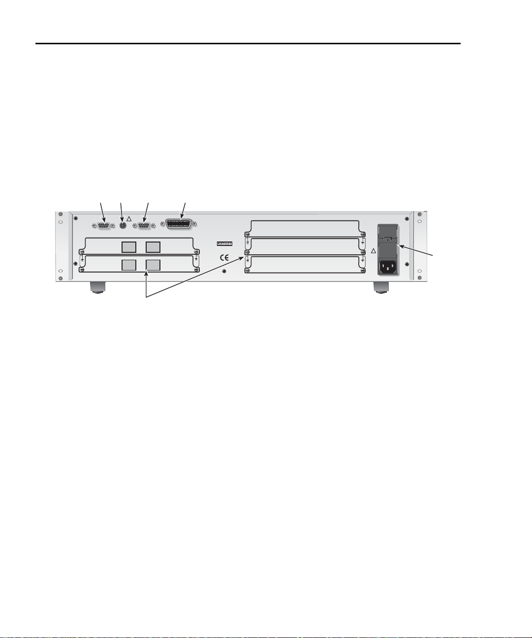
Rear panel summary
The rear panel of Model 2750 is shown in Figure 1-2. As shown, slot covers are installed
on unused slots.
WARNING Slot covers must be installed on unused slots to prevent personal con-
tact with high voltage circuits.
Figure 1-2
Model 2750 rear panel
1 DIGITAL I/O
Male DB-9 connector for digital input (trigger link in) and digital outputs.
2 TRIG LINK
Eight-pin micro-DIN connector for sending and receiving trigger pulses among connected instruments.
Use a trigger link cable or adapter, such as Models 8501-1, 8501-2, 8502, and 8503.
3 RS-232
Female DB-9 connector for RS-232 operation. Use a straight-through (not null modem) DB-9 shielded
cable.
4 IEEE-488
Connector for IEEE-488 (GPIB) operation. Use a shielded cable, such as Models 7007-1 and 7007-2.
5 Power module
Contains the AC line receptacle, power line fuse, and line voltage setting. The instrument can be configured for line voltages of 100V/120V/220V/240VAC at line frequencies of 50 or 60Hz.
WARNING Slot covers must be installed on unused slots to prevent personal con-
6 Slots 1 through 5
Five slots to accommodate Keithley Model 77XX series s witching modules. T he Model 2750 is shipped
from the factory with slot covers installed. Please note additional slot covers can be requested from Keithley Instruments.
tact with high voltage circuits.
Page 30
Model 2750 Multimeter/Switch System User’s Manual Getting Started 1-13
1.75”
Left Front
Rack Rail
Retaining Clips
with Nuts
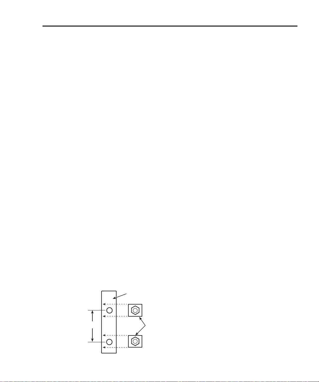
Rack mounting
The Model 2750 can be mounted in a standard 19-inch rack. For a mainframe that has one
or no switching modules installed, the Model 2750 can be secured to the front rails of the
rack.
The hardware necessary to secure the mainframe to the front rails of the rack is supplied
with the Model 2750. The supplied hardware kit includes four dress screws and four
retaining clips. Each retaining clip has a captive nut.
Perform the following steps to mount the Model 2750 to front rails of the rack:
WARNING Make sure the Model 2750 is turned off, the line cord is disconnected,
and it is not connected to any external circuitry.
1. Select a location in the rack. The mainframe takes up 3H-inches of vertical space.
2. Using Figure 1-3 as a guide, install two retaining clips on the left front rail. Slide
each retaining clip over a mounting hole such that the captive nut is positioned on
the inside of the rack cabinet. In a simila r manner, install two retaining clips on the
right front rail.
3. Remove the four foot assemblies from the bottom of the Model 2750. The retaining
screw for an assembly is located under the rubber foot. Simply pull off the rubber
feet to gain access to the screws. Retain these foot assemblies for future use.
4. Position the Model 2750 in the rack and loosely attach the front panel to the rack
rails using the four supplied dress screws.
5. Tighten the four dress screws.
CAUTION For a Model 2750 that has two or more installed switching modules,
rear brackets are required to support the additional weight. The Model
4288-7 is a rack mount kit for the Model 2750 that uses rear support
brackets.
Figure 1-3
Rack preparation
Page 31

1-14 Getting Started Model 2750 Multimeter/Switch System User’s Manual
Model 2750
IEEE-488
MADE IN
U.S.A.
!
CAT I
DIGITAL I/O TRIG. LINK
!
SLT
2
SLT
1
SLT
3
SLT
4
SLT
5
RS-232
KEITHLEY
SLOT COVER
KEITHLEY
SLOT COVER
KEITHLEY
SLOT COVER
Fuse
Spring
Window
Line Voltage
Selector
Fuse Holder Assembly
120
240
220
100
Power-up
Line power connection
Follow the procedure below to connect the Model 2750 to line power and turn on the
instrument.
1. Check to see that the line voltage indicated in the window of the fuse holder assembly (Figure 1-4) is correct for the operating voltage in your area. If not, refer to the
next procedure, “Setting line voltage and replacing fuse,” page 1-15.
CAUTION Operating the instrument on an incorrect line voltage may cause dam-
age to the instrument, possibly voiding the warranty.
2. Before plugging in the power cord, make sure that the front panel power switch is
in the off (O) position.
3. Connect the female end of the supplied power cord to the A C receptacle on the rear
panel. Connect the other end of the power cord to a grounded AC outlet.
WARNING The power cord supplied with the Model 2750 contains a separate
ground wire for use with grounded outlets. When proper connections
are made, instrument chassis is connected to power line ground
through the ground wire in the power cord. Failure to use a grounded
outlet may result in personal injury or death due to electric shock.
4. Turn on the instrument by pressing the front panel power switch to the on (I)
position.
Figure 1-4
Power module
Page 32

Model 2750 Multimeter/Switch System User’s Manual Getting Started 1-15
Line frequenc y
The Model 2750 will operate at line frequencies from 45Hz to 66Hz, and 360Hz to 440Hz.
There are no user-settings for line frequency. It is automatically sensed at power-up. The
following command can be used to read the line frequency:
SYSTem:LFRequency? ' Query power line frequency.
Setting line voltage and replacing fuse
A rear panel fuse located next to the AC receptacle protects the power line input of the
instrument. If the line voltage setting needs to be changed or the line fuse needs to be
replaced, perform the following steps.
WARNING Make sure the instrument is disconnected from the AC line and other
equipment before changing the line voltage setting or replacing the line
fuse.
1. Place the tip of a flat-blade screwdriver into the power module by the fuse holder
assembly (Figure 1-4). Gently push in and up. Release pressure on the assembly
and its internal spring will push it out of the power module.
2. Remove the fuse and replace it with the type listed in Table 1-2.
CAUTION For continued protection against fire or instrument damage, only
replace fuse with the type and rating listed. If the instrument repeatedly blows fuses, locate and correct the cause of the trouble before
replacing the fuse.
3. If configuring the instrument for a different line voltage, remove the line voltage
selector from the assembly and rotate it to the proper position. When the selector is
installed into the fuse holder assembly, the correct line voltage appears sidew ays in
the window.
4. Install the fuse holder assembly into the power module by pushing it in until it
locks in place.
Table 1-2
Fuse ratings
Line voltage Fuse rating Keithley P/N
100/120V
220/240V
0.630A, 250V, slow-blow 5× 20mm
0.315A, 250V, slow-blow 5× 20mm
FU-106-.630
FU-106-.315
Page 33

1-16 Getting Started Model 2750 Multimeter/Switch System User’s Manual
Po wer -up sequence
On power-up, the Model 2750 performs self-tests on its EPROM and RAM and momentarily lights all segments and annunciators. If a failure is detected, the instrument momentarily displays an error message and the ERR annunciator turns on. (Error messages are
listed in Appendix C).
NOTE If a problem develops while the instrument is under warranty, return it to
Keithley Instruments, Inc., for repair.
If the instrument passes the self-tests, the firmware revision levels are displayed. An
example of this display is:
REV: A01 A01
where: First A01 is the main board ROM revision.
Second A01 is the display board ROM revision.
Installed switching modules are then displayed. For example, if there is a Model 7700
switching module installed in all five slots, the following messages will be displayed:
1: 7700 2: 7700
3: 7700 4: 7700
5: 7700
If a slot is empty, the message “NONE” will be displayed instead.
If the saved power-on setup is not the factory defaults setup (SYSTem:POSetup PRESet),
a message to identify the setup will be briefly displayed (“Defaults and user setups,”
page 1-19).
After the power-up sequence, the instrument begins its normal display of readings.
NOTE The serial number of the Model 2750 can be displayed by selecting the SNUM
Keyclick
With keyclick enabled, an audible “click” will sound when a front panel key is pressed.
Perform the following steps to disable or enable keyclick:
item of the SETUP menu. Press SHIFT and then SETUP to access the menu. F or
remote operation, the serial number can be read using the *IDN? command (see
Section 12 for details).
1. Press SHIFT and then LOCAL to display the present state of KEYCLICK (ON or
OFF).
2. Press
Δ or ∇ to display the desired keycl i c k stat e and pr ess EN TER.
Page 34

Model 2750 Multimeter/Switch System User’s Manual Getting Started 1-17
Remote programming
The following command controls keyclick:
SYSTem:KCLick <b> ' Enable or disable keyclick.
where: <b> = ON or OFF
NOTE Keyclick ON is the FACTORY, *RST, and SYSTem:PRESet default.
Display
Readings are displayed in engineering units (i.e., 100.23mV), while annunciators indicate
various states of operation. See “Front panel summary ,” page 1-9, for a complete listing of
display annunciators.
NOTE The display test allows you to test display digit segments, annunciators and the
red slot indicator LEDs. The key test chec ks the functionality of fr ont panel ke ys.
These tests are accessed by pressing SHIFT and then TEST. Refer to the Model
2750 Service Manual for details.
Status and error messages
Status and error messages are displayed momentarily. During operation and programming,
you will encounter a number of front panel messages. T ypical messages are either of status
or error variety, as listed in Appendix C.
Remote programming — displa y
Using remote programming, the Model 2750 can display a custom ASCII message (up to
12 characters). Also, the front panel display and controls can be disabled.
Display commands
The commands are listed in Table 1-3. Details on these commands follow the table.
NOTE Optional command words and queries are not included in Table 1-3. Table 15-2
provides an unabridged list of all display commands.
Table 1-3
Display commands
Command Description Default*
DISPlay:TEXT:DATA <a> Define message (<a> = ASCII characters,
up to 12).
DISPlay:TEXT:STATe <b> Enable or disable message mode (<b> = ON
or OFF).
DISPlay:ENABle <b> Enable or disable the front panel display
(<b> = ON or OFF).
*SYSTem:PRESet and *RST have no effect on DISPlay commands. The listed defaults are power-on defa ults.
(none)
OFF
OFF
Page 35

1-18 Getting Started Model 2750 Multimeter/Switch System User’s Manual
DISPlay:TEXT:DA T A <a> Define text message
This command defines the text message for display. A message can be as long as 12 characters. A space counts as a character. Excess message characters results in an error. The
characters must be enclosed in either single quotes (‘ ’) or double quotes (“ ”).
DISPlay:TEXT:STA Te ON | OFF Control (on/off) message for display
This command enables and disables the text message mode. When enabled, a defined message is displayed. When disabled, the message is removed from the display.
A user defined text message remains displayed only as long as the instrument is in remote.
Taking the instrument out of remote (by pressing the LOCAL key or sending GTL) cancels the message and disables the text message mode.
DISPlay:ENABle ON | OFF Control display circuitry
This command is used to enable and disable the front panel display circuitry. When disabled, the instrument operates at a higher speed. While disabled, the display is blanked.
All front panel controls (except LOCAL) are disabled. Normal display operation can be
resumed by using the ENABle command to enab le the display or by putting the Mo d e l
2750 into local mode (press LOCAL).
Programming e xample
The following command sequence displays the text message “TESTING”:
DISP:TEXT:DATA 'TESTING' ' Define text message.
DISP:TEXT:STAT ON ' Enable text message mode.
Page 36

Model 2750 Multimeter/Switch System User’s Manual Getting Started 1-19
Defaults and user setups
Model 2750 can be restored to one of two default setup configurations (FACTory or
*RST), or three user-saved (SAV0, SAV1, or SAV2). As shipped from the factory,
Model 2750 powers up to the factory (FACT) default settings.
NOTE Closed channels can be saved in a user setup (SAV0, SAV1, or SAV2). When the
setup is restored, those c hannels (and only those channels) will be closed. FACT
and *RST defaults opens all channels.
The factory default setup provides continuous triggering, while the *RST default setup
places the Model 2750 in the one-shot trigger mode. With one-shot triggering, a measurement is performed whenever the TRIG key is pressed or an initiate command is sent over
the remote interface.
The factory and *RST default settings are listed in Table 1-4. Setting differences (Set Diff)
between the two default setups are indicated by checkmarks (✓).
For remote programming, the SYS Tem:PRESet and *RST commands are used to reset the
instrument. The *RST command returns the instrument to the *RST defaults and, for the
most part, the SYSTem:PRESet command returns the instrument to the factory default
conditions. The exceptions are explained as follows:
• Auto scan and auto channel configuration — FACTory defaults disable auto scan
and auto channel configuration, while SYSTem:PRESet has no effect. The *RST
defaults (front panel and remote operation) have no effect.
• Memory buffer auto clear — FACT ory def a ults enable buffer auto clear , while
SYSTem:PRESet has no effect. The *RST defaults (front panel and remote operation) have no effect.
The instrument will power up to whichever default setup is saved as the power-on setup.
NOTE At the factory, the factory default setup is saved as the SAV0, SAV1, or SAV2
setups.
Page 37

1-20 Getting Started Model 2750 Multimeter/Switch System User’s Manual
Saving and restoring setups
Saving a user setup
1. Configure Model 2750 for the desired measurement application.
2. Press SHIFT and then SAVE to access the save setup menu.
3. Press to place the cursor on the present setup (SAV0, SAV1, or SAV2).
4. Use the
returns to the normal measurement state.
WARNING If you make firmware upgrades you will lose all your saved settings.
Saving a pow er -on setup
1. Configure Model 2750 for the desired measurement application.
2. Press SHIFT and then SAVE to access the save setup menu.
3. Press the
SAV0, SAV1, or SAV2.
4. Press to place the cursor on the present power-on setup.
5. Use the
returns to the normal measurement state.
Δ or ∇ key to display the desired setup and press ENTER. The instrument
Δ key to display the present power-on (PWR-ON) setup: FACT, *RST,
Δ or ∇ key to display the desired setup and press ENTER. The instrument
Restoring a setup
1. Press SHIFT and then SETUP to access the restore setup menu.
2. Press to place the cursor on the present RESTORE setup (FACT, *RST, SAV0,
SAV1, or SAV2).
3. Use the
returns to the normal measurement state.
NOTE If the settings for a user setup or power-on setup do not match the switching
Δ or ∇ key to display the desired setup and press ENTER. The instrument
module types presently installed in the Model 2750, error +520 (Saved setup
scancard mismatch) occurs when the setup is recalled. The scan lis t will reset to
the factory defaults and all channels will open. However, the saved setup is still
retained in memory and can be restor ed when the matching switching module is
later installed.
Page 38

Model 2750 Multimeter/Switch System User’s Manual Getting Started 1-21
Table 1-4
Default settings
Setting Factory *RST Set Diff
Auto channel configuration No (off) No effect ✓
Autozero On On
Buffer No effect No effect
Auto clear Yes (on) No effect ✓
Channel Average Off Off
Closed channels None None
Closure count interval No effect No effect
Continuity
Beeper On On
Digits 4H digits 4H digits
Range 1kΩ 1kΩ
Rate Fast (0.1 PLC) Fast (0.1 PLC)
Threshold level 10Ω 10Ω
Current (AC and DC)
Bandwidth (AC) 30 30
Digits (AC) 5H digits 5H digits
Digits (DC) 6H digits 6H digits
Filter On Off ✓
Window 0.1% 0.1%
Count 10 10
Type Moving Repeat ✓
Range Auto Auto
Rate (DC) Slow (5 PLC) Slow (5 PLC)
Rel Off Off
Dry circuit ohms Off Off
Frequency and Period
Digits 6H digits 6H digits
Range 10V 10V
Rate (aperture) 1 second 1 second
Rel Off Off
Function DCV
GPIB No effect No effect
Address No effect (16 at factory) No effect (16 at factory)
Keyclick On On
Page 39

1-22 Getting Started Model 2750 Multimeter/Switch System User’s Manual
Table 1-4 (continued)
Default settings
Setting Factory *RST Set Diff
Limits Off Off
LO Limit 1 -1 -1
HI Limit 1 +1 +1
LO Limit 2 -2 -2
HI Limit 2 +2 +2
Line Synchronization Off Off
Math
mX+B Off Off
Scale Factor 1.0 1.0
Offset 0.0 0.0
Units “X” “X”
Percent Off Off
Reference 1.0 1.0
1/X (Reciprocal) Off Off
Monitor Off Off
Output
Beeper Never Never
Digital Output Off Off
Logic Sense High High
Pulse No (off) No (off)
Ratio Off Off
Resistance (Ω2 and Ω4)
Digits 6H digits 6H digits
Filter On Off ✓
Window 0.1% 0.1%
Count 10 10
Type Moving Repeat ✓
Offset compensation (OCOMP) Off Off
Dry circuit Off Off
Range Auto Auto
Rate Slow (5 PLC) Slow (5 PLC)
Rel Off Off
Page 40

Model 2750 Multimeter/Switch System User’s Manual Getting Started 1-23
Table 1-4 (continued)
Default settings
Setting Factory *RST Set Diff
RS-232 Off Off
Baud rate No effect No effect
Flow control XonXoFF XonXoFF
Terminator No effect No effect
Scanning Disabled Disabled
Auto scan No (off) No effect ✓
Type (Simple or Advanced) No effect No effect
Simple scan
Minimum channel 101, 201, 301, 401, or 501 101, 201, 301, 401, or 501
Maximum channel No effect No effect
Timer Off Off
Reading count No effect No effect
Advanced scan
Setup No effect No effect
Immediate trigger On On
Limit triggers Off Off
Timer Off Off
Reading count No effect No effect
Temperature
Digits 5H digits 5H digits
Filter On Off ✓
Window 0.1% 0.1%
Count 10 10
Type Moving Repeat ✓
Rate Slow (5 PLC) Slow (5 PLC)
Rel Off Off
Sensor Thermocouple Thermocouple
Junction See Note See Note
Open detector No (off) No (off)
Type K K
Units °C °C
Timestamp No effect No effect
Triggering Continuous One-shot ✓
Delay Auto Auto
Source Immediate Immediate
Page 41

1-24 Getting Started Model 2750 Multimeter/Switch System User’s Manual
Table 1-4 (continued)
Default settings
Setting Factory *RST Set Diff
Voltage (AC and DC)
dB Off Off
Reference 1.0 1.0
Digits (AC) 5H digits 5H digits
Digits (DC) 6H digits 6H digits
Filter On Off ✓
Window 0.1% 0.1%
Count 10 10
Type Moving Repeat ✓
Range Auto Auto
Rate (DC) Slow (5 PLC) Slow (5 PLC)
Rel Off Off
Note: With a Model 7700, 7706, or 7708 installed, the default sensor junction is Internal. Otherwise, the Simulated (23ºC) junction is
selected.
Remote progr amming — default and user setups
Default and user setup commands are listed in Table 1-5.
NOTE The SYSTem:PRESet and *RST defaul ts are listed in the SCPI tables in
Section 15.
Table 1-5
Default setup commands
Commands Description
SYSTem:PRESet Restore SYSTem:PRESet defaults.
*RST Restore *RST defaults.
*SAV <NRf> Save settings as user-setup; <NRf> = 0, 1 or 2.
*RCL <NRf> Restore user-saved setup; <NRf> = 0, 1 or 2.
SYSTem:POSetup <name> Specify power-on setup; <name> = RST , PRESet, SAV0,
SAV1, or SAV2.
Page 42

Model 2750 Multimeter/Switch System User’s Manual Getting Started 1-25
Programming e xample
*SAV 2 ' Save present setup in memory location 2.
SYST:POS SAV2 ' Specify SAV2 setup as the power-on setup.
*RST ' Return 2750 to RST defaults.
*RCL 2 ' Return 2750 to setup stored in memory location 2.
Remote progr amming information
Remote programming information is integrated with front panel operation throughout this
manual. Programming commands are listed in tables, and additional information that pertains exclusively to remote operation is provided after each table. The tables may reference you to other sections of this manual.
NOTE Except for Section 11 through Section 15, most programming tables in th is man-
ual are abridged. That is, they e xclude most optional command words and query
commands. Optional command words and query commands are summarized as
follows.
Optional command words — In order to be in conformance with the IEEE-488.2 standard, Model 2750 accepts optional command words. Any command word that is enclosed
in brackets ([]) is optional and does not have to be included in the program message.
Query commands — Most command words have a query form. A query command is
identified by the question mark (?) that follows the command word. A query command
requests (queries) the programmed status of that command. When a query command is
sent and Model 2750 is addressed to talk, the response message is sent to the computer.
NOTE For complete details, see “Programming syntax,” page 1 0-11 .
Quick start ex ercises
This section topic summarizes the following basic instrument operations and provides
simple exercises to perform them:
• Basic DMM measurements — front panel inputs
• Closing and opening channels — system channel operation
• Simple scanning
• Trigger and return readings — remote programming
WARNING For the exercises, it is not necessary to connect an input signal or DUT
to the instrument (front panel inputs or switching module inputs).
However, if you decide to use an input signal, it is recommended that
you keep it at a nonhazardous level (<42V) while learning to use the
instrument.
Page 43

1-26 Getting Started Model 2750 Multimeter/Switch System User’s Manual
NOTE When using the front panel input terminals, the INPUT switch must be in the
“F” (out) position. The INPUT switch is located on the right side of the front
panel near the input terminals. When using a switching module, the switch must
be in the “R” (in) position.
Basic DMM measurements — front panel inputs
NOTE See Section 3 for details on basic DMM operation.
The Model 2750 is shipped from the factory to power-up to factory defaults. The instrument powers up to a setup that continuously measures DC volts. Some of the default settings for the DCV function include auto range enabled, 6½-digit resolution, filter enabled,
and slow reading rate. These settings provide a good starting point and in many cases, do
not need to be changed.
“Starting-point” default settings are also provided for the other measurement functions.
Therefore, to perform basic measurements, simply select the desired function, and
“tweak” the setup (range, rate, filter, digits, etc.) as required.
For remote programming, the instrument is typically used in a non-continuous measurement mode. In this mode, the user (via remote command programming) specifies the number of measurements to perform. *RST defaults place the instrument in a non-continuous
measurement mode. Most of the other settings for factory and *RST defaults are the same.
For remote programming, the following command is used to select function.
NOTE Items in brackets ([]) are optional and do not need to be included. Upper case
characters are required. Lower case characters are optional and need not be
included.
[SENSe[1]]:FUNCtion <func> ' Select measurement function.
<func> = 'VOLTage[:DC]' DCV
'VOLTage:AC' ACV
'CURRent[:DC]' DCI
'CURRent:AC' ACI
'RESistance' Ω2
'FRESistance' Ω4
'FREQuency' FREQ
'PERiod' PERIOD
'TEMPerature' TEMP
Each function can have its own unique setup configuration (i.e., range, digits, speed, etc.).
For example, the following command words select range and digits:
RANGe[:UPPer] <n> ' Specify expected reading.
RANGe:AUTO <b> ' Enable (ON) or disable (OFF) auto range.
DIGits ' Set display resolution; 3.5, 4.5, 5.5 or 6.5 (digits).
Page 44

Model 2750 Multimeter/Switch System User’s Manual Getting Started 1-27
The following examples demonstrate how to include the function name in the command
string for configuration commands.
VOLT:RANG 10 ' Select 10V range for DCV.
RES:RANG:AUTO ON ' Enable auto range for W2.
CURR:DIG 4.5 ' Set DCI for 4½- digit resolution.
NOTE See Section 4 for details on setting range, digits, rate, bandwidth, and filter.
Exercise 1 — Basic DMM measur ements
The exercise in Table 1-6 measures ACV on the 10V range and stores 15 readings in the
buffer.
Table 1-6
Exercise 1 — Measure AC volts - store readings in buffer
Front panel operation Command sequence
1 For front panel operation, proceed to step 2.
For remote programming, clear the buffer
1
:
TRAC:CLE
2 Restore defaults2:
Press SHIFT > press SETUP > select RESTORE: FACT.
*RST
3 Select ACV function:
Press ACV.
FUNC 'VOLT:AC'
4 Select 10V range:
Press RANGE
Δ to display “RANGE: 10V”.
VOLT:AC:RANG 10
6 Store 15 readings in buffer3:
Press STORE > set for 000015 RDGS > press ENTER.
SAMP:COUN 15
READ?
7 Recall buffer readings4:
Press RECALL > use edit keys to display readings. Press EXIT to exit
CALC1:DATA?
recall mode.
1. To a v o id problems with remote programming, it is good practice to routinely clear th e buffer (TRAC:CLE) at the beginning
of a program that performs multiple measurements (
the buffer.
2. FACTory defaults place the instrument in a continuous measurement mode. *RST places the instrument in a noncontinuous measurement mode.
3. READ? triggers and returns 15 readings. These 15 readings are automatically stored in the buffer. See Exercise 4 and 5 for
more information on the READ? command.
4. Statistics for buffer readings are also stored in the buffer. For remote programming,
ings that were stored. It does not return buffer statistics.
(see Section 6 for details).
SAMP:COUN >1). Restoring *RST or F ACTory defaults does not clear
CALC1:DATA? only returns the read-
CALC2 commands are used to calculate and return buffer statistics
Page 45

1-28 Getting Started Model 2750 Multimeter/Switch System User’s Manual
DMM
DUT
DMM
Switching Module Switching Module
HI
LO
HI
LO
Input
Ch 1
HI
LO
HI
LO
Input
Ch 1
Closing and opening channels — system channel oper ation
NOTE See Section 2 for details on closing and opening switching module channels.
NOTE The following discussion assumes a multiplexing switching module (i.e., Model
7700) installed in slot 1 of the mainframe. Switching module installation is covered in “Switching module installation and connections,” page 2-3.
An alternative to installing a switching module is to assign slot 1 as a
pseudocard using remote programming. The instrument will operate as if a
switching module is installed in slot 1. To “install” a 7700 pseudocar d in slot 1,
send the following command:
SYST:PCAR1 C7700
System channel operation is used to connect input channels to the DMM of the Model
2750:
• For a 2-wire function (i.e., DCV), closing a system channel connects the input to
DMM Input of the Model 2750.
Figure 1-5 shows system channel 1 closed. For the Ω2 function, the resistance
(DUT) would be connected to DMM Input as shown Figure 1-5.
• For a 4-wire function (i.e., Ω4), a channel pair is connected to the DMM when a
system channel is closed. The system channel is connected to DMM Input and the
paired channel is connected to DMM Sense.
Figure 1-6 shows system channel 6 closed. For a 4-wire function, the paired chan-
nel also closes. For the Model 7700, channels 1 through 10 are paired to channels
11 through 20. When channel 6 is closed, channel 16 also closes. Figure 1-6 shows
how the DUT is connected to the DMM for the 4-wire function.
NOTE Figure 1-5 and Figure 1-6 show simplified schematics of the switching module.
They show a single switch closed to connect an input channel to the DMM. In
reality, multiple switching to is used to make proper connections to the DMM.
However, for system channel operation, the user need not be concerned about
which switches in the module close.
Figure 1-5
Connection to DMM for 2-wire function (system channel 101 closed)
Page 46

Model 2750 Multimeter/Switch System User’s Manual Getting Started 1-29
DUT
DMM DMM
7700
Switching Module
7700
Switching Module
HI
LO
HI
LO
Input
Ch 6
HI
LO
HI
LO
Sense
Ch 16
HI
LO
Input
HI
LO
HI
LO
Sense
Ch 16
HI
LO
Ch 6
Figure 1-6
Connectio n to DMM for 4-wire function (system channel 106 closed)
NOTE Switching module channels can also be contr olled using multiple channel opera-
tion. This allows individual control of all module channels (switches). Multiple
channel operation should only be used by experienced service personnel who
recognize the dangers associated with multiple channel closures. See Section 2
for details.
Close/open operation
The following points on operation pertain to system channel operation only:
• Only one input channel (or channel pair) is closed at one time. When you close an
input channel, the previously closed input channel(s) will open.
• When a system channel is closed, the channel number will be displayed on the
Model 2750. The slot number for the module is also displayed. For example, “103”
indicates that system input channel 3 for a module in slot 1 is closed.
• The paired channel for a 4-wire function is not displayed. Only the system channel
number is displayed. For example, in Figure 1-6, channel number 106 will be displayed with the Model 7707 installed in slot 1 of the mainframe.
• Switching modules that have current measurement capability have separate channels reserved exclusively for the DCI and ACI functions. For example, the Model
7700 has channels 21 and 22 reserved for amps measurements. With the DCI or
ACI function selected, only channels 21 and 22 can be closed. These channels cannot be accessed on any other function.
Figure 1-7 shows the front panel keys used to close and open system channels.
Page 47

1-30 Getting Started Model 2750 Multimeter/Switch System User’s Manual
Close next
measurement
channel
Close previous
measurement
channel
CLOSEOPEN
CLOSE CH: XXX
CLOSE:SINGLE
Press CLOSE key
Display SINGLE option
and press ENTER
Specify channel
number (XXX) and
press ENTER
CLOSEOPEN
OPEN: ALL
Press OPEN key
Display ALL
option and press
OPEN again
A. Sequencing through channnels B. Specifiying channel to close C. Opening all channels
Figure 1-7
Front panel keys to close and open system channels
For remote programming, the following three commands are used for basic system operation to open and close input channels:
ROUTe:CLOSe <clist> ' Close specified system channel1.
ROUTe:CLOSe? ' Query closed system channel
ROUT:OPEN:ALL ' Open all channels.
2
.
1. Only one channel can be specified in the <clist>. For example, to close input channel 3 for a module in slot 1, the following command would be sent:
ROUTe:CLOSe (@103)
2. Only the closed system channel is returned by ROUTe:CLOSe?. The paired channel
for a 4-wire function is not returned. For example, assume channel 2 in slot 1 is
closed. The following response message will be returned:
(@102)
Page 48

Model 2750 Multimeter/Switch System User’s Manual Getting Started 1-31
Exercise 2 — Closing and opening c hannels (system channel oper ation)
The exercise in Table 1-7 demonstrates a sequence to close and open channels of a Model
7700 installed in slot 1 of the mainframe.
Table 1-7
Exercise 2 — Close and open channels (system channel operation)
Front panel operation Command sequence
1 Open all channels*:
Press OPEN > display OPEN:ALL > Press OPEN.
ROUT:OPEN:ALL
2 Select Ω2 function:
Press Ω2.
FUNC 'RES'
3 Close system channel 101:
Press the key. Channel 1 connects to DMM Input (see Figure 1-5).
ROUT:CLOS (@101)
4 Close system channel 102:
Press the key. Channel 2 connects to DMM Input.
ROUT:CLOS (@102)
5 Close system channel 106:
Press CLOSE > select CLOSE:SINGLE > key in channel 106 > press
ROUT:CLOS (@106)
ENTER. Channel 6 connects to DMM Input.
6 Select Ω4 function:
Press Ω4. 4W annunciator turns on, and channels 6 and 16 connects to
FUNC 'FRES'
DMM Input and Sense (see Figure 1-6).
7 Open all channels*:
Press OPEN > display OPEN:ALL > Press OPEN ROUT:OPEN:ALL
*It is a good, safe practice to start and end a switching sequence by opening all channels.
Simple scanning
NOTE See Section 7 for details on scanning.
With at least one multiplexer switching module (i.e., Model 7700) installed in the mainframe, the instrument can scan channels that are valid for the selected function.
For front panel operation, Figure 1-8 shows the three basic steps to configure and run a
simple scan. The differences between the STEP function and the SCAN function involve
the reading count and the timer.
Reading count (RDG CT) — For both STEP and SCAN, the reading count specifies the
number of readings to store in the buffer . For STEP, the reading count determines the number of channels to scan.
For SCAN, the reading count also determines the number of scans to perform and is best
explained by an example. Assume there are 10 channels in the scan list (i.e., 101 through
110). If you set the reading count to 10 or less, one scan of the 10 channels will be performed. If you set the reading count to any value from 11 to 20, two scans will be performed. A reading count from 21 to 30 gives you three scans, and so on.
Page 49

1-32 Getting Started Model 2750 Multimeter/Switch System User’s Manual
MIN CHAN: XXX
INT: SIMPLE
Display SIMPLE option
and press ENTER
Specify minimum channel
(XXX) and press ENTER
SHIFT
SCANSTEP
CONFIG
Press SHIFT
Press CONFIG (STEP)
MAX CHAN: YYY
Specify maximum channel
(YYY) and press ENTER
TIMER? NO/YES
Display NO or YES and
press ENTER
YESNO
xxH:xxM:xx.xxxS
Set timer interval in
hr:min:sec format and
press ENTER
RDG CT:xxxxxx
Specify reading count and press
ENTER
SCANSTEP
Press STEP or SCAN to start
scan
Timer interval specifies time
between scans.
Reading count:
Specifies number of scans
to be performed.
Specifies number of readings
to store in buffer.
Timer interval specifies time between
scanned channels.
Reading count:
Specifies number of channels to be
scanned.
Specifies number of readings to store
in buffer.
Step 1. Configure simple scan: Step 2. Run simple scan:
SHIFT
SCANSTEP
HALT
Press SHIFT
Press HALT (SCAN)
Step 3. Disable scan mode:
Timer interval (TIMER) — For the STEP function, the timer specifies the time delay
between scanned channels. For the SCAN function, the interval specifies the time delay
between scans. The timer starts when the scan is started. For SCAN, the next scan will not
start until the timer interval expires.
NOTE The Model 2750 can also be configured to run an advanced scan. For an
advanced scan, each channel can have its own unique setup (i.e., function,
range, etc.). Advanced scanning is covered in Section 7.
Figure 1-8
Simple scan operation
Page 50

Model 2750 Multimeter/Switch System User’s Manual Getting Started 1-33
For remote programming, the following commands are used for simple scanning:
ROUTe:SCAN <clist> ' Define scan list*.
TRIGger:COUNt <NRf> ' Specify number of scans (1 to 11000 or
' INFinity).
SAMPle:COUNt <NRf> ' Specify number of channels to scan
ROUTe:SCAN:LSELect <name> ' Enable (INT) or disable (NONE) scan.
' (1 to 11000).
*Any valid switching module channel can be included in the scan list. Make sure to list
them from the lowest numbered channel to the highest. For example, to scan channels 1
through 8 of a Model 7700 installed in slot 1, send the following command to define the
scan list:
ROUTe:SCAN (@101:108)
Exercise 3 — Simple scanning
The scanning example in Table 1-8 assumes a Model 7700 installed in slot 1 of the mainframe. The scan will use default settings (DCV) to scan eight channels and store the readings in the buffer.
Table 1-8
Exercise 3 — Simple scanning
Front panel operation Command sequence
1 For front panel operation, proceed to step 2.
For remote programming, clear the buffer:
TRAC:CLE
2 Restore defaults1:
Press SHIFT > press SETUP > select RESTORE: FACT.
*RST
3 Configure scan:
Press SHIFT > press CONFIG > select INT: SIMPLE > set MIN
CHAN101 > set MAX CHAN: 108 > select TIMER? NO > set RDG
ROUT:SCAN (@101:108)
SAMP:COUN 8
CT:000008.
4 Enable and start scan2:
Press STEP.
ROUT:SCAN:LSEL INT
INIT
5 Halt (disable) scanner:
Press SHIFT > press HALT.
ROUT:SCAN:LSEL NONE
6 Recall the eight stored readings:
Press RECALL > use edit keys to display readings. Press EXIT to
CALC1:DATA?
exit recall mode.
7 Open all channels:
Press OPEN > display OPEN:ALL > Press OPEN
1. Factory and *RST defaults opens all channels, select the DCV function and sets TRIG:COUN to 1. The trigger count specifies the number of scans to be performed.
2. ROUT:SCAN:LSEL INT enables the scan, and INIT triggers the start of the scan.
ROUT:OPEN:ALL
Page 51

1-34 Getting Started Model 2750 Multimeter/Switch System User’s Manual
T rigger and return readings — r emote progr amming
There are several commands used to trigger and return readings. The proper commands
and sequence to use depend on trigger state (continuous or non-continuous) and what you
are trying to accomplish.
Presented here are three fundamental command sequences that can be used to “trigger and
return readings.” These three command sequences (exercises) will accommodate most
basic measurement scenarios. Simply use the command sequence (exercise) that satisfies
your needs:
• Exercise 4 — Trigger and return a single reading
• Exercise 5 — Trigger and return multiple readings
• Exercise 6 — Return a single reading (continuous triggering)
Details on the commands to trigger and return readings are provided in other sections of
this manual. For details, refer to the following sections:
Section 3 — See “Trigger and retrieve readings” in Table 3-8.
Section 7 — For scanning, see “Trigger commands” in Table 7-1.
Section 8 — Explains the triggering process.
Section 13 — Covers Signal Oriented Measurement Commands (i.e., FETCh?, READ?).
Section 15 — See Table 15-9 (Trigger command summary).
Appendix D — Shows how trigger and read commands control data flow within the
instrument.
NOTE Each exercise indicates the commands used to configure triggering. Once
triggering is configured, the commands to trigger and/or return readings can
be repeated as often as desired (unless noted otherwise).
Exercise 4 — Trigger and return a single reading
Exercise 5 — Trigger and return multiple readings
Trigger controlled measurements — The instrument is typically used in a non-continuous trigger mode. In this mode, commands are used to trigger one or more readings. After
the specified number of readings are completed, the measurement process stops.
Exercise 4 in Figure 1-9 provides a command sequence to trigger and return one reading.
Exercise 5 in Figure 1-10 provides a command sequence to trigger and return multiple
readings.
Exercise 6 — Return a single reading (continuous triggering)
Readings can be returned while the instrument is in the continuous measurement (trigger)
mode. Each time a read command is sent, the latest reading is returned. Exercise 6 in
Figure 1-11 provides a command sequence to return a single reading while in the continu-
ous trigger state.
Page 52

Model 2750 Multimeter/Switch System User’s Manual Getting Started 1-35
INIT:CONT OFF
TRIG:COUN 1
SAMP:COUN 1
Place 2750 in
non-continuous
trigger state
Set 2750 to perform
one measurement
1. If a MATH function (mX+B, percent or 1/X) is enabled, the result of the calculation will
be returned (MATH functions are covered in Section 5).
3. FETCh?, CALC:DATA?, and DATA? do not trigger readings. They simply return the last
reading. If you again send one of these commands before triggering a new reading, the
old reading will be returned.
Return Basic Reading
3,4
INITTrigger Reading
READ?
2. If there is no MATH function enabled,
FETCh?and CALC:DATA? will return the basic
reading.
Trigger and Return
Reading
1
Trigger Configuration
Trigger and Return
Reading
DATA?
OR
DATA:FRESh?
Return Result of MATH
Calculation
1, 2, 3
4. DATA:FRESh? can only be used once to return the same reading. Sending it again
without first triggering a new reading will cause error -230 (data corrupt or stale).
FETCh?
OR
CALC:DATA?
Figure 1-9
Exercise 4 — Trigger and return a single reading
Page 53

1-36 Getting Started Model 2750 Multimeter/Switch System User’s Manual
INIT:CONT OFF
TRIG:COUN 1
SAMP:COUN x
READ?
INIT
FETCh?
Place 2750 in non-continuous
trigger state
Set 2750 to perform “x”
number of measurements
(x = 2 to 110000)
2. INIT triggers the measurements, and FETCh? returns the readings. Again sending
FETCh? without first sending INIT will return old readings.
4. Triggered readings are automatically stored in the buffer. Statistics for buffer readings
are also stored in the buffer. CALC2 commands are used to calculate and return
buffer statistics (see Section 6 for details).
TRAC:CLE
Clear Buffer
1
Trigger and Return
Readings
2, 3
3. READ? performs an INIT to trigger the measurements, and then FETCh? to return
the reading(s).
OR
TRAC:DATA?
Return Stored Readings
4
Trigger and Return
Readings
Trigger Configuration
1. In order to trigger and return multiple readings, the buffer must first be cleared of
readings that were stored by the TRACe command or front panel operation (see
Section 6 for details on buffer operation).
Figure 1-10
Exercise 5 — Trigger and return multiple readings
Page 54

Model 2750 Multimeter/Switch System User’s Manual Getting Started 1-37
SAMP:COUN 1
INIT:CONT ON
DATA?
DATA:FRESh?
FETCh?
CALC:DATA?
Place 2750 in
continuous
trigger state.
OR
OR
Return Basic Reading
2, 3
Return result of MATH
Calculation
1, 2
1. If a MATH function (mX+B, percent or 1/X) is enabled, the result of the calculation will
be returned.
If there is no MATH function enabled, FETCh? and CALC:DATA? will return
the basic reading.
MATH functions are covered in Section 5.
2. None of these read commands trigger measurements. They simply return the lastest
reading. If FETCH?, CALC:DATA?, or DATA? is again sent before a new reading is
triggered, the ld reading will be returned.
3. DATA:FRESh? can only be used once to return the same reading. Sending it again before
a new reading is triggered will cause error -230 (data corrupt or stale).
Return Readings
Trigger Configuration
Figure 1-11
Exercise 6 — Return a single reading (continuous triggering)
Page 55

1-38 Getting Started Model 2750 Multimeter/Switch System User’s Manual
Page 56

2
Closing and Opening
SwitchingModuleChannels
• Close/open overview — Summarizes the two operating modes to control switch-
ing modules: system channel operation and multiple channel operation.
• Switching module installation and connections — Explains how to install a
switching module (or pseudocard) into the Model 2750 mainframe. Also explains
where to find connection information which should only be performed by qualified
service personnel.
• Channel assignments — Explains the format for specifying the mainframe chan-
nel assignment which is made up of the slot number and switching module channel
number.
• System channel operation — Provides detailed information for using system
channel operation.
• Multiple channel operation — Provides detailed information for using multiple
channel operation. Due to safety considerations, this operating mode should only
be used by experienced test engineers.
• Identifying installed modules and viewing closed channels — Explains how to
use the CARD menu to identify installed switching modules and view closed channels. Explains how to remotely identify installed modules (*OPT?) and summarizes other query commands that can be used to acquire information about the
installed modules.
• Relay closure count — Explains how to determine the number of times switching
module relays have been closed.
• Model 7700 switching module — Covers operating characteristics that are unique
to the Model 7700. Also includes a simplified schematic diagram of the switching
module.
Page 57

2-2 Close/Open Switching Module Channels Model 2750 Multimeter/Switch System User’s Manual
Close/open ov erview
NOTE This section covers basic close/open operations for switching module channels.
It also covers the operating characteristics that are unique to the Model 7700
switching module. Unique operating characteristics for all switching modules
are provided in the Model 77XX Series Switching Modules Instruction Manual.
There are two modes of close/open operation:
• System channel operation — This is the mode of operation that should be used
exclusively by most (if not all) users. When you close an input channel (or channelpair), other channels on the switching module close automatically to internally
connect it the DMM of the Model 2750.
• Multiple channel operation — This mode of operation provides additional flexi-
bility by providing individual control of each switching module channel. Ho wever ,
careless operation could create a safety hazard and/or damage the switching module and other equipment. Multiple channel operation should only be used by experienced test engineers.
CAUTION T o prevent damage to a switching module, do not exceed the maximum
signal level input for that module. Most switching modul es are rated
for 303V. The following command queries maximum module voltage:
SYSTem:CARDx:VMAX? ‘ Request maximum allowable voltage for
‘ CARDx (where x is the slot number for
‘ the module).
For system channel operation, the instrument will display the
“OVERFLOW” message when the maximum allowable voltage for
the module is being exceeded.
However, for multiple channel operation, the “OVERFLOW” message
will not occur until the maximum voltage of the mainframe (not module) is exceeded. Therefore, the “OVERFLOW” message would occur
only if 1010V is exceeded.
WARNING Careless multiple channel operation could create an electric shock haz-
ard that could result in severe injury or death. Improper operation can
also cause damage to the switching modules and external circuitry. Multiple channel operation should be restricted to experienced test engineers
who recognize the dangers associated with multiple channel closures.
NOTE The Model 2750 can scan switching module channels. Each channel in the scan
can have its own unique setup configuration. Scanning is covered in Section 7.
NOTE When a setup is saved as a user setup (SAV0, SAV1, or SAV2), closed channels
are also saved. When the setup is restored, those channels (and only those channels) will be closed (see “Defaults and user setups,” page 1-19).
Page 58

Model 2750 Multimeter/Switch System User’s Manual Close/Open Switching Module Channels 2-3
Switching module installation and connections
In order to exercise close/open operations explained in this section, a switching module (or
pseudocard) must be installed in the mainframe. A switching module can be installed by
the user, however external connections to the switching module are only to be performed
by qualified service personnel.
NOTE For inexperienced users, it is recommended that DUT and external circuitry not
be connected to switching modules. This will allow you to exercise close/open
operations without the dangers associated with live test circuits.
WARNING To prevent electric shock that could result in injury or death, NEVER
handle a switching module that has power applied to it:
• Before installing (or removing) a switching module, make sure the
Model 2750 is turned off and disconnected from line power.
• If the switching module is already connected to DUT, make sure
power is removed from all external circuitry.
Module installation
WARNING Slot covers must be installed on unused slots to prevent personal con-
tact with high voltage circuits.
Perform the following steps to install a switching module into the Model 2750 mainframe:
1. Turn the Model 2750 off and disconnect the power line cord and any other cable
connected to the rear panel.
2. Position the Model 2750 so you are facing the rear panel.
3. Remove the slot cover plate from the desired mainframe slot. Retain the plate and
screws for future use.
4. With the top cover of the switching module facing up, slide the module into an
empty slot. For the last G inch or so, press in firmly to mate the module connector to
the mainframe connector.
5. On each side of the module, there is a mounting screw. Tighten these two sc re ws to
secure the module to the mainframe. Do not overtighten.
6. Reconnect the power line cable and any other cables to the rear panel.
7. When you turn on the Model 2750, the model number of the switching module will
be briefly displayed.
Page 59

2-4 Close/Open Switching Module Channels Model 2750 Multimeter/Switch System User’s Manual
Connections
WARNING Connection information for switching modules is in ten ded for quali-
fied service personnel. Do not attempt to connect DUT or external circuitry to a switching module unless qualified to do so.
To prevent electric shock that could result in serious injury or death,
adhere to following safety precautions:
• Before making or breaking connections to the switching module,
make sure the Model 2750 is turned off and power is removed from
all external circuitry.
• Do not connect signals that will exceed the maximum specifications of switching module.
If both the front panel terminals and the switching module terminals
are connected at the same time, the test lead insulation must be rated
to the highest voltage that is connected. For example, if 1000V is connected to the front panel input, the test lead insulation for the switching module must also be rated for 1000V.
Dangerous arcs of an explosive nature in a high energy circuit can
cause severe personal injury or death. If the multimeter is connected to
a high energy circuit when set to a current range, low resistance range,
or any other low impedance range, the circuit is virtually short ed. Dangerous arcing can result even when the multimeter is set to a voltage
range if the minimum voltage spacing is reduced in the external connections. For details to safely make high energy measurements, see
“High energy circuit safety precautions,” page 3-3.
As described in the International Electrotechnical Commission (IEC)
Standard IEC 664, the Model 2750 is Installation Category I and must
not be connected to mains.
For the Model 7700, detailed connection and wiring information is provided in
Appendix B of this manual (Model 7700 Connection Guide).
Page 60

Model 2750 Multimeter/Switch System User’s Manual Close/Open Switching Module Channels 2-5
Pseudocards
Using remote programming, you can assign a pseudocard to an empty switching module
slot. With a pseudocard installed, the Model 2750 will operate as if the switching module
is installed in the Model 2750. This feature allows you exercise open/close/scan operations, or configure your system without having the actual switching module installed in
the unit. There is a pseudocard for every Keithley Model 77XX series switching module.
A pseudocard cannot be installed from the front panel. However, once it is installed, you
can take the Model 2750 out of remote and use the front panel. Pressing the LOCAL key
takes the Model 2750 out of remote.
When a pseudocard is installed, the appropriate front panel slot indicator lamp turns on.
When the instrument is turned off, the pseudocard will be lost (uninstalled). Use the following commands to install pseudocards:
SYSTem:PCARd1 <name> ' Install pseudocard in slot 1.
SYSTem:PCARd2 <name> ' Install pseudocard in slot 2.
SYSTem:PCARd3 <name> ' Install pseudocard in slot 3.
SYSTem:PCARd4 <name> ' Install pseudocard in slot 4.
SYSTem:PCARd5 <name> ' Install pseudocard in slot 5.
<name> = C7700, C7701, C7702, C7703, C7705, C7706, C7707, C7708 or C7709
Programming example — The following command sets up the Model 2750 to operate as
if a Model 7700 switching module is installed in slot 2, which must be empty. You cannot
assign a pseudocard to a slot that already has a switching module installed in it.
SYSTem:PCAR2 C7700 ' "Install" pseudocard 7700 for slot 2.
Channel assignments
The Model 2750 has five slots for switching modules. T o control the appropriate switching
module, the slot number must be included with the switching module channel number
when you specify a channel. The channel assignment is formatted as follows:
SCH where: S is the slot number
CH is the channel number
Examples:
101 = Slot 1, Channel 1
210 = Slot 2, Channel 10
506 = Slot 5, Channel 6
NOTE For remote operation, the 3-digit channel assignment is included in the channel
list parameter for the commands. Format examples for the channel list parameter are provided in Table 2-1 and Table 2-2.
Page 61

2-6 Close/Open Switching Module Channels Model 2750 Multimeter/Switch System User’s Manual
System channel oper ation
The system channel is a closed measurement channel that is internally connected to the
internal DMM Input of the Model 2750. The system channel number is displayed on the
Model 2750. For a 4-wire function (i.e., Ω4), the paired channel for the system channel is
internally connected to DMM Sense. The paired channel is not displayed on the Model
2750. When triggered, the DMM performs a measurement and displays it on the Model
2750.
The system channel is selected by closing a measurement channel using the system chan-
nel close keys. These include the and keys, or the CLOSE key (SINGLE menu
option). See “Controlling the system channel,” page 2-9, for details.
Other important points about system channel operation include the following:
• There can only be one system channel. This is the channel that is presently displayed (and closed) on the Model 2750. When a channel is not displayed, there is
no system channel.
• When a measurement channel is closed, the input backplane isolation channel also
closes to connect the system channel to DMM input. For a 4-wire function, the
paired channel and the sense backplane isolation channel also close to make the
sense connections to the DMM.
• When a different measurement channel is closed, the previous system channel
opens. The newly closed (and displayed) measurement channel becomes the system channel.
• The system channel close keys can only close measurement channels that will
automatically connect to the DMM. Non-measurement channels cannot be closed
by the system channel close keys.
NOTE Use the VIEW option of the CARD menu to display all closed channels in the
mainframe (see “CARD menu,” page 2-28).
Page 62

Model 2750 Multimeter/Switch System User’s Manual Close/Open Switching Module Channels 2-7
DMM
Model 7700 Switching Module
Model 2750
Slot 1
System Channel Operation:
Close Channel 101
Channel 1
Relay
HI
LO
HI
LO
Input
Channel 25
Backplane
Isolation
Relay
Channel 1
2-wire functions
Figure 2-1 shows an example of how the system channel is connected to the DMM Input
of the Model 2750. Assume a Model 7700 switching module is installed in slot 1 of the
mainframe. When channel 101 is closed using the system channel close keys, both the
Channel 1 relay and the backplane isolation relay (Channel 25) closes to connect the channel to the DMM. The complete simplified schematic of the Model 7700 is provided in
Figure 2-12.
Figure 2-1
2-wire system channel connections to Model 2750 DMM
4-wire functions (paired channels)
A 4-wire function, such as Ω4, requires that another measurement channel be paired to the
system channel. For example, if the switching module has 20 measurement channels,
channels 1 through 10 can be used as the system channel, while channels 11 through 20
are used as the paired channel. For a switching module that has 20 measurement channels,
channel 1 is paired to channel 11, channel 2 is paired to channel 12, channel 3 is paired to
channel 13, and so on.
Figure 2-2 shows an example of system channel connections for a 4-wire function.
Assume a Model 7700 switching module is installed in slot 1 of the mainframe, and a 4wire function, such as Ω4, is selected. When channel 101 is closed using the system chan-
nel close keys, the Channel 1 relay and the input backplane isolation relay (Channel 25)
closes to connect the channel to DMM Input. Also, the Channel 11 relay and the sense
backplane isolation relay (Channel 24) closes to connect the paired channel to DMM
Sense. Also note in Figure 2-2 that the Channel 23 rela y closes to isolate channel 1 from
channel 11.
The complete simplified schematic of Model 7700 is provided in Figure 2-12.
Page 63

2-8 Close/Open Switching Module Channels Model 2750 Multimeter/Switch System User’s Manual
DMM
Model 7700 Switching Module
Model 2750
Slot 1
Close Channel 101
System Channel Operation:
(Closed Position
Shown
)
Channel 1
Relay
HI
LO
HI
LO
Input
Channel 25
Backplane
Isolation
Relay
Channel 1
Channel 11
Relay
HI
LO
HI
LO
Sense
Channel 24
Backplane
Isolation
Relay
Channel 11
Channel
23
2-Pole/4-Pole
Relay
Figure 2-2
4-wire system channel connections to Model 2750 DMM
Controlling the system channel
When a measurement channel is closed, a previous system channel (and, for a 4-wire function, its paired channel) is first opened. The closed measurement channel becomes the system channel. When a 4-wire function is selected, the paired channel for the system
channel also closes.
and keys
These front panel keys (Figure 2-3) can be used to select the next or previous measurement channel as the system channel. If there are no measurement channels available, one
of the following messages will be briefly displayed when one of these keys is pressed:
NO SCAN CARD — This message indicates that there are no switching modules (or
pseudocards) installed. All five slots are empty.
NO MEAS CARD — This message indicates that none of the installed switching modules (or pseudocards) have measurement channels. For example, the Model 7705 switching module does not have any measurement channels. Those channels cannot be internally
connected to the DMM.
Page 64

Model 2750 Multimeter/Switch System User’s Manual Close/Open Switching Module Channels 2-9
Close next
measurement
channel
Close previous
measurement
channel
NOTE The and keys can also be used to open all c hannels in the mainframe. Sim-
ply increment or decrement the channel number until there is no channel displayed.
Figure 2-3
System channel operation — closing next or previous measurement channel
CLOSE key (SINGLE menu option)
The SINGLE menu option for the CLOSE key can be used to select a measurement channel as the system channel (Figure 2-4). Perform the following steps to select the system
channel:
1. Press the CLOSE key. The message “CLOSE:SINGLE” message will be
displayed.
NOTE If the “CLOSE:MULTI” message is instead displayed when CLOSE is pressed,
it indicates that there are no measurement modules installed in the mainframe.
See “Multiple channel operation,” page 2-15, to close the channels of a non-
measurement module (i.e., Model 7705).
2. Press ENTER to display the prompt to close a channel (CLOSE CH: XXX).
3. Using , ,
Δ , and ∇, key in the three-digit channel you want to select.
4. Press ENTER. The channel closes and the CHAN annunciator turns on.
An inv alid channel cannot be closed and will cause one of the following error messages to
be briefly displayed:
INVALID CHAN — This message indicates that the channel is not a valid measurement
channel. The following actions will cause this error:
• Trying to close a non-measurement channel, such as a backplane isolation channel,
a channel that sets the pole mode, or a channel that cannot be internally connected
to the DMM.
• Trying to close an amps channel while on a non-amps function. The DCI or ACI
function must be selected in order to close an amps channel.
• Trying to close a paired-channel while on a 4-wire function. For the Model 7700,
channels 1 through 10 are paired to channels 11 through 20 for a 4-wire function.
If, for example, you try to close channel 12 while on the Ω4 function, the INVALID
CHAN error will occur.
• Trying to close a switching module channel that does not exist.
Page 65

2-10 Close/Open Switching Module Channels Model 2750 Multimeter/Switch System User’s Manual
CLOSEOPEN
CLOSE CH: XXX
CLOSE:SINGLE
Press CLOSE key
Display SINGLE option
and press ENTER
Specify channel number (XXX)
and press ENTER
CLOSE
OPEN
OPEN: ALL
Press OPEN key
Display ALL option
and press OPEN again
TOO SMALL or TOO LARGE — These messages also indicate an invalid channel. TOO
SMALL indicates that the specified channel and any other lower numbered channel is
invalid. TOO LARGE indicates that the specified channel and any other higher numbered
channel is invalid.
Figure 2-4
System channel operation — specifying measurement channel to close
OPEN key (ALL menu option)
The ALL menu option of the OPEN key opens all channels for all switching modules
installed in the Model 2750 (Figure 2-5). For example, if a Model 7700 switching module
is installed in slot 1, OPEN: ALL will open all measurement channels (101 to 120, 121,
and 122), the backplane isolation channels (124 and 125) and the 2-pole/4-pole channel
(123). Figure 2-2 shows the backplane isolation channels and the 2-pole/4-pole channel
for the Model 7700.
Perform the following steps to open all channels:
1. Press the OPEN key to display “OPEN: ALL.”
2. Press OPEN a second time (or press ENTER) to open all channels.
NOTE Opening the system channel disables Ratio or Channel Average. Ratio and
Channel Average operation are covered in Section 5.
Figure 2-5
System channel operation — opening all channels in mainframe
Page 66

Model 2750 Multimeter/Switch System User’s Manual Close/Open Switching Module Channels 2-11
Remote programming — system channel contr ol commands
The commands to close and open the system channel are listed in Table 2-1. When a system channel reading is returned, the system channel number will be included in the data
string if the CHANnel data element is selected. The FORMat:ELEMents command is used
to specify the data elements to be included in the data string (see FORMat commands in
Section 14).
Table 2-1
System channel control commands
Commands Description Ref
ROUTe:CLOSe <clist> Specify one measurement channel to close. a
ROUTe:CLOSe:STATe? <clist> Query closed channels in specified list
(1 = closed).
ROUTe:CLOSe? Returns a <clist> of closed measurement
channels.
ROUTe:OPEN:ALL Open all channels, and disable ratio and channel
average.
Channel list parameter:
<clist> = (@SCH)
where: S = Mainframe slot number (1, 2, 3, 4 or 5)
CH = Switching module channel number (must be 2 digits)
Examples: (@101) = Slot 1, Channel 1
(@101, 203) = Slot 1, Channel 1 and Slot 2, Channel 3
(@101:110) = Slot 1, Channels 1 through 10
b
c
d
Reference:
a. ROUTe:CLOSe <clist>
This command functions the same as the front panel CLOSE key (SINGLE menu
option) to select the system channel. Only one measurement channel can be
specified in the <clist>.
Trying to close an invalid channel (such as a non-measurement channel) with this
command will result in error -222 (Parameter data out of range).
b. ROUTe:CLOSe:STATe? <clist>
This query returns a “0” (open) or “1” (closed) for every measurement channel
specified the <clist>. For example, assume <clist> = (@101, 104, 107, 102). The
response message “0, 0, 1, 0” indicates that channel 107 is closed.
The state of non-measurement channels cannot be checked with this command.
Page 67

2-12 Close/Open Switching Module Channels Model 2750 Multimeter/Switch System User’s Manual
c. ROUTe:CLOSe?
This query command returns a <clist> of closed measurement channels, including
paired channels for 4-wire functions.
This query command will not return non-measurement channels, such as
backplane isolation channels and the pole-mode channel.
d. ROUTe:OPEN:ALL
This command functions the same as the front panel OPEN key (ALL menu
option). It simply opens all channels (including non-measurement channels)
installed in the mainframe.
Remote programming example (system channel operation)
The following example assumes a Model 7700 installed in slot 1, and the Ω4 function of
the Model 2750 is selected. This command sequence connects channel 101 and its paired
channel (111) to DMM Input and Sense as shown in Figure 2-2.
ROUT:OPEN:ALL ' Open all channels.
ROUT:CLOS (@101) ' Close channels 101, 111, 123,
' 124 and 125.
Non-amp and non-measure switching modules
There are Keithley switching modules that do not support current measurements and there
are modules that do not support any measurements at all.
Non-amps module — With an amps function selected (DCI or ACI), system channel operation cannot be used to close channels on that module.
Non-measure module — For front panel oper at ion, system channel operation cannot be
used to close channels. For remote programming, system channel operation can be used,
but only the one specified channel will close. All other channels on the module will open.
Non-amps switching modules
NOTE Presently, non-amps Keithley modu les inclu de the Mo dels 7701, 7703, 7706,
7707, 7708, and 7709. You can check the Keithley website (www.keithley.com)
for new modules.
A non-amp module does not support amps measurements. System channel operation cannot be used to close channels while an amps function (DCI or ICI) is selected.
If an amps function (DCI or ACI) is selected and you attempt to close a system channel,
the message “NO AMPS CHAN” will be displayed briefly. For remote programming,
error -222 (Parameter data out of range) is generated. Example:
SYST:PRES ' Restores system preset defaults.
SENS:FUNC ‘CURR:DC’ ' Selects DCI function.
ROUT:CLOS (@101) ' Attempts to close system channel 101 – Generates
' error -222.
Page 68

Model 2750 Multimeter/Switch System User’s Manual Close/Open Switching Module Channels 2-13
If a system channel is already closed and you attempt to select the DCI or ACI function,
the message “INVALID FUNC” will be displayed briefly. For remote programming,
error -221 (Settings conflict) is generated. Example:
SYST:PRES ' Restores system preset defaults.
ROUT:CLOS (@101) ' Close system channel 101.
SENS:FUNC ‘CURR:DC’ ' Attempts to select DCI function – Generates
' error -221.
Page 69

2-14 Close/Open Switching Module Channels Model 2750 Multimeter/Switch System User’s Manual
Making amps measurements — In order to perform amps measurements, you must use
the front panel inputs of the 2701 mainframe. You can still use the non-amps module for
other aspects of the test, but you must use multiple channel operation to close channels.
Example:
NOTE In order to use the front panel inputs, make sure the INPUT switch is in the out
(F) position.
SYST:PRES ' Restores system preset defaults.
ROUT:MULT:CLOS (@101) ' Closes channel 101.
SENS:FUNC ‘CURR:DC’ ' Selects DCI function – Legal operation.
Non-measure switching modules
NOTE Presently, non-measure Keithley modules include the Models 7705, 7711, and
7712. You can check the Keithley website (www.keithley.com) for new modules.
Keep the following in mind when using a non-measure module:
• For a non-measure card, no channels are connected to the internal DMM (the
channels cannot be connected to the backplane).
• Multiple channel operation should be used to close channels on a non-measure
module. For remote operation, the ROUT:MULT commands are used to close
channels.
• Front panel system (single) channel operation cannot be used to close channels on
a non-measure module. For front panel operation, system channel operation will
cause message “NO MEAS CARD” to be displayed.
• A non-measure module may have open/close operations that are specific only to
that module. Refer to the appropriate module manual (packing list) for details on
operation.
• In order to perform measurements, you must use the front panel inputs of the 2701
mainframe. You can still use the non-measure module to control other operations.
Multiple channel oper ation
The capability to individually control channels provides you with added flexibility in how
you use a switching module. For example, assume you want to route a signal into channel
1 and out channel 20 of a Model 7700 switching module. You would do this by closing
channels 1, 20, and 23. If you open channels 24 and 25, you will isolate the input signal
from the DMM of Model 2750.
Multiple channel operation allows any channel (or channels) in the test system to be
closed or opened. It allows more than one measurement channel to be closed at the same
time. It also allows individual control of non-measurement channels, such as backplane
Page 70

Model 2750 Multimeter/Switch System User’s Manual Close/Open Switching Module Channels 2-15
isolation channels. Multiple channel operation should only be performed by experienced
test system engineers.
WARNING Careless multiple channel operation could create an electric shock haz-
ard that could result in severe injury or death. Improper operation can
also cause damage to the switching modules and external circuitry.
Multiple channel operation should be restricted to experienced test
engineers who recognize the dangers associated with multiple channel
closures.
NOTE Multiple channel operation cannot be used to perform thermocouple tempera-
ture measurements using the internal or external reference junction. The simulated reference junction will instead be used and the integrity of the temperature
reading will be questionable (“ERR” annunciator turns on). See “Temperature
measurements ,” page 3-25, for details.
Page 71

2-16 Close/Open Switching Module Channels Model 2750 Multimeter/Switch System User’s Manual
Some other key points for multiple channel operation include the following:
• Closing a channel using multiple channel operation has no affect on other closed
channels. Whatever channels were previously closed, remain closed.
• A channel closed using multiple channel operation is not displayed on the Model
2750. Also, the CHAN annunciator does not turn on when a channel is closed.
• Opening a channel using multiple channel operation has no affect on other closed
channels. Only the specified channel opens.
NOTE Use the VIEW option of the CARD menu to display closed channels (see “CARD
menu,” page 2-28).
Controlling multiple channels
WARNING When using multiple channel operation, you must be very careful
when switching hazardous voltages. If you inadvertently close the
wrong channel(s), you could create a shock hazard and/or cause damage to the equipment.
Most switching modules use latching relays. That is, closed channels
remain closed when the Model 2750 is turned off. Never handle a
switching module that is connected to an external source that is turned
on. Turn off all power sources before (1) making or breaking connections to the module, and (2) installin g (or removing) the module into
(or out of) the Model 2750.
Avoiding corrupt measurements
Aside from the safety issues, improper use of multiple channel operation can result in corrupt measurements. For example, assume two Model 7700s installed in slots 1 and 2, and a
2-wire function selected. If you use multiple channel operation to close channels 201 and
225, you will connect the input at channel 201 to the DMM for measurement.
If you then use system channel operation to close channel 101, channel 125 will also close
to connect the input at channel 101 to the DMM. You now have two input channels (101
and 201) connected to DMM Input at the same time, inviting all sorts of problems.
The above problem can be avoided by opening channels 201 and/or 225 before closing
channel 101 (and 125) as demonstrated by the following sequence:
1. Multiple channel operation — Close channels 201 and 225 for connection to
DMM.
2. Multiple channel operation — Open channels 201 and/or 225 to disconnect from
DMM.
3. System channel operation — Close system channel 101 to connect to DMM.
Page 72

Model 2750 Multimeter/Switch System User’s Manual Close/Open Switching Module Channels 2-17
CLOSEOPEN
CLOSE MLT:XXX
CLOSE:MULTI
Press CLOSE key
Display MULTI option
and press ENTER
Specify channel number
(XXX) and press ENTER
CLOSE key (MUL TI menu option)
The MULTI menu option for the CLOSE key can be used to close any individual channel
in the mainframe (Figure 2-6). Perform the following steps to close a channel:
NOTE Channels closed by the MULTI option of the CLOSE key are not displayed. Use
the VIEW option of the CARD menu to display closed channels (see “CARD
menu,” page 2-28).
1. Press the CLOSE key and then use the
“CLOSE:MULTI” message.
2. Press ENTER to display the prompt to close a channel (CLOSE MLT:XXX).
3. Using , ,
4. Press ENTER to close the channel.
An invalid channel cannot be closed. The error messages associated with system channel
operation also apply to multiple channel operation.
Figure 2-6
Multiple channel operation — specifying a channel to close
Δ , and ∇, key in the three-digit channel you want to select.
Δ or ∇ key to display the
OPEN key
The OPEN key has two options to open channels: ALL and MULTI. The ALL option simply opens all channels in the mainframe. The MULTI option opens only the specified
channel. All other closed channels remain closed. Figure 2-7 summarizes OPEN key
operation.
OPEN: ALL — Perform the following steps to open all channels in the mainframe:
OPEN: MULTI — Perform the following steps to open only the specified channel:
1. Press the OPEN key to display “OPEN: ALL.”
2. Press OPEN again (or press ENTER) to open all channels.
1. Press the OPEN key. The “OPEN: ALL” message will be displayed.
2. Press the
Δ or ∇ key to display the “OPEN: MULTI” message.
Page 73

2-18 Close/Open Switching Module Channels Model 2750 Multimeter/Switch System User’s Manual
CLOSEOPEN
OPEN: MULTI
Press OPEN key
Display MULTI option
and press ENTER
OPEN: ALL
OPEN MULTI:XXX
Display ALL option
and press OPEN again
Specify channel number
(XXX) and press ENTER
3. Press ENTER to display the prompt to open a channel (OPEN MLT:XXX).
4. Using , ,
Δ , and ∇, key in the three-digit channel you want to select.
5. Press ENTER to open the channel.
NOTE If the channel you open using OPEN: MULTI is the system channel (channel
number displayed on the Model 2750), the channel will open, but the system
channel number will still be displayed (see “Multiple channel operation
anomalies,” page 2-21).
Figure 2-7
Multiple channel operation — opening one or all channels
Remote programming — Multiple channel contr ol commands
The commands to close and open the system channel are listed in Table 2-2.
Table 2-2
Multiple channel control commands
Commands Description Ref
ROUTe:MULTiple:CLOSe <clist> Specify one or more channels to
close.
ROUTe:MULTiple:OPEN <clist> Open channels specified in list. Unlisted
channels not affected.
ROUTe:OPEN:ALL Open all channels. c
ROUTe:MULTiple:CLOSe? Returns a <clist> of all closed channels. d
ROUTe:MULTiple:CLOSe:STATe?
<clist>
Channel list parameter:
<clist> = (@SCH)
where: S = Mainframe slot number (1, 2, 3, 4 or 5)
CH = Switching module channel number (must be 2 digits)
Examples: (@101) = Slot 1, Channel 1
(@101, 203) = Slot 1, Channel 1 and Slot 2, Channel 3
(@101:110) = Slot 1, Channels 1 through 10
Query closed channels in specified list
(1 = closed).
a
b
e
Page 74

Model 2750 Multimeter/Switch System User’s Manual Close/Open Switching Module Channels 2-19
Reference:
a. ROUTe:MULTiple:CLOSe <clist>
This command functions like the front panel CLOSE key (MULTI menu option) to
close channels. When you send this command to close the channels specified in the
<clist>, only those listed channels will close. Channels not specified are not
affected, and channel pairing is disabled.
NOTES Channels closed by ROUT:MULT:CLOS are not displayed.
The ROUT:MULT:CLOS command cannot be used to perform
thermocouple temperature measurements using the internal or
external reference junction. The simulated reference junction will
instead be used and the integrity of the temperature rea ding will be
questionable (“ERR” annunciator on). See “Temperature
measurement s ,” page 3-25, for details.
NOTE For RS-232 operation (and in some cases, GPIB operation), *OPC
or *OPC? should be used with :ROUT :MULT :CLOS if the <clist> is
large. Details on *OPC and *OPC? are provided in Section 12.
b. ROUTe:MULTiple:OPEN <clist>
With this command, you can open one or more switching module channels. When
you send this command to open the channels specified in the <clist>, only those
listed channels will open. Channels not specified are not affected.
NOTE For RS-232 operation (and in some cases, GPIB operation), *OPC
or *OPC? should be used with :ROUT:MULT:OPEN if the <clist>
is large. Details on *OPC and *OPC? are provided in Section 12.
c. ROUTe:OPEN:ALL
This command functions the same as the front panel OPEN key (ALL menu
option). It simply opens all channels (including non-measurement channels) in the
mainframe.
d. ROUTe:MULTiple:CLOSe?
This query command returns a <clist> of all closed channels, including
non-measurement channels and paired channels for 4-wire functions.
e. ROUTe:MULTiple:CLOSe:STATe? <clist>
This query returns a “0” (open) or “1” (closed) for every channel specified in the
<clist>. It is valid for both measurement and non-measurement channels.
For example, assume channel 125 is closed, and you use this command to query
channels 101, 104, and 125 (<clist> = (@101, 104, 125)). The response message
returns “0, 0, 1” to indicate that channels 101 and 104 are open, and channel 125 is
closed.
Page 75

2-20 Close/Open Switching Module Channels Model 2750 Multimeter/Switch System User’s Manual
Remote programming example (multiple channel operation)
The following example assumes a Model 7700 installed in slot 1. This command sequence
connects channel 101 to channel 111 (through channel 123). Note that these two closed
channels will be internally isolated from the DMM since the backplane isolation channels
(124 and 125) will be open.
ROUT:OPEN:ALL ' Open all channels.
ROUT:MULT:CLOS (@101,111,123) ' Close channels 101, 111 and 123.
When finished with multiple channel operation it is a good, safe practice to open all channels (
ROUT:OPEN:ALL).
Multiple channel operation anomalies
• Anomaly #1 — When you use multiple channel operation to open the system
channel, the channel will open but the system channel number will still be
displayed on the Model 2750. For details, see “Anomaly #1 example — wrong
channel displayed.”
• Anomaly #2 — For a 4-wire function, you can use multiple channel operation to
open the paired channel. If you then use system channel operation to again select
the already closed system channel, it will not re-close the paired channel. For
details, see “Anomaly #2 example — opening the paired channel.”
NOTE The following anomaly examples assume a Model 7700 installed in slot 1.
Anomaly #1 example — wrong c hannel display ed
The following example closes channel 102 and connects it to the DMM Input. However,
the Model 2750 will not display the measurement channel that is closed. It will display
channel 101 instead of channel 102.
1. Use the ALL option for the OPEN key to open all channels in the mainframe.
Remote programming:
2. Press the key to close (and display) channel 101. This closes channel 101
(which is the system channel) and channel 125 to connect it to the DMM Input
(Figure 2-1).
Remote programming:
3. Use the MULTI option for the CLOSE key to close channel 102. The system channel is not affected. Channels 101, 102, and 125 are now closed.
Remote programming:
4. Use the MULTI option for the OPEN key, open channel 101. Even though channel
101 is still being displayed on the Model 2750, it is channel 102 that is actually
connected to the DMM Input (channels 102 and 125 closed).
Remote programming:
ROUT:OPEN:ALL
ROUT:CLOS (@101)
ROUT:MULT:CLOS (@102)
ROUT:MULT:OPEN (@101)
Page 76

Model 2750 Multimeter/Switch System User’s Manual Close/Open Switching Module Channels 2-21
To correctly display the channel that is closed (channel 102) repeat step 1 above to open
all channels, and then use the key or the
ROUT:CLOS (@102) command to close (and dis-
play) channel 102. This closes channel 102 (which is the system channel) and channel 125
to connect it to the DMM Input.
Anomaly #2 example — opening the paired c hannel
Assume 4-wire connections to a 1kΩ resistor using channels 1 and 11 of the Model 7700
switching module. Also assume the Ω4 function is selected. The following procedure dem-
onstrates how careless multiple channel operation can cause an overflow reading even
though everything else from the front panel “looks right.”
1. Use the ALL option for the OPEN key (OPEN: ALL) to open all channels in the
mainframe.
Remote programming:
2. Press the key to close (and display) channel 101. The following channels close
(see Figure 2-2):
• Channel 101 (system channel).
• Channel 125 (connects channel 101 to DMM Input).
• Channel 111 (paired channel for 4-wire measurements).
• Channel 124 (connects channel 111 to DMM Sense).
• Channel 123 (isolates channel 101 from channel 111).
The Model 2750 will display the 1kΩ reading for system channel 101.
Remote programming:
3. Using the MULTI option for the OPEN key, open channel 111. This opens the connection to DMM Sense and causes an OVRFLW reading. Keep in mind that channel 101 is still closed and displayed as the system channel.
Remote programming:
4. In an attempt to clear the overflow reading problem, use the SINGLE option of the
CLOSE key to again close channel 101. You might think that this will again close
channel 111 to reconnect it to DMM Sense. However, that is not the case. Since
channel 101 is still the system channel, selecting it again in this manner is a “no
action.” Channel 111 does not close.
Remote programming:
ROUT:OPEN:ALL
ROUT:CLOS (@101)
ROUT:MULT:OPEN (@111)
ROUT:CLOS (@101)
A simple way to resolve the above problem is to repeat step 1 to open all channels, and
then repeat step 2 to close channel 101. All the listed channels in step 2 will close to make
the 4-wire connection to the 1kΩ resistor.
Page 77

2-22 Close/Open Switching Module Channels Model 2750 Multimeter/Switch System User’s Manual
Ch 1
Ch 10
Ch 11
Ch 20
Ch 23
(Closed)
Ch 24
Ch 25
Multiplexer A
(1x10)
Multiplexer B
(1x10)
For the dual multiplexer configuration,
Ch 23 must be closed, and Ch 24 must
remain open.
HI
LO
HI
LO
Channels
2–9
HI
LO
Channels
12–19
HI
LO
Sense
HI
LO
Input
To
Model 2750
DMM
HI
LO
Dual independent multiplexers
Using multiple channel operation, an y multi ple xer switching module can be configured as
two independent multiplexers. For example, the Model 7700 is normally used as a single
1 × 20 multiplexer, but it can also be configured as two 1 × 10 multiplexers.
NOTE Thermocouple temperature measurements using the internal or external refer-
ence junction cannot be performed when using multiple channel operation to
connect an input channel to the DMM. The simulated reference junction will
instead be used resulting in invalid readings (“ERR” annunciator turns on). See
“Temperature measurements,” page 3-25, for details.
A multiplexer switching module is configured as two multiplexers by using multiple channel operation to close the 2-pole/4-pole relay. The Model 7700 is configured as two independent multiplexers by closing channel 23. As shown in Figure 2-8, the closed position
of channel 23 isolates Multiplexer A (channels 1 through 10) from Multiplexer B (channels 11 through 20).
For the dual multiplexer configuration, only Multiplexer A channels can be internally connected to the DMM of the Model 2750. For the Model 7700, closing channel 25 allows
channels 1 through 10 to be measured by the DMM.
When using the dual multiplexer configuration, the sense backplane isolation relay must
be kept open to isolate Multiplexer B channels from the sense terminals of the DMM. For
the Model 7700, channel 24 must be kept open (Figure 2-8).
Figure 2-8
Dual multiplexer configuration (Model 7700)
Page 78

Model 2750 Multimeter/Switch System User’s Manual Close/Open Switching Module Channels 2-23
Dual multiplexer application
This application demonstrates how to use the Model 7700 as a dual multiplexer to bias and
measure 10 DUT. An e xternal source powers the DUT, while the DMM of the Model 2750
measures the output of the DUT. To prev ent overloading of the external source, each DUT
is powered (and measured) separately.
Figure 2-9 shows the connections for this application. The external source is connected to
the Sense terminals of the switching module, and DUT is connected to channels 1 through
10. Channels 11 through 20 are used to connect external power to each DUT.
For this application, the 2-pole/4-pole relay and backplane isolation relays of the switch-
ing module are to be controlled as follows:
• Closing channel 23 isolates the input measurement channels (1 through 10) from
the external source channels (11 through 20). It also connects the DUT to the external source. This channel must remain closed while testing DUT.
• Opening channel 24 isolates the external source from the backplane of the Model
2750. This channel must remain open while testing DUT.
• Closing channel 25 connects an input channel (1 through 10) to the DMM.
In Figure 2-9, channels 1 and 11 are closed to test DUT 1. A more detailed view of the test
for DUT 1 is shown in Figure 2-10. The test for the other DUTs is similar except that different source and measure channels are closed. Closed channels for each DUT test are
listed as follows:
Tested
device Closed channels
DUT 1 1, 11, 23 and 25 DUT 6 6, 16, 23 and 25
DUT 2 2, 12, 23 and 25 DUT 7 7, 17, 23 and 25
DUT 3 3, 13, 23 and 25 DUT 8 8, 18, 23 and 25
DUT 4 4, 14, 23 and 25 DUT 9 9, 19, 23 and 25
DUT 5 5, 15, 23 and 25 DUT 10 10, 20, 23 and 25
NOTE Do not use this application to measure the temperature of th e DUT using a
thermocouple with the INTernal or EXTernal reference junction selected. The
SIMulated reference junction will instead be used resulting in invalid readings.
The “ERR” annunciator will turn on to indicate that the integrity of the
temperature reading is questionable.
Tested
device Closed channels
Page 79

2-24 Close/Open Switching Module Channels Model 2750 Multimeter/Switch System User’s Manual
Ch 1
DUT
1
H1
LO
Ch 2
DUT
2
H1
LO
Ch 10
DUT
10
H1
LO
Ch 11
H1
LO
Ch 12
H1
LO
Ch 20
H1
LO
Ch 23
(Closed)
Ch 25
Ch 24
H1
LO
External
Source
Model 7700 Switching Module
Model 2750
DMM
HI
LO
Sense
HI
LO
Input
Sense
Figure 2-9
Dual multiplexer application connections
Page 80

Model 2750 Multimeter/Switch System User’s Manual Close/Open Switching Module Channels 2-25
Test procedure:
NOTES The following test procedure assumes a Model 7700 switching module installed
in slot 1 of the mainframe.
The procedure assumes that the instrument is operating in the continuous mea-
surement (triggering) mode (see “Defaults and user setups,” page 1-19).
Do not use the following procedure to perform thermocouple temperature
measurements with the INTernal or EXTernal reference junction selected. The
SIMulated reference junction will instead be used resulting in invalid readings.
The “ERR” annunciator will turn on to indicate that the integrity of the
temperature reading is questionable.
1. Open all channels. For most switching modules, channels remain closed after the
Model 2750 is turned off. Therefore, it is good, safe practice to open all channels at
the start and end of the test.
Front panel operation: Press OPEN > Display ALL > Press OPEN
Remote programming:
ROUT:OPEN:ALL
2. Close channels 23 and 25.
Front panel operation: Press CLOSE > Select MULTI > Key in 123 >
Press ENTER
Press CLOSE > Select MULTI > Key in 125 >
Press ENTER
Remote programming:
ROUT:MULT:CLOS (@123,125)
3. Close channels 1 and 11 to connect DUT #1 to the DMM and bias supply.
Front panel operation: Press CLOSE > Select MULTI > Key in 101 >
Press ENTER
Press CLOSE > Select MULTI > Key in 111 >
Press ENTER
Remote programming:
ROUT:MULT:CLOS (@101,111)
4. Measure DUT #1.
Front panel operation: Take reading from display
Remote programming:
DATA?
5. Open channels 1 and 11.
Front panel operation: Press OPEN > Select MULTI > Key in 101 >
Press ENTER
Press OPEN > Select MULTI > Key in 111 >
Press ENTER
Remote programming:
ROUT:MULT:OPEN (@101,111)
6. Modify steps 3, 4, and 5 to test DUT #2. That is, close channels 2 and 12, measure
DUT #2, and then open channels 2 and 12.
Page 81

2-26 Close/Open Switching Module Channels Model 2750 Multimeter/Switch System User’s Manual
DMM
Model 7700 Switching Module
Model 2750
Slot 1
Equivalent Circuit
DUT
1
Ch 23
(Closed)
HI
LO
HI
LO
HI
LO
HI
LO
HI
LO
DMM
Mutliple channel operation:
Open all channels
Close channel 123
Close channel 125
Close channel 101
Close channel 111
DUT
1
External
Source
External
Source
Input
Ch 25
Ch 1
Sense
Ch 24
Ch 11
Sense
7. Test the remaining eight DUT in a similar manner. That is, close the appropriate
channels for the DUT, make the measurement, and then open the channels.
8. After the last DUT is tested, repeat step 1 to open all channels.
Figure 2-10
Testing DUT 1
Page 82

Model 2750 Multimeter/Switch System User’s Manual Close/Open Switching Module Channels 2-27
Identifying installed modules and viewing closed channels
On power-up, the model numbers of installed switching modules are displayed briefly.
While in the normal display state, red slot indicators on the right side of the display indicate which slots have a switching module or pseudocard installed.
NOTE If a Model 7700, 7701, 7702, 7703, 7705, 7708, or 7709 switching module is
removed while the Model 2750 is on, the slot indicator for that slot will remain
on, and the instrument will operate as if the module is installed. That is, the
Model 2750 will operate as if the pseudocard is installed.
NOTE If a Model 7706 or 7707 is removed while power is on, error +523 (“Card har d-
ware error”) will occur, and the module will be removed from the system.
NOTE In general, it is not recommended to install or remove switching modules with
the power on.
CARD menu
The CARD menu identifies the switching modules installed in the mainframe, and is used
for the following operations:
• Configure digital inputs and outputs, and analog outputs for switching modules
that have one or more of those capabilities (i.e., Models 7706 and 7707).
• View the analog input channels that are presently closed. Also, read digital input
and output ports, and analog output values for switching modules that have one or
more of those capabilities.
Menu navigation keys — Once in the menu structure, the manual range keys (
and the cursor keys ( and ) are used to display menu items and options, and set
parameter values. With the desired item, option or setting displayed, press the ENTER key
to select it. You can cancel a pending selection (and exit the menu structure) by pressing
the EXIT key.
Press the SHIFT key and then the CARD key to display the CARD menu. The Card menu
tree is shown in Figure 2-11. The items and options of the menu are explained as follows:
NOTE Identifying installed modules — If you simply want to identify installed modules
or pseudocards, select CONFIG or VIEW and use the
slot. While in the menu structure, the slot indicator for the selected slot will be
on. The other indicators will be off. When finished, press EXIT.
Δ or ∇ key to check each
Δ and ∇)
Page 83

2-28 Close/Open Switching Module Channels Model 2750 Multimeter/Switch System User’s Manual
CARD: CONFIG — This menu item is used to configure switching modules. The channels of the Model 7700 switching module and other similar type modules do not need to
be configured.
SLOTX: 77xx — Use to configure the switching module in Slot X (where X = 1, 2, 3, 4,
or 5). If configuration is not necessary, the instrument will exit from the menu when
ENTER is pressed.
NOTE For switching modules that require configuration, refer to the packing list that
was shipped with each module.
CARD: VIEW — This menu item is used to view all analog input channels that are presently closed. These include both measurement and non-measurement channels.
The channels are built into a string that scrolls the display . Four dots identify the end of the
string. Model 7700 example (Slot 1) — Assume the Ω4 function is selected and system
channel 101 is closed. The following string will scroll across the display:
101, 111, 123, 124, 125 . . . .
Channels 101 and 111 are the paired channels for the 4-wire measurement. Channel 123 is
the 4-pole relay setting, and channels 124 and 125 connect input and sense to the DMM of
the Model 2750 (Figure 2-2).
NOTE Some switching modules have analog outputs, digital inputs, and/or digital out-
puts. The values for these channels are also displayed fr om the VIEW menu item.
For details on a pa rticular switching module, refer to the packing list that was
shipped with each module.
SLOTX: 77xx — Use to scroll the closed channels and channel settings (if applicable) for
the switching module in Slot X (where X = 1, 2, 3, 4, or 5).
Scrolling speed — The scrolling speed of the channel string is adjustable, or can be
paused. The
key slows do wn scrolling speed and the key speeds it up. The ENTER
key pauses scrolling. Press ENTER a second time to resume scrolling.
Exiting VIEW —
key will also exit VIEW, but it will also perform the operation associated with the key. For
example, pressing Ω2 will exit VIEW, and select the Ω2 function.
To exit from VIEW, press the EXIT key. Pressing an instrument setting
NOTE When a command is received while the display is scrolling, the instrument exits
from the CARD menu and the command is executed.
Page 84

Model 2750 Multimeter/Switch System User’s Manual Close/Open Switching Module Channels 2-29
SHIFT
CARD
CONFIG
VIEW
Scrolls
Channels
SLOT1: 77XX SLOT5: 77XX
77XX = Model number of installed
switching module.
SLOT1: 77XX
SLOT5: 77XX
Scrolls
Channels
Figure 2-11
CARD menu tree
Switching module queries (remote oper ation)
For remote operation there are commands to identify installed switching modules and
channels that are closed. There are also commands to acquire general information about
the installed modules.
*OPT?
For remote operation, the *OPT? command can be used to determine which switching
modules (or pseudocards) are installed in the Model 2750. For example, assume a Model
7700 is installed in slot 1, a Model 7706 is installed in slot 2 and the other slots are empty.
After sending *OPT? and addressing the Model 2750 to talk, the following response message will be sent to the computer:
7700, 7706, NONE, NONE, NONE
Page 85

2-30 Close/Open Switching Module Channels Model 2750 Multimeter/Switch System User’s Manual
ROUT e:CLOSe?
ROUT e:MULTiple:CLOSe?
ROUT e:MULTiple:CLOSe:ST A Te? <clist>
These query commands are used to determine closed switching module channels.
ROUT:CLOS? is used to return a list of closed measurement channels including the paired
channel for 4-wire measurements. It will not return non-measurement channels. For
details, see Table 2-1 and related reference information.
ROUT:MULT:CLOS? is used to return all closed channels (measurement and
non-measurement). For details, see Table 2-2 and related reference information.
ROUT:MULT:CLOS:STAT? is used to return the state (open or closed) of each specified
channel. A “0” is returned for an open channel, and a “1” is returned for a closed channel.
For details, see Table 2-2 and related reference information.
SYST em:C ARD commands
There is a series of SYSTem:CARD commands that can be used to acquire the following
information about a switching module installed in the Model 2750:
• Return the serial number and firmware revision.
• Determine the maximum allowable voltage.
• Determine if the module supports multiplexer or isolated channels.
• Determine if the module has built-in temperature sensors for internal cold junction,
thermocouple temperature measurements.
• Determine which channels are used for volts/2-wire measurements and which are
used for amps.
• Determine which channels are used for analog or digital output.
• Determine the totalizer channel (Model 7706 only).
The SYSTem:CARD commands are covered in Table 15-7.
Page 86

Model 2750 Multimeter/Switch System User’s Manual Close/Open Switching Module Channels 2-31
Relay closur e count
The Model 2750 keeps an internal count of the number of times each module relay has
been closed. The total number of relay closures are stored in EEPROM on the card. This
count will help you determine if and when any relays require replacement (see module
contact life specifications).
Relay closures are counted only when a relay cycles from open to closed state. If you send
multiple close commands to the same channel without sending an open command, only
the first closure will be counted.
Relay closure count can only be read via remote operation. The commands are summarized in Table 2-3. Details follow the table.
Table 2-3
Relay closure count commands
Commands Description Default
ROUTe:CLOSe:COUNt? <clist> Query close count for specified
channels.
ROUTe:CLOSe:COUNt:INT erv al < NRf> Set count update interval in minutes
(10 to 1440).
ROUTe:CLOSe:CO UNt :INTerval? Query relay count update interval.
Note
Channel list parameter:
<clist> = (@SCH)
where: S = Mainframe slot number (1, 2, 3, 4 or 5)
CH = Switching module channel number (must be 2 digits)
Examples: (@101) = Slot 1, Channel 1
(@101, 203) = Slot 1, Channel 1 and Slot 2, Channel 3
(@101:110) = Slot 1, Channels 1 through 10
Note: Relay count interval set to 15 minutes at the factory. SYSTem:PREset and *RST have no effect on the
set interval.
NOTE The r elay closur e count can be r eset to zer o. For details, see Model 2750 Service
Manual, “Plug-in module relay closure count.”
Page 87

2-32 Close/Open Switching Module Channels Model 2750 Multimeter/Switch System User’s Manual
Reading relay closur e count
To determine the closure count of specific channels, send this query via remote:
ROUTe:CLOSe:COUNt? <clist>
Here, <clist> is the summary of channels. For example, to determine the closure count of
channels 1 and 4 of a module in slot 1, the following query would be sent:
ROUT:CLOS:COUN? (@101,104)
The following query would determine the closure count of slot 1 module channels 1
through 10:
ROUT:CLOS:COUN? (@101:110)
Setting count update interval
Relay closure counts are updated in temporary RAM every time a channel is closed
regardless of how it was closed: by an SCPI command, front panel control, or during a
scan. These counts are permanently written to the EEPROM on the card only at a user-set
time interval (which is initially set to 15 minutes at the factory), or whenever the counts
are queried. Valid intervals (set in integer number of minutes) are between 10 and 1440
minutes (24 hrs).
The lower the interval, the less chance there is of losing relay counts due to power
failures. However, writing to the EEPROM more often may reduce scanning throughput.
The higher the interval, the less scanning throughput is reduced, but more relay counts
may be lost in the event of a power failure.
NOTE If the Model 2750 is turned off before the updated count is written to EEPROM,
the relay counts will be lost. It is good practice to add the ROUT :CLOS:COUN?
<clist> command at the end of a program to manually update the count.
To set the count update interval, send this command:
ROUTe:CLOSe:COUNt:INTerval <NRf>
where; <NRf> = 10 to 1440 (minutes)
For example, to set the interval to 30 minutes, send this command:
ROUT:CLOS:COUN:INT 30
Page 88

Model 2750 Multimeter/Switch System User’s Manual Close/Open Switching Module Channels 2-33
Model 7700 switching module
NOTE Connection and wiring procedur es for the Model 7700 are to be performed by
qualified service personnel. This information is provided in Appendix B (Model
7700 Connection Guide).
Switching module capabilities
Channels 1 through 20 — The Model 7700 can multiplex one of 20 2-pole signals, or one
of 10 4-pole signals into the input of the Model 2750.
Channels 21 and 22 — The Model 7700 can multiplex one of two 2-pole current signals
into the input of the Model 2750.
CAUTION T o prevent damage to the Model 7700 switching module, do not exceed
these maximum signal levels:
Channels 1-20: 300VDC or RMS, 1A switched, 60W, 125VA
Channels 21, 22: 60VDC or 30V RMS, 3A switched, 60W, 125VA
NOTE System channel operation – Of the 22 measur ement channels, only one channel
(or channel pair) can be closed at the same time. When you close a channel (or
channel pair), all other measurement channels will open. The user has no control of channels 23, 24, and 25. The open/close state of these channels are determined by the selected function.
The Model 7700 has six temperature transducers to monitor the cold junction temperature
at the screw terminals. For temperature measurements, this internal reference junction
allows thermocouples to be connected directly to the screw terminals of the module.
When the Model 2750 is on the DCV, ACV, Ω2, CONT, Ω4, FREQ, PERIOD, or TEMP
function, channels 1 through 20 are available. When on a current function (DCI or ACI),
channels 21 and 22 are the only available channels.
The Model 7700 can accommodate 4-wire measurements by using channel pairs. Primary
channels 1 through 10 become paired to channels 11 through 20. For example, with the Ω4
function selected, channel 1 becomes paired to channel 11. For example, when you close
channel 1, channel 11 will also close.
The 2-wire functions include DCV, ACV, DCI, ACI, Ω2, CONT, FREQ, PERIOD, and
TEMP (thermocouple and thermistor). The 4-wire functions/operations include Ω4, TEMP
(4-wire RTD), RATIO, and CH AVG (ratio and channel average are covered in Section 5).
With a 4-wire function/operation selected, channels are paired as follows:
• CH1 and CH11 • CH6 and CH16
Page 89

2-34 Close/Open Switching Module Channels Model 2750 Multimeter/Switch System User’s Manual
• CH2 and CH12 • CH7 and CH17
• CH3 and CH13 • CH8 and CH18
• CH4 and CH14 • CH9 and CH19
• CH5 and CH15 • CH10 and CH20
Schematic diagram
The simplified schematic diagram of the Model 7700 is shown in Figure 2-12. Channels 1
through 20 are used for all measurements except amps. Channels 21 and 22 are used for
amps only.
There are two backplane relays (channels 24 and 25) to connect the input channel(s) to the
backplane of the Model 2750. With a 2-wire function (except amps) selected, channel 25
will close, and with a 4-wire function selected, both channels 24 and 25 will close.
There is a 2-pole/4-pole relay (channel 23) between channels 1-10 and channels 11-20.
When a 2-wire function (i.e., DCV) is selected, channel 23 opens (2-pole position) to
allow any of the 20 channels to be connected to the input backplane.
When a 4-wire function is selected, channel 23 closes (4-pole position) to isolate channels
1 through 10 from channels 11 through 20. With a system channel (1 through 10) closed,
its paired channel (11 through 20) will also close to connect the sense channel to the sense
backplane.
For the two current channels (21 and 22), signal HI and LO are routed directly to the backplane when the channel is closed.
As shown in Figure 2-12, there are also screw terminals labeled “Input,” “Sense,” and
“Amps.” The Input and Sense terminals are connected to the inputs of channels 24 and 25
(isolation relays). If channels 1 through 20 are not intended to be connected to the internal
DMM, channels 24 and 25 can be controlled independently using multiple channel operation. The Amps terminals are connected directly to the DMM.
Page 90

Notes:
Cold Junction
Ref x3
Channel 1
HI
LO
Channel 10
HI
LO
(Channels 2–9)
Channel 11
HI
LO
Channel 20
HI
LO
(Channels 12–19)
Channel 21
HI
LO
Channel 22
HI
LO
AMPS
HI
LO
Sense
HI
LO
Input
Channel 23
2-Pole (Open)
4-Pole (Closed)
(See Note)
3A
3A
To
Model 2750
Backplane
Channel 25
(See Note)
Backplane
Isolation
Channel 24
(See Note)
Backplane
Isolation
Channels 23 and 25 in this schematic refer to the
designations used for control and are not actual
available measurement channels.
AMPS
LO
Sense
HI
LO
Input
HI
LO
Cold Junction
Ref x3
If the module is not to be internally connected
to the DMM, channels 24 and 25 can be opened
using multiple channel operation.
Model 2750 Multimeter/Switch System User’s Manual Close/Open Switching Module Channels 2-35
Figure 2-12
Model 7700 simplified schematic
Page 91

2-36 Close/Open Switching Module Channels Model 2750 Multimeter/Switch System User’s Manual
Page 92

3
Basic DMM Operation
• DMM measurement capabilities — Summarizes the measurement capabilities of
the Model 2750 and covers maximum signal levels for switching modules.
• High energy circuit safety precautions — Provides safety information when per-
forming measurements in high energy circuits.
• Performance considerations — Covers some considerations that affect overall
performance including warm-up, autozero, and line synchronization.
• Channel list parameter (<clist>) — Summarizes the use of the <clist> parameter
which is used throughout this manual to configure scan channels.
• Voltage measurements (DCV and ACV) — Provides detailed information for
making basic DC and AC voltage measurements.
• Current measurements (DCI and ACI) — Provides detailed information for
making basic DC and AC current measurements.
• Resistance measurements — Provides detailed information for making resistance
measurements. Also covered are offset compensated ohms (OCOMP) and dry circuit ohms (DR Y CKT ).
• T emperature measurements — Provides detailed information for making thermo-
couple, thermistor, and 4-wire RTD temperature measurements.
• Frequency and period measurements — Provides detailed information for mak-
ing frequency and period measurements.
• Continuity testing — Explains how to use the CONT feature to test continuity.
• Remote programming for basic measurements — Covers the commands used to
perform basic measurements. Includes some simple programming examples.
• Measurement queries — Summarizes commands typically used to trigger and/or
return measured readings.
Page 93

3-2 Basic DMM Operation Model 2750 Multimeter/Switch System User’s Manual
DMM measurement capabilities
The DMM of the Model 2750 can make the following measurements:
DCV — DC voltage measurements from 0.1µV to 1000V.
ACV — AC voltage measurements from 0.1µV to 750V.
DCI — DC current measurements from 10nA to 3A.
ACI — AC current measurements from 1µA to 3A.
Ω2 — 2-wire resistance measurements from 10µΩ to 120MΩ.
Ω4 — 4-wire resistance measurements from 1µΩ to 120MΩ.
FREQ — Frequency measurements from 3Hz to 500kHz.
PERIOD — Period measurements from 333ms to 2µs.
TEMP — Temperature measurements from -200°C to 1820°C.
CONT — Continuity testing using the 1kΩ ran ge.
CAUTION When using a switching module, do not exceed the maximum signal
levels of the module. To prevent damage to the Model 7700 switching
module, do not exceed these maximum signal levels:
Channels 1-20: 300VDC or RMS, 1A switched, 60W, 125VA
Channels 21, 22: 60VDC or 30V RMS, 3A switched, 60W, 125VA
For the other switching modules, the maximum signal levels are
included with their specifications.
NOTE This section shows DUT connections to the front panel inputs of the Model 2750
and to the Model 7700 switching module. Details on Model 7700 connections
are provided in Appendix B.
Page 94

Model 2750 Multimeter/Switch System User’s Manual Basic DMM Operation 3-3
High energy cir cuit safety precautions
To optimize safety when measuring voltage in high energy distribution circuits, read and
use the directions in the following warning.
WARNING Dangerous arcs of an explosive nature in a high energy circuit can
cause severe personal injury or death. If the multimeter is connected to
a high energy circuit when set to a current range or low resistance
range the circuit is virtually shorted. Dangerous arcing can result even
when the multimeter is set to a voltage range if the minimum voltage
spacing is reduced in the external connections.
As described in the International Electrotechnical Commission (IEC)
Standard IEC 664, the Model 2750 is Installation Category I and signal
lines must not be directly connected to AC mains.
When making measurements in high energy circuits, use test leads that meet the following
requirements:
• Test leads should be fully insulated.
• Only use test leads that can be connected to the circuit (e.g., alligator clips, spade
lugs, etc.) for hands-off measurements.
• Do not use test leads that decrease voltage spacing. These diminish arc protection
and create a hazardous condition.
Use the following sequence when testing power circuits:
1. De-energize the circuit using the regular installed connect-disconnect device, for
example, by removing the device's power cord or by turning off the power switch.
2. Attach the test leads to the circuit under test. Use appropriate safety rated test leads
for this application. If over 42V, use double insulated test leads or add an additional
insulation barrier for the operator.
3. Set the multimeter to the proper function and range.
4. Energize the circuit using the installed connect-disconnect device and make measurements without disconnecting the multimeter.
5. De-energize the circuit using the installed connect-disconnect device.
6. Disconnect the test leads from the circuit under test.
WARNING For the front panel inputs, the maximum common-mode voltage (volt-
age between INPUT LO and the chassis ground) is 500V peak. For a
switching module, the maximum common mode voltage is 300V.
Exceeding these values may cause a breakdown in insulation, creating
a shock hazard.
Page 95

3-4 Basic DMM Operation Model 2750 Multimeter/Switch System User’s Manual
P erformance considerations
Warm-up
After the Model 2750 is turned on, it must be allowed to warm up for at least two hours to
allow the internal temperature to stabilize. If the instrument has been exposed to extreme
temperatures, allow extra warm-up time.
Autozero
To help maintain stability and accuracy over time and changes in temperature, the
Model 2750 periodically measures internal voltages corresponding to offsets (zero) and
amplifier gains. For thermocouple temperature measurements using the internal reference
junction (i.e., Model 7700 switching module installed), the internal temperature is also
measured. These measurements are used in the algorithm to calculate the reading of the
input signal. This process is known as autozeroing.
When autozero is disabled, the offset, gain, and internal temperature measurements are not
performed. This increases the measurement speed. However, the zero, gain, and temperature reference points will eventually drift resulting in inaccurate readings of the input signal. It is recommended that autozero only be disabled for short periods of time.
When autozero is enabled after being off for a long period of time, the internal reference
points will not be updated immediately. This will initially result in inaccurate measurements, especially if the ambient temperature has changed by several degrees.
NOTE To force a rapid update of the internal reference points, set the integration rate
to 0.01 PLC, and then back to the desired rate (i.e., 1.0 PLC). The NPLC commands to set the integration rate are covered in Section 4.
Remote programming can be used to enable or disable autozero (Table 3-1). Autozero
cannot be disabled from the front panel; however, it can be enabled by restoring factory
default conditions.
Page 96

Model 2750 Multimeter/Switch System User’s Manual Basic DMM Operation 3-5
1 PLC
A/D
Conversion
A/D
Conversion
Trigger
# 1
Trigger
# 2
Reading
Done
Reading
Done
LSYNC (line cycle sync hronization)
Synchronizing A/D conversions with the frequency of the power line increases common
mode and normal mode noise rejection. When line cycle synchronization is enabled, the
measurement is initiated at the first positive-going zero crossing of the power line cycle
after the trigger.
Figure 3-1 shows the measurement process that consists of two A/D conversions. If the
trigger occurs during the positive cycle of the po wer line (Trigger #1), the A/D conversion
starts with the positive-going zero crossing of the power line cycle. If the next trigger
(Trigger #2) occurs during the negative cycle, then the measurement process also starts
with the positive-going zero crossing.
Figure 3-1
Line cycle synchronization
Perform the following steps to enable or disable line cycle synchronization:
1. Press SHIFT and then LSYNC to display the present state of line synchronization
(OFF or ON).
2. Use the up or down key to display “LINESYNC ON” or “LINESYNC OFF.”
3. Press ENTER. The instrument returns to the normal display state.
NOTE Line synchronization is not available for the AC functions (ACV, ACI, FREQ, or
PERIOD), and for integration rates <1 PLC, regardless of the LSYNC setting.
Page 97

3-6 Basic DMM Operation Model 2750 Multimeter/Switch System User’s Manual
Remote programming — autozer o and LSYNC
Autozero and LSYNC commands
The commands to control display resolution (digits) are listed in Table 3-1.
Table 3-1
Autozero and LS YNC commands
Commands Description Default
Autozero command
SYSTem:AZERo:STATe <b> Enable or disable autozero; <b> = ON or
Line synchronization command
SYSTem:LSYNc[:STATe] <b> Enable or disable LSYNC; <b> = ON or
*After enabling autozero, you can update the internal reference points immediately by setting the integration
rate to 0.01 PLC and then back to the desired setting (see NPLC commands in Section 4).
*
ON
OFF
OFF
OFF
Page 98

Model 2750 Multimeter/Switch System User’s Manual Basic DMM Operation 3-7
Channel list parameter (<clist>)
Channels of one or more switching modules installed in the Model 2750 can be scanned.
Each scan channel can have its own unique setup. For example, a channel could be set to
measure DCV on the 10V range, while another channel can be set to measure ACV on the
1V range.
From the front panel, scan channels are configured from the scan configuration menu as
explained in Section 7. For remote programming, the <clist> parameter is used to configure scan channels.
Channel list parameter:
<clist> = (@SCH)
where: S = Mainframe slot number (1, 2, 3, 4 or 5)
CH = Switching module channel number (must be 2 digits)
Examples: (@101) = Slot 1, Channel 1
(@101, 203) = Slot 1, Channel 1 and Slot 2, Channel 3
(@101:110) = Slot 1, Channels 1 through 10
Throughout this manual, you will encounter commands that can use the <clist> parameter.
The <clist> simply indicates that the associated command can be used to configure a scan
channel. For example:
SENSe:FUNCtion ‘VOLTage:AC’ ' Select ACV function.
SENSe:FUNCtion ‘VOLTage:AC’, (@101) ' Configure scan channel 101 for ACV.
While in the normal measurement display state, the first command simply selects the ACV
function. The second command configures channel 101 to measure ACV when it is
scanned.
See Section 7 for detailed information on scanning.
Page 99

3-8 Basic DMM Operation Model 2750 Multimeter/Switch System User’s Manual
V oltage measur ements (DCV and ACV)
The Model 2750 can make DCV measurements from 0.1µV to 1000V and ACV measurements from 0.1µV to 750V RMS, 1000V peak.
DCV input resistance: 100 V and 1000V ranges: 10MΩ
100mV, 1V, and 10V ranges: >10GΩ || <400pF or 10MΩ
ACV input impedance: 1MΩ || <100pF
DCV input divider
Normally, the input resistance for the 100mVDC, 1VDC, and 10VDC ranges is >10GΩ,
while the input resistance of the 100VDC and 1000VDC ranges is 10MΩ. However, the
input resistance for the three lower DCV ranges can also be set to 10MΩ by enabling the
input divider.
With the input resistance lowered, a more stable 0V reading is achieved with an open
input. Also, some external devices (such as a high voltage probe) must be terminated to a
10MΩ load.
The input divider cannot be enabled from the front panel. For remote programming, the
following command controls the input divider:
VOLT:IDIVider <b> ' Enable (ON) or disable (OFF) the DCV input divider.
Connections
WARNING Even though the Model 2750 can measure up to 1000V peak, the maxi-
NOTE When using the front panel inputs, the INPUTS switch must be in the “F” (out)
mum input to a switching module is less. Exceeding the voltage rating
of a switching module may cause damage and create a safety hazard.
position. For switching modules, it must be in the “R” (in) position.
Page 100

Model 2750 Multimeter/Switch System User’s Manual Basic DMM Operation 3-9
Input Impedance = 1MΩ || <100pF
Caution: Maximum Input = 750V RMS, 1000V peak, 8 x 10 VHz
7
Input Resistance =10MΩ on 1000V and 100V ranges;
>10GΩ on 10V, 1V, and 100mV ranges.
Caution: Maximum Input = 1000V peak
A. DCV Connections
B. ACV Connections
DC Voltage
Source
AC Voltage
Source
Model 2750 Front Panel
Model 2750 Front Panel
3A, 250V
3A, 250V
!
F
500V
PEAK
FRONT/REAR
HI
INPUT
LO
SENSE
Ω 4 WIRE
INPUT
350V
PEAK
1000V
PEAK
R
CAT I
AMPS
AMPS
!
F
500V
PEAK
FRONT/REAR
HI
INPUT
LO
SENSE
Ω 4 WIRE
INPUT
350V
PEAK
1000V
PEAK
R
CAT I
Front panel input
When using the front panel input terminals, connect the test leads to the INPUT HI and
LO terminals as shown in Figure 3-2.
Figure 3-2
DCV and ACV connections using front panel inputs
 Loading...