

Page 1

Model 2606B
tek.com/keithley
System SourceMeter
Reference Manual
2606B-901-01 Rev. B / May 2018
®
Instrument
*P2606B-901-01B*
2606B-901-01B
Page 2

2606B
System SourceMeter® Instrument
Reference Manual
© 2018, Keithley Instruments, LLC
Cleveland, Ohio, U.S.A.
All rights reserved.
Any unauthorized reproductio n, photocopy, or use of the information herein, in whole or in part,
without the prior written approv al of Keithley Instruments, LLC, is strictly prohibited.
These are the original instructions in English.
TSP®, TSP-Link®, and TSP-Net® are trademarks of Keithley Instrume nts, Inc. All Keithley
Instruments product names are tr ademarks or registered trademarks of Keithley Instruments, LLC.
Other brand names are trademarks or regis tered trademarks of their respect i v e holders.
The Lua 5.0 software and associated documentation files are copyright © 1994 - 2015, Lua.org,
PUC-Rio. You can access terms of licens e for the Lua software and associated documentation at
the Lua licensing site (http://www.lua.org/license.html).
Microsoft, Visual C++, Excel, and W indows are either registered trademarks or trademarks of
Microsoft Corporation in the United States and/or other countries.
Document number: 2606B-901-01Rev. A / February 2018
Page 3

Safety precautions
The following safety precautions s hould be observed before using this pr oduct and any associated instrumentation. Although
some instruments and accessories would normally be used with nonhazardous voltages, there are situations where hazardous
conditions may be present.
This product is intended for use by personnel who recognize shock hazards and are familiar with the safety precauti ons required
to avoid possible injury. Read and follow all installation, operation, and maintenance information caref ully before using the
product. Refer to the user documentation for complete product specifications.
If the product is used in a manner not specified, the protection provided by the product warranty may be impaired.
The types of product users are:
Responsible body is the individual or group responsible for the use and maint enance of equipment, for ensuring that the
equipment is operated within its specifications and operating lim i ts, and for ensuring that operators are adequately trained.
Operators use the product for its intended function. They must be trained in electrical safety procedures and pr oper use of the
instrument. They must be protect ed from electric shock and contact with hazardous live circuits.
Maintenance personnel perform r outine procedures on the product to keep it oper ating properly, for example, setting the line
voltage or replacing consumable materials. Maintenance procedures are described in the user documentation. The procedures
explicitly state if the operator m ay perform them. Otherwise, they should be performed only by service personnel .
Service personnel are trained to work on live circuits, perform safe installations, and repair products. Only properly trained
service personnel may perform installation and service procedures.
Keithley products are designed f or use with electrical signals that are measurement, control, and data I/O connections, with low
transient overvoltages, and must not be directly connected to mains voltage or to voltage sources with high transient
overvoltages. Measurement Category II (as referenced in IEC 60664) connections require protection for high transient
overvoltages often associated with local AC mains connections. Certain Keithley measuring instruments may be connected to
mains. These instruments will be marked as category II or higher.
Unless explicitly allowed in the specifications, operating manual, and ins trument labels, do not connect an y ins trument to mains.
Exercise extreme caution when a shock hazard is present. Lethal voltage may be present on cable connector jacks or test
fixtures. The American National S tandards Institute (ANSI) states that a shock hazard exists when voltage lev els greater than
30 V RMS, 42.4 V peak, or 60 VDC are present. A good safety practice is to expect that hazardous voltage is present in any
unknown circuit before measuring.
Operators of this product must be protected from electric shock at all times. The responsible body must ensure that o perators
are prevented access and/or insulated from every connection point. In some c ases, connections must be exposed to potential
human contact. Product operators in these circumstances must be trained to pr otect themselves from the risk of electric shock. If
the circuit is capable of operating at or above 1000 V, no conductive part of the circuit may be exposed.
Do not connect switching cards direc tly to unlimited power circuits. They are intended to be used with impedance-limited
sources. NEVER connect switching cards directly to AC mains. When connecting sources to switching cards, install protective
devices to limit fault current and v oltage to the card.
Before operating an instrument, ens ure that the line cord is connected to a pr operly-grounded power receptacle. Inspect the
connecting cables, test leads, and j um pers for possible wear, cracks, or breaks before each use.
When installing equipment where ac cess to the main power cord is restricted, such as rack mounting, a separate main input
power disconnect device must be provided in close proximity to the equipment and within easy reach of the operator.
For maximum safety, do not touch the product, test cables, or any other instruments while power is applied to the circuit under
test. ALWAYS remove power from the entire test s ystem and discharge any capacitors before: connecting or disconnecting
cables or jumpers, installing or removing switching cards, or making int er nal changes, such as installing or rem oving jumpers.
Do not touch any object that could pr ov ide a current path to the common side of the c i r cuit under test or power line (earth)
ground. Always make measurements with dry hands while standing on a dry, insulated surface capable of withstanding the
voltage being measured.
Page 4

For safety, instruments and acc essories must be used in accordance with the operating instructions. If the instr uments or
accessories are used in a manner not s pec i fied in the operating instruction s , the protection provided by the equipment may be
impaired.
Do not exceed the maximum signal levels of the instruments and accessories. Maximum signal levels are defined in the
specifications and operating inf or mation and shown on the instrument panels, test fixture panels, and s witching cards.
When fuses are used in a product, replace with the same type and rating for contin ued protection against fire hazard.
Chassis connections must only be used as shield connections for measuring c i r cuits, NOT as protective earth (saf ety ground)
connections.
If you are using a test fixture, keep the lid closed while power is applied to the dev ice under test. Safe operation requir es the use
of a lid interlock.
screw is present, connect it to protective earth (safety ground) using the wire recommended in the user documentation.
If a
The
symbol on an instrument means cautio n, risk of hazard. The user must refer t o the operating instructions located in the
user documentation in all cases wher e the symbol is marked on the instrument.
The
symbol on an instrument means warning, risk of electric shock. Use standar d safety precautions to avoid personal
contact with these voltages.
The
The
If this
symbol on an instrument shows that the surface may be hot. Avoid personal contact to prevent burns.
symbol indicates a connection terminal to the equipment frame.
symbol is on a product, it indicates that mercury is present in the display l am p. Please note that the lamp must be
properly disposed of according to federal, state, and local laws.
The WARNING heading in the user documentation explains hazards that might result in personal injury or death. Always read
the associated information very carefully before performing the indicated procedure.
The CAUTION heading in the user documentation explains hazards that could damage the inst r ument. Such damage may
invalidate the warranty.
The CAUTION heading with the
symbol in the user documentation explains hazards that could result in moderate or minor
injury or damage the instrument. Always read the associated information very carefully before performing the indicated
procedure. Damage to the instrument may invalidate the warranty.
Instrumentation and accessories shall not be connected to humans.
Before performing any maintenance, disconnect the line cord and all test cables.
To maintain protection from elect ric shock and fire, replacement components in mains circuits — including t he power
transformer, test leads, and input jac ks — must be purchased from Keithle y. Standard fuses with applicable nat ional safety
approvals may be used if the rating and type are the same. The detachable mains power cord provided with the instrument may
only be replaced with a similarly rated power cord. Other components that are not safety-related may be purchas ed from other
suppliers as long as they are equival ent to the original component (note that selected parts should be purchased only through
Keithley to maintain accuracy and functionality of the product). If you are unsure about the applicability of a replacement
component, call a Keithley office f or i nformation.
Unless otherwise noted in product-specific literature, Keithley instruments are designed to operate indoors only, in the following
environment: Altitude at or below 2,000 m (6,562 ft); temperature 0 °C to 50 °C (32 °F to 122 °F); and pollution degree 1 or 2.
To clean an instrument, use a cloth dampened with deionized water or mild, water-based cleaner. Clean the exterior of the
instrument only. Do not apply cleaner directly to the instrument or allow liquids to enter or spill on the instrument. Products that
consist of a circuit board with no case or chassis (e.g., a data acquisition board for installation into a computer) should never
require cleaning if handled according to instructions. If the board becomes contaminated and operation is affected, the board
should be returned to the factor y for proper cleaning/servicing.
Safety precaution revision as of June 2017.
Page 5

Table of contents
Introduction ................................................................................................................. 1-1
Welcome .............................................................................................................................. 1-1
Extended warranty ............................................................................................................... 1-1
Contact information .............................................................................................................. 1-1
2606B documentation .......................................................................................................... 1-2
Product software and drivers ............................................................................................... 1-2
Capabilities and features ..................................................................................................... 1-3
What you should have received ........................................................................................... 1-4
Instrument and module serial numbers ................................................................................ 1-4
General operation ....................................................................................................... 2-1
General ratings ..................................................................................................................... 2-1
Front panel ........................................................................................................................... 2-2
Rear panel ............................................................................................................................ 2-3
Channel connector .................................................................................................................... 2-3
Ground ...................................................................................................................................... 2-3
Line fuse and power receptacle ................................................................................................ 2-3
Installing the 2606B .............................................................................................................. 2-4
Cooling vents ............................................................................................................................ 2-4
Dimensions ............................................................................................................................... 2-5
Starting up your instrument .................................................................................................. 2-6
Turning the instrument on and off ............................................................................................. 2-6
Placing the 2606B in standby .................................................................................................... 2-7
Warmup period .......................................................................................................................... 2-7
Line frequency configuration ..................................................................................................... 2-8
Fuse replacement ..................................................................................................................... 2-8
Remote communications interfaces ..................................................................................... 2-8
Remote interface connections ................................................................................................... 2-9
Output queue ............................................................................................................................ 2-9
USB communications ................................................................................................................ 2-9
LAN communications .............................................................................................................. 2-13
2606B web interface ............................................................................................................... 2-15
Supplied software .................................................................................................................... 2-23
Keithley I/O layer ..................................................................................................................... 2-26
System information ............................................................................................................ 2-28
Menu overview ................................................................................................................... 2-28
Menu navigation ...................................................................................................................... 2-28
Menu trees .............................................................................................................................. 2-29
Setting a value ........................................................................................................................ 2-32
Setting source and compliance values .................................................................................... 2-33
Beeper ................................................................................................................................ 2-33
Display mode ..................................................................................................................... 2-34
Basic operation .................................................................................................................. 2-35
Page 6

Table of contents
Reference Manual
2606B System SourceMeter® Inst rument
Source-measure capabilities ................................................................................................... 2-35
Limits ....................................................................................................................................... 2-35
Fundamental circuit configurat ions .......................................................................................... 2-37
Operation considerations for the ADC ..................................................................................... 2-37
Basic source-measure procedure ........................................................................................... 2-39
Triggering in local mode .......................................................................................................... 2-43
Configuring for measure-only t ests using the MODE key ........................................................ 2-44
V-meter and I-meter measurements ....................................................................................... 2-45
Ohms measurements .............................................................................................................. 2-45
Power measurements ............................................................................................................. 2-48
Contact check measurements ................................................................................................. 2-50
Saved setups .......................................................................................................................... 2-52
DUT test connections ......................................................................................................... 2-54
Input/output connectors ........................................................................................................... 2-54
2-wire local sensing connections ............................................................................................. 2-57
4-wire remote sensing connections ......................................................................................... 2-57
Contact check connections ..................................................................................................... 2-58
Multiple SMU connections ....................................................................................................... 2-58
Guarding and shielding ........................................................................................................... 2-59
Test fixtures ............................................................................................................................. 2-62
Floating a SMU ....................................................................................................................... 2-63
DUT connection settings .................................................................................................... 2-64
Sense mode selection ............................................................................................................. 2-64
Output-off states ...................................................................................................................... 2-65
USB storage overview ........................................................................................................ 2-69
Connecting the USB flash drive .............................................................................................. 2-70
File system navigation ............................................................................................................. 2-70
Displayed error and status messages ................................................................................ 2-71
Range ................................................................................................................................. 2-71
Maximum source values and readings .................................................................................... 2-71
Measure auto delay ................................................................................................................. 2-71
Ranging limitations .................................................................................................................. 2-72
Manual ranging ....................................................................................................................... 2-72
Autoranging ............................................................................................................................. 2-72
Low range limits ...................................................................................................................... 2-72
Range considerations ............................................................................................................. 2-73
Range commands ................................................................................................................... 2-74
Digits .................................................................................................................................. 2-75
Setting display resolution from the virtual front panel .............................................................. 2-75
Setting display resolution from a r emote interface .................................................................. 2-75
Speed ................................................................................................................................. 2-76
Setting speed .......................................................................................................................... 2-76
Functions and features .............................................................................................. 3-1
Relative offset ...................................................................................................................... 3-1
Front panel relative offset .......................................................................................................... 3-1
Remote relative offset programming ......................................................................................... 3-2
Filters.................................................................................................................................... 3-3
Filter types ................................................................................................................................. 3-3
Response time .......................................................................................................................... 3-4
Front panel filter control ............................................................................................................ 3-4
Remote filter programming ........................................................................................................ 3-5
Reading buffers .................................................................................................................... 3-5
Page 7

2606B
of contents
System SourceMeter® Instrument Reference Manual Table
Front-panel reading buffer control ............................................................................................. 3-6
Remote reading buffer programming ...................................................................................... 3-10
Sweep operation ................................................................................................................ 3-19
Linear staircase sweeps .......................................................................................................... 3-20
Logarithmic staircase sweeps ................................................................................................. 3-22
List sweeps ............................................................................................................................. 3-25
Pulse mode sweeps ................................................................................................................ 3-26
Configuring and running sweeps ............................................................................................. 3-27
Sweeping using factory scripts ................................................................................................ 3-28
Sweep programming examples ............................................................................................... 3-29
Triggering ........................................................................................................................... 3-30
Remote triggering overview..................................................................................................... 3-30
Using the remote trigger model ............................................................................................... 3-33
SMU event detectors ............................................................................................................... 3-36
Using trigger events to start actions on trigger objects ............................................................ 3-38
Digital I/O port and TSP-Link synchro ni z ation lines ................................................................ 3-39
Timers ..................................................................................................................................... 3-41
Event blenders ........................................................................................................................ 3-46
LAN triggering overview .......................................................................................................... 3-48
Command interface triggering ................................................................................................. 3-49
Trigger generator .................................................................................................................... 3-50
Manual triggering .................................................................................................................... 3-50
Interactive triggering ................................................................................................................ 3-50
Hardware trigger modes .......................................................................................................... 3-54
Understanding synchronous triggering modes ........................................................................ 3-57
High-capacitance mode ..................................................................................................... 3-61
Understanding high-capacitan c e mode ................................................................................... 3-61
Enabling high-capacitance mode ............................................................................................ 3-63
Display operations .............................................................................................................. 3-66
Display functions and attributes .............................................................................................. 3-66
Display features ...................................................................................................................... 3-67
Display messages ................................................................................................................... 3-68
Input prompting ....................................................................................................................... 3-71
Indicators................................................................................................................................. 3-73
Local lockout ........................................................................................................................... 3-74
Load test menu ....................................................................................................................... 3-74
Running a test from the virtual front panel .............................................................................. 3-76
Key-press codes ..................................................................................................................... 3-76
Digital I/O ........................................................................................................................... 3-78
Port configuration .................................................................................................................... 3-78
Digital I/O configuration ........................................................................................................... 3-79
Controlling digital I/O lines....................................................................................................... 3-80
Using output enable ................................................................................................................ 3-81
TSP-Link trigger lines .............................................................................................................. 3-83
Theory of operation .................................................................................................... 4-1
Analog-to-digital converter ................................................................................................... 4-1
Source-measure concepts ................................................................................................... 4-1
Limit principles .......................................................................................................................... 4-1
Overheating protection .............................................................................................................. 4-2
Operating boundaries ................................................................................................................ 4-3
Basic circuit configurations ...................................................................................................... 4-12
Guard ...................................................................................................................................... 4-16
Measurement settling time considerations ......................................................................... 4-18
Page 8

Table of contents
Reference Manual
2606B System SourceMeter® Inst rument
Effects of load on current source settling time ................................................................... 4-19
Creating pulses with the 2606B ......................................................................................... 4-19
Pulse rise and fall times .......................................................................................................... 4-19
Pulse width .............................................................................................................................. 4-20
Remote commands ..................................................................................................... 5-1
Introduction to TSP operation .............................................................................................. 5-1
Controlling the instrument by sending individual command messages ..................................... 5-1
Queries ..................................................................................................................................... 5-2
Information on scripting and pr ogramming ................................................................................ 5-3
About TSP commands ......................................................................................................... 5-3
Beeper control ........................................................................................................................... 5-3
Bit manipulation and logic operat ions ........................................................................................ 5-3
Data queue................................................................................................................................ 5-4
Digital I/O .................................................................................................................................. 5-4
Display ...................................................................................................................................... 5-5
Error queue ............................................................................................................................... 5-5
Event log ................................................................................................................................... 5-5
File I/O ...................................................................................................................................... 5-6
Instrument identification ............................................................................................................ 5-7
LAN and LXI .............................................................................................................................. 5-7
Miscellaneous ........................................................................................................................... 5-8
Parallel script execution ............................................................................................................ 5-8
Queries and response messages .............................................................................................. 5-9
Reading buffer ........................................................................................................................... 5-9
Reset ....................................................................................................................................... 5-10
Saved setups .......................................................................................................................... 5-10
Scripting .................................................................................................................................. 5-10
SMU ........................................................................................................................................ 5-11
SMU calibration ....................................................................................................................... 5-12
Status model ........................................................................................................................... 5-12
Time ........................................................................................................................................ 5-13
Triggering ................................................................................................................................ 5-13
TSP-Link ................................................................................................................................. 5-15
TSP-Net .................................................................................................................................. 5-15
Userstrings .............................................................................................................................. 5-16
Instrument programming ........................................................................................... 6-1
Factory scripts .................................................................................................................... 5-16
Running a factory script .......................................................................................................... 5-16
Retrieving and modifying a fact ory script listing ...................................................................... 5-17
KISweep factory script ............................................................................................................ 5-17
KIPulse factory script .............................................................................................................. 5-18
KIHighC factory script ............................................................................................................. 5-20
KIParlib factory script .............................................................................................................. 5-20
KISavebuffer factory script ...................................................................................................... 5-20
Fundamentals of scripting for TSP ....................................................................................... 6-1
What is a script? ........................................................................................................................ 6-2
Run-time and nonvolatile memory storage of scripts ................................................................ 6-2
What can be included in scripts? ............................................................................................... 6-2
Commands that cannot be used in script s ................................................................................ 6-3
Manage scripts .......................................................................................................................... 6-3
Working with scripts in nonvolatile memory............................................................................... 6-9
Interactive script example ....................................................................................................... 6-12
Page 9

2606B
of contents
System SourceMeter® Instrument Reference Manual Table
Fundamentals of programming for TSP ............................................................................. 6-13
What is Lua? ........................................................................................................................... 6-13
Lua basics ............................................................................................................................... 6-13
Standard libraries .................................................................................................................... 6-27
Programming example ............................................................................................................ 6-30
Test Script Builder (TSB) ................................................................................................... 6-30
Installing the TSB software...................................................................................................... 6-30
Installing the TSB add-in ......................................................................................................... 6-31
Using Test Script Builder (TSB) .............................................................................................. 6-31
Project navigator ..................................................................................................................... 6-32
Script editor ............................................................................................................................. 6-33
Outline view ............................................................................................................................. 6-33
Programming interaction ......................................................................................................... 6-34
Password management ..................................................................................................... 6-34
Password overview ................................................................................................................. 6-34
Working with TSB Embedded ............................................................................................ 6-36
Sending instrument commands with TSB Embedded ............................................................. 6-36
Advanced scripting for TSP ............................................................................................... 6-37
Global variables and the script.user.scripts table .................................................................... 6-37
Create a script using the script.new() command ..................................................................... 6-38
Rename a script ...................................................................................................................... 6-41
Retrieve a user script .............................................................................................................. 6-42
Delete user scripts from the instrument ................................................................................... 6-43
Restore a script to the run-time environment .......................................................................... 6-44
Memory considerations for the r un-time environment ............................................................. 6-44
TSP-Link system expansion interface ................................................................................ 6-46
Master and subordinates ......................................................................................................... 6-46
TSP-Link nodes ....................................................................................................................... 6-47
Connections ............................................................................................................................ 6-47
Initialization ............................................................................................................................. 6-48
Resetting the TSP-Link network .............................................................................................. 6-48
Using the expanded system .................................................................................................... 6-49
TSP advanced features ........................................................................................................... 6-50
Using groups to manage nodes on TSP-Link network ............................................................ 6-53
Running simultaneous test scripts ........................................................................................... 6-54
Using the data queue for real-time communication ................................................................. 6-55
Copying test scripts across the TSP-Link network .................................................................. 6-55
Removing stale values from the reading buffer cache ............................................................ 6-56
TSP-Net ............................................................................................................................. 6-56
TSP-Net capabilities ................................................................................................................ 6-56
Using TSP-Net with any ethernet-enabled instrument ............................................................ 6-57
TSP-Net compared to TSP-Link to communi c ate with TSP-enabled devices ......................... 6-59
TSP-Net instrument commands: General d evice control ........................................................ 6-59
TSP-Net instrument commands: TSP-enabled device control ................................................ 6-59
Example: Using tspnet commands .......................................................................................... 6-60
TSP command reference ............................................................................................ 7-1
TSP command programming notes ..................................................................................... 7-1
Placeholder text ........................................................................................................................ 7-1
Syntax rules .............................................................................................................................. 7-2
Time and date values ................................................................................................................ 7-3
Using the TSP command reference ..................................................................................... 7-3
Command name and summary table ........................................................................................ 7-4
Command usage ....................................................................................................................... 7-5
Page 10

Table of contents
Reference Manual
2606B System SourceMeter® Inst rument
Command details ...................................................................................................................... 7-5
Example section ........................................................................................................................ 7-6
Related commands and information .......................................................................................... 7-6
TSP commands .................................................................................................................... 7-7
beeper.beep() ............................................................................................................................ 7-7
beeper.enable ........................................................................................................................... 7-8
bit.bitand() ................................................................................................................................. 7-8
bit.bitor() .................................................................................................................................... 7-9
bit.bitxor() .................................................................................................................................. 7-9
bit.clear() ................................................................................................................................. 7-10
bit.get() .................................................................................................................................... 7-11
bit.getfield() ............................................................................................................................. 7-11
bit.set() .................................................................................................................................... 7-12
bit.setfield() .............................................................................................................................. 7-13
bit.test() ................................................................................................................................... 7-14
bit.toggle() ............................................................................................................................... 7-14
bufferVar.appendmode ........................................................................................................... 7-15
bufferVar.basetimestamp ........................................................................................................ 7-16
bufferVar.cachemode .............................................................................................................. 7-17
bufferVar.capacity ................................................................................................................... 7-18
bufferVar.clear() ...................................................................................................................... 7-19
bufferVar.clearcache() ............................................................................................................. 7-19
bufferVar.collectsourcevalues ................................................................................................. 7-20
bufferVar.collecttimestamps .................................................................................................... 7-21
bufferVar.fillcount .................................................................................................................... 7-22
bufferVar.fillmode .................................................................................................................... 7-22
bufferVar.measurefunctions .................................................................................................... 7-23
bufferVar.measureranges........................................................................................................ 7-24
bufferVar.n .............................................................................................................................. 7-25
bufferVar.readings ................................................................................................................... 7-26
bufferVar.sourcefunctions ....................................................................................................... 7-27
bufferVar.sourceoutputstates .................................................................................................. 7-28
bufferVar.sourceranges ........................................................................................................... 7-29
bufferVar.sourcevalues ........................................................................................................... 7-30
bufferVar.statuses ................................................................................................................... 7-31
bufferVar.timestampresolution ................................................................................................ 7-32
bufferVar.timestamps .............................................................................................................. 7-33
ConfigPulseIMeasureV() ......................................................................................................... 7-34
ConfigPulseIMeasureVSweepLin() ......................................................................................... 7-35
ConfigPulseIMeasureVSweepLog() ........................................................................................ 7-38
ConfigPulseVMeasureI() ......................................................................................................... 7-40
ConfigPulseVMeasureISweepLin() ......................................................................................... 7-42
ConfigPulseVMeasureISweepLog() ........................................................................................ 7-44
dataqueue.add() ...................................................................................................................... 7-46
dataqueue.CAPACITY ............................................................................................................ 7-47
dataqueue.clear() .................................................................................................................... 7-47
dataqueue.count ..................................................................................................................... 7-48
dataqueue.next() ..................................................................................................................... 7-49
delay() ..................................................................................................................................... 7-50
digio.readbit() .......................................................................................................................... 7-50
digio.readport() ........................................................................................................................ 7-51
digio.trigger[N].assert() ............................................................................................................ 7-52
digio.trigger[N].clear() .............................................................................................................. 7-52
digio.trigger[N].EVENT_ID ...................................................................................................... 7-53
digio.trigger[N].mode ............................................................................................................... 7-53
digio.trigger[N].overrun ............................................................................................................ 7-55
digio.trigger[N].pulsewidth ....................................................................................................... 7-55
digio.trigger[N].release() .......................................................................................................... 7-56
digio.trigger[N].reset() ............................................................................................................. 7-56
digio.trigger[N].stimulus ........................................................................................................... 7-57
Page 11

2606B
of contents
System SourceMeter® Instrument Reference Manual Table
digio.trigger[N].wait() ............................................................................................................... 7-59
digio.writebit() .......................................................................................................................... 7-59
digio.writeport() ....................................................................................................................... 7-60
digio.writeprotect ..................................................................................................................... 7-61
display.clear() .......................................................................................................................... 7-61
display.getannunciators() ........................................................................................................ 7-62
display.getcursor() ................................................................................................................... 7-63
display.getlastkey() ................................................................................................................. 7-64
display.gettext() ....................................................................................................................... 7-65
display.inputvalue() ................................................................................................................. 7-66
display.loadmenu.add() ........................................................................................................... 7-68
display.loadmenu.catalog() ..................................................................................................... 7-69
display.loadmenu.delete() ....................................................................................................... 7-70
display.locallockout ................................................................................................................. 7-70
display.menu() ......................................................................................................................... 7-71
display.numpad ....................................................................................................................... 7-71
display.prompt() ...................................................................................................................... 7-72
display.screen ......................................................................................................................... 7-74
display.sendkey() .................................................................................................................... 7-74
display.setcursor() ................................................................................................................... 7-75
display.settext() ....................................................................................................................... 7-76
display.smuX.digits ................................................................................................................. 7-77
display.smuX.limit.func ............................................................................................................ 7-78
display.smuX.measure.func .................................................................................................... 7-79
display.trigger.clear() ............................................................................................................... 7-79
display.trigger.EVENT_ID ....................................................................................................... 7-80
display.trigger.overrun ............................................................................................................. 7-80
display.trigger.wait() ................................................................................................................ 7-81
display.waitkey() ...................................................................................................................... 7-81
errorqueue.clear() ................................................................................................................... 7-83
errorqueue.count ..................................................................................................................... 7-83
errorqueue.next() .................................................................................................................... 7-84
eventlog.all() ............................................................................................................................ 7-85
eventlog.clear() ....................................................................................................................... 7-86
eventlog.count ......................................................................................................................... 7-86
eventlog.enable ....................................................................................................................... 7-87
eventlog.next() ........................................................................................................................ 7-87
eventlog.overwritemethod ....................................................................................................... 7-88
exit() ........................................................................................................................................ 7-89
fileVar:close() .......................................................................................................................... 7-89
fileVar:flush() ........................................................................................................................... 7-90
fileVar:read() ........................................................................................................................... 7-90
fileVar:seek() ........................................................................................................................... 7-91
fileVar:write() ........................................................................................................................... 7-92
format.asciiprecision ............................................................................................................... 7-92
format.byteorder ...................................................................................................................... 7-93
format.data .............................................................................................................................. 7-94
fs.chdir() .................................................................................................................................. 7-95
fs.cwd() ................................................................................................................................... 7-96
fs.is_dir() ................................................................................................................................. 7-96
fs.is_file() ................................................................................................................................. 7-96
fs.mkdir() ................................................................................................................................. 7-97
fs.readdir() ............................................................................................................................... 7-97
fs.rmdir() .................................................................................................................................. 7-98
gettimezone() .......................................................................................................................... 7-98
gm_isweep() ............................................................................................................................ 7-99
gm_vsweep() ......................................................................................................................... 7-100
i_leakage_measure() ............................................................................................................ 7-100
i_leakage_threshold() ............................................................................................................ 7-102
InitiatePulseTest() ................................................................................................................. 7-103
InitiatePulseTestDual() .......................................................................................................... 7-105
Page 12

Table of contents
Reference Manual
2606B System SourceMeter® Inst rument
io.close()................................................................................................................................ 7-107
io.flush() ................................................................................................................................ 7-107
io.input() ................................................................................................................................ 7-108
io.open() ................................................................................................................................ 7-109
io.output() .............................................................................................................................. 7-109
io.read() ................................................................................................................................. 7-110
io.type() ................................................................................................................................. 7-111
io.write() ................................................................................................................................ 7-111
lan.applysettings() ................................................................................................................. 7-112
lan.autoconnect ..................................................................................................................... 7-112
lan.config.dns.address[N] ...................................................................................................... 7-113
lan.config.dns.domain ........................................................................................................... 7-114
lan.config.dns.dynamic .......................................................................................................... 7-114
lan.config.dns.hostname ....................................................................................................... 7-115
lan.config.dns.verify .............................................................................................................. 7-116
lan.config.duplex ................................................................................................................... 7-116
lan.config.gateway ................................................................................................................ 7-117
lan.config.ipaddress .............................................................................................................. 7-117
lan.config.method .................................................................................................................. 7-118
lan.config.speed .................................................................................................................... 7-118
lan.config.subnetmask .......................................................................................................... 7-119
lan.linktimeout ....................................................................................................................... 7-120
lan.lxidomain ......................................................................................................................... 7-120
lan.nagle ............................................................................................................................... 7-121
lan.reset() .............................................................................................................................. 7-121
lan.restoredefaults() .............................................................................................................. 7-122
lan.status.dns.address[N] ...................................................................................................... 7-122
lan.status.dns.name .............................................................................................................. 7-123
lan.status.duplex ................................................................................................................... 7-124
lan.status.gateway ................................................................................................................ 7-124
lan.status.ipaddress .............................................................................................................. 7-125
lan.status.macaddress .......................................................................................................... 7-125
lan.status.port.dst .................................................................................................................. 7-126
lan.status.port.rawsocket ...................................................................................................... 7-126
lan.status.port.telnet .............................................................................................................. 7-127
lan.status.port.vxi11 .............................................................................................................. 7-127
lan.status.speed .................................................................................................................... 7-128
lan.status.subnetmask .......................................................................................................... 7-128
lan.timedwait ......................................................................................................................... 7-129
lan.trigger[N].assert() ............................................................................................................ 7-129
lan.trigger[N].clear() .............................................................................................................. 7-130
lan.trigger[N].connect() .......................................................................................................... 7-130
lan.trigger[N].connected ........................................................................................................ 7-131
lan.trigger[N].disconnect() ..................................................................................................... 7-132
lan.trigger[N].EVENT_ID ....................................................................................................... 7-132
lan.trigger[N].ipaddress ......................................................................................................... 7-133
lan.trigger[N].mode ................................................................................................................ 7-133
lan.trigger[N].overrun ............................................................................................................ 7-134
lan.trigger[N].protocol ............................................................................................................ 7-135
lan.trigger[N].pseudostate ..................................................................................................... 7-136
lan.trigger[N].stimulus ........................................................................................................... 7-136
lan.trigger[N].wait() ................................................................................................................ 7-138
localnode.autolinefreq ........................................................................................................... 7-138
localnode.description ............................................................................................................ 7-139
localnode.linefreq .................................................................................................................. 7-140
localnode.model .................................................................................................................... 7-140
localnode.password .............................................................................................................. 7-141
localnode.passwordmode ..................................................................................................... 7-141
localnode.prompts ................................................................................................................. 7-142
localnode.prompts4882 ......................................................................................................... 7-143
localnode.reset() ................................................................................................................... 7-144
Page 13

2606B
of contents
System SourceMeter® Instrument Reference Manual Table
localnode.revision ................................................................................................................. 7-144
localnode.serialno ................................................................................................................. 7-145
localnode.showerrors ............................................................................................................ 7-145
makegetter() .......................................................................................................................... 7-146
makesetter() .......................................................................................................................... 7-147
meminfo() .............................................................................................................................. 7-147
node[N].execute() .................................................................................................................. 7-148
node[N].getglobal() ................................................................................................................ 7-149
node[N].setglobal() ................................................................................................................ 7-149
opc() ...................................................................................................................................... 7-150
os.remove() ........................................................................................................................... 7-150
os.rename() ........................................................................................................................... 7-151
os.time() ................................................................................................................................ 7-151
print() ..................................................................................................................................... 7-152
printbuffer() ............................................................................................................................ 7-153
printnumber() ......................................................................................................................... 7-154
PulseIMeasureV() ................................................................................................................. 7-155
PulseVMeasureI() ................................................................................................................. 7-156
QueryPulseConfig() ............................................................................................................... 7-157
reset() .................................................................................................................................... 7-159
savebuffer() ........................................................................................................................... 7-159
script.anonymous .................................................................................................................. 7-160
script.delete() ........................................................................................................................ 7-161
script.factory.catalog() ........................................................................................................... 7-161
script.load() ........................................................................................................................... 7-162
script.new() ............................................................................................................................ 7-163
script.newautorun() ............................................................................................................... 7-164
script.restore() ....................................................................................................................... 7-164
script.run() ............................................................................................................................. 7-165
script.user.catalog() ............................................................................................................... 7-165
scriptVar.autorun ................................................................................................................... 7-166
scriptVar.list() ........................................................................................................................ 7-167
scriptVar.name ...................................................................................................................... 7-167
scriptVar.run() ....................................................................................................................... 7-168
scriptVar.save() ..................................................................................................................... 7-169
scriptVar.source .................................................................................................................... 7-170
settime() ................................................................................................................................ 7-170
settimezone() ........................................................................................................................ 7-171
setup.poweron ....................................................................................................................... 7-172
setup.recall() ......................................................................................................................... 7-173
setup.save() .......................................................................................................................... 7-174
smuX.abort() ......................................................................................................................... 7-174
smuX.buffer.getstats() ........................................................................................................... 7-175
smuX.buffer.recalculatestats() ............................................................................................... 7-176
smuX.cal.adjustdate .............................................................................................................. 7-177
smuX.cal.date ....................................................................................................................... 7-178
smuX.cal.due ........................................................................................................................ 7-179
smuX.cal.lock() ...................................................................................................................... 7-180
smuX.cal.password ............................................................................................................... 7-180
smuX.cal.polarity ................................................................................................................... 7-181
smuX.cal.restore() ................................................................................................................. 7-182
smuX.cal.save() .................................................................................................................... 7-183
smuX.cal.state ....................................................................................................................... 7-183
smuX.cal.unlock() .................................................................................................................. 7-184
smuX.contact.calibratehi() ..................................................................................................... 7-185
smuX.contact.calibratelo() ..................................................................................................... 7-186
smuX.contact.check() ............................................................................................................ 7-187
smuX.contact.r() .................................................................................................................... 7-188
smuX.contact.speed .............................................................................................................. 7-189
smuX.contact.threshold ......................................................................................................... 7-190
smuX.makebuffer() ................................................................................................................ 7-191
Page 14

Table of contents
Reference Manual
2606B System SourceMeter® Inst rument
smuX.measure.autorangeY................................................................................................... 7-191
smuX.measure.autozero ....................................................................................................... 7-192
smuX.measure.calibrateY() ................................................................................................... 7-194
smuX.measure.count ............................................................................................................ 7-195
smuX.measure.delay ............................................................................................................ 7-196
smuX.measure.delayfactor.................................................................................................... 7-197
smuX.measure.filter.count .................................................................................................... 7-197
smuX.measure.filter.enable................................................................................................... 7-198
smuX.measure.filter.type ...................................................................................................... 7-199
smuX.measure.highcrangedelayfactor .................................................................................. 7-200
smuX.measure.interval ......................................................................................................... 7-200
smuX.measure.lowrangeY .................................................................................................... 7-201
smuX.measure.nplc .............................................................................................................. 7-202
smuX.measure.overlappedY() ............................................................................................... 7-203
smuX.measure.rangeY ......................................................................................................... 7-204
smuX.measure.rel.enableY ................................................................................................... 7-205
smuX.measure.rel.levelY ...................................................................................................... 7-206
smuX.measure.Y() ................................................................................................................ 7-207
smuX.measureYandstep() .................................................................................................... 7-208
smuX.nvbufferY ..................................................................................................................... 7-209
smuX.reset() .......................................................................................................................... 7-210
smuX.savebuffer() ................................................................................................................. 7-210
smuX.sense .......................................................................................................................... 7-211
smuX.source.autorangeY ...................................................................................................... 7-212
smuX.source.calibrateY() ...................................................................................................... 7-213
smuX.source.compliance ...................................................................................................... 7-214
smuX.source.delay ................................................................................................................ 7-214
smuX.source.func ................................................................................................................. 7-215
smuX.source.highc ................................................................................................................ 7-216
smuX.source.levelY .............................................................................................................. 7-217
smuX.source.limitY ............................................................................................................... 7-218
smuX.source.lowrangeY ....................................................................................................... 7-219
smuX.source.offfunc ............................................................................................................. 7-220
smuX.source.offlimitY ........................................................................................................... 7-220
smuX.source.offmode ........................................................................................................... 7-221
smuX.source.output .............................................................................................................. 7-222
smuX.source.outputenableaction .......................................................................................... 7-223
smuX.source.rangeY ............................................................................................................. 7-224
smuX.source.settling ............................................................................................................. 7-225
smuX.trigger.arm.count ......................................................................................................... 7-226
smuX.trigger.arm.set() .......................................................................................................... 7-226
smuX.trigger.arm.stimulus..................................................................................................... 7-227
smuX.trigger.ARMED_EVENT_ID ........................................................................................ 7-229
smuX.trigger.autoclear .......................................................................................................... 7-229
smuX.trigger.count ................................................................................................................ 7-230
smuX.trigger.endpulse.action ................................................................................................ 7-230
smuX.trigger.endpulse.set() .................................................................................................. 7-231
smuX.trigger.endpulse.stimulus ............................................................................................ 7-232
smuX.trigger.endsweep.action .............................................................................................. 7-233
smuX.trigger.IDLE_EVENT_ID ............................................................................................. 7-234
smuX.trigger.initiate() ............................................................................................................ 7-234
smuX.trigger.measure.action ................................................................................................ 7-235
smuX.trigger.measure.set() ................................................................................................... 7-236
smuX.trigger.measure.stimulus ............................................................................................. 7-237
smuX.trigger.measure.Y() ..................................................................................................... 7-238
smuX.trigger.MEASURE_COMPLETE_EVENT_ID .............................................................. 7-239
smuX.trigger.PULSE_COMPLETE_EVENT_ID .................................................................... 7-239
smuX.trigger.source.action.................................................................................................... 7-240
smuX.trigger.source.limitY .................................................................................................... 7-241
smuX.trigger.source.limitY .................................................................................................... 7-242
smuX.trigger.source.linearY() ................................................................................................ 7-243
Page 15

2606B
of contents
System SourceMeter® Instrument Reference Manual Table
smuX.trigger.source.listY() .................................................................................................... 7-244
smuX.trigger.source.logY().................................................................................................... 7-245
smuX.trigger.source.set() ...................................................................................................... 7-246
smuX.trigger.source.stimulus ................................................................................................ 7-247
smuX.trigger.SOURCE_COMPLETE_EVENT_ID ................................................................ 7-248
smuX.trigger.SWEEP_COMPLETE_EVENT_ID ................................................................... 7-249
smuX.trigger.SWEEPING_EVENT_ID .................................................................................. 7-249
status.condition ..................................................................................................................... 7-250
status.measurement.* ........................................................................................................... 7-252
status.measurement.buffer_available.* ................................................................................. 7-254
status.measurement.current_limit.* ....................................................................................... 7-255
status.measurement.instrument.* .......................................................................................... 7-257
status.measurement.instrument.smuX.* ............................................................................... 7-258
status.measurement.reading_overflow.* ............................................................................... 7-260
status.measurement.voltage_limit.* ...................................................................................... 7-262
status.node_enable ............................................................................................................... 7-263
status.node_event ................................................................................................................. 7-265
status.operation.* .................................................................................................................. 7-266
status.operation.calibrating.* ................................................................................................. 7-268
status.operation.instrument.* ................................................................................................. 7-270
status.operation.instrument.digio.* ........................................................................................ 7-272
status.operation.instrument.digio.trigger_overrun.* ............................................................... 7-274
status.operation.instrument.lan.* ........................................................................................... 7-276
status.operation.instrument.lan.trigger_overrun.* .................................................................. 7-278
status.operation.instrument.smuX.* ...................................................................................... 7-280
status.operation.instrument.smuX.trigger_overrrun.* ............................................................ 7-282
status.operation.instrument.trigger_blender.*........................................................................ 7-285
status.operation.instrument.trigger_blender.trigger_overrun.* .............................................. 7-286
status.operation.instrument.trigger_timer.* ........................................................................... 7-288
status.operation.instrument.trigger_timer.trigger_overrun.* .................................................. 7-289
status.operation.instrument.tsplink.* ..................................................................................... 7-292
status.operation.instrument.tsplink.trigger_overrun.* ............................................................ 7-293
status.operation.measuring.* ................................................................................................. 7-295
status.operation.remote.* ...................................................................................................... 7-296
status.operation.sweeping.* .................................................................................................. 7-297
status.operation.trigger_overrun.* ......................................................................................... 7-299
status.operation.user.* .......................................................................................................... 7-301
status.questionable.* ............................................................................................................. 7-303
status.questionable.* ............................................................................................................. 7-305
status.questionable.calibration.* ............................................................................................ 7-307
status.questionable.instrument.* ........................................................................................... 7-308
status.questionable.instrument.smuX.* ................................................................................. 7-310
status.questionable.over_temperature.* ................................................................................ 7-312
status.questionable.unstable_output.* .................................................................................. 7-313
status.request_enable ........................................................................................................... 7-314
status.request_event ............................................................................................................. 7-316
status.reset() ......................................................................................................................... 7-318
status.standard.* ................................................................................................................... 7-318
status.system.* ...................................................................................................................... 7-321
status.system2.* .................................................................................................................... 7-323
status.system3.* .................................................................................................................... 7-325
status.system4.* .................................................................................................................... 7-327
status.system5.* .................................................................................................................... 7-329
SweepILinMeasureV() ........................................................................................................... 7-331
SweepIListMeasureV() .......................................................................................................... 7-332
SweepILogMeasureV() ......................................................................................................... 7-333
SweepVLinMeasureI() ........................................................................................................... 7-335
SweepVListMeasureI() .......................................................................................................... 7-336
SweepVLogMeasureI() ......................................................................................................... 7-337
timer.measure.t() ................................................................................................................... 7-338
timer.reset() ........................................................................................................................... 7-339
Page 16

Table of contents
Reference Manual
2606B System SourceMeter® Inst rument
trigger.blender[N].clear() ....................................................................................................... 7-340
trigger.blender[N].EVENT_ID ................................................................................................ 7-340
trigger.blender[N].orenable.................................................................................................... 7-341
trigger.blender[N].overrun ..................................................................................................... 7-341
trigger.blender[N].reset() ....................................................................................................... 7-342
trigger.blender[N].stimulus[M] ............................................................................................... 7-343
trigger.blender[N].wait() ......................................................................................................... 7-344
trigger.clear() ......................................................................................................................... 7-345
trigger.EVENT_ID ................................................................................................................. 7-346
trigger.generator[N].assert() .................................................................................................. 7-346
trigger.generator[N].EVENT_ID ............................................................................................. 7-347
trigger.timer[N].clear() ........................................................................................................... 7-347
trigger.timer[N].count ............................................................................................................. 7-348
trigger.timer[N].delay ............................................................................................................. 7-348
trigger.timer[N].delaylist ........................................................................................................ 7-349
trigger.timer[N].EVENT_ID .................................................................................................... 7-350
trigger.timer[N].overrun ......................................................................................................... 7-350
trigger.timer[N].passthrough .................................................................................................. 7-351
trigger.timer[N].reset() ........................................................................................................... 7-352
trigger.timer[N].stimulus ........................................................................................................ 7-352
trigger.timer[N].wait() ............................................................................................................. 7-354
trigger.wait() .......................................................................................................................... 7-354
tsplink.group .......................................................................................................................... 7-355
tsplink.master ........................................................................................................................ 7-356
tsplink.node ........................................................................................................................... 7-356
tsplink.readbit() ...................................................................................................................... 7-357
tsplink.readport() ................................................................................................................... 7-357
tsplink.reset() ......................................................................................................................... 7-358
tsplink.state ........................................................................................................................... 7-359
tsplink.trigger[N].assert() ....................................................................................................... 7-359
tsplink.trigger[N].clear() ......................................................................................................... 7-360
tsplink.trigger[N].EVENT_ID .................................................................................................. 7-360
tsplink.trigger[N].mode .......................................................................................................... 7-361
tsplink.trigger[N].overrun ....................................................................................................... 7-362
tsplink.trigger[N].pulsewidth .................................................................................................. 7-363
tsplink.trigger[N].release() ..................................................................................................... 7-363
tsplink.trigger[N].reset() ......................................................................................................... 7-364
tsplink.trigger[N].stimulus ...................................................................................................... 7-365
tsplink.trigger[N].wait() .......................................................................................................... 7-366
tsplink.writebit() ..................................................................................................................... 7-367
tsplink.writeport() ................................................................................................................... 7-367
tsplink.writeprotect ................................................................................................................ 7-368
tspnet.clear() ......................................................................................................................... 7-369
tspnet.connect() .................................................................................................................... 7-369
tspnet.disconnect() ................................................................................................................ 7-371
tspnet.execute() .................................................................................................................... 7-371
tspnet.idn() ............................................................................................................................ 7-372
tspnet.read() .......................................................................................................................... 7-373
tspnet.readavailable() ............................................................................................................ 7-374
tspnet.reset() ......................................................................................................................... 7-375
tspnet.termination() ............................................................................................................... 7-375
tspnet.timeout ........................................................................................................................ 7-376
tspnet.tsp.abort() ................................................................................................................... 7-377
tspnet.tsp.abortonconnect ..................................................................................................... 7-377
tspnet.tsp.rbtablecopy() ......................................................................................................... 7-378
tspnet.tsp.runscript() ............................................................................................................. 7-379
tspnet.write() ......................................................................................................................... 7-380
userstring.add() ..................................................................................................................... 7-380
userstring.catalog() ............................................................................................................... 7-381
userstring.delete() ................................................................................................................. 7-382
userstring.get() ...................................................................................................................... 7-382
Page 17

2606B
of contents
System SourceMeter® Instrument Reference Manual Table
waitcomplete() ....................................................................................................................... 7-383
Troubleshooting guide ............................................................................................... 8-1
Introduction .......................................................................................................................... 8-1
Error levels ........................................................................................................................... 8-1
Effects of errors on scripts ................................................................................................... 8-1
Retrieving errors ................................................................................................................... 8-2
Error summary list ................................................................................................................ 8-2
LAN troubleshooting suggestions ........................................................................................ 8-6
Frequently asked questions ...................................................................................... 9-1
How do I find the serial number? ......................................................................................... 9-1
How do I optimize performance? ......................................................................................... 9-1
Disabling autozero to increas e s peed ....................................................................................... 9-2
How do I upgrade the firmware? .......................................................................................... 9-2
How do I use the digital I/O port? ......................................................................................... 9-2
How do I make contact check measurements? ................................................................... 9-2
How can I change the line frequency or voltage? ................................................................ 9-2
How do I trigger other instruments? ..................................................................................... 9-3
Triggering a scanner ................................................................................................................. 9-3
Interactive trigger programming ................................................................................................ 9-3
More information about trigge r i ng ............................................................................................. 9-3
How do I store measurements in nonvolatile memory? ....................................................... 9-4
When should I change the output-off state? ........................................................................ 9-4
Where can I get the LabVIEW driver? ................................................................................. 9-5
Why is the reading value 9.91e37? ...................................................................................... 9-5
Next steps .................................................................................................................. 10-1
Additional 2606B information ............................................................................................. 10-1
Maintenance ................................................................................................................A-1
Introduction .......................................................................................................................... A-1
Line fuse replacement .......................................................................................................... A-1
Upgrading the firmware ........................................................................................................ A-2
Using TSB to upgrade the firmware .......................................................................................... A-3
Calibration ...................................................................................................................B-1
Verification ........................................................................................................................... B-1
Verification test requirements .................................................................................................... B-2
Restoring factory defaults ......................................................................................................... B-4
Performing the verification test procedures ............................................................................... B-4
Page 18

Table of contents
Reference Manual
2606B System SourceMeter® Inst rument
Current source accuracy ........................................................................................................... B-6
Current measurement accurac y ................................................................................................ B-7
Voltage source accuracy ........................................................................................................... B-9
Voltage measurement accuracy .............................................................................................. B-10
Adjustment ......................................................................................................................... B-10
Environmental conditions ........................................................................................................ B-11
Adjustment considerations ...................................................................................................... B-11
Calibration adjustment overview ............................................................................................. B-13
Calibration commands quick reference ................................................................................... B-15
Calibration adjustment procedure ........................................................................................... B-16
LAN concepts and settings ........................................................................................C-1
Overview .............................................................................................................................. C-1
Install the crossover cable ................................................................................................... C-2
Connecting to the LAN ......................................................................................................... C-2
Set the IP address to be set automatically ................................................................................ C-3
Set the LAN configuration to Manual ......................................................................................... C-3
Configuring the domain name system (DNS) ............................................................................ C-4
Establishing a point-to-point connection .............................................................................. C-5
LAN speeds .......................................................................................................................... C-6
Duplex mode ........................................................................................................................ C-7
Viewing LAN status messages ............................................................................................ C-7
Viewing the network settings ............................................................................................... C-8
Confirming the active speed and duplex negotiation ................................................................. C-8
Confirming port numbers ........................................................................................................... C-8
Selecting a LAN interface protocol ....................................................................................... C-9
VXI-11 connection ..................................................................................................................... C-9
Raw socket connection ............................................................................................................. C-9
Dead socket connection ............................................................................................................ C-9
Telnet connection .................................................................................................................... C-10
Logging LAN trigger events in the event log ...................................................................... C-10
Accessing the event log from the comman d interface ............................................................. C-12
Common commands ..................................................................................................D-1
Command summary ............................................................................................................. D-1
Script command equivalents ................................................................................................ D-3
Command reference ............................................................................................................ D-3
Identification query: *IDN?......................................................................................................... D-3
Operation complete and query: *OPC and *OPC? .................................................................... D-4
Reset: *RST .............................................................................................................................. D-4
Self-test query: *TST? ............................................................................................................... D-4
Trigger: *TRG ............................................................................................................................ D-4
Wait-to-continue: *WAI .............................................................................................................. D-4
Status model ............................................................................................................... E-1
Overview .............................................................................................................................. E-1
Status register set contents ....................................................................................................... E-1
Queues ..................................................................................................................................... E-2
Page 19

2606
of contents
B System SourceMeter® Instrument Reference Manual Table
Status function summary ........................................................................................................... E-3
Status model diagrams ............................................................................................................. E-4
Clearing registers ............................................................................................................... E-11
Programming and reading registers ................................................................................... E-12
Programming enable and transition registers .......................................................................... E-12
Reading registers .................................................................................................................... E-12
Status byte and service request (SRQ) ............................................................................. E-13
Status Byte Register ............................................................................................................... E-13
Service Request Enable Register ........................................................................................... E-15
Serial polling and SRQ ............................................................................................................ E-15
Status byte and service request com mands............................................................................ E-15
Enable and transition registers ................................................................................................ E-16
Controlling node and SRQ enable regi s ters ............................................................................ E-16
Status register sets ............................................................................................................ E-16
System Summary Registers .................................................................................................... E-17
Standard Event Register ......................................................................................................... E-17
Operation Status Registers ..................................................................................................... E-19
Questionable Status Registers ................................................................................................ E-20
Measurement Event Registers ................................................................................................ E-21
Register programming example .............................................................................................. E-22
TSP-Link system status ..................................................................................................... E-22
Status model configuration example ....................................................................................... E-22
Index.....................................................................................................................
,QGH[1
Page 20

Page 21

Instrument and module serial numbers .................................... 1-4
Welcome
Section 1
Introduction
In this section:
Welcome .................................................................................. 1-1
Extended warranty ................................................................... 1-1
Contact information .................................................................. 1-1
2606B documentation .............................................................. 1-2
Product software and drivers .................................................... 1-2
Capabilities and features .......................................................... 1-3
What you should have received ............................................... 1-4
Thank you for choosing a Keithley Instruments product. The 2606B System SourceMeter® instrument
provides manufacturers of electronic components and semiconductor devices with an instrument that
combines source and measurement capabilities in a single instrument called a source-measure unit
(also called a SMU). This combination simpli fies test processes by eliminating synchronization and
connection issues associated with multiple inst rument solutions. A 2606B provides a scalable, high
throughput, highly cost-effective solutio n for precision DC, pulse, and low frequency AC sourcemeasure testing that also maintains code com patibility throughout the Series 2600 instruments.
Extended warranty
Additional years of warranty coverage are av ail abl e on many products. These valuable contracts
protect you from unbudgeted service expense s and provide additional years of protection at a fraction
of the price of a repair. Extended warranties are av ai lable on new and existing products. Contact your
local Keithley Instruments office, sales p artner, or distributor for details.
Contact information
If you have any questions after you review the i nformation in this documentation, please contact your
local Keithley Instruments office, sales p artner, or distributor. You can also call the corporate
headquarters of Keithley Instruments (toll-free inside the U.S. and Canada only) at 1-800-935-5595,
or from outside the U.S. at +1-440-248-0400. For worldwide contact numbers, visit tek.com/keithley
.
Page 22

Section
Reference Manual
1: Introduction 2606B System SourceMeter® Inst rument
2606B documentation
This reference manual contains the documentation for the 2606B.
It is organized into the following sections:
• General operation: Describes the components of the instrument and basic operation.
• Functions and features: Describes features and functi ons, such as relative offset, filters,
reading buffers, triggering, the digital I/ O port, and TSP-Link trigger lines.
• Theory of operation: Describes the internal circuitry and software of the 2606B in detail.
• Remote commands: Describes the basics of using remote commands to control the instrument ,
including descriptions of the factory scripts.
• Instrument programming: Describes how to control t he instrument using TSP, TSB and TSB
Embedded, TSP-Link system expansion, and TS P -Net.
• Command reference: Programming notes and an alphabetic listing of all commands available
for the 2606B.
• Troubleshooting guide: Description of the error queu e and basic LAN troubleshooting.
• Frequently asked questions (FAQs): Information that addres ses commonly asked questions.
• Next steps: Contains sources of additional infor m ation.
• Maintenance: Information on instrume nt maintenance, including line fuse replacement and
firmware upgrades.
• Calibration: How to verify and adjust the 2606B.
• LAN concepts and settings: How to set up the 2606B for use on a local area network.
• Common commands: Descriptions of IEEE Std. 488.2 common commands.
• Status model: Description of the 2606B status model.
Bookmarks for each section of this manual are p rov i ded in the PDF version of the documentation.
The manual sections are also listed in the Table of Co ntents at the beginning of this manual.
For more information about bookmarks, see Adobe
Product software and drivers
Go to the Product Support web page (https://www.tek.com/product-support) to download drivers and
software for your instrument.
Software includes the Test Script Builder (TSB) Integrated Devel opm ent Environment: This
software provides an environment to devel op a test program and the ability to load the test program
onto the instrument. Running a program loaded on the instrument eliminates the need to send
individual commands from the host computer to the instrument when running a test.
• The 2606B TSB Add-in: A software tool you can use to create, modify, debug, and store Test
Script Processor (TSP
• IVI Instrument Driver: Driver for National Instruments LabVIEW™ and related release notes.
• J2SE™ Runtime Environment: Web browser plug-in required to run the web applications that
are available through the instrument web interface.
• Keithley I/O layer and release notes: Software that manages communications between Keithley
instrument drivers, software applications , and the instrument.
®
) test scripts.
®
Acrobat® or Reader® help.
1-2 2606B-901-01 Rev. B / May 2018
Page 23

2606B
Introduction
System SourceMeter® Instrument Reference Manual Section 1:
For more information, see Installing the TSB software (on page 6-30) and Installing the TSB add-in
(on page 6-31).
To identify IP addresses of instruments connect ed to the local area network (LAN) that support
VXI-11 discovery protocol, you can also use LXI Di sc overy Tool, available from the Resources tab of
the LXI Consortium website (http://www.lxistandard.org/
Capabilities and features
The 2606B has the following features:
• 4.5, 5.5, or 6.5 digit display resolution
• Resistance and power measurement functi ons
• Two-quadrant source operation
• Contact check function
• High-capacitance mode for load impedance up to 50 µF
• Linear, logarithmic, and custom sweeping and pulsing
• Filtering to reduce reading noise
• Trigger model supports extensive triggering and synchronization schemes at hardware speeds
• Internal memory stores five user setup options
• Dedicated reading buffers that can each store a nd recall over 140,000 measurements; additional
dynamic reading buffers can be created
• USB flash drive access for saving data buffers, test scripts, and user setups
• Digital I/O port: Allows the 2606B to control other devices
• Web-based characterization tool that provides easy access to data gathering, sweeping, and
pulsing features
• LXI
• Embedded TSP scripting engine accessible fro m any host interface; responds to high-speed test
• TSP-Link
• Supports Universal Serial Bus (USB) and et hernet local area network (LAN) connections
®
version 1.4 Core 2011 compliance
scripts comprised of instrument control commands
®
expansion bus that allows TSP-enabled instruments to trigger and communicate with
each other; advanced Test Script Processor (TS P
script execution across the TSP-Link network
).
®
) scripting engine features enable parallel
2606B-901-01 Rev. B / May 2018 1-3
Page 24

Section
Reference Manual
174710700
Shielded crossover cable with RJ -45 connector, 5 ft.
1
Depends on country
Power line cord
1
CA-568
Green and yellow ground cable, 120 in.
1
407612600
1U rack rail mount (part of the Model 429 9-13 Rack Mount Kit)
2
10-32X3/8PHTRSH
10-32X3/8 Phillips truss head screw (part of the Model 4299-13 Rack
Mount Kit)
4
Mount Kit)
FA-274
Cage nut (part of the Model 4299-13 Rac k Mount Kit)
4
7709-308
25-pin D-shell connector kit
2
CS-1195-8
Eight-pin custom cable connect or (refer to Keithley document number
4
CS-1196-8
Cable housing (refer to Keithley document number PA-907 for
4
1: Introduction 2606B System SourceMeter® Inst rument
What you should have received
In addition to the 2606B, you should have receive d the items listed in the following table.
Part number Description Quantity
CA-180-16 16 in. LAN crossover cable, 16 in. 2
10-32X5/8PHTRSH
0713411 Safety Precautions 1
10-32X5/8 Phillips truss head screw (part of the Model 4299-13 Rack
PA-907 for instruction)
instruction)
Instrument and module serial numbers
Each 2606B has three serial numbers, one for the instrument and one for each module.
The instrument serial number is on a label on the f ront panel. This serial number is not available
through a remote interface.
The serial numbers for the modules are on label s on the rear panel. The serial number for a specific
module can be accessed through the virtual front panel or by using the localnode.serialno (on page
145) command over a remote interface.
To access the serial number from the virtual front panel:
1. If the 2606B is in remote operation, press t he EXIT (LOCAL) key once to place the instrument in
local operation.
2. Select the MENU key.
3. Use the navigation wheel
4. Press the ENTER key. The SYSTEM INFORMATION menu is displayed.
5. Scroll to the SERIAL# menu item.
6. Press the ENTER key. The serial number for the module is displayed.
to scroll to the SYSTEM-INFO menu item.
8
7-
1-4 2606B-901-01 Rev. B / May 2018
Page 25

Speed ..................................................................................... 2-76
Power supply
100 VAC to 240 VAC, 50 Hz or 60 Hz (autosensing); 425 VA maximum
Input and output connections
See Front panel (on page 2-2) and Rear panel (on page 2-3)
For indoor use only
Pollution degree: 1 or 2
Section 2
General operation
In this section:
General ratings ......................................................................... 2-1
Front panel ............................................................................... 2-2
Rear panel................................................................................ 2-3
Installing the 2606B .................................................................. 2-4
Starting up your instrument ...................................................... 2-6
Remote communications interfac es ......................................... 2-8
System information ................................................................ 2-28
Menu overview ....................................................................... 2-28
Beeper ................................................................................... 2-33
Display mode ......................................................................... 2-34
Basic operation ...................................................................... 2-35
DUT test connections ............................................................. 2-54
DUT connection settings ........................................................ 2-64
USB storage overview ............................................................ 2-69
Displayed error and status messages .................................... 2-71
Range .................................................................................... 2-71
Digits ...................................................................................... 2-75
General ratings
The 2606B general ratings and connections of t he instrument are listed in the following table.
Category Specification
Environmental conditions
Altitude: Maximum 2000 meters (6562 feet) above sea level
Operating: 0 °C to 50 °C, 70% relative humidity up to 35 °C; derate 3%
relative humidity/°C, 35 °C to 50 °C
Storage: −25 °C to 65 °C
Page 26
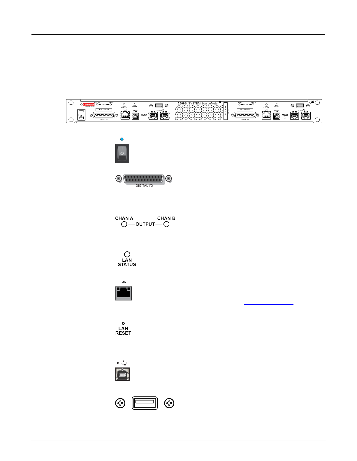
Section
Reference Manual
The power switch turns the instrum ent on or off. The indicator is
Female DB-25 connector. Use a cable equipped with a
output enable pin.
Indicates if the source output is on or off. The source
Illuminates when the instrument is connected to a local area network
page 2-13).
Reverts the LAN settings and the inst r ument password to
USB Type B connection for communication, control, and data
USB Type A connection. You can use a US B flash drive to
also use it to upgrade the firmware.
2: General operation 2606B System SourceMeter® Inst rument
Front panel
The front panel of the 2606B is shown below. The d escriptions of the front-panel controls, USB port,
and indicators follow the figure.
Figure 1: 2606B front panel
Power indicator
and switch
illuminated when the instrument is on. The power switch powers both
modules.
Digital I/O port
male DB-25 connector (Keithley Instruments part number
CA-126-1). Pins provided: Fourteen di gital input or
output pins, seven GND pins, three + 5 V pins, and an
OUTPUT
output for the channel is on when the LE D is illuminated
(blue).
LAN STATUS
indicator
(LAN).
LAN port
RJ-45 connector for a local area network ( LAN). The LAN
interface supports Auto-MDIX, so either a CAT-5e crossover
cable (provided), or a normal CAT-5e straight-through cable
(not provided) can be used. See LAN communications (on
LAN RESET
USB Type B port
USB Type A port
2-2 2606B-901-01 Rev. B / May 2018
default values. Insert a straightened paper clip into the hole
above LAN RESET to reset the LAN. See
LAN
communications (on page 2-13).
transfer. For details, see USB communications (on page 2-9).
store reading buffer data, scripts, and user setups. You can
Page 27

2606B
General operation
TSP-Link System Expansion Interface (on page 6-46).
Channel A
This connector provides input/output connections for
Ground terminal for connecting output HI or LO to
the equipment frame.
Connect the line cord to the power receptacle and a grounded AC
and off (on page 2-6) and Line fuse replac ement (on page A-1).
System SourceMeter® Instrument Reference Manual Section 2:
TSP-Link ports
Rear panel
The rear panel of the 2606B is shown below. Descriptions of rear-panel components follow the figure.
Channel connector
Channel B
Connections for the TSP-Link® system expansion
interface, which test system builders can use to connect
multiple instruments in a master and subordinate
configuration. TSP-Link is a high-speed trigger
synchronization and communicat i on bus. For details, see
Figure 2: 2606B rear panel
HI and LO, sense (S HI/S LO), and guard (G).
Connections are as follows:
LO = LO
S LO = Sense LO
G = Guard
S HI = Sense HI
HI = HI
Ground
Chassis ground
2606B-901-01 Rev. B / May 2018 2-3
Line fuse and power receptacle
Line fuse and
power receptacle
chassis ground. This provides a connection terminal to
power outlet. The line fuse, located jus t above the power
receptacle, protects the power line input of the instrument. For
safety precautions and other detail s , see Turning the instrument on
Page 28

Section
Reference Manual
2: General operation 2606B System SourceMeter® Inst rument
Installing the 2606B
The 2606B is intended for mounting in a rack only. For detailed instructions, refer to the
documentation for the Model 4299-13 Rack Mount K i t (part number 0713574).
Rack mounting the 2606B requires two people. Failure to recognize and observ e stan dard
safety precautions could result in personal injury.
Cooling vents
The 2606B has front and side intakes and rear exhaust vents. All sides must be unobstructed to allow
for air flow and to dissipate heat.
Excessive heat could damage the 2606B and deg rade its performance. Only operate the 2606B in an
environment where the ambient temperature does not exceed 50 °C.
To prevent damaging heat build-up and ensure specified performance, use the following
guidelines.
The rear exhaust vents and both side intake vents, and the front intake vents must be
unobstructed to properly dissipate heat. Even partial blockage could impair proper
cooling.
Do not position any devices adjacent to the 2606B that force air (heated or unheated)
toward its cooling vents or surfaces. This additional airflow could compromise accuracy.
When rack mounting the 2606B, make sure there is adequate airflow around both sides of
the instrument to ensure proper cooling. Adequate airflow enables air temperatures
within approximately one inch of the 2606B surfaces to remain within specified limits
under all operating conditions.
The front and sides of the 2606B are cool air intakes. It is recommended that there is
23 °C ±5 °C air available at these locations. Th e r ear of the 2606B is the exhaust.
If you rack mount high power-dissipation equipment next to the 2606B, it could cause
excessive heating. To produce specified 2606B accuracies, maintain the specified
ambient temperature around the intake vents of the 2606B. In rack configurations with
convection cooling only, which is not recommended, proper cooling practice places the
hottest non-precision equipment (for example, the power supply) at the top of the rack
away from and above precision equipment ( su ch as the 2606B).
Mount precision equipment as low as possible in the rack, where temperatures
are coolest.
2-4 2606B-901-01 Rev. B / May 2018
Page 29
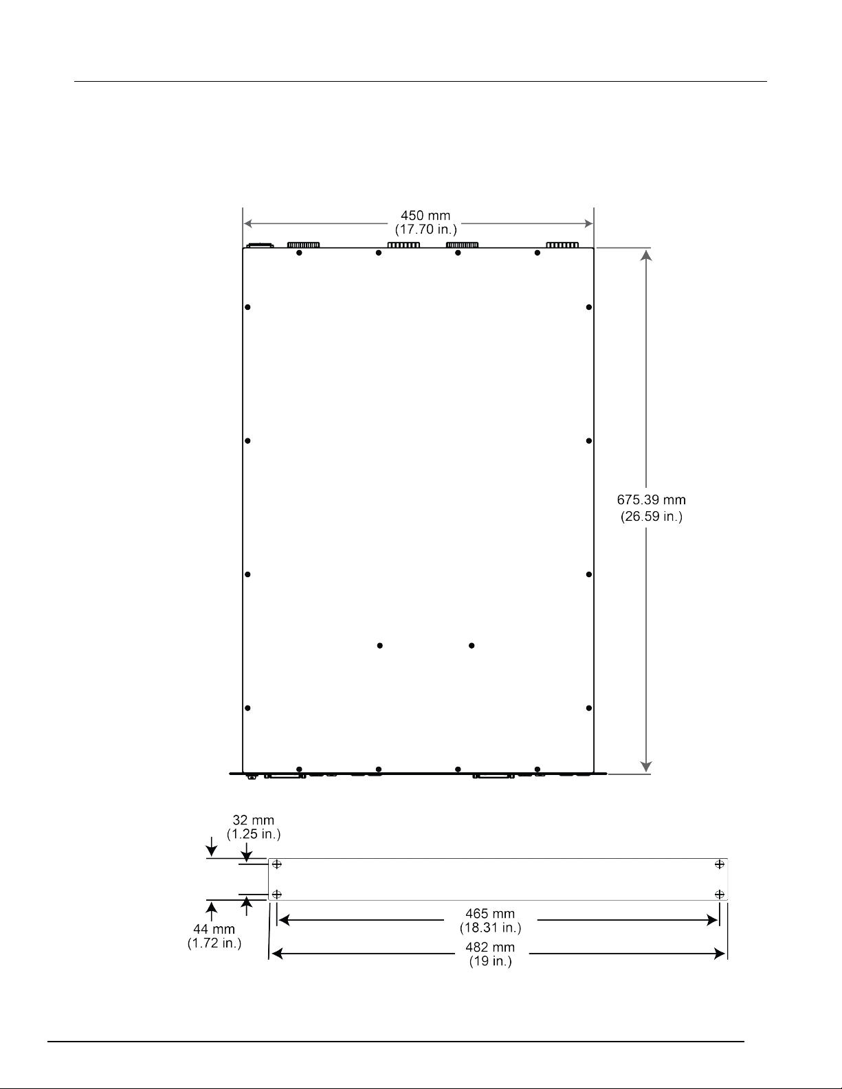
2606B
System SourceMeter® Instrument Reference Manual Section 2: Ge
neral operation
Dimensions
The following figures show the instrument di m ensions.
Figure 3: 2606B dimensions - top view
Figure 4: Dimensions - front view
2606B-901-01 Rev. B / May 2018 2-5
Page 30
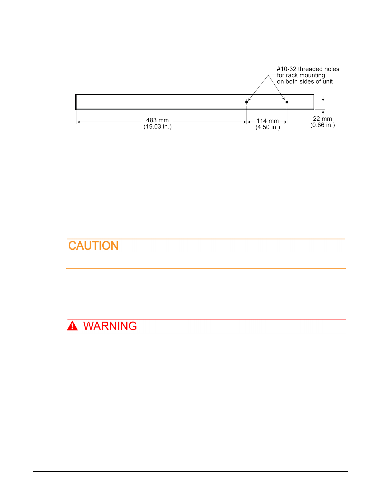
Section
2: General operation 2606B System SourceMeter® Inst rument
Reference Manual
Figure 5: Dimensions - side view
Starting up your instrument
The following topics describe how to power your i nstrument on and off, place the instrument in
standby, configure the line frequency, and replace the line fuse.
Turning the instrument on and off
The 2606B operates from a line voltage of 100 V to 240 V at a frequency of 50 Hz or 60 Hz. Line
voltage is automatically sensed (there are no switches to set). Make sure the operating voltage in
your area is compatible.
Follow the procedure below to connect the 2606B to line power and turn on the instrument.
Operating the instrument on an incorrect line voltage may cause damage to the instrument,
possibly voiding the warranty.
To turn a 2606B on and off:
1. Before plugging in the power cord, make sure that the front panel POWER switch is in the off (O)
position.
2. Connect the female end of the supplied power cord to the AC receptacle on the rear panel.
3. Connect the other end of the power cord to a grounded AC outlet.
The power cord supplied with the 2606B contains a separate protective earth (safety ground)
wire for use with grounded outlets. When proper connections are made, the instrument
chassis is connected to power-line ground through the ground wire in the power cord. In
addition, a redundant protective earth connection is provided through a screw on the rear
panel. This terminal should be connected to a known protective earth. In the ev ent of a
failure, not using a properly grounded protective earth and grounded outlet may result in
personal injury or death due to electric shock.
Do not replace detachable mains supply cords with inadequately rated cords. Failure to use
properly rated cords may result in personal injury or death due to electric shock.
2-6 2606B-901-01 Rev. B / May 2018
Page 31

2606B
General operation
System SourceMeter® Instrument Reference Manual Section 2:
Hazardous voltages may be present on all output and guard terminals. To prevent electrical
shock that could cause injury or death, remove power from the instrument or test system and
discharge any energy storage components (f or example, capacitors or cables) before
changing any connections that might allow contact with an uninsulated co nduct or.
On some sensitive or easily damaged devices under test (DUTs), the instrument power-up or powerdown sequence can apply transient signals to the DUT that may affect or damage it.
When testing this type of DUT, do not make final connections to it until the instrument has completed
its power-up sequence and is in a known operating state. Disconnect it from the instrument before
turning the instrument off.
To prevent any human contact with a live conduct or, connections to the DUT must be fully insulated
and the final connections to the DUT must only use safety-rated safety jack socket connectors that
do not allow bodily contact.
1. To turn your instrument on, press the front panel POWER switch to place it in the on (I) position.
2. To turn your instrument off, press the front panel POWER switch to place it in the off (O) position.
Placing the 2606B in standby
Hazardous voltages may be present on all output and guard terminals. To prevent electrical
shock that could cause injury or death, never make or break connec tions to the 2606B while
the instrument is powered on. Turn off the equipment from the front panel or di sconne ct the
main power cord from the rear of the 2606B before handling cables. Putting the equipment
into standby does not guarantee that the outputs are powered off if a hardware or software
fault occurs.
When the instrument is on, you can place the output i n an act i ve output state (output on) or a standby
mode (output off).
To place the output in standby, send the command:
smuX.source.output = 0
Even though the instrument is placed in standby , the output may not be actually off.
Warmup period
The 2606B must be turned on and allowed to warm u p for at least two hours to achieve rated
accuracies.
2606B-901-01 Rev. B / May 2018 2-7
Page 32

Section
Reference Manual
2: General operation 2606B System SourceMeter® Inst rument
Line frequency configuration
The factory configures the 2606B to automat i cally detect the power line frequency (either 50 Hz or
60 Hz) at each power-up. This detected line frequency is used for aperture (NPLC) calculations.
In noisy environments, you can manually configure the instrument to match the actual line frequency.
To configure the line frequency from the virtual front panel:
1. Press the MENU key, then turn the navigation wheel to select LINE-FREQ, and then press the
ENTER key.
2. Turn the navigation wheel
To configure the instrument to automaticall y detect line frequency at each power-up, select
AUTO.
3. Press the EXIT (LOCAL) key to back out of the menu structure.
To configure the line frequency from a remote interface:
Set the localnode.linefreq or the localnode.autolinefreq attribute. To set the line
frequency to 60 Hz, send:
localnode.linefreq = 60
To configure the instrument to automaticall y detect line frequency at each power-up:
localnode.autolinefreq = true
to select the appropriate frequency and then press the ENTER key.
Fuse replacement
The power receptacle contains a fuse drawer (refer to Rear panel (on page 2-3)). This fuse protects
the power line input of the instrument. If the line fuse needs to be replaced, refer to Line fuse
replacement (on page A-1).
Remote communications interfaces
You can choose from one of several communication interfaces to send commands to and receive
responses from the 2606B.
You can control the 2606B from only one comm unications interface at a time. The first interface on
which the instrument receives a message takes control of the instrument. If another interface sends a
message, that interface can take control of the instrument. You may need to enter a password to
change the interface, depending on the access mo de.
The 2606B automatically detects the type of communications interface when you connect to the
respective port on the instrument. In most ca ses, you do not need to configure anything on the
instrument. In addition, you do not need to reboot if you change the type of interface that is
connected.
The 2606B supports the following remote interfaces:
• LAN. Local area network (LAN) communication s provide the flexibility to build scalable and
functional test or data acquisition systems with a large degree of flexibility.
• USB. Communicate with the instrument over a USB connection.
For more information about the remote int erf aces, see:
• LAN concepts and settings (on page C-1
2-8 2606B-901-01 Rev. B / May 2018
• USB communications (on page 2-9)
)
Page 33

2606B
General operation
System SourceMeter® Instrument Reference Manual Section 2:
Remote interface connections
The remote interface connections are on the f ront panel. Each module has its own set of connections.
Figure 6: Remote interface connections
Output queue
Response messages, such as those generated from print commands, are placed in the output queue.
All remote command interfaces share the same output queue.
The output queue sets the message available (MAV ) bit in the status model.
The data in the output queue is cleared by the *CLS command.
USB communications
To use the front-panel USB port, you must install the Virtual Instrument Software Architecture (VISA)
layer on the host computer. See How to install the Kei thley I/O Layer (on page 2-27
information.
VISA contains a USB-class driver for the USB Test and Measurement Class (USBTMC) protocol that,
once installed, allows the Microsoft Wind ows operating system to recognize the instrument.
When you connect a USB device that implements the USBTMC or USBTMC-USB488 protocol to the
computer, the VISA driver automatically detects the device. Note that the VISA driver only
automatically recognizes USBTMC and USBTMC -USB488 devices. It does not recognize other USB
devices, such as printers, scanners, and storage devices.
In this section, "USB instruments" refers to devices that implement the USBTMC or
USBTMC-USB488 protocol.
) for more
Communicate with the instrument
To communicate with the USB device, you need to use NI-VISATM. VISA requires a resource string in
the following format to connect to the correct US B instrument:
USB[board]::manufacturer ID::model code::serial number[::USB interface
number][::INSTR]
This requires that you determine the paramet ers. You can gather this information by running a utilit y
that automatically detects all instrument s connected to the computer.
If you installed the Keithley I/O Layer, the K eithley Configuration Panel is available from the
Microsoft
2606B-901-01 Rev. B / May 2018 2-9
®
Windows® Start menu in the Keithley Instruments menu.
Page 34

Section
Reference Manual
2: General operation 2606B System SourceMeter® Inst rument
To use the Keithley Configuration Panel to determine the VISA resource string:
1. Start the Keithley Configuration Panel. The Select Operation dialog box is displayed.
2. Select Add.
Figure 7: Select Operation dialog box
3. Click Next. The Select Communication Bus dialog box is displayed.
Figure 8: Select Communication Bus dialog box
4. Select USB.
5. Click Next. The Select Instrument Driver dialog box is displayed.
2-10 2606B-901-01 Rev. B / May 2018
Page 35

2606B
General operation
System SourceMeter® Instrument Reference Manual Section 2:
Figure 9: Select Instrument Driver dialog box
6. Select Auto-detect Instrument Driver - Model.
7. Click Next. The Configure USB Instrument dialog bo x is displayed with the detected instrument
VISA resource string displayed.
8. Click Next. The Name Virtual Instrument dialog box is di splayed.
Figure 10: Name Virtual Instrument dialog box
9. In the Name Virtual Instrument box, enter a nam e that you want to use to refer to the instrument.
10. Click Finish.
2606B-901-01 Rev. B / May 2018 2-11
Page 36

Section
nual
2: General operation 2606B System SourceMeter® Inst rument Reference Ma
11. Click Cancel to close the Wizard.
12. Save the configuration. From the Configuration Utility, select File > Save.
13. In the Keithley Communicator, select File > Open Instrument to open the instrument you just
named.
Figure 11: Keithley Communicator Open an Instrument
14. Click OK.
15. Send a command to the instrument and see if it responds.
Figure 12: Send a command to the instrument
2-12 2606B-901-01 Rev. B / May 2018
Page 37

2606B
General operation
System SourceMeter® Instrument Reference Manual Section 2:
If you have a full version of NI VISA on your system, you can run NI-MAX or the VISA Interactive
Utility. See their documentation for infor m ation.
If you have the Agilent IO Libraries on your syst em , you can run Agilent Connection Expert to check
out your USB instruments. See their docum entation for information.
Connecting multiple USB instruments to the computer
The most convenient way to connect USB instrumentation to the computer is to plug a USB cable
directly from the instrument to the comput er. If you have more than one USB instrument or have other
USB devices, such as printers, keyboards, and m ice, you might not have enough USB connectors on
the computer. To gain more ports, you can use a USB hub or add more USB controller cards if you
have available PCI or PCI Express slots.
LAN communications
The 2606B is an LXI version 1.4 Core 2011 compliant instrument that supports TCP/IP and complies
with IEEE Std 802.3 (ethernet). The LAN ports for the modules a re on the front panel of the 2606B
and support full connectivity on a 10 Mbps or 100 Mbps network.
Through the LAN interface, you can use a web interf ace to control the instrument.
TM
Once the 2606B is connected to the LAN, you can use the LXI
addresses of instruments that are connected t o the LAN and that support the VXI-11 discovery
protocol. You can also manually set up the IP address.
Discovery Tool to identify the IP
For information about setting up a LAN interface, refer to LAN concepts and settings (on page C-1
).
LAN cable connection
Use a LAN crossover cable (RJ-45, male to male) or a st raight-through cable to connect your
equipment. The 2606B includes a cable that y ou can use for the TSP-Link
communications. The instrument automat icall y senses which cable you have connected.
The following figure shows the location of t he LAN port on the front panel of the instrument. Connect
the LAN cable between this connection and the LA N port on the computer.
Figure 13: LAN connection
®
network or LAN
2606B-901-01 Rev. B / May 2018 2-13
Page 38

Section
Reference Manual
1
LED indicates the LAN port is connected to a 100 Mbps network
2
LED indicates the LAN port is connected to a 10 Mbps network
Off
is not connected
On
is connected
Blinking
is sending or receiving data
1024
VXI-11
5025
Raw socket
2: General operation 2606B System SourceMeter® Instrument
LAN status LEDs
The figure below illustrates the two status light emitting diodes (LED) that are on the LAN port of the
instrument. The table below the figure prov i des explanations of the LED states.
Figure 14: LAN status
When the LED is: The network:
Using the LAN with remote operations
The following table lists the 2606B remote interf ace's available LAN protocols:
LAN protocols
Port number Protocol
23 Telnet
5030 Dead socket termination port
You can only use one remote interface at a time. Although multiple ethernet connections to the
instrument can be opened, only one can be us ed to control the instrument at a time.
Raw socket: Raw socket is a basic ethernet connection that communicates similarly to RS-232
without explicit message boundaries. The instrument will always terminate messages with a line f eed,
but because binary data may include bytes that resemble line feed characters, it may be difficult t o
distinguish between data and line feed characters.
VXI-11: VXI-11 is similar to GPIB and supports message boundaries and service requests (SRQs). A
VXI-11 driver or VISA software is required. Test Script Builder (TSB) uses VISA and can be used with
the VXI-11 interface.
Telnet: Telnet is similar to raw socket and is used when you need to interact directly with the
instrument, typically for debugging and troubleshooting. Telnet requires a separate telnet program .
Dead socket termination port: The dead socket termination po rt i s us ed to terminate all existing
LAN connections. A dead socket is one that is held open by the instrument because it has not been
properly closed. This most often happens when the computer is turned off or reboots without first
closing the socket. This port cannot be used for command and control functions.
Monitoring the LAN
The lan.autoconnect command configures the instrument t o m oni tor the LAN for lost connections.
All ethernet connections are disconnected if t he LA N li nk is disconnected for longer than the time-out
value specified in the lan.linktimeout attribute.
2-14 2606B-901-01 Rev. B / May 2018
Page 39

2606B
General operation
System SourceMeter® Instrument Reference Manual Section 2:
2606B web interface
The 2606B web interface allows you to review inst rument status, control the instrument, and upgrade
the instrument over a LAN connection.
The instrument web page resides in the firmware of the instrument. Changes you make through the
web interface are immediately made in the instr um ent.
The web page includes:
• Instrument status.
• The instrument model, serial number, firmware revision, and the last LXI message.
• An ID button to help you locate the instrument.
• A virtual front panel and command interface that you can use to control the instrument.
• Administrative options and LXI information.
• A link to TSB Embedded, which allows script-building functionality and single-line commands.
• A link to TSP
The instrument web page resides in the firmware of the instrument. Changes you make through the
web interface are immediately made in the instrument.
Many of the options on the web interface require t he web browser plug-in Java
Environment. The latest version of the plug-in i s av ai l able from the Java download site
(http://www.java.com/en/download/manual.jsp). The instrument web interface uses Java applets and,
depending on your browser security settings, m ay require your permission to download and install
them.
To connect to the instrument web interface, y ou m ust have a LAN connection from the computer to
the instrument. See LAN concepts and setting s (on page C-1
Once the 2606B is connected to the LAN, you can use the LXITM Discovery Tool to identify the IP
addresses of instruments that are connected t o the LAN and that support the VXI-11 discovery
protocol. You can also manually set up the IP address.
®
Express, which is a utility that creates runnable scripts.
) for more information.
TM
SE Runtime
Connecting to the instrument through the web interface
When the LAN and instrument establish a connecti on, you can open the web page for the instrument.
To access the web interface:
1. Open a web browser on the host computer.
2. Enter the IP address of the instrument in the address box of the web browser. For example, if the
instrument IP address is 192.168.1.101, enter 192.168.1.101 in the browser address box.
3. Press Enter on the computer keyboard to open the instrument we b page.
If prompted, enter a user name and password. The default is admin for both.
If the web page does not open in the browser, see LAN troubleshooting suggestions (on page 8-6).
To set up LAN connections and find the IP address, see LAN concepts and settings (on page C-1).
2606B-901-01 Rev. B / May 2018 2-15
Page 40

Section
Reference Manual
2: General operation 2606B System SourceMeter® Inst rument
Web interface Welcome page
The Welcome page of the module provides information about the module. It includes:
• The model number, manufacturer, serial number, and firmware revision number of the module.
• The communications information for the module.
• The ID button, which allows you to identify the module. Refer to Identify the instrument
2-16).
Figure 15: Web interface Welcome page
(on page
Identify the instrument
If you have a bank of instruments, you can select the ID button to determine which module you are
communicating with.
Before trying to identify the instrument module, make sure you have a remote connection to t he
module.
To identify the instrument module:
1. On the Home page, select the ID button. The button turns green a nd the LAN STATUS indicator
on the module blinks.
2. Select the ID button again to return the button to its original color and return the LAN STATUS
2-16 2606B-901-01 Rev. B / May 2018
indicator to steady on.
Page 41

2606B
General operation
System SourceMeter® Instrument Reference Manual Section 2:
Change the IP configuration through the web interface
You can change the LAN settings, such as IP addr ess, subnet mask, gateway, and DNS address,
through the web page of the instrument.
If you change the IP address through the web page, the web page tries to redirect to the IP address
that is configured in the instrument. In some cases, this may fail. This generally happens if you switch
from IP address assignment that uses a static address to IP address assignment that uses a DHCP
server. If this happens, you need to revert t o ei ther using the virtual front panel to set the IP address
or use an automatic discovery tool to determine the new IP address.
You can also change the IP configuration using TSP and SCPI commands. See LAN concepts and
settings (on page C-1) for information.
To change the IP configuration using the instrument web page:
1. Access the internal web page as described in Connecting to the instrument through the web
interface (on page 2-15).
2. From the navigation bar on the left, select IP Configuration.
3. Click Modify. The Modify IP Configuration page is di splayed.
Figure 16: 2606B Modify IP Configuration screen
2606B-901-01 Rev. B / May 2018 2-17
Page 42

Section
Reference Manual
2: General operation 2606B System SourceMeter® Inst rument
4. Change the values.
5. Click Submit. The instrument reconfigures its settings, which m ay take a few moments.
You may lose your connection with the web interface after clicking Submit. This is normal and does
not indicate an error or failure of the operation. If this occurs, find the correct IP address and reopen
the web page of the instrument to continue.
Change the password through the web interface
You can change the instrument password from the web interface.
The default user name and password is admin.
To change the password:
1. From the web interface Welcome page, select Set Password.
2. In the Current password box, enter the presently used pas sword.
3. In the New Password and Confirm New Password boxes, enter the new password.
4. Click Submit.
Use TSB Embedded
TSB Embedded is a tool with a reduced set of feat ures compared to the Keithley Test Script Builder
(TSB) software. TSB Embedded allows both script -building functionality and console functionality
(single-line commands).
For more information on TSB Embedded, refer to Working with TSB Embedded (on page 6-36
).
Virtual Front Panel
The Virtual Front Panel page allows you to control the instrument from a computer as if you were
using an instrument with a display and keyboar d. You can operate the instrument using a mouse to
select options.
The 2606B only allows fewer than three clients t o open the virtual front panel web page at the same
time. Only the first successfully connected client can operate the instrument. Other clients c an only
view the virtual front panel.
2-18 2606B-901-01 Rev. B / May 2018
Page 43

2606B
on
Power switch. The in position turns the 2606B on (I); the out position turns it off (O).
Toggles between the source-measure display and the user message display.
Configures a function or operation.
SRC
for editing.
MEAS
edit (V, A, or W).
MODE
Selects a meter mode (I-METER, V-METER, OHM-METER, or WATT-METER).
System SourceMeter® Instrument Reference Manual Section 2: General operati
Virtual front panel options
The virtual front panel of the 2606B is shown belo w. The descriptions of the controls and indicators
follow the figure.
Figure 17: Virtual front panel options
1. Power switch, display and configuration keys
This is for display only on the virtual front panel.
2. SMU setup, performance control, special operation, and numbers
SMU (source-measure unit) setup
Selects the source function (voltag e or current) and places the cursor in the source field
Cycles through measure functions (V, A, Ω, or W).
LIMIT
Places the cursor in the compliance limit field for editing. Also selects t he limit value to
2606B-901-01 Rev. B / May 2018 2-19
Page 44

Section
Reference Manual
DIGITS
Sets the display resolution (4½, 5½ , or 6½ digits).
SPEED
Sets the measurement speed (FAST, MEDium, NORMAL, HI-ACCURACY, or OTHER).
(on page 2-76).
REL
Controls relative measurements, which allows a baseline value to be subtracted from a
reading.
FILTER
Enables or disables the digital filter. You can use this filter to reduce reading noise.
LOAD
Loads test for execution (FACTORY, USER, or SCRIPTS).
RUN
Runs the last selected factory or user-defined test.
STORE
include measurements, source values, and timestamp values, if configur ed.
RECALL
Recalls information (DATA or STATISTICS) stored in a reading buffer: DA TA includes
includes MEAN, STD DEV, SAMPLE SIZE, MINIMUM, MAXIMUM, PK-PK.
TRIG
Triggers readings.
MENU
many functions and features.
EXIT
Cancels the selection and returns to the previous menu or display. Also used as a
ENTER
Accepts the selection and moves to t he next choice or exits the menu.
When enabled and in EDIT mode, the number keys (0-9, +/-, 0000) allow direct numeric
Turn the navigation wheel to:
Select a menu option or a value
2: General operation 2606B System SourceMeter® Inst rument
Performance control
Speed and accuracy are set by controlling the measurement aperture. Also s ee Speed
Special operation
Accesses reading buffers and takes readings. TAKE_READINGS: Use to t ake readings
and store them in a reading buffer. SAVE: Use to save a reading buffer to nonvolatile
memory or to a user-installed flash drive (USB1) in CSV or XML format. Read ings
stored readings, and if configured, source values and timestamp values; S TATISTICS
Accesses the main menu (on page 2-29). The main menu can be used to configure
LOCAL key to take the instrument out of rem ote operation.
Numbers
Number keys
entry. Press the navigation wheel to enter EDIT m ode. For more information, see
Setting a value (on page 2-32
).
3. Navigation wheel
Move the cursor to the left and the right ( the cursor indicates the selected value
or item)
While in edit mode, increase or decr ease a selected source or compliance val ue
Push the navigation wheel to:
Enable or disable edit mode for the selec ted source or compliance value
Open menus and submenu items
2-20 2606B-901-01 Rev. B / May 2018
Page 45

2606B
General operation
Use the CURSOR keys to move the cursor left or right. When the cursor is on the
wheel to view the value or sub-menu it em .
When enabled and in EDIT mode, the number keys (0-9, + /-, 0000) allow direct numeric
Opens the Reading Buffers application, which you can use to download and sav e data
from the reading buffers.
Turns the source output on or off.
Selects the next higher source or m eas ure range.
Selects the next lower source or measure range.
In addition to selecting range func tions, the up and down range keys change t he format
for non-range numbers (as an example, when editing the limit value).
System SourceMeter® Instrument Reference Manual Section 2:
4. Cursor keys
source or compliance value digit, press the navigation wheel to enter edit mode, and
turn the navigation wheel to edit the value. Press the navigation wheel agai n when you
finish editing.
Use the CURSOR keys or the navigatio n wheel to move through menu items. To v i ew a
menu value, use the CURSOR keys for cursor control, and then press the navigati on
5. Numeric Entry
entry. Press the navigation wheel to enter EDIT m ode. For more information, see
Setting a value (on page 2-32
).
6. Recall Buffer
7. Output control
8. Range keys
Enables or disables source or meas ur e autorange.
2606B-901-01 Rev. B / May 2018 2-21
Page 46

Section
Reference Manual
Instrument is in editing mode
Questionable reading or invalid calibration step
Instrument is in remote mode
Instrument is addressed to listen
Service request is asserted
Digital filter is enabled
Source or measure autorange is selec ted
2: General operation 2606B System SourceMeter® Inst rument
Display indicators (not shown)
The items listed below represent the possible display indicators and their meanings.
Indicator Meaning
EDIT
ERR
REM
TALK
Instrument is addressed to talk
LSTN
SRQ
REL
Relative mode is enabled
FILT
AUTO
* (asterisk)
Readings are being stored in the buffer
Flash Upgrade
Allows you to upgrade the firmware for the module from the web interface. See Upgrading the
firmware (on page A-2) for details.
TSP Express
The TSP® Express tab provides access to the TSP Express Launch page. From this page, click the
Launch button to start TSP Express.
Only one web application can be running and connected to the instrument at a time. TSP Express
will not run if another web application, such as TSB E m bedded, Reading Buffers, or Flash Upgrade,
is running and connected to the instrument. If you need to run another web application, be sure to
close TSP Express before starting the other web application.
To run TSP Express:
1. From the navigation area on the left side of the web interface, select TSP Express. The TSP
Express page is displayed.
2. Click the Launch button. The TSP Express window opens.
3. There is a help pane on the right side of the TSP E xpress main window. You can adjust the width
of the help pane by sliding the vertical bar. Click and follow the step-by-step example in the help
pane to become familiar with TSP Express (there i s a link to the example in the TSP Express
Introduction's first paragraph).
2-22 2606B-901-01 Rev. B / May 2018
Page 47

2606B
General operation
System SourceMeter® Instrument Reference Manual Section 2:
Figure 18: TSP Express
Review events in the event log
The event log records all LXI events that the inst rument generates and receives. The log includes the
following information:
• The EventID column, which shows the identifier of the event that generated the event message.
• The System Timestamp column, which displays the seco nds and nanoseconds when the event
occurred.
• The Data column, which displays the text of the event message.
To clear the event log and update the information on the screen, select the Refresh button.
Supplied software
The majority of software applications an d al l inst rument drivers from Keithley Instruments de pend on
some, or all, of the following software components:
• NI-VISA
• VISA shared components
• IVI shared components
• NI
• NI
Keithley instrument driver
TM
TM
CVITM runtime engine
TM
IVITM compliance package
These software components are available for download from the Product Support web page
(https://www.tek.com/product-support).
2606B-901-01 Rev. B / May 2018 2-23
Page 48

Section
Reference Manual
2: General operation 2606B System SourceMeter® Inst rument
Instrument driver types
There are several different styles of instrument drivers. Keithley Instruments provides three diff erent
instrument drivers for the 2606B: A native LabVIEW driver, an IVI-C driver, and an IVI-COM driver.
You need to pick the style that best suits the application development environment (ADE) that you are
using. For example, if you are using LabVI EW, you would pick a native LabVIEW driver. If a native
LabVIEW driver is not available then you can use an IVI-C driver as LabVIEW has the option of
creating a wrapper for the IVI-C driver.
LabVIEW supports IVI-COM drivers but they are definitely not the first or second choice. However, if
they are the only driver types for the instrument, they can be used.
If LabWindows/CVI or C/C++ is your programmi ng l anguage, an IVI-C driver is the best option. For
Microsoft
®
Visual Basic® 6.0 and any .NET language (C#, VB.NET, and so on), an IVI-COM driver is
the best option.
Sometimes instrument vendors do not provide al l three driver types. Most languages can
accommodate other driver types, but this is not optimal.
The following sections describe the different driver types in more detail.
VXIPnP drivers
VXI (Vixie) plug-and-play (VXIPnP) style drivers are Win32 DLLs that have some standard functions
defined by the VXIPnP Alliance, such as:
• init
• close
• error_message
• reset
• self_test
• Read
• Initiate
• Fetch
• Abort
The application programming interface (AP I) was defined so that users of instruments would have a
familiar API from instrument to instrument. There are some basic guidelines when creating APIs f or
your instrument, such as using VISA data types and how to construct the CVI hierarchy.
2-24 2606B-901-01 Rev. B / May 2018
Page 49

2606B
General operation
System SourceMeter® Instrument Reference Manual Section 2:
LabVIEW drivers
Native LabVIEW drivers
TM
A native LabVIEW
it does not make any calls to external DLLs or Lib rary files. This makes the driver portable to all the
platforms and operating systems that La bV IEW and VISA supports (currently, Linux
®
X, and Microsoft® Windows®).
OS
National Instruments (NI
driver is a LabVIEW driver that is created using enti rely built-in LabVIEW VIs —
®
on x86, Mac
TM
) maintains a native LabVIEW driver style guide
(http://zone.ni.com/devzone/cda/tut/p/id/3271).
LabVIEW driver wrappers
All IVI-C drivers have a function panel file (.fp) that shows a hierarchy of the function calls into a DLL.
It is a tool that guides a user to select the correct function call in the driver, since a DLL only has a flat
API entry point scheme (unlike COM or .NET). Any CVI-generated .fp file can be imported into
LabVIEW and LabVIEW will generate a wrapper for the DLL. The drawback here is that the driver is
dependent on the DLL, which is not portable and is therefore Windows-specific.
Getting instrument drivers
To see what drivers are available for your instrument:
1. Go to the Product Support web page (https://www.tek.com/product-support).
2. Enter the model number of your instrument .
3. Select Software from the list.
4. Select and download the file.
TM
For LabVIEW
driver database.
, you can also go to the National Instruments website and search their instrument
Instrument driver examples
All Keithley drivers come with examples writt en i n several programming languages that show you how
to do the most common things with the instruments.
®
The examples are in the Microsoft
Windows® Start menu, under Keithley Instruments > Model
Number (where Model Number is the instrument model number).
IVI shared components
The IVI shared components are a similar concept to the VISA shared components. The IVI
Foundation provides class drivers for:
• All the supported instruments (DMM, Scope, Fgen, and so on)
• The configuration store
The IVI shared components also create the inst al lation folders and registry keys that all IVI drivers
and support files use for installation.
2606B-901-01 Rev. B / May 2018 2-25
Page 50

Section
Reference Manual
2: General operation 2606B System SourceMeter® Instrument
Interchangeable Virtual Instruments (IVI) style drivers
The major problem with VXIPnP drivers was that the API was not specific to the instrument. For
something as standard as measuring DC volts on a digital multimeter (DMM), it would be a good idea
if there were a set of standard functions to do t hi s.
The IVI Foundation (http://www.ivifoundation.org
) defined a set of application programming interfaces
(APIs) for the following instruments: DM M , function generator, DC power supply, scope, swit ch,
spectrum analyzer, RF signal generator and power meter. They are currently working on class APIs
for some other instrument types.
There are two types of IVI drivers: IVI-COM drivers use Microsoft® COM technology to expose driver
functionality, while IVI-C drivers use conventional Microsoft
®
Windows® DLLs to export simple C-
based functions.
For more information about IVI drivers and the differences between the COM, C, and .NET interfaces,
see Understanding the Benefits of IVI
(http://www.ivifoundation.org/docs/Understanding%20the%20Benefits%20of%20IVI[3].pdf).
NI CVI runtime engine
IVI-C drivers that are created using National Instruments (NITM) LabWindows/CVI environment
depend on either the CVI runtime (cvirte.dl l ), or the instrument support run-time (instrsup.dll), and
must be present on the system for them to run.
NI IVI Compliance Package
The National Instruments (NITM) IVI Compliance Package is a software package that contains IVI
class drivers and support libraries that are nee ded for the development and use of applications that
leverage IVI instrument interchangeability. The IVI Compliance Package also is based on and is
compliant with the latest version of the instru m ent programming specifications defined by the I VI
Foundation.
The NI ICP installer installs the IVI share d components, CVI runtime engine, and the instrument
support runtime engine.
Keithley I/O layer
The Keithley I/O Layer (KIOL) is a software pa ckage that contains several utilities and drivers. It is
mainly used as a supplement to IVI drivers or appli cation software like Test Script Builder (TSB).
The KIOL contains:
TM
• NI-VISA
• Keithley Configuration Panel
• Keithley Communicator
NI-VISA Runtime
NI-VISATM is National Instruments (NITM) implementation of the VISA standard. There are two
versions: a full version and a run-time version. The Keithley I/O Layer (KIOL) contains a licensed
version of the NI-VISA Run-Time Engine that contains only the binary files (DLLs) that allow the NIVISA drivers to operate.
If you already have NI software (such as LabVIEW™ or LabWindows™) installed, you have a valid
license that can be used with Keithley drivers and app l i cat i on software.
If you do not have NI software installed, you must i nstall the KIOL to install the drivers.
Runtime-Time Engine
2-26 2606B-901-01 Rev. B / May 2018
Page 51

2606B
General operation
System SourceMeter® Instrument Reference Manual Section 2:
Keithley Configuration Panel
The Keithley Configuration Panel is a configuration utility for IVI drivers, similar to NI-MAX. It can also
autodetect USBTMC instruments and LAN inst ruments that support the VXI-11 protocol.
Keithley Communicator
The Keithley Communicator is a dumb terminal program that uses VISA to communicate with the
instrument.
How to install the Keithley I/O Layer
Before installing, it is a good practice to check the Product Support web page
(https://www.tek.com/product-support) to see if a later version of the Keithley I/O Layer is available.
Search for Keithley I/O Layer.
You can download the Keithley I/O Layer from t he Keithley website.
The software installs the following components:
®
• Microsoft
TM
• NI
• NI-VISA
• Keithley SCPI-based Instrument IVI-C driver
• Keithley I/O Layer
To install the Keithley I/O Layer from the Keithley website:
1. Download the Keithley I/O Layer Software from the Product Support web page
(https://www.tek.com/product-support), as described above. The software is a single compressed
file and should be downloaded to a temporary directory.
2. Run the downloaded file from the temporary direct ory.
3. Follow the instructions on the screen to install t he software.
4. Reboot your computer to complete the installat i on.
.NET Framework
IVI Compliance Package
TM
Run-Time Engine
2606B-901-01 Rev. B / May 2018 2-27
Page 52

Section
Reference Manual
2: General operation 2606B System SourceMeter® Inst rument
System information
You can retrieve serial number, firmware revision, and calibration dates from the instrument.
To view the system information from the virtual front panel:
1. Press the MENU key.
2. Select SYSTEM-INFO.
3. Select one of the following:
FIRMWARE
SERIAL#
CAL
MEMORY-USAGE
To retrieve system information from a remote interface:
To retrieve the firmware revision and serial number, send the *IDN? query (see Identification query:
*IDN? (on page D-3) for more information).
To determine memory usage, see the meminfo() (on page 7-147) function.
To determine when calibration was last run, see smuX.cal.date (on page 7-178).
Menu overview
To determine when calibration is due, see smuX.cal.due (on page 7-179).
The following topics describe how to work with t he virtual front panel menus.
Menu navigation
To navigate through the menus and submenus, the 2606B m ust not be in edit mode (the EDIT
indicator is not illuminated).
Selecting menu items
To navigate the Main and Configuration menus, use the editing keys as follows:
• Press either CURSOR arrow key to highlight an option.
• Rotate the navigation wheel
• Press the ENTER key (or the navigation wheel
• Use the EXIT (LOCAL) key to cancel changes or to return to the previous menu or display.
For quick menu navigation, turn the navigat i on wheel to highlight an option and then press the
navigation wheel
(clockwise or counter-clockwise) to highlight an opt ion.
) to select an option.
to select the highlighted option.
2-28 2606B-901-01 Rev. B / May 2018
Page 53

2606B
General operation
System SourceMeter® Instrument Reference Manual Section 2:
Menu trees
You can configure instrument operation throu gh the menus that are accessed from the virtual front
panel.
Main menu
The main menu structure is summarized in the following figure and table. For other menu items, see
Configuration menus (on page 2-30
Figure 19: 2606B main menu tree
).
2606B-901-01 Rev. B / May 2018 2-29
Page 54

Section
Reference Manual
SCRIPT
Saves and recalls user scripts
Manage scripts (on page 6-3)
- SAVE
Saves scripts
SETUP
Saves and recalls user and factory setup
options
Saved setups (on page 2-52)
- SAVE
Saves user setup options
- RECALL
Recalls user setup options
- POWERON
Sets the configuration used durin g startup
LAN
Configures the local area network ( LA N )
LAN concepts and settings (on page
- STATUS
Displays LAN connection status
- CONFIG
Configures the LAN IP address and gateway
- APPLY_SETTINGS
Applies changes made using the CONFIG
menu
- RESET
Restores the default settings
- ENABLE
Enables and disables the LAN interfac e
TSPLINK
network
- NODE
Selects the instrument node identi fier
- RESET
Resets the TSP-Link network
UPGRADE
Upgrades the firmware from a USB flash drive
Upgrading the firmware (on page A-2)
DIGOUT
Controls digital outputs
Digital I/O (on page 3-78)
- DIG-IO-OUTPUT
Selects the digital I/O values
- WRITE-PROTECT
Write-protects specific digital I/O lines
BEEPER
Controls the key beeps
General operation (on page 2-1)
- ENABLE
Enables the key beeps
- DISABLE
Disables the key beeps
LINE-FREQ
Configures the line frequency
General operation (on page 2-1)
- 50Hz
Set the line frequency to 50 Hz
- 60Hz
Set the line frequency to 60 Hz
- AUTO
Enables automatic line freque ncy detection
SYSTEM-INFO
Displays the system information
General operation (on page 2-1)
- FIRMWARE
Displays the version of firmware installed
- SERIAL#
Displays the serial number of the unit
- CAL
Displays the last calibration date
- MEMORY-USAGE
Displays memory usage in percentage
RESET-PASSWORD
34)
2: General operation 2606B System SourceMeter® Inst rument
The following table contains descriptions of the main menu options and cross-references to related
information. To access a menu option, press the MENU key, turn the navigation wheel
cursor to select an item, and press the navigation wheel
Menu selection Description For more information, see:
- LOAD Loads scripts into nonvolatile m emory
.
C-1)
to move the
Configure the instrument in a T SP-Link®
during start up
Resets the system password
TSP-Link system expansion interfac e
(on page 6-46)
Password management (on page
6-
Configuration menus
The configuration menu structure is summ arized in the following figure and table. For directions on
navigating the menu, see Menu navigation (on page 2-28). For other menu items, see Main menu
page 2-29).
2-30 2606B-901-01 Rev. B / May 2018
(on
Page 55

2606B
General operation
System SourceMeter® Instrument Reference Manual Section 2:
Figure 20: 2606B CONFIG menu tree
2606B-901-01 Rev. B / May 2018 2-31
Page 56

Section
Reference Manual
V-source sense, low range; I-source
low range; and highC mode
Range (on page 2-71), Basic source-
measure procedure (on page 2-39)
sense, low range; autozero
measure procedure (on page 2-39)
V-source and I-source compliance
limits
Limits (on page 2-35)
Measurement speed (NPLC)
Speed (on page 2-76)
Relative values
Relative offset (on page 3-1)
Buffer count and destination
Source-measure concepts (on page 4-
1)
2: General operation 2606B System SourceMeter® Inst rument
Press the EXIT key to return to a previous menu.
The following table contains descriptions of the configuration menus with cross references to r el ated
information.
To select a menu:
1. Select the CONFIG key.
2. Select CHANNEL-A, CHANNEL-B, or COMMON. COMMON accesses settings for TRIG and
STORE.
3. Select the key associated with the menu.
To access, select: Options For more information, see:
SRC
MEAS
LIMIT
SPEED
REL
FILTER
OUTPUT ON/OFF
TRIG
STORE
V and I-measure range, V-measure
Control digital filter Filters (on page 3-3)
Off-state, control digital I/O Output-off states (on page 2-65)
Trigger in, count, interval, an d delay Triggering (on page 3-30
Range (on page 2-71), Basic source-
)
Setting a value
Through the virtual front panel, you can adjust a val ue using the Navigation wheel and the keypad.
To adjust a value:
1. Use the CURSOR arrow keys or the navigation wheel to move the cursor to the digit that needs
to be changed.
2. Select the navigation wheel
illuminated.
3. Rotate the navigation wheel
the cursor moves to the next digit on the right.
4. Select the ENTER key to select the value or press the EXIT (LOCAL) key to cancel the change.
5. To return to the main menu, press the EXIT (LOCAL) key.
or the ENTER key to enter edit mode. The EDIT indicator is
or use the number pad to set the value. If you use the number pad,
To set an option to zero (if it is an option for the ent ry ), select the 0000 numeric entry key. To toggle
the polarity of a value, press the +/– numeric entry key.
2-32 2606B-901-01 Rev. B / May 2018
Page 57

2606B
System SourceMeter® Instrument Reference Manual Section 2:
General operation
Setting source and compliance values
When the 2606B is in the edit mode (EDIT indicator i s on), the editing controls are used to set source
and compliance values. Note that when you edit the source value, source autoranging is turned off
and remains off until you turn it on again.
To cancel source editing, press the EXIT (L OCAL) key.
To edit the source value:
1. Press the SRC key. The cursor flashes in the source val ue field.
2. Use the CURSOR keys (or turn the navigation wheel
to be changed.
3. Press the navigation wheel
illuminated.
4. Change the source value (see Setting a value (on page 2-32
The +/- key toggles the polarity. The 0000 key sets the value to 0.
or the ENTER key to edit the source value. The EDIT indicator is
) to move the cursor to the digit that needs
)).
Beeper
5. When finished, press the ENTER key (the EDIT indicator is not illuminated).
To edit compliance limit values:
1. Press the LIMIT key.
2. Select the type of compliance.
3. Press the navigation wheel or the ENTER key to enter edit mode. The EDIT indicator is
illuminated.
4. Change the compliance value (see Setting a value (on page 2-32)).
5. When finished, press the ENTER key (the EDIT indicator is not illuminated).
The up and down range keys change the format of the limit value.
The 2606B includes a beeper. When it is enabled, a beep indicates one of the following actions have
occurred:
• A virtual front-panel key was pressed: A short beep, similar to a key click, is issued.
• The navigation wheel
• The output source was changed: A longer beep is issued when you select the OUTPUT ON/
c
ontrol (turn the output on or off).
was turned or pressed: A short beep is issued.
OFF
2606B-901-01 Rev. B / May 2018 2-33
Page 58

Section
Reference Manual
2: General operation 2606B System SourceMeter® Inst rument
To turn the beeper on or off from the virtual front panel:
1. Press the MENU key, and then select BEEPER.
2. Select one of the following:
ENABLE
DISABLE
To turn the beeper on or off from the TSP command interface:
Set the beeper.enable attribute. For example, to enable the beeper, send:
beeper.enable = 1
Display mode
Use the DISPLAY key to scroll through the various display modes shown in the figure below. Refer to
Display operations (on page 3-66
) for more information about the display.
Figure 21: Display modes
2-34 2606B-901-01 Rev. B / May 2018
Page 59

2606B
General operation
System SourceMeter® Instrument Reference Manual Section 2:
Basic operation
Hazardous voltages may be present on all output and guard terminals. To prevent electrical
shock that could cause injury or death, never make or break connections to the 2606B while
the instrument is powered on. Turn off the equipment from the front panel or di sconne ct the
main power cord from the rear of the 2606B before handling cables. Putting the equipment
into standby does not guarantee that the outputs are powered off if a hardware or software
fault occurs.
Before you begin any of the following front panel procedures, make sure that you exit out of the
menu structure. Press the EXIT (LOCAL) key as many times as n eeded to return to the main
display.
Source-measure capabilities
From the virtual front panel, you can configure t he i nstrument to perform the following sourcemeasure operations:
• Source voltage: Measure and display current, voltage, resistance, or power
• Source current: Measure and display voltage, curren t, resistance, or power
• Measure resistance: Display resistance calculated from voltage and current components of
measurement (can optionally specify source v ol tage or source current value)
• Measure power: Display power calculated f rom voltage and current components of
measurement (can optionally specify source v ol tage or source current value)
• Measure only (V or I): Display voltage or current measurement
Limits
When sourcing voltage, the 2606B can be set to l im i t current or power. Conversely, when sourcing
current, the 2606B can be set to limit volt age or power. In steady-state conditions, the 2606B output
will not exceed the limit. The maximum limit is the same as the maximum values listed in the
specifications.
The limit circuit limits in either polarity re gardless of the polarity of the source or limit value. The
accuracy of the limit opposite in polarity from the source is diminished. The maximum limits are based
on the source range. For more information, see Limit principles (on page 4-1
The limit operation of the instrument changes dependent on the source mode (current or voltage),
load, and the configured limits (current, voltage, and power). As the names imply, the current limit
restricts the current for sourced voltage and the voltage limit restricts the voltage for a sourced
current. The power limit, however, restricts power by lowering the present limit in effect (voltage or
current) as needed to restrict the SMU from exceeding the specified power limit. For additional details
on using limits, including load considerations when specifying both a current (or a voltage) limit and a
power limit, see Operating boundaries (on page 4-3
).
).
The following topics describe how to set the l i m i ts.
2606B-901-01 Rev. B / May 2018 2-35
Page 60

Section
Reference Manual
smuX.source.limiti = limit
Set current limit.
smuX.source.limitv = limit
Set voltage limit.
smuX.source.limitp = limit
Set power limit.
compliance = smuX.source.compliance
Test if in limit (true = in limit; false = not in limit).
2: General operation 2606B System SourceMeter® Inst rument
Virtual front-panel limit
To set the limit from the virtual front panel:
1. Select the LIMIT key for the channel.
2. Select CURRENT, VOLTAGE, or POWER as needed.
3. Select the ENTER key.
4. Use the navigation wheel
to set the new value.
5. Press the ENTER key.
6. Press the EXIT (LOCAL) key to return to the main display.
Remote limit
The table below summarizes basic commands to pro gram a l i m it. For a more complete description of
these commands, refer to the TSP command referen ce (on page 7-1
Limit commands
Command Description
).
To set the limit, send the command with the lim i t value as the parameter. The following programming
example illustrates how to set the current, voltage, and power limit to 50 mA, 4 V, and 1 W
respectively:
smua.source.limiti = 50e-3
smua.source.limitv = 4
smua.source.limitp = 1
The following programming example illustrat es how to print the limit state:
print(smua.source.compliance)
A returned value of true indicates one of three thing s:
• If the instrument is configured as a current sou rce, the voltage limit has been reached
• If the instrument is configured as a voltage source, the current limit has been reached
2-36 2606B-901-01 Rev. B / May 2018
Page 61

2606B
General operation
System SourceMeter® Instrument Reference Manual Section 2:
Fundamental circuit configurations
The fundamental source-measure configuration s for the 2606B are shown in the following figure.
When sourcing voltage, you can measure current or voltage (see A: Source V). When sourcing
current, you can measure voltage or current (see B: Source I). See Basic circuit configurations
page 4-12) for detailed information.
Figure 22: Fundamental source-measure configurations
(on
Operation considerations for the ADC
The following paragraphs discuss autozero and NPLC caching.
Autozero
The ADC of the 2606B uses a ratiometric A/D conv ersion technique. To ensure accuracy of readings,
the instrument must periodically obtain fr esh m easurements of its internal ground and voltage
reference. Separate reference and zero measurements are used for each aperture.
As summarized in the "Autozero settings" t abl e, there are three different settings for autozero. B y
default, the instrument automatically checks these reference measurements whenever a sign al
measurement is made (AUTO). If the reference measurements are out of date when a signal
measurement is made, the instrument will automatically take two more A/D conversions, one for the
reference and one for the zero, before returning the result. Thus, occasionally, a measurement takes
longer than normal.
This extra time can cause problems in sweeps a nd other test sequences in which measurement
timing is critical. To avoid the extra time for the reference measurements in these situations, the OFF
selection can be used to disable the automati c reference measurements. Note that with automatic
reference measurements disabled, the instru m ent may gradually drift out of specification.
2606B-901-01 Rev. B / May 2018 2-37
Page 62

Section
Reference Manual
OFF
Turns automatic reference measurem ents off.
ONCE
AUTO
Automatically takes new acquisitions when the 2606B determines
smuX.measure.autozero = smuX.AUTOZERO_OFF
Disable autozero. Old NPLC cache values are
caching (on page 2-39)).
smuX.measure.autozero = smuX.AUTOZERO_ONCE
After immediately taking one refer ence and one
measurements off.
smuX.measure.autozero = smuX.AUTOZERO_AUTO
Automatically takes new acquisi tions when the
out-of-date.
2: General operation 2606B System SourceMeter® Inst rument
To minimize the drift, a reference and zero measurement should be made immediately before the
critical test sequence. The ONCE setting can be used to force a r efresh of the reference and zero
measurements used for the current aperture s etting.
Autozero settings
Autozero setting Description
After immediately taking one refer ence and one zero
measurement, turns automatic refer enc e measurements off.
reference and zero values are out-of-date.
Front-panel autozero
To change autozero from the virtual front panel:
1. Press the CONFIG key.
2. Press the MEAS key.
3. Turn the navigation wheel
navigation wheel
.
4. Turn the navigation wheel
ENTER key or the navigation wheel
5. Press the EXIT (LOCAL) key to return to t he prev i ous display.
to select AUTO-ZERO, and then press the ENTER key or the
to select the mode (OFF, ONCE, or AUTO), and then press the
.
Remote command autozero
To set autozero from a remote interface:
Use the autozero command with the appropriate option shown in the following table to set autozero
through a remote interface (see smuX.measure.autozero (on page 7-192
)). For example, send the
following command to activate channel A autom atic reference measurements:
smua.measure.autozero = smua.AUTOZERO_AUTO
Autozero command and options
Command Description
2-38 2606B-901-01 Rev. B / May 2018
used when autozero is disabled (see NPLC
zero measurement, turns automatic reference
2606B determines reference and zero values are
Page 63

2606B
General operation
System SourceMeter® Instrument Reference Manual Section 2:
NPLC caching
NPLC caching speeds up operation by caching A/ D reference and zero values for up to the ten most
recent measurement aperture settings. Whe never the integration rate is changed using the SPEE D
key, or a user setup is recalled, the NPLC cache is checked. If the integration rate is already stored in
the cache, the stored reference and zero values are recalled and used. If the integration rate is not
already stored in the cache, a reference and zero value will be acquired and stored in the cache when
the next measurement is made. If there are already ten NPLC values stored, the oldest one will be
overwritten by the newest one. When autozero is off, NPLC value s stored in the cache will be used
regardless of age.
Basic source-measure procedure
Front-panel source-measure procedure
Use the following procedure to perform the basic source-measure operations of the 2606B using the
virtual front panel. The following procedure assumes that the 2606B is already connected to t he
device under test (DUT), as explained in DUT test connections (on page 2-54
Hazardous voltages may be present on all output and guard terminals. To prevent electrical
shock that could cause injury or death, never make or break connections to the 2606B while
the instrument is powered on. Turn off the equipment from the front panel or di sconne ct the
main power cord from the rear of the 2606B before handling cables. Putting the equipment
into standby does not guarantee that the outputs are powered off if a hardware or software
fault occurs.
Step 1: Select and set the source level
To select the source and edit the source value:
1. Press the SRC key as needed to select the voltage source o r current source, as indicated by the
units in the source field on the display. The flashing digi t (cursor) indicates which value is
presently selected for editing.
2. Move the cursor to the digit to change, then press t he navigation wheel to enter the EDIT
mode.
3. Use the RANGE keys to select a range that will accommodate the v al ue y ou want to set. See
Range (on page 2-71
) for more information. For best accuracy, use the lowest possible source
range.
4. Enter the source value.
5. Press the ENTER key or the navigation wheel
to complete editing.
Step 2: Set the compliance limit
To edit the compliance limit value:
1. Select the CONFIG key.
2. Select the LIMIT key.
3. Select CURRENT or VOLTAGE.
4. Select the ENTER key or the navigation wheel
.
5. Move the cursor to the digit to change, then press t he navigation wheel
mode, as indicated by the EDIT indicator.
6. Enter the limit value, then press the ENTER key or the navigation wheel
).
to enter the EDIT
to complete editing.
2606B-901-01 Rev. B / May 2018 2-39
Page 64

Section
Reference Manual
smuX.measure.autorangei = smuX.AUTORANGE_ON
Enable current measure autorange.
smuX.measure.autorangev = smuX.AUTORANGE_ON
Enable voltage measure autorange.
smuX.measure.autorangei = smuX.AUTORANGE_OFF
Disable current measure autorange.
smuX.measure.autorangev = smuX.AUTORANGE_OFF
Disable voltage measure autorange.
smuX.measure.rangei = rangeval
Set current measure range.
smuX.measure.rangev = rangeval
Set voltage measure range.
reading = smuX.measure.i()
Request a current reading.
reading = smuX.measure.v()
Request a voltage reading.
iReading, vReading = smuX.measure.iv()
Request a current and voltage readi ng.
reading = smuX.measure.r()
Request a resistance reading.
reading = smuX.measure.p()
Request a power reading.
2: General operation 2606B System SourceMeter® Instrument
Step 3: Select the measurement function an d ran ge
To select the measurement function and range:
1. Select the DISPLAY key to place it in single-channel-display mode.
2. Select the measurement function by pressing the MEAS key.
3. Set the measurement range with the RANGE keys, or enable AUTO range. When setting the
range, consider the following points:
When measuring the source (such as when sourcing V and measuring V), you cannot select
the measurement range using the RANGE keys. T he selected source range determines the
measurement range.
When not measuring the source (such as when sour cing V but measuring I), measurement
range selection can be done manually or automat i cally. When using manual ranging, use the
lowest possible range for best accuracy. When autorange is enabled, the 2606B
automatically goes to the most sensitive range to m ake the measurement.
Step 4: Turn the output on
To turn the output on, select the OUTPUT ON/OFF switch on the virtual front panel. The OUTPUT
indicator light turns on.
Step 5: Observe readings on the display.
Press the TRIG key if necessary to trigger the instrument to begin takin g readings. The readings are
on the top line, and source and limit values are on the bottom line.
Step 6: Turn the output off
When finished, turn the output off by pressi ng the OUTPUT ON/OFF switch. The OUTPUT indicator
light turns off.
Remote source-measure commands
Basic source-measurement procedu res can also be performed through a remote interface. To do this,
send the appropriate commands. The following table summarizes basic source-measure commands.
See Introduction to TSP operation (on page 5-1
Basic source-measure commands
Command* Description
) for more information on using these comm ands.
2-40 2606B-901-01 Rev. B / May 2018
Page 65

2606B
General operation
smuX.source.autorangei = smuX.AUTORANGE_ON
Enable current source autorange.
smuX.source.autorangev = smuX.AUTORANGE_ON
Enable voltage source autorange.
smuX.source.autorangei = smuX.AUTORANGE_OFF
Disable current source autorange.
smuX.source.autorangev = smuX.AUTORANGE_OFF
Disable voltage source autorange.
smuX.source.func = smuX.OUTPUT_DCVOLTS
Select voltage source function.
smuX.source.func = smuX.OUTPUT_DCAMPS
Select current source function.
smuX.source.leveli = sourceval
Set current source value.
smuX.source.levelv = sourceval
Set voltage source value.
smuX.source.limiti = level
Set current limit.
smuX.source.limitv = level
Set voltage limit.
smuX.source.limitp = level
Set power limit.
smuX.source.output = smuX.OUTPUT_ON
Turn on source output.
smuX.source.output = smuX.OUTPUT_OFF
Turn off source output.
smuX.source.rangei = rangeval
Set current source range.
smuX.source.rangev = rangeval
Set voltage source range.
smuX.sense = smuX.SENSE_LOCAL
Select local sense (2-wire).
smuX.sense = smuX.SENSE_REMOTE
Select remote sense (4-wire).
System SourceMeter® Instrument Reference Manual Section 2:
Basic source-measure commands
Command* Description
Requesting readings
You can request readings by including the app ropriate measurement command as the argument f or
the print() command. The following programming example illustrates how to request a Channel A
current reading:
print(smua.measure.i())
Source-measure programming example
The following programming example illustrat es the setup and command sequence of a basic
source-measure procedure with the following parameters:
• Source function and range: voltage, autoran ge
• Source output level: 5 V
• Current compliance limit: 10 mA
• Measure function and range: current, 10 mA
2606B-901-01 Rev. B / May 2018 2-41
Page 66

Section
Reference Manual
2: General operation 2606B System SourceMeter® Inst rument
-- Restore 2606B defaults.
smua.reset()
-- Select voltage source function.
smua.source.func = smua.OUTPUT_DCVOLTS
-- Set source range to auto.
smua.source.autorangev = smua.AUTORANGE_ON
-- Set voltage source to 5 V.
smua.source.levelv = 5
-- Set current limit to 10 mA.
smua.source.limiti = 10e-3
-- Set current range to 10 mA.
smua.measure.rangei = 10e-3
-- Turn on output.
smua.source.output = smua.OUTPUT_ON
-- Print and place the current reading in the reading buffer.
print(smua.measure.i(smua.nvbuffer1))
-- Turn off output.
smua.source.output = smua.OUTPUT_OFF
2-42 2606B-901-01 Rev. B / May 2018
Page 67

2606B
General operation
System SourceMeter® Instrument Reference Manual Section 2:
Triggering in local mode
It is not necessary to change any trigger sett i ngs t o use the basic source and measurement
procedures covered in this section.
Press the MENU key, and then select SETUP > RECALL > INTERNAL > FACTORY to reset the
factory default conditions.
The following figure shows the general sequenc e for measurement triggering. The basic sequence is
as follows:
• When the output is turned on, the programmed source value is immediately applied to the device
under test (DUT).
• Through virtual front panel only: If the im m ediate trigger source is selected, a measurement is
triggered immediately. However, if t he m anual trigger source is selected, the virtual front-panel
TRIG key must be pressed.
• The instrument waits for the programmed delay period (if any).
• The instrument takes one measurement.
• If the number of measurements is less than the pro grammed trigger count, it cycles back to take
another measurement (the measurement cy cle wil l be repeated indefinitely if the infinite trigger
count is selected).
• For multiple measurements, the instrument waits for the programmed trigger interval (if any)
before taking the next measurement.
Figure 23: Local triggering
Configuring trigger attributes in local mode
From the virtual front panel, press the CONFIG key, and then select TRIG. The following menu items
are shown:
TRIGGER-IN: Use these options to select the trigger-in source:
• IMMEDIATE: Triggering occurs immediately and the instru m ent starts to make measurements
when it is ready (for example, after the source output is turned on).
• MANUAL: The virtual front-panel TRIG key must be pressed to trigger the instrument to take
readings.
COUNT: Sets the trigger count (number of measurements) as follows:
• FINITE: The instrument goes through measurement cycles fo r the programmed trigger count (1 to
99999).
• INFINITE: The instrument goes through measurement cy cles indefinitely until halted.
2606B-901-01 Rev. B / May 2018 2-43
Page 68

Section
Reference Manual
2: General operation 2606B System SourceMeter® Inst rument
INTERVAL: Sets the time interval between measurements (0 s to 999.999 s) when the count is
greater than 1.
Front-panel triggering example
This example uses the virtual front panel to conf i gure the trigger parameters to meet the following
requirements:
• Manual triggering (TRIG key)
• Infinite trigger count (cycle indefinitely t hrough measurement cycles)
• Interval (time between measurements): 1 s
DELAY: Sets the delay period between t he trigger and the start of measurement (0 s to 999.999 s).
• Delay (time from trigger to measurement): 2 s
To configure the trigger parameters:
1. Press the CONFIG key, and then the TRIG key.
2. Select TRIGGER-IN, and then press the ENTER key or the navigation wheel
3. Select MANUAL, and then press the ENTER key or the navigation wheel
4. Select COUNT, then select INFINITE, and then press the ENTER key or the navigation wheel
.
.
.
5. Select INTERVAL, set the interval to 1 s, and then press the ENTER key or the navigation wheel
.
6. Choose DELAY, set the delay to 2 s, and then press the ENTER key.
7. Use the EXIT (LOCAL) to return to the normal display.
8. Press the OUTPUT ON/OFF control to turn the output on.
9. Press TRIG. A 2 s delay occurs before the first measurement. The instrument cy cles through
measurements indefinitely with a 1 s interval between measurements.
10. Press the OUTPUT ON/OFF control again to stop making readings.
Configuring for measure-only tests using the MODE key
In addition to being used for conventional source-me asure operations, the 2606B can also be used
like a meter to measure current, voltage, resistance, or power.
To configure the 2606B as a voltage meter, current meter, ohmmeter, or wattmeter:
1. Press the MODE key.
2. Turn the navigation wheel
to select the type of meter from the menu (I-METER, V-METER,
OHM-METER, or WATT-METER).
3. Press the ENTER key to complete the configuration of the 2606B as the selected meter.
To manually configure the settings, refer to the applicable topics:
• V-meter and I-meter measurements (on page 2-45
)
• Ohms measurements (on page 2-45)
• Power measurements (on page 2-48)
2-44 2606B-901-01 Rev. B / May 2018
Page 69

2606B
General operation
System SourceMeter® Instrument Reference Manual Section 2:
V-meter and I-meter measurements
To make V-meter and I-meter measurements without using the MODE key (such as when configuring
measure-only tests over the remote interface), follow the procedure below.
To use the 2606B to measure voltage or cu rr ent:
1. Select the source-measure functions:
V-meter: Press the SRC key to select the I-source, and press the MEAS key t o select the
voltage measurement function.
I-meter: Press the SRC key to select the V-source, and press the MEAS key to select the
current measurement function.
2. Set source and compliance levels. To edit the source level, use the procedure provided in
Select and set the source level (on page 2-39); t o edi t the compliance level, use the procedure
provided in Step 2: Set the compliance limit (on page 2-39):
Select the lowest source range and set the source l evel to zero.
Set compliance to a level that is higher than the expected mea surement.
When using the 2606B as a voltmeter, the v o ltage compliance limit must be set higher than
the voltage that is being measured. Failure to do this could result in excessive current fl ow
into the 2606B, incorrect measurements, and possible damage to the instrument.
3. Use the RANGE keys to select a fixed measurement range that will accom m odate the expected
reading. Use the lowest possible range for best accuracy. You can also select autorange, which
will automatically set the 2606B to the most sensitive range.
4. Connect the voltage or current to be measured. M ake sure to use 2-wire connections from the
2606B to the device under test (DUT) (see DUT test c onnections (on page 2-54
)).
5. Press the OUTPUT ON/OFF control to turn the output on.
6. View the displayed reading (press the TRIG key if necessary).
7. When finished, press the OUTPUT ON/OFF control to turn the output off.
Step 1:
Ohms measurements
Resistance readings are calculated from t he m easured current and measured voltage as follows:
R = V/I
Where:
R is the calculated resistance
V is the measured voltage
2606B-901-01 Rev. B / May 2018 2-45
I is the measured current
Ohms ranging
The virtual front panel ohms function does not u se ranging. The instrument formats a calculated
resistance reading (V/I) to best fit the display. There may be leading zeros if the ohms reading is l ess
than 1 mΩ.
Page 70

Section
Reference Manual
2: General operation 2606B System SourceMeter® Inst rument
Basic ohms measurement procedure
When you use the MODE key to select ohms measurem ent, the 2606B is automatically configured as
a current source with a level of 1 mA. To change the sourc e function, source value, or compliance
value (in other words, customize the standard ohm meter configuration of the MODE key), then use
the following steps to make ohms measurement s. T he following procedure assumes that the 2606B is
To make an ohms measurement:
1. Press the DISPLAY key to select single-channel display mode. See Display mode (on page 2-
34).
2. Press the SRC key to select the source function.
3. Set the output source (current or voltage, dependent on which function is selected) to a value
based on the expected resistance. See Step 1: Select and set the source level (on page 2-39
earlier in this section.
4. Press the LIMIT key to edit the voltage or current limit. When programming a v oltage limit, set the
voltage limit above the maximum expected voltage across the resistor under test. When
programming a current limit, set the current l i m it at or above the maximum expected current
through the resistor under test. See Step 2: Set the compliance limi t (on page 2-39
already connected to the device under test (see DUT test connections (on page 2-54
section.
5. Press the MEAS key to display voltage or current.
6. Make sure that AUTO measurement range is on ( press the AUTO key if needed).
7. Press the MEAS key as many times as needed to display ohms.
8. Press the OUTPUT ON/OFF control to turn the output on.
9. View the displayed reading (press the TRIG key if necessary). W hen finished, press the OUTPUT
ON/OFF control again to turn the output off.
Remote ohms command
)).
)
) earlier in this
Use the smuX.measure.r() function to get a resistance reading. The programming example below
illustrates how to get a resistance reading from SMU A:
reading = smua.measure.r()
See Remote source-measure commands (on page 2-40) for more commands necessary to set up
source and measure functions, and Introduction to TSP operation (on page 5-1) for more details.
Ohms programming example
The following programming example illustrat es the setup and command sequence of a typical ohms
measurement procedure with the followin g parameters:
• Source function: current, 10 mA range, 10 mA output
• Voltage measure range: auto
• Voltage compliance: 10 V
• Sense mode: 4-wire
2-46 2606B-901-01 Rev. B / May 2018
Page 71

2606B
General operation
System SourceMeter® Instrument Reference Manual Section 2:
-- Restore 2606B defaults.
smua.reset()
-- Select current source function.
smua.source.func = smua.OUTPUT_DCAMPS
-- Set source range to 10 mA.
smua.source.rangei = 10e-3
-- Set current source to 10 mA.
smua.source.leveli = 10e-3
-- Set voltage limit to 10 V.
smua.source.limitv = 10
-- Enable 4-wire ohms.
smua.sense = smua.SENSE_REMOTE
-- Set voltage range to auto.
smua.measure.autorangev = smua.AUTORANGE_ON
-- Turn on output.
smua.source.output = smua.OUTPUT_ON
-- Get resistance reading.
print(smua.measure.r())
-- Turn off output.
smua.source.output = smua.OUTPUT_OFF
Ohms sensing
Ohms measurements can be made using either 2-wire or 4-wire sensing. See DUT test connections
(on page 2-54) for information on connections and sensing m ethods.
The 2-wire sensing method has the advantage of requiring only two test leads. However, as shown in
the following figure (2-wire resistance sensing), test lead resistance can seriously affect t he accuracy
of 2-wire resistance measurements, particularly with lower resistance values.
Figure 24: Two-wire resistance sensing
2606B-901-01 Rev. B / May 2018 2-47
Page 72

Section
Reference Manual
2: General operation 2606B System SourceMeter® Inst rument
The 4-wire sensing method, as shown in the following figure (4-wire resistance sensing), minimizes or
eliminates the effects of lead resistance by measuring the voltage across the resistor under test with
a second set of test leads. Because of the high i nput impedance of the voltmeter, the current through
the sense leads is negligible, and the measured vol tage is essentially the same as the voltage across
the resistor under test.
Figure 25: Four-wire resistance sensing
Power measurements
Power readings are calculated from the measure d current and voltage as follows:
Where:
P is the calculated power
V is the measured voltage
I is the measured current
Basic power measurement procedure
If you need to customize the standard wattm eter configuration of the MODE key, perform the
following steps to make power measurements. The following procedure assumes that the 2606B is
already connected to the device under test (DUT) as explained in DUT test connections (on page
54).
2-
2-48 2606B-901-01 Rev. B / May 2018
Page 73

26
06B System SourceMeter® Inst r ument Reference Manual Section 2:
General operation
Hazardous voltages may be present on the output and guard terminals. To prevent electrical
shock that could cause injury or death, never make or break connections to the 2606B while
the output is on. Power off the equipment from the front panel or disconnect the main power
cord from the rear of the 2606B before handling cables connected to the outputs. Putting the
equipment into standby does not guarantee the outputs are not powered if a hardware or
software fault occurs.
To make power measurements from the virtual front panel:
1. Press the DISPLAY key to select single-channel display mode. See Display mode (on page 2-
34).
2. Set source function and value. Press the SRC key t o select the voltage or current source function
as required.
3. Set the output voltage or current to an appro priate value. See Step 1 of
measure procedure (on page 2-39) earlier in this section.
4. Press the LIMIT key and set the voltage or current limit high enough for the expected voltage or
current across the DUT to be measured. See Step 2 of Front-panel source-measure procedure
(on page 2-39) earlier in this section.
5. Press the MEAS key as many times as needed to display power.
6. Press the OUTPUT ON/OFF control to turn the output on.
7. View the displayed reading (press the TRIG key if necessary).
8. When finished, press the OUTPUT ON/OFF control again to turn the output off.
Front-panel source-
Power measurements using the remote interface
The following paragraphs summarize basic p ower measurement commands using the remote
interface and also give a programming example for a typical power measurement situation.
Remote power reading command
The programming example below illustrates how to get a power reading from SMU A:
reading = smua.measure.p()
See Remote source-measure commands (on page 2-40) for more commands necessary to set up
source and measure functions and also Introduction to TSP operation (on page 5-1).
Power measurement programming example
The following programming example illustrat es the setup and command sequence for a typical power
measurement procedure with the followin g parameters:
• Source function: voltage, source autorange, 5 V output
• Current measure function and range: current, autorange
• Current compliance: 50 mA
2606B-901-01 Rev. B / May 2018 2-49
Page 74

Section
Reference Manual
2: General operation 2606B System SourceMeter® Inst rument
-- Restore 2606B defaults.
smua.reset()
-- Select voltage source function.
smua.source.func = smua.OUTPUT_DCVOLTS
-- Enable source autoranging.
smua.source.autorangev = smua.AUTORANGE_ON
-- Set voltage source to 5 V.
smua.source.levelv = 5
-- Set current limit to 50 mA.
smua.source.limiti = 50e-3
-- Set current range to auto.
smua.measure.autorangei = smua.AUTORANGE_ON
-- Turn on output.
smua.source.output = smua.OUTPUT_ON
-- Get power reading.
print(smua.measure.p())
-- Turn off output.
smua.source.output = smua.OUTPUT_OFF
Contact check measurements
The contact check function prevents me asurements that may be in error due to excessive resistance
in the force or sense leads when making remotely sensed (Kelvin) measurements. Potential sour ces
for this resistance include poor contact at the devi ce under test (DUT), failing relay contacts on a
switching card, and wires that are too long or t hi n. To use contact check, the current limit must be at
least 1 mA (this allows enough current to flow when performing the test), and the source-measure
unit (SMU) must not be in High-Z output-off mode.
The contact check function will also dete ct an open circuit that may occur when a four-point probe is
misplaced or misaligned. This relationshi p i s sh own schematically in the figure titled "Contact check
measurements," where R
is the resistance of the mechanical contact at the DUT, and RS is the
C
series resistance of relays and cables.
Figure 26: Contact check measurements
2-50 2606B-901-01 Rev. B / May 2018
Page 75

2606B
General operation
flag = smuX.contact.check()
Determine if contact resistance i s l ower than
threshold.
rhi, rlo = smuX.contact.r()
smuX.contact.speed = speed_opt
2 or smu
.CONTACT_SLOW
smuX.contact.threshold = rvalue
Set resistance threshold for the c ontact check
function.
System SourceMeter® Instrument Reference Manual Section 2:
Contact check commands
The following table summarizes the basic cont act check commands. For a more complete description
of these commands, refer to the TSP command reference (on page 7-1
). For connection information,
refer to Contact check connections (on page 2-51).
Basic contact check commands
Command Description
Measure the aggregate contact resistance.
Set speed_opt to one of the following:
0 or smuX.CONTACT_FAST
1 or smuX.CONTACT_MEDIUM
X
Contact check programming example
The following programming example illustrat es the setup and command sequence for a typical
contact measurement. These commands set the contact check speed to fast and the threshold to
100 Ω. Then, a contact check measurement against the threshold is made. If it fails, a more accurate
contact check measurement is made, and the test is aborted. Otherwise, the output is turned on, and
the test continues.
-- Restore defaults.
smua.reset()
-- Set speed to fast.
smua.contact.speed = smua.CONTACT_FAST
-- Set threshold to 100 ohms.
smua.contact.threshold = 100
-- Check contacts against threshold.
if not smua.contact.check() then
-- Set speed to slow.
smua.contact.speed = smua.CONTACT_SLOW
-- Get aggregate resistance readings.
rhi, rlo = smua.contact.r()
-- Return contact resistances to the host.
print(rhi, rlo)
-- Terminate execution.
exit()
end
-- Turn output on and continue.
smua.source.output = smua.OUTPUT_ON
2606B-901-01 Rev. B / May 2018 2-51
Page 76

Section
Reference Manual
2: General operation 2606B System SourceMeter® Inst rument
Saved setups
You can restore the 2606B to one of six nonvolatile m em ory setup configurations (five user setups
and one factory default), or to a setup stored o n an external USB flash drive. As shipped from the
factory, the 2606B powers up with the factory default settings, which cannot be overwritten. The
default settings are also in the five user setup l ocations, but may be overwritten. The factory d efault
settings are listed in the command descripti ons in the TSP command reference (on page 7-1
).
Saving user setups
The setup configuration that is used when the instrument powers up can be changed.
You can save the present 2606B setup to internal n onvolatile memory or a USB flash drive.
To save a user setup to nonvolatile memory from the virtual front panel:
1. Configure the 2606B to the settings that y ou want to save.
2. Press the MENU key.
3. Select SETUP and then press the ENTER key.
4. Select the SAVE menu item and then press the ENTER key.
5. Select INTERNAL and then press the ENTER key.
6. Select the user number (1 through 5), and press the ENTER key.
To save a user setup to an external USB fl ash drive from the virtual front panel:
1. Configure the 2606B to the settings that you want to save.
2. Insert the USB flash drive into the USB port on the front panel of the 2606B.
3. Press the MENU key.
4. Select SETUP and then press the ENTER key.
5. Select SAVE and then press the ENTER key.
6. Select USB1. The file name setup000.set is displayed.
7. Turn the navigation wheel
to change the last three digits of the file name and then press the
ENTER key.
Recalling a saved setup
You can recall setups from internal nonvolatile memory or a USB flash drive at any time.
To recall a saved setup from the virtual front panel:
1. Press the MENU key to access the main menu.
2. Select SETUP, and then press the ENTER key.
2-52 2606B-901-01 Rev. B / May 2018
3. Select the RECALL menu item, and then press the ENTER key.
4. Select one of the following:
INTERNAL
USB1
5. INTERNAL only: Do one of the following:
Select FACTORY to restore factory defaults, then press the ENTER key.
Select the user number (1 through 5), then pres s the ENTER key.
USB1 only: Select the appropriate file and then press the ENTER key.
Page 77

2606B
General operation
System SourceMeter® Instrument Reference Manual Section 2:
Start-up configuration
You can specify the 2606B start-up (power-on) configuration from the virtual front panel. Set the
start-up configuration to a previously stored setup (re call ed from internal nonvolatile memory) or reset
to the factory default setup.
To select the power-on setup:
1. Press the MENU key to access the main menu.
2. Select SETUP, and then press the ENTER key.
3. Select POWERON, and then press the ENTER key.
4. Select the configuration to use.
5. Press the ENTER key.
6. Use the EXIT (LOCAL) key to return to the main display.
Saving user setups from a remote interface
Saving and recalling user setups
Use the setup.save() and setup.recall() functions to save and recall user setups.
To save and recall user setups using remote commands:
The following example saves the present setup as setup 1, and then recalls setup 1:
-- Save the present setup to nonvolatile memory.
setup.save(1)
-- Recall the saved user setup from nonvolatile memory.
setup.recall(1)
Restoring the factory default setups
Use one of the reset functions to return the 2606B to the original factory defaults. An example of each
type of reset is shown in the following program examples.
®
Restore all factory defaults of all nodes on t he T S P-Link
reset()
network:
Restore all factory defaults (note that you cannot use *rst in a script):
*rst
Restore all factory defaults:
setup.recall(0)
Restore channel A defaults:
smua.reset()
Reset only the local TSP-Link node:
localnode.reset()
2606B-901-01 Rev. B / May 2018 2-53
Page 78

Section
Reference Manual
2: General operation 2606B System SourceMeter® Inst rument
Start-up (power-on) configuration
You can specify the 2606B start-up (power-on) configuration. Use the setup.poweron attribute to
select which setup to return to upon power-up. To set the setup.poweron configuration attribute:
setup.poweron = n -- Select power-on setup.
Where n = :
• 0 (*RST or reset() factory defaults)
• 1 to 5 (user setup 1 to 5)
DUT test connections
Hazardous voltages may be present on all output and guard terminals. To prevent electrical
shock that could cause injury or death, remove power from the instrument or test system and
discharge any energy storage components (for example, capacitors or cables) before
changing any connections that might allow contact with an uninsulated conductor.
On some sensitive or easily damaged devices under test (DUTs), the instrument power-up or powerdown sequence can apply transient signals to the DUT that may affect or damage it.
When testing this type of DUT, do not make final connections to it until the instrument has completed
its power-up sequence and is in a known operating state. Disconnect it from the instrument before
turning the instrument off.
To prevent any human contact with a live conduct or, connections to the DUT must be fully insulated
and the final connections to the DUT must only use safety-rated safety jack socket connectors that
do not allow bodily contact.
Input/output connectors
The Keithley Instruments 2606B System SourceMeter® instrument uses screw terminal connect ors for
input and output connections to devices unde r test (DUTs).
You can remove a screw terminal connector from the rear panel by loosening the two captive
retaining screws and pulling it off the rear panel. E ach screw in the terminal connector cable
assembly (used with the SMU connector) can accommodate from 24 AWG (0.2 mm
(2.5 mm
Basic connection sequence:
2
) conductors.
1. With the output off and the connector uninstalled from the 2606B rear panel, make the wire
connections from a connector to the DUT.
2. Reinstall the connector onto the rear panel.
3. If using a screw terminal connector, tighten the two captive screws.
2
) to 12 AWG
2-54 2606B-901-01 Rev. B / May 2018
Page 79

2606B
General operation
System SourceMeter® Instrument Reference Manual Section 2:
Hazardous voltages may be present on the output and guard terminals. To prevent electrical
shock that could cause injury or death, never make or break connections to the 2606B while
the output is on. Power off the equipment from the front panel or disconnect the main power
cord from the rear of a System SourceMeter
®
instrument before handling cables connected to
the outputs. Putting the equipment into standby does not guarantee the outputs are not
powered if a hardware or software fault occurs.
Maximum floating (common mode) voltage for a SMU is 250 V. Exceeding this level could
damage the instrument and create a shock hazard. See Floating a SMU (on page 2-63
) later in
this section for details on floating the SMUs.
The input/output connectors of the System SourceMeter
to circuits rated Measurement Category I only, with transients rated less than 1500 V
®
instrument are rated for connection
. Do
PEAK
not connect the 2606B terminals to CAT II, CAT III, or CAT IV circuits. Connections of the
input/output connectors to circuits higher than CAT I can cause damage to the equipment or
expose the operator to hazardous voltages.
To prevent electric shock and/or damage to the System SourceMeter
®
instrument, when
connecting to a source with a greater current capa b ility than the 2606B, a user-supplied fuse,
rated at no more than 20 A SLO-BLO, should be installed in-line with the 2606B input/output
connectors.
Figure 27: Input/output connectors
2606B-901-01 Rev. B / May 2018 2-55
Page 80

Section
Reference Manual
2: General operation 2606B System SourceMeter® Inst r ument
Input/output LO and chassis ground
The SMU input/output LOs are available at t he rear-p anel terminal blocks. Input/output LOs are not
connected between channels and are electrically i solated from chassis ground.
Figure 28: Input/output LO and chassis ground terminals
The chassis screw is on the rear panel of the instrum ent and is connected to the metal chassis of the
2606B. It is in the MOD 1 section of the rear panel, as shown in the following figure, but can be used
for either module.
The chassis should never be used as a ground point for signal connections. High frequencies (more
than 1 MHz) present on the chassis of the 2606B may result in higher noise at the output. The
chassis should only be used as a safety shiel d. Use the chassis screw for connections to the chassis
of the 2606B.
Figure 29: 2606B chassis screw
2-56 2606B-901-01 Rev. B / May 2018
Page 81

2606B
General operation
System SourceMeter® Instrument Reference Manual Section 2:
2-wire local sensing connections
You can use 2-wire local sensing measurements, shown in the following figure, for the following
source-measure conditions:
• Sourcing and measuring current.
• Sourcing and measuring voltage in high impedance (more than 1 kΩ) test circuits.
When using 2-wire local sensing connections, m ake sure to properly configure the 2606B
Sense
mode selection (on page 2-64).
Figure 30: Two-wire resistance connections
4-wire remote sensing connections
When sourcing and/or measuring voltage in a low-i mpedance test circuit, there can be errors
associated with lead resistance. Voltage source and measure accuracy are optimized by using 4-wire
remote sense connections. When sourcing volt age, 4-wire remote sensing ensures that the
programmed voltage is delivered to the DUT. When measuring voltage, only the voltage drop across
the DUT is measured.
When sourcing voltage in remote sense, make sur e the sense leads are connected to the DUT. If a
sense lead becomes disconnected, an erroneo us voltage will be sensed, and the 2606B may
increase the output voltage to compensate. You can use contact check to verify that the sense leads
are connected. Refer to Contact check measurements (on p age 2-50
).
2606B-901-01 Rev. B / May 2018 2-57
Page 82

Section
Reference Manual
2: General operation 2606B System SourceMeter® Inst rument
Use 4-wire remote sensing for the following source-meas ure condit ions:
• Sourcing or measuring voltage in low impedance (<1 kΩ) test circuits.
• Enforcing voltage compliance limit directly at the DUT.
When using 4-wire local sensing connections, m ake sure to properly configure the 2606B
Sense
mode selection (on page 2-64).
Figure 31: Four-wire connections (remote sensing)
Contact check connections
The contact check function prevents me asurement errors due to excessive resistance in the source
or sense leads. See Contact check measurements (o n page 2-50
) for operation.
Contact check requires both source and sense connections. Refer to 4-wire remote sensing
connections (on page 2-57) for connection scheme.
Multiple SMU connections
Connecting two 2606B channels in parallel or in series may result in voltages or power levels
that exceed the safety mechanisms. This i n creases the risk of instrument damage and the
possibility of personal injury or death due to electric shock. The user assumes all of the
associated risks of combining the outputs of two or more 2606B channels.
Connections to LO on the 2606B are not necess arily at 0 V. Hazardous voltages could exist
between LO and chassis ground. Make sure that high-voltage precautions are taken
throughout the test system. Alternatively, limit hazardous levels by adding external
protection to limit the voltage between LO and chassis. Failure to make sure high-voltage
precautions are used throughout the test system or a failure to lim it hazardous levels could
result in severe personal injury or death from electric shock.
Carefully consider and configure the appropriate output-off state, source, and compliance
limits before connecting the 2606B to a device that can deliver energy (for example, other
voltage sources, batteries, capacitors, solar cells, or other 2606B instruments). Configure
recommended instrument settings before making connections to the device. Failure to
consider the output-off state, source, and compliance limits may result in damage to the
instrument or to the device under test (DUT).
2-58 2606B-901-01 Rev. B / May 2018
Page 83

2606B
General operation
System SourceMeter® Instrument Reference Manual Section 2:
The following figures illustrate using three channels to test the same 3-terminal N-channel JFET
device. The third channel is connected to the source (S) terminal of the JFET. This allows the source
terminal to be biased above signal LO. Setting this SMU to output 0 V effectively connects the source
terminal of the JFET to signal LO.
Figure 32: Three channels connected to a 3-terminal device
Guarding and shielding
You can optimize source-measure performance and safety with the effective use of guarding and
shielding (noise and safety shields).
Safety shield
A safety shield must be used whenever hazardous voltages (>30 V
present in the test circuit. To prevent electri cal shock that could cause injury or death, nev er
use the 2606B in a test circuit that may contain hazardous voltages without a properly
installed and configured safety shield.
The safety shield can be metallic or nonconductive, and must completely surround the DUT test
circuit. A metal safety shield must be conne ct ed to a known protective earth (safety ground). See
fixtures (on page 2-62) for important safety information on the use of a metal or a nonconductive
enclosure.
RMS
, 42 V
PEAK
) will be
Test
2606B-901-01 Rev. B / May 2018 2-59
Page 84

Section
Reference Manual
2: General operation 2606B System SourceMeter® Inst rument
Safety shielding and hazardous voltages
The maximum output voltage for a 2606B channel i s 20 V, which is considered a nonhazardous level.
However, using multiple voltage sources in a seri es configuration or floating a SMU (on page 2-63
)
can cause test circuit voltage to exceed 42 V. For example, if a 2606B has LO driven to 100 V by a
Model 2612B, the test circuit voltage could ex ceed 42 V. See
TSP advanced features (on page 6-50)
for information on using multiple System SourceMeter® instruments.
Guarding
A driven guard is always enabled and provides a buffered voltage that is at the same level as the
input/output HI voltage. The purpose of guarding is to eliminate the effects of leakage current (and
capacitance) that can exist between HI and LO. Wit hout guarding, leakage and capacitance in the
external high-impedance test circuit could be high enough to adversely affect the performance of the
Use #18 AWG wire or larger for connections to safety earth ground and chassis.
2606B.
Guarding (shown below) should be used when test circuit impedance is >1 GΩ.
See Guard (on page 4-16) for details on the principles of guarding.
Noise shield
Use a noise shield (see following figure) to prev ent unwanted signals from being introduced into the
test circuit. Low-level signals may benefit from effective shielding. The metal noise shiel d surrounds
the test circuit and should be connected to LO , as shown.
Connect the enclosure of all metal test fixtures to protective earth (safety ground). See y our
specific test fixture for information. Nonconductive test fixtures must be rated to double the
maximum capability of the test equipment i n the system.
2-60 2606B-901-01 Rev. B / May 2018
Page 85

2606B
General operation
System SourceMeter® Instrument Reference Manual Section 2:
Connections to LO on the 2606B are not necess arily at 0 V. Hazardous voltages could exist
between LO and chassis ground. Make sure that high-voltage pr ecautions are taken
throughout the test system. Alternatively, limit hazardous levels by adding external
protection to limit the voltage between LO and chassis. Failure to make sure high-voltage
precautions are used throughout the test system or a failure to limit hazar d ou s levels could
result in severe personal injury or death from electric shock.
Figure 33: Noise shield
Using shielding and guarding together
The following figures show connections for a t est sy stem that uses a noise shield, a safety shield, and
guarding. The guard shields are connected to the driven guard (labeled G or GUARD, depending on
your model) of the SMU. The noise shield is connected to LO. The safety shield is connected to the
chassis and to protective earth (safety ground).
The following figures show connections for a test system that uses a noise shield, a safety shield, and
guarding. The guard shields are connected to the driven guard (labeled G) of the module. The noise
shield is connected to LO. The safety shield is connected to the chassis and to protective earth
(safety ground).
Connect the enclosure of all metal test fixtures to protective earth (safety ground). See y our
specific test fixture for information. Nonconductive test fixtures must be rated to doubl e the
maximum capability of the test equipment i n the system.
2606B-901-01 Rev. B / May 2018 2-61
Page 86

Section
Reference Manual
2: General operation 2606B System SourceMeter® Inst rument
Figure 34: Connections for noise shield, safety shield, and guarding
Test fixtures
A test fixture can be used to house a device or test circuit . The test fixture can be a metal or
nonconductive enclosure, and is typicall y equipped with a lid. When properly used, the output of the
2606B will turn off when the lid of the test fixture is opened. The test circuit is mounted inside the test
fixture. When hazardous voltages (>30 V
RMS
, 42 V
following safety requirements.
To provide protection from shock hazards, an enclosure should be provided that surrounds
all live parts.
Nonconductive enclosures must be constructed o f materials that are suitably rated for
flammability and the voltage and temperature requirements of the test circuit. Connect the
enclosure of all metal test fixtures to protective earth (safety ground). See your specific test
fixture for information. Nonconductive test fixtures must be rated to double the maxi mum
capability of the test equipment in the system.
For metallic enclosures, the test fixture chassis must be properly connected to protective
earth (safety ground). A grounding wire (#16 AWG or larger) must be attached securely to the
test fixture at a screw terminal designed for safety grounding. The other end of the ground
wire must be attached to a known protective earth (safety ground).
) will be present, the test fixture must meet the
PEAK
2-62 2606B-901-01 Rev. B / May 2018
Page 87

2606B
General operation
System SourceMeter® Instrument Reference Manual Section 2:
Construction material: A metal test fixture must be connected to a known protective earth (safety
ground) as described in the above WARNING. A nonconductive test fixture must be constructed of
materials that are suitable for flammability, voltage, and temperature conditions that may exist in the
test circuit. The construction requirement s f or a nonconductive enclosure are also described in the
WARNING above.
Test circuit isolation: With the lid closed, the test fixture must completely sur round the test circuit. A
metal test fixture must be electrically isolated from the test circuit. Input/output connectors mounted
on a metal test fixture must be isolated from the test fixture. Internally, Teflon standoffs are typi cally
used to insulate the internal printed circuit board or guard plate for the test circuit from a metal test
fixture.
Interlock switch: The test fixture must hav e a normally-open interlock switch. The interlock switch
must be installed so that when the lid of the test fixture is opened, the switch will open, and when the
lid is closed, the switch will close. The 2606B digit al I/O port provides an output enable line. When
properly used with a test fixture, the output of the 2606B turns off when the lid of the test fixture
opens.
See Digital I/O (on page 3-78
) for information on the digital I/O port.
Floating a SMU
Using an external source in the test system may require that a 2606B source-measure unit (SMU)
float off chassis earth ground. An example of su ch a test system is shown below, which includes an
external voltage source. Notice that out put low of the external voltage source is connected to chassis
earth ground.
For the test circuit shown below, the 2606B m ust float off chassis earth ground. As shown, LO of the
2606B is floating +10 V above chassis earth ground. If LO of the 2606B was instead connected to
chassis ground, the external voltage source wo ul d be shorted to the chassis ground.
Figure 35: Floating a SMU
2606B-901-01 Rev. B / May 2018 2-63
Page 88

Section
Reference Manual
2: General operation 2606B System SourceMeter® Inst rument
The 2606B connections for the floating config urat i on are shown below.
Figure 36: Connections for floating a SMU
The maximum floating (common mode) voltage for a source-measure unit ( S M U) is ±250 V.
Exceeding this level may cause damage to the instrument and create a shock hazard.
Using an external source to float a SMU could create a shock hazard in the test circuit. A
shock hazard exists whenever >42 V
cables or insulators must be provided for all connections to prevent access to live parts.
When >42 V is present, the test circuit must be insulated for the voltage used or surro unded
by a metal safety shield that is connected to a known protective earth (safety ground) and
chassis ground (see Safety shield (on page 2-59
DUT connection settings
Make sure to properly configure the 2606B sense m ode for the specific DUT test connection scheme.
Use care to configure the output-off state to supplement safe operat i on of your test setup.
Sense mode selection
The sense mode can be set to use 2-wire local sensing connections (on page 2-57) or 4-wire remote
sensing connections (on page 2-57).
is present in the test circuit. Appropriately rated
PEAK
)).
The default sense setting is 2-wire local.
2-64 2606B-901-01 Rev. B / May 2018
Page 89

2606B
General operation
smuX.source.output = smuX.OUTPUT_OFF
Turns off the source-measure unit ( SMU) output.
smuX.sense = smuX.SENSE_LOCAL
Select local (2-wire) sense.
smuX.sense = smuX.SENSE_REMOTE
Select remote (4-wire) sense.
System SourceMeter® Instrument Reference Manual Section 2:
Front panel sense mode selection
To check or change the sense mode from the virtual front panel:
1. Press the CONFIG key.
2. Press the SRC or MEAS key. You can access and set the 2606B sense mode from either the V-
SOURCE or the V-MEAS menu items.
3. If you pressed the SRC key: select V-SOURCE > SENSE-MODE, and then press the ENTER key
or the navigation wheel
.
If you pressed the MEAS key: select V-MEAS > SENSE-MODE, and then press the ENTER key
or the navigation wheel
4. Select 2-WIRE or 4-WIRE as needed, and then press the ENTER key or the navigation w heel
.
.
Selecting the sense from the remote interface
To select the remote sense from the remot e interface:
Set the smuX.sense attribute to control the sense state by remote. The programming example below
illustrates how to configure the 2606B for 4-wire remote sensing:
smua.sense = smua.SENSE_REMOTE
The following table summarizes the commands to select the sense mode. See Remote source-
measure commands (on page 2-40) and TSP command ref erence (on page 7-1) for details on using
these commands.
Commands to select sense mode
Command Description
Output-off states
Carefully consider and configure the appropriate output-off state, source, and compliance
limits before connecting the 2606B to a device that can deliver energy (for exampl e, other
voltage sources, batteries, capacitors, solar cells, or other 2606B instruments). Configure
recommended instrument settings before making connections to the device. Failure to
consider the output-off state, source, and compliance limits may result in damage to the
instrument or to the device under test (DUT).
Output-off modes
Turning a 2606B off may not completely isolate t he inst rument from the external circuit. You can use
the output-off mode to place the 2606B in a known, safe, non-interactive state during idle periods.
The available output-off modes are normal, hi gh-im pedance, and zero.
2606B-901-01 Rev. B / May 2018 2-65
Page 90

Section
Reference Manual
2: General operation 2606B System SourceMeter® Inst rument
Normal output-off mode
The normal output-off mode is the default output-of f mode setting. When the source-measure unit
(SMU) is in the normal output-off mode, you can select either the current or the voltage output-off
function (see Output-off function (on page 2-67
)). You can also specify current and voltage output-off
limits (Output-off limits (compliance) (on page 2-68)).
When the output is turned off, the output goes to either 0 V or 0 A, depending on the selected
output-off function. Voltage is the default output-off function.
High-impedance output-off mode
For the high-impedance output-off mode (HI-Z), the output relay opens when the output is turned off.
This disconnects external circuitry from t he i nput/output of the source-measure unit (SMU). To
prevent excessive wear on the output relay , do not use this output-off state for tests that turn the
output off and on frequently.
Zero output-off mode
When the V-Source is the selected source:
• The programmed V-Source value remains on the display.
• Internally, the V-Source is set to 0 V.
• The current compliance setting remains t he same as the output-on value. Compliance detection
remains active.
The 2606B is configured as described below whe n i t is in the zero output-off mode.
• Measurements are performed and displayed.
When the I-Source is the selected source:
• The programmed I-Source value remains on t he display.
• Internally, the V-Source is selected and set to 0 V.
• Current compliance is set to the programmed Source I value or to 10 percent full-scale of the
present current range, whichever is greater.
• Measurements are performed and displayed.
The 2606B can be used as a current meter when it i s in zero output-off mode because it outputs 0 V,
but measures current.
To configure the output-off mode from the virtual front panel:
1. Press the CONFIG key.
2. Press the OUTPUT ON/OFF control.
3. Select OFF-STATE.
4. Select MODE.
5. Select the output-off mode: HI-Z (high-impedance), NORMAL, or ZERO.
6. Press the EXIT key to return to the normal display.
2-66 2606B-901-01 Rev. B / May 2018
Page 91

2606B
General operation
System SourceMeter® Instrument Reference Manual Section 2:
To select the normal output-off mode over a remote interface:
Channel A: smua.source.offmode = smua.OUTPUT_NORMAL
Channel B: smub.source.offmode = smub.OUTPUT_NORMAL
To select the high-impedance output-off mode over a remote interface:
Channel A: smua.source.offmode = smua.OUTPUT_HIGH_Z
Channel B: smub.source.offmode = smub.OUTPUT_HIGH_Z
To select the zero output-off mode over a remote interface:
Channel A: smua.source.offmode = smua.OUTPUT_ZERO
Output-off function
This setting is used only when the when output i s turned off and the 2606B is in NORMAL output-off
mode (smuX.source.offmode = smuX.OUTPUT_NORMAL).
When the 2606B is in NORMAL output-off mode, you can set the output-off function to CURRENT or
VOLTAGE through the CONFIG menu on the virtual front panel, or by using the
smuX.source.offfunc attribute from a remote interface. VOLTAGE is the default output-off
Channel B: smub.source.offmode = smub.OUTPUT_ZERO
function.
When the output is turned off and the selected output-off function is VOLTAGE
(smuX.source.offfunc = smuX.OUTPUT_DCVOLTS):
• The source-measure unit (SMU) sources 0 V.
• The current limit is set by the smuX.source.offlimiti attribute (default 1 mA).
When the output is turned off and the selected output-off function is CURRENT
(smuX.source.offfunc = smuX.OUTPUT_DCAMPS):
• The SMU sources 0 A.
• The voltage limit is set by the smuX.source.offlimitv attribute (default 40 V).
When the output-off function is set to either voltage or current, the SMU may source or sink a very
small amount of power. In most cases, this source or sink power level is not significant.
Selecting the output-off function
This setting is used only when the when output i s t urned off and the source-measure unit (SMU) is in
NORMAL output-off mode.
To configure the output-off function from the virtual front panel:
1. Press the CONFIG key.
2. Press the OUTPUT ON/OFF control.
3. Select OFF-STATE and then select FUNCTION.
4. Select CURRENT or VOLTAGE.
2606B-901-01 Rev. B / May 2018 2-67
5. Press the EXIT key to return to the normal display.
Page 92

Section
Reference Manual
2: General operation 2606B System SourceMeter® Instrument
To configure the output-off function remotely:
To set 0 V output with current limit set by the smuX.source.offlimiti attribute:
Channel A: smua.source.offfunc = smua.OUTPUT_DCVOLTS
Channel B: smub.source.offfunc = smub.OUTPUT_DCVOLTS
To set 0 A output with voltage limit set by the smuX.source.offlimitv attribute:
Channel A: smua.source.offfunc = smua.OUTPUT_DCAMPS
Output-off limits (compliance)
You can set output-off limits (compliance) for the current and voltage output-off functions usin g the
CONFIG menu on the 2606B virtual front panel, or by set ting the smuX.source.offlimitY
attribute from a remote interface. The output-off limits only apply when the output-off mode is normal.
Setting the output-off limit for CURRENT (smuX.source.offlimiti) specifies the current limit for
the voltage source; setting the output-off limit for VOLTAGE (smuX.source.offlimitv) specifies
Channel B: smub.source.offfunc = smub.OUTPUT_DCAMPS
the voltage limit for the current source.
Setting output-off limits
To configure the output-offlimits from the virtual front panel:
1. Press the CONFIG key.
2. Press the OUTPUT ON/OFF control.
3. Select OFF-STATE and then select LIMIT.
4. Select CURRENT or VOLTAGE.
5. Set the limit value and then press the ENTER key or the navigat i on wheel
Setting a value (on page 2-32
)).
6. Press the EXIT key to return to the normal display.
To set the current limit in NORMAL output-off mode remotely:
(for details, see
Channel A: smua.source.offlimiti = iValue
Channel B: smub.source.offlimiti = iValue
To set the voltage limit in NORMAL output-off mode remotely:
Channel A: smua.source.offlimitv = vValue
Channel B: smub.source.offlimitv = vValue
2-68 2606B-901-01 Rev. B / May 2018
Page 93

2606B
General operation
smuX.source.offmode = smua.OUTPUT_NORMAL
Selects normal output-off mode.
smuX.source.offmode = smua.OUTPUT_HIGH_Z
Selects high-impedance output-off
mode.
smuX.source.offmode = smua.OUTPUT_ZERO
Selects zero output-off mode.
smuX.source.offfunc = smua.OUTPUT_DCVOLTS
Sets 0 V output with current limit
attribute.
smuX.source.offfunc = smua.OUTPUT_DCAMPS
Sets 0 A output with voltage limit
attribute.
smuX.source.offlimiti = iValue
Sets current limit in normal
output-off mode.
smuX.source.offlimitv = vValue
Sets voltage limit in normal
output-off mode.
* smuX can be smua for SMU Channel A or smub for SMU Channel B
System SourceMeter® Instrument Reference Manual Section 2:
Remote programming output-off states quick reference
The content of the following table is a quick refer ence of commands for programming output-off states
from a remote interface.
Output-off state programming quick reference
Command* Description
specified by the
smua.source.offlimiti
specified by the
smua.source.offlimitv
USB storage overview
The 2606B includes a USB port on the front panel of each module. To store scripts and to transfer
files from the instrument to the host comput er, you need a USB flash drive.
• For information about saving reading buffers to a USB flash drive, see Saving reading buffers
page 3-8).
• For information about storing and loading scripts to and from a USB flash drive, see
script (on page 6-10).
• For information about file I/O, see File I/O (on page 5-6).
• For information about saving user setups, see Sav ed setup s (o n page 2-52).
(on
Save a user
2606B-901-01 Rev. B / May 2018 2-69
Page 94

Section
Reference Manual
2: General operation 2606B System SourceMeter® Inst rument
Connecting the USB flash drive
The 2606B supports flash drives that comply with USB 2.0 standards, 1.0, and 1.1 standards. You
can save data to the USB flash drive from the virtual front pan el , or you can create a script to save
data to the USB flash drive.
To connect the USB flash drive, plug the USB flash drive into the USB port on the instrument's front
panel (see the figure below).
Figure 37: USB-A location on Module 1
File system navigation
The 2606B can use commands from the Lua fs libra ry to navigate and list files that are available on a
flash drive. These Lua commands are in the fs command group in the instrument.
®
The fs commands make the file system of any given node available to the entire TSP-Link
For example, you can use the command node[5].fs.readdir(".") to read t he contents of the
current working directory on node 5.
The root folder of the USB flash drive has the absolute path:
"/usb1/"
You can use either the slash (/) or backslash (\) as a directory separator. However, the backslash is
also used as an escape character, so if you use it as a directory separator, you will generally need to
use a double backslash (\\) when you are creating scripts or sending commands to the instrument.
The instrument supports the following Lua fs commands:
fs.chdir() (on page 7-95)
fs.cwd() (on page 7-96)
fs.is_dir() (on page 7-96)
fs.is_file() (on page 7-96)
fs.mkdir() (on page 7-97)
fs.readdir() (on page 7-97)
fs.rmdir() (on page 7-98)
The following Lua fs commands are not supported at this time:
system.
fs.chmod()
fs.chown()
fs.stat()
2-70 2606B-901-01 Rev. B / May 2018
Page 95

2606B
General operation
System SourceMeter® Instrument Reference Manual Section 2:
Displayed error and status messages
During operation and programming, virtual front-panel messages may be briefly displayed. Typical
messages are either status or error notificati ons (refer to the Error summary list (on page 8-2
complete list of these messages and their mea ni ngs).
Status and error messages are held in a queue. For i nformation about retrieving messages from
queues, refer to Queues (on page E-2
). For information about error message s, refer to the
Troubleshooting guide (on page 8-1).
Range
The selected measurement range affects the acc uracy of the measurements and the maximum signal
that can be measured. If the range is changed, the virtual front-panel display may contain dashes
instead of a reading (for example, --.---- mA ). Thi s indicates that no measurement was made using
the range that is presently selected. To update the displayed reading, trigger a measurement (if i n
local control, press the TRIG key).
) for a
Maximum source values and readings
Refer to the specifications for available ranges.
The full-scale output for each voltage and current source range is 101 percent of the selected range,
but the full-scale measurement is 102 percent of the range. For example, ±1.01 A is the full-scale
source value for the 1 A range, and ±102 mA is the full-scale reading for the 100 mA measurement
range. Input levels that exceed the maximum levels cause the overflow message to be displayed.
Note, however, that the instrument will autorange at 100 percent of the range.
Measure auto delay
The measure delay is a specific delay that is applied before each measurement is made. This delay is
disabled by default (measurements are made immediately). You can change the default delay by
setting the smuX.measure.delay (on page 7-196
delay setting (set smuX.measure.delay = smuX.DELAY_AUTO). If the measure delay is set to the
auto delay setting, a range-dependent delay i s appli ed each time the instrument performs a current
measurement. This delay also happens for the measurement that is taken after changing current
ranges during an autoranged measurement.
You can increase or decrease the auto delay by changing the delay factor (for example, to reduce the
delay across all ranges by half, set smuX.measure.delayfactor = 0.5). For additional
information, refer to smuX.measure.delayfactor (on page 7-197
) attribute either to a specific value or to an auto
).
2606B-901-01 Rev. B / May 2018 2-71
Page 96

Section
Reference Manual
2: General operation 2606B System SourceMeter® Inst rument
Ranging limitations
If the source and measure functions are diff erent (such as source V and measure I, or source I and
measure V), you can set source and measure ranges separately. If both source and measure
functions are the same, the measure range is locked to the source range.
With the 20 V range selected for the voltage s ource, the highest current measurement range is 1 A.
With the 3 A range selected for the current source, the highest voltage measurement range is 6 V.
Refer to Operating boundaries (on page 4-3
) for power derating information.
Manual ranging
To select a range from the virtual front panel, us e the range keys, and :
• To set the source range, press the SRC key, and then use the RANGE keys to set the range.
• To set the measure range, select the single-channel display mode, and then use the RANGE
keys to set the range.
If the instrument displays the overflow messag e on a particular range, select a higher range until an
on-range reading is displayed. To ensure the best accuracy and resolution, use the lowest range
possible that does not cause an overflow.
Autoranging
To use automatic source ranging from the vi rt ual front panel, press SRC then the AUTO range key.
To use automatic measure ranging, press the MEAS key followed by the AUTO range key. The
AUTO indicator turns on when source or measure autoranging is selected.
When autorange is selected, the instrument automatically sets the best range to source or measure
the applied signal. The instrument will uprange at 100 percent of the present range.
When you change a source value, source autoranging is automatically turned off and remains off
until you re-enable it.
Low range limits
The low range limit sets the lowest range that the 2606B will use when autoranging is enabled . This
feature is useful for minimizing autorange settling times when numerous range changes are involved.
2-72 2606B-901-01 Rev. B / May 2018
Page 97

2606B
General operation
The source function is
measurement function
(for example, sourcing
The measurement
The setting for the voltage measure range is retained and used when the
print(smua.measure.rangev)
explicitly set
Source autoranging is
The output level
Querying the range after the level is set returns the range the instrument
range while autorange
is off
turned on.
Measure autoranging
The measure range is
Querying the range after the measurement is taken will return the range
System SourceMeter® Instrument Reference Manual Section 2:
To individually set low range limit s for Source V, Source I, Measure V, and Measu r e I from the virtual
front panel:
1. Press the CONFIG key, then press either the SRC key (for source) or the MEAS key (for
measure).
2. Select voltage or current source, or measure, as appropriate, and then press the ENTER key or
the navigation wheel
3. Select LOWRANGE, and then press the ENTER key or the navigation wheel
.
.
4. Set the low range to the appropriate setting, and then press the ENTER key or the navigation
wheel
5. Press the EXIT (LOCAL) key twice to ret urn to the main display.
.
Range considerations
The source range and measure range settings can interact depending on the source function.
Additionally, the output state (on/off) can affect how the range is set. The following table describes
these interactions:
If... Then... Notes
the same as the
voltage and
measuring voltage)
A source or
measurement range
for a function is
enabled
You send a source
level that is out of
is enabled
range is locked to be
the same as the
source range.
Autoranging for that
function is disabled.
controls the range.
The instrument will
not return an error
until the output is
changed only when a
measurement is
taken.
source function is changed to current.
2606B example:
smua.source.func = smua.OUTPUT_DCVOLTS
smua.source.rangev = 1
smua.measure.rangev = 10
-- will print 1, the source range
print(smua.measure.rangev)
smua.source.func = smua.OUTPUT_DCAMPS
-- will print 10, the measure range
Autoranging is controlled separately for each source and measurement
function: source voltage, source current, measure voltage, and measure
current. Autoranging is enabled for all four by default.
chose as appropriate.
When the output is turned on, the display will show a series of question
marks: ???.???
that the instrument chose.
2606B-901-01 Rev. B / May 2018 2-73
Page 98

Section
Reference Manual
smuX.measure.autorangei = smuX.AUTORANGE_ON
Enable current measure autorange.
smuX.measure.autorangei = smuX.AUTORANGE_OFF
Disable current measure autorange.
smuX.measure.autorangev = smuX.AUTORANGE_ON
Enable voltage measure autorange.
smuX.measure.autorangev = smuX.AUTORANGE_OFF
Disable voltage measure autorange.
smuX.measure.lowrangei = lowrange
Set lowest I measure range for
autorange.
smuX.measure.lowrangev = lowrange
Set lowest V measure range for
autorange.
smuX.measure.rangei = rangeval
Select manual current measure range.
smuX.measure.rangev = rangeval
Select manual voltage measure range.
* smuX can be smua for SMU Channel A or smub for SMU Channel B
smuX.source.autorangei = smuX.AUTORANGE_ON
Enable current source autorange.
smuX.source.autorangei = smuX.AUTORANGE_OFF
Disable current source autorange.
smuX.source.autorangev = smuX.AUTORANGE_ON
Enable voltage source autorange.
smuX.source.autorangev = smuX.AUTORANGE_OFF
Disable voltage source autorange.
smuX.source.limiti = level
Set voltage source current limit
(compliance).
smuX.source.limitv = level
Set current source voltage limit
(compliance).
smuX.source.limitp = level
smuX.source.lowrangei = lowrange
Set lowest I source range for autorange.
smuX.source.lowrangev = lowrange
Set lowest V source range for autorange.
smuX.source.rangei = rangeval
Select manual current source range.
smuX.source.rangev = rangeval
Select manual voltage source range.
smua
smub
2: General operation 2606B System SourceMeter® Inst rument
Range commands
The following tables summarize commands necessary to control measure and source ranges. See
the TSP command reference (on page 7-1
Measure range commands
Command* Description
Source range and limit commands
Command* Description
) for more details about these commands.
* smuX can be
for SMU Channel A or
Set source power limit (compliance).
for SMU Channel B
2-74 2606B-901-01 Rev. B / May 2018
Page 99

2606B
General operation
display.smuX.digits = display.DIGITS_4_5
display.smuX.digits = display.DIGITS_5_5
Set display to 5.5 digits.
display.smuX.digits = display.DIGITS_6_5
Set display to 6.5 digits.
smua
smub
Digits
System SourceMeter® Instrument Reference Manual Section 2:
Range programming example
The programming example below illustrates how to control both source and measure ranges. The
2606B is set up as follows:
• Voltage source range: Auto
• Current measure range: 10 mA
• Voltage source current limit: 10 mA
-- Restore 2606B defaults.
smua.reset()
-- Set V source range to auto.
smua.source.autorangev = smua.AUTORANGE_ON
-- Select 10 mA measure range.
smua.measure.rangei = 10e-3
-- Set limit level to 10 mA.
smua.source.limiti = 10e-3
The virtual front-panel display resolution of the measured reading depends on the DIGITS setting.
The default display resolution setting is 6.5 digits. The DIGITS setting selects display resolution for all
measurement functions.
The DIGITS setting has no effect on the format of readings returned by a print() command over a
remote interface. For information to adjust the format of remote interface readings, see
format.asciiprecision (on page 7-92
).
The number of displayed digits does not affect acc uracy or speed. Accuracy and speed are controlled
by the SPEED setting (see Speed (on page 2-76
)).
Setting display resolution from the virtual front panel
To set the display resolution, press the DIGITS key unti l the correct number of digits is displayed.
Available display resolutions are 4.5, 5.5, and 6. 5 digits.
Setting display resolution from a remote interface
The following table summarizes use of the display.smuX.digits command. See the TSP
command reference (on page 7-1) for more information.
Digits commands
Command* Description
Set display to 4.5 digits.
* smuX can be
for SMU Channel A or
for SMU Channel B
Digits programming example
-- Select 5.5 digits.
2606B-901-01 Rev. B / May 2018 2-75
display.smua.digits = display.DIGITS_5_5
Page 100

Section
Reference Manual
smuX.measure.nplc = nplc
Sets the speed of the ADC (nplc = 0.001 to 25).
* The speed setting is global and affects all measurement functions.
smua
smub
2: General operation 2606B System SourceMeter® Inst rument
Speed
Setting speed
The SPEED key on the virtual front panel sets the integration time, or measurement aperture, of the
A/D converter (period the input signal is measured). The integration time affects the usable digits, the
amount of reading noise, and the reading rate of the instrument. The integration time is specifi ed i n
parameters based on the number of power line cycles (NPLC), where 1 PLC for 60 Hz is 16.67 ms
(1/60) and 1 PLC for 50 Hz is 20 ms (1/50).
In general, the fastest integration time (0.001 P LC) results in the fastest reading rate, but also cause s
increased reading noise and fewer usable digits. The slowest integration time (25 PLC) provides the
best common-mode and normal-mode noise rejection, but has the slowest reading rate. Settings
between the fastest and slowest integration times are a compromise between speed and noise. The
default power-on speed setting is NORMAL (1 PLC).
Front-panel speed configuration
Speed is set from the SPEED configuration menu a nd is structured as follows.
Press the SPEED key (or use the CONFIG menu) to display the following menu items:
• FAST: Sets the measurement speed to 0.01 PLC (fa st performance, but accuracy is reduced)
• MED: Sets the measurement speed to 0.10 P LC (speed and accuracy are balanced)
• NORMAL: Sets the measurement speed to 1.00 PLC (speed and accuracy are balanced)
• HI-ACCURACY: Sets the measurement speed to 10.00 PLC (high accuracy, but speed is
reduced)
• OTHER: Sets the measurement speed to any P LC value from 0.001 to 25
Remote speed programming
Speed command
The following table shows the command that controls speed. See the TSP command reference
page 7-1) for more information.
Speed command*
Command** Description
* * smuX can be
for SMU Channel A or
for SMU Channel B
Speed programming example
(on
Use the NPLC command to set the speed of the integrat ing analog-to-digital converter (ADC). The
programming example below illustrates how to set the speed to 10 PLC:
-- Set NPLC to 10.
smua.measure.nplc = 10
2-76 2606B-901-01 Rev. B / May 2018
 Loading...