

Page 1

Models 2510 and 2510-AT
®
TEC SourceMeter
User’s Manual
A GREATER MEASURE OF CONFIDENCE
Page 2

WARRANTY
Keithley Instruments, Inc. warrants this product to be free from defects in material and workmanship for a
period of 1 year from date of shipment.
Keithley Instruments, Inc. warrants the following items for 90 days from the date of shipment: probes, cables,
rechargeable batteries, diskettes, and documentation.
During the warranty period, we will, at our option, either repair or replace any product that proves to be defective.
To exercise this warranty, write or call your local Keithley representative, or contact Keithley headquarters in
Cleveland, Ohio. You will be given prompt assistance and return instructions. Send the product, transportation
prepaid, to the indicated service facility. Repairs will be made and the product returned, transportation prepaid.
Repaired or replaced products are warranted for the balance of the original warranty period, or at least 90 days.
LIMITATION OF WARRANTY
This warranty does not apply to defects resulting from product modification without Keithley’s express written
consent, or misuse of any product or part. This warranty also does not apply to fuses, software, non-rechargeable
batteries, damage from battery leakage, or problems arising from normal wear or failure to follow instructions.
THIS WARRANTY IS IN LIEU OF ALL OTHER WARRANTIES, EXPRESSED OR IMPLIED, INCLUDING ANY IMPLIED WARRANTY OF MERCHANTABILITY OR FITNESS FOR A PARTICULAR USE.
THE REMEDIES PROVIDED HEREIN ARE BUYER’S SOLE AND EXCLUSIVE REMEDIES.
NEITHER KEITHLEY INSTRUMENTS, INC. NOR ANY OF ITS EMPLOYEES SHALL BE LIABLE FOR
ANY DIRECT, INDIRECT, SPECIAL, INCIDENTAL OR CONSEQUENTIAL DAMAGES ARISING OUT OF
THE USE OF ITS INSTRUMENTS AND SOFTWARE EVEN IF KEITHLEY INSTRUMENTS, INC., HAS
BEEN ADVISED IN ADVANCE OF THE POSSIBILITY OF SUCH DAMAGES. SUCH EXCLUDED DAMAGES SHALL INCLUDE, BUT ARE NOT LIMITED TO: COSTS OF REMOVAL AND INSTALLATION,
LOSSES SUSTAINED AS THE RESULT OF INJURY TO ANY PERSON, OR DAMAGE TO PROPERTY.
Keithley Instruments, Inc.
Sales Offices: BELGIUM: Bergensesteenweg 709 • B-1600 Sint-Pieters-Leeuw • 02-363 00 40 • Fax: 02/363 00 64
CHINA: Yuan Chen Xin Building, Room 705 • 12 Yumin Road, Dewai, Madian • Beijing 100029 • 8610-6202-2886 • Fax: 8610-6202-2892
FINLAND: Tietäjäntie 2 • 02130 Espoo • Phone: 09-54 75 08 10 • Fax: 09-25 10 51 00
FRANCE: 3, allée des Garays • 91127 Palaiseau Cédex • 01-64 53 20 20 • Fax: 01-60 11 77 26
GERMANY: Landsberger Strasse 65 • 82110 Germering • 089/84 93 07-40 • Fax: 089/84 93 07-34
GREAT BRITAIN: Unit 2 Commerce Park, Brunel Road • Theale • Berkshire RG7 4AB • 0118 929 7500 • Fax: 0118 929 7519
INDIA: Flat 2B, Willocrissa • 14, Rest House Crescent • Bangalore 560 001 • 91-80-509-1320/21 • Fax: 91-80-509-1322
ITALY: Viale San Gimignano, 38 • 20146 Milano • 02-48 39 16 01 • Fax: 02-48 30 22 74
JAPAN: New Pier Takeshiba North Tower 13F • 11-1, Kaigan 1-chome • Minato-ku, Tokyo 105-0022 • 81-3-5733-7555 • Fax: 81-3-5733-7556
KOREA: 2FL., URI Building • 2-14 Yangjae-Dong • Seocho-Gu, Seoul 137-888 • 82-2-574-7778 • Fax: 82-2-574-7838
NETHERLANDS: Postbus 559 • 4200 AN Gorinchem • 0183-635333 • Fax: 0183-630821
SWEDEN: c/o Regus Business Centre • Frosundaviks Allé 15, 4tr • 169 70 Solna • 08-509 04 679 • Fax: 08-655 26 10
SWITZERLAND: Kriesbachstrasse 4 • 8600 Dübendorf • 01-821 94 44 • Fax: 01-820 30 81
TAIWAN: 1FL., 85 Po Ai Street • Hsinchu, Taiwan, R.O.C. • 886-3-572-9077• Fax: 886-3-572-9031
28775 Aurora Road • Cleveland, Ohio 44139 • 440-248-0400 • Fax: 440-248-6168
1-888-KEITHLEY (534-8453) • www.keithley.com
4/02
Page 3

Model 2510 and 2510-AT
TEC SourceMeter
®
User’s Manual
All references to the Model 2510 apply to the
Model 2510-AT unless otherwise specified.
©2001, Keithley Instruments, Inc.
All rights reserved.
Cleveland, Ohio, U.S.A.
Fifth Printing, February 2002
Document Number: 2510-900-01 Rev. E
Page 4

Manual Print History
The print history shown below lists the printing dates of all Revisions and Addenda created
for this manual. The Revision Level letter increases alphabetically as the manual undergoes subsequent updates. Addenda, which are released between Revisions, contain important change information that the user should incorporate immediately into the manual. Addenda are numbered
sequentially. When a new Revision is created, all Addenda associated with the previous Revision
of the manual are incorporated into the new Revision of the manual. Each new Revision includes
a revised copy of this print history page.
Revision A (Document Number 2510-900-01)............................................................ January 2000
Revision A1 (Document Number 2510-900-01)............................................................ March 2000
Revision B (Document Number 2510-900-01) ................................................................ April 2000
Revision C (Document Number 2510-900-01) ........................................................ December 2000
Revision D (Document Number 2510-900-01)................................................................. June 2001
Revision E (Document Number 2510-900-01) ..........................................................February 2002
All Keithley product names are trademarks or registered trademarks of Keithley Instruments, Inc.
Other brand names are trademarks or registered trademarks of their respective holders.
Page 5

S
afety Precautions
The following safety precautions should be observed before using this product and any associated instrumentation. Although
some instruments and accessories would normally be used with non-hazardous voltages, there are situations where hazardous
conditions may be present.
This product is intended for use by qualified personnel who recognize shock hazards and are familiar with the safety precautions
required to avoid possible injury. Read and follow all installation, operation, and maintenance information carefully before using the product. Refer to the manual for complete product specifications.
If the product is used in a manner not specified, the protection provided by the product may be impaired.
The types of product users are:
Responsible body
ment is operated within its specifications and operating limits, and for ensuring that operators are adequately trained.
Operators
instrument. They must be protected from electric shock and contact with hazardous live circuits.
Maintenance personnel
voltage or replacing consumable materials. Maintenance procedures are described in the manual. The procedures explicitly state
if the operator may perform them. Otherwise, they should be performed only by service personnel.
Service personnel
trained service personnel may perform installation and service procedures.
Keithley products are designed for use with electrical signals that are rated Installation Category I and Installation Category II,
as described in the International Electrotechnical Commission (IEC) Standard IEC 60664. Most measurement, control, and data
I/O signals are Installation Category I and must not be directly connected to mains voltage or to voltage sources with high transient over-voltages. Installation Category II connections require protection for high transient over-voltages often associated with
local AC mains connections. Assume all measurement, control, and data I/O connections are for connection to Category I sources unless otherwise marked or described in the Manual.
Exercise extreme caution when a shock hazard is present. Lethal voltage may be present on cable connector jacks or test fixtures.
The American National Standards Institute (ANSI) states that a shock hazard exists when voltage levels greater than 30V RMS,
42.4V peak, or 60VDC are present.
circuit before measuring.
Operators of this product must be protected from electric shock at all times. The responsible body must ensure that operators
are prevented access and/or insulated from every connection point. In some cases, connections must be exposed to potential
human contact. Product operators in these circumstances must be trained to protect themselves from the risk of electric shock.
If the circuit is capable of operating at or above 1000 volts,
Do not connect switching cards directly to unlimited power circuits. They are intended to be used with impedance limited sources. NEVER connect switching cards directly to AC mains. When connecting sources to switching cards, install protective devices to limit fault current and voltage to the card.
Before operating an instrument, make sure the line cord is connected to a properly grounded power receptacle. Inspect the connecting cables, test leads, and jumpers for possible wear, cracks, or breaks before each use.
When installing equipment where access to the main power cord is restricted, such as rack mounting, a separate main input power disconnect device must be provided, in close proximity to the equipment and within easy reach of the operator.
For maximum safety, do not touch the product, test cables, or any other instruments while power is applied to the circuit under
test. ALWAYS remove power from the entire test system and discharge any capacitors before: connecting or disconnecting ca-
is the individual or group responsible for the use and maintenance of equipment, for ensuring that the equip-
use the product for its intended function. They must be trained in electrical safety procedures and proper use of the
perform routine procedures on the product to keep it operating properly, for example, setting the line
are trained to work on live circuits, and perform safe installations and repairs of products. Only properly
A good safety practice is to expect that hazardous voltage is present in any unknown
no conductive part of the circuit may be exposed.
2/02
Page 6

bles or jumpers, installing or removing switching cards, or making internal changes, such as installing or removing jumpers.
Do not touch any object that could provide a current path to the common side of the circuit under test or power line (earth) ground. Al-
ways make measurements with dry hands while standing on a dry, insulated surface capable of withstanding the voltage being measured.
The instrument and accessories must be used in accordance with its specifications and operating instructions or the safety of the
equipment may be impaired.
Do not exceed the maximum signal levels of the instruments and accessories, as defined in the specifications and operating in-
formation, and as shown on the instrument or test fixture panels, or switching card.
When fuses are used in a product, replace with same type and rating for continued protection against fire hazard.
Chassis connections must only be used as shield connections for measuring circuits, NOT as safety earth ground connections.
If you are using a test fixture, keep the lid closed while power is applied to the device under test. Safe operation requires the use
of a lid interlock.
If a screw is present, connect it to safety earth ground using the wire recommended in the user documentation.
!
The symbol on an instrument indicates that the user should refer to the operating instructions located in the manual.
The symbol on an instrument shows that it can source or measure 1000 volts or more, including the combined effect of
normal and common mode voltages. Use standard safety precautions to avoid personal contact with these voltages.
The
WARNING
information very carefully before performing the indicated procedure.
The
CAUTION
ranty.
Instrumentation and accessories shall not be connected to humans.
Before performing any maintenance, disconnect the line cord and all test cables.
To maintain protection from electric shock and fire, replacement components in mains circuits, including the power transformer,
test leads, and input jacks, must be purchased from Keithley Instruments. Standard fuses, with applicable national safety approvals, may be used if the rating and type are the same. Other components that are not safety related may be purchased from
other suppliers as long as they are equivalent to the original component. (Note that selected parts should be purchased only
through Keithley Instruments to maintain accuracy and functionality of the product.) If you are unsure about the applicability
of a replacement component, call a Keithley Instruments office for information.
To clean an instrument, use a damp cloth or mild, water based cleaner. Clean the exterior of the instrument only. Do not apply
cleaner directly to the instrument or allow liquids to enter or spill on the instrument. Products that consist of a circuit board with
no case or chassis (e.g., data acquisition board for installation into a computer) should never require cleaning if handled according to instructions. If the board becomes contaminated and operation is affected, the board should be returned to the factory for
proper cleaning/servicing.
heading in a manual explains dangers that might result in personal injury or death. Always read the associated
heading in a manual explains hazards that could damage the instrument. Such damage may invalidate the war-
Page 7

Table of Contents
1 Getting Started
General information ................................................................... 1-2
Warranty information .......................................................... 1-2
Contact information ............................................................ 1-2
Manual addenda .................................................................. 1-2
Safety symbols and terms ................................................... 1-2
Inspection ............................................................................ 1-3
Options and accessories ...................................................... 1-3
Product overview ........................................................................ 1-4
Front and rear panel familiarization ........................................... 1-5
Front panel summary .......................................................... 1-5
Rear panel summary ........................................................... 1-7
Power-up .................................................................................... 1-8
Line power connection ........................................................ 1-8
Power-up sequence ............................................................. 1-8
System identification ........................................................... 1-9
Line frequency setting ......................................................... 1-9
Fuse replacement .............................................................. 1-10
Display ..................................................................................... 1-10
Display format .................................................................. 1-10
Display readings ................................................................ 1-11
Reading format .................................................................. 1-12
Display examples .............................................................. 1-13
Display messages .............................................................. 1-14
ON/OFF indicator ............................................................. 1-15
EDIT keys ......................................................................... 1-15
Status and error messages ................................................. 1-15
Front panel tests ................................................................ 1-15
Default settings ......................................................................... 1-16
Saving and restoring user setups ....................................... 1-16
Factory default settings ..................................................... 1-16
INPUT/OUTPUT mating connector ............................ 1-3
Cables and adapters ..................................................... 1-3
Rack mount kits ........................................................... 1-4
Carrying case ............................................................... 1-4
Temperature function readings .................................. 1-11
Voltage function readings .......................................... 1-11
Current function readings .......................................... 1-11
Resistance function readings ..................................... 1-12
Saving setups ............................................................. 1-16
Restoring setups ......................................................... 1-16
Power-on configuration .............................................. 1-16
Page 8

Menus ....................................................................................... 1-19
Main menu ......................................................................... 1-19
Rules to navigate menus .................................................... 1-21
Configuration menus ......................................................... 1-21
2 Connections
Input/output connections ............................................................ 2-2
Input/output connector ........................................................ 2-2
2-wire connections .............................................................. 2-2
4-wire connections ....................................................... 2-3
Reversing TEC connections ................................................ 2-4
Sense selection ............................................................................ 2-5
OUTPUT sensing ................................................................ 2-5
INPUT sensing .................................................................... 2-5
Sensing considerations ........................................................ 2-5
2-wire sensing .............................................................. 2-5
4-wire sensing .............................................................. 2-6
Ground connect mode ................................................................. 2-7
AC ohms measurement ............................................................... 2-7
3 Basic Operation
Safety precautions ...................................................................... 3-2
Operation overview .................................................................... 3-2
Control characteristics ......................................................... 3-2
Measurement characteristics ............................................... 3-2
Limit characteristics ............................................................ 3-3
Configuring functions ................................................................. 3-3
Configuring temperature ..................................................... 3-3
Configuring voltage ............................................................. 3-5
Configuring current ............................................................. 3-5
Configuring DC resistance .................................................. 3-6
Configuring AC resistance ................................................... 3-6
Configuring output .............................................................. 3-8
Configuring setpoint tolerance ............................................ 3-8
Adjusting setpoints ..................................................................... 3-9
Basic front panel control-measure procedure ........................... 3-10
Step 1: Select function. .............................................. 3-10
Step 2: Configure function. ........................................ 3-10
Step 3: Adjust setpoint. .............................................. 3-10
Step 4: Set current limit. ............................................ 3-10
Step 5: Turn output on. ............................................... 3-11
Step 6: Observe the display. ....................................... 3-11
Step 7: Turn output off. .............................................. 3-11
Page 9

Basic remote control-measure procedure ................................. 3-11
Step 1: Restore defaults. ............................................ 3-11
Step 2: Select function. .............................................. 3-11
Step 3: Configure selected function. .......................... 3-12
Step 4: Program setpoint. ........................................... 3-12
Step 5: Set current limit. ............................................ 3-12
Step 6: Turn output on. .............................................. 3-12
Step 7: Request readings. ........................................... 3-12
Step 8: Turn output off. .............................................. 3-13
Protection limits ....................................................................... 3-13
Temperature protection limits ........................................... 3-14
Voltage protection limit ..................................................... 3-14
Current protection limit ..................................................... 3-14
Resistance protection limits .............................................. 3-14
Voltage and current limit operating boundaries ................ 3-15
Setpoint tolerance ..................................................................... 3-15
Ranges ............................................................................... 3-16
Operation ........................................................................... 3-16
Setpoint tolerance indicator .............................................. 3-16
Setpoint tolerance operation ............................................. 3-17
Temperature sensors ................................................................. 3-18
Open and shorted lead status indications .......................... 3-18
Solid-state sensor restrictions ........................................... 3-18
Thermistor sensor ranges .................................................. 3-18
RTD sensor ranges..............................................................3-18
4 PID Control Concepts
Temperature control model ........................................................ 4-2
Temperature control methods ..................................................... 4-2
On-off control ..................................................................... 4-3
Proportional (P) control ...................................................... 4-3
Proportional-derivative (PD) control .................................. 4-4
Proportional-integral-derivative (PID) control .................... 4-4
PID tuning .................................................................................. 4-5
PID autotune (Model 2510-AT only) ......................................... 4-6
Autotune operation .............................................................. 4-6
Response options ................................................................ 4-6
Short Lag and Tau time example ................................. 4-6
Long Lag and Tau time example ................................. 4-8
Autotune limitations ............................................................ 4-9
Practical autotune considerations ...................................... 4-10
TEC module gain ....................................................... 4-10
Large temperature steps ............................................. 4-10
PID fine tuning ........................................................... 4-10
Using autotune commands ................................................ 4-11
Autotune command summary .................................... 4-11
Basic autotune procedure ........................................... 4-12
Page 10

Autotune complete ............................................................ 4-13
Sensor coefficients .................................................................... 4-14
Thermistor coefficients ...................................................... 4-14
RTD coefficients ................................................................ 4-14
5 Digital I/O Port and Output Enable
Digital I/O port ........................................................................... 5-2
Port configuration ................................................................ 5-2
Digital output lines ....................................................... 5-2
Output enable line ........................................................ 5-3
+5V output ................................................................... 5-3
Digital output configuration ................................................ 5-3
Sink operation .............................................................. 5-3
Source operation .......................................................... 5-4
Controlling digital output lines ........................................... 5-4
Output enable line ....................................................................... 5-6
Overview ............................................................................. 5-6
Activating output enable ...................................................... 5-6
6 Remote Operations
Differences: remote vs. local operation ...................................... 6-2
Local-to-remote transition ................................................... 6-2
Remote-to-local transition ................................................... 6-2
Setting interface parameters ................................................ 6-2
Selecting an interface ................................................................. 6-2
GPIB operation ........................................................................... 6-3
GPIB standards .................................................................... 6-3
GPIB connections ................................................................ 6-4
Primary address ................................................................... 6-6
RS-232 interface operation ......................................................... 6-6
Sending and receiving data .................................................. 6-6
Baud rate ............................................................................. 6-6
Data bits and parity ............................................................. 6-7
Terminator ........................................................................... 6-7
Flow control (signal handshaking) ...................................... 6-7
RS-232 connections ............................................................. 6-8
Front panel GPIB operation ........................................................ 6-9
Error and status messages ................................................... 6-9
GPIB status indicators ......................................................... 6-9
REM ............................................................................. 6-9
TALK ......................................................................... 6-10
LSTN .......................................................................... 6-10
SRQ ............................................................................ 6-10
DISPLAY TOGGLE/LOCAL key .................................... 6-10
Page 11

General bus commands ............................................................ 6-11
REN (remote enable) ........................................................ 6-11
IFC (interface clear) .......................................................... 6-11
LLO (local lockout) .......................................................... 6-11
GTL (go to local) .............................................................. 6-12
DCL (device clear) ............................................................ 6-12
SDC (selective device clear) ............................................. 6-12
GET (group execute trigger) ............................................. 6-12
SPE, SPD (serial polling) .................................................. 6-12
Programming syntax ................................................................ 6-12
Command words ............................................................... 6-12
Commands and command parameters ....................... 6-13
Query commands .............................................................. 6-14
Case sensitivity ................................................................. 6-14
Leading colon .................................................................... 6-15
Long-form and short-form versions .................................. 6-15
Short-form rules ................................................................ 6-15
Program messages ............................................................. 6-16
Single command messages ........................................ 6-16
Multiple command messages ..................................... 6-16
Command path rules .................................................. 6-17
Using common and SCPI commands
in the same message .............................................. 6-17
Program message terminator (PMT) ......................... 6-17
Command execution rules ......................................... 6-17
Response messages ........................................................... 6-18
Sending a response message ...................................... 6-18
Multiple response messages ...................................... 6-18
Response message terminator (RMT) ....................... 6-18
Message exchange protocol .............................................. 6-18
7 Status Structure
Overview .................................................................................... 7-2
Status byte and SRQ ........................................................... 7-2
Status register sets ............................................................... 7-2
Queues ................................................................................. 7-2
Clearing registers and queues ..................................................... 7-4
Programming and reading registers ........................................... 7-5
Programming enable registers ............................................. 7-5
Reading registers ................................................................. 7-6
Status byte and service request (SRQ) ....................................... 7-7
Status byte register .............................................................. 7-8
Service request enable register ............................................ 7-9
Serial polling and SRQ ....................................................... 7-9
Page 12

SPE, SPD (serial polling) .................................................... 7-9
Status byte and service request commands ....................... 7-10
Programming example —
set MSS (B6) when error occurs ............................ 7-10
Status register sets .................................................................... 7-11
Register bit descriptions .................................................... 7-11
Standard event register ............................................... 7-11
Operation event register ............................................. 7-13
Measurement event register ........................................ 7-14
Questionable event register ........................................ 7-16
Condition registers ............................................................ 7-17
Event registers ................................................................... 7-17
Event enable registers ........................................................ 7-18
Programming example —
program and read register set ................................. 7-19
Queues ...................................................................................... 7-19
Output queue ..................................................................... 7-19
Error queue ........................................................................ 7-20
Programming example — read error queue ............... 7-21
8 Common Commands
Command summary .................................................................... 8-2
Command reference .................................................................... 8-3
*IDN? — identification query.............................................. 8-3
*OPC — operation complete ............................................... 8-3
*OPC? — operation complete query ................................... 8-3
*OPT? — option query ........................................................ 8-3
*SAV <NRf> — save........................................................... 8-4
*RCL <NRf> — recall......................................................... 8-4
*RST — reset....................................................................... 8-4
*TRG — trigger .................................................................. 8-4
*TST? — self-test query ...................................................... 8-4
*WAI — wait-to-continue .................................................... 8-5
9 SCPI Signal-Oriented Measurement Commands
Command summary .................................................................... 9-2
Acquiring readings ..................................................................... 9-2
FETCh? ............................................................................... 9-2
MEASure[:<function>]? ..................................................... 9-3
READ? ................................................................................ 9-4
INITiate[:IMMediate] .......................................................... 9-4
Command examples ................................................................... 9-4
Page 13

10 SCPI Command Reference
Reference tables ....................................................................... 10-2
General notes: ............................................................ 10-2
DISPlay subsystem ................................................................ 10-14
Control display ................................................................ 10-14
Read display .................................................................... 10-15
Define :TEXT messages ................................................. 10-15
ASCII display values ...................................................... 10-17
FORMat subsystem ................................................................ 10-19
Data format ..................................................................... 10-19
Data elements .................................................................. 10-21
Byte order ........................................................................ 10-23
Status register format ...................................................... 10-24
OUTPut subsystem ................................................................ 10-25
Turn source on or off ....................................................... 10-25
Output enable line control ............................................... 10-25
SENSe1 subsystem ................................................................ 10-26
Current function .............................................................. 10-26
Resistance function ......................................................... 10-27
Temperature function ...................................................... 10-28
RTD sensor parameters ............................................ 10-29
Thermistor sensor parameters .................................. 10-31
Solid-state sensor parameters .................................. 10-32
SOURce[1] subsystem ........................................................... 10-34
Control source output-off ................................................ 10-34
Select source function ..................................................... 10-34
Current function .............................................................. 10-35
Resistance function ......................................................... 10-36
Temperature function ...................................................... 10-38
Voltage function .............................................................. 10-41
Setpoint tolerance ............................................................ 10-42
PID autotune (Model 2510-AT only) .............................. 10-43
Select minimum settling time criteria ...................... 10-43
Select minimum overshoot criteria .......................... 10-44
Query tau and lag values .......................................... 10-44
Set temperature start and stop values ....................... 10-44
Initiate autotune ....................................................... 10-44
SOURce2 subsystem .............................................................. 10-45
STATus subsystem ................................................................. 10-46
Read event registers ........................................................ 10-46
Program event enable registers ....................................... 10-46
Read condition registers .................................................. 10-47
Select default conditions ................................................. 10-47
Error queue ...................................................................... 10-47
Page 14

SYSTem subsystem ................................................................ 10-48
Default conditions ........................................................... 10-48
Select power line frequency setting ................................. 10-49
Error queue ...................................................................... 10-50
Simulate key presses ....................................................... 10-51
Read version of SCPI standard ........................................ 10-52
Reset timestamp .............................................................. 10-52
2-wire/4-wire sense mode ............................................... 10-52
Ground connect mode ..................................................... 10-53
RS-232 interface .............................................................. 10-53
Trigger subsystem ................................................................... 10-54
Initiate control/measure cycle ......................................... 10-54
Abort source/measure cycle ............................................ 10-54
UNIT subsystem ..................................................................... 10-54
A Specifications
B Status and Error Messages
Introduction ............................................................................... B-2
Status and error messages .......................................................... B-2
Eliminating common SCPI errors ............................................. B-7
-113, “Undefined header” ........................................... B-7
-410, “Query INTERRUPTED” .................................. B-7
-420, “Query UNTERMINATED” .............................. B-8
C IEEE-488 Bus Overview
Introduction ............................................................................... C-2
Bus description .......................................................................... C-2
Bus lines .................................................................................... C-5
Data lines ............................................................................ C-5
Bus management lines ........................................................ C-5
Handshake lines .................................................................. C-5
Bus commands ........................................................................... C-7
Uniline commands .............................................................. C-8
Universal multiline commands ........................................... C-8
Addressed multiline commands ......................................... C-9
Address commands ............................................................ C-9
Unaddress commands ......................................................... C-9
Common commands ......................................................... C-10
SCPI commands ............................................................... C-10
Command codes ............................................................... C-10
Typical command sequences ............................................ C-12
IEEE command groups ..................................................... C-13
Interface function codes .......................................................... C-14
Page 15

D IEEE-488 and SCPI Conformance Information
Introduction ............................................................................... D-2
E Example Programs
Introduction ................................................................................ E-2
Program requirements ................................................................ E-2
Computer hardware requirements ....................................... E-2
Software requirements ........................................................ E-2
General program instructions .............................................. E-2
Basic temperature control program ............................................ E-3
Instrument setup .................................................................. E-3
Requested readings ............................................................. E-3
Setpoint tolerance temperature sweep ........................................ E-4
Overview ............................................................................. E-4
Enabling SRQ on setpoint tolerance ................................... E-5
Temperature sweep program summary ............................... E-5
Program 1: Basic temperature control ....................................... E-6
Program 2: Setpoint tolerance temperature sweep .................... E-8
F GPIB 488.1 Protocol
Introduction ................................................................................ F-2
Selecting the 488.1 protocol ....................................................... F-2
Protocol differences ................................................................... F-3
Message exchange protocol (MEP) .................................... F-3
Using SCPI-based programs ............................................... F-3
Bus hold-off ........................................................................ F-4
Trigger-on-talk .................................................................... F-4
Message available ............................................................... F-4
General operation notes ...................................................... F-4
Page 16

List of Illustrations
1 Getting Started
Figure 1-1 Model 2510 front panel .......................................................... 1-5
Figure 1-2 Model 2510 rear panel ........................................................... 1-7
Figure 1-3 Main menu tree .................................................................... 1-22
2 Connections
Figure 2-1 2-wire input/output connections ............................................ 2-2
Figure 2-2 4-wire input/output connections ............................................ 2-3
Figure 2-3 TEC connections for positive current, cooling operation ...... 2-4
Figure 2-4 Sensing methods .................................................................... 2-6
Figure 2-5 Ground connect mode ............................................................ 2-7
Figure 2-6 AC ohms measurement .......................................................... 2-7
3 Basic Operation
Figure 3-1 Voltage and current limit operating boundaries ................... 3-15
Figure 3-2 Setpoint tolerance operation ................................................ 3-17
4 PID Control Concepts
Figure 4-1 Temperature control model .................................................... 4-2
Figure 4-2 Proportional control characteristics ....................................... 4-3
Figure 4-3 PID control characteristics ..................................................... 4-5
Figure 4-4 Response comparison example 1
(short Lag and Tau times) .................................................. 4-7
Figure 4-5 Response comparison example 2
(long Lag and Tau times) ................................................... 4-8
Figure 4-6 System response to step function ........................................... 4-9
5 Digital I/O Port and Output Enable
Figure 5-1 Digital I/O port ...................................................................... 5-2
Figure 5-2 Sink operation ........................................................................ 5-3
Figure 5-3 Source operation .................................................................... 5-4
Figure 5-4 Using output enable ............................................................... 5-7
6 Remote Operations
Figure 6-1 IEEE-488 connector ............................................................... 6-4
Figure 6-2 IEEE-488 connections ........................................................... 6-4
Figure 6-3 IEEE-488 and RS-232 connector locations ........................... 6-5
Figure 6-4 RS-232 interface connector ................................................... 6-8
Page 17

7 Status Structure
Figure 7-1 Model 2510 status register structure ...................................... 7-3
Figure 7-2 16-bit status register ............................................................... 7-5
Figure 7-3 Status byte and service request (SRQ) ................................... 7-7
Figure 7-4 Standard event status ............................................................ 7-12
Figure 7-5 Operation event status .......................................................... 7-13
Figure 7-6 Measurement event status .................................................... 7-15
Figure 7-7 Questionable event status ..................................................... 7-16
10 SCPI Command Reference
Figure 10-1 ASCII data format .............................................................. 10-19
Figure 10-2 IEEE-754 single precision data format (32 data bits) ........ 10-20
C IEEE-488 Bus Overview
Figure C-1 IEEE-488 bus configuration .................................................. C-3
Figure C-2 IEEE-488 handshake sequence ............................................. C-6
Figure C-3 Command codes .................................................................. C-11
E Example Programs
Figure E-1 Setpoint tolerance temperature sweep ................................... E-4
Page 18

List of Tables
1 Getting Started
Table 1-1 Display examples ................................................................. 1-13
Table 1-2 Display messages ................................................................. 1-14
Table 1-3 Factory front panel default settings ...................................... 1-17
Table 1-4 Main menu ........................................................................... 1-19
Table 1-5 Temperature configuration menu ......................................... 1-23
Table 1-6 Voltage source configuration menu ...................................... 1-24
Table 1-7 Current source configuration menu ...................................... 1-24
Table 1-8 Resistance configuration menu ............................................ 1-25
Table 1-9 Output configuration menu .................................................. 1-26
Table 1-10 Setpoint tolerance configuration menu ................................ 1-26
3 Basic Operation
Table 3-1 Temperature configuration menu ........................................... 3-4
Table 3-2 Voltage source configuration menu ........................................ 3-5
Table 3-3 Current source configuration menu ........................................ 3-5
Table 3-4 Resistance configuration menu .............................................. 3-7
Table 3-5 Output configuration menu .................................................... 3-8
Table 3-7 Setpoint adjustment ranges .................................................... 3-9
Table 3-6 Setpoint tolerance configuration menu .................................. 3-9
Table 3-8 Protection limit characteristics ............................................. 3-13
Table 3-9 Setpoint tolerance ranges ..................................................... 3-16
Table 3-10 Sensor open lead and shorted lead ranges ........................... 3-18
4 PID Control Concepts
Table 4-1 Response time comparison example 1
(laser diode Lag Time 0.77sec, Tau Time 7.70sec) ........... 4-6
Table 4-2 Response time comparison example 2
(Lag Time 11.0sec, Tau Time 107.0sec) ............................ 4-8
Table 4-3 Autotune commands ............................................................ 4-11
5 Digital I/O Port and Output Enable
Table 5-1 Digital output line settings ..................................................... 5-5
6 Remote Operations
Table 6-1 RS-232 connector pinout ....................................................... 6-8
Table 6-2 PC serial port pinout .............................................................. 6-9
Table 6-3 General bus commands ........................................................ 6-11
Page 19

7 Status Structure
Table 7-1 Common and SCPI commands to reset
registers and clear queues .................................................. 7-4
Table 7-2 Data format commands for reading status registers ............... 7-6
Table 7-3 Status byte and service request
enable register commands ................................................ 7-10
Table 7-4 Status byte programming example ....................................... 7-10
Table 7-5 Condition register commands ............................................... 7-17
Table 7-6 Event register commands ..................................................... 7-17
Table 7-7 Event enable registers commands ........................................ 7-18
Table 7-8 Program and read register programming example ............... 7-19
Table 7-9 Error queue commands ........................................................ 7-21
8 Common Commands
Table 8-1 IEEE-488.2 common commands and queries ........................ 8-2
9 SCPI Signal-Oriented Measurement Commands
Table 9-1 Signal-oriented measurement command summary ................ 9-2
10 SCPI Command Reference
Table 10-1 :DISPlay subsystem commands ........................................... 10-3
Table 10-2 :FORMat subsystem commands .......................................... 10-4
Table 10-3 OUTPut subsystem commands ............................................ 10-4
Table 10-4 :SENSe[1] subsystem commands ........................................ 10-5
Table 10-5 :SOURce[1] subsystem commands ...................................... 10-7
Table 10-6 :SOURce2 subsystem commands ...................................... 10-11
Table 10-7 :STATus subsystem commands .......................................... 10-12
Table 10-8 :SYSTem subsystem commands ........................................ 10-13
Table 10-9 Trigger subsystem commands ............................................ 10-13
Table 10-10 :UNIT subsystem commands ............................................. 10-14
B Status and Error Messages
Table B-1 Status and error messages ..................................................... B-3
C IEEE-488 Bus Overview
Table C-1 IEEE-488 bus command summary ........................................ C-7
Table C-2 Hexadecimal and decimal command codes ........................ C-10
Table C-3 Typical addressed multiline command sequence ................ C-12
Table C-4 Typical addressed common command sequence ................. C-12
Table C-5 IEEE command groups ....................................................... C-13
Table C-6 Model 2510 interface function codes .................................. C-14
D IEEE-488 and SCPI Conformance Information
Table D-1 IEEE-488 documentation requirements ................................ D-3
Table D-2 Coupled commands ............................................................... D-4
Page 20

Getting Started
•
General information
mation, contact information, safety symbols and terms, inspection, and available
options and accessories.
•
Product overview
of the Model 2510.
•
Front and rear panel familiarization
of the instrument.
•
Power-up
ment, and the power-up sequence.
•
Display
•
Default settings
setups.
— Covers line power connection, line voltage settings, fuse replace-
— Provides information about the Model 2510 display.
— Covers general information that includes warranty infor-
— Summarizes the features and basic operating characteristics
— Summarizes the controls and connectors
— Covers factory default setups and saving and recalling user
1
•
Menus
— Covers the main and configuration menus as well as rules to navigate
menus.
Page 21

1-2 Getting Started Models 2510 and 2510-AT User’s Manual
General information
Warranty information
Warranty information is located at the front of this manual. Should your Model 2510
require warranty service, contact the Keithley representative or authorized repair facility in
your area for further information. When returning the instrument for repair, be sure to fill
out and include the service form at the back of this manual to provide the repair facility
with the necessary information.
Contact information
Worldwide phone numbers are listed at the front of this manual. If you have any questions,
please contact your local Keithley representative or call one of our Application Engineers
at 1-800-348-3735 (U.S. and Canada only).
Manual addenda
Any improvements or changes concerning the instrument or manual will be explained in
an addendum included with the manual. Be sure to note these changes and incorporate
them into the manual.
Safety symbols and terms
The following symbols and terms may be found on the instrument or used in this manual.
!
The symbol on an instrument indicates that the user should refer to the operating
instructions located in the manual.
The symbol on the instrument shows that high voltage may be present on the terminal(s). Use standard safety precautions to avoid personal contact with these voltages.
The
WARNING
sonal injury or death. Always read the associated information very carefully before performing the indicated procedure.
The
CAUTION
instrument. Such damage may invalidate the warranty.
heading used in this manual explains dangers that might result in per-
heading used in this manual explains hazards that could damage the
Page 22

Models 2510 and 2510-AT User’s Manual Getting Started 1-3
Inspection
The Model 2510 was carefully inspected electrically and mechanically before shipment.
After unpacking all items from the shipping carton, check for any obvious signs of physical damage that may have occurred during transit. (There may be a protective film over the
display lens, which can be removed.) Report any damage to the shipping agent immediately. Save the original packing carton for possible future shipment. The following items
are included with every Model 2510 order:
• Model 2510 with line cord
• Mating input/output connector (Keithley part no. CS-846)
• Accessories as ordered
• Certificate of calibration
• User’s Manual
If an additional manual is required, order the appropriate manual package (for example,
2510-900-00). The manual packages include a manual and any pertinent addenda.
Options and accessories
The following options and accessories are available from Keithley for use with the
Model 2510.
INPUT/OUTPUT mating connector
One mating connector for the rear panel INPUT/OUTPUT connector is supplied. Additional part number CS-846 connectors can be ordered from Keithley.
Cables and adapters
Models 7007-1 and 7007-2 shielded GPIB cables
GPIB bus using shielded cables and connectors to reduce electromagnetic interference
(EMI). The Model 7007-1 is 1m long; the Model 7007-2 is 2m long.
Model 7009-5 shielded RS-232 cable
port using shielded cable and connectors to reduce EMI.
— Connects the Model 2510 to a computer serial
— Connect the Model 2510 to the
Page 23

1-4 Getting Started Models 2510 and 2510-AT User’s Manual
Rack mount kits
Model 4288-1 single fixed rack mount kit
19-inch rack.
Model 4288-2 side-by-side rack mount kit
428, 486, 487, 2000, 2001, 2002, 2010, 2015, 2016, 2400, 2410, 2420, 2430, 2510, 6430,
6517, 7001) side-by-side in a standard 19-inch rack.
Model 4288-3 side-by-side rack mount kit
side-by-side in a standard 19-inch rack.
Model 4288-4 side-by-side rack mount kit
instrument (Models 195A, 196, 220, 224, 230, 263, 595, 614, 617, 705, 740, 775, etc.)
side-by-side in a standard 19-inch rack.
Model 4288-5 dual fixed rack mounting kit
inch high instrument (Model 182, 428, 486, 487, 2000, 2010, 2400, 2410, 2420, 2430,
6430, or 7001), side-by-side in a standard 19-inch rack.
Carrying case
Model 1050 padded carrying case — A carrying case for a Model 2510. Includes handles
and a shoulder strap.
Product overview
The Model 2510 and 2510-AT TEC SourceMeters have the following operating
characteristics:
— Mounts a single Model 2510 in a standard
— Mounts two instruments (Models 182,
— Mounts a Model 2510 and a Model 199
— Mounts a Model 2510 and a 5.25-inch
— Mounts a Model 2510 and another 3½-
• Thermoelectric cooler source range: ±10V DC at up to ±5A DC.
• Temperature, voltage, current, and resistance control functions.
• Software-controlled PID loop.
• PID autotuning (Model 2510-AT only).
• 100Ω and 1000Ω RTD sensor ranges.
• Several measurement functions including operating resistance, voltage, current,
and power, as well as AC resistance.
• Compatible with RTD, thermistor, and solid-state thermal feedback elements.
• Built-in IEEE-488 and RS-232 interfaces for remote operation.
• Output enable circuit to automatically remove source signal when a test fixture lid
is open.
• Digital I/O port allows control of other instruments.
• Closed-cover calibration — The instrument can be calibrated either from the front
panel or remote interface.
Page 24

Models 2510 and 2510-AT User’s Manual Getting Started 1-5
Front and rear panel familiarization
Front panel summary
The front panel of the Model 2510 is shown in Figure 1-1. The following abbreviated
information should be reviewed before operating the instrument. See Section 3 for more
detailed information.
Figure 1-1
Model 2510 front panel
®
ON/OFF
OUTPUT
DISPLAY
TOGGLE/
LOCAL
POWER
T
CONFIG
EXIT ENTER
MENU
2510 TEC SourceMeter
V
R
I
EDIT
Function keys:
T Temperature function.
V Voltage function.
Ι
Current function.
R Resistance function.
EDIT keys:
and
and
Increase/decrease displayed value, scroll through menu.
Move display cursor left or right.
Operation keys:
DISPLAY TOGGLE/LOCAL Toggle displayed values, cancel remote operation, restore front panel
controls.
CONFIG Press CONFIG and then T, V, I, R, EDIT or OUTPUT key to configure
function.
MENU Access and configure Main Menu selections.
EXIT Cancel selection or back out of menu structures.
ENTER Accept selection or value.
Page 25

1-6 Getting Started Models 2510 and 2510-AT User’s Manual
Annunciators:
EDIT Instrument in edit mode.
ERR Questionable reading, invalid cal step.
REM Instrument in GPIB remote mode.
TALK Instrument addressed to talk over GPIB.
LSTN Instrument addressed to listen over GPIB.
SRQ Service request over GPIB.
4W Indicates 4-wire sense mode enabled.
ARM Operations being performed.
REAR Ground connect mode enabled.
* Setpoint tolerance reached.
Power controls:
OUTPUT Turns the control source OUTPUT on or off. Integrated red/green/yellow
indicator shows heating/cooling status.
POWER Turns main unit power on or off.
Handle:
Pull out and rotate to desired position.
Page 26
Models 2510 and 2510-AT User’s Manual Getting Started 1-7
WARNING:NO INTERNAL OPERATOR SERVICABLE PARTS,SERVICE BY QUALIFIED PERSONNEL ONLY.
WARNING:NO INTERNAL OPERATOR SERVICABLE PARTS,SERVICE BY QUALIFIED PERSONNEL ONLY.
CAUTION:FOR CONTINUED PROTECTION AGAINST FIRE HAZARD,REPLACE FUSE WITH SAME TYPE AND RATING.
CAUTION:FOR CONTINUED PROTECTION AGAINST FIRE HAZARD,REPLACE FUSE WITH SAME TYPE AND RATING.
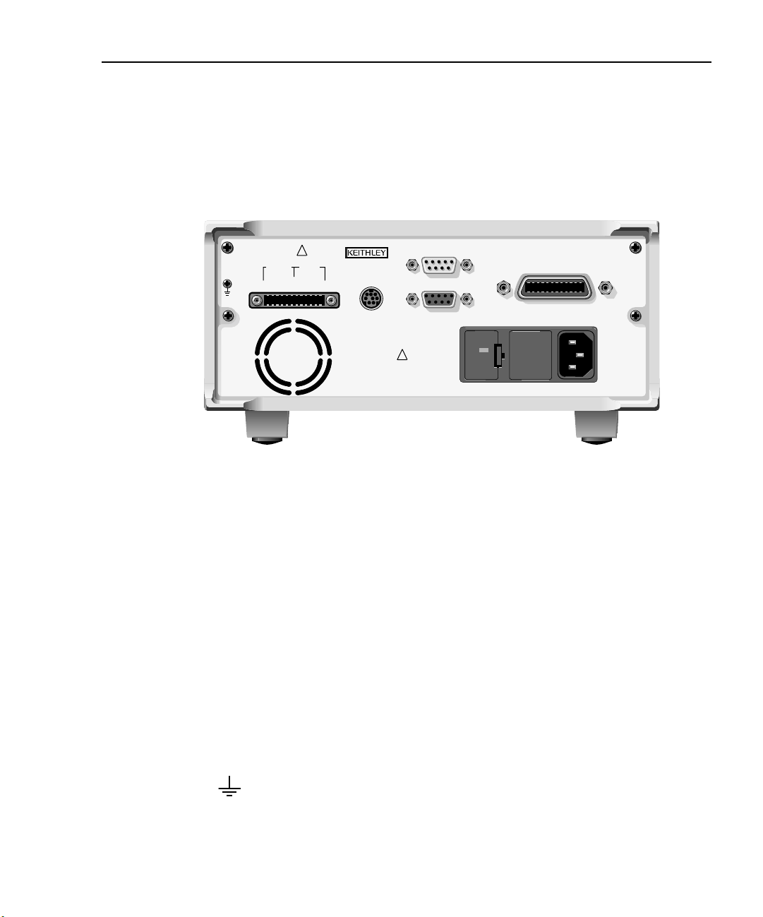
Rear panel summary
The rear panel of the Model 2510 is shown in Figure 1-2. The following abbreviated information should be reviewed before operating the instrument.
Figure 1-2
Model 2510 rear panel
CAT I
!
OUTPUT INPUT
F+ S+ S- F- F+ F- S+ S-
ISOLATION FROM EARTH: 30V MAX.
MADE IN
U.S.A.
ENABLE-DIG I/O
IEEE-488
(ENTER IEEE ADDRESS
WITH FRONT PANEL MENU)
LINE FUSE
SLOWBLOW
2.5A, 250V
!
LINE RATING
100-240VAC
90VA MAX
RS-232
120
50, 60 HZ
TRIGGER
LINK
Input/output connector:
OUTPUT terminals Source output connections to thermoelectric cooler.
INPUT terminals Temperature sensor input connections.
Digital I/O port:
ENABLE — DIG I/O Male DB-9 connector for digital output lines and output enable.
Power module:
Contains the AC line receptacle and the power line fuse.
Trigger link connector:
TRIGGER LINK 8-pin micro-DIN connector for sending and receiving trigger pulses. (Not
currently implemented).
RS-232 connector:
RS-232 Connector for RS-232 remote operation. Use a straight through (not null
modem) DB-9 cable such as a Keithley Model 7009-5.
GPIB connector:
IEEE-488 INTERFACE Connector for GPIB remote operation. Use a shielded cable (Model 7007-1
or 7007-2).
Ground screw:
Allows easy access to chassis ground.
Fan:
Internal fan turns on when the internal temperature reaches 50°C. Keep ventilation slots free of obstructions to avoid overheating.
Page 27

1-8 Getting Started Models 2510 and 2510-AT User’s Manual
Power-up
Line power connection
The Model 2510 operates from a line voltage in the range of 100 to 240V at a frequency of
50 to 60Hz. Line voltage and line frequency are automatically sensed. Therefore, there are
no switches to set. Before connecting the unit to line power, check to be sure the operating
voltage in your area is compatible.
CAUTION
Perform the following steps to connect the Model 2510 to line power and turn it on:
1. Before plugging in the power cord, make sure the front panel POWER switch is in
the off (0) position.
2. Connect the female end of the supplied power cord to the AC receptacle on the rear
panel.
3. Connect the other end of the supplied power cord to a properly grounded AC outlet.
WARNING
4. Turn on the instrument by pressing the front panel power switch to the on (1)
position.
Operating the instrument on an incorrect line voltage may cause damage, possibly voiding the warranty.
The power cord supplied with the Model 2510 contains a separate
ground for use with grounded outlets. When proper connections are
made, instrument chassis is connected to power line ground through
the ground wire in the power cord. Failure to use a grounded outlet
may result in personal injury or death due to electric shock.
Power-up sequence
On power-up, the Model 2510 performs self-tests on its EPROM and RAM and momentarily lights all segments and annunciators. If a failure is detected, the instrument momentarily displays an error message, and the ERR annunciator turns on.
If the instrument passes the self-tests, the firmware revision levels are displayed. For
example:
REV A01 A02
where: A01 is the main board ROM revision.
A02 is the display board ROM revision.
Page 28

Models 2510 and 2510-AT User’s Manual Getting Started 1-9
Also displayed is the line frequency (50 or 60Hz). (If the wrong frequency is displayed, it
can be set manually as covered below). The communication interface status is briefly displayed. If the IEEE-488 bus is the presently selected interface, the identification message
will include the primary address. For example, if the primary address is 15 (factory
default), the “IEEE Addr=15” message is displayed. (The Model 2510 does not support a
secondary address.) If the RS-232 interface is selected, the “RS-232” message is
displayed.
After the power-up sequence, the instrument goes to its normal display state with the output off (ON/OFF OUTPUT indicator light off). With the output off, the “OFF” message is
displayed.
System identification
To obtain the serial number and revision information, use the MENU/GENERAL/
SERIAL # selection. The top line displays the serial number; the bottom line displays the
firmware revision and date of calibration. You can then press the key to display SCPI
revision level and main board revision levels. You can also use *IDN? via remote (see
Section 8).
Line frequency setting
The power line frequency and line frequency setting should be the same, or readings may
be noisy. You can manually set the line frequency from the front panel as follows.
Set the line frequency from the front panel as follows:
1. Press the MENU key to display MAIN MENU.
2. Using the right arrow key, select AD-CTRL then press ENTER to display A/D
CONTROLS.
3. Note that LINE-FREQUENCY is displayed, then press ENTER to display the
LINE FREQUENCY menu.
4. Place the cursor on 50Hz or 60Hz, and press ENTER.
5. Press EXIT to return to normal display.
Page 29

1-10 Getting Started Models 2510 and 2510-AT User’s Manual
Fuse replacement
A rear panel fuse protects the power line input of the Model 2510. If the line fuse needs to
be replaced, perform the following steps:
Display
Display format
WARNING
CAUTION For continued protection against fire or instrument damage, replace
1. The fuse is located in a drawer adjacent to the AC receptacle (Figure 1-2). At the
bottom of the fuse drawer is a small tab. At this location, use a small bladed screwdriver to pry the fuse drawer open.
2. Slide the fuse drawer out to gain access to the fuse. Note that the fuse drawer does
not pull all the way out of the input module.
3. Snap the fuse out of the drawer and replace it with the same type: 250V, 2.5A slow
blow, 5 × 20mm, Keithley part number FU-106-2.5.
4. Push the fuse drawer back into the input module.
The Model 2510 display is used primarily to program setpoint values and display measured readings. Annunciators, which are located along the top of the reading/message display, indicate various states of operation, as covered previously in “Front panel summary,”
page 1-5.
Disconnect the line cord and all test leads and cables from the instrument before replacing the line fuse.
the fuse only with the type and rating listed. If the instrument repeatedly blows fuses, locate and correct the cause of the problem before
replacing the fuse.
On power-up, the top (primary) display shows the function being controlled by the PID
loop when the output is on (with the output off, “OFF” is displayed). The bottom display is
used for setpoint values (on the left), and alternate reading information for the selected
function (on the right) that can be selected with the DISPLAY TOGGLE/LOCAL key.
Page 30

Models 2510 and 2510-AT User’s Manual Getting Started 1-11
Display readings
Display readings depend on the selected function as discussed below.
Temperature function readings
The temperature function displays measured and setpoint temperatures. You can use the
DISPLAY TOGGLE key to cycle among:
• Peltier (PEL) voltage
• Peltier current
• Peltier power
• Peltier resistance
• Sensor (RT) resistance
NOTE The terms “Peltier” and “thermoelectric cooler” (TEC) are used interchange-
ably throughout this manual.
Voltage function readings
The voltage function displays measured and setpoint TEC voltages. DISPLAY TOGGLE
key cycles among:
• Temperature (T)
• Peltier current
• Peltier power
• Peltier resistance
• Sensor resistance
Current function readings
The current function displays measured and setpoint TEC currents, and you can use the
DISPLAY TOGGLE key to cycle among:
• Temperature
• Peltier voltage
• Peltier power
• Peltier resistance
• Sensor resistance
Page 31

1-12 Getting Started Models 2510 and 2510-AT User’s Manual
Resistance function readings
The resistance function displays measured RTD and thermistor sensor resistances, as well
as setpoint resistances, and you can use the DISPLAY TOGGLE key to cycle among:
• Temperature
• Peltier voltage
• Peltier current
• Peltier power
• Peltier resistance
Reading format
Reading information on the top line of the front panel display can be displayed using
either engineering units or scientific notation in either fixed- or floating-point format. Use
the GENERAL/NUMBERS selection of the main MENU to select the display format, as
discussed under “Menus,” page 1-19.
Engineering units example: 1.23456µA
Scientific notation example: 1.23456e -6
See “FORMat subsystem,” page 10-19, for remote reading formats.
Page 32

Models 2510 and 2510-AT User’s Manual Getting Started 1-13
Display examples
Typical display examples are shown in Table 1-1.
Table 1-1
Display examples
Function Display toggle sequence*
Temperature +025.000°C
Setpoint: +025.000°C PEL:-00.072V
+025.000°C
Setpoint: +025.000°C PEL:-0.0030A
+025.000°C
Setpoint: +025.000°C PEL:+00.002W
+025.000°C
Setpoint: +025.000°C PEL:+002.40Ω
+025.000°C
Setpoint: +025.000°C RT:+000.04kΩ
Voltage +01.000V
Setpoint: +01.000V T:+030.630°C
+01.000V
Setpoint: +01.000V PEL:+0.3689A
+01.000V
Setpoint: +01.000V PEL:+00.368W
+01.000V
Setpoint: +01.000V PEL:+002.71Ω
+01.000V
Setpoint: +01.000V RT:+000.04kΩ
Current +00.500A
Setpoint: +00.500A T:+033.200°C
+00.500A
Setpoint: +00.500A PEL:+01.377V
+00.500A
Setpoint: +00.500A PEL:+00.689W
+00.500A
Setpoint: +00.500A PEL:+002.75Ω
+00.500A
Setpoint: +00.500A RT:+002.75kΩ
Page 33

1-14 Getting Started Models 2510 and 2510-AT User’s Manual
Table 1-1 (continued)
Display examples
Function Display toggle sequence*
Resistance +010.00kΩ
Setpoint: +010.000kΩ T:+033.200°C
+010.00kΩ
Setpoint: +010.000kΩ PEL:+01.377V
+010.00kΩ
Setpoint: +010.000kΩ PEL:+0.3689A
+010.00kΩ
Setpoint: +010.000kΩ PEL:+00.689W
+010.00kΩ
Setpoint: +010.000kΩ PEL:+002.75Ω
*Use DISPLAY TOGGLE key to cycle through displays for each function.
Display messages
Table 1-2 shows front panel messages that may be displayed during normal operation.
Table 1-2
Display messages
Display message Description
OFF
UNDER-TEMP
OVER-TEMP
ILIM
VLIM
UNDER-OHMS
OVER-OHMS
URR
ORR
OpenLead
ShrtLead
OUTPUT turned off.
Temperature below lower limit.
Temperature above upper limit.
Current limit exceeded.
Voltage limit exceeded.
Resistance below lower limit.
Resistance above upper limit.
Under resistance range (sensor).
Over resistance range (sensor).
Sensor lead open.
Sensor lead shorted.
Page 34

Models 2510 and 2510-AT User’s Manual Getting Started 1-15
ON/OFF indicator
The ON/OFF indicator shows when the source output is turned on. This indicator will
glow with different colors depending on the following conditions:
• Red = heating (+Peltier voltage)
• Green = cooling (-Peltier voltage)
• Red and green both on (yellow) = voltage overflow (not voltage limit).
EDIT keys
The EDIT keys allow you to program setpoint and other values, and scroll through menu
selections as follows:
• When programming setpoint or other values, use the and keys to increment
and decrement values; use the left and right arrow keys to select the cursor position. Pressing any one of these keys enters the setpoint editing mode for the
selected function.
• When scrolling through menu selections, use the and keys to choose specific
items.
See “Menus,” page 1-19, for more details.
Status and error messages
During Model 2510 operation and programming, you will encounter a number of front
panel messages. Status and error messages are displayed momentarily. See Appendix B
for a list of status and error messages and ways to fix common errors.
Front panel tests
Use the TEST/DISPLAY-TESTS selection of the main MENU to test various aspects of
the front panel. Test selections include:
• KEYS – Front panel keys are tested. Pressing a key displays a message that identifies that key. Pressing EXIT twice cancels this test.
• DISPLAY PATTERNS – Use this selection to turn on all display pixels and annunciators. Subsequent keypresses cycle through tests that turn off annunciators and
corner pixels of each digit, turn on the rows of the top-left display digit, and turn on
all annunciators and pixels of each digit in a sequential manner. Press EXIT to cancel this test.
• CHAR SET – This test displays special characters. Press EXIT to cancel the test.
See “Menus,” page 1-19, for more menu information.
Page 35

1-16 Getting Started Models 2510 and 2510-AT User’s Manual
Default settings
By using appropriate menu selections, you can save and recall various instrument setups,
define the power-on configuration, or restore factory defaults as outlined below.
Saving and restoring user setups
You can save and restore five of your own user setups as covered below. This feature provides a convenient way to save specific instrument configurations and then recall them as
needed. Note that you can also set up the Model 2510 to restore a specific user setup at
power-on (see “Power-on configuration,” page 1-16). See Section 8 for information on
using *SAV and *RCL to perform these operations by remote.
Saving setups
1. Select the various instrument operating modes you wish to save.
2. Press the MENU key, select SAVESETUP, then press ENTER.
3. Select SAVE, then press ENTER.
4. Select the setup position (0 to 4) to save, then press ENTER to complete the
process.
Restoring setups
1. Press the MENU key, select SAVESETUP, then press ENTER.
2. Select RESTORE, then press ENTER.
3. Select the setup position (0 to 4) to restore, then press ENTER to complete the
process.
Power-on configuration
You can also define which of the stored setups (factory default or user) the instrument
assumes as the power-on configuration as follows:
1. Press the MENU key, select SAVESETUP, then press ENTER.
2. Select POWERON, then press ENTER.
3. From the SET POWER-ON DEFAULT menu, choose the power-on configuration:
BENCH or GPIB (see below), or USER-SETUP-NUMBER.
4. If you chose to use a user setup as the power-on configuration, select the user setup
number, then press ENTER.
Factory default settings
There are two sets of factory defaults, BENCH (front panel) and GPIB (remote). For front
panel operation, BENCH and GPIB defaults are the same and are summarized in
Table 1-3. You can restore these default conditions as follows:
1. Press the MENU key, select SAVESETUP, then press ENTER.
2. Select RESET, then press ENTER.
3. Select BENCH or GPIB defaults, then press ENTER to complete the process.
See the SCPI reference tables in Section 10 for remote default information.
Page 36

Models 2510 and 2510-AT User’s Manual Getting Started 1-17
Table 1-3
Factory front panel default settings
Setting Front panel BENCH and GPIB default*
Control function Temperature
Temperature function
Setpoint 25°C (298.15K, 77°F)
Protection high limit 50°C (323.15K, 122°F)
Protection low limit 0°C (273.15K, 32°F)
Protection state Enabled
Temperature units Celsius
Sensor current 2.5mA (100Ω range, RTD)
833.3µA (1kΩ range)
100µA (10kΩ range)
33.3µA (100kΩ range)
Sensor auto current state On
Sensor type Thermistor
Sense mode 2-wire
RTD sensor parameters
Type PT385
Range 100Ω
Alpha (α) 0.00385
Beta (β) 0.111
Delta (δ) 1.507
Thermistor sensor parameters
Range 10kΩ
A 1.13030e-3
B 2.33894e-4
C 8.85983e-8
Solid-state sensor parameters
VSS gain 1e-2
VSS offset 0
ISS gain 1e-6
ISS offset 0
Proportional constant 20
Integral constant 0.6
Derivative constant 0
Voltage function
Setpoint 0V
Voltage protection limit 10.5V
Proportional constant 10
Integral constant 20
Derivative constant 0
* BENCH defaults are the same as :SYSTem:PRESet defaults (Section 10). GPIB defaults are the same
as *RST defaults (Section 8).
** Not affected by BENCH or GPIB RESET.
Page 37

1-18 Getting Started Models 2510 and 2510-AT User’s Manual
Table 1-3 (continued)
Factory front panel default settings
Setting Front panel BENCH and GPIB default*
Current function
Setpoint 0A
Current protection limit 2A
Proportional constant 10
Integral constant 20
Derivative constant 0
Resistance function
Setpoint 100Ω (100Ω RTD or thermistor)
1kΩ (1kΩ RTD or thermistor)
10kΩ (10kΩ thermistor)
100kΩ (100kΩ thermistor)
Protection high limit 200Ω (100Ω RTD or thermistor)
2kΩ (1kΩ RTD or thermistor)
20kΩ (10kΩ thermistor)
200kΩ (100kΩ thermistor)
Protection low limit 50Ω (100Ω RTD or thermistor)
500Ω (1kΩ RTD or thermistor)
5kΩ (10kΩ thermistor),
50kΩ (100kΩ thermistor)
Protection state Enabled
Sensor current 2.5mA (100Ω range )
833.3µA (1kΩ range)
100µA (10kΩ range)
33.3µA (100kΩ range)
Sensor current auto state On
Sensor type Thermistor
Sense mode 2-wire
Thermistor range 10kΩ
Proportional constant 20
Integral constant 0.6
Derivative constant 0
Output On/Off Off
Digital I/O enable line Off
Peltier (cooler) ground connect mode Disabled
Digital I/O port output value 15
Display format** Engineering units
Setpoint tolerance percentage 0.5%
Window size 5
** BENCH defaults are the same as :SYSTem:PRESet defaults (Section 10). GPIB defaults are the same
as *RST defaults (Section 8).
** Not affected by BENCH or GPIB RESET.
Page 38

Models 2510 and 2510-AT User’s Manual Getting Started 1-19
Menus
The following paragraphs discuss the main menu, function configuration menus, and rules
to navigate menus.
Main menu
Use the MENU key to access the Main Menu to select, configure, and/or perform various
instrument operations, as shown in Table 1-4 and in Figure 1-3. Use the “Rules to navigate
menus,” page 1-21, to check and/or change Main Menu options.
Table 1-4
Main menu
Menu item
1
Description Parameters
SAVESETUP
SAVE
RESTORE
POWERON
BENCH
GPIB
USER-SETUP-NUMBER
RESET
COMMUNICATION
GPIB
RS-232
BAUD
BITS
PARITY
TERMINATOR
FLOW-CTRL
Configure setup conditions.
Save present Model 2510 setup to memory location.
Return the Model 2510 to setup saved in memory.
Select the power-on default setup.
Powers-on to BENCH defaults.
Powers-on to GPIB defaults.
Powers-on to user setup.
2
Returns unit to BENCH or GPIB defaults.
Select and configure remote interface.
Select GPIB (IEEE-488 Bus), set primary address.
Select SCPI or 488.1 protocol (Appendix F).
Select the RS-232 interface, set parameters.
Select baud rate.
Select number of data bits.
Select parity.
Select terminator.
Select flow control.
0 to 4
0 to 4
0 to 4
0 to 30
(Default: 15)
57600, 38400,
19200, 9600,
4800, 2400,
1200, 600, 300
7 or 8
NONE, ODD,
EVEN
CR, CR+LF,
LF, or LF+CR
NONE or
XON/XOFF
Page 39

1-20 Getting Started Models 2510 and 2510-AT User’s Manual
Table 1-4 (continued)
Main menu
Menu item
3
CAL
UNLOCK
EXECUTE
VIEW DATES
SAVE
LOCK
CHANGE-PASSWORD
TEST
DISPLAY TESTS
KEYS
DISPLAY-PATTERNS
CHAR SET
A/D CTRL
LINE-FREQUENCY
GENERAL
DIGOUT
SERIAL#
TIMESTAMP
NUMBERS
1
Description Parameters
Calibrate Model 2510. (See Service Manual.)
Unlock calibration.
Execute calibration steps.
Display calibration dates and count.
Save calibration constants.
Lock out calibration.
Change calibration password.
Perform tests on Model 2510.
4
Test front panel keys and display digits.
Test front panel keys.
Test display pixels and annunciators.
Test display characters.
Select line frequency.
50 or 60Hz
Set the line frequency.
Select general operations.
Set Digital I/O port bit pattern.
0 to 15
Display serial number, firmware revision, SCPI version.
Reset timestamp.
Select engineering units or scientific notation display
format (top display line only). Select FLOATING
YES or NO
ENGR,
SCIENTIFIC
EXP or FIXED EXP for SCIENTIFIC.
NOTES
1
Top level menu choices indicated in bold. Indentation identifies each lower submenu level.
2
When the remote operation interface selection (GPIB or RS-232) is changed, the Model 2510 performs a power-on reset. To check or
change options of the selected interface, you must re-enter the menu structure.
3
Only VIEW DATES is accessible when calibration is locked. Password required to unlock calibration. See Service Manual.
4
Press EXIT key to cancel test.
Page 40

Models 2510 and 2510-AT User’s Manual Getting Started 1-21
Rules to navigate menus
Many functions and operations are configured from the front panel menus. Use the following rules to navigate through these configuration menus:
• A menu item is selected by placing the cursor on it and pressing ENTER. Cursor
position is denoted by the blinking menu item or option. The EDIT left and right
arrow keys control cursor position.
• A displayed arrow on the bottom line indicates there are one or more additional
items (or messages) to select from. Use the appropriate EDIT cursor key to display
them.
• A numeric value is changed by placing the cursor on the digit to be changed and
using the EDIT and keys.
• A change is executed only when ENTER is pressed. Entering an invalid parameter
generates an error, and the entry is ignored. However, entering an out-of-range
value (too small or too large) selects the lower or upper limit, respectively.
• The EXIT key is used to back out of the menu structure. Any change that is not
entered is cancelled when EXIT is pressed.
Configuration menus
There are five configuration menus that can be accessed by pressing the CONFIG key followed by the appropriate key (T, V, I, R, OUTPUT, or EDIT). Configuration menus on the
following pages are available for these operating functions:
• Temperature (CONFIG T): Table 1-5.
• Voltage source (CONFIG V): Table 1-6.
• Current source (CONFIG I): Table 1-7.
• Resistance (CONFIG R): Table 1-8.
• Output (CONFIG OUTPUT): Table 1-9.
• Setpoint tolerance (CONFIG EDIT): Table 1-10.
NOTE See “Configuring functions,” page 3-3, for parameter information.
Page 41

1-22 Getting Started Models 2510 and 2510-AT User’s Manual
Figure 1-3
Main menu tree
Press MENU key (Use and to select item, then press ENTER).
SAVESETUP
SAVE
RESTORE
POWERON
BENCH
GPIB
USER-SETUP-NUMBER
RESET
COMMUNICATION
GPIB
RS-232
BAUD
BITS
PARITY
TERMINATOR
FLOW-CTRL
CAL
UNLOCK
EXECUTE
VIEW-DATES
SAVE
LOCK
CHANGE-PASSWORD
TEST
DISPLAY-TESTS
KEYS
DISPLAY-PATTERNS
CHAR-SET
A/D CTRL
LINE-FREQ
50Hz
GENERAL
DIGOUT
SERIAL#
TIMESTAMP
NUMBERS
▲
60Hz
▲
Page 42

Models 2510 and 2510-AT User’s Manual Getting Started 1-23
Table 1-5
Temperature configuration menu
Configuration menu item Description
PROTECTION
CONTROL
LOLIM
HILIM
SENSOR-TYPE
THERMISTOR
RANGE
A
B
C
I-SRC
SENSE-MODE
RTD
TYPE
RANGE
I-SRC
SENSE-MODE
I-SS
OFFSET
SCALE-FACTOR
V-SS
OFFSET
SCALE-FACTOR
Configure temperature protection.
ENABLE or DISABLE temperature protection.
Program lower temperature limit.
Program higher temperature limit.
Select sensor type and settings.
Program thermistor settings.
Set thermistor range (100Ω, 1kΩ, 10kΩ, 100kΩ).
Program A coefficient.
Program B coefficient.
Program C coefficient.
Set thermistor current (AUTO, 3.3µA, 10µA, 33.3µA, 100µA, 833.3µA,
2.5mA).
Select 2-WIRE or 4-WIRE sense mode.
Program RTD sensor parameters.
Select PT385, PT3916, PT100, D100, F100, USER type. Program USER α,
β, δ.
Set RTD range (100Ω or 1000Ω).
Set RTD current (AUTO, 3.3µA, 10µA, 33.3µA, 100µA, 833.3µA, 2.5mA).
Select 2-WIRE or 4-WIRE sense mode.
Program current solid-state sensor settings.
Program offset (K).
Program slope (K/A).
Program voltage solid-state sensor settings.
Program offset (K).
Program slope (K/A).
UNITS Select temperature units (°C, Kelvin, °F).
PID
PROPORTIONAL
INTEGRAL
DERIVATIVE
Program PID loop constants for temperature control.
Set proportional constant.
Set integral constant.
Set derivative constant.
Page 43

1-24 Getting Started Models 2510 and 2510-AT User’s Manual
Table 1-6
Voltage source configuration menu
Configuration menu item Description
PROTECTION Set voltage protection limit.
PID
PROPORTIONAL
INTEGRAL
DERIVATIVE
Program PID loop constants for voltage control.
Set proportional constant.
Set integral constant.
Set derivative constant.
Table 1-7
Current source configuration menu
Configuration menu item Description
PROTECTION Set current protection limit.
PID
PROPORTIONAL
INTEGRAL
DERIVATIVE
Program PID loop constants for current control.
Set proportional constant.
Set integral constant.
Set derivative constant.
Page 44

Models 2510 and 2510-AT User’s Manual Getting Started 1-25
Table 1-8
Resistance configuration menu
Configuration menu item Description
FUNCTION Select DC resistance function.
AC-OHMS Select AC resistance function.
TEMP-CONTROL
PROTECTION
CONTROL
LOLIM
HILIM
SENSOR-TYPE
THERMISTOR
RANGE
I-SRC
SENSE-MODE
RTD
I-SRC
RANGE
SENSE-MODE
PID
PROPORTIONAL
INTEGRAL
DERIVATIVE
Program DC resistance parameters.
Configure resistance protection.
ENABLE or DISABLE resistance protection.
Program lower resistance limit.
Program higher resistance limit.
Select sensor type and settings.
Program thermistor settings.
Set thermistor range (100Ω, 1kΩ, 10kΩ, 100kΩ).
Set thermistor current (AUTO, 3.3µA, 10µA, 33.3µA, 100µA, 833.3µA,
2.5mA).
Select 2-WIRE or 4-WIRE sense mode.
Program RTD settings.
Set RTD current (AUTO, 3.3µA, 10µA, 33.3µA, 100µA, 833.3µA, 2.5mA).
Set RTD range (100Ω or 1000Ω).
Select 2-WIRE or 4-WIRE sense mode.
Program PID loop constants for resistance.
Set proportional constant.
Set integral constant.
Set derivative constant.
Page 45

1-26 Getting Started Models 2510 and 2510-AT User’s Manual
Table 1-9
Output configuration menu
Configuration menu item Description
GND-CONNECT
DISABLE
ENABLE
ENABLE
DISABLE
ENABLE
Select input/output analog common (ground) connection.
Disable ground connection.
Enable ground connection.
Enable/disable Digital I/O port output enable line.
Inactivate output enable line.
Activate output enable line.
Table 1-10
Setpoint tolerance configuration menu
Configuration menu item Description
SETPOINT-TOLERANCE
PERCENTAGE
WINDOW-SIZE
Percent of range for setpoint tolerance.
Number readings to be within tolerance.
Page 46

2
Connections
• Input/output connections — Discusses connections for the thermoelectric cooler
and temperature sensor.
• Sense selection — Summarizes 2-wire and 4-wire sensing selection for both
INPUT and OUTPUT terminals.
• Ground connect mode — Describes using the ground connect mode.
Page 47

2-2 Connections Models 2510 and 2510-AT User’s Manual
WARNING:NO INTERNAL OPERATOR SERVICABLE PARTS,SERVICE BY QUALIFIED PERSONNEL ONLY.
WARNING:NO INTERNAL OPERATOR SERVICABLE PARTS,SERVICE BY QUALIFIED PERSONNEL ONLY.
CAUTION:FOR CONTINUED PROTECTION AGAINST FIRE HAZARD,REPLACE FUSE WITH SAME TYPE AND RATING.
CAUTION:FOR CONTINUED PROTECTION AGAINST FIRE HAZARD,REPLACE FUSE WITH SAME TYPE AND RATING.
Input/output connections
Input/output connector
The input/output connector is located on the rear panel (see Figure 2-1 and Figure 2-2).
Terminals include:
• OUTPUT terminals: F+, F- (force), S+, and S- (sense) connections to thermoelectric cooler.
• INPUT terminals: F+, F- (force), S+, and S- (Kelvin sense) connections to temperature sensor.
Use the supplied mating connector for connections (Keithley part number CS-846).
NOTE The Model 2510 assumes that a positive output current is a heating current.
2-wire connections
Figure 2-1 shows basic 2-wire signal connections. Note that the OUTPUT F (force) termi-
nals are connected to the thermoelectric cooler (TEC), while the INPUT F terminals are
connected to the temperature sensor. 2-wire sensor connections are recommended for:
• Thermistor and RTD sensors with ≥1kΩ resistance.
• Both AD590 current and LM335 voltage type solid-state sensors.
Figure 2-1
2-wire input/output connections
RTD, Thermistor, or Solid-State
Temperature Sensor
RT = Thermistor or RTD sensor
LM335 = Voltage solid-state sensor
AD590 = Current solid-state sensor
Mating Connector
-
+
LM335 AD590
-
INPUT F -
R
T
+
INPUT F +
Note: These connections
assume positive
current heats TEC.
TEC
-
OUTPUT F -
+
OUTPUT F +
CAT I
!
OUTPUT INPUT
F+ S+ S- F- F+ F- S+ S-
ISOLATION FROM EARTH: 30V MAX.
F+ F- F+ F-
Output
Input
Model 2510
MADE IN
U.S.A.
ENABLE-DIG I/O
!
RS-232
LINE FUSE
SLOWBLOW
2.5A, 250V
LINE RATING
100-240VAC
50, 60 HZ
90VA MAX
TRIGGER
LINK
120
IEEE-488
(ENTER IEEE ADDRESS
WITH FRONT PANEL MENU)
Page 48

Models 2510 and 2510-AT User’s Manual Connections 2-3
WARNING:NO INTERNAL OPERATOR SERVICABLE PARTS,SERVICE BY QUALIFIED PERSONNEL ONLY.
WARNING:NO INTERNAL OPERATOR SERVICABLE PARTS,SERVICE BY QUALIFIED PERSONNEL ONLY.
CAUTION:FOR CONTINUED PROTECTION AGAINST FIRE HAZARD,REPLACE FUSE WITH SAME TYPE AND RATING.
CAUTION:FOR CONTINUED PROTECTION AGAINST FIRE HAZARD,REPLACE FUSE WITH SAME TYPE AND RATING.
4-wire connections
Figure 2-2 shows basic 4-wire signal connections. In this case, the OUTPUT F (force) and
S (Kelvin sense) terminals are connected to the thermoelectric cooler, while the INPUT F
and S terminals are connected to the temperature sensor. 4-wire sensor connections are
recommended for RTD and thermistor sensors with <1kΩ resistance. This type of connection will eliminate lead resistance errors. (See “Sensing considerations,” page 2-5.)
Figure 2-2
4-wire input/output connections
RTD or Thermistor
Temperature Sensor
S-
INPUT S -
R
T
-
-
S-
S+
+
TEC
Note: These connections
assume positive
current heats TEC.
S+
INPUT S +
INPUT F -
INPUT F ++
OUTPUT F -
OUTPUT S -
OUTPUT S +
OUTPUT F +
CAT I
!
OUTPUT INPUT
F+ S+ S- F- F+ F- S+ S-
ISOLATION FROM EARTH: 30V MAX.
Mating Connector
F+ S+ S- F- F+ F- S+ S-
Output
Model 2510
MADE IN
U.S.A.
ENABLE-DIG I/O
SLOWBLOW
!
LINE RATING
RS-232
LINE FUSE
2.5A, 250V
100-240VAC
50, 60 HZ
90VA MAX
TRIGGER
LINK
Input
120
IEEE-488
(ENTER IEEE ADDRESS
WITH FRONT PANEL MENU)
Page 49

2-4 Connections Models 2510 and 2510-AT User’s Manual
Reversing TEC connections
The Model 2510 assumes that a positive TEC current is a heating current. To configure
your system so that a positive current is a cooling current, reverse your TEC connections
as shown in Figure 2-3. In this case OUTPUT F- and S- are connected to TEC+, while output F+ and S+ are connected to TEC-.
Figure 2-3
TEC connections for positive current, cooling operation
Model 2510 or 2510-AT
OUTPUT INPUT
S+ S- F- F+ S+ S-F-
F+
TEC-
Peltier
(TEC)
TEC+
Thermistor
DUT
Page 50

Models 2510 and 2510-AT User’s Manual Connections 2-5
R
T
V
M
I
--------=
Sense selection
4-wire connections minimize the detrimental effects of lead resistance by sourcing the test
current through one set of wires (OUTPUT and INPUT F terminals) and measuring the
voltage across the device through a second set of wires (S terminals).
OUTPUT sensing
Sensing though the OUTPUT terminals is automatic with no user programming required.
To use sensing with OUTPUT connections, simply make 4-wire connections to the thermoelectric cooler as shown in Figure 2-2. Note that it is recommended that you use 4-wire
OUTPUT connections whenever the thermoelectric cooler voltage or resistance must be
accurately known.
INPUT sensing
4-wire sensing may be used for both RTD and thermistor sensors, but sense selection is
not automatic. The sense mode must be manually set when choosing a sensor type with the
CONFIG T or CONFIG R menus. See “Configuring functions,” page 3-3, for details.
NOTE 4-wire connections and 4-wire sensing should be used with RTD and thermistor
sensors with resistances <1kΩ to avoid errors caused by lead resistance.
Sensing considerations
Figure 2-4 shows a comparison of 2- and 4-wire sensing methods. In these examples, the
INPUT terminals are connected to a thermistor type temperature sensor, but the considerations for RTD sensors and OUTPUT connections to the TEC are similar.
2-wire sensing
The 2-wire connecting method is shown in Figure 2-4A. To determine the sensor resistance, the test current (I) is forced through the F+ and F- test leads and the resistance of the
thermistor being measured (RT). The Model 2510 then measures the voltage across the
thermistor through the same F+ and F- connecting wires and computes the thermistor
resistance from the measured voltage (VM) and the current as follows:
The main problem with 2-wire connections is the wire resistance (R
rent (I) causes a small but significant voltage drop across the wire resistances, the measured voltage (VM) will not be exactly the same as the voltage (VT) directly across the
thermistor, and considerable resistance and temperature measurement error can result.
). Since the test cur-
W
Page 51

2-6 Connections Models 2510 and 2510-AT User’s Manual
Figure 2-4
Sensing methods
Model 2510
I
M
V
A. 2-Wire Connections
Model 2510
I
M
V
F+
INPUT
F-
F+
S+
INPUT
S-
F-
Rw
Rw
Rw
Rw
Rw
Rw
T
V
T
V
Thermistor
Thermistor
T
R
T
R
B. 4-Wire Connections
4-wire sensing
Due to the limitations of the 2-wire method, the 4-wire connection method shown in
Figure 2-4B is recommended for sensors <1kΩ. With this configuration, the test current (I)
is forced through the thermistor through the F+ and F- wires, while the voltage across the
thermistor is measured through a second set of wires connected to the S+ and S- (sense)
terminals. Although some small current may flow through the sense wires, it is usually
negligible and can generally be ignored for all practical purposes. Since the voltage drop
across the sense wires is negligible, the voltage measured by the Model 2510 is essentially
the same as the voltage across the thermistor (VM ≅ VT), and more accurate resistance and
temperature measurements result from the following resistance calculation:
V
T
-------=
R
T
I
Page 52

Models 2510 and 2510-AT User’s Manual Connections 2-7
Ground connect mode
Ground connect connects output low to sensor measurement ground, as shown in
Figure 2-5. Without ground connect, the output can float up to ±10V from sensor measure-
ment ground.
Figure 2-5
Ground connect mode
Rectifier
AC
AC ohms measurement
The AC ohms measurement can be used to determine the AC resistance across the OUTPUT F+ and F- terminals. This measurement is typically used as a pre-test of Peltier static
resistance before using PID control. The AC ohms measurement can be displayed from the
front panel by configuring the resistance function (Section 3) and via remote by using the
:MEAS:RES:AC? query (Section 9).
As shown in Figure 2-6, the AC ohms command results in a 9.6mA current being pulsed
through the DUT in opposite directions so as to eliminate system voltage offset and minimize temperature change of the Peltier. During thermoelectric (PID) control, dynamic
(DC) resistance can be displayed on the front panel display by pressing the DISPLAY
TOGGLE key or via remote with the :MEAS:RES:DC? query (Section 9).
Figure 2-6
AC ohms measurement
TEC
GND Connect
Measurement
Circuit
F-
S-
S+
F+
Output
DUT
9.6mA
Page 53

3
Basic Operation
• Safety precautions — Lists safety precautions that should be observed when using
the unit.
• Operation overview — Summarizes the basic operating characteristics of the
Model 2510.
• Configuring functions — Provides step-by-step procedures for configuring the
Model 2510 temperature, voltage, current, and resistance functions.
• Adjusting setpoints — Provides basic information on adjusting setpoints and
allowable setpoint ranges.
• Basic front panel control-measure procedure — Describes the basic procedure
for setting up unit control and measurement operating modes and using the unit
from the front panel.
• Basic remote control-measure procedure — Describes the basic procedure for
setting up unit control and measurement operating modes and using the unit using
remote commands.
• Protection limits — Discusses the protection limits for the various functions.
• Setpoint tolerances — Details using the setpoint tolerance to determine when the
control setting is within the desired setpoint window.
• Temperature sensors — Covers various aspects of temperature sensors.
Page 54

3-2 Basic Operation Models 2510 and 2510-AT User’s Manual
Safety precautions
WARNING The device under test may be at temperature extremes. Improper use
of the temperature controller may cause personal injury. Allow sufficient time for the device under test to return to a safe temperature after
testing before making personal contact. Use a heat sink or physical
barriers as necessary to avoid contact.
WARNING The maximum common-mode voltage is 30V DC. Exceeding this value
will result in a shock hazard because of the floating source.
CAUTION The maximum voltage between the INPUT/OUTPUT S (sense) termi-
nals is 1V. (Difference between force and sense lines for both INPUT
and OUTPUT terminals.) Exceeding this value may result in instrument damage.
Operation overview
Control characteristics
The Model 2510 has the following basic control characteristics:
• Control capabilities — Control thermoelectric cooler (TEC) power to maintain
constant temperature, current, voltage, or thermistor resistance.
• Output range — ±10V DC at up to ±5A DC.
• Setpoint range — -50°C to 225°C.
• Setpoint resolution — ±0.001°C.
• Over temperature limit — 250°C maximum.
• Under temperature limit — -50°C minimum.
• Current limit — 1A to 5.25A.
Measurement characteristics
Basic Model 2510 measurement characteristics include:
• Measurement functions — (AC resistance available only via remote.) DC resistance; operating voltage, current, and power; and AC resistance.
• Thermal feedback element types — PT385, PT3916, PT100, D10, F100 RTD
(100Ω or 1000Ω); 100Ω, 1kΩ, 10kΩ, and 100kΩ thermistor; AD590 (current) and
LM335 (voltage) solid-state temperature sensors.
Page 55

Models 2510 and 2510-AT User’s Manual Basic Operation 3-3
Limit characteristics
For each control function (T, V, I, and R), you can program limits to protect the DUT for
damage or even to perform limit testing. The Model 2510 will display an appropriate status
message if a programmed limit has been exceeded, and you can query if a limit has been
tripped with an appropriate remote command (see Section 10). See “Configuring func-
tions,” page 3-3, for details on programming protection limits for the various functions.
Configuring functions
The following paragraphs list step-by-step procedures for configuring the temperature,
voltage, current, and resistance functions.
NOTE See “PID Control Concepts,” page 4-1, for information on setting PID control
loop proportional, integral, and derivative constants. See also “Sensor coeffi-
cients,” page 4-14, for information on thermistor and RTD coefficients.
Configuring temperature
Using Table 3-1 as a guide, configure the temperature function as follows:
1. Press CONFIG then T to access the temperature configuration menu.
2. Select PROTECTION, then press ENTER.
3. Select CONTROL, then press ENTER.
4. Choose ENABLE, then press ENTER.
5. Select LOLIM, then press ENTER. Set the low temperature limit using the EDIT
keys, then press ENTER again.
6. Choose HILIM, then press ENTER, set the high temperature limit using the EDIT
keys, then again press ENTER.
7. Press EXIT, choose SENSOR-TYPE, then press ENTER.
8. Choose the desired temperature sensor (THERMISTOR, RTD, I-SS, or V-SS), then
press ENTER.
9. Program the settings for the selected temperature sensor. For example, for an RTD
sensor, choose the following:
• TYPE: Select PT385, PT3916, PT100, D100, F100, or USER type. (For
USER type, set α, β, and δ.)
• RANGE: Select 100 or 1000.
• I-SRC: Set RTD current (AUTO, 3.3µA, 10µA, 33.3µA, 100µA, 833.3µA, or
2.5mA).
• SENSE-MODE: Choose 2-WIRE or 4-WIRE sensing. (Use 4-wire for sensors
<1kΩ).
10. Press EXIT as needed to return to the CONFIG TEMPERATURE menu.
11. Select UNITS, press ENTER, then select the desired units (°C, °F, or Kelvin).
Page 56

3-4 Basic Operation Models 2510 and 2510-AT User’s Manual
12. Choose PID, then press ENTER.
13. Program your PROPORTIONAL, INTEGRAL, and DERIVATIVE constants as
required.
14. After programming, press EXIT as necessary to return to normal display.
Table 3-1
Temperature configuration menu
Configuration
menu item Description
PROTECTION
CONTROL
LOLIM
HILIM
SENSOR-TYPE
THERMISTOR
RANGE
A
B
C
I-SRC
SENSE-MODE
RTD
TYPE
α
β
δ
RANGE
I-SRC
SENSE-MODE
ISS
OFFSET
SCALE-FACTOR
VSS
OFFSET
SCALE-FACTOR
Configure temperature protection.
ENABLE or DISABLE temperature protection.
Program lower limit (-50 to +250°C; 223.15 to 523.15K; -58 to +482°F).*
Program higher limit (-50 to +250°C; 223.15 to 523.15K; -58 to +482°F).*
Select sensor type and settings.
Program thermistor settings.
Set thermistor range (100Ω, 1kΩ, 10kΩ, 100kΩ).
Program A coefficient (-10 to +10).
Program B coefficient (-10 to +10).
Program C coefficient (-10 to +10).
Set thermistor current (AUTO, 3.3µA, 10µA, 33.3µA, 100µA, 833.3µA, 2.5mA).
Select 2-WIRE or 4-WIRE sense mode.
Program RTD sensor parameters.
Select PT385, PT3916, PT100, D100, F100, USER type. Program USER α, β, δ.
Program USER alpha (0 to 0.01).
Program USER beta (0 to 1).
Program USER delta (0 to 5).
Set RTD range (100Ω or 1000Ω).
Set RTD current (AUTO, 3.3µA, 10µA, 33.3µA, 100µA, 833.3µA, 2.5mA).
Select 2-WIRE or 4-WIRE sense mode.
Program current solid-state sensor settings.
Program offset (K), -999.999 to 999.999
Program slope (K/A), 0 to 9.999e-4
Program voltage solid-state sensor settings.
Program offset (K), -999.999 to 999.999
Program slope (K/A), 0 to 9.999e-2
UNITS
PID
PROPORTIONAL
INTEGRAL
DERIVATIVE
*Lower limit cannot be set higher than higher limit. Higher limit cannot be set lower than lower limit.
Select temperature units (°C, Kelvin, °F).
Program PID loop constants for temperature.
Set proportional constant (0 to 100000).
Set integral constant (0 to 100000).
Set derivative constant (0 to 100000).
Page 57

Models 2510 and 2510-AT User’s Manual Basic Operation 3-5
Configuring voltage
Using Table 3-2 as a guide, configure the voltage source as follows:
1. Press CONFIG then V to access the voltage configuration menu.
2. Select PROTECTION, then press ENTER.
3. Using the EDIT keys, set the voltage limit to the desired value, then press ENTER.
4. Choose PID, then press ENTER.
5. Program the PROPORTIONAL, INTEGRAL, and DERIVATIVE constants as
required.
6. After programming, press EXIT as necessary to return to normal display.
Table 3-2
Voltage source configuration menu
Configuration menu item Description
PROTECTION Set voltage protection limit (0.5 to +10.5V).
PID
PROPORTIONAL
INTEGRAL
DERIVATIVE
Configuring current
Using Table 3-3 as a guide, configure the current source as follows:
1. Press CONFIG then I to enter the current configuration menu.
2. Select PROTECTION, then press ENTER.
3. Using the EDIT keys, set the current limit to the desired value, then press ENTER.
4. Choose PID, then press ENTER.
5. Program the PROPORTIONAL, INTEGRAL, and DERIVATIVE constants as
required.
6. Press EXIT to return to normal display.
Table 3-3
Current source configuration menu
Configuration menu item Description
PROTECTION Set current protection limit (1.00 to 5.25A).
PID
PROPORTIONAL
INTEGRAL
DERIVATIVE
Program PID loop constants for voltage.
Set proportional constant (0 to 100000).
Set integral constant (0 to 100000).
Set derivative constant (0 to 100000).
Program PID loop constants for current.
Set proportional constant (0 to 100000).
Set integral constant (0 to 100000).
Set derivative constant (0 to 100000).
Page 58

3-6 Basic Operation Models 2510 and 2510-AT User’s Manual
Configuring DC resistance
Using Table 3-4 as a guide, configure the resistance function as follows:
1. Press CONFIG then R to access the resistance configuration menu.
2. Select TEMP-CONTROL, then press ENTER.
3. Select PROTECTION, then press ENTER.
4. Select CONTROL, then press ENTER.
5. Select ENABLE, then press ENTER.
6. Select LOLIM, then press ENTER. Set the low resistance limit to the desired value,
then press ENTER.
7. Select HILIM, then press ENTER. Set the high resistance limit to the desired
value, then press ENTER.
8. Press EXIT to return to the CONFIG RESISTANCE menu.
9. Select SENSOR-TYPE, then press ENTER.
10. Choose either THERMISTOR or RTD sensor type, then press ENTER.
11. Program the settings for the selected temperature sensor. For example, for an RTD
sensor, choose the following:
• TYPE: Select PT385, PT3916, PT100, D100, F100, or USER type. (For
USER type, set α, β, and δ.)
• RANGE: Select 100 or 1000.
• I-SRC: Set RTD current (AUTO, 3.3µA, 10µA, 33.3µA, 100µA, 833.3µA, or
2.5mA).
• SENSE-MODE: Choose 2-WIRE or 4-WIRE sensing. (Use 4-wire for sensors
<1kΩ).
12. From the CONFIG RESISTANCE menu, choose PID, then press ENTER.
13. Program the PROPORTIONAL, INTEGRAL, and DERIVATIVE constants as
required.
14. After programming, press EXIT as necessary to return to normal display.
Configuring AC resistance
1. Press CONFIG then R to access the resistance configuration menu.
2. Select AC-OHMS, then press ENTER.
3. The output will turn off (if enabled), and the Model 2510 will then display the AC
resistance of the TEC whenever the resistance function is enabled by pressing the
R function button.
4. To return to DC resistance operation when the resistance function is enabled, enter
the resistance configuration menu, select FUNCTION, then press ENTER.
(To configure DC resistance, select TEMP-CONTROL, then program parameters
as usual.)
NOTE See “AC ohms measurement,” page 2-7, for more information.
Page 59

Models 2510 and 2510-AT User’s Manual Basic Operation 3-7
Table 3-4
Resistance configuration menu
Configuration menu
item Description
FUNCTION Select DC resistance function.
AC-OHMS Select AC resistance function.
TEMP-CONTROL
PROTECTION
CONTROL
LOLIM
Program DC resistance parameters.
Configure resistance protection.
ENABLE or DISABLE resistance protection.
Program lower resistance limit:
1Ω to 200Ω (100Ω RTD or thermistor)
5Ω to 2kΩ (1kΩ RTD or thermistor)
50Ω to 20kΩ (10kΩ thermistor)
500Ω to 200kΩ (100kΩ thermistor)
HILIM
Program higher resistance limit:
50Ω to 1kΩ (100Ω thermistor)
500Ω to 9.999kΩ (1kΩ thermistor)
5kΩ to 80kΩ (10kΩ thermistor)
50kΩ to 200kΩ (100kΩ thermistor)
50Ω to 250Ω (100Ω RTD)
500Ω to 3kΩ (1kΩ RTD)
SENSOR-TYPE
THERMISTOR
RANGE
I-SRC
Select sensor type and settings.
Program thermistor settings.
Set thermistor range (100Ω, 1kΩ, 10kΩ, 100kΩ).
Set thermistor current (AUTO, 3.3µA, 10µA, 33.3µA, 100µA, 833.3µA,
2.5mA).
SENSE-MODE
RTD
I-SRC
RANGE
SENSE-MODE
PID
PROPORTIONAL
INTEGRAL
DERIVATIVE
Select 2-WIRE or 4-WIRE sense mode.
Program RTD settings.
Set RTD current (AUTO, 3.3µA, 10µA, 33.3µA, 100µA, 833.3µA, 2.5mA).
Set RTD range (100Ω or 1000Ω).
Select 2-WIRE or 4-WIRE sense mode.
Program PID loop constants for resistance.
Set proportional constant (0 to 100000).
Set integral constant (0 to 100000).
Set derivative constant (0 to 100000).
Page 60

3-8 Basic Operation Models 2510 and 2510-AT User’s Manual
Configuring output
Using Table 3-5 as a guide, configure the output as follows:
1. Press CONFIG then OUTPUT to enter the output configuration menu.
2. Choose GND-CONNECT, then press ENTER.
3. ENABLE or DISABLE ground connect as required, then press ENTER.
4. If you are using the output enable circuit (see Section 5), select ENABLE, then
press ENTER. Select ENABLE from the OUTPUT ENABLE menu, then press
ENTER again.
5. Press EXIT to return to normal display.
Table 3-5
Output configuration menu
Configuration menu item* Description
GND-CONNECT
DISABLE
ENABLE
ENABLE
DISABLE
ENABLE
*See Section 2 for information on reversal and ground connect modes.
*See “Output enable line,” page 5-6, for output enable information.
Select input/output analog common (ground) connection.
Disable ground connection.
Enable ground connection.
Enable/disable Digital I/O port output enable line.
Inactivate output enable line.
Activate output enable line.
Configuring setpoint tolerance
Using Table 3-6 as a guide, follow the steps below to configure setpoint tolerance. See
“Setpoint tolerance,” page 3-15, for more details.
1. Press CONFIG, then any one of the four EDIT keys to access the setpoint tolerance
menu.
2. From the SETPOINT TOLERANCE MENU, select PERCENTAGE, then press
ENTER.
3. Choose PERCENTAGE, then press ENTER.
4. Using the EDIT keys, set the percentage to the desired value, then press ENTER.
5. Choose WINDOW-SIZE, then press ENTER.
6. Use the EDIT keys to set the number of readings to be within the tolerance window, then press ENTER.
7. Press EXIT to return to normal display.
Page 61

Models 2510 and 2510-AT User’s Manual Basic Operation 3-9
Table 3-6
Setpoint tolerance configuration menu
Configuration menu item Description
SETPOINT TOLERANCE
PERCENTAGE
WINDOW-SIZE
Percent of range for setpoint tolerance (0-100%), default 0.5%.
Number readings to be within tolerance (1-100), default 5.
Adjusting setpoints
To adjust a setpoint for a particular control function, simply press the function key for the
particular function (T, V, I, or R), then press one of the EDIT keys to enter the setpoint
adjustment mode. Use the EDIT keys to adjust the setpoint as follows:
• Use the left and right arrow keys to place the cursor on the digit to be changed.
• Use the and keys to increase or decrease the setpoint value.
Table 3-7 summarizes setpoint adjustment ranges for the four control functions.
NOTE You cannot adjust the setpoint above the upper protection (limit) setting (all
functions) or below the lower protection setting (temperature and resistance).
Table 3-7
Setpoint adjustment ranges
Function Adjustment range
Temperature (T)*
(Constant Peltier temperature)
Voltage (V)**
(Constant Peltier voltage)
Current (I)**
(Constant Peltier current)
Resistance (R)*
(Constant thermistor resistance)
*Setpoint cannot be set above or below protection limits.
**Setpoint cannot be set above protection limit.
-50 to +225°C
223.15 to 498.15K
-58 to 437°F
-10 to +10V
-5 to +5A
1Ω to 1kΩ (100Ω thermistor)
5Ω to 9.999kΩ (1kΩ thermistor)
50Ω to 80kΩ (10kΩ thermistor)
500Ω to 200kΩ (100kΩ thermistor)
1Ω to 250Ω (100Ω RTD)
5Ω to 3kΩ (1kΩ RTD)
Page 62

3-10 Basic Operation Models 2510 and 2510-AT User’s Manual
Basic front panel control-measure procedure
Use the following procedure to perform the basic control-measure operations.
NOTE The following procedure assumes that the Model 2510 is already connected to
the thermoelectric cooler and temperature sensor as explained in “Input/output
connections,” page 2-2.
Step 1: Select function.
Press the T,V, I, or R key to select the desired control function:
• T: Temperature function
• V: Voltage function
• I: Current function
• R: Resistance function
Step 2: Configure function.
Press CONFIG then the function key to configure the various operating parameter for the
function to be used. For example, to configure the temperature function, press CONFIG
then T, and then set the following operating parameters:
• PROTECTION: Enable protection, and program the high and low temperature
limits.
• SENSOR-TYPE: Select the type of sensor being used, then set the associated sensor parameters.
• UNITS: Select the desired temperature units.
• PID: Program the proportional, derivative, and integral loop constants.
NOTE See “Configuring functions,” page 3-3, and “Rules to navigate menus,”
page 1-21, for details on various menu selections and setting parameter values.
See PID Control Concepts and “Sensor coefficients,” page 4-14, for details on
programming the proportional, integral, and derivative constants and sensor
parameters.
Step 3: Adjust setpoint.
Press one of the EDIT keys to enter the setpoint editing mode for the selected function.
Use the and keys to increment and decrement setpoint values; use the left and right
arrow keys to select the cursor position.
Step 4: Set current limit.
If required, set the current limit as needed. (Press CONFIG then I, then use the
PROTECTION selection.)
Page 63

Models 2510 and 2510-AT User’s Manual Basic Operation 3-11
Step 5: Turn output on.
Turn the output on by pressing the ON/OFF OUTPUT key. The OUTPUT indicator will
turn on to indicate the output is on.
Step 6: Observe the display.
During operation, you can observe the front panel display for operating and measured
parameters. For example, for the temperature function, the display will show the measured
temperature and the temperature setpoint, and you can use the DISPLAY TOGGLE key to
cycle through the TEC voltage, current, power, and resistance values, as well as the sensor
resistance.
Step 7: Turn output off.
When finished, turn the output off by pressing the ON/OFF OUTPUT key. The OUTPUT
indicator light will turn off to show the output is off.
Basic remote control-measure procedure
Use the following procedure to perform the basic control-measure operations via remote.
See Section 10 for command details and Appendix E for an example program.
NOTE The following procedure assumes that the Model 2510 is already connected to
the thermoelectric cooler and temperature sensor as explained in “Input/output
connections,” page 2-2.
Step 1: Restore defaults.
Send the following command to restore defaults:
*RST
See Table 1-3 in Section 1.
Step 2: Select function.
Send the :SOUR:FUNC command to select the desired control function. For example, to
select the temperature function, send the following command:
:SOUR:FUNC TEMP
Page 64

3-12 Basic Operation Models 2510 and 2510-AT User’s Manual
Step 3: Configure selected function.
Send the commands to program temperature units, protection limits, sensor type, sensor
parameters, and PID loop constants. For example, the following commands configure the
temperature function:
:UNIT:TEMP CEL Celsius temperature limits
:SOUR:TEMP:PROT 100 Upper temperature limit = 100˚
:SOUR:TEMP:PROT:LOW 10 Lower temperature limit = 10˚
:TEMP:TRAN RTD Select RTD temperature sensor
:TEMP:RTD:TYPE PT100 Select PT100 RTD sensor
:TEMP:RTD:RANG 100 Set 100Ω range.
:TEMP:CURR:AUTO ON Use default RTD sensor current
:SYST:RSEN ON Enable 4-wire sensing
:SOUR:TEMP:LCON 10 Temperature gain constant = 10
:SOUR:TEMP:LCON:INT 0.5 Temperature integral constant = 0.5
:SOUR:TEMP:LCON:DER 0 Temperature derivative constant = 0
Step 4: Program setpoint.
Program the setpoint for the selected control function. For example, the following command programs the temperature setpoint to 50˚:
:SOUR:TEMP 50
Step 5: Set current limit.
If required, set the current limit with this command:
:SENS:CURR:PROT<Current_Limit>
Step 6: Turn output on.
Turn the output on to begin PID control by sending the following commands:
:OUTP ON
Step 7: Request readings.
During operation, you can request readings with the :FETCH? query. Note that bus reading elements are controlled with the :FORM:ELEM command. You can also request additional reading types with the following queries:
:MEAS:POW? Query thermoelectric cooler power
:MEAS:CURR? Query cooler current
:MEAS:TEMP? Query temperature
:MEAS:RES? Query cooler DC resistance
:MEAS:VOLT? Query cooler voltage
Page 65

Models 2510 and 2510-AT User’s Manual Basic Operation 3-13
Step 8: Turn output off.
When finished, turn the output off and halt PID control by sending:
:OUTP OFF
Protection limits
Protection limits for the four functions are discussed below. Table 3-8 summarizes protection limit characteristics.
NOTE For temperature and resistance, the upper limit cannot be set below the lower
limit and the lower limit cannot be set above the upper limit. Also, the setpoint
cannot exceed limit setting(s).
Table 3-8
Protection limit characteristics
Output
Function Limit range
Inhibited?* Display message
Temperature** Lower limit: -50 to +250°C
Upper limit: -50 to +250°C
Voltage 0.5 to 10.5V No VLIM
Current 1.0 to 5.25A No ILIM
Resistance** Lower limit:
1Ω to 200Ω (100Ω RTD or thermistor)
5Ω to 2kΩ (1kΩ RTD or thermistor)
50Ω to 20kΩ (10kΩ thermistor)
500Ω to 200kΩ (100kΩ thermistor)
Upper limit:
50Ω to 1kΩ (100Ω thermistor)
500Ω to 9.999kΩ (1kΩ thermistor)
5kΩ to 80kΩ (10kΩ thermistor)
50kΩ to 200kΩ (100kΩ thermistor)
50Ω to 250Ω (100Ω RTD)
500Ω to 3kΩ (1kΩ RTD)
* Yes indicates that output turns off if limit is exceeded and cannot be turned on when in limit.
**Lower limit cannot be set above upper limit. Upper limit cannot be set below lower limit.
Ye s
Ye s
Ye s
Ye s
UNDER-TEMP
OVER-TEMP
UNDER-OHMS
OVER-OHMS
Page 66

3-14 Basic Operation Models 2510 and 2510-AT User’s Manual
Temperature protection limits
The upper and lower temperature limits have a valid range of -50 to +250˚C. If the lower
limit is exceeded, “UNDER-TEMP” will be displayed on the front panel, and Bit 1 (UT)
of the Measurement Event Register will be set. If the upper limit is exceeded, “OVERTEMP” will be displayed on the front panel, and Bit 0 (OT) of the Measurement Event
Register will be set. You can program the unit to generate an SRQ if either limit is
exceeded (see Section 7). Note that OUTPUT ON/OFF is inhibited by exceeding either
limit. The output will turn off if either limit is exceeded, and you cannot turn on the output
with under- or over-limit conditions.
To program the temperature limits, press CONFIG then T, then select PROTECTION and
program the limits as required. See “Configuring temperature,” page 3-3, for details.
Voltage protection limit
The voltage limit has a valid range of 0.5 to 10.5V, and the default value is 10.5. If the
voltage limit is exceeded, “VLIM EXCEEDED” will be displayed on the front panel. Bit 2
(OV) of the Measurement Event Register will be set, and you can program the unit to generate an SRQ if the voltage limit is exceeded. Note that OUTPUT ON/OFF is not inhibited
by exceeding the voltage limit.
To program the voltage limit, press CONFIG then V, then select PROTECTION and program the limit as required. See “Configuring voltage,” page 3-5, for details.
Current protection limit
The current limit has a valid range of 1.0A to 5.25A, and the default value is 2.0. If the
current limit is exceeded, “ILIM” will be displayed on the front panel. Bit 3 (CO) of the
Measurement Event Register will be set, and you can program the unit to generate an SRQ
if the current limit is exceeded (see Section 7). Note that OUTPUT ON/OFF is not inhibited by exceeding the current limit.
To program the current limit, press CONFIG then I, then select PROTECTION and program the limit as required. See “Configuring current,” page 3-5, for details.
Resistance protection limits
The upper and lower resistance limits apply only to RTD and thermistor sensors (see
Table 3-8). If the lower limit is exceeded, “URR” will be displayed, and Bit 5 (UR) of the
Measurement Event Register will be set. If the upper limit is exceeded, “ORR” will be displayed, and Bit 4 (OR) of the Measurement Event Register will be set. You can program
the unit to generate an SRQ if either limit is exceeded (see Section 7). OUTPUT ON/OFF
is inhibited by exceeding either resistance limit.
To program the resistance limits, press CONFIG then R, then select PROTECTION and
program the limits as required. See “Configuring DC resistance,” page 3-6, and
“Configuring AC resistance,” page 3-6, for details.
Page 67

Models 2510 and 2510-AT User’s Manual Basic Operation 3-15
Voltage and current limit operating boundaries
The combination of the voltage and current limits restricts the allowed operating area, or
operating boundaries, as shown in Figure 3-1. In this example, the voltage limit is set to
5V, while the current limit is 2A. The shaded areas of the graph show output currents or
voltages that are restricted by the respective limits.
Figure 3-1
Voltage and current limit operating boundaries
5.25A
Voltage and Current Limit
No Operation
No Operation No Operation
Setpoint tolerance
The setpoint tolerance feature allows you to program the Model 2510 to indicate when the
setpoint is within the desired range, or window, for a certain number of readings. For
example, with a tolerance of 1%, the setpoint will be within tolerance when the temperature is within ±2.75˚C of the setpoint for the programmed number of readings.
No Limits
Current Limit
1.0A
Voltage Limit
0A
0V 0.5V 10.5V
Page 68

3-16 Basic Operation Models 2510 and 2510-AT User’s Manual
Ranges
Ranges by function are shown in Table 3-9.
Table 3-9
Setpoint tolerance ranges
Function Range
Temperature 275°C
275K
495°F
Voltage 20V
Current 10A
Resistance 200kΩ (100kΩ thermistor)
80kΩ (10kΩ thermistor)
10kΩ (1kΩ thermistor or RTD)
1kΩ (100Ω thermistor or RTD)
Operation
To configure the setpoint tolerance feature from the front panel, press CONFIG followed
by any one of the four EDIT keys (, , , ). The unit will display the setpoint tolerance
configuration menu. (See “Configuring setpoint tolerance,” page 3-8, and Table 3-6.) Use
the EDIT, ENTER, and EXIT keys to set the percent tolerance and window size as
required.
Setpoint tolerance indicator
The front panel “*” annunciator will turn on when the output is within the setpoint tolerance for the programmed number of readings. The unit can also be programmed to generate an SRQ when setpoint tolerance is reached via bit 12 (SPT) of the Measurement Event
Register. See “Status Structure,” page 7-1, for details.
Page 69

Models 2510 and 2510-AT User’s Manual Basic Operation 3-17
Setpoint tolerance operation
Figure 3-2 demonstrates basic setpoint tolerance operation. Operation begins at the Initial
Setpoint where the temperature stabilizes at the programmed setpoint. Once the setpoint
has been changed (either from the front panel or with a remote command), the temperature
gradually increases to the new setpoint as shown. Once the temperature reaches the Setpoint Tolerance Percentage value, it then waits until the number of readings within the Setpoint Tolerance Window have occurred, at which point the Final Setpoint is reached. At
that point, the unit issues an SRQ over the bus (if programmed to do so) and turns on the
“*” annunciator to indicate the final setpoint has been reached.
Figure 3-2
Setpoint tolerance operation
Setpoint Tolerance
Window
Setpoint Tolerance
Percentage
Measured
Temperature
Setpoint Change
Final Setpoint
SRQ Generated
When Final
Setpoint is Reached.
Initial Setpoint
Not Drawn to Scale
Remote Command or
Front Panel Changes
Setpoint
NOTE Setpoint tolerance SRQs can be used to generate a temperature sweep. See
Appendix E for details and an example program.
Page 70

3-18 Basic Operation Models 2510 and 2510-AT User’s Manual
Temperature sensors
Open and shorted lead status indications
For temperature measurements only, Open Lead and Shorted Lead status indications identify when a sensor lead is open or shorted. The front panel will display “Open Lead” or
“ShrtLead” where appropriate. The conditions for open and shorted lead are summarized
in Table 3-10.
Table 3-10
Sensor open lead and shorted lead ranges
Sensor Open lead Shorted lead
Thermistor
RTD
V-SS
I-SS
Temp. < -50°C
Temp. > 250°C
Temp. < -50°C
Temp. < -50°C
Solid-state sensor restrictions
I-SS and V-SS temperature sensors cannot be selected with the resistance function active.
The resistance function is intended for use only with thermistor and RTD sensors.
Thermistor sensor ranges
Available thermistor sensor ranges are 100Ω, 1kΩ, 10kΩ, and 100kΩ. For optimum accuracy, use the appropriate range for your sensor. The Model 2510 will display URR (Under
Resistance Range) or ORR (Over Resistance Range) if the sensor resistance is outside the
optimum range.
RTD sensor ranges
Available RTD sensor ranges are 100Ω and 1000Ω. Use the appropriate range for your
sensor to optimize accuracy.
Temp. > 250°C
Temp. < -50°C
-0.001V to +0.001V
Temp. > 250°C
Page 71

4
PID Control Concepts
• Temperature control model — Briefly covers the model for temperature control.
• Temperature control methods — Briefly covers various methods used for temper-
ature control, including on-off, proportional, proportional-derivative, and proportional-integral derivative.
• PID tuning — Provides a basic step-by-step procedure for tuning the PID loop for
optimum operation.
• PID autotune — Details using the Model 2510-AT autotune feature.
• Sensor coefficients — Covers thermistor and RTD temperature coefficients.
Page 72

4-2 PID Control Concepts Models 2510 and 2510-AT User’s Manual
Temperature control model
Figure 4-1 shows the overall control model for the system. The Model 2510 provides cur-
rent to the thermoelectric cooler (TEC), which uses the Peltier effect to maintain temperature at the desired setpoint. When current is forced through the TEC in one direction, the
device heats; when current is forced through the TEC in the opposite direction, the device
cools. In this manner, temperature is maintained at the setpoint, and equilibrium can be
maintained. Temperature feedback for the PID controller is provided by the temperature
sensor, which is in thermal contact with the thermoelectric cooler. PID control parameters
can be individually set to assure optimum temperature control as outlined below.
Figure 4-1
Temperature control model
Temperature Feedback Signal
Temperature
PID
Controller
Sensor
Thermal
Contact
Model 2510
Control Signal
Temperature control methods
The following discussion outlines comparisons between various temperature control
methods. Terms for this discussion are defined as follows:
•T
= setpoint temperature
S
•TC = cooler temperature
• W = power applied to thermoelectric cooler.
Thermoelectric
Cooler
(TEC)
Page 73

Models 2510 and 2510-AT User’s Manual PID Control Concepts 4-3
On-off control
The on-off control method, used by many conventional thermostats, is inadequate for thermoelectric cooler (TEC) control situations. When the TEC is warmer than the setpoint
temperature, the TEC power is turned on to maximum. Once the TEC is cooler than the
setpoint temperature, the TEC power is turned off completely. The turn-on and turn-off
temperatures usually differ by a small amount to minimize the amount of temperature
cycling, resulting in a certain amount of hysteresis. However, temperature fluctuations are
generally too large for precise TEC temperature control due in large part to the thermal
time constant of the TEC and the hysteresis required to limit excessive temperature
cycling.
Proportional (P) control
A proportional controller usually performs better than the on-off type discussed above by
applying power, W, to the cooler in proportion to the difference in temperature between
the cooler and setpoint temperatures as follows:
W = Kp × (Tc – Ts)
Here, Kp is the proportional gain of the controller.
As its gain is increased, the system responds faster to changes in setpoint, but it becomes
progressively underdamped and eventually unstable, as shown in Figure 4-2. The final
cooler temperature lies above the setpoint with this method because some temperature difference is required to maintain power to the cooler.
To use the Model 2510 as a P controller, set the derivative and integral constants to zero.
Figure 4-2
Proportional control characteristics
Setpoint
Temperature
(°C)
80
70
60
50
40
0
Cooler
Temperature
Increasing Gain
50 100 150
Time (s)
Page 74

4-4 PID Control Concepts Models 2510 and 2510-AT User’s Manual
Proportional-derivative (PD) control
The stability and overshoot problems that occur when a proportional controller is used at
high gain can be minimized by adding a term proportional to the time-derivative of the
error signal as follows:
d
WKpTCTS–()K
T
td
–()×+×=
CTS
d
Here, Kd is the derivative gain.
Proportional-integral-derivative (PID) control
Although PD control deals well with the overshoot and ringing problems associated with
proportional control, it does not cure the problem with steady-state error. However, it is
possible to eliminate this error while using relatively low proportional gain by adding an
integral term to the control function as follows:
d
WKpTCTS–()K
Here, K
, the integral gain parameter, is sometimes known as the controller reset level.
i
This form of function is known as proportional-integral-differential, or PID control for
which the Model 2510 is optimized. The effect of the integral term is to change the TEC
power until the time-averaged value of the temperature error is zero. Figure 4-3 shows the
result of adding the integral term to the control function.
T
td
–()K
CTS
d
TCTS–()
×+× td+×=
i
∫
To summarize:
•Kp, the proportional constant, controls the loop gain.
•Ki, the integral constant, offsets errors.
•Kd, the derivative constant, affects the damping rate.
Page 75

Models 2510 and 2510-AT User’s Manual PID Control Concepts 4-5
Figure 4-3
PID control characteristics
Setpoint
80
70
60
Temperature (°C)
50
40
PID tuning
It will be necessary for you to tune the Model 2510 PID loop controller by trial and error.
The method for tuning the PID loop outlined below is intended only as a starting point,
and some experimentation may be required for optimum performance. This procedure is
based on the assumption that a critically damped system is optimal, and that stability and
noise performance must be traded for response time. See “Configuring functions,”
page 3-3, for information on setting up functions including programming the proportional,
integral, and derivative constants covered in these procedures.
50 100 150
Time (s)
Cooler
Temperature
50
Power (W)
0
200 3000 250
CAUTION This procedure may result in large temperature oscillations during the
tuning process that could cause damage to the thermoelectric cooler.
1. Adjust the temperature setpoint value (TS) to a typical value for thermoelectric
cooler, and set the Derivative (D) and Integral (I) constants to 0.
2. Select a safe value for the maximum TEC power, and increase the proportional
gain (P) until the system is just oscillating. Note the period of oscillation, then
reduce the gain by 30%. Note, however, that if you adjust for maximum power
(control effort limit) and tune for that setting, specific PID parameters will result. If
you use those same PID values for a different limit, the system may respond
differently.
3. Suddenly decreasing or increasing TS by about 5% should induce underdamped
oscillations. Try several Derivative values, and choose a value that gives a critically
damped response. Typically, D will be about one third of the oscillation period
obtained in step 2 above.
Page 76

4-6 PID Control Concepts Models 2510 and 2510-AT User’s Manual
4. Slowly increase the Integral (I) value until oscillation just begins, then reduce this
level by a factor of two or three. This reduction should be enough to stop the oscillation. Use the lowest I value that gives adequate performance.
5. Check that the overall temperature control characteristics of the Model 2510 using
these settings is satisfactory under the conditions it will be used.
PID autotune (Model 2510-AT only)
The Model 2510-AT autotune algorithm provides the user with a tool to help in tuning the
Model 2510-AT Temperature PID loop. It is intended to give a set of PID tuning parameters that will give close to the optimum system performance, but it may not result in ideal
tuning parameters. These PID parameters can be improved upon by iterative adjustments,
which are covered later in this section.
Autotune operation
The Model 2510-AT PID autotune algorithm obtains its information from the system by
forcing a step function in voltage across the TEC and then observes the system response to
that step function. The Lag and Tau times of this response waveform are then extracted
and applied to a modified version of the Ziegler-Nichols tuning equations.
Response options
There are two different options for the autotune function: minimum settling time and minimum overshoot. The discussion below compares these two options based on short and
long Lag and Tau (τ) times.
Short Lag and Tau time example
Typical response characteristics for the two response options are shown in Figure 4-4. In
these examples, the Laser Diode Module has a Lag time of 0.77 seconds and a Tau of 7.70
seconds and is subjected to a +3°C step in temperature setpoint. For the minimum settling
time plot, the temperature overshoot occurred at 3.274 seconds (with a peak value of
26.09°C). It settles to within ± 0.1% of the final temperature (0.003°C) in 11.14 seconds.
In the minimum overshoot case, the temperature overshoot occurs at 4.96 seconds (with a
peak value of 25.67°C). It settles to within 0.1% of the final temperature (25.503°C) at
27.32 seconds. (See Table 4-1.)
Table 4-1
Response time comparison example 1 (laser diode Lag Time 0.77sec, Tau Time 7.70sec)
Condition Minimum Settling Time Minimum Overshoot
Max Overshoot: 26.09°C @ 3.274 Sec after Step 25.67°C @ 4.96 Sec after Step
Settle to 0.1%: 25.497°C @ 11.14 Sec after Step 25.503°C @ 27.32 Sec after Step
Page 77

Models 2510 and 2510-AT User’s Manual PID Control Concepts 4-7
Figure 4-4
Response comparison example 1 (short Lag and Tau times)
Laser Diode Module with Minimum Settling Time
26.5
26.0
25.5
25.0
24.5
24.0
23.5
23.0
22.5
22.0
0 5 10 15 20 25
A. For 3°C step: Settled to ±1.0% (±0.030°C) in 8.54 seconds
Settled to 1.0%
(0.030°C)
Settled to ±0.1% (±0.003°C) in 11.14 seconds
Settled to 0.1%
(0.003°C)
30
Laser Diode Module with Minimum Overshoot
26.5
26.0
25.5
25.0
24.5
24.0
23.5
23.0
22.5
22.0
0 5 10 15 20 25
B. For a 3°C step: Settled to ±1.0% (±0.030°C) in 15.32 seconds
Settled to ±0.1% (±0.003°C) in 27.32 seconds
Settled to 1.0%
(0.030°C)
Settled to 0.1%
(0.003°C)
30
Page 78

4-8 PID Control Concepts Models 2510 and 2510-AT User’s Manual
Long Lag and Tau time example
In order to demonstrate the benefits of response tuning, refer to the example of a system
with very long Lag and Tau times (shown in Figure 4-5). In this example, the load has a
Lag time of 11.0 seconds and a Tau of 107.0 seconds and is subjected to a +3°C step in
temperature setpoint. For the minimum settling time plot, the temperature overshoot
occurs at 26.495 seconds (with a peak value of 27.450°C). It settles to within ± 0.1% of
the final temperature (±.026°C) in 149.1 seconds. In the minimum overshoot case, the
temperature overshoot occurs at 20.847 seconds (with a peak value of 26.226°C). It settles
to within 0.1% of the final temperature (25.974°C) at 521.914 seconds (See Table 4-2).
Table 4-2
Response time comparison example 2 (Lag Time 11.0sec, Tau Time 107.0sec)
Condition Minimum Settling Time Minimum Overshoot
Max Overshoot: 27.450°C @ 26.495 Sec after Step 26.226°C @ 20.847 Sec after Step
Settle to 0.1%: 26.025°C @ 149.100 Sec after Step 25.974°C @ 521.914 Sec after Step
Clearly the minimum settling time option settles much more quickly to 0.1% than does the
minimum overshoot version
Figure 4-5
Response comparison example 2 (long Lag and Tau times)
Minimum Settling Time
28
27
26
25
Temp (Deg C)
24
23
0 100 200 400
Time (Sec)
300
28
27
26
25
Temp (Deg C)
24
23
Minimum Overshoot
0 100 200 400
Time (Sec)
300
Page 79

Models 2510 and 2510-AT User’s Manual PID Control Concepts 4-9
Autotune limitations
The Model 2510-AT autotune algorithm assumes that the system response to a step function in the TEC voltage is an exponential temperature rise of the form:
T
system
(for t < t
T
system
(for t ≥ t
Lag
Lag
T
=
initial
)
tt
–()
lag
-------------------
–
T
initial
+=
T
step
1e
–
τ
)
This relationship is depicted graphically in Figure 4-6.
Figure 4-6
System response to step function
Temp
Tfinal
Tstep
Tinitial
Lag Tau
Tlag0
63%
Time
In this case T
is positive, but it could also be negative. Temperature responses of a dif-
step
ferent mathematical model will cause the autotune function to fail (or give unpredictable
results). Once the Lag and Tau times are extracted from the sampled data taken from the
voltage step response, the tuning constants can be calculated. Inherent limitations that will
cause the tuning function to fail include:
• A system Tau time of less than 1 second or greater than 470 seconds
• A system Lag time greater than 0.6 × Tau
• Ambient temperature outside the range protection limits (programmed by the user)
• Ambient temperature movements during the autotune sequence of greater than ±1°C
• Noisy temperature measurements
• Reaching any temperature, current, or voltage limits during the final autotune volt-
age step test
Page 80

4-10 PID Control Concepts Models 2510 and 2510-AT User’s Manual
Practical autotune considerations
There are several practical considerations to take into account when using autotune. Each
of these is outlined below.
TEC module gain
The gain of a TEC module varies with operating temperature and increases with increasing temperature. This variation can be as much as 7:1 over the operational temperature
range of the device. The principle reason for this change in operational efficiency is that
the I2R heating generated by the normal operation of the Peltier junction adds to the efficiency of the junction when pumping heat into the load, but it subtracts from the efficiency
of the junction when cooling the load. This change in Peltier gain will cause the overall
system characteristics (and hence the tuning constants which will control it) to change
appreciably over the entire operating temperature range of the system. It is for this reason
that you should tune the PID loop at the actual system operating temperature. Ideally, if
the temperature changes by more than 10°C, you should create a new set of tuning constants for proper control.
Large temperature steps
If the temperature step is very large, tune the PID loop at the highest temperature that will
occur during normal operation. This tuning method will ensure stability of the PID loop at
the higher operating temperatures. If you use these same tuning constants at the lower
temperatures, response at the lower temperatures will be slower (due to the lower gain of
the TEC). If the loop is tuned at the lower temperatures (to give a better response), and
these same tuning constants are used at the higher temperatures, the PID loop may become
unstable at the higher operating temperatures (due to the higher gain of the TEC at these
higher temperatures). Averaging the constants from both extremes is not advisable as poor
performance will result at both operating points — more overshoot and ringing at high
temperatures; slower response at lower temperatures.
PID fine tuning
If the autotune algorithm does not yield the desired response, use the PID loop constants
created by the autotune algorithm as a starting point, and modify them as needed to obtain
the desired performance. The three PID loops constants perform the following functions:
• Kp (Proportional gain constant) — This constant “pushes” the system to its final
value. Lower numbers create a slower response while larger numbers help increase
the response speed. Values too large may cause the system to oscillate and/or
become unstable.
• Ki (Integral gain constant) — This constant is responsible for how fast the system
settles to its final value, as well as how much overshoot occurs. Low values create a
long settling tail with minimal overshoot, while large values settle much more
Page 81

Models 2510 and 2510-AT User’s Manual PID Control Concepts 4-11
quickly but with larger overshoot. Values too large may cause the system to
become unstable (and most likely oscillate).
• Kd (Derivative gain constant) — This constant helps control the slew rate /
dynamics of the output response waveform. Small values allow the temperature to
move as quickly as possible, while large values control how rapidly the system
responds. Values that are too large may cause the system to become unstable.
Using autotune commands
Autotune command summary
Table 4-3 summarizes Model 2510-AT autotune commands. Note that all of these com-
mands are part of the :SOURce[1]:TEMPerature subsystem, which is fully described in
the Section 10 of the Model 2510 User’s Manual.
Table 4-3
Autotune commands
Command Description
:SOURce[1] Path to SOURce[1] commands.
:TEMPerature Temperature commands.
:ATUNe Auto Tune commands.
:LCONstants Temperature PID loop constants.
:MSETtle Use minimum settling time criteria.
:GAIN? Query temperature gain constant.
:DERivative? Query temperature derivative constant.
:INTegral? Query temperature integral constant.
:TRANsfer Accept and install MSET constants as defaults.
:MOVershoot Use minimum overshoot criteria.
:GAIN? Query temperature gain constant.
:DERivative? Query temperature derivative constant.
:INTegral? Query temperature integral constant.
:TRANsfer Accept and install MOV constants as defaults.
:TAU? Query tau value.
:LAG? Query lag value.
:STARt <n> *Set start temperature value.
:STARt? Query start temperature value.
:STOP <n> *Set stop temperature value.
Page 82

4-12 PID Control Concepts Models 2510 and 2510-AT User’s Manual
Table 4-3 (cont.)
Autotune commands
Command Description
:STOP? Query stop temperature value.
:INITiate Initiate autotune procedure.
:SYSTAU Program rate for SHOR, MED, or LONG Tau loads.
:SYSTAU? Query Systau value.
*Temperature value must be between the upper and lower temperature protection limits.
Basic autotune procedure
The general procedure below outlines the basic steps for using the autotune commands to
tune the PID loop. Keep in mind that this procedure is intended only as a starting point,
and some experimentation may be required to obtain the desired results.
1. Send the SOUR1:TEMP:ATUN:STAR command to program the start temperature
value. For example, the following command would set the start temperature to 45°:
SOUR1:TEMP:ATUN:STAR 45
2. Send the SOUR1:TEMP:ATUN:STOP command to program the stop temperature
value. For example, the following command would set the stop temperature to 50°:
SOUR1:TEMP:ATUN:STOP 50
3. Set the maximum temperature protection limit; for example:
SOUR1:TEMP:PROT:HIGH:LEV 50
4. Set the minimum temperature protection limit; for example:
SOUR1:TEMP:PROT:LOW:LEV 0
5. Set the maximum TEC voltage limit; for example:
:SOUR1:VOLT:PROT:LEV 2.8
6. Set the maximum TEC current limit, for example:
:SENS:CURR:PROT:LEV 1.2
7. If the system TAU is known to be greater than 100 seconds, send the
SOUR:TEMP:ATUN:SYSTAU MED command to allow for the slower system
response. If the system TAU is known to be greater than 200 seconds, send the
SOUR:TEMP:ATUN:SYSTAU LONG command to allow for the very slow system
response.
8. Initiate the autotune process by sending this command:
SOUR1:TEMP:ATUN:INIT
Page 83

Models 2510 and 2510-AT User’s Manual PID Control Concepts 4-13
9. Wait until the autotune process is complete. The unit will display messages on the
front panel to indicate autotune progress, and it will generate an SRQ if programmed to do so (see Section 7). To abort the autotune procedure, you must cycle
power.
10. Once the autotune procedure is complete, you can use the MSETtle or MOVershoot
GAIN, DERivative, and INTegral queries to request the autotune gain, derivative,
and integral constants for minimum settling or minimum overshoot as desired.
If you are satisfied with the results, you can send the following commands to transfer these tuning constants to the appropriate registers for usage:
• :SOUR:TEMP:ATUN:LCON:MSET:TRANS — Accept and install MSET
constants as defaults.
• :SOUR:TEMP:ATUN:LCON:MOV:TRANS — Accept and install MOV con-
stants as defaults.
NOTE To retain these tuning constants after cycling power, be sure to save them as
power-on defaults by using the SAVESETUP selection in the main MENU.
11. If the results are not exactly what you ideally want, use the following manual PID
loop constant commands to fine tune the system using the autotune values as a
starting point:
• :SOUR:TEMP:LCON:GAIN <gain> — Set manual PID gain constant.
• :SOUR:TEMP:LCON:DER <derivative> — Set manual PID derivative
constant.
• :SOUR:TEMP:LCON:INT <integral> — Set manual PID integral constant.
Also, you can use the TAU? and LAG? queries to request the corresponding Tau and Lag
constant values.
Autotune complete
Your can program the Model 2510-AT to generate an SRQ when the autotune process is
complete by setting bit 7 in both the Operation Event Enable and Service Request Enable
registers. See Section 7 for details.
Page 84

4-14 PID Control Concepts Models 2510 and 2510-AT User’s Manual
Sensor coefficients
Thermistor coefficients
The thermistor sensor coefficients A, B, and C linearize the thermistor temperatureresistance curve and are related using the Steinhart and Hart equation as follows:
3
T
–+=
---------1–
β
100
3
T
---------
100
Where:
T = Temperature (K)
R = Thermistor resistance (ohms)
A, B, C = Thermistor sensor coefficients
These coefficients should be set to values specified by the thermistor manufacturer. See
“Configuring temperature,” page 3-3, for programming details.
RTD coefficients
In a similar manner, RTD sensor coefficients α, β, and δ linearize the RTD temperatureresistance curve using the Callendar-Van Dusen equation in the following manner:
Where:
RT = Resistance at temperature T (°C).
R0 = Resistance at temperature 0°C.
α = Temperature coefficient at 0°C (typically 0.00392Ω/°C).
δ = 1.49 (typical for 0.00392 platinum RTD).
β = 0 for T >0°; 0.11 (typical) for T<0°.
1
--- AB1nR[]C 1nR[]
++=
T
T
R
R0R
T
α
0
---------1–
Tδ–
100
T
---------
100
These coefficients should be set to values specified by the RTD manufacturer. See
“Configuring temperature,” page 3-3, for programming details.
Page 85

5
Digital I/O Port and
Output Enable
• Digital I/O port — Details Digital I/O port configuration, connections, and setting
I/O port operating parameters.
• Output enable line — Discusses output enable line operation, and describes how
to activate the line.
Page 86

5-2 Digital I/O Port and Output Enable Models 2510 and 2510-AT User’s Manual
WARNING:NO INTERNAL OPERATOR SERVICABLE PARTS,SERVICE BY QUALIFIED PERSONNEL ONLY.
WARNING:NO INTERNAL OPERATOR SERVICABLE PARTS,SERVICE BY QUALIFIED PERSONNEL ONLY.
CAUTION:FOR CONTINUED PROTECTION AGAINST FIRE HAZARD,REPLACE FUSE WITH SAME TYPE AND RATING.
CAUTION:FOR CONTINUED PROTECTION AGAINST FIRE HAZARD,REPLACE FUSE WITH SAME TYPE AND RATING.
Digital I/O port
The Model 2510 has a digital input/output port that can be used to control external digital
circuitry and for a test fixture output enable circuit.
Port configuration
The Digital I/O Port (ENABLE - DIG I/O connector) is located on the rear panel and is
shown in Figure 5-1. Note that a standard male DB-9 connector is used.
Figure 5-1
Digital I/O port
15
69
1 = Digital Output #1
2 = Digital Output #2
3 = Digital Output #3
4 = Digital Output #4
5 = Ground
6 = Not Used
7 = +5V
8 = Output Enable
9 = Ground
CAT I
!
OUTPUT INPUT
F+ S+ S- F- F+ F- S+ S-
ISOLATION FROM EARTH: 30V MAX.
Digital output lines
The port provides four output lines. Each open-collector output can be set high (+5V) or
low (0V). Each output line can source up to 2mA or all four lines together can sink up to
500mA.
MADE IN
U.S.A.
TRIGGER
LINK
Model 2510
ENABLE-DIG I/O
LINE FUSE
SLOWBLOW
2.5A, 250V
!
LINE RATING
100-240VAC
50, 60 HZ
90VA MAX
RS-232
120
IEEE-488
(ENTER IEEE ADDRESS
WITH FRONT PANEL MENU)
Page 87

Models 2510 and 2510-AT User’s Manual Digital I/O Port and Output Enable 5-3
Output enable line
The output enable line is intended for use with a test fixture to disable the output when the
protection lid is open. See “Output enable line,” page 5-6, for details.
+5V output
The Digital I/O Port provides a +5V output that can be used to drive external logic circuitry. Maximum current output for this line is 600mA. This line is protected by a selfresetting fuse (one hour recovery time).
Digital output configuration
There are two basic methods to connect external components to the digital output lines,
sink operation, and source operation.
Sink operation
Figure 5-2 shows the basic output configuration for sink operation. Note that the external
relay coil is connected between the digital output line (pins 1 to 4) and +5V (pin 7). With
this configuration, the digital output line must be set LO to energize the relay, and the
maximum sink current is 500mA.
Figure 5-2
Sink operation
Model 2510
+5V
Pin 7
Pins 1-4
Pin 9
Digital I/O
Port
External
Relay
To Other
Circuits
Maximum Sink Current: 500mA
Page 88

5-4 Digital I/O Port and Output Enable Models 2510 and 2510-AT User’s Manual
Source operation
Figure 5-3 shows the basic output configuration for source operation. In this case, the
external relay coil is connected between the digital output line (pins 1 to 4) and ground
(pin 9). With this configuration, the digital output line must be set HI to energize the relay,
and the maximum source current is 2mA.
Figure 5-3
Source operation
Model 2510
+5V
Pin 7
Maximum Source Current: 2mA
Pins 1-4
Pin 9
Digital I/O
Port
Controlling digital output lines
Set digital output line logic levels from the front panel as follows:
1. Press the MENU key.
2. Select GENERAL, then press ENTER.
3. Select DIGOUT, then press ENTER.
4. Using the EDIT keys, set the digital output parameter to the desired decimal value
(Table 5-1), then press ENTER. For example, to set the output lines to L, H, H, H,
set the digital output parameter value to 7, then press ENTER.
5. Press EXIT to return to normal display.
To Other
Circuits
External
Relay
Page 89

Models 2510 and 2510-AT User’s Manual Digital I/O Port and Output Enable 5-5
Table 5-1
Digital output line settings
Decimal
OUT 4 OUT 3 OUT 2 OUT 1
value*
L
L
L
L
L
L
L
L
H
H
H
H
H
H
H
H
L = Low (Gnd)
H = High (>+3V)
*Via remote, send :SOUR2:TTL<Decimal_value>. See :SOURce2 subsystem in Section 10.
L
L
L
L
H
H
H
H
L
L
L
L
H
H
H
H
L
L
H
H
L
L
H
H
L
L
H
H
L
L
H
H
L
H
L
H
L
H
L
H
L
H
L
H
L
H
L
H
0
1
2
3
4
5
6
7
8
9
10
11
12
13
14
15
Page 90

5-6 Digital I/O Port and Output Enable Models 2510 and 2510-AT User’s Manual
Output enable line
The Digital I/O Port provides an output enable line for use with a test fixture activate
switch. When properly used, the OUTPUT of the Model 2510 will turn OFF when the lid
of the test fixture is opened.
Overview
When the output enable line is active (see below), the output of the Model 2510 cannot be
turned on unless the enable line is pulled low through a switch to ground as shown in
Figure 5-4A. If the lid of the test fixture opens (Figure 5-4B), the switch opens, and the
enable line goes high, turning the OUTPUT of the Model 2510 OFF. The output can only
be turned back on by first closing the lid of the test fixture and then pressing the OUTPUT
ON/OFF key.
WARNING The Model 2510 TEC SourceMeter was designed as a general-purpose
instrument, which precludes the use of voltage and/or current barriers.
Therefore, there is no intrinsically safe barrier, including output
enable, in the Model 2510. Even with the output enable feature in use,
it is possible under certain fault conditions (for example with a programming error or instrument failure) to present a shock hazard to the
operator or damage devices even when the system appears to be safe
(such as when voltage and/or current conditions are below safety limits
or the output is disabled.) Use appropriate guards, shields, and insulators on external connectors to protect any user or maintenance personnel from the risk of electric shock or mechanical injury.
Activating output enable
Output enable can be activated by using the CONFIG OUTPUT menu. Follow these steps
to activate output enable:
1. Press CONFIG then OUTPUT.
2. Select ENABLE, then press ENTER.
3. From the OUTPUT ENABLE menu, choose ENABLE, then press ENTER to activate the output enable line.
4. Press EXIT to return to normal display.
Page 91

Models 2510 and 2510-AT User’s Manual Digital I/O Port and Output Enable 5-7
Figure 5-4
Using output enable
Model 2510
Enable
(pin 8)
EnableDigital I/O
GND
(pin 5 or 9)
A. 2510 OUTPUT can be turned on.
Model 2510
Enable
(pin 8)
EnableDigital I/O
GND
(pin 5 or 9)
Test Fixture
Fixture Switch
(Lid Closed)
Test Fixture
Fixture Switch
(Lid Open)
B. 2510 OUTPUT turns off and cannot be re-enabled until
closed again.
Page 92

6
Remote Operations
• Differences: remote vs. local operation — Summarizes remote operation
enhancements and local-to-remote and remote-to-local transitions.
• Selecting an interface — Describes how to select between the GPIB and RS-232
interfaces.
• GPIB operation — Covers GPIB bus standards, bus connections, and primary
address selection.
• RS-232 interface operation — Outlines use of the RS-232 interface to control the
Model 2510 via remote.
• Front panel GPIB operation — Summarizes GPIB error messages, status indicators, and using the LOCAL key.
• General bus commands — Describes general bus commands used for fundamental GPIB control.
• Programming syntax — Describes the basic programming syntax for both common commands (Section 8) and SCPI commands (Section 10).
Page 93

6-2 Remote Operations Models 2510 and 2510-AT User’s Manual
Differences: remote vs. local operation
Local-to-remote transition
When changing from Local to Remote operation, the following takes place:
• All menus are exited.
• All pending front panel commands are aborted.
• All other settings remain unaffected.
Remote-to-local transition
When changing from Remote to Local operation, the following takes place:
• The Model 2510 stops taking readings and is placed into idle.
• All user-defined displays are disabled.
• Readings are continuously taken.
Setting interface parameters
• RS-232 settings for Baud Rate, Parity, and Data Bits are accessible only from the
front panel while RS-232 is enabled.
• The IEEE-488 address can only be changed from the front panel while the IEEE488 bus is enabled.
Selecting an interface
The Model 2510 supports two built-in remote interfaces:
• GPIB (General Purpose Interface Bus)
• RS-232 interface
You can use only one interface at a time. The factory default interface selection is the
GPIB bus. You can select the interface only from the front panel. The interface selection is
stored in non-volatile memory; it does not change when power has been off or after a
remote interface reset.
The GPIB bus is the IEEE-488 interface. You must select a unique address for the
Model 2510. The address is displayed when the instrument is turned on, and you can use
the MENU/COMMUNICATION/GPIB selection to view the address after the unit is
turned on. At the factory, the address is set to 15.
Page 94

Models 2510 and 2510-AT User’s Manual Remote Operations 6-3
The RS-232 interface is a serial interface. Programmable aspects of this interface include
the following (factory default settings are shown in parentheses):
• Baud rate (9600)
• Data bits (8)
• Parity (none)
• Terminator (CR)
• Flow control (none)
An interface is selected and configured from the COMMUNICATION option of the Main
Menu (see “Main menu,” page 1-19). For details on the programmable aspects of the inter-
faces, see “Primary address,” page 6-6, and “RS-232 interface operation,” page 6-6.
NOTE When changing interface selections, the Model 2510 performs a power-on reset.
To check and/or change options of the selected interface, you must re-enter the
menu structure.
GPIB operation
This section contains information about GPIB standards, bus connections, and primary
address options. See Appendix C for more GPIB information.
GPIB standards
The GPIB is the IEEE-488 instrumentation data bus with hardware and programming
standards originally adopted by the IEEE (Institute of Electrical and Electronic Engineers)
in 1975. The Model 2510 conforms to these standards:
• IEEE-488.1-1987
• IEEE-488.2-1992
The above standards define a syntax for sending data to and from instruments, how an
instrument interprets this data, what registers should exist to record the state of the instrument, and a group of common commands. The Model 2510 also conforms to this standard:
• SCPI 1996.0 (Standard Commands for Programmable Instruments)
This standard defines a command language protocol. It goes one step farther than
IEEE-488.2-1992 and defines a standard set of commands to control every programmable
aspect of an instrument.
Page 95

6-4 Remote Operations Models 2510 and 2510-AT User’s Manual
GPIB connections
To connect the Model 2510 to the GPIB bus, use a cable equipped with standard IEEE-488
connectors as shown in Figure 6-1.
Figure 6-1
IEEE-488 connector
To allow many parallel connections to one instrument, stack the connectors. Two screws
are located on each connector to ensure that connections remain secure. Figure 6-2 shows
a typical connecting scheme for a multi-unit test system.
Figure 6-2
IEEE-488 connections
Instrument
Instrument Instrument
Controller
Page 96

Models 2510 and 2510-AT User’s Manual Remote Operations 6-5
WARNING:NO INTERNAL OPERATOR SERVICABLE PARTS,SERVICE BY QUALIFIED PERSONNEL ONLY.
WARNING:NO INTERNAL OPERATOR SERVICABLE PARTS,SERVICE BY QUALIFIED PERSONNEL ONLY.
CAUTION:FOR CONTINUED PROTECTION AGAINST FIRE HAZARD,REPLACE FUSE WITH SAME TYPE AND RATING.
CAUTION:FOR CONTINUED PROTECTION AGAINST FIRE HAZARD,REPLACE FUSE WITH SAME TYPE AND RATING.
To avoid possible mechanical damage, stack no more than three connectors on any one
unit.
NOTE To minimize interference caused by electromagnetic radiation, use only shielded
IEEE-488 cables. Available shielded cables from Keithley are Models 7007-1
and 7007-2.
To connect the Model 2510 to the IEEE-488 bus, follow these steps:
1. Line up the cable connector with the connector located on the rear panel. The connector is designed so it will fit only one way. Figure 6-3 shows the location of the
IEEE-488 connector.
2. Tighten the screws securely, making sure not to overtighten them.
3. Connect any additional connectors from other instruments as required for your
application.
4. Make sure the other end of the cable is properly connected to the controller. Most
controllers are equipped with an IEEE-488 style connector, but a few may require a
different type of connecting cable. See your controller’s instruction manual for
information about properly connecting to the IEEE-488 bus.
NOTE You can only have 15 devices connected to an IEEE-488 bus, including the con-
troller. The maximum cable length is either 20 meters or two meters multiplied
by the number of devices, whichever is less. Not observing these limits may
cause erratic bus operation.
Figure 6-3
IEEE-488 and RS-232 connector locations
CAT I
!
OUTPUT INPUT
F+ S+ S- F- F+ F- S+ S-
ISOLATION FROM EARTH: 30V MAX.
RS-232
Connector
MADE IN
U.S.A.
TRIGGER
LINK
ENABLE-DIG I/O
RS-232
LINE FUSE
SLOWBLOW
2.5A, 250V
!
LINE RATING
100-240VAC
50, 60 HZ
90VA MAX
Model 2510
120
IEEE-488
Connector
IEEE-488
(ENTER IEEE ADDRESS
WITH FRONT PANEL MENU)
Page 97

6-6 Remote Operations Models 2510 and 2510-AT User’s Manual
Primary address
The Model 2510 ships from the factory with a GPIB primary address of 15. When the unit
powers up, it momentarily displays the primary address. You can set the address to a value
from 0 to 30, but do not assign the same address to another device or to a controller that is
on the same GPIB bus (controller addresses are usually 0 or 21).
The primary address can be checked and/or changed from the COMMUNICATION
option of the Main Menu. (See “Main menu,” page 1-19.)
RS-232 interface operation
NOTE The programmable aspects of RS-232 operation (baud rate, data bits, parity,
and terminator) are configured from the COMMUNICATION option of the Main
Menu. (See “Main menu,” page 1-19.)
Sending and receiving data
The RS-232 interface transfers data using 8 data bits, 1 stop bit, and no parity. Make sure
the device you connect to the Model 2510 also uses these settings.
You can break data transmissions by sending a ^C (decimal 3) or ^X (decimal 18) character string to the instrument. This clears any pending operation and discards any pending
output.
Baud rate
The baud rate is the rate at which the Model 2510 and the programming terminal communicate. Choose one of these available rates:
The factory selected baud rate is 9600.
When you choose a baud rate, make sure the programming terminal or printer that you are
connecting to the Model 2510 can support the baud rate you selected. Both the Model
2510 and the other device must be configured for the same baud rate.
• 57600
• 38400
• 19200
• 9600
• 4800
• 2400
• 1200
• 600
• 300
Page 98

Models 2510 and 2510-AT User’s Manual Remote Operations 6-7
Data bits and parity
The RS-232 interface can be configured to send/receive data that is 7 or 8 bits long using
even, odd, or no parity. No parity is only valid when using 8 data bits.
Terminator
The Model 2510 can be configured to terminate each program message that it transmits to
the controller with any of the following combinations of <CR> and <LF>:
<CR> Carriage return
<CR+LF> Carriage return and line feed
<LF> Line feed
<LF+CR> Line feed and carriage return
Flow control (signal handshaking)
Signal handshaking between the controller and the instrument lets the two devices communicate with each other about readiness to receive data. The Model 2510 does not support hardware handshaking (flow control).
Software flow control is in the form of XON and XOFF characters and is enabled when
XON-XOFF is selected from the RS-232 FLOW CONTROL menu. When the input queue
of the unit becomes more than ¾ full, the instrument issues an XOFF command. The control program should respond to this and stop sending characters until the Model 2510
issues the XON, which it will do once its input buffer has dropped below half-full. The
Model 2510 recognizes XON and XOFF sent from the controller. An XOFF will cause the
instrument to stop outputting characters until it sees an XON. Incoming commands are
processed after the <CR> character is received from the controller.
If NONE is the selected flow control, there will be no signal handshaking between the
controller and the Model 2510. Data will be lost if transmitted before the receiving device
is ready.
Page 99

6-8 Remote Operations Models 2510 and 2510-AT User’s Manual
RS-232 connections
The RS-232 serial port is connected to the serial port of a computer using a straightthrough RS-232 cable terminated with DB-9 connectors. Do not use a null modem cable.
The serial port uses the transmit (TXD), receive (RXD), and signal ground (GND) lines of
the RS-232 standard. Figure 6-4 shows the rear panel connector for the RS-232 interface,
and Table 6-1 shows the pinout for the connector. (See Figure 6-3 for the rear panel con-
nector location.)
If your computer uses a DB-25 connector for the RS-232 interface, you will need a cable
or adapter with a DB-25 connector on one end and a DB-9 connector on the other, wired
straight through (not null modem).
NOTE To minimize interference caused by electromagnetic radiation, use only shielded
RS-232 cables such as the Keithley Model 7009-5.
Figure 6-4
RS-232 interface connector
RS-232
54321
9876
Rear Panel Connector
Table 6-1
RS-232 connector pinout
Pin number Description
1 Not used
2 TXD, transmit data
3 RXD, receive data
4 Not used
5 GND, signal ground
6 Not used
7 RTS, ready to send
8 CTS, clear to send
9 Not used
NOTE: CTS and RTS are tied together.
Page 100

Models 2510 and 2510-AT User’s Manual Remote Operations 6-9
Table 6-2 provides pinout identification for the 9-pin (DB-9) or 25-pin (DB-25) serial port
connector on the computer (PC).
Table 6-2
PC serial port pinout
Signal DB-9 pin number DB-25 pin number
DCD, data carrier detect 1 8
RXD, receive data 2 3
TXD, transmit data 3 2
DTR, data terminal ready 4 20
GND, signal ground 5 7
DSR, data set ready 6 6
RTS, request to send 7 4
CTS, clear to send 8 5
RI, ring indicator 9 22
Front panel GPIB operation
This section describes aspects of the front panel that are part of GPIB operation, including
messages, status indicators, and the LOCAL key.
Error and status messages
During operation, various error and status messages associated with IEEE-488 programming may be displayed (see Appendix B). The instrument can be programmed to generate
an SRQ, and command queries can be performed to check for specific error conditions.
GPIB status indicators
The REM (remote), TALK (talk), LSTN (listen), and SRQ (service request) annunciators
show the GPIB bus status. Each of these indicators is described below.
REM
This indicator shows when the instrument is in the remote state. REM does not necessarily
indicate the state of the bus REN line, as the instrument must be addressed to listen with
REN true before the REM indicator turns on. When the instrument is in remote, all front
panel keys, except for the DISPLAY TOGGLE/LOCAL key, are locked out. When REM
is turned off, the instrument is in the local state, and front panel operation is restored.
NOTE If LLO (Local LockOut) is in effect, LOCAL will be locked out. OUTPUT OFF is
still operational in remote.
 Loading...