

Keating Of Chicago 037981 User Manual
SERVICE INSTRUCTIONS
INSTALLATION INSTRUCTIONS FOR SPARK
IGNITION MODULE #037981
For IFMs With Spark Iginition Module Mounted in the Blower Box
1. Remove blower box front cover from the cabinet. Remove blower box cover from the base plate exposing the obsolete dual electrode spark iginition module (Part # 019724) and the relight circuit box.
SpkIgModInst_037981_BB
9/08
www.keatingofchicago.com 1-800-KEATING
2. Locate wire # 16, 20, 18 and 69 between the old spark module and relight circuit. Disconnect and discard the wires.
Discard the wire # 15 and 17 connected between the terminal board and relight circuit.
3. Disconnect wire # 16, 20, 23, 31, and 69 from the old spark module.
4. Locate the two spark iginition electrode leads connected between the dual-spark iginition module and the two burner
electrode assemblies that are mounted behind the IFM’s control panel back.
5. For gaining access to the two burner electrode assemblies, unscrew and remove the control panel followed by the
control panel back. Unplug both ends of each of the spark iginition electrode leads, one end from the obsolete spark
module and the other end from the corresponding burner electrode assembly. Discard the two unplugged spark iginition
electrode leads.
6. The dual-electrode obsolete spark iginition module is totally disconnected from the IFM circuit. Unscrew and discard
the module. Also disconnect the wire # 19 from the relight circuit. Unscrew the relight circuit box and discard it.
Part # 037983
Part # 037983
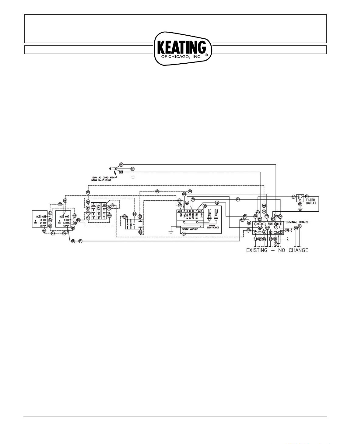
FIG 1. WIRING DIAGRAM FOR IFMs WITH DUAL−ELECTRODE SPARK IGNITION
MODULE (PART # 019724) AND RELIGHT CIRCUIT
SERVICE INSTRUCTIONS
INSTALLATION INSTRUCTIONS FOR SPARK
IGNITION MODULE #037981
For IFMs With Spark Iginition Module Mounted in the Blower Box
www.keatingofchicago.com 1-800-KEATING
SpkIgModInst_037981_BB
9/08
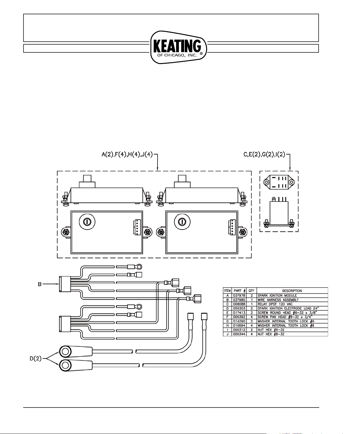
7. Drill holes and mount the two new modules (Part # 037978) keeping in mind the length of the new spark electrode
leads (length: 24”, Part # 037551) and the space occupied by the two modules. Use pan head screws # 8-32 x 3/4”, # 832 hex nuts and internal tooth lock washers #8.
Part # 037983
Part # 037983
 Loading...