

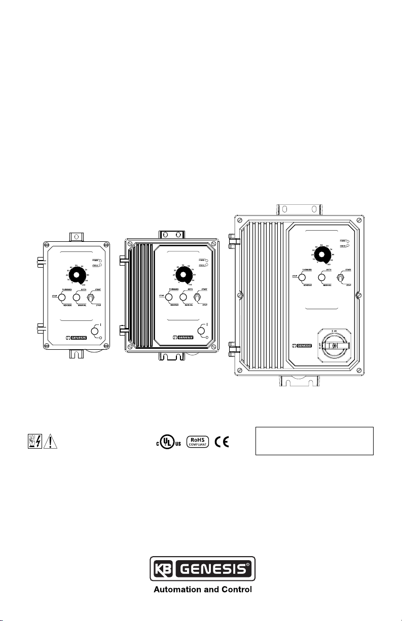
Installation & Operation Manual
KBAC SERIES
Adjustable Frequency Drives for 3-Phase AC Motors
NEMA 4X / IP65
Variable Speed/Soft-Start AC Motor Drive
with Electronic Motor Overload Protection
1
Washdown and Watertight for Indoor and Outdoor Use
Rated for 208 – 230, and 400/460 Volt 50 & 60 Hz
3-Phase & PSC2 AC Induction Motors from Subfractional thru 10 HP
AC MOTOR SPEED CONTROL
Hybrid Drive
KBAC SERIES • NEMA 4X / IP65
3
™
Operates from 115, 208/230 and 400/460 Volt 50/60 Hz AC Line
AC MOTOR SPEED CONTROL
Hybrid Drive
KBAC SERIES • NEMA 4X / IP 65
™
AC MOTOR SPEED CONTROL
Hybrid Drive
KBAC SERIES • NEMA 4X / IP 65
™
This Manual Covers Models
KBAC-24D, 27D, 29, 29 (1P), 45, 48, 217, 217S, 217F, 217SF, 416, 416S, 416F, 416SF
NOTE: THE DRIVE IS FACTORY SET FOR
See Safety Warning
on Page 6.
4
60 Hz MOTORS. FOR 50 Hz MOTORS, SEE
SECTION 6.4 ON PAGE 24.
The information contained in this manual is intended to be accurate. However, the manufacturer retains
the right to make changes in design which may not be included herein.
Notes: 1. UL approved as an electronic overload protector for motors. 2. Special software
is available – contact our Sales Department. 3. GFCI Operation: Models KBAC-24D, 27D, 29,
29 (1P), 45, 48 require custom software – contact our Sales Department. The KBAC-217, 416
Series are jumper selectable (J12) for standard (G1) and sensitive (G2) GFCIs. 4. Installation
of a CE approved RFI lter is required.
©2016 KB Electronics, Inc.
(see back cover)

Table of Contents
Section Page
1 Quick-Start Instructions . . . . . . . . . . . . . . . . . . . . . . . . . . . . . . . . . . . . . . . . . . . . . . . . . . . . . 4
2 Safety Warning . . . . . . . . . . . . . . . . . . . . . . . . . . . . . . . . . . . . . . . . . . . . . . . . . . . . . . . . . . . 6
3 Introduction . . . . . . . . . . . . . . . . . . . . . . . . . . . . . . . . . . . . . . . . . . . . . . . . . . . . . . . . . . . . 6
4 Important Application Information . . . . . . . . . . . . . . . . . . . . . . . . . . . . . . . . . . . . . . . . . . . . . 18
5 Wiring Instructions . . . . . . . . . . . . . . . . . . . . . . . . . . . . . . . . . . . . . . . . . . . . . . . . . . . . . . . 18
6 Setting Selectable Jumpers . . . . . . . . . . . . . . . . . . . . . . . . . . . . . . . . . . . . . . . . . . . . . . . . . . 23
7 Mounting Instructions . . . . . . . . . . . . . . . . . . . . . . . . . . . . . . . . . . . . . . . . . . . . . . . . . . . . . 26
8 Recommended High Voltage Dielectric Withstand Testing (Hi-Pot Testing). . . . . . . . . . . . . . . . . . . . 26
9 Reconditioning the Bus Capacitors . . . . . . . . . . . . . . . . . . . . . . . . . . . . . . . . . . . . . . . . . . . . . 26
10 Drive Operation . . . . . . . . . . . . . . . . . . . . . . . . . . . . . . . . . . . . . . . . . . . . . . . . . . . . . . . . . 28
11 AC Line Fusing . . . . . . . . . . . . . . . . . . . . . . . . . . . . . . . . . . . . . . . . . . . . . . . . . . . . . . . . . . 28
12 Diagnostic LEDs . . . . . . . . . . . . . . . . . . . . . . . . . . . . . . . . . . . . . . . . . . . . . . . . . . . . . . . . . 28
13 Trimpot Adjustments . . . . . . . . . . . . . . . . . . . . . . . . . . . . . . . . . . . . . . . . . . . . . . . . . . . . . . 29
Appendix A – Optional SIAC-PS Signal Isolator with Power Supply . . . . . . . . . . . . . . . . . . . . . . . . . . . 33
Limited Warranty. . . . . . . . . . . . . . . . . . . . . . . . . . . . . . . . . . . . . . . . . . . . . . . . . . . . . . . . . . . 36
Tables Page
1 Jumper Selectable Features. . . . . . . . . . . . . . . . . . . . . . . . . . . . . . . . . . . . . . . . . . . . . . . . . . . 8
2 Optional Accessories . . . . . . . . . . . . . . . . . . . . . . . . . . . . . . . . . . . . . . . . . . . . . . . . . . . . . . . 9
3 General Performance Specications . . . . . . . . . . . . . . . . . . . . . . . . . . . . . . . . . . . . . . . . . . . . 13
4 Electrical Ratings. . . . . . . . . . . . . . . . . . . . . . . . . . . . . . . . . . . . . . . . . . . . . . . . . . . . . . . . . 14
5 Terminal Block Wiring Information . . . . . . . . . . . . . . . . . . . . . . . . . . . . . . . . . . . . . . . . . . . . . 19
6 Drive Operating Condition and Run/Fault Relay Contact Status . . . . . . . . . . . . . . . . . . . . . . . . . . . 23
7 Drive Operating Condition and Status LED Indicator . . . . . . . . . . . . . . . . . . . . . . . . . . . . . . . . . . 29
Figures Page
1 Quick-Start Connection Diagram . . . . . . . . . . . . . . . . . . . . . . . . . . . . . . . . . . . . . . . . . . . . . . . 4
2 KBAC-24D Control Layout . . . . . . . . . . . . . . . . . . . . . . . . . . . . . . . . . . . . . . . . . . . . . . . . . . . 10
3 KBAC-27D, 29, 29 (1P), 45, 48 Control Layout . . . . . . . . . . . . . . . . . . . . . . . . . . . . . . . . . . . . . . . 11
4 KBAC-217, 416 Series Control Layout . . . . . . . . . . . . . . . . . . . . . . . . . . . . . . . . . . . . . . . . . . . . 12
5 Model KBAC-24D Mechanical Specications . . . . . . . . . . . . . . . . . . . . . . . . . . . . . . . . . . . . . . . 15
6 Models KBAC-27D, 29, 29 (1P), 45, 48 Mechanical Specications . . . . . . . . . . . . . . . . . . . . . . . . . . 16
7 KBAC-217, 416 Series Mechanical Specications. . . . . . . . . . . . . . . . . . . . . . . . . . . . . . . . . . . . . 17
8 Maximum Allowed Motor Torque vs. Speed. . . . . . . . . . . . . . . . . . . . . . . . . . . . . . . . . . . . . . . . 18
9 Open Ventilated Motor with External Fan Cooling. . . . . . . . . . . . . . . . . . . . . . . . . . . . . . . . . . . . 18
10 Models KBAC-24D, 27D, 29 (1P), AC Line Input, Motor, and Ground Connections . . . . . . . . . . . . . . . . 20
11 Models KBAC-29, 45, 48 AC Line Input, Motor, and Ground Connections . . . . . . . . . . . . . . . . . . . . . 20
12 KBAC-217, 416 Series AC Line Input, Motor, and Ground Connections . . . . . . . . . . . . . . . . . . . . . . . 20
13 Remote Main Speed Potentiometer Connection. . . . . . . . . . . . . . . . . . . . . . . . . . . . . . . . . . . . . 21
14 Remote Start/Stop Switch Connection with Normally Open Stop Contact . . . . . . . . . . . . . . . . . . . . 21
15 Remote Start/Stop Switch Connection with Normally Closed Stop Contact . . . . . . . . . . . . . . . . . . . 21
16 Start/Stop Function Eliminated . . . . . . . . . . . . . . . . . . . . . . . . . . . . . . . . . . . . . . . . . . . . . . . 22
17 Voltage Following Connections . . . . . . . . . . . . . . . . . . . . . . . . . . . . . . . . . . . . . . . . . . . . . . . 22
18 Enable Circuit Connection. . . . . . . . . . . . . . . . . . . . . . . . . . . . . . . . . . . . . . . . . . . . . . . . . . . 22
19 Run/Fault Relay Output Contacts Connection . . . . . . . . . . . . . . . . . . . . . . . . . . . . . . . . . . . . . . 23
20 Models KBAC-24D, 27D AC Line Input Voltage Selection (Jumper J1) . . . . . . . . . . . . . . . . . . . . . . . 23
21 Removing Jumper J1 on Models KBAC-24D, 27D . . . . . . . . . . . . . . . . . . . . . . . . . . . . . . . . . . . . 23
22 Motor Horsepower Selection (Jumper J2) . . . . . . . . . . . . . . . . . . . . . . . . . . . . . . . . . . . . . . . . . 24
23 Automatic Ride-Through or Manual Restart Selection (Jumper J3) . . . . . . . . . . . . . . . . . . . . . . . . . 24
ii

24 60 Hz and 50 Hz Motor Selection (Jumpers J4 and J5) . . . . . . . . . . . . . . . . . . . . . . . . . . . . . . . . . 24
25 Available Torque vs. Output Frequency . . . . . . . . . . . . . . . . . . . . . . . . . . . . . . . . . . . . . . . . . . 24
26 120 Hz and 100 Hz Drive Output Frequency Selection . . . . . . . . . . . . . . . . . . . . . . . . . . . . . . . . . 25
27 Fixed or Adjustable Boost Selection (Jumper J6). . . . . . . . . . . . . . . . . . . . . . . . . . . . . . . . . . . . . 25
28 Regenerative or DC Injection Braking Selection (Jumper J7) . . . . . . . . . . . . . . . . . . . . . . . . . . . . . 25
29 “Run” or “Fault” Output Relay Operation Selection (Jumper J8). . . . . . . . . . . . . . . . . . . . . . . . . . . . 25
30 Normally Open or Closed Stop Contact Selection (Jumper J9) . . . . . . . . . . . . . . . . . . . . . . . . . . . . 25
31 Constant or Variable Torque Selection (Jumper J10) . . . . . . . . . . . . . . . . . . . . . . . . . . . . . . . . . . 25
32 Switching Frequency and GFCI Selection (Jumper J12) . . . . . . . . . . . . . . . . . . . . . . . . . . . . . . . . 26
33 Typical Hi-Pot Test Setup. . . . . . . . . . . . . . . . . . . . . . . . . . . . . . . . . . . . . . . . . . . . . . . . . . . . 27
34 Minimum Speed Trimpot (MIN) Range . . . . . . . . . . . . . . . . . . . . . . . . . . . . . . . . . . . . . . . . . . . 30
3 Maximum Speed Trimpot (MAX) Range . . . . . . . . . . . . . . . . . . . . . . . . . . . . . . . . . . . . . . . . . . 30
36 Acceleration Trimpot (ACCEL) Range . . . . . . . . . . . . . . . . . . . . . . . . . . . . . . . . . . . . . . . . . . . . 30
37 Deceleration Trimpot (DEC/I) Range . . . . . . . . . . . . . . . . . . . . . . . . . . . . . . . . . . . . . . . . . . . . 30
38 DC Injection Brake Trimpot (DEC/I) Range. . . . . . . . . . . . . . . . . . . . . . . . . . . . . . . . . . . . . . . . . 30
39 Slip Compensation Trimpot (COMP) Range . . . . . . . . . . . . . . . . . . . . . . . . . . . . . . . . . . . . . . . . 30
40 Current Limit Trimpot (CL) Range . . . . . . . . . . . . . . . . . . . . . . . . . . . . . . . . . . . . . . . . . . . . . . 30
41 I2t Trip Time vs. Motor Current . . . . . . . . . . . . . . . . . . . . . . . . . . . . . . . . . . . . . . . . . . . . . . . . 31
42 Boost Trimpot (BOOST) Range . . . . . . . . . . . . . . . . . . . . . . . . . . . . . . . . . . . . . . . . . . . . . . . . 31
43 Jog Trimpot (JOG) Range Run-Stop-Jog Switch Connection . . . . . . . . . . . . . . . . . . . . . . . . . . . . . 32
44 Run-Stop-Jog Switch Connection . . . . . . . . . . . . . . . . . . . . . . . . . . . . . . . . . . . . . . . . . . . . . . 32
Items Included In this Package:
Adjustable Frequency Drive, Installation and Operation Manual, Trimpot Adjustment Tool, CE Approved
Product Information Card, and Warranty Registration Card.
Drive Model Nos. and Part Nos.
Model No.
KBAC-24D 9987 9988 KBAC-217 8868 8879
KBAC-27D 9520 9521 KBAC-217S 8863 8855
KBAC-29 9528 9529 KBAC-217F 8861 8853
KBAC-29 (1P) 10001 10002 KBAC-217SF 8869 8880
KBAC-45 9530 9531 KBAC-416 8870 8881
KBAC-48 9540 9541 KBAC-416S 8864 8856
*White FDA approved nish.
Part No.
Gray White* Gray White*
Model No.
KBAC-416F 8874 8883
KBAC-416SF 8871 8882
Part No.
UL Notice
230 VAC Controls
Suitable For Use on a Circuit Capable of Delivering Not More Than 5 kA RMS Symmetrical Amperes,
230 Volts Maximum.
Use Copper Conductors Rated 75 ºC.
Suitable for Operation in a Maximum Surrounding Air Temperature of 40 ºC.
460 VAC Controls
Suitable For Use on a Circuit Capable of Delivering Not More Than 5 kA RMS Symmetrical Amperes, 460
Volts Maximum.
Use Copper Conductors Rated 75 ºC.
Suitable for Operation in a Maximum Surrounding Air Temperature of 40 ºC.
iii

1 QUICK-START INSTRUCTIONS
see Section 5.2 on page 20.
Models KBAC-416 , 416S, 416F, 416SF see Section 5.1 on pages 19 and 20.
Important – You must read these simplied instructions before proceeding. These instructions
are to be used as a reference only and are not intended to replace the details provided herein.
You must read the Safety Warning on page 5 before proceeding.
Reconditioning the Bus Capacitors – If this drive has been in storage for over one year, it is
necessary to recondition the power supply bus capacitors. To recondition the bus capacitors, apply the
AC Line with the drive in the Stop Mode for a minimum of one hour. Not following this procedure will
cause the bus capacitors to fail.
See Figure 1. Also see Section 4 - Important Application Information on Page 18.
WARNING! Disconnect main power before making connections to the drive.
Figure 1 – Quick-Start Connection Diagram*
TB1
L2
L1V WU L3
AC LINEM OTOR
Motor
208/230 Volt, 1-Phase,
50/60 Hz, AC Line Input
3-Phase
AC Induction Motor:
see Section 5.3 on page 21.
(Terminals L1, L2)
Models KBAC-24D, 27D, 29, 29 (1P):
see Section 5.1 on pages 19 and 20.
Ground (Earth):
208/230 Volt, 3-Phase, 50/60 Hz, AC Line Input (Terminals L1, L2, L3)
Models KBAC-29, 217, 217S, 217F, 217SF see Section 5.1 on pages 19 and 20.
400/460 Volt, 3-Phase, 50/60 Hz, AC Line Input (Terminals L1, L2, L3)
*Layout may vary.
1.1 AC Line Input Connection – Wire the AC Line input to Terminal Block TB1. See Section 5.1
on pages 19 and 20.
Application Note: GFCI Operation: Models KBAC-24D, 27D, 29, 29 (1P), 45, 48 require custom
software – contact our Sales Department. The KBAC-217, 416 Series are jumper selectable
(J12) for Standard (G1) or Sensitive (G2) GFCIs.
Note: The rated AC Line voltage of the drive must match the actual AC Line input voltage. On Models
KBAC-24D and 27D, the setting of Jumper J1 must match the AC Line input voltage.
Models KBAC-24D, 27D, 29 (1P): Designed to accept 1-phase (Terminals L1, L2) AC Line input
only. Rated for 208/230 Volt AC Line input with Jumper J1 set to the “230V” position
(factory setting). Rated for 115 Volt AC Line input with Jumper J1 set to the “115V” position.
See Figure 10 on page 20.
Note: Model KBAC-27D is rated for 1½ HP maximum with 115 Volt AC Line input and 2 HP maximum
with 208/230 Volt AC Line input.
Model KBAC-29: Designed to accept 1-phase (Terminals L1, L2) or 3-phase (Terminals L1, L2, L3)
AC Line input. Rated for 208/230 Volt AC Line input only. See Figure 11 on page 20.
4

Note: Rated for 2 HP maximum with 1-phase AC Line input and 3 HP maximum with 3-phase AC Line
input. For 3 HP rating with single-phase input, use Model KBAC-29 (1P).
Models KBAC-217, 217S, 217F, 217SF: Designed to accept 3-phase (Terminals L1, L2, L3) AC Line
input only. Rated for 208/230 Volt AC Line input only. See Figure 12 on page 20.
Models KBAC-45, 48, 416, 416S, 416F, 416FS: Designed to accept 3-phase (Terminals L1, L2, L3)
AC Line input only. Rated for 400/460 Volt AC Line input only. See Figure 12 on page 20.
1.2 AC Line Fusing – It is recommended that a fuse(s) or circuit breaker be installed in the AC Line.
Fuse each conductor that is not at ground potential. For the recommended fuse size, see Table 4
on page 14. Also see Section 11 on page 28.
1.3 Ground Connection – Connect the ground wire (earth) to the ground screw, as shown in Figures
10 -12 on page 20. See Section 5.2 on page 20.
1.4 Motor Connection – Wire the motor to Terminal Block TB1 Terminals U, V, W, as shown in
Figures 10 -12 on page 20. (Special reactors may be required for cable lengths over 100 ft. (30 m) –
consult our Sales Department.) See Section 5.3 on page 21.
1.5 60 Hz And 50 Hz Motor Operation – The drive is factory set for 60 Hz 3-phase motor operation
(Jumper J5 set to the “60Hz” position). For 50 Hz motor operation, set Jumper J5 to the “50Hz”
position. See Section 6.4 on page 24.
1.6 Start/Stop Switch – The drive is supplied with a prewired Start/Stop Switch to electronically
“start” and “stop” the drive, as described in Section 5.5 on page 21. This switch must be used to
“start” the drive each time the AC Line is applied to the drive or to “restart” the drive. Also see
Section 6.8 on page 25.
1.7 Jumper Settings – All jumpers have been factory set for most applications. However, some
jumpers may need to be set in order to tailor the drive for a specic application. See section 6
on pages 23 – 26.
IMPORTANT: In order to ensure that the motor is properly protected with the I2t Overload
Protection feature, it is required that Jumper J2 is set to the corresponding position for the motor
horsepower being used, as shown in Figure 22 on page 24.
1.8 Trimpot Settings – All trimpots have been factory set for most applications. Some applications require adjustment of the trimpots in order to tailor the drive for a specic requirement. See Section
13 on pages 29 – 32.
1.9 Diagnostic LEDs – After power has been applied, observe the LEDs to verify proper drive
operation, as described in Section 12 on pages 28 and 29.
5

2 SAFETY WARNING
Denition of Safety Warning Symbols
Electrical Hazard Warning Symbol – Failure to observe this warning could result in electrical
shock or electrocution.
Operational Hazard Warning Symbol – Failure to observe this warning could result in serious
injury or death.
This product must be installed and serviced by a qualied technician, electrician, or
Proper installation, which includes electrical connections, fusing or other current protection,
and grounding, can reduce the chance of electrical shocks, and/or res, in this product or
products used with this product, such as electric motors, switches, coils, solenoids, and/or
relays. Do not use this drive in an explosion-proof application. Eye protection must be worn and
insulated adjustment tools must be used when working with drive under power. This product is
constructed of materials (plastics, metals, carbon, silicon, etc.) which may be a potential hazard.
Proper shielding, grounding, and ltering of this product can reduce the emission of radio
frequency interference (RFI) which may adversely aect sensitive electronic equipment. It is the
responsibility of the equipment manufacturer and individual installer to supply this Safety
Warning to the ultimate end user of this product. (SW 8/2012)
required. See RFI Filters & Chokes Selection Guide D-321 (Part No. A42027) for selection of lters that
meet the Industrial or Residential Standard. Additional shielded cable and/or AC Line cables may be
required along with a signal isolator (SIAC-PS).
3 INTRODUCTION
Thank you for purchasing the KBAC Adjustable Frequency Drive. KB Electronics, Inc. is committed to pro-
viding total customer satisfaction by producing quality products that are easy to install and operate. The
KBAC is manufactured with surface mount components incorporating advanced circuitry and technology.
The drives are variable speed controls housed in a rugged NEMA 4X / IP65 washdown and watertight
die-cast aluminum enclosure. They are designed to operate 208 – 230 and 400/460 Volt 50 & 60 Hz
3-phase AC induction motors from subfractional thru 10 HP. The sine wave coded Pulse Width Modulated
(PWM) output operates at a carrier frequency of 16 kHz which provides high motor eciency and low
noise. Adjustable Linear Acceleration and Deceleration are provided, making the drive suitable for
soft-start applications.
Due to its user-friendly design, the KBAC AC drive is easy to install and operate. Tailoring to specic
applications is accomplished with selectable jumpers and trimpots, which eliminate the computer-like
programming required on other drives. However, for most applications no adjustments are necessary.
Main features include adjustable RMS Current Limit and I2t Motor Overload Protection.* In addition,
Adjustable Slip Compensation with Static Auto-Tune and Boost provides high torque and excellent
load regulation over a wide speed range. Power Start™ delivers over 200% motor torque to ensure
start-up of high frictional loads. Electronic Inrush Current Limit (EICL™) eliminates harmful AC Line inrush
current. A Run/Fault Relay is provided, which can be used to turn equipment on or o , to signal a
warning if the drive is put into the Stop Mode, or if a fault has occurred. The drive is suitable for machine
or variable torque (HVAC) applications. Also, a jumper is provided for selection of Regenerative or
DC Injection Braking.
Standard front panel features include Diagnostic LEDs for “Power On” and “Drive Status”, a Start/Stop
Switch, and a Main Speed Potentiometer. Other features include a Barrier Terminal Block to facilitate
wiring of the AC Line and motor, adjustable trimpots (MIN, MAX, ACCEL, DEC/I, COMP, CL, JOG, BOOST),
customer selectable jumpers (Line Voltage - dual voltage models only), Motor Horsepower, Automatic
Ride-Through / Manual Start, Motor Frequency, Frequency Multiplier, Fixed/Adjustable Boost, Regenerative / Injection Braking, “Run” or “Fault” Output Relay Operation, NO/NC Stop Contact, Constant/Variable
Torque, Switching Frequency, and GFCI operation (KBAC-217 Series and KBAC-416 Series only).
electrical maintenance person familiar with its operation and the hazards involved.
This product complies with all CE directives pertinent at the time of manufacture. Contact our
Sales Department for Declaration of Conformity. Installation of a CE approved RFI lter is
6

Optional accessories include: Forward-Stop-Reverse Switch, On/O AC Line Switch, Run-Stop-Jog Switch,
Signal Isolator, Auto/Manual Switch, Class ”A” AC Line Filter, Multi-Speed Board and Liquidtight Fittings.
A connector is provided for easy installation of accessories. Custom software: all models can be factory
programmed for applications which require special timing, PLC functions, and GFCI operation
(Models KBAC-24D, 27D, 29, 29 (1P), 45, 48) – contact our Sales Department.
*UL approved as an electronic overload protector for motors.
3.1 Standard Features
• Industrial Duty Die-Cast Aluminum Case with Hinged Cover – Available in Dark Gray nish or
FDA approved white nish.
• Simple to Operate – Does not require programming. Uses trimpots and jumpers, which are
factory set for most applications.
• Motor HP Selection Jumper (J2) – Allows the drive to be used on a wide range of motors
without recalibration.
• Switching Frequency and GFCI Selection Jumper (J12) – Allows the drive to be operated
at 8 kHz or 12 kHz and on Standard (G1) or Sensitive (G2) GFCIs. (KBAC-217 Series and
KBAC-416 Series only.)
• Diagnostic LEDs – Power on (POWER) and drive status (STATUS).
• Run/Fault Relay Output Contacts – Can be used to turn equipment on or o, to signal a warning
if the drive is put into the Stop Mode, or a fault has occurred.
• Start/Stop Switch – Provides electronic start and stop functions.
• Barrier Terminal Block – Facilitates wiring of motor, AC Line, and Run/Fault Relay Output Contacts.
• Jumper Selection of Drive Output Frequency – Increases the motor speed up to two times the
rated RPM.
• Ride-Through – Provides smooth recovery to the previous set speed during a momentary power
loss (of less than 2 seconds).
• Holding Torque at Zero Speed – Resists motor shaft rotation when the drive is in Stop Mode.
Note: GFCI Operation: Models KBAC-24D, 27D, 29, 29 (1P), 45, 48 require custom software – contact
our Sales Department. The KBAC-217 Series and KBAC-416 Series are jumper selectable (J12) for Standard (G1) or Sensitive (G2) GFCIs.
3.2 Performance Features
• Power Start™ – Provides more than 200% starting torque which ensures startup of high frictional loads.
• Slip Compensation with Static Auto-Tune and Boost – Provides excellent load regulation over
a wide speed range.
• Speed Range – 60:1
3.3 PROTECTION FEATURES
• Motor Overload (I2t) with RMS Current Limit* – Provides motor overload protection which
prevents motor burnout and eliminates nuisance trips.*
• Electronic Inrush Current Limit (EICL™) – Eliminates harmful Inrush AC Line current during startup.
• Short Circuit – Shuts down the drive if a short circuit occurs at the motor (phase-to-phase).
• Regeneration – Eliminates tripping due to high bus voltage caused by rapid deceleration of high
inertial loads.
• Undervoltage and Overvoltage – Shuts down the drive if the AC Line input voltage goes above
or below the operating range.
• MOV Input Transient Suppression – Protects the drive components against damaging voltage
spikes on the AC Line.
• Microcontroller Self Monitoring and Auto Reboot.
*UL approved as an electronic overload protector for motors.
7

3.4 TRIMPOT ADJUSTMENTS
• Minimum Speed (MIN) – Sets the minimum speed of the motor. See Section 13.1 on page 29.
• Maximum Speed (MAX) – Sets the maximum speed of the motor. See Section 13.2 on page 29.
• Acceleration (ACCEL) – Sets the amount of time for the motor to accelerate from zero speed to
full speed. See Section 13.3 on page 29.
• Deceleration (DEC/I) – Sets the amount of time for the motor to decelerate from full speed to
zero speed. See Section 13.4 on page 27.
• DC Injection Brake (DEC/I) – When the drive is set for DC Injection Braking (Jumper J7 set to
the “INJ” position), the DEC/I trimpot is used to set the DC Injection Brake voltage and time.
See Section 13.5 on pages 29 and 30.
• Slip Compensation (COMP) – Maintains set motor speed under varying loads. See Section 13.6
on page 30.
• Current Limit (CL) – Sets the current limit (overload) which limits the maximum current to the
motor. See Section 13.7 on pages 30 and 31.
• Boost (BOOST) – Sets the amount of Boost which can be used to obtain maximum low speed
performance. See Section 13.8 on pages 31 and 32.
• Jog (JOG) – Sets the “jog” speed of the motor. Must be used with the optional Run-Stop-Jog
Switch Kit (See Table 2 on page 9). See Section 13.9 on page 32.
Table 1 – Jumper Selectable Features
1
Description
AC Line Input Voltage (115, 230) J1
Motor Horsepower (see Table 4 - Electrical Ratings on page 14) J2
Automatic Ride-Through or Manual Restart (A2, M) J3
Frequency Multiplier (1X, 2X) J4
Motor Frequency (50Hz, 60Hz) J5
Fixed or Adjustable Boost (FIX, ADJ) J6
Regenerative or DC Injection Braking (RG, INJ) J7
“Run” or “Fault” Output Relay Operation (R, F) J8
Normally Open or Closed Stop Contact (NO, NC) J9
Constant or Variable Torque (VT, CT) J10
Factory Use Only J11 — — —
Switching Frequency and GFCI (8 kHz, 12 kHz, G1, G2) J12 — —
Notes: 1. Bold indicates factory setting. 2. In Automatic Ride-Through Mode, the drive will automatically restart due to a momentary power loss of
less than 2 seconds.
PC Board
Designation KBAC-24D, 27D KBAC-29, 29 (1P), 45, 48
p
p p p
p p p
p p p
p p p
p p p
p p p
p p p
p p p
p p p
— —
KBAC-217 Series
KBAC-416 Series
p
8

Table 2 – Optional Accessories
Description KBAC-24D KBAC-27D KBAC-29 KBAC-29 (1P) KBAC-45 KBAC-48
Forward-Stop-Reverse Switch – Provides motor
reversing and stop functions. Mounts on the enclosure
cover and is supplied with a switch seal to maintain
liquidtight integrity.
On/O AC Line Switch – Disconnects the AC Line.
Mounts on the enclosure cover and is supplied with a
switch seal to maintain liquidtight integrity.
Run-Stop-Jog Switch – Selects speed
setting from either the Main Speed Potentiometer or
the JOG Trimpot. Mounts on the enclosure cover and
is supplied with a switch seal to maintain liquidtight
integrity.
SIAC-PS Signal Isolator with Power Supply –
Provides isolation between a non-isolated signal source
and the drive. Mounts on the drive’s PC board with
four snap-ins.
Auto/Manual Switch – When used with the Signal
Isolator, it selects remote process signal or the Main
Speed Potentiometer. Mounts on the enclosure
cover and is supplied with a switch seal to maintain
liquidtight integrity.
AC Line Filter* – Provides Class A RFI (EMI)
suppression. Installs onto the drive’s PC board
with quick-connect terminals.
“S” Sux: Filter is used when On/O AC Line
Switch is installed.
“NS” Sux: Filter is used when On/O AC Line
Switch is not installed.
Liquidtight Fittings – Provide a liquidtight seal for
wiring the drive. Kit includes three 1/2” and one 3/4”
liquidtight ttings for case A and case B drives, and one
1/2” and two 3/4” liquidtight ttings for case C drives.
* Complies with CE Council Directive 89/336/EEC Industrial Standard.
9480 9480 9480 9480 9480 9480 8888
9482 9523 9532 9532 9532 9532
9340 9340 9340 9340 9340 9340 8889
9600C* 9600C* 9600C* 9600C* 9600C* 9600C* 8890
9481 9481 9481 9481 9481 9481 8891
“S”
9507 9512 9479 — 9479 9479
Sux
“NS”
9507 9512 9515 — 9515 9515
Sux
9526 9526 9526 9526 9526 9526 8892
KBAC-217 Series
KBAC-416 Series
“S” Sux Models
(Factory Installed
Only)
9516
*Warning! It is highly recommended that the SIAC-PS Signal Isolator with Power Supply be
installed when using the drive with external control signals. See Appendix A, on Page 33,
for more information.
9
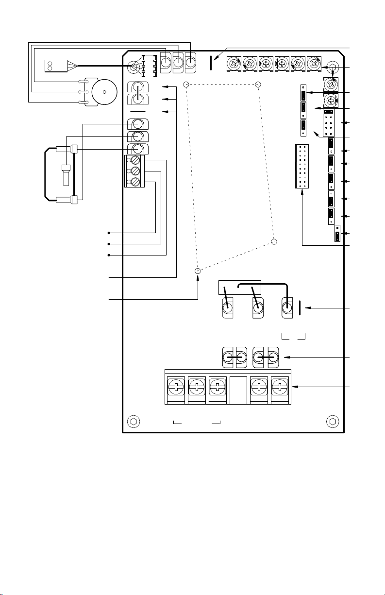
Figure 2 – KBAC-24D Control Layout
LED Board
See Section 12 on page 23.
POWER
STATUS
Violet (High)
Orange (Wiper)
White (Low)
Main Speed Potentiometer
See Section 5.4 on page 21.
Start/Stop Switch
See Section 5.5 on page 21.
Run/Fault Relay
Output Contacts
See Section 5.9 on page 23.
Used for optional
Forward-Stop-Reverse Switch.
See Table 2 on page 9.
Used for optional
SIAC Signal Isolator.
See Table 2 on page 9.
White
Black
Red
TB2
N.C.
COM
N.O.
CON2
FWD
COM
REV
RUN
COM
STOP
MAX ACCEL DECELMIN CLBOOST
MAX MIN ACCEL DEC/I BOOST
JOGP1P2P3
B- B+
(BLK)
(RED)
A
JOGCOMP
J6
J7
J8
J9
J10
B
C
COMP JOG
D
1HP
3/4
1/2
E
1/4
1/8
F
FIX
BST
ADJ
G
RG
H
INJ
R
I
RELAY
F
NC
J
STOP
NO
CT
K
VT
2
J11
L
1
M
CL
MAN
J3
AUTO
1X
MULT
J4
2X
60HZ
J2
J5
FREQ
50HZ
CON1
N
115V
230V
J1
L2BL2AL1BL1A
O
P
TB1
WVU
MOTOR
L1 L2
AC LINE
All jumpers and trimpots are shown in factory set positions.
A – JOG Terminal. Used with optional Run/Jog Switch Kit.
See Table 2 on page 9.
B – Adjustable trimpots. See Section 13 on Pages 29 - 32.
C – J3: Automatic Ride -Through or Manual Restart selection.
See S ection 6.3 on page 23.
E – J2: Motor Horsepower selection.
See S ection 6.2 on pages 23 and 24.
D – J4: 1X or up to 2X Rated Motor RPM Operation selection.
See S ection 6.4 on page 24.
G – J6: Fixed or Adjustable Boost selection.
See S ection 6.5 on page 24.
F – J5: 60 Hz or 50 Hz Motor Operation selection.
See S ection 6.4 on page 24.
H – J7: Regenerative or Injection Braking selection.
10
See S ection 6.6 on page 25.
I – J8: Run or Fault Output Relay Operation selection.
See S ection 6.7 on page 25.
J – J9: Normally Open or Closed Stop Contact selection.
See S ection 6.8 on page 25.
L – J11: Not used.
K – J10: Constant or Variable Torque selection.
See S ection 6.9 on page 25.
M – CON1: Used to connect optional accessories to the drive.
See Table 2 on page 9.
N – J1: AC Line Input Voltage selection. (Models KBAC-24D, 27D only.)
See S ection 6.1 on page 23.
O – L1A/L1B and L2A/L2B: For optional On/O AC Line Switch.
See Table 2 on page 9.
P – TB1: Motor and AC Line input connections.
See S ections 5.1 - 5.3 on pages 19 - 21.
Start/Stop Switch
Orange (Wiper)
Main Speed Potentiometer
E 1/2
All jumpers and trimpots are shown in factory set positions.
C 1
D 3/4
B 1 1/2
A 2
CT
VT
2 B
ADJ
FIXJ6RG
INJJ7R
FJ8NC
NO
1 A
J2
J9
J10
M
AJ32X
1XJ460Hz
50Hz
J11
J5
CON1
1
MIN ACCELMAX CLDECEL BOOST JOG COMP
MIN ACCELMAX CLDEC/I BOOST JOG COMP
*On Model KBAC-27D, J11 is Labeled "A" , "B"
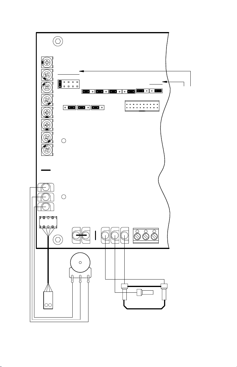
Figure 3 – KBAC-27D*, 29, 29 (1P), 45, 48 Control Layout
CON2
LED Board
STATUS
POWER
JOG
P1P2P3
Violet (High)
FWD
*On Model KBAC-27D, J12 is Labeled "2", "1 1/2", "1", "3/4", "1/2"
COM
REV
RUN
COM
STOP
N.C.
N.O.
COM
TB2
Red
Black
White
White (Low)
11

Start/Stop Switch
LED Board
Main Speed
Potentiometer
All jumpers and trimpots are shown in factory set positions.
KBAC-217, 416 Series only.
See Section 6.11
J12: Switching Frequency
and GFCI selection.
Figure 4 – KBAC-217, 416 Series Control Layout
COMPCL
JOG
BOOST
MIN ACCELMAX DEC/I
CON3
COMP
JOG
BOOST
MIN ACCELMAX CLDEC/I
COMSTOP RUN
J3
CON6
CON5
CON4
CON2
CON1
CON7
J2
CBA
8K
12K
1X2X
AUTO MAN
J4
J5
FIX
ADJ
50Hz 60Hz
J6
J7
RG
INJ
G1
J8
G2
J12
VT CT
J10
J11
21
CON8
RF
NO NC
J9
FWD
REV
COM
P3
P2
JOG
P1
N.C.
CON9
TB2
N.O.
COM
on pages 25 and 26.
12

Table 3 – General Performance Specications
Description Specication Factory Setting
115 Volt AC Line Input Voltage Operating Range (Volts AC) 115 (±15%) —
208/230 Volt AC Line Input Voltage Operating Range (Volts AC) 208 (-15%) / 230 (+15%) —
400/460 Volt AC Line Input Voltage Operating Range (Volts AC) 380 (-15%) – 460 (+15%) —
Maximum Load (% Current Overload for 2 Minutes) 150 —
Switching Frequency (kHz) (Jumper J12) (KBAC-217, 416 Series Only) 8, 12 —
Signal Following Input Voltage Range
Output Frequency Resolution (Bits, Hz) 10, 0.06 —
Minimum Speed Trimpot (MIN) Range (% Frequency Setting) 0 – 40 0
Maximum Speed Trimpot (MAX) Range (% Frequency Setting) 70 – 110 100
Acceleration Trimpot (ACCEL) and Deceleration Trimpot (DEC/I) Range (Seconds) 0.3 – 20 1.5
Boost Trimpot (BOOST) Range (Volts/Hz) 0 – 30 5
Slip Compensation Trimpot (COMP) Range at Drive Rating (Volts/Hz) 0 – 3 1.5
Current Limit Trimpot (CL) Range (% Full Load) 40 – 200 160
Jog Trimpot (JOG) Range (% Frequency Setting) 0 – 100 35
Motor Frequency Setting (Hz) (Jumper J5) 50, 60 60
Output Frequency Multiplier (1X, 2X) (Jumper J4)
Minimum Operating Frequency at Motor (Hz) 1 —
Speed Range (Ratio) 60:1 —
Speed Regulation (30:1 Speed Range, 0 – Full Load) (% Base Speed)
Overload Protector Trip Time for Stalled Motor (Seconds) 6 —
Undervoltage/Overvoltage Trip Points for 115 Volt AC Line Input (± 5%) (Volts AC)⁴ 76 – 141 —
Undervoltage/Overvoltage Trip Points for 208/230 Volt AC Line Input (± 5%) (Volts AC)
Undervoltage/Overvoltage Trip Points for 400/460 Volt AC Line Input (± 5%) (Volts AC)
Run/Fault Relay Output Contact Rating (Amps at 30 Volts DC, 125 Volts AC, 250 Volts AC) 1, 0.5, 0.25 —
Operating Temperature Range (°C / °F)
Operating Humidity Range (% Relative, Non-Condensing) 0 – 95 —
Storage Temperature Range (°C / °F) -2.5 – +85 / -13 – +185 —
Notes: 1. Requires an isolated signal. If a non-isolated signal is used, or if using 0 to ±2.5 thru 0 to ±25 Volts DC, or 4 – 20 mA DC signal input, install
the SIAC-PS Signal Isolator with Power Supply. 2. Allows the motor to operate up to two times the rated RPM. Constant horsepower will result when operating
the drive in the “X2” mode above the motor rated frequency. 3. Dependent on motor performance. 4. Do not operate the drive outside
the specied AC Line input voltage operating range. 5. See Table 4 on page 14.
1
(Volts DC) 0 – 5 —
2
3
4
4
5
1, 2 1
2.5 —
151 – 282 —
302 – 567 —
0 – 40 / 32 – 104 —
13

Table 4 – Electrical Ratings
Fuse or
Max.
Part No. Max. HP
Model No.
Gray White1HP kW lbs kg
KBAC-24D 9987 9988 1 0.75
KBAC-27D 9520 9521
4
KBAC-29 (1P)
10001 10002 3 2.25 208/230 1 20.5 25 0 - 208/230 9 3 2 1½ 1 3/4
KBAC-29 9528 9529
KBAC-4569530 9531 3 2.25 400/460 3 7.2 10 0 – 400/460 5.5 3 2 1½ 1 3/4
6
KBAC-48
9540 9541 5 3.75 400/460 3 11 15 0 – 400/460 8.3 5 3 2 1½ 1
AC Line
Voltage
Phase
(50/60 Hz)
1½ 1.13 115
2 1.5 208/230 16.7 20 6.7 2
2 1.5
3 2.25 3 11.7 15 9 3
(Ø)
(Amps AC)
115
208/230 8.1 15
1
1
208/230
1 16.7 20
AC Line
Current
14.4 20
22 25
Circuit
Breaker
Rating
(Amps)
Voltage
(Volts AC)
Range
Max. Load
Current
(Amps/Phase)
0 - 208/230 3.6 1 3/4 1/2 1/4 1/8 5.9 2.7
0 - 208/230
0 - 208/230
5.5 –
6.7 –
KBAC-217 8868 8879
KBAC-217S 8863 8855
KBAC-217F 8861 8853
5 3.75 208/230 3 22.1 25 0 - 208/230 17 5 3 2
KBAC-217SF 8869 8880
KBAC-416 8870 8881
KBAC-416S 8864 8856
KBAC-416F 8874 8883
10 7.5 400/460 3 20.8 25 0 – 400/460 16 10 7.5 5
KBAC-416SF 8871 8882
Notes: 1. White FDA approved nish. 2. Bold indicates factory setting. On Model KBAC-24D, Jumper J2 is labeled “1”, “3/4”, “1/2”, “1/4”, “1/8” (factory set to the
“1” position).On Model KBAC-27D, Jumper J2 is labeled “2”, “1½”, “1”, “3/4”, “1/2” (factory set to the “1½” position). On Models KBAC-29, 45, 48, Jumper J2 is
labeled “A”, “B”, “C”, “D”, “E” (factory set according to the table). 3. Model KBAC-27D is rated 1½ HP maximum with 115 Volt AC Line input and 2 HP maximum
with 208/230 Volt AC Line input. 4. Model KBAC-29 (1P) is rated 9 Amps at 35 °C / 95 °F and derated to 8.3 Amps at 40 °C / 104 °F. For ambient temperatures
above 40 °C / 104 °F, the drive is derated 2.5% per °C. 5. Model KBAC-29 is rated 2 HP maximum with single-phase AC Line input and 3 HP maximum with
3-phase AC Line input. 6. Models KBAC-45, 48, KBAC-217 Series and KBAC-416 Series are rated 0 – 400 Volts AC for 50 Hz motor operation and 0 – 460 Volts
AC for 60 Hz motor operation.
Motor
Horsepower
Selection2
(Jumper J2)
3
1½
1 3/4 1/2 10.3 4.7
3
A B C D E
5
1½ 1 3/4
2
5
A B C
Net Wt.
10.3 4.7
22 10
14
5.51
Figure 5 – Model KBAC-24D Mechanical Specications (Inches/mm)
140
5.06
0.31
7.97
2X Ø
4* 1*
129
0.25
2.53
6.4 64.4
AC MOTOR SPEED CONTROL
Hybrid Drive
™
8.85
225
KBAC SERIES • NEMA 4X / IP 65
2* 3*
*Tight en these screw s, in the sequence sho wn, to 1 2 in-lbs (1 4 kg-cm).
2.70
68.6
1.35
34.3
1.35
34.3
8.20
208
9.53
242
3X
0.875
22.2
2.76
70.1
5.97
152
15

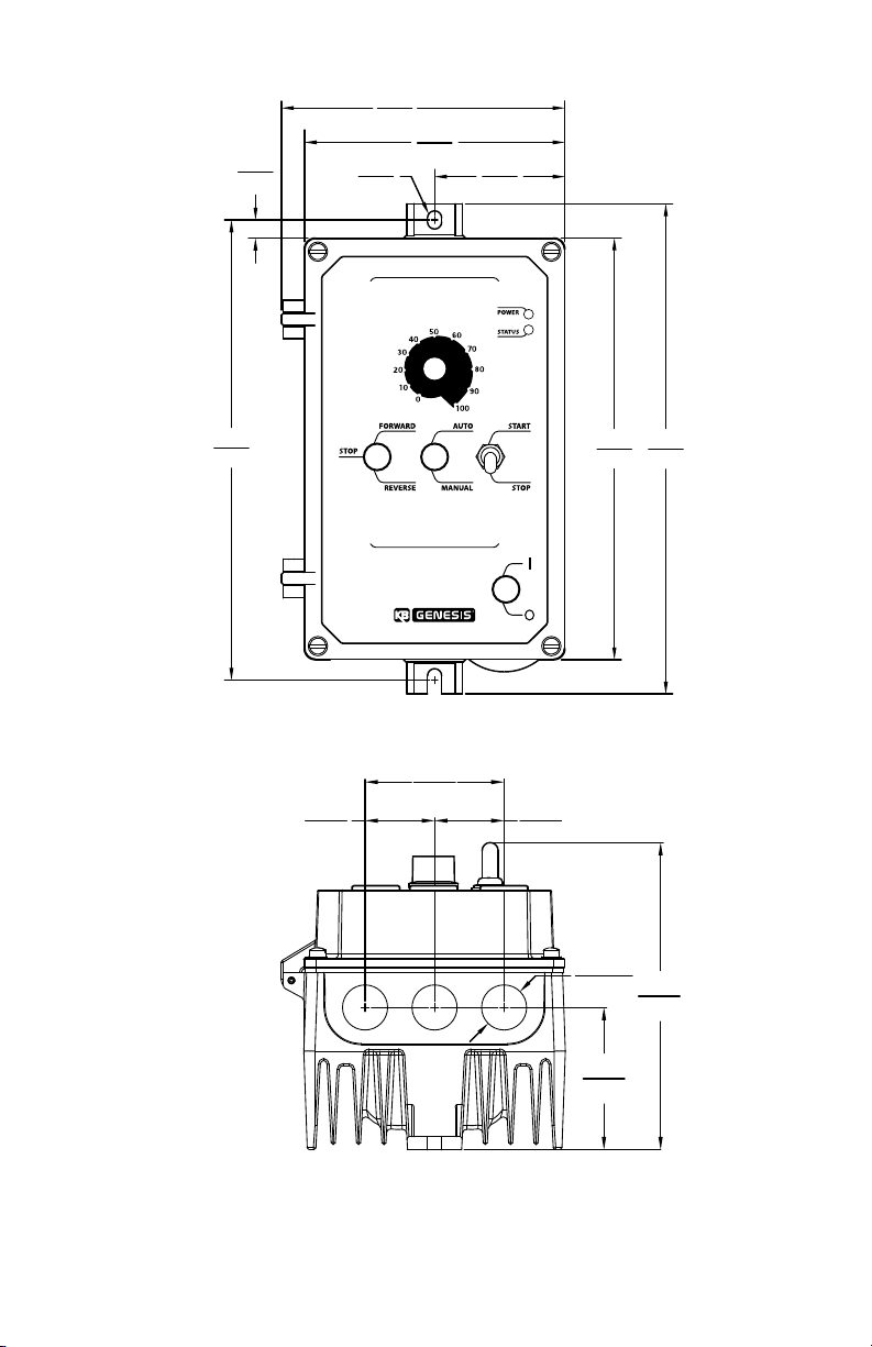
Figure 6 – Models KBAC-27D, 29, 29 (1P), 45, 48 Mechanical Specications (Inches/mm)
3.15
2X
™
1.00
25.4
80.0
0.25 0.29
4X Ø
6.4
4* 1*
2* 3*
AC MOTOR SPEED CONTROL
2X
Hybrid Drive
KBAC SERIES • NEMA 4X / IP 65
7.30
185
7.69
195
*Tight en these screw s, in the sequence sho wn, to 1 2 in-lbs (1 4 kg-cm).
3.20
81.3
1.60
40.6
1.60
40.6
2X
7.37
8.67
220
9.24
235
9.82
249
1.09
22.2
2X
7.36
187
3.07
77.9
0.875
22.2
2.97
75.4
16

Figure 7 – KBAC-217, 416 Series Mechanical Specications (Inches/mm)
*Tighten these screws, in the sequence shown, to 12 in-lbs (14 kg-cm).
0.313
2.25
3.822
0.346
4X Ø
7.95
57.2
2X
97.1
6*
AC MOTOR SPEED CONTROL
Hybrid Drive
™
2*
KBAC SERIES • NEMA 4X / IP65
4*
4.087
2X
104
9.89
251
1.72
43.7
10.3
262
2X
3*
12.235
311
1*
5*
Models without "S" Sux:
Models with "S" Sux:
8.79
13.175
13.825
335
351
MAXIMUM DRIVE DEPTH
8.5
216
9.0
227
1.72
43.7
1.60
40.6
2X Ø
1.08
27.4
0.875
Ø
22.2
9.0
227
3.97
100
17

4 IMPORTANT APPLICATION INFORMATION
Maximum Allowed
100
Motor Speed (%)
100
Airow
4.1 Motor With External Fan Cooling – Most totally enclosed fan-cooled (TEFC) and open ventilated
3-phase AC induction motors will overheat if used beyond a limited speed range at full torque.
Therefore, it is necessary to reduce motor load as speed is decreased.
Note: Some fan-cooled motors can be used over a wider speed range. Consult the motor manufacturer
for details.
WARNING! Some motors have low speed characteristics which cause overheating and
winding failure under light load or no load conditions. If the motor is operated in this manner
for an extended period of time, it is recommended that the unloaded motor current be checked
from 2 – 15 Hz (60 – 450 RPM) to ensure motor current does not exceed the nameplate rating.
Do not use motor if the motor current exceeds the nameplate rating.
It is recommended that the drive be used with Inverter Duty or TENV motors.
Inverter duty and most
totally enclosed non-
Figure 8 – Maximum Allowed Motor Torque vs. Speed
ventilated (TENV) motors can
provide full rated torque over
an extended speed range
without overheating.
See Figure 8.
If external fan cooling is
provided, open ventilated
motors can also achieve
an extended speed range
at full rated torque. A box
fan or blower with a
Motor Torque (%)
80
60
40
20
0
Inverter Duty
and TENV Motors
Fan Cooled
TEFC and Open Ventilated
Motors
60 70 805030 40100 20 90
minimum of 100 CFM per
HP is recommended. Mount
the fan or blower so the
motor is surrounded by the
Figure 9 – Open Ventilated Motor with External Fan Cooling
airow. See Figure 9.
4.2 Electronic Motor Overload
Protection – The drive
contains Modied I2t
Overload Protection.* Part
of this function consists of
a Current Limit (CL) circuit,
Open Ventilated Motor
which limits the drive
current to a factory preset
level of 160% of the rated
drive current. The CL
Trimpot is used to
recalibrate the drive
current from 60% thru 200%. The Power Start™ circuit provides an overshoot function that allows
most motors to develop more than 200% of starting torque and breakdown torque.
Standard I2t is undesirable because it causes nuisance tripping. It allows a very high motor current
to develop and will turn the drive o after a short period of time. KB’s RMS Current Limit Circuit
avoids this nuisance tripping while providing maximum motor protection.
If the motor is overloaded to 120% of full load (75% of the CL setting), the I2t Timer starts. If the
motor continues to be overloaded at the 120% level, the timer will shut down the drive after 30
minutes. If the motor is overloaded to 160% of full load, the drive will trip in 6 seconds.
*UL approved as an overload protector for motors.
Fan or Blower
(100 CFM Min.
per HP)
18

5 WIRING INSTRUCTIONS
WARNING! Read Safety Warning, on page 6, before using the drive. Disconnect main
power before making connections to the drive. To avoid electric shock, be sure to properly
ground the drive. It is highly recommended that the SIAC-PS Signal Isolator with Power Supply
(Part No. 9600C) be installed when using signal following.
WARNING! HIGH VOLTAGE – REMOTE CONNECTIONS OF POTENTIOMETER, SWITCHES, ETC.,
WILL HAVE WIRING THAT IS AT LINE POTENTIAL. IT IS REQUIRED THAT THE SIGNAL ISOLATOR
BE INSTALLED FOR REMOTE CONNECTIONS.
Application Note – To avoid erratic operation, do not bundle the AC Line and motor wires with each
other or with wires from signal following, start/stop contacts, or any other signal wires. Also, do not
bundle motor wires from multiple drives in the same conduit. Use shielded cables on all signal wiring
over 12” (30 cm). The shield should be earth grounded on the drive side only. Wire the drive in
accordance with the National Electrical Code requirements and other local codes that may apply.
Be sure to properly fuse each AC Line conductor that is not at ground potential. Do not fuse neutral or
grounded conductors. A separate AC Line switch or contactor must be wired as a disconnect so that
each ungrounded conductor is opened. For fuse or circuit breaker selection, see Table 5. Also see
Section 11 on page 28.
To maintain the watertight integrity of the drive, be sure to use suitable liquidtight ttings and
wiring which are appropriate for the application. Model KBAC-24D contains three holes for standard
1/2” liquidtight ttings (not supplied) (one 1/2” watertight hole plug is provided). Models KBAC-27D,
29, 29 (1P), 45, 48 contain two holes for standard 1/2” liquidtight ttings (not supplied) and one hole
for standard 3/4” liquidtight tting (not supplied) (one 1/2” watertight hole plug is provided).
The KBAC-217, 416 Series contain one hole for standard 1/2” liquidtight ttings (not supplied)
and two holes for standard 3/4” liquidtight ttings (not supplied) (one 1/2” watertight hole plug
is provided).
The drive is designed with a hinged case so that when the front cover is open, all wiring stays intact.
To open the cover, the four screws must be loosened so they are no longer engaged in the case
bottom. After mounting and wiring, close the cover making sure that the wires do not get caught
or crimped as the cover is closed. Tighten the four screws so that the gasket is slightly compressed.
The recommended tightening torque is 12 in-lbs (14 kg-cm). See Figures 5, 6 and 7 on pages 15-17
for the tightening sequence. Do not overtighten.
Table 5 – Terminal Block Wiring Information
Terminal
Block Description Model
TB1
TB2
AC Line Input and
Motor Wiring
Run/Fault Relay
Output Contacts
KBAC-24D 12 3.3 7 8
KBAC-27D, 29, 29 (1P), 45, 48 12 3.3 12 14
KBAC-24D, 27D, 29, 29 (1P), 45, 48 14 2.08 3.5 4
KBAC-217, 416 Series 12 3.3 4.4 5
5.1 AC Line Input Connection – Wire the AC Line input to Terminal Block TB1.
GFCI Operation: Models KBAC-24D, 27, 29, 29 (1P), 45, 48 require custom software – contact
our Sales Department. The KBAC-217, 416 Series are jumper selectable (J12) for Standard
(G1) or Sensitive (G2) GFCIs.
Note: The rated AC Line voltage of the drive must match the actual AC Line input voltage. On Models
KBAC-24D, 27D, the setting of Jumper J1 must match the AC Line input voltage.
Maximum Wire Size (Cu) Recommended Tightening Torque
AWG mm
2
in-lbs kg-cm
19

Models KBAC-24D, 27D: Designed to
Model KBAC-29 Only
TB1
MOTOR
AC Line Input
Ground (Earth)
TB1
TB1
KBAC-416 Series: 400/460 Volts AC
accept 1-phase AC Line input only
(Terminals L1, L2). Rated for 208/230 Volt
AC Line input with Jumper J1 set to the
“230V” position (factory setting). Rated
for 115 Volt AC Line input with Jumper J1
set to the “115V” position. See Figure 10.
Model KBAC-29: Designed to accept
1-phase (Terminals L1, L2) or 3-phase
(Terminals L1, L2, L3) AC Line input.
Rated for 208/230 Volt AC Line input
only. See Figure 11.
Model KBAC-29(1P): Designed to
accept 1-phase AC Line input
(Terminals L1, L2). Rated for
208/230 Volt AC Line input only.
See Figure 10.
Figure 10 – Models KBAC- 24D, 27D*, 29 (1P)
AC Line Input, Motor, and Ground Connections
VU W
Motor
*Model KBAC-27D is rated 1½ HP maximum with 115 Volt AC Line input and
2 HP maximum with 208/230 Volt AC Line input.
Figure 11 – Models KBAC-29*, 45, 48 AC Line Input, Motor, and Ground Connections
Wire the single-phase AC Line input
to Terminals "L1", "L2", as shown below.
L1 L2
115, 208/230 Volt
Single-Phase
AC LINE
WU V
MOTOR
Motor
L1 L3L2
AC LINE
208/230, 400/460 Volt
AC Line Input
Ground (Earth)3-Phase, 50/60 Hz
208/230 Volt
Single-Phase, 50/60 Hz
AC Line Input
*Note: Model KBAC-29 is rated 2 HP maximum with 1-phase AC Line input and 3 HP maximum with 3-phase AC Line input.
Models KBAC-45, 48: Designed to
accept 3-phase AC Line input only
(Terminals L1, L2, L3). Rated for
400/460 Volt AC Line input only.
See Figure 11.
KBAC-217 Series: Designed to accept
3-phase (Terminals L1, L2, L3) AC Line
input. Rated for 208/230 Volt AC Line
input only. See Figure 12.
KBAC-416 Series: Designed to accept
3-phase (Terminals L1, L2, L3) AC Line
input. Rated for 400/460 Volt AC Line
Input only. See Figure 12.
5.2 Ground Connection – Connect the
Ground Wire (Earth) to the Green
Ground Screw. The Ground Screw is
located next to Terminal Block TB1.
See Figures 10 -12.
Figure 12 – KBAC-217, 416 Series
AC Line Input, Motor, and Ground Connections
U W
V
MO TOR
Chassis
Ground
Motor
20
AC LINE
Chassis
Ground
(Earth)(Earth)
L3L2L1
Ground (Earth)
L1 L2 L3
AC LINE
3-phase, 50/60 Hz AC Line Input
KBAC-217 Series: 208/230 Volts AC

5.3 Motor Connection – Wire the motor to Terminal
Block TB1 Terminals U, V, W. See Figures 10 -12 on
page 20. Motor cable length should not exceed
100 ft (30 m) – special reactors may be required –
consult our Sales Department.
Be sure Jumper J2 is set to the corresponding
motor horsepower rating, as described in
Section 6.2 on page 23.
5.4 Remote Main Speed Potentiometer Connec-
tion – The drive is supplied with a prewired Main
Speed Potentiometer mounted on the front cover.
To operate the drive from a remote potentiom-
eter (5 k), remove the white, orange, and violet
potentiometer leads from Terminals P1, P2, and
P3. The wires may be taped and left inside
the drive. The potentiometer assembly may
be removed if a watertight seal is used to
cover the hole in the front cover. Wire the
Main Speed Potentiometer to Terminals P1
(low side), P2 (wiper), and P3 (high side).
See Figure 13.
WARNING! Do not earth ground any
Main Speed Potentiometer terminals.
Application Note – If it is required that the
Remote Main Speed Potentiometer
be isolated from the AC Line, install the
SIAC-PS Signal Isolator with Power
Supply (See Table 2 on page 9).
5.5 Remote Start/Stop Switch
Connection –
The drive is supplied with a
prewired Start/Stop Switch
mounted on the front cover
to electronically start and
stop the drive.
To operate the drive from
a remote Start/Stop Switch
(type (ON)-OFF-ON, SPDT),
remove the white, black,
and red wires from Terminals
RUN, COM, and STOP. The
wires may be taped and left
inside the drive. The switch
assembly may be removed
if a liquidtight seal is used to
cover the hole in the front cover. After applying power to the drive, momentarily set the Start/Stop
Switch to the “START” position.
For Start/Stop Switch with normally closed stop contact, set Jumper J9 to the “NC” position.
See Figures 14 and 15. Also see Section 6.8 on page 25.
5.6 Automatic Restart – Automatic restart requires the elimination of the Start/Stop Switch. Remove
the white, black, and red wires from Terminals RUN, COM, and STOP. The wires may be taped and
left inside the drive. The switch assembly may be removed if a liquidtight seal is used to cover the
hole in the front cover.
Normally Open
Momentary Contact
(Push to Start)
Normally Closed
Momentary Contact
(Push to Stop)
Figure 14 – Remote Start/Stop Switch Connection
START
STOP
Figure 15 – Remote Start/Stop Switch Connection
with Normally Closed Stop Contact
HIGH VOLTAGE! See Warning on Page 19.
Figure 13 – Remote Main Speed
Potentiometer Connection
White (Low)
Orange (Wiper)
Violet (High)
Main Speed
Potentiometer
HIGH VOLTAGE!
See Warning on Page 19.
with Normally Open Stop Contact
(J9 Installed in “NO” Position)
White
Black
Red
HIGH VOLTAGE! See Warning on Page 19.
RUN
COM
STOP
J9
(J9 Installed in “NC” Position)
START
RUN
J9
STOP
COM
STOP
P1P2P3
NC
NO
NC
NO
21

To eliminate the Start/Stop function, hardwire Termi-
nals RUN and COM with the jumper that is provided.
Be sure Jumper J9 is set to the “NO” position. See
Figure 16.
WARNING! Using a jumper to eliminate the
5.7 Voltage Following Connection – An isolated*
*If a non-isolated signal
Note: For signal following
WARNING! The signal input
5.8 Enable Circuit Connection –
The Enable function is established by wiring a switch or contact in series with the orange Main
WARNING! If the Enable Switch is to be mounted remotely, it is highly recommended that the
Start/Stop function will cause the motor
to run at the Main Speed Potentiometer setting
when the AC Line is applied.
0 – 5 Volt DC analog signal input can also be used
to control motor speed in lieu of the Main Speed
Potentiometer. The drive output will linearly follow
the analog signal input. Wire the signal input positive lead (+) to Terminal P2 and the negative lead (-)
to Terminal P1. With
external circuitry, a
0 – 10 Volt DC analog
signal can also be used.
See Figure 17.
is used, install the
SIAC-PS Signal Isolator
with Power Supply . The
SIAC-PS accepts voltage
(0 to ±2.5 thru 0 to ±25
Volts DC) or current
(4 – 20 mA DC) signal
inputs. See Table 2 on
page 9. See Appendix A
on page 33 for SIAC-PS information.
operation, the Minimum Speed
Trimpot (MIN) must be set fully
counterclockwise.
must be isolated from
the AC Line. Earth grounding
signal wiring will damage the
drive and void the warranty.
It is highly recommended that
the SIAC-PS Signal Isolator with
Power Supply be installed when
using signal following.
The drive can also be started and stopped with an Enable circuit (close to run, open to stop).
See Figure 18.
Speed Potentiometer lead which connects to Terminal P2. When the Enable Switch is closed, the
motor will accelerate to the Main Speed Potentiometer setting. When the Enable Switch is opened,
the motor will decelerate to stop.
SIAC-PS Signal Isolator with Power Supply be installed.
Figure 17 – Voltage Following Connections (Isolated)
V
P2P3 P1
HIGH VOLTAGE! See Warning on Page 19.
Main Speed
Potentiometer
HIGH VOLTAGE! See Warning on Page 19.
Figure 16 – Start/Stop Function Eliminated
(Terminals Hardwired) (Jumper Installed)
(J9 Installed in “NO” Position)
COMSTOP RUN
HIGH VOLTAGE!
See Warning on Page 19.
+
-
0 – 5
Volts DC
10k
P2P3 P1
Figure 18 – Enable Circuit Connection
White (Low)
Orange (Wiper)
Violet (High)
J9
+
V
-
(Close to Run)
0 – 10
Volts DC
P1P2P3
10k
Enable Switch or Relay
NC
NO
22

Table 6 – Drive Operating Condition and Run/Fault Relay Contact Status
Run Relay Operation
(Jumper J8 Installed in “R” Position)
Drive
Operating
Condition Description
Power O Main Power Disconnected Open Closed Open Closed
Run Mode* Normal Drive Operation Closed Open Closed Open
Stop Mode* Selected by Operator Open Closed Closed Open
Fault** Drive Tripped Open Closed Open Closed
*Run Mode or Stop Mode is selected using the Start/Stop Switch. **Overload, I
(Factory Setting)
Normally
Open Contact
Normally
Closed Contact
2
t, Short Circuit, Undervoltage and Overvoltage.
Fault Relay Operation
(Jumper J8 Installed in “F” Position)
Normally
Open Contact
Normally
Closed Contact
5.9 Run/Fault Relay Connection – The Run/Fault Relay
Output Contacts are located at TB2 and can be used
to turn equipment on or o, to signal a warning if the
drive is put into the Stop Mode, or a fault has
occurred. See Figure 19.
The Run/Fault Relay Contact status for various drive
operating conditions is shown in Table 6.
6 SETTING SELECTABLE JUMPERS
The drive has customer selectable jumpers which must be
set before the drive can be used.
WARNING! HIGH VOLTAGE Disconnect the AC Line
before changing position of jumpers.
6.1 Line Input Voltage
Selection (J1) (Models
KBAC-24D, 27D Only) –
Jumper J1 is factory
installed on Terminal “230V”
for 208/230 Volt AC Line input.
For 115 Volt AC Line input, the
Figure 20 – Models KBAC-24D*, 27D AC Line Input Voltage Selection
208/230 Volt AC Line Input
(Factory Setting)
(J1 Installed on Terminal “230V”)
jumper must be removed and
installed on Terminal “115V”.
See Figure 20.
Using pliers, gently rock the
115VJ1230V
female terminal back and forth
while pulling it upward.
See Figure 21.
6.2 Motor Horsepower
*Layout of Model KBAC-24D varies slightly.
Selection (J2) – Set Jumper
J2 to the corresponding position for the motor being used.
See Figure 22 on page 24.
6.3 Automatic Ride-Through or Manual Start Selection (J3)*
Jumper J3 is factory set to the “A” position for Automatic
Ride-Through. If the power is interrupted for up to 2 seconds,
the drive will shut down and then “ride-through” and
automatically return to the set frequency.
If Jumper J3 is set to the “M” position, the drive will have to
be manually restarted for a momentary power loss using the
Start/Stop Switch. See Figure 23 on page 24. Also see Section
12.2 on page 28, for the Status (ST) LED indication.
*On Models KBAC-24D, KBAC-217 Series, and KBAC-416 Series,
Jumper J3 is labeled “AUTO” and “MAN”.
Figure 19 – Run/Fault Relay Output
Contacts Connection
Normally Closed
Relay Common
Normally Open
TB2
Run/Fault Relay
Output Contacts
HIGH VOLTAGE!
See Warning on Page 14.
115 Volt AC Line Input
(J1 Installed on Terminal “115V”)
J1
115V 230V
Figure 21 – Removing Jumper J1
on Models KBAC-24D, 27D
Terminal
Removed
Terminal
Installed
NCNO
COM
23

Figure 22 – Motor Horsepower Selection
J2
Output Frequency (Hz)
% Torque
100/120
100
KBAC-24D KBAC-27D KBAC-29* KBAC-29 (1P)* KBAC-45* KBAC-48*
KBAC-217
1 2** A 3*** 3 3 5 5 10
3/4 1½** B 2*** 2 2 3 3 7.5
1/2 1 C 1½ 1½ 1½ 2 2 5
1/4 3/4 D 1 1 1 1½ — —
1/8 1/2 E 3/4 3/4 3/4 1 — —
The factory setting is shown in bold.
*Jumper J2 on Models KBAC-29, 45, 48 is labeled “A”, “B”, “C”, “D”, “E” and on KBAC-217 Series and KBAC-416 Series is labeled “A”, “B”, “C”. **Model KBAC-27D
is rated 1½ HP maximum with 115 Volt AC Line input and 2 HP maximum with 208/230 Volt AC Line input. ***Model KBAC-29 is rated 2 HP maximum with
1-phase AC Line input and 3 HP maximum with 3-phase AC Line input.
Series
KBAC-416
Series
6.4 60 Hz and 50 Hz Motor Operation and
Drive Output Frequency Selection
(J4 and J5) – Both jumpers must be set
for the appropriate motor nameplate
frequency rating.
6.4.1 Setting the Drive for 60 Hz or
50 Hz Motor Operation – The
drive is factory set to operate
60 Hz motors. Jumper J4 is
factory set to the “1X” position
and Jumper J5 is factory set to
the “60Hz” position. For 50 Hz
motors, set Jumper J5 to the
“50Hz” position, and be sure
Jumper J4 is set to the “1X”
position. See Figure 24.
6.4.2 Setting the Drive for Two Times
the Rated Motor RPM – The
drive can also be used to operate
the motor up to two times the
rated RPM. However, constant
horsepower will result when
operating the drive in the “2X”
mode above the motor rated
frequency. See Figure 23.
For 120 Hz output with 60 Hz
motor, set Jumper J4 to the “2X”
position and be sure Jumper J5
is set to the “60Hz” position.
For 100 Hz output with 50 Hz
6.5 Boost Mode Selection (J6) – Jumper
24
motor, set Jumper J4 to the “2X”
position and set Jumper J5 to
the “50Hz” position. See Figure
26 on page 25.
J6 is factory set to the “FIX” position for
Fixed Boost. For Adjustable Boost using
the BOOST Trimpot, set Jumper J6 to the
“ADJ” position. See Figure 27 on page
25. Also see Section 13.8 on pages 31
and 32 for the BOOST Trimpot range.
Figure 23 – Automatic Ride-Through
or Manual Start Selection*
Automatic Ride-Through
(Factory Setting)
(J3 Installed in “A” Position)
Manual Start
(J3 Installed in “M” Position)
M
J3
A
*On Model KBAC-24D, Jumper J3 is labeled “AUTO” and “MAN”.
J3
Figure 24 – 60 Hz & 50 Hz Motor Selection
60 Hz Motor Operation
(Factory Setting)
(J4 Installed in “1X” Position)
(J5 Installed in “60Hz” Position)
1X
J4
J5
2X
50 Hz Motor Operation
(J4 Installed in “1X” Position)
(J5 Installed in “50Hz” Position)
60Hz
50Hz
1X
J4
2X
J5
Figure 25 – Available Torque vs. Output Frequency
50
0
20
50/60
M
A
60Hz
50Hz

6.6 Braking Mode Selection (J7) –
Jumper J7 is factory set to the “RG”
position for Regenerative Braking when
the Start/Stop Switch is set to the “STOP”
position. For DC Injection Braking, set
Jumper J7 to the “INJ” position.
See Figure 28 . Also see Section 13.5
on page 29.
When the Injection Brake Mode is
selected, the DEC/I Trimpot is used to
adjust the brake time and intensity.
6.7 Run/Fault Output Relay Operation
Selection (J8) – Jumper J8 is factory set to the
“R” position for “Run” operation of the Run/Fault
Relay. For “Fault” operation of the Run/Fault
Relay, set Jumper J8 to the “F” position.
See Figure 29.
For Run/Fault Relay output contacts,
see Section 5.8 on page 22. The Run/Fault Relay
contact status for various drive operating
conditions is shown in Table 6 on page 23.
6.8 Stop Contact Selection (J9) – Jumper J9 is
factory set to the “NO” position for a normally
open stop contact. For remote normally closed
stop contact, set Jumper J9 to the “NC” position.
See Figure 30. For wiring information,
see Section 5.5 on page 21.
6.9 Torque Mode Selection (J10) – Jumper J10
is factory set to the “CT” position for Constant
Torque Mode, which is desirable for most
machine applications. For Variable Torque Mode,
used for HVAC and fan applications, set Jumper
J10 to the “VT” position. See Figure 31.
6.10 Jumper J11 – Not used.
6.11 Switching Frequency and GFCI (J12)
(KBAC-217, 416 Series only) – Jumper J12 is
set to the “8K” position for a switching frequency
at the motor of 8 kHz. for 12 kHz switching
frequency, set jumper J12 to the “12K” position.
This jumper also allows the drive to be used on
standard (“G1” position) or sensitive (“G2” position) GFCIs. Note: GFCI operation may increase
audible noise.
Figure 26
120 Hz & 100 Hz Drive Output Frequency Selection
120 Hz Output with 60 Hz Motor
(J4 Installed in “2X” Position)
(J5 Installed in “60Hz” Position)
1X
J4
J5
2X
100 Hz Output with 50 Hz Motor
(J4 Installed in “2X” Position)
(J5 Installed in “50Hz” Position)
60Hz
50Hz
1X
J4
2X
J5
Figure 27 – Fixed
or Adjustable Boost Selection
Fixed Boost
(Factory Setting)
(J6 Installed in “FIX” Position)
FIX
J6
ADJ
Adjustable Boost
(J6 Installed in “ADJ” Position)
FIX
J6
ADJ
Figure 28 – Regenerative
or DC Injection Braking Selection
Regenerative Braking
(Factory Setting)
(J7 Installed in “RG” Position)
RG
J7
INJ
DC Injection Braking
(J7 Installed in “INJ” Position)
RGINJJ7RG
J7
INJ
Figure 29 – “Run” or “Fault”
Output Relay Operation Selection
“Run” Operation
(Factory Setting)
(J8 Installed in “R” Position)
R
J8
F
“Fault” Operation
(J8 Installed in “F” Position)
R
J8
F
60Hz
50Hz
Figure 30 – Normally Open
or Closed Stop Contact Selection
Normally Open Stop Contact
(Factory Setting)
(J9 Installed in “NO” Position)
NC
J9
NO
Normally Closed Stop Contact
(J9 Installed in “NC” Position)
NC
J9
NO
Figure 31 – Constant or Variable
Torque Selection
Constant Torque
(Factory Setting)
(J10 Installed in “CT” Position)
CT
J10
VT
Variable Torque
(J10 Installed in “VT” Position)
CTVT
J10
25

Figure 32 – Switching Frequency and GFCI Selection
(KBAC-217, 416 Series only)
J12
8K
12K
G1
G2
7 MOUNTING INSTRUCTIONS
It is recommended that the drive be mounted vertically on a at surface with adequate ventilation.
Leave enough room below the drive to allow for AC Line, motor connections, and any other wiring that is
required. Although the drive is designed for outdoor and washdown use, care should be taken to avoid
extreme hazardous locations where physical damage can occur. When mounting the drive in an enclosure,
the enclosure should be large enough to allow for proper heat dissipation so that the ambient temperature does not exceed 40 °C (104 °F) at full rating. See Figures 5 -7 on pages 15-17.
WARNING! Do not use this drive in an explosion-proof application.
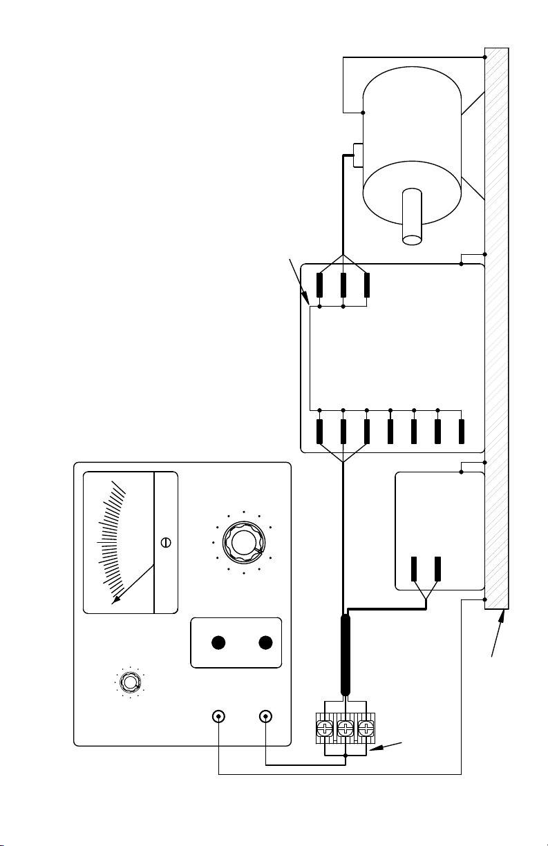
8 RECOMMENDED HIGH VOLTAGE DIELECTRIC WITHSTAND TESTING (HI-POT TESTING)
Testing agencies such as UL, CSA, VDE, etc., usually require that equipment undergo a hi-pot test. In order
to prevent catastrophic damage to the drive which has been installed in the equipment, the following
procedure is recommended. A typical hi-pot test setup is shown in Figure 33 on page 27. All drives have
been factory hi-pot tested in accordance with UL requirements.
WARNING! All equipment AC Line inputs must be disconnected from the AC power.
8.1 Connect all equipment AC power input lines together and connect them to the H.V. lead of the hipot tester. Connect the RETURN lead of the hi-pot tester to the frame on which the drive and other
auxiliary equipment are mounted.
8.2 The hi-pot tester must have an automatic ramp-up to the test voltage and an automatic rampdown to zero voltage.
Note: If the hi-pot tester does not have automatic ramping, then the hi-pot output must be manually
increased to the test voltage and then manually reduced to zero. This procedure must be followed for
each machine to be tested. A suggested hi-pot tester is Slaughter Model 2550.
CAUTION! Instantly applying the hi-pot voltage will cause irreversible damage to the drive, which
will void the warranty.
9 RECONDITIONING THE BUS CAPACITORS
If this drive has been in storage for over one year it is necessary to recondition the power supply bus
capacitors. To recondition the bus capacitors, apply the AC Line, with the drive in the Stop Mode, for a
minimum of one hour. Not following this procedure will cause the bus capacitors to fail.
8 kHz (Factory Setting)
12 kHz
Standard GFCI
Sensitive GFCI
Not Used
26
Machine Equipment or Frame
(Main Power Disconnected)
to AC Line Inputs
Connect Hi-Pot
High Voltage Dielectric Withstand Tester (Hi-Pot Tester)
(Main Power Disconnected)
Connect All Drive Terminals Together
Adjustable Frequency Drive
Frame
Motor Wires
Chassis
V
U
L1
W
P3
P2
L3
L2
P1
Signal Inputs
Figure 33 – Typical Hi-Pot Test Setup
3
Chassis
2
AC KILOVOLTS
1
VOLTAGETEST
MAX
L2
L1
Auxiliary Equipment
ZERO
0
RESET
10mA0mA
LEAKAGE
RETURN
H. V.
AC Line Input
27

10 DRIVE OPERATION
10.1 Start-Up Procedure – After the drive has been properly setup (jumpers and trimpots set to the
desired positions) and wiring completed, the start-up procedure can begin. If the AC power has
been properly brought to the drive, the power (PWR) LED will illuminate green. The status (ST) LED
will indicate drive status, as described in Section 12.2.
To start the drive, momentarily set the Start/Stop Switch to the “START” position. The motor will
begin to accelerate to the set speed.
WARNING! Using a jumper to eliminate the start/stop function will cause the motor to run at
the Main Speed Potentiometer setting when the AC Line is applied. See Section 10.2.
Note: If the motor rotates in the incorrect direction, it will be necessary to disconnect the AC Line, reverse
any two motor leads, and repeat the start-up procedure.
10.2 Restarting the Drive After a Fault has been Cleared
1,2
– The drive monitors ve faults:
Undervoltage, Overvoltage, Short Circuit at the motor (phase-to-phase), Overload and Phase Loss
Detection. See Section 12.2 for the Status (ST) LED indication. Also see Section 6.3 on page 23 for
Automatic Ride-Through or Manual Restart selection with Jumper J3.
To restart the drive after a fault has been cleared, use the Start/Stop Switch
2,3
.
If the Start/Stop Switch has been eliminated (bypassed), see Section 5.6 on page 21.4 The drive
can be restarted (after the fault has been cleared) by disconnecting the AC power, and all LEDs are
no longer illuminated, and then reconnecting the AC power.
Notes: 1. For an Overload Fault, be sure the fault has been cleared before restarting the drive. Check the
motor current with an AC RMS responding ammeter. Also, the CL setting may be set too low. See Section
13.7 on page 30. 2. For an Overvoltage Fault, if the drive is set for Automatic Ride-Through, the drive will
automatically restart when the AC Line voltage returns to below the specied Overvoltage Trip Point.
3. If the Forward-Stop-Reverse Switch has been installed, it can be used to restart the drive. 4. If the
Start/Stop Switch has been eliminated (bypassed), the AC Line must be used to restart the drive after an
Overload Fault has been cleared.
11 AC LINE FUSING
The drive does not contain line fuses. Most electrical codes require that each ungrounded conductor
contain circuit protection. Do not fuse neutral or ground connections. It is recommended to install
a fuse (Littelfuse 312/314, Buss ABC, or equivalent) or a circuit breaker in series with each ungrounded
conductor. Do not fuse motor leads. For the recommended fuse size, see Table 4 on page 14.
Wire the drive in accordance with the National Electrical Code requirements and other local codes that
may apply to the application.
12 DIAGNOSTIC LEDs
The drive contains two diagnostic LEDs mounted on the enclosure cover to display the drive’s
operational status.
12.1 Power On LED (PWR) – The “PWR” LED will illuminate green when the AC Line is applied
to the drive.
WARNING! Do not depend on the PWR LED as a guaranteed power o condition.
Be sure the main power switch or circuit breaker is in the “OFF” position before
servicing this drive.
12.2 Status LED (ST) – The “ST” LED is a tricolor LED which provides indication of a fault or abnormal
condition. The information provided can be used to diagnose an installation problem such as incorrect input voltage, overload condition, and drive output miswiring. It also provides a signal which
informs the user that all drive and microcontroller operating parameters are normal.
Table 7, summarizes the “ST” LED functions.
28

Table 7 – Drive Operating Condition and Status LED Indicator
Drive Operating Condition
Normal Operation Slow Flash Green
Overload (120% – 160% Full Load)
I2t (Drive Timed Out)
Short Circuit Slow Flash Red
Undervoltage
Overvoltage
Stop Steady Yellow
4
Stand-By
Input Phase Loss
Overtemperature Trip
Notes: 1. Slow Flash = 1 second on and 1 second o. Quick Flash = 0.25 second on and 0.25 second o. 2. When the Overload is removed, before
2
the I
t times out and trips the drive, the “ST” LED will ash green. 3. When the Undervoltage or Overvoltage condition is corrected, the “ST” LED
5
6
will ash Red / Yellow / Green. 4. Only if the Forward-Stop-Reverse Switch is installed. 5. Model KBAC-29, with three-Phase AC Line input, and
Models KBAC-45, 48. Rapid Flash = 4 mSec on and 6 mSec o. 6. KBAC-217 Series and KBAC-416 Series only.
13 TRIMPOT ADJUSTMENTS
The drive contains trimpots which are factory set for most applications. See Figure 2 on page 10 for the
location of the trimpots and their approximate factory calibrated positions. Some applications may
require readjustment of the trimpots in order to tailor the drive for a specic requirement. The trimpots
may be readjusted as described below.
WARNING! If possible, do not adjust trimpots with the main power applied. If adjust-
ments are made with the main power applied, an insulated adjustment tool must be
used and safety glasses must be worn. High voltage exists in this drive. Fire and/or electrocution
can result if caution is not exercised. The Safety Warning on page 5 must be read and understood
before proceeding.
13.1 Minimum Speed (MIN) – Sets the minimum speed of the motor. The MIN Trimpot is factory set to
0% of frequency setting. For a higher minimum speed setting, rotate the MIN Trimpot clockwise.
See Figure 34 on page 30.
13.2 Maximum Speed (MAX) – Sets the maximum speed of the motor. The MAX Trimpot is factory set
to 100% of frequency setting. For a lower maximum speed setting, rotate the MAX Trimpot counterclockwise. For a higher maximum speed setting, rotate the MAX Trimpot clockwise. See Figure 35
on page 30.
13.3 Acceleration (ACCEL) – Sets the amount of time for the motor to accelerate from zero speed to full
speed. The ACCEL Trimpot is factory set to 1.5 seconds. For a longer acceleration time, rotate the
ACCEL Trimpot clockwise. For more rapid acceleration, rotate the ACCEL Trimpot counterclockwise.
See Figure 36 on page 30.
Note: Rapid acceleration settings may cause the current limit circuit to activate, which will extend the
acceleration time.
13.4 Deceleration (DEC/I) – Sets the amount of time for the motor to decelerate from full speed to zero
speed. The DEC/I Trimpot is factory set to 1.5 seconds. For longer deceleration time, rotate the DEC/I
Trimpot clockwise. For more rapid deceleration, rotate the DEC/I Trimpot counterclockwise. See
Figure 37 on page 30.
Application Note – On applications with high inertial loads, the deceleration time may automati-
cally increase. This will slow down the decrease speed to prevent the bus voltage from rising
to the Overvoltage Trip point. This function is called Regeneration Protection. It is recommended
that for very high inertial loads that both the ACCEL and DEC/I Trimpots be set to greater
than 10 seconds.
13.5 DC Injection Brake (DEC/I) – The drive is factory set for Regenerative Braking (Jumper J7 set to the
“RG” position). When the drive is set for DC Injection Brake (Jumper J7 set to the “INJ” position), the
DEC/I Trimpot is used to set the DC Injection Brake voltage and time. See Figure 38 on page 30. Also
see Section 6.6 on page 25.
1
and LED Color
Flash Rate
2
Steady Red
Quick Flash Red
Quick Flash Red / Yellow
Slow Flash Red / Yellow
Slow Flash Yellow
Rapid Flash Yellow
Slow / Quick Flash Red
2
3
3
1
29

The DC Injection Brake voltage and time range is 10% of full drive output voltage for 3 seconds with
the trimpot fully clockwise and 25% of full drive output voltage for 1 second with the trimpot fully
counterclockwise. Models KBAC-24D, 27D, 29, KBAC-217 Series are factory set for 49 Volts for 1.2
seconds and Models KBAC-45, 48, KBAC-416 Series are factory set for 98 Volts for 1.2 seconds.
Adjust the trimpot so that the load stops within the required time.
Figure 34 – Minimum Speed
Trimpot Range
30
15 35
0
(Shown Factory Set to 0% Frequency Setting)
40
MIN
Figure 37 – Deceleration
Trimpot Range
10
3
1.5
0.3
(Shown Factory Set to 1.5 Seconds)
13.6 Slip Compensation (COMP) – Sets the amount of Volts/Hz to
maintain set motor speed under varying loads. The COMP Trimpot
is factory set to 1.5 Volts/Hz, which provides excellent speed regulation for most motors. To increase the slip compensation, rotate
the COMP Trimpot clockwise. To decrease the slip compensation,
rotate the COMP Trimpot counterclockwise. See Figure 39.
The slip compensation may be adjusted as follows:
1. Wire an AC RMS ammeter in series with one motor phase.
2. Run the motor and set the unloaded speed to approximately
50% (900 RPM on 4-pole 1500/1725 RPM motors).
3. Using a tachometer, record the unloaded speed.
4. Load the motor to the nameplate rated current (AC Amps).
5. Adjust the COMP Trimpot until the loaded RPM is equal to the
unloaded RPM.
6. The motor is now compensated to provide constant speed
under varying loads.
13.7 Motor Overload (I2t) With RMS Current Limit (CL)* – Sets the
current limit (overload), which limits the maximum current to the
motor, which prevents motor burnout and eliminates nuisance trips. The CL Trimpot is factory set
to 160% of the drive rated current. To increase the current limit, rotate the CL Trimpot clockwise.
To decrease the current limit, rotate the CL Trimpot counterclockwise. See Figure 40. Also see Figure
41 on page 31.
*UL approved as an electronic overload protector for motors.
17
20
DEC/I
Figure 35 – Maximum Speed
Trimpot Range
80
75 90
100
70
(Shown Factory Set to 100% Frequency Setting)
110
MAX
Figure 36 – Acceleration
Trimpot Range
10
3
1.5
0.3
ACCEL
(Shown Factory Set to 1.5 Seconds)
Figure 38 – DC Injection Brake Trimpot Range
Models KBAC-24D, 27D, 29, KBAC-217 Series Models KBAC-45, 48, KBAC-416 Series
40, 2.0
43, 1.5
49, 1.2
57, 1.0
(Shown Factory Set to 49 Volts for 1.2 Seconds)
31, 2.5
23, 3.0
DEC/I
114, 1.0
(Shown Factory Set to 98 Volts for 1.2 Seconds)
80, 2.0
86, 1.5
98, 1.2
DEC/I
Figure 39– Slip Compensation
Trimpot Range
1.5
0.8
0
COMP
(Shown Factory Set to 1.5 Volts/Hz)
Figure 40 – Current Limit
Trimpot Range
120
80 160
40 200
(Shown Factory Set to 160% Full Load)
CL
17
20
62, 2.5
46, 3.0
2.3
3
30
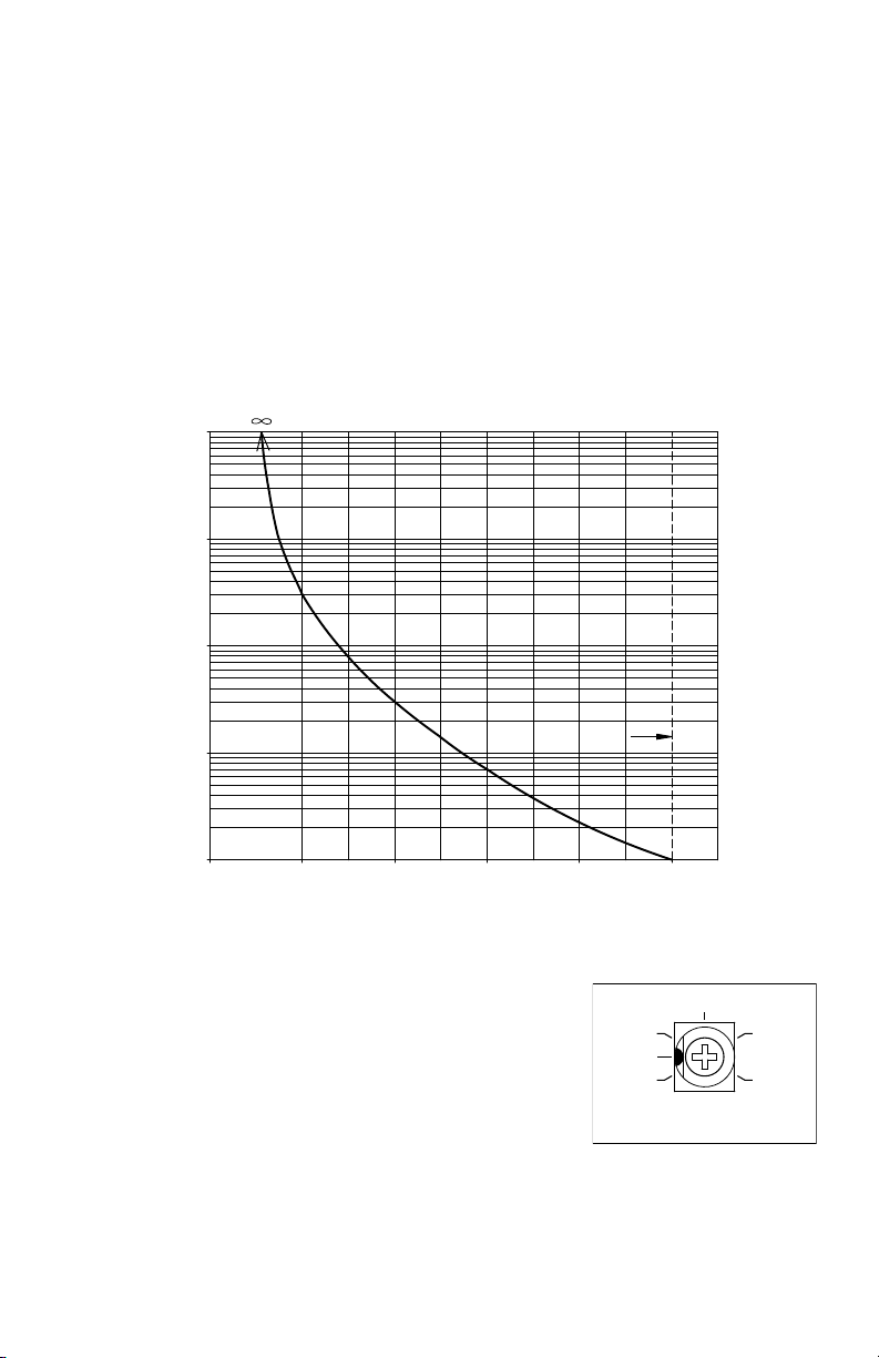
CAUTION! Adjusting the current limit above 160% of the motor nameplate rating can cause
Trip Time (Minutes)
Motor Current (%)
overheating of the motor. Consult the motor manufacturer. Do not leave the motor in a locked
rotor condition for more than a few seconds since motor damage may occur.
In order to ensure that the motor is properly protected with the I2t feature, it is required that
the CL Trimpot be set for 160% of the motor nameplate rated current, as described below.
Note: This adjustment must be made within 6 seconds or the I2t Trip will occur.
The current limit may be adjusted as follows:
1. Connect an AC RMS ammeter in series with one motor phase.
2. Set the CL Trimpot fully counterclockwise.
3. Adjust the speed setting to 30%.
4. Lock the motor shaft and adjust the CL Trimpot to 160% of the motor nameplate rated current.
Figure 41 – I2t Trip Time vs. Motor Current
1000
100
10
140110 120 130
CL (Factory Setting)
160150
Figure 42 – Boost
Trimpot Range
15
8
5
0
BOOST
(Shown Factory Set to 5 Volts/Hz)
22
30
1
0.1
13.8 Boost (BOOST) – The drive is factory set for Fixed Boost
(Jumper J6 set to the “FIX” position). When the drive is set for
Adjustable Boost (Jumper J6 set to the “ADJ” position), the BOOST
Trimpot can be used to adjust the amount of boost voltage to the
motor. See Figure 42. Also see Section 6.5 on page 24.
Application Note – The Boost function operates over a frequency
range of 0 – 15 Hz. If the frequency range required is above 15 Hz,
Boost adjustment is not necessary.
WARNING! To avoid motor winding overheating and failure,
do not overboost the motor.
Note: An unloaded motor with excessive boost will draw more current than a partially loaded motor.
31
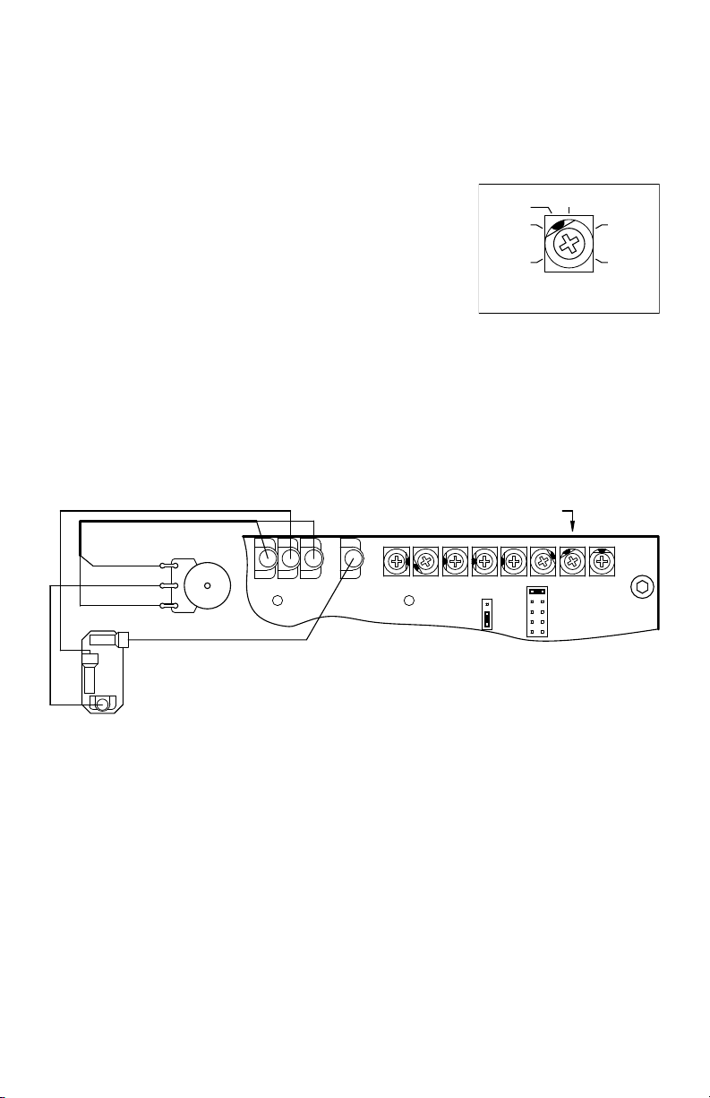
The boost voltage may be adjusted as follows:
Jog Trimpot
1. Wire an AC RMS ammeter in series with one motor phase.
2. Run the motor unloaded at approximately 4 Hz (or 120 RPM).
3. Increase the boost until the ammeter reaches the motor nameplate rated current (Amps AC).
4. Using the Main Speed Potentiometer, slowly adjust the mo-
tor speed over a 1 – 15 Hz (0 – 450 RPM) range. If the motor
Figure 43 – Jog
Trimpot Range
current exceeds the nameplate rating, decrease the boost
setting.
13.9 Jog (JOG) – The Jog feature requires the installation of a
Run-Stop-Jog Switch. The switch must be wired according
to Figure 44. The JOG Trimpot range is shown in Figure 43.
The orange Main Speed Potentiometer wire (wiper) which
connects to Terminal “P2” on the drive must be removed and
35
25
0
(Shown Factory Set to 35% Frequency Setting)
installed on Terminal “RUN” on the switch. The “JOG” Terminal on
the drive connects to “JOG” on the switch. Terminal “P2” on the drive connects to the center (common) terminal on the switch.
When the switch is in the “JOG” position, the JOG Trimpot
is used to set the “jog” speed. When the switch is in the “RUN”
position, the Main Speed Potentiometer is used for speed setting.
The Run-Stop-Jog Switch is available as an optional accessory. See Table 2 on page 9.
Figure 44 – Run-Stop-Jog Switch Connection (SPDT – Center O)*
Main Speed
Violet (High) (P3)
Orange (Wiper)
White (Low) (P1)
(P2)
(Wiper)
Potentiometer
(JOG)
Run-Stop-Jog Switch
(SPDT - Center O)
P1
P3 P2
*Layout may vary.
MAX MIN
JOG
MA
J2
J3
50
75
100
JOG
CL JOG COMPBOOSTACCEL DECEL
A
B
C
D
E
32

APPENDIX A – Optional SIAC-PS Signal Isolator with Power Supply
TB1A
8
6
7
5
4
3
2
1
See SIAC-PS Installation Instructions for details and connections.
Description
The SIAC-PS Signal Isolator with Power Supply provides an isolated interface between non-isolated signal sources
and the drive. It is used to isolate, amplify, and condition DC voltage and current signals from any source
(tach-generators, transducers, PLCs, and potentiometers). It provides an isolated input to control motor direction
and an isolated 5 Volt DC power supply for potentiometer operation. In addition, this updated model contains an
isolated 24 Volt DC power supply for transducers or auxiliary equipment. All input connections and power supplies
are isolated from the AC Line and motor wiring. It installs easily into the drive with a snap-in mounting base and is
wired with a connector.
Main features include voltage or current signal inputs. Other features include a power on LED, barrier terminal blocks
to facilitate wiring, multi-turn trimpots (MAX1, OFFSET), and a jumper for voltage or current signal input selection.
An optional accessory for use with the SIAC-PS is the Auto/Manual Switch to select a signal input from either the
SIAC-PS or the Main Speed Potentiometer of the drive.
Table 1 – General Performance Specications
Parameter Specication Factory Setting
Maximum Speed Trimpot (MAX1) Input Voltage Range (Volts DC) 0 to 2.5 thru 0 to 25 0 to 5
Offset Trimpot (OFFSET) Range (% of MAX1 Trimpot Setting) 0 – ±50 0
Input Current Range (milliamps DC) 4 – 20 —
Forward and Reverse Input Switch Types Dry Contact or Open Collector —
5 Volt DC Power Supply Maximum Load Current Rating (milliamps DC) 1 —
24 Volt DC Power Supply Maximum Load Current Rating (milliamps DC) 50 —
Potentiometer Operation (kΩ) 5 —
Input/Output Linearity (%) 0.1 —
Thermal Drift (millivolts per °C) 0.4 —
Operating Temperature Range (°C / °F) 0 – 40 / 32 – 104 —
Operating Humidity Range (% Relative, Non-Condensing) 0 – 95 —
Storage Temperature (°C / °F) -25 – +85 / -13 – +185 —
Figure 1 – SIAC-PS Layout and Descriptions*
+5V -5V OV FWD REV SIG1 COM1
TB1B
PWR
OFFSET
MAX1
24V COM4
TB2
J1
CUR V OLT
CON1
*Layout may vary.
No. Description
J1: Sets the drive for operation with a voltage or current signal input.
1
TB2: Isolated 24 Volt DC power supply. Used for powering transducers or auxiliary equipment.
2
MAX1: Maximum signal input adjustment trimpot.
3
OFFSET: Signal Oset adjustment trimpot.
4
TB1B: Potentiometer or Signal Input and Direction Switch connections.
5
TB1A: Isolated 5 Volt DC power supply. Can be used for Main Speed Potentiometer operation.
6
PWR: Power On LED.
7
CON1: Used for the Ribbon Cable to connect the SIAC-PS to the drive.
8
33

– Notes –
34

– Notes –
35
 Loading...