

Page 1
Installation & Operation Manual
A Complete Line of Motor Drives
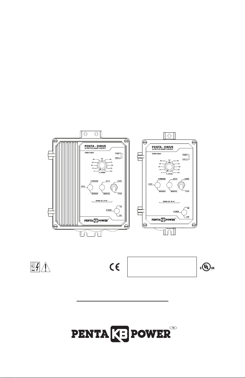
KBAC SERIES
Adjustable Frequency Drives for 3-Phase AC Motors
NEMA-4X / IP-65
Variable Speed/ Soft-Start AC Motor Drive
with Electronic Motor Overload Protection for Inverter Duty Motors*
Washdown and Watertight for Indodor and Outdoor Use
Rated for 208 – 230 and 400/460 Volt 50 & 60 Hz
3-Phase & PSC** AC Induction Motors from 1 HP thru 5 HP
Operates from 115, 208/230 Volt and 400/460 Volt 50/60 Hz AC Line**
This Manual Covers Models KBAC-24D, 27D, 29, 45, 48
See Safety Warning,
on page 5.
The information contained in this manual is intended to be accurate. However, the manufacturer retains
the right to make changes in design which may not be included herein.
*UL approved as an electronic overload protector for motors. **Do not use this drive with GFCIs. Special
software is available – contact our Sales Department. ***Installation of a CE approved RFI filter is required.
Note: The drive is factory set for
***
60 Hz motors. For 50 Hz motors,
see Section 6.1, on pages 16 – 17.
© 2006 KB Electronics, Inc.
(see back cover)
Page 2

BLE OF CONTENTS
ection Page
S
Quick-Start Instructions . . . . . . . . . . . . . . . . . . . . . . . . . . . . . . . . . . . . . . . . . . . . . . . . . . . . . . . . . . . . . . . . 4
1
TA
2 Safety Warning . . . . . . . . . . . . . . . . . . . . . . . . . . . . . . . . . . . . . . . . . . . . . . . . . . . . . . . . . . . . . . . . . . . . . . 5
3 Introduction . . . . . . . . . . . . . . . . . . . . . . . . . . . . . . . . . . . . . . . . . . . . . . . . . . . . . . . . . . . . . . . . . . . . . . . . . 6
4 Important Application Information . . . . . . . . . . . . . . . . . . . . . . . . . . . . . . . . . . . . . . . . . . . . . . . . . . . . . . . 12
5 Wiring Instructions . . . . . . . . . . . . . . . . . . . . . . . . . . . . . . . . . . . . . . . . . . . . . . . . . . . . . . . . . . . . . . . . . . . 13
6 Setting Selectable Jumpers . . . . . . . . . . . . . . . . . . . . . . . . . . . . . . . . . . . . . . . . . . . . . . . . . . . . . . . . . . . . 16
7 Mounting Instructions . . . . . . . . . . . . . . . . . . . . . . . . . . . . . . . . . . . . . . . . . . . . . . . . . . . . . . . . . . . . . . . . 19
8 Recommended High Voltage Dielectric Withstand Testing (Hi-Pot Testing) . . . . . . . . . . . . . . . . . . . . . . . . . 19
Drive Operation . . . . . . . . . . . . . . . . . . . . . . . . . . . . . . . . . . . . . . . . . . . . . . . . . . . . . . . . . . . . . . . . . . . . . 21
9
10 AC Line Fusing . . . . . . . . . . . . . . . . . . . . . . . . . . . . . . . . . . . . . . . . . . . . . . . . . . . . . . . . . . . . . . . . . . . . . 21
1 Diagnostic LEDs . . . . . . . . . . . . . . . . . . . . . . . . . . . . . . . . . . . . . . . . . . . . . . . . . . . . . . . . . . . . . . . . . . . . 21
1
12 Trimpot Adjustments . . . . . . . . . . . . . . . . . . . . . . . . . . . . . . . . . . . . . . . . . . . . . . . . . . . . . . . . . . . . . . . . . 22
Limited Warranty . . . . . . . . . . . . . . . . . . . . . . . . . . . . . . . . . . . . . . . . . . . . . . . . . . . . . . . . . . . . . . . . . . . . . . . 28
Tables Page
1 Jumper Selectable Features . . . . . . . . . . . . . . . . . . . . . . . . . . . . . . . . . . . . . . . . . . . . . . . . . . . . . . . . . . . . 8
2 Optional Accessories . . . . . . . . . . . . . . . . . . . . . . . . . . . . . . . . . . . . . . . . . . . . . . . . . . . . . . . . . . . . . . . . . . 8
3 General Performance Specifications . . . . . . . . . . . . . . . . . . . . . . . . . . . . . . . . . . . . . . . . . . . . . . . . . . . . . 10
4 Electrical Ratings . . . . . . . . . . . . . . . . . . . . . . . . . . . . . . . . . . . . . . . . . . . . . . . . . . . . . . . . . . . . . . . . . . . . 10
5 Terminal Block Wiring Information . . . . . . . . . . . . . . . . . . . . . . . . . . . . . . . . . . . . . . . . . . . . . . . . . . . . . . . 13
6 Drive Operating Condition and Run/Fault Relay Contact Status . . . . . . . . . . . . . . . . . . . . . . . . . . . . . . . . . 16
7 Drive Operating Condition and Status LED Indicator . . . . . . . . . . . . . . . . . . . . . . . . . . . . . . . . . . . . . . . . . 22
Figures Page
1 Quick-Start Connection Diagram . . . . . . . . . . . . . . . . . . . . . . . . . . . . . . . . . . . . . . . . . . . . . . . . . . . . . . . . . 4
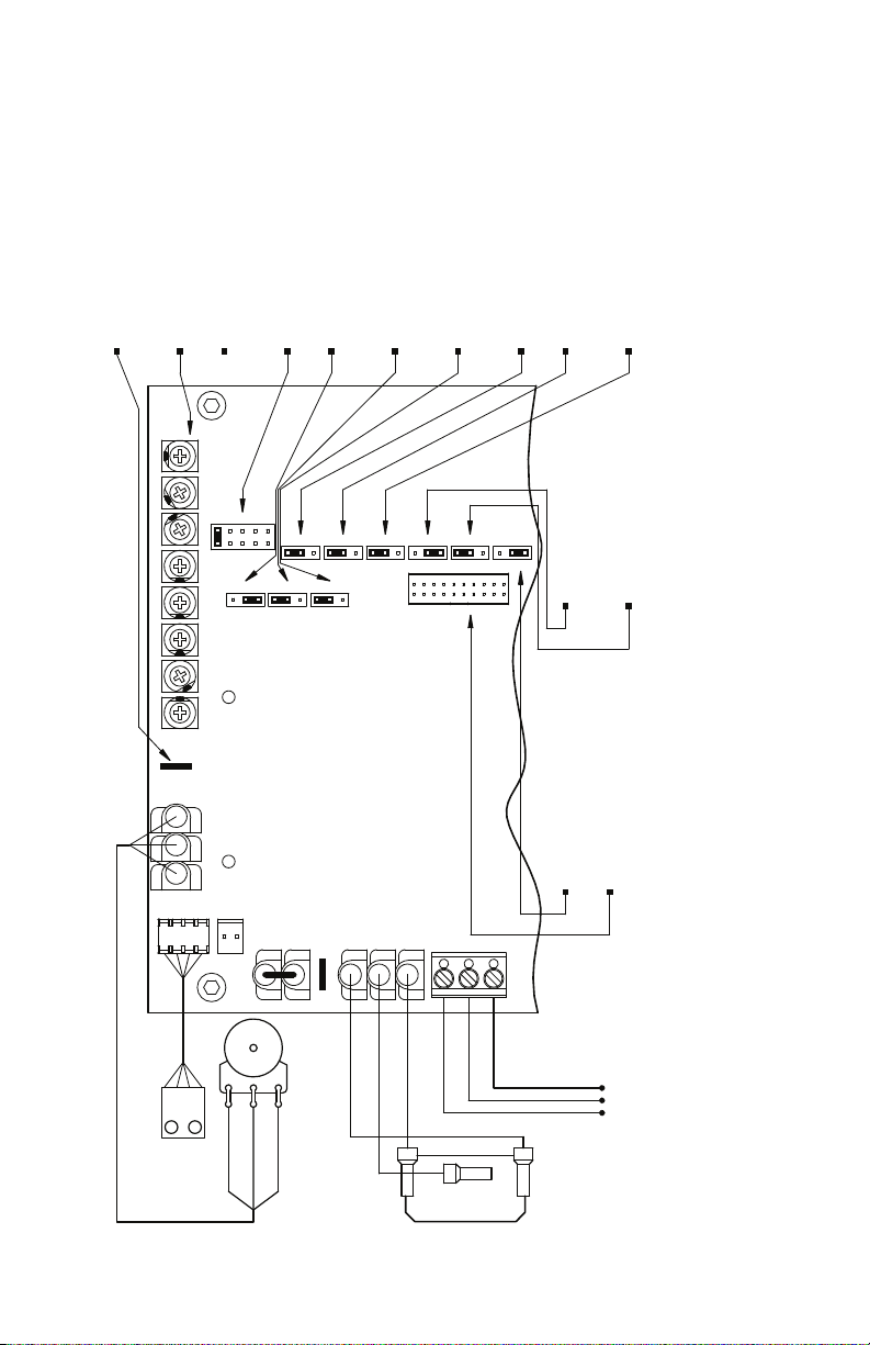
2 Control Layout . . . . . . . . . . . . . . . . . . . . . . . . . . . . . . . . . . . . . . . . . . . . . . . . . . . . . . . . . . . . . . . . . . . . . . . 9
3 Model KBAC-24D Mechanical Specifications . . . . . . . . . . . . . . . . . . . . . . . . . . . . . . . . . . . . . . . . . . . . . . . 11
4 Models KBAC-27D, 29, 45, 48 Mechanical Specifications . . . . . . . . . . . . . . . . . . . . . . . . . . . . . . . . . . . . . 11
5 Maximum Allowed Motor Torque vs. Speed . . . . . . . . . . . . . . . . . . . . . . . . . . . . . . . . . . . . . . . . . . . . . . . .12
6 Open Ventilated Motor with External Fan Cooling . . . . . . . . . . . . . . . . . . . . . . . . . . . . . . . . . . . . . . . . . . . 12
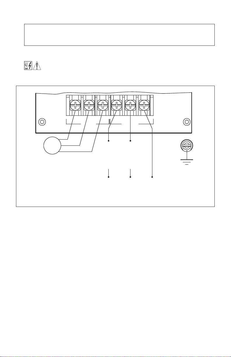
7 Models KBAC-24D, 27D AC Line Input, Motor, and Ground Connections . . . . . . . . . . . . . . . . . . . . . . . . . 13
8 Models KBAC-29, 45, 48 AC Line Input, Motor, and Ground Connections . . . . . . . . . . . . . . . . . . . . . . . . 14
9 Remote Main Speed Potentiometer Connection . . . . . . . . . . . . . . . . . . . . . . . . . . . . . . . . . . . . . . . . . . . . 14
10 Remote Start/Stop Switch Connection with Normally Open Stop Contact . . . . . . . . . . . . . . . . . . . . . . . . 15
11 Remote Start/Stop Switch Connection with Normally Closed Stop Contact . . . . . . . . . . . . . . . . . . . . . . . 15
12 Start/Stop Function Eliminated . . . . . . . . . . . . . . . . . . . . . . . . . . . . . . . . . . . . . . . . . . . . . . . . . . . . . . . . . 15
13 Voltage Following Connections . . . . . . . . . . . . . . . . . . . . . . . . . . . . . . . . . . . . . . . . . . . . . . . . . . . . . . . . . 15
14 Enable Circuit Connection . . . . . . . . . . . . . . . . . . . . . . . . . . . . . . . . . . . . . . . . . . . . . . . . . . . . . . . . . . . . . 16
15 Run/Fault Relay Output Contacts Connection . . . . . . . . . . . . . . . . . . . . . . . . . . . . . . . . . . . . . . . . . . . . . . 16
16 Models KBAC-24D, 27D AC Line Input Voltage Selection (Jumper J1) . . . . . . . . . . . . . . . . . . . . . . . . . . . 16
17 Removing Jumper J1 on Models KBAC-24D, 27D . . . . . . . . . . . . . . . . . . . . . . . . . . . . . . . . . . . . . . . . . . 17
18 Motor Horsepower Selection (Jumper J2) . . . . . . . . . . . . . . . . . . . . . . . . . . . . . . . . . . . . . . . . . . . . . . . . . 17
19 Automatic Ride-Through or Manual Restart Selection (Jumper J3) . . . . . . . . . . . . . . . . . . . . . . . . . . . . . . 17
20 60 Hz and 50 Hz Motor Selection (Jumpers J4 and J5) . . . . . . . . . . . . . . . . . . . . . . . . . . . . . . . . . . . . . . 17
21 Available Torque vs. Output Frequency . . . . . . . . . . . . . . . . . . . . . . . . . . . . . . . . . . . . . . . . . . . . . . . . . . . 18
120 Hz and 100 Hz Drive Output Fr
22
equency Selection
. . . . . . . . . . . . . . . . . . . . . . . . . . . . . . . . . . . . . . . 18
23 Fixed or Adjustable Boost Selection (Jumper J6) . . . . . . . . . . . . . . . . . . . . . . . . . . . . . . . . . . . . . . . . . . . . 18
24 Regenerative or DC Injection Braking Selection (Jumper J7) . . . . . . . . . . . . . . . . . . . . . . . . . . . . . . . . . . . 18
25 “Run” or “Fault” Output Relay Operation Selection (Jumper J8) . . . . . . . . . . . . . . . . . . . . . . . . . . . . . . . . . 19
26 Normally Open or Closed Stop Contact Selection (Jumper J9) . . . . . . . . . . . . . . . . . . . . . . . . . . . . . . . . . 19
27 Constant or Variable Torque Selection (Jumper J10) . . . . . . . . . . . . . . . . . . . . . . . . . . . . . . . . . . . . . . . . . 19
2
t Overload Selection (Jumper J11) . . . . . . . . . . . . . . . . . . . . . . . . . . . . . . . . . . . . . . . . . . . . . . . . . . . . . 19
28 I
29 Typical Hi-Pot Test Setup . . . . . . . . . . . . . . . . . . . . . . . . . . . . . . . . . . . . . . . . . . . . . . . . . . . . . . . . . . . . . . 20
ii
Page 3

0 Minimum Speed Trimpot (MIN) Range . . . . . . . . . . . . . . . . . . . . . . . . . . . . . . . . . . . . . . . . . . . . . . . . . . . . 22
3
1 Maximum Speed Trimpot (MAX) Range . . . . . . . . . . . . . . . . . . . . . . . . . . . . . . . . . . . . . . . . . . . . . . . . . . . 22
3
2 Acceleration Trimpot (ACCEL) Range . . . . . . . . . . . . . . . . . . . . . . . . . . . . . . . . . . . . . . . . . . . . . . . . . . . . . 22
3
33 Deceleration Trimpot (DECEL) Range . . . . . . . . . . . . . . . . . . . . . . . . . . . . . . . . . . . . . . . . . . . . . . . . . . . . . 23
34 DC Injection Brake Trimpot (DECEL) Range . . . . . . . . . . . . . . . . . . . . . . . . . . . . . . . . . . . . . . . . . . . . . . . . 23
35 Slip Compensation Trimpot (COMP) Range . . . . . . . . . . . . . . . . . . . . . . . . . . . . . . . . . . . . . . . . . . . . . . . . 23
36 Current Limit Trimpot (CL) Range . . . . . . . . . . . . . . . . . . . . . . . . . . . . . . . . . . . . . . . . . . . . . . . . . . . . . . . . 23
2
37 I
t Trip Time vs. Motor Current . . . . . . . . . . . . . . . . . . . . . . . . . . . . . . . . . . . . . . . . . . . . . . . . . . . . . . . . . 24
38 Boost Trimpot (BOOST) Range . . . . . . . . . . . . . . . . . . . . . . . . . . . . . . . . . . . . . . . . . . . . . . . . . . . . . . . . . 25
39 Jog Trimpot (JOG) Range . . . . . . . . . . . . . . . . . . . . . . . . . . . . . . . . . . . . . . . . . . . . . . . . . . . . . . . . . . . . . 25
Items Included In this Package:
Adjustable Frequency Drive, Installation and Operation Manual, Trimpot Adjustment Tool, CE Approved Product
Information Card, Warranty Registration Card.
iii
Page 4
1 QUICK-START INSTRUCTIONS
see Section 5.2, on page 14.
Ground (Earth):
(Ter minals L1, L2, L3)
see Section 5.1, on pages 13 – 14.
(Models KBAC-29, 45, 48):
50/60 Hz, AC Line Input
208/230, 400/460 Volt, 3-Phase,
(Ter minals L1, L2)
see Section 5.1, on pages 13 – 14.
(Models KBAC-24D, 27D, 29):
50/60 Hz, AC Line Input
208/230 Volt, Single Phase,
3-Phase
see Section 5.3, on page 14.
AC Induction Motor:
AC LINEMOTOR
Motor
TB1
L2
L1V WUL3
Important – You must read these simplified instructions before proceeding. These instructions are to be
used as a reference only and are not intended to replace the details provided herein. You must read the
Safety Warning on, page 5, before proceeding.
See Figure 1. Also see Section 4 - Important Application Information, on page 12.
WARNING! Disconnect main power before making connections to the drive.
FIGURE 1 – QUICK-START CONNECTION DIAGRAM*
*Layout of Model KBAC-24D varies slightly.
1.1 AC LINE INPUT CONNECTION – Wire the AC line input to Terminal Block TB1. See Section 5.1, on
pages 13 – 14.
Application Note: Do not wire this drive to a GFCI. If operation with a GFCI is required, contact
our Sales Department.
Note: The rated AC line voltage of the drive must match the actual AC line input voltage. On Models
KBAC-24D, 27D, the setting of Jumper J1 must match the AC line input voltage.
Models KBAC-24D, 27D: Designed to accept single-phase (Terminals “L1”, “L2”) AC line input only.
Rated for 208/230 Volt AC line input with Jumper J1 set to the “230V” position (factory setting). Rated
for 115 Volt AC line input with Jumper J1 set to the “115V” position. See Figure 7, on page 13.
4
Note: Model KBAC-27D is rated for 11⁄2 HP maximum with 115 Volt AC line input and 2 HP maximum
with 208/230 V
Model KBAC-29: Designed to accept single-phase (T
“L2”, “L3”) AC line input. Rated for 208/230 Volt AC line input only. See Figure 8, on page 14.
Note: Rated for 2 HP maximum with single-phase AC line input and 3 HP maximum with 3-phase AC
line input.
olt AC line input.
erminals “L1”, “L2”) or 3-phase (T
erminals “L1”,
Page 5

odels KBAC-45, 48: Designed to accept 3-phase (Terminals “L1”, “L2”, “L3”) AC line input only.
M
ated for 400/460 Volt AC line input only. See Figure 8, on page 14.
R
.2 AC LINE FUSING –It is recommended that a fuse(s) or circuit breaker be installed in the AC line.
1
use each conductor that is not at ground potential. For the recommended fuse size, see Table 4, on
F
age 10. Also see Section 10, on page 21.
p
.3 GROUND CONNECTION –Connect the ground wire (earth) to the ground screw, as shown in Figure
1
7, on page 13, and Figure 8, on page 14. See Section 5.2, on page 14.
1.4 MOTOR CONNECTION – Wire the motor to Terminal Block TB1 Terminals “U”, “V”, “W”, as shown in
Figure 7, on page 13, and Figure 8, on page 14. (Special reactors may be required for cable lengths
ver 100 ft. (30 m) – consult our Sales Department.) See Section 5.3, on page 14.
o
.5 60 Hz and 50 Hz MOTOR OPERATION –The drive is factory set for 60 Hz motor operation (Jumper
1
J5 set to the “60Hz” position). For 50 Hz motor operation, set Jumper J5 to the “50Hz” position. See
Section 6.4, on page 17.
1.6 START/STOP SWITCH – The drive is supplied with a prewired Start/Stop Switch to electronically
“start” and “stop” the drive, as described in Section 5.5, on pages 14 – 15. This switch must be used
to “start” the drive each time the AC line is applied to the drive or to “restart” the drive. Also see
Section 6.8, on page 18.
1.7 JUMPER SETTINGS – All jumpers have been factory set for most applications, as shown in Figure 2,
on page 9. Some applications require setting of the jumpers in order to tailor the drive for a specific
requirement. See Section 6, on pages 16 – 18.
1.8 TRIMPOT SETTINGS – All trimpots have been factory set for most applications, as shown in Figure
2, on page 9. Some applications require adjustment of the trimpots in order to tailor the drive for a
specific requirement. See Section 12, on pages 22 – 25.
1.9 DIAGNOSTIC LEDs – After power has been applied, observe the LEDs to verify proper drive opera-
tion, as described in Section 11, on pages 21 – 22.
2 SAFETY WARNING
Definition of Safety Warning Symbols
Electrical Hazard Warning Symbol – Failure to observe this warning could result in electrical
shock or electrocution.
Operational Hazard Warning Symbol – Failure to observe this warning could result in serious
injury or death.
This product should be installed and serviced by a qualified technician, electrician, or
electrical maintenance person familiar with its operation and the hazards involved. Proper
installation, which includes wiring, fusing or other current protection, and grounding can reduce the
chance of electrical shocks, and/or fires, in this product or products used with this product, such as
electric motors, switches, coils, solenoids, and/or relays. Do not use this drive in an explosion-proof
application. Eye pr
with drive under power. This product is constructed of materials (plastics, metals, carbon, silicon, etc.)
which may be a potential hazard. Proper shielding, grounding, and filtering of this product can reduce
the emission of radio frequency interference (RFI) which may adversely affect sensitive electronic
equipment. It is the r
Safety Warning to the ultimate end user of this product. Be sure to follow all instructions carefully.
Fire and/or electrocution can result due to improper use of this product. (SW 1/2006)
otection must be wor
esponsibility of the equipment manufacturer and individual installer to supply this
n and insulated adjustment tools must be used when working
5
Page 6

his product complies with all CE directives pertinent at the time of manufacture. Contact our Sales
T
epartment for Declaration of Conformity. Installation of a CE approved RFI filter is required. See RFI
D
ilters & Chokes Selection Guide D-321 (Part No. A42027) for selection of filters to meet the Industrial or
F
esidential Standard. Additional shielded cable and/or AC line cables may be required along with a signal
R
solator (SIAC (Part No. 9488)).
i
3 INTRODUCTION
hank you for purchasing the KBAC Adjustable Frequency Drive. KB Electronics, Inc. is committed to pro-
T
iding total customer satisfaction by producing quality products that are easy to install and operate. The
v
BAC is manufactured with surface mount components incorporating advanced circuitry and technology.
K
The drives are variable speed controls housed in a rugged NEMA-4X / IP-65 washdown and watertight
die-cast aluminum enclosure. They are designed to operate 208 – 230 and 400/460 Volt 50 & 60 Hz
3-phase AC induction motors from 1 HP thru 5 HP. The sine wave coded Pulse Width Modulated (PWM) output operates at a carrier frequency of 16 kHz which provides high motor efficiency and low noise. Adjustable
Linear Acceleration and Deceleration are provided, making the drive suitable for soft-start applications.
Due to its user-friendly design, the KBAC AC drive is easy to install and operate. Tailoring to specific applications is accomplished with selectable jumpers and trimpots, which eliminate the computer-like programming
required on other drives. However, for most applications no adjustments are necessary. For more advanced
programming, PC based Drive-Link™ software is available.
2
Main features include adjustable RMS Current Limit and I
t Motor Overload Protection.* In addition,
Adjustable Slip Compensation with Static Auto-Tune and Boost provides high torque and excellent load regulation over a wide speed range. Power Start™ delivers over 200% motor torque to ensure start-up of high
frictional loads. Electronic Inrush Current Limit (EICL™) eliminates harmful AC line inrush current. A Run/Fault
Relay is provided, which can be used to turn on or off equipment or to signal a warning if the drive is put
into the Stop Mode or if a fault has occurred. The drive is suitable for machine or variable torque (HVAC)
applications. Also, a jumper is provided for selection of Regenerative or DC Injection Braking.
Standard front panel features include Diagnostic LEDs for “Power On” and “Drive Status”, a Start/Stop
Switch, and a Main Speed Potentiometer. Other features include a Barrier Terminal Block to facilitate wiring
of the AC line and motor, adjustable trimpots (MIN, MAX, ACCEL, DECEL, COMP, CL, JOG, BOOST), customer selectable jumpers (Line Voltage (dual voltage models only), Motor Horsepower, Automatic RideThrough / Manual Start, Motor Frequency, Frequency Multiplier, Fixed/Adjustable Boost,
Regenerative/Injection Braking, “Run” or “Fault” Output Relay Operation, NO/NC Stop Contact,
Constant/Variable Torque, I
2
t Overload Selection).
Optional accessories include: Forward-Stop-Reverse Switch, On/Off AC Line Switch, Run-Stop-Jog Switch,
Signal Isolator, Auto/Manual Switch, Class ”A” AC Line Filter, Multi-Speed Board, Programming Kit, Modbus
Communication Module, and Liquidtight Fittings. A connector is provided for easy installation of accessories.
Custom software: all models can be factory programmed for applications which require special timing, PLC
functions, and GFCI operation – contact our Sales Department.
*UL approved as an electronic overload protector for motors.
3.1 STANDARD FEATURES
• Industrial Duty Die-Cast Aluminum Case with Hinged Cover –
approved white finish.
• Simple to Operate – Does not require programming. Uses trimpots and jumpers, which are factory
set for most applications.
Motor HP Selection Jumper –
•
recalibration.
Diagnostic LEDs –
•
• Run/Fault Relay Output Contacts – Can be used to turn on or off equipment or to signal a
6
warning if the drive is put into the Stop Mode or a fault has occurred.
Allows the drive to be used on a wide range of motors without
Power on (POWER) and drive status (ST
Available in black finish or FDA
TUS).
A
Page 7

Start/Stop Switch –Provides electronic start and stop functions.
•
• Barrier Terminal Block – Facilitates wiring of motor, AC line, and Run/Fault Relay Output Contacts.
Jumper Selection of Drive Output Frequency –Increases the motor speed up to two times the
•
ated RPM.
r
• Ride-Through – Provides smooth recovery to the previous set speed during a momentary power
oss (of less than 2 seconds).
l
• Holding Torque at Zero Speed – Resists motor shaft rotation when the drive is in Stop Mode.
Note: GFCI Operation – This drive can operate with GFCIs (optional software required) – contact our
ales Department.
S
.2 PERFORMANCE FEATURES
3
• Power Start™ –
Provides more than 200% starting torque which ensures startup of high frictional
loads.
• Slip Compensation with Static Auto-Tune and Boost – Provides excellent load regulation over a
wide speed range.
• Speed Range – 60:1
3.3 PROTECTION FEATURES
2
• Motor Overload (I
t) with RMS Current Limit* – Provides motor overload protection which pre-
vents motor burnout and eliminates nuisance trips.*
• Electronic Inrush Current Limit (EICL™) – Eliminates harmful Inrush AC line current during startup.
• Short Circuit – Shuts down the drive if a short circuit occurs at the motor (phase-to-phase).
• Regeneration – Eliminates tripping due to high bus voltage caused by rapid deceleration of high
inertial loads.
• Undervoltage and Overvoltage – Shuts down the drive if the AC line input voltage goes above or
below the operating range.
• MOV Input Transient Suppression.
• Microcontroller Self Monitoring and Auto Reboot.
*UL approved as an electronic overload protector for motors.
3.4 TRIMPOT ADJUSTMENTS
• Minimum Speed (MIN) –
Sets the minimum speed of the motor. See Section 12.1, on page 22.
• Maximum Speed (MAX) – Sets the maximum speed of the motor. See Section 12.2, on page 22.
• Acceleration (ACCEL) – Sets the amount of time for the motor to accelerate from zero speed to full
speed. See Section 12.3, on page 22.
• Deceleration (DECEL) – Sets the amount of time for the motor to decelerate from full speed to zero
speed. See Section 12.4, on page 23.
• DC Injection Brake (DECEL) – When the drive is set for DC Injection Braking (Jumper J7 set to the
“INJ” position), the DECEL trimpot is used to set the DC Injection Brake voltage and time. See
Section 12.5, on page 23.
Slip Compensation (COMP) –
•
Maintains set motor speed under varying loads. See Section 12.6,
on page 23.
• Current Limit (CL) – Sets the current limit (overload) which limits the maximum current to the motor.
See Section 12.7, on page 24.
• Boost (BOOST) – Sets the amount of Boost which can be used to obtain maximum low speed per-
formance. See Section 12.8, on pages 24 – 25.
• Jog (JOG) – Sets the “jog” speed of the motor. Must be used with the optional Run-Stop-Jog
Switch Kit (Part No. 9488). See Section 12.9, on page 25.
7
Page 8

TABLE 1 – JUMPER SELECTABLE FEATURES
Description (bold indicates factory setting)
C Line Input Voltage (115,230
A
otor Horsepower (see Table 4 - Electrical Ratings)
M
utomatic Ride-Through or Manual Restart (A*,M)
A
Frequency Multiplier (1X, 2X) J4
Motor Frequency (50Hz, 60Hz) J5
Fixed or Adjustable Boost (FIX, ADJ) J6
Regenerative or DC Injection Braking (RG, INJ) J7
“Run” or “Fault” Output Relay Operation (R,F) J8
Normally Open or Closed Stop Contact (NO, NC) J9
Constant or Variable Torque (VT, CT) J10
Overload Selection (1,2)
I2t
* In Automatic Ride-Through Mode, the drive will automatically restart due to a momentary power loss of less than 2 seconds.
) J
PC Board
Designation
1
2
J
3
J
J11
KBAC-24D KBAC-27D KBAC-29 KBAC-45 KBAC-48
3 3
— — —
3 3 3 3 3
3 3 3 3 3
3 3 3 3 3
3 3 3 3 3
3 3 3 3 3
3 3 3 3 3
3 3 3 3 3
3 3 3 3 3
3 3 3 3 3
3 3 3 3 3
TABLE 2 – OPTIONAL ACCESSORIES
Model
Model
Description
Forward-Stop-Reverse Switch – Provides motor reversing and stop functions.
Mounts on the enclosure cover and is supplied with a switch seal to maintain
liquidtight integrity.
On/Off AC Line Switch – Disconnects the AC line. Mounts on the enclosure
cover and is supplied with a switch seal to maintain liquidtight integrity.
Run-Stop-Jog Switch – Selects speed setting from either the Main Speed
Potentiometer or the JOG Trimpot. Mounts on the enclosure cover and is supplied
with a switch seal to maintain liquidtight integrity.
Signal Isolator – Provides isolation between a non-isolated signal voltage source
and the drive. Mounts on the drive’s PC board with four snap-ins.
Auto/Manual Switch – When used with the Signal Isolator, it selects remote
process signal or the Main Speed Potentiometer. Mounts on the enclosure cover
and is supplied with a switch seal to maintain liquidtight integrity.
KBAC-24D
KBAC-27D
9480 9480 9480 9480 9480
9482 9523 9532 9532 9532
9524 9524 9524 9524 9524
9488* 9488* 9488* 9488* 9488*
9481 9481 9481 9481 9481
Model
KBAC-29
Model
KBAC-45
Model
KBAC-48
AC Line Filter1– Provides Class A RFI (EMI) suppression.
Installs onto the drive’s PC board with quick-connect terminals.
Suffix “S”: Filter is used when On/Off AC Line Switch is installed.
Suffix “NS”: Filter is used when On/Off AC Line Switch is not installed.
Multi-Speed Board – Provides multi-speed operation using external contacts or a
PLC. Mounts on the drive’s PC board with four snap-ins.
Programming Kit2– Includes DownLoad Module™ (DLM) handheld programming
device which uploads and downloads drive programs, PC to DLM serial communica-
tion cable, DLM to drive communication cable, and PC Windows® based DriveLink™ communication software.
Modbus Communication Module – Allows direct communication between drive
3
and Modbus
Liquidtight Fittings – Provide a liquidtight seal for wiring the drive. Kit includes two
1/2” and one 3/4” liquidtight fittings
Notes: 1. Complies with CE Council Directive 39/336/EEC Industrial Standard. 2. If a USB communication cable is required, purchase Part No. 19008.
3. Other protocols a
*W
protocol.
ble – contact our Sales Department.
vaila
ning!
ar
It is highly r
ecommended that the Signal Isolator (Part No. 9488) be installed when using the
Suffix “S” 9516 9512 9479 9479 9479
Suffix “NS” 9507 9513 9515 9515 9515
9489 9489 9489 9489 9489
9582 9582 9582 9582 9582
9517 9517 9517 9517 9517
9526 9526 9526 9526 9526
drive with external control signals.
8
Page 9
Output Contacts:
Run/Fault Relay
Start/Stop Switch:
Main Speed Potentiometer:
Diagnostic LEDs:
J4: 1X or up to 2X
J9: Normally Open or ClosedJ11: I t Overload selection.
CON1: Used to connect
optional accessories to the drive.
Stop Contact selection.
Tor que selection.
J10: Constant or Variable
J7: Regenerative or
Output Relay Operation selection.
Injection Braking selection.
J8: "Run" or "Fault"
J6: Fixed or Adjustable Boost selection.
Rated Motor RPM Operation selection.
Motor Operation selection.
J5: 60 Hz or 50 Hz
All jumpers and trimpots are shown in factory set positions.
J1: AC Line Input Voltage selection
J2: Motor Horsepower selection.
(Models KBAC-24D, 27D only).
J3: Automatic Ride-Through
or Manual Restart selection.
2
Used with optional Run-Stop-Jog Switch Kit.
Adjustable Tri mpots.
JOG Terminal.
See Section 6.6, on page 18.
See Section 6.7, on page 18.
See Section 6.4, on pages 17.
See Section 6.4, on page 17.
See Section 6.5, on page 18.
See Section 6.1, on pages 16 – 17.
See Section 6.2, on page 17.
See Section 6.3, on page 17.
See Section 12, on pages 22 – 25.
See Table 2, on page 8.
2
see Section 5.5,
see Section 5.8,
on pages 16.
on pages 14 – 15.
Normally Closed
Red
Normally Open
Relay Common
see Section 5.4, on page 14.
Black
White
See Section 6.10, on page 18.
See Table 2, on page 8.
See Section 6.8, on page 18.
See Section 6.9, on page 18.
White (Low) (P1)
Violet (High) (P3)
Orange (Wiper) (P2)
see Section 11, on page 21.
STATUS
POWER
STOP
NCNO COM
FWDCOM RUN REV COM
CON3 CON2
JOGP1P3 P2
ACCELMINMAX JOGCLDECEL BOOST
TB2
MAJ32XJ450HzJ560Hz 1X
J8J9
NCNOF
J11 J10
CT21VT
CON1
FIXJ6RGR INJ
J7
ADJ
A
J2
ECD
B
COMP
⁄2”, “1”, “3/4”, “1/2”
1
1
FIGURE 2 – CONTROL LAYOUT
⁄2” position). Jumper J2 on Models KBAC-29, 45, 48 is labeled “A”, “B”,“C”, “D”, “E” (factory set according to Table 4, on page 10.
1
Notes: 1. Layout of Model KBAC-24D varies slightly. 2. Jumper J2 on Model KBAC-24D is labeled “1”, “3/4”,“1/2”, “1/4”, “1/8” (factory set to the “1” position). Jumper J2 on Model KBAC-27D is labeled “2”, “1
(factory set to the “1
9
Page 10

TABLE 3 – GENERAL PERFORMANCE SPECIFICATIONS
Description Specification Factory Setting
15 Volt AC Line Input Voltage Operating Range (Volts AC)
1
208/230 Volt AC Line Input Voltage Operating Range (Volts AC) 208 (-15%) / 230 (+15%) —
00/460 Volt AC Line Input Voltage Operating Range (Volts AC)
4
Maximum Load (% Current Overload for 2 Minutes) 150 —
arrier, Switching Frequency (kHz)
C
Signal Following Input Voltage Range1(Volts DC)
Output Frequency Resolution (Bits, Hz) 10, .06 —
Minimum Speed Trimpot (MIN) Range (% Frequency Setting) 0 – 40 0
Maximum Speed Trimpot (MAX) Range (% Frequency Setting) 70 – 110 100
Acceleration Trimpot (ACCEL) and Deceleration Trimpot (DECEL) Range (Seconds) .3 – 20 1.5
oost Trimpot (BOOST) Range (Volts/Hz)
B
Slip Compensation Trimpot (COMP) Range at Drive Rating (Volts/Hz) 0 – 3 1.5
urrent Limit Trimpot (CL) Range (% Full Load)
C
Jog Trimpot (JOG) Range (% Frequency Setting) 0 – 100 35
otor Frequency Setting (Hz) (Jumper J5)
M
Output Frequency Multiplier (1X, 2X) (Jumper J4)
2
Minimum Operating Frequency at Motor (Hz) 1 —
Speed Range (Ratio) 60:1 —
Speed Regulation (30:1 Speed Range, 0 – Full Load) (% Base Speed)
3
Overload Protector Trip Time for Stalled Motor (Seconds) 6 —
Undervoltage/Overvoltage Trip Points for 115 Volt AC Line Input (± 5%) (Volts AC)
Undervoltage/Overvoltage Trip Points for 208/230 Volt AC Line Input (± 5%) (Volts AC)
Undervoltage/Overvoltage Trip Points for 400/460 Volt AC Line Input (± 5%) (Volts AC)
4
4
4
Run/Fault Relay Output Contact Rating (Amps at 30 Volts DC, 125 Volts AC, 250 Volts AC) 1, 0.5, 0.25 —
Operating Temperature Range (°C / °F) 0 – 45 / 32 – 113 —
Notes: 1. Requires an isolated signal. If a non-isolated signal is used, or if using 0 to ±2.5 thru 0 to ±25 Volts DC, or 4 – 20 mA DC signal input,
install the SIAC Signal Isolator (Part No. 9467). 2. Allows the motor to operate up to two times the rated RPM. Constant horsepower will result when
operating the drive in the “X2” mode above the motor rated frequency.
3. Dependent on motor performance. 4. Do not operate the drive outside the
specified AC line input voltage operating range.
15 (±15%)
1
80 (-15%) – 460 (+15%)
3
6, 8
1
0 – 5 —
– 30
0
0 – 200
4
0, 60
5
1, 2 1
2.5 —
76 – 141 —
151 – 282 —
302 – 567 —
—
—
—
5
60
1
0
6
AC Line Input
Part No.
1
Model
KBAC-24D 9987 9988
KBAC-27D 9520 9521
KBAC-29 9528 9529 208/230
KBAC-45
KBAC-4
White
Black
3
9530 9531 400/600 3 5.3 10 0 – 400/460 4.6 3 (2.25) 3 2 11⁄2 1 3/4 10.3 4.7
3
9540 9541 400/600 3 9.6 10 0 – 400/460 8.3 5 (3.75) 5 3 2 11⁄2 1 10.3 4.7
8
Phase
Volts AC
(50/60 Hz)
(φ)
115 1 16 20 0 – 230
208/230 1 10 15 0 – 230
115 1 22 25 0 – 230 5.5 11⁄2 (1.13) —
208/230 1 15 20 0 – 230 6.7 2 (1.5)
1 15 20 0 – 230 6.7 2 (1.5) —
3 10.8 15 0 – 230 9.0 3 (2.25)
Maximum
Current
(AmpsAC)
Fuse or
Circuit
Breaker
Rating
(Amps)
Voltage
Range
(Nominal)
(Volts AC)
Notes: 1. White FDA approved finish. 2. Bold indicates factory setting. Jumper J2 on Model KBAC-24D is labeled “1”,“3/4”, “1/2”, “1/4”, “1/8” (factory set to the “1” position). Jumper J2 on Model KBAC-27D is labeled “2”, “1
Models KBAC-29, 45, 48 is labeled “A”, “B”, “C”, “D”, “E” (factory set according to the table). 3. Models KBAC-45, 48 are rated 0 – 400 Volts AC for
50 Hz motor operation and 0 – 460 Volts AC for 60 Hz motor operation.
2 HP maximum with 208/230 Volt AC line input.
AC line input.
3-phase
5. Model KBAC-29 is rated 2 HP maximum with single-phase AC line input and 3 HP maximum with
4. Model KBAC-27D is rated 11⁄2 HP maximum with 115 Volt AC line input and
Drive Output
Maximum
Continuous
Load Current
(RMS Amps/Phase)
1
⁄2”, “1”, “3/4”,“1/2” (factory set to the “11⁄2” position). Jumper J2 on
Maximum
Horsepower
(HP (kW))
3.6 1 (.75) 1 3/4 1/2 1/4 1/8 5.9 2.7
Motor Horsepower
4
2
A B C D E
5
3
2
Selection
(Jumper J2)
4
1 3/4 1/2 10.3 4.7
11⁄2
5
11⁄2 1 3/4 10.3 4.7
2
Net Wt.
lbs kg
10
TABLE 4 – ELECTRICAL RATINGS
Page 11

0.31
7.97
5.86
Maximum Depth:
149
8.20 9.53
208 242
2.53
64.4
0.25
8.85
225
6.4
4* 1*
2* 3*
5.51
129
5.06
140
2X ∅
* Tighten these screws, in the sequence shown, to 12 in-lbs (14 kg-cm).
0.30
7.37
2X2X
25.4
2X
77.7
1.00
3.05
7.55
192
7.15
181
7.25
184
2X
6.4
8.50
216
0.25
9.80
249
9.25
235
4X ∅
Maximum Depth:
4* 1*
2* 3*
Contains 2 mounting holes for standard 1/2” liquidtight fittings and 1 mounting hole for standard 3/4” liquidtight fitting.
FIGURE 3 – MODEL KBAC-24D MECHANICAL SPECIFICATIONS (INCHES/mm) FIGURE 4 – MODELS KBAC-27D, 29, 45, 48 MECHANICAL SPECIFICATIONS (INCHES/mm)
to 12 in-lbs (14 kg-cm).
in the sequence shown,
Contains 2 mounting holes for standard 1/2” liquidtight fittings
ighten these screws,
T
*
11
Page 12

4 IMPORTANT APPLICATION INFORMATION
Motors
and TENV
Inverter Duty
Maximum Allowed
Motor Torque (%)
TEFC and Open Ventilated
M
otors
Fan Cooled
100607080503040100 20 90
Motor Speed (%)
40
0
20
60
80
100
Open Ventilated Motor
Fan or Blower
(100 CFM Min.)
Airflow
.1 MOTOR WITH EXTERNAL FAN COOLING – Most totally enclosed fan-cooled (TEFC) and open ven-
4
ilated 3-phase AC induction motors will overheat if used beyond a limited speed range at full torque.
t
herefore, it is necessary to reduce motor load as speed is decreased.
T
ote:Some fan-cooled motors can be used over a wider speed range. Consult the motor
N
anufacturer for details.
m
ARNING! Some motors have low speed characteristics which cause overheating and winding
W
ailure under light load or no load conditions. If the motor is operated in this manner for an
f
xtended period of time, it is recommended that the unloaded motor current be checked from
e
– 15 Hz (60 – 450 RPM) to ensure motor current does not exceed the nameplate rating.
2
use motor if the motor current exceeds the nameplate rating
.
It is recommended that the drive be used with Inverter Duty or TENV motors.
D
o not
Inverter duty and most totally
FIGURE 5 – MAXIMUM ALLOWED MOTOR TORQUE VS. SPEED
enclosed non-ventilated (TENV)
motors can provide full rated torque
over an extended speed range
without overheating. See Figure 5.
If external fan cooling is provided,
open ventilated motors can also
achieve an extended speed range at
full rated torque. A box fan or blower
with a minimum of 100 CFM per HP
is recommended. Mount the fan or
blower so the motor is surrounded
by the airflow. See Figure 6.
4.2 ELECTRONIC MOTOR OVERLOAD
PROTECTION –
Modified I
The drive contains
2
t Overload Protection.*
FIGURE 6 – OPEN VENTILATED MOTOR WITH EXTERNAL FAN COOLING
Part of this function consists of a
Current Limit (CL) circuit, which limits
the drive current to a factory preset
level of 160% of the rated drive
current. The CL Trimpot is used to
recalibrate the drive current from
60% thru 200%. The Power Start™
circuit provides an overshoot function
that allows most motors to develop more than 200% of starting torque and breakdown torque.
2
Standard I
t is undesirable because it causes nuisance tripping. It allows a very high motor current to
develop and will turn the drive off after a short period of time. KB’s RMS Current Limit Circuit avoids
this nuisance tripping while providing maximum motor protection.
2
If the motor is overloaded to 120% of full load (75% of the CL setting), the I
t Timer starts. If the
motor continues to be overloaded at the 120% level, the timer will shut down the drive after 30
12
minutes. If the motor is overloaded to 160% of full load, the drive will trip in 6 seconds.
*UL approved as an overload protector for motors.
Page 13

5 WIRING INSTRUCTIONS
AC LINEMOTOR
Motor
VUW
AC Line Input
115, 208/230 Volt
Single-Phase Ground (Earth)
L1 L2
TB1
ARNING! Read Safety Warning, on page 4, before using the drive. Disconnect main
W
ower before making connections to the drive. To avoid electric shock, be sure to
p
roperly ground the drive.
p
pplication Note – To avoid erratic operation, do not bundle the AC line and motor wires with each
A
ther or with wires from signal following, start/stop contacts, or any other signal wires. Also, do not
o
undle motor wires from multiple drives in the same conduit. Use shielded cables on all signal wiring
b
over 12” (30 cm). The shield should be earth grounded on the drive side only. Wire the drive in
accordance with the National Electrical Code requirements and other local codes that may apply.
e sure to properly fuse each AC line conductor that is not at ground potential. Do not fuse neutral
B
or grounded conductors. A separate AC line switch or contactor must be wired as a disconnect so
that each ungrounded conductor is opened. For fuse or circuit breaker selection, see Table 5. Also
see Section 10, on page 21.
To maintain the watertight integrity of the drive, be sure to use suitable watertight connectors and
wiring which are appropriate for the application. Model KBAC-24D contains two mounting holes for
standard 1/2” liquidtight fittings (not supplied) (one watertight plug is provided, if only one knockout
is used). Models KBAC-27D, 29, 45, 48 contain two mounting holes for standard 1/2” liquidtight
fittings (not supplied) and one mounting hole for standard 3/4” liquidtight fitting (not supplied) (two
watertight plugs are provided, if only one knockout is used).
The drive is designed with a hinged case so that when the front cover is open, all wiring stays intact.
To open the cover, the four screws must be loosened so they are no longer engaged in the case
bottom. After mounting and wiring, close the cover making sure that the wires do not get caught or
crimped as the cover is closed. Tighten the four screws so that the gasket is slightly compressed.
Do not overtighten.
TABLE 5 – TERMINAL BLOCK WIRING INFORMATION
Maximum Wire Size (Cu) Recommended Tightening Torque
Terminal Block Description Model
TB1 AC Line Input and Motor Wiring
TB2 Run/Fault Relay Output Contacts All 16 1.3 3.5 3
KBAC-24D 12 3.3 7 8
KBAC-27D, 29, 45, 48 12 3.3 12 14
AWG
mm
2
in-lbs kg-cm
5.1 AC LINE INPUT CONNECTION –
Wire the AC line input to Terminal
FIGURE 7 – MODELS KBAC- 24D, 27D*
AC LINE INPUT, MOTOR, AND GROUND CONNECTIONS
Block TB1.
GFCI Operation – Do not connect
this drive to an AC power source
controlled by a Ground Fault
Circuit Interrupter. Special
software is available for GFCI
operation – contact our Sales
Department.
Note: The rated AC line voltage of
the drive must match the actual AC
line input voltage. On Models KBAC24D, 27D, the setting of Jumper J1
*Model KBAC-27D is rated 11⁄2 HP maximum with 115 Volt AC line input and 2 HP
maximum with 208/230 Volt AC line input.
must match the AC line input voltage.
Models KBAC-24D, 27D: Designed to accept single-phase (T
Rated for 208/230 V
olt AC line input with Jumper J1 set to the “230V” position (factory setting). Rated
erminals “L1”, “L2”) AC line input only
for 115 Volt AC line input with Jumper J1 set to the “115V” position. See Figure 7.
.
13
Page 14

to Terminals "L1", "L2", as shown below.
Model KBAC-29 Only
Wire the single-phase AC line input
208/230 Volt
AC Line Input
Single-Phase, 50/60 Hz
G
round (Earth)
L3L2L1
A
C LINE
G
round (Earth)3-Phase, 50/60 Hz
208/230, 400/460 Volt
M
otor
A
C Line Input
WU V
M
OTOR
TB1
L1 L3L2
A
C LINE
Main Speed
Potentiometer
Orange (Wiper)
Violet (High)
White (Low)
P1P2P3
FIGURE 8 – MODELS KBAC-29*, 45, 48 AC LINE INPUT, MOTOR, AND GROUND CONNECTIONS
Model KBAC-29 is rated 2 HP maximum with single-phase AC line input and 3 HP maximum with 3-phase AC line input.
*
Model KBAC-29: Designed to accept single-phase (Terminals “L1”, “L2”) or 3-phase (Terminals “L1”,
“L2”, “L3”) AC line input. Rated for 208/230 Volt AC line input only. See Figure 8.
Models KBAC-45, 48: Designed to accept 3-phase (Terminals “L1”, “L2”, “L3”) AC line input only.
Rated for 400/460 Volt AC line input only. See Figure 8.
5.2 GROUND CONNECTION – Connect the ground wire (earth) to the Green Ground Screw. The Ground
Screw is located next to Terminal Block TB1. See Figure 7, on page 13, and Figure 8.
5.3 MOTOR CONNECTION – Wire the motor to Terminal Block TB1 Terminals “U”, “V”, “W”. See Figure
7, on page 13, and Figure 8. Motor cable length should not exceed 100 ft (30 m) – special reactors
may be required – consult our Sales Department.
Be sure Jumper J2 is set to the corresponding motor horsepower rating, as described in Section 6.2,
on page 17.
5.4 REMOTE MAIN SPEED POTENTIOMETER
CONNECTION –
The drive is supplied with a
FIGURE 9 – REMOTE MAIN SPEED
POTENTIOMETER CONNECTION
prewired Main Speed Potentiometer mounted
on the front cover.
To operate the drive from a remote potentiometer (5 kΩ), remove the white, orange,
and violet potentiometer leads from Terminals
“P1”, “P2”, and “P3”. The wires may be taped
and left inside the drive. The potentiometer
assembly may be removed if a watertight seal
is used to cover the hole in the front cover.
Wire the Main Speed Potentiometer to
Terminals “P1” (low side), “P2” (wiper), and “P3” (high side). See Figure 9.
WARNING! Do not earth ground any Main Speed Potentiometer terminals.
Application Note –
If it is required that the Remote Main Speed Potentiometer be isolated from the
AC line, install the SIAC Signal Isolator (Part No. 9488).
REMOTE START/STOP SWITCH CONNECTION –
5.5
Switch mounted on the front cover to electronically start and stop the drive.
To operate the drive from a remote Start/Stop Switch (type (ON)-OFF-ON, SPDT), remove the white,
black, and r
ed wir
erminals “RUN”, “COM”, and “STOP”. The wir
om T
es fr
The drive is supplied with a pr
es may be taped and left
ewired Start/Stop
14
Page 15

nside the drive. The switch assembly may be
COM
Black
STOP
STOP
Red
S
TART
RUN
W
hite
NO
J9
NC
COMSTOP RUN
NO
J9
NC
COM
(Push to Stop)
Normally Closed
Momentary Contact
STOP
STOP
Normally Open
Momentary Contact
(Push to Start)
RUN
START
NO
J9
NC
0 – 5
Volts DC
P2P3P1
V
-
+
0 – 10
Volts DC
P2P3P1
10k V
10k
-
+
i
emoved if a watertight seal is used to cover
r
he hole in the front cover. After applying
t
power to the drive, momentarily set the
Start/Stop switch to the “START” position.
For Start/Stop Switch with normally open stop
contact, set Jumper J9 to the “NO” position
(factory setting). For Start/Stop Switch with
normally closed stop contact, set Jumper J9
to the “NC” position. See Figures 10 and 11.
lso see Section 6.8, on page 18.
A
IGURE 10 – REMOTE START/STOP SWITCH CONNECTION
F
ITH NORMALLY OPEN STOP CONTACT
W
J9 Installed in “NO” Position)
(
Note: To eliminate the start/stop
function, hardwire Terminals ”RUN”
and “COM” with the jumper that is
provided. Set Jumper J9 to the
“NO” position. See Figure 12.
WARNING! Using a jumper to
eliminate the start/stop function will cause the motor to run at
the Main Speed Potentiometer setting when the AC line is applied.
5.6 VOLTAGE FOLLOWING
CONNECTION –
Volt DC analog signal input can also
be used to control motor speed in lieu of the Main
Speed Potentiometer. The drive output will linearly follow the analog signal input. Wire the signal input positive lead (+) to Terminal “P2” and the negative lead (-)
to Terminal “P1”. With external circuitry, a 0 – 10 Volt
DC analog signal can also be used. See Figure 13.
*If a non-isolated signal is used, install the SIAC Signal
Isolator (Part No 9488). The SIAC accepts voltage
(0 to ±2.5 thru 0 to ±25 volts DC) or current
(4 – 20 mA DC) signal inputs. See Table 2, on page 8.
Note: For signal following
operation, the Minimum
Speed Trimpot (MIN) must
be set fully counterclockwise.
An isolated* 0 – 5
FIGURE 11 – REMOTE START/STOP SWITCH CONNECTION
WITH NORMALLY CLOSED STOP CONTACT
(J9 INSTALLED IN “NC” POSITION)
FIGURE 12 – START/STOP FUNCTION ELIMINATED
(TERMINALS HARDWIRED) (JUMPER INSTALLED)
(J9 INSTALLED IN “NO” POSITION)
FIGURE 13 – VOLTAGE FOLLOWING CONNECTIONS (ISOLATED)
WARNING! The signal
input must be isolated from the AC line. Earth
grounding signal wiring will
damage the drive and void
the warranty. It is highly
recommended that the
SIAC Signal Isolator
(Part No. 9488) be installed when using signal following.
5.7 ENABLE CIRCUIT CONNECTION –
(close to run, open to stop). See Figur
The drive can also be started and stopped with an Enable circuit
e 14, on page 16.
15
Page 16

he Enable function is established by
M
ain Speed
P
otentiometer
E
nable Switch or Relay
O
range (Wiper)
V
iolet (High)
W
hite (Low)
(Close to Run)
P1P2P3
Output Contacts
Run/Fault Relay
Normally Closed
Relay Common
Normally Open
NCNO
TB2
COM
115VJ1230V
J1
115V 230V
T
iring a switch or contact in series with
w
he orange Main Speed Potentiometer
t
IGURE 14 – ENABLE CIRCUIT CONNECTION
F
lead which connects to Terminal “P2”.
When the Enable Switch is closed, the
motor will accelerate to the Main
Speed Potentiometer setting. When
the Enable Switch is opened, the
motor will decelerate to stop.
WARNING! If the Enable
witch is to be mounted
S
remotely, it is highly recommended
hat the SIAC Signal Isolator
t
(Part No. 9488) be installed.
FIGURE 15 – RUN/FAULT RELAY OUTPUT
CONTACTS CONNECTION
5.8 RUN/FAULT RELAY CONNECTION – The
Run/Fault Relay Output Contacts are located at
TB2 and can be used to turn on or off equipment or to signal a warning if the drive is put into
the Stop Mode or a fault has occurred. See
Figure 15.
The Run/Fault Relay Contact status for various
drive operating conditions is shown in Table 6.
TABLE 6 – DRIVE OPERATING CONDITION AND RUN/FAULT RELAY CONTACT STATUS
Run Relay Operation
(Jumper J8 Installed in “R” Position)
Drive
Operating
Condition
Power Off Main Power Disconnected Open Closed Open Closed
Run Mode* Normal Drive Operation Closed Open Closed Open
Stop Mode* Selected by Operator Open Closed Closed Open
Fault** Drive Tripped Open Closed Open Closed
*Run Mode or Stop Mode is selected using the Start/Stop Switch. **Overload, I2t, Short Circuit, Undervoltage, Overvoltage.
Description
(Factory Setting)
Normally
Open Contact
Normally
Closed Contact
Fault Relay Operation
(Jumper J8 Installed in “F” Position)
Normally
Open Contact
Closed Contact
Normally
6 SETTING SELECTABLE JUMPERS
The drive has customer selectable
jumpers which must be set before
the drive can be used. For the
location of jumpers, see Figure 2,
on page 9.
Note: Disconnect the AC line
before changing position of
jumpers.
LINE INPUT VOL
6.1
SELECTION (J1 (MODELS
KBAC-24D, 27D ONLY)) –
Jumper J1 is factory installed
on Terminal “230V” for 208/230 Volt AC line input. For 115 Volt AC line input, the jumper must be
removed and installed on Terminal “115V”. See Figure 16.
16
AGE
T
FIGURE 16 – MODELS KBAC-24D*, 27D AC LINE INPUT VOLTAGE SELECTION
208/230 Volt AC Line Input
(J1 Installed on Terminal “230V”)
yout of Model KBAC-24D varies slightl
*La
(Factory Setting)
y
115 Volt AC Line Input
(J1 Installed on Terminal “115V”)
.
Page 17

sing pliers, gently rock the female terminal back and forth
Terminal
Installed
Removed
Terminal
A
J3
M
A
J3
M
J2
2X
J4
1X
50Hz
J5
60Hz
2X
J4
1X
50Hz
J5
60Hz
U
hile pulling it upward. See Figure 17
w
.2 MOTOR HORSEPOWER SELECTION (J2) –Set Jumper J2
6
o the corresponding position for the motor being used.
t
ee Figure 18.
S
.3 AUTOMATIC RIDE-THROUGH OR MANUAL RESTART
6
SELECTION (J3) –
Jumper J3 is factory set to the “A” position
for Automatic Ride-Through. If the power is interrupted for up
to 2 seconds, the drive will shut down and then “ride-through”
and automatically return to the set frequency. If Jumper J3 is
set to the “M” position, the drive will have to be manually
restarted for a momentary power loss using the Start/Stop
Switch. See Figure 19. Also see Section 11.2, on page 22, for
the Status (ST) LED indication.
IGURE 17 – REMOVING JUMPER J1
F
N MODELS KBAC-24D, 27D
O
6.4 60 HZ AND 50 HZ MOTOR
OPERATION AND DRIVE
OUTPUT FREQUENCY
SELECTION (J4 AND J5) –
jumpers must be set for the
appropriate motor
nameplate frequency rating.
6.4.1 SETTING THE DRIVE
6.4.2 SETTING THE DRIVE FOR TWO
FIGURE 18 – MOTOR HORSEPOWER SELECTION
Both
KBAC-24D KBAC-27D
1 2**
3/4 11⁄2**
1/2 1
1/4 3/4
1/8 1/2
KBAC-29* KBAC-45* KBAC-48*
A
B
C
D
E
FOR 60 HZ OR 50 HZ
MOTOR OPERATION –
The drive is factory set to
operate 60 Hz motors.
Jumper J4 is factory set to
the “1X” position and
The factory setting is shown in bold.
*Jumper J2 on Models KBAC-29, 45, 48 is labeled “A”, “B”, “C”, “D”, “E”. **Model
KBAC-27D is rated 1
with 208/230 Volt AC line input. ***Model KBAC-29 is rated 2 HP maximum with single-phase AC line input and 3 HP maximum with 3-phase AC line input.
1
⁄2 HP maximum with 115 Volt AC line input and 2 HP maximum
Jumper J5 is factory set to
the “60Hz” position. For 50 Hz
motors, set Jumper J5 to the
“50Hz” position, and be sure
Jumper J4 is set to the “1X” position. See Figure 20.
FIGURE 19 – AUTOMATIC RIDE-THROUGH
OR MANUAL RESTART SELECTION
Automatic Ride-Through
(Factory Setting)
(J3 Installed in “A” Position)
TIMES THE RATED MOTOR RPM
–
The drive can also be used to
operate the motor up to two times
the rated RPM. However, constant
horsepower will result when operating the drive in the “2X” mode
above the motor rated frequency. See Figure 21, on page 18.
For 120 Hz output with 60 Hz
FIGURE 20 – 60 Hz AND 50 Hz MOTOR SELECTION
60 Hz Motor Operation
y Setting)
(Factor
(J4 Installed in “1X” Position)
(J5 Installed in “60Hz” Position)
motor, set Jumper J4 to the
“2X” position and be sure
Jumper J5 is set to the “60Hz”
position. For 100 Hz output with
50 Hz motor, set Jumper J4 to
the “2X” position and set Jumper J5 to the “50Hz” position. See Figur
3*** 3 5
2*** 2 3
11⁄2 11⁄2 2
1 1 11⁄2
3/4 3/4 1
Manual Restart
(J3 Installed in “M” Position)
50 Hz Motor Oper
(J4 Installed in “1X” Position)
(J5 Installed in “50Hz” Position)
ation
e 22, on page 18.
17
Page 18

.5 BOOST MODE SELECTION (J6) –
2X
J4
1X
50Hz
J5
60Hz
2X
J4
1X
50Hz
J5
60Hz
50/60
Output Frequency (Hz)
0
20
% Torque
50
100/120
100
ADJ
J6
FIX
ADJ
J6
FIX
INJ
J7
RG
INJ
J7
RG
6
umper J6 is factory set to the “FIX”
J
osition for Fixed Boost. For
p
Adjustable Boost using the BOOST
Trimpot, set Jumper J6 to the “ADJ”
position. See Figure 23. Also see
Section 12.6, on page 23, for the
BOOST Trimpot range.
6.6 BRAKING MODE SELECTION (J7) –
Jumper J7 is factory set to the “RG”
osition for Regenerative Braking when
p
the Start/Stop Switch is set to the
“STOP” position. For DC Injection
Braking, set Jumper J7 to the “INJ”
position. See Figure 24. Also see
Section 12.5, on page 23.
When the Injection Brake Mode is
selected, the DECEL Trimpot is used
to adjust the brake time and intensity.
6.7 RUN/FAULT OUTPUT RELAY
OPERATION SELECTION (J8) –
Jumper J8 is factory set to the “R”
position for “Run” operation of the
Run/Fault Relay. For “Fault” operation
of the Run/Fault Relay, set Jumper J8
to the “F”
position. See Figure 25, on page 19.
IGURE 21 – AVAILABLE TORQUE
F
FIGURE 22 – 120 HZ & 100 HZ
DRIVE OUTPUT FREQUENCY SELECTION
120 Hz Output with 60 Hz Motor
(J4 Installed in “2X” Position)
(J5 Installed in “60Hz” Position)
OUTPUT FREQUENCY
VS.
100 Hz Output with 50 Hz Motor
(J4 Installed in “2X” Position)
(J5 Installed in “50HZ” Position)
For Run/Fault Relay output contacts,
see Section 5.8, on page, 16. The
Run/Fault Relay contact status for
various drive operating conditions is
shown in Table 6, on page 16.
6.8 STOP CONTACT SELECTION (J9) –
Jumper J9 is factory set to the “NO”
position for a normally open stop
contact. For remote normally closed
stop contact, set Jumper J9 to the
“NC” position. See Figure 26, on
page 19. Also see Section 5.5, on
pages 14 – 15.
6.9 TORQUE MODE SELECTION (J10) –
Jumper J10 is factory set to the “CT”
position for Constant Torque Mode,
which is desirable for most machine
applications. For Variable Torque
18
Mode, used for HVAC and fan
applications, set Jumper J10 to the “VT” position. See Figur
2
I
6.10
T OVERLOAD SELECTION (J11)–Jumper J11 is factory set to the “1” position for Inverter Duty
Rated Motors. For Non Inverter Duty Rated Motors and HVAC applications, set Jumper J11 to the “2”
position. See Figure 28, on page 19. Also see Section 12.7, on page 24.
FIGURE 23 – FIXED OR ADJUSTABLE BOOST SELECTION
Fixed Boost
(Factory Setting)
(J6 Installed in “FIX” Position)
FIGURE 24 – REGENERATIVE OR DC INJECTION BRAKING
Regenerative Braking
(Factory Setting)
(J7 Installed in “RG” Position)
e 27, on page 19.
Adjustable Boost
(J6 Installed in “ADJ” Position)
DC Injection Braking
(J7 Installed in “INJ” Position)
Page 19

7 MOUNTING INSTRUCTIONS
F
J8
R
F
J8
R
NO
J9
NC
NO
J9
NC
VT
J10
CT
VT
J10
CT
1
J11
2
1
J11
2
t is recommended that the drive be mounted
I
ertically on a flat surface with adequate
v
entilation. Leave enough room below the
v
rive to allow for AC line, motor connections,
d
nd any other wiring that is required.
a
lthough the drive is designed for outdoor
A
and washdown use, care should be taken to
avoid extreme hazardous locations where
physical damage can occur. When mounting
he drive in an enclosure, the enclosure
t
should be large enough to allow for proper
heat dissipation so that the ambient temper-
ture does not exceed 45 °C (113 °F) at full
a
rating. See Figures 3 and 4, on page 11.
WARNING! Do not use this drive in
an explosion-proof application.
8 RECOMMENDED HIGH VOLTAGE
DIELECTRIC WITHSTAND TESTING
(HI-POT TESTING)
Testing agencies such as UL, CSA, VDE,
etc., usually require that equipment undergo
a hi-pot test. In order to prevent catastrophic
damage to the drive which has been installed
in the equipment, the following procedure
is recommended. A typical hi-pot test setup
is shown in Figure 29, on page 20.
have been factory hi-pot tested in accordance with UL requirements
WARNING! All equipment AC line
inputs must be disconnected
from the AC power.
Connect all equipment AC power input
8.1
lines together and connect them to the
H.V. lead of the hi-pot tester. Connect
the RETURN lead of the hi-pot tester
to the frame on which the drive and
other auxiliary equipment are mounted.
All drives
.
IGURE 25 – “RUN” OR “FAULT”
F
UTPUT RELAY OPERATION SELECTION
O
“Run” Output Relay Operation
Factory Setting)
(
(J8 Installed in “R” Position)
FIGURE 26 – NORMALLY OPEN
OR CLOSED STOP CONTACT SELECTION
Normally Open Stop Contact
(Factory Setting)
(J9 Installed in “NO” Position)
FIGURE 27 – CONSTANT OR VARIABLE TORQUE SELECTION
Constant Torque
(Factory Setting)
(J10 Installed in “CT” Position)
FIGURE 28 – I2t OVERLOAD SELECTION
Inverter Duty Rated Motor
(Factory Setting)
(J11 Installed in “1” Position)
Fault” Output Relay Operation
“
(J8 Installed in “F” Position)
Normally Closed Stop Contact
(J9 Installed in “NC” Position)
Variable Torque
(J10 Installed in “VT” Position)
Non Inverter Duty Rated
Motor Operation
(J11 Installed in “2” Position)
8.2 The hi-pot tester must have an
automatic ramp-up to the test voltage and an automatic ramp-down to zero voltage.
Note: If the hi-pot tester does not have automatic ramping, then the hi-pot output must be manually
incr
eased to the test voltage and then manually reduced to zero. This procedure must be followed for
each machine to be tested. A suggested hi-pot tester is Slaughter Model 2550.
CAUTION! Instantly applying the hi-pot voltage will cause irreversible damage to the drive, which will
void the warranty.
19
Page 20

Chassis
P3
Chassis
Machine Equipment or Frame
Adjustable Frequency Drive
(Main Power Disconnected)
to AC Line Inputs
Connect Hi-Pot
L2
L1
P2
P1
Auxiliary Equipment
L3
Signal Inputs
L2
H. V.
AC Line Input
MAX
ZERO
L1
RESET
RETURN
10mA0mA
VOLTAGETEST
AC KILOVOLTS
LEAKAGE
1
0 3
2
High Voltage Dielectric Withstand Tes ter (Hi-Pot Tester)
Motor Wires
W
V
Frame
Connect All Drive Terminals Together
U
(Main Power Disconnected)
FIGURE 29 – TYPICAL HI-POT TEST SETUP
20
Page 21

9 DRIVE OPERATION
.1 START-UP PROCEDURE –After the drive has been properly setup (jumpers and trimpots set to the
9
esired positions) and wiring completed, the start-up procedure can begin. If the AC power has been
d
roperly brought to the drive, the power (PWR) LED will illuminate green. The status (ST) LED will
p
ndicate drive status, as described in Section 11.2, on page 22.
i
o start the drive, momentarily set the Start/Stop Switch to the “START” position. The motor will begin
T
o accelerate to the set speed.
t
ARNING!Using a jumper to eliminate the start/stop function will cause the motor to run at the
W
ain Speed Potentiometer setting when the AC line is applied.
M
ote:If the motor rotates in the incorrect direction, it will be necessary to disconnect the AC line,
N
reverse any two motor leads, and repeat the start-up procedure.
9.2 FAULT RECOVERY – The drive monitors four faults (Undervoltage, Overvoltage, Short Circuit at the
motor (phase-to-phase), I
2
t).
See Section 9.3, for restarting the drive after an I2t fault has cleared. Also see Section 11.2, on
page 22, for the Status (ST) LED indication.
2
9.3 RESTARTING THE DRIVE AFTER AN I
T FAULT – The drive can be restarted after an I2t Fault has
cleared by any of the following methods.
Note: Be sure the fault (overload) has been cleared before restarting the drive. Check the motor current with an AC RMS responding ammeter. Also, the CL setting may be set too low. See Section
12.7, on page 24.
1. Set the Start/Stop Switch to the “START” position.
2. Disconnect and reconnect the AC power (approximately 15 seconds). The “ST” LED must change
from quick flashing red to flashing red/yellow.
3. Set the Main Speed Potentiometer to zero (fully counterclockwise).
Note: In order to be able to restart the drive by setting the Main Speed Potentiometer to zero, it
is necessary to have the MIN Trimpot set to zero (fully counterclockwise).
Note: If the Forward-Stop-Reverse Switch has been installed, it can be used to restart the drive.
10 AC LINE FUSING
The drive does not contain line fuses. Most electrical codes require that each ungrounded conductor contain circuit protection.
Do not fuse neutral or ground connections. It is recommended to install a fuse
(Littelfuse 326, Buss ABC, or equivalent) or a circuit breaker in series with each ungrounded conductor.
not fuse motor leads
. For the recommended fuse size, see Table 4, on page 10.
Wire the drive in accordance with the National Electrical Code requirements and other local codes that may
apply to the application.
11 DIAGNOSTIC LEDS
The drive contains two diagnostic LEDs mounted on the enclosure cover to display the drive’s
operational status.
11.1 POWER ON LED (PWR) – The “PWR” LED will illuminate green when the AC line is applied
to the drive.
ARNING! Do not depend on the PWR LED as a guaranteed power of
W
f condition.
Be sure the main power switch or circuit breaker is in the “OFF” position before
servicing this drive.
Do
21
Page 22

1.2 STATUS LED (ST) –The “ST” LED is a tricolor LED which provides indication of a fault or abnormal
(Shown Factory Set to 0% Frequency Setting)
0
MIN
40
15 35
30
(Shown Factory Set to 100% Frequency Setting)
70
MAX
110
75 90
100
80
0.3
(Shown Factory Set to 1.5 Seconds)
ACCEL
20
3
1.5
17
10
1
ondition. The information provided can be used to diagnose an installation problem such as incorrect
c
nput voltage, overload condition, and drive output miswiring. It also provides a signal which informs
i
the user that all drive and microcontroller operating parameters are normal. Table 7, summarizes the
“ST” LED functions.
TABLE 7 – DRIVE OPERATING CONDITION AND STATUS LED INDICATOR
rive Operating Condition
D
ormal Operation
N
Overload (120% – 160% Full Load)
I2t (Drive Timed Out)
hort Circuit
S
ndervoltage
U
Overvoltage
1
lash Rate
F
nd LED Color
a
low Flash Green
S
teady Red
S
uick Flash Red
Q
low Flash Red
S
2
Quick Flash Red / Yellow
Slow Flash Red / Yellow
2
3
3
Stop Steady Yellow
Notes: 1. Slow Flash = 1 second on and 1 second off. Quick Flash = 0.25 second on and 0.25 second off. 2. When the Overload is
emoved, before the I
r
corrected, the “ST” LED will flash Red / Yellow / Green.
2
times out and trips the drive, the “ST” LED will flash green.3.When the Undervoltage or Overvoltage condition is
t
12 TRIMPOT ADJUSTMENTS
The drive contains trimpots which are factory set for most applications.
See Figure 2, on page 9, for the location of the trimpots and their
approximate factory calibrated positions. Some applications may require
readjustment of the trimpots in order to tailor the drive for a specific
requirement. The trimpots may be readjusted as described below.
WARNING! If possible, do not adjust trimpots with the
main power applied. If adjustments are made with the
main power applied, an insulated adjustment tool must be used and
safety glasses must be worn. High voltage exists in this drive. Fire
and/or electrocution can result if caution is not exercised. Safety
Warning, on page 5, must be read and understood before
proceeding.
12.1 MINIMUM SPEED (MIN) –
Sets the minimum speed of the
motor. The MIN Trimpot is factory set to 0% of frequency setting.
For a higher minimum speed setting, rotate the MIN Trimpot
clockwise. See Figure 30.
12.2 MAXIMUM SPEED (MAX) – Sets the maximum speed of the
motor. The MAX Trimpot is factory set to 100% of frequency setting. For a lower maximum speed setting, rotate the MAX Trimpot
counterclockwise. For a higher maximum speed setting, rotate
the MAX Trimpot clockwise. See Figure 31.
ACCELERATION (ACCEL) –
12.3
motor to accelerate fr
Sets the amount of time for the
o speed to full speed. The ACCEL
om zer
Trimpot is factory set to 1.5 seconds. For a longer acceleration
time, rotate the ACCEL Trimpot clockwise. For more rapid
acceleration, rotate the ACCEL Trimpot counterclockwise.
See Figure 32.
FIGURE 30 – MINIMUM SPEED
TRIMPOT RANGE
FIGURE 31 – MAXIMUM SPEED
TRIMPOT RANGE
FIGURE 32 – ACCELERATION
TRIMPOT RANGE
Note: Rapid acceleration settings may cause the current limit circuit to activate, which will extend the
22
acceleration time.
Page 23

2.4 DECELERATION (DECEL) –Sets the amount of time for the
0.3
(Shown Factory Set to 1.5 Seconds)
DECEL
20
3
1
.5
17
10
COMP
(Shown Factory Set to 1.5 Volts/Hz)
0
0.8
3
2.3
1.5
CL
(Shown Factory Set to 160% Full Load)
40 200
80 160
120
(Shown Factory Set to 49 Volts for 1.2 Seconds)
57, 1.0
DECEL
23, 3.0
43, 1.5
49, 1.2
31, 2.5
40, 2.0
(Shown Factory Set to 98 Volts for 1.2 Seconds)
114, 1.0
DECEL
46, 3.0
86, 1.5
98, 1.2
62, 2.5
80, 2.0
1
otor to decelerate from full speed to zero speed. The DECEL
m
rimpot is factory set to 1.5 seconds. For longer deceleration time,
T
rotate the DECEL Trimpot clockwise. For more rapid deceleration,
rotate the DECEL Trimpot counterclockwise. See Figure 33.
Application Note – On applications with high inertial loads, the
deceleration may automatically increase in time. This will slow
down the rate of speed of decrease to prevent the bus voltage
from rising to the Overvoltage Trip point. This function is called
Regeneration Protection.
nertial loads that both
i
the ACCEL and DECEL
Trimpots be set to
greater than 10 seconds.
It is recommended that for very high
IGURE 34 – DC INJECTION BRAKE TRIMPOT RANGE
F
odels KBAC-24D, 27D, 29
M
IGURE 33 – DECELERATION
F
TRIMPOT RANGE
odels KBAC-45, 48
M
12.5 DC INJECTION BRAKE
(DECEL) –
factory set for
Regenerative Braking
(Jumper J7 set to the “RG”
position). When the drive is
set for DC Injection Brake
(Jumper J7 set to the
“INJ” position), the DECEL trimpot is used to set the DC Injection
Brake voltage and time. See Figure 34. Also see Section 6.6,
on page 18.
The DC Injection Brake voltage and time range is 10% of full drive
output voltage for 3 seconds with the trimpot fully clockwise and
25% of full drive output voltage for 1 second with the trimpot fully
counterclockwise. Models KBAC-24D, 27D, 29 are factory set for
49 Volts for 1.2 seconds and Models KBAC-45, 48 are factory set
for 98 Volts for 1.2 seconds.
Adjust the trimpot so that the load stops within the required time.
12.6 SLIP COMPENSATION (COMP) – Sets the amount of Volts/Hz
to maintain set motor speed under varying loads. The COMP
Trimpot is factory set to 1.5 Volts/Hz, which provides excellent
speed regulation for most motors. To increase the slip compensation, rotate the COMP Trimpot clockwise. To decrease the slip
compensation, rotate the COMP Trimpot counterclockwise.
See Figure 35.
The slip compensation may be adjusted as follows:
1. Wire an AC RMS ammeter in series with one motor phase.
2. Run the motor and set the unloaded speed to approximately 50% (900 RPM on 4-pole
1500/1725 RPM motors).
3. Using a tachometer, record the unloaded speed.
4. Load the motor to the nameplate rated current (AC Amps).
5. Adjust the COMP Trimpot until the loaded RPM is equal to the unloaded RPM.
6. The motor is now compensated to provide constant speed under varying loads.
The drive is
FIGURE 35 – SLIP COMPENSATION
TRIMPOT RANGE
FIGURE 36 – CURRENT LIMIT
TRIMPOT RANGE
23
Page 24

12.7 MOTOR OVERLOAD (I2T) WITH RMS CURRENT LIMIT (CL)* – Sets the current limit (overload),
Tri p Time (Minutes)
CL (Factory Setting)
140110 120 130
0.1
Motor Current (%)
1
160150
10
100
1000
which limits the maximum current to the motor, which prevents motor burnout and eliminates nuisance trips. The CL Trimpot is factory set to 160% of the drive rated current. To increase the current
limit, rotate the CL Trimpot clockwise. To decrease the current limit, rotate the CL Trimpot counterclockwise. See Figure 36, on page 23, and Figure 37.
*UL approved as an electronic overload protector for motors.
CAUTION! Adjusting the current limit above 160% of the motor nameplate rating can cause overheating of the motor. Consult the motor manufacturer. Do not leave the motor in a locked rotor condition
for more than a few seconds since motor damage may occur.
n order to ensure that the motor is properly protected with the I
I
2
feature, it is required that
t
the CL Trimpot be set for 160% of the motor nameplate rated current, as described below.
Note: This adjustment must be made within 6 seconds or the I2t Trip will occur.
The current limit may be adjusted as follows:
1. Connect an AC RMS ammeter in series with one motor phase.
2. Set the CL Trimpot fully counterclockwise.
3. Adjust the speed setting to 30%.
4. Lock the motor shaft and adjust the CL Trimpot to 160% of the motor nameplate rated current.
FIGURE 37 – I2t TRIP TIME VS. MOTOR CURRENT
(BOOST) –
BOOST
12.8
When the drive is set for Adjustable Boost (Jumper J6 set to the “ADJ” position), the BOOST T
can be used to adjust the amount of boost voltage to the motor. See Figure 38, on page 25. Also see
Section 6.5, on page 18.
The drive is factory set for Fixed Boost (Jumper J6 set to the “FIX” position).
rimpot
Application Note – The Boost function operates over a frequency range of 0 – 15 Hz. If the frequency range required is above 15 Hz, Boost adjustment is not necessary.
24
Page 25

ARNING! To avoid motor winding overheating and failure,
B
OOST
(
Shown Factory Set to 5 Volts/Hz)
5
0
8
30
2
2
15
35
JOG
(Shown Factory Set to 35% Frequency Setting)
0
25
100
75
50
W
o not overboost the motor.
d
ote:An unloaded motor with excessive boost will draw more
N
urrent than a partially loaded motor.
c
he boost voltage may be adjusted as follows:
T
IGURE 38 – BOOST
F
TRIMPOT RANGE
1. Wire an AC RMS ammeter in series with one motor phase.
un the motor unloaded at approximately 4 Hz (or 120 RPM).
2.R
ncrease the boost until the ammeter reaches the motor
3.I
nameplate rated current (Amps AC).
4. Using the Main Speed Potentiometer, slowly adjust the motor
speed over a 1 – 15 Hz (0 – 450 RPM) range. If the motor
current exceeds the nameplate rating, decrease the boost
FIGURE 39 – JOG
TRIMPOT RANGE
setting.
12.9 JOG (JOG) – The Jog feature must be used with the optional
Run-Stop-Jog Switch. A “jog” speed can be obtained by wiring a
contact from Terminal “JOG” to Terminal “COM”. When the JOG
contact is closed, the Main Speed Potentiometer is disabled and
the JOG Trimpot is used for the speed setting. When the JOG
contact is opened, the drive must be restarted (using the
Start/Stop Switch to “start” the drive). See Figure 39.
A Run-Stop-Jog Switch (Part No. 9524) is available as an optional accessory. See Table 2, on page 8.
25
Page 26

– NOTES –
26
Page 27

– NOTES –
27
Page 28

LIMITED WARRANTY
For a period of 18 months from the date of original purchase, KB Electronics, Inc. will repair or replace
without charge, devices which our examination proves to be defective in material or workmanship. This
warranty is valid if the unit has not been tampered with by unauthorized persons, misused, abused, or
improperly installed and has been used in accordance with the instructions and/or ratings supplied. The
foregoing is in lieu of any other warranty or guarantee, expressed or implied. KB Electronics, Inc. is not
responsible for any expense, including installation and removal, inconvenience, or consequential damage,
including injury to any person, caused by items of our manufacture or sale. Some states do not allow
certain exclusions or limitations found in this warranty and therefore they may not apply to you. In any
event, the total liability of KB Electronics, Inc., under any circumstance, shall not exceed the full purchase
price of this product. (rev 2/2000)
COPYRIGHT © 2006 KB Electronics, Inc.
All rights reserved. In accor
dance with the United States Copyright Act of 1976, no part of this publication
may be reproduced in any form or by any means without permission in writing from KB Electronics, Inc.
(8/2002)
KB ELECTRONICS, INC.
12095 NW 39th Street, Coral Springs, FL 33065-2516 • (954) 346-4900 • FAX (954) 346-3377
Outside Florida Call Toll Free (800) 221-6570 • info@kbelectronics.com
www
.kbelectronics.com
(A40206) – Rev. A – 3/2006
Print Code
 Loading...