

Kawasaki Vulcan 900 Classic 2013 Owner's manual

Quick Reference Guide
This Quick Reference Guide will
assist you in finding the information
you’re looking for.
A Table of Contents is included after
the Foreword.
GENERAL INFORMATION j
HOW TO RIDE THE MOTORCYCLE j
SAFE OPERATION j
MAINTENANCE AND ADJUSTMENT j
STORAGE j
TROUBLESHOOTING GUIDE j

Whenever you see the symbols
shown below, heed their instructions!
Always follow safe operating a nd maintenance practices.
NOTICE
NOTICE is used to address practicesnotrelatedtopersonalinjury.
DANGER
DANGER indicates a hazardous
situation which, if not avoided,
will result in death or serious in-
jury.
WARNING
WARNING indicates a hazardous
situation which, if not avoided,
could result in death or serious
injury.
NOTE
NOTE indicates information that may
○
help or guide you in the operation or
service of the vehicle.
WARNING
Engine exhaust, some of its
constituents, and certain vehicle components contain or emit
chemicals known to the State of
California to cause cancer and
birth defects or other reproductive harm.
NOTICE
THIS PRODUCT HAS BEEN
MANUFACTURED FOR USE IN A
REASONABLE AND PRUDENT
MANNER BY A QUALIFIED OPERATOR AND AS A VEHICLE
ONLY.

FOREWORD
Congratulations on your purchase of a new Kawasaki Motorcycle. Your new motorcycle is the product of Kawasaki’s advanced engineering, exhaustive testing,
and continuous striving for superior reliability, safety a nd performance.
Please read this Owner’s Manual carefully before riding so that you will be
thoroughly familiar with the proper operation of your motorcycle’s controls, its features, cap ab ilitie s, and limitations. This manual offers many safe rid ing tips, but its
purpose is not to provide instruction in all the techniques and skills required to ride
a motorcycle safely. Kawasaki strongly recommends that all operators of this vehicle enroll in a motorcycle rider training program to attain awareness of the mental
and physical requirements necessary for safe motorcycle operation.
To ensure a long, trouble-free life for your motorcycle, give it the proper care and
maintenance described in this manual. For those who would like more detailed information on their Kawasaki Mot orcycle, a Service Manual is a va ilable for purchase
from any authorized Kawasaki motorcycle dealer. The Service Manual contains detailed disassembly and maintenance information. Those who plan to do their own
work should, of course, be competent mechanics and possess the special tools
described in the Service Manual.
Keep this Owner’s Manual aboard your motorcycle at all times so that you can
refer to it whenever you need information.

This manual should be considered a permanent part of the motorcycle and should
remain with the motorcycle when it is sold.
All rights reserved. No part of this publication may be reproduced without our
prior written permission.
This p ublication includes the la te st information available at the time of pr inting .
However, there may be minor differences between the actual product and illustrations and text in this manual.
All products are subject to change without prior notice or obligation.
KAWASAKI HEAVY INDUSTRIES, LTD.
Motorcycle & Engine Company
© 2013 Kawasaki Heavy Industries, Ltd. Mar. 15, 2013. (1)

TABLE OF CONTENTS
SPECIFICATIONS............................... 9
SERIAL NUMBER L OCATIONS......... 13
LOCATION OF PARTS....................... 14
LOCATION OF LABELS..................... 17
LOADING INFORMATION.................. 21
GENERAL INFORMATION................. 24
Meter Instruments ............................ 24
Speedometer: ............................... 25
Digital Display ............................... 25
Fuel Gauge: .................................. 28
RESET Button/MODE button: ...... 28
Warning/Indicator Lights: .............. 28
Keys ................................................. 30
Ignition Switch .................................. 31
Right Handlebar Switches ................ 33
Engine Stop Switch: ..................... 33
Starter Button: .............................. 33
Left Handlebar Switches .................. 34
Dimmer Switch: ............................ 34
Turn Signal Switch: ....................... 34
Horn Button: ................................. 34
Brake Lever Adjusters...................... 35
Fuel Tank Cap .................................. 36
Fuel Tank ......................................... 37
Side Stand ....................................... 41
Seat.................................................. 42
Tool Kit Case .................................... 44
Helmet-Hook .................................... 44
Steering Lock ................................... 45
Electric Accessory Connectors ........ 46
Rear View Mirror .............................. 48
BREAK-IN ........................................... 50
HOW TO RIDE THE MOTORCYCLE .52
Starting the Engine .......................... 52
Jump Starting ................................... 55
Moving Off........................................ 59
Shifting Gears .................................. 60
Braking............................................. 63
Stopping the Engine......................... 64

Stopping the Motorcycle in an
Emergency ................................... 65
Parking............................................. 66
Catalytic Converter........................... 68
SAFE OPERATION............................. 70
Safe Riding Technique ..................... 70
Daily Checks .................................... 73
Additional Considerations for High
Speed Operation .......................... 75
MAINTENANCE AND ADJUSTMENT 77
Periodic Maintenance Chart............. 82
Engine Oil ........................................ 92
Cooling System ................................ 99
Drive Belt.......................................... 105
Spark Plugs...................................... 106
Evaporative Emission Control
System (California model only) .... 107
Valve Clearance ............................... 108
Kawasaki Clean Air System ............. 109
Air Cleaner ....................................... 110
Throttle Control System ................... 112
Idle Speed ........................................ 114
Clutch............................................... 115
Brakes.............................................. 118
Brake Light Switches........................ 122
Rear Shock Absorber....................... 124
Wheels ............................................. 126
Battery.............................................. 131
Headlight Beam................................ 137
Fuses ............................................... 139
General Lubrication.......................... 142
Cleaning Your Motorcycle ................ 143
Bolt and Nut Tightening.................... 150
STORAGE........................................... 152
TROUBLESHOOTING GUIDE............ 155
YOUR WARRANTY/OWNER
SATISFACTION .............................. 156
Reporting Safety Defects.................. 162
ENVIRONMENTAL PROTECTION..... 163
MAINTENANCE RECORD ................. 164
LABEL INFORMATION ...................... 170

SPECIFICATIONS
PERFORMANCE
Minimum Turning
Radius
DIMENSIONS
Overall Length 2 465 mm (97.0 in.)
Overall W idth 1 005 mm (39.6 in.)
Overall Height 1 065 mm (41.9 in.)
Wheelbase
Road Clearance 135 mm (5.31 in.)
Curb Mass 281 kg (620 lb)
2.9 m (114 in.)
1645mm(64.8in.)
SPECIFICATIONS 9

10 SPECIFICATIONS
ENGINE
Type
Displacement
Bore × Stroke 88.0 × 74.2 mm (3.5 × 2.9 in.)
Compression Ratio
Starting System
Cylinder Numbering Method
Firing Order
Fuel System Digital fuel injection system (DFI)
Ignition System Battery and coil (transistorized ignition)
Ignition Timing
(Electronically advan ced) 39° BTDC @5 400 r/min (rpm)
Spark Plu gs NGK CPR7EA-9
Lubrication System Forced lubrication (wet sump)
SOHC, V-type 2 -cylinder, 4-stroke, liquid-cooled
903 cm³ (55 .1 cu in.)
9.5 : 1
Electric starter
Front to rear, 1-2
1-2
3° BTDC @1 000 r/min (rpm) ∼

SPECIFICATIONS 11
Engine Oil:
Type
Viscosity
Capacity
API SG, SH, SJ, SL or SM with JASO MA, MA1
or MA2
SAE 10W-40
3.7L(3.9USqt)
Coolant Capacity 2.2 L (2.3 US qt)
TRANSMISSION
Transmission Type
Clutch Type
Driving System
Primary Reduction Ratio
Final Reduction Ratio
5-speed, constant mesh, return shift
Wet, multi disc
Belt drive
2.184 (83/38)
2.063 (66/32)
Overall Drive Ratio 4.338 (Top gear)
Gear Ratio
1st
2nd
3rd
4th
5th
2.786 (39/14)
1.889 (34/18)
1.360 (34/25)
1.107 (31/28)
0.963 (26/27)

12 SPECIFICATIONS
FRAME
Castor 32°
Trail
Tire Size:
Rim S ize:
Fuel Tank Capacity 20 L (5.3 US gal)
ELECTRICAL EQUIPMENT
Battery 12 V 10 Ah
Headlight
Tail/Brake Light 12 V 5/21 W
Front
Rear
Front
Rear
160 mm (6.3 in.)
130/90-16 M/C 67H
180/70-15 M/C 76H
J16M/C × M T 3.00
J15M/C × M T 4.50
12 V 60/55 W
Specifications are subject to change without notice.
SERIAL NUMBER LOCATIONS 13
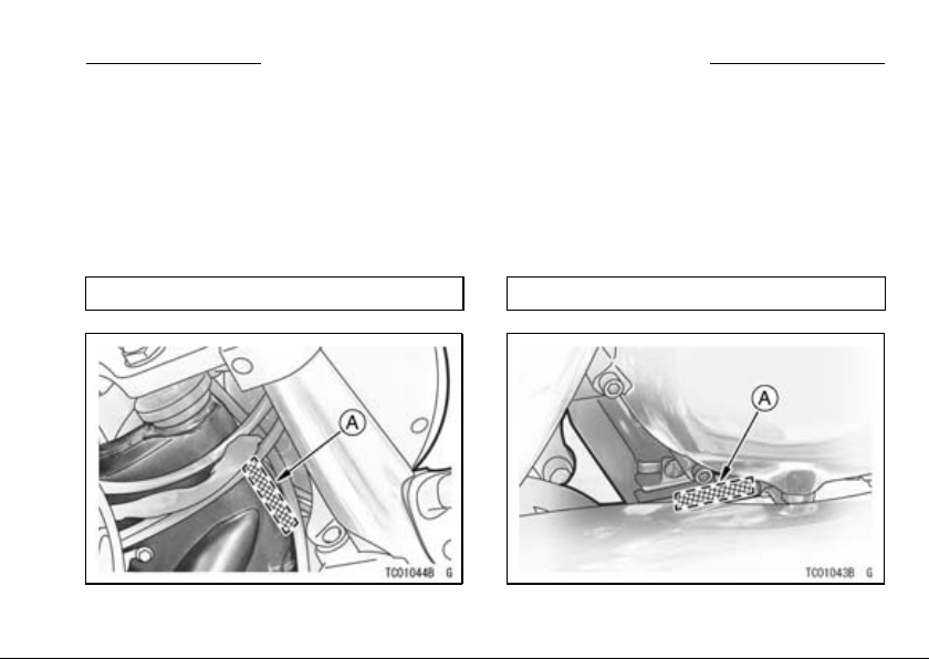
SERIAL NUMBER LOCATIONS
The engine and frame serial numbers are used to register the motorcycle. They
are the only means of identifying your particular machine from others of the same
model type. These serial numbers may be needed by your dealer when ordering
parts. In the event of theft, the investigating authorities will require both numbers
as well as the model type and any peculiar features of your machine that can help
them id entify it.
Frame No.
A. Frame Number
Engine N o.
A. Engine Number
14 LOCATION OF PARTS
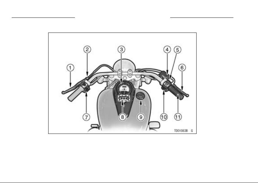
LOCATION OF PARTS
1. Clutch Lever
2. Clutch Lever Adjuster
3. Meter Instruments
4. Brake Fluid Reservoir
(Front)
5. Brake Lever Adjuster
6. Front Brake Lever
7. Left Handlebar
Switches
8. Indicator Lights
9. Fuel Tank C ap
10. R igh t Handlebar
Switches
11. Throttle G rip
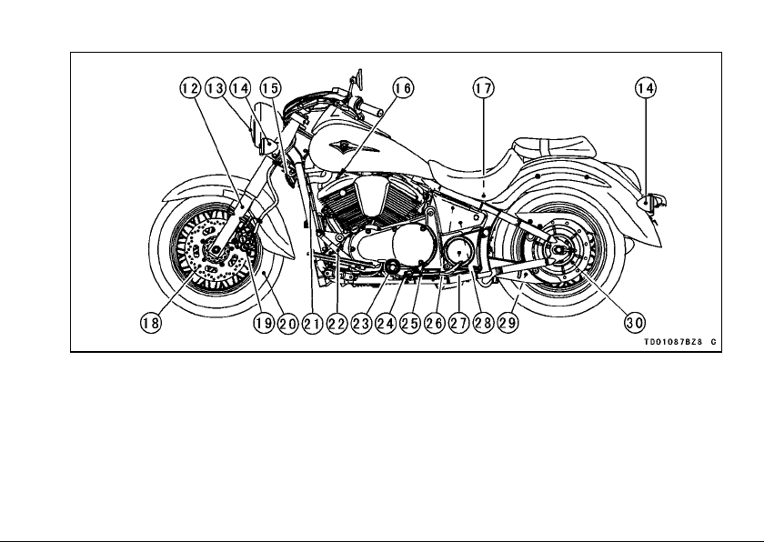
LOCATION OF PARTS 15
12. Front Fork
13. Headlight
14. Turn Signal Light
15. Ho rn
16. Spark Plugs
17. Battery
18. Brake Disc
19. B rake Caliper
20. Wh eel
21. R adiator
22. Shift Pedal
23. Oil Level Inspection
Window
24. Side Stand Switch
25. Side Stand
26. Fuse Box
27. Coolant Reserve Tank
28. Rear Shock Absorber
29. Belt
30. Belt Pulley
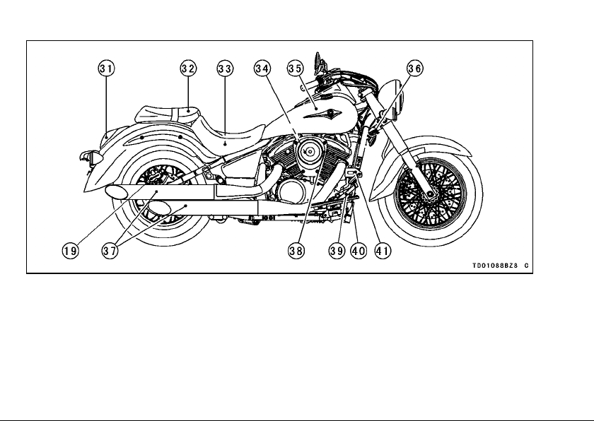
16 LOCATION OF PARTS
31. Tail/Brake Light
32. S eat
33. Tool Kit Case/Tool Kit
34. Air Cleaner Element
35. Fu el Tank
36. Steering Lock
37. Mufflers
38. Idle Speed Adjusting
Screw
39. Rear Brake Pedal
40. R ear Brake Light
Switch
41. B rake Fluid Reservoir
(Rear)
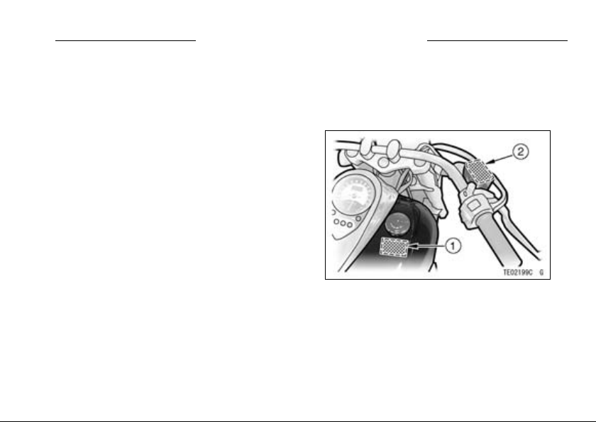
LOCATION OF LABELS
LOCATION OF LABELS 17
All warning labels which are on your
vehicle are repeated here. Read labels
on your vehicle and understand them
thoroughly. They contain information
which is important for your safety and
the safety of anyone else who may operate you r vehicle. Therefore, it is very
important that all warning labels be on
your vehicle in the locations shown. I f
any label is missing, damaged, or worn,
get a replacement from your Kawasaki
dealer and install it in the correct position.
NOTE
The sample warning labels in this
○
section have part numbers to help
you and your dealer obtain the correct replacement.
Refer to the actual vehicle label for
○
model specific data grayed out in th e
illustration.
*1. Fuel Level
*2. Brake Fluid (Front)
(For further information of label, refer to
the “LABEL INFORMATION” chapter.)
*: only on California model
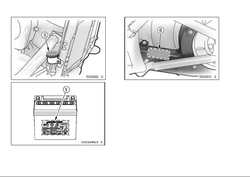
18 LOCATION OF LABELS
3. Brake Fluid (Rear)
5. Battery Position/Danger
6. Tire and Load Data
(For further information of label, refer to
the “LABEL INFORMATION” chapter.)
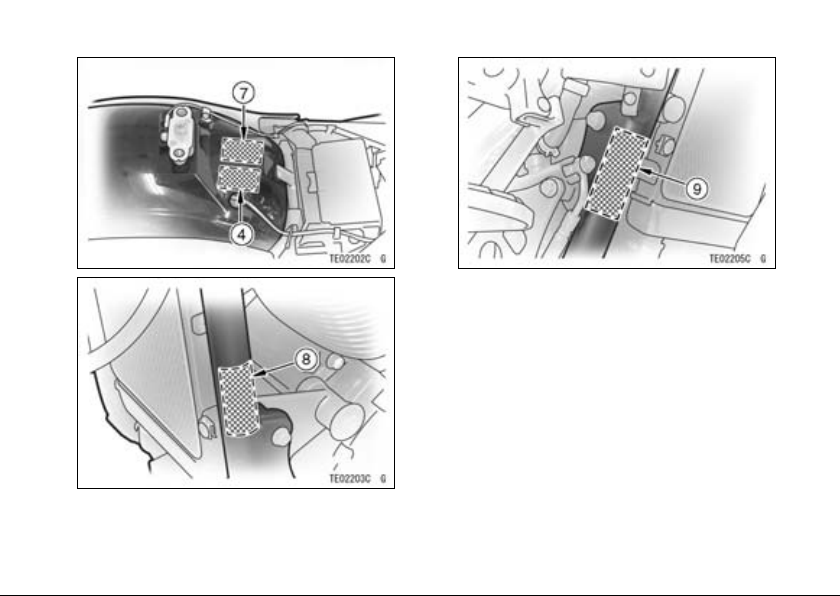
LOCATION OF LABELS 19
*4. Vacuum Hose Routing Diagram
7. Vehicle Emission Control
Information
8. No ise Emission Control Information
9. Weigh t and Manufacture
(For further information of label, refer to
the “LABEL INFORMATION” chapter.)
*: only on California model
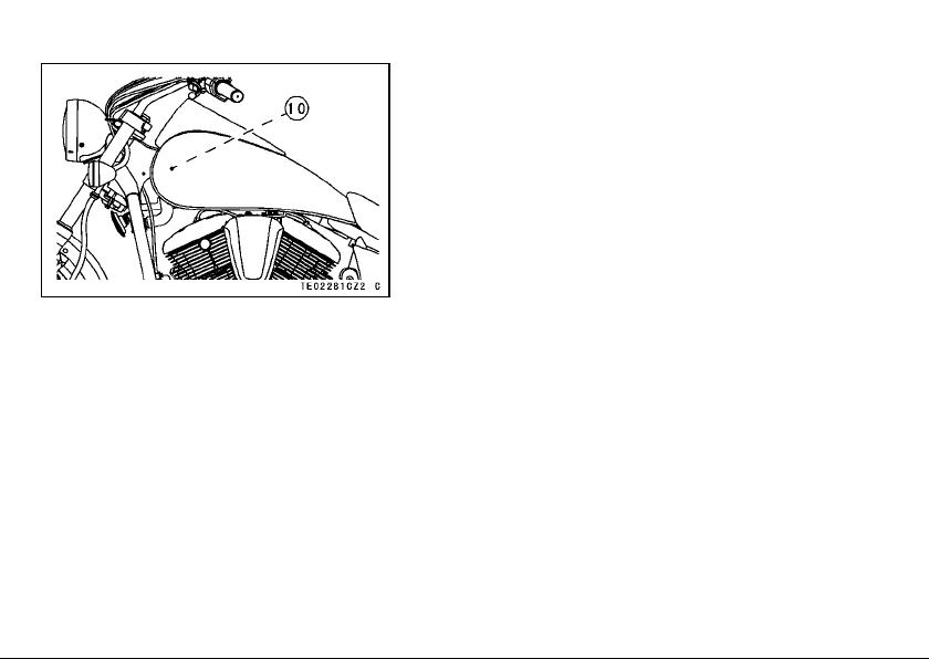
20 LOCATION OF LABELS
10. Radiator Cap Danger
(For further information of label, refer to
the “LABEL INFORMATION” chapter.)
LOADING INFORMATION
LOADING INFORMATION 21
WARNING
Incorrect loading, improper installation or use of accessories,
or modification of your motorcycle may result in an unsafe riding
condition. Before you ride the
motorcycle, make sure it is not
overloaded and that you have
followed these instructions.
With the exception of genuine
Kawasaki Parts and Accessories,
Kawasaki has no control over the
design or application of accessories.
In some cases, improper installation
or use of accessories, or motorcycle
modification, will void the motorcycle
warranty. In selecting and using accessories, and in loading the motorcycle,
you are personally responsible for your
own safety and the safety of other persons involved .
NOTE
Kawasaki Parts and Accessories
○
have been specially designed for
use on Kawasaki motorcycles. We
strongly recommend that all parts
and accessories you add to your
motorcycle be genuine Kawasaki
components.
Because a motorcycle is s en sitive to
changes in weight and aerodynamic
forces, you must take extreme care
in carrying cargo, passengers and/or
in the fitting of additional accessories.
The following general guidelines have

22 LOADING INFOR M ATION
been prepared to assist you in making
your determinations.
1. Any passenger should be thoroughly familiar with motorcycle operation. The passenger can affect
control of the motorcycle by improper positioning during cornering
and sudden movements. It is important that the passenger sit still while
the motorcycle is in motion and not
interfere with the operation of the
motorcycle. Do not carry animals
on your motorcycle.
2. You should instruct any passenger
before riding to keep his feet on the
passenger footpegs and hold on to
the operator or seat strap. Do not
carry a passenger unless he or she
is tall enough to reach the footpegs
and footpegs are provided.
3. All baggage should be carried as
low as possible to reduce the effect
on the motorcycle center of gravity.
Baggage weight should also be distributed equally on both sides of the
motorcycle. Avoid carrying baggage
that extends beyond the rear of the
motorcycle.
4. Baggage should be securely attached. Make sure that the baggage
will not move around while you are
riding. Recheck baggage security
as often as possible (not while the
motorcycle is in motion) and adjust
as necessary.
5. Do not carry heavy or bulky items on
a luggage rack. They are designed
for light items, and overloading can
affect handling due to changes in
weight distribution and aerodynamic
forces.
6. Do not install accessories or carry
baggage that impairs the performance of the motorcycle. Make
sure that you have not adversely

LOADING INFORMATION 23
affected any lighting components,
road clearance, banking capa bility
(i.e., lean angle), control operation,
wheel travel, front fork movement,
or any other aspect of the motorcycle’s operation.
7. Weight attached to the handlebar or
front fork will increase the mass of
the steering assembly and can r esult in an unsafe riding condition.
8. Fairings, windshields, backrests,
and other large items have the capability of adversely affecting stability and handling of the motorcycle,
not only because of their weight, but
also due to the aerodynamic forces
acting on these surfaces while the
motorcycle is in operation. Poorly
designed or installed items can result in an unsafe riding condition.
9. This motorcycle was not intended
to be equipped with a sidecar or to
be used to tow any trailer or other
vehicle. Kawasaki does not manufacture sidecars or trailers for motorcycles and cannot predict the effects of such accessories on handling or stability, but can only warn
thattheeffectscanbeadverseand
that Kawasaki cannot assume responsibility for the results of such
unintended use of the motorcycle.
Furthermore, any adverse effects on
motorcycle components caused by
the use of such accessories will not
be remedied under warranty.
Maximum Load
Weight of rider, passenger, baggage,
and accessories must not exceed 180 kg
(397 lb).
24 GENERAL INFORM ATION
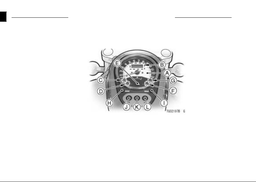
Meter Instruments
A. Speedometer
B. Digital Display
C. Fuel Level Warning
Indicator Light
D. Coolant Temperature
Warning Indicator Light
E. Fuel Gauge
F. Oil Pressure Warning
Indicator Light
G. Fuel Injectio n Warning
Indicator Light
H. MODE Button
I. RESET Button
J. Neutral Indicator Light
K. Turn Signal indicator Light
L. High Beam Indicator Light
GENERAL INFORMATION
GENERAL INFORMATION 25
Speedometer:
The speedometer shows the speed
of the vehicle.
Digital Display
The digital display located in the
speedometer face is used to display
the odometer, trip m eter, and clock.
Pushing the MODE button shifts the
display through the following three
modes: ODO, TRIP and CLOCK.
When the ignition key is turned to
“ON”, all the segments are displayed
for a few seconds, then the clock or
meters operates normally depending
on the mode selected.
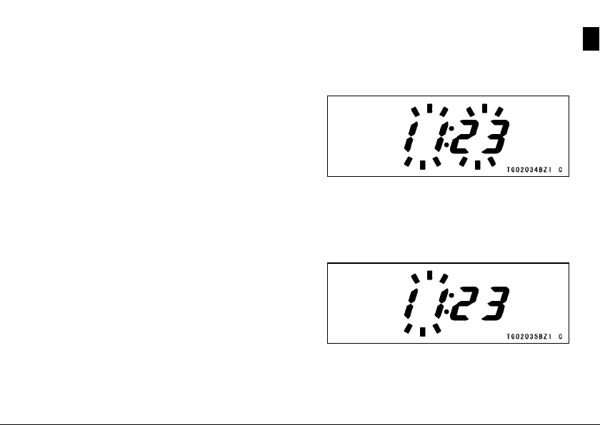
Clock -
To adjust hours and minutes:
Turn the ig nition key to “ON”.
•
PushtheMODEbuttontodisplaythe
•
clock.
Push the RESET button f or more
•
than two seconds. Both the hour and
minute displays start flashing.
Again push the RESET button.
•
When only the hour display flashes,
push the MODE button to advance
the hours.
Push the RESET button. The hour
•
display stops flashing and the minute
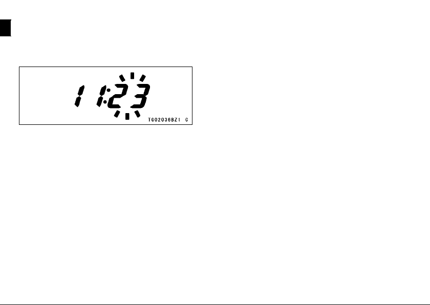
26 GENERAL INFORM ATION
display starts flashing. Push the
MODEbuttontoadvancetheminutes.
Push the RES ET button. Both the
•
hour and minute displays start flashing again.
Push the MODE button. The dis-
•
plays stop flashing and the clock
starts working.
NOTE
Pushing the MODE button momen-
○
tarily advances the hour or minute
step by step. Pushing and holding the button advance the hour or
minute continuously.
The clock works normally fro m the
○
back-up power while the ignition
switch is turned off.
When the battery is disconnected,
○
the clock resets to 1:00, and starts
working again when the battery is
connected.
GENERAL INFORMATION 27
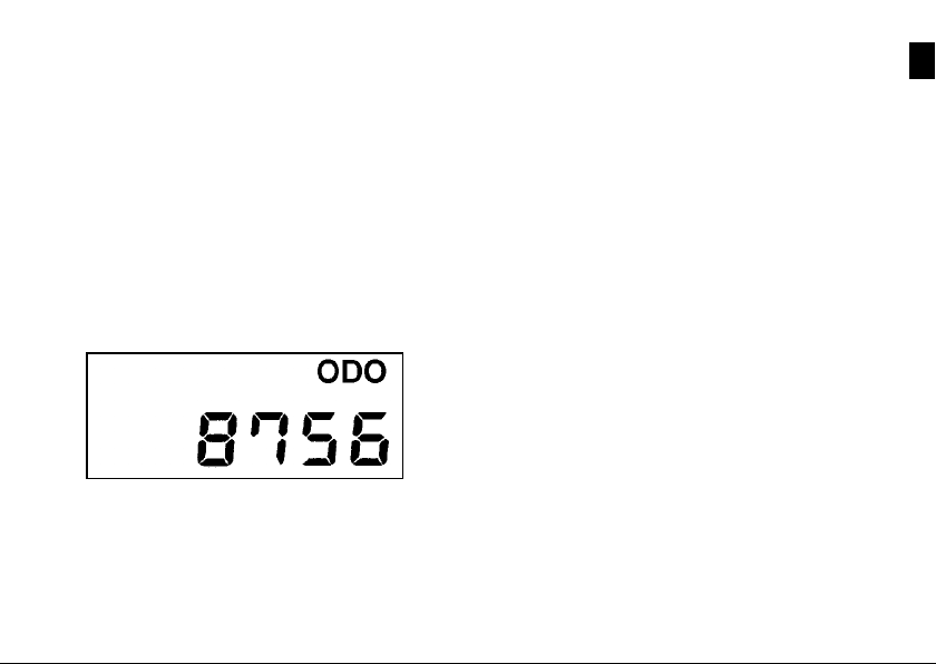
Odometer -
The odo meter sh ows the total distance in kilometers (miles) that the vehicle has been ridden. This meter cannot be reset.
NOTE
The data is maintained even if the
○
battery is disconnected.
When the figures come to 999999,
○
they are stopped and locked.
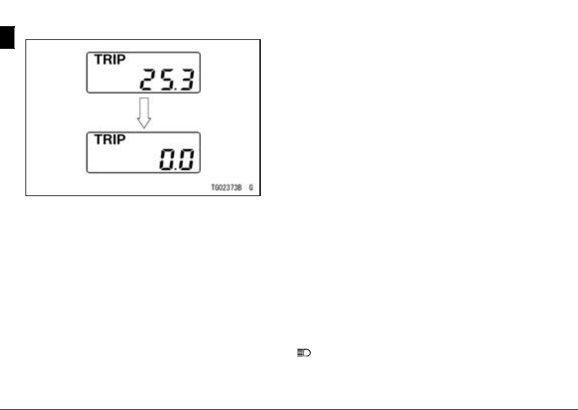
Trip Meters -
The trip meter shows the distance in
kilometers (miles) traveled since it was
last reset to zero.
To reset a trip meter:
Push the MODE b utton to display the
•
trip meter.
Push the RESET button and hold it
•
in.
After two seconds, the figure display
•
turns to 0.0, and then starts cou nting
when the vehicle is operated. The
meter counts until it is next reset.
28 GENERAL INFORM ATION
NOTE
The data is maintained by the back
○
-up power if the ignition key is turned
to “OFF”.
When the trip meter reaches 999.9
○
while riding, the meter resets to 0.0
and continue counting.
When the battery is disconnected,
○
the m eter display resets to 0.0.
Fuel Gauge:
The fuel gauge shows the amount of
fuel in the fuel tank. When the needle
comes near the E (empty) po sition, refuel at the earliest opportunity.
Whenvehiclestandswithsidestand,
fuel gauge cannot show the amount of
fuel in the fuel tank exactly. Stand upright the vehicle to check the fuel level.
RESET Button/MODE button:
The RESET button is used to reset the trip meter and to adjust the
clock. The MODE button is used to
shift through the digital display m odes
and to adjust the clock.
Warning/Indicator Lights:
N: When the transmission is in neutral,
the neutral indicator light is lit.
: When the headlight is on high
beam, the high beam indicator light is
lit.
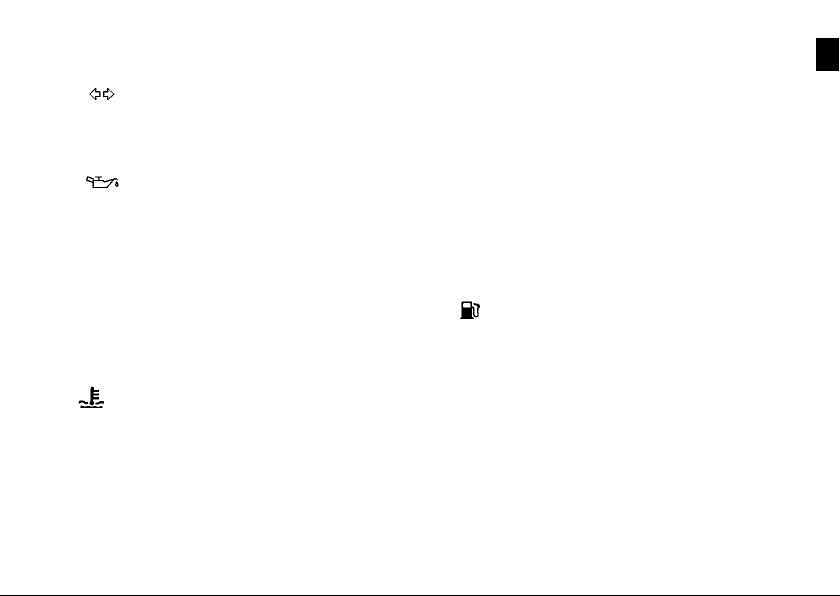
: When the turn signal switch is
pushed to left or right, the turn signal
indicator light flashes on and off.
: The oil pressure warning indicator light goes on whenever the oil pressure is dangerously low or the ignition
switch is in the ON position with the engine not running, and goes off when the
engine oil pressure is high enough. Refer to the Maintenance and Adjustment
chapter for more detailed engine oil information.
: The warning indicator light goes
on whenever the coolant temperature
rises to 120°C (248°F) or higher when
the m otorcycle is in operation. If it
stays on, stop the engine and check the
coolant level in the reserve tank after
the engine cools down.
GENERAL INFORMATION 29
FI: The fuel injection (FI) warning in-
dicator light goes on when the ignition
key is turned to “ON” and goes off soon
after ensuring that its circuit functions
properly. The warning indicator light
also goes on whenever the troubles occur in digital fuel injection system (DFI).
If the w arn ing indicator light comes on,
have the DFI system checked by a n authorized Kawasaki dealer.
: The fuel level warning indicator
light goes on when approximately 4.0 L
(1.0 US gal) of usable fuel remains. Refuel at the earliest opportunity when the
fuel level warning indicator light comes
on with the engine running.
When vehicle stands with side stand,
fuel level warning indicator light cannot
show the amount of fuel in the fuel tank
exactly. Stand upright the vehicle to
check the fuel level.
 Loading...