

Kawasaki Jet Ski Ultra 150, Ultra 150, JH1200-B1, JH1200-B2, JH1200-B3 Service Manual
ULTRA150
JET SKI
Service Manual
®
Watercraft

Quick Reference Guide
General Information 1 j
Periodic Maintenance 2 j
Fuel System 3 j
Engine Lubrication System 4 j
Exhaust System 5 j
Engine Top End 6 j
Engine Removal/Installation 7 j
Engine Bottom End 8 j
This quick reference guide will assist
you in locating a desired topic or procedure.
•Bend the pages back to match the
black tab of the desired chapter number with the black tab on the edge at
each table of contents page.
•Refer to the sectional table of contents
for the exact pages to locate the specific topic required.
Cooling a nd Bilge System 9 j
Drive System 10 j
Pump and Impeller 11 j
Steering 12 j
Hull/Engine Hood 13 j
Electrical System 14 j
Storage 15 j
Appendix 16 j

LIST OF ABBREVIATIONS
A ampere(s) lb pound(s)
ABDC after bottom dead center m meter(s)
AC alternating current min minute(s)
ATDC after top dead center
BBDC before bottom dead center Pa pascal(s)
BDC bottom dead center PS horsepower
BTDC before top dead center psi pound(s) per square inch
°C degree(s) Celsius r revolution
DC direct current rpm revolution(s) perminute
F
°F degree(s) Fahrenheit TIR total indicator reading
ft foot, feet Vvolt(s)
ggram(s) W watt(s)
h hour(s) Ω ohm(s)
L liter(s)
farad(s)
N
TDC
newton(s)
top dead center
Read OWNER’S MANUAL before operating.

MAINTENANCE AND ADJUSTMENTS
Maintenance, replacement, or repair of the emission control devices and systems may
be performed by any marine Sl engine repair establishment or individual.
EMISSION CONTROL INFORMATION
Fuel Information
THIS ENGINE IS CERTIFIED TO OPERATE ON UNLEADED REGULAR GRADE GASOLINE
ONLY.
A minimum of 87 octane of the antifknock index is recommended. The antiknock index is
posted on service station pumps.
Emission Control Information
To protect the environment in which we all live, Kawasaki has incorporated an exhaust emission control system in compliance with applicable regulations of the United States Environmental
Protection Agency.
Exhaust Emission Control System
This system reduces the amount of pollutants discharged into the atmosphere by the exhaust
of this engine. The fuel, ignition and exhaust systems of this engine have been carefully designed and constructed to ensure an efficient engine with low exhaust pollutant levels.
Maintenance
Proper maintenance and repair are necessary to ensure that watercraft will continue to have
low emission levels. This Service Manual contains those maintenance and repair recommendations for this engine. Those items identified by the Periodic Maintenance Chart are necessary
to ensure compliance with the applicable standards.
Tampering with Emission Control System Prohibited
Federal law prohibits the following acts or the causing thereof: (1) the removal or rendering
inoperative by any person other than for purposes of maintenance, repair, or replacement, of
any device or element of design incorporated into any new engine for the purposes of emission
control prior to its sale or delivery to the ultimate purchaser or while it is in use, or (2) the use
of the engine after such device or element of design has been removed or rendered inoperative
by any person.
Among those acts presumed to constitute tampering are the acts listed below:
Do not tamper with the original emission related parts.
* CDI Ignition System
* Flame Arrester
* Fuel Filter Screen
* Spark Plugs
* Carburetor and internal parts

Foreword
This manual is designed primarily for use b y
trained mechanics in a properly equipped shop.
However, it contains enough detail and basic information to make it useful to the owner who desires to perform his own basic maintenance and
repair work. A basic knowledge of mechanics,
the proper use of tools, and workshop procedures must be understood in order to carry out
maintenance and repair satisfactorily. Whenever the owner has insufficient experience or
doubts his ability to do the work, all adjustments, maintenance, and repair should be carried out only by qualified mechanics.
In order to perform the work efficiently and
to avoid costly mistakes, read the text, thoroughly familiarize yourself with the procedures
before starting work, and then do the work carefully in a clean area. Whenever special tools or
equipment are specified, do not use makeshift
tools or equipment. Precision measurements
can only be made if the proper instruments are
used, and the use of substitute tools may adversely affect safe operation.
For the duration of the warranty period,
we recommend that all repairs and scheduled
maintenance be performed in accordance with
this service manual. Any owner maintenance or
repair procedure not performed in accordance
with this manual may void the warranty.
To get the longest life out of your "JET SKI"
watercraft:
Follow the Periodic Maintenance Chart in the
•
Service Manual.
Be alert for problems and non-scheduled
•
maintenance.
Use proper tools and genuine Kawasaki "JET
•
SKI" watercraft parts. Special tools, gauges,
and testers that are necessary when servicing
Kawasaki "JET SKI" watercraft are introduced
by the Special Tool Manual. Genuine parts
provided as spare parts are listed in the Parts
Catalog.
Follow the procedures in this manual care-
•
fully. Don’t take shortcuts.
Remember to keep complete records of main-
•
tenance and repair with dates and any new
parts installed.
How to Use This Manual
In this manual, the product is divided into
its major systems and these systems make up
the manual’s chapters. The Quick Reference
Guide shows you all of the product’s system
and assists in locating their chapters. Each
chapter in turn has its own comprehensive Table of Contents.
For example, if you want ignition coil information, use the Quick Reference Guide to locate
the Electrical System chapter. Then, use the
Table of Contents on the first page of the chapter to find the Ignition Coil section.
Whenever you see these WARNING and
CAUTION symbols, heed their instructions!
Always follow safe operating and maintenance
practices.
WARNING
This warning symbol identifies special
instructions or procedures which, if not
correctly followed, could result in per-
sonal injury, or loss of life.
CAUTION
This caution symbol identifies special
instructions or procedures which, if not
strictly observed, could result in dam-
age to or destruction of equipment.
This manual contains four more symbols (in
addition to WARNING and CAUTION) which will
help you distinguish different types of information.
NOTE
This note symbol indicates points of par-
○
ticular interest for more efficient and con -
venient operation.
Indicates a procedural step or work to be
•
done.
Indicates a procedural sub-step or how to do
○
the work of the procedural step it follows. It
also precedes the text of a NOTE.
Indicates a conditional step or what action to
take based on the results of the test or inspec-
tion in the procedural step or sub-step it fol-
lows.
In most chapters an exploded view illustration
of the system components follows the Table of
Contents. In these illustrations you will find the
instructions indicating which parts require specified tightening torque, oil, grease or a locking
agent during assembly.

GENERAL INFORMATION 1-1
General Information
Table of Contents
Before Servicing ..................................................................................................................... 1-2
Model Identification................................................................................................................. 1-5
General Specifications............................................................................................................ 1-6
Technical Information-Kawasaki Smart Steering System (Carburetor Type).......................... 1-8
Technical Information-Engine ................................................................................................. 1-12
Technical Information-Propulsion System .............................................................................. 1-18
Technical Information-Igniter .................................................................................................. 1-19
Technical Information-Electrical Parts .................................................................................... 1-22
Unit Conversion Table ............................................................................................................ 1-23
1
1-2 GENERAL INFORMATION
Before Servicing
Before starting to service a watercraft, careful reading of the applicable section is recommended to
eliminate unnecessary work. Photographs, diagrams, notes, cautions, warnings, and detailed descriptions have been included wherever necessary. Nevertheless, even a detailed account has limitations,
a certain amount of basic knowledge is also required for successful work.
Especially note the following:
(1) Adjustments
Adjustments shall be made in accordance with the Periodic Maintenance Chart or whenever
troubleshooting or presence of symptoms indicate that adjustments may be required. Whenever
running of the engine is required during maintenance it is best to have the watercraft in water.
CAUTION
Do not run the engine without cooling water supply for more than 15 seconds, especially
in high revolutionary speed or severe engine and exhaust system damage will occur.
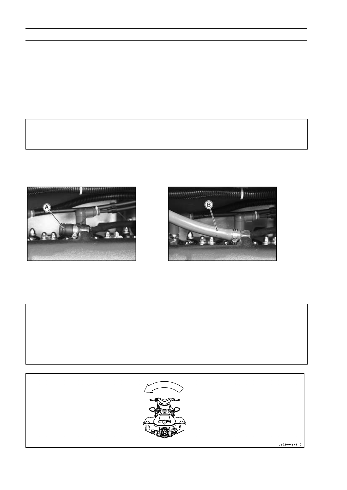
(2) Auxiliary Cooling
An auxiliary cooling supply may be used if the watercraft cannot be operated in water during adjustments. If possible, always operate the watercraft in water rather than use an auxiliary cooling
supply.
Loosen the clamp and remove the cap [A].
•
Connect the garden hose [B] to the hose fitting (see above).
•
Attach the garden hose to a faucet. Do not turn on the water until the engine is running and turn
•
it off immediately when the engine stops. The engine-requires 2.4 L/min (2.5 qts/min) at 1 800
r/min (rpm) and 7.0 L/min (7.4 qts/min) at 6 000 r/min (rpm).
CAUTION
Insufficient cooling supply will cause the engine and/or exhaust system to overheat and
severe damage will occur. Excessive cooling supply may kill the engine and flood the cylinders, causing hydraulic lock. Hydraulic lock will cause severe damage to the engine. If the
engine dies while using an auxiliary cooling supply, the water must be shut off immediately.
Always turn the boat on its left side. Rolling to the right side can cause water in the exhaust
system to run into the engine, with possible engine damage.

GENERAL INFORMATION 1-3
Before Servicing
(3) Dirt
Before removal and disassembly, clean the “Jet Ski” watercraft. Any sand entering the engine
will shorten the life of the watercraft. For the same reason, before installing a new part, clean off
any dust or metal filings.
(4) Battery Ground
Disconnect the ground (–) wire from the battery before performing any disassembly operations
on the “Jet Ski” watercraft. This prevents the engine from accidentally turning over while work
is being carried out, sparks from being generated while disconnecting the wires from electrical
parts, as well as damage to the electrical parts themselves. For reinstallation, first connect the
positive wire to the positive (+) terminal of the battery
(5) Installation, Assembly
Generally, installation or assembly is the reverse of removal or disassembly. However, if installation or assembly sequence is given in this Service Manual, follow it. Note parts locations and
cable, wire, and hose routing during removal or disassembly so they can be installed or assembled in the same way. It is preferable to mark and record the locations and routing whenever
possible.
(6) Tightening Sequence
When installing bolts, nuts, or screws for which a tightening sequence is given in this Service
Manual, make sure to follow the sequence. When installing a part with several bolts, nuts, or
screws, start them all in their holes and tighten them to a snug fit, thus ensuring that the part has
been installed in its proper location. Then, tighten them to the specified torque in the tightening
sequence and method indicated. If tightening sequence instructions are not given, tighten them
evenly in a cross pattern. Conversely, to remove a part, first loosen all the bolts, nuts, or screws
that are retaining the part a 1/4-turn before removing them.
(7) Torque
When torque values are given in this Service Manual, use them. Either too little or too much
torque may lead to serious damage. Use a good quality, reliable torque wrench.
(8) Force
Common sense should dictate how much force is necessary in assembly and disassembly. If
a part seems especially difficult to remove or install, stop and examine w hat may be causing the
problem. Whenever tapping is necessary, tap lightly using a wooden or plastic-faced mallet. Use
an impact driver for screws (particularly for the removing screws held by non-permanent locking
agent) in order to avoid damaging the screw heads.
(9) Edges
Watch for sharp edges, as they could cause injury through careless handling, especially during
major engine disassembly and assembly. Use a clean piece of thick cloth when lifting the engine
or turning it over.
(10)High-Flash Point Solvent
A high-flash point solvent is recommended to reduce fire danger. A commercial solvent commonly available in North America is standard solvent (generic name). Always follow manufacturer
and container directions regarding the use of any solvent.
(11) Gasket, O-ring
Replace a gasket or an O-ring with a new part when disassembling. Remove any foreign matter
from the mating surface of the gasket or O-ring to ensure a perfectly smooth surface to prevent
oil or compression leaks.
(12)Liquid Gasket, Locking Agent
Clean and prepare surfaces where liquid gasket or non-permanent locking agent will be used.
Apply them sparingly. Excessive amount may block engine oil passages and cause serious damage.
(13)Press
When using a press or driver to install a part such as a drive shaft holder bearing, apply a small
amount of oil to the area where the two parts come in contact to ensure a smooth fit.
(14)Ball Bearing and Needle Bearing
Do not remove a ball bearing or a needle bearing unless it is absolutely necessary. Replace any
ball or needle bearings that were removed with new ones. Install bearings with the manufacturer
and size marks facing out, applying pressure evenly with a suitable driver. Apply force only to the
end of the race that contacts the press fit portion, and press it evenly over the base component.
1-4 GENERAL INFORMATION
Before Servicing
(15)Oil Seal and Grease Seal
Replace any oil or grease seals that were removed with new ones, as removal generally damages seals. Oil or grease seals should be pressed into place using a suitable driver, applying a
force uniformly to the end of seal until the face of the seal is even with the end of the hole, unless
instructed otherwise. When pressing in an oil or grease seal which has manufacturer’s marks,
press it in with the marks facing out.
(16)Circlip, Retaining Ring, and Cotter Pin
When installing circlips and retaining rings, take care to compress or expand them only enough
to install them and no more. Install the circlip with its chamfered side facing load side as well.
Replace any circlips, retaining rings, and cotter pins that were removed with new ones, as removal weakens and deforms them. If old ones are reused, they could become detached while
the “Jet Ski” watercraft is driven, leading to a major problem.
(17)Lubrication
Engine wear is generally at its maximum while the engine is warming up and before all the sliding
surfaces have an adequate lubricative film. During assembly, make sure to apply oil to any sliding
surface or bearing that has been cleaned. Old grease or dirty oil c ould have lost its lubricative
quality and may contain foreign particles that act as abrasives; therefore, make sure to wipe it off
and apply fresh grease or oil. Some oils and greases in particular should be used only in certain
applications and may be harmful if used in an application for which they are not intended.
(18)Replacement Parts
When there is a replacement instruction, replace these parts with new ones every time they are
removed.
Replacement parts will be damaged or lose their original function once they are removed. Therefore, always replace these parts with new ones every time they are removed. Although the previously mentioned gasket, O-ring, ball bearing, needle bearing, grease seal, oil seal, circlip, and
cotter pin have not been so designated in their res pective text, they are replacement parts.
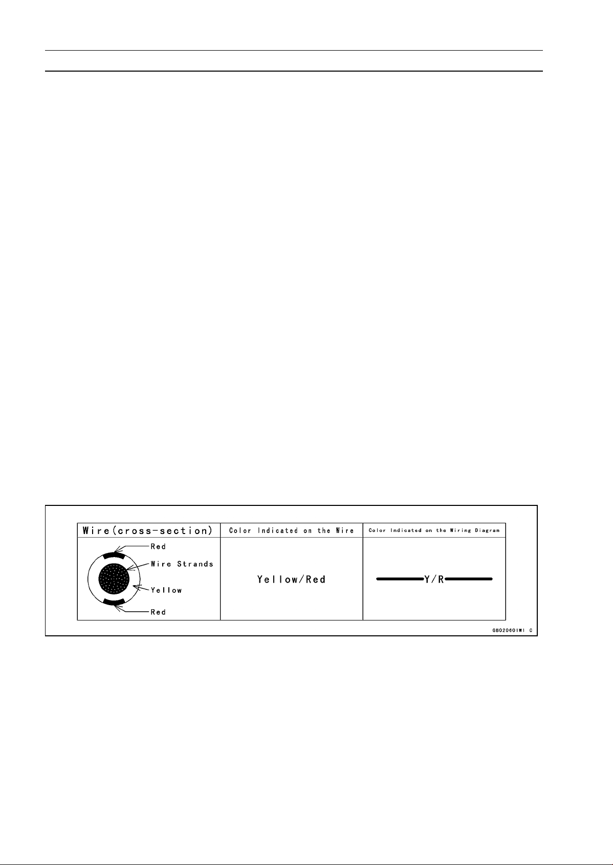
(19)Electrical Wires
All the electrical wires are either one-color or two-color. A two-color wire is identified first by the
primary color and then the stripe color. For example, a yellow wire with thin red stripes is referred
to as a “yellow/red” wire; it would be a “red/yellow” wire if the colors were reversed. Unless instructed otherwise, electrical wires must be connected to wires of the same color.
Two-Color Electrical
(20)Inspection
When parts have been disassembled, visually inspect these parts for the following conditions
or other damage. If there is any doubt as to the condition of them, replace them with new ones.
Abrasion Crack Hardening Warp
Bent Dent
Color change Deterioration Seizure
(21)Specifications
Specification terms are defined as follows:
"Standards" show dimensions or performances which brand-new parts or systems have.
"Service Limits" indicate the usable limits. If the measurement shows excessive wear or deteriorated performance, replace the damaged parts.
Scratch
Wear
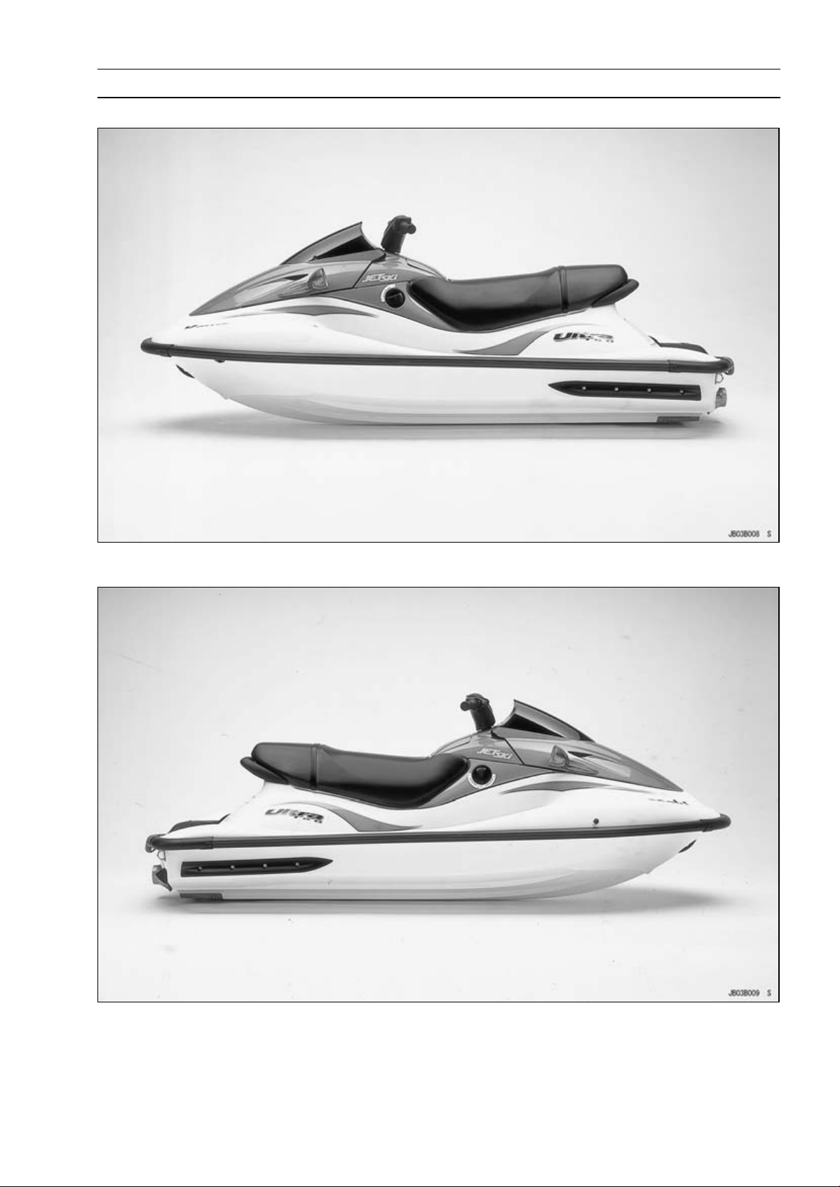
Model Identification
JH1200-B1 Left Side View
GENERAL INFORMATION 1-5
JH1200-B1 Right Side View

1-6 GENERAL INFORMATION
General Specifications
Items JH1200-B1 ∼ B3
Engine
Type 2-stroke, 3-cylinder, crankcase reed valve, water cooled
Displacement 1176mL(71.8cuin.)
Bore and Stroke 80 × 78 mm (3.15 × 3.07 in.)
Compression Ratio 5.8 : 1
Maximum Horsepower 106.6 kW (145 PS) @6 750 r/min (rpm)
Maximum Torque
Ignition System DC-CDI (Digital)
Lubrication System Superlube Oil injection (break-in period: Oil injection and fuel
Carburetion System Keihin CDCV 40-35 × 3
Starting System Electric starter
Tuning Specifications
Spark Plug:
Type NGK BR9ES
Gap 0.7 ∼ 0.8 mm (0.028 ∼ 0.031 in.)
Terminal
Ignition Timing
Carburetor:
Idle Speed
Compression Pressure 675 ∼ 1 070 kPa (6.9 ∼ 10.9 kgf/cm², 98 ∼ 155 psi) @ 440 r/min
Drive System
Coupling Direct drive from engine
Jet Pump:
Type Mixed flow single stage
Thrust
Steering Steerable nozzle
Braking Water drag
Performance
†Minimum Turning Radius 4.0 m (13.1 ft)
†Fuel Consumption 50.5 L/h (13.3 US gal/h) @ full throttle
†Cruising Range 119 km (75 mile) @ full throttle 1 hour and 9 minutes
Dimensions
Overall Length 2 890 mm (113.8 in.)
Overall Width 1 129 mm (44.4 in.)
Overall Height 1 028 mm (40.5 in.)
Dry Weight 284 kg (626 lb)
Fuel Tank Capacity 58 L (15.3 US gal) including 7 L (1.8 US gal) reserve
Engine Oil
Type
Oil Tank Capacity 4.7 L (1.2 US gal)
153.5 N·m (15.6 kgf·m, 112.8 ft·lb) @6 000 r/min (rpm)
mixture50: 1)
Solid post
15° BTDC @1 250 r/min ∼ 22° BTDC @3 500 r/min (rpm)
1 250 ±100 r/min (rpm)-in water
1 800 ±100 r/min (rpm)-out of water
(rpm)
4 020 N (410 kgf, 904 lb)
2-stroke, N.M.M.A. Certified for Service TC-W3

GENERAL INFORMATION 1-7
General Specifications
Items JH1200-B1 ∼ B3
Electrical Equipment
Battery 12 V 18 Ah
Maximum Generator Out Put 5.0 A/14V @6 000 r/min (rpm)
†: This information shown here represents results under controlled conditions, and the information
may not be correct under other conditions.
Specifications subject to change without notice, and may not apply to every country.
1-8 GENERAL INFORMATION
Technical Information-Kawasaki Smart Steering System (Carburetor Type)
Outline
The Kawasaki Smart Steering system provides turning
action under certain conditions when the throttle is released. There must be thrust at the jet nozzle to initiate
and complete turns. This is supplemental steering system
which assists operators in learning to negotiate turns and
maneuver.
The Kawasaki Smart Steering system continuously detects the operator’s steering i nput as well as the boat’s
speed. When the throttle is released while boat speed is
high and a turn is initiated, the smart steering system automatically increases engine speed to provide additional
thrust. The system does not work when the engine is off
or the boat speed is low.
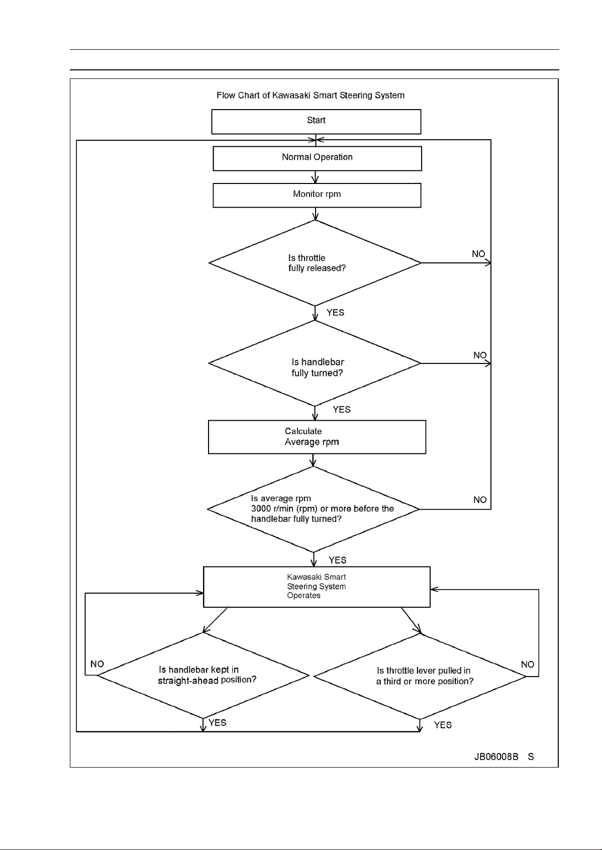
The Kawasaki Smart Steering system functions when all
of these conditions are met.
- engine speed averages more than 3 000 RPM for a specified time
- the throttle is released completely
- and the handlebars are held fully to the left or right.
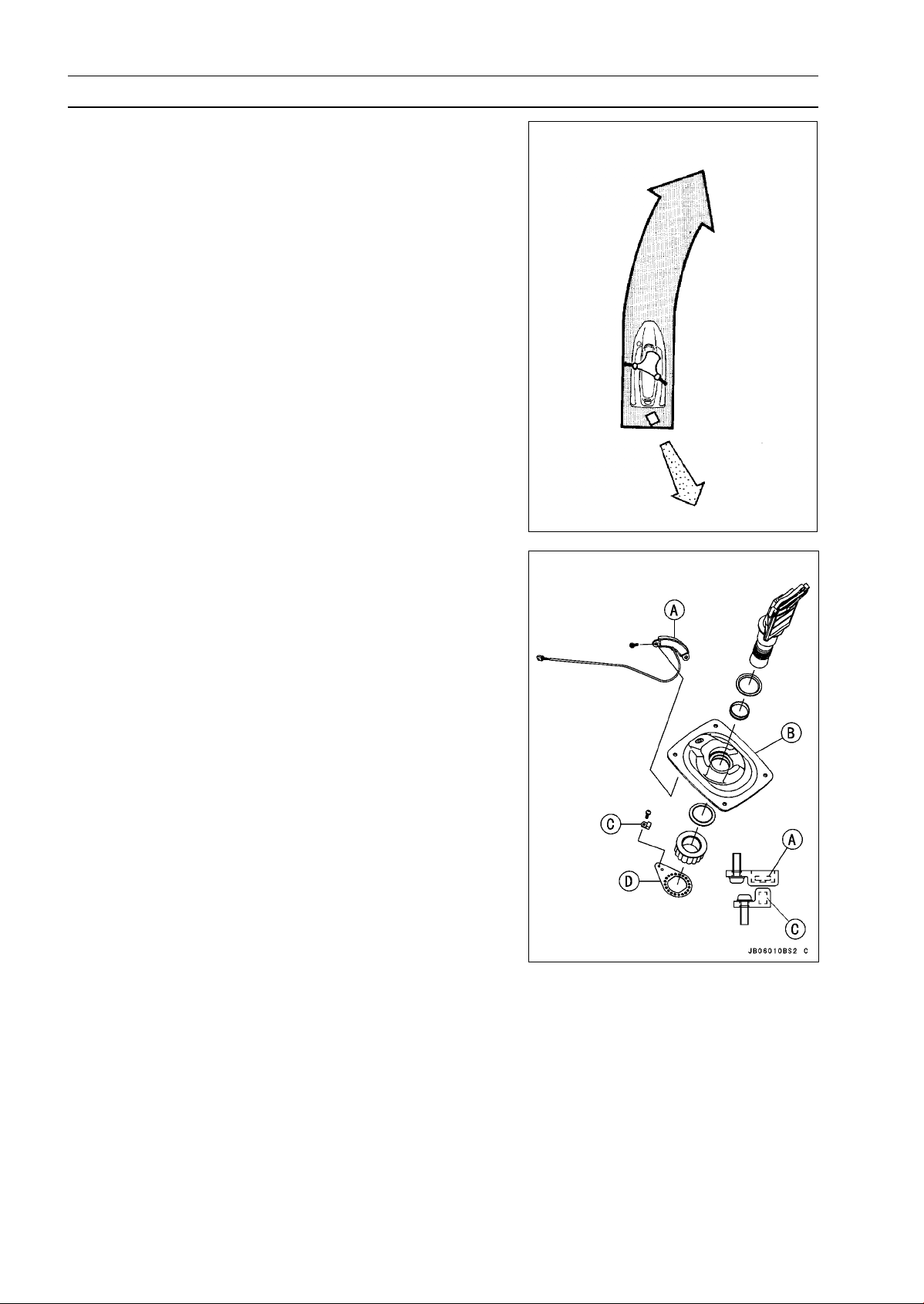
Construction and Operation
The main component parts for the Kawasaki Smart Steering system are the following.
1. Steering Position Sensor and Magnet
2. Throttle Sensor
3. Crankshaft Sensor
4. IC Igniter
5. Smart Steering Actuator
The steering position sensor [A] is installed on the bottom
side of the steering holder [B]. Left and right sensors are
built into the steering position s ensor [A]. The magnet [C] is
installed on the mount plate [D].
When the handlebar is fully turned in either direction, the
magnet [C] under the steering position sensor [A] signals
the steering position sensor [A] to switch ON.
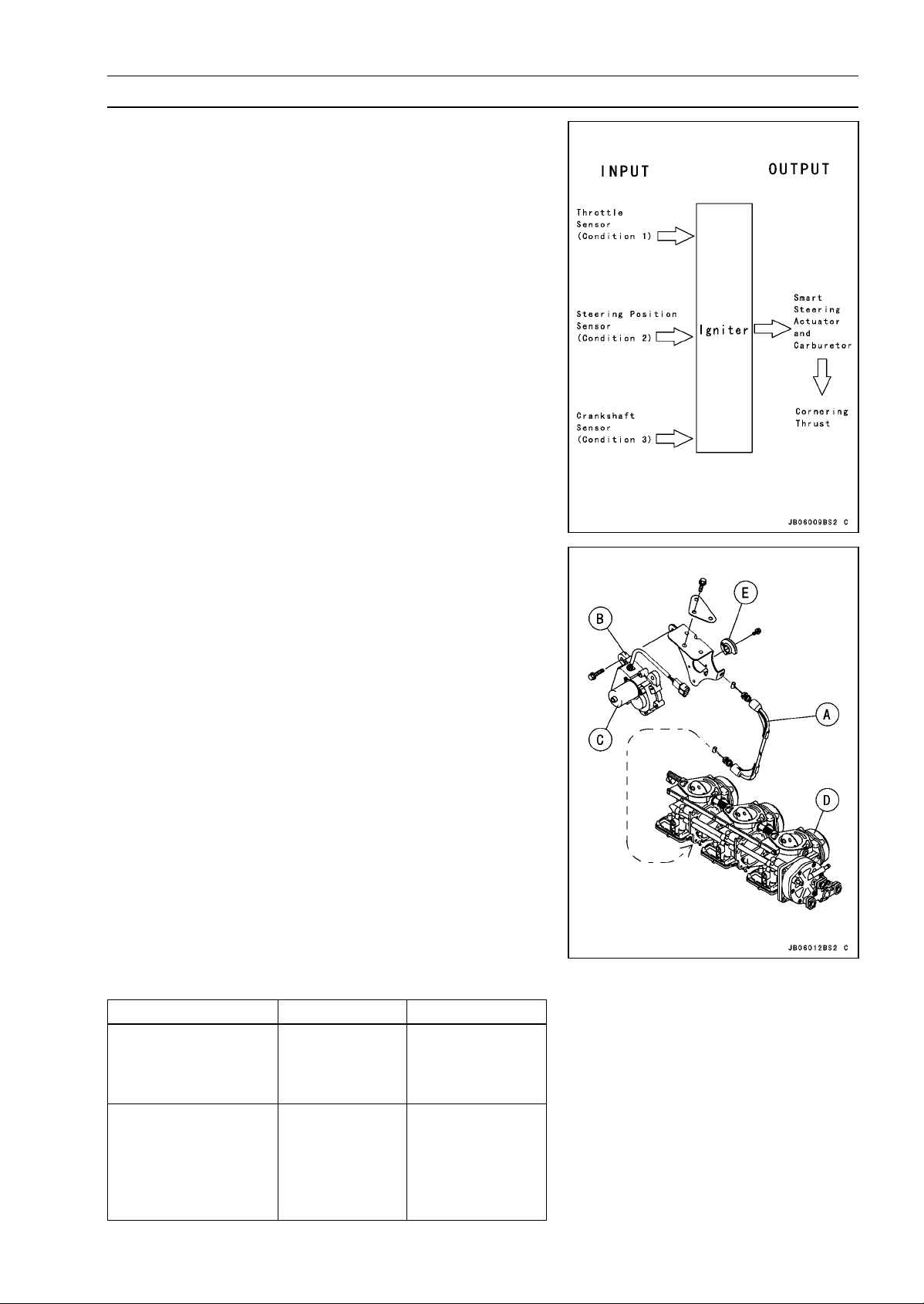
GENERAL INFORMATION 1-9
Technical Information-Kawasaki Smart Steering System (Carburetor Type)
Kawasaki Smart Steering system provides thrust (approx.
2 800 rpm-in water) when the these three conditions are
met.
Condition 1 :
Condition 2: The handlebar is fully turned in either
Condition 3 : The average engine speed for a period of
Throttle is release-The throttle opening angle
of throttle sensor at id le.
direction-The steering position sensor switches
ON.
time before the system operates is 3 000 rpm
or more-The igniter calculates the average
engine speed based on the data sent from the
crankshaft sensor.
The IC igniter will send digital signals for the most adequate actions to the Kawasaki Smart Steering actuator if
three conditions mentioned above are completed.
The Smart Steering cable [A] will be pulled if the actuator
[B] with a built-in s ervo motor [C] receives signals. Engine
speed will be increased (up to approximately 2 800 rpm) by
opening the throttle v alves. This will provide enough thrusts
to allow your personal watercraft to turn.
Carburetor [D]
Pulley [E]
How To Release Kawasaki Smart Steering System
Engine Speed
(When the Kawasaki
Smart Steering system
operates)
How To Release
Kawasaki Smart
Steering System
IN WATER
approx.
2800rpm
Keep the
handlebar in the
straight-ahead
position, or pull
the throttle lever
inathirdormore.
OUTOFWATER
approx.
6 500 rpm
Keep the
handlebar in the
straight-ahead
position, or pull the
throttle lever in a
third or more.
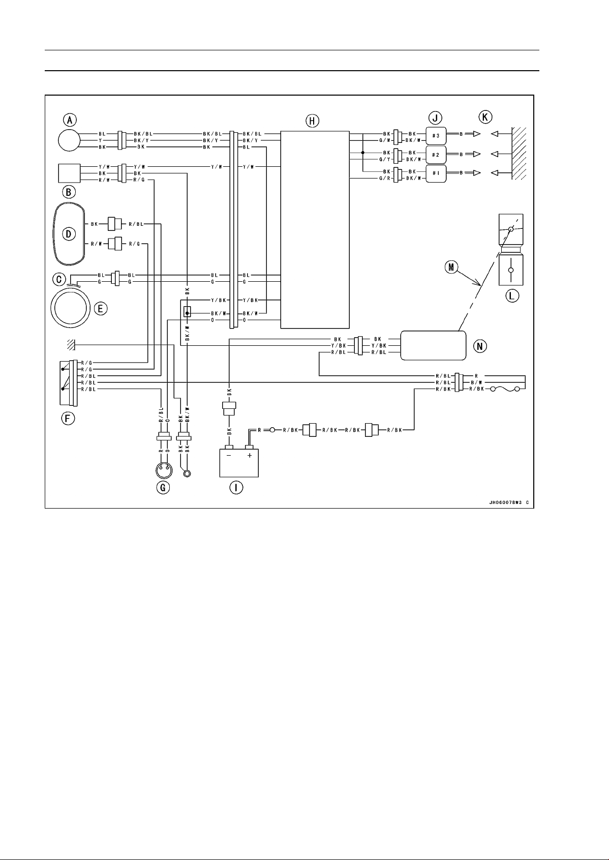
1-10 GENERAL INFORMATION
Technical Information-Kawasaki Smart Steering System (Carburetor Type)
Kawasaki Smart Steering System Circuit
A. Throttle Sensor
B. Steering Position Switch (Steering Position Sensor and Magnet)
C. Crankshaft Sensor
D. Multifunction Meter
E. Magneto
F. Joint Connector
G. Main Switch
H. IC Igniter
I. Battery
J. Ignition Coils
K. Spark Plugs
L. Carburetor
M. Cable
N. Smart Steering Actuator
GENERAL INFORMATION 1-11
Technical Information-Kawasaki Smart Steering System (Carburetor Type)
1-12 GENERAL INFORMATION
Technical Information-Engine
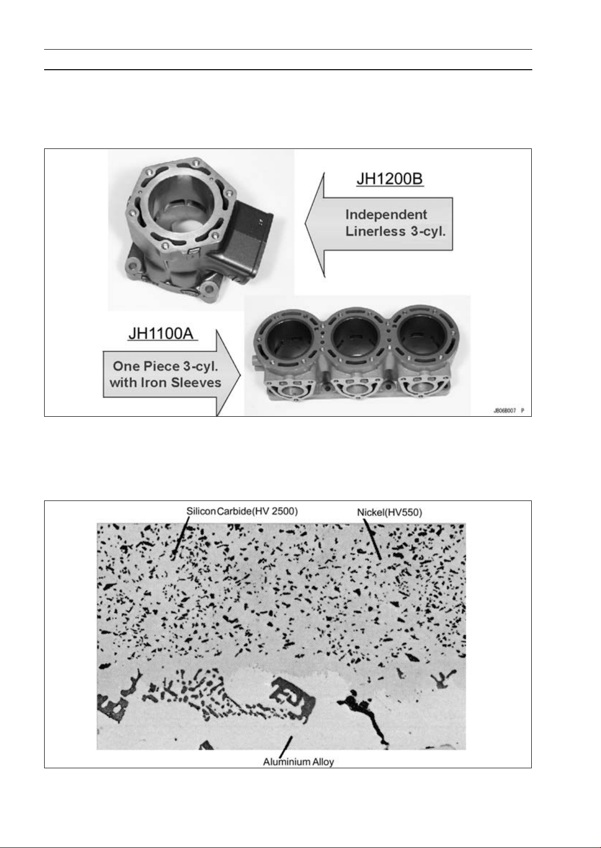
1. Cylinder
This large-displacement engine features independent, Nikasil plated aluminium cylinders for light
weight, long wear and superb heat dispersion characteristics.
Comparison of Cylinders
Nikasil Plating: A film in which silicon carbide (SiC) is combined with nickel (Ni).
The cylinders are made from aluminium alloy for excellent heat transmission. This keeps the surface
temperature of the cylinder-bore lower than is possible with a conventional aluminium cylinder with a
cast-iron sleeve. Assembly and maintenance are improved with independent cylinders.
Nikasil Plating
GENERAL INFORMATION 1-13
Technical Information-Engine
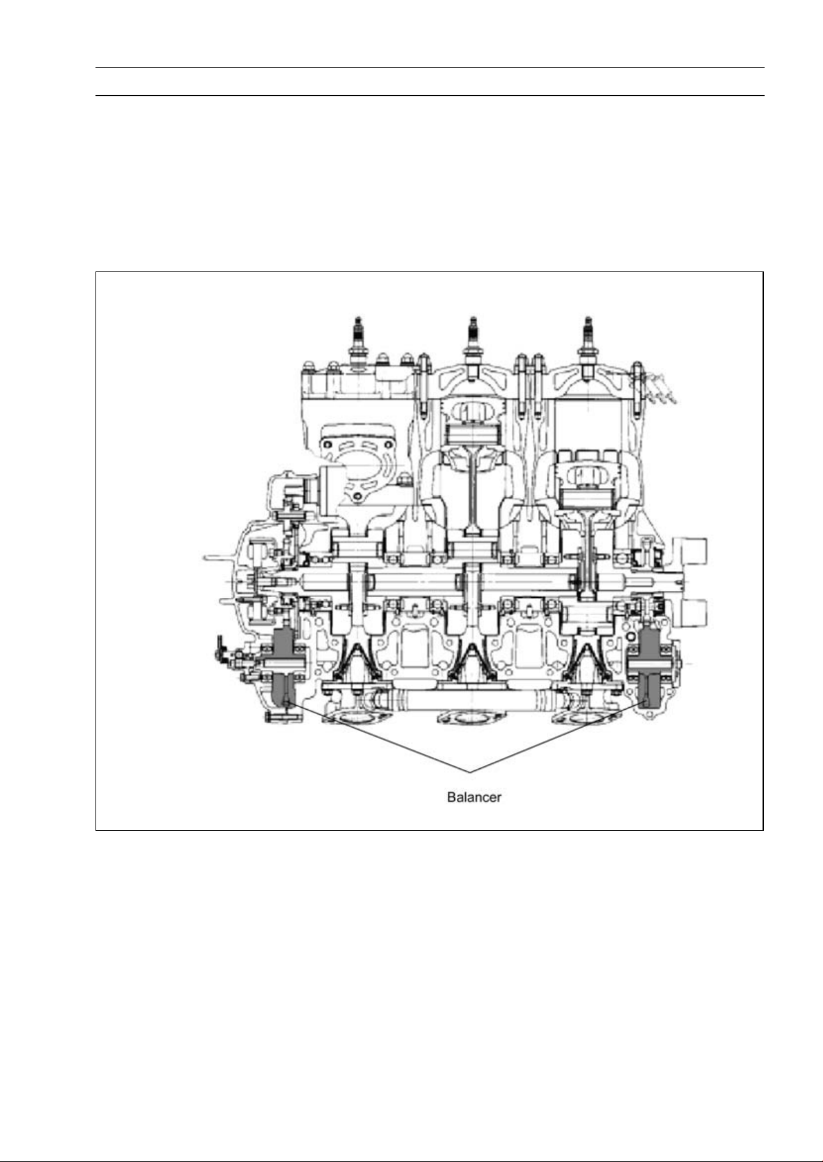
2. Balancer
New counter balancers, one at each end of the crankshaft, decrease vibrations and make this the
smoothest running Kawasaki triple ever produced. When reassembling, it is necessary to match the
marks on the balancer gear and the balancer drive gear. After engine reassembly, the front and rear
balancer oil c hambers must be refilled with engine oil for lubricating the bearings and teeth, since
these chambers are isolated from crankcase chambers.
Front end: 200 mL (12.2 cu in.)
Rear end: 20 mL (1.2 cu in.)
Balancer
1-14 GENERAL INFORMATION
Technical Information-Engine
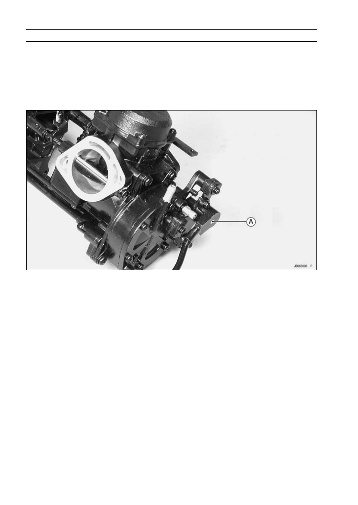
3. Carburetor and Throttle Sensor
The JH1200-B1 has CDCV 40 carburetors with a Throttle Sensor [A]. The CDCV 40 carburetors
deliver sharp throttle response and smooth acceleration. Throttle sensor ensures ideal ignition timing
at all throttle openings, delivering improved response, harder acceleration and improved power feel
at all rpm. The throttle sensor signal goes to the igniter. The igniter computes the optimum ignition
timing. (K-TRIC system)
Throttle Sensor
The Kawasaki JET SKI Watercraft Constant Velocity Carburetor
(1) Development Goals
1) The carburetor must allow high performance with high flexibility to match the engine’s capabilities.
2) The carburetor must have high driveability from low to high engine speeds, responding closely to
the operator’s input.
3) The carburetor must lower exhaust emissions for less harm to the environment.
(2) Features
1) The watercraft CV carburetor has a variable venturi for smoother driveability through the entire
speed range of the engine. It has a vacuum diaphragm which moves a slide in the venturi, and
a needle jet and jet needle. The slide changes the venturi area according to the pressure in the
venturi, and the needle and jet vary the amount of fuel allowed into the venturi.
2) The watercraft CV carburetor is a diaphragm-type carburetor (as opposed to a float bowl-type), and
has all the performance features of the traditional watercraft carburetor: It can operate efficiently
at any angle, it is durable, corrosion resistant, and salt water proof.
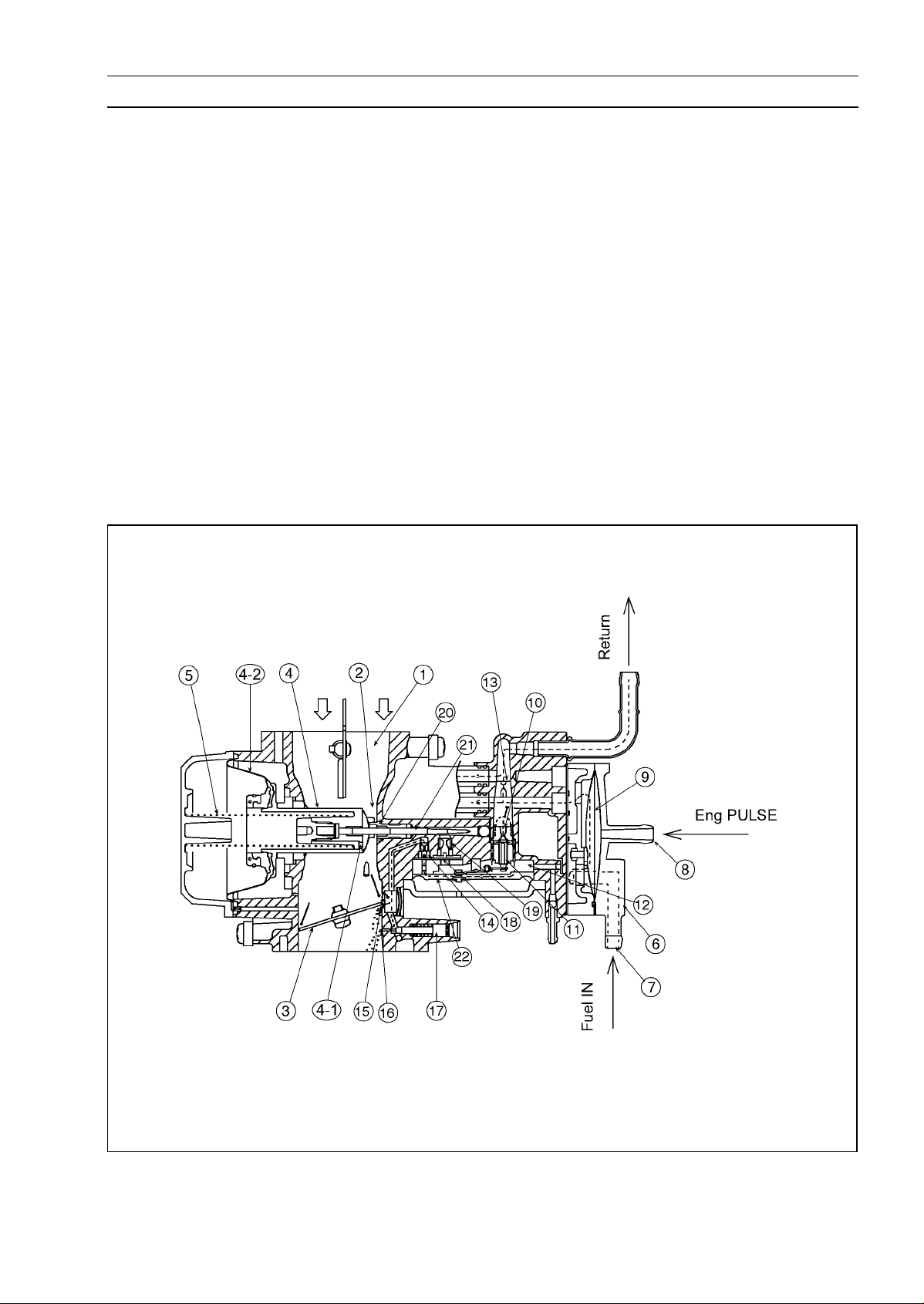
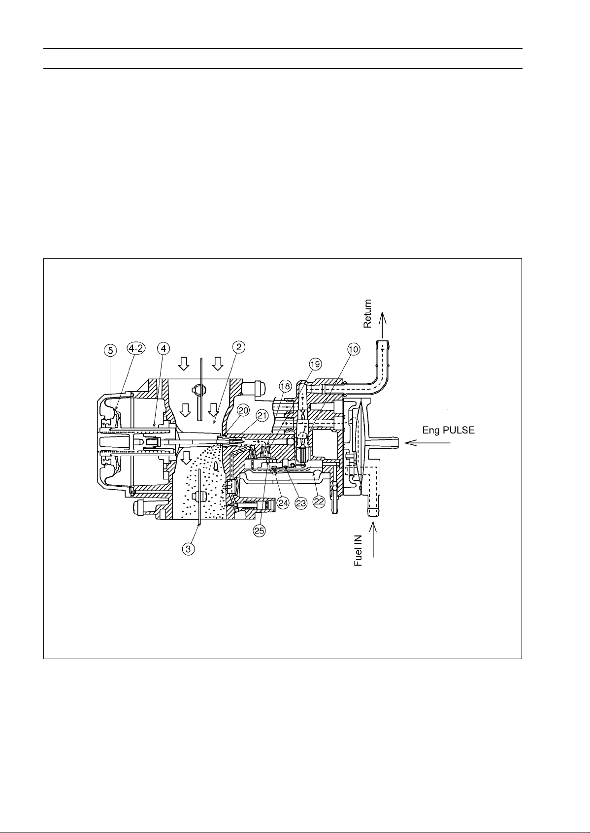
(3) Construction and Function
1) In operation, air is drawn through the intake [1], venturi opening [2], and the throttle valve [3],
and into the engine’s crankcase. The vacuum-actuated slide [4] projects into the venturi, and is
pushed to narrow the venturi opening by the vacuum slide spring [5]. When the engine is running
slowly and the amount of air down into the engine is very small, the slide [4] moves to minimize
the venturi cross sectional area. This maintains the air velocity in the venturi. The bottom of the
slide [4] has a hole [4-1] that goes through into the space above the diaphragm [4-2]. This hole
allows the low pressure in the venturi to draw the slide, against the pressure of the spring [5], out
of the venturi, enlarging the venturi area [2]. The wider the throttle opens, the lower the pressure
in the venturi and the farther the slide moves, opening the venturi so that the engine can speed
up. This mechanism maintains the air speed through the venturi at an even level.
2) The carburetor assembly has a built-in pulse-type fuel pump [6]. Fuel flows from the fuel tank to
the joint [7] on the carburetor assembly and into the fuel pump. As the engine turns, pressure
GENERAL INFORMATION 1-15
Technical Information-Engine
pulses from the crankcase travel through the pulse joint [8] and push the diaphragm [9] in the fuel
pump back and forth, drawing fuel through the check valve in the joint [7] and pushing it past the
needle valve [11], and into the regulator chamber [12]. The needle valve [11] serves the same
purpose as the float valve in a float bowl-type carburetor. If the pump supplies more fuel than the
engine can use, the excess fuel escapes back to the fuel tank through the leak jet [13].
3) The carburetor slow system provides fuel to the engine at low speeds. The slow system consists
of a slow jet [14], various bypass outlets [15], the pilot outlet [16], and the pilot screw [17] As the
throttle valve opens, fuel flows through the pilot outlet [16] and then the bypass outlets [15], one
by one.
4) The main system consists of the check valve [18], the main jet [19], the needle jet [20], and the
jet needle [21]. The jet needle [21] is fixed to the slide and moves with it. As the slide moves,
powered by the diaphragm [4-2], the tapered jet needle [21] moves in and out of the needle jet
[20] varying the clearance between them and thus the fuel flow out of the needle jet.
5) When then engine is idling, the throttle valve [3] is almost closed. The low pressure in the inlet
tract downstream of the throttle valve draws fuel through the pilot outlet [16] and the bypass outlets
[15] from the regulator chamber [12]. Even though the pressure in the venturi [2] is higher on the
upstream side of the throttle valve, almost no fuel flows through the needle jet [20] and into the
regulator chamber [12], because of the check valve [18].
Idling
6) As the fuel in the regulator chamber [12] flows out, the pressure in the chamber drops and draws
the regulator diaphragm [22] into contact with the collar [24] of the float arm [23], which in turn
pulls the needle float valve [11] away from the valve seat [10]. Fuel can now flow into the regulator
chamber [12] and press the diaphragm [22] away from the float arm [23]. This allows the float arm
1-16 GENERAL INFORMATION
Technical Information-Engine
spring [25] to push the arm toward the float valve needle [11] pressing i t into the seat [10], shutting
off the fuel flow.
7) When the throttle valve [3] opens, the engine runs at mid-range or higher speeds. The pressure
in the venturi [2] drops as the air flow speed through it rises. This pressure drop allows the check
valve [18] to open and fuel flows through the main jet [19], the needle jet [20], past the jet needle
[21], and into the venturi [2] on its way into the engine. The low pressure in the venturi [2] also acts
on the diaphragm [4-2], which pulls the slide [4] increasing the area of the venturi. The diaphragm
[4-2] moves the slide until the pressure of the vacuum slide spring [5] is high enough to overcome
the force of the diaphragm. As the slide moves, it pulls the jet needle [21] out of the needle jet
[20], increasing the clearance between the two and allowing more fuel to join the air going to the
engine. The parts on the carburetor are designed to balance the air to fuel ratio for the best fuel
economy, power, driveability, and lowest exhaust emissions.
Full-Open
GENERAL INFORMATION 1-17
Technical Information-Engine
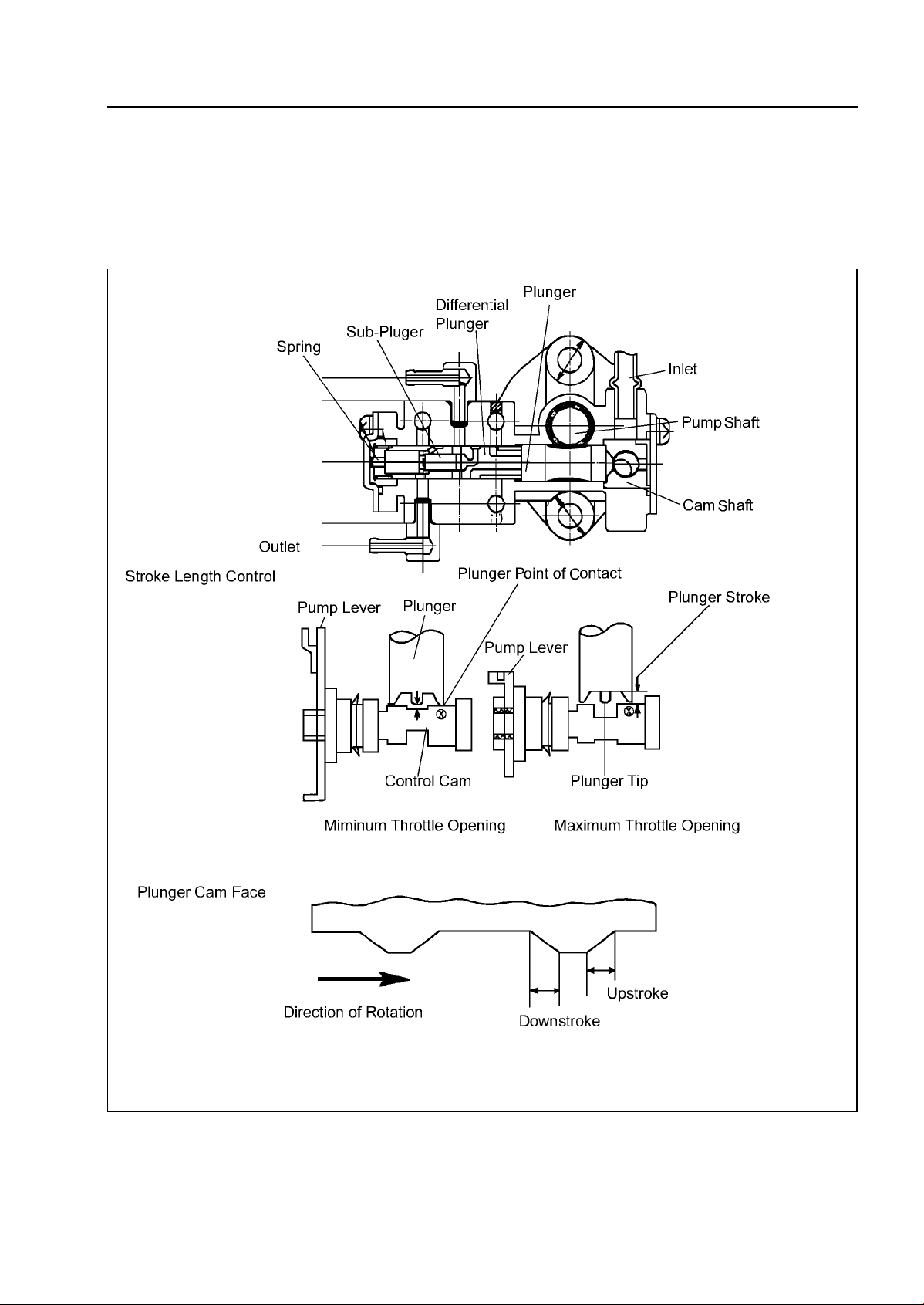
4. Oil Pump
The oil pump output is determined by both engine speed and throttle opening, reducing both oil
consumption and exhaust smoke. This type of pump is often used on 2-stroke motorcycles. The
oil pump has 5 outlet ports. The oil is supplied to each carburetor through 3 outlet ports and to the
balancers through 2 ports for optimum lubrication.
Oil Pump
1-18 GENERAL INFORMATION
Technical Information-Propulsion System
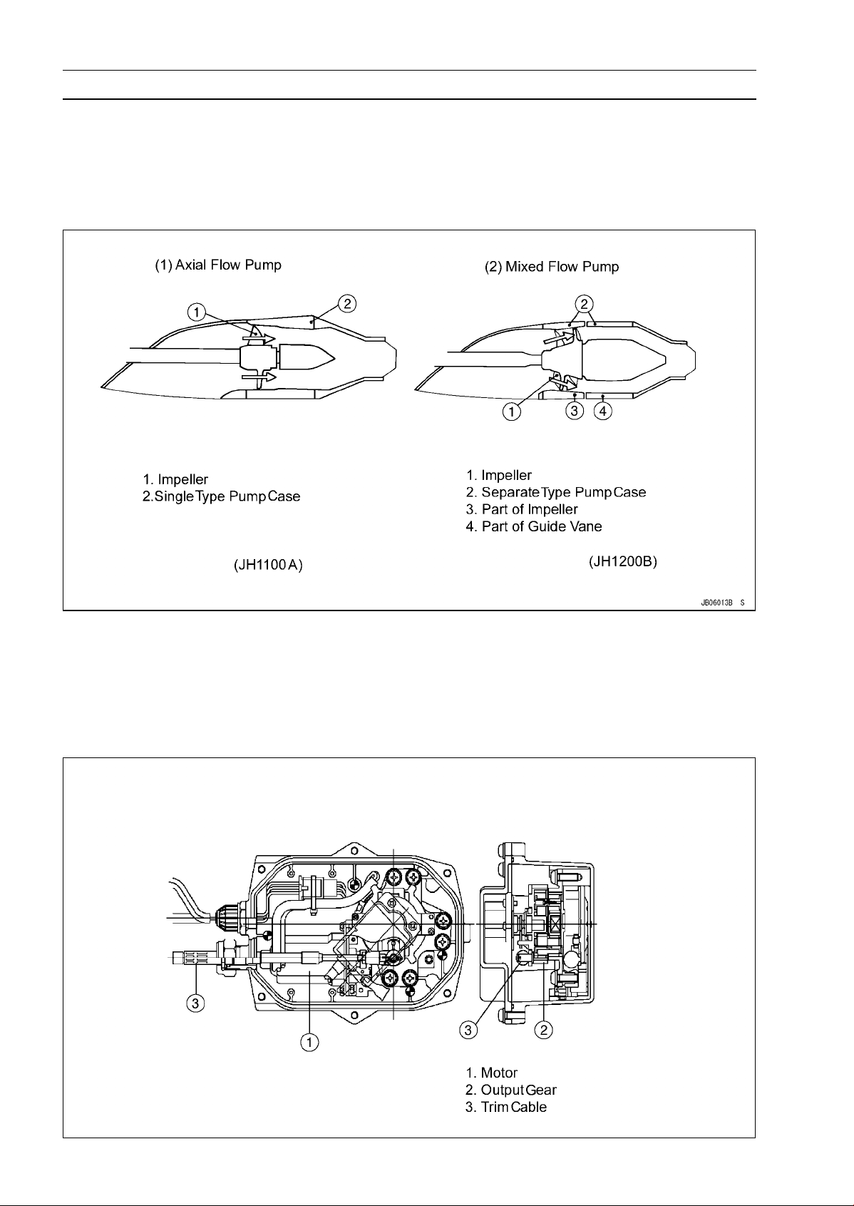
1. Pump
Two kinds of pump are used in PWC for propulsion. The JH1200-B1 has a mixed flow pump. The
mixed-flow pump is compact with high-capacity, and it delivers more efficient propulsion for improved
acceleration and performance.
Pump
Impeller/Pump Case Clearance: STD 0.2-0.3 mm (0.008 ∼ 0.012 in.)
2. Trim Actuator
The JH1200-B1 has a trim, cable driven by the gear system shown below. An input signal revolves
the motor which revolves the sun-gear through a worm gear, and the output gear pulls and pushes
the trim cable. This trim system has a quicker response time than the conventional system.
Trim Actuator
Technical Information-Igniter
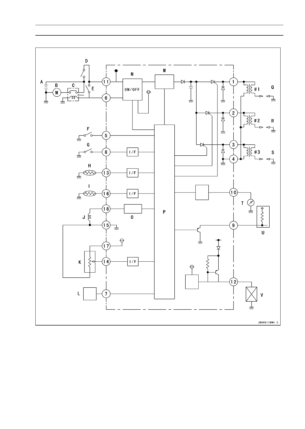
1. Block Diagram of Digital Igniter
GENERAL INFORMATION 1-19
A. Battery
B. Starter
C. Starter Relay
D. Ignition Switch
E. Starter Switch
F. Stop Switch
G. Steering Position Sensor
H. Water Temperature Sensor
I. Inlet Air Temperature Sensor
J. Crankshaft Sensor
K. Throttle Sensor
L. Warning Monitor
M. Power-Source ON/OFF Circuit
N. Wave Shape Circuit
O. DC-DC Converter
P. Control Unit
Q. Ignition Coil #1
R. Ignition Coil #2
S. Ignition Coil #3
T. Tachometer
U. Smart Steering Actuator
V. Outer Load
I/F Interface
1-20 GENERAL INFORMATION
Technical Information-Igniter
2. Functions of Digital Igniter
(1) K-TRIC
The throttle sensor is installed on the throttle body. The output signal is sent to the igniter, which
determines the optimum igniter timing. The K-TRIC system controls the independent timing maps for
each cylinder based on engine speed and throttle opening for quick throttle response.
(2) Correction of Engine Acceleration
The igniter features an acceleration function which advances the timing during rapid acceleration
for improved throttle response. When revs stabilise, timing returns to "normal".
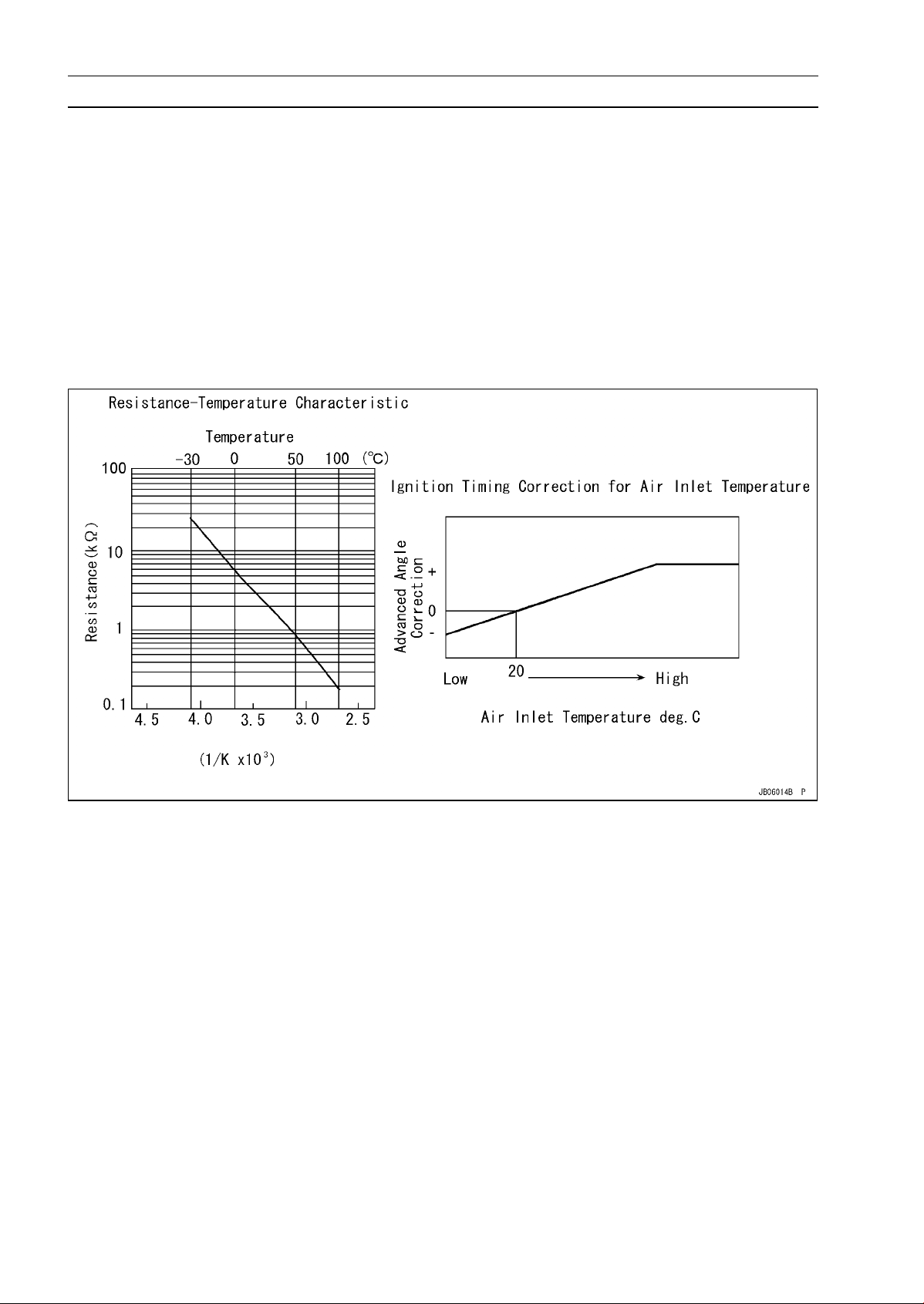
(3) Inlet Air Temperature Correction
The inlet air temperature sensor is installed in the engine room. As the air temperature inside the
hull rises, the igniter compensates by advancing ignition timing to avoid power fade.
Inlet Air Temperature Correction
GENERAL INFORMATION 1-21
Technical Information-Igniter
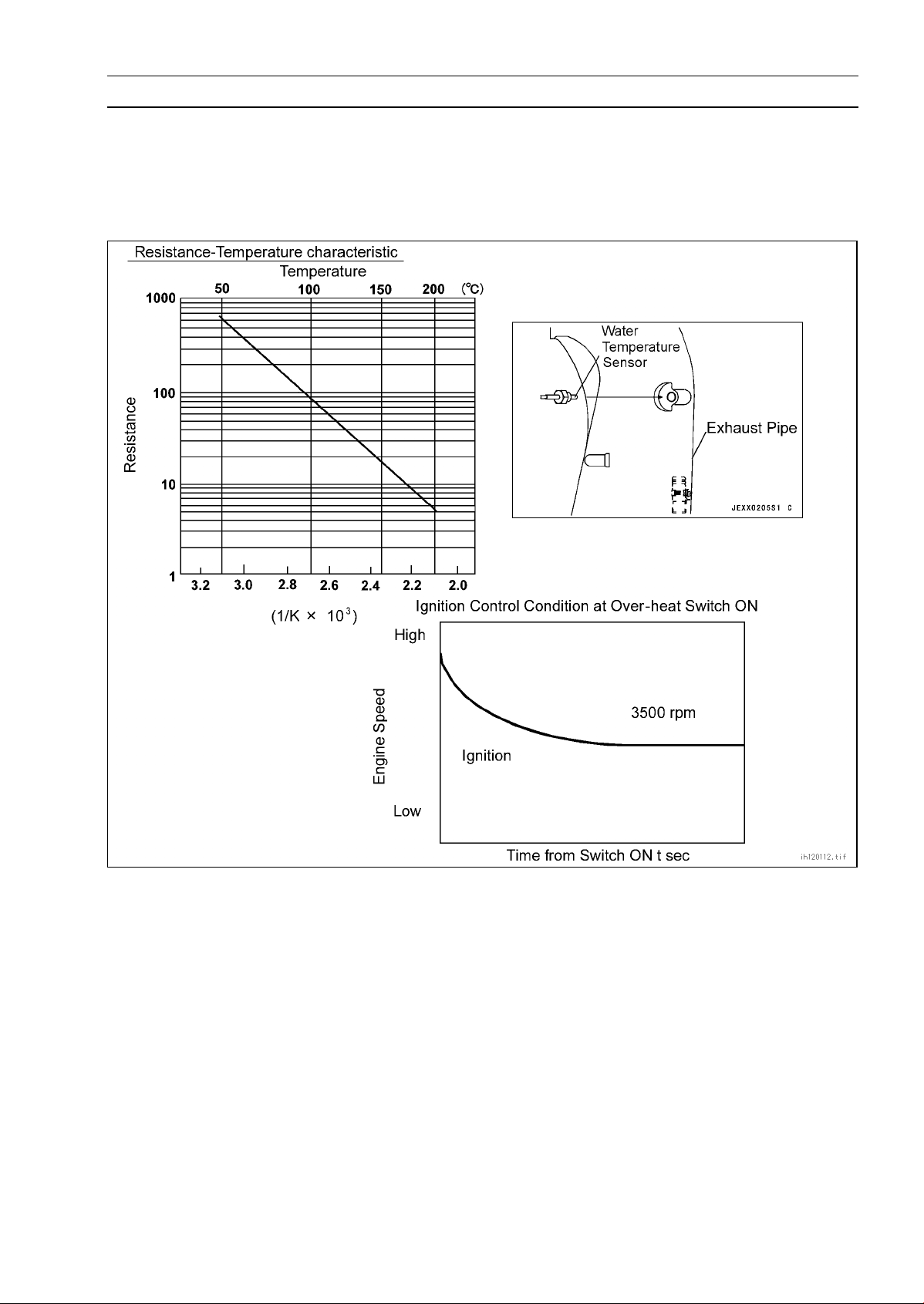
(4) Overheat Control
To protect the engine against overheating, a new, more sensitive heat-sensor constantly monitors
exhaust pipe temperature. When temperature exceeds 90 degrees C or more, the igniter gradually
cuts engine speed to 3 500 rpm where it stays until the temperature is lowered.
Overheat Control
(5) Engine Over-Rev Cut-Off
The igniter stops ignition when engine speed exceeds 7 500 rpm, to protect the engine from damage. The ignition starts again when the engine speed drops below 7 500 rpm.
(6) Engine Tachometer Drive
The electric tachometer is driven by the pulsing signals from the ignitor.
(7) Power Source OFF Function
Three minutes after the engine stops, the igniter shuts off the power source automatically. The
power source turns on again when the starter switch turns on.
(8) Output for Outer Load Function
When the power source of unit turns on, the igniter puts out a voltage equivalent to the battery
voltage on the terminal. This terminal is connected to Trim Switch and Multifunction meter.

1-22 GENERAL INFORMATION
Technical Information-Electrical Parts
1. Engine Starter
The more compact starter features a 1-way clutch with back-torque limiter to prevent starter damage
caused by "kick-back" during starting.
2. Magneto
The exciter coil is eliminated by adopting DC-CDI. Rare earth metal magnets lighten the magneto
and decrease the flywheel effect, improving acceleration response.
JH1200B JH1100A
Diameter (mm) 106 (4.17 in.) 131 (5.16 in.)
Weight (kg) 1.44 (3.18 lb) 2.54 (5.60 lb)
Flywheel effect (kgf·cm²)
16.1 43.0

Unit Conversion Table
GENERAL INFORMATION 1-23
Prefixes fo r Units:
Prefix Symbol Power
mega M ×1000000
kilo k × 1 000
centi c ×0.01
milli m × 0.001
micro µ × 0.000001
Units o f Mass:
kg ×2.205=lb
g × 0.03527 = oz
Units of Volume:
L × 0.2642 =
L × 0.2200 = gal (imp)
L × 1.057 = qt (US)
L × 0.8799 = qt (imp)
L × 2.113 = pint (US)
L × 1.816 =
mL × 0.03381 =
mL × 0.02816 = oz (imp)
mL × 0.06102 = cu in
gal (US)
pint (imp)
oz (US)
Units of Length:
km × 0.6214 = mile
m × 3.281 = ft
mm × 0.03937 = in
Units of Torque:
N·m × 0.1020 = kgf·m
N·m × 0.7376 = ft·lb
N·m × 8.851 = in·lb
kgf·m × 9.807 = N·m
kgf·m × 7.233 = ft·lb
kgf·m × 86.80 = in·lb
Units of Pressure:
kPa × 0.01020 = kgf/cm²
kPa × 0.1450 = psi
kPa × 0.7501 = cmHg
kgf/cm² × 98.07 = kPa
kgf/cm²
cm Hg × 1.333 = kPa
× 14.22 = psi
Units of Speed:
km/h × 0.6214 = mph
Units of Force:
N × 0.1020 = kg
N × 0.2248 = lb
kg ×9.807=N
kg ×2.205=lb
Units of Temperature:
Units of Power:
kW × 1.360 = PS
kW × 1.341 = HP
PS
PS × 0.9863 = HP
× 0.7355 = kW


PERIODIC MAINTENANCE 2-1
Periodic Maintenance
Table of Contents
Torque and Locking Agent...................................................................................................... 2-2
Periodic Maintenance Chart ................................................................................................... 2-5
Specifications ......................................................................................................................... 2-6
Periodic Maintenance Procedure ........................................................................................... 2-7
Fuel System......................................................................................................................... 2-7
Idle Speed Adjustment...................................................................................................... 2-7
Carburetor Synchronization .............................................................................................. 2-7
High Altitude Performance Adjustment ............................................................................. 2-8
Carburetor Cable Adjustment ........................................................................................... 2-8
Oil Pump Cable Adjustment.............................................................................................. 2-9
Choke Cable Adjustment .................................................................................................. 2-9
Fuel Filter Screen Cleaning .............................................................................................. 2-10
Fuel Filter Inspection......................................................................................................... 2-10
Fuel Vent Check Valve Mounting ...................................................................................... 2-10
Fuel Vent Check Valve Inspection .................................................................................... 2-11
Flame Arrester Cleaning ................................................................................................... 2-11
Throttle Shaft Spring Inspection........................................................................................ 2-11
Engine Bottom End.............................................................................................................. 2-11
Coupling Damper Inspection............................................................................................. 2-11
Cooling and Bilge System.................................................................................................... 2-12
Cooling System Flushing .................................................................................................. 2-12
Bilge System Flushing ...................................................................................................... 2-13
Pump and Impeller............................................................................................................... 2-13
Pump and Impeller Inspection .......................................................................................... 2-13
Steering ............................................................................................................................... 2-14
Steering Cable Inspection................................................................................................. 2-14
Steering Cable Lubrication................................................................................................ 2-14
Trim Cable Inspection ....................................................................................................... 2-14
Trim Cable Lubrication...................................................................................................... 2-15
Handlebar Pivot Lubrication.............................................................................................. 2-15
Electrical System ................................................................................................................. 2-16
Battery Charging Condition Inspection ............................................................................. 2-16
Spark P lug Inspection ....................................................................................................... 2-16
Spark P lug Adjustment ..................................................................................................... 2-16
Spark P lug Cleaning ......................................................................................................... 2-17
Lubrication ........................................................................................................................... 2-17
All Hoses, Hose Clamp, Nuts, Bolts and Fasteners Check ................................................. 2-19
Nuts, Bolts, and Fasteners Tightness Inspection.............................................................. 2-19
Hose and Hose Connect Inspection ................................................................................. 2-20
Rubber Strap Inspection ................................................................................................... 2-21
2
 Loading...