

Kawasaki TERYX 750 FI 4×4, TERYX 750 FI 4X4 SPORT, TERYX 750 FI 4X4 LE Assembly & Preparation Manual
TERYX 750 FI 4×4
TERYX 750 FI 4×4 LE
TERYX 750 FI 4×4 SPORT
Recreation Utility Vehicle
Assembly & Preparation
Manual
MilitaryAtvParts.com
* * * MILITARY USE ONLY * * *
* * * MILITARY USE ONLY * * *

MilitaryAtvParts.com
* * * MILITARY USE ONLY * * *
* * * MILITARY USE ONLY * * *
Foreword
In order to ship Kawasaki vehicles as efficiently as possible, they are partially disassembled before crating. Since some of the most
commonly removed parts have a direct bearing on a vehicle’s reliability and safety, conscientious pre-sale assembly and preparation becomes extremely important. Good setup procedures can prevent needless warranty claims
and give customers a greater sense of confidence in Kawasaki and their Kawasaki Dealers.
This Assembly and Preparation Manual explains step by step procedures of the following items for all Kawasaki TERYX 750 FI 4×4,
TERYX 750 FI 4×4 LE and TERYX 750 FI 4×4
SPORT.
1. Crate Handling
2. Uncrating
3. Assembly
4. Preparation
The selling dealer assumes sole responsibility for any unauthorized modifications prior to
sale. Refer to your Service Binder for any Service Bulletins specifying Factory Directed Modifications (Special Claims) which must be performed before the vehicle is ready for sale.
Whenever you see the following symbols
heed their instructions! Always follow safe
operating and maintenance practices.
DANGER
DANGER indicates a hazardous situation which, if not avoided, will result in
death or serious injury.
WARNING
WARNING indicates a hazardous situation which, if not avoided, could result
in death or serious injury.
CAUTION
CAUTION indicates a hazardous situation which, if not avoided, could result
in minor or moderate injury.
NOTICE
NOTICE is used to address practices not
related to personal injury.
NOTE
○This note symbol indicat
es points of particular
interest for more efficient and convenient operation.
Kawasaki Heavy Industries, Ltd. accepts no
liability for any inaccuracies or omissions in this
publication, although every possible measure
has been taken to make it as complete and accurate as possible. All procedures and specifications subject to change without notice.
© 2009 Kawasaki Heavy Industries, Ltd. Aug., 2009
MilitaryAtvParts.com
* * * MILITARY USE ONLY * * *
* * * MILITARY USE ONLY * * *

Table of Contents
Crate Handling .............................................................................. 3
Crate Handling Precautions for RSC (Returnable Steel
Crate)(US Model only) .............................................................. 3
Crate Handling Precautions (Other than US Model) ................... 3
Uncrating ...................................................................................... 4
Opening Crate (US Model only) .................................................. 4
Opening Crate (Other than US Model)........................................ 8
Parts Check ................................................................................. 12
Assembly ...................................................................................... 16
Steering Wheel ............................................................................ 16
Right and Left Bar ....................................................................... 16
Upper and Lower Back Bar ......................................................... 17
Front and Rear Upper Bar ........................................................... 17
Seat Belt ...................................................................................... 19
Windshield (KRF750PAF/RAF Models) ....................................... 21
Cargo Net .................................................................................... 22
Front Guard Cover ...................................................................... 22
French Labels.............................................................................. 22
Preparation ................................................................................... 24
Charged Battery Service (US Model) .......................................... 24
Uncharged Battery Service (Other than US Model) .................... 27
Air Cleaner .................................................................................. 30
Engine Oil .................................................................................... 32
Front Final Gear Case Oil ........................................................... 34
Rear Final Gear Case Oi
l ............................................................
35
Brake Fluid .................................................................................. 36
Brake Pedal ................................................................................. 37
Brake Light Switch
.......................................................................
38
Parking Brake Pedal.................................................................... 38
Steering Wheel ............................................................................ 38
Front Shock Ab
sorber .................................................................
39
Rear Shock Absorber .................................................................. 41
Tire Air Pressures........................................................................ 42
Fuel ............................................................................................. 43
Coolant ........................................................................................ 43
Throttle Pedal .............................................................................. 43
Differ
ential Shift Lever and Cable ................................................
44
Idle Speed Adjustment ................................................................ 44
Headlight Beam ........................................................................... 44
Whee
l Alignment .........................................................................
44
Digital Meter ................................................................................ 46
Fastener Check ........................................................................... 48
S
tandard Torque Table ................................................................50
Test Ride Checklist...................................................................... 50
MilitaryAtvParts.com
* * * MILITARY USE ONLY * * *
* * * MILITARY USE ONLY * * *

CRATE HANDLING 3
Crate Handling
Crate Handling Precautions for
RSC (Returnable Steel Crate)
(US Model only)
Crate Position:
Always place the crate upright on its base.
The crate has been designed to carry the weight
of the vehicle only in that position. The sides
and top of the crate are not strong enough to
act as the base of the crate. If the crate is tilted
very far or set on its end or side, loose parts
may be dislodged and fall inside the crate.
Loading and Unloading Trucks for
RSC:
To load or unload crates, use a fork lift. Never
attempt to unload crates by hand. NEVER
DROP crates off a truck.
Be sure to use the proper handling equipment for safe unloading, storing and stacking
of crated Teryx utility vehicles. The weight
of a large Teryx utility v ehicle plus the RSC
exceeds 860 kg (1,900 lbs.), therefore, t
wo
stacked crates will weigh approximately 1,660
kg (3,660 lbs.).
Use forklifts with at least 5,000 lb. lif
ting
capacity and 60-inch tapered fork blades not
greater than 1-1/2 inches thick. Forklifts should
also be equipped with all safety i
tems, such as
operator cages and fork back rests.
Pulling Crate from Trucks for RSC:
If pulling is necessary to unload from trailer,
please put rope or chain on fork pocket area at
end.
A. Pull chain around fork pocket area.
Stacking Returnable Steel Crates:
The number of crates that may be stacked on
top of one another
depends on the condition
of the crates and your forklift‘s capacity. Teryx
utility vehicle RSCs are designed for integrated
stacking.
Do not stack any other type of crate
or any other materials atop a Teryx RSC.
In any case, do not stack returnable steel
crates m
ore than two high for trucking, and
three high for storage.
Crate Handling Precautions
(Other than US Model)
Crate Pos
ition:
Always place the crate upright on its base.
The crate has been designed to carry the weight
of the v
ehicle only in that position. The sides
and top of the crate are not strong enough to
act as the base of the crate. If the crate is tilted
ver
y far or set on its end or side, loose parts
may be dislodged and fall inside the crate.
MilitaryAtvParts.com
* * * MILITARY USE ONLY * * *
* * * MILITARY USE ONLY * * *
4 UNCRAT
ING
Moving Crated Vehicle:
WARNING
Crate bands are only designed to hold
the cardboard cover in place. If used as
handles they can snap, causing you or
the crate to fall resulting in injury. Do
not move or lift the crate using the crate
bands.
Whenever moving the crate from one place to
anoth
er, use a fork lift or flat bed hand truck. Vehicle crates are too big and heavy to be moved
by hand. While moving a crate, never stand it
on en
d or tip it over on its side. DO NOT DROP
crated vehicles.
Loading and Unloading Trucks:
To load or unload crates, use a fork lift, a lift
-type tail gate, or a ramp. Never unload crates
by hand. NEVER DROP crates off a truck.
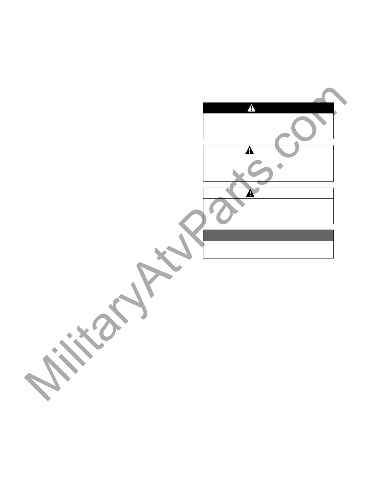
TyingDownCrates:
Always tie down crates when transporting
them. Put the tie downs across the crate at the
crate’s internal vertical braces. Do not use any
hooks on the crate.
Stac
king Disposable Wooden Crates:
The number of crates that may be stacked on
top of one another depends on the condition of
the c
rates more than any other single factor.
Also, take into consideration the weight of the
upper crate(s), the sizes of all the crates in a
sta
ck, and the strength of the bottom crate(s)
base on the type of crate construction (steel,
wood, bracing, etc.).
In a
ny case, do not stack crates more than two
high for trucking, and three high for storage.
Uncrating
Opening Crate (US Model only)
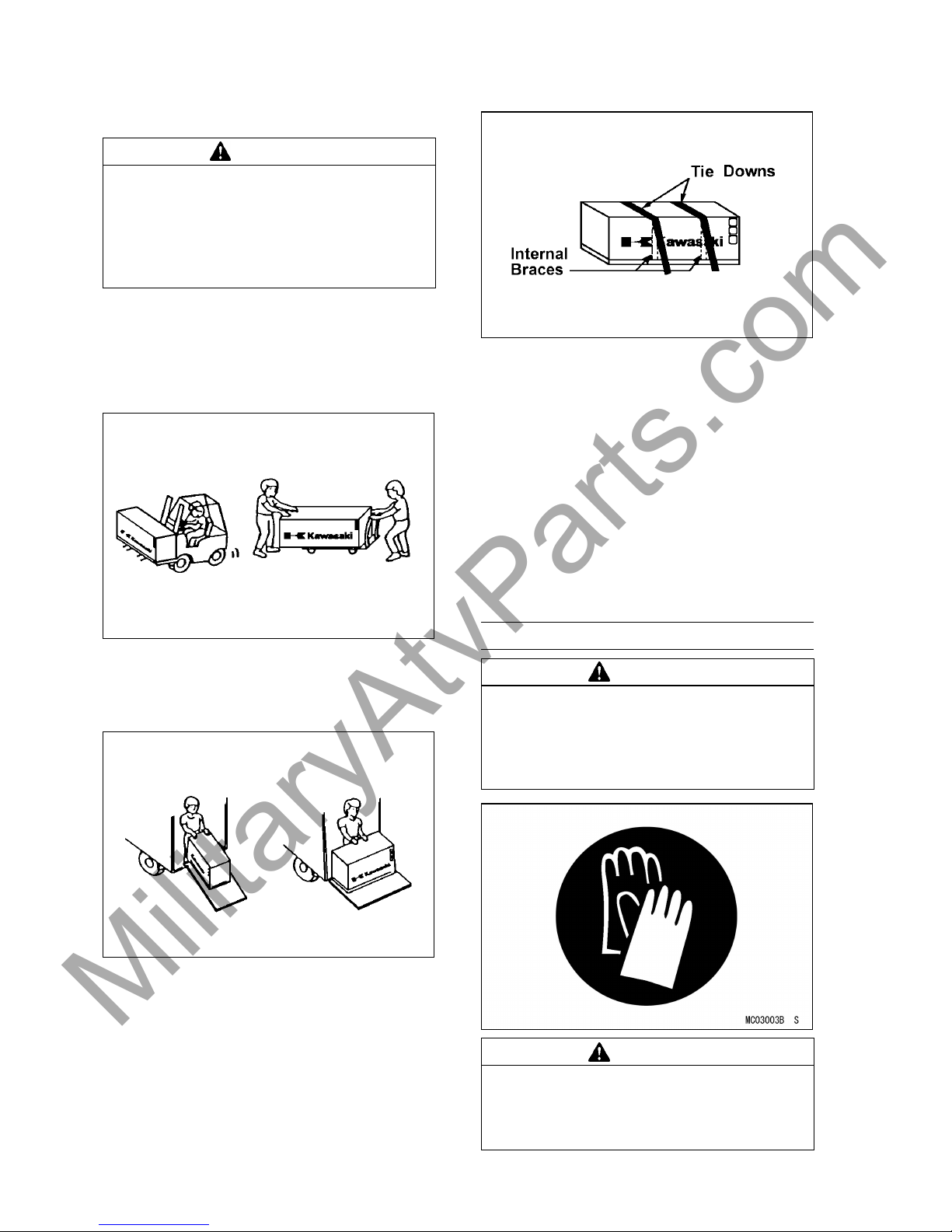
WARNING
Cra
tes have sharp edges and may have
nails or screws that can cause cuts and
injury. Always wear protective gloves,
bo
ots and eye protection when uncrat-
ing to prevent injury.
WARNING
The steel crate panel plates and fasteners have sharp edges. Always wear protective gloves, boots and eye protection
when uncrating to prevent injury.
MilitaryAtvParts.com
* * * MILITARY USE ONLY * * *
* * * MILITARY USE ONLY * * *
UNCRATI
NG 5
•
Clear a space about 6 m (20 ft.) square to
giv
e yourself plenty of space to work.
•
Place the crate upright on its base.
•
Remove the outer cover and inspect the unit
for
concealed damage. If concealed damage
is evident, document the damage as outlined
in the Kawasaki Warranty Policies and Proce
dures Manual before proceeding to uncrate
the unit.
•
Remove the cardboard cover.
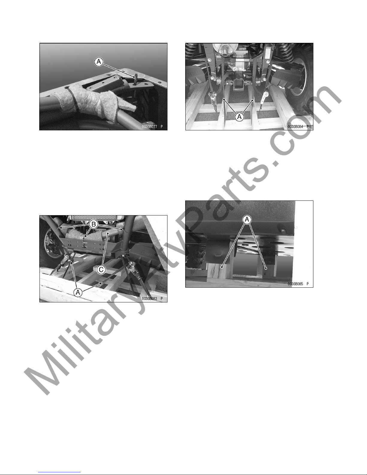
To work efficiently, start work at the rear of the
crate.
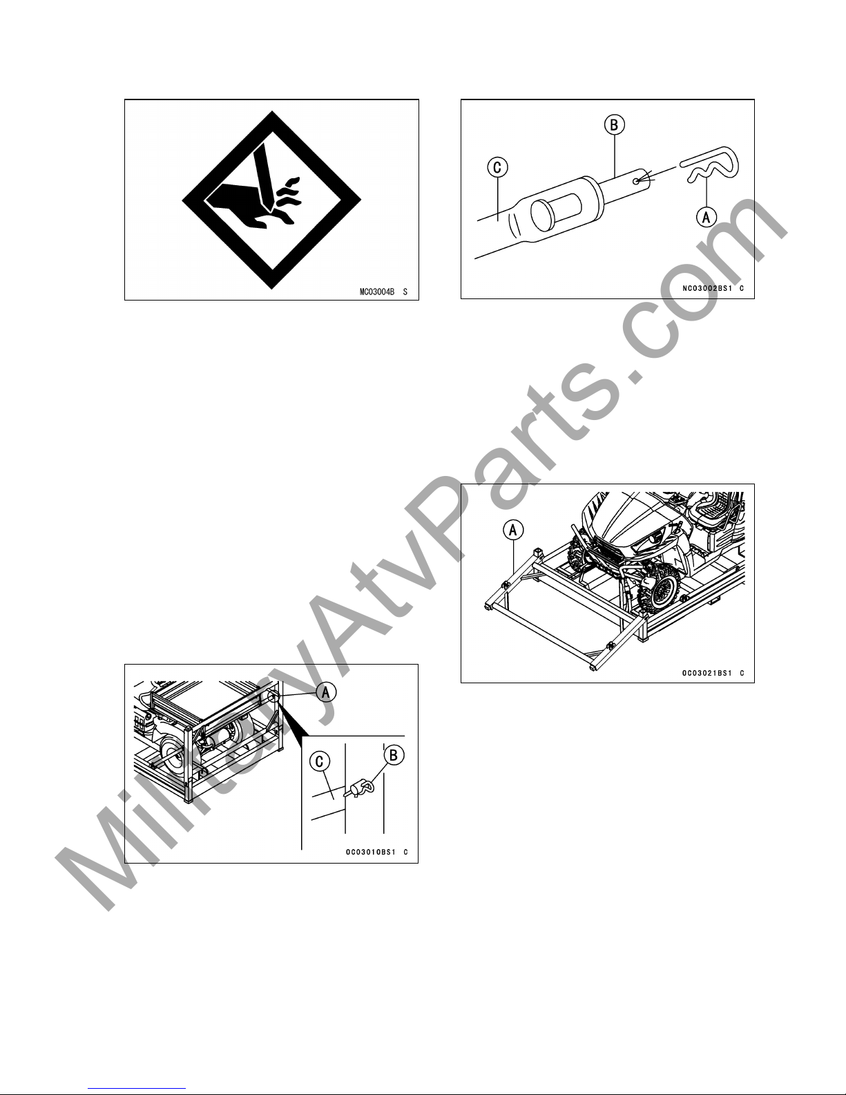
•
Remove the hairpin clips (2), then push out
the clevis pins (2) to disconnect the rear diagon
al braces (2) from the rear upright.
•
Repeat these steps for the front upright.
•
Allow the diagonal braces to pivot out and
d
own to the ground. They remain attached
to the pallet.
A. Rear Upright
B. Hairpin Clip
C. Diagonal Brace
•
Install the hairpin clips (4) back into the braces
for return to KMM.
A. Hairpin Clip
B. Clevis Pin
C. Diagonal Brace
•
Lay down the front and rear uprights. To do
so, lift up on the upright to disengage its sockets from the pallet.
•
Now the upright may be pivoted down to the
ground. (It remains attached to the pallet.) Be
careful not to drop it on anyone.
A. Upright
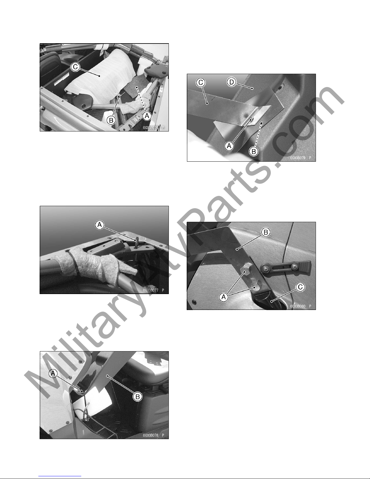
Removing the Right and Left Bar and
Upper Bars and Upper Back B ar
Front Guard Cover and Parts Box Re-
moval
•
Cut the tie-band (1) that retains the front
guard cover and the upper bars, and remove
the front guard cover from the cargo bed.
•
Remove the parts box from the cargo bed.
MilitaryAtvParts.com
* * * MILITARY USE ONLY * * *
* * * MILITARY USE ONLY * * *
6 UNCRAT
ING
A. Parts Box
B. Tie-band
C. Front Guard Cover
Right and Left Bar and Upper Bars and
Upper Back Bar Removal
•
Cut the tie-bands (3) that retain the right and
left bars at cargo bed.
•
Cut the tie-bands of all bars.
A. Tie-bands
Windshield and Sun Top Cover
(KRF750PAF/RAF Model only)
•
Cut the tie-bands (2) that retain the sun top
cover with the windshield, and remove the
windshield from the sun top cover
A. Tie-bands
B. Sun Top Cover
•
Remove the bolts and nuts of right and left
that retain the plate, and remove the sun top
cover from the plate.
•
Discard the bolts and nuts.
A. Bolt (Right)
B. N
ut (Right)
C. Plate (Right)
D. Sun Top Cover
•
Remove the bolts (4) and plates (2) from front
bar, and discard them.
A. Bolts
B. Plates
C. Front Bar
•
Cut the tie-bands (2), and remove the windshield from the sun top cover.
MilitaryAtvParts.com
* * * MILITARY USE ONLY * * *
* * * MILITARY USE ONLY * * *
UNCRATI
NG 7
A. Tie-bands
B. Windshield
C. Sun Top Cover
Removing the Lower Back Bar and
Front Tie-downs Removal
•
Cut the tie-bands (3) that retain the lower back
bar at the front guard, and remove the lower
back bar from the front guard.
•
Remove front tie-downs by opening fully and
disengaging latch. Take care to undo these
evenly as there is heavy tension in the tie
-down.
A. Tie-downs (Front)
B. Tie-bands
C. Lower Back Bar
Rear Tie-down Removal
•
Remove rear tie-downs by opening fully and
disengaging latch. Take care to undo these
evenly as there is heavy tension in the tie
-down.
A. Tie-downs (Rear)
•
Roll the vehicle off the crate base after i nstalling the steering wheel (see “Steering
Wheel” section on page16 in the assembly
chapter).
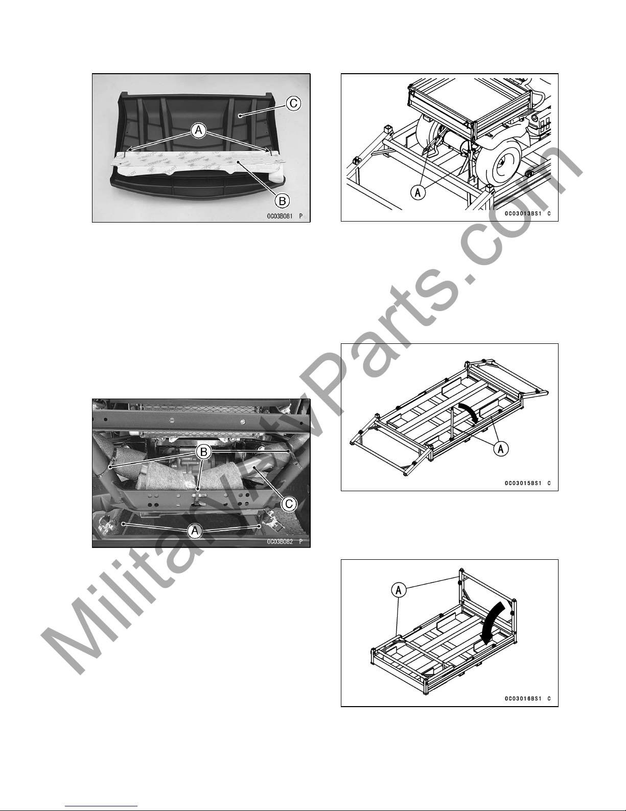
RETURN SHIPMENT
•
Prepare the crate for return shipment.
•
Fold braces in so they lay on the crate pallet.
A. Braces
•
Lift the rear upright to disengage its sockets.
Pivot it down onto the crate pallet. Be careful
not to drop on anyone.
A. Uprights
•
Repeat these steps for the other upright.
MilitaryAtvParts.com
* * * MILITARY USE ONLY * * *
* * * MILITARY USE ONLY * * *
8 UNCRAT
ING
•
The
se items are discarded:
- Outer Cover, Tie-downs (Qty. 4)
Opening Crate
(Other than US Model)
WARNING
Crates have sharp edges and may have
nails or screws that can cause cuts and
injury. Always wear protective gloves,
boots and eye protection when uncrating to prevent injury.
•
Clear a space about 6 m (20 ft.) square to
give yourself plenty of space to work.
•
Place the crate upright on its base.
•
Remove the outer cover and inspect the unit
for concealed damage. If concealed damage
is evident, document the damage as outlined
in the Kawasaki Warranty Policies and Procedures Manual before proceeding to uncrate
the unit.
•
Remove the cardboard cover.
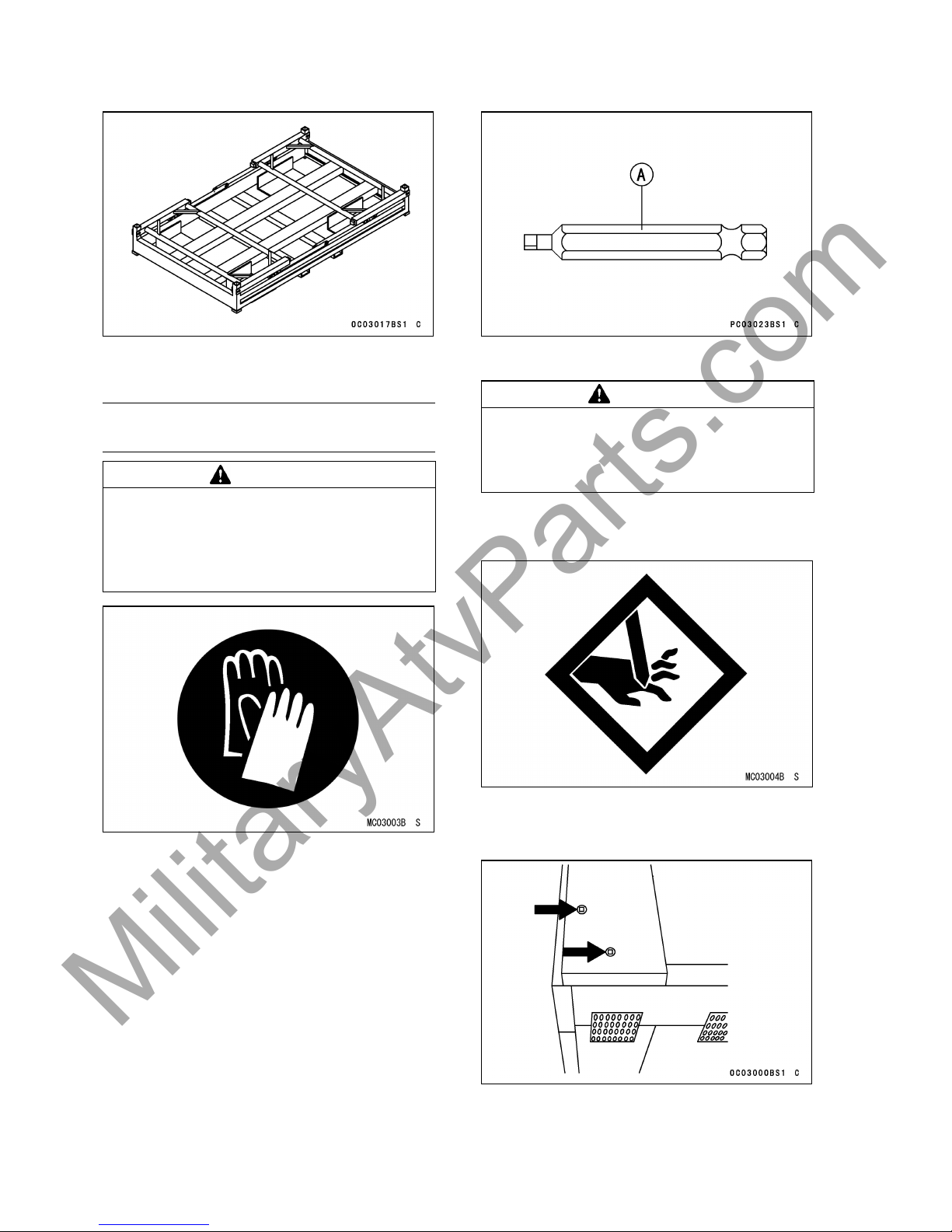
Removing Panels
•
Using a BPS3 square drive bit (ex. IMPORT APEX Square Recess “Power Bits1/4 Hex-size #3” or MAGNA “Insert Bits-size
#3” with quick change holder), remove the
screws from the sides and ends into the top.
A. “Power Bit (APEX)”
WARNING
Staples, nails and other fasteners have
sharp points that can cause injury. Remove or bend into the wood all staples,
nails or other fasteners in the crate base.
•
Take out all the bolts, nuts, screws, and fasteners and remove the top and side panels of
the wood crate.
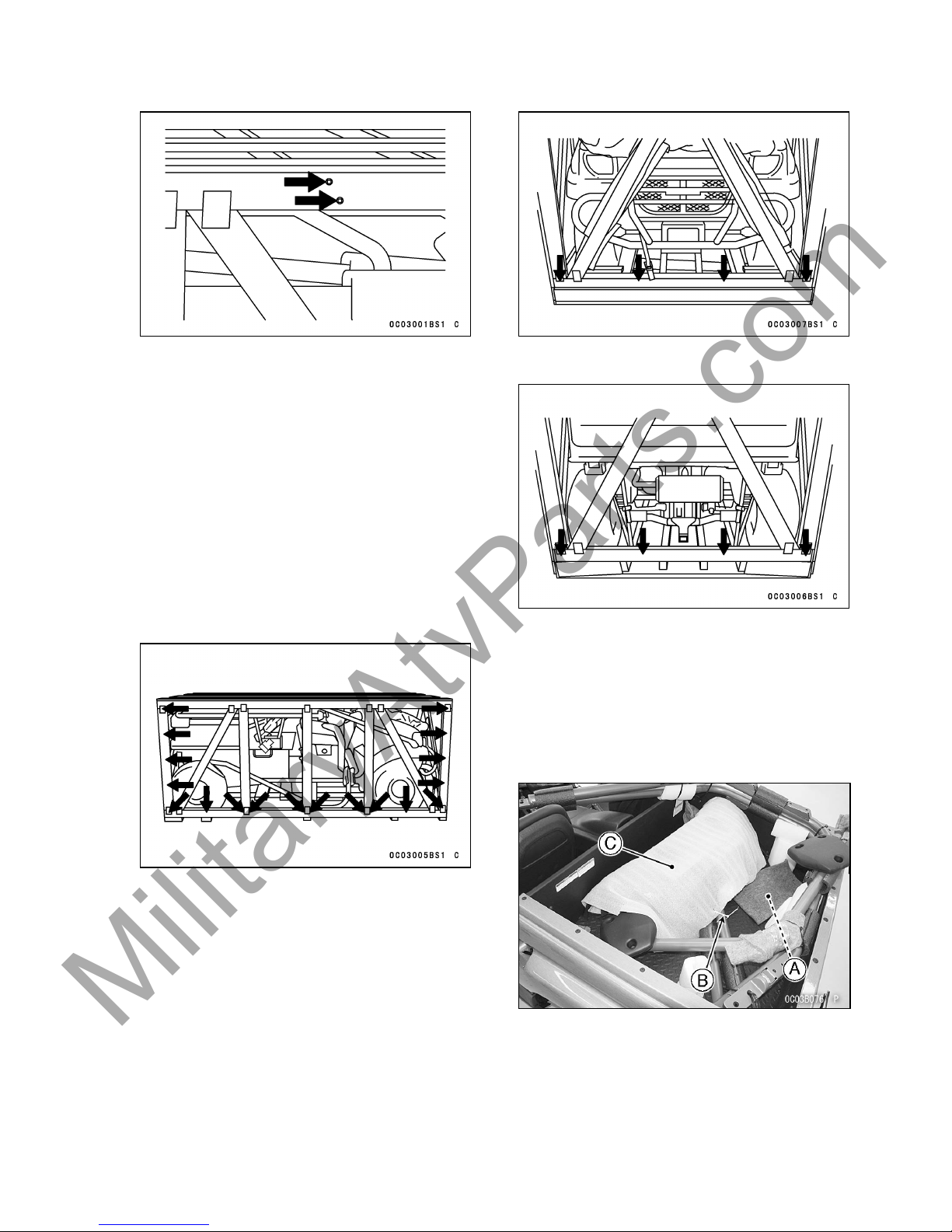
Top Panel Removal
•
Remove the screws from the top crate.
•
There are two screws in every corner.
•
Remove two screws in every cross member.
MilitaryAtvParts.com
* * * MILITARY USE ONLY * * *
* * * MILITARY USE ONLY * * *
UNCRATI
NG 9
•
Top
panel can be lifted from the unit. Have
a second person help to remove this piece
as it can be awkward to handle. Discard this
ass
embly. Take care when letting the screen
and center bar assembly down from the top,
it is heavy and may fall.
Side Panel Removal
•
Remove the (18) screws shown below. The
panel should come loose without excess
force; check for any missed screws if the
panel will not come off easily.
NOTE
○Tr
ying to break the panels off can result in
damage to the unit.
•
Repeat procedure for the other side of the
unit. Discard these panels.
End Panel Removal
•
Remove the (4) screws shown below. The
panel should come loose without excess
force, check for any missed screws if panel
will not come off easily.
NOTE
○Trying to break the panels off can result in
damage to the unit.
•
Rep
eat as above for the rear panel. Discard
these panels.
Removing the Right and Left Bar and
Upper Bars and Upper Back B ar
Front Guard Cover and Parts Box Re-
moval
•
C
ut the tie-band (1) that retains the front
guard cover and the upper bars, and remove
the front guard cover from the cargo bed.
•
R
emove the parts box from the cargo bed.
A. Parts Box
B. Tie-band
C. Front Guard Cover
Right and Left Bar and Upper Bars and
Upper Back Bar Removal
•
Cut the tie-bands (3) that retain the right and
left bars at cargo bed.
•
Cut the tie-bands of all bars.
MilitaryAtvParts.com
* * * MILITARY USE ONLY * * *
* * * MILITARY USE ONLY * * *
10 UNCRA
TING
A. Tie-bands
Removing the Lower Back Bar and
Front Tie-downs Removal
•
Cut the tie-bands (3) that retain the lower back
bar at the front guard, and remove the lower
back bar from the front guard.
•
Remove front tie-downs by opening fully and
disengaging latch. Take care to undo these
evenly as there is heavy tension in the tie
-down.
A. Tie-downs (Front)
B. Tie-bands
C. Lower Back Bar
Rear Tie-down Removal
•
Remove rear tie-downs by opening fully and
disengaging latch. Take care to undo these
evenly as there is heavy tension in the tie
-down.
A. Tie-downs (Rear)
NOTE
○It is important to remove the top panel as the
unit will rise when the tie-downs are undone.
Failure to do so will result in damage to the
unit.
•
Remove the crate base blocks.
A. Crate Base Blocks
•
Roll the vehicle off the crate base after installing the steering wheel (see “Steering
Wheel” section on page16 in the assembly
chapter).
MilitaryAtvParts.com
* * * MILITARY USE ONLY * * *
* * * MILITARY USE ONLY * * *

UNCRATI
NG 11
Dummy Page
MilitaryAtvParts.com
* * * MILITARY USE ONLY * * *
* * * MILITARY USE ONLY * * *
12 UNCRA
TING
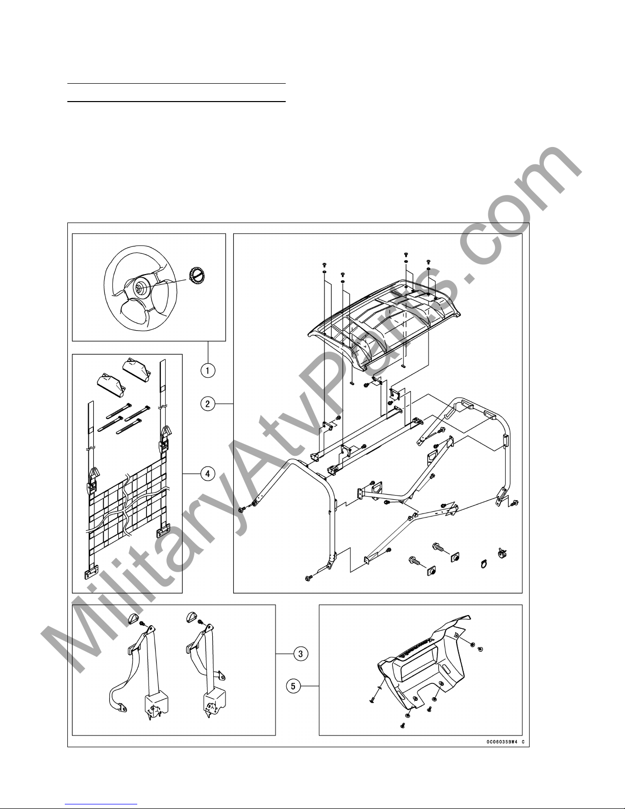
Parts Check
NOTE
○There may be minor differences in appearance between these illustrations and the actual vehicle
parts.
•
Remove the parts and check the crate base and packaged materials carefully for lost parts. Order
any parts that are missing from the crate. Part numbers are provided in the following charts. Check
the parts against the illustrations. In the following charts under Remarks, D = diameter in millimeters,
and L = length in millimeters. In the following charts under Q ty, ( ) = component of assembly parts.
MilitaryAtvParts.com
* * * MILITARY USE ONLY * * *
* * * MILITARY USE ONLY * * *
UNCRATI
NG 13
No. Part Name
Qty
Remarks Part Number
1
Steering Wheel
1 46003-0114
Steering Wheel Cap 1 11065-0171
2 Right B
ar
1 55047-
0022
Left Bar
1 55047-0021
Flanged Bolt, Right and Left Bar 8 D = 14, L = 36 92153-1282
Upper
Back Bar
1 39043
-0005
Lower Back Bar 1 39043-0008
Flanged Bolt, Upper and Lower Back Bar 10 D = 10, L = 14 130CB1014
Front Upper Bar 1 39043-0001
Rear Upper Bar 1 39043-0007
Flanged Bolt, Front and Rear Upper Bar 8 D = 10, L = 14 130CB1014
Clamp, Breather Hose (Fuel Tank) 1 92037-1181
Clamp, Breather Hose (Rear Final Gear Case) 1 92037-1104
Flanged Bolt, Battery Terminal (U.S. Model) 2 D = 6, L = 16 130BA0616
Plate
Nut, Battery Terminal (U.S. Model)
2 D=6 92210-1352
KRF750PAF/RAF Models
Sun Top Cover 1 14091-1770
Pad, Sun Top Cover 4 39156-0479
Screw, Sun Top Cover 8 D = 6, L = 16 92009-1621
Collar, Sun Top Cover 8 D = 16, L = 6.3 92143-1087
Bra
cket, Sun Top Cover
2 11055-0156
Bracket, Sun Top Cover
2 11055–0255
3 Seat Belt with 2 53061-0007
Cover, Seat Belt Upper Bracket (2) 11065-0287
Flanged Bolt, Seat Belt Case, Upper 2 D = 10, L = 16 92153-1740
4 Cargo Net 1 53064-0012
Bu
ckle Cover, Cargo Net
2 14090-1611
Band, Cargo Net
4 L = 123 92072-030
5 Front Guard Cover
Other than KRF750RAF Model 1 55020-0520
KRF750RAF Model Only 1 55020-0521
Screw, Front Guard Cover 2 D = 6, L = 16 92009-1621
T
apping Screw, Front Guard Cover
2 D = 6, L = 16 92009-1166
Collar, Front Guard Cover (Upper and Lower)
4 D = 16, L = 4 92143-1087
MilitaryAtvParts.com
* * * MILITARY USE ONLY * * *
* * * MILITARY USE ONLY * * *
14 UNCRA
TING
No. Part Name Qty Remarks Part Number
6 KRF750PAF/RAF Models
Windshield 1 39154-0047
T
rim, Windshield
1 L
= 450
5
3044-0044
Grommet, Windshield
4 92075-1787
Damper, Windshield 4 92161-0725
Collar, Windshield 4 D = 6.8 × 10 × 14.5 92027-156
Front Bracket, Windshield 4 11055-0913
Rear Bracket, Windshield 4 11055-0914
D
amper, Bracket, Windshield
8 9
2161-0644
Flanged Bolt, Windshield 4 D = 6, L = 35 132BB0635
Washer, Windshield 8 D = 6.5 × 22, L = 1.6 92200-1087
MilitaryAtvParts.com
* * * MILITARY USE ONLY * * *
* * * MILITARY USE ONLY * * *
UNCRATI
NG 15
No. Part Name
Qty
Remarks Part Number
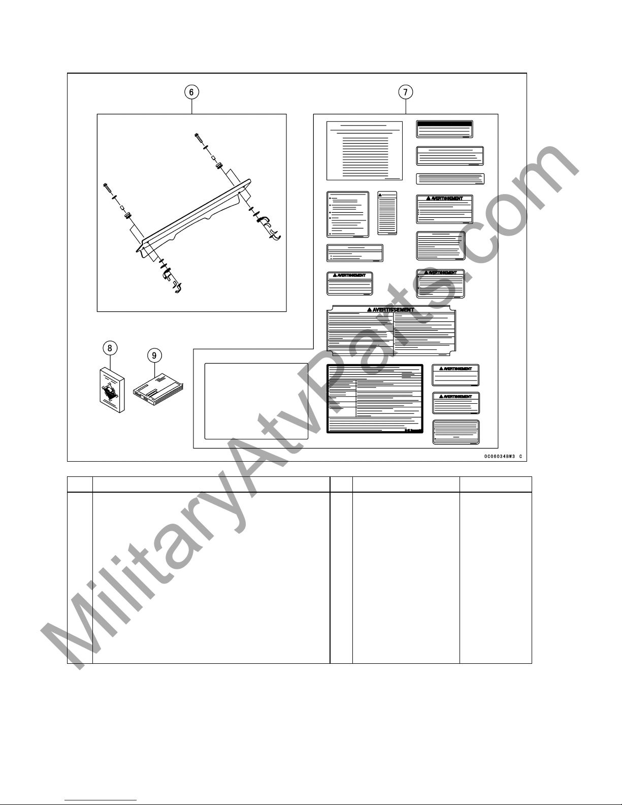
7
French Labels and Instruction for Canadian Model
only
Instruction, Label
KRF750NAF Model only 1 56030-0364
KRF750PAF Model only 1 56030-0365
KRF750RAF Model only 1 56030-0366
KRF750SAF Model only 1 56030-0367
Label, Cargo Bed 1 56071-0147
Label
, Drive Belt Information
1 56033-0305
Label, Parking Brake 1 56030-0330
Label, Specification 1 56053-7519
Label
, Tire/Max.Load
56053-0418
Label, Shifting
1 56071-0129
Label, Protective Cover 1 56070-1271
Label, Warning, General 1 56071-0053
Label, Warning, Trailer Towing 1 56071-0100
Label, Warning, Cargo 1 56071-0112
Label, Warning, Cargo Bed 1 56071-0114
Label, Warning, Cargo Bed 1 56071-7504
Label, Warning, Refueling 1 56071-7505
Labe
l, Vehicle Emission Control Information
KRF750NAF Model only 1 59464-1705
KRF750PAF Model only 1 59464-1706
KRF7
50RAF Model only
1 5946
4-1707
KRF750SAF Model only
1 59464-1708
Label, Air Cleaner Information 1 56033-0348
Cover, Label, Emission Control 1 14092-0127
8 Battery Electrolyte, KMX14-BS (non-U.S. Model) 1 12 V 12 Ah 26022-1040
9 Owner’s Manual 1 –
MilitaryAtvParts.com
* * * MILITARY USE ONLY * * *
* * * MILITARY USE ONLY * * *

16 ASSEM
BLY
Assembly
Steering Wheel
Steering Wheel Installation
•
Remove the steering wheel nut (D = 12) and
the washer (D = 12.1 × 25, L = 1.6) from the
steering shaft.
A. Steering Wheel nut
B. S
teering Wheel Washer
C. Steering Shaft
•
Set the front wheels straight ahead.
•
Mount the steering wheel on the steering
shaft as shown below and reinstall the steering wheel nut (D = 12) and washer (D = 12.1
× 25, L = 1.6) .
•
Tighten the nut to the specified torque.
Torque : 54 N·m (5.5 kgf·m, 40 ft·lb)
A. Washer (D = 12.1 × 25, L = 1.6)
B. Nut (D = 12)
C. Steering Wheel
•
To install the steering wheel cap, insert the
projections of steering wheel into the holders.
A. Steering Wheel Cap
B. Nut (D = 12)
C. Washer (D = 12.1 × 25, L = 1.6)
D. Steering Wheel
NOTICE
Be careful not to puncture a tire with
sharp fasteners when rolling off the vehicle from the crate base.
•
Remove any nails from the crate base that
might not puncture a tire.
•
Roll the vehicle off the crate base.
Right and Left Bar
Seat Removal
•
Remove the seat by pulling up the seat latch
lever located at the front of the seat, and then
pull the seat up and to the front.
A. Seat Latch Lever
NOTE
○It is recommended that the seat should be
installed after completing the steps in the
“Charged Battery Service” or “Uncharged
Battery Service” and “Engine Oil” sections in
the PREPARATION chapter.
MilitaryAtvParts.com
* * * MILITARY USE ONLY * * *
* * * MILITARY USE ONLY * * *

ASSEMBL
Y17
Right and Left Bar Installation
•
With the help of a second person, install one
side bar onto the frame and tighten the front
mounting bolts (D = 14, L = 36) (4) and only
the upper part of the rear mounting bolt (D =
14, L = 36) (2). Install another side bar the
same way.
A. Rear Mounting Bolt (upper part) (D =
14, L = 36)
B. Front Mounting Bolts (D = 14, L = 36)
NOTE
○The lower part of the rear mounting bolt is
tightened with belt bracket later.
Upper and Lower Back Bar
Upper and Lower Back Bar Installation
•
Install the lower back bar and tighten the
mounting bolts (D = 10, L = 14) (4).
A. Lower Back Bar
B.
Bolts (D = 10, L = 14)
•
Install the upper back bar and tighten the
mounting bolts (D = 10, L = 14) (4).
A. Upper Back Bar
B. Bolts (D = 10, L = 14)
•
Connect the upper and lower back bar and
tighten the joint bolts (D = 10, L = 14) (2).
A. Bolts (D = 10, L = 14)
B. Upper Back Bar
C. Lower Back Bar
Front and Rear Upper Bar
Front and Rear Upper Bar Installation
(KRF750NAF/SAF/TAF Models)
•
Install the front and rear upper bars between
the right and left bars with the mounting bolts
(D = 10, L = 14) (8) so that the bracket parts
of the upper bars face upward.
MilitaryAtvParts.com
* * * MILITARY USE ONLY * * *
* * * MILITARY USE ONLY * * *

18 ASSEM
BLY
A. Forward
B. Front Upper Bar
C. Rear Upper Bar
D. Bolts (D = 10, L = 14)
E. Brackets
•
Tighten the right and left bar, upper and lower
back bar, front and rear upper bar mounting
bolts to the specified torque.
Right and Left Bar Mounting Bolt
Torqu e :
98 N·m (10 kgf·m, 72 ft·lb)
Upper and Lower Back Bar Mounting
Bolt Torque:
47 N·m (4.8 kgf·m, 35 ft·lb)
Upper and Lower Back Bar Joint Bolt
Torqu e :
47 N·m (4.8 kgf·m, 35 ft·lb)
Front and Rear Upper Bar Mounting Bolt
Torqu e :
47 N·m (4.8 kgf·m, 35 ft·lb)
Front and Rear Upper Bar and Sun Top
Cover Installation
(KRF750PAF/RAF Models)
•
Install the front upper bar between the right
and left bars so that the bracket parts of
the upper bars face upward and tighten
the bolt (D = 10, L = 14) with the brackets
(11055–0156 and 11055–0255) as shown in
the figure.
A. Front Upper Bar
B. Rear Upper Bar
C. Bolts(D=10,L=14)
D. Bracket (11055-0156)
E. Bracket (11055-0255)
F. Brackets
G. Forward
•
When installing the pads, install them on the
rib of the sun top cover as shown in the figure.
A.
Sun Top Cover
B. Pads
C. 49 mm (1.93 in.)
D.
Installing side for the pads
MilitaryAtvParts.com
* * * MILITARY USE ONLY * * *
* * * MILITARY USE ONLY * * *

ASSEMBL
Y19
•
Install the sun top cover on the brackets with
the screws (D = 6, L = 16) (8) and collars (D
= 16, L = 6.3) (8) and tighten them.
A. Sun Top Cover
B.
Scr
ews (D = 6, L = 16) and Collars (D =
16, L = 6.3)
•
Tighten the right and left bar, upper and lower
back bar, front and rear upper bar mounting
bolts to the specified torque.
Right and Left Bar Mounting Bolt
Torqu e :
98 N·m (10 kgf·m, 72 ft·lb)
Upper a nd Lower Back Bar Mounting
Bolt Torque:
47 N·m (4.8 kgf·m, 35 ft·lb)
Upper and Lower Back Bar Joint Bolt
Torqu e :
47 N·m (4.8 kgf·m, 35 ft·lb)
Front and Rear Upper Bar Mounting Bolt
Torqu e :
47 N·m (4.8 kgf·m, 35 ft·lb)
Breather Hose Installation
•
Install the breather hose (Rear Final Gear
Case) to outside (lower) fitting and install the
clamp.
•
Install the breather hose (Fuel Tank) to inside
(upper) fitting and install the clamp.
NOTE
○Install the two breather hoses to line up as
shown in figure.
A.
Breather Hose (Fuel Tank)
B. Breather Hose (Rear Final Gear Case)
C. Clamp (92037-1181)
D. Clamp (92037-1104)
E. Band
Seat Belt
Seat Belt Installation
•
Install the seat belt bracket to the lower bolt
hole and tighten the right and left bar mounting bolts (D = 14, L = 36) together.
A.
Bolts (D = 14, L = 36)
B. Seat Belt Bracket
•
Tighten the right and left bar mounting bolts
to the specified torque.
Right and Left Bar Mounting Bolt
Torque:
98 N·m (10 kgf·m, 72 ft·lb)
•
Remove the seat belt case mounting bolts (D
= 12, L = 25) (2) and nuts (D = 12) (2) from
the frame.
•
Remove the seat belt case cover from the
seat belt case.
MilitaryAtvParts.com
* * * MILITARY USE ONLY * * *
* * * MILITARY USE ONLY * * *

20 ASSEM
BLY
•
Fit the projection on the recess of the frame
and install the seat belt case as shown in the
figure.
•
Reinstall the seat belt case mounting bolts (D
= 12, L = 25) (2) and nuts (D = 12) (2) and
tighten them together.
A. Bolt (D = 12, L = 25)
B.
Sea
t Belt Case Cover
C. Seat Belt Case
D. Nut (D = 12)
E. Pr
ojection
F. Frame
•
Reinstall the seat belt case cover over the
seat belt case.
A.
Seat Belt Case Cover
B. Seat Belt Case
•
Tighten the seat belt case mounting nut to the
specified torque.
Seat Belt Case Mounting Nut Torque:
47 N·m (4.8 kgf·m, 35 ft·lb)
•
Install the cover to the seat belt bracket.
•
Install the seat belt bracket and tighten the
bolts (D = 10, L = 16) (2) and close the cover.
A.
Bolt (D = 10, L = 16)
B. Cover
C. Seat Belt Upper Bracket
Seat Belt Mounting Bolt Torque:
42 N·m (4.3 kgf·m, 31 ft·lb)
MilitaryAtvParts.com
* * * MILITARY USE ONLY * * *
* * * MILITARY USE ONLY * * *

ASSEMBL
Y21
Windshield (KRF750PAF/RAF Models)
Windsh
ield Installation
•
Install the trim and grommet to the windshield, and install the damper to the front bracket and rear
bracket.
•
Instal
l the brackets on the right and left bars and the windshield with flanged bolt (D = 6, L = 35) (4),
Collar (D = 6.8 × 10 × 14.5) (4) and washers (D = 6.5 × 22, L = 1.6) (8) as shown in the figure and
tighten them.
A. Windshield
B. Trim (L = 450)
C. Collar (D = 6.8 × 10 × 14.5)
D.
Washers (D = 6.5 × 22, L = 1.6)
E.
Grommet
F. Damper (92161-0644)
G. Damper (92161-0725)
H. Front Bracket and Rear Bracket
I. Flanged Bolts (D = 6, L = 35)
J. No gap
K. Front
MilitaryAtvParts.com
* * * MILITARY USE ONLY * * *
* * * MILITARY USE ONLY * * *

22 ASSEM
BLY
Cargo Net
Cargo N
et Installation
•
Remove the bolts to install the cargo net
bracket and tighten the bolts again.
A. Cargo Net Bracket
B. Bolts
C. Cargo Net
•
Install the hook latches and set up cargo net
vertically.
A. Cargo Net
B. Hook Latches
Cargo Net Buckle Cover Installation
•
Install the cargo net buckle c over as shown in
figure.
•
Install the band to both ends of the cargo net
buckle covers and tighten them.
NOTE
○Install the cover with the net tension adjusting
buckle and store the loose net strap into the
cargo net buckle cover.
A.
Cargo Net Buckle Cover
B. Bands
C.
Net Tension Adjusting Buckle
Front Guard Cover
Front Guard Cover Installation
•
Install the front guard cover onto the front
guard.
•
Tighten the tapping screws (D = 6, L = 16) (2)
and collars (D = 16, L = 4) (2).
•
Tighten the screws (D = 6, L = 16) (2) and
collars (D = 6, L = 16) (2).
A.
Front Guard Cover
B.
Tapping Screw (D = 6, L = 16) and
Collar (D = 16, L = 4)
C. Screw (D = 6, L = 16) and Collar (D =
16, L = 4)
French Labels
For Canadian Model:
NOTE
○Apply the French labels over the English la-
bels on the unit when required.
MilitaryAtvParts.com
* * * MILITARY USE ONLY * * *
* * * MILITARY USE ONLY * * *

ASSEMBL
Y23
•
Wipe off any oil or grease from the English
labels. Refer to the following photographs in
the l abel locations.
•
Peel each French label off the backing sheet
and apply it over the English label.
1. General Warning (56071-0053)
2. Shifting Caution (56071-0129)
3. Parking Brake (56030-0330)
4. Refueling Warning (56071-7505)
5. Cargo Bed Warning (56071-7504)
6. Cargo Bed Notice (56071-0147)
7. ROPS Specification (56053-7519)
8. Cargo Warning (56071-0112)
9. Tire Information (56053-0418)
10. Cargo Bed Warning (56071-0114)
11. Protective Cover Warning (56070-1271)
12. Air Cleaner Information (56033-0348)
13. Drive Belt Information (56033-0305)
14. Trailer Towing Warning (56071-0100)
MilitaryAtvParts.com
* * * MILITARY USE ONLY * * *
* * * MILITARY USE ONLY * * *

24 PREPA
RATION
15. Vehicle Emission Control Information
(KRF750NAF Model 59464-1705)
(KRF750PAF Model 59464-1706)
(KRF750RAF Model 59464-1707)
(KRF750SAF Model 59464-1708)
16. Cover, Label, Emission Control (14092
-0127)
Preparation
Charged Battery Service (US
Model)
Pre-filled, Pre-charged Battery
The battery used in this RUV is a pre-filled, pre
-charged, sealed battery, eliminating the need
for dealers to prepare the battery by filling it with
electrolyte. However, dealers should still check
each battery’s state of charge periodically to be
sure it meets the minimum 12.6 volt specification and charge it to 100% state of charge during Assembly & Preparation.
The new battery is built to automotive industry
standards and should hold a charge of 75% or
above for approximately six months at 72-77°F.
Because the battery will discharge at different
rates based on varying conditions, it is recommended that it be checked every three months
on any inventory unit.
Battery Charging Condition Inspection
Battery charging condition can be checked by
measuring battery terminal voltage.
The battery is located under the left end of the
driver’s seat.
•
Remove the protective caps on the battery
terminals and discard them.
A. Protective Caps
•
Measure the battery terminal voltage.
NOTE
○Measure with a digital voltmeter that can be
read to at least one decimal place voltage.
Battery Terminal Voltage
Standard: 12.6 V or more
•
If the reading is above the specification refreshing charge is not required. Go on to the
next step.
A. Voltmeter
•
If the reading is below the specification refreshing charge is required. See the “Battery
Removal” and “Refreshing Charge” section.
MilitaryAtvParts.com
* * * MILITARY USE ONLY * * *
* * * MILITARY USE ONLY * * *

PREPARA
TION 25
Battery Installation
•
TurnthemainswitchOFF.
•
Route the battery cables as shown, and first
connect the red protective capped positive
cable to the battery positive terminal (+), then
connect the negative c able to the negative
terminal (–).
•
Put a light coat of grease on the terminals to
prevent corrosion.
A.
Protective Cap
B. Positive Cable (+)
C. Negative Cable (–)
D.
Battery Holder
E. Battery
•
Cover the positive terminal (+) with its red protective cap.
Battery Removal
•
Loosen the bolts to remove the battery holder.
•
Remove the battery holder and take the battery out of the battery case. Be careful that
any rubber dampers are not pulled out of position.
A. Bolts
B. Battery Holder
C. Battery
Battery Specifications
Battery Capacity 12 V 14 Ah
Batter
yP/No.
26012-0107
Refreshing Charge
DANGER
Batteries produce an explosive gas mixture of hydrogen and oxygen that can
cause serious injury and burns if ignited.
Keep the battery away from sparks and
open flames during charging. When
using a battery charger, connect the
battery to the charger before turning on
the charger. This procedure prevents
sparks at the battery terminals which
could ignite any battery gases.
NOTICE
Always remove the battery from the
vehicle for charging. If the battery is
charged while still installed, battery
electrolyte may spill and corrode the
frame or other parts of the vehicle.
Charging the battery at a rate higher than
specified may ruin the battery. Charging
at a high rate causes excess heat which
can warp the plates and cause internal
shorting.
Higher-than-normal charging rates also
cause the plates to shed active material.
Deposits will accumulate, and can cause
internal shorting.
If the temperature of the electrolyte
rises above 45°C (113°F) during charging, reduce the charging rate to lower
the temperature, and increase charging
time proportionately.
NOTE
○Neverattempttochargeafrozenbattery.
○Allow it to warm up to room temperature be-
fore charging.
○Never leave a battery on a trickle charger
longer than 48 hours. Serious damage to the
battery will occur.
WARNING
This battery is sealed battery type.
Never remove seal sheet or cap even at
charging. Never add water. Charge with
current and time as stated below.
MilitaryAtvParts.com
* * * MILITARY USE ONLY * * *
* * * MILITARY USE ONLY * * *

26 PREPA
RATION
A. Seal Sheet or Cap
•
Refer to the Battery Charging Time Table for
the charging.
•
Determine battery condition after charging.
○Determine the condition of the battery 30 min-
utes after completion of the charge by measuring the terminal voltage according to the
table below.
Criteria Judgement
12.6 V or higher Good
12.0 ∼ 12.6 V
Charge insufficient
→ Recharge
12.0 V or lower
Unserviceable
→ Replace
Battery Installation
•
TurnthemainswitchOFF.
•
Check that the rubber dampers on the battery
holder and the battery case are properly in
place.
A. Battery Case Damper
A.
Battery Holder Damper
•
Put the battery in the battery case.
•
Reinstall the nuts, battery holder rod and battery in the reverse of removal.
•
Be sure not to pinch the positive cable with
the battery holder.
•
Route the battery cables as shown, and first
connect the red protective capped positive
cable to the battery positive terminal (+), then
connect the negative cable to the negative
terminal (–).
•
Put a light coat of grease on the terminals to
prevent corrosion.
•
Cover the positive terminal (+) with its red protective cap.
MilitaryAtvParts.com
* * * MILITARY USE ONLY * * *
* * * MILITARY USE ONLY * * *

PREPARA
TION 27
A. Protective Cap
B. Positive Cable (+)
C. Negative Cable (–)
D. Battery Holder
E. Battery
Uncharged Battery Service (Other
than US Model)
Conventional Battery Type
A. Battery
The battery used in this RUV is a conventional
type. Follow the procedure for activating a new
battery to ensure the best possible battery performance.
Activating the battery requires two steps,
filling the battery with electrolyte, and charging.
Read the Battery Safety label shown below and
following procedures carefully before battery
activation.
NOTICE
Incorrect Battery Activation will reduce
battery performance and service life. Be
sure to strictly follow the Battery Service
instructions in this Manual.
DANGER
Heed the battery safety label shown
here.
•
Make sure to use the electrolyte packed in the
crate with the unit.
•
Mak
e sure that the model name of the electrolyte container matches the model name of
the battery. These names must be the same.
Battery Model Name for
KRF750NAF/PAF/RAF/SAF:
KMX14-BS
A. Model Name of the Electrolyte
B. Model Name of the Battery
Battery Removal
•
Loosen the nuts to remove the battery holder.
•
Remove the battery holder and take the battery out of the battery case. Be careful that
any rubber dampers are not pulled out of position.
MilitaryAtvParts.com
* * * MILITARY USE ONLY * * *
* * * MILITARY USE ONLY * * *

28 PREPA
RATION
A. Bolts
B. Battery Holder
C. Battery
Battery Specifications
Make Yuasa
Battery Type KMX14-BS
Battery Capacity 12 V 12 Ah
Electrolyte Capacity 0.69 L
Battery/Electrolyte Set P/No.
26012-1414
Battery Activation
Filling the Battery with Electrolyte
NOTICE
Do not remove the aluminum sealing
sheet [A] from the filler ports [B] until
just prior to use. Be sure to use the dedicated electrolyte container for correct
electrolyte volume.
•
Place the battery on a level surface.
•
Check to see that the sealing sheet [A] has no
peeling, tears, or holes in it.
•
Remove the sealing sheet [A].
NOTE
○The battery is vacuum sealed. If the sealing
sheet has leaked air into the battery, it may
require a longer initial charge.
•
Remove the electrolyte container from the
vinyl bag.
•
Detach the strip of caps [A] from the container
and set aside, these will be used later to seal
the battery.
NOTE
○Do not
pierce or otherwise open the sealed
cells [B] of the electrolyte container. Do not
attempt to separate individual cells.
•
Place the electrolyte container upside down
with the six sealed cells into the filler ports
of the battery. Hold the container level, push
down to break the seals of all six cells. You
will see air bubbles rising into each cell as the
ports fill.
NOTE
○D
o not tilt the electrolyte container.
•
Check the electrolyte flow.
•
If no air bubbles [A] are coming up from the
filler ports, or if the container cells have not
emptied completely, tap the container [B] a
few times.
MilitaryAtvParts.com
* * * MILITARY USE ONLY * * *
* * * MILITARY USE ONLY * * *

PREPARA
TION 29
•
Kee
p the container in place for 20 minutes or
more. Don’t remove the container from the
battery until it’s empty, the battery requires all
the
electrolyte from the container for proper
operation.
NOTICE
Removal of the container before it is
completely empty can shorten the service life of the battery. Do not remove
the electrolyte container until it is completely empty and 20 minutes have
elapsed.
•
Gently remove the container from the battery.
•
Let the battery sit for 30 minutes prior to
charging to allow the electrolyte to permeate
into the plates for optimum performance.
NOTE
○Charging the battery immediately after filling
can shorten service life. Let the battery sit for
at least 30 minutes after filling.
Initial Charge
•
Place the strip of caps loosely over the filler
ports.
A. Strip
•
Newly activated sealed batteries require an
initial charge.
Standard Charge:
1.2 A × 5 ∼ 10 hours
•
If using a recommended battery charger, follow the charger’s instructions for newly activated sealed battery.
Kawasaki-recommended chargers:
Optimate III
Yuasa
1.5 Amp Automatic Charger
Battery Mate 150-9
•
If the above chargers are not available, use
equivalent one.
NOTE
○Charging rates will vary depending on how
long the battery has been stored, temperature, and the type of charger used. Let battery
sit 30 minutes after initial charge, then check
voltage using a voltmeter. If it is not at least
12.8 volts, repeat charging cycle.
•
After charging is completed, press down
firmly with both hands to seat the strip of
caps [A] into the battery (don’t pound or hammer). When properly installed, the strip of
caps will be level with the top of the battery.
NOTICE
Once the strip of caps [A] is installed
onto the battery, never remove the caps,
nor add water or electrolyte to the battery.
NOTE
○To ensure maximum battery life and customer
satisfaction, it is recommended the battery be
load tested at three times its amp-hour rating
for 15 seconds.
Re-check voltage and if less than 12.8 volts
repeat the charging cycle and load test. If still
below 12.8 volts the battery is defective.
MilitaryAtvParts.com
* * * MILITARY USE ONLY * * *
* * * MILITARY USE ONLY * * *

30 PREPA
RATION
Battery Installation
NOTE
○The procedure of the installation is the same
as the a
bove “Charged Battery Service (US
Model)”.
•
TurnthemainswitchOFF.
•
Check that the rubber dampers on the battery
holder and the battery case are properly in
place.
•
Put the battery in the battery case.
•
Reinstall the nuts, battery holder rod and battery in the reverse of removal.
•
Route the battery cables as shown, and first
connect the red protective capped positive
cable to the battery positive terminal (+), then
connect the negative cable to the negative
terminal (–).
•
Put a light coat of grease on the terminals to
prevent corrosion.
•
Cover the positive terminal (+) with its red protective cap.
A. Battery
B. Holder
C
. Positive Cable (+)
D. Negative Cable (–)
Air Cleaner
Air Cleaner Element Inspection
The foam air cleaner element on RUV models
is oiled prior to shipping. However, over time
the filter will dry and filtration performance will
diminish.
•
Release the rivets and remove the air cleaner
top cover.
A. Ai
r Cleaner Top Cover
B. Rivets
•
Pull up the snaps and remove the air cleaner
housing cap.
A. Air Cleaner Housing Cap
B. Snaps
•
Inspect the foam air cleaner element for
proper oiling.
•
If the foam element is dry, remove the screw
(D = 6, L = 18) and pull out the foam air
cleaner element and the element frame from
the air cleaner housing.
A. Screw (D = 6, L = 18)
B. Foam Element
C. Air Cleaner Housing
MilitaryAtvParts.com
* * * MILITARY USE ONLY * * *
* * * MILITARY USE ONLY * * *

PREPARA
TION 31
•
Remove the foam element cover screw (D =
6, L = 18) and foam element cover.
•
Take the foam element off the element frame.
A. Screw (D = 6, L = 18)
B. Foam Element Cover
•
Saturate the foam air cleaner element with a
high-quality foam air filter oil (ex. Kawachem
“Foam Filter Oil”, Bel Ray “Foam Filter Oil”,
Maxima “FFT Foam Filter Treatment”, or
equivalent cohesive type) and make sure
that the oil is evenly applied throughout the
foam air cleaner element. Squeeze out the
excess oil, but do not wring the foam air
cleaner element as this could cause tearing.
In this case, too much oil is better than too
little. Finally pat the inside of the foam air
cleaner element with a clean towel to remove
any excess oil.
A. Clean Towel
•
Install the element onto its element frame,
and coat the element lip and lip seat with a
thick layer of all-purpose grease to assure a
complete seal.
NOTE
○Be sure that the edge of the foam element fits
completely in the groove and does not rest
on the edge of the element holder or become
folded in the groove as shown in the illustrations.
A. Element Holder
B. Foam Element
•
Reinstall the element cover to the specified
torque so that the wider side faces projection
of the element frame and fit the slits onto the
projections.
Torque : 4.5 N·m (0.46 kgf·m, 40 in·lb)
A. Foam Element
B. Element Frame
C. Element Cover
D. Wider Side
E. Projection
F. Slits
G. Projections
•
Install the foam element into the air cleaner
housing so that the wider side faces up, and
insert tabs and both sides of the element
cover into the holder of the air cleaner housing.
MilitaryAtvParts.com
* * * MILITARY USE ONLY * * *
* * * MILITARY USE ONLY * * *

32 PREPA
RATION
A. Foam Element
B. Air Cleaner Housing
C. Wi
der Side Faces
D. Tabs
E. Holder
•
Tighten the screw to the specified torque.
Torque : 4.5 N·m (0.46 kgf·m, 40 in·lb)
•
Insert tabs of air cleaner top cover into the
slits of the engine upper cover.
A. Slits
B. Tabs
C. Air Cleaner Top Cover
•
Reinstall the air cleaner top cover, air cleaner
element and the air cleaner housing cap in the
reverse of removal
•
Install the rivets to the air cleaner top cover.
Engine Oil
Engine Oil Level Inspection
DANGER
Exhaust gas contains carbon monoxide,
a colorless, odorless poisonous gas. Inhaling carbon monoxide can cause serious brain injury or death. DO NOT run
the engine in enclosed areas. Operate
only in a well-ventilated area.
NOTE
○This vehicle’s engine is filled with 10W-30 oil
from th
e factory. DO NOT DRAIN and refill
the crankcase before use. Check oil level and
drain plug tightness.
Engine Oil Drain Plug Torque:
20 N·m (2.0 kgf·m, 15 ft·lb)
•
Remove the bottom guard and bottom guard
bolts.
A. Bottom Guard Bolts
B. Bottom Guard
A. Oil Drain Plug
•
Park the vehicle so that it is level, both side-to
-side and front-to-rear.
•
Before starting the engine, check that the engine has oil.
•
To remove the protective cover, pull out the
quick rivets by prying the suitable tool onto the
center part of the rivet. Remove the cover.
MilitaryAtvParts.com
* * * MILITARY USE ONLY * * *
* * * MILITARY USE ONLY * * *

PREPARA
TION 33
A. Quick Rivets
B. Protective Cover
•
Unscrew the oil filler plug on the lower left side
of the engine and wipe the dipstick dry. Then
screw it in again. Unscrew the plug and check
that the engine has oil.
A. Oil Filler Plug
•
When installing the plug, be sure the O-ring is
in place, and screw the plug in finger tight.
NOTICE
If the engine is run without oil, it will be
severely damaged.
•
Start the engine and run it for several minutes
at idle speed. Stop the engine, then wait several minutes until the oil settles.
•
Unscrew the oil filler plug, wipe its dipstick dry,
and screw it in again.
•
Unscrew the plug and check the oil level. The
oil level should be between the H (High) and
L (Low) lines on the dipstick.
A. Dipstick
B. H (High) line
C. L (Low) line
•
If the oil level is too high, remove the excess
oil through the oil filler opening using a syringe
or some other suitable device.
•
If the oil level is too low, add the oil to reach
the correct level.
•
Screw the plug in finger tight.
Recommended Engine Oil
Type: API SG, SH, SJ, SL or SM with
JASO MA, MA1 or MA2 class
Viscosity: SAE 10W-40
Capacity: 2.4 L (2.5 US qt)
[when filter is not removed]
2.5L(2.6USqt)
[when filter is removed]
Although 10W-40 engine oil is the recommended oil for most conditions, the oil viscosity
may need to be changed to accommodate
atmospheric conditions in your riding area.
•
Install the protective cover, and insert the two
quick rivets.
MilitaryAtvParts.com
* * * MILITARY USE ONLY * * *
* * * MILITARY USE ONLY * * *

34 PREPA
RATION
A. Quick Rivets
B. Protective Cover
•
To install the seat, insert the projections at the
rear of the seat into the seat holders and push
down on the seat at the front. The seat lock
clicks.
WARNING
A loose seat can cause the operator
or passenger to lose control or fall out
of the vehicle, causing severe injury
or death. Be sure the seat is securely
latched.
A. Seat
B. Projections
C. Seat Holders
Front Final Gear Case Oil
Front Final Gear Case Oil Level Inspec-
tion
•
With the vehicle level front-to-rear and side-to
-side, remove the filler cap from the front final
gear case.
A. Front Final Gear Case
B. Filler Cap
C. Front Axle Shaft
NOTICE
Be careful not to allow any dirt or foreign materials to enter the front final
gear case.
•
Check the oil level. The oil level should come
to the bottom thread of the filler opening. If
it is insufficient, add oil through the oil filler
opening as necessary.
A. Front Final Gear Case
B. Filler Opening
C. Bottom Thread
•
Install the filler cap.
Front Final Gear Case Oil
(Equivalent to engine oil)
Type: API SG, SH, SJ, SL or SM with
JASO MA, MA1 or MA2 class
Viscosity:
SAE 10W-40
Capacity: 0.70 L (0.74 US qt)
Although 10W-40 engine oil is the recommended oil for most conditions, the oil viscosity
may need to be changed to accommodate
atmospheric conditions in your riding area.
MilitaryAtvParts.com
* * * MILITARY USE ONLY * * *
* * * MILITARY USE ONLY * * *

PREPARA
TION 35
Oil Filler Cap Torque:
29 N·m (3.0 kgf·m, 21 ft·lb)
Rear Final Gear Case Oil
Rear Final Gear Case Oil Level Inspec-
tion
•
With the vehicle level front-to-rear and side-to
-side, remove the filler cap from the rear final
gear case.
A. Rear Final Gear Case
B. Filler Cap
NOTICE
Be careful not to allow any dirt or foreign materials to enter the rear final gear
case.
NOTE
○Front and rear final gear cases use different
types o
f oils. Use the specified type and brand
of oil in each final gear case.
Rear Final Gear Case Oil
Type: Mobil Fluid 424,
CITGO TRANSGARD
TRACTOR HYDRAULIC FLUID,
Exxon Hydraul 560
Capacity: 1.0 L (1.06 US qt)
NOTE
○Do not use front final gear case oil into the
rear final gear case. Use only the specified oil.
The rear final gear case contains brake plates
which require a special oil type. Also the two
different oil types for the rear gear case oil
must not be mixed in use.
•
Check the oil level. The oil level should come
to the bottom thread of the filler opening. If
it is insufficient, add oil through the oil filler
opening as necessary.
A. Rear Final Gear Case
B. Filler Opening
C. Bottom Thread
•
Install the filler cap.
Oil Filler Cap Torque:
29 N·m (3.0 kgf·m, 21 ft·lb)
MilitaryAtvParts.com
* * * MILITARY USE ONLY * * *
* * * MILITARY USE ONLY * * *

36 PREPA
RATION
Brake Fluid
Brake F
luid Level Inspection
WARNING
Brake fluid that is contaminated by
moisture or dirt, mixed or contains air
has a lower boiling point and can cause
the brake to be ineffective or fail, and it
may cause rubber parts to deterioate,
resulting in an accident causing injury
or death. Never reuse old brake fluid.
Do not use fluid from a container that
has been left unsealed or that has been
open for a long time. Do not mix two
types and brands of fluid for use in the
brake. Don’t leave the reservoir cap off
for any length of time to avoid moisture
contamination of the fluid. Don’t add or
change the fluid in the rain or when a
strong wind is blowing.
NOTICE
Brake fluid quickly ruins painted surfaces. Wipe up any spilled fluid immediately.
•
Wi
th the vehicle on level ground, release the
rubber bands on both sides.
•
Clear the four hook portions from the slots and
li
ft the front cargo hood up.
A. Front Cargo Hood
B. Band
C. Hook Portions
•
Support the hood in the tilted position with the
supporting rod.
A. Front Cargo Hood
B. Supporting Rod
•
Check that the fluid level in the reservoir is
between the upper (MAX) and lower (MIN)
level lines.
A. Brake Fluid Reservoir
B. Upper Level Line (MAX)
C. Lower Level Line (MIN)
•
If the fluid level in the reservoir is lower than
the lower level line, check for fluid leaks in the
front brake lines and fill the reservoir.
•
Remove the brake fluid reservoir cap.
•
Fill the reservoir to the upper level line with
DOT3 brake fluid, and reinstall the reservoir
cap and tighten it to the specified torque.
Torque : 3.4 N·m (0.35 kgf·m, 30 in·lb)
MilitaryAtvParts.com
* * * MILITARY USE ONLY * * *
* * * MILITARY USE ONLY * * *

PREPARA
TION 37
A. Reservoir Cap
•
Operate the brake pedal several times.
•
If it feels spongy, there might be air in the
brake lines.
•
If necessary, bleed the air in the brake line.
•
Also check for fluid leakage around the fittings.
BrakeLineAirBleeding
•
With the front brake reservoir horizontal, remove the front brake reservoir cap and diaphragm, and check that there is plenty of
fluid in the reservoir.
NOTE
○The fluid level must be checked several times
during the bleeding operation and replenished
as necessary. If the fluid in the reservoir runs
completely out any time during bleeding, the
bleeding operation must be done over again
from the beginning since air will have entered
the line.
•
Attach a c lear plastic hose to the bleed valve
on the caliper and run the other end of the
hose into a container.
•
With the reservoir cap off, slowly pump the
brake pedal several times until no air bubbles can be seen rising up through the fluid
from the holes at the bottom of the reservoir.
This bleeds the air from the front brake master cylinder end of the line.
•
Pump the brake pedal a few times until it
becomes hard and then, holding the pedal
depressed, quickly open (turn counterclockwise) and close the bleed valve. Then release the pedal. Repeat this operation until
no more air can be seen coming out into the
plastic hose.
A. Hold the brake pedal applied.
C. Release the brake pedal.
B. Quickly open and close the bleed valve.
•
Repeat the previous step one more time for
the other front disc brake.
•
When air bleeding is finished, check that the
fluid is between the upper and lower level
lines.
•
Install the diaphragm and the reservoir cap.
•
Tighten the bleed valve(s) to the specified
torque.
Torque : 7.8 N·m (0.80 kgf·m, 69 in·lb)
•
Apply the brake lever forcefully for a few seconds, and check for fluid leakage around the
fittings.
Brake Pedal
Brake Pedal Free Play Inspection
•
Depress the brake pedal lightly by hand.
•
There should be 2 ∼ 10 mm (0.08 ∼ 0.40 in.)
of free play.
•
If it does not, adjust the brake pedal play.
Brake Pedal Free Play:
2 ∼ 10 mm (0.08 ∼ 0.40 in.)
MilitaryAtvParts.com
* * * MILITARY USE ONLY * * *
* * * MILITARY USE ONLY * * *

38 PREPA
RATION
A. Brake Pedal
B. 2 ∼ 10 mm (0.08 ∼ 0.40 in.)
Brake Pedal Free Play Adjustment
•
Loosen the locknut and turn the push rod to
obtain the correct amount of free play.
A. Locknut
B. Push Rod
•
Tighten the locknut to the specified torque.
Torque : 18 N·m (1.8 kgf·m, 13 ft·lb)
•
Check for brake drag and braking effectiveness.
WARNING
Insufficient free play can cause brake
heating and drag, resulting in skidding
and loss of control which could cause
an accident resulting in serious injury or
death. Be sure the brake free play is adjusted to the specification.
Brake Light Switch
Brake Light Switch Inspection
•
Turn the main switch to the ON position.
•
Depress the brake pedal. The brake light
should go on after about 10 mm (0.40 in.) of
pedal travel.
A. Brake Pedal
B. 10 mm (0.40 in.)
•
If it does not, check the bulb and, if necessary,
adjust the brake light switch.
Brake Light Switch Adjustment
NOTE
○If the brake light switch adjustment is neces-
sary, refer to the Service Manual.
Parking Brake Pedal
Parking Brake Pedal Inspection/Adjust-
ment
NOTE
○If the brake pedal Inspection/Adjustment is
necessary, refer to the Service Manual.
Steering Wheel
Steering Wheel Free Play Inspection
•
Check steering wheel free play.
•
Set the vehicle’s front tires straight ahead.
Gently turn the steering wheel left and right.
The steering wheel free play is the amount of
travel in the steering wheel, before the front
wheels begin to turn.
Steering Wheel Free Play:
0 ∼ 20 mm (0 ∼ 0.79 in.)
MilitaryAtvParts.com
* * * MILITARY USE ONLY * * *
* * * MILITARY USE ONLY * * *

PREPARA
TION 39
A. 0 ∼ 20 mm (0 ∼ 0.79 in.)
B. Gently turn.
•
If the free play is incorrect, check and tighten
the steering wheel mounting nut and the
steering system parts, and adjust the steering gear preload.
NOTE
○If the Steering Wheel Free Play Inspec-
tion/Adjustment is necessary, refer to the
Service Manual.
Front Shock Absorber
Front Shock Absorber Spring Preload
Adjustment (Other t han KRF750SAF
Model)
•
Check the position of the spring preload adjuster on the front shock absorbers.
STD Spring Preload: No.2 position
A. Front Shock Absorber
B. Spring Adjusting Sleeve
•
Turn the adjusting sleeve to the No.2 position
with the wrench in the tool kit.
Front Shock Absorber Spring Preload
Adjustment (KRF750SAF Model only)
•
Check the position of the spring preload adjusting length on the front shock absorbers.
Adjusting Length:
from center of upper mounting bolt to
lower surface of adjusting nut
STD Adjusting Length
82.5 mm (3.25 in.)
A. STD Adjusting Length
•
Refer to the “Front Shock Absorber Preload
Adjustment” procedure in the Service Manual.
Compression Damping Adjustment
(KRF750SAF Model only)
•
Check the position of the compression damping adjuster on the top of each front shock absorber.
STD Compression Damping:
3 1/2 turns out (Counterclockwise from
the fully seated position)
•
To adjust the front shock absorber compression damping, turn the compression damping
adjuster at the top of the front shock absorber
with a flat-head screwdriver. Adjust the compression damping to the standard setting position.
•
The right and left front shock absorbers must
be adjusted evenly.
WARNING
If both compression damping adjusters
and both rebound damping adjusters
are not adjusted equally, handling may
be impaired and a hazardous condition
may result. Set all suspension adjusters
equally to the recommended settings.
MilitaryAtvParts.com
* * * MILITARY USE ONLY * * *
* * * MILITARY USE ONLY * * *

40 PREPA
RATION
A.
Compression Damping Adjuster
B.
Front Shock Absorber (Right)
NOTICE
Do not force to turn the compression
damping adjuster from the fully seated
position or the adjusting mechanism
may be damaged.
Compression D amping Settings
A. Seated Position (Adjuster turned fully
clockwise)
B.
Standard Setting
C. Softer (Counterclockwise)
D. Harder (Clockwise)
*: Number of turns counterclockwise usable
range-5 turns or more.
Rebound Damping Adjustment
(KRF750SAF Model only)
•
Check the position of the rebound damping
adjuster at the bottom of each front shock absorber.
STD Rebound Damping:
1 turn out (Counterclockwise from the
fully seated position)
A. Rebound Damping Adjuster
B. Front Shock Absorber (Right)
•
To adjust the front shock absorber rebound
damping, turn the rebound damping adjuster
at the bottom of the front shock absorber with
a flat-head screwdriver. Adjust the rebound
damping to the standard setting position.
•
The right and left, front shock absorber must
be adjusted evenly.
NOTICE
Do not force to turn the rebound damping adjuster from the fully seated position or the adjusting mechanism may be
damaged.
Rebound Damping Settings
A. Seated Position (Adjuster turned fully
clockwise)
B. Standard Setting
C. Softer (Counterclockwise)
D. Harder (Clockwise)
*: Number of turns counterclockwise usable
range-2.5 turns or more.
MilitaryAtvParts.com
* * * MILITARY USE ONLY * * *
* * * MILITARY USE ONLY * * *

PREPARA
TION 41
Rear Shock Absorber
Rear Sh
ock Absorber Spring Preload
Adjustment
•
Check the position of the spring preload adjustin
g length on the rear shock absorbers.
Adjusting Length:
from center of upper mounting bolt to
lower surface of adjusting nut
STD Adjusting Length
Other than KRF750SAF model
111.5 mm (4.39 in.)
KRF750SAF model
116 mm (4.57 in.)
STD Adjusting Length
•
Loosen the locknut and turn the adjusting nut
to the desired position.
A. Wrench
B. Locknut
C. Adjusting Nut
Compression Damping Adjustment
(KRF750SAF Model only)
•
Check the position of the rear shock absorber
compression damping adjuster on the gas
reservoir at the upper end of the rear shock
absorber.
NOTIC
E
Do not
force to turn the compression
damping adjuster from the fully seated
position or the adjusting mechanism
may be
damaged.
STD Compression Damping:
12 cl
icks (Counterclockwise from the
fully seated position)
•
To adjust the rear shock absorber compression damping, turn the adjuster all the way
clockwisewithascrewdrivertomakethe
damping greatest.
•
Turn the adjuster counterclockwise to decrease damping. Adjust the compression
damping to the standard setting position.
•
The right and left rear shock absorbers must
be adjusted evenly.
WARNING
If both compression damping adjusters
and both rebound damping adjusters
are not adjusted equally, handling may
be impaired and a hazardous condition
may result. Set all suspension adjusters
equally to the recommended settings.
A. Compression Damping Adjuster
MilitaryAtvParts.com
* * * MILITARY USE ONLY * * *
* * * MILITARY USE ONLY * * *

42 PREPA
RATION
Compression D amping Settings
A.
Seated Position (Adjuster turned fully
clockwise)
B.
Sta
ndard Setting
C. Softer (Counterclockwise)
D.
Harder (Clockwise)
*: Number of turns counterclockwise usable
range-20 clicks or more.
Rebound Damping Adjustment
(KRF750SAF Model only)
•
Check the position of the rebound damping
adjuster at the bottom of the rear shock absorber.
STD Rebound Damping:
1 turn out (Counterclockwise from the
fully seated position)
A. Rebound Damping Adjuster
•
To adjust the rear shock absorber rebound
damping, turn the rebound damping adjuster
with a flat-head screwdriver. Adjust the rebound damping to the standard setting position.
•
The right and left front shock absorbers must
be adjusted evenly.
NOTICE
Do not force to turn the rebound damping adjuster from the fully seated position or the adjusting mechanism may be
damaged.
Rebound Damping Settings
A. Seated Position (Adjuster turned fully
clockwise)
B.
Standard Setting
C. Softer (Counterclockwise)
D. Harder (Clockwise)
*: Number of turns counterclockwise usable
range-3 turns or more.
Tire Air Pressures
Tire Air Pressure Adjustment
•
Adjust the pressures to the specified values
in the front and rear, and make sure to tighten
the c aps securely.
Tire Air Pressures (when cold):
[Normal Use]
Front: 60 kPa (0.60 kgf/cm², 8.7 psi)
Rear: 90 kPa (0.90 kgf/cm², 13.1 psi)
A. Air Pressure Gauge
MilitaryAtvParts.com
* * * MILITARY USE ONLY * * *
* * * MILITARY USE ONLY * * *

PREPARA
TION 43
NOTE
○To accurately measure the pressure, use a
low air
pressure gauge included in the tool kit
of RUV. Do not use an automotive air pressure gauge because the specified tire air pressures
of RUV is too low.
Fuel
WARNING
Gasoline is extremely flammable and
can be explosive under certain conditions
, creating the potential for serious
burns. Turn the ignition switch “OFF”.
Do not smoke. Make sure the area is
well
ventilated and free from any source
of flame or sparks; this includes any
appliance with a pilot light. Never fill the
tank
completely to the top. If the tank
is filled completely to the top, heat may
cause the fuel to expand and overflow
thr
ough the vents in the tank cap. After refueling, make sure the tank cap is
closed securely. If gasoline is spilled on
the
fuel tank, wipe it off immediately.
•
Open the fuel tank cap, and check for debris
in the fuel tank.
•
Fill the fuel tank with one gallon or four liters
of unleaded gasoline. Use a gasoline with a
minimum octane rating shown below.
(For US and Canada Specifications)
Fuel Type
U
nleaded Gasoline
Antiknock Index
(RON + MON)
Minimum
Octane
R
ating
87 2
(For Australia Specifications)
Use clean, fresh unleaded gasoline with an
octane rating equal to or higher than that shown
in the table.
Fuel Type
Unleaded Gasoline
Research Octane Number (RON)
Minimum
Octane
Rating
91
•
Close the fuel tank cap and check for any
leaks and correct them.
Coolant
Coolant Reservoir Tank Level Check
•
Check the coolant level through the coolant
level gauge on the reserve tank.
The coolant level should be between the “F”
(Full) and “L” (Low) marks.
NOTE
○Check t
he level when the engine is cold (room
or atmospheric temperature).
A. Reserve Tank
B. Cap
C. “F” (Full) Mark
D. “L” (Low) Mark
•
If the amount of coolant is insufficient, unscrew the cap from the reserve tank and add
coolant through the filler opening to the “F”
(Full) mark. Install the cap.
Recommended Coolant Solution
Coolant Mixture Ratio:
Water 50%: Antifreeze 50% (1:1)
Recommended Antifreeze:
Permanent type antifreeze (ethylene
glycol plus corrosion and rust inhibitor
chemicals for aluminum engines and
radiator).
NOTE
○A permanent type of antifreeze is installed in
the cooling system when shipped. It is colored green and contains ethylene glycol. It is
mixed at 50% and has the freezing point of
–35°C (–31°F).
Throttle Pedal
Throttle Pedal Free Play Inspection
•
Check that the throttle pedal has 5 ∼ 10
mm (0.2 ∼ 0.4 in.) of free play and moves
smoothly from full open to close.
Throttle Pedal Free Play:
5 ∼ 10 mm (0.20 ∼ 0.40 in.)
MilitaryAtvParts.com
* * * MILITARY USE ONLY * * *
* * * MILITARY USE ONLY * * *

44 PREPA
RATION
A. Throttle Pedal
B. 5 ∼ 10 mm (0.20 ∼ 0.40 in.)
Throttle Pedal Free Play Adjustment
NOTE
○If the brake pedal free play adjustment is nec-
essary, refer to the Service Manual.
Throttle Pedal Stop Position Adjustment
The full throttle pedal stop position can be adjusted to prevent pulling the throttle cable more
than required.
•
Loosen the locknut and make the adjuster
free.
•
Depress the throttle pedal until the carburetor
is fully opened and hold it there.
•
Move the adjuster until its bottom touches the
floor plate lightly.
•
Tighten the locknut securely.
A. Throttle Pedal
B. Locknut
C. Throttle Pedal Stop Bolt
Differential Shift Lever and Cable
By pulling the differential shift lever rearward,
the driving force of the front wheels equalizes
providing more traction. If the shift lever is
pulled fully rearward and lock-axle function is
still not effective enough, adjust the differential
control cable.
NOTE
○If the d
ifferential shift lever position inspection/adjustment is necessary, refer to the Service Manual.
Idle Speed Adjustment
NOTE
○Idle speed adjustment is best performed by
ECU, so idle speed cannot be adjusted.
Idle Speed Adjustment
Idle Speed: 1 100 ±50 r/min (rpm)
Headlight Beam
The headlight beams can be adjusted verti-
cally.
•
Turn the adjusting screw at the back of the
each headlight rim in or out to adjust the headlight vertically.
A. Headlight Body
B. Adjusting Screw
•
Close the hood in the reverse order of opening the hood.
Wheel Alignment
Toe-in is the amount that the front wheels
are closer together in front than at the rear at
the axle height. When there is toe-in, the distance A (Rear) is greater than B (Front) as
shown. The purpose of toe-in is to prevent
the front wheels from getting out of parallel at
any time, and to prevent any slipping or scuffing action between the tires and the ground.
If toe-in is incorrect, the front wheels will be
MilitaryAtvParts.com
* * * MILITARY USE ONLY * * *
* * * MILITARY USE ONLY * * *

PREPARA
TION 45
dragged along the ground, scuffing and wearing the tread knobs.
Caster and camber are built-in and require no
adjustment.
A (Rear) – B (Front) = Amount of Toe-in
(Distance A and B are measured at hub
heigh
t)
Toe-in Adjustment
•
Lift the front wheels off the ground.
•
App
ly a heavy coat of chalk near the center of
the front tires.
•
Using a needle nose scriber, make a thin
ma
rk near the center of the chalk c oating
while turning the wheel.
•
Set the wheels so that the m arks on the tires
ar
e at the front side and at the level of the axle
height.
•
Ground the front wheels.
•
S
et the steering wheel straight ahead.
•
At the level of the axle height, measure the
distance between the scribed lines with a
m
easure.
•
Move the vehicle rearward until the marks on
the front tires are at the rear side and at the
same level as the axle.
•
Measure the distance between the scribed
lines.
•
Subtract the measurement of the front from
the measurement of the rear to get the toe-in.
Toe-in of Front Wheels
Standard: 20 ∼ 40 mm (0.79 ∼ 1.57 in.)
at 1G
•
If the length is out of specification adjust the
tie-rod length.
•
Loosen the locknuts [A] on each tie-rod and
turn the adjusting rods [B] the same number
of turns and the same direction on both sides
to achieve the specified toe-in.
NOTE
○The toe-in will be near the specified range, if
the length of the tie-rod distance between the
rod groove [A] and the locknut [B] is 80 mm
(3.15 in.) [C] on both the left and right tie-rods.
MilitaryAtvParts.com
* * * MILITARY USE ONLY * * *
* * * MILITARY USE ONLY * * *

46 PREPA
RATION
•
Check the toe-in again.
•
Tighten the tie-rod end locknuts to the specified torque.
Torque : 44 N·m (4.5 kgf·m, 32 ft·lb)
•
Test drive the vehicle.
Digital Meter
Clock Adjustment:
•
Turn the ignition key to “ON”.
•
Push the "TIME SET" button. The hour display starts flashing.
•
Push the "SET/RESET" button to advance the
hours.
•
Push the "TIME SET" button. The hour display stops flashing and the minutes display
starts flashing.
•
Push the "SET/RESET" button to advance the
minutes.
•
Push the "TIME SET" button. The minutes
display stops flashing and the clock starts
working.
NOTE
○Pushing the "SET/RESET" button momentar-
ily adv
ances the hour or minute step by step.
Pushing and holding the button advances the
hour or minute continuously.
○The cl
ock works normally from the back-up
power while the ignition switch is turned off.
○When the battery is disconnected, the clock
reset
s to AM 1:00, and starts working again
when the battery is connected.
Check the Mph·km/h Display in the
Digi
tal Meter:
Mph·km/h Display can alternate between
English and metric modes (mph and km/h)
in th
e digital meter. Make sure that km/h or
mph is correctly displayed according to local
regulations before sale.
NOTE
○Do not operate the vehicle with the digital me-
ter displaying in the wrong unit (mph or k m/h)
of the digital meter. Shift the mph·km/h display in the digital meter as follows.
•
Dep
ress the brake pedal, and then release
the parking brake.
NOTE
○With depressing the parking brake pedal,
mph·km/h display can not shift in the digital
meter.
•
Display the odometer in the digital meter.
•
The mph·km/h display shifts by pushing the
“
SET/RESET” button while the “MODE” but-
ton pushed in.
A. Mph·km/h Display
•
The mph·km/h display shifts as follows.
MilitaryAtvParts.com
* * * MILITARY USE ONLY * * *
* * * MILITARY USE ONLY * * *

PREPARA
TION 47
A.
Km/h Display
B. Mph D
isplay
C. Push “SET/RESET” Button with
“MODE” Button pushed in
NOTE
○The data is maintained even if the battery is
disconnected.
MilitaryAtvParts.com
* * * MILITARY USE ONLY * * *
* * * MILITARY USE ONLY * * *

48 PREPA
RATION
Fastener Check
•
The torque values listed are for assembly and
preparation items only, see the appropriate
Service Manual for a more comprehensive
list. Check tightness of all fasteners that are
in the table before retail delivery. Also check
to see that each cotter pin or circlip is in place.
MilitaryAtvParts.com
* * * MILITARY USE ONLY * * *
* * * MILITARY USE ONLY * * *

PREPARA
TION 49
Torque
No. Fastener
N·m kgf·m ft·lb
Remarks
St
eering
1
Tie-rod end locknut (Left and Right)
44 4.5 32
Brake
2
B
rake caliper bleed valve (Left and Right)
7.8 0.80 69 in·lb
3 Rear master cylinder bleed valve 7.8 0.80 69 in·lb
Frame
4 Seat belt mounting bolt (Left and Right) 42 4.3 31
5 Seat belt case mounting nut (Left and Right) 47 4.8 35
6 Right and left bar front mounting bolt 98 10 72
7
R
ight and left bar rear mounting bolt
98 10 72
8
Front and rear upper bar mounting bolt (Left and Right)
47 4.8 35
9 Upper and lower back bar mounting bolt (Left and Right) 47 4.8 35
10 Back bar joint bolt (Left and Right) 47 4.8 35
Wheel
11 Wheel nut 137 14 101
S
uspension
12
Front shock absorber mounting nut (Left and Right)
58 5.9 43
13 Rear shock absorber mounting nut (Left and Right) 96 9.8 71
14
Front upper and lower suspension arm pivot nut (Left
and Right)
88 9.0 65
15
Rear upper and lower suspension arm pivot nut (Left
and Right)
88 9.0 65
Engine
16 Front final gear case oil drain plug 15 1.5 11
17 Front final gear case oil filler cap 29 3.0 21
18
Rear final gear case oil drain plug
15 1.5 11
19 Rear final gear case oil filler cap 29 3.0 21
Cotter pin or Snap Pin
20 Tie-rod end nut cotter pin (Left and Right) – – –
21 Front and rear axle nut cotter pin – – –
22 Front suspension arm joint nut cotter pin (Left and Right) – – –
MilitaryAtvParts.com
* * * MILITARY USE ONLY * * *
* * * MILITARY USE ONLY * * *

50 PREPA
RATION
Standard Torque Table
This table relating tightening torque to thread
diameter, lists the basic torque for bolts and
nuts. Use this table only for the bolts and nuts
not listed above. All of the values are for use
with dry solvent-cleaned threads.
General Fasteners:
Threads Torque
dia. mm N·m
kgf·m ft·lb
5 3.4 ∼ 4.9 0.35 ∼ 0.50 30 ∼ 43 in·lb
6 5.9 ∼ 7.8 0.60 ∼ 0.80 52 ∼ 69 in·lb
8 14 ∼ 19 1.4 ∼ 1.910.0 ∼ 1
3.5
10 25 ∼ 34 2.6 ∼ 3.5 19.0 ∼ 25
12 44 ∼ 61 4.5 ∼ 6.2 33 ∼ 45
14 73 ∼ 98 7.4 ∼ 10.
0
54 ∼ 72
16 115 ∼ 155 11.5 ∼ 16.0 83 ∼ 115
18 165 ∼ 225 17.0 ∼ 23.0 125 ∼ 165
20 225 ∼ 325 23 ∼ 33 165 ∼ 240
Test Ride Checklist
•
Complete the test ride checklist.
Steering: Action is free from
lock-to-lock.
Suspension: Check operation.
Engine: The starter works
properly and engine
starts promptly. Good
throttle response and
return.
Belt Drive Torque
Converter:
Smooth operation.
Differential: Smooth operation.
Forward-Reverse
Shift:
Smooth operation.
Hi-Low Shift: Smooth operation.
2WD-4WD Shift: Smooth operation.
Brakes: Adequate, smooth
stopping power. Do
not drag.
Seat Belt: Proper function.
Electrical System:
Headlight - check operation.
Tail/Brake Light - check operation.
No Unusual Noises:
No Fuel, Oil, Brake Fluid, or Coolant
Leaks:
Make a thorough visual check after the test
ride.
PREPARATION IS COMPLETE.
If any of the above items were found to operate improperly, refer to the Kawasaki TERYX 750
FI 4×4, TERYX 750 FI 4×4 LE and TERYX 750 FI
4×4 SPORT Service Manual for repair and adjustment procedures.
MilitaryAtvParts.com
* * * MILITARY USE ONLY * * *
* * * MILITARY USE ONLY * * *

MilitaryAtvParts.com
* * * MILITARY USE ONLY * * *
* * * MILITARY USE ONLY * * *

MODEL APPLICATION
Year Model Name
2010 KRF750NAF TERYX 750 FI 4×4
2010 KRF750PAF TERYX 750 FI 4×4 LE
2010 KRF750RAF TERYX 750 FI 4×4 LE
2010 KRF750SAF TERYX 750 FI 4×4 SPORT
2010 KRF750SAFA TERYX 750 FI 4×4 SPORT
2010 KRF750TAF TERYX 750 FI 4×4
Part No. 99931-1515-02
MilitaryAtvParts.com
* * * MILITARY USE ONLY * * *
* * * MILITARY USE ONLY * * *
 Loading...