

Kawasaki Teryx 750 FI, Teryx 750 FI 4x4 SPORT, Teryx 750 FI 4x4 LE Service Manual

TERYX 750 FI 4×4
TERYX 750 FI 4×4 LE
TERYX 750 FI 4×4 SPORT
Recreation Utility Vehicle
Service Manual

Quick Reference Guide
General Information 1 j
Periodic Maintenance 2 j
Fuel System (DFI) 3 j
Cooling System 4 j
Engine Top End 5 j
Converter System 6 j
Engine Lubrication System 7 j
Engine Removal/Installation 8 j
This quick reference guide will assist
you in locating a desired topic or procedure.
•Bend the pages back to match the
black tab of the desired chapter number with the black tab on the edge at
each table of contents page.
•Refer to the sectional table of contents
for the exact pages to locate the specific topic required.
Crankshaft/Transmission 9 j
Wheels/Tires 10 j
Final Drive 11 j
Brakes 12 j
Suspension 13 j
Steering 14 j
Frame 15 j
Electrical System 16 j
Appendix 17 j

TERYX 750 FI 4×4
TERYX 7 50 FI 4×4 LE
TERYX 750 FI 4×4 SPORT
Recreation Utility Vehicle
Service Manual
All rights reserved. No parts of this publication may be reproduced, stored in a retrieval system, or
transmitted in any form or by any means, electronic mechanical photocopying, recording or otherwise,
without the prior written permission of Quality Assurance Division/Motorcycle & Engine Company/Kawasaki
Heavy Industries, Ltd., Japan.
No liability can be accepted for any inaccuracies or omissions in this publication, although every possible
care has been taken to make it as complete and accurate as possible.
The right is reserved to make changes at any time without prior notice and without incurring an obligation
to make such changes to products manufactured previously. See your dealer for the latest information on
product improvements incorporated after this publication.
All information contained in this publication is based on the latest product information available at the time
of publication. Illustrations and photographs in this publication are intended for reference use only and may
not depict actual model component parts.
© 2009 Kawasaki Heavy Industries, Ltd. 6th Edition (2): Apr. 16, 2012
LIST OF ABBREVIATIONS
A ampere(s) lb pounds(s)
ABDC after bottom dead center
AC
ATDC after top dead center
BBDC before bottom dead center Pa pascal(s)
BDC bottom dead center PS horsepower
BTDC before top dead center psi pound(s) per square inch
°C degree(s) Celsius r revolution
DC direct current rpm revolution(s) per minute
F farad(s) TDC top dead center
°F degree(s) Fahrenheit TIR total indicator reading
ft foot, feet V volt(s)
g gram(s) W watt(s)
h
L
alternating current min
hour(s) ohm(s)
liter(s)
m
N
meter(s)
minute(s)
newton(s)
COUN
CA Canada US United States
TERYX 750 FI 4×4:
X 750 FI 4×4 LE:
TERY
TERYX 750 FI 4×4 SPORT: KRF750S Model
TRY AND AREA CODES
KRF750N/T Models
KRF750P/R/V Models

EMISSION CONTROL INFORMATION
To protect the environment in which we all live, Kawasaki has incorporated crankcase emission (1), exhaust emission (2), and evaporative emission (3) control systems in compliance with
applicable regulations of the United States Environmental Protection Agency.
1. Crankcase Emission Control System
A sealed-type crankcase emission control system is used to eliminate blow-by gases. The blow-by
gases are led to the breather chamber through the crankcase. Then, it is led to the air cleaner. Oil is
separated from the gases while passing through the inside of the breather chamber from the crankcase,
and then returned back to the bottom of crankcase.
2. Exhaust Emission Control System
The exhaust emission control system applied to this engine family is engine modifications that consist
of a catalytic converter in the muffler (US and CA models), a fuel injection and ignition system having
optimum ignition timing characteristics.
The fuel injection system has been calibrated to provide lean air/fuel mixture characteristics and optimum fuel economy with a suitable air cleaner and exhaust system.
A maintenance free ignition system provides the most favorable ignition timing and helps maintain a
thorough combustion process within the engine which contributes to a reduction of exhaust pollutants
entering the atmosphere.
3. Evaporative Emission Control System
The evaporative emission control system for this vehicle consists of low permeation fuel hoses and a
fuel tank.
The Clean Air Act, which is the Federal law covering motor vehicle pollution, contains what is
commonly referred to as the Act’s "tampering provisions."
"Sec. 203(a) The following acts and the causing thereof are prohibited...
(3)(A) for any person to remove or render inoperative any device or element of design installed
on or in a motor vehicle or motor vehicle engine in compliance with regulations under this
title prior to its sale and delivery to the ultimate purchaser, or for any manufacturer or dealer
knowingly to remove or render inoperative any such device or element of design after such
sale and delivery to the ultimate purchaser.
(3)(B) for any person engaged in the business of repairing, servicing, selling, leasing, or trading
motor vehicles or motor vehicle engines, or who operates a fleet of motor vehicles knowingly to remove or render inoperative any device or element of design installed on or in a
motor vehicle or motor vehicle engine in compliance with regulations under this title following its sale and delivery to the ultimate purchaser..."
NOTE
The phrase "remove or render inoperative any device or element of design" has been generally
○
interpreted as follows:
1. Tampering does not include the temporary removal or rendering inoperative of devices or elements of design in order to perform maintenance.
2. Tampering could include:
a.Maladjustment of vehicle components such that the emission standards are ex-
ceeded.
b.Use of replacement p arts or accessories which adversely affect the performance
or durability of the vehicle.
c.Addition of components or accessories that result in the vehicle exceeding the stan-
dards.

d.Permanently removing, disconnecting, or rendering inoperative any component or
element of design of the emission control systems.
WE RECOMMEND THAT ALL DEALERS OBSERVE THESE PROVISIONS OF FEDERAL LAW,
THE VIOLATION OF WHICH IS PUNISHABLE BY CIVIL PENALTIES NOT EXCEEDING
$10,000 PER VIOLATION.

PLEASE DO NOT TAMPER WITH NOISE CONTROL SYSTEM
(US MODEL only)
To minimize the noise emissions from this product, Kawasaki has equipped it with effective
intake and exhaust silencing systems. They are designed to give optimum performance while
maintaining a low noise level. Please do not remove these systems, or alter them in any way
which results in an increase in noise level.
TAMPERING WITH EMISSION CONTROL SYSTEM PROHIBITED:
Federal regulations and California State law prohibit the following acts or the causing thereof:
(1) the removal or rendering inoperative by any person other than for purposes of maintenance,
repair, or replacement, of any device or element of design incorporated into any new vehicle for
the purposes of emission control prior to its sale or delivery to the ultimate purchaser or while it
is in use, or (2) the use of the vehicle after such device or element of design has been removed
or rendered inoperative by any person.
Do not tamper with the original emission related parts:
Throttle body and internal parts
•
Spark plugs
•
Alternator or electronic battery ignition system
•
Fuel filter/Fuel injector/Fuel pump
•
Air cleaner element
•
ECU (Electronic Control Unit)
•
Foreword
This manual is designed primarily for use by
trained mechanics in a properly equipped shop.
However, it contains enough detail and basic information to make it useful to the owner who desires to perform his own basic maintenance and
repair work. A basic knowledge of mechanics,
the proper use of tools, and workshop procedures must be understood in order to carry out
maintenance and repair satisfactorily. Whenever the owner has insufficient experience or
doubts his ability to do the work, all adjustments, maintenance, and repair should be carried out only by qualified mechanics.
In order to perform the work efficiently and
to avoid costly mistakes, read the text, thoroughly familiarize yourself with the procedures
before starting work, and then do the work carefully in a clean area. Whenever special tools or
equipment are specified, do not use makeshift
tools or equipment. Precision measurements
can only be made if the proper instruments are
used, and the use of substitute tools may adversely affect safe operation.
For the duration of the warranty period,
we recommend that all repairs and scheduled
maintenance be performed in accordance with
this service manual. Any owner maintenance or
repair procedure not performed in accordance
with this manual may void the warranty.
To get the longest life out of your vehicle:
Follow the Periodic Maintenance Chart in the
•
Service Manual.
Be alert for problems and non-scheduled
•
maintenance.
Use proper tools and genuine Kawasaki Vehi-
•
cle parts. Special tools, gauges, and testers
that are necessary when servicing Kawasaki
vehicles are introduced by the Service Man-
ual. Genuine parts provided as spare parts
are listed in the Parts Catalog.
Follow the procedures in this manual care-
•
fully. Don’t take shortcuts.
Remember to keep complete records of main-
•
tenance and repair with dates and any new
parts installed.
How to Use This Manual
In this manual, the product is divided into
its major systems and these systems make up
the manual’s chapters. The Quick Reference
Guide shows you all of the product’s system
and assists in locating their chapters. Each
chapter in turn has its own comprehensive Table of Contents.
For example, if you want engine oil information, use the Quick Reference Guide to locate
the Engine lubrication System chapter. Then,
use the Table of Contents on the first page of
the chapter to find the Engine Oil section.
Whenever you see symbols, heed their instructions! Always follow safe operating and
maintenance practices.
DANGER
DANGER indicates a hazardous situa-
tion which, if not avoided, will result in
death or serious injury.
WARNING
WARNING indicates a hazardous situa-
tion which, if not avoided, could result
in death or serious injury.
NOTICE
NOTICE is used to address practices not
related to personal injury.
This manual contains four more symbols
which will help you distinguish different types
of information.
NOTE
This note symbol indicates points of par-
○
ticular interest for more efficient and con-
venient operation.
Indicates a procedural step or work to be
•
done.
Indicates a procedural sub-step or how to do
the work of the procedural step it follows. It
also precedes the text of a NOTE.
Indicates a conditional step or what action to
take based on the results of the test or inspec-
tion in the procedural step or sub-step it fol-
lows.
In most chapters an exploded view illustration
of the system components follows the Table of
Contents. In these illustrations you will find the
instructions indicating which parts require specified tightening torque, oil, grease or a locking
agent during assembly.

GENERAL INFORMATION 1-1
General Information
Table of Contents
Before Servicing ..................................................................................................................... 1-2
Model Identification................................................................................................................. 1-7
General Specifications............................................................................................................ 1-12
Unit Conversion Table ............................................................................................................ 1-16
1
1-2 GENERAL INFORMATION
Before Servicing
Before starting to perform an inspection service or carry out a disassembly and reassembly operation on a vehicle, read the precautions given below. To facilitate actual operations, notes, illustrations, photographs, cautions, and detailed descriptions have been included in each chapter wherever
necessary. This section explains the items that require particular attention during the removal and
reinstallation or disassembly and reassembly of general parts.
Especially note the following:
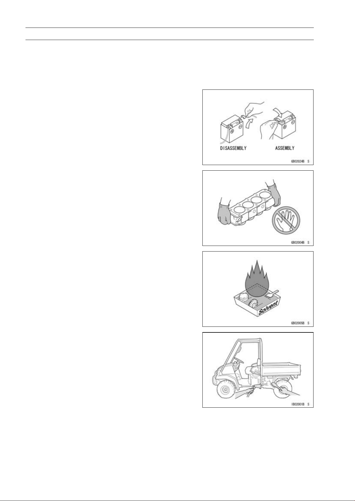
Battery Ground
Before completing any service on the vehicle, disconnect
the battery wires from the battery to prevent the engine from
accidentally turning over. Disconnect the ground wire (–)
first and then the positive (+). When completed with the
service, first connect the positive (+) wire to the positive
(+) terminal of the battery then the negative (–) wire to the
negative terminal.
Edges of Parts
Lift large or heavy parts wearing gloves to prevent injury
from possible sharp edges on the parts.
Solvent
Use a high-flush point solvent when cleaning parts. High
-flush point solvent should be used according to directions
of the solvent manufacturer.
Cleaning vehicle before disassembly
Clean the vehicle thoroughly before disassembly. Dirt or
other foreign materials entering into sealed areas during vehicle disassembly can cause excessive wear and decrease
performance of the vehicle.
Before Servicing
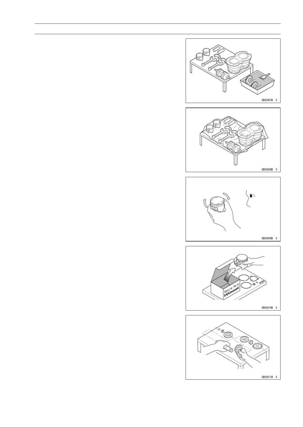
Arrangement and Cleaning of Removed Parts
Disassembled parts are easy to confuse. Arrange the
parts according to the order the parts were disassembled
and clean the parts in order prior to assembly.
Storage of Remov ed Parts
After all the parts including subassembly parts have been
cleaned, store the parts in a clean area. Put a clean cloth
or plastic sheet over the parts to protect from any foreign
materials that may collect before re-assembly.
GENERAL INFORMATION 1-3
Inspection
Reuse of worn or damaged parts may lead to serious accident. Visually inspect removed parts for corrosion, discoloration, or other damage. Refer to the appropriate sections
of this manual for service limits on individual parts. Replace
the parts if any damage has been found or if the part is beyond its service limit.
Replacement Parts
Replacement Parts must be KAWASAKI genuine or
recommended by KAWASAKI. Gaskets, O-rings, oil seals,
grease seals, circlips, cotter pins or self-locking nuts must
be replaced with new ones whenever disassembled.
Assembly Order
In most cases assembly order is the reverse of disassembly, however, if assembly order is provided in this Service
Manual, follow the procedures given.
1-4 GENERAL INFORMATION
Before Servicing
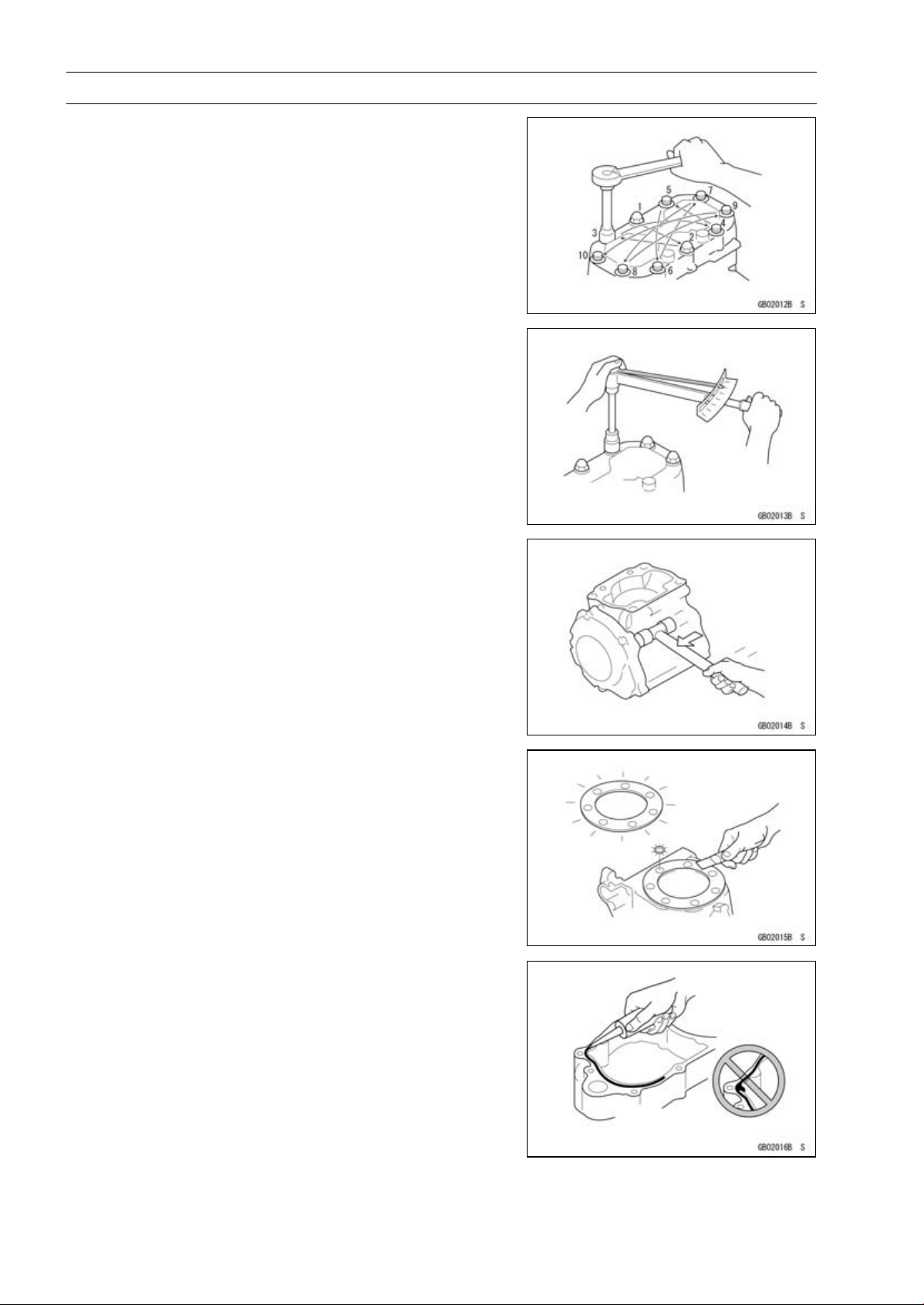
Tightening Sequence
Generally, when installing a part with several bolts, nuts,
or screws, start them all in their holes and tighten them to
a snug fit. Then tighten them according to the specified sequence to prevent case warpage or deformation which can
lead to malfunction. Conversely when loosening the bolts,
nuts, or screws, first loosen all of them by about a quarter turn and then remove them. If the specified tightening
sequence is not indicated, tighten the fasteners alternating
diagonally.
Tightening Torque
Incorrect torque applied to a bolt, nut, or screw may
lead to serious damage. Tighten fasteners to the specified
torque using a good quality torque wrench.
Often, the tightening sequence is followed twice initial
tightening and final tightening with torque wrench.
Force
Use common sense during disassembly and assembly,
excessive force can cause expensive or hard to repair damage. When necessary, remove screws that have a non
-permanent locking agent applied using an impact driver.
Use a plastic-faced mallet whenever tapping is necessary.
Gasket, O-ring
Hardening, shrinkage, or damage of both gaskets
and O-rings after disassembly can reduce sealing performance. Remove old gaskets and clean the sealing
surfaces thoroughly so that no gasket material or other
material remains. Install new gaskets and replace used
O-rings when re-assembling.
Liquid Gasket, Locking Agent
For applications that require Liquid Gasket or a
Non-Permanent Locking Agent, clean the surfaces so
that no oil residue remains before applying liquid gasket
or locking agent. Do not apply them excessively. Excessive application can clog oil passages and cause serious
damage.
Before Servicing
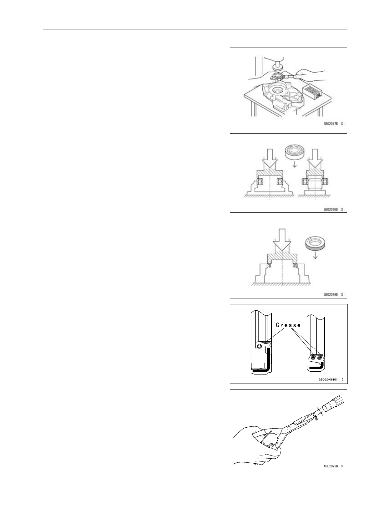
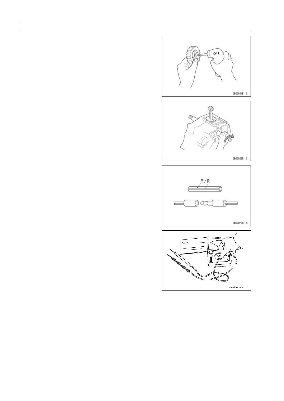
Press
For items such as bearings or oil seals that must be
pressed into place, apply small amount of oil to the contact area. Be sure to maintain proper alignment and use
smooth movements when installing.
Ball Bearing and Needle Bearing
Do not remove pressed ball or needle unless removal is
absolutely necessary. Replace with new ones whenever
removed. Press bearings with the manufacturer and size
marks facing out. Press the bearing into place by putting
pressure on the correct bearing race as shown.
Pressing the incorrect race can cause pressure between
the i nner and outer race and result in bearing damage.
GENERAL INFORMATION 1-5
Oil Seal, Grease Seal
Do not remove pressed oil or grease seals unless removal
is necessary. Replace with new ones whenever removed.
Press new oil seals with manufacture and size marks facing
out. Make sure the seal is aligned properly when installing.
Apply specified grease to the lip of seal before installing
the seal.
Circlips, Cotter Pins
Replace circlips or cotter pins that were removed with new
ones. Take care not to open the clip excessively when installing to prevent deformation.
1-6 GENERAL INFORMATION
Before Servicing
Lubrication
It is important to lubricate rotating or sliding parts during
assembly to minimize wear during initial operation. Lubrication points are called out throughout this manual, apply
the specific oil or grease as specified.
Direction of Engine Rotation
When rotating the crankshaft by hand, the free play
amount of rotating direction will affect the adjustment. Rotate the crankshaft to positive direction (clockwise viewed
from right side).
Electrical Wires
A two-color wire is identified first by the primary color and
then the stripe color. Unless instructed o therwise, electrical
wires must be connected to those of the same color.
Instrument
Use a meter that has enough accuracy for an accurate
measurement. Read the manufacture’s instructions thoroughly before using the meter. Incorrect values may lead
to improper adjustments.
Model Identification
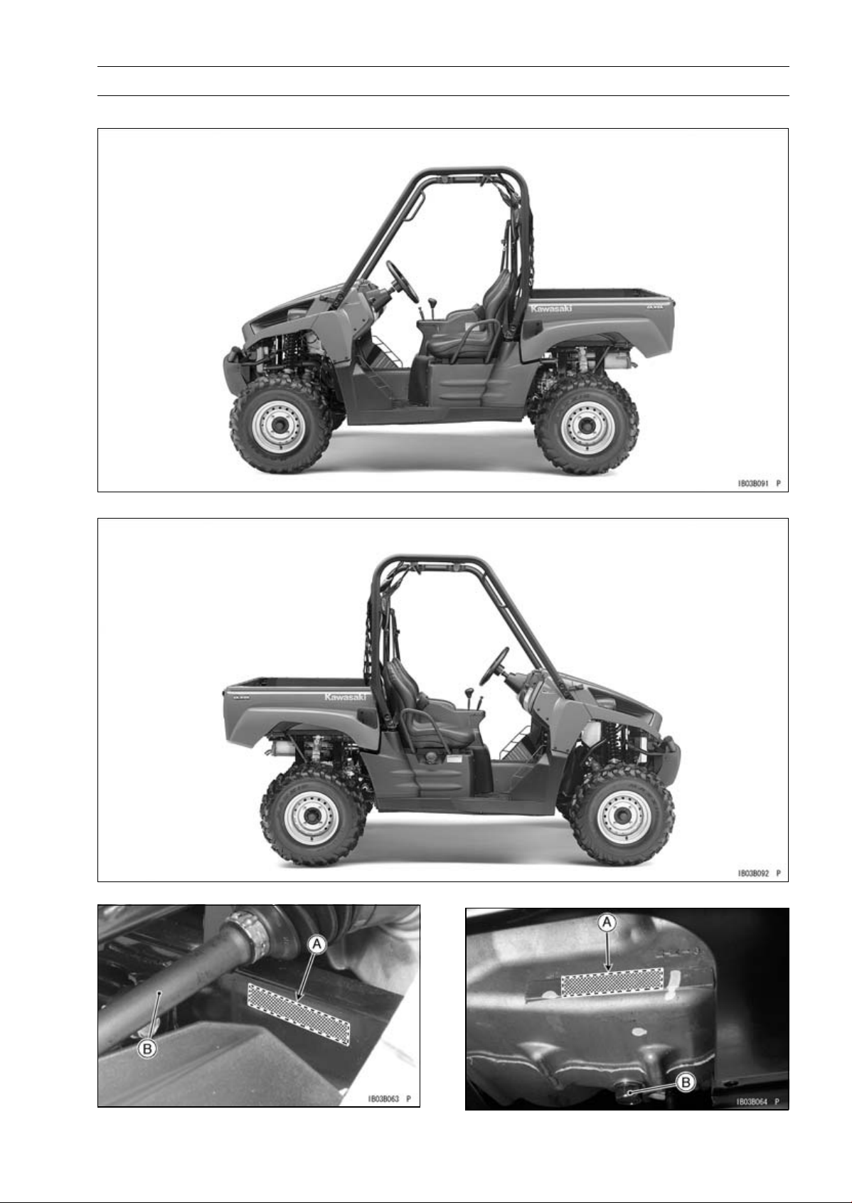
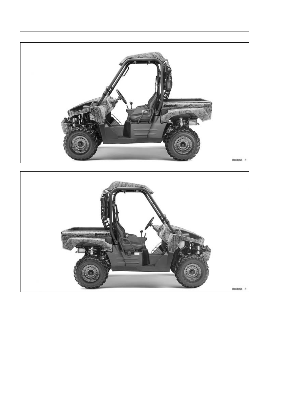
KRF750NA, TA Left Side View
GENERAL INFORMATION 1-7
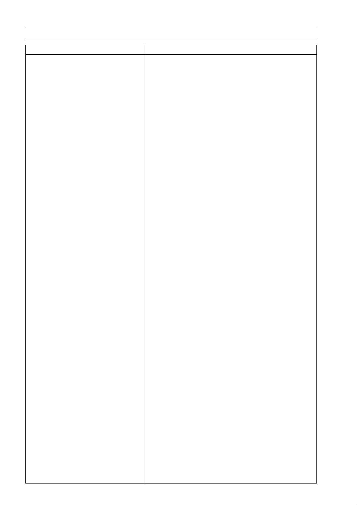
KRF750NA, TA Right Side View
Frame Number
Engine Number
[A] Frame Number
[B] Right Front Axle
[A] Engine Number
[B] Engine Oil Drain Plug
1-8 GENERAL INFORMATION
Model Identification
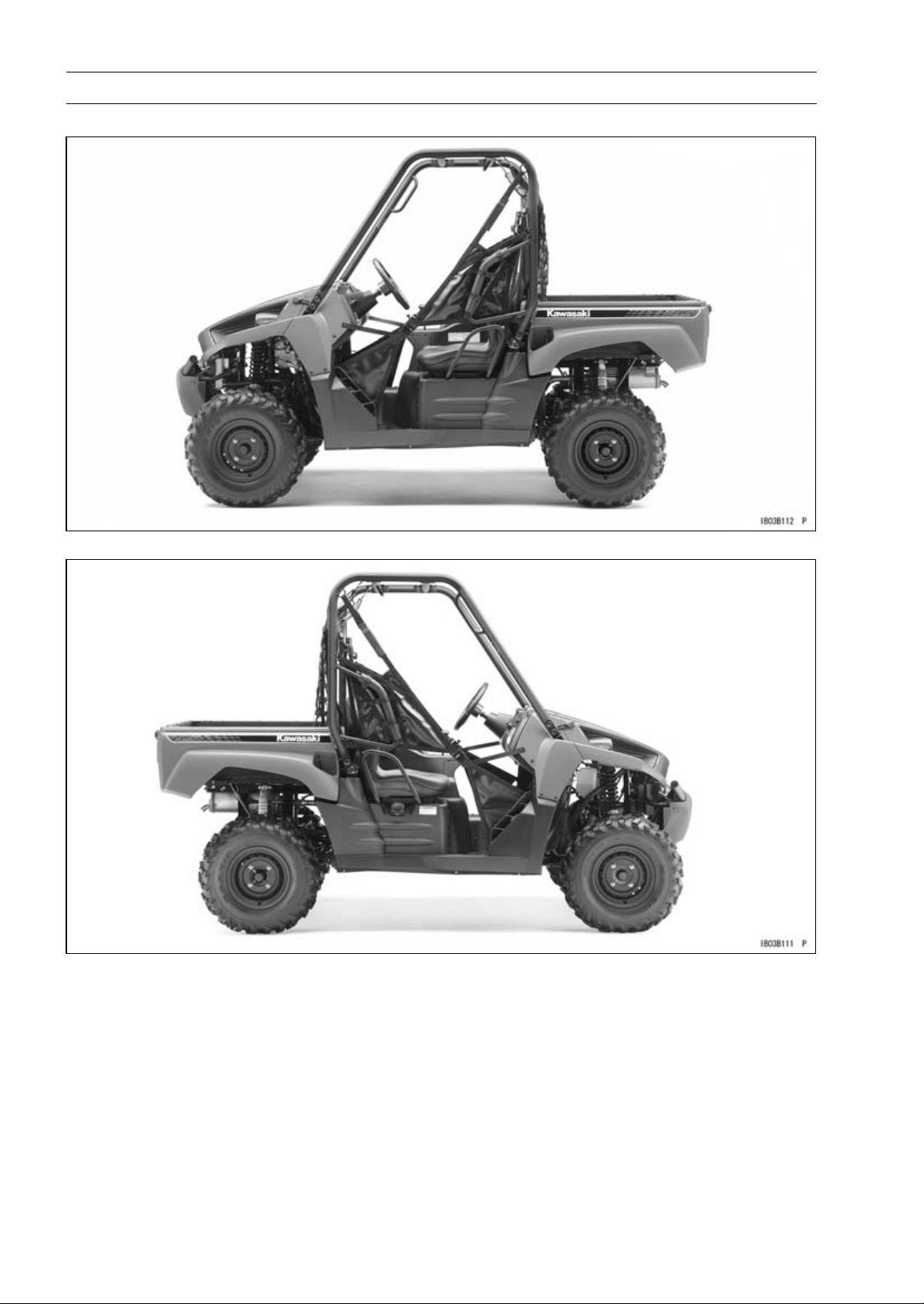
KRF750NC Left Side View
KRF750NC Right Side View
Model Identification
KRF750PA Left Side View
GENERAL INFORMATION 1-9
KRF750PA Right Side View
1-10 GENERAL INFORMATION
Model Identification
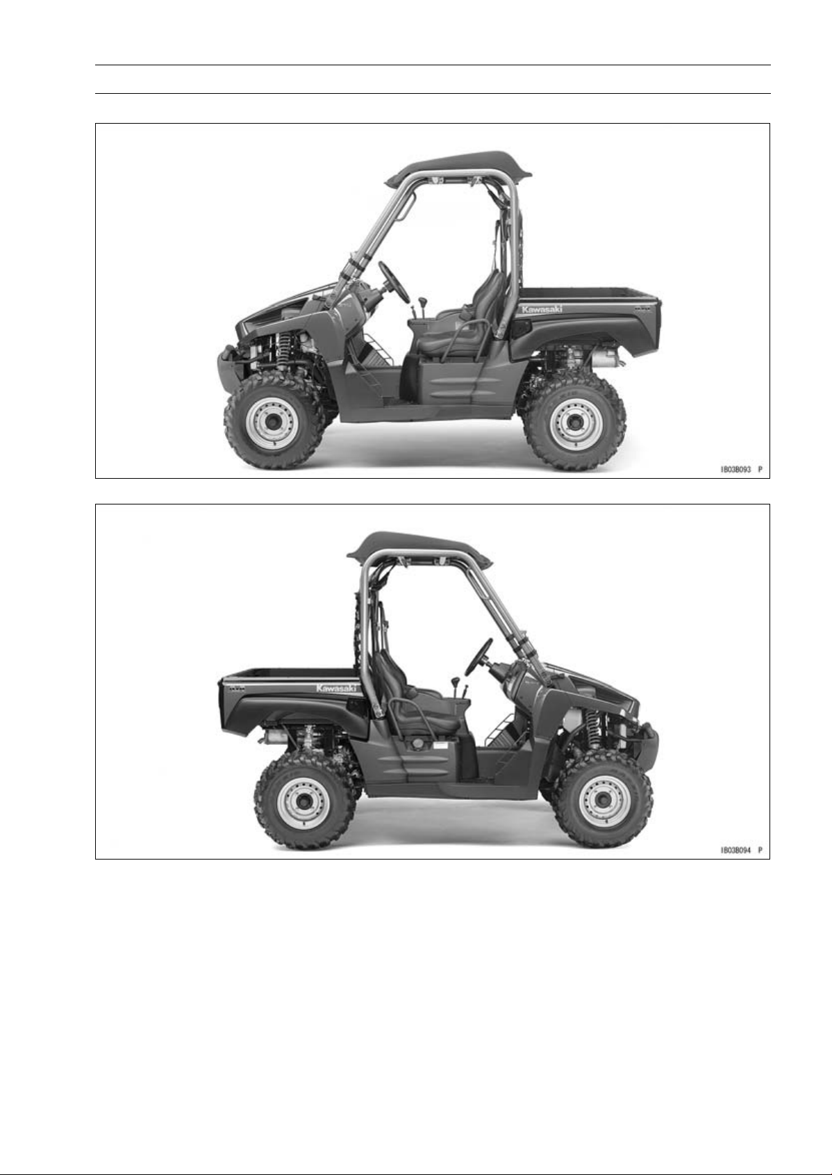
KRF750RA, VB Left Side View
KRF750RA, VB Right Side View
The KRF750RA, VB are identical to the KRF750PA in every aspect: controls, features, and
specifications except for the camouflage surface treatment.
The gun case is an optional part.

Model Identification
KRF750SA Left Side View
GENERAL INFORMATION 1-11
KRF750SA Right Side View
1-12 GENERAL INFORMATION
General Specifications
Items KRF750NA/PA/RA/SA/TA/VB ∼ ND /PD/RD/SD/VC
Dimensions
Overall Length 2 955 mm (116.3 in.)
Overall Width 1 485 mm (58.46 in.)
Overall Height :
(KRF750N/S/T) 1 925 mm (75.79 in.)
(KRF750P/R/V) 2 020 mm (79.53 in.)
Wheelbase 1 930 mm (75.98 in.)
Tread:
Front
Rear
Ground Clearance 295 mm (11.6 in.)
Seat Height 780 mm (30.7 in.)
Curb Mass:
(KRF750NA ∼ NB) 633 kg (1 396 lb), (CA) 630 kg (1 389 lb)
(KRF750NC) 636 kg (1 402 lb), (CA) 633 kg (1 396 lb)
(KRF750ND) 634 kg (1 398 lb), (CA) 631 kg (1 391 lb)
(KRF750PA/RA ∼ PB/RB/VB) 648 kg (1 429 lb), (CA) 645 kg (1 422 lb)
(KRF750PC/RC/VC) 651 kg (1 435 lb), (CA) 648 kg (1 429 lb)
(KRF750PD/RD) 649 kg (1 431 lb), (CA) 646 kg (1 424 lb)
(KRF750SA ∼ SB) 630 kg (1 389 lb), (CA) 627 kg (1 383 lb)
(KRF750SAA ∼ SBA) 631 kg (1 391 lb), (CA) 628 kg (1 385 lb)
(KRF750SC) 633 kg (1 396 lb), (CA) 630 kg (1 389 lb)
(KRF750SD) 631 kg (1 391 lb
(KRF750T) 634 kg (1 398 lb)
Front:
(KRF750NA ∼ NB) 280 kg (617 lb), (CA) 279 kg (615 lb)
(KRF750NC) 281 kg (620 lb), (CA) 280 kg (617 lb)
(KRF750ND) 278 kg (613 lb), (CA) 277 kg (611 lb)
(KRF750PA/R
(KRF750PC/RC/VC) 292 kg (644 lb), (CA) 291 kg (642 lb)
(KRF750PD/RD) 289 kg (637 lb), (CA) 288 kg (635 lb)
(KRF750SA ∼ SB) 279 kg (615 lb), (CA) 278 kg (613 lb)
(KRF750SAA ∼ SBA) 280 kg (617 lb), (CA) 279 kg (615 lb)
(KRF750SC) 280 kg (617 lb), (CA) 279 kg (615 lb)
(KRF750SD) 277 kg (611 lb), (CA) 276 kg (609 lb)
(KRF750T) 281 kg (620 lb)
Rear:
(KRF750NA ∼ NB) 353 kg (778 lb), (CA) 351 kg (774 lb)
(KRF750NC) 355 kg (783 lb), (CA) 353 kg (778 lb)
(KRF750ND) 356 kg (785 lb), (CA) 354 kg (780 lb)
(KRF750PA/RA ∼ PB/RB/VB) 357 kg (787 lb), (CA) 356 kg (785 lb)
(KRF750PC/RC/VC) 359 kg (792 lb), (CA) 357 kg (787 lb)
(KRF750PD/RD) 360 kg (794 lb), (CA) 358 kg (789 lb)
(KRF750SA ∼ SB) 351 kg (774 lb), (CA) 349 kg (770 lb)
A ∼ PB/RB/VB)
1 225 mm (48.23 in.)
1 200 mm (47.24 in.)
291 kg (642 lb
), (CA) 289 kg (637 lb)
), (CA) 628 kg (1 385 lb)
GENERAL INFORMATION 1-13
General Specifications
Items KRF750NA/PA/RA/SA/TA/VB ∼ ND/PD/RD/SD/VC
(KRF750SAA ∼ SBA) 351 kg (774 lb), (CA) 349 kg (770 lb)
(KRF750SC) 353 kg (778 lb), (CA) 351 kg (774 lb)
(KRF750SD) 354 kg (780 lb), (CA) 352 kg (776 lb)
(KRF750T) 353 kg (778 lb), (CA) 351 kg (774 lb)
Fuel Tank Capacity 28 L (7.4 US gal)
Cargo Bed (L × W × H) 830 × 1 120 × 280 mm (32.68 × 44.09 × 11.10 in.)
Seating Capacity 2
Performance
Minimum Turning Radius:
Differential Mode (2WD) 4.2 m (13.8 ft)
Locked-Axle Mode (4WD) 5.0 m (16.4 ft)
Engine
Type 4-stroke, SOHC, V2-cylinders
Cooling System
Bore and Stroke 85.0 × 66.0 mm (3.35 × 2.60 in.)
Displacement
Compression Ratio 8.8 : 1
Maximum Horsepower –
Maximum Torque 57 N·m (5.8 kgf·m, 42 ft·lb) @5 000 r/min (rpm)
Carburetion System Fuel Injection (Mikuni 34 × 2)
Starting System Electric Starter
Ignition System Battery and Coil (transistorized)
Timing Advance Electronically advanced (digital)
Ignition Timing 10° BTDC @1 110 r/mi (rpm)
Spark Plug NGK CR7E or DENSO U22ESR-N
Cylinder Numbering Method Front to rear, 1-2
Firing Order 1-2
Valve Timing:
Intake:
Open 20° BTDC
Close 44° ABDC
Duration
Exhaust:
Open 44° BBDC
Close 20° ATDC
Duration 244°
Lubrication System Forced lubrication (wet sump)
Engine Oil:
Type
Viscosity
Capacity 2.6L(2.7USqt)
Liquid-cooled
749 cm³ (45.7 cu in.)
244°
API SG, SH, SJ, SL or SM with JASO MA, MA1 or MA2
SAE 10W-40

1-14 GENERAL INFORMATION
General Specifications
Items KRF750NA/PA/RA/SA/TA/VB ∼ ND /PD/RD/SD/VC
Drive Train
Primary Reduction System:
Type Belt drive torque converter
Reduction Ratio 3.200 ∼ 0.721
Transmission Gear Rati
Forward:
High 3.549 (30/26 × 29/18 × 21/11)
Low 5.536 (36/20 × 29/18 × 21/11)
Reverse
Final Drive System:
Type
Reduction Ratio 4.375 (35/8)
Overall Drive Ratio:
Forward:
High 11.19 5
Low 17.464
Reverse 14.553
Front Final Gear Case Oil:
Type
Viscosity SAE 10W-40
Capacity 0.7L(0.74USqt)
Rear Final Gear Case Oil:
Type
Capacity 1.0L(1.06USqt)
Frame
Type Steel tube, Ladder
Caster (Rake Angle) 2.2°
Camber:
(Front) -0.7°
(Rear) -0.4°
King Pin Angle 11.4°
Trail 11 mm (0.43 in.)
Tire:
Front:
Type Tubeless
Size 26 × 8.00 - 12
Rear:
Type Tubeless
Size 26 × 10.00 - 12
Rim Size:
Front 12 × 6.0AT
Rear 12 × 8.0AT
Steering Type
o:
4.614 (16/12 × 18/16 × 29/18 × 21/11)
Shaft 4WD/2WD
API SG, SH, SJ, SL or SM with JASO MA, MA1 or MA2
MOBIL FLUID 424, CI
HYDRAULIC FLUID or EXXON HYDRAUL 560
Rack and pinion
TGO TRANSGARD TRACTOR

GENERAL INFORMATION 1-15
General Specifications
Items KRF750NA/PA/RA/SA/TA/VB ∼ ND/PD/RD/SD/VC
Suspension:
Front:
Type Double Wishbone
Wheel Travel
Rear:
Type Double Wishbone
Wheel Travel 190 mm (7.48 in.)
Brake Type:
Front Disc × 2
Rear Enclosed wet multi-plate
Parking Brake Type Enclosed wet multi-plate
Electrical Equipment
Battery (US) 12 V 14 Ah, (CA) 12 V 12 Ah
Headlight:
Type
Bulb
Brake/Tail Light 12 V 27/8 W × 2
Alternator:
Type Three - phase AC
Max Output 28 A, 14 V @6 000 rpm
Load Capacity
Maximum Vehicle Load
(Including Occupants and Cargo) 422 kg (931 lb)
Maximum Cargo Bed Load 227 kg (500 lb)
190 mm (7.48 in.)
Semi-sealed beam
12 V 35/35 W × 2
: This blank changes depending on the model.
Specifications are subject to change without notice, and may not apply to every country.
1-16 GENERAL INFORMATION
Unit Conversion Table
Prefixes for Units:
Prefix Symbol
mega M × 1 000 000
kilo k × 1 000
centi c ×0.01
milli m × 0.001
micro µ × 0.000001
Power
Units of Mass:
kg × 2.205 = lb
g × 0.03527 = oz
Units of Volume:
L × 0.2642 = gal (US)
L × 0.2200 =
L×1.057=
L × 0.8799 = qt (IMP)
L × 2.113 = pint (US)
L × 1.816 = pint (IMP)
mL × 0.03381 = oz (US)
mL × 0.02816 =
mL × 0.06102 = cu in
gal (IMP)
qt (US)
oz (IMP)
Units of Length:
km × 0.6214 = mile
m × 3.281 = ft
mm × 0.03937 = in
Units of Torque:
N·m × 0.1020 = kgf·m
N·m × 0.7376 =
N·m × 8.851 = in·lb
kgf·m × 9.807 = N·m
kgf·m × 7.233 = ft·lb
kgf·m × 86.80 = in·lb
ft·lb
Units of Pressure:
kPa × 0.01020 =
kPa × 0.1450 = psi
kPa × 0.7501 = cmHg
kgf/cm² × 98.07 = kPa
kgf/cm² × 14.22 = psi
cmHg × 1.333 = kPa
kgf/cm²
Units of Speed:
km/h
× 0.6214 = mph
Units of Force:
N × 0.1020 = kg
N × 0.2248 = lb
kg × 9.807 = N
kg × 2.205 = lb
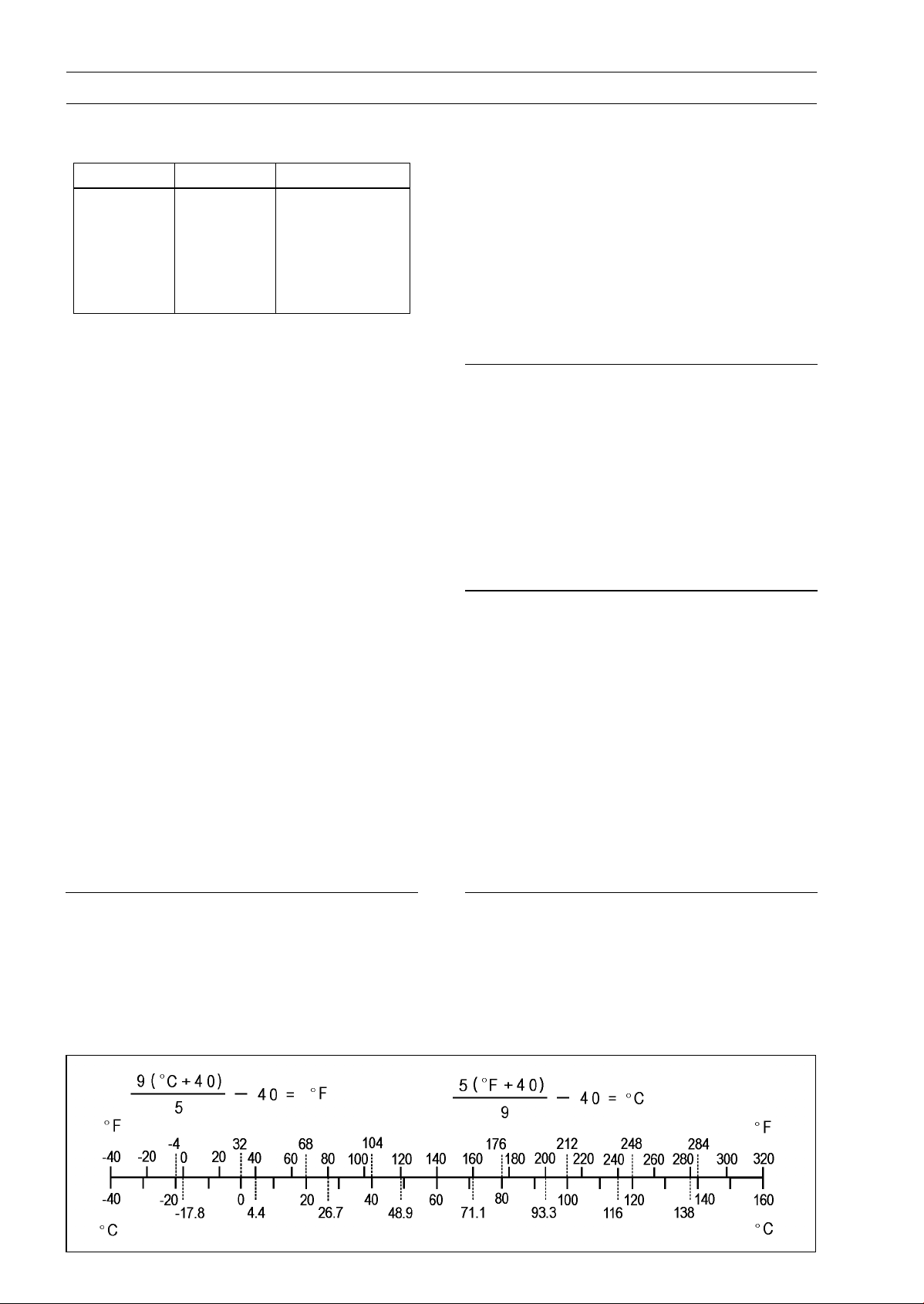
Units of Temperature:
Units of Power:
kW × 1.360 = PS
kW × 1.341 = HP
PS × 0.7355 = kW
PS × 0.9863 = HP

PERIODIC MAINTENANCE 2-1
Periodic Maintenance
Table of Contents
Periodic Maintenance Chart ................................................................................................... 2-3
Torque and Locking Agent...................................................................................................... 2-5
Specifications ......................................................................................................................... 2-13
Special Tools .......................................................................................................................... 2-15
Periodic Maintenance Procedures.......................................................................................... 2-16
Fuel System ......................................................................................................................... 2-16
Throttle Pedal Free Play Inspection.................................................................................. 2-16
Throttle Pedal Free Play Adjustment ................................................................................ 2-16
Idle Speed Inspection ....................................................................................................... 2-17
Idle Speed Adjustment...................................................................................................... 2-17
Air Cleaner Element Cleaning and Inspection .................................................................. 2-17
Air Cleaner Draining.......................................................................................................... 2-18
Fuel Hose and Connections Inspection ........................................................................... 2-18
Fuel Hose Replacement ................................................................................................... 2-19
Cooling System.................................................................................................................... 2-21
Radiator Cleaning ............................................................................................................. 2-21
Water Hoses and Connections Inspection ........................................................................ 2-21
Coolant Change ................................................................................................................ 2-21
Engine Top End ................................................................................................................... 2-24
Valve Clearance Inspection .............................................................................................. 2-24
Valve Clearance Adjustment............................................................................................. 2-26
Spark Arrester Cleaning.................................................................................................... 2-26
Converter System................................................................................................................ 2-27
Converter Drive Belt Wear Inspection............................................................................... 2-27
Drive Belt Deflection Inspection ........................................................................................ 2-29
Converter Drive Belt Deflection Adjustment...................................................................... 2-31
Actuator Lever (Engine Brake Control Lever) Assembly Inspection ................................. 2-31
Engine Lubrication System .................................................................................................. 2-32
Engine Oil Change............................................................................................................ 2-32
Oil Filter Replacement ...................................................................................................... 2-33
Wheels/Tires........................................................................................................................ 2-33
Tire Inspection ..................................................................................................................2-33
Wheels Nuts Tightness Inspection.................................................................................... 2-34
Final Drive............................................................................................................................ 2-34
Differential Shift Lever Play Inspection ............................................................................. 2-34
Differential Shift Lever Play Adjustment............................................................................ 2-34
Front Final Gear Case Oil Change ................................................................................... 2-34
Rear Final Gear Case Oil Change .................................................................................... 2-35
Brakes.................................................................................................................................. 2-36
Brake Fluid Level Inspection............................................................................................. 2-36
Brake Fluid Change .......................................................................................................... 2-37
Brake Pedal Play Inspection............................................................................................. 2-38
Brake Master Cylinder Cup and Dust Seal Replacement ................................................. 2-39
Rear Brake Master Cylinder Cup, O-ring and Boot Replace ............................................ 2-40
Brake Hose and Pipe Inspection....................................................................................... 2-42
Brake Hose Replacement ................................................................................................. 2-42
Parking Brake Pedal Inspection........................................................................................ 2-44
Front Brake Pad Wear Inspection ..................................................................................... 2-44
Front Brake Caliper Piston Seal and Dust Seal Replacement.......................................... 2-45
Rear Brake Plates Replacement....................................................................................... 2-46
2

2-2 PERIODIC MAINTENANCE
Steering ............................................................................................................................... 2-46
Steering Inspection ........................................................................................................... 2-46
Steering Joint Dust Boot Inspection .................................................................................. 2-47
Frame .................................................................................................................................. 2-47
Seat Belt Inspection .......................................................................................................... 2-47
Electrical System ................................................................................................................. 2-48
Spark Plug Cleaning/Inspection........................................................................................ 2-48
Spark Plug Gap Inspection ............................................................................................... 2-49
Brake Light Switch Inspection........................................................................................... 2-49
Brake Light Timing Adjustment ......................................................................................... 2-49
Joint Boots Inspection.......................................................................................................... 2-49
Front Axle/Steering Knuckle Joint Boots Inspection ......................................................... 2-49
Front Propeller Shaft Joint Boots Inspection..................................................................... 2-50
Tie-rod End Boots Inspection............................................................................................ 2-50
Rear Propeller Shaft Joint Boots Inspection ..................................................................... 2-50
Rear Axle/Stabilizer Joint Boots Inspection ...................................................................... 2-50
General Lubrication ............................................................................................................. 2-50
Lubrication ........................................................................................................................ 2-50
Cables.................................................................................................................................. 2-51
Inspection.......................................................................................................................... 2-51
Bolts and Nuts Tightening.................................................................................................... 2-52
Tightness Inspection ......................................................................................................... 2-52
PERIODIC MAINTENANCE 2-3
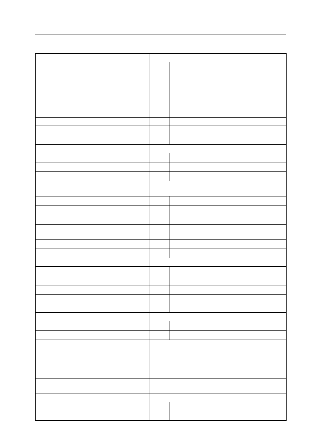
Periodic Maintenance Chart
The scheduled maintenance must be done in accordance with this chart to keep the vehicle in good
running condition. The initial maintenance is vitally important and must not be neglected.
FREQUENCY First Service Regular Service
OPERATION
ENGINE
After
20 h,
or
200
km
(120
mile)
of use
After
50 h,
or
1 000
km
(600
mile)
of use
Every
50 h,
or
1 000
km
(600
mile)
of use
Every
100 h,
or
2 000
km (1
200
mile)
of use
Every
200 h,
or
4 000
km (2
500
mile)
of use
Every
year
of use
See
Pape
Throttle pedal play-inspect
Fuel hoses and connections-inspect
Fuel hose-replace 5years 2-19
Idle speed-inspect
Spark plug-clean and gap inspect
Air cleaner-inspect *
Valve clearance-inspect
Spark arrester-clean
Engine oil-change *
Oil filter-replace *
Front and rear final gear case oil-change
Radiator-clean *
Water hoses and connections-check *
Coolant-change * 2years 2-21
Converter drive belt wear-inspect *
Converter drive belt deflection-inspect *
Differential shift lever play-inspect
Engine brake control lever-inspect *
CHASSIS
Rear brake plates-replace * every 10 000 km (6 000 mile) 2-46
• •
• •
First 2 000 km (1 200 mile); thereafter
•
• •
• •
• •
• •
• •
•
• •
every 4 000 km (2 500 mile)
•
6 months 2-32
•
•
• •
•
2-16
2-18
2-17
2-48
2-17
2-24
2-26
2-33
2-34,
35
2-21
2-21
2-27
2-29
2-34
2-31
Front brake pad wear-inspect *
Brake light switch - inspect
Brake fluid - change 2years 2-36
Brake master cylinder cup and dust seal
- replace
Rear brake master cylinder cup, O-ring,
and boot-replace *
Front brake caliper piston seal and dust
seal-replace
Brake hose - replace 4years 2-42
Brake fluid level - inspect
Brake pedal play - inspect *
• •
• •
2years 2-38
2years 2-39
2years 2-45
• •
• •
2-44
2-48
2-36
2-38
2-4 PERIODIC MAINTENANCE
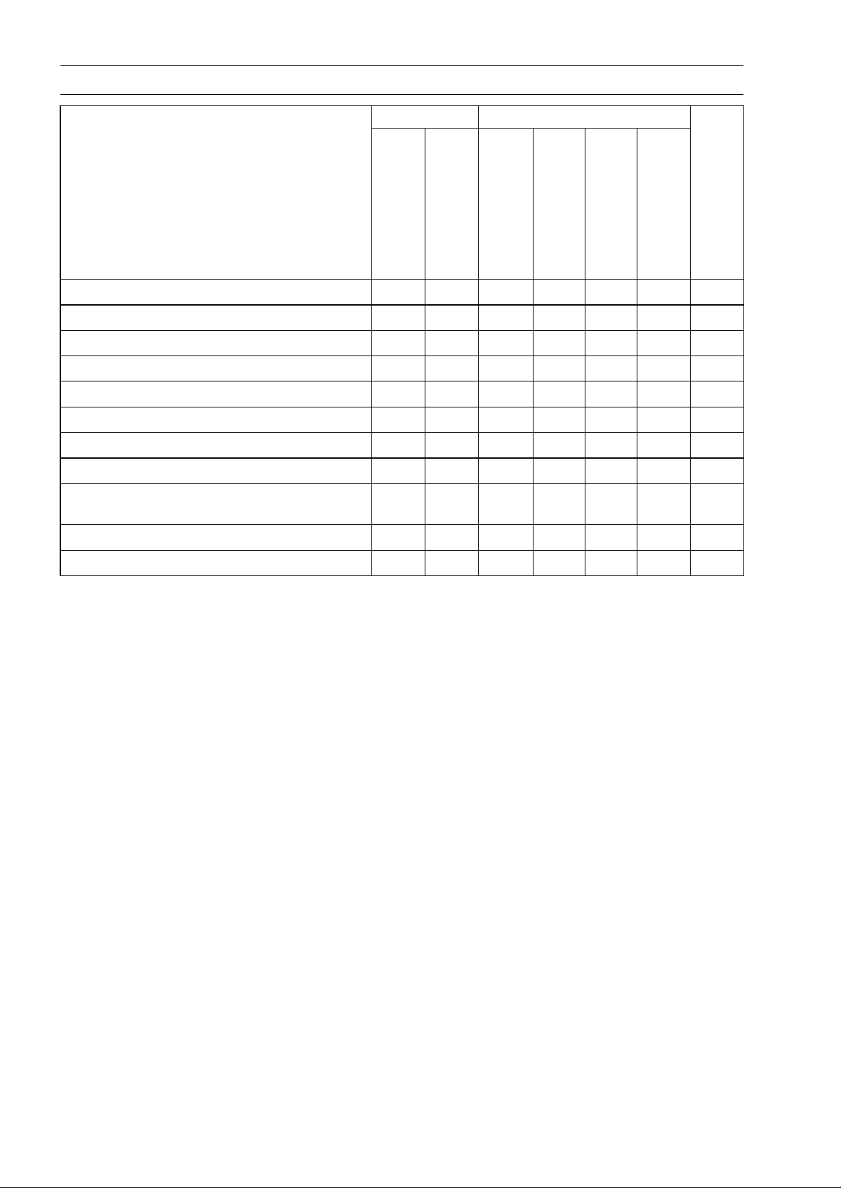
Periodic Maintenance Chart
FREQUENCY First Service Regular Service
OPERATION
After
20 h,
or
200
km
(120
mile)
of use
After
50 h,
or
1 000
km
(600
mile)
of use
Every
50 h,
or
1 000
km
(600
mile)
of use
Every
100 h,
or
2 000
km (1
200
mile)
of use
Every
200 h,
or
4000
km (2
500
mile)
of use
Every
year
of use
See
Pape
Brake hose and pipe -
Parking brake pedal - inspect
Tire wear-inspect *
Wheel nuts tightness - inspect
Joint boots - inspect
Steering-inspect
Steering joint dust boots - inspect
General lubrication - perform *
Bolts, nuts, and fasteners tightness inspect
Seat belt - inspect
Cables - inspect
*: Service more frequently when operated in mud, dust, or other harsh riding conditions, or when
carrying heavy loads or pulling a trailer.
: Clean, adjust, lubricate, torque, or replace parts as necessary.
•
inspect
• •
• •
• •
• •
• •
• •
• •
• •
2-41
2-44
2-33
2-34
2-49
2-46
2-47
•
•
•
2-50
2-52
2-47
2-51
 Loading...