

Page 1
EUROPE
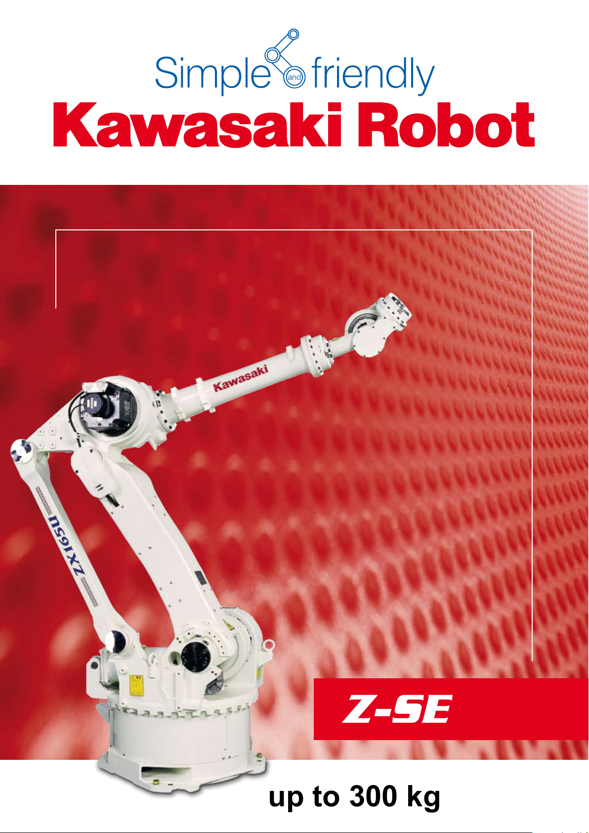
Z-SERIES
up to 300 kg payload
Page 2
»Simple and friendly«
»40 years of experience and
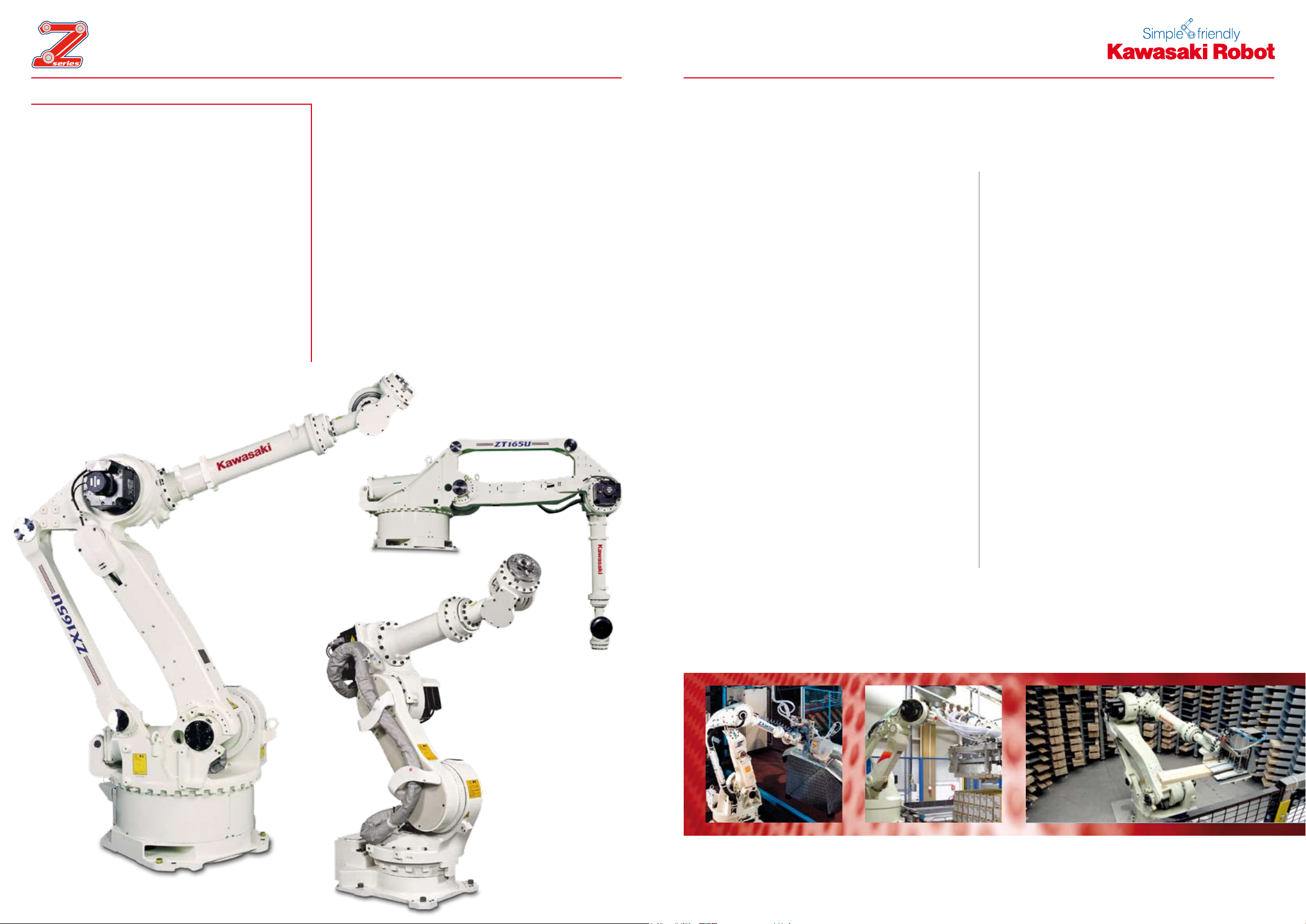
The Z-Series
INTO THE FUTURE
Handling, Welding, Mounting,
Tending are only four of the
countless domains of the
Z-Series allrounders.
state-of-the-art robot technology«
An extremely compact and light-weight design
forms the basis for high speeds and rigidity as well
as an enormous reach.
»Your goal is our task«
It was Kawasaki‘s intelligence and exibility which
made them build the most powerful robots in their
class. Combined with a high-end control system,
they reliably meet the demands of the most varied
application elds – now, in the near and far future.
Flexibility
1.
The large variation is the biggest strength of this
series. With payloads from 100 up to 300 kg as
well as a reach starting from 1634 up to massive 3530 mm can be covered. There are compact
robots, shelf mount robots and standard machines
integrated in one series which makes the Z-Series
the most versatile of the Kawasaki robot family.
2. Standardisation
The use of interchangeable modular components in
different robot models makes these machines cost
effective in the sense of maintenance and repair.
3. Reliability
The Z-Series robots of the Kawasaki family have
over the years had many model upgrades. The end
result is an high stability and robustness under load
proven in automotive and general industry.
4. Functions
Signal lines and air hoses integrated in the robot
arm allow the direct connection of grippers
without additional wiring through the robot arm.
Additionally required lines or hoses may of course
be installed at the provided fastening points in a
»simple and friendly« way.
5. Integration
An important feature of the Z-Series is the unique
space saving design. A small foot print and a slim
arm design lead to space saving application
concepts and therefore cost.
2
3
Page 3
»Standard specications«
MODEL ZX130L ZX165L ZX130U ZX165U ZX200U ZX300S ZH100 ZT130L ZT130U ZT165U ZT200U
Degrees of Freedom
Maximum Reach*
Maximum Payload 130 kg 165 kg 130 kg 165 kg 200 kg 300 kg 100 kg 130 kg 130 kg 165 kg 200 kg
Maximum Stroke
Maximum Speed
Moment
Moment of Inertia
Repeatability
(Measure Point: Middle of Flange
Axis 6)
Weight 1.400 kg 1.355 kg 1.350 kg 1.350 kg 1.350 kg 1.400 kg 750 kg 1.565 kg 1.550 kg 1.550 kg 1.550 kg
Max. linear Speed (Measure Point:
Middle of Flange Axis 6)
Controller E42 E42
Color
Installation
Ambient
Conditions
1
Axis 1 ±180 ° ±180 ° ±180 ° ±180 ° ±180 ° ±180 ° ±160 ° ±180 ° ±180 ° ±180 ° ±180 °
Axis 2 +75 ° ~ -60 ° +75 ° ~ -60 ° +75 ° ~ -60 ° +75 ° ~ -60 ° +75 ° ~ -60 ° +75 ° ~ -60 ° +120 ° ~ -60 ° +60° ~ -75° +60° ~ -75° +60 ° ~ -75 ° +60° ~ -75 °
Axis 3 +250 ° ~ -120 ° +250 ° ~ -120 ° +250 ° ~ -120 ° +250 ° ~ -120 ° +250 ° ~ -120 ° +250 ° ~ -120 ° +75 ° ~ -90 ° +165° ~ -95° +165° ~ -95° +165 ° ~ -95 ° +165° ~ -95 °
Axis 4 ±360 ° ±360 ° ±360 ° ±360 ° ±360 ° ±360 ° ±360 ° ±360 ° ±360 ° ±360 ° ±360 °
Axis 5 ±130 ° ±130 ° ±130 ° ±130 ° ±130 ° ±120 ° ±130 ° ±130 ° ±130 ° ±130 ° ±130 °
Axis 6 ±360 ° ±360 ° ±360 ° ±360 ° ±360 ° ±360 ° ±360 ° ±360 ° ±360 ° ±360 ° ±360 °
Axis 1 110 °/s 100 °/s 110 °/s 110 °/s 95 °/s 100 °/s 140 °/s 105 °/s 105 °/s 105 °/s 90 °/s
Axis 2 110 °/s 105 °/s 110 °/s 110 °/s 95 °/s 85 °/s 100 °/s 105 °/s 105 °/s 105 °/s 90 °/s
Axis 3 110 °/s 95 °/s 110 °/s 115 °/s 95 °/s 85 °/s 100 °/s 105 °/s 105 °/s 105 °/s 90 °/s
Axis 4 140 °/s 135 °/s 140 °/s 140 °/s 120 °/s 90 °/s 150 °/s 140 °/s 140 °/s 135 °/s 120 °/s
Axis 5 135 °/s 155 °/s 135 °/s 155 °/s 115 °/s 90 °/s 150 °/s 135 °/s 135 °/s 135 °/s 115 °/s
Axis 6 230 °/s 225 °/s 230 °/s 260 °/s 180 °/s 150 °/s 250 °/s 230 °/s 230 °/s 210 °/s 180 °/s
Axis 4 735 N·m 911 N·m 735 N·m 911 N·m 980 N·m 1715 N·m 874 N·m 735 N·m 735 N·m 911 N·m 980 N·m
Axis 5 735 N·m 911 N·m 735 N·m 911 N·m 980 N·m 1715 N·m 874 N·m 735 N·m 735 N·m 911 N·m 980 N·m
Axis 6 421 N·m 450 N·m 421 N·m 450 N·m 490 N·m 862 N·m 392 N·m 421 N·m 421 N·m 450 N·m 490 N·m
Axis 4 51,9 kg / m² 78,4 kg / m² 51,9 kg / m² 78,4 kg / m² 93,1 kg / m² 166,6 kg / m² 90 kg / m² 51,9 kg / m² 51,9 kg / m² 78,4 kg / m² 93,1 kg / m²
Axis 5 51,9 kg / m² 78,4 kg / m² 51,9 kg / m² 78,4 kg / m² 93,1 kg / m² 166,6 kg / m² 90 kg / m² 51,9 kg / m² 51,9 kg / m² 78,4 kg / m² 93,1 kg / m²
Axis 6 27,4 kg / m² 40,2 kg / m² 27,4 kg / m² 40,2 kg / m² 46,1 kg / m² 107,8 kg / m² 20 kg / m² 27,4 kg / m² 27,4 kg / m² 40,2 kg / m² 46,1 N / m²
Temperature
Humidity
Others
2951 mm 2810 mm 2651 mm 2651 mm 2651 mm 2501 mm 1634 mm 3530 mm 3230 mm 3230 mm 3230 mm
± 0,3 mm ± 0,3 mm
2.500 mm/s 2.500 mm/s 2.000 mm/s 2.500 mm/s
35 ~ 85 % (no Dew, nor Frost allowed) 35 ~ 85 % (no Dew, nor Frost allowed)
Installation Ambience must be free of:
• Inammable or corrosive Liquid or Gas
• Electric Noise Interferences
6 Axis 6 Axis
Munsell 10GY9/1 Munsell 10GY9/1
Floor or Ceiling Floor or Ceiling
0 ~ 45 °C 0 ~ 45 °C
Installation Ambience must be free of:
• Inammable or corrosive Liquid or Gas
• Electric Noise Interferences
Applicaton
Media
Upper Arm
Protection Class
*1 Distance between Centre of Axis 1 and Axis 5.
4 5
in
out
air
12 12 12 12 12 12 12 12 12 12 12
8 8 8 8 8 8 8 8 8 8 8
2 x Ø 12 mm 2 x Ø 12 mm 2 x Ø 12 mm 2 x Ø 12 mm 2 x Ø 12 mm 2 x Ø 12 mm 2 x Ø 12 mm 2 x Ø 12 mm 2 x Ø 12 mm 2 x Ø 12 mm 2 x Ø 12 mm
Wrist Unit: IP67 / Basic Axes: IP65 Wrist Unit: IP67 / Basic Axes: IP65
Page 4

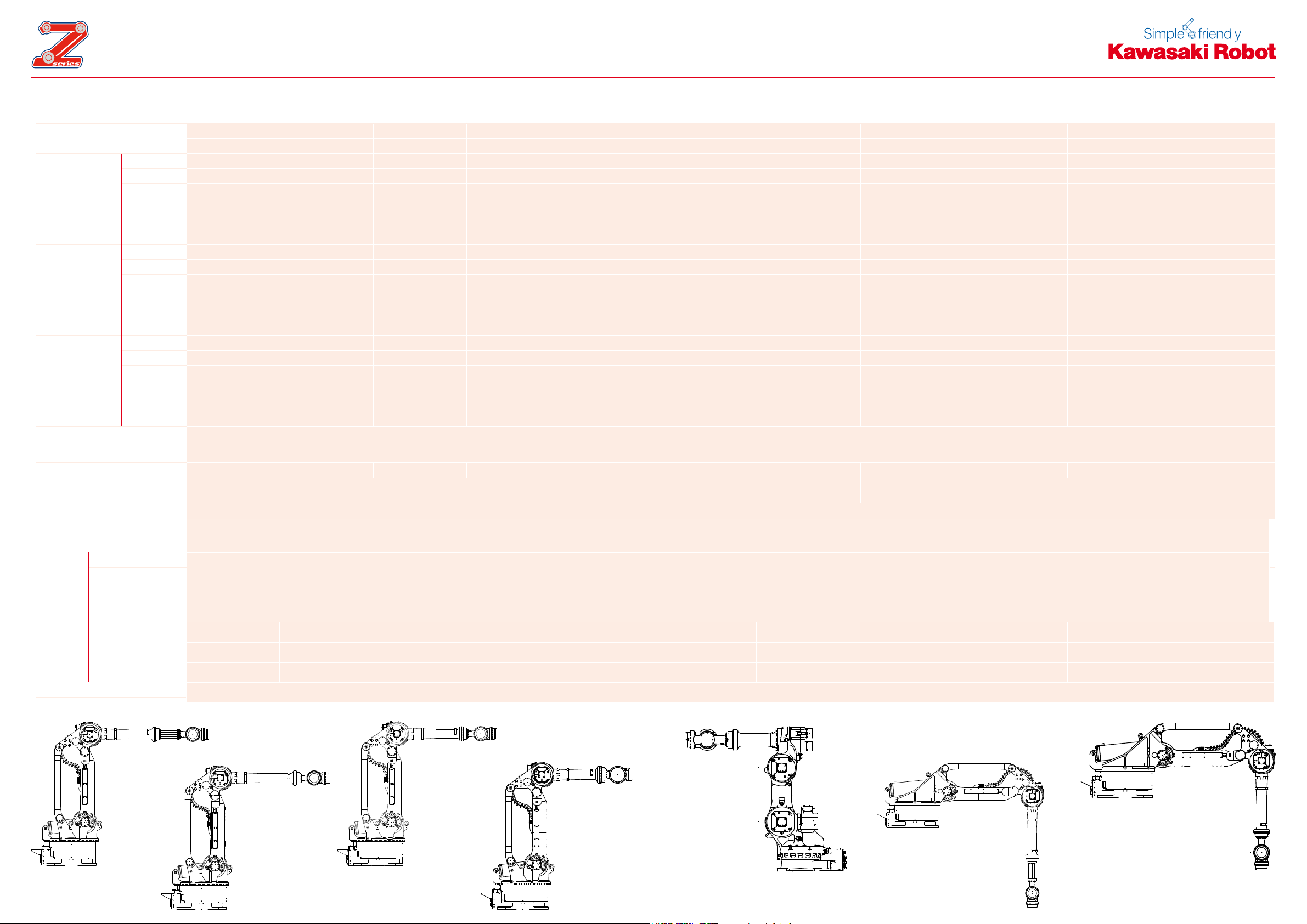
Motion Range & Dimensions Motion Range & Dimensions
288
3340
3415
1965 2651
670 1100 270
1199
601210
1300 244
Working range
based on point P
Point P
288
670 1100 270
1199
601210
3640
4015
29512265
1600
244
Working range
based on point P
Point P
288
1490
2701100670
1199
601210
3499
3733
2124 2810
1459 244
Working range
based on point P
Point P
1199
288
2501
3190
1490
1815
3115
2701100670
601210
1150 248
Point P
Working range
based on point P
ZX130L
ZX130U-165U-200U
ZX165L
6 7
ZX300S
Page 5

Motion Range & Dimensions
Point P
Working range
based on point P
530 580 300
200800
1634
572
1062
614 1964
1550
500
228
1731
4571
530 1100 300
600
2103
80
3230
244 1300
Working range
based on point P
Point P
2031
5160.6
3130
3530
220
3750
530 1100
600
300
Point P
1600
228
2103
Working range
based on point P
Motion Range & Dimensions
ZH100U
ZT130U-165U-200U
300
275
250
225
200
175
150
125
100
Maximum Payload in kg
75
50
25
ZH100U
ZX300S
ZX200U
ZX165U ZX165L
ZT200U
ZT165U
ZX130U ZX130L ZT130L
0
ZT130L
8 9
500 1000 1500 2000 2500 3000 3500
Maximum Reach in mm
Page 6

CONTROLLER
550 550
1200
1. Control
The E-Controller as consistent further development
of the existing control concept has been developed
in close cooperation with Kawasaki‘s customers.
In this way, a state-of-the-art high-end product has
been created - offering the familiar ease of operation and exceptionally high power.
2. Compact and upgradeable
A maximum of 10 external axes may be integrated,
up to three of which in the controller housing (E4x).
All established bus systems (Interbus, Probus,
ProNet…) are supported. The integrated Soft PLC
may be edited via Teach Pendant or even more
comfortably at the PC. Custom-tailored user interfaces may be programmed and used for the simpli-
ed control of the robot and also peripheral devices.
3. User-friendly system
Motor power ON and program start may be activated directly via the manual control unit. The parallel
display of two information screens (e.g. position
and signal data) facilitates the process control.
4. Functions
Integrated software functions support the most various applications. Through individual combination
and programming, highly complex systems may be
designed and realized. (e.g. Soft Absorber, Collision Detection, Conveyor Tracking and many more).
5. System
Ultra-fast execution of programs, loading and
storing processes as well as a precise continuouspath control and much more thanks to the up-todate processor design and powerful components.
8 MB RAM (80,000 steps) and USB interface as
standard.
6. Maintenance
»Simple and friendly« Due to the optimized modular
conguration of the Kawasaki control, maintenance
work is exceptionally user-friendly. Furthermore,
integrated service and diagnosis tools guarantee
increased safety in operation. Remote diagnosis via
Ethernet is also included in the standard package.
MODEL E42
Number of Controlled Axes 6 (optional 16)
Servo Motors Brushless AC Servomotors
Position Detectors Absolute Encoder
Servo System Full digital servo system
Programming Block or AS-Language
Coordinate Systems Joint, Base, Tool, external Tool
Motion Control Joint-, Linear- and Circular interpolated
External Motor power, Signal HOLD, etc.
Input 32 (optional 128)
Signals
Memory 8 MB (ca. 80.000 steps)
External Memory 2 x USB
Data Interfaces
Teach Pendant
Operation Panel Emergency Stop SW, Control Power, TEACH/REPEAT
Cable Length (Controller –
Arm, Controller – Teach Pendant)
Dimensions (WxDxH mm) 550x550x1200
Weight (kg) 180
Power Requirements AC 380-415V ± 10%, 50/60Hz, 3 Phases, 9,9kVA
Ground <100Ω, Max. Leakage Current 10mA
Safety Category 3, Performance Level d (EN ISO13849-1:2008)
Ambience Temperature / Humidity 0-45°C / 35-85% (no Dew, nor Frost allowed)
Color Munsell 10GY9/1
Note: Not all Options can be combined.
Output 32 (optional 128)
Analogue Input (optional) 8/16
Analogue Output (optional) 4/8/12/16
PC, Network, etc. 2 x RS-232C, 2 x Ethernet
Fieldbus (optional)
DeviceNet
©
, PROFIBUS©, PROFINET©, INTERBUS-S©, Ethernet/IP©, CC-Link©,
CANopen
6.4“ LCD with Touch Panel, Emergency Stop SW, Teach-Lock, Deadman SW,
10 m (Arm: optional up to 40 m), (TP: optional up to 30 m)
©
, Modbus TCP©, Control Net
Motor power, Program start, Hold/Run
©
E42
10 11
Page 7

Cautions to be taken to ensure safety
For those persons involved with the operation / service of your system, including Kawasaki Robot, they must
strictly observe all safety regulations at all times. They should carefully read the Manuals and other related
safety documents.
Products described in this catalogue are general industrial robots. Therefore, if a customer wishes to use the
robot for special purposes, which might endanger operators or if the robot has any problems please contact
us. We will be pleased to help you.
BE CAREFUL: All photos illustrated in this catalogue are frequently taken after removing safety fences and
other safety devices stipulated in the safety regulations from the Robot operation system.
Inquiries
Kawasaki Robotics GmbH Deutschland
European Headquarter
Sperberweg 29 · 41468 Neuss
E-Mail: info@kawasakirobot.de · www.kawasakirobot.de
Kawasaki Robotics (UK) Ltd.
Units 6&7 Easter Court, Europa Boulevard, Westbrook
Warrington WA5 5ZB · United Kingdom
E-Mail: info@kawasakirobot.uk.com · www.kawasakirobot.uk.com
Agent
Tel. +49-(0)2131 34 26 0
Fax +49-(0)2131 34 26 22
Tel. +44-(0)1925 71 30 00
Fax +44-(0)1925 71 30 01
Printed in Germany September 2010 Catalogue No. GE117 Materials and specification are subject to change without notice.
 Loading...