

Page 1
EUROPE
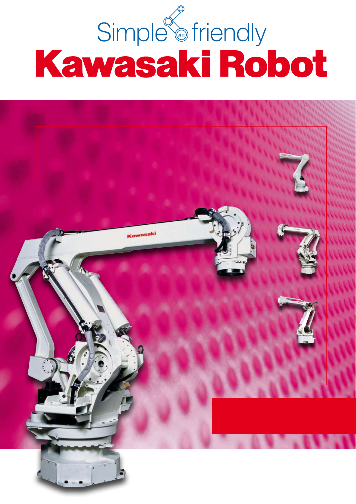
Palletizer
up to 500 kg Payload
Page 2

RD / ZD / MD
Series
»Simple and friendly«
INTO THE FUTURE
Palletizing jobs in different
weight classes are the domain
of this application orientated
robot series
»40 years of experience and
state-of-the-art robot technology«
An extremely compact and light-weight design
forms the basis for high speeds and rigidity as well
as an enormous reach.
»Your goal is our task«
It was Kawasaki‘s intelligence and exibility which
made them build the most powerful robots in their
class. Combined with a high-end control system,
they reliably meet the demands of the most varied
application elds – now, in the near and far future.
Kawasaki Palletizer
Synergy
Using the existing robot series, Kawasaki Robotics
developed the Palletizer Series. Within this series,
robots of the R-, Z-, and M- Series are used as
the basis for the equivalent palletizer. Especially
designed for palletizing, these robots are the ideal
working machines for this application.
Flexibility
The right robot for each type of palletizing
application. Cycle time, payload or max. working
envelope. Based on the application focus you
can nd the applicable Robot Model to do the
duty with maximum power.
Power
The data is telling its own tale! From 2,800 cycles
per hour (see table) of the RD080N up to 500 kg
payload of the MD500N, these robots are building
a powerful and varied selection for your highest
demands.
2
3
Page 3

RD / ZD / MD
1160
1100
250
2510
325
2065
1740
598
600
600
3521
1175
1967
588
MD500N: 856
MD400N: 624
Working range
based on point P
Point P
150 1080
680 870
1050
1400
158
277
298
307
1696.5
244
165
2100
370.8
1231.5
Working range
based on point P
Point P
2079.2
Series
MODEL RD080N ZD130S ZD250S MD400N MD500N
Degrees of Freedom 4 Axes
Maximum Reach*
1
2100 mm 3255 mm 3255 mm 3142 mm 3142 mm
Maximum Payload 80 kg 130 kg 250 kg 400 kg 500 kg
Axis 1 ±180° ±180° ±180° ±180° ±180°
Maximum Stroke
Axis 2 +140° ~ -105° +90° ~ -50° +90° ~ -50° +90° ~ -45° +90° ~ -45°
Axis 3 +40° ~ -205° +15° ~ -120° +15° ~ -120° +14° ~ -125° +14° ~ -125°
Axis 4 ±360° ±360° ±360° ±360° ±360°
Axis 1 180°/s 135°/s 95°/s 80°/s 70°/s
Maximum Speed
Axis 2 180°/s 110°/s 90°/s 70°/s 65°/s
Axis 3 175°/s 130°/s 95°/s 70°/s 45°/s
Axis 4 360°/s 400°/s 190°/s 180°/s 160°/s
Max. torque of inertia (payload) Wrist 13.7 kg/m
Repeatability
(Measure Point: Center of Flange)
± 0.07 mm ± 0.5 mm ± 0.5 mm ± 0.5 mm ± 0.5 mm
2
50 kg/m
2
100 kg/m
2
200 kg/m
2
250 kg/m
2
Weight 540 kg 1350 kg 1350 kg 2650 kg 2680 kg
Palletizing performance data
(vertical/horizontal)
RD080N*
2
: 75 mm/900 mm
RD080N*3 : 400 mm/2000 mm
ZD/MD: 400 mm/2000 mm
2800 cycles/h
(80 kg)
3
*
900 cycles/h
(80 kg)
1800 cycles/h
(60 kg)
1500 cycles/h
(130 kg)
850 cycles/h
(250 kg)
740 cycles/h
(400 kg)
600 cycles/h
(500 kg)
2
*
Controller E42 E43 E43 E44 E44
Color Munsell 10GY9/1 equivalent
Installation Floor
Temperature 0-45°
Humidity 35~85% (no Dew, nor Frost allowed)
Ambient Conditions
Others
Installation Ambience must be free of:
• Inammable or corrosive Liquid or Gas
• Electric Noise Interferences
Standard specications
MD400N/MD500N
input 12 12 12 12 12
Application Media Upper Arm
output 8 8 8 8 8
air pipes 2 x 10 mm Ø 2 x 12 mm Ø 2 x 12 mm Ø 2 x 12 mm Ø 2 x 12 mm Ø
1
Distance between center of Axis 1 and center of ange.
*
RD080N, MD400N and MD500N are using a compensating 5th axis to eliminate the parallelogram
RD080N
4 5
Page 4

RD / ZD / MD
2701250
3075.3
998
2257
255
670
810
300
1450
Working range
based on point P
Point P
Series
Standard specications
MODEL
Number of Controlled Axes
Servo Motors Brushless AC Servomotors
Position Detectors Absolute Encoder
Servo System Full digital servo system
Programming Block or AS-Language
Coordinate Systems Joint, Base, Tool, external Tool
Motion Control Joint-, Linear- and Circular interpolated
External Motor power, Signal HOLD, etc.
Input 32 (optional 128)
Signals
Memory 8 MB (ca. 80.000 steps)
External Memory 2 x USB
Data Interfaces
Output 32 (optional 128)
Analogue Input
(optional)
Analogue Output
(optional)
PC, Network, etc. 2 x RS-232C, 2 x Ethernet
Fieldbus (optional)
DeviceNet
E42 E43 E44
5 (16) 4 (16) 5 (16)
8/16
4/8/12/16
©
, PROFIBUS©, PROFINET©, INTERBUS-S©, Ethernet/IP©, CC-Link©,
CANopen©, Modbus TCP©, Control Net
©
ZD130S/ZD250S
The E-Controller – technically mature, easy to operate
and powerful
Compact, upgradeable and user-friendly
A maximum of 10 external axes may be integrated,
up to three of which in the controller housing (E4x).
All established bus systems (Interbus, Probus, ProNet…) are supported. The integrated Soft PLC may
be edited via Teach Pendant or even more comfortably at the PC (option). Custom-tailored user interfaces
may be programmed and used for the simplied
control of the robot and also peripheral devices.
Motor voltage ON and program start may be activated directly via the manual control unit. The parallel
display of two information screens (e.g. position and
signal data) facilitates the process control.
System
Ultra-fast execution of programs, loading and storing
processes as well as a precise continuous-path control and much more thanks to the up-to-date processor design and powerful components. 8 MB RAM
(80,000 steps) and USB interface as standard.
Maintenance
»Simple and friendly« – Due to the optimized modular
conguration of the Kawasaki control, maintenance
work is exceptionally user-friendly. Furthermore
integrated service and diagnosis tools guarantee
increased safety in operation. Remote diagnosis via
Ethernet is also included in the standard package.
Teach Pendant
Operation Panel Emergency Stop SW, Control Power, TEACH/REPEAT
Cable Length (Controller – Arm, Controller – Teach Pendant) 10 m (Arm: optional up to 40 m), (TP: optional up to 30 m)
Dimensions (WxDxH mm) 730x550x1200
Weight (kg) 195
Power Requirements AC 380-415V ± 10%, 50/60Hz, 3 Phases, 9,9kVA
Ground <100Ω, Max. Leakage Current 10mA
Safety Category 3, Performance Level d (EN ISO13849-1:2008)
Ambience Temperature / Humidity 0-45°C / 35-85% (no Dew, nor Frost allowed)
Color Munsell 10GY9/1 equivalent
6.4“ TFT LCD with Touch Panel, Emergency Stop SW, Teach-Lock, Deadman SW,
Motor power, Program start, Hold/Run
Note: Not all Options can be combined.
6 7
Page 5

Cautions to be taken to ensure safety
For those persons involved with the operation / service of your system, including Kawasaki Robot, they must
strictly observe all safety regulations at all times. They should carefully read the Manuals and other related
safety documents.
Products described in this catalogue are general industrial robots. Therefore, if a customer wishes to use the
robot for special purposes, which might endanger operators or if the robot has any problems please contact
us. We will be pleased to help you.
BE CAREFUL: As Photographs illustrated in this catalogue are frequently taken after removing safety fences
and other safety devices stipulated in the safety regulations from the Robot operation system.
Inquiries
Kawasaki Robotics GmbH Deutschland
European Headquarter
Sperberweg 29 ∙ 41468 Neuss
E-Mail: info@kawasakirobot.de ∙ www.kawasakirobot.de
Kawasaki Robotics (UK) Ltd.
Units 6&7 Easter Court, Europa Boulevard, Westbrook
Warrington WA5 5ZB ∙ United Kingdom
E-Mail: info@kawasakirobot.uk.com ∙ www.kawasakirobot.uk.com
Agent
Tel. +49-(0)2131 34 26 0
Fax +49-(0)2131 34 26 22
Tel. +44-(0)1925 71 30 00
Fax +44-(0)1925 71 30 01
Printed in Germany September 2010 Catalogue No. GE117 Materials and specification are subject to change without notice.
 Loading...