

Page 1

EUROPE
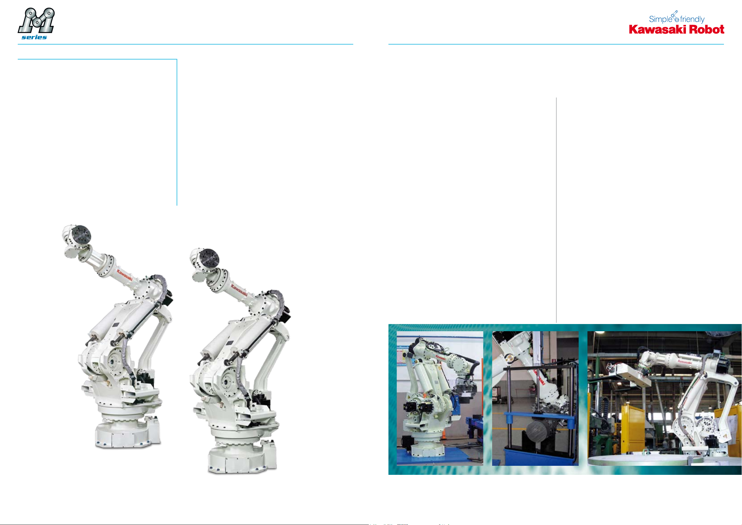
M-SERIES
up to 700 kg payload
Page 2
»Simple and friendly«
»40 years of experience and
The M-Series
INTO THE FUTURE
Handling, Welding, Mounting
and Tending are only four of
the countless domains of the
M-Series allrounders.
state-of-the-art robot technology«
An extremely compact and light-weight design
forms the basis for high speeds and rigidity as well
as an enormous reach.
»Your goal is our task«
It was Kawasaki‘s intelligence and exibility which
made them build the most powerful robots in their
class. Combined with a high-end control system,
they reliably meet the demands of the most varied
application elds – now, in the near and far future.
Power
1.
With an enormous amount of torque available at
each axis these machines are the most powerful
robots of the Kawasaki Robot Family. With a payload from 350 to 700 kg and a reach from 2540
up to 3018 mm.
2. Standardisation
The use of interchangeable modular components
in different robot models makes these machines cost
effective in the sense of maintenance and repair.
3. Reliability
The M-Series robots of the Kawasaki family have
over the years had many model upgrades. The end
result is a high stability and robustness under
maximum load proven in both automotive and
general industries.
4. Functions
Allow for the direct connection of grippers without
additional wiring through the robot arm. Additionally
required lines or hoses can be installed at the provided fastening points. The robots of the M-Series
are equipped with signal lines and air hoses integrated in the robot arm.
5. Integration
The basic principal for the design of the Kawasaki
robot family has also been used for the M-Series
development. A small footprint and minimized
interference contour, enables space saving application cells and decrease costs.
32
Page 3
»Standard specications«
1160 1100 250
2510
310325 1600
459
3502
965 2053
Wo rking range based on point P
Point P
481 624
1160 1100 250
2510
310325 1350
3169.6
213
730 2048
Point P
Wo rking range based on point P
481 624
Arbeitsbereich basierend auf Punkt P
MODEL MX350L MX420L MX500N MX700N
Degrees of Freedom
Maximum Reach*
1
3018 mm 2778 mm 2540 mm 2540 mm
6 Axis
Maximum Payload 350 kg 420 kg 500 kg 700 kg
Axis 1 ±180 ° ±180 ° ±180 ° ±180 °
Axis 2 +90 ° ~ -45 ° +90 ° ~ -45 ° +90 ° ~ -45 ° +90 ° ~ -45 °
Maximum Stroke
Axis 3 +20 ° ~ -115 ° +20 ° ~ -125 ° +20 ° ~ -130 ° +20 ° ~ -130 °
Axis 4 ±360 ° ±360 ° ±360 ° ±360 °
Axis 5 ±110 ° ±110 ° ±110 ° ±110 °
Axis 6 ±360 ° ±360 ° ±360 ° ±360 °
Axis 1 80 °/s 80 °/s 80 °/s 65 °/s
Axis 2 70 °/s 70 °/s 70 °/s 50 °/s
Maximum Speed
Axis 3 70 °/s 70 °/s 70 °/s 45 °/s
Axis 4 80 °/s 80 °/s 80 °/s 50 °/s
Axis 5 80 °/s 80 °/s 80 °/s 50 °/s
Axis 6 120 °/s 120 °/s 120 °/s 95 °/s
Axis 4 2740 N·m 3290 N·m 3920 N·m 5488 N·m
Moment
Axis 5 2740 N·m 3290 N·m 3920 N·m 5488 N·m
Axis 6 1960 N·m 1960 N·m 1960 N·m 2744 N·m
Axis 4 400 kg ·m² 400 kg ·m² 400 kg ·m² 600 kg ·m²
Moment of Inertia
Axis 5 400 kg ·m² 400 kg ·m² 400 kg ·m² 600 kg ·m²
Axis 6 259 kg ·m² 259 kg ·m² 259 kg ·m² 388 kg ·m²
Motion Range & Dimensions
MX350L
Repeatability
(Measure Point: Middle of Flange)
± 0,5 mm
Weight 2.800 kg 2.800 kg 2.750 kg 2.860 kg
Max. linear Speed
(Measure Point: Middle of Flange)
2000 mm/s
Controller E44
Color
Installation
Ambient
Conditions
Temperature
Humidity
Others
35 ~ 85 % (no Dew, nor Frost allowed)
Installation Ambience must be free of:
• Inammable or corrosive Liquid or Gas
Munsell 10GY9/1
Floor
0 ~ 45 °C
• Electric Noise Interferences
Application
Input Signals
Media
Output Signals
Upper Arm
Air
IP Code
*1 Distance between Centre of Axis 1 and Axis 5.
Wrist Unit: IP67 / Basic Axes: IP65
12
8
2 x Ø 12 mm
MX420L
4 5
Page 4

1160 1100 250
2510
310
32 2839
495 2045
325 1100
Point P
Wo rking range based on point P
481
MX700N: 856
MX500N: 624
Motion Range & Dimensions
MX500N/MX700N
The E-Controller – technically mature, easy to operate
and powerful
MODEL E44
Number of Controlled Axes 6 (optional 16)
Servo Motors Brushless AC Servomotors
Position Detectors Absolute Encoder
Servo System Full Digital Servo System
Programming Block or AS-Language
Coordinate Systems Joint, Base, Tool, external Tool
Motion Control Joint-, Linear- and Circular interpolated
External Motor Power, Signal Hold, etc.
Input 32 (optional 128)
Signals
Memory 8 MB (ca. 80.000 steps)
External Memory 2 x USB
Data Interfaces
Teach Pendant
Operation Panel Emergency Stop SW, Control Power, Teach/Repeat
Cable Length (Controller – Arm),
(Controller – Teach Pendant)
Dimensions (WxDxH mm) 550x550x1200
Weight (kg) 180
Power Requirements
Ground <100Ω, Max. Leakage Current 10mA
Safety Category 3, Performance Level d (EN ISO13849-1:2008)
Ambience Temperature / Humidity 0-45°C / 35-85% (no Dew, nor Frost allowed)
Color Munsell 10GY9/1
Note: Not all Options can be combined.
Output 32 (optional 128)
Analogue Input (optional) 8/16
Analogue Output (optional) 4/8/12/16
PC, Network, etc. 2 x RS-232C, 2 x Ethernet
Fieldbus (optional)
DeviceNet
©
, PROFIBUS©, PROFINET©, INTERBUS-S©, Ethernet/IP©, CC-Link©, CANopen©,
6.4“ LCD with Touch Panel, Emergency Stop SW, Teach-Lock, Deadman SW,
10 m (Arm: optional up to 40 m), (TP: optional up to 30 m)
Modbus TCP©, Control Net
Motor Power, Program Start, Hold/Run
AC 380-415V ± 10 %,
50/60Hz, 3 Phases,
max. 9,9kVA (E44)
©
Compact, upgradeable and user-friendly
A maximum of 10 external axes may be integrated,
up to three of which in the controller housing (E4x).
All established bus systems (Interbus, Probus, ProNet…) are supported. The integrated Soft PLC may
be edited via Teach Pendant or even more comfortab-
System
Ultra-fast execution of programs, loading and storing
processes as well as a precise continuous-path control and much more thanks to the up-to-date processor design and powerful components. 8 MB RAM
(80,000 steps) and USB interface as standard.
ly at the PC (option). Custom-tailored user interfaces
may be programmed and used for the simplied
control of the robot and also peripheral devices.
Motor voltage ON and program start may be activated directly via the manual control unit. The parallel
display of two information screens (e.g. position and
signal data) facilitates the process control.
6 7
Maintenance
»Simple and friendly« – Due to the optimized modular
conguration of the Kawasaki control, maintenance
work is exceptionally user-friendly. Furthermore
integrated service and diagnosis tools guarantee
increased safety in operation. Remote diagnosis via
Ethernet is also included in the standard package.
Page 5

Cautions to be taken to ensure safety
For those persons involved with the operation / service of your system, including Kawasaki Robot, they must
strictly observe all safety regulations at all times. They should carefully read the Manuals and other related
safety documents.
Products described in this catalogue are general industrial robots. Therefore, if a customer wishes to use the
robot for special purposes, which might endanger operators or if the robot has any problems please contact
us. We will be pleased to help you.
BE CAREFUL: All photos illustrated in this catalogue are frequently taken after removing safety fences and
other safety devices stipulated in the safety regulations from the Robot operation system.
Inquiries
Kawasaki Robotics GmbH Deutschland
European Headquarter
Sperberweg 29 · 41468 Neuss
E-Mail: info@kawasakirobot.de · www.kawasakirobot.de
Kawasaki Robotics (UK) Ltd.
Units 6&7 Easter Court, Europa Boulevard, Westbrook
Warrington WA5 5ZB · United Kingdom
E-Mail: info@kawasakirobot.uk.com · www.kawasakirobot.uk.com
Agent
Tel. +49-(0)2131 34 26 0
Fax +49-(0)2131 34 26 22
Tel. +44-(0)1925 71 30 00
Fax +44-(0)1925 71 30 01
Printed in Germany February 2011 Catalogue No. GE119 Materials and specification are subject to change without notice.
 Loading...