

Page 1
Page 2
Engineered for Excellence
Kawasaki Robotics has become known worldwide for manufacturing the highest performance robots on the planet. Over the
past 30 years, well over 65,000 Kawasaki Robots have been
installed. During this period, Kawasaki has obtained an
unparalleled level of experience in all types of industries
and applications. Our engineers continuously listen
to the demands of our customers, and as a result,
have designed a completely new line of
explosion-proof painting robots.
The K-Series painting robots
were developed with our
“Simple and Friendly”
concept. With eight
explosion-proof models
available, Kawasaki has
a robot that will suit any
robotic painting
application from small
paint cells to complete
multi-robot automotive
finishing systems.
Pre-Engineered Systems
The K-Series Robots can be provided as part of a Kawasaki
Robotics pre-engineered finishing system. These designs
are ideal for stand alone finishing cells and are available in a
variety of sizes and configurations. Kawasaki currently offers
five unique explosion proof cells providing a compact yet
sophisticated solution to your finishing needs. These designs
are standard, therefore proven in the field. Choosing a
K-Series finishing system means less time spent in design
and manufacturing resulting in the shortest time to production.
For full details and specifications, please visit our website at:
www.kawasakirobotics.com.
www.kawasakirobotics.com
Page 3
1
1
2
3
1
2
3
4
1
2
3
4
5
1
2
Kawasaki’s experience and expertise in the field of robotic painting has
resulted in the production of the highest-performance units in the industry.
A comprehensive line-up of robots
Kawasaki offers eight unique explosion-proof
models from the KF 121 for small applications
to the KE 610 robots for automotive inner and
outer body finishing. Kawasaki can offer the
right solution for your robotic paint application
by matching a K-Series robot with your system
requirements.
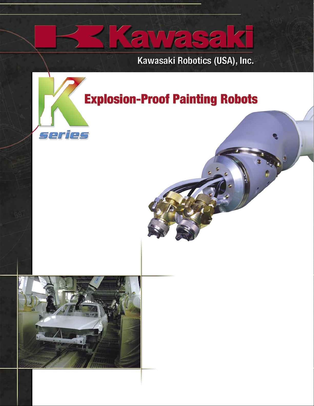
Built-in hoses
Hollow wrist versions of the K-Series arms are
fitted with built-in hoses as standard equipment.
Internally fitting the hoses minimizes overspray
adhering to the piping, reducing the risk of
contaminants in the finish.
Easy system integration
A control panel is provided to enhance the ease
of system building and interfacing with other
peripheral equipment. Kawasaki Robotics can
provide pre-engineered painting systems for
quick start-up and integration with a rail, shuttle,
spinner, etc.
Kawasaki’s painting experience
Over 30 years of robotic painting experience has
enabled Kawasaki to design robots to meet the
needs of today’s most demanding customers.
The K-Series robots are now equipped with more
advanced functions than ever offered before,
resulting in increased productivity.
Customer Support
Our professional staff will be available for
support from the initial planning stage right up to
equipment start-up. This service will be of great
benefit to those new to painting applications.
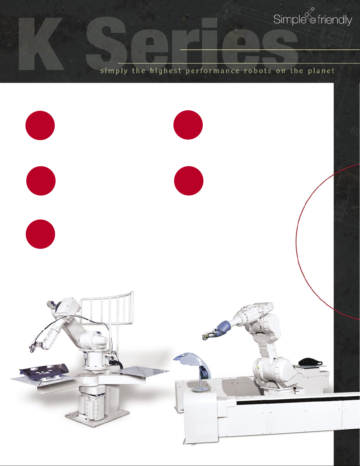
Kawasaki Robotics offers pre-engineered paint system peripherals.
Servo Twister and KF121 Robot
Servo Tombow, Servo Spinner, and Servo Turntable also
available. Visit www.kawasakirobotics.com for more information.
Servo Shuttle and KF193 Robot
Page 4

TYPE KF121 KF192 KF193 KF262 KF263 KF264 KE610H KE610L
Degrees of Freedom
Wrist Type RBR BBR
3Rø40
(Hose Built-In)
BBR
3Rø40
(Hose Built-In)
3Rø70
(Hose Built-In)
JT1(Turning)
JT2(lower arm)
JT3(Upper arm)
JT4
JT5
JT6
Max. Speed
Max. Payload
6
±160°
±360° ±720°
±90°
±150°
±360° ±720°
±410°±360°
±0.2 mm
Pressurized and Intrinsically Safe (Class 1, Zone 1, Group IIB & T4 certified)*
0~ 40°C
Repeatability
Weight
Explosion Protection
Ambient Temperature
Body color
JT4
JT5
JT6
JT4
JT5
JT6
Moment
±360°
±360°
±360°
±720°
±720°
±410°
±270°
±145°
±360°
±150°
+110° ~ – 60°
+90
° ~ – 80°
1.5 m/s 2.0 m/s
±0.5 mm
±1.0 mm
Wrist: 15 kg
Arm: 25 kg
Wrist: 15 kg
Arm: 20 kg
Kawasaki Standar
d
7.8 N·m
7.8 N·m
2.9 N·m
33.3 N·m
28.8 N·m
7.9 N·m
33.3 N·m
28.8 N·m
7.9 N·m
33.2 N·m
26.7 N·m
7.9 N·m
33.2 N·m
26.7 N·m
7.9 N·m
35.4 N·m
27.7 N·m
7.9 N·m
61.1 N·m
48.4 N·m
18.3 N·m
0.17 kg·m
2
0.17 kg·m
2
0.06 kg·m
2
1.28 kg·m
2
0.96 kg·m
2
0.11 kg·m
2
1.28 kg·m
2
0.96 kg·m
2
0.11 kg·m
2
1.27 kg·m
2
0.82 kg·m
2
0.11 kg·m
2
1.27 kg·m
2
0.82 kg·m
2
0.11 kg·m
2
1.45 kg·m
2
0.89 kg·m
2
0.11 kg·m
2
2.59 kg·m
2
1.63 kg·m
2
0.23 kg·m
2
Moment
of Inertia
Max. Reach
Range of Motion
Work Envelope
1,240 mm 1,973 mm 1,973 mm 2,665 mm 2,665 mm 2,668 mm 2,714 mm 3,014 mm
5 kg Wrist: 12 kg Arm: 20 kg
140 kg 690 kg 720 kg 720 kg 740 kg 770 kg 800 kg 810 kg
±148°
+108
° ~ –58°
+88
° ~ –78°
Maximum reach: The RBR (Roll Bend Roll) wrist refers to the distance from the centre of JT1 to the centre of JT5.
The BBR (Bend Bend Roll) wrist is the distance from the top arm centre line to the JT4 axis.
The 3R (Roll Roll Roll) wrist is the distance from JT1 to the axis cross-point between JT4 and JT5.
Other options or Software : Please contact us.
1 N·m = 0.102 kgf·m
1 kg·m
2
= 0.102 kgf·m·s
2
1 kgf = 2.2 lbf
1 m = 3.28 ft.
* contact KRI for latest certifications.
Wrist Configurations
KF121
•RBR
JT6
(Roll)
JT5
(Bend)
JT4
(Roll)
KF192 and KF262
•BBR
JT6
(Roll)
JT4
(Bend)
JT5
(Bend)
KF193 and KF263 (40mm I.D. hollow wrist)
•3R
JT5
JT4
(Roll)
KF264, KE610H and KE610L (70mm I.D. hollow wrist)
•3R
JT5
(Roll)
(Roll)
JT6
(Roll)
JT6
(Roll)
JT4
(Roll)
Page 5

JT6:720°
JT5:290
°
JT4:540°
JT3:480°
JT1:320°
JT2:180°
150
°
150
°
90
°
90
°
R550
R302
R550
R1,150
2-M6-10/16
M6-10/16
4-M 6-10 /16
1,630
550600400
18
154 100
80
117
109
64
142
249.5 329.5
50
15473
Z
base
1,240
off-set : 90
(2-M10 Eye Bolts)
Purging air inlet port
(Tube diameter ø12)
100
280 150
140
13
0
JT5
JT3
JT2
JT1
JT6
JT4
258 240
14
3
19
7
14
3
309
598
Detail C
1,973
598
454 2,433
850 250
200
850710
+360°
-360°
+90°
+110
°
-15
0°
+15
0°
-80°
-60°
2X2-M6-13/18
+360°
+360°
-360°
-360°
45
100
280 150
140
13
0
JT5
JT6
JT4
+360°
-360°
2X2-M6-13/18
+360°
+360°
-360°
-360°
45
137.5
95
(73.61)
JT5
JT4
JT3
JT2
JT1
JT6
258 240
225 211
197
309
598
Detail C
1,973
598
454 2,433
850 250
200
850710
410°
+
410°
–
720°
–
60
°
85
720°
+
720°
+
720°
–
90°
+
110°
+
150°
+
150°
–
80°
–
60°
–
137.5
95
(73.61)
JT5
JT4
JT6
410°
+
410°
–
720°
–
60
°
85
720°
+
720°
+
720°
–
JT3
JT2
JT1
258 240
143 1
43
19
7
309
598
2,665
697
1,300 250
200
1,100710
982 3,125
+90°
110
°
+
150°
+
150°
–
–80°
60°
–
100
45
50
280 150
140
13
0
JT5
JT6
JT4
Detail C
360°
+
360°
+
360°
+
360°
–
360°
–
360°
–
3X
2-M6-13/18
300
100
45
50
280 150
140
13
0
JT5
JT6
JT4
360°
+
360°
+
360°
+
360°
–
360°
–
360°
–
3X
2-M6-13/18
300
Eight unique robot models to suit any painting application.
KF121
KF121
KF192 KF262KF193
KF262
KF192
KF193
Page 6

KF263 KF264 KE610LKE610H
137.5
95
(73.61)
JT5
JT4
JT3
JT2
JT1
JT6
258 240
225 211
19
7
309
598
Detail C
2,665
697
1,300 250
200
1,100
710
982 3,125
+ 410°
- 410°
-720°
60
°
+720°
+720°
-720°
+90°
+110
°
+15
0°
-15
0°
-80°
-60°
85
137.5
95
(73.61)
JT5
JT4
JT6
+ 410°
- 410°
-720°
60
°
+720°
+720°
-720°
85
158.5
108.5
100
(86.6)
JT5
JT4
JT3
JT2
JT1
JT6
258 240
248 228
19
7
309
598
Detail C
2,668
715
1,300 250
220
1,100710
985 3,128
+410°
-410°
-720°
60
°
+720°
+720°
-720°
+90°
+110
°
+15
0°
-15
0°
-80°
-60°
158.5
108.5
100
(86.6)
JT5
JT4
JT6
+410°
-410°
-720°
60
°
+720°
+720°
-720°
737
60
1,850
750
146
178
off-set:200
R537
2,714
R1,414
R1,414
R2,514.21
1,004 3,264
1,932
125
200
150
650
4-M8 Depth18
337
1,100
108
°
58
°
220
505477
Base
166
°
off-set:200
Payload of upper arm
(Center of gravity)
Payload of wrist
(Center of gravity)
FLEXIBLE CONDUIT
(option)
JT3
Up 88°
Down 78°
JT2
Forward 108°
Backward 58°
1400
692
60
2,150
750
3,014
3,5641,096
R492
R
1,414
R1,41
4
R2,814.22
2,186
58
°
125
200
150
650
Base
178
337
108
°
off-set:200
220
146
505477
1,400
off-set:200
Payload of upper arm
(Center of gravity)
4-M8 Depth18
JT3
Up 88°
Down 78°
JT2
Forward 108°
Backward 58°
FLEXIBLE CONDUIT
(option)
166
°
Payload of wrist
(Center of gravity)
1400
158.5
108.5
100
(86.6)
JT5
JT4
JT6
+410°
-410°
-720°
60
°
+720°
+720°
-720°
158.5
108.5
100
(86.6)
JT5
JT4
JT6
+410°
-410°
-720°
60
°
+720°
+720°
-720°
KF263
KE610H
KF264
KE610L
Page 7

Sophisticated Motion Control Functions
Kawasaki’s progressive motion control provides high-speed, high-precision path
control. In addition, various options such as collision detection, soft absorber, and
conveyor tracking are available to meet your system application needs.
Duplicate Safety Circuits
Dual channel safety circuits provide redundant protection. If a failure occurs in one
system, the other system’s safety circuits will still offer protection.
Painting Unit Control Functions
Controlling the valves, such as CCV, is traditionally performed with an external PLC.
The Kawasaki controller’s main CPU can be used to provide control of the CCV. In
addition, linking the rotation control function to the discharge rate gear pump control,
results in an increase in paint quality.
Network Communications
This system can use a variety of communication protocols such as Ethernet. DeviceNet, CC-Link, Interbus, etc.
Multi-function Panel
A large 7” color LCD touch panel is used for system set-up, status monitoring, programming, and troubleshooting as well as an Input/
Output operation panel to interface with peripheral equipment.
Explosion-Proof Teach Pendant
The explosion-proof teach pendant features include an LCD, emergency stop button, teach lock switch, trigger switch, all in an
intrinsically safe explosion-proof construction. The teach pendant utilizes the same operating system as all C Series Controllers.
Page 8

Kawasaki Robotics (USA), Inc.
28140 Lakeview Drive
Wixom, Michigan 48393
Phone: (248) 446-4100
Fax: (248) 446-4200
Louisville, Kentucky
2726 River Green Circle
Louisville, Kentucky 40206
Phone: (502) 893-3889
Fax: (502) 893-3830
San Jose, California
3081 North First Street
San Jose, California 95134
Phone: (408) 432-0990
Fax: (408) 432-0996
Canada
1155 North Service Road West, Suite #4
Oakville, Ontario L6M 3E3
Phone: (905) 465-0880
Fax: (905) 465-1221
KSeries - REV06/06
06/06 - 1M - EGD
Mexico
Av. Vallarta #6503 Local B 9
Concentro Zapopan, Jalisco
45010, Mexico
Phone: (52) 33 3110-1895
Fax: (52) 33 3110-1897
www.kawasakirobotics.com
 Loading...