

Page 1

F Series
Installation and
Connection Manual
-Arc Welding Application-
Kawasaki Heavy Industries, Ltd.
90202-1177DEA
Page 2

F Series Controller Preface
Kawasaki Robot Installation and Connection Manual - Arc Welding Application -
Preface
This manual describes installation and connection procedures for Arc Welding Robot which is
controlled by Kawasaki Robot F series controller.
Read and understand the contents of this and safety manuals thoroughly and strictly observe all
rules for safety before proceeding with any operation. Installation and connection methods in this
manual apply only to arc welding equipment. For information about the installation and
connection of other general robot arms, read “Installation and Connection Manual” for Robot
Arm. For the installation and connection for BA series, refer to “BA Series Installation and
Connection Manual – Arc Welding Application –”.
For information about the installation and connection of the controller and cables, read
“Installation and Connection Manual” for Controller.
1. This manual does not constitute a guarantee of the systems in which the robot is utilized.
Accordingly, Kawasaki is not responsible for any accidents, damages, and/or problems
relating to industrial property rights as a result of using the system.
2. It is recommended that all personnel assigned for activation of operation, teaching,
maintenance or inspection of the robot attend the necessary education/training course(s)
prepared by Kawasaki, before assuming their responsibilities.
3. Kawasaki reserves the right to change, revise, or update this manual without prior notice.
This manual is applicable to the following robots.
RA05L F60
RA06L F60
RA10N F60
4. This manual may not, in whole or in part, be reprinted or copied without the prior written
consent of Kawasaki.
5. Store this manual with care and keep it available for use at any time. If the robot is reinstalled
or moved to a different site or sold off to a different user, attach this manual to the robot
without fail. In the event the manual is lost or damaged severely, contact Kawasaki.
Copyright © 2017 Kawasaki Heavy Industries Ltd. All rights reserved.
i
Page 3
F Series Controller Symbols
!
!
!
!
Kawasaki Robot Installation and Connection Manual - Arc Welding Application -
Symbols
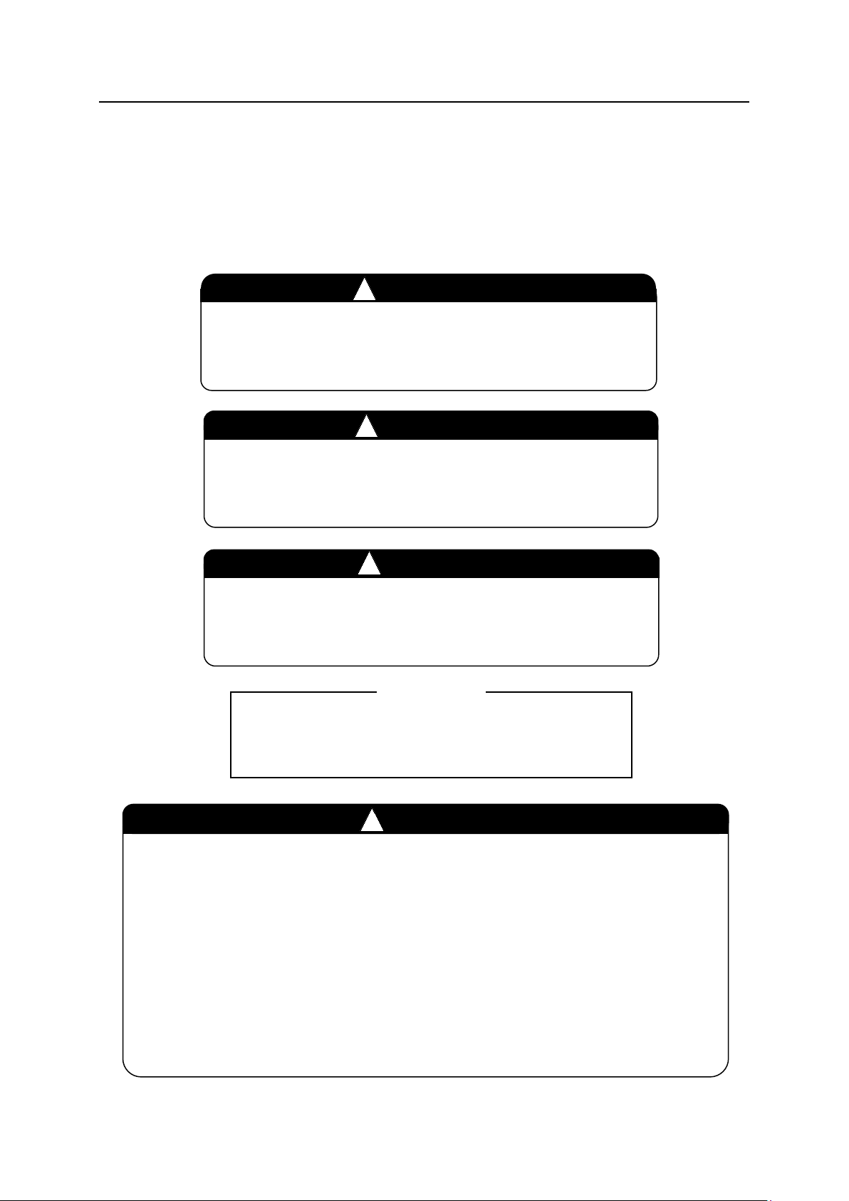
The items that require special attention in this manual are designated with the following symbols.
Ensure proper and safe operation of the robot and prevent physical injury or property damages by
complying with the safety matters given in the boxes with these symbols.
Failure to comply with indicated matters can result in
imminent injury or death.
Failure to comply with indicated matters may possibly lead
to injury or death.
Failure to comply with indicated matters may lead to
physical injury and/or mechanical damage.
Denotes precautions regarding robot specification,
handling, teaching, operation, and maintenance.
DANGER
WARNING
CAUTION
[NOTE]
1. The accuracy and effectiveness of the diagrams, procedures, and detail
explanations given in this manual cannot be confirmed with absolute
certainty. Accordingly, it is necessary to give one’s fullest attention when
using this manual to perform any work.
2. Safety related contents described in this manual apply to each individual
work and not to all robot work. In order to perform every work in safety,
read and fully understand “Safety Manual”, all pertinent laws, regulations
and related materials as well as all the safety explanations described in each
chapter, and prepare safety measures suitable for actual work.
WARNING
ii
Page 4

F Series Controller Safety
!
Kawasaki Robot Installation and Connection Manual - Arc Welding Application -
Safety
When installing and connecting the Arc Welding Robot, carefully read the following precautions
together with the safety precautions in the “Installation and Connection Manual” for Robot Arm
and Controller.
Installation Environment of Robot Arm
1. Install the safety fence in consideration of not only the motion range of the robot arm but also
the distance that protects operators/personnel from any possible exposure to arc spatter.
2. Provide light shield in order to protect operators/personnel from arc burning and eye injury
caused by direct viewing of arc beam.
3. Do not put any flammable/combustible materials around the Arc Welding Robot.
Installation of the Robot Arm
1. Be sure to isolate the robot arm from the torch and welding wires.
Installation and Connection of Controller
1. Provide an external power switch exclusively for the robot. Do not share the switch with the
welder and other equipment.
2. Use the dedicated ground (100 Ω or less). Never share the ground with welder, etc. for
grounding wire or grounding electrode.
3. Never wire the motor cable and the signal cable through under the welder.
4. To avoid influence by electromagnetic noises generated from welding arc, install precision
equipment, etc. away from welding arc and supply input power separately.
CAUTION
When there is equipment which generates high levels of noise, such as
electromagnetic contactors, brakes, solenoids and induction motors, around the
installation site, attach an appropriate surge killer to them to prevent from
generating the noise.
iii
Page 5
F Series Controller Safety
!
!
Kawasaki Robot Installation and Connection Manual - Arc Welding Application -
Cable Connection
Strictly observe the following precautions when connecting the robot arm with the robot
controller.
Do not connect the primary power before connection between the robot and robot
controller. Otherwise, there is a possibility of electrical shock.
1. Be careful not to misconnect cables when connecting the cables. Forcible
connection of cables may result in damage to connectors or break in the
electrical system.
2. Do not step on the motor and signal cables or put objects on them. In
addition, place the motor and signal cables where personnel or vehicles do
not step on. If the motor and signal cables are stepped on, damage on the
cables and failure in electrical system may occur.
3. Separate the harness from any nearby high voltage lines (min. 1 m apart). Do
not bundle or run the harnesses in parallel with other power lines. The noise
generated from power lines will cause malfunctions.
WARNING
CAUTION
iv
Page 6
F Series Controller Safety
!
!
Kawasaki Robot Installation and Connection Manual - Arc Welding Application -
Primary Power Connection
Prior to connecting the primary power, confirm that the primary power supply
for the controller is cut off. To prevent primary power from being turned ON
accidentally, tag the breaker and indicate clearly that work is in progress, or
assign a supervisor to prevent accidents caused when someone accidentally turns
ON the breaker until all the connections are complete. Connecting components
while power is supplied is extremely dangerous and may cause electric shock.
1. Connect with ground to prevent electrical noise and shock without fail.
2. Use a dedicated ground (100 Ω or less) and connect via the ground wire
whose size is larger than that of the recommended cable size shown below (3.5
to 8 mm2).
3. Never share the ground with welder, etc. for grounding wire or minus pole
(base material).
DANGER
WARNING
4. When using the minus pole of the weld power supply (base material) for arc
welding, etc., connect it to a jig or directly to base metal. Do not share the
ground with the robot and the robot controller, and isolate without fail.
5. Prior to turning ON the primary power to controller, make sure the power
supply is connected and all the covers are reattached properly without fail.
Failure to do so may cause electrical shock.
v
Page 7

F Series Controller Safety
!
Kawasaki Robot Installation and Connection Manual - Arc Welding Application -
1. Prepare primary power that meets the specifications of the controller in
terms of momentary power interruption, voltage fluctuation, power capacity,
etc. If the power is interrupted or the voltage goes out of the controller’s
specified range (above/below ratings) instantaneously, then the power
monitoring circuit activates cutting off the power, and an error is returned.
2. If the primary power may emits electrical noises, set up a noise filter to
reduce the noise level.
3. Provide a primary power switch (breaker) exclusively for the robot, do not
share the switch with welder, etc.
4. To prevent electrical leakage, attach a breaker with anti-leak specification on
the primary power switch. (Use a Time Delay Relay with sensitivity of 100
mA or more.)
CAUTION
vi
Page 8

F Series Controller Safety
Kawasaki Robot Installation and Connection Manual - Arc Welding Application -
Connection with Welding Equipment
1. Use only the welding cable with no damages.
2. Use and handle the gas cylinders with caution.
3. Firmly fix the gas cylinders so as not to fall over.
4. Use only the gas hose and water-cooling torch hose with no damages.
5. Conduct gas and water piping without gas or water leakage.
6. When using a gas flowmeter, check if it is for gas cylinders or for the factory piping, and use
the appropriate flow meter.
Arc Welding Work
1. Enclose the source of arc ray with welding screen/plate. Arc rays can injure eyes and burn
skin. Never look at the arc ray directly.
2. All operators and supervisors must wear welding glasses or masks with sufficient protection
grade to protect their eyes from arc ray, spatter and slag or filler wires.
3. Use suitable welding curtain to protect the eyes of nearby persons from the arc rays.
4. Always wear welding glasses in a welding area.
5. Wear appropriate protective clothing such as leather gloves, long-sleeve shirts, leggings,
leather apron, etc. in order to avoid burns caused by hot workpieces after welding and by
spatter and slag.
6. Do not use flammable materials such as paint, grease, etc. near the welding area.
7. Remove flammables and combustibles well away from the welding area.
8. Always have someone watch for fire.
9. Use enough ventilation to keep hazardous fumes and gases away from the breathing zone.
10. When welding, keep your head as far away as possible from the fume to minimize the
amount of fume inhaled.
11. To prevent intoxication or to eliminate possible oxygen deficiency, supply adequate
ventilation by an exhaust system located as close to the work area as possible or by
respiratory protection per pertinent laws and regulations, such as Industrial Safety and Health
Law, Ordinance on Prevention of Hazards due to Dust.
12. Properly insulate and ground each of the required devices according to instructions for each
device.
13. Electric arc welding produces electromagnetic field which may have bad influences on the
pacemaker. Therefore, persons with pacemakers should not go near welding operations until
they have consulted their doctor.
14. The electromagnetic noise produced in arc welding may cause malfunction of peripheral
devices without noise protection.
vii
Page 9

F Series Controller Safety
Kawasaki Robot Installation and Connection Manual - Arc Welding Application -
15. When using the I/O function of the arm ID board together with high frequency equipment,
avoid close parallel runs and overlapping runs of the coaxial power cable and the I/O cable to
keep electrical noise from affecting the wiring.
16. Use the laser sensor in accordance with the instructions from the manufacturer when using
laser welder, laser sensor and so on.
17. Incorrect usage of laser devices may result in severe injuries. Especially, take proper eye
safety precautions, since there is a risk for blindness. Laser beams may also burn skin,
clothing or ignite surrounding volatile substances such as alcohol.
viii
Page 10

F Series Controller Table of Contents
Kawasaki Robot Installation and Connection Manual - Arc Welding Application -
Table of Contents
Preface ··········································································································· i
Symbols ········································································································ ii
Safety ·········································································································· iii
Work Flow at Installation and Connection of Arc Welding Robot····································· xi
1 Mounting and Connection of Wire Feeding Unit ················································· 1
1.1 RA06L, RA10N ······················································································· 1
1.1.1 Installation ON Wall/Ceiling ········································································ 1
1.1.2 Installation on Floor/Shelf ··········································································· 1
1.2 RA05L ·································································································· 3
1.2.1 Installation on Wall/Ceiling ········································································· 3
1.2.2 Installation on Floor/Shelf ··········································································· 3
2 Mounting of Welding Torch and Connection of Coaxial Power Cable ······················· 4
2.1 Mounting Non-Kawasaki Shock Sensor on Wrist Flange ······································· 4
2.2 RA06L, RA10N ······················································································· 5
2.2.1 Mounting of Shock Sensor and Torch Mounting Bracket ······································· 5
2.2.2 Mounting of Torch Gauge (Option) ································································ 6
2.2.3 Torch Adjustment Method ··········································································· 7
2.2.4 Connection of Coaxial Power Cable ······························································· 8
2.2.5 Cutting the Liner ···················································································· 10
2.2.6 Liner Clamp Function ·············································································· 11
2.3 RA05L ································································································ 12
2.3.1 Mounting of Shock Sensor and Torch Mounting Bracket ····································· 12
2.3.2 Mounting of Torch Gauge (Option) ······························································ 13
2.3.3 Torch Adjustment Method ········································································· 14
2.3.4 Connection of Coaxial Power Cable ····························································· 16
2.3.5 Cutting the Liner ···················································································· 17
2.3.6 Liner Clamp Function ·············································································· 18
3 Grounding Method ·················································································· 19
4 Connection with Welding Equipment ···························································· 20
4.1 RA06L, RA10N ····················································································· 21
4.2 RA05L ································································································ 22
5 Arc Welding Interface Board (2AN) Installation Procedure ·································· 23
5.1 Installing on OP1 ···················································································· 23
5.2 Installing on OP2 ···················································································· 26
ix
Page 11

F Series Controller Table of Contents
Kawasaki Robot Installation and Connection Manual - Arc Welding Application -
Appendix 1 Connection Diagram with Welder (DM-350) ··········································· 29
Appendix 2 Arc Welding Interface Board ······························································ 31
Appendix 3 Deformation of Welding Torch and Replacement ····································· 35
x
Page 12
F Series Controller Work Flow at Installation and Connection of Arc Welding Robot
Kawasaki Robot Installation and Connection Manual - Arc Welding Application -
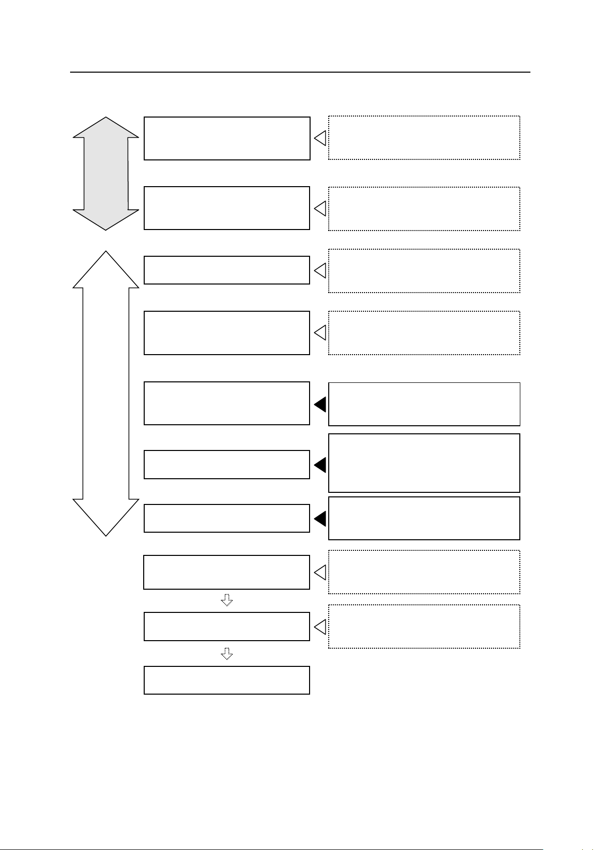
Work Flow at Installation and Connection of Arc Welding Robot
Examine location and prepare for
installation of robot arm.
Refer to “Installation and Connection
Manual” for Robot Arm.
Preparation
Examine location and prepare for
installation of controller.
Refer to “Installation and Connection
Manual” for Controller.
Transport and install robot arm.
Refer to “Installation and Connection
Manual” for Robot Arm.
Transport and install controller
and connect primary power.
Refer to “Installation and Connection
Manual” for Controller.
Actual Work
Mount and connect wire feeder
motor and gas valve.
Refer to “1 Mounting and Connection
of Wire Feeding Unit”.
Mount welding torch.
Refer to “2 Mounting of Welding
Torch and Connection of Coaxial
Power Cable”.
Connect to welding equipment.
Refer to “4 Connection with Welding
Equipment”.
Fine adjust welding torch
position.
Check other functions.
Work complete
Refer to “Operation Manual” and “Arc
Welding Operation Manual”.
Refer to “Operation Manual” and “Arc
Welding Operation Manual”.
xi
Page 13
F Series Controller 1 Mounting and Connection of Wire Feeding Unit
!
Kawasaki Robot Installation and Connection Manual - Arc Welding Application -
1 Mounting and Connection of Wire Feeding Unit
This manual describes how to mount and connect the wire feeding unit, taking a DAIHEN (OTC)
wire feeder CMRE-742 as an example. For other wire feeders, give due consideration or contact
Kawasaki.
1. Before starting mounting of wire feeder motor and gas valve, move the robot
arm to a place where the work can be done easily and turn OFF the motor
power and the controller po w e r.
2. Keep isolation between the wire feeder motor and the robot arm by bakelite
board etc. without fail. Otherwise welding current might short to the robot
arm due to the isolation failure.
1.1 RA06L, RA10N
1.1.1
The wire feeding unit mounting location on a wall-mounted or ceiling-mounted robot depends on
the operation conditions. Carry out an appropriate installation procedure in consideration of the
workpiece and other obstacles.
Installation on Wall/Ceiling
WARNING
1.1.2
Follow the procedures below to mount wire feeding unit on the shoulder part of arm. The fixing
brackets are separately required for mounting. Be sure to use them.
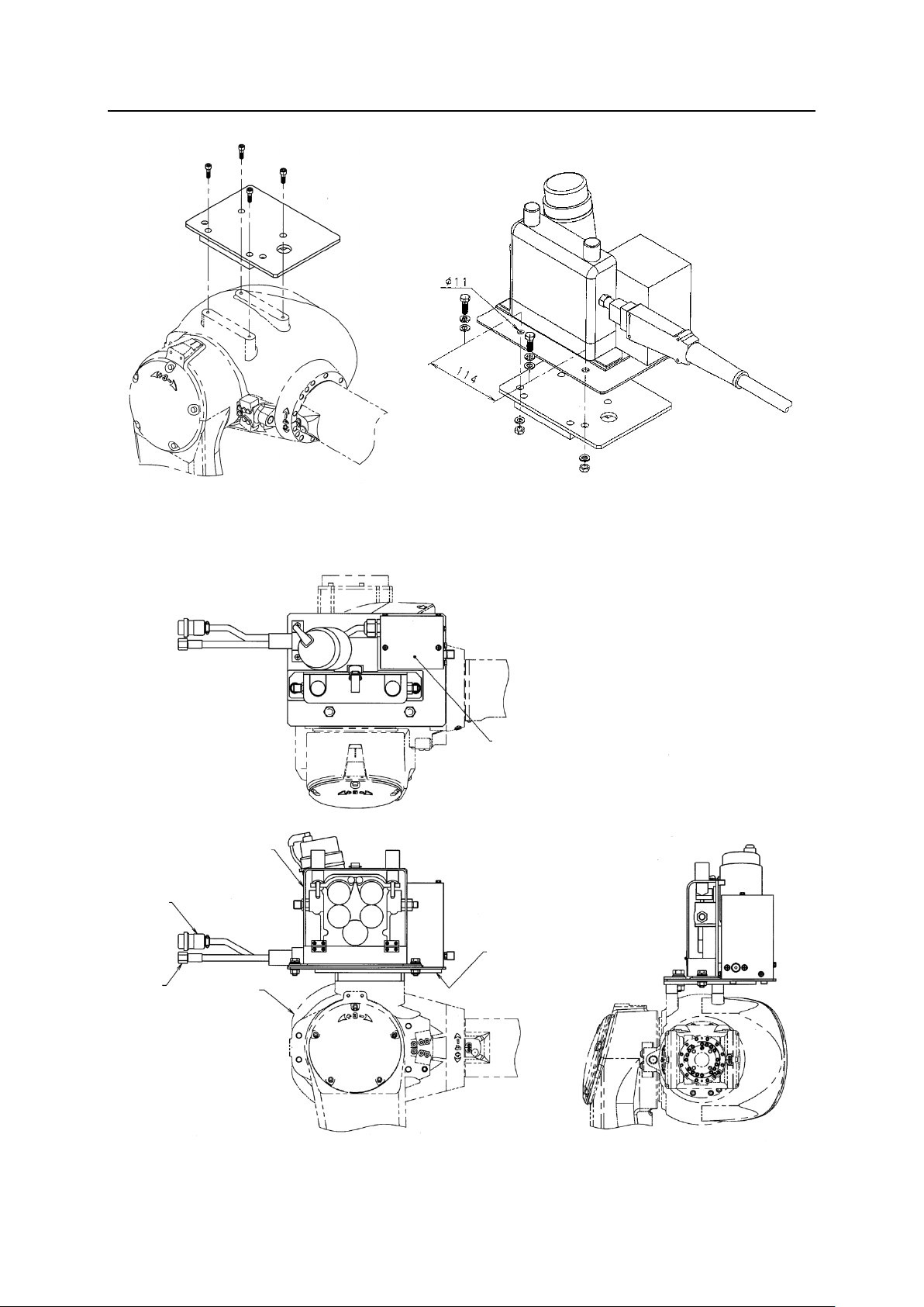
1. Referring to Fig. 1.1, mount the fixing bracket onto the shoulder part of arm.
2. Referring to Fig. 1.2, mount the wire feeding unit to the fixing bracket. For mounting, use the
3. Referring to Fig. 1.3, connect control cable (the motor cable, the encoder cable and the
Installation on Floor/Shelf
hexagon head bolts and washers and nuts provided with the wire feeding unit.
voltage detection cable) connector of wire feeding unit with the specified connector.
[NOTE]
A shock sensor connector is included in the arm.
1
Page 14
F Series Controller 1 Mounting and Connection of Wire Feeding Unit
Fig. 1.1 Mounting of fixing bracket
(Procedure 1)
Fig. 1.2 Mounting of wire feeding unit
(Procedure 2)
Kawasaki Robot Installation and Connection Manual - Arc Welding Application -
Control cable
Gas hose
Wire feeding unit
Arm
Fig. 1.3 Connection of control cable connector (Procedure 3)
Solenoid valve
(built-in)
Fixing bracket
2
Page 15

F Series Controller 1 Mounting and Connection of Wire Feeding Unit
Kawasaki Robot Installation and Connection Manual - Arc Welding Application -
1.2
RA05L
1.2.1
The wire feeding unit mounting location on a wall-mounted or ceiling-mounted robot depends on
the operation conditions. Carry out an appropriate installation procedure in consideration of the
workpiece and other obstacles.
1.2.2
For RA05L, the wire feeding unit cannot be mounted on the arm. Accordingly, mount it
separately from the arm by yourself with consideration of workpieces and other obstacles. (See
Fig. 1.2 as a reference when mounting it.)
Installation on Wall/Ceiling
Installation on Floor/Shelf
3
Page 16

F Series Controller 2 Mounting of Welding Torch and Connection of Coaxial Power Cable
!
Kawasaki Robot Installation and Connection Manual - Arc Welding Application -
2 Mounting of Welding Torch and Connection of Coaxial Power Cable
Before mounting the welding torch, move the robot arm to a place where work
can be done easily and turn OFF the motor power and the controller power of the
robot controller. When replacing/mounting a welding torch that is connected to
the welder, turn OFF the power to the welder before starting the work without
fail.
2.1
Mounting Non-Kawasaki Shock Sensor on Wrist Flange
1. Mount a torch holder and welding torch whose total weight is within the load capacity of the
robot, specified in separate “Installation and Connection Manual” for Robot Arm.
2. Keep isolation between wrist flange and welding torch without fail.
WARNING
4
Page 17

F Series Controller 2 Mounting of Welding Torch and Connection of Coaxial Power Cable
Kawasaki Robot Installation and Connection Manual - Arc Welding Application -
2.2
RA06L, RA10N
2.2.1
Mounting of Shock Sensor and Torch Mounting Bracket
Parallel pin
Torch mounting bracket ASSY
Insulating bracket
Shock sensor
Hexagon socket
head cap screw
Output flange
Mount
Hexagon socket
head cap screw
L bracket
Hexagon socket
head cap screw
Hexagon socket
Welding torch
Hexagon socket
head cap screw
head cap screw
Tightening Torque: 8.0 N⋅m
Tip gauge (option)
Tightening Torque: 7.0 N⋅m
Fig. 2.1 Mounting of torch and shock sensor
1. Mount the mount onto the output flange of arm with parallel pin (φ6×10) and 4 hexagon
socket head cap screws (M6×12).
2. Mount the L bracket to the mount with 2 hexagon socket head cap screws (M8×25).
3. Mount the insulating bracket to the L bracket with 2 hexagon socket head cap screws
(M8×20).
4. Mount the shock sensor onto the insulating bracket with 4 hexagon socket head cap screws
(M5×20).
5. Loosen the hexagon socket head cap screw of the shock sensor (M5×20) to insert and fix the
welding torch.
5
Page 18

F Series Controller 2 Mounting of Welding Torch and Connection of Coaxial Power Cable
Kawasaki Robot Installation and Connection Manual - Arc Welding Application -
2.2.2
Mounting of Torch Gauge (Option)
Reference
point
Hexagon
socket head
cap screw
Detail
drawing
Without tip gauge
Detail drawing
Reference
point
Torch gauge
ASSY
(Option)
Tip gauge
(Option)
Fig. 2.2 Mounting of torch gauge
1. Remove the nozzle and the contact tip from the torch.
2. Mount the tip gauge to the torch firmly.
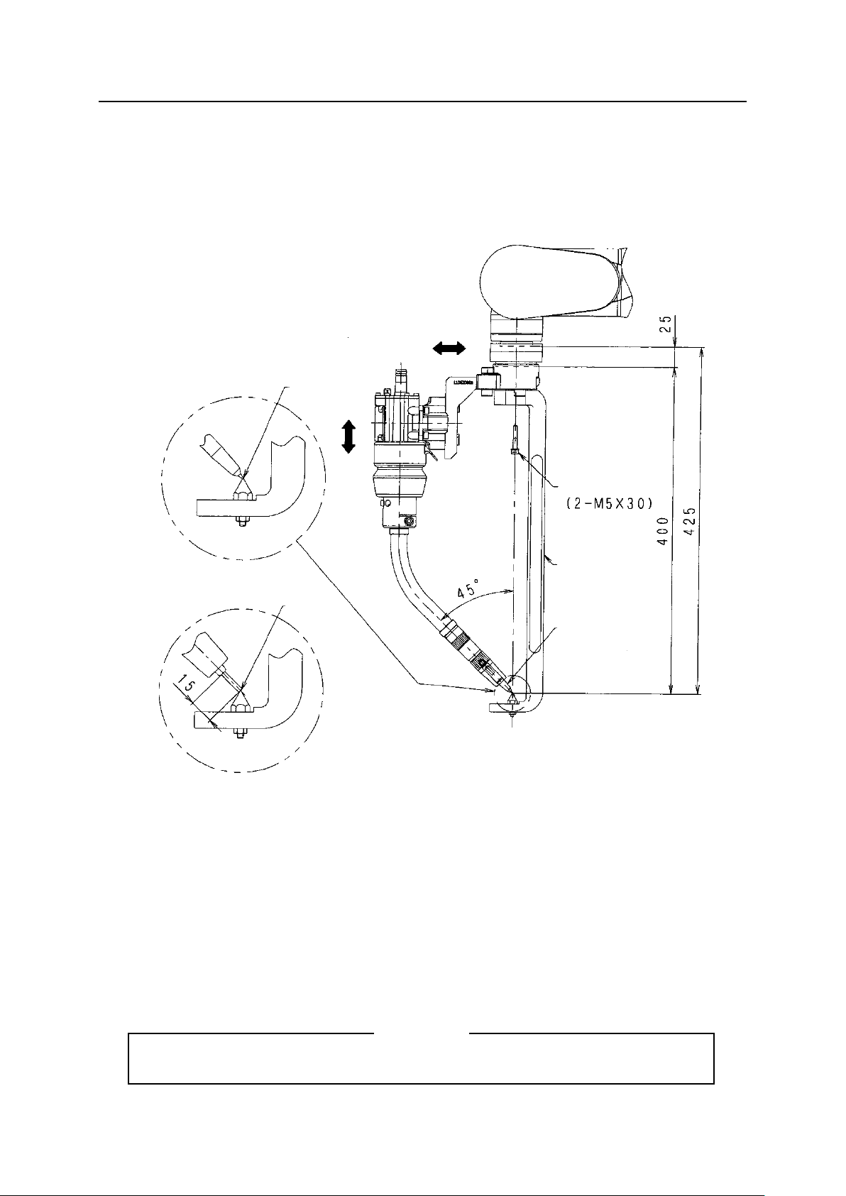
3. Mount the torch gauge ASSY using 2 hexagon socket head cap screws (M5×30) attached
with the torch gauge ASSY.
4. Make sure that the reference point of the torch gauge coincides with the tip gauge end. If not,
adjust the end position of the tip gauge so that its end coincides with the reference point of
the torch gauge. (Refer to “2.2.3 Torch Adjustment Method” for torch adjustment method.)
[NOTE]
When the tip gauge is not used, adjust the torch by wire cut to a specified length, etc.
6
Page 19

F Series Controller 2 Mounting of Welding Torch and Connection of Coaxial Power Cable
Kawasaki Robot Installation and Connection Manual - Arc Welding Application -
2.2.3
Torch Adjustment Method
L-bracket
Insulating
bracket
Nozzle holder ASSY
Left Right
Up
Down
Feeding cable
Hood
Tip gauge
Back
Front
Mount
Reference
point
Fig. 2.3 Torch adjustment method
1. If the torch end deviates in vertical direction, loosen 2 hexagon socket head cap screws ①
(M8×20) that fix the insulating bracket onto the L bracket. Correct the position, moving the
torch end in the direction that the torch end deviates (upward or downward), and then fix it
firmly by tightening the hexagon socket head cap screws.
2. If the torch end deviates in front-back direction, loosen 2 hexagon socket head cap screws ②
that fix the mount onto the L bracket (M8×25). Correct the position, moving the torch end in
the direction in which the torch end deviates (backward or forward), and then fix it firmly by
tightening the hexagon socket head cap screws.
3. If the torch end deviates in horizontal direction, adjust in the following procedure referring to
the “Fig. 2.4 Adjustment method of torch (right/left direction)”.
(1) Remove the hood.
(2) Remove the hexagon socket head cap screw (M5×12) fixing feeding cable connected to
the nozzle holder ASSY.
(3) Loosen the hexagon socket head cap screw ③ (M5×20) and rotate the holder in the
proper direction (right/left direction) so that the deviation is eliminated.
(4) After fixing the nozzle holder and the feeding cable firmly, remount the hood.
7
Page 20

F Series Controller 2 Mounting of Welding Torch and Connection of Coaxial Power Cable
Remove the hood.
Unscrew the bolt fixing
Bolt for fixing a nozzle
Applicable arm
Cable length
Kawasaki Robot Installation and Connection Manual - Arc Welding Application -
Hood
feeding cable.
holder appears.
Nozzle holder ASSY
Fig 2.4 Adjustment method of torch (right/left direction)
2.2.4
Connection of Coaxial Power Cable
The coaxial power cable is used to lead the wire, shield gas and shock sensor cable from the wire
feeding unit to the torch. Refer to the Table 2.1 below to select the coaxial power cable according
to the arm.
Liner
Shock sensor cable
Table 2.1 Types of coaxial power cables
RA06L 1.3 m
RA10N 1.1 m
(Cable length)
Power cable
Gas hose
Fig. 2.5 Outline drawing of the coaxial power cable
8
Page 21

F Series Controller 2 Mounting of Welding Torch and Connection of Coaxial Power Cable
Kawasaki Robot Installation and Connection Manual - Arc Welding Application -
Shock sensor cable
Coaxial power cable
Faston
terminal
Hexagon
socket
Shock sensor cable
head
cap screw
(M5)
Shock sensor cable
Connector
Coaxial power cable
Faston terminal
Shock sensor (when using 50378-1002 type)
Gas hose
(Power
cable)
Fig. 2.6 Connection of the coaxial power cable
Protect the FASTON terminal of the shock sensor cable with the silicon glass tube supplied with
the coaxial power cable, and then fix it to the coaxial power cable with the tying band.
9
Page 22

F Series Controller 2 Mounting of Welding Torch and Connection of Coaxial Power Cable
Table 2.2 Cut length of liner from
(model)
DAIHEN torch
(model)
L (mm)
RT3500S
128
RT3500H
197
RT3500L
168
RT5000S
111
RT5000H
180
RT5000L
151
RTW5000S
124
RTW5000H
193
RTW5000L
174
RZ3500S
44
RZ3500H
115
RZ3500L
100
一線式パワーケーブル
ライナ
ライナ
ノズルホルダ
Kawasaki Robot Installation and Connection Manual - Arc Welding Application -
2.2.5
Cutting the Liner
Cut the liner according to the length of each torch, referring to Fig. 2.7, Fig. 2.8, Table 2.2 and
Table 2.3. Rasp the edge of the liner’s cut section to eliminate burrs, etc. Also, take enough care
not to bend a liner or burr the hole when cutting.
coaxial power cable (rough)
DAIHEN torch
L (mm)
RT3500S 291
RT3500H 360
RT3500L 331
RT5000S 274
RT5000H 343
RT5000L 314
Liner
Coaxial power cable
RTW5000S 288
Fig.2.7 Cut length of liner from coaxial power cable
RTW5000H 356
Liner
Fig.2.8 Cut length of liner from nozzle holder
RTW5000L 338
RZ3500S 207
RZ3500H 277
RZ3500L 263
Table 2.3 Cut length of liner from
nozzle holder (rough)
Nozzle holder
10
Page 23

F Series Controller 2 Mounting of Welding Torch and Connection of Coaxial Power Cable
Kawasaki Robot Installation and Connection Manual - Arc Welding Application -
2.2.6
Liner Clamp Function
A liner clamp is equipped with the nozzle holder of each shock sensor.
During welding, weld wire may become floppy and it causes unstable wire feeding depending on
clearance between the sensor and the liner in the coaxial power cable. This problem will result in
faulty weld arc start or fluctuations in the protrusion length of weld wire.
The liner clamp unit has the effect of reducing the behavior of weld wire by binding the coil liner.
1. Loosen the lock nut, and then thoroughly pull out the clamp screw.
2. Insert the coaxial power cable.
3. Gradually turn the clamp screw until it hits against the liner, and then make it 1/4 turns.
4. Clamp the liner with the lock nut.
[NOTE]
1. Turning the clamp screw excessively will damage the liner and disables weld
wire feeding.
2. To remove the coaxial power cable or the liner, unclamp the liner clamp first.
Liner clamp
Clamp screw
Lock nut
Fig. 2.9 Liner clamp
11
Page 24

F Series Controller 2 Mounting of Welding Torch and Connection of Coaxial Power Cable
Kawasaki Robot Installation and Connection Manual - Arc Welding Application -
2.3
RA05L
2.3.1
Mounting of Shock Sensor and Torch Mounting Bracket
Parallel pin
Hexagon socket head cap screw
Parallel pin
Torch mounting bracket ASSY
Insulating bracket
Shock sensor
Output flange
Adaptor plate 2
Parallel pin
Adaptor plate 1
Hexagon socket
head cap screw
Mount
Hexagon socket
head cap screw
L bracket
Hexagon socket
head cap screw
Hexagon socket
head cap screw
Welding torch
Hexagon socket
head cap screw
Hexagon
socket head
cap screw
Tightening Torque: 8.0 N⋅m
Tip gauge (option)
Tightening Torque: 7.0 N⋅m
Fig. 2.10 Mounting of torch and shock sensor
1. Mount the adaptor plate 2 onto the output flange of arm with parallel pin (φ5×12) and 4
hexagon socket head cap screws (M5×12).
2. Mount the adaptor plate 1 onto the adaptor plate 2 with parallel pin (φ6×10) and 4 hexagon
socket head cap screws (M5×16).
3. Mount the mount onto the adaptor plate 1 with parallel pin (φ6×12) and 4 hexagon socket
head cap screws (M6×12).
4. Mount the L bracket to the mount with 2 hexagon socket head cap screws (M8×25).
5. Mount the insulating bracket to the L bracket with 2 hexagon socket head cap screws
(M8×20).
6. Mount the shock sensor onto the insulating bracket with 4 hexagon socket head cap screws
(M5×20).
12
Page 25
F Series Controller 2 Mounting of Welding Torch and Connection of Coaxial Power Cable
Kawasaki Robot Installation and Connection Manual - Arc Welding Application -
7. Loosen the hexagon socket head cap screw of the shock sensor (M5×20) to insert and fix the
welding torch.
2.3.2
Mounting of Torch Gauge (Option)
Reference
point
Detail
drawing
Reference
point
Hexagon socket
head cap screw
Torch gauge ASSY
(Option)
Tip gauge
(Option)
Without tip gauge
Detail drawing
Fig. 2.11 Mounting of torch gauge
1. Remove the nozzle and the contact tip from the torch.
2. Mount the tip gauge to the torch firmly.
3. Mount the torch gauge ASSY using 2 hexagon socket head cap screws (M5×30) attached
with the torch gauge ASSY.
4. Make sure that the reference point of the torch gauge coincides with the tip gauge end. If not,
adjust the end position of the tip gauge so that its end coincides with the reference point of the
torch gauge. (Refer to “2.3.3 Torch Adjustment Method” for torch adjustment method.)
[NOTE]
When the tip gauge is not used, adjust the torch by wire cut to a specified length, etc.
13
Page 26

F Series Controller 2 Mounting of Welding Torch and Connection of Coaxial Power Cable
Kawasaki Robot Installation and Connection Manual - Arc Welding Application -
2.3.3
Torch Adjustment Method
L-bracket
Insulating bracket
Mount
Reference
point
Nozzle holder ASSY
Left
Up
Down
Hexagon socket
head cap screw
(M5X12)
Feeding cable
Right
Hood
Back
Tip gauge
Fig. 2.12 Torch adjustment method
Front
1. If the torch end deviates in vertical direction, loosen 2 hexagon socket head cap screws ①
(M8×20) that fix the insulating bracket onto the L bracket. Correct the position, moving the
torch end in the direction that the torch end deviates (upward or downward), and then fix it
firmly by tightening the hexagon socket head cap screws.
2. If the torch end deviates in front-back direction, loosen 2 hexagon socket head cap screws ②
(M8×25) that fix the L bracket onto the mount . Correct the position, moving the torch end in
the direction in which the torch end deviates (backward or forward), and then fix it firmly by
tightening the hexagon socket head cap screws.
3. If the torch end deviates in horizontal direction, adjust in the following procedure referring to
the “Fig. 2.13 Adjustment method of torch (right/left direction)”.
(1) Remove the hood.
(2) Remove the hexagon socket head cap screw (M5×12) fixing feeding cable connected to
the nozzle holder.
14
Page 27

F Series Controller 2 Mounting of Welding Torch and Connection of Coaxial Power Cable
Remove the hood.
Unscrew the bolt fixing
Bolt for fixing a nozzle
Kawasaki Robot Installation and Connection Manual - Arc Welding Application -
(3) Loosen the hexagon socket head cap screw ③ (M5×20) fixing the nozzle holder and
rotate the holder in the proper direction (right/left direction) so that the deviation is
eliminated.
(4) After fixing the nozzle holder and the feeding cable firmly, remount the hood.
Hood
Fig 2.13 Adjustment method of torch (right/left direction)
feeding cable.
Nozzle holder ASSY
holder appears.
15
Page 28

F Series Controller 2 Mounting of Welding Torch and Connection of Coaxial Power Cable
Kawasaki Robot Installation and Connection Manual - Arc Welding Application -
2.3.4
Connection of Coaxial Power Cable
The coaxial power cable is used to lead the wire, shield gas and shock sensor cable from the wire
feeding unit to the torch. For RA05L, the wire feeding unit cannot be mounted on the arm. To
mount it separately, determine the length of the coaxial power cable.
Shock sensor cable
Coaxial power cable
Faston
terminal
Hexagon
socket head
cap screw
(M5)
Shock sensor cable
Shock sensor cable
Coaxial power cable
Faston terminal
Shock sensor (when using 50378-1002 type)
Connector
Gas hose
(Power
cable)
Fig. 2.14 Connection of the coaxial power cable
Protect the Faston terminal of the shock sensor cable with the silicon glass tube supplied with the
coaxial power cable, and then fix it to the coaxial power cable with the tying band.
16
Page 29

F Series Controller 2 Mounting of Welding Torch and Connection of Coaxial Power Cable
Table 2.4 Cut length of liner from
(model)
(model)
一線式パワーケーブル
ライナ
ライナ
ノズルホルダ
Kawasaki Robot Installation and Connection Manual - Arc Welding Application -
2.3.5
Cutting the Liner
Cut the liner according to the length of each torch, referring to Fig. 2.15, Fig. 2.16, Table 2.4 and
Table 2.5. Rasp the edge of the liner’s cut section to eliminate burrs, etc. Also, take enough care
not to bend a liner or burr the hole when cutting.
coaxial power cable
(rough)
DAIHEN torch
L (mm)
RT3500S 291
RT3500H 360
RT3500L 331
RT5000S 274
RT5000H 343
Liner
Fig.2.15 Cut length of liner from coaxial power cable
Coaxial power cable
Nozzle holder
RT5000L 314
RTW5000S 288
RTW5000H 356
RTW5000L 338
RZ3500S 207
RZ3500H 277
RZ3500L 263
Table 2.5 Cut length of liner from
nozzle holder (rough)
DAIHEN torch
L (mm)
RT3500S 128
RT3500H 197
RT3500L 168
RT5000S 111
RT5000H 180
Liner
Fig. 2.16 Cut length of liner from nozzle holder
17
RT5000L 151
RTW5000S 124
RTW5000H 193
RTW5000L 174
RZ3500S 44
RZ3500H 115
RZ3500L 100
Page 30

F Series Controller 2 Mounting of Welding Torch and Connection of Coaxial Power Cable
Kawasaki Robot Installation and Connection Manual - Arc Welding Application -
2.3.6
Liner Clamp Function
A liner clamp is equipped with the nozzle holder of each shock sensor.
The liner clamp unit has the effect of reducing the behavior of weld wire by binding the coil liner.
1. Loosen the lock nut, and then thoroughly pull out the clamp screw.
2. Insert the coaxial power cable.
3. Gradually turn the clamp screw until it hits against the liner, and then make it 1/4 turns.
4. Clamp the liner with the lock nut.
[NOTE]
1. Turning the clamp screw excessively will damage the liner and disables weld wire
feeding.
2. To remove the coaxial power cable or the liner, unclamp the liner clamp first.
Liner clamp
Clamp screw
Lock nut
Fig.2.17 Liner clamp
18
Page 31
F Series Controller 3 Grounding Method
!
Kawasaki Robot Installation and Connection Manual - Arc Welding Application -
3 Grounding Method
WARNING
1. Never share the ground among the robot controller, robot arm, welder, other
equipment and etc.
2. For the controller and robot arm, use a dedicated ground (100 Ω or less) as
the ground line shown below.
3. If grounding and insulation of the controller and the robot arm are
insufficient, malfunction caused by noise from ground lines, breakage or
electrical shock may occur. Accordingly, strictly observe below. In addition,
make sure that the controller and the robot are connected with dedicated
ground lines and check that they are isolated from other equipment and
devices via a circuit tester, etc.
Robot controller : 3.5 mm2 (AWG #12)
Robot arm : 3.5 mm2 (AWG #12)
For the multi axes robot, use a ground line whose size is larger than that of the power supply line.
Isolate the wire feeding unit and welding torch from the robot arm using Bakelite etc. (Refer to
“Safety” in this manual.)
Grounding is extremely important to prevent noise and electrical shock, etc. Connect the
grounding wire by the method shown in the Fig. 3.1.
Arm
Welder
Controller
Base material
Welding work table
Connect in as close contact
as possible with welding part
of workpiece.
350A model:
2
or more
14 mm
500A model:
2
or more
22 mm
3.5 mm2 or
more
Connect the ground
directly to the robot arm.
3.5 mm2 or more
Connect the ground directly to
the welding work table.
Welding torch
Fig. 3.1 For RA05L, RA06L and RA10N
19
Page 32

F Series Controller 4 Connection with Welding Equipment
!
Kawasaki Robot Installation and Connection Manual - Arc Welding Application -
4 Connection with Welding Equipment
1. Before connecting the robot arm with welding equipment, move the robot
arm to a place where the work can be done easily. Then turn OFF the motor
power and the controller power.
2. Before connecting the robot arm with welding equipment, turn OFF the
welder power supply without fail.
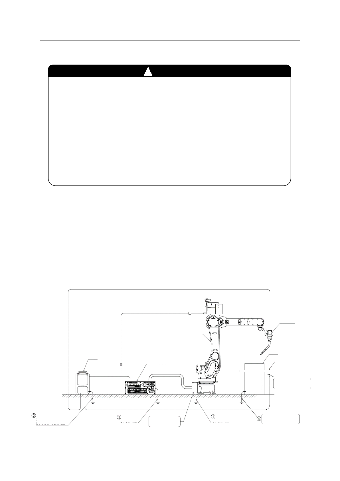
An example of connection to an arc welder, etc. is shown below. For details of handling and
connection of power cables, etc. to the welder, refer to its instruction manual.
1. Connect the arc welding interface board in the controller (Refer to “Appendix 2 Arc Welding
Interface Board”.) to the welder via the I/F cable.
2. For CO2 welding, a heater and gas flowmeter are normally connected to the gas cylinder.
Non-heater type gas cylinder is also available. If a factory piping is used instead of cylinders,
connect a flowmeter designed for factory piping.
3. Connect welding cable (ground) on the base material with the welding work table.
WARNING
4. For the wire feeding unit, a reel type machine is shown in the figure. However, when a pack
is used, connect the wire feeding unit with the pail pack.
20
Page 33

F Series Controller 4 Connection with Welding Equipment
Kawasaki Robot Installation and Connection Manual - Arc Welding Application -
4.1
RA06L, RA10N
Conduit cable
Wire reel
Welding cable on base
material side(ground)
Wire feeding unit
Robot arm
Coaxial power cable
Shock sensor cable
Shock sensor
Welding torch
Base material
Welding work table
Gas flowmeter
Heater
Separate harness
Gas cylinder
Welding cable on torch side (+)
Fig. 4.1 Welding equipment connection example (DAIHEN welder DM-350)
Controller
Control cable
Welding cable on base
material side (ground)
Welder
I/F cable
21
Page 34

F Series Controller 4 Connection with Welding Equipment
Kawasaki Robot Installation and Connection Manual - Arc Welding Application -
4.2
RA05L
Wire reel
Gas hose
Wire feeding unit
Coaxial power cable
Shock sensor cable
Shock sensor
Robot arm
Welding torch
Base material
Welding work table
Gas flowmeter
Heater
Welding cable on
base material side
(ground)
Separate harness
Gas cylinder
Welding cable on torch side (+)
Controller
Control cable
I/F cable
Fig. 4.2 Welding equipment connection example (DAIHEN welder DM-350)
22
Page 35

F Series Controller 5 Arc Welding Interface Board (2AN) Installation Procedure
No.
Part number
Part name
Remarks
Plate to secure the
Kawasaki Robot Installation and Connection Manual - Arc Welding Application -
5 Arc Welding Interface Board (2AN) Installation Procedure
This chapter explains the procedure for installing the arc welding interface board (2AN) on the
F60 controller.
5.1
Installing on OP1
1. The following table lists the parts required to install the arc welding interface board.
Check to make sure that you have the correct parts before installing them on the controller.
1 49094-0551 2AN board set
1-1 50999-0719
Arc welding interface
board (2AN)
Components of 1
1-2 60835-3582
optional board
1-3 50977-4835LA0 Optional board harness
1-4 60302-1296 Fixing screw To secure the board x 3
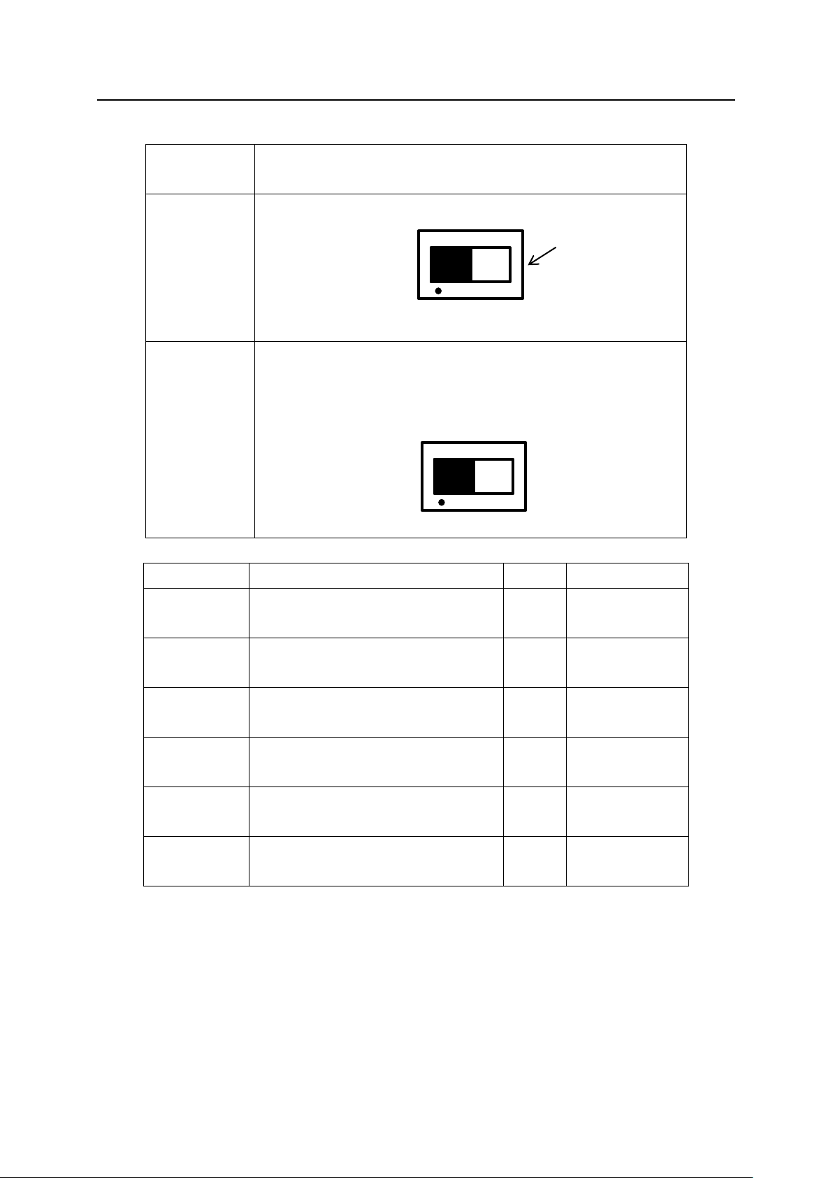
2. Make sure that the controller power is turned OFF.
3. Remove the countersunk screw, and remove the slot cover from OP1.
Screwed on with one countersunk screw
OP1 slot cover
4. Remove the screw, and detach the fixing metal plate and the slot cover.
Fixing metal plate
Screwed on with one screw
23
OP1 slot cover
Page 36

F Series Controller 5 Arc Welding Interface Board (2AN) Installation Procedure
Kawasaki Robot Installation and Connection Manual - Arc Welding Application -
5. Secure the 2AN board onto the fixing metal plate with a screw, instead of the slot cover.
6. Attach the plate to secure the optional board to the 2AN board with two screws.
Screwed on with
two screws
Plate to secure the optional board
7. Install the 2AN board to which the fixing plate was attached in step 6 on the controller with
one countersunk screw and one screw removed in step 3.
Countersunk
screw
Screw
24
Page 37

F Series Controller 5 Arc Welding Interface Board (2AN) Installation Procedure
Kawasaki Robot Installation and Connection Manual - Arc Welding Application -
8. Connect the optional board harness.
Optional board harness (EXIO-CN1)
25
Page 38

F Series Controller 5 Arc Welding Interface Board (2AN) Installation Procedure
Kawasaki Robot Installation and Connection Manual - Arc Welding Application -
5.2
Installing on OP2
1. Check to make sure that correct parts are selected before installing them on the controller.
2. Make sure that the controller power is turned OFF.
3. Remove the countersunk screw, and remove the slot cover from OP2.
Screwed on with one countersunk screw
OP2 slot cover
4. Remove the screw, and detach the fixing metal plate and the slot cover.
OP2 slot cover
Fixing metal plate
Screwed on with one screw
5. Secure the 2AN board onto the fixing metal plate with a screw, instead of the slot cover.
6. Attach the plate to secure the optional board to the 2AN board with two screws.
Screwed on with two screws
* The method is different from that of OP1
installation.
Plate to secure the optional board
26
Page 39

F Series Controller 5 Arc Welding Interface Board (2AN) Installation Procedure
Kawasaki Robot Installation and Connection Manual - Arc Welding Application -
7. Install the 2AN board to which the fixing plate was attached in step 6 on the controller with
one countersunk screw and one screw removed in step 3.
Countersunk
screw
Screw
27
Page 40

F Series Controller 5 Arc Welding Interface Board (2AN) Installation Procedure
Kawasaki Robot Installation and Connection Manual - Arc Welding Application -
8. Connect the optional board harness.
• If 2AW or 2AH board is not installed on
OP1, connect EXIO-CN1.
• If 2AW or 2AH board is installed on
OP1, connect CN1 of CN2-OP2 on OP1.
Optional board harness
Optional board harness
!
CAUTION
Be sure to connect both ends of the optional board harness to the connector.
If one end of the optional harness is not connected, a serial communication
error may result.
28
Page 41

F Series Controller Appendix 1 Connection Diagram with Welder (DM-350)
Kawasaki Robot Installation and Connection Manual - Arc Welding Application -
Appendix 1 Connection Diagram with Welder (DM-350)
1. RA06L, RA10N
29
Page 42

F Series Controller Appendix 1 Connection Diagram with Welder (DM-350)
Kawasaki Robot Installation and Connection Manual - Arc Welding Application -
2. RA05L
30
Page 43

F Series Controller Appendix 2 Arc Welding Interface Board
Connector
No.
Analog voltage output for setting parameters (normally, for welding current)
(Setting range: -15 V to +15 V)
2
A1_COM_GND
GND for A1_COMMAND
Analog voltage output for setting parameters (normally, for welding current)
(Setting range: -15 V to +15 V)
4
A2_COM_GND
GND for A2_COMMAND
Analog voltage output for setting parameters (normally, for welding current)
(Setting range: -15 V to +15 V)
6
A3_COM_GND
GND for A3_COMMAND
Analog voltage output for setting parameters (normally, for welding current)
(Setting range: -15 V to +15 V)
8
A4_COM_GND
A4_COMMAND
9
ROBOT_READY_A
Contact closed when welding is ready (Output)
10
ROBOT_READY_B
11
WELDER_ERR_24V
+24 V power source for welder error detection signal
12
WELDER_ERR_GND
GND for welder error detection signal
13
WELDER_ERR
Welder error detection signal (Input)
14
FEED_ON_A
Contact closed while the wire feeder motor is running (Output)
15
WIRE_FWD_A
Contact closed while wire is being fed in the forward direction (Output)
16
WIRE_FWD_B
FEED_ON_A common
17
WIRE_REV_A
Contact closed while wire is being fed in the reverse direction (Output)
18
WIRE_REV_B
19
WELD_ON_A
Contact closed when welding starts (Output)
20
WELD_ON_B
21
GAS_ON_A
Contact closed when gas is supplied (Output)
22
GAS_ON_B
23
ARC_DETECT_24V
+24 V power source for arc generation detection
24
ARC_DETECT
+24 V input when arc generation is detected
25
ARC_DETECT_EPS_A
+24 V input when arc generation is detected (external power supply type)
26
ARC_DETECT_EPS_B
27
TORCH_SHORT_24V
+24 V power source for torch short circuit detection
28
TORCH_SHORT
+24 V input when torch short circuit is detected
29
WIRE_STICK_+
+15 V output when deposition is detected
30
WIRE_STICK_-
GND for WIRE_STICK_+
+24 V output when the wire hold signal is turned ON (for driving the
solenoid valve)
32
WIRE_HOLD_GND
GND for WIRE_HOLD
1
WELD_ON_C
Contact closed when welding starts (Output)
2
WELD_ON_D
3 WIRE_FWD_C
Contact closed while wire is being fed in the forward direction (Output)
4
WIRE_FWD_D
5 WIRE_REV_C
Contact closed while wire is being fed in the reverse direction (Output)
6
WIRE_REV_D
7
TOUCH_SENCE
+24 V output while touch sensing is being performed
8
TOUCH_SENCE_24V
+24 V power source for TOUCH_SENCE
9
TOUCH_SENCE_GND
GND for TOUCH_SENCE
10
WIRE_TOUCH
+24 V input when wire touching is detected
11
+16V
+16 V power source for current sensor
12
-16V
+16 V power source for current sensor
13
N.C. 14
N.C. 15
N.C.
16
N.C. 17
TORCH_LS_24V
+24 V power source for torch interference detection
18
TORCH_LS
+24 V input when torch interference is detected
Kawasaki Robot Installation and Connection Manual - Arc Welding Application -
Appendix 2 Arc Welding Interface Board
1. Connector specifications
Set each output load capacity to 3 µF or less.
Board
Pin No. Signal Name Function
1 A1_COMMAND
3 A2_COMMAND
5 A3_COMMAND
7 A4_COMMAND
XWELD(A)
DMC 0.5/16-G1-2.54
2AN board
31 WIRE_HOLD
XWELD(B)
DMC 0.5/9-G1-2.54
31
Page 44

F Series Controller Appendix 2 Arc Welding Interface Board
Connector
Content
Remarks (location)
board)
XWELD (A)
I/O port 1
Rear panel
XWELD (B)
I/O port 2
Rear panel
Kawasaki Robot Installation and Connection Manual - Arc Welding Application -
2. Appearance
LD3
LD4
LD5
LD2
LD1
LD6
LD10
LD9
LD8
LD7
CN1 Communication connector (to the servo board) Side surface of circuit board
CN2 Communication connector (to the extension I/O
Side surface of circuit board
32
Page 45
F Series Controller Appendix 2 Arc Welding Interface Board
Name
LED
Content
Color
Remarks
(#MCARE)
(2)
Error: OFF
Kawasaki Robot Installation and Connection Manual - Arc Welding Application -
Switch
Function
SW1 For the system
Button
A
B
SW2 WELDER_ERR signal common switching
• “PNP”: 24 V input common, SOURCE/PNP type
(standard)
• “NPN”: GND input common, SINK/NPN type
PNP
NPN
LD1
(#MON)
LD2
(DONA)
LD7
(DONA)
LD8
LD9
(#LCARE)
LD10
(#MON)
Extension I/O communication
enabled
Extension I/O communication
output enabled
Extension I/O communication
output enabled (D/A)
Extension I/O communication error
Extension I/O communication error
(1)
Extension I/O communication
enabled (D/A)
Green
Normal: ON
Error: OFF
Normal: ON
Green
Error: OFF
Normal: ON
Green
Error: OFF
Normal: ON
Red
Normal: ON
Orange
Error: OFF
Normal: ON
Green
Error: OFF
33
Page 46

F Series Controller Appendix 2 Arc Welding Interface Board
Board
Connector No.
Cross section
Stripped length
Kawasaki Robot Installation and Connection Manual - Arc Welding Application -
3. Gauge clamp connection
Connect the lead wires as shown below.
(1) Use the wires specified in the table below. If the wire end needs to be terminated, fit a
ferrule.
Pin No.1
Release button
Inlet
Pin No.2
2AN
XWELD (A) AWG26-20 0.14 to 0.5 mm2 6.5 to 7.5 mm
XWELD (B) AWG26-20 0.14 to 0.5 mm2 6.5 to7.5 mm
(2) Push in the wire with a 1.5 to 2.0 mm flat-blade screwdriver while depressing the release
button.
Upper
part
Lower
part
Screw driver
Wire
Use the release button at the
lower part. Insert the wire
following the same procedure
as the upper part.
(3) Remove the flat-blade screwdriver.
Removing the screwdriver
completes the connection.
34
Page 47

F Series Controller Appendix 3 Deformation of Welding Torch and Replacement
Kawasaki Robot Installation and Connection Manual - Arc Welding Application -
Appendix 3 Deformation of Welding Torch and Replacement
During welding by the robot, the welding torch may interfere with the workpiece due to an
unexpected trouble, and this may result in bending or damage to the torch. In this case, repair or
replace the torch and adjust it as described below.
Torch Adjusting Method Using a Fixed Teaching Point
After completing installation and adjustment of the robot and the jig, mark a point on a stationary
section of the jig. Then teach the wire tip so as to face vertically with the wire extended to the
length used when welding. It is recommended to give a name to the teaching program, which is
distinguishable from other programs.
35
Page 48

F Series
Publication : Kawasaki Heavy Industries, Ltd.
Copyright © 2017 Kawasaki Heavy Industries, Ltd. All rights reserved.
Installation and Connection Manual
- Arc Welding Application -
2017-08 : 1st Edition
90202-1177DEA
 Loading...