

Kawasaki KLX250 S 2008 Owner's manual
Whenever you see the symbols
shown below, heed their instructions!
Always follow safe operating and maintenance practices.
WARNING
This warning symbol identifies
special instructions or proce-
dures which, if not correctly fol-
lowed, could result in personal
injury, or loss of life.
CAUTION
This caution symbol identifies
special instructions or procedures which, if not strictly observed, could result in damage
to or destruction of equipment.
NOTE
This note symbol indicates points of
particular interest for more efficient
and convenient operation.


(Australian model only)
TAMPERING WITH NOISE CONTROL SYSTEM
PROHIBITED
Owners are warned that the law may prohibit:
(a) The removal or rendering inoperative by any person other than for purposes
of maintenance, repair or replacement, of any device or element of design
incorporated into any new vehicle for the purpose of noise control prior to
its sale or delivery to the ultimate purchaser or while it is in use; and
(b) the use of the vehicle after such device or element of design has been re-
moved or rendered inoperative by any person.

FOREWORD
Congratulations on your purchase of a new Kawasaki motorcycle. Your new motorcycle is the product of Kawasaki’s advanced engineering, exhaustive testing,
and continuous striving for superior reliability, safety and performance.
Please read this Owner’s Manual carefully before riding so that you will be
thoroughly familiar with the proper operation of your motorcycle’s controls, its features, capabilities, and limitations. This manual offers many safe riding tips, but its
purpose is not to provide instruction in all the techniques and skills required to ride
a motorcycle safely. Kawasaki strongly recommends that all operators of this vehicle enroll in a motorcycle rider training program to attain awareness of the mental
and physical requirements necessary for safe motorcycle operation.
To ensure a long, trouble-free life for your motorcycle, give it the proper care and
maintenance described in this manual. For those who would like more detailed information on their Kawasaki Motorcycle, a Service Manual is available for purchase
from any authorized Kawasaki motorcycle dealer. The Service Manual contains detailed disassembly and maintenance information. Those who plan to do their own
work should, of course, be competent mechanics and possess the special tools
described in the Service Manual.
Keep this Owner’s Manual aboard your motorcycle at all times so that you can
refer to it whenever you need information.

This manual should be considered a permanent part of the motorcycle and should
remain with the motorcycle when it is sold.
All rights reserved. No part of this publication may be reproduced without our
prior written permission.
This publication includes the latest information available at the time of printing.
However, there may be minor differences between the actual product and illustrations and text in this manual.
All products are subject to change without prior notice or obligation.
KAWASAKI HEAVY INDUSTRIES, LTD.
Consumer Products & Machinery Company
© 2008 Kawasaki Heavy Industries, Ltd. Jan. 2008. (1) (CR, Ke).

TABLE OF CONTENTS
SPECIFICATIONS............................... 8
LOCATION OF PARTS....................... 12
LOADING INFORMATION.................. 15
GENERAL INFORMATION................. 18
Meter Instruments ............................ 18
Meter Instruments:........................ 19
Tachometer Gauge: ...................... 19
Speedometer : .............................. 19
Odometer/Trip Meter AB/Fuel
Warning Message (ODO/TRIP
AB): ........................................... 20
Indicator/Warning Light: ................ 24
Key................................................... 25
Ignition Switch/Steering Lock ........... 25
Right Handlebar Switches................ 27
Engine Stop Switch: ..................... 27
Starter Button: .............................. 27
Left Handlebar Switches .................. 28
Dimmer Switch: ............................ 28
Turn Signal Switch:....................... 28
Horn Button: ................................. 28
Fuel Tank Cap .................................. 29
Fuel Tank ......................................... 30
Fuel Requirement: ........................ 31
Fuel Tap ........................................... 31
Stand................................................ 32
Helmet Hook .................................... 33
Tool Kit Bag/Tool Kit ......................... 34
Seat.................................................. 35
BREAK-IN........................................... 37
HOW TO RIDE THE MOTORCYCLE .39
Starting the Engine .......................... 39
Jump Starting ................................... 42
Moving Off........................................ 45
Shifting Gears .................................. 46
Braking............................................. 46
Stopping the Engine......................... 48
Stopping the Motorcycle in an
Emergency ................................... 48
Parking............................................. 49

SAFE OPERATION............................. 51
Safe Riding Technique..................... 51
Daily Safety Checks ......................... 53
Additional Considerations for Off
Road Operation ............................ 55
MAINTENANCE AND ADJUSTMENT 56
Periodic Maintenance Chart............. 57
Engine Oil ........................................ 67
Cooling System ................................ 72
Spark Plugs...................................... 77
Valve Clearance ............................... 78
Air Cleaner ....................................... 79
Throttle Grip ..................................... 84
Carburetors ...................................... 87
Clutch............................................... 88
Drive Chain ...................................... 91
Brakes.............................................. 97
Brake Light Switches........................ 101
Front Fork......................................... 103
Rear Shock Absorber ....................... 105
Wheels ............................................. 108
Battery.............................................. 112
Headlight Beam................................ 117
Fuses ............................................... 119
Cleaning Your Motorcycle ................ 120
STORAGE........................................... 124
ENVIRONMENTAL PROTECTION ..... 127
LABEL INFORMATION ...................... 128

8 SPECIFICATIONS
SPECIFICATIONS
PERFORMANCE
Maximum Horsepower
Maximum Torque
Minimum Turning Radius
DIMENSIONS
Overall Length 2 200 mm (86.62 in.)
Overall Width 820 mm (32.28 in.)
Overall Height 1 205 mm (47.44 in.)
Wheelbase
Road Clearance 285 mm (11.22 in.)
CurbMass 134kg(295lb)
ENGINE
Type
Displacement
Bore x Stroke 72.0 × 61.2 mm (2.83 × 2.41 in.)
11 kW (15 PS) @8 000 r/min (rpm)
17 N·m (1.7 kg·m, 12.5 ft·lb) @3 000 r/min (rpm)
2.4 m (94.5 in.)
1 430 mm (56.30 in.)
DOHC, single-cylinder, 4-stroke, liquid-cooled
249cm³(15.2cuin.)

SPECIFICATIONS 9
Compression Ratio
Starting System
11. 0 : 1
Electric starter
Carburetors KEIHIN CVK34
Ignition System CDI
Ignition Timing
(Electronically advanced)
10° BTDC @1 300 r/min (rpm) a 35° BTDC @5 000
r/min (rpm)
Spark Plugs NGK CR8E
Lubrication System Forced lubrication (wet sump)
Engine Oil
Type:
API SE, SF or SG
API SH, SJ or SL with JASO MA
SAE 10W-40
Capacity:
1.5 L (1.6 US qt)
Coolant Capacity 1.3 L (1.4 US qt)
TRANSMISSION
Transmission Type
Clutch Type
6-speed, return shift
Wet, multi disc

10 SPECIFICATIONS
Driving System Chain drive
Primary Reduction Ratio
Final Reduction Ratio
Overall Drive Ratio 8.000 (Top gear)
Gear Ratio
1st
2nd
3rd
4th
5th
6th
FRAME
Castor 26.5°
Trail
Tire Size:
Front 3.00-21 51P
Rear
2.800 (84/30)
3.000 (42/14)
3.000 (30/10)
2.000 (30/15)
1.500 (27/18)
1.250 (25/20)
1.050 (21/20)
0.952 (20/21)
105 mm (3.31 in.)
4.60-18 63P

SPECIFICATIONS 11
Rim Size:
Front 1.60 × 21
Rear
2.15 × 18
Fuel Tank Capacity 7.7 L (2.04 US gal)
ELECTRICAL EQUIPMENT
Battery 12V6Ah
Headlight
12 V 60/55 W
Tail/Brake Light 12 V 5/21 W
Specifications subject to change without notice, and may not apply to every country.
12 LOCATION OF PARTS
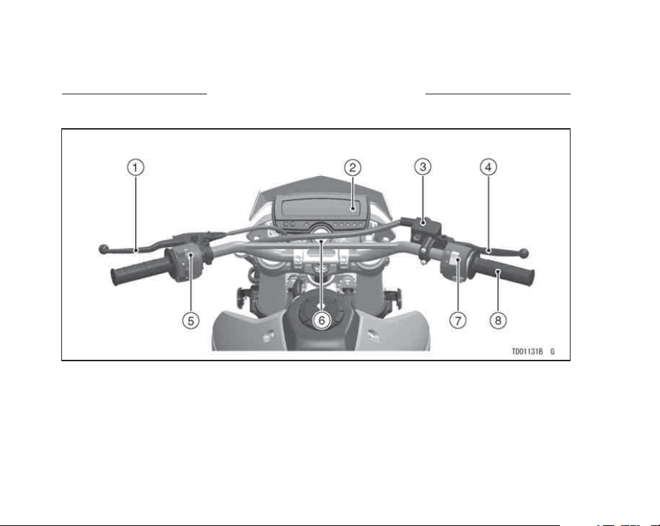
LOCATION OF PARTS
1. Clutch Lever
2. Meter Instruments
3. Brake Fluid Reservoir (Front)
4. Front Brake Lever
5. Left Handlebar Switches
6. Ignition Switch/Steering Lock
7. Right Handlebar Switches
8. Throttle Grip
LOCATION OF PARTS 13
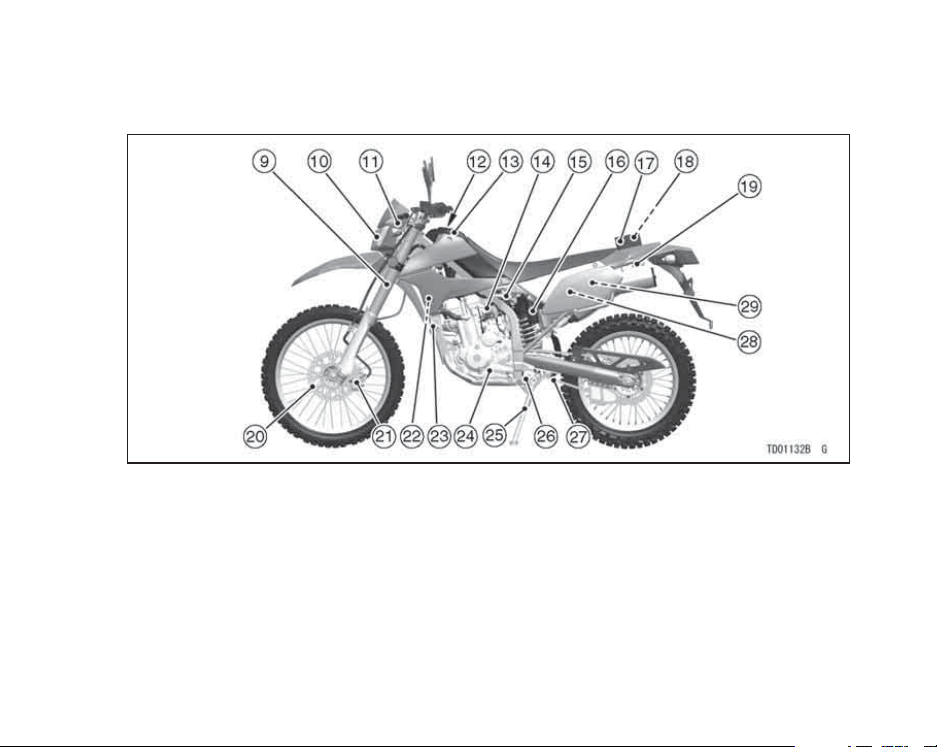
9. Front Fork
10. Headlight
11. Turn Signal Light
12. Fuel Tank Cap
13. Fuel Tank
14. Choke Knob
15. Fuel Tap
16. Rear Shock Absorber
17. Tool Kit Bag
18. Tool Kit
19. Helmet Hook
20. Brake Disc
21. Brake Caliper
22. Radiator
23. Horn
24. Shift Pedal
25. Side Stand
26. Side Stand Switch
27. Drive Chain
28. Coolant Reserve Tank
29. Battery
14 LOCATION OF PARTS
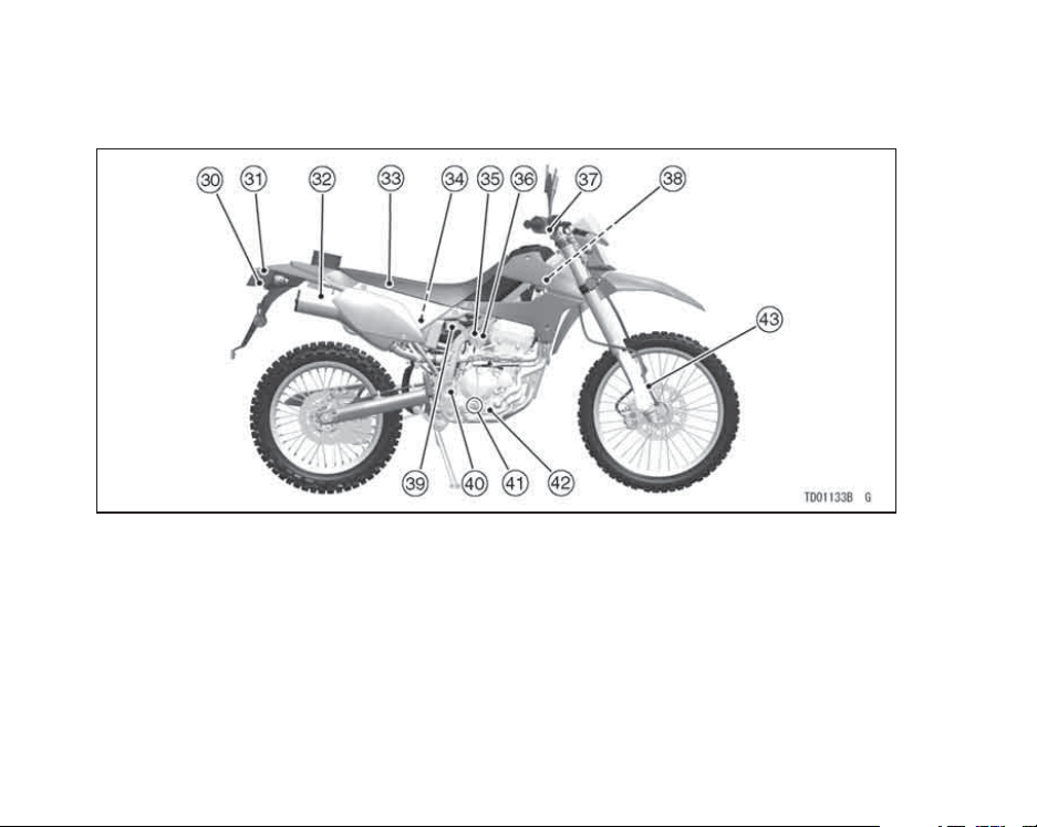
30. License Plate Light
31. Tail/Brake Light
32. Muffler
33. Seat
34. Air Cleaner Element
35. Carburetor
36. Idle Adjusting Screw
37. Front Brake Light
Switch
38. Radiator Cap
39. Brake Fluid Reservoir
(Rear)
40. Rear Brake Light
Switch
41. Oil Level Gauge
42. Rear Brake Pedal
43. Speedometer Cable
LOADING INFORMATION
LOADING INFORMATION 15
WARNING
Incorrect loading, improper installation or use of accessories,
or modification of your motorcycle may result in an unsafe riding condition. Before you ride
the motorcycle, make sure that
the motorcycle is not overloaded
and that you have followed these
instructions.
With the exception of genuine
Kawasaki Parts and Accessories,
Kawasaki has no control over the
design or application of accessories.
In some cases, improper installation
or use of accessories, or motorcycle
modification, will void the motorcycle
warranty. In selecting and using accessories, and in loading the motorcycle,
you are personally responsible for your
own safety and the safety of other persons involved.
NOTE
Kawasaki Parts and Accessories
have been specially designed for
use on Kawasaki motorcycles. We
strongly recommend that all parts
and accessories you add to your
motorcycle be genuine Kawasaki
components.
Because a motorcycle is sensitive to
changes in weight and aerodynamic
forces, you must take extreme care
in carrying cargo, passengers and/or
in the fitting of additional accessories.

16 LOADING INFORMATION
The following general guidelines have
been prepared to assist you in making
your determinations.
1. Any passenger should be thoroughly familiar with motorcycle operation. The passenger can affect
control of the motorcycle by improper positioning during cornering
and sudden movements. It is important that the passenger sit still while
the motorcycle is in motion and not
interfere with the operation of the
motorcycle. Do not carry animals
on your motorcycle.
2. You should instruct any passenger
before riding to keep his feet on the
passenger footpegs and hold on to
the operator, seat strap or grab rail.
Do not carry a passenger unless he
or she is tall enough to reach the
footpegs and footpegs are provided.
3. All baggage should be carried as
low as possible to reduce the effect
on the motorcycle center of gravity.
Baggage weight should also be distributed equally on both sides of the
motorcycle. Avoid carrying baggage
that extends beyond the rear of the
motorcycle.
4. Baggage should be securely attached. Make sure that the baggage
will not move around while you are
riding. Recheck baggage security
as often as possible (not while the
motorcycle is in motion) and adjust
as necessary.
5. Do not carry heavy or bulky items on
a luggage rack. They are designed
for light items, and overloading can
affect handling due to changes in
weight distribution and aerodynamic
forces.

LOADING INFORMATION 17
6. Do not install accessories or carry
baggage that impairs the performance of the motorcycle. Make
sure that you have not adversely
affected any lighting components,
road clearance, banking capability
(i.e., lean angle), control operation,
wheel travel, front fork movement,
or any other aspect of the motorcycle’s operation.
7. Weight attached to the handlebar or
front fork will increase the mass of
thesteeringassemblyandcanresultinanunsaferidingcondition.
8. Fairings, windshields, backrests,
and other large items have the capability of adversely affecting stability and handling of the motorcycle,
not only because of their weight, but
also due to the aerodynamic forces
acting on these surfaces while the
motorcycle is in operation. Poorly
designed or installed items can result in an unsafe riding condition.
9. This motorcycle was not intended
to be equipped with a sidecar or to
be used to tow any trailer or other
vehicle. Kawasaki does not manufacture sidecars or trailers for motorcycles and cannot predict the effects of such accessories on handling or stability, but can only warn
thattheeffectscanbeadverseand
that Kawasaki cannot assume responsibility for the results of such
unintended use of the motorcycle.
Furthermore, any adverse effects on
motorcycle components caused by
the use of such accessories will not
be remedied under warranty.
Maximum Load
Weight of rider, passenger, baggage,
and accessories must not exceed 181 kg
(399 lb).
18 GENERAL INFORMATION
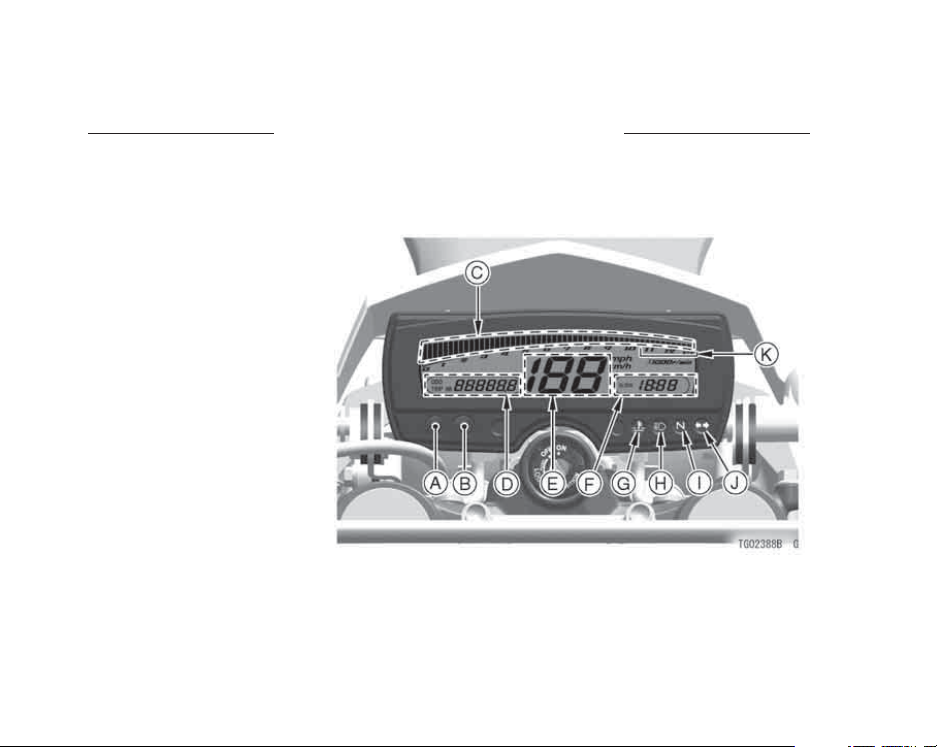
Meter Instruments
A. MODE Button
B. RESET Button
C. Tachometer Gauge
D. Odometer/Trip Meter
AB/Fuel Warning Message
E. Speedometer
F. C l o ck
G. Coolant Temperature
Warning Light
H. High Beam Indicator Light
I. Neutral Indicator Light
J. Turn Signal Indicator Light
K. Red Zone
GENERAL INFORMATION

GENERAL INFORMATION 19
Meter Instruments:
The meter displays all segments for
a few seconds when the ignition key is
turned to “ON”. The tachometer momentarily goes from the minimum to
the maximum, then goes back from the
maximum to the minimum reading to
check its operation. If any meter instruments or tachometer does not operate
or display correctly, have it checked by
an authorized Kawasaki dealer.
Tachometer Gauge:
The tachometer shows the engine
speed in revolutions per minute (r/min,
rpm). On the right side of the tachometer face is a portion called the “red
zone”. Engine r/min (rpm) in the
red zone is above maximum recommended engine speed and is also
above the range for good performance.
NOTE
This motorcycle is equipped with the
engine speed limitter to prevent the
excesive high engine speed. When
operating this limitter, the segments
of the tachometer indicate the different engine speed and stops at about
5000 r/min (rpm) for the ignition control, but this operation is not a failure.
CAUTION
Engine r/min (rpm) should not
be allowed to enter the red zone;
operation in the red zone will
overstress the engine and may
cause serious engine damage.
Speedometer :
The speedometer shows the speed
of the vehicle in digital values.
20 GENERAL INFORMATION
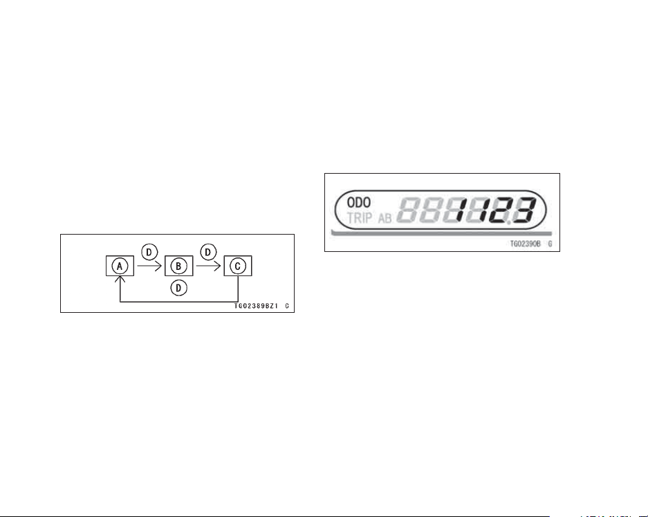
Odometer/Trip Meter AB/Fuel
Warning Message (ODO/TRIP
AB):
This meter displays the odometer,
the trip meter AB, and the fuel warning
message.
TheodometerandthetripmeterAB
can be shifted pushing the MODE button.
A. Odometer
B. Trip meter A
C. Trip meter B
D. MODE Button
NOTE
Do not shift the odometer/trip meter
while riding for safe operation.
Odometer -
The odometer shows the total distance in kilometers or miles that the vehicle has been ridden. This meter cannot be reset.
NOTE
The data is maintained even if the
battery is disconnected.
When the figures come to 999999,
they are stopped and locked.
Trip Meters A/B -
The trip meter shows the distance in
kilometers or miles traveled since it was
last reset to zero.
To r es et t h e t r ip me te r:

GENERAL INFORMATION 21
PushtheMODEbuttontodisplaythe
•
trip meter A or B.
Push the RESET button and hold it
•
in.
After two second, the figure display
•
turns to 0.0, and then starts counting
when the vehicle is operated. The
meter counts until it is next reset.
NOTE
The data is maintaine d by th e back
-up power if the ignition key is turned
off.
When the trip meter reaches 999.9
(TRIPA)or9999.9(TRIPB)while
riding, the meter resets to 0.0 and
continues counting.
When the battery is disconnected,
the meter display resets to 0.0.
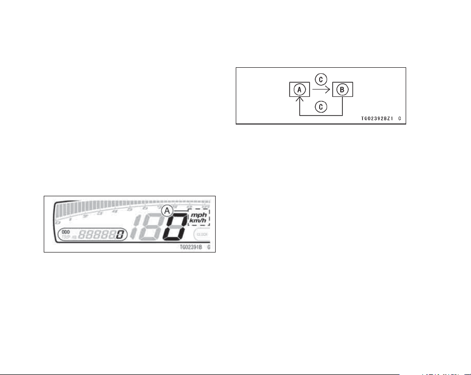
Mile/Km Display:
Mile/Km Display can alternate between English and metric modes (mph
and km/h) in the meter unit. Make sure
that km/h or mph according to local
regulations is correctly displayed before riding.
22 GENERAL INFORMATION
NOTE
Do not operate the vehicle with
the meter unit displaying in the
wrong unit (km/h or mph). Shift
the km/h·mph display in the meter
unit as follows.
Display the odometer.
•
The km/h·mph display shifts by push-
•
ing the RESET button while the
MODE button pushed in.
A. Km/h·Mph Display
The km/h/mph display shifts as fol-
•
lows.
A. Km/h
B. Mph
C.PushRESETButtonwithMODEButtonin
NOTE
The data is maintained even if the
battery is disconnected.
Clock:
To adjust hours and minutes:
Turn the ignition key to “ON”.
•
Push the RESET button for more
•
than two seconds. Both the hour and
minute displays start flashing.
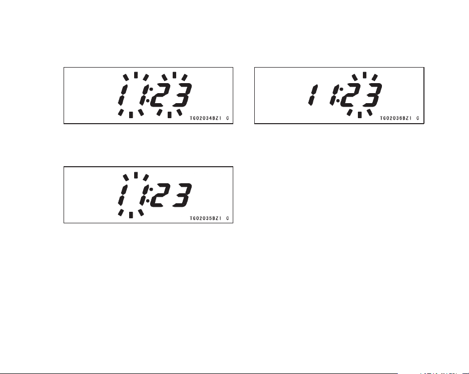
GENERAL INFORMATION 23
Push the RESET button. The hour
•
display only flashes. Push the
MODE button to advance the hours.
Push the RESET button. The hour
•
display stops flashing and the minute
display starts flashing. Push the
MODEbuttontoadvancetheminutes.
Push the RESET button. Both the
•
hour and minute displays start flashing again.
Push the MODE button. The dis-
•
playsstopflashingandtheclock
starts working.
NOTE
Pushing the MODE button momen-
tarily advances the hour or minute
step by step. Pushing and holding the button advances the hour or
minute continuously.
The clock works normally from the
back-up power while the ignition
switch is turned off.
24 GENERAL INFORMATION
When the battery is disconnected,
the clock resets to 1:00 and starts
working again whe n the battery is
connected.
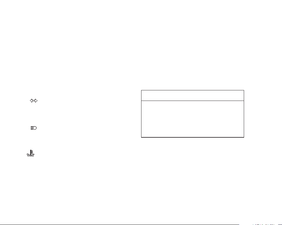
Indicator/Warning Light:
N : When the transmission is in neutral,
the neutral indicator light is lit.
: When the turn signal switch is
turned to left or right, the turn signal
indicator light flashes on and off.
: When the headlight is on high
beam, the high beam indicator light is
lit.
The coolant temperature warning
light goes on when the ignition key
is turned to “ON” and goes off soon
after ensuring that its circuit function
properly. The warning light also goes
on whenever the coolant temperature
rises too high when the motorcycle is
in operation. If it stays on, stop the
engine and check the coolant level in
the reserve tank after the engine cools
down.
CAUTION
Do not let the engine continue
running when the warning light
goes on. Prolonged engine operation will result in severe damage from overheating.
GENERAL INFORMATION 25
Key
This motorcycle has a combination
key, which is used for the ignition
switch/steering lock, helmet hook, and
fuel tank cap.
Blank keys are available at your
Kawasaki dealers. Ask your dealer to
make any additional spare keys you
may need, using your original key as a
master.
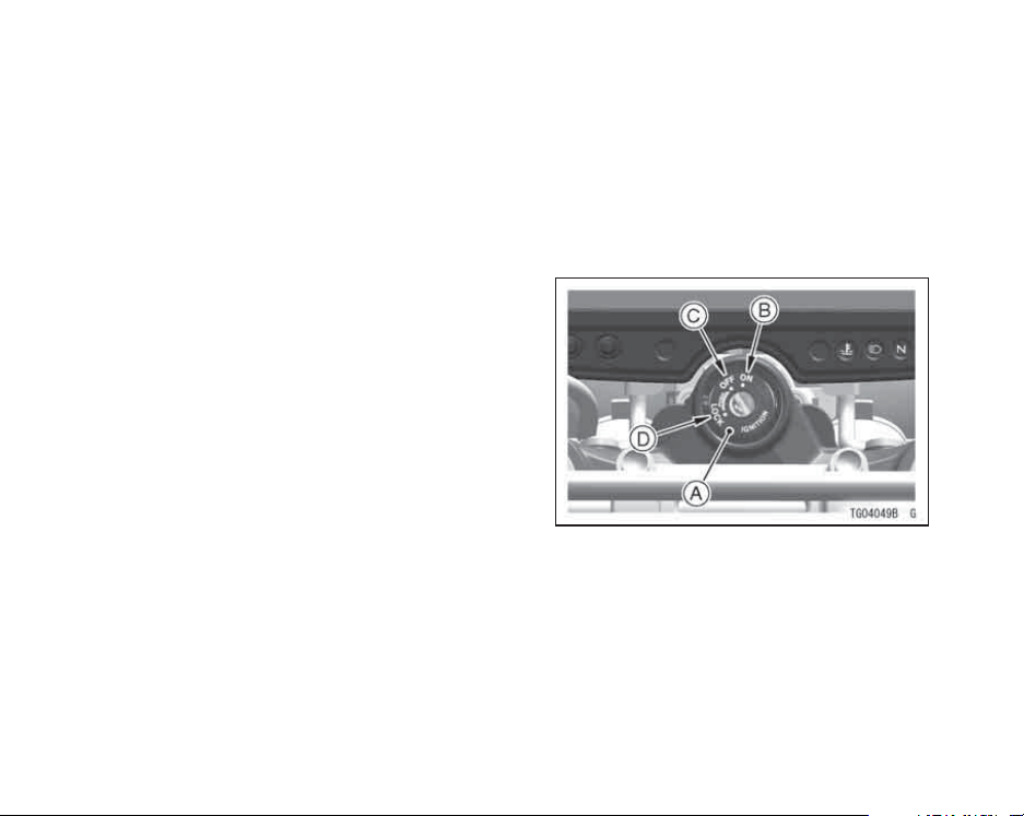
Ignition Switch/Steering Lock
This is a three-position, key-operated
switch. The key can be removed from
theswitchwhenitisintheOFFor
LOCK position.
A. Ignition Switch/Steering Lock
B. ON position
C. OFF position
D. LOCK position

26 GENERAL INFORMATION
ON
OFF
LOCK
Engine on. All electrical
equipment can be used.
Engine off. All electrical
circuits off.
Steering locked. Engine off.
All electrical circuits off.
NOTE
The headlight and taillight are on
whenever the ignition key is in the
ON position. To avoid battery discharge, always start the engine immediately after turning the ignition
key to "ON".
To lock the steering:
1. Turn the handlebar fully to the left.
2. For locking, push down the key in
the OFF position and turn it to Lock
position.
3. Pull the key out.
NOTE
If the steering is hard to lock, turn the
handlebar slightly to the left or the
right.
GENERAL INFORMATION 27
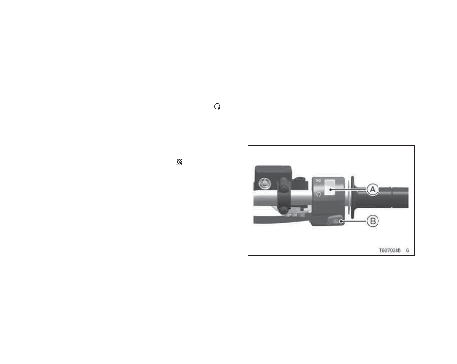
Right Handlebar Switches
Engine Stop Switch:
In addition to the ignition switch, the
engine stop switch must be in the
position for the motorcycle to operate.
Theenginestopswitchisforemergency use. If some emergency requires stopping the engine, push the
engine stop switch to the
position.
NOTE
Although the engine stop switch
stops the engine, it does not turn off
all the electrical circuits. Ordinarily,
the ignition switch should be used to
stop the engine.
Starter Button:
The starter button operates the electric starter when the transmission is in
neutral.
Refer to the Starting the Engine sectionofthe"HowtoRidetheMotorcycle"
chapter for starting instructions.
A. Engine Stop Switch
B. Starter Button
28 GENERAL INFORMATION
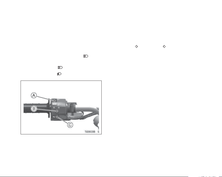
Left Handlebar Switches
Dimmer Switch:
High or low beam can be selected
with the dimmer switch. When the
headlight is on high beam
high beam indicator light is lit.
High beam.......(
Low beam.......(
A. Dimmer Switch
B. Turn Signal Switch
C. Horn Button
)
)
,the
Turn Signal Switch:
When the turn signal switch is turned
to the left
or right , the corre-
sponding turn signals flash on and off.
To stop flashing, push the switch in.
Horn Button:
When the horn button is pushed, the
horn sounds.
 Loading...