

Page 1

KLV1000
Motorcycle
Service Manual
Page 2

KLV1000
Motorcycle
Service Manual
Supplement
All rights reserved. No parts of this publication may be reproduced, stored in a retrieval system, or
transmitted in any form or by any means, electronic mechanical photocopying, recording or otherwise, without
the prior written permission of Quality Assurance Department/Consumer Products & Machinery
Company/Kawasaki Heavy Industries, Ltd., Japan. No liability can be accepted for any inaccuracies or
omissions in this publication, although every possible care has been taken to make it as complete and accurate
as possible.
The right is reserved to make changes at any time without prior notice and without incurring an obligation to
make such changes to products manufactured previously. See your Motorcycle dealer for the latest
information on product improvements incorporated after this publication.
All information contained in this publication is based on the latest product information available at the time of
publication. Illustrations and photographs in this publication are intended for reference use only and may not
depict actual model component parts.
2004 Kawasaki Heavy Industries, Ltd. First Edition (1) Feb. 12, 2004 (K)
Page 3

Page 4
Foreword
This Kawasaki Service manual supplement
information provides unique to the Kawasaki
KLV1000-A1, which is based on the Suzuki
DL1000K4. It must be used in conjunction with the
other chapters of this manual. Read both this
supplement and the base manual for complete
information on proper service procedures for the
model covered by this manual.
This manual is designed primarily for use by
trained mechanics in a properly equipped shop.
However, it contains enough detail and basic
information to make it useful to the owner who
desires to perform his own basic maintenance and
repair work. A basic knowledge of mechanics, the
proper use of tools, and workshop procedures must
be understood in order to carry out maintenance and
repair satisfactorily.
Whenever the owner has insufficient experience or
doubts his ability to do the work, all adjustments,
maintenance, and repair should be carried out only
by qualified mechanics.
In order to perform the work efficiently and to avoid
costly mistakes, read the text, thoroughly familiarize
yourself with the procedures before starting work,
and then do the work carefully in a clean area.
Whenever special tools or equipment are specified,
do not use makeshift tools or equipment. Precision
measurements can only be made if the proper
instruments are used.
For the duration of the warranty period, we
recommend that all repairs and scheduled
maintenance be performed in accordance with this
service manual. Any owner maintenance or repair
procedure not performed in accordance with this
manual may void the warranty.
To get the longest life out of your motorcycle:
zFollow the Periodic Maintenance Chart in the
Service Manual.
zBe alert for problems and non-scheduled
maintenance.
zUse proper tools and genuine Kawasaki
Motorcycle parts. Special tools, gauges, and
testers that are necessary when servicing
Kawasaki motorcycles are listed in this manual.
Genuine parts provided as spare parts are listed in
the Parts Catalog.
zFollow the procedures in this manual carefully.
Don’t take shortcuts.
zRemember to keep complete records of
maintenance and repair with dates and any new
parts installed.
How to Use This Manual
In preparing this manual, the product was divided
into its major systems, and these systems became
the manual’s chapters. All information for a particular
system from adjustment through disassembly and
inspection is located in a single chapter.
The Group Index shows you all of the product’s
systems and assists in locating their chapters. Each
chapter in turn has its own comprehensive Table of
Contents.
For example, if you want crankshaft information,
use the Group Index to locate the Engine chapter.
Then, use the Table of Contents on the first page of
the chapter to find the Crankshaft section.
Whenever you see these WARNING and
CAUTION symbols, heed their instructions! Always
follow safe operating and maintenance practices.
WARNING
This warning symbol identified special
instructions or procedures which, if not
correctly followed, could result in personal
injury, or loss of life.
CAUTION
This caution symbol identifies special
instructions or procedures which, if not strictly
observed, could result in damage to or
destruction of equipment.
This manual contains the other symbols (in
addition to WARNING and CAUTION) which will help
you distinguish different types of information.
NOTE
{This note symbol indicates points of particular
interest for more efficient and convenient
operation.
zIndicates a procedural step or work to be done.
Page 5
Symbol
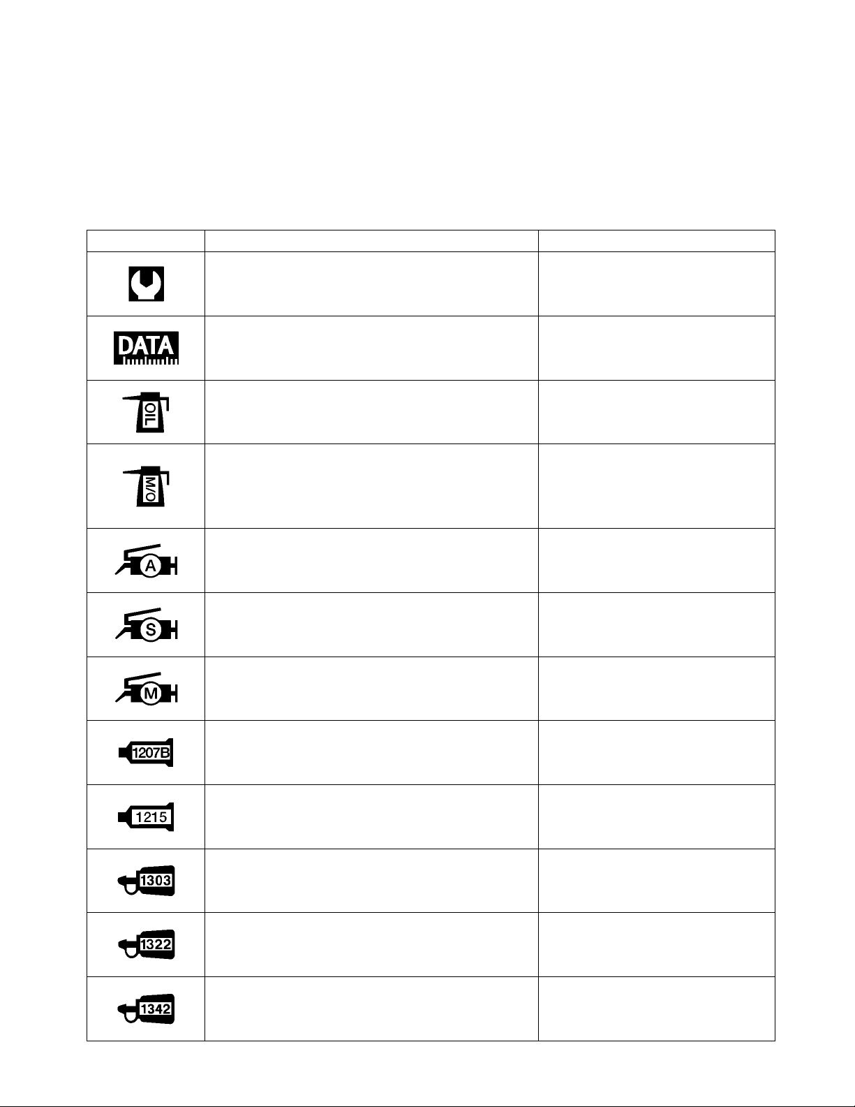
Throughout this manual are symbols indicating instructions and other information necessary for servicing.
The meaning of each symbol is included in the table below. Where applicable, comparable Kawasaki
products and their part numbers have been included.
SYMBOL SUZUKI DEFINITION KAWASAKI DEFINITION
Torque control required.
Data beside it indicates specified torque.
Indicates service data.
Apply oil. Use engine oil unless otherwise
specified.
m
m
m
Apply molybdenum oil solution.
(mixture of engine oil and SUZUKI MOLY PASTE
in a ratio of 1 : 1)
Apply SUZUKI SUPER GREASE “A”.
99000-25030 (For USA)
99000-25010 (For the other countries)
Apply SUZUKI SILICONE GRESE.
99000-25100
Apply SUZUKI MOLY PASTE.
99000-25140
Apply SUZUKI BOND “1207B”.
99104-31140 (For USA)
99000-31140 (For the other countries)
Apply SUZUKI BOND “1215”.
99000-31110 (Except USA)
Apply THREAD LOCK SUPER “1303”.
99000-32030
Apply molybdenum disulfide oil.
(a mixture of engine oil and
molybdenum disulfide grease with
a weight ratio of 1:1)
Apply grease.
Apply Silicone grease.
Apply molybdenum disulfide
grease.
Apply THREE BOND “TB1207B”.
Apply THREE BOND “TB1215”.
Apply a non-permanent locking
agent.
Apply THREAD LOCK SUPER “1322”.
99000-32110 (Except USA)
Apply THREAD LOCK “1342”.
99000-32050
Apply a non-permanent locking
agent.
Apply a non-permanent locking
agent.
Page 6
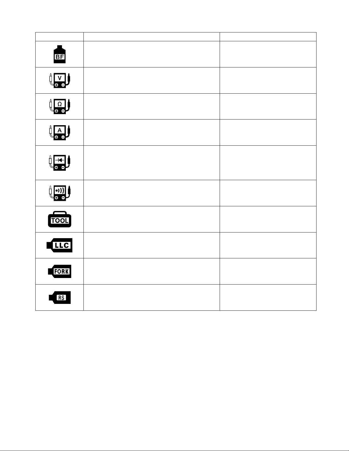
SYMBOL SUZUKI DEFINITION KAWASAKI DEFINITION
Apply or use brake fluid,
m
Measure in voltage range.
m
Measure in resistance range.
m
Measure in current range.
m
Measure in diode test range. Use a suitable commercially
available digital multi meter for a
diode tester and measure in diode
test range.
Measure in continuity test range.
m
Use special tool. Refer to the special tools in
Servicing Information chapter.
Use engine coolant.
99000-99032-11X (Except USA)
Use fork oil.
99000-99001-SS8
Use rear shock absorber oil.
99000-99001-S25
m
Front Fork Oil Viscosity
SAE 10W-20
m
Page 7

Page 8

GENERAL INFORMATION 1-1
General Information
Contents
WARNING/CAUTION/NOTE......................................................................................... Base Manual
GENERAL PRECAUTIONS .......................................................................................... 1-2
KAWASAKI LV1000-A1................................................................................................. 1-3
SERIAL NUMBER LOCATION ...................................................................................... Base Manual
FUEL, OIL, AND ENGINE COOLANT RECOMMENDATION ....................................... Base Manual
FUEL.......................................................................................................................... Base Manual
ENGINE OIL .............................................................................................................. Base Manual
BRAKE FLUID ........................................................................................................... Base Manual
FRONT FORK OIL..................................................................................................... Base Manual
ENGINE COOLANT................................................................................................... Base Manual
WATER FOR MIXING................................................................................................ Base Manual
ANTI-FREEZE/ENGINE COOLANT .......................................................................... Base Manual
LIQUID AMOUNT OF WATER/ENGINE COOLANT.................................................. Base Manual
BREAK-IN PROCEDURES........................................................................................... Base Manual
CYLINDER IDENTIFICATION....................................................................................... Base Manual
INFORMATION LABELS............................................................................................... Base Manual
SPECIFICATIONS......................................................................................................... 1-5
DIMENSIONS ............................................................................................................ 1-5
PERFORMANCE....................................................................................................... 1-5
ENGINE ..................................................................................................................... 1-5
DRIVE TRAIN ............................................................................................................ 1-6
FRAME ...................................................................................................................... 1-6
ELECTRICAL............................................................................................................. 1-6
COUNTRY AND AREA CODES.................................................................................... 1-7
Page 9

GENERAL INFORMATION 1-2
GENERAL PRECAUTIONS
CAUTION
If parts replacement is necessary, replace the parts with KAWASAKI Genuine Parts or their
equivalent.
When removing parts that are to be reused, keep them arranged in an orderly manner so that they
may be reinstalled in the proper order and orientation.
Be sure to use special tools when instructed.
Make sure that all parts used in reassembly are clean. Lubricate them when specified.
Use the specified lubricants, bands, or sealant.
When removing the battery, disconnect the negative cable first and then the positive cable.
When reconnecting the battery, connect the positive cable first and then the negative cable, and
replace the terminal cover on the positive terminal.
When performing service to electrical parts, if the service procedures not require use of battery
power, disconnect the negative cable the battery.
When tightening the cylinder head and case bolts and nuts tighten the larger sizes first.
Always tighten the bolts and nuts from the inside working out, in a crisscross manner.
Whenever you remove oil seals, gaskets, packing, O-rings, locking washers, self-locking nuts, cotter
pins, circlips, and certain other parts as specified, be sure to replace them with new ones. Also,
before installing these new parts, be sure to remove any left over material from the mating surfaces.
Never reuse a circlip. When installing a new circlip, take care not to expand the end gap larger than
required to slip the circlip over the shaft. After installing a circlip, always ensure that it is completely
seated in its groove and securely fitted.
Use a torque wrench to tighten fasteners to the specified torque. Wipe off grease and oil if a thread is
smeared with them.
After reassembling, check parts for tightness and proper operation.
To protect the environment, do not unlawfully dispose of used motor oil and all other fluids: batteries
and tires.
To protect the Earth’s natural resources, properly dispose of used motorcycle and parts.
Page 10
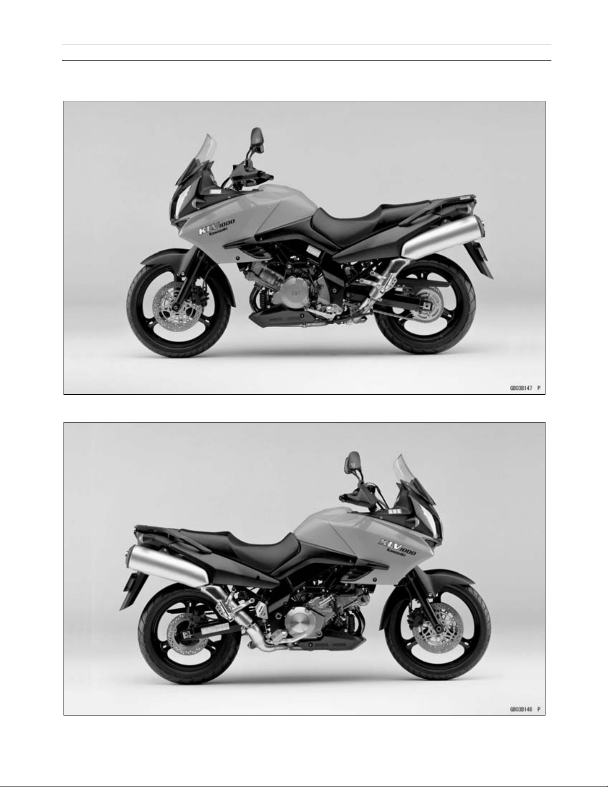
Kawasaki LV1000-A1
GENERAL INFORMATION 1-3
Page 11

GENERAL INFORMATION 1-4
SPECIFICATIONS
Items LV1000-A1
Dimensions:
Overall length 2 295 mm (90.4 in.)
Overall width 910 mm (35.8 in.)
Overall height 1 395 mm (54.9 in.)
Wheelbase 1 535 mm (60.4 in.)
Road clearance 165 mm (6.5 in.)
Seat height 840 mm (33.1 in.)
Dry mass 208 kg (458 lbs)
Fuel tank capacity 22 L (5.81 US gal)
Performance:
Minimum turning radius 2.7 m (106.3 ft.)
Engine:
Type 4-stroke, DOHC, V2-cylinder
Cooling system Liquid-cooled
Bore and stroke
Displacement 996 mL (60.8 cu in.)
Compression ratio 11.3
Carburetion system FI (Fuel Injection)
Starting system Electric starter
Ignition system Electronic ignition (transistorized)
Ignition timing
Spark plugs NGK CR8EK or ND U24ETR
Lubrication system Forced lubrication (wet sump with cooler)
Engine oil:
Type API SF or SG
Viscosity SAE10W-40
Capacity 3.3 L (3.5 US qt)
Drive Train:
Primary reduction system:
Type Gear
Reduction ratio 1.838 (57/31)
Clutch type Wet multi disc
Transmission:
Type 6-speed, constant mesh, return shift
Gear ratios: 1st 3.000 (36/12)
2nd 1.933 (29/15)
3rd 1.500 (27/18)
4th 1.227 (27/22)
5th 1.086 (25/23)
6th 0.913 (21/23)
98.0 u 66.0 mm (3.858 u 2.598 in.)
4q BTDC @ 1 200 r/min (rpm)
Page 12

GENERAL INFORMATION 1-5
Items LV1000-A1
Final drive system:
Type Chain drive
Reduction ratio 2.411 (41/17)
Overall drive ratio 4.045 @Top gear
Frame:
Type Tubular, diamond
Caster (rake angel)
Trail 111 mm (4.4 in.)
Front tire:
Type Tubeless
Size 110/80 R19 M/C 59H
Rear tire:
Type Tubeless
Size 150/70 R17 M/C 69H
Front suspension:
Type Telescopic fork
Wheel travel 160 mm (6.3 in.)
Rear suspension:
Type Swingarm
Wheel travel 159 mm (6.3 in.)
Brake type:
Front Dual discs
Rear Single disc
Electrical Equipment:
Battery 12 V 10 Ah
Headlight
Tail/brake light
Alternator:
Type Three-phase AC
26q 30c
12 V 60/55W u 2 (H4 u 2)
12 V 21/5W u 2
Specifications are subject to change without notice, and may not apply to every country.
Page 13

GENERAL INFORMATION 1-6
COUNTRY AND AREA CODES
The following codes stand for the applicable countries and area.
CODE COUNTRY OR AREA
E-02 U.K.
E-03 U.S.A. (Except for California)
E-19 EU
E-24 Australia
E-28 Canada
E-33 California (U.S.A.)
Page 14

PERIODIC MAINTENANCE 2-1
Periodic Maintenance
Contents
PERIODIC MAINTENANCE SCHEDULE .................................................................... 2-2
PERIODIC MAINTENANCE CHART........................................................................ 2-2
VALVE CLEARANCE ADJUSTMENT CHART ......................................................... 2-3
MAINTENANCE AND TUNE-UP PROCEDURES ....................................................... Base Manual
AIR CLEANER.......................................................................................................... Base Manual
SPARK PLUG ........................................................................................................... Base Manual
TAPPET CLEARANCE ............................................................................................. Base Manual
FUEL HOSE.............................................................................................................. Base Manual
ENGINE OIL AND OIL FILTER ................................................................................. Base Manual
ENGINE IDLE SPEED.............................................................................................. Base Manual
THROTTLE CABLE PLAY ........................................................................................ Base Manual
THROTTLE VALVE SYNCHRONIZATION ............................................................... Base Manual
CLUTCH ................................................................................................................... Base Manual
COOLING SYSTEM ................................................................................................. Base Manual
DRIVE CHAIN........................................................................................................... Base Manual
BRAKES ................................................................................................................... Base Manual
TIRE.......................................................................................................................... Base Manual
STEERING ............................................................................................................... Base Manual
FRONT FORK .......................................................................................................... Base Manual
REAR SUSPENSION ............................................................................................... Base Manual
EXHAUST PIPE BOLT.............................................................................................. Base Manual
CHASSIS BOLT AND NUT ....................................................................................... Base Manual
COMPRESSION PRESSURE CHECK ........................................................................ Base Manual
COMPRESSION TEST PROCEDURE..................................................................... Base Manual
OIL PRESSURE CHECK ............................................................................................. Base Manual
OIL PRESSURE TEST PROCEDURE ..................................................................... Base Manual
Page 15
PERIODIC MAINTENANCE 2-2
PERIODIC MAINTENANCE SCHEDULE
The chart below lists the recommended intervals for all the required periodic service work necessary to
keep the motorcycle operating at peak performance and economy. Maintenance intervals are expressed
in terms of hours.
NOTE
{More frequent servicing may be performed on motorcycles that are use under severe conditions.
Periodic Maintenance chart
Interval
km 1 000 6 000 12 000 18 000 24 000
miles 600 4 000 7 500 11 000 15 000
Item
Air cleaner element — I I R I
Exhaust pipe bolts and muffler bolts T — T — T
Valve clearance — — — — I
Spark plugs — I R I R
Engine oil R R R R R
Engine oil filter R — — R —
Idle speed I I I I I
Throttle cable play I I I I I
Evaporative emission control system (E-33 only)
PAIR(air supply)system — — I — I
Engine coolant Replace every 2 years.
Radiator hose — I I I I
Brakes I I I I I
Tires — I I I I
Steering I — I — I
Front fork — — I — I
Rear suspension — — I — I
Chassis bolts and nuts T T T T T
months 1 6 12 18 24
— I I I I Fuel hose
Replace every 4 years
— I — I Throttle valve synchronization I (E-33 only)
— — I — I
Replace vapor hose every 4 years
— I I I I Clutch hose
Replace every 4 years
— I I I I Clutch fluid
Replace every 2 years
I I I I I Drive chain
Clean and lublicate every 1 000 km (600 miles)
— I I I I Brake hose
Replace every 4 years
— I I I I Brake fluid
Replace every 2 years
I=Inspect and clean, adjust, replace or lubricate as necessary
R=Replace
T=Tighten
C=Clean
Page 16
PERIODIC MAINTENANCE 2-3
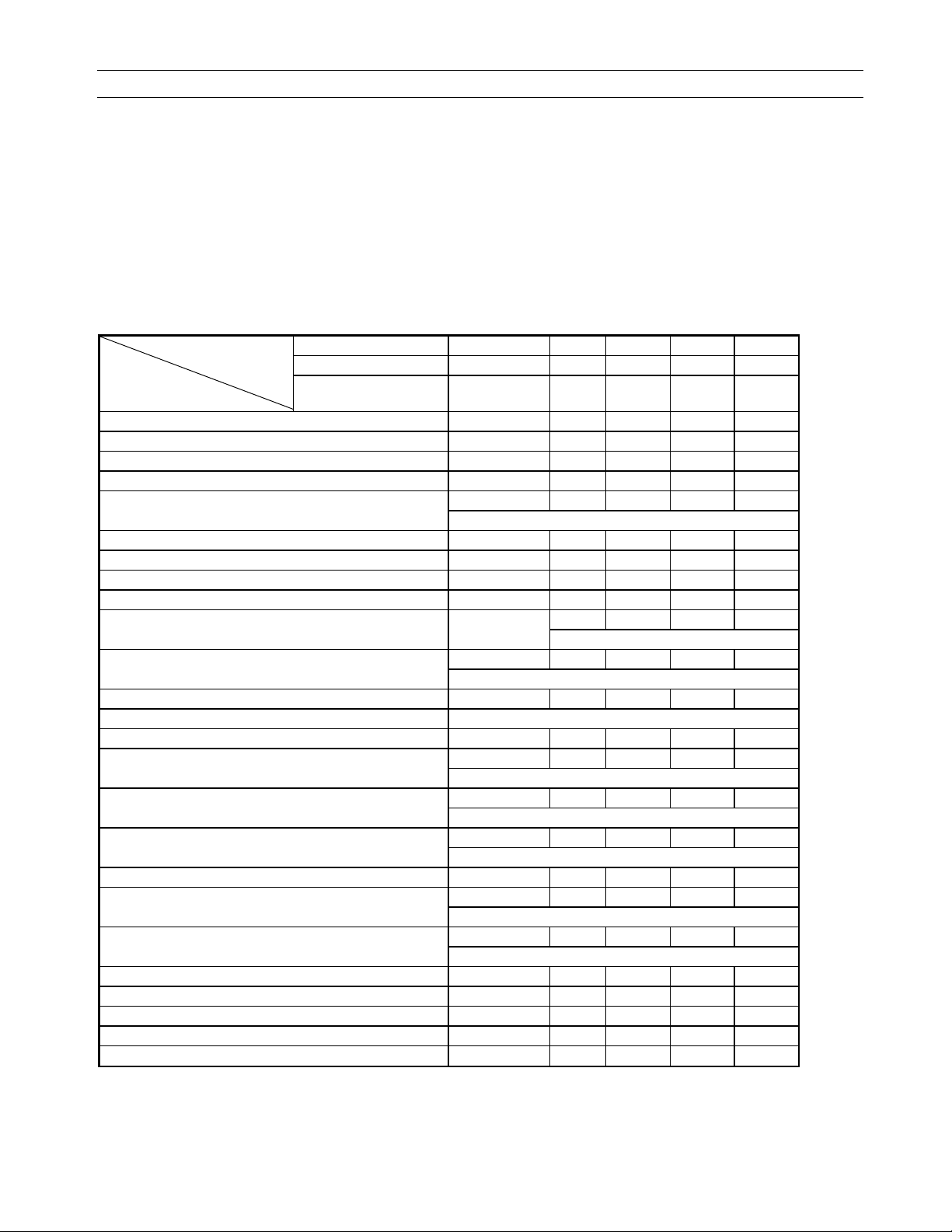
VALVE CLEARANCE ADJUSTMENT CHART INLET VALVE
INLET
㪜㫏㪸㫄㫇㫃㪼㩷
PRESENT SHIM
Part No. (92180)
MARK and
THICKNESS (mm)
0.00 ~ 0.04 2.30 2.35 2.40 2.45 2.50 2.55 2.60 2.65 2.70 2.75 2.80 2.85 2.90 2.95 3.00 3.05 3.10 3.15 3.20 3.25 3.30 3.35 3.40
0.05 ~ 0.09 2.30 2.35 2.40 2.45 2.50 2.55 2.60 2.65 2.70 2.75 2.80 2.85 2.90 2.95 3.00 3.05 3.10 3.15 3.20 3.25 3.30 3.35 3.40 3.45
0.10 ~ 0.20 SPECIFIED CLEARANCE/NO CHANGE REQUIRED
0.21 ~ 0.25 2.40 2.45 2.50 2.55 2.60 2.65 2.70 2.75 2.80 2.85 2.90 2.95 3.00 3.05 3.10 3.15 3.20 3.25 3.30 3.35 3.40 3.45 3.50 3.50
㸣Example㩷
0.26 ~ 0.30 2.45 2.50 2.55 2.60 2.65 2.70 2.75 2.80 2.85 2.90 2.95 3.00 3.05 3.10 3.15 3.20 3.25 3.30 3.35 3.40 3.45 3.50 3.50
0.31 ~ 0.35 2.50 2.55 2.60 2.65 2.70 2.75 2.80 2.85 2.90 2.95 3.00 3.05 3.10 3.15 3.20 3.25 3.30 3.35 3.40 3.45 3.50 3.50
0.36 ~ 0.40 2.55 2.60 2.65 2.70 2.75 2.80 2.85 2.90 2.95 3.00 3.05 3.10 3.15 3.20 3.25 3.30 3.35 3.40 3.45 3.50 3.50
0.41 ~ 0.45 2.60 2.65 2.70 2.75 2.80 2.85 2.90 2.95 3.00 3.05 3.10 3.15 3.20 3.25 3.30 3.35 3.40 3.45 3.50 3.50
0.46 ~ 0.50 2.65 2.70 2.75 2.80 2.85 2.90 2.95 3.00 3.05 3.10 3.15 3.20 3.25 3.30 3.35 3.40 3.45 3.50 3.50
0.51 ~ 0.55 2.70 2.75 2.80 2.85 2.90 2.95 3.00 3.05 3.10 3.15 3.20 3.25 3.30 3.35 3.40 3.45 3.50 3.50
0.56 ~ 0.60 2.75 2.80 2.85 2.90 2.95 3.00 3.05 3.10 3.15 3.20 3.25 3.30 3.35 3.40 3.45 3.50 3.50
0.61 ~ 0.65 2.80 2.85 2.90 2.95 3.00 3.05 3.10 3.15 3.20 3.25 3.30 3.35 3.40 3.45 3.50 3.50
0.66 ~ 0.70 2.85 2.90 2.95 3.00 3.05 3.10 3.15 3.20 3.25 3.30 3.35 3.40 3.45 3.50 3.50
0.71 ~ 0.75 2.90 2.95 3.00 3.05 3.10 3.15 3.20 3.25 3.30 3.35 3.40 3.45 3.50 3.50
0.76 ~ 0.80 2.95 3.00 3.05 3.10 3.15 3.20 3.25 3.30 3.35 3.40 3.45 3.50 3.50
0.81 ~ 0.85 3.00 3.05 3.10 3.15 3.20 3.25 3.30 3.35 3.40 3.45 3.50 3.50
0.86 ~ 0.90 3.05 3.10 3.15 3.20 3.25 3.30 3.35 3.40 3.45 3.50 3.50
0.91 ~ 0.95 3.10 3.15 3.20 3.25 3.30 3.35 3.40 3.45 3.50 3.50
0.96 ~ 1.00 3.15 3.20 3.25 3.30 3.35 3.40 3.45 3.50 3.50
1.01 ~ 1.05 3.20 3.25 3.30 3.35 3.40 3.45 3.50 3.50
1.06 ~ 1.10 3.25 3.30 3.35 3.40 3.45 3.50 3.50
1.11 ~ 1.15 3.30 3.35 3.40 3.45 3.50 3.50 INSTALL THE SHIM OF THIS THICKNESS (mm)
VALVE CLEARANCE MEASUREMENT (mm)
1.16 ~ 1.20 3.35 3.40 3.45 3.50 3.50
1.21 ~ 1.25 3.40 3.45 3.50 3.50
1.26 ~ 1.30 3.45 3.50 3.50
1.31 ~ 1.35 3.50 3.50
1.36 ~ 1.40 3.50
S018 S019 S020 S021 S022 S023 S024 S025 S026 S027 S028 S029 S030 S031 S032 S033 S034 S035 S036 S037 S038 S039 S040 S041 S042
2.30 2.35 2.40 2.45 2.50 2.55 2.60 2.65 2.70 2.75 2.80 2.85 2.90 2.95 3.00 3.05 3.10 3.15 3.20 3.25 3.30 3.35 3.40 3.45 3.50
㩷㸣㩷
1. Measure the clearance (when engine is cold.)
2. Check present shim size.
3. Match clearance in vertical column with present shim size in horizontal column.
4. Install the shim specified where the lines intersect. This shim will give the proper clearance.
Example : Present shim is 2.70 mm.
Measured clearance is 0.23 mm.
Replace 2.70 mm shim with 2.80 mm shim.
5. Remeasure the valve clearance and readjust if necessary.
Page 17
PERIODIC MAINTENANCE 2-4
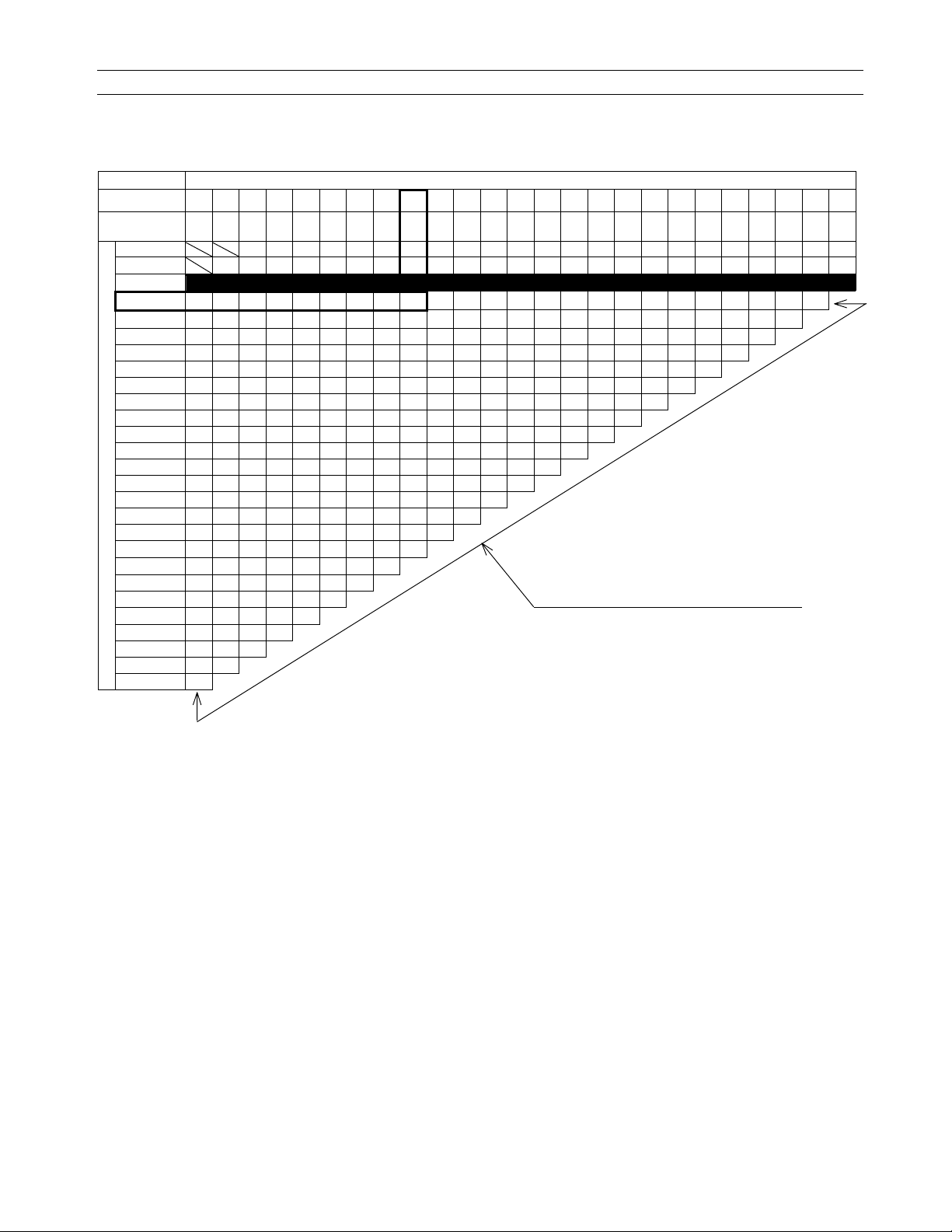
VALVE CLEARANCE ADJUSTMENT CHART EXHAUST VALVE
EXHAUST
㩷㸣㩷
PRESENT SHIM
Part No. (92180)
MARK and
THICKNESS (mm)
0.00 ~ 0.04 2.30 2.35 2.40 2.45 2.50 2.55 2.60 2.65 2.70 2.75 2.80 2.85 2.90 2.95 3.00 3.05 3.10 3.15 3.20 3.25 3.30
0.05 ~ 0.09 2.30 2.35 2.40 2.45 2.50 2.55 2.60 2.65 2.70 2.75 2.80 2.85 2.90 2.95 3.00 3.05 3.10 3.15 3.20 3.25 3.30 3.35
0.10 ~ 0.14 2.30 2.35 2.40 2.45 2.50 2.55 2.60 2.65 2.70 2.75 2.80 2.85 2.90 2.95 3.00 3.05 3.10 3.15 3.20 3.25 3.30 3.35 3.40
0.15 ~ 0.19 2.30 2.35 2.40 2.45 2.50 2.55 2.60 2.65 2.70 2.75 2.80 2.85 2.90 2.95 3.00 3.05 3.10 3.15 3.20 3.25 3.30 3.35 3.40 3.45
0.20 ~ 0.30 SPECIFIED CLEARANCE/NO CHANGE REQUIRED
0.31 ~ 0.35 2.40 2.45 2.50 2.55 2.60 2.65 2.70 2.75 2.80 2.85 2.90 2.95 3.00 3.05 3.10 3.15 3.20 3.25 3.30 3.35 3.40 3.45 3.50 3.50
0.36 ~ 0.40 2.45 2.50 2.55 2.60 2.65 2.70 2.75 2.80 2.85 2.90 2.95 3.00 3.05 3.10 3.15 3.20 3.25 3.30 3.35 3.40 3.45 3.50 3.50
㸣Example㩷
0.41 ~ 0.45 2.50 2.55 2.60 2.65 2.70 2.75 2.80 2.85 2.90 2.95 3.00 3.05 3.10 3.15 3.20 3.25 3.30 3.35 3.40 3.45 3.50 3.50
0.46 ~ 0.50 2.55 2.60 2.65 2.70 2.75 2.80 2.85 2.90 2.95 3.00 3.05 3.10 3.15 3.20 3.25 3.30 3.35 3.40 3.45 3.50 3.50
0.51 ~ 0.55 2.60 2.65 2.70 2.75 2.80 2.85 2.90 2.95 3.00 3.05 3.10 3.15 3.20 3.25 3.30 3.35 3.40 3.45 3.50 3.50
0.56 ~ 0.60 2.65 2.70 2.75 2.80 2.85 2.90 2.95 3.00 3.05 3.10 3.15 3.20 3.25 3.30 3.35 3.40 3.45 3.50 3.50
0.61 ~ 0.65 2.70 2.75 2.80 2.85 2.90 2.95 3.00 3.05 3.10 3.15 3.20 3.25 3.30 3.35 3.40 3.45 3.50 3.50
0.66 ~ 0.70 2.75 2.80 2.85 2.90 2.95 3.00 3.05 3.10 3.15 3.20 3.25 3.30 3.35 3.40 3.45 3.50 3.50
0.71 ~ 0.75 2.80 2.85 2.90 2.95 3.00 3.05 3.10 3.15 3.20 3.25 3.30 3.35 3.40 3.45 3.50 3.50
0.76 ~ 0.80 2.85 2.90 2.95 3.00 3.05 3.10 3.15 3.20 3.25 3.30 3.35 3.40 3.45 3.50 3.50
0.81 ~ 0.85 2.90 2.95 3.00 3.05 3.10 3.15 3.20 3.25 3.30 3.35 3.40 3.45 3.50 3.50
0.86 ~ 0.90 2.95 3.00 3.05 3.10 3.15 3.20 3.25 3.30 3.35 3.40 3.45 3.50 3.50
0.91 ~ 0.95 3.00 3.05 3.10 3.15 3.20 3.25 3.30 3.35 3.40 3.45 3.50 3.50
0.96 ~ 1.00 3.05 3.10 3.15 3.20 3.25 3.30 3.35 3.40 3.45 3.50 3.50
1.01 ~ 1.05 3.10 3.15 3.20 3.25 3.30 3.35 3.40 3.45 3.50 3.50
1.06 ~ 1.10 3.15 3.20 3.25 3.30 3.35 3.40 3.45 3.50 3.50
1.11 ~ 1.15 3.20 3.25 3.30 3.35 3.40 3.45 3.50 3.50
1.16 ~ 1.20 3.25 3.30 3.35 3.40 3.45 3.50 3.50 INSTALL THE SHIM OF THIS THICKNESS (mm)
1.21 ~ 1.25 3.30 3.35 3.40 3.45 3.50 3.50
VALVE CLEARANCE MEASUREMENT (mm)
1.26 ~ 1.30 3.35 3.40 3.45 3.50 3.50
1.31 ~ 1.35 3.40 3.45 3.50 3.50
1.36 ~ 1.40 3.45 3.50 3.50
1.41 ~ 1.45 3.50 3.50
1.46 ~ 1.50 3.50
S018 S019 S020 S021 S022 S023 S024 S025 S026 S027 S028 S029 S030 S031 S032 S033 S034 S035 S036 S037 S038 S039 S040 S041 S042
2.30 2.35 2.40 2.45 2.50 2.55 2.60 2.65 2.70 2.75 2.80 2.85 2.90 2.95 3.00 3.05 3.10 3.15 3.20 3.25 3.30 3.35 3.40 3.45 3.50
㩷
㪜㫏㪸㫄㫇㫃㪼㩷
1. Measure the clearance (when engine is cold.)
2. Check present shim size.
3. Match clearance in vertical column with present shim size in horizontal column.
4. Install the shim specified where the lines intersect. This shim will give the proper clearance.
Example : Present shim is 2.90 mm.
Measured clearance is 0.38 mm.
Replace 2.90 mm shim with 3.05 mm shim.
5. Remeasure the valve clearance and readjust if necessary.
Page 18

ENGINE 3-1
Engine
Contents
ENGINE COMPONENTS REMOVABLE WITH ENGINE IN PLACE ...........................Base Manual
ENGINE LEFT SIDE.................................................................................................Base Manual
ENGINE RIGHT SIDE...............................................................................................Base Manual
ENGINE CENTER ....................................................................................................Base Manual
ENGINE REMOVAL AND REMOUNTING ...................................................................Base Manual
ENGINE REMOVAL..................................................................................................Base Manual
ENGINE REMOUNTING ..........................................................................................Base Manual
ENGINE DISASSEMBLY .............................................................................................Base Manual
ENGINE COMPONENTS INSPECTION AND SERVICE.............................................Base Manual
CYLINDER HEAD.....................................................................................................Base Manual
CAMSHAFT/AUTOMATIC DECOMPRESSION ASSEMBLY ...................................Base Manual
CYLINDER................................................................................................................Base Manual
PISTON AND PISTON RING....................................................................................Base Manual
CONROD..................................................................................................................Base Manual
CRANKSHAFT .........................................................................................................Base Manual
STARTER CLUTCH..................................................................................................Base Manual
STARTER TORQUE LIMITER ..................................................................................Base Manual
OIL PUMP.................................................................................................................Base Manual
CLUTCH ...................................................................................................................Base Manual
GEARSHIFT FORK AND GEAR...............................................................................Base Manual
TRANSMISSION ......................................................................................................Base Manual
BEARINGS ...............................................................................................................Base Manual
OIL SEALS ...............................................................................................................Base Manual
ENGINE REASSEMBLY ..............................................................................................Base Manual
CRANKSHAFT .........................................................................................................Base Manual
GEARSHIFT CAM AND FORK.................................................................................Base Manual
CRANKCASE ...........................................................................................................Base Manual
STARTER CLUTCH AND GENERATOR ROTOR....................................................Base Manual
BALANCER SHAFT..................................................................................................Base Manual
PRIMARY DRIVE GEAR ..........................................................................................Base Manual
GEARSHIFT CAM DRIVEN GEAR...........................................................................Base Manual
GEARSHIFT SHAFT.................................................................................................Base Manual
OIL PUMP.................................................................................................................Base Manual
CAM CHAIN..............................................................................................................Base Manual
CLUTCH ...................................................................................................................Base Manual
RIGHT CRANKCASE COVER..................................................................................Base Manual
CLUTCH COVER .....................................................................................................Base Manual
GENERATOR ROTOR COVER................................................................................Base Manual
STARTER DRIVE GEAR COVER ............................................................................Base Manual
PISTON RING...........................................................................................................Base Manual
PISTON AND CYLINDER.........................................................................................Base Manual
CYLINDER HEAD.....................................................................................................Base Manual
CAMSHAFT/AUTOMATIC DECOMPRESSION ASSEMBLY ...................................Base Manual
CYLINDER HEAD COVER.......................................................................................Base Manual
CAM CHAIN TENSION ADJUSTER.........................................................................Base Manual
Page 19

ENGINE 3-2
Page 20

FI SYSTEM 4-1
FI System
Contents
PRECAUTIONS IN SERVICING ................................................................................... Base Manual
CONNECTOR/COUPLER ......................................................................................... Base Manual
FUSE ......................................................................................................................... Base Manual
ECM/VARIOUS SENSORS ....................................................................................... Base Manual
ELECTRICAL CIRCUIT INSPECTION PROCEDURE .............................................. Base Manual
FI SYSTEM TECHNICAL FEATURES .......................................................................... Base Manual
INJECTION TIME (INJECTION VOLUME)................................................................ Base Manual
COMPENSATION OF INJECTION TIME (VOLUME)................................................ Base Manual
INJECTION STOP CONTROL................................................................................... Base Manual
FUEL DELIVERY SYSTEM ....................................................................................... Base Manual
FUEL PUMP .............................................................................................................. Base Manual
FUEL PRESSURE REGULATOR.............................................................................. Base Manual
FUEL INJECTOR....................................................................................................... Base Manual
FUEL PUMP CONTROL SYSTEM ............................................................................ Base Manual
ECM (FI CONTROL UNIT) ........................................................................................ Base Manual
INJECTION TIMING .................................................................................................. Base Manual
SENSORS ................................................................................................................. Base Manual
FI SYSTEM PARTS LOCATION ................................................................................... Base Manual
FI SYSTEM WIRING DIAGRAM ................................................................................... Base Manual
SELF-DIAGNOSIS FUNCTION..................................................................................... Base Manual
USER MODE ........................................................................................................... Base Manual
DEALER MODE......................................................................................................... Base Manual
TPS ADJUSTMENT................................................................................................... Base Manual
FAIL-SAFE FUNCTION................................................................................................. Base Manual
FI SYSTEM TROUBLESHOOTING .............................................................................. Base Manual
CUSTOMER COMPLAINT ANALYSIS ...................................................................... Base Manual
SELF-DIAGNOSTIC PROCEDURES........................................................................ Base Manual
SELF-DIAGNOSIS RESET PROCEDURE................................................................ Base Manual
MALFUNCTION CODE AND DEFECTIVE CONDITION........................................... Base Manual
“C11” CMP SENSOR CIRCUIT MALFUNCTION....................................................... Base Manual
“C12” CKP SENSOR CIRCUIT MALFUNCTION ....................................................... Base Manual
“C13” IAP SENSOR CIRCUIT MALFUNCTION......................................................... Base Manual
“C14” TP SENSOR CIRCUIT MALFUNCTION.......................................................... Base Manual
“C15” ECT SENSOR CIRCUIT MALFUNCTION....................................................... Base Manual
“C21” IAT SENSOR CIRCUIT MALFUNCTION......................................................... Base Manual
“C22” AP SENSOR CIRCUIT MALFUNCTION.......................................................... Base Manual
“C23” TO SENSOR CIRCUIT MALFUNCTION ......................................................... Base Manual
“C24” or “25” IGNITION SYSTEM MALFUNCTION................................................... Base Manual
“C28” STV ACTUATOR CIRCUIT MALFUNCTION ................................................... Base Manual
“C29” STP SENSOR CIRCUIT MALFUNCTION ....................................................... Base Manual
“C31” GEAR POSITION (GP) SWITCH CIRCUIT MALFUNCTION .......................... Base Manual
“C32” or “C33” FUEL INJECTION MALFUNCTION................................................... Base Manual
“C41” FP RELAY CIRCUIT MALFUNCTION ............................................................. Base Manual
Page 21

FI SYSTEM 4-2
“C42” IG SWITCH CIRCUIT MALFUNCTION ........................................................... Base Manual
“C44” HO
FUEL SYSTEM ............................................................................................................. Base Manual
FUEL TANK LIFT-UP ................................................................................................. Base Manual
FUEL TANK REMOVAL ............................................................................................. Base Manual
FUEL TANK INSTALLATION ..................................................................................... Base Manual
FUEL PRESSURE INSPECTION.............................................................................. Base Manual
FUEL PUMP INSPECTION ....................................................................................... Base Manual
FUEL PUMP RELAY INSPECTION ........................................................................... Base Manual
FUEL PUMP AND FUEL FILTER REMOVAL ............................................................ Base Manual
FUEL MESH FILTER INSPECTION AND CLEANING .............................................. Base Manual
FUEL PUMP AND FUEL MESH FILTER INSTALLATION ......................................... Base Manual
THROTTLE BODY AND STV ACTUATOR ................................................................... Base Manual
CONSTRUCTION...................................................................................................... Base Manual
THROTTLE BODY REMOVAL .................................................................................. Base Manual
THROTTLE BODY DISASSEMBLY........................................................................... Base Manual
THROTTLE BODY CLEANING ................................................................................. Base Manual
INSPECTION............................................................................................................. Base Manual
THROTTLE BODY REASSEMBLY............................................................................ Base Manual
STP SENSOR ADJUSTMENT................................................................................... Base Manual
THROTTLE BODY INSTALLATION........................................................................... Base Manual
TP SENSOR ADJUSTMENT ..................................................................................... Base Manual
FUEL INJECTOR INSPECTION................................................................................ Base Manual
FUEL INJECTOR INSTALLATION............................................................................. Base Manual
FAST IDLE INSPECTION.......................................................................................... Base Manual
FAST IDLE ADJUSTMENT ........................................................................................ Base Manual
THROTTLE VALVE SYNCHRONIZATION ................................................................ Base Manual
THROTTLE CABLE ADJUSTMENT .......................................................................... Base Manual
SENSOR ....................................................................................................................... Base Manual
IAP SENSOR INSPECTION...................................................................................... Base Manual
IAP SENSOR REMOVAL/INSTALLATION................................................................. Base Manual
TP SENSOR INSPECTION ....................................................................................... Base Manual
TP SENSOR REMOVAL/INSTALLATION.................................................................. Base Manual
STP SENSOR INSPECTION..................................................................................... Base Manual
STP SENSOR REMOVAL/INSTALLATION ............................................................... Base Manual
CKP SENSOR INSPECTION .................................................................................... Base Manual
CKP SENSOR REMOVAL/INSTALLATION ............................................................... Base Manual
CMP SENSOR INSPECTION.................................................................................... Base Manual
CMP SENSOR REMOVAL/INSTALLATION .............................................................. Base Manual
IAT SENSOR INSPECTION ...................................................................................... Base Manual
IAT SENSOR REMOVAL/INSTALLATION................................................................. Base Manual
ECT SENSOR INSPECTION..................................................................................... Base Manual
ECT SENSOR REMOVAL/INSTALLATION ............................................................... Base Manual
AP SENSOR INSPECTION....................................................................................... Base Manual
AP SENSOR REMOVAL/INSTALLATION.................................................................. Base Manual
TO SENSOR INSPECTION....................................................................................... Base Manual
TO SENSOR REMOVAL/INSTALLATION ................................................................. Base Manual
HO
SENSOR INSPECTION ..................................................................................... Base Manual
2
HO
SENSOR REMOVAL/INSTALLATION................................................................ Base Manual
2
SENSOR (HO2S) CIRCUIT MALFUNCTION ........................................... Base Manual
2
Page 22

COOLING SYSTEM 5-1
Cooling System
Contents
ENGINE COOLANT ...................................................................................................... Base Manual
COOLING CIRCUIT ...................................................................................................... Base Manual
COOLING CIRCUIT INSPECTION............................................................................ Base Manual
RADIATOR.................................................................................................................... Base Manual
REMOVAL ................................................................................................................. Base Manual
INSPECTION AND CLEANING................................................................................. Base Manual
INSTALLATION.......................................................................................................... Base Manual
RADIATOR RESERVOIR TANK.................................................................................... Base Manual
REMOVAL./INSTALLATION ...................................................................................... Base Manual
RADIATOR CAP............................................................................................................ Base Manual
INSPECTION............................................................................................................. Base Manual
WATER HOSE .............................................................................................................. Base Manual
INSPECTION............................................................................................................. Base Manual
COOLING FAN.............................................................................................................. Base Manual
REMOVAL ................................................................................................................. Base Manual
INSPECTION............................................................................................................. Base Manual
INSTALLATION.......................................................................................................... Base Manual
COOLING FAN THERMO-SWITCH.............................................................................. Base Manual
REMOVAL ................................................................................................................. Base Manual
INSPECTION............................................................................................................. Base Manual
INSTALLATION.......................................................................................................... Base Manual
ENGINE COOLANT TEMPERATURE SENSOR .......................................................... Base Manual
REMOVAL ................................................................................................................. Base Manual
INSPECTION............................................................................................................. Base Manual
INSTALLATION.......................................................................................................... Base Manual
Page 23

COOLING SYSTEM 5-2
THERMOSTAT.............................................................................................................. Base Manual
REMOVAL ................................................................................................................. Base Manual
INSPECTION............................................................................................................. Base Manual
INSTALLATION.......................................................................................................... Base Manual
WATER PUMP .............................................................................................................. Base Manual
REMOVAL AND DISASSEMBLY ............................................................................... Base Manual
INSPECTION............................................................................................................. Base Manual
REASSEMBLY AND INSTALLATION ........................................................................ Base Manual
LUBRICATION SYSTEM............................................................................................... Base Manual
OIL PRESSURE ........................................................................................................ Base Manual
OIL FILTER ................................................................................................................ Base Manual
OIL PRESSURE REGULATOR ................................................................................. Base Manual
OIL STRAINER.......................................................................................................... Base Manual
OIL JET...................................................................................................................... Base Manual
OIL PUMP.................................................................................................................. Base Manual
OIL PRESSURE SWITCH ......................................................................................... Base Manual
OIL COOLER ................................................................................................................ Base Manual
REMOVAL ................................................................................................................. Base Manual
INSPECTION AND CLEANING................................................................................. Base Manual
INSTALLATION.......................................................................................................... Base Manual
ENGINE LUBRICATION FLOW CHART....................................................................... Base Manual
ENGINE LUBRICATION CIRCUIT ................................................................................ Base Manual
Page 24

CHASSIS 6-1
Chassis
Contents
EXTERIOR PARTS.........................................................................................Base Manual
CONSTRUCTION........................................................................................ Base Manual
REMOVAL ...................................................................................................Base Manual
FRONT WHEEL .............................................................................................Base Manual
CONSTRUCTION........................................................................................ Base Manual
REMOVAL ...................................................................................................Base Manual
INSPECTION AND DISASSEMBLY ............................................................ Base Manual
REASSEMBLY AND REMOUNTING........................................................... Base Manual
FRONT FORK ................................................................................................ Base Manual
CONSTRUCTION........................................................................................ Base Manual
REMOVAL AND DISASSEMBLY................................................................. Base Manual
INSPECTION ..............................................................................................Base Manual
REASSEMBLY AND REMOUNTING........................................................... Base Manual
STEERING AND HANDLEBAR ...................................................................... Base Manual
CONSTRUCTION........................................................................................ Base Manual
REMOVAL ...................................................................................................Base Manual
INSPECTION AND DISASSEMBLY ............................................................ Base Manual
REASSEMBLY AND REMOUNTING........................................................... Base Manual
STEERING TENSION ADJUSTMENT ........................................................Base Manual
REAR WHEEL................................................................................................ Base Manual
CONSTRUCTION........................................................................................ Base Manual
REMOVAL ...................................................................................................Base Manual
INSPECTION AND DISASSEMBLY ............................................................ Base Manual
REASSEMBLY AND REMOUNTING........................................................... Base Manual
REAR SHOCK ABSORBER ...........................................................................Base Manual
CONSTRUCTION........................................................................................ Base Manual
REMOVAL ...................................................................................................Base Manual
INSPECTION ..............................................................................................Base Manual
REAR SHOCK ABSORBER DISPOSAL .....................................................Base Manual
REMOUNTING............................................................................................ Base Manual
SUSPENSION SETTING ............................................................................Base Manual
REAR SWINGARM ........................................................................................Base Manual
CONSTRUCTION........................................................................................ Base Manual
REMOVAL ...................................................................................................Base Manual
INSPECTION AND DISASSEMBLY ............................................................ Base Manual
REASSEMBLY ............................................................................................Base Manual
REMOUNTING............................................................................................ Base Manual
FINAL INSPECTION AND ADJUSTMENT ..................................................Base Manual
Page 25

CHASSIS 6-2
FRONT BRAKE ..............................................................................................Base Manual
CONSTRUCTION........................................................................................ Base Manual
BRAKE PAD REPLACEMENT .................................................................... Base Manual
BRAKE FLUID REPLACEMENT ................................................................. Base Manual
CALIPER REMOVAL AND DISASSEMBLY................................................. Base Manual
CALIPER INSPECTION .............................................................................. Base Manual
CALIPER REASSEMBLY AND REMOUNTING ..........................................Base Manual
BRAKE DISC INSPECTION........................................................................ Base Manual
MASTER CYLINDER REMOVAL AND DISASSEMBLY .............................. Base Manual
MASTER CYLINDER INSPECTION............................................................ Base Manual
MASTER CYLINDER REASSEMBLY AND REMOUNTING........................ Base Manual
REAR BRAKE ................................................................................................Base Manual
CONSTRUCTION........................................................................................ Base Manual
BRAKE PAD REPLACEMENT .................................................................... Base Manual
BRAKE FLUID REPLACEMENT ................................................................. Base Manual
CALIPER REMOVAL AND DISASSEMBLY................................................. Base Manual
CALIPER INSPECTION .............................................................................. Base Manual
BRAKE DISC INSPECTION........................................................................ Base Manual
CALIPER REASSEMBLY AND REMOUNTING ..........................................Base Manual
MASTER CYLINDER REMOVAL AND DISASSEMBLY .............................. Base Manual
MASTER CYLINDER INSPECTION............................................................ Base Manual
MASTER CYLINDER REASSEMBLY AND REMOUNTING........................ Base Manual
CLUTCH RELEASE CYLINDER AND MASTER CYLINDER .........................Base Manual
CONSTRUCTION........................................................................................ Base Manual
CLUTCH FLUID REPLACEMENT............................................................... Base Manual
CLUTCH RELEASE CYLINDER REMOVAL AND DISASSEMBLY............. Base Manual
CLUTCH RELEASE CYLINDER INSPECTION ..........................................Base Manual
CLUTCH RELEASE CYLINDER REASSEMBLY AND REMOUNTING....... Base Manual
CLUTCH MASTER CYLINDER REMOVAL AND DISASSEMBLY ..............Base Manual
CLUTCH MASTER CYLINDER INSPECTION ............................................Base Manual
CLUTCH MASTER CYLINDER REASSEMBLY AND REMOUNTING ........ Base Manual
TIRE AND WHEEL .........................................................................................Base Manual
TIRE REMOVAL.......................................................................................... Base Manual
INSPECTION ..............................................................................................Base Manual
VALVE INSTALLATION ...............................................................................Base Manual
TIRE INSTALLATION ..................................................................................Base Manual
Page 26

ELECTRICAL SYSTEM 7-1
Electrical System
Contents
CAUTIONS IN SERVICING .........................................................................................Base Manual
CONNECTORS ........................................................................................................ Base Manual
COUPLERS .............................................................................................................. Base Manual
CLAMPS ................................................................................................................... Base Manual
FUSE ........................................................................................................................ Base Manual
SEMI-CONDUCTOR EQUIPPED PARTS ................................................................ Base Manual
BATTERY.................................................................................................................. Base Manual
CONNECTING THE BATTERY ................................................................................Base Manual
WIRING PROCEDURE ............................................................................................ Base Manual
USING THE MULTI CIRCUIT TESTER .................................................................... Base Manual
LOCATION OF ELECTRICAL COMPONENTS ........................................................... Base Manual
CHARGING SYSTEM .................................................................................................. Base Manual
TROUBLESHOOTING.............................................................................................. Base Manual
INSPECTION............................................................................................................ Base Manual
STARTER SYSTEM AND SIDE-STAND/IGNITION INTERLOCK SYSTEM................ Base Manual
TROUBLESHOOTING.............................................................................................. Base Manual
STARTER MOTOR REMOVAL AND DISASSEMBLY .............................................. Base Manual
STARTER MOTOR INSPECTION ............................................................................ Base Manual
STARTER MOTOR REASSEMBLY .......................................................................... Base Manual
STARTER RELAY INSPECTION .............................................................................. Base Manual
SIDE-STAND/IGNITION INTERLOCK SYSTEM PARTS INSPECTION .................. Base Manual
IGNITION SYSTEM ..................................................................................................... Base Manual
TROUBLESHOOTING.............................................................................................. Base Manual
INSPECTION............................................................................................................ Base Manual
COMBINATION METER............................................................................................... Base Manual
REMOVAL AND DISASSEMBLY .............................................................................. Base Manual
INSPECTION............................................................................................................ Base Manual
ENGINE COOLANT TEMPERATURE METER AND INDICATOR ...........................Base Manual
LAMPS ......................................................................................................................... Base Manual
HEADLIGHT, BRAKE LIGHT/TAILLIGHT AND TURN SIGNAL LIGHT.................... Base Manual
RELAYS ....................................................................................................................... Base Manual
TURN SIGNAL/SIDE-STAND RELAY....................................................................... Base Manual
STARTER RELAY ..................................................................................................... Base Manual
FUEL PUMP RELAY ................................................................................................. Base Manual
SWITCHES............................................................................................................... Base Manual
BATTERY..................................................................................................................... Base Manual
SPECIFICATIONS .................................................................................................... Base Manual
INITIAL CHARGING ................................................................................................. Base Manual
SERVICING .............................................................................................................. Base Manual
RECHARGING OPERATION.................................................................................... Base Manual
Page 27

ELECTRICAL SYSTEM 7-2
Page 28

SERVICING INFORMATION 8-1
Servicing Information
Contents
TROUBLESHOOTING ..................................................................................................Base Manual
FI SYSTEM MALFUNCTION CODE AND DEFECTIVE CONDITION ....................... Base Manual
ENGINE .....................................................................................................................Base Manual
RADIATOR (COOLING SYSTEM) ............................................................................. Base Manual
CHASSIS ...................................................................................................................Base Manual
BRAKES..................................................................................................................... Base Manual
ELECTRICAL .............................................................................................................Base Manual
BATTERY................................................................................................................... Base Manual
WIRE HARNESS, CABLE, AND HOSE ROUTING....................................................... Base Manual
WIRE HARNESS ROUTING...................................................................................... Base Manual
ENGINE ELECTRICAL PARTS SET-UP.................................................................... Base Manual
HIGH-TENSION CORD ROUTING............................................................................ Base Manual
THROTTLE CABLE ROUTING.................................................................................. Base Manual
THROTTLE BODY INSTALLATION/HOSE ROUTING .............................................. Base Manual
CRANKCASE BREATHER HOSE ROUTING............................................................ Base Manual
CLUTCH HOSE ROUTING........................................................................................ Base Manual
COOLING SYSTEM HOSE ROUTING ...................................................................... Base Manual
FRONT BRAKE HOSE ROUTING............................................................................. Base Manual
REAR BRAKE HOSE ROUTING ............................................................................... Base Manual
FUEL TANK DRAIN HOSE ROUTING .......................................................................Base Manual
FUEL TANK INSTALLATION...................................................................................... Base Manual
PAIR (AIR SUPPLY) SYSTEM HOSE ROUTING ...................................................... Base Manual
SEAT LOCK CABLE ROUTING................................................................................. Base Manual
SIDE-STAND SET-UP................................................................................................ Base Manual
BRAKE PEDAL/FOOTREST SET-UP ........................................................................ Base Manual
FOOTREST SET-UP .................................................................................................. Base Manual
HANDLEBAR BALANCER INSTALLATION............................................................... Base Manual
SPECIAL TOOLS ..........................................................................................................8-2
TIGHTENING TORQUE ................................................................................................ Base Manual
ENGINE .....................................................................................................................Base Manual
FI SYSTEM PARTS ...................................................................................................Base Manual
CHASSIS ...................................................................................................................Base Manual
TIGHTENING TORQUE CHART ...............................................................................Base Manual
SERVICE DATA............................................................................................................. Base Manual
Page 29
SERVICING INFORMATION 8-2
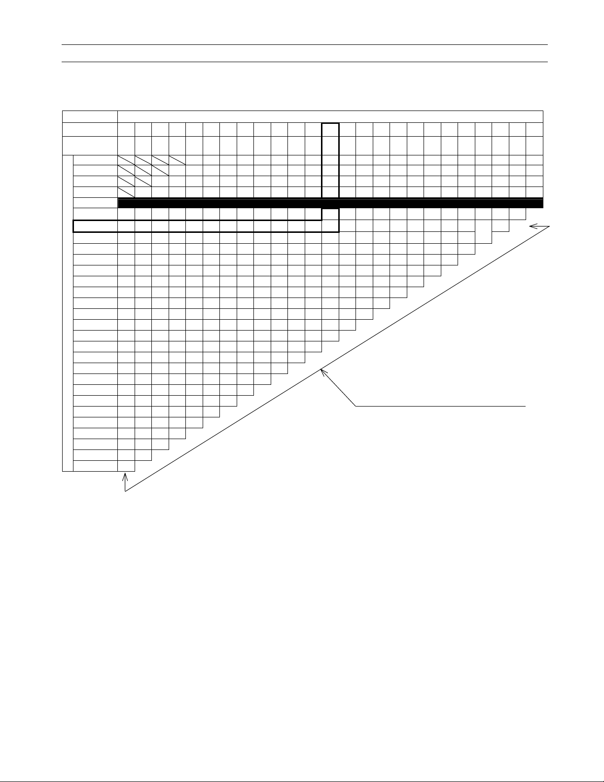
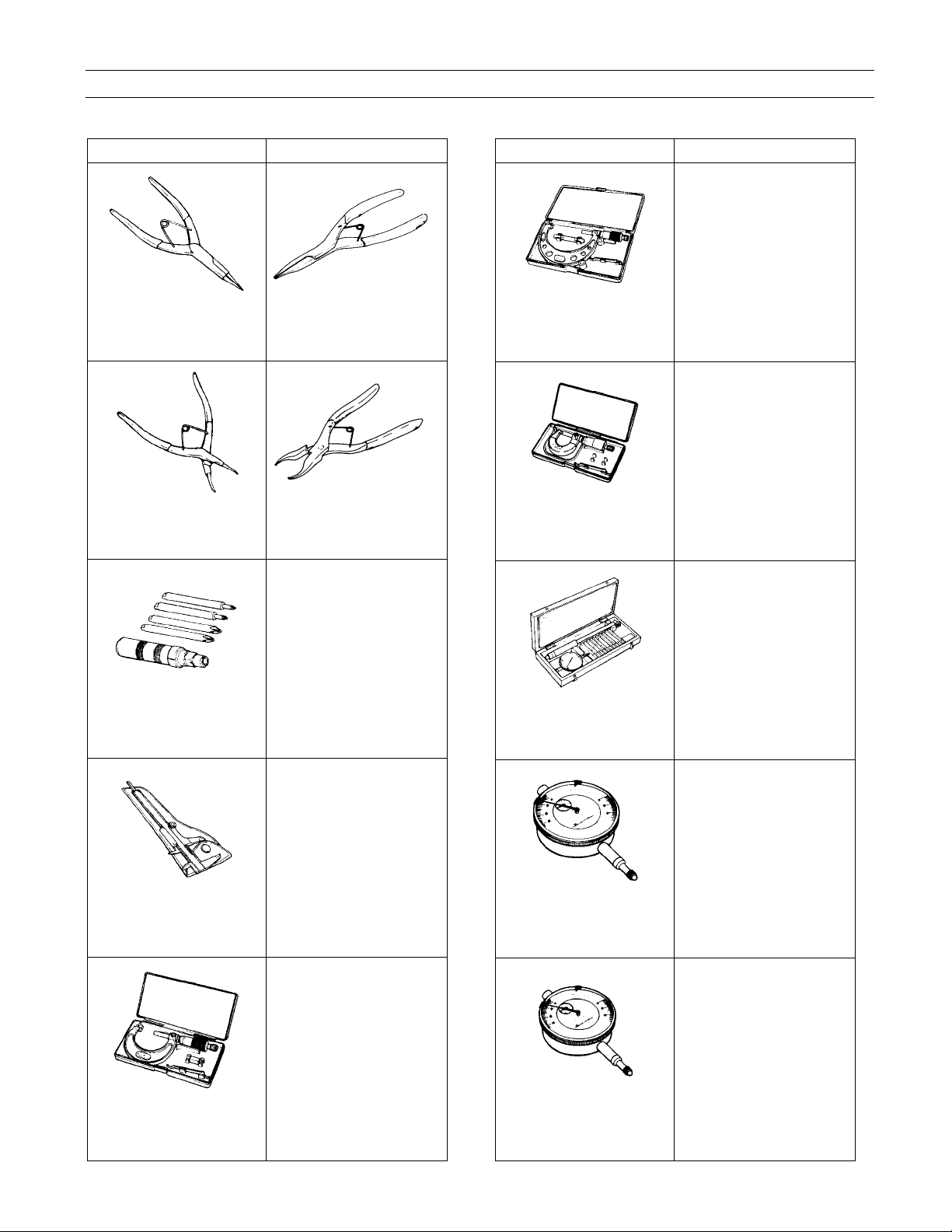
SPECIAL TOOLS
Base Manual Tools
09900-06107
Snap ring pliers
09900-06108
Snap ring pliers
Kawasaki Recommend tools
57001-144
Outside circlip pliers
57001-143
Inside circlip pliers
Base Manual Tools
09900-20204
Micrometer
(75 ~ 100 mm)
09900-20205
Micrometer
(0 ~ 25 mm)
Kawasaki Recommend tools
A suitable
commercially available
micrometer (75 ~ 100
mm)
A suitable
commercially available
micrometer (0 ~ 25
mm)
09900-09004
Impact driver set
09900-20101 or
09900-20102
Vernier calipers
09900-20202
Micrometer
(25 ~ 50 mm)
A suitable
commercially available
impact driver set
A suitable
commercially available
vernier calipers
(150 mm)
A suitable
commercially available
micrometer (25 ~ 50
mm)
09900-20508
Cylinder gauge set
09900-20602
Dial gauge
(1/1000 mm, 1 mm)
09900-20607
Dial gauge
(1/100 mm, 10 mm)
A suitable
commercially available
cylinder gauge set
A suitable
commercially available
dial gauge (1/1000
mm, 1 mm)
A suitable
commercially available
dial gauge (1/100 mm,
10 mm)
Page 30
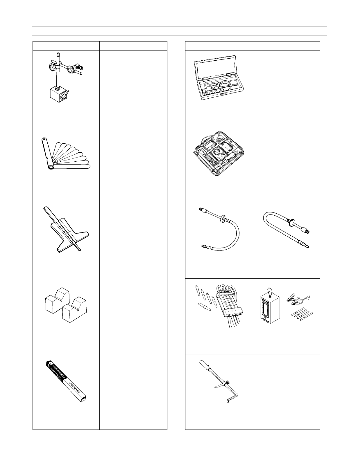
SERVICING INFORMATION 8-3
Base Manual Tools
09900-20701
Magnetic stand
09900-20803
09900-20806
Thickness gauge
Kawasaki Recommend tools
A suitable
commercially available
magnetic stand
A suitable
commercially available
thickness gauge
Base Manual Tools
09900-22403
Small bore gauge
(18 ~ 35 mm)
09900-25008
Multi circuit tester set
Kawasaki Recommend tools
A suitable
commercially available
small bore gauge (18 ~
35 mm)
A suitable
commercially available
digital multi meter for a
diode tester, peak
voltage adapter (Kowa
Seiki KEK-54-9-B) and
tachometer
09900-20805
Tire depth gauge
09900-21304
V-block set (100 mm)
09900-22301
09900-22302
Plastigauge
A suitable
commercially available
tire depth gauge
A suitable
commercially available
V-block set (100 mm)
A suitable
commercially available
plastigage (0.025 ~
0.076 mm)
09910-10750
Compression gauge
adapter
09913-13121
Carburetor balancer
set
09913-50121
Oil seal remover
57001-1317
Compression gauge
adapter, M10 1.0
57001-1369
Digital vacuum gauge
A suitable
commercially available
tool
Page 31

SERVICING INFORMATION 8-4
Base Manual Tools
09913-60230
Journal bearing
remover/installer
09913-60240
Journal bearing holder
Kawasaki Recommend tools
57001-S065
Journal bearing
remover/installer
57001-S066
Journal bearing holder
Base Manual Tools
09915-72410
Oil pressure gauge
attachment
09915-74521
Oil pressure gauge
hose
Kawasaki Recommend tools
57001-S068
Oil pressure gauge
attachment
57001-S058
Oil pressure gauge
hose
09913-70210
Bearing installer set
09915-40610
Oil filter wrench
09915-64510
Compression gauge
set
57001-1129
Bearing driver set
57001-S067
Oil filter wrench
57001-221
Compression gauge,
20 kgf/cm
2
09915-74532
Oil pressure gauge
adapter
09915-77331
Meter (for high
pressure)
09916-10911
Valve lapper set
57001-S069
Oil pressure gauge
adapter
57001-164
Oil pressure gauge,
10 kgf/cm
2
A suitable
commercially available
valve lapper
Page 32

SERVICING INFORMATION 8-5
Base Manual Tools
09916-14510
Valve spring
compressor presser
09916-14910
Valve spring
compressor attachment
Kawasaki Recommend tools
57001-241
Valve spring
compressor assembly
57001-1586
Valve spring compressor
adapter, I24
Base Manual Tools
09916-24810
Valve seat cutter
(N-626)
09916-27710
Valve seat cutter
(N-211)
Kawasaki Recommend tools
57001-S072
Valve seat cutter
(N-626)
57001-S073
Valve seat cutter
(N-211)
09916-21111
Valve seat cutter set
09916-24480
Solid pilot
(N-140-5.5 mm)
09916-24210
Valve seat cutter
(N-615)
57001-S011
Valve seat cutter set
57001-S070
Solid pilot
(N-140-5.5 mm)
57001-S071
Valve seat cutter
(N-615)
09916-34542
Reamer handle
09916-34550
Valve guide reamer
(5.5 mm)
09916-34580
Valve guide reamer
(10.8 mm)
57001-S014
Reamer handle
57001-1079
Valve guide reamer,
Ǿ5.5
57001-S039
Valve guide reamer,
(10.8 mm)
Page 33

SERVICING INFORMATION 8-6
Base Manual Tools
09916-44910
Valve guide
remover/installer
09916-53340
Attachment
Kawasaki Recommend tools
57001-1021
Valve guide arbor,
Ǿ5.5
57001-S074
Attachment
Base Manual Tools
09920-53740
Clutch sleeve hub
holder
09921-20240
Bearing remover set
Kawasaki Recommend tools
57001-1243
Clutch holder
57001-1058
Oil seal & bearing
remover
09916-84511
Tweezers
09917-47010
Vacuum pump gauge
09920-13120
Crankcase
separating tool
A suitable
commercially available
tweezers
A suitable
commercially
available tool
57001-1362
Crankcase splitting
tool assembly
09922-22711
Drive chain cutting and
joining tool
09923-73210
Bearing remover
09923-74511
Bearing puller
A suitable commercially
available tool
57001-S037
Bearing Remover,
I 17 Max.
57001-1058
Oil seal & bearing
remover
Page 34

SERVICING INFORMATION 8-7
Base Manual Tools
09924-74570
Final drive gear bearing
installer/remover
09924-84510
Bearing installer set
Kawasaki Recommend tools
57001-S075
Final drive gear bearing
installer/remover
57001-S044
Bearing Installer Set
Base Manual Tools
09930-11940
Bit holder
09930-11950
Tor x wr enc h
Kawasaki Recommend tools
A suitable
commercially
available tool
A suitable
commercially
available tool
09924-84521
Bearing installer set
09925-18011
Steering bearing
installer
09930-11920
Torx bit JT40H
57001-S023
Bearing Installer Set
57001-137
Steering Stem
Bearing Driver
A suitable
commercially
available tool
09930-30102
Sliding shaft
09930-30450
Rotor remover
09930-44541
Rotor holder
57001-1058
Oil seal & bearing
remover
57001-S076
Rotor remover
57001-S077
Rotor holder
Page 35

SERVICING INFORMATION 8-8
Base Manual Tools
09930-73110
Starter torque limiter
holder
09930-73120
Starter torque limiter
socket
Kawasaki Recommend tools
57001-S078
Starter torque limiter
holder
57001-S079
Starter torque limiter
socket
Base Manual Tools
09940-14960
Steering nut wrench
socket
09940-14990
Engine mounting thrust
adjuster socket wrench
Kawasaki Recommend tools
57001-S083
Steering nut wrench
socket
57001-S084
Engine mounting thrust
adjuster socket wrench
09930-82710
Mode selection switch
09940-14911
Steering stem nut
wrench
09940-14940
Swingarm pivot thrust
adjuster socket wrench
57001-S080
Mode selection switch
57001-S081
Steering stem nut
wrench
57001-S082
Swingarm pivot thrust
adjuster socket wrench
09940-40211
Fuel pressure gauge
adapter
09940-40220
Fuel pressure gauge
hose attachment
09940-52841
Front fork inner rod
holder
57001-S085
Fuel pressure gauge
adapter
57001-S086
Fuel pressure gauge
hose attachment
57001-S087
Front fork inner rod
holder
Page 36

SERVICING INFORMATION 8-9
Base Manual Tools
09940-52861
Front fork oil seal
installer set
099340-92720
Spring scale
Kawasaki Recommend tools
57001-S034
Front fork oil seal
installer set
A suitable commercially
available spring scale
Base Manual Tools
09941-54911
Bearing outer race
remover
09943-74111
Fork oil level gauge
Kawasaki Recommend tools
57001-1107
Head pipe outer race
remover
57001-1290
Fork oil level gauge
09941-34513
Steering race installer
57001-1129
Bearing driver set
09944-28320
HEXAGON BIT
NOTE
{When ordering a special tool, please confirm whether it is available or not.
A suitable
commercially
available tool, Hex 19
Page 37

SERVICING INFORMATION 8-10
Page 38

EMISSION CONTROL INFORMATION 9-1
Emission Control Information
Contents
EMISSION CONTROL SYSTEMS ................................................................................Base Manual
FUEL INJECTION SYSTEM ...................................................................................... Base Manual
CRANKCASE EMISSION CONTROL SYSTEM........................................................ Base Manual
EXHAUST EMISSION CONTROL SYSTEM (PAIR SYSTEM) .................................. Base Manual
NOISE EMISSION CONTROL SYSTEM ................................................................... Base Manual
EVAPORATIVE EMISSION CONTROL SYSTEM (Only for E-33)............................. Base Manual
PAIR (AIR SUPPLY) SYSTEM INSPECTION ............................................................... Base Manual
PAIR (AIR SUPPLY) SYSTEM HOSE ROUTING.......................................................... Base Manual
HEATED OXGEN SENSOR (HO
HEATED OXGEN SENSOR WIRE ROUTING .............................................................. Base Manual
EVAPORATIVE EMISSION CONTROL SYSTEM INSPECTION (Only for E-33) .........Base Manual
CANISTER HOSE ROUTING (Only for E-33) ............................................................... Base Manual
S) INSPECTION....................................................... Base Manual
2
Page 39

EMISSION CONTROL INFORMATION 9-2
Page 40

Base Manual
Suzuki DL1000
Note: Use the Kawasaki Service Manual Supplement along with the Suzuki
Base Manual when servicing the Kawasaki KLV1000-A1 models.
Page 41

Page 42

FOREWORD
This manual con tains an intro ducto ry de scri ption o n
the SUZUK I DL1000 and procedu res for its inspe ction/service and ov erhau l of its main com ponents .
Other info rm ation co ns ider ed as ge ner ally kno wn is
not included.
Read the GENERAL INFORMATION section to
familiarize yourse lf with the motorcycle and its maintenance. U se this s ection as well as o ther sectio ns
to use as a guide for proper inspection and service.
This manua l will help you k now the motor cycle better so that you can assure your customers of fast
and reliable service.
GROUP INDEX
GENERAL INFORMATION
PERIODIC MAINTENANCE
ENGINE
1
2
3
* Th is manu al has been p repared on the ba sis
of the latest specifications at the time of publication. If modifications have been made since
then, differen ces may exi st betwe en the c ontent of this manual and the actual motorcycle.
* Illustr ations in this manual are used to show
the basic principles of operation and work
procedures. They may not represent the
actual motorcycle exactly in detail.
* Th is manual is written for pe rsons who have
enough know ledg e, s kills a nd tools, i nclud in g
special tools, for se rvicing SUZUKI motorc ycles. If you do not have the proper knowledge
and tools, ask your authorized SUZUKI
motorcycle dealer to help you.
#
Inexperienced mechanics or mechanics
without the proper tools and equipment
may not be able to properly perform the
services described in this manual.
Imprope r repair may result in in jury to the
mechanic and may render the motorcycle
unsafe fo r the rider and passenger.
FI SYSTEM
COOLING AND LUBRICATION
SYSTEM
CHASSIS
ELECTRICAL SYSTEM
SERVICING INFORMATION
EMISSION CONTROL
INFORMATION
DL1000K3 (’03-MOD EL)
DL1000K4 (’04-MOD EL)
4
5
6
7
8
9
10
11
© COPYRIGHT SUZUKI MOTOR CORPORATION 2002
WIRING DIAGRAM
12
Page 43

HOW TO USE THIS MANUAL
TO LOCATE WHAT YOU ARE LOOKING FOR:
1. The text of this manual is divided into sections.
2. The section titles are listed in the GR OUP INDEX.
3. Holding the manual as shown at the right will allow you to find
the first page of the section easily.
4. The contents are liste d on the first page of each section t o
help you find the item and page you need.
COMPONENT PARTS AND WORK TO BE DONE
Under the name of each system or unit, is its explod ed view. Work instructions and other servi ce information
such as the tightening torque, lubricating points and locking agent points, are provided.
Example: Front wheel
Brake disc
Dust seal
!
Bearing
"
Center spacer
#
Coller
$
Front wheel
%
Tire valve
)
Front axle
*
Brake disc bolt
(
ITEM N·m kgf-m lb-ft
)
*
100 10.0 72.5
23 2.3 16.5
Page 44

SYMBOL
Listed in th e t able b elow ar e th e sy m bols i ndic ating ins truc tions a nd othe r in for matio n ne ces sar y for ser vicing. The meaning of each symbol is also included in the table.
SYMBOL DEFI NITION SYMBOL DEFINITION
Torque control required.
Data beside it indicates specified
torque.
Apply oil. Use engine oil unless other wise specified.
Apply molybdenum oil solution.
(Mixture of engine oil and SUZUKl
MOLY PASTE in a ratio of 1 : 1)
Apply SUZUKI SUPER GREASE “A”.
99000-25010
Apply SU Z U KI M OLY PASTE.
99000-25140
Apply SU Z U KI BOND “1207B”
99000-31140
Apply THREAD LOCK SUPER “1360”.
99000-32130
Use engine coolant.
99000-99032-11X
Use fork oil.
99000-99001-SS8
Apply or use br ake fluid.
Measur e in vo ltage range.
Measu re in current range.
Apply SU Z U KI BOND “1215”.
99000-31110
Apply THREAD LOCK SUPER “1303”.
99000-32030
Apply THREAD LOCK SUPER “1322”.
99000-32110
Apply THREAD LOCK “1342”.
99000-32050
Measu re in diode test range.
Measu re in continuity t es t range.
Use special tool.
Indication of service data.
Page 45

ABBREVIATIONS USED IN THIS
MANUAL
A
ABDC : After Bottom Dead Center
AC : Alt ernating Current
ACL : Air Cleaner, Air Cleaner Box
API : American Petroleum Institute
ATDC : After Top Dead Center
ATM Pressure: Atmospheric Pressure
Atmospheric Pressure Sensor
(APS)
A/F : Air Fuel Mixture
B
BBDC : Before Bottom Dead Cente r
BTDC : Before Top Dead Center
B+ : Battery Positive Voltage
C
CKP Sensor : Crankshaft Position Sensor
(CKPS)
CKT : Circuit
CLP Switch : Clutch Lever Position Switch
(Clutch Switch)
CMP Sensor : Camshaft Position Sensor
(CMPS)
CO : Carbon Monoxide
CPU : Central Processing Unit
D
DC : Direct Current
DMC : Dealer Mode Coupler
DOHC : Double Over Head Camshaft
DRL : Daytime Running Light
E
ECM : Engine Control Module
Engine Control Unit (ECU)
(FI Control Unit)
ECT Sensor : Engine Coolant Temperature
Sensor (ECTS), Water Temp.
Sensor (WTS)
EVAP : Evaporative Emission
EVAP
Canister
: Evaporative Emission
Canister (Canister)
F
FI : Fuel Injection, Fuel Injector
FP : Fuel Pump
FPR : Fuel Pressure Regulator
FP Relay : Fuel Pump Relay
G
GEN : Generator
GND : Ground
GP Switch : Gear Position Switch
H
HC : Hydrocarbons
I
IAP Sensor : Intake Air Pressure Sensor (IAPS)
IAT Sensor : Intake Air Temperature Sensor
(IATS)
IG : Ignition
L
LCD : Liquid Crystal Display
LED : Light Emitting Diode
(Malfunction Indicator Lamp)
LH : Left Hand
Page 46

M
MAL-Code : Malfunction Code
(Diagnostic Code)
Max : Maximum
MIL : Malfunction Indicator Lamp
(LED)
Min : Minimum
N
NOx : Nitrogen Oxides
O
OHC : Over Head Camshaft
OPS : Oil Pressure Switch
P
PCV : Positive Crankcase
Ventilation (Crankcase Breather)
R
RH : Right Hand
ROM : Read Only Memory
S
SAE : Society of Automotive Engineers
STC Syste m : Secondary Throttle Control
System (STCS)
STP Sens or : Secondary Throttle Position
Sensor (STPS)
ST Valve : Secondary Throttle Valve (STV)
STV Actuator : Secondary Throttle Valve Actuator
(STVA)
T
TO Sensor : Tip Over Sensor (TOS)
TP Sensor : Throttle Position Sensor (TPS)
V
VD : Vacuum Damper
Page 47

Page 48

GENERAL INFORMATION 1 -1
GENERAL INFORMATION
CONTENTS
WARNING/CAUTION/NOTE ...............................................................1- 2
GENERAL PRECAUTIONS ................................... ......... .......... ......... .1- 2
SUZUKI DL1000K2 (’02-MODEL) ......................................................1- 4
SERIAL NUMBER LOCATION ...........................................................1- 4
FUEL, OIL AND ENGINE COOLANT RECOMMENDATION .............1- 4
FUEL ............................................................................................1- 4
ENGINE OIL .................................................................................1- 5
BRAKE FLUID .............................................................................1- 5
1
FRONT FORK OIL .......................................................................1- 5
ENGINE COOLANT .....................................................................1- 5
WATER FOR MIXING ..................................................................1- 5
ANTI-FREEZE/ENGINE COOLANT ............................................1- 5
LIQUID AMOUNT OF WATER/ENGINE COOLANT ...................1- 5
BREAK-lN PROCEDURES .................................................................1- 6
CYLINDER IDENTIFICATION ............................................................1- 6
INFORMATION LABELS ....................................................................1- 7
SPECIFICATIONS ..............................................................................1- 8
COUNTRY AND AREA CODES .........................................................1-10
Page 49

1-2 GENERAL INFORMATION
WARNING/CAUTION/NOTE
Please read thi s manua l and follow its instruc tions carefu lly. To em phasize s pecial info rmation, the symb ol
and the words WARNIN G, CA UTION and NOTE have speci al meanings . Pay sp ecial attent ion to the mes sages highlighted by these signal words.
#
Indicates a potential hazard that could result in death or injury.
Indicates a potential hazard that could result in motorcycle damage.
NOTE:
Indicates special information to make maintenance easier or instructions clearer.
Please note , however , that the warnings and cautions contained in this manual cann ot possibly cover all
potential h azards re lating to the servic ing, or lack of servicing , of the mo torcy cle. In ad dition to the W ARN INGS and C AU TI ONS st ated , you mu s t use goo d judg em ent and bas ic m ec han ica l safety p rinci ples. If y ou
are unsure about how to perform a particular service operation, ask a more experienced mechanic for
advice.
GENERAL PRECAUTIONS
#
* Proper service and repair procedures are important for the safety of the service mechanic and
the safety and reliability of the motorcycle.
* When 2 or more persons work together, pay attention to the safety of each other.
* Wh en it is necessa ry to run the engin e indoors, make sure that exhaust gas is forced out-
doors.
* Wh en wo rking with t oxic o r f lamm a ble m at erials, m ak e s ure that t he area yo u wo rk in is well-
ventilated and that you follow all of the material manufacturer’s instructions.
* Never use gasoline as a cleaning solvent.
* To avo id getting burned, do not touch the engine, engine oil, radiator and exhaust system
until they have cooled.
* After servicing the fuel, oil, water, exhaust or brake systems, check all lines and fittings
related to the system for leaks.
Page 50

GENERAL INFORMATION 1 -3
* If parts replacement is necessary, replace the parts with Suzuki Genuine Parts or their equiva-
lent.
* Wh en rem o ving parts that are t o be reu sed, k eep the m arran ged in an orderl y m ann er so that
they may be reinstalled in the proper order and orientation.
* Be sure to use special tools when instructed.
* Make sure that all parts used in reassembly are clean. Lubricat e them when specified.
* Use the specified lubricant, bond, or sealant.
* When removing the battery, disconnect the negative cable first and then the positive cable.
* Wh en reconnect ing the bat tery, connect the positiv e cable first an d then the negative cabl e,
and replace the terminal cover on the positive terminal.
* When performing service to electrical parts, if the service procedures not require use of bat-
tery power, disconnect the negative cable the battery.
* When tightening the cylinder head and case bolts and nuts, tighten the larger sizes first.
Always tighten the bolts and nuts diagonally from the inside toward outside and to the speci-
fied tightening torque.
* Whenever you remove oil seals, gaskets, packing, O-rings, locking washers, self-locking
nuts, cotter p ins, circlips and certain other parts as specifie d, be sure to repl ace them with
new ones. Als o, before installing these new parts, be sure to remov e any left over material
from the mating surfaces.
* Never reuse a circlip. When installing a new circlip, take care not to expand the end gap larger
than required to slip the circlip over the shaft. After installing a circlip, always ensure that it is
completely seated in its groove and securely fitted.
* Us e a torq ue wrench to ti ghten f asteners to the sp ecified torque. W ipe o ff grea se and oil if a
thread is smeared with them.
* After reassembling, check parts for tightness and proper operation.
* To protect the environment, do not unlawfully dispose of used motor oil, engine coolant and
other fluids: batteries, and tires.
* To protect Earth’s natural resources, properly dispose of used motorcycle and parts.
Page 51

1-4 GENERAL INFORMATION
SUZUKI DL1000K2 (’02-MODEL )
RIGHT SIDE
* Difference betw een photographs and actual m otorcycles depends on the markets.
LEFT SIDE
SERIAL NUMBER LOCATION
The frame serial number or V.I.N . (Vehicle Identification Number)
steering head pipe. The engine s erial numbe r
bers are required especially for registering the machine and ordering spare parts.
is located on the right s ide of the cr ankcase . These nu m-
is stamped on the right side of the
FUEL, OIL AND ENGINE COOLANT RECOMMENDATION
FUEL (FOR CANADIAN MODEL)
Use only unleaded gasoline of at least 87 pump octane ( ) or 91 octane or higher rated by the research
method.
Gasoline c ontaining M TBE (Methy l Tertiary B utyl E ther), les s than 1 0% et hanol, or l ess tha n 5% met hanol
with appropriate cosolvents and corrosion inh ibitor is permissible.
FUEL (FOR OTHER COUNTRIES)
Gasoline used should be graded 91 octane (Research Method) or higher. Unleaded gasoline is recommended.
R + M
2
Page 52

GENERAL INFORMATION 1 -5
ENGINE OIL
Use a prem ium quality 4-stroke motor oil to ensure lon ger service life of you r motorc ycle. Use o nly oils w hich ar e rated SF or
SG under the API serv ice classifi cation. The recomm ended v iscosity is SAE 10W-40. If an SAE 10W-40 motor oil is not available, select an alternative according to the fol lowing chart.
BRAKE FLUID
Specificat ion an d classificat ion : DOT 4
#
Since the brake system of this motorcycle is filled with a glycol-based br ake fluid by the manufacturer, do not use or mix different types of fluid such as silicone-based and petroleum-based
fluid for refilling the system, otherwise serious d amage will result.
Do not use any brake fluid taken from old or used or unsealed containers.
Never re-use brake fluid left over fr om a previous se rvicing, which has been stored for a lo ng
period.
FRONT FORK OIL
Use fork oi l SS8 or an equivalent fork oil.
ENGINE COOLANT
Use an anti-freeze/engine coolant compatible with an aluminum radiator, mixed with distilled water only.
WATER FOR MIXING
Use distilled water only. Water other than distill e d water can corrode and clog the aluminum radiator.
ANTI-FREEZE/ENGINE COOLANT
The engine coo lant perform as a corrosion an d rust inhibitor as well as anti-freeze. Therefore, the engine
coolant should be used at all times even though the atmospheric temperature in your area does not go down
to freezing point.
Suzuki reco mmends th e use of SUZ UKI COOL ANT anti-free ze/engine coo lant. If this i s not availabl e, use
an equivalent which is compatible with an aluminum radiator.
LIQUID AMOUNT OF WATER/ENGINE COOLANT
Solution capacity (total): 2 200 ml (2.3/1.9 US/Imp qt)
For engine coolant mixture information, refer to cooling system section, page 5-2.
Mixing of anti-freeze/engine coolant should be limited to 60%. Mixing beyond it would reduce
its efficiency. If the anti-freeze/engine coo lant mixing ratio is below 50%, rust inhabiting performance is greatly reduced. Be sure to mix it above 50% even though the atmospheric temperature does not go down to the freezing point.
Page 53

1-6 GENERAL INFORMATION
BREAK-lN PROCEDURES
During m anu factur e o nly the be st po ssible mate rials a re us ed and all ma c hined par ts a re fi nish ed to a very
high standard but it is still necessary to allow the moving parts to “BREAK-IN” before subjecting the engine
to maximum stresses. The future performance and reliability of the engine depends on the care and restraint
exercised during its early life. The general rules are as follows.
• Keep to these break-in engine speed limits:
Initial 800 km ( 500 miles): Below 4 500 r/min
Up to 1 600 km (1 000 miles): Below 7 000 r/min
Over 1 600 km (1 000 miles): Be low 9 500 r/min
• Upon reaching an odometer reading of 1 60 0 km (1 000 mil es ) you can subje ct t he moto rcycl e to full thro ttle operation. However, do not exceed 9 500 r/min at any time.
CYLINDER IDENTIFICATION
The two c ylinders o f this e ngine ar e identi fied as No .1 and N o.2 c ylinder , as counted from front to rear (as
viewed by the rider on the seat).
#2
#1
Page 54

INFORMATION LABELS
Noise label (For E-03, 24, 33)
Information label (For E-03, 28, 33)
!
ICES Canada label (For E-28)
"
Vacuum hose routing label (For E-33)
#
Fuel caution label (For E-02, 24)
$
Manual notice label (For E-03, 33)
%
Tire pressure label
&
Warning safety label
'
Rear carrier warning label
Frame caution label
)
Steering warning label
*
Screen warning label
+
ID label (For E-02, 19, 24)
,
Safety label (For E-03, 28, 33)
GENERAL INFORMATION 1 -7
For E-28 (French)
For E-28
These labels are attached
on the right frame.
Page 55

1-8 GENERAL INFORMATION
SPECIFICATIONS
DIMENSIONS AND DRY MASS
Overall length.......................................................2 295 mm (90.4 in )
Overall width.................................................. ...... 865 mm (34.1 in)
Overall height.......................................................1 335 mm (52.6 in)
Wheelba se...................... ...... ...... ....... ...... ...... ......1 535 mm (60.4 in)
Ground clearance ................................................ 165 mm ( 6.5 in)
Seat height........................................................... 840 mm (33.1 i n )
Dry mass.............................................................. 207 kg (456 lbs)
209 kg (461 lbs) .........E-33
ENGINE
Type.....................................................................Four-stroke, Liquid-cooled, DOHC, 90-degree V-twin
Number of cylinders.............................................2
Bore ............................................................... ......98.0 mm (3.858 in)
Stroke...................................................................66.0 mm (2.598 in)
Piston displacement.............................................996 cm³ (60.8 cu. in)
Compression ratio................................................11.3 : 1
Fuel system..........................................................Fuel injection system
Air cleaner............................................................Non-woven fabric element
Starter system........... ...... ...... ...... ....... ...... ...... ......Electric starter
Lubrication system...............................................Wet sump
DRIVE TRAIN
Clutch...................................................................Wet multi-plate type
Transmis sion........................................................6-speed constant mesh
Gearshift pattern ..................................................1-down, 5-up
Primary reduction ratio................ .........................1.838 (57/31 )
Final reduction ratio .............................................2.411 (41/17)
Gear ratios, Low..................................................3.000 (36/12)
2nd. ....... ...... ...... ...... ....... ............ ......1.9 33 (29 /15 )
3rd ........ ............ ...... ....... ...... ...... ......1.5 00 (27 /18 )
4th......... ...... ...... ...... ....... ............ ......1.227 (27/22)
5th......... ...... ...... ...... ....... ............ ......1.086 (25/23)
Top ............. ...... ...... ............. ...... ......0.913 (21/23)
Drive chain...........................................................RK525 SMOZ7, 112 l inks
Page 56

GENERAL INFORMATION 1 -9
CHASSIS
Front suspension................................................. Inverted telescopic, coil spring, oil damped
Rear suspension ................................................. Link type, coil spring, oil damped
Steering angle..................................................... 40° (right & left)
Caster.......................... ........................................ 26° 30’
Trail ..................................................................... 111 mm (4.3 in)
Turning radi us ............. ...... ....... ...... ...... ...... ...... ... 2. 7 m (8.86 ft)
Front brake.......................................................... Disc brake, twin
Rear brake .......................................................... Disc brake
Front tire size ...................................................... 110/80 R19M/C 59H, tubeless
Rear tire size....................................................... 150/70 R17M/C 69H, tubeless
Front fork stroke.................................................. 160 mm (6.3 in)
Rear wheel travel ................................................ 159 mm (6.2 in)
ELECTRICAL
lgnition ty pe ......................................................... Electronic ignition (ECM, Transist orized)
lgnition timing ...................................................... 4° B. T. D. C at 1 200 r/min
Spark pl ug ........................................................... NGK: CR8 EK or DENSO: U24ETR
Battery................................................................. 12 V 43.2 kC (12 Ah)/10 HR
Generator............................................................ Three-phase A.C. Generator
Fuse .................................................................... 30/15/15/15/15/15/10 A
Headligh t............................................................. 12 V 60/55 W H4
Position light........................................................ 12 V 5 W × 2.........Except for E-03, 24, 28, 33
Turn signal light................................................... 12 V 10 W
License l ight ........................................................ 12 V 5 W
Brake light/Taillight.............................................. 12 V 21/5 W ×2
Speedometer/Tachometer light........................... LED
Neutral indicator light .......................................... LED
High beam indicator light..................................... LED
Turn signal indicator light .................................... LED
Over drive indicator light ..................................... LED
Fuel injector warning light ................................... LED
Engine coolant temperature warni ng light........... LED
Oil press u re warning light.................................... LED
CAPACITIES
Fuel tank ............................................................. 22 L (5.8/4.8 US/Imp gal)
Engine oil, oil change ........................................ 2 700 ml (2.9/2.4 US/Imp qt)
with filter change........................... ... 2 900 ml (3.1/2.6 US/Imp qt)
overhaul........................................... 3 300 ml (3.5/2.9 US/Imp qt)
Engine coolant, including reserve ....................... 2 200 ml (2.3/1.9 US/Imp oz)
Front fork oil (each leg) ....................................... 505 ml (17.1/17.8 US/Imp oz)
These specifications are subject to change without notice.
Page 57

1-10 GENERAL INFORMATION
COUNTRY AND AREA CODES
The following codes stand for the applicable country(-ies) and area(-s).
CODE COUNTRY or AREA
E-02
E-03
E-19
E-24
E-28
E-33
U. K.
U. S. A. (Except for California)
EU
Australia
Canada
California (U. S. A.)
Page 58

PERIODIC MAINTENANCE 2-1
PERIODIC MAINTENANCE
CONTENTS
PERIODIC MAINTENANCE SCHEDULE ............................................2- 2
PERIODIC MAINTENANCE CHART ...........................................2- 2
LUBRICATION POINTS ...............................................................2- 3
MAINTENANCE AND TUNE-UP PROCEDURES ...............................2- 4
AIR CLEANER .............................................................................2- 4
SPARK PLUG ..............................................................................2- 5
TAPPET CLEARANCE ................................................................2- 7
FUEL HOSE .................................................................................2-12
ENGINE OIL AND OIL FILTER ....................................................2-12
2
ENGINE IDLE SPEED ..................................................................2-14
THROTTLE CABLE PLAY ...........................................................2-14
THROTTLE VALVE SYNCHRONIZATION ..................................2-15
PAIR (AIR SUPPLY) SYSTEM ....................................................2-15
CLUTCH .......................................................................................2-16
COOLING SYSTEM .....................................................................2-17
DRIVE CHAIN ..............................................................................2-19
BRAKE .........................................................................................2-21
TIRE .............................................................................................2-25
STEERING ...................................................................................2-25
FRONT FORK ..............................................................................2-26
REAR SUSPENSION ...................................................................2-26
EXHAUST PIPE BOLT .................................................................2-26
CHASSIS BOLT AND NUT ..........................................................2-27
COMPRESSION PRESSURE CHECK .................................................2-29
6
COMPRESSION TEST PROCEDURE ........................................ .2-29
OIL PRESSURE CHECK ......................................................................2-30
OIL PRESSURE TEST PROCEDURE .........................................2-30
Page 59

2-2 PERIODIC MAINTENANCE
PERIODIC MAINTENANCE SCHEDULE
The chart below lists the recommended intervals for all the required periodic service work necessary to keep
the motorcyc le operating at pea k performance an d economy. Mileages are expressed in ter ms of kilometers, miles and time for your convenience.
NOTE:
More frequent servicing may be performed on motorcycles that are used under severe conditions.
PERIODIC MAINTENANCE CHART
Interval
Item
Air cleaner element — I I R I
Exhaust pipe bolts and muffler bolts T — T — T
Valve clearance — — — — I
Spark plugs — I R I R
Fuel hose — I I I I
Engine oil R R R R R
Engine oil filter R — — R —
Idle speed IIIII
Throttle cable play I I I I I
Throttle valve synchr onization I — I — I
Evaporative emission control system
(E-33 only)
PAIR(air supply)system — — I — I
Engine coolant Replace every 2 years.
Radiator hose — I I I I
Clutch hose — I I I I
Clutch fluid — I I I I
Drive chain I I I I I
Brakes IIIII
Brake hose — I I I I
Brake fluid — I I I I
Tires —IIII
Steering I — I — I
Front fork — — I — I
Rear suspension — — I — I
Chassis bolts and nuts T T T T T
km
miles
months 1 6 12 18 24
1 000 6 000 12 000 18 000 24 000
600 4 000 7 500 11 000 15 000
Replace every 4 years
(E-33 only)
—— I — I
Replace vapor hose every 4 years
Replace every 4 years
Replace every 2 years
Clean and l ublicate every 1 000 km (600 miles)
Replace every 4 years
Replace every 2 years
NOTE:
I=Inspect and clean, adjust, rep lace or lubr icate as necessary;
R=Replace; T=Tighten
Page 60

PERIODIC MAINTENANCE 2-3
LUBRICATION POINTS
Proper lubrication is important for smooth operation and long life of each working part of the motorcycle.
Major lubrication points are indicated below.
Clutch lever holder
Side-stand pivot
and spring hook
Brake lever holder
and throttle cables
Brake pedal pivot
and footrest pivot
Footrest pivot
Drive chain
NOTE:
* Before lubricating each part, clean off any rusty spots and wipe off any grease, oil, dirt or grime.
* Lubricate exposed parts which are subject to rust, with a rust preventative spray whenever the motorcycle
has been operated under wet or rainy conditions.
Page 61

2-4 PERIODIC MAINTENANCE
MAINTENANCE AND TUNE-UP PROCEDURES
This section describes the servicing procedures for each item of
the Periodic Maintenance requirements.
AIR CLEANER
Inspect every 6 000 km (4 000 miles, 6 months) and
replace every 18 000 km (11 000 miles, 18 months).
• Remove the seat. (6-4)
• Remove the fuel tank. (4-52)
• Remove the air cleaner box cap
• Remove the air cleaner element
.
.
• C arefully u se air hose to blow the dust from the cleaner element.
Always use air pressure on the throttle body side of
the air cleaner elem ent. If air pressure is used on th e
other side, dirt will be forced into the pores of the air
cleaner element thus restricting air flow through the
air cleaner element.
• Install the O-ring
• Reinstall the cleaned or new air cleaner element in the
reverse order of removal.
If driving under dusty condition, clean the air cleaner
element more frequently. The su rest way to accelerate
engine wear is to use the engine without the element
or to use a ruptured element. Make sure that the air
cleaner is in good condition at all times. Life of the
engine depends largely on this component!
properly.
Page 62

NOTE:
When clea ning the ai r cleane r elemen t, drain w ater from the air
cleaner by removing the drain plug.
SPARK PLUG
Inspect every 6 000 km (4 000 miles, 6 months) and
replace every 12 000 km (7 500 miles, 12 months).
NO.1 (FRONT) SPARK PLUG REMOVAL
• Remove the spark plug mounting bolts
" and
#.
PERIODIC MAINTENANCE 2-5
• Move the radiator forward.
• Remove the spark plug cap
NOTE:
Be careful not to damage the radiator fins.
#
The hot radia to r and the hot eng ine c an bur n you. Wai t
until the radiator and the engine are cool enough to
touch.
• Remove the spark plug with a spark plug wrench.
.
Page 63

2-6 PERIODIC MAINTENANCE
NO.2 (REAR) SPARK PLUG REMOVAL
• Remove the seat. (6-4)
• Lift and support the fuel tank. (4-51)
• Remove the spark plug cap.
• Remove the spark plug with a spark plug wrench.
HEAT RANGE
• Check to see the heat range of the plug.
Standard Cold type
NGK CR8EK CR9EK or CR10EK
DENSO U24ETR U27ETR or U31ETR
CARBON DEPOSIT
• C he ck to see if ther e ar e car bons de posi t on the plug s. If ca rbon is deposited, remove it with a spark plug cleaner machine
or carefully using a tool with a pointed end.
SPARK PLUG GAP
• Measure the plug gap with a thickness gauge. If out of specification, adjust it to the following gap.
\ 09900-20803: Thickness gauge
Spark plug gap
"
Standard: 0.6 – 0.7 mm (0.024 – 0.028 in)
ELECTRODES CO NDITION
• Check to see the worn or burnt condition of the electrodes. If it
is extremely worn or burnt, replace the plug. And also replace
the plug if it has a broken insulator, damaged thread.
Confirm the t hread si ze and reac h whe n replacing the
plug. If the r eac h is too s hort , car b on will be depo sit ed
on the screw portion of the plug hole and engine damage may result.
Page 64

SPARK PLUG AND PLUG CAP INSTALLAT ION
Before using a spark plug wrench, carefully turn the
spark plug by finger into the threads of the cylinder
head to prevent damage the aluminum threads.
• Install the spark plugs to the cylinder heads by finger tight,
and then tighten them to the specified torque.
" Spark plug: 11 N·m (1.1 kgf-m, 8.0 lb-ft)
NOTE:
When fitting the spark plug caps, front and rear, face the triangle
mark
" on the water-proof cover to each cylinder exhaust side.
TAPPET CLEARANCE
PERIODIC MAINTENANCE 2-7
Inspect every 24 000 km (15 000 miles, 24 months).
• Remove the seat. (6-4)
• Lift and support the fuel tank. (4-51)
• Remove t he fuel tank side covers, cowlings a nd inner cov er.
(6-6)
• Remove the radiator . (5-4)
• Remove the spark plugs. (2-5)
• Remove the cylinder head cover s.
The tappet clearance specification is different for intake and
exhaust valve s.
Tappet clear ance mus t be check ed and adjus ted, 1) at the time
of periodic inspection, 2) when the valve mechanism is serviced,
and 3) w hen th e cams hafts ar e dis turbed b y remo ving th em for
servicing.
Tappet clearance (when cold)
IN. : 0.10 – 0.20 mm ( 0.004 – 0.008 in)
EX. : 0.20 – 0.30 mm (0.008 – 0.012 in)
NOTE:
* The tappet clearance should be taken when each cylinder is at
Top Dead Center (TDC) of compression stroke.
* The c ams (IN & EX) on the front cylinde r at pos ition
" show
the front cylinder at TDC of compression stroke.
* The ca ms (IN & EX) on the rear cylinder at p osition
# show
the rear cyli nder at TDC of compression stroke.
* The clearance specification is for COLD state.
* To turn the crankshaft for clearance checking, be sure to use a
17-mm wren ch, and rotate in the n ormal r unning directio n. All
spark plugs should be removed.
IN.
EX.
Page 65

2-8 PERIODIC MAINTENANCE
T
• Remove the generator cover plug
plug
.
• T urn the c rank shaft to se t th e No.1 ( Front ) cy linde r a t T DC o f
compression stroke. (Align the “F | T” line on the generator
rotor to the index mark of valve timing inspection hole and
also bring the camshafts to the position as shown in page
2-7.)
• T o inspect the No.1 (Front) cylind er tappet clearance, use a
thickness gauge between the tappet and the cam. If the clearance is out of specifi cation, adjust it into the specified range.
and timing inspection
FT
\ 09900-20803: Thickness gauge
• Turn the crankshaft 270 degrees (¾ turns) to set the No.2
(Rear) cylinder at TDC of compression stroke. (Align the
“R | T” line on th e generator rotor to the index mark o f valve
timing inspection hole and also bring the camshafts to the
position as shown in page 2-7.)
• Inspect the No.2 (Rear) cylinder tappet clearance as the
same man ner of No.1 (Front) cylinder and adjust the clearance if necessary.
\ 09900-20803: Thickness gauge
RRT
RT
Page 66

TAPPET CLEARANCE ADJUSTMENT
The clearance is adjusted by replacin g the existing tappet s him
by a thicker or thinner shim.
• Remove the intake or exhaust camshafts. (3-20)
• Remove the tappet and shim by fi ngers or magnetic hand.
• Check the fi gures pri nted on the shim. Thes e figure s indicate
the thickness of the shim, as illustrated.
• Select a replacement shim that will provide a clearance within
the specified range. For the purpose of this adjustment, a total
of 25 sizes o f tappet sh im are availab le ranging fr om 2.30 to
3.50 mm in steps of 0.05 mm. Fit the selected shim to the
valve stem end, with numbers toward tappet. Be sure to
check shim size with micrometer to ensure its size.
Refer to the t app et s him sel ection tab le (Pa ges 2- 10 a nd -11)
for details.
NOTE:
* Be sure to apply engine oil to tappet shim top and bottom
faces.
* Whe n seating the tappet shim , be sure to face figure p rinted
surface to the tappet.
PERIODIC MAINTENANCE 2-9
270
2.70 mm
Reinstall the camshafts as the specified manner.
(3-105)
• After replacing the tappet shim and camshafts, rotate the
engine so that the tappet is depressed fully. Th is will squeeze
out oil trapped between the shim and the tappet that could
cause an incorrect measurement, then check the clearance
again to confirm that it is within the specified range.
• After finishing the t appet clearance adjustment, reinstall the
following items.
• When installing the cylinder head cover, do not forget the gasket
".
Page
* Cylinder head cover ........................................ 3-111
* Spark plug and plug cap.................................. 2-7
* Valve timing inspection plug............................ 3-111
* Generator cover plug....................................... 3-112
Page 67

2-10 PERIODIC MAINTENANCE
(INTAKE SIDE)
Page 68

(EXHAUST SIDE)
PERIODIC MAINTENANCE 2-11
Page 69

2-12 PERIODIC MAINTENANCE
FUEL HOSE
Inspect every 6 000 km (4 000 m iles, 6 months).
Replace every 4 years.
Inspect the fuel feed hose
any defects are found , the fuel hoses must be replaced.
" for damag e and fuel leakage. If
ENGINE OIL AND OIL FILTER
(ENGINE OIL)
Replace in itially at 1 000 km (600 miles, 1 month) and
every 6 000 km (4 000 miles, 6 months) thereafter.
(OIL FILTER)
Replace in itially at 1 000 km (600 miles, 1 month) and
every 18 000 km (11 000 miles, 18 months) t hereafter.
Oil should be changed while the engine is warm. Oil filter
replacement at the above intervals, should be done together
with the engine oil ch ange.
ENGINE OIL REPLACEMENT
• Keep the motorcycle upright.
• Pl ace an oil p an below the e ngine, a nd dr ain oil b y remo ving
the drain plug
and filler cap
.
• Tighten the drain plug
fresh oil th rou gh the oil fille r. T he eng ine w ill hol d abo ut 2 .7 L
(2.9/2.4 US /Imp qt) of oi l. Use an API cl assification of S F or
SG oil with SAE 10W-40 viscosity.
" Oil drain plug: 23 N·m (2 .3 kg-m, 16.5 lb-ft)
to the specified torque, and pour
Page 70

• Start up the engine a nd allow it to run for s everal min utes at
idling speed.
• Turn off the engine and wait about one minute, then check the
oil level through the inspection window
". If the level is below
mark “L”, add oil to “F” level. If the level is above mark “F”,
drain oil to “F” level.
OIL FILTER REPLACEMENT
• Remove the engine under cover
.
• Drain engine oil in the same manner of engine oil replacement
procedure.
• Remove the oil f ilter
by using the oil filter wrenc h. (Special
tool)
• Apply eng ine oil lightly to the gasket of the new filter before
installation.
• Install the new filter turning it by hand until you feel that the filter gasket contacts the mounting surface. Then tighten it 2
turns usi ng the oil filter wrench.
PERIODIC MAINTENANCE 2-13
\ 09915-40610: Oil filter wrench
NOTE:
To properly tigh ten the filter, use the spec ial tool. Never tighte n
the filter by hand.
• Pour fresh engine oil and check the oil level in the same manner of engine oil replacement procedure.
Engine oil capacity
Oil change: 2.7 L (2.9/2.4 US/Imp qt)
Filter change: 2.9 L (3.1/2.6 US/Im p qt)
Overhaul engine: 3.3 L (3.5/2.9 US/Imp qt)
ONLY USE A GENUINE SUZUKI MOTORCYCLE OIL
FILTER. Other manufacturer’s oil filters may differ in
thread spe cifications (thread diameter and pitch), filtering performance and durability which may lead to
engine dama ge or oi l lea ks. Als o, do not use a genu i ne
Suzuki automobile oil filter on this motorc ycle.
After contcting the gasket,
tighten 2 turns.
Page 71

2-14 PERIODIC MAINTENANCE
ENGINE IDLE SPEED
Inspect initially at 1 000 km (600 mile s, 1 month ) and
every 6 000 km (4 000 miles, 6 months) thereafter.
NOTE:
Make this adjustment when the engine is hot.
• Start up the engine and set its idle speed to the specified
range by turning the throttl e stop scr ew
Engine idle speed: 1 200 ± 100 r/min
".
THROTTLE CABLE PLAY
Inspect initially at 1 000 km (600 mile s, 1 month ) and
every 6 000 km (4 000 miles, 6 months) thereafter.
Adjust the throttle cabl e play
MINOR ADJUSTMENT
First step:
• Remove cable adjuster covers
• L oosen the locknut
turn in the adjuster
Second step:
• Loosen the locknut
• T urn the adjuster
should b e 2.0 – 4.0 mm (0.08 – 0.16 in) at the throttle grip.
• Tighten the locknut
Third step:
• While holding the throttle grip at the fully closed position,
slowly turn out the adjuster
to feel resistance.
• Tighten the locknut
Throttle cable play
#
After the a djustmen t is co mplet ed, chec k that h andlebar movement does not raise the engine idle speed
and that the throttle grip returns smoothly and automatically.
fully into the threads.
of the throttle pulling cable
in or out u ntil the throttle cable pl ay
while holding the adjuster
while holding the adjuster
" with the following three steps.
#.
of the throttle returning cable
.
.
of the throttle returning cable
.
": 2.0 – 4.0 mm (0.08 – 0.16 in)
and
"
NOTE:
Major adjustment can be made by the throttle body side
adjuster.
Page 72

MAJOR ADJUSTMENT
• Remove the fuel tank. (4-52)
• Remove the air cleanet box. (4-60)
• Loosen the locknut
• Turn the returning cable adjuster
play.
• Loosen the locknut
• Turn the pulling cable adjuster
cable play
throttle grip.
• Tighten the locknut
" should b e 2.0 – 4.0 m m (0.08 – 0.16 in) at the
of the throttle returning cable.
to obtain proper cable
of the throttle pulling cable.
in or out until the throttle
securely while holding the adjuster
PERIODIC MAINTENANCE 2-15
.
Throttle cable play
• While holding the throttle grip at the fully closed position,
slowly tur n the retur ning ca ble a djus ter
1.0 mm (0.04 in).
• Tighten the locknut
#
After the adjustment is completed, cheack that handlebar movem ent does not raise the eng ine idl e speed
and that the throttle grip returns smo othly and automatically.
": 2.0 – 4.0 mm (0.08 – 0.16 in)
to obtain a slack of
securely.
THROTTLE VALVE SYNCHRONIZATION
Inspect every 12 000 km (7 500 miles, 12 months).
(4-72)
PAIR (AIR SUPPLY) SYSTEM
Inspect every 12 000 km (7 500 miles, 12 months).
(9-6)
Page 73

2-16 PERIODIC MAINTENANCE
CLUTCH
(CLUTC H HOS E AND CL UT C H FLU ID)
Inspect every 6 000 km (4 000 m iles, 6 months).
Replace hose every 4 years.
Replace fluid every 2 years.
CLUTCH FLUID LEVEL
• Keep the motorcycle upright and place the handlebars
straight.
• Check the clutch fluid level by observing the lower limit line on
the clutch fluid reservoir.
• If the level is found to be lower than the lower mark, replenish
with BRAKE FLUID that the following specification.
O Specification and Classification: DOT 4
#
The clutch system of this motorcycle is filled with a
glycol-base d brake fluid. Do not use or mix different
types of fluid such as silicone-based or petroleum
based. Do not use an y bra ke f lu i d take n f rom ol d, us ed
or unsealed containers. Never re-use brake fluid left
over from the last servicing or stored for a long periods. Check t h e clut ch ho se an d hose join ts fo r crac ks
and oil leakage.
BLEEDING AIR FROM THE CLUTCH FLUID CIRCUIT
The clutch fluid circuit may be purged of air in the following manner.
• Keep the motorcycle upright and place the handlebars
straight.
• F ill up the master cylinder reservoir to the upper end of the
inspection window. Replace the reser voir cap to prevent entry
of dirt.
• At tach a pipe to the bleed er valve and inser t the free end of
the pipe into a receptacle.
• Sq ueeze and relea se the clutch lever several times in rapid
succession , and squeeze th e lever fully without releasing it.
Loosen the bleeder valve by turning it a quart er of a turn so
that the fluid runs into the receptacle; this will remove the tension of the c lutc h lever ca us ing it to tou c h the han dleba r gr ip.
Then, close the valve, pump and squeeze the lever, and open
the valve. Repeat this process until the fluid flowing into the
receptacle no longer contains air bubbles.
• C los e the bleed er valve , and disco nne ct the p ip e. Fi ll the re servoir w ith brake fluid to the upper en d of th e insp ection window.
" Air bleeder valve: 7.5 N·m (0.75 kg-m, 5.5 lb-ft)
Page 74

COOLING SYSTEM
Inspect every 6 000 km (4 000 m iles, 6 months).
Replace engine coolant every 2 years.
ENGINE COOLANT LEVEL CHECK
• Keep the motorcycle upright.
• Check the engine coolant level by observing the full and lower
lines on the engine coolant reserve tank.
" Full line
• If the lev el is below t he lower li ne, add eng ine coolant to the
full line from the e ngine c oolan t rese rve t ank fi ller. T o rem ov e
the filler cap, remove the right fuel tank side cover. (6-4)
# Lower line
PERIODIC MAINTENANCE 2-17
ENGINE COOLANT CHANGE
• Remove the right fuel tank side cover. (6-4)
• Remove the radiator cap
• Drain engine coolant by removing the drain bolts
#
* Do not open the radiator cap when the engine is hot,
as you may be injured by escaping hot liquid or
vapor.
* Engine coolant may be harmful if swallowed or if it
comes in cont ac t with sk in or eye s. If engin e coo lan t
gets into the eyes or in contac t with the skin, flush
thoroughly with plenty of water. If swallowed, induce
vomiting and call physician immediately!
• Flush the radiator with fresh water if necessary.
• Tighten the water drain bolts
" Water drain bolt
• Pour the specified engine coolant up to the radiator inlet.
• Bleed the a ir from the eng ine coo lant circu it as follow ing p rocedure.
": 13 N·m (1.3 kgf-m, 9.5 lb-ft)
#: 5.5 N·m (0.55 kgf-m, 4.0 lb-ft)
.
" and
" and
# to the specified torque.
#.
NOTE:
For engine coolant information, refer to page 5-2.
Page 75

2-18 PERIODIC MAINTENANCE
AIR BLEEDING THE ENGINE COOLANT CIRCUIT
• Bleed air from the air bleeder bolt
• Tighten the air bleeder bolt
.
to the specified torque.
" Air bleeder bolt: 13 N·m (1.3 kgf-m, 9.5 lb-ft)
• Add engine coolant up to the radiator inlet.
• Support the motorcycle upright.
• Lightly tap the thermostat case
cycle, right and left, to bleed the air trapped in the c ase
and slowly swing the motor-
.
• Add engine coolant up to the radiator inlet.
• St art up the eng ine and b leed air fr om the radiato r inlet c ompletely.
• Add engine coolant up to the radiator inlet.
• R ep eat th e ab ove pr oced ur e un til blee d no air from the r adiator inlet.
• Close the radiator cap
securely.
• Af ter w armi ng u p a nd cooli ng down t he e ngi ne sever al ti m es,
add the engine coolant up to the full level of the reserve tank.
Repeat th e above procedu re several times a nd make
sure that the radiator is filled with engine coolant up to
the reserve tank full level.
Engine coolant capacity
Reverse tank side : 250 ml (0.3/0.2 US/lmp qt)
Engine side : 1 950 ml (2.1/1.7 US/lmp qt)
Page 76

RADIATOR HOSES
Check to see the radiator hoses for crack, damage or engine
coolant leakage.
If any defects are found, replace the radiator hoses with new
ones.
DRIVE CHAIN
Inspect initially at 1 000 km (600 m iles, 1 mon th) and
every 6 000 km (4 000 miles, 6 months) thereafter.
Clean and Lubricate every 1 000 km (600 miles).
Visually check the drive chain for the possible defects listed
below. (Su pport the motorc ycle by a jack and a wooden block,
turn the r ea r wh eel sl ow ly by han d with the tr an smi ssion shi fte d
to Neutral.)
* Loose pins * Excessive wear
* Damaged rollers * Improper chain adjustment
* Dry or rusted links * Missing O-ring seals
* Kinked or binding links
PERIODIC MAINTENANCE 2-19
Grease
“O” ring
If any defects are found, the drive ch ain must be replac ed .
NOTE:
When replacing the drive chain, replace the drive chain and
sprockets as a set.
CHECKING
• Remove the axle cotter pin. (For E-03, 28 and 33 models)
• Loosen the axle nut
• Loosen the chain adjuster locknuts
• Tense the drive chain fully by turning both chain adjusters
.
.
.
Page 77

2-20 PERIODIC MAINTENANCE
• C ount out 21 pins (20 pi tches) on the chain and measure th e
distance be tween the tw o points. If the distance exce eds the
service limit, the cha in must be replaced.
Drive chain 20-pitch length
Service Limit: 319.4 mm (12.6 in)
ADJUSTING
• L oosen or tight en both ch ain adjusters
until the chain has
20 – 30 mm (0.8 – 1.2 in) of slack in the middle between
engine an d r ea r sp roc kets. T he en ds o f l eft an d r ight s pace rs
must be at the same po sition on th e scale s
" to ensure that
the front and rear wheels are correctly aligned.
• Place the motorcycle on its side-stand for accurate adjustment.
• Af ter adjusting th e drive chain, tight en the axle nut
to the
specified torque.
20 – 30 mm
(0.8 – 1.2 in)
• R eche c k the drive chain slac k after tighte ning the ax le nut
• Tighten both chain adjus ter locknuts
sec u r e ly.
" Rear axle nut: 100 N·m (10.0 kgf-m, 72.5 lb-ft)
.
Page 78

CLEANING AND LUBRICATING
• Wash the chain with kerosene. If the chain tends to rust
quickly, the intervals must be shortened.
Do not use trichlene, gasoline or any similar fluids:
These fluids have too great a dissolving power for this
chain and, what is more importan t, they can damage
the “O”-rings (or seals) confining the grease in the
bush to pin clearance. Remember, high durability
comes fro m the presence of grease in that clearance.
• After wa shing an d dryi ng the chain , oil it with a h eavy- weight
motor oil.
* Do not use any oil sold commercially as “drive chain
oil”. Such oil can damage the “O”-ri ngs (or seals).
* The standard drive chain is RK525SMOZ7. SUZUKI
recommends that this standard drive chain should
be used for the replacement.
PERIODIC MAINTENANCE 2-21
BRAKE
(BRAKE)
Inspect initially at 1 000 km (600 m iles, 1 mon th) and
every 6 000 km (4 000 miles, 6 months) thereafter.
(BRAKE HOSE AND BRAKE FLUID)
Inspect every 6 000 km (4 000 miles, 6 months).
Replace hoses every 4 years. Replace fluid every 2
years.
BRAKE FLUID LEVEL CHECK
• Keep the motorcycle upright and place the handlebars
straight.
• Check the br ake fluid level by ob serving the lower limit l ines
on the front and rear brake fluid reservoirs.
• When the level is below the lower limit line, replenish with
brake fluid that meets the following specification.
O Specification and Classification: DOT 4
UPPER
LOWER
Page 79

2-22 PERIODIC MAINTENANCE
#
The brake system of this motorcycle is filled with a
glycol-base d brake fluid. Do not use or mix different
types of fluid such as silicone-based or petroleum-based. Do not use any brake fluid taken from
old, used o r unsealed contain ers. Never re-use brake
fluid left over from the last servicing or stored for a
long period.
#
Brake fluid, if it leaks, will interf ere with safe runnin g
and immediately discolor painted surfaces. Check the
brake hoses and hose joints for cracks and oil leakage
before riding.
• Remove the brake calip er. (Front)
BRAKE PADS
The extent o f brake pad wear can be checke d by obse rving the
grooved limit
" on the pad. When the wear exceeds the
grooved limit, replace the pads with new ones. (6-57, 67)
Replace the brake pad as a set, otherwise braking performance will be adversely affected.
Page 80

BRAKE PEDAL HEIGHT
• Loosen t he locknut
brake pedal 20 – 30 mm (0.8 – 1.2 in)
the footrest.
• Retighten the locknut
proper position.
and rotate the push rod
to secure the push rod
PERIODIC MAINTENANCE 2-23
to locate
" below the top face of
in the
Brake pedal height
" Rear brake master cylinder rod locknut
BRAKE LIGHT SWITCH
Adjust the rear brake light switch so that the brake light will
come on just before pressure is felt when the brake pedal is
depressed.
": 20 – 30 mm (0.8 – 1.2 in)
:
18 N·m (1.8 kgf-m, 13.0 lb-ft)
Page 81

2-24 PERIODIC MAINTENANCE
AIR BLEEDING THE BRAKE FLUID CIRCUIT
Air trapped in the fluid circuit acts like a cushion to absorb a
large proport ion of the pressu re developed by the master cylinder and thus inte rferes with the full brak ing performance of th e
brake calipe r. The presence of air is indicated b y “sponginess”
of the brake lever and also by lack of brak ing for ce. Con sid erin g
the dange r to whi ch such trapped a ir exp oses the m achine and
rider, it is es sential that , after remou nting the br ake and resto ring the brake system to the normal condition, the brake fluid circuit be purged of air i n the following manner:
• Fill up the master cylinder reservoir to the “UPPER” line.
Place the reservoir cap to prevent entry of dirt.
• At tach a p ipe to the air blee der val ve, and inse rt the free en d
of the pipe into a receptacle.
" Air bleeder valve: 7.5 N·m (0.75 kgf-m, 5.5 lb-ft)
• Front brake: B leed the air from the air bleeder valve.
• Sq ueeze and release the brake lever several times in rapid
succession and squeeze the lever fully without releasing it.
Loosen the bleeder valve by turning it a quart er of a turn so
that the brake fluid runs i nto the recep tacle; this will r emove
the tensi on of the brake l ever causing it to touch th e handlebar grip. The n, close th e valve, pu mp and s queeze th e lever ,
and open the valve. Rep eat this pr oces s unti l the flui d flow ing
into the receptacle no longer contains air bubbles.
NOTE:
Replenish the brake fluid in the reservoir as necessary while
bleeding the brake system. Make sure that there is always some
fluid visible in the reservoir.
• C los e the bleed er valve , and disco nne ct the p ip e. Fi ll the re servoir with brake fluid to the “UPPER” line.
Handle brake fluid with care: the fluid reacts chemically with paint, plastics, rubber materials and so on.
• The only difference between bleeding the front and rear
brakes is that the rear master cyl inder is actuated by a pedal.
Page 82

TIRE
Inspect every 6 000 km (4 000 m iles, 6 months).
TIRE TREAD CONDITION
Operating the motorcycle with excessively worn tires will
decrease riding stability and consequently invite a dangerous
situation. It is highly recommended to replace a tire when the
remaining depth of tire tread reaches the follow ing specification.
\ 09900-20805: Tire depth gauge
Tire tread depth
Service Limit (FRONT): 1.6 mm (0.06 in)
(REAR) : 2.0 mm (0.08 in)
TIRE PRESSURE
If the tire pressure is too high or too low, steering will be
adversely a ffected an d tire w ear inc reased . Therefo re, main tain
the correc t tire pressure fo r good roadability or shorter tire li fe
will result. Cold inflation tire pressure is as follows.
PERIODIC MAINTENANCE 2-25
COLD INFLATION
TIRE PRESSURE
FRONT 250 2.50 36 250 2.50 36
REAR 250 2.50 36 280 2.80 41
The standard tire fitted on this motorcycle is 110/80
R19M/C (59H) for front and 150/70 R17M/C (69H) for
rear. The use of tires other than those specified may
cause instability. It is highly recommended to use a
SUZUKI Genuine Tire.
TIRE TYPE
BRIDGESTONE (Front : TW101F Rear : TW152F)
SOLO RINDING DUAL RIDING
kPa kgf/cm² psi kPa kgf/cm² psi
STEERING
Inspect initially at 1 000 km (600 m iles, 1 mon th) and
every 12 000 km (7 500 miles, 1 2 months) thereafter.
Steering shou ld be adjus ted proper ly for smo oth turning of handlebars and safe running. Overtight steering prevents smooth
turning of the ha ndleb ars and too loos e steer ing wil l caus e poor
stability. Che ck that there is no play in t he steering stem w hile
grasping the lo we r fork tu bes b y suppo rting the mac h ine so th at
the front w heel is off the g round , with the whee l straig ht ahea d,
and pull forward. If play is found, perform steering bearing
adjustment as described in page 6-32 of this manual.
Page 83

2-26 PERIODIC MAINTENANCE
FRONT FORK
Inspect every 12 000 km (7 500 m iles, 12 months).
Inspect t he fro nt fo rks f or oil leak age, s co ring or sc ratc hes o n t he o ute r su rfac e o f the inne r tube s. R eplac e
any defective parts, if necessary. (6-15)
REAR SUSPENSION
Inspect every 12 000 km (7 500 m iles, 12 months).
Inspect the dam per for oil leaka ge an d the sp ring unit for dam age . Ch eck that th er e is n o play in the sw ingarm assembly. Replace any defective parts, if necessary. (6-43)
EXHAUST PIPE BOLT
Tighten in itially at 1 000 km (600 miles, 1 month) and
every 12 000 km (7 500 miles, 12 months) thereafter.
• Tighten the exhaust pipe bolts and muffler mounting bolts to the specified torque.
" Muffler mounting bolt /nut
Exhaust pipe bolt
#$: 23 N·m (2.3 kgf-m, 16.5 lb-ft)
": 23 N·m (2.3 kgf-m, 16.5 lb-ft)
J 99000-32050: THREAD LOCK ‘‘1342’’
EXHAUST GAS SEALER: PERMATEX 1372
(
ITEM N·m kgf-m lb-ft
)*+
23 2.3 16.5
Apply PERMATEX 1372.
Apply PERMATEX 1372.
Page 84

PERIODIC MAINTENANCE 2-27
CHASSIS BOLT AND NUT
Tighten in itially at 1 000 km (60 0 miles, 1 month) and
every 6 000 km (4 000 miles, 6 months) thereafter.
Check that all chassis bolts and nuts are tightened to their specified torqu e. (Refer to page 2-28 for the locations of t he following nuts and bolts on the motorcycle.)
ITEM N·m kgf-m lb-ft
Steering stem head nut 90 9.0 65.0
Steering stem locknut 80 8.0 58.0
Front fork upper clamp bolt 23 2.3 16.5
Front fork lower clamp bolt 23 2.3 16.5
Front axle 100 10.0 72.5
Front axle pinch bolt 23 2.3 16.5
Handleba r holde r bolt 23 2.3 16 .5
Handleba r holde r set nut 45 4.5 32.5
Front brake master cylinder mounting bolt 10 1.0 7.0
Front brake caliper mounting bolt 39 3.9 28.0
" Brake hose union bolt 23 2.3 16.5
# Clutc h master cylinder mounting bolt 10 1.0 7.0
$ Clutch hose union bolt 23 2.3 16.5
% Air bleeder valve 7.5 0.75 5.5
& Brake disc bolt (Front & Rear) 23 2.3 16.5
' Rear brake caliper mounti ng bolt 23 2.3 16.5
( Rear brake master cylinde r moun ting bolt 10 1.0 7 .0
) Rear brake master cylinde r rod locknut 18 1.8 13.0
* Front footrest bracket mounting bolt 26 2.6 19.0
+ Swingarm pivot nut 100 10.0 72.5
, Swingarm pivot shaft locknut 90 9.0 65.0
- Rear shock absorber mounting nut
(Upper & Lower)
. Cusi on lever mounting nut 78 7.8 56.5
/ Cusi on lever rod mounting nut 78 7.8 56.5
0 Rear axle nut 100 10. 0 72.5
1 Seat rail bolt 55 5.5 40 .0
50 5.0 36.0
Page 85

2-28 PERIODIC MAINTENANCE
Page 86

PERIODIC MAINTENANCE 2-29
COMPRESSION PRESSURE CHECK
The compression of a cylinder is a good indicator of its internal condition.
The decis ion to overhau l the c ylinder i s often based on the r esults of a com press ion tes t. Perio dic ma intenance records kept at your dealership should include compression readings for each maintenance service.
COMPRESSION PRESSURE SPECIFICATION (Automatic de-comp. actuated)
Standard Limit Difference
1 000 – 1 400 kPa
10 – 14 kgf/cm
( )
142 – 199 psi
Low compression pressure can indicate any of the following conditions:
* Worn-down piston or piston rings
* Piston rings stuck in grooves
* Poor seating of valves
* Ruptured or otherwise defective cylinder head gasket
Overhau l the engine in the following cases:
* Compression pressure in one of the cylinders is less than 800 kPa (8 kgf/cm², 114 psi).
* Difference in compression pressure between two cylinders is more than 200 kPa (2 kg f/cm², 28 psi).
* A ll comp ressi on pressur e are below 1 000 k Pa (10 k gf/cm ², 14 2 psi) ev en when they mea sure mor e than
800 kPa (8 kgf/cm², 114 psi).
2
800 kPa
8 kgf/cm
( )
114 psi
2
200 kPa
2 kgf/cm
( )
28 psi
2
COMPRESSION TEST PROCEDURE
NOTE:
* Before testing the engine for compression pressure, make
sure that the cy linder hea d bo lts are tight ened to the s p ecifie d
torque values and valves are properly adjusted.
* Have the engine warmed up by idling before testing.
* Be sure that the battery used is in fully-charged condition.
Remove the parts concerned and test the compression pressure
in the following manner.
• Remove the radiator . (5-4)
• Remove all the spark plugs. (2-5)
• Fit the compression gauge in one of the plug holes, while taking care of the tight connection.
• Keep the throttle grip in full-open position.
• While cranking the engine a few seconds with the starter, and
record the maximum gauge reading as the compression of
that cylinder.
• Repeat this procedure with an other cylinder.
\ 09915-64510: Compression gauge
09913-10750: Adaptor
Page 87

2-30 PERIODIC MAINTENANCE
OIL PRESSURE CHECK
Check periodically the oil pressure in the engine to judge roughly the condition of the moving parts.
OIL PRESSURE SPECIFICATION
Above 400 kPa (4.0 kgf/cm², 57 psi)
Below 700 kPa (7.0 kgf/cm², 100 psi)
If the oil p ressure is lower or higher than the specification, the following causes may be considered.
LOW OIL PRESSURE
* Clogged oil filter
* Oil leakage from the oil passage way
* Damaged O-ring
* Defective oil pump
* Combi nation of the above items
HIGH OIL PRESSURE
* Used of high viscosity engine oil
* Clogged oil passage way
* Combi nation of the above items
at 3 000 r/min., Oil temp. at 60°C (140°F)
OIL PRESSURE TEST PROCEDURE
Start the engine and check if the oil pressure indicator light is
turned on. If it keeps on lightin g, chec k the oil pres sur e indic ator
light circuit. If it is in good condition, check the oil pressure in the
following manner.
• Remove the engine under cover
• Remove the main oil gallery plug
• In stall the oil pressure ga uge with attachme nt in the position
shown i n the figure.
.
.
• Warm up the engine as follows:
Summer 10 min. at 2 000 r/min.
Winter 20 min. at 2 000 r/min.
• Af ter warming up, increas e the engine speed to 3 000 r/min.
(with the engine tachometer), and read the oil pressure
gauge.
\ 09915-72410: Oil pressure gauge attachment
09915-74521: Oil pressure gaug e hose
09915-74532: Oil pressure gaug e attachment
09915-77331: Meter (for high pressure)
" Oil gallery plug [M 8]: 18 N·m (1.8 kgf-m, 13.0 lb-ft)
Page 88

ENGINE
CONTENTS
ENGINE COMPONENTS REMOVABLE WITH ENGINE IN PLACE ...3- 2
ENGINE REMOVAL AND INSTALLATION .........................................3- 3
ENGINE REMOVAL .....................................................................3- 3
ENGINE INSTALLATION .............................................................3-12
ENGINE DISASSEMBLY .....................................................................3-19
ENGINE TOP SIDE ......................................................................3-19
ENGINE BOTTOM SIDE ..............................................................3-25
ENGINE COMPONENTS INSPECTION AND SERVICING .................3-34
ENGIN E 3-1
3
CYLINDER HEAD COVER ..........................................................3-34
CAMSHAFT/CYLINDER HEAD ...................................................3-35
CYLINDER/PISTON INSPECTION ..............................................3-47
CONROD/CRANKSHAFT ............................................................3-50
CLUTCH .......................................................................................3-54
TRANSMISSION ..........................................................................3-56
GEARSHIFT FORK ......................................................................3-62
PRIMARY DRIVE GEAR ..............................................................3-63
STARTER TORQUE LIMITER .....................................................3-64
STARTER CLUTCH .....................................................................3-65
GEARSHIFT .................................................................................3-66
CRANKCASE ...............................................................................3-66
CRANKCASE-CRANKSHAFT BEARING .................................. .3-71
GENERATOR COVER .................................................................3-77
CLUTCH COVER .........................................................................3-77
6
GEARSHIFT COVER ...................................................................3-77
ENGINE REASSEMBLY ......................................................................3-78
ENGINE BOTTOM SIDE ..............................................................3-78
ENGINE TOP SIDE ......................................................................3-92
Page 89

3-2 ENGINE
ENGINE COMPONENTS REMOVABLE WITH ENGINE IN PLACE
The parts listed below can be removed and reinstalled without removing the engine from the frame. Refer to
the page li sted in this section for removal and reinstallation instructions.
ENGINE LEFT SIDE
PARTS REMOVAL INSTALLATION
Gene rat o r ro t or 3-31 3-82
Gearshift 3-31 3-80
ENGINE RIGHT SIDE
PARTS REMOVAL INSTALLATION
Clutch cover 3-26 3-89
Clutch 3-26 3-86
Oil pump driven gear 3-29 3-86
Primary drive gear 3-30 3-83
Cam dri ve idle gear/sprocket 3-29 3-84
Gear position switch 3-28 3-85
Oil sump filter 3-29 3-85
Oil pressure switch 3-67 3-67
Oil jet 3-67 3-68, 94
ENGINE CENTER
PARTS REMOVAL INSTALLATION
Cylinder head cover 3-19, 22 3-111
Camshaft 3-20, 23 3-105
Cylinder head (Front) 3-20 3 -95
Cylinder (Front) 3-21 3 -94
Piston (Front) 3-22 3-92
Cam chain tension adjuster 3-20, 23 3-101, 104
Oil filter 3-25 3-92
Starter motor 3-21 3-112
Page 90

ENGINE REMOVAL AND INSTALLATION
ENGINE REMOVAL
Before taking the engine out of the frame, wash the engine
using a steam cleaner. Engine removal is sequentially explained
in the following steps. Reinstall the engine by reversing the
removal procedure.
• Drain engine oil. (2-12)
• Drain engine coolant. (2-17)
• Remove the seat. (6-4)
ENGIN E 3-3
• Disconnect the battery
• Remove the engine under cover
• Remove th e fuel tank side covers
cowling. (6-6)
lead wire.
.
, cowling s
and inner
• Remove the radiator and water hoses.
Page 91

3-4 ENGINE
• Remove the fuel tank
• Remove the air cleaner.
• Remove the throttle body.
.
• Remove the spark plug caps.
• Remove the camshaft position sensor lead wire coupler
• Disconnect the gear position switch lead wire co upler
.
.
Page 92

ENGIN E 3-5
• Disconnect the generator lead wire coupler
erator lead wire coupler
• Remove the gearshift lever link.
• Remove the engine coolant temperature sensor lead wire
coupler
.
after removing the screw
and signal gen-
".
• Bind the clutc h lever with a rubber band to prev ent the clutc h
release c ylinder piston from coming out.
• Remove the clutch release cylinder
.
Page 93

3-6 ENGINE
• Remove the push rod
• Remove the engine sprocket cover
• Remove the speed sens or
• R emove the engin e sprocket nut and washer while depre ssing the brake pedal.
.
.
.
• Remove the cotter pin. (For E-03, 28, 33)
• Loosen the rear axle nu t
• Loosen the chain adjusters
• Remove the engine sprocket
.
by loosening the lock nuts
.
.
Page 94

ENGIN E 3-7
• Disconnect the engine ground lead wire
• Disconnect the O
sensor lead wire couplers ,.
²
• Remove the mufflers. (L & R)
.
• Loosen the front exhaust pipe mounting bolts.
Page 95

3-8 ENGINE
• Remove the front exhaust pipe.
• Remove the mud guard
• Remove the rear exhaust pipe.
• Remove the right footrest bracket and brake pedal.
• Remove the oil cooler
.
.
• Disconnect the starter motor lead wire
switch lead wire
.
and oil pressure
Page 96

• Support the engine with an engine jack.
ENGIN E 3-9
• Remove the engine mounting nut
• Loosen the engine mou nting thrust adjus ter lock nu t with the
special tool.
\ 099 40- 149 90: E ng ine mo untin g thrust ad juste r socket
wrench
• Loosen the engine mounting thr ust adjuster.
\ 099 40- 149 90: E ng ine mo untin g thrust ad juste r socket
wrench
• After removing the pinch bolt
bolt
.
and bolt.
, remove the engine moun tin g
• Remove the engine mounting bolt
• Remove the engine mounting bracket
.
.
Page 97

3-10 ENGINE
• Remove the ignition coi l lead wires.
• Remove the engine mounting nut
• Loosen the engine mounting thrust adjuster lock nut.
\ 09940-14990: Engine mounting thrus t adjuster socket
wrench
• Loosen the engine mounting thrust adjuster
.
.
• Loosen the pinch bolt
.
Page 98

ENGINE 3-11
• Gradually lower the engine assembly by removing the bolt
.
Be careful not to damage the frame and engine when
removing the engine from the frame.
,
Page 99

3-12 ENGINE
ENGINE INSTALLATION
Remount the engine in the reverse order of engine removal.
Pay attention to the following points:
NOTE:
* The engine m ounting nuts are self-locking.
* Once the nut has been removed, it is no longer of any use. Be sure to use new nuts, and then tighten them
to the specified torque.
LH
RH
FWD
LH
RH
ITEM N·m kgf-m lb-ft
ABDE
JKL
FH
GI
C
55 5.5 40.0
23 2.3 16.5
12 1.2 8.5
45 4.5 32.5
75 7.5 54.0
Page 100

ENGINE 3-13
• Before insta lling the engine a ssembly, install the space r
# and engine thrust adjuster $,%.
collar
",
FWD
• Install the collar
# onto the crankcase properly as shown.
• Apply THR EA D LO C K “134 2” to th e en gine mou nting br ack et
bolts.
• Tighten the bolts to the specified torque.
" Engine mounting bracket bolt:
23 N·m (2.3 kgf-m, 16.5 lb-ft)
J 99000-32050: THREAD LOCK “1342”
 Loading...