

Page 1
ç
-
)\:
lII=D
Âlrlrerrrbly
Pre1ecrrstione
KAWASAKI |,IOTOHS
CtÊP {A o
19i-2PF,li'.lTFD lhj
&.
âtænaeræ§
Lj.S.A
Page 2
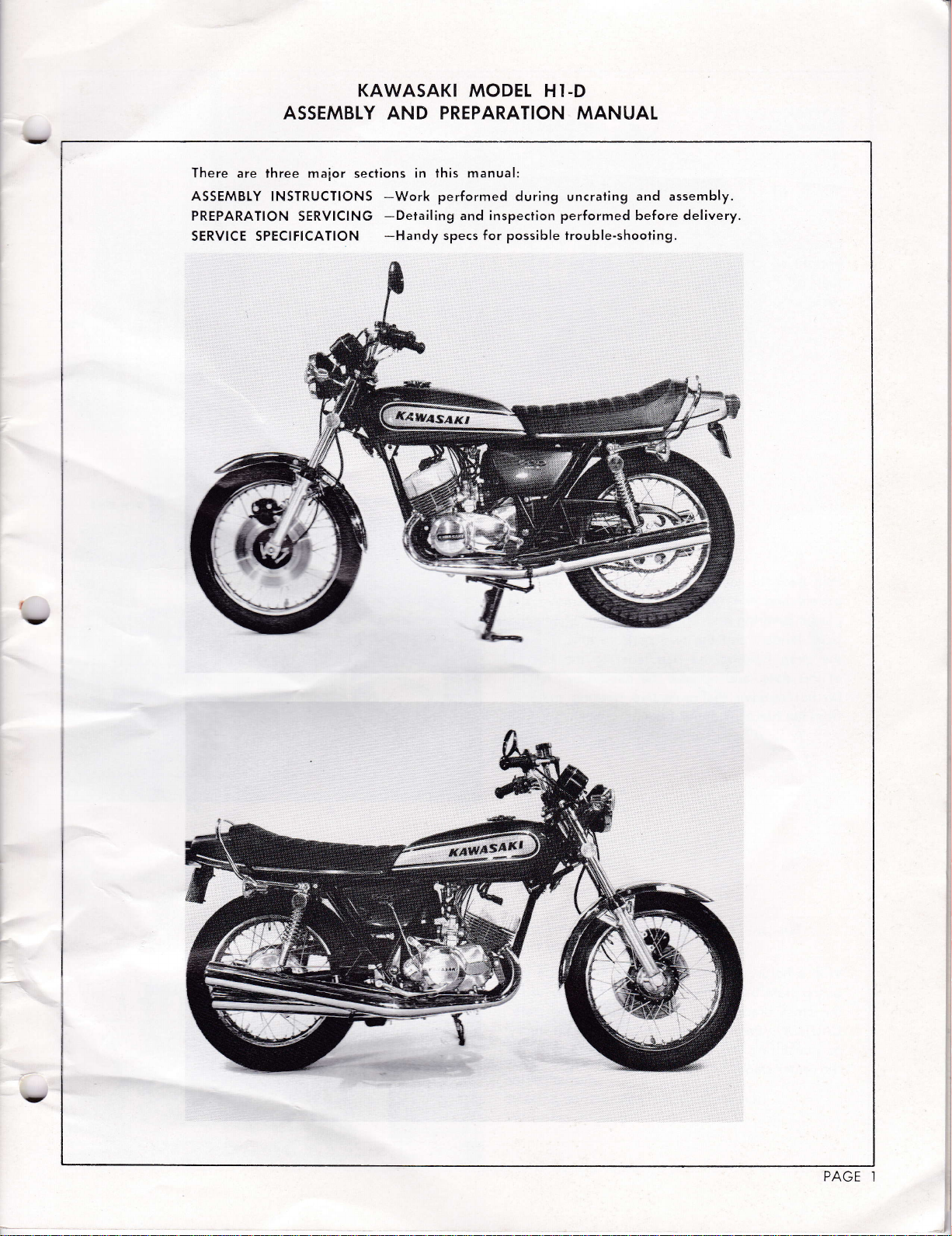
KAWASAKI MODEL
ASSEMBLY
There
are ihree maior
ASSEMBTY INSTRIJCTIONS
PREPARATION
SERVICE SPECIFICATION
SERVICING
seclions
AND
PREPARATION MANUAT
in this manual:
-Work
-Detailing
-Handy
performed during
specs for
and inspection
possible
HI.D
uncrating
performed
trou ble-shooting.
and assembly.
before
delivery.
PAGE
I
Page 3
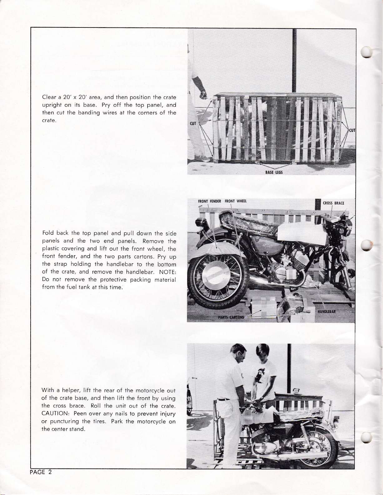
Clear a 20' x 20'area,
cut
on
the
its
base. Pry
banding
upright
then
crate.
and then
off
wires
at the corners
posilion
The crate
the Iop panel,
of
%
'#
and
the
BÂSE I.EGS
Fold
back the
panels
plastic
and The
covering
front fender,
the
strap holding
the
of
Do
f rom the f
crate,
not
remove the protective
uel Tank
top panel
Two
and
and the
end
lift
two
and pull
panels.
Ihe front
out
parts
the handlebar
and remove the
at this time.
down
Remove
wheel, the
côrtons.
to
the
handlebar.
packing
The
side
ihe
Pry up
bottorn
NOTE:
maierial
FRONT
Ë€
W}IEEI.
Ë
(Ross
lE
§,'
:l i
BRÂ(E
..:15
With
a helper, lift
the
of
crate base, and then lift
the cross
CAUTION: Peen
puncturing
or
Ihe center stand.
brace.
the tires.
the rear
Roll
over any nails to
of the moTorcycle
the front
the
uniT
ouf of
Park the moïorcycle
by
The
prevent
out
using
craTe.
iniury
on
**,
,§
u3"
t,É
Page 4
É\
!-t
'.:::' ':::l
§
1ÿ
-/
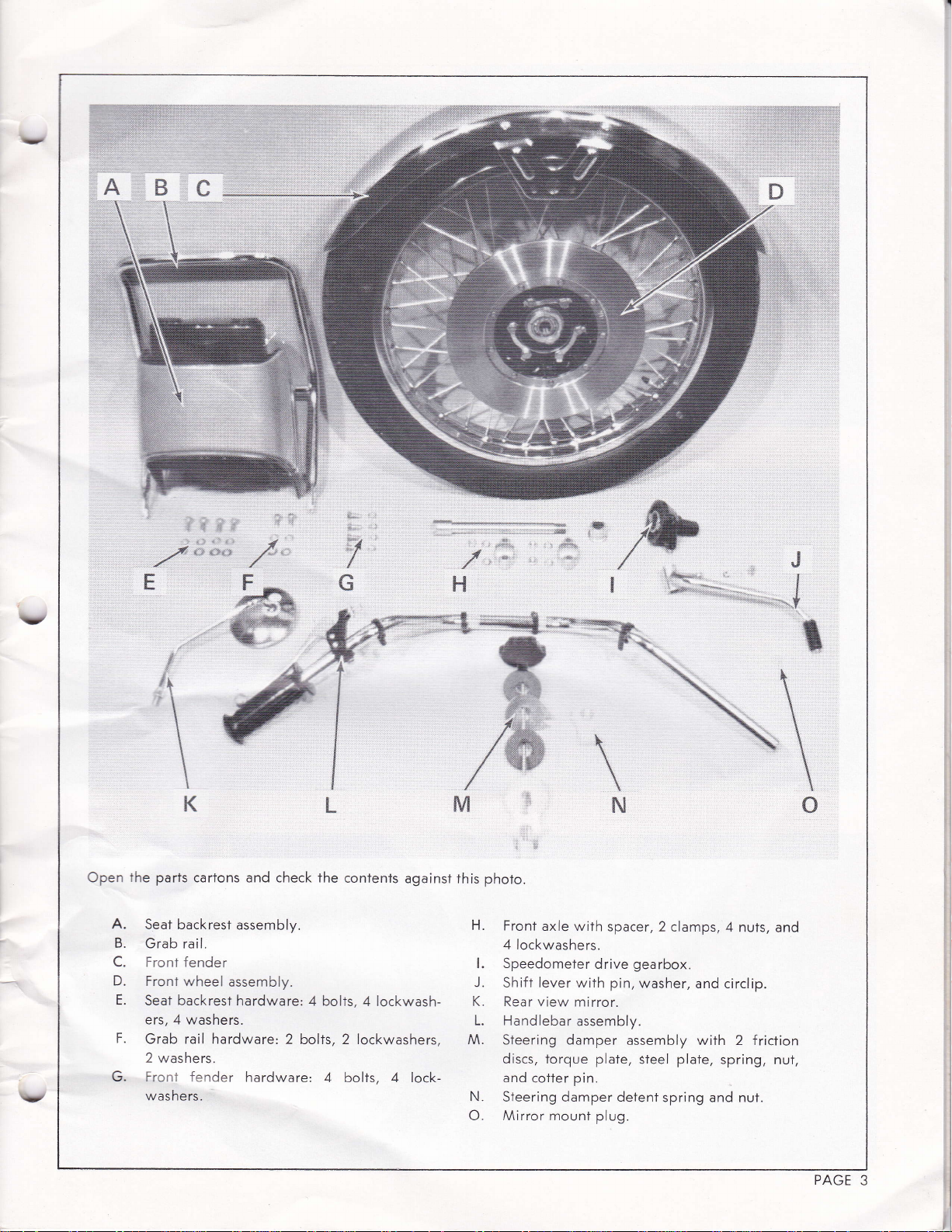
Open
A.
B.
C.
D.
E.
F.
G. Front
É
§:
l.
Êl
1
\
I
t
\
\
K
the parts
Seat backrest
Grab rail.
Front fender
Froni wheel
Seat backrest
ers, 4 washers.
Grab rail hardware:
2 washers.
washers.
carTons and check the
assembly.
ôssembly.
hardware: 4 bolts,
fender
§
§*
\J
,*
re !&
w
§=
''F:
i
I
t
I
I
t
I
I
I
I
I
I
i
I
Ê*
2 bolts, 2 lockwashers,
hardware'
4 bolts, 4 lock-
conïents
4 lockwash-
"...,'",,."-."#..t
;_----*
against
â
this
-.-.----._"&
"*
*Ër
ü
*
tmhffi
§
\
nt
rLt
phoio.
H.
Front
axle with
4lockwashers.
l. Speedometer
J.
Shift lever with pin,
K. Rear view
L. Handlebar
M.
Steering damper
discs,
torque
and
cotter
N.
STeering damper detent
O. Mirror mount plug.
spacer, 2
drive
mirror.
assembly.
plate,
pin.
clamps, 4
gearbox.
washer,
assembly with 2 friction
plate,
steel
spring and nut.
nuts,
and circlip.
spring,
and
nut,
t
m
rt
PAGE
3
Page 5
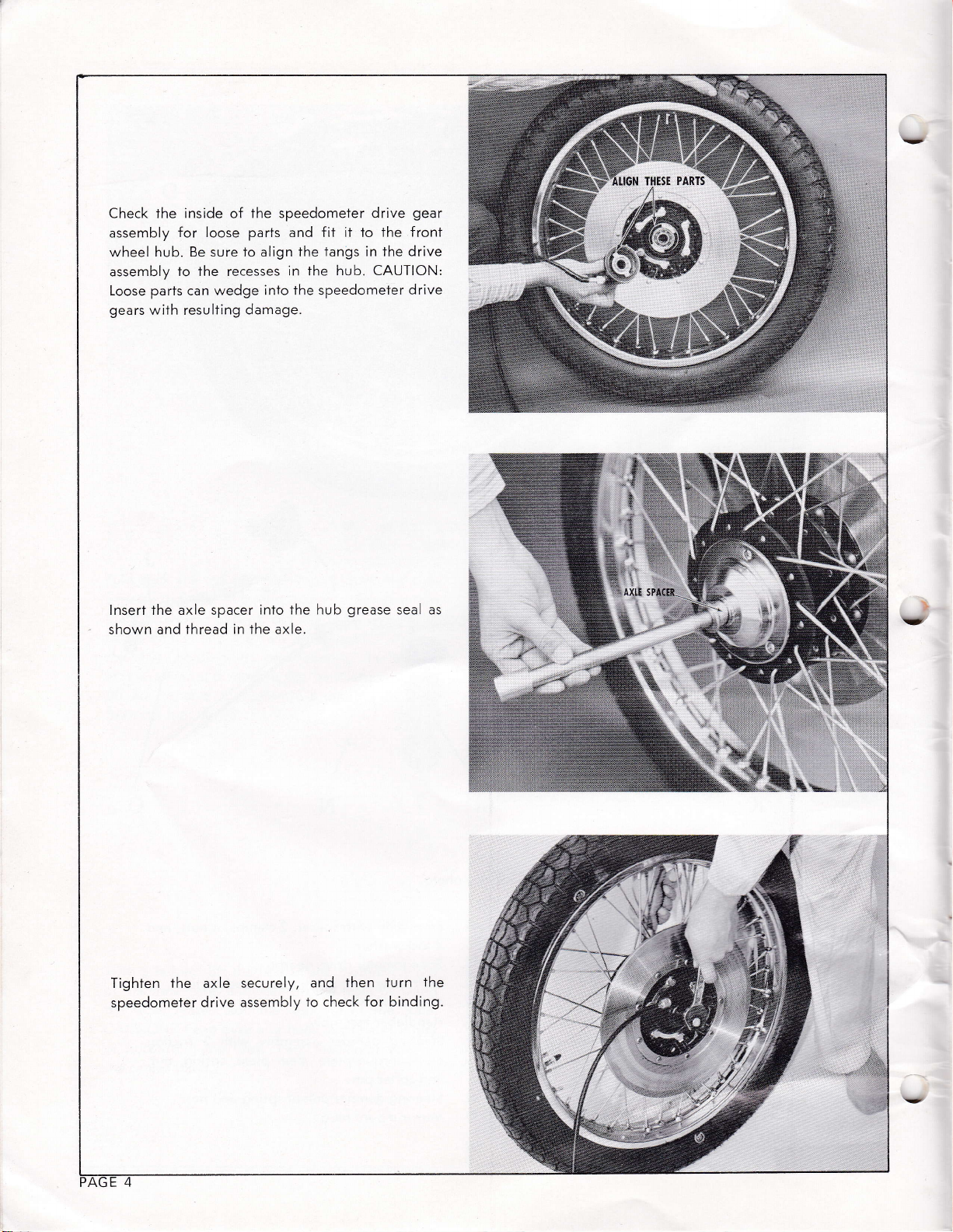
the inside
Check
assembly
hub. Be sure
wheel
assembly
parts
Loose
gears
wilh resulting
the speedometer
of
for loose
parts
to
align
to the recesses
can
wedge
into the speedometer
damage.
fit it to the
and
tangs in
the
in
the
gear
drive
front
drive
the
hub. CAUTION:
drive
THESE PARTS
lnsert the axle spacer
shown and
thread in the axle.
inio the hub
Tighten rhe axle securely,
speedometer
drive assembly
grease
then turn
and
to check
for
seaL as
the
binding.
!&
'j;
Page 6
Page 7
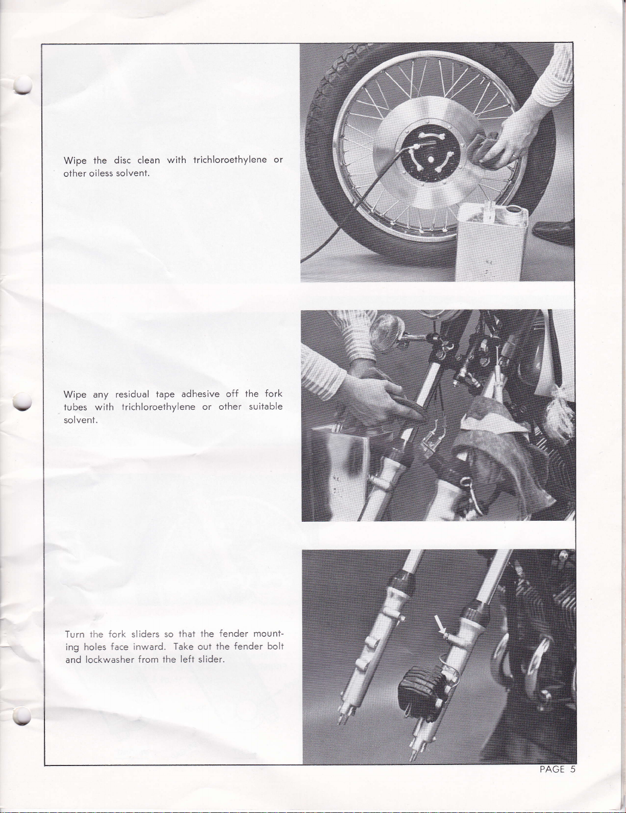
Mount the front
bolts
fender
brake
and the fork
bend
tion,
squeal.
lockwashers,
and
toward
hose
bracket between
sliders,
the hydraulic
it
or
may cause
fender
with four
with the
the front.
brake
Be sure
as shown. CAUTION:
pipe
the disc
14 mm
short end
of the
to mount
the fender
during
brake linings to
this
brace
Do
opera-
long
the
not
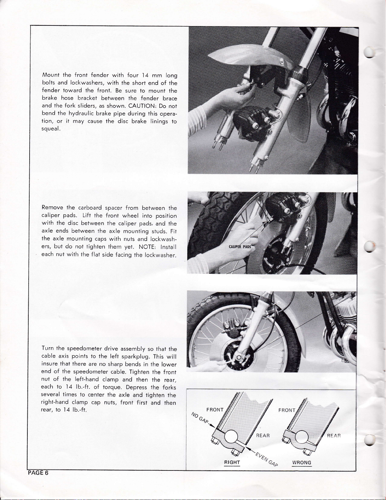
Remove
caliper pads.
with The
axle
the
ers,
each nuT
Turn
cable
insure
end
nut
each to
several times
right-hand
rear, to
the
disc
ends
between the
axle mounting
but do not
with
the speedometer
axis points
lhat there
of the
speedometer
of the left-hand
l4 lb.-ft.
clamp
l4 lb.-ft.
carboard
Lift
between the
the f lat
spacer from
the front
caps
tighten them
side facing
drive
to
the left
are no
clamp
of torque.
to
center
cap
nuts, front
the
wheel into position
caliper pads,
axle
mounting
with nuts
sharp
cable. Tighten
and lockwash-
yet.
NOTE:
the lockwasher.
assembly
sparkplug.
bends in
and then
Depress ihe
axle
and tighten
first
between
and the
studs. Fit
lnstall
so that the
This
the lower
the front
the
forks
and then
the
paosT#,1
will
rear,
the
F RONT
WRONG
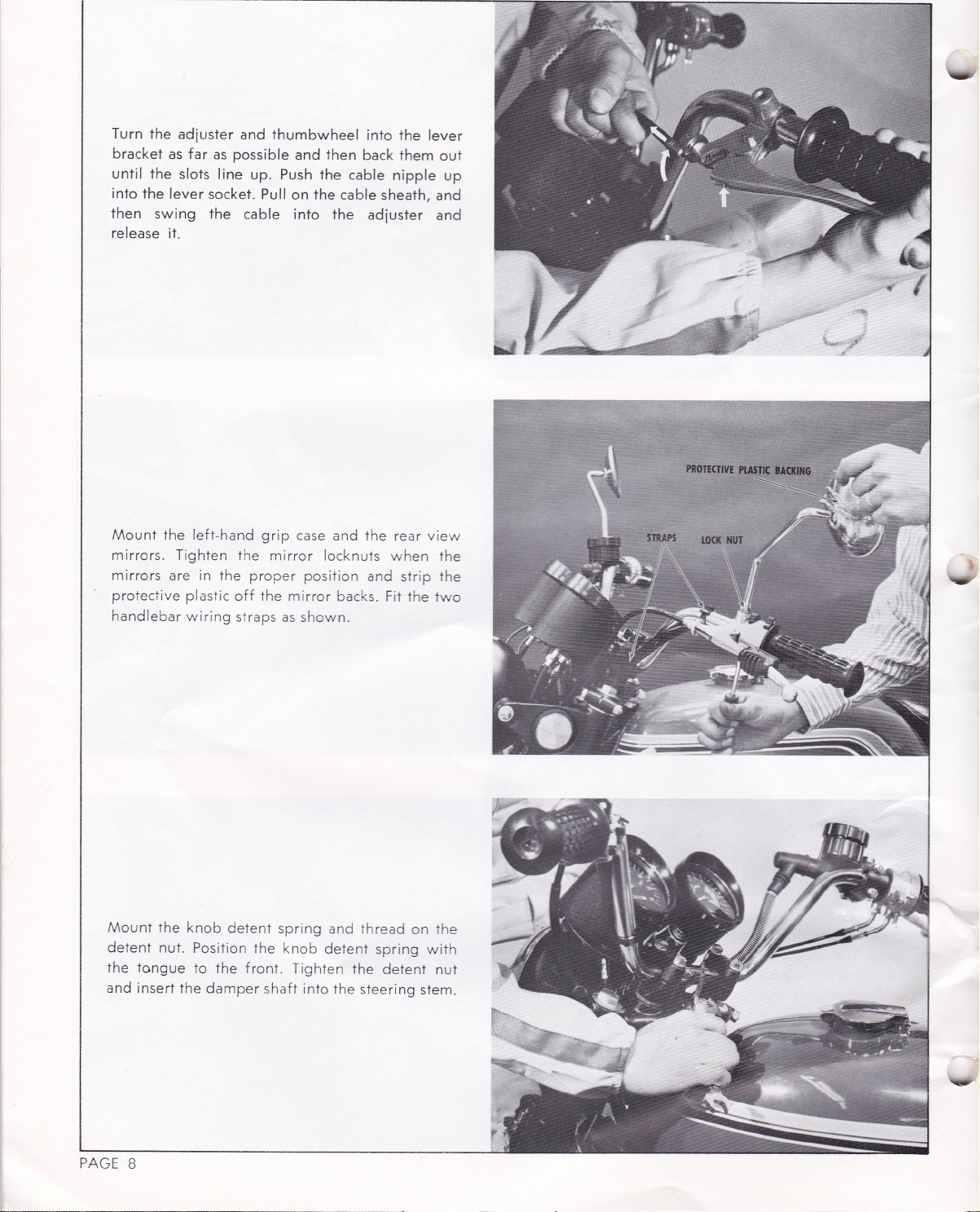
Page 8
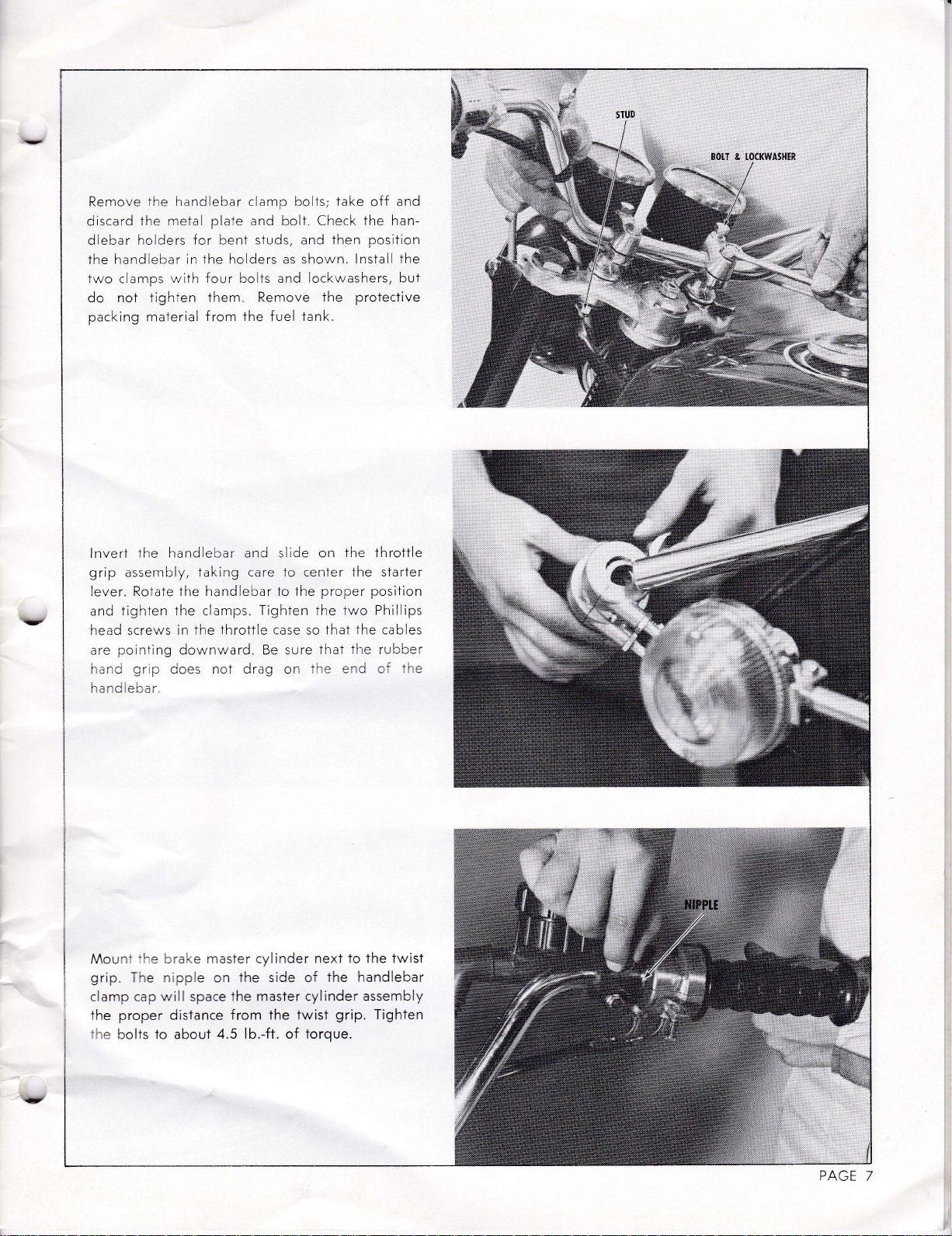
Remove
discard
dlebar holders
the
fwo clamps
do not lighten
packing material f rom
the handiebar clamp bolls; take
for
plate
beni
ihe metal
handlebar in the holders as
with four bolts and
them. Remove the
and bolt. Check
studs, and then
shown. lnstall the
lockwashers, but
the fuel tank.
and
off
the han-
position
prolective
lnverT
grip
lever.
and
head
are
i-.r-J
the hand
assembiy,
Rotale the handlebar io
tighten Ihe clamps.
screws
poiniing
gr p
ebar
laking care Io center the slarter
throttle
in the
downward. Be sure
does noT draq
i'ai'd e::a:
Mounl
grip.
clamp cap will space
Ihe
:he
the
The nipple on the side of
proper
bolts to aboul
môsTer cylinder
brake
distance
from
4.5 lb.-ft. of torque.
and siide on
the proper position
Tighten Ihe two Phillips
case
on
lhe master cylinder ôssembly
twist
the
the throttle
The
Ihat
so
thaT
ihe
next to the twist
The handlebar
ir.e
=-:
grip.
cab es
rubber
:t
Tighten
-'=
PAGE
7
Page 9
Page 10

Sl:ci tne steering
::;:re rsla
qreâse',',,
or
ar on.
th
an
eln/ ene, to insure
Ihese
assembly inslruclions
steering diff iculties.
damper parts,
CAUTION:
less
oi
solvent, such
smooTh damper
exactly
as shown here,
Clean
off any
trichloro,
as
action.
to prevent
oii
Fo low
TONGUE
PI.ATE
The
upper tongue
bridge
the
tongue
with
at
previous
plaie
spring,
the safeiy
i: rc..lnt
the factory.
cofler
the passenger
plate
sfep, taking
with
the frame
the
onto
damper shaft. Finally, insert
pin
and split the ends.
lnslall
upper shock mount nuts
sloite;.-C:
..Ii-:'
o--:'
+l-o
'
turn
::l',n,asher
-
-
, J I
^-.
.=
g
signal r'-rouni
:::-'ely. After tightening
:
: .'
-
ot
t
and
rhe grac
'l-
'
-:ce-
: C
"ru]ku,
washer
)-
-.
'i'JiS.
is
bolted Io
the fork
the paris
care 1o engage the
stud. Screw the nut,
grab
rail,
loosen
on both sides.
rail tubes
sL::L
,,
Ë-
lnser- : .tr
on each side a.:
Ihese
under the
^^o-'-:
:
-:
:c
lower
shown
Slip the
so
=
-
-r
..,
-
9-':.
:3-'e.
the
^h:+
in
Æ'
,
{-,,-(^
j,o*u*
NUT
PTATE
it st*;Jt{î
.,.:
L
a
t§tiT
&.
=
â
6ir§Ë
,têû !.ü§
-
.
''.;
i§ S.i
PAGE
9
Page 11

Position the
grab
rail and
each with
wires
a
by color code:
BlackiYellow
RediWhite Io
Blue,rRed To Blue
seat backresT assembly
fasten
washer and
place
in
it
Iockwasher. Connecl Ihe
to
Blackr'Yellow
Red
with four bolts,
under
the
.
;*#"q:,a
ït::éili:i:i::rl
i$EËer:i::.:
"*"6$tr
T:::ï:iï3:3§@
J
=:.:::::{::::ii:::,ai.:i
*i'.:.;::*.:,:.:::',',.,.:r..1
rq
hJ
-
Pry
off
washer
.Tighten
bolt.
the shift
Slide
the
hole
then insert
and
lnstall
the E-clip
from
the
the
shift sha{t clamp bolt and footrest
lever
in the shift lever and
the washer and
and
pivot
onto
the
then
shaft.
the
clevis
E-clip.
remove Ihe thrust
Grease
pivot
the turnbuckle,
pin f
the
shaft.
Line up
shaft.
rom behind.
fOOTRTSI
n*t.*l
BOIT
,: ::::
(tlvt§
ffiffi
Ptlr
PAGE
I
O
Page 12

lnstall
the thrusf
shaft. Adiust
has
equal clearance
the iurnbuckle
upshift/downshift
after adiustment.
washer
and E-clip
so that the
wilh the footrest
sirokes.
Tighten
the
on
pivot
shift Iever
bar
on
full
the locknuts
&&ËTy,'1,1
PAGE
i ]
Page 13

PREPARATION SERVICING
FILLING
Remove the battery
from the moTorcycle. Be
hose has been
the battery to the
Fill
lyte fluid, al a
the battery stand
drops below
electrolyte
before chargi
cover, and
sure that the battery
cut
the rubber
or
top Ievel with
temperature of 85o
2
for
hours.
the upper
line, top off
ng.
take rhe
band removed.
lf the
baTtery
fresh electro-
less. Let
F or
fluid level
with more
vent
CHARGING
To
avoid battery
Connect the battery
black Io
charge
l5 to
temperôture rises to
level drops, fill with
INSTATLATION
Wash off
sure
and
from
insulation
position halfway
to
final
tunity
Tact
around
the
THE VENT
over
frame
between
tube.
-)
ôt a rate
20 hours.
the battery
that
protect the battery.
the fuse
(-)
the
position. Make
for the battery
the battery
wiih
the end of
clamp
side
The
cross
the engine
damage,
to the battery
greater
Discontinue charging
any spilled
to the
position.
in
boot
and
post, as shown. Slide
the battery and secure
screw.
and
TUBE.
Route
panel
tube, inboard
remove all
charger
I I 5 " F. lf The elecTrolyte
disrilled water only.
acid
mat
(*)
then connect
sure That
post
box.
TAKE
screw
cases and
leads
posts. CAUTION: Do not
than I amp. Charge
f
with
position
in
is
Connect
batlery
the
SIide
the battery
there
leads
or
Place the battery
CARE NOT
vent tube
the
bracket,
the chain
of
the caps.
of
(red
water, Be
resh
to accept
the white
posl.
Push
battery
black
the
is no oppor-
to make
TO PINCH
forward,
behind
guard
the swing arm
to
for
if
the
lead
the
inlo
lead
inlo
con-
mat
it with
the
and
L,
,.",q,-
oi/
./
,,/
,,/
t/
REMoVE
AI.I CAPS FOR
§*'*
(HÀRGIII§
-
-i
& AFTER
CHARGING
---*
==æ\g
BATIER'
/&;
..,/
-=il
a';
ryra,
ê5
@
ri
§ll
==I
;
PAGE 12
Page 14

Remove
oil
remove the
40, 20W-50,
or
marked
threaded into
in
the
drain
from
the transmission.
{iller
oil
or
SE until the level is
on the level
the
place.
Quantity:
plug
and drain the preservative
Replace
cap
and
l0W-50
rnotor
between the
gauge
côse. Make sure the
qt.,
1.3
fill
'l.2
the
wiTh
oil
when
Iiter
or
plug,
drain
SAE l0-\/-
marked
SD
two lines
the cap is
O-ring is
42 {1.
oz.
-
{/
Renrove ïhe
qua1it,,r
NESS
the
oil
CAUTION: The
-lh--
oiastic vent
r^,s-
-i-:
s::' 3:
3:::'Ëe
--:
' et ban
-:-'en
:' :'.is
tcr
clogging
:f
=:.
+-.
ê-
).,-,'.-'
::osiTicn
oil lank cap
brand
THE
OF
tank
cap
[-^e
rcriec' so lhaT it w,i ] n:-
:
oll
jo
the
bolt.
altogether,
-
r-'t^e3:
-
--
:c
c
eeC a r o-- ct
:nes.
i. re
'
are
'.i-a
preseni
or
:,:_-.'',
bubb es
for
blockage
fili
anC
2'sli'oke
of
TANK
OIL
is rrr place
O-ring
melal
oi
from
iube
-r
-':
and the
,,"'''r
'
lank
hose
bolt. After twc
CAUTION:
check
crl
CHECK. THE
oii
BANJO
ian[
cap
the Tcl
--
i-:
: tr:ta'-.
of any air
minutes
lf the
the
oll
hcse
for
ai'-3 a-i e-
,l
=
--:
--.'-'a.
WLe:
î e::
=.-'
'is
'te
-:
: :
e, :
:.Ê
?x'.._Si d_e: i-:-:-Cte,
--:
loose
-
connect
rr-.e:s,.e
:
or^s
the Iank
BOLT Make
with a
TIGHT-
sure
cefcre nstaliing.
is
i-rci venTeC.
c:'-= i lanfr
::: r--
:
--::
by ioosening
of oil f low,
flcw
oil
tank
pinching.
::anic
:::eJ
-
-
-:- -':-'-
banio bolt
bolts,
at 1500_
.
=
^-c
,--:d
is
-:-
slow
Also
StarT
a:-a'
:r'd
,,
:..rr-
-.
Of if
:nes,
check
:-.
:
PAGE
13
Page 15

:ct
\I>
ryi,'.Ë:::::u::&,:
i,1:.ît:ffi
-.11§i,i:r:J::.:'::
.
;::qit.,::l:t:::,j:l
.,i:i
:
j,:::.::
::i::ti.,::i:
ï;:r:i:
;U::.,:tia.,r
r*
:;;::,::.::
Tei:::a..,-::
-r,r'ii.;,:..r':.
fh*
ffiw
ffi
#Ë,
re
%**
W
l;;
'
i.-'
*
W
Ë,r
"i"
,a
liii,.ÿ@
ffi
#a#*
tr
§
Ë
§
Ë
PAGE ]
SETTING
Remove The
the
with the magnet
ups.
ihe pick-up
is incorrecl,
4
THE AIR GAP
tab
on
There
ignition cover. Turn the engine
the signal
should
and
fully loosen
generator
in Ihe center of one of
gap
be a
the Iab
on
the
rolor
of 0.025
the rolor.
screws
two
in. between
is
allgned
the
lf the
"A"
until
pick-
gap
and
pick-up
the
adlust
securely and repeat
pick-ups. CAUTION:
lwo
with
ups
the
screws
pick-ups, or
the
screwdriver
a
are completely
they
hand.
by
procedure on
the
Do
or any
loose
mav break.
Tighten
pry
noT
other
before
the screws
the other
the
on
Be
tool.
adiusting
pick-
sure
Page 16

ffi§
ml:ôr!§§il:
,r.S#&'
I
,
STATIC IGNITION TIMING
Remove the
sparkplug and
fit
a
dial
left cylinder. Turn the crankshaft
cenier and then rotate
gôuge
shows that the
it
clockwise
piston is 2.94mm BTDC.
gauge
to
the
to top dead
the
until
dial
The pointer
on the
accordingly.
place
rotor. lf it does noÎ,
the
sparkplug.
should now align
Take
out
the
dial
with the
bend
indicator and re-
"1"
mark
the pointer
PAGE
15
Page 17

L
§t
l
3
*kËâ&
#m
§*rt
::: il
qr
ffi*i
hiffi
Emru
re
I
MX
æH*; {
Turn
the
crankshaft
"S" (static)
The
up with
rotor
tab
up for rhe left-hand
not, loosen
pick-up
after
accordingly.
adiustment.
pointer.
the
should
The two
mark
align wilh the
in
the
nearest the
The
cylinder,
screws
Tighten
Turn
the crankshaft
direciion
"1"
Irailing
mark
as
shown. If it
"8"
and adiust
the
screws securely
& æ";T
&æ
shown
edge of the
on the
until
mark lines
pick-
does
the
until the
poinler
on
should align with
right-hand
the
on lhe rotor,
pick-up.
aligns with
the
rotor. The
pick-up.
cylinder. lf
Using the
do
ræçé
r i'§
ffi§
,-E
tr
âg
ffi
4t!ôqt!*".,.i*É!
,:;;:riffi
"S"
the
Trailing edge
the mark
the
same for the center cylinder
mark nearest the
of
the
on
.
it does not
"S"
mark nearest the
the
pick-up
align, adiusf
iRrü;l
"R"
rotor tab
for
the
"C"
-'
ttl-
PAGE
16
Page 18

PAPER CIIP
r
<-
\
'I&iF§g
§
h.
DYNAMIC IGNITION
Connect a stroboscopic
hand
sparkplug
tain
light,
the
steady
"1"
speed of 4000
to see
check
mark
on
TIMING
wire. Start
thai ihe
the rotor. lf
Timing
Iight
the engine and
rpm. Using
pointer
it does not align,
to
the
môin-
the timing
aligns
left-
with
loosen the two screws
up. After adiustment,
RepeaT this
hand
marks,
procedure
cylinder
respectively.
iighten the screws securely.
pick-ups,
"8"
and adiusf the
pick-
for the center and right-
using the
"C"
and
"R"
PAG E
17
Page 19

STARTER CABTE
Loosen
the
same lo the throttle
the locknut
starter cable has
ADJUSTMENT
and turn the
least
at
cable.
7+"
adiuster in until
of slack.
Do
the
Tug
which
is
slightly, causing
retor.
côp, loosen the locknut,
Tighten
carburetor is
necessary to
ment.
CARBURETOR
For smooth,
buretors must all have the same slide
any Ihrottle
screws completely so That the throttle valves resl
on
throttle
no1 holding the
the
tle
ômount of slack: 1 16' . Correcl
cable by loosening Ihe locknut
cable adiuster. When ali three cables have
slack,
the Three slides will be
position
the
on
no slack, the
starter cables 1o check for free
should
To
adiust cable slack,
the locknut
reliable
opening.
the
bottom
to make sure it
rod
posilion:
same
lo
cables
tighten
f
rorn
make sure
fully closed to wide
be 7e" in each cable. NOTE:
starler
plunger
mixlures
rich
and lurn
afler adlusting.
will
f
pull
rom
be held
thal
up Ihe
the adiuster.
NOTE, The
removed here for clarity;
remove the
SYNCHRONIZATION
carburetor for
pei'formance,
the three car-
position
Turn in
the carburetor veniuris; lift
of
has some
slide open. The
fully
closed" Tug
each cable has the
throttle
3
all
play
slides are now in
on Ihe
any lighI
and lurning the
Iocknuts. After this
the
parallel
operation,
aT any throTtle
open.
play,
lf there
open
carbu-
rubber
it is not
adiust-
stop
each
and is
throt-
same
loose
or
,'l6"
I
---r
l
ôt
§
â!
'1
ii
--:aT'I:T!t
-l::;i.:,i:'*1.=
S(RIW
:=
=Ë
PAGE 18
Page 20

Turn in each air screw until
it
and then back
warm it up
and
ihe throttle
1300-1500 rpm
of
over
is balanced among
the exhaust,
the screw
out
screw on a
balanced,
stop screw and
ing.
stop screws evenly
the mufflers
turn
on a
"strong"
wrap electrical
11/t turns. Start
ouI
for
minute or lwo;
a
is
obtained.
to
if the exhaust
see
three cylinders.
the
ihe throttle stop
"weak"
cylinder.
tape around
cable adiusTer
cylinder;
it bottoms
the engine
then back out
until a
When the
to
stable idle
your
Hold
To balance
screws
turn in the
The throttle
prevent loosen-
lightly,
hands
pressure
back
-
idle is
STOP SfiEW
.*&
§
æbf,THROTITE
Ç
Finally, lengthen
twistgrip so
play
1
/8"
cable. lnstall
er
check the
clamps.
OIL
-s.e:i
':
',
,-'.-- 3îc
.-
:
':-l
in the throttle.
tightness
PUMP
the
-'=
-.-,-relors.
-
r-
-'
: ::
that there is
the
carburetor rubber
of
ADJUSTMENT
pump
oil
^ - ^-
i Jtrvÿil
__ê
iuTn
-':
-
adiustmeni only
The mark on
.,i+
mô larror nnq rinn
-
the cable adlusier
same time
-i'i'
-
the
cable adiuster on
approximalely
Do
the same
1/16"-
to the start-
caps, and
the carburetor mounting
after adiust-
T
-
oil
_
^::_
:--:-
--=
-1i
pump
mi': :
"=
-:-
The
-'=
i
the
.,æ
_È:
--=
3'ê-
PAGE 19
Page 21

CLUTCH ADJUSTMENT
Remove the
the
of
approximaTely
lever
under The
release screw and then turn the screw clockwise
until
Hold The screw in llris
the locknut. Check
sprocket cover and
clutch
release lever, which
8 o'clock, as shown. Correct
position
you
by turning the clutch
gas tank.
slari
iust
Loosen
to feel
position
tightness
the
check the
position
should be at
the
cable ad
locknut
the
clutch spring tension.
juster
on
the
while tightening
the
of
sprocket
nut, making sure the washer is bent, and then
replace the sprocket
cover.
THUIYIBWHEEI\
Turn
lhe clutch
obtain arzâ"
spring tension,
Check
the fluid level
reservoir with
possible.
inside wall
following
Atlas
Extra Heavy Duiy
Shell
Super
Texaco
Wagner Lockheed
Check to be sure that the master cylinder
bolt is tightened to 20 lb.-ft.
cable adiuster
gap
and then lighten the thumbwheel.
the
you
when
in fhe
reservoir held
lf the fluid level
of The
recommended brake f luid
Super Heavy Duty
reservoir,
Heavy Duty
Heavy Duty
ihe
orr
jusl
sIarT to feel
brake masfer
nearly
as
below
fill
it with
the
is
of torque.
handlebar to
cylinder
line
one of ïhe
brands:
ciutch
level
on Ihe
banio
as
PAGE
20
Page 22

Check to
fitting
way
The
brakelight
lb.-ft.
of
Check
to
tightened
bleeder
lb.-ft.
valve
of torque.
be sure both
are tightened to
switch should
torque
be
sure that ihese
to
abour
should
banio
bolls
20
be tightened
hydraulic
12.5
Ib.-fr.
be tightened
the
on
lb.-ft.
of
Torque.
fittings
of torque.
io
about
three-
to l3
ry
are
The
6.5
ryffi
Remove
r::,i.
side
until the
slack
the
after
:
=-c
Ihe
t
on ihe
the
Loosen
of the
on the
sprockets.
adiustmenf.
is
'
scl'ocket
crârr' aCluster
the
swing
drive
lower
replaced.
swing
cotter pin
chain
arm. Turn
chain
has
run
Tighten
CAUTION:
NOTE:
alignment,
posilioned
are
arm taos.
loosen
and
adiuster locknuls
less than
iust
of chain,
the locknuls
Make
the
the
adiuster
midway
and
sure the
To insure proper
make
sure ïhe marks
at equal
rear
on either
bolts
one inch
between
axle nuts
coiter
wheel
divisions
axle
of
on
CHÂIII ÀDJUSTER'IiÂRI§
ftê-
Ëxs
&P
Page 23

The
rear brake
free movement.
of
accordingly.
posilion.
pedal
Adiust
should have about
lf it doesn't, Turn the
both rear shocks
to
the softest
inch
one
adiusfer
Turn the main
f
ront and rear brakes
light
switch does
light should turn
brake
pedal
travels
switch by
adiusting
ment.
switch on, and then operate ihe
1/2"
loosening the
nut. Tighten lhe locknut
individually.
not
require adiustment.
when the
on
3/t".
lo
Adiusl the
locknut and turning the
The f ront brake
The
brake
rear
lamp
brake
afïer adlust-
ÀllJllSüt {Rear
IIOP
lrofre}
TIGHT
ÀDJUSTIN§
IIUI
To
before
the
PAGE
prevent f lat-spotling, the
crôting. Reduce
front
tire, and
22
the pressures to: 26 psi in
psi
3l
in the
tires are overinf
rear.
lated
Page 24

E^
J6S
3ê
Èâ>>
*i;NN
EÉ
E
I
9-
3r-
!;
llun
uortru0l
\1
T
tsJ
F
!
OF
-
rr
.;E
g
z
o
6>>
:6-=
=E
3
>
"->
EiâNN
g
c-3
P
-3.5
I
r-
o
!
G
É
I
3
l------E
sE
:o
I
À
t
&
ts
)
I
o
0
.9
.:
ï
1
ô
ï
à
ï
6
!
I
o o
I
II
o
rtr
=
o
E
L
F
Â
L
o
fl
s
q
û
B=
: !d! i>
q6*r
iiÈ E
>
-5
;È
P>
^cN
T,E
a)
,-l
q6
10 ÈN
si
E i
o-
§
E8
ôc
È
ËERS
I è>>
s c-S
JÉ
=ê
Ë
I
PAGE
23
Page 25

-
:,
PAGE
24
Page 26

KAWASAKI
PRE-SALE
CHECK THESE ITEMS BEFORE DETIVERY
MODET HI.D
SERVICE
ITEM DESCRIPTION
l
Clutch Lever Pivot Nu1
lnstrument
2
J
Brake Bleeder Valve
4
Brake Lever Pivot
Exhaust FIange
5
Tank
Oil
6
7
Lever Bracket Clamp
Seat Hinqe
I
9
12
r3
16
17
t8
a/
37
38
39
j0
Seat
Rear Fender
Tail Lamp
Side
Hydraulic
Carburetor
Shift Lever Bolt
Rear Brake Cam Lever Bolt
Seat
Front
Chain Adiuster Locknuts
Handlebar Clamp
Fronf Axle Clamp
Front Fender
Top
Rear
Brake Hose Bônio Bolts
Rear Turn
Brake
Caliper
Kickstarter Lever BolT
Passenger Peg
Lower
Eng ne
Lower
Top
Foorceg
Scr::<eI
C.
S ::s'and Mount Bolt
S..,.
Rear-Axle
r0
il
14
t5
t9
20
21
22
23
24
25
lo
v
27
1C)
29
30
3t
aa
35
36
Bolts
Latch Bolts
Cover
Backrest
Muff
Triple
Brake
Torque
Brackeï Bolts
Shock
^,roLnl
Tr ple
Sl-cck Mount Nuts
Bolts
n:er
-?ôrm
(4)
Nuts
Nuf
(6)
Nuts
(2)
Bolis
(4)
Bolts
(4)
(2)
Bolts
(5)
Bolts
(2)
Bolts
Pipe
Filtings
(2)
Manifold Nuts
(4)
Bolts
Ier
Mount Bolts
Bolts
Bolts
(2)
(4)
(4)
Mount Bolts
(2)
(2)
Bolts
(5)
Bolts
(.l2)
(3)
Nut
(3)
(2)
(2)
(2)
Clamp Bolts
Pedal Pivot
Signal Mount Nuts
Link Nuts
Nuts
À,ÀcL,r-rt
NuTs
Clamp
(2)
(6)
Nuts
Head
Nuts
Pivoi Nut
Nut
(3)
(6)
(2)
(4)
(2)
(2
TOOI S|ZE
Bmm
8mm
l0mm
l0mm
l0mm
l0mm
l0mm
l0mm
l0mm
l0mm
l0mn.r
l0mm
I0mm
I2mm
l3mm
l3mm
I3mm
l3mm
l3mm
l3mm
l3mm
l3mm
l3mm
l3mm
l4mm
l4mnr
l4mm
l4mm
I4mm
l4mm
l4mm
l Tmm
tr7mm
I7mm
17mm
l Tmm
l Tmm
l Tmm
24mm
27mm
REMARKS
lb.-f1.
6.5
lb.-ft.
4.5
lb.-ft.
12.5
lb.-ft.
l2
lb.-ft.
t 4
lb.-ft.
20
w/safety
clips
w/lockwashers
w/lockplates
lb.-ft.
l9
lb.-ft.
150
w,/cotter
Pin
55 lb.-ft.
!.'Craulic
,1;eering
Fuel
Steering
Caliper
r:,r
Center
SeaI
Chain
_ :
-':
Tire
Spoke N
Brake Light
Stem Bolt
Valve
Bearing Nut
Bolts
Bral,e Rod Link Pin
Sfand Pivot Joints
H nge
Guard Screws
--J-- c---
'
-El
l:3.-.--=
Pressr,r'e
ipples
Nut
(2)
Pins
J-tgvl 5 t.
-
(2)
="a..'
R:.-
(2)
^
Switch
(2)
l
27mm
27mm
30mm
42mm
l0mm
Allen Head
Cotter Pin
Washer &
CotTer Pin
Washer
SafeTy Clip
=2
=2
26
31
&
Phillips
Phillips
psi
psi
lb.-ft.
I3
Spanner
No
bind.
chain
Check
clearance
Check &
Do not
lype.
excessive
guard
to
Tighten
plôy
PAGE
25
Page 27

KAWASAKI
SERVICE
SPECIFICATIONS
MODEL
HI.D
V
Manufacture
Floai Level
Fuei Level
Main Jet
Needle
Jet & Primary Choke
Size
&
&
Type
Jet Needle & Clip
Pilot
Jet
Throttle
Air Screw
Air
lgnilion
lgni'ion
Valve Cutaway
(Turns
Gap
Timing
Tin"ing-
Sparkplug Type
Type
Position
Out)
Static
-
Dynar.
MikuniVM2SSC
+
(mm)
24.0
30.0
=92.5
+0-4
#5DJ
lmm
r
lmm
R
I
l9-4rh
#30
i
2,0
l)i
0.025"
2.94mm BIDC
c
23'
BTDC
NGK B 9HS
at
4000
RPM
PAGE
26
Sparkp ug
Front Fork
Front
Front Fork
Transmission
Transmission
Brake Fiuid
Fork
Gap
Oil
Oil
Oil Levei
Type
Quantity
OilType
Oil
Qpap11i1y
(from
Top)
0.040"
IOW
SAE
I 60cc
448mm
sAE t 0w-40, 20w-50,
l0-W50
I
200cc, 1 .3
Atlas
Shell Super Heavy Duty
Texaco
Wagner
SD or SE
qt.,
4211.
ExIra Heavy Duty
Heavy Duty
Super
Lockheed
Heavy
oz.
DuIy
Page 28

 Loading...