

Kawasaki E Series, E13, E12, E10, E20 External I/o Manual
...
Kawasaki Robot Controller
E Series
External I/O Manual
Kawasaki Heavy Industries, Ltd.
90204-1023DEF

E Series Controller
Kawasaki Robot External I/O Manual
PREF ACE
This manual describes external I/O signals for the Kawasaki Robot Controller E series.
This manual also explains procedures for connecting the controller and an external device.
For supplying primary source and operations of robot, see Operation Manual, a separate manual.
Please understand the contents of this manual thoroughly and perform operations carefully.
This manual supports the following controller models.
E10, E12, E13, E14, E20, E22, E23, E24, E73, E74, E94 (standard spec. for Japan)
E30, E32, E33, E34, E76, E77, E97 (standard spec. for North A merica)
E40, E42, E43, E44, E70, E71, E99 (standard spec. for Europe)
E25, E27 (explosion-proof spec. for Japan)
E35, E37 (explosion-proof spec. for North America)
[ NOTE ]
1. This manual does not constitute a guarantee of the s ystems in wh ich the robot is utiliz ed.
Accordingly , Kawasaki is not responsible for any accidents, damages, and/or problem s
relating to industrial property rights as a result of using the system.
2. It is recommended that all personnel assigned for activation, operation, teaching, maintenance
or inspection of the robot attend the necessary education/training course(s) prepared by
Kawasaki, before assuming their responsibilities.
3. Kawasaki reserves the right to change, revise, or update this manual without prior notice.
4. This manual may not, in whole or in part, be reprinted or copied without the prior wr itten
consent of Kawasaki.
5. Store this manual with care and keep it available for use at any time. If the robot is
reinstalled or moved to a different site or sold off to a different user, attach this manual to the
robot without fail. In the event the manual is lost or damaged severely, contact Kawasaki.
Copyright © 2012 Kawasaki Heavy Industries Ltd. All rights reserved.
1
E Series Controller
Kawasaki Robot External I/O Manual
SYMBOLS
The items that require special attention in this manual are des ignated with th e following sym bols.
Ensure proper and safe operation of the robot and prevent physical injury or property damage by
complying with the safety matters given in the boxes with these symbols.
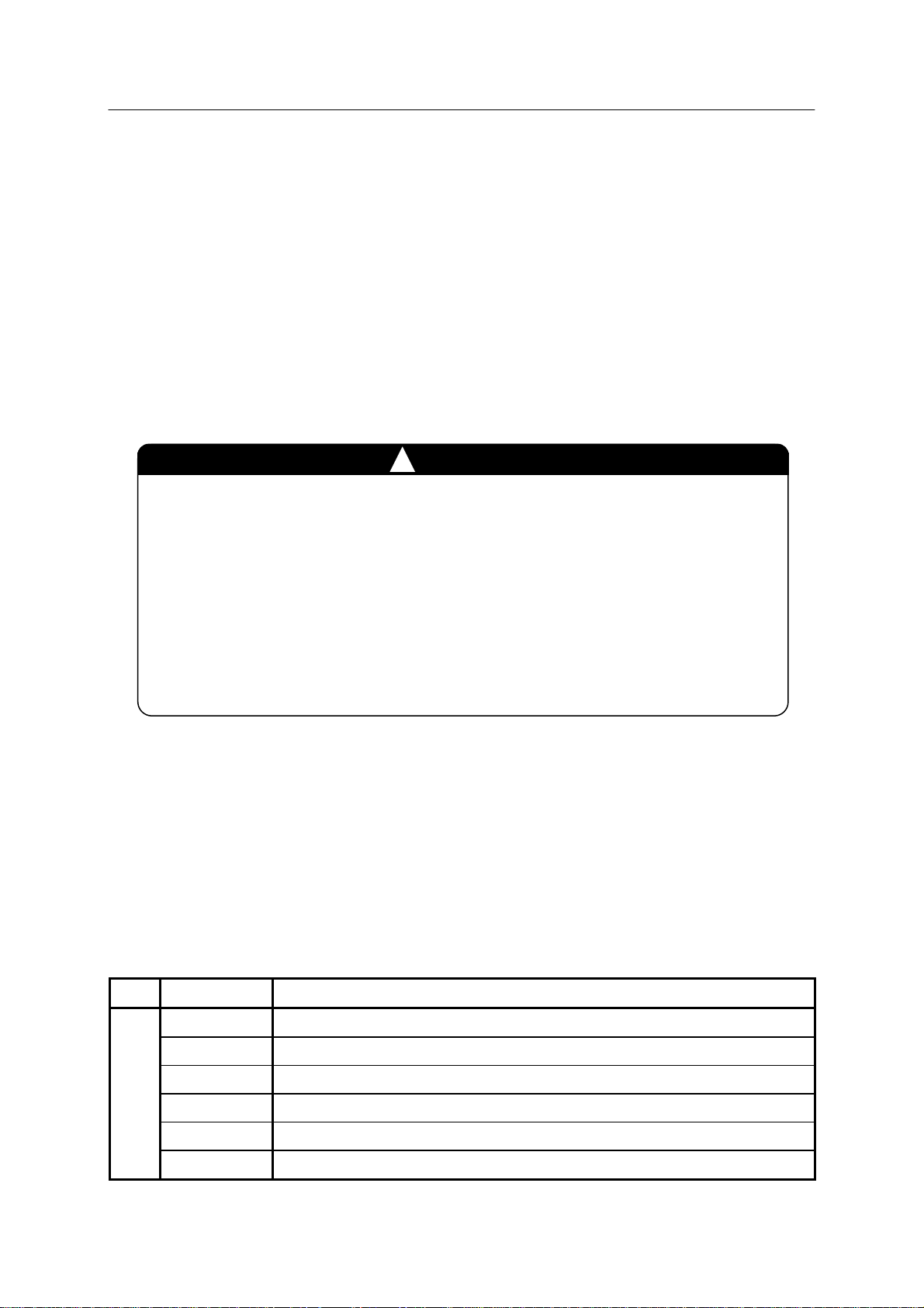
DANGER
Failure to comply with indicated matters can r esult in
imminent injury or death.
!
1. The accuracy and effectiveness of the diagrams, procedures, and detail
explanations given in this manual cannot be confirmed with absolute
certainty. Accordingly, it is necessary to g ive one’s fullest attention when
using this manual to perform any work. Should any unexplained
questions or problems arise, please contact Kawasaki.
2. Safety related contents described in this manual apply to each individual
work and not to all robot work. In order to perform every w ork in safety,
read and fully understand the safety manual, all pertinent laws, r egulations
and related materials as well as all the safety explanation described in each
chapter, and prepar e safety measur es suitable for actual work.
Failure to comply with indicated matters may possibly lead
to injury or death.
Failure to comply with indicated matters may lead to physical
injury and/or mechanical damage.
Denotes precautions regarding robot specification,
handling, teaching, operation and maintenance.
!
!
!
WARNING
CAUTION
[ NOTE ]
WARNING
2

E Series Controller
Kawasaki Robot External I/O Manual
INTRODUCTOR Y NOTES
1. HARDWARE KEYS AND SWITCHES (BUTTON)
E series controller provides hardware keys and switches on the operation panel and the teach
pendant for various kinds of operations. In this manual the names of the hardware keys and
switches are enclosed with a square as follows. The terms “key” or “switch” which should
follow the relevant names are sometimes omitted for simpler exp ression. When press ing two or
more keys at the same time, the keys are indicated by “+” as shown in the example below.
EXAMPLES
ENTER: expresses the hardware key “ENTER”.
TEACH/REPEAT: indicates the m ode switch “TEA CH/REPEAT” on the operation panel.
A+MENU: indicates pressing and holding down A then pressing MENU.
2. SOFTWARE KEYS AND SWITCHES
E series controller provides software keys and switches which appear on the screen of the teach
pendant for various kinds of operations depending on specifications and situations. In this
manual, the names of software keys and switches are enclosed by “< >” parentheses. The terms
“key” or “switch” which should follow the relevant names are sometimes omitted for simpler
expression.
EXAMPLES
<ENTER>: expresses an “ENTER” key that appears on the teach pendant screen.
<NEXT PAGE>: expresses a “NEXT PAGE” key on the teach pendant screen.
3. SELECTION ITEMS
Very often an item must be selected from a menu or pull-down menu on the teach pendant screen.
In this manual the names of these menu items are enclosed in brackets [XXX].
EXAMPLES
[Auxiliary Function]: Expresses the item “Auxiliary Function” in a menu. To select it, move the
cursor to the relevant item by the arrow keys, and press the key. For
detailed description, this procedure should be described every time, but
“select [XXX] item” will be used instead for simpler expression.
3

E Series Controller
Kawasaki Robot External I/O Manual
1.0 Types of External I/O Signal ·································································· 6
1.1 Hardware Dedicated Signals ·································································· 7
1.2 Software Dedicated Signals ··································································· 8
1.2.1 Software Dedicated Input Signals ···························································· 9
1.2.2 Software Dedicated Output Signals ························································· 12
1.3 General Purpose I/O Signals ·································································· 14
1.3.1 Types of General Purpose Signals ··························································· 14
1.3.2 I/O Timing of General Purpose Signals ····················································· 15
1.3.2.1 I/O Timing through Teaching ································································ 15
1.3.2.2 I/O Timing through AS Programming ······················································ 16
2.0 Requirements for Connecting External I/O Signals ······································· 19
CONTENTS
2.1 Hardware Dedicated Signals ································································· 19
2.1.1 External Control Power ON/OFF ···························································· 19
2.1.2 External Motor Power ON ···································································· 21
2.1.3 Safety Circuit OFF ············································································· 22
2.1.3.1 External Emergency Stop ····································································· 24
2.1.3.2 Safety Fence Input ············································································· 29
2.1.3.3 External Trigger Input ········································································· 30
2.1.4 External HOLD ················································································ 32
2.1.5 TEACH/REPEAT Output ···································································· 33
2.1.6 Error Occurrence Output ······································································ 33
2.2 General Purpose I/O Signals ·································································· 34
2.2.1 External Input Signals (External Robot) ················································ 34
2.2.2 External Output Signals (Robot External) ·············································· 36
3.0 Procedures for Connecting External I/O Signals ·········································· 39
3.1 Connecting Hardware Dedicated Signals ··················································· 40
3.2 Connecting General Purpose Signals ························································ 40
3.3 Connecting Expanded I/O Signals (Option) ················································ 40
Appendix 1.0 Procedure for Stopping Robot ····················································· A-1
Appendix 1.1 External Emergency Stop (Safety Circuit OFF) ································ A-1
Appendix 1.2 External HOLD ····································································· A-2
4

E Series Controller
Kawasaki Robot External I/O Manual
Appendix 2.0 External Program Selection Function ············································ A-3
Appendix 2.1 Using IF Instruction to Switch between Programs ····························· A-4
Appendix 2.2 Using RPS Function to Switch between Programs ····························· A-5
Appendix 2.3 Using JUMP Function to Switch between Programs ·························· A-7
Appendix 3.0 Output Function for Home Position Signal ····································· A-10
Appendix 4.0 Mutual Interlock···································································· A-11
Appendix 5.0 Output Timing of Clamp Signal (Handling Application) ···················· A-13
Appendix 6.0 Dedicated Signals Classified by Application ··································· A-15
Appendix 6.1 Handling Specification ···························································· A-15
Appendix 6.2 Spot Welding Specification for Pneumatic Gun ······························· A-18
Appendix 6.3 Arc Welding Specification ························································ A-26
Appendix 7.0 External I/O Signal Pin Assignment ············································ A-35
Appendix 7.1 1TW Board Pin Assignment ····················································· A-35
Appendix 7.2 Hardware Dedicated Signal Pin Assignment on 1TR Board ················ A-37
Appendix 8.0 General Purpose Signal Assignment List ······································· A-39
Appendix 9.0 Internal I/O Signal for RS03 (E70/E73/E76) ··································· A-41
Appendix 9.1 Outline of Internal I/O Signal Control ·········································· A-41
Appendix 9.2 Software Setting and Signal Allocation of Internal I/O for RS03 ··········· A-42
Appendix 9.3 1UU Board Setting ································································ A-43
Appendix 9.3.1 Jumper ··············································································· A-43
Appendix 9.3.2 Connector ··········································································· A-43
Appendix 9.4 Error Code ·········································································· A-44
5
E Series Controller 1. Types of External I/O Signal
[
]
Kawasaki Robot External I/O Manual
1.0 TYPES OF EXTERNAL I/O SIGNAL
When using a robot for various applications, some features may be required, such as an interlock
system with peripheral equipment, a central control of HOLD/RUN, or a safety interlock. To
enable control of these functions, external I/O (input/output) signals are used to communicate
information to and from the peripheral equipment. External I/O signals can be classified into the
following three types.
Hardware dedicated signal : A sign al provided by the hardware system, whether or not to use it is
selectable. This cannot be used as general purpose signal.
Software dedicated signal : A pre-defined signal provid ed by the software system, whether or not
to use it is selectable. When used, general purpose signal must be
assigned to replace the software dedicated signal. Software
dedicated signals can be selected again when changing the system.
General purpose signal : A signal used freely during program ming and teaching.
I/O channels not assigned to software dedicated signals can be used
as general purpose signals.
The number of I/O channels is the sum of software dedicated signals
and general purpose signals. This quantity should be taken into
account when specifying the number of I/O signals.
Software dedicated signals function after they are defined
in the software. Safety interlocks must not be
accomplished using only software. Use hardware based
signals, such as limit switch, etc., for the safety circuit.
!
NOTE
WARNING
6
E Series Controller 1. Types of External I/O Signal
(
(ON)
Kawasaki Robot External I/O Manual
1.1 HARDWARE DEDICATED SIGNALS
The hardware dedicated signals can be used mainly for external remote operation by changing the
wiring in the hardware. They are connected to the terminal block on 1TR board. (See 2.0
Requirements for Connecting External I/O Signals.) The following 6 types of hardware
dedicated signals are available:
Input: 1. External control power ON/OFF Output: 1. TEACH/REPEAT switch
2. External motor power ON 2. Error occurrence
3. Safety circuit OFF
4. External HOLD
Even if the External control power is turned OFF, power is still supplied to
a part of controller. Be su re t o shut OFF the main breaker when
conducting maintenance or inspection.
!
WARNING
External control
power ON/OFF
OFF)
External motor
power ON
Input signal for turning control power ON externally. When +24 VDC
is applied (contact closed), control power turns ON. When not applied
(contact open), control power turns OFF. After turning the control
power OFF, wait 2-3 seconds before turning it ON again.
Input signal for turning the motor power ON externally. When the
contact is closed instantaneously (0.3-0.5 seconds), power turns ON.
This signal is valid only when emergency stop, external motor power
OFF, etc. are released and in error-free state.
Safety circuit OFF Input signal for turning the motor power OFF externally. When signal
is open (contact open), motor power shuts OFF. The following 3
signals are available: Emergency stop, Safety fence input, and External
trigger input.
External HOLD Input signal for temporarily stopping robot’ s repeat operation externally,
only valid in repeat mode. When signal is open (contact open), robot
cannot operate in repeat mode. When signal is opened during repeat
mode, the robot stops immediately with cycle start remaining ON.
When shorted again (contact close), robot resumes motion from the
place where it stopped.
TEACH/REPEAT Contact output signal from TEACH/REPEAT switch on the operation
panel. The contact is closed while teaching.
Error occurrence External output dedicated signal. The contact opens if error occurs in
repeat mode.
7
E Series Controller 1. Types of External I/O Signal
[
]
Kawasaki Robot External I/O Manual
External motor power ON, Error occurrence output and TEACH/REPEAT
output are also provided within the software dedicated signals. Use these
signals as either hardware or software dedicated signals according to wiring
conditions. (Both perform the same function.)
External HOLD is a function that stops the robot temporarily
while the cycle start is ON in repeat mode. Robot motion
suspends at the place where external HOLD is engaged, but
the cycle start remains ON. Robot restarts motion from the
same place when external HOLD is released.
!
NOTE
CAUTION
1.2 SOFTWARE DEDICATED SIGNALS
Once their initial settings have been made, software dedicated signals can be used for external
remote control and interlock configurations. When a software dedicated signal is used, it
occupies a portion of the general purpose signals in the system. Therefore, the number of
general purpose signals decrease as the software dedicated signals are used. Although their
electrical connection conditions are the same as that of general purpose signals, take note that
they are different from hardware dedicated signals. The used software dedicated signals are
connected to the connectors CN2 and CN4 on 1TW board as general purpose signals. (Refer to
2.0 Requirements for Connecting External I/O Signals.)
Software dedicated signals function after they are defined in
the software. Safety interlocks must not be accomplished
using only software. Use hardware based signals, such as
limit switch, etc., for the safety circuit.
!
WARNING
The software dedicated signals can be set as needed by:
1. Setting of software dedicated signals by Aux. function A-0601 and A-0602. (Refer to
Operation Manual.)
2. DEFSIG command (Refer to AS Language R eference Manual.)
In addition, software dedicated signals specialized for each robot application are also available.
(Refer to Appendix 6.0 Dedicated Signals C lassified by Application.)
8
E Series Controller 1. Types of External I/O Signal
Kawasaki Robot External I/O Manual
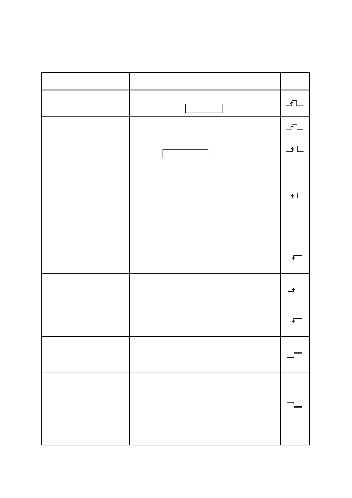
1.2.1 SOFTWARE DEDICATED INPUT SIGNALS
Signal Name Function
External motor power ON
(EXT. MOTOR ON)
External error reset
(EXT. ERROR RESET)
External cycle start
(EXT. CYCLE START)
External program reset
(EXT. PROGRAM RESET)
Turns the motor power ON externally. (Functions
in same way as the MOTOR ON key.)
Resets errors externally. (Functions in same way as
the <ERROR RESET> key .)
Sets the cycle start externally. (Functions in same
way as the CYCLE START key .)
Resets program externally . Input of this signal
during automatic operation stops cycle operation and
resets to the first step of the main program. When
RPS (external program selection) mode is set
effective, the RPSxx signals that were set when this
signal is input are imported and program step is reset
to the first step of the program specified by RPSxx
signals. (Refer to Appendix 2.)
Enables switching to another program specified by
Signal
Type
RPS-ON
JUMP-ON
JUMP-OFF
External program number
(RPSxx)
External HOLD (EXT_IT)
the external program number at the step where the
aux. data of END is taught. (Refer to Appendix 2.)
Enables switching to another program specified by
the external program number at the step where aux.
data of JUMP is taught. (Refer to Appendix 2.)
Disables switching to another program specified by
the external program number at the step where aux.
data of JUMP is taught. (Refer to Appendix 2.)
Sets up program number externally. The maximum
program number specified by RPSxx signals varies
with specification. (Refer to Appendix 2.)
Stops robot temporarily in repeat mode. (Valid in
repeat mode only.) When this signal circuit is open,
robot does not operate in repeat mode. When this
signal circuit opens during repeat mode, robot stops
immediately and cycle start stays ON. When this
signal circuit closes, robot resumes operation from
the place where it stopped.
9

E Series Controller 1. Types of External I/O Signal
Kawasaki Robot External I/O Manual
Signal Name Function
Signal
Type
External slow repeat
(EXT. SLOW REPEAT
MODE)
I/F panel page N selection
(I/F PANEL PAGE N
SELECT)
Auto save condition N
(AUTOSAVE COND. N)
External PC program N start
(External PC Program N
start)
External PC program N
Decreases repeat speed temporarily and externally.
The speed is set by Aux. function A-0508.
(Refer to Operation Manual.)
Displays the I/F panel on TP. The corresponding
I/F panel page is displayed when this signal is input.
Backs up robot data. The corresponding data is
saved based on the set condition when this signal is
input. Auto save conditions are set in A-210.
(Refer to the Operation Manual.)
Executes a PC program. Names of PC programs
executed by these signals are fixed. External PC
program 1 start signal executes the PC program,
“ZZEXTPC”. External PC program 2 to 5 start
signal executes “ZZEXTPC2” to “ZZEXTPC5”,
respectively.
Aborts a PC program. When each signal is input,
abortion
(External PC Program N
abort)
External motor power OFF
(EXT. MOTOR OFF)
Signal types indicated by “ ” or “ ” must be set
precisely for duration of 0.3-0.5 seconds. If the signal is
too short, it may not be reco gn iz ed. Also, d o not leave ON
the External motor power ON signal. When left ON and
E-STOP is applied, the stop is effective only while E-STOP
state is kept, and once released the motor power is reapplied
immediately.
system aborts the PC program corresponding to the
signal number .
Turns OFF the motor power ex ternally. Motor
power turns OFF when the contact closes. Do not
use this signal to turn OFF the motor power under
the condition on safety such as emergency stop,
because this signal is processed only on the software.
!
CAUTION
10

E Series Controller 1. Types of External I/O Signal
Kawasaki Robot External I/O Manual
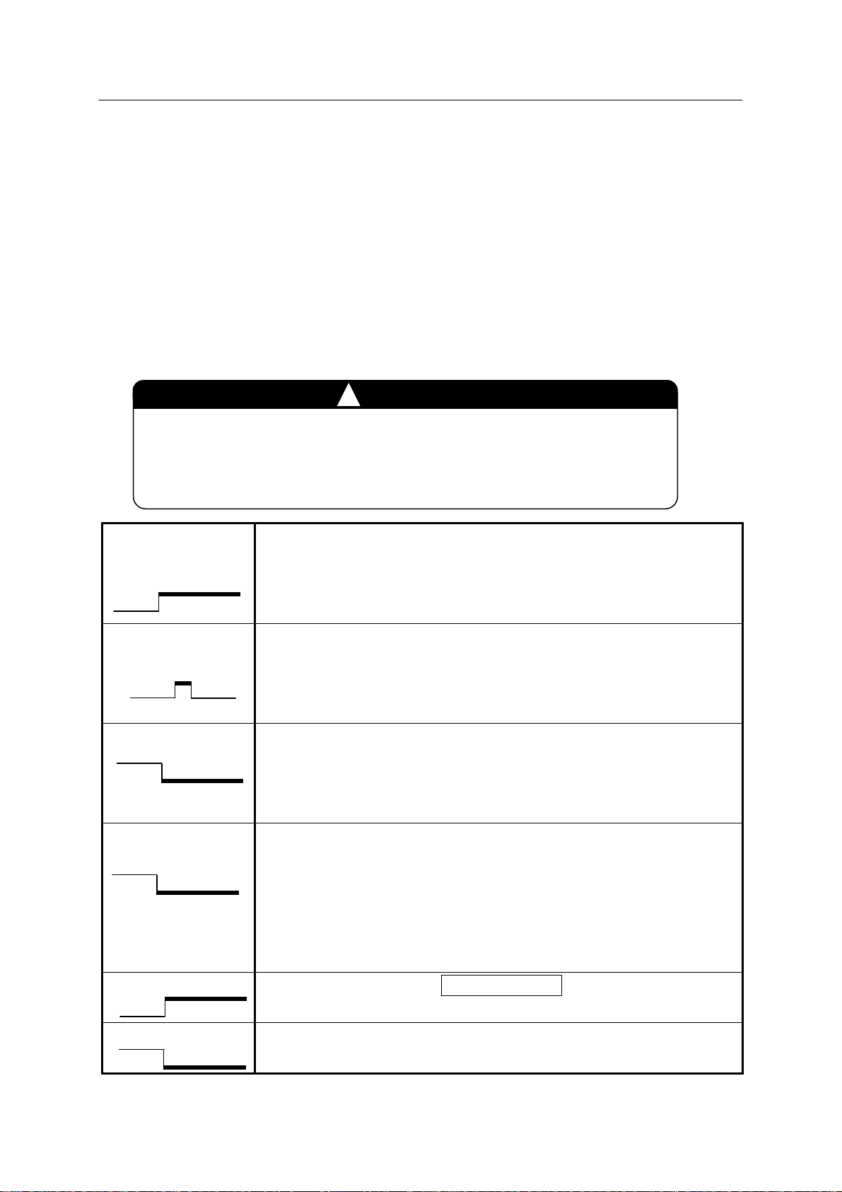
Explanation of Signal Type
: Leading edge is detected. Recommended for Pulse signals.
: Trailing edge is detected. Recommended for Pulse signals.
: Leading edge is detected.
: Level is detected.
11
E Series Controller 1. Types of External I/O Signal
Kawasaki Robot External I/O Manual
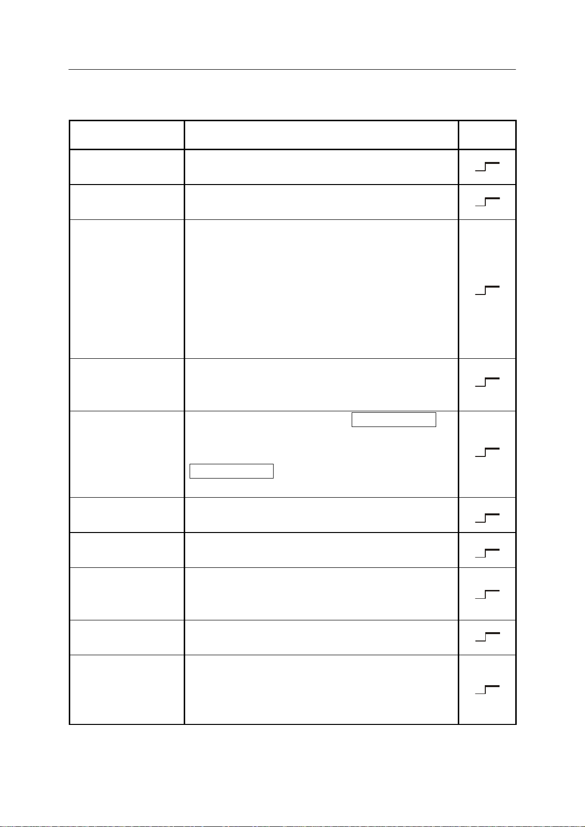
1.2.2 SOFTWARE DEDICATED OUTPUT SIGNALS
Signal Name Function
Motor power ON
(MOTOR ON)
Error occurrence
(ERROR)
Automatic
(AUTOMATIC)
Cycle start
(CYCLE STAR T)
Indicates that the motor power is ON. Functions in
same way as the MOTOR POWER lamp on TP.
Indicates that an error occurred. (Functions in same way
as the ERROR display on TP.)
Indicates that all the conditions set in Aux. function
A-0602 in respect to the following items are satisfied
when the robot is operable or in automatic operation.
1. Panel switch in RUN.
2. EXT_IT not set to hold.
3. Panel switch in
REPEAT.
4. Repeat continuous
Indicates that the robot is in automatic operation (in cycle
operation). Functions in same way as the CYCLE
START lamp on TP.
Indicates robot is in teach mode. (TEACH/REPEAT
Signal
Type
5. Step continuous.
6. TEACH LOCK OFF.
7. CYCLE START ON.
8. RGSO ON.
9. Dryrun mode OFF.
Teach mode
(TEACH MODE)
Home pose 1
(HOME1)
Home pose 2
(HOME2)
Power ON
(POWER ON)
RGSO
External program
selection effective
(Ext. prog. select
(RPS) enabled.)
switch is turned to TEACH on operation panel.)
Functions in same way as the output from the
TEACH/REPEAT switch in the hardware dedicated
signals.
Indicates robot is at the preset home pose 1. (Refer to
Appendix 3.0.)
Indicates robot is at the preset home pose 2. (Refer to
Appendix 3.0.)
Indicates controller power is ON.
Functions in same way as the CONTROL POWER lam p
on operation panel.
Is output when motor brake is released and robot is in the
servoing condition.
Is output when the external program selection mode is set
effective (RPS effective). (Refer to Appendix 2.0.)
12

E Series Controller 1. Types of External I/O Signal
Kawasaki Robot External I/O Manual
Signal Name Function
Indicates robot is ready to switch to the external program
Signal
Type
RPS-ST
JUMP-ST
Program number
(Program number)
Step number
(Step number)
Teach lock ON
(TEACH LOCK ON)
Auto save warning
(AUTO SAVE
WARNING)
Servo ready
(SERVO READY
STATUS)
number at the step where auxiliary data of END is taught.
(Refer to Appendix 2.0.)
Indicates robot is ready to switch to the external program
number at the step where auxiliary data of JUMP is
taught. (Refer to Appendix 2.0.)
The selected program number (xx part of pgxx) is output.
The step number of currently selected program is output.
Is output when teach lock is ON.
Is output when an error occurs during auto saving.
Is output in teach mode when servo system is neither in
error nor in emergency stop.
In PC program
execution
(External PC program
executing)
Emergency stop
(Under emergency
stop)
Dry run
(Executing dry run)
Hold
(Hold mode)
Safety fence open
(Safety fence opened)
Is output when a PC program is being executed.
Is output in emergency stop.
Is output in dry run mode.
Is output in hold mode (including external hold).
Is output when safety fence is open in repeat mode.
13
E Series Controller 1. Types of External I/O Signal
Kawasaki Robot External I/O Manual
1.3 GENERAL PURPOSE I/O SIGNALS
The general purpose I/O signals are assigned by block teaching or AS language program ming.
Signals are then output to ports or input from ports when executing the program in repeat mode.
They are connected to connectors CN2 and CN4 on 1TW board. (Refer to 2.0 Requirements for
Connecting External I/O Signals.)
In terms of hardware configuration, the general purpose I/O signals are the same as software
dedicated signals. Software dedicated signals are defined in advance and used for condition
output, remote operation, and dedicated functions. General purpose signals are used freely
depending on each robot application.
!
WARNING
1.3.1 TYPES OF GENERAL PURPOSE SIGNALS
There are two types of general purpose I/O signals, signals for communicating externally and
signals that can only be used internally . This manual describes only external I/O signals. For
internal I/O signals, see A S Language Reference Manual.
Avoid using only a general purpose signal for safety interlock.
!
When assigning general purpose signal numbers and functions,
ensure that they are not duplicates of those previously assigned
as hardware or software dedicated signals, or other general
purpose signals. If duplicate assignments are made, the
conflict may cause the controller to function unpredictably.
CAUTION
For the E series controller , external I/O signals can be increased in increments of 32 channels.
They contain both general purpose and software dedicated signals. When determining the
system, take into account that the software dedicated signals occupy a portion of the total external
I/O signal quantity.
Expansion of external I/O signals is made in increments of 32
input and 32 output channels. The channel quantities for input
and output are the same due to the hardware structure.
[ NOTE ]
14
E Series Controller 1. Types of External I/O Signal
Kawasaki Robot External I/O Manual
1.3.2 I/O TIMING OF GENERAL PURPOSE SIGNALS
Teaching procedure for general purpose signals is dif ferent for block teachin g and AS language
programming. Fully understand the I/O timing of general purpose signals before using.
1.3.2.1 I/O TIMING THROUGH TEACHING
In block teaching, the information below is taught together all at once in each step using teach
pendant.
1. Pose data of robot arm
2. Auxiliary data (Interpolation, speed, accuracy , clam p, tool and general purpose I/O (OX/WX)
signal)
The general purpose signals taught in block teaching are called OX (output) and WX (input)
signals. The timing of OX and WX when executing a program taught by block teaching is
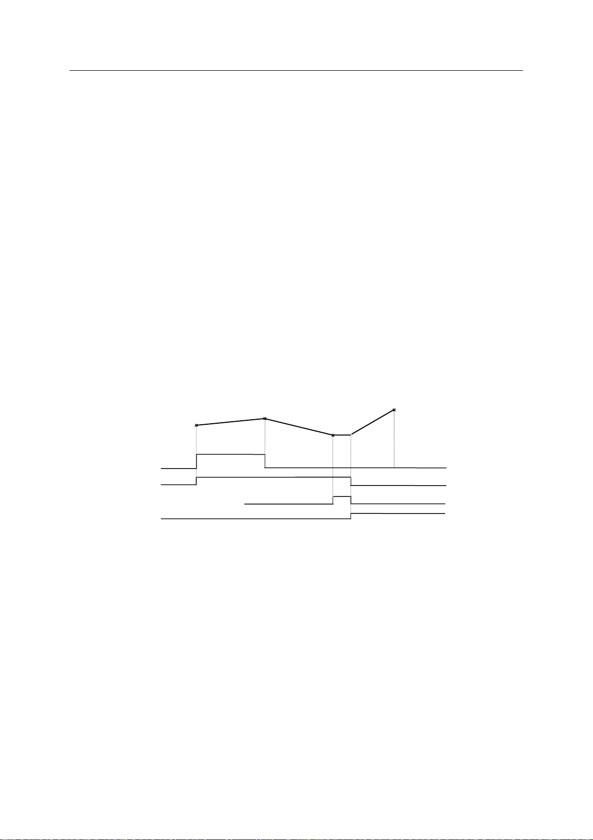
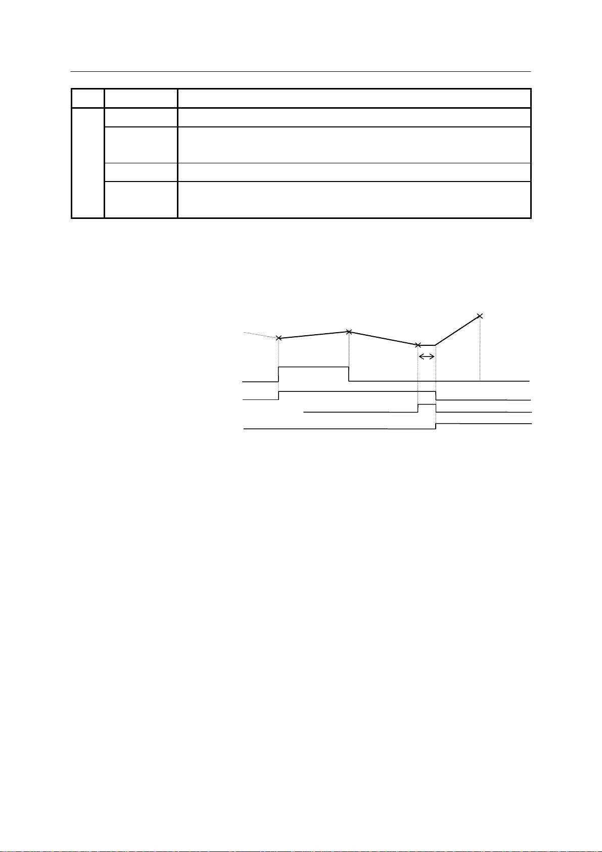
shown in the example below.
Step 7
OX5
OX6
WX3 (Input waiting range)
WX3
System Switch OX.PREOUT ON
Step 8
OX5
OX6
Step 9
OX6
WX3
Step 10
If OX5 is taught in step 8:
1. When robot reaches the accuracy range of step 7 and starts to approach the taught point of
step 8, OX5 turns ON.
2. When robot reaches the accuracy range of step 8 and starts moving toward the taught point of
step 9, OX5 turns OFF because it is not taught in step 9.
If OX6 is taught in steps 8 and 9:
1. When robot reaches the accuracy range of step 7 and starts to approach the taught point of
step 8, OX6 turns ON.
2. When robot reaches the accuracy range of step 8 and starts moving toward the taught point of
step 9, OX6 remains ON because it is taught in step 9.
15
E Series Controller 1. Types of External I/O Signal
Kawasaki Robot External I/O Manual
3. Normally, upon reaching the accuracy range of step 9, the robot starts to approach the taught
point of step 10 and OX6 is turned OFF immediately (because OX6 is not taught in step 10).
In this example, however, the controller waits for input of WX 3, because WX3 is taught in
step 9. Step 9 does not switch to 10 until WX3 is input.
4. When W X3 is input, the step switches to 10 and OX6 turns OFF.
If WX3 is taught in step 9:
1. When robot reaches the accuracy range of step 9, it checks for WX3 input.
2. When W X3 has been input, robot m oves to the taught point of step 10. If not yet, the robot
keeps waiting at step 9 until it is input.
1.3.2.2 I/O TIMING THROUGH AS PROGRAMMING
Besides block teaching (OX and WX signals) described above, general purpose I/O signals can
also be taught by programming via AS Language. By programming with this method, general
purpose I/O signals have a much wider application scope than OX and WX signals and can be
1. OX signals turn OFF when robot stops due to: motor power OFF, cycle start
OFF or HOLD. The OX signals turn ON again after restarting.
2. Switching from one step to the next occurs when the robot reaches a taught
step, but the switching does not always coincide with the taught point. It
depends on accuracy data of the taught step. The more accurately it is set,
the closer the switching point will be to the taught point. The rougher it is
set, the earlier the step switches. Therefore, note that the timings of input
and output change depending on the accuracy range taught at that step.
!
CAUTION
used in various ways. The following list of instructions is used for controlling general purpose
I/O signals. See AS Language Reference Manual for more details.
Instruction Function
SIGNAL Turns ON/OFF the general purpose output signals (individual)
BITS Turns ON/OFF the general purpose output signals (in a group)
RESET Turns OFF the general purpose output signals (effects all the signals)
RUNMASK Controls the general purpose output signals at robot stop
control
PULSE Pulse output for the general purpose output signals
Output signal
DLYSIG Delayed output for the general purpose output signals
16
E Series Controller 1. Types of External I/O Signal
Kawasaki Robot External I/O Manual
Instruction Function
SWAIT Waits until conditions for the general purpose input signals are satisfied.
SIG( ) Determines if conditions are satisfied for the general purpose input
signals.
BITS( ) Reads the general purpose input signals specified by its parameters.
control
Input signal
ON/ONI Interrupts program execution upon receiving the general purpose input
signals.
The timing of general purpose I/O signals when programming with AS Language is shown in the
example below. (Assuming that the system switch is OFF for PREFETCH. SIGINS.)
Program example:
11 JMOVE #lc1
12 SIGNAL 5,6
13 JMOVE #lc2
14 SIGNAL -5
15 JMOVE #lc3
16 SWAIT 1003
17 SIGNAL -6
18 JMOVE #lc4
OUT5
OUT6
(Input waiting range)
IN3
IN3
System Switch PREFETCH.SIGINS OFF
#lc1
#lc2
#lc3
#lc4
Wait
The above timing chart is valid when accuracy for positioning (a value specified by ACCURACY
instruction) is programmed to be precise. If the accuracy is rough, transitions occur before the
robot reaches the actual taught point.
OUT5:
1. General purpose output signal (OUT5) turns ON when robot starts moving to #1c2.
2. After robot reaches #lc2 and the robot starts moving to #lc3, OUT5 turns OFF.
OUT6:
1. General purpose output signal (OUT6) turns ON when the robot moves to #1c2.
2. After reachin g #lc2, robot starts m oving to #lc3. OUT6 remains ON.
3. General purpose output signal (OUT6) turns OFF when robot m oves to #1c4.
IN3:
1. Robot starts monitoring the general purpose input signal (IN3) once it starts moving to # lc3.
2. Robot waits because IN3 is not ON in this example when reaching #1c3.
17

E Series Controller 1. Types of External I/O Signal
Kawasaki Robot External I/O Manual
3. Robot moves to #lc4 when IN3 turns ON. If IN3 is ON after robot has started signal
monitoring but before arriving at #1c3, then the monitoring is disabled immediately and the
robot moves to #1c4 without waiting.
!
CAUTION
Generally, OUT signals do not turn OFF when the robot stops due to
motor power OFF or HOLD, unlike OX signals. If defined by
RUNMASK instruction, OUT signals will function like OX signals,
turning OFF when program execution is interrupted.
18
E Series Controller 2. Requirements for Connecting External I/O Signals
Kawasaki Robot External I/O Manual
2.0 REQUIREMENTS FOR CONNECTING EXTERNAL I/O SIGNALS
Requirements for connecting external I/O signals differ for hardware signals and general purpose
I/O signals (including software dedicated signals).
2.1 HARDWARE DEDICATED SIGNALS
When using the hardware dedicated signals, connect them to the terminal block on 1TR board
and comply with the requirements below.
2.1.1 EXTERNAL CONTROL POWER ON/OFF
This input signal turns the DC power supply (AVR) for the controller ON/OFF externally .
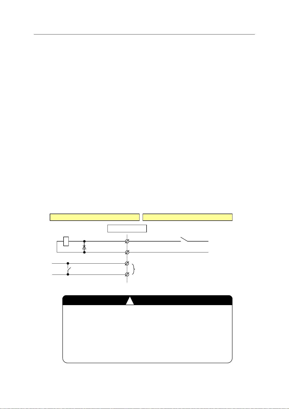
1. When using external control power ON/OFF
Leave the connection between pins 3 and 4 open and apply +24 V to pin 1 and 0 V to pin 2 of
terminal block connector X9 on 1TR board. Connect pins 1-4 of connector X9 as shown in
figure below .
Controller External
(1TR board)
(1KP B oa rd)
Connector X9
1
2
3
Do not connect
4
Switc h o r Relay c o nta ct
Contact close : Control power ON
Contact open : Control power OFF
+24V
External
0V External
1. Take caution when connecting pins 1 and 2 of connector X9.
If connected incorrectly, damage to the 1TR board or external
power supply may occur.
2. Err or “D1560 [Power sequence board] DC 24V is abnormal.”
occurs when DC power is turned OFF by this input but this is
not abnormal.
!
CAUTION
19
E Series Controller 2. Requirements for Connecting External I/O Signals
Kawasaki Robot External I/O Manual
!
CAUTION
1. Use a switch or relay contact that meets the following specifications:
Contact power capacity : DC24 V 0.2 A or more
(Relay coil specification DC24 V 10 mA 20 %)
Power supply : DC24 V 10 %
(Connect 0 V side to the ground.)
2. An interval of 2–3 seconds is required between the time when control power is
turned OFF (contact open) to ON (contact close).
3. Use 22-24 AWG (0.2-0.3 mm2) for the connector wiring material.
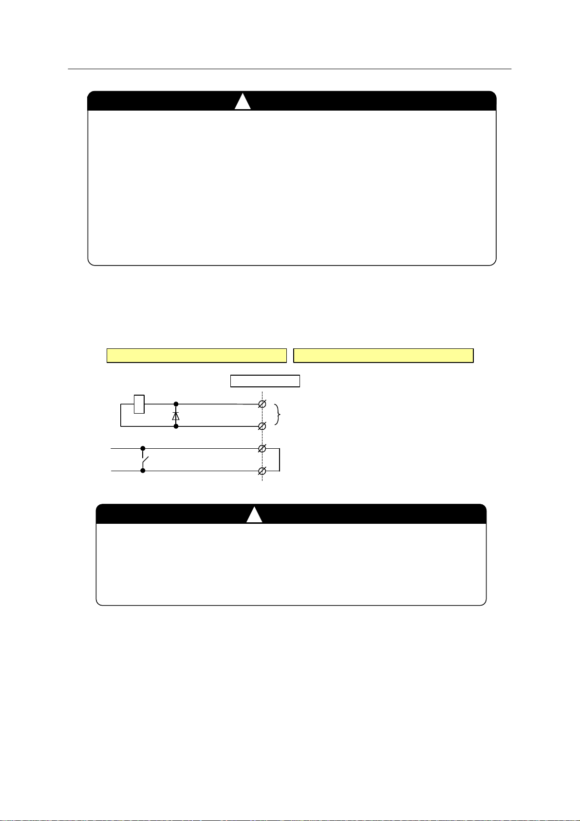
2. When not using external control power ON/OFF
Connect pins 1-4 of terminal block connector X9 on 1TR board as shown below.
Co ntro lle r Ex tern al
Connector X9
1
2
Do not connect
(1TR board)
(1KP B oa rd )
3
4
Jumper
Pins 3 and 4 of connector X9 are jumpered when controller is factory shipped.
When using external control power ON/OFF, make sure that the jumper is
removed and connection to the connector X9 is configured as shown in the
previous page.
!
CAUTION
20

E Series Controller 2. Requirements for Connecting External I/O Signals
Kawasaki Robot External I/O Manual
2.1.2 EXTERNAL MOTOR POWER ON
This input signal turns the motor power ON externally and has the same function as the
MOTOR ON key.
Never leave ON the External motor power ON signal (contact close).
If left ON the robot may move unexpectedly, for example after an
emergency stop is released.
!
WARNING
1. When using external motor power ON
T o turn ON the m otor power, close connection between pins 5 and 6 of terminal block
connector X9 on 1TR board. Connect a switch or relay contact between pins 5 and 6 of
connector X9. Use a pulse input signal as the contact must not remain closed.
+24V Internal
0V Internal
Controller External
Connector X9
5
6
Switch or Relay contact
(1KP Board)
(1TR board)
Motor power is turned ON when the switch or
relay contact is closed for 0.3 - 0.5 second.
1. Use a switch or relay contact that meets the following specifications:
Contact power capacity: DC24 V 0.2 A or more
2. Use 22-24 AWG (0.2-0.3 mm
!
CAUTION
2
) for the connector wiring material.
2. When not using external motor power ON
Open connection between pins 5 and 6 of terminal block connector X9 on 1TR board and do
not connect any wiring to them.
21
E Series Controller 2. Requirements for Connecting External I/O Signals
Kawasaki Robot External I/O Manual
2.1.3 SAFETY CIRCUIT OFF
This input signal shuts OFF the motor power externally. When this signal circuit opens, motor
power is shut OFF. The following 3 types of input signals are available for safety circuit.
1. External emergency stop (Valid in teach and repeat mode.)
2. Safety fence input (Valid only in repeat mode.)
3. External trigger input (Valid only in teach mode.)
!
WARNING
2 safety circuits are provided on this controller . E1x/E2x/E73/E74/E94 controller can be
configured with only one safety circuit, however, it should be configured wi th 2 safety circuits
unless there is some particular reason. When using only one safety circuit, make the settings as
The Safety circuit OFF needs to be designed based on IEC60204-1, ISO10218
and ISO13849-1, because its function and operation is very important for
human safety. Safety circuit of E3x/E76/E77/E97 and E4x/E70/E71/E91/E94
controllers and safety circuit of E1x/E2x/E73/E74 controller satisfy
requirements of PLd in category 3 and requirements of PLc in category 2
defined by ISO 13849-1:2006, respectively. (When E1x/E2x/E73/E74/E94
controller is configured with one safety circuit as shown below, the safety
circuit does not satisfy the requirements of PL in above category. Optional
safety circuit of E1x/E2x/E73/E74 controller also supports PLd in category 3.)
When constructing the comprehensive safety system including robot, conduct
risk assessments and make sure that safety circuit of the controller satisfies
performance requirements.
shown below. E3x/E76/E77/E97 and E4x/E70/E71/E91 controllers cannot be configured with
only one circuit.
Item Setting
1. Dip switch SW2-1 on 1TR board ON
2. Jumper, JP2 or JP3 on 1TV board (MC unit)
or 1VH board
Insert the jumper into JP3 with JP2 open
22

E Series Controller 2. Requirements for Connecting External I/O Signals
p
Kawasaki Robot External I/O Manual
Cover
late
without
cover plate
E73/E74 controller
For 2 safety
circuits
1TV board
For 1 safety
circuit
Rear
1TV board
MC unit
E1x/E2x controller
For 1 safety
circuit
E94 controller
(without the top cover)
1VH board
23
For 2 safety
circuits
E Series Controller 2. Requirements for Connecting External I/O Signals
[
]
Kawasaki Robot External I/O Manual
E1x/E2x/E73/E74/E94 controller should be configured with 2 safety circuits
unless there is some particular reason. When using the E1x/E2x/E73/E74/E94
controller with 1 safety circuit, conduct enough risk assessments before using it.
Turn OFF the controller power when switching the safety circuit configuration.
The following errors may occur in the safety circuit construction. When error occurs,
perform the appropriate troubleshooting as shown below.
Error Countermeasure
!
!
WARNING
CAUTION
NOTE
Inconsistent condition
in safety circuit
Fuse blowout in
safety circuit
2.1.3.1 EXTERNAL EMERGENCY STOP
This has the same function as the EMERGENCY STOP switch on the operation panel.
1. Use a contact circuit (mechanical contact) for turning external E-STOP
ON/OFF. Using a semiconductor circuit is extremely dangerous as shut OFF
of the motor power may become inoperable if there is a system failure.
2. Never jumper pins 2-4 and 6-8 of X7 connector. Jumpering these pins disables
E-STOP switches on the operation panel, teach pendant and on external
Check the wiring of terminal block connector (X7, X8) and the
inconsistent part indicated in the error message. To reset error, both
contacts of the inconsistent part must be turned OFF once. (This
error only occurs when using 2 safety circuits.)
F1 fuse (1 A) on 1TR board is blow n out. Check if the connection to
safety circuit (connector X7, X8) is correct, and replace the fuse.
!
WARNING
E-STOP safety circuit, and robot w ill not stop when E-STOP switches are
3. Use external E-STOP switches that meet the following specif ications:
(1) Contact power capacity: DC24 V 1 A or more
(2) Conformance with safety standards
(3) Positive opening mechanism (marked with )
(4) NC (Normally Closed) contact
(5) 2 contacts or more (for 2 safety cir cuits)
24
E Series Controller 2. Requirements for Connecting External I/O Signals
[
]
Kawasaki Robot External I/O Manual
4. Use an external E-STOP circuit relay that meets the following specifications:
(1) Contact power capacity: DC24 V 1 A or more
(2) Conformance with safety standards
(Do not use general control relay as it may not satisfy the safety
standards.)
(3) Forced-guided type
5. Use 22-24 AWG (0.2-0.3 mm2) for the connector wiring material.
6. Connect 0 V External to the ground.
!
WARNING
NOTE
When using Cubic S, X7 connector is connected with Cubic-S and connect external
emergency stop signal to the Cubic-S. See 90210-1272DE* for details.
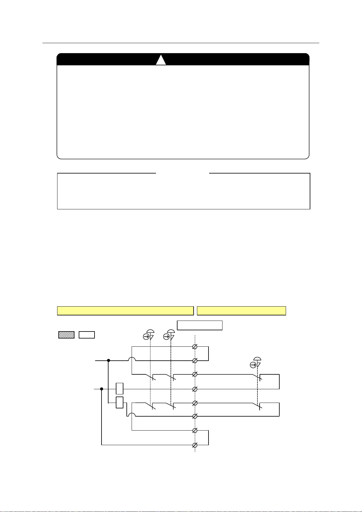
1. When using external emergency stop
(1) For connecting external switch contact dir ectly in two safety circuits
Remove jumpers between pins 3-4 and 5-6 of terminal block connector X7 on 1TR board,
and connect emergency stop switch contacts as shown below. Jumper pins 1-2 and 7-8.
Also, set jumper to the JP1 pins on 1TR board.
JP1
JP2
Controller External
OP
T/P
Connector X7
+24V In ter nal
1
2
3
Jumper
Internal
0V
4
5
6
(1TR board)
(1KP B oa rd)
7
8
Jumper
External
E-STOP
Switc h
25
E Series Controller 2. Requirements for Connecting External I/O Signals
r
l
r
Kawasaki Robot External I/O Manual
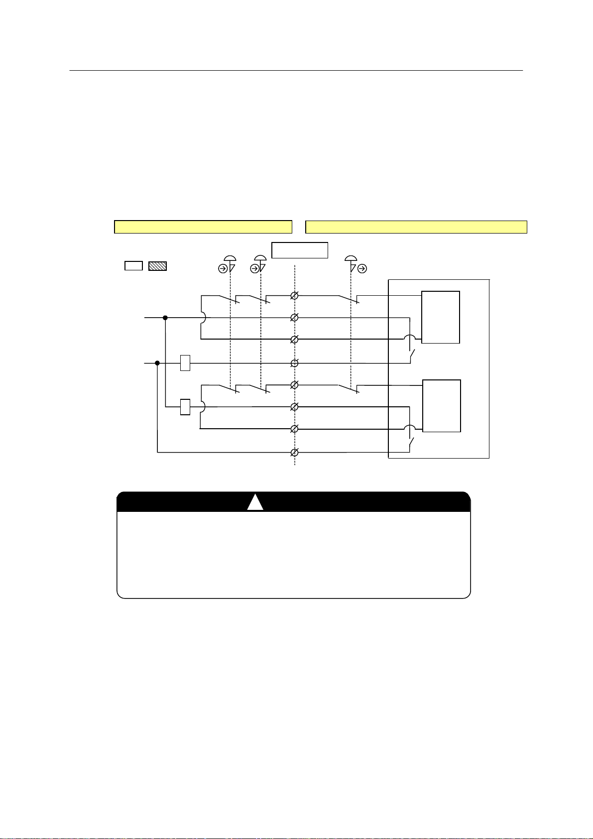
(2) For configuring 2 external safety circuits with external emergency stop input and
emergency stop contacts taken out from the controlle r
On connector X7, remove all jumpers from pins 1-2, 3-4, 5-6, and 7-8. Take out the
emergency stop contacts connected between pins 1-3, 5-7 from the controller. Also, set
jumper to the JP2 pins on 1TR board. Connect external stop contacts to pins 2-4, 6-8 on
connector X7.
+24V Internal
0V Internal
Controlle
JP1 JP2
(1TR board)
Externa
External emergency
T/P
OP
!
X7 connecto
1
2
3
4
5
6
7
8
WARNING
stop switch
Safety relay module
Output 1
Output 2
Input 1
Input 2
Set jumper to the JP2 pins on 1TR board when taking out the
emergency stop switch contacts from the controller. If the
jumper is set to the JP1 pins, circuits for emergency stop monitor
may exert a harmful influence on external circuits.
26
 Loading...