

Page 1
Industrial stationary
vacuuming systems
Planning Manual
English 5.906-587.0 Rev. 00 (05/14) 1
Page 2

2 English 5.906-587.0 Rev. 00 (05/14)
Page 3

Contents
1 Safety instructions 5
1.1 Hazard levels 5
2 When is a central vacuuming system used? 5
3 Target groups for a central vacuuming system 5
4 Advantages of a stationary vacuuming system 5
5 Abstract of the system planning 5
6 Components of a stationary vacuuming system 5
6.1 Suction unit 5
6.2 Collection and disposal container 5
6.3 Filter 5
6.4 Formed parts pipeline 5
6.5 Hose connections and switches 5
7 Prerequisite system planning 6
8 Basics of the system planning 6
8.1 Air speed 6
8.2 Route planning 8
8.3 System planning 8
9 Calculation tool 9
9.1 Calculation tool pipeline system 9
9.1.1 Modes of calculation 10
9.1.2 Conversion of units 13
9.1.3 Calculator 13
9.2 Calculation tool calculation of the pressure loss 14
10 Calculation of the pressure loss 15
10.1 Pressure loss calculation with the calculation tool 16
10.2 Addition of the sections 17
10.3 Alignment with vacuum cleaner characteristic 17
11 Sample calculation for the dimensioning of the vacuum cleaner 18
11.1 Step 1 18
11.2 Step 2 18
11.3 Step 3 18
11.4 Step 4 18
11.5 Step 5 19
11.6 Step 6 19
11.7 Step 7 20
11.8 Step 8 20
11.9 Step 9 20
12 Basics of the system installation 23
12.1 Overview module components 23
12.2 Examples for correct and incorrect system installation 24
12.3 Examples for the correct and incorrect branchings in the pipeline network 24
13 Use and setting of the false air valve 25
14 Installation instructions for tension ring connections with flanged sealing ring 26
15 Producing a flanged edge 28
15.1 Information concerning border sealings 28
16 General mounting instructions for the creation of tight connections 29
16.1 Installation instructions earthing bridge 29
17 Commissioning remote control 30
English 5.906-587.0 Rev. 00 (05/14) 3
Page 4

17.1 Selecting the setup location 30
17.2 Installation 30
17.3 Functional description 30
17.4 Parameter IV vacuum cleaner control 30
18 Annex 1 - Questionnaire central vacuuming systems 5.906-589.0 31
18.1 Customer details 31
18.1.1 Preface 31
18.2 Checklist product 31
18.3 Checklist system 32
18.4 Other information 33
19 Annex 2 - Motor characteristics 34
20 Annex 3 - Pipe programme 35
4 English 5.906-587.0 Rev. 00 (05/14)
Page 5

1 Safety instructions
5 Abstract of the system planning
1.1 Hazard levels
CAUTION
Possible hazardous situation that could lead to mild injury
to persons or damage to property.
Note
Indicates useful tips and important information.
2 When is a central vacuuming system
used?
– If the area to be vacuumed is locally fixed.
– If there is little space available at the working area.
– If the working areas are laid out over a large area and
several vacuuming points are therefore required.
– If the possible cleaning times must be limited due to the
production continuity
– If set-up and maintenance times are to be minimised.
– If the work environment must be kept hygienically
clean.
– If engine noises must be minimised in the working area.
– If large amounts of dust or fluid must be continuously
disposed of.
3 Target groups for a central
vacuuming system
Typical target groups for stationary vacuuming systems:
– Food industry
– Processing of metal and steel
– Processing of glass and stone
– Production of paper
– Production of starch and tobacco
– Textile industry
– Automobile industry
– Construction
– Transport
4 Advantages of a stationary
vacuuming system
– Immediately ready for operation, no set-up times.
– Space-saving, only the vacuuming accessories are at
the work station.
– Comfortable to use and safe to operate.
– Central suction unit and emptying at one point, thus,
space-saving and time-saving during maintenance.
– Long service life as parts transporting materials are
made of robust, sturdy material.
– Saving of costs thanks to the lower maintenance cost
of the entire system compared to several single systems.
– Saving of costs thanks to the acquisition costs com-
pared to single systems.
1 Description of the requirements and evaluation of the
situation of the customer.
2 Based on the known amount of material and material
characteristics to be vacuumed up, the number and
size of the vacuuming points and the resulting required
air speed is determined.
3 Planning of the routing.
4 Calculation of the pressure loss in the network with the
objective to optimise the line design
5 Matching with the vacuum cleaner types and detailed
planning of the routing.
6 Components of a stationary
vacuuming system
6.1 Suction unit
– All Kärcher industrial vacuums.
– Wet / dry vacuum cleaner and liquid aspirator.
– Explosion-proof vacuum cleaners are only certified for
the operation with defined hose lines.
The certification comprises a test of the total resistance
in the system (vacuum cleaner without accessories)
For a stationary system this can not be performed in ad-
vance.
If a customer requires an explosion-proof stationary
system, the installed system must be certified in a sin-
gle acceptance inspection by the named authority.
6.2 Collection and disposal container
– Container sizes and types as per the current main cat-
alogue.
– The pre-separator system (as per main catalogue) with
80 l container or for drums can also be used as a dis-
posal container (observe nominal diameter).
– Disposal bags in various designs as per main cata-
logue.
6.3 Filter
– All IV- and IVC vacuum cleaners have an integrated cy-
clone preseparator.
– Filter data of the main filters such as surface, material,
order number, etc. as per main catalogue.
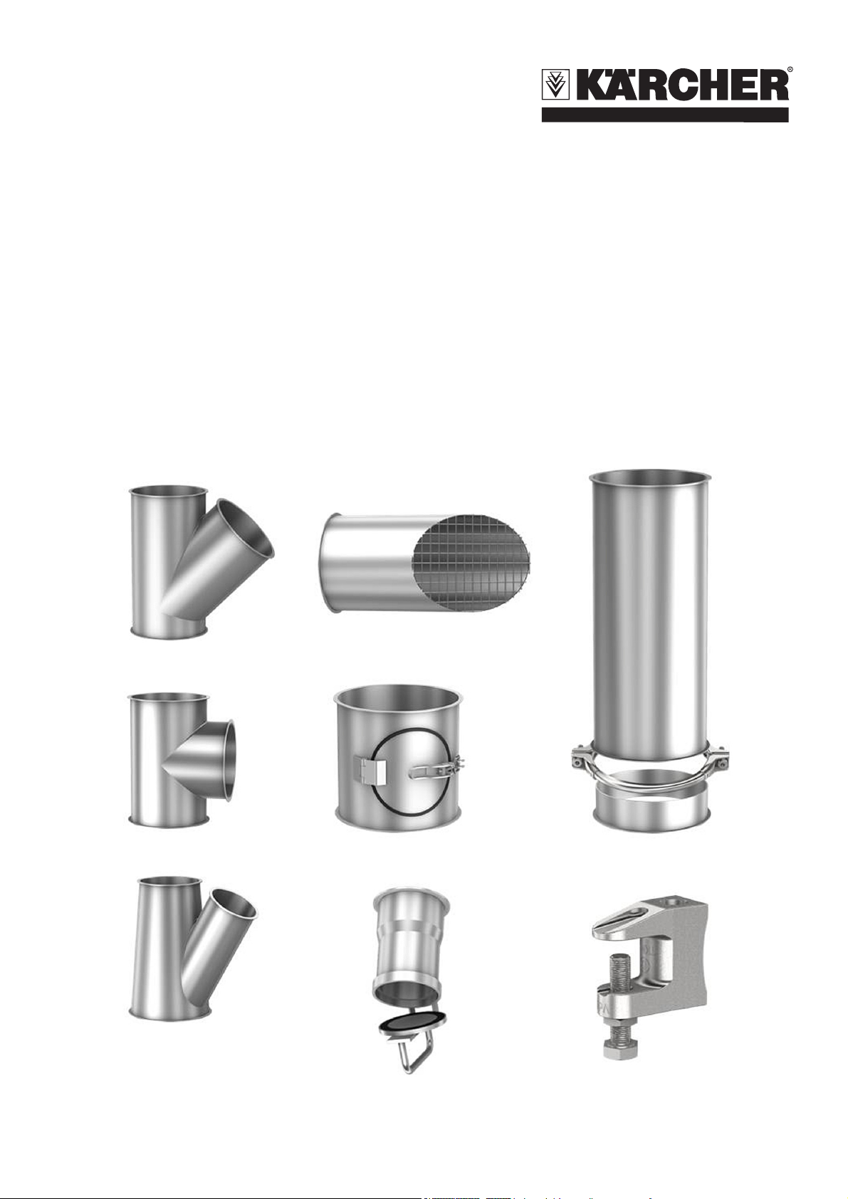
6.4 Formed parts pipeline
– 4 Standard diameter:
DN 60, DN 80, DN 100 and DN 120
– Modular system with flanged pipes and tension ring
connections.
Thus, flexible replacement and extension.
– In galvanised steel or stainless steel (1.4301)
– System is suitable for dusts, chips and fluids.
6.5 Hose connections and switches
– Hose suspension with limit switch for the automatic
switch-on of the vacuum cleaner.
– Kärcher remote control for controlling the suction unit at
the vacuuming point.
English 5.906-587.0 Rev. 00 (05/14) 5
Page 6
7 Prerequisite system planning
– Clarify with the customer in detail which requirements
the stationary system should fulfil.
The questionnaire for central vacuuming systems
5.906-589.0 helps, see Chapter "Annex 1 - Questionnaire central vacuuming systems 5.906-589.0“.
– The system design is based on the number of suction
stations to be operated in parallel and the amount of
material to be transported per vacuuming point.
8 Basics of the system planning
8.1 Air speed
Air is the transport medium for the vacuumed material. To
ensure that the vacuumed material is transported in the
entire pipeline network without depositing (material deposit) and clogging, a steady air speed must be present in the
network.
The required air speed varies for different vacuumed materials.
On its way through the line network the individual particle
of the vacuumed material does not fly straight from the
suction station to the disposal container. Thus, it always
requires more time from the vacuuming point to the disposal container than the air speed gives you reason to expect.
For this reason, an after-running time of the vacuum cleaner must always be provided for to prevent depositing due
to early switch-off.
Note
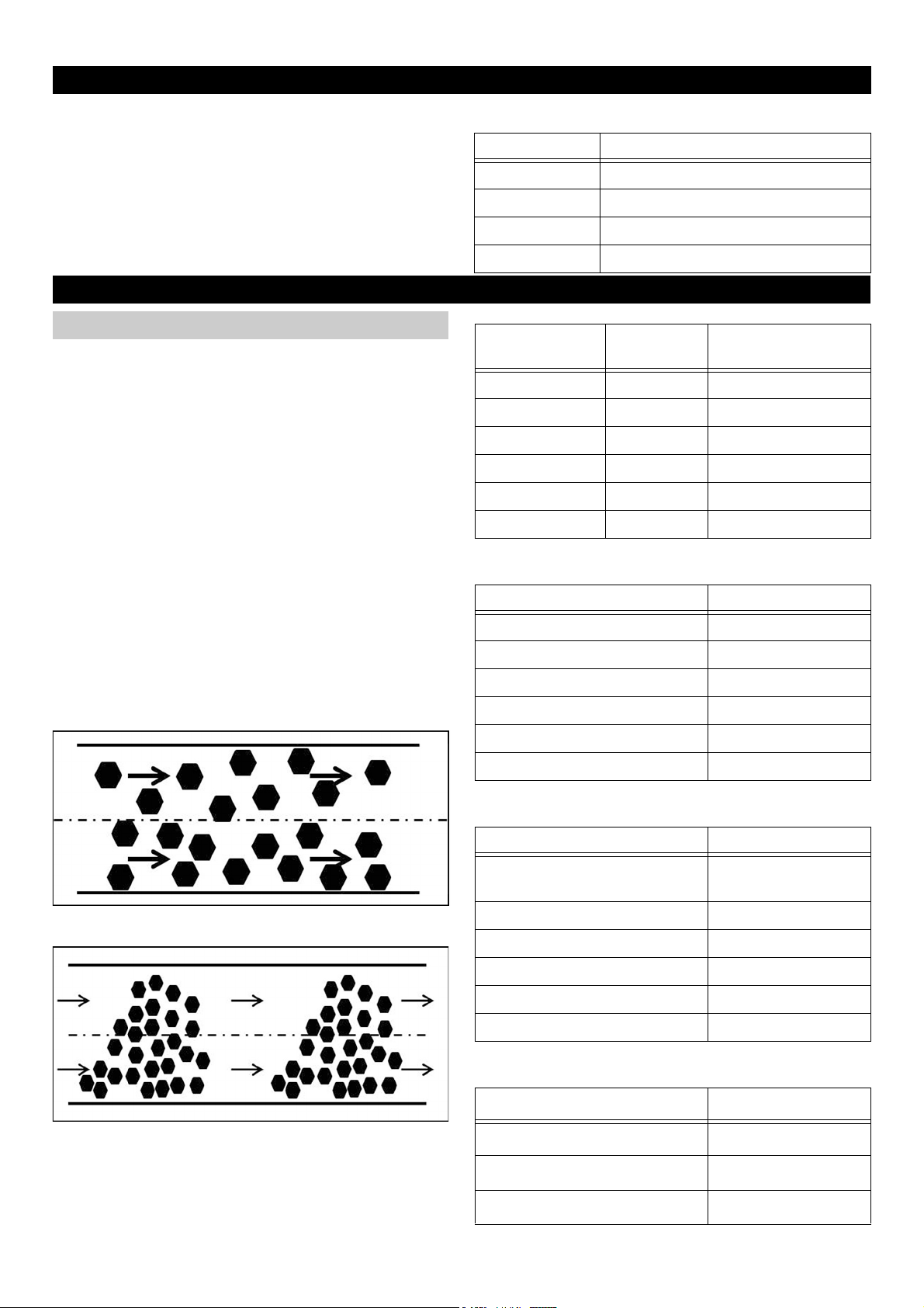
The perfect and thus targeted conveyance in the pipeline
is the flying transport.
Flying transport
Flow rate with an air speed of 20 m/s:
Suction hose Volume flow (flow rates/h)
DN 42 approx. 90 m³/h
DN 51/52 approx. 140 m³/h
DN 61 approx. 200 m³/h
DN 71/72 approx. 270 m³/h
Vacuumed material
Wood chips 50x20x1 mm 22-25 m/s
Sawdust (wood) Ø 0.7 mm 20-25 m/s
Steel balls Ø 1 mm 25-35 m/s
Active carbon Ø 3 mm 20-23 m/s
Plastic granules Ø 3.5 mm 20-23 m/s
Plastic powder Ø 0.2 mm 20-25 m/s
Area wood
Vacuumed material Air speed
Wood chips with pieces 25-30 m/s
Sawdust damp 22-24 m/s
Coarse wood chips without pieces 18-22 m/s
Wood wool 18-20 m/s
Small wood and planing pieces 16-18 m/s
Dimensions Air speed
Clogging transport
The smaller values can only be used with lines that are designed in a way that is favourable for the flow, e.g. with
short or vertical lines, elbows with a large radius, fork pieces with a small angle.
Finest wood dust 12-14 m/s
Area metal
Vacuumed material Air speed
Very coarse metal dust and
chips
Coarse metal dust and chips 20-22 m/s
Metal dust, chips 18-20 m/s
Fine metal dust 16-18 m/s
Metal smokes (welding) 14-16 m/s
Finest metal dust 12-14 m/s
Area food
Vacuumed material Air speed
Tobacco dusts 15-16 m/s
Grain and feeding stuff dusts 14-16 m/s
Flour 12-14 m/s
20-25 m/s
6 English 5.906-587.0 Rev. 00 (05/14)
Page 7

Area paper, plastics
Vacuumed material Air speed
Scrap of paper 15-22 m/s
Rubber dust 18-20 m/s
Trimming suction 16-18 m/s
Swarf leather 15-16 m/s
Paint mist spray booth 14-16 m/s
Shorter textile fibres 12-16 m/s
Foamed polystyrene (expanded
polystyrene)
Area minerals
Vacuumed material Air speed
Coarse dry sand without gravel 18-20 m/s
Sandblasting, fettling shop 16-18 m/s
Swarf glass 16-18 m/s
Emery, corundum 116-18 m/s
Sand 14-16 m/s
Finest dry sanddust 12-14 m/s
Other
Vacuumed material Air speed
Detergent dusts 16-18 m/s
Oil mist suctioning 14-16 m/s
Coal dust pulverized 12-14 m/s
8-10 m/s
English 5.906-587.0 Rev. 00 (05/14) 7
Page 8
8.2 Route planning
Note
The objective is to keep the resistance in the pipeline system as small as possible.
– Always choose the shortest possible way.
– Course as straight as possible with as few cracks and
bends as possible.
– Use of the ways of other supply runs e.g. of present
pipelines, cable runs etc.
– No obstruction of ways or systems.
– Provide for easily accessible cleaning opening.
– Optimum installation height is 2-3 m.
– Plan the junctions on the same height or with a slight in-
cline to the main line.
– Always align Y-pieces to the side, never towards the
top or bottom (medium can drain).
– The overall cross section of the nozzle at the machine
to be vacuumed off and its branch should not exceed
the cross sectional area of the suction stub at the vacuum cleaner.
– The suction stub at one single machine must not be
larger than the total connection cross section at the
vacuum cleaner.
– 90° junctions (tees) must be avoided in general.
– With longer branch lines the cross section of the pipe-
line should be chosen larger than the suction nozzle
connection.
– A taper of the pipe cross section must only be designed
smaller from the vacuum cleaner to the vacuuming
points and should be as close as possible to the vacuuming point.
– Every vacuuming point should be equipped with a lock-
ing slide that is always closed after the switch-off of the
machine or the end of the suction process.
– Hoses have a high pressure loss due to their large fric-
tional resistance. Due to this circumstance, the hose
lengths must be reduced to a minimum.
– Always use a hose sleeve at the end of the hose, and
earth the wire helix of the hose on the hose sleeve by
means of a screw in order to create a potential equali-
sation.
– All pipelines must be connected in an electrically con-
ductive way from the machine branch to the intercept-
ing pipe.
8.3 System planning
With the 4 given framework requirements a rough planning
of the stationary system can take place.
1 Spatial conditions.
2 Number of the overall and the simultaneously working
vacuuming points.
3 Required air speed.
4 Kärcher vacuum and pipeline programme.
Part one "Design pipe system" of the calculation tool for
stationary vacuuming systems can be used for the calculation of the pipe diameter (see Chapter "Calculation tool
pipe system design").
The inner diameter is calculated respectively and the pipe
closest to the calculated diameter is chosen.
With the fixed pipeline diameter the air speed actually
achieved must be calculated again.
If it does not suffice for the material to be vacuumed, the
pipeline must be redesigned or a more powerful vacuum
cleaner must be used.
8 English 5.906-587.0 Rev. 00 (05/14)
Page 9
9 Calculation tool
The calculation tool can be called up online via the DISIS
and in SAP under the part number 5.906-608.0.
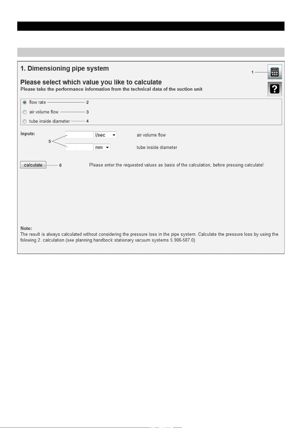
9.1 Calculation tool pipeline system
1 Auxiliary tool for the conversion of units and calculator
2 Selection "flow rate"
3 Selection "Air volume flow"
4 Selection "Inner pipe diameter"
5 Input fields
6 Button "Calculate"
English 5.906-587.0 Rev. 00 (05/14) 9
Page 10
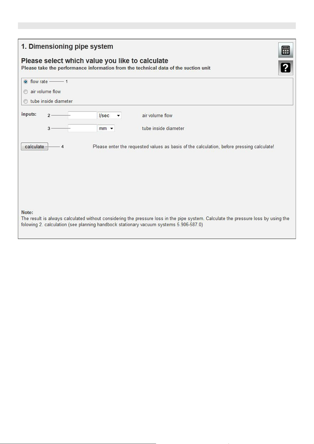
9.1.1 Modes of calculation
Calculation of the air speed
1 Selection "flow rate"
2 Input field "Air volume flow"
3 Input field "Inner pipe diameter"
4 Button "Calculate"
Fill in input fields with relevant values.
Press the "Calculate" button.
The value of the air speed is displayed.
10 English 5.906-587.0 Rev. 00 (05/14)
Page 11
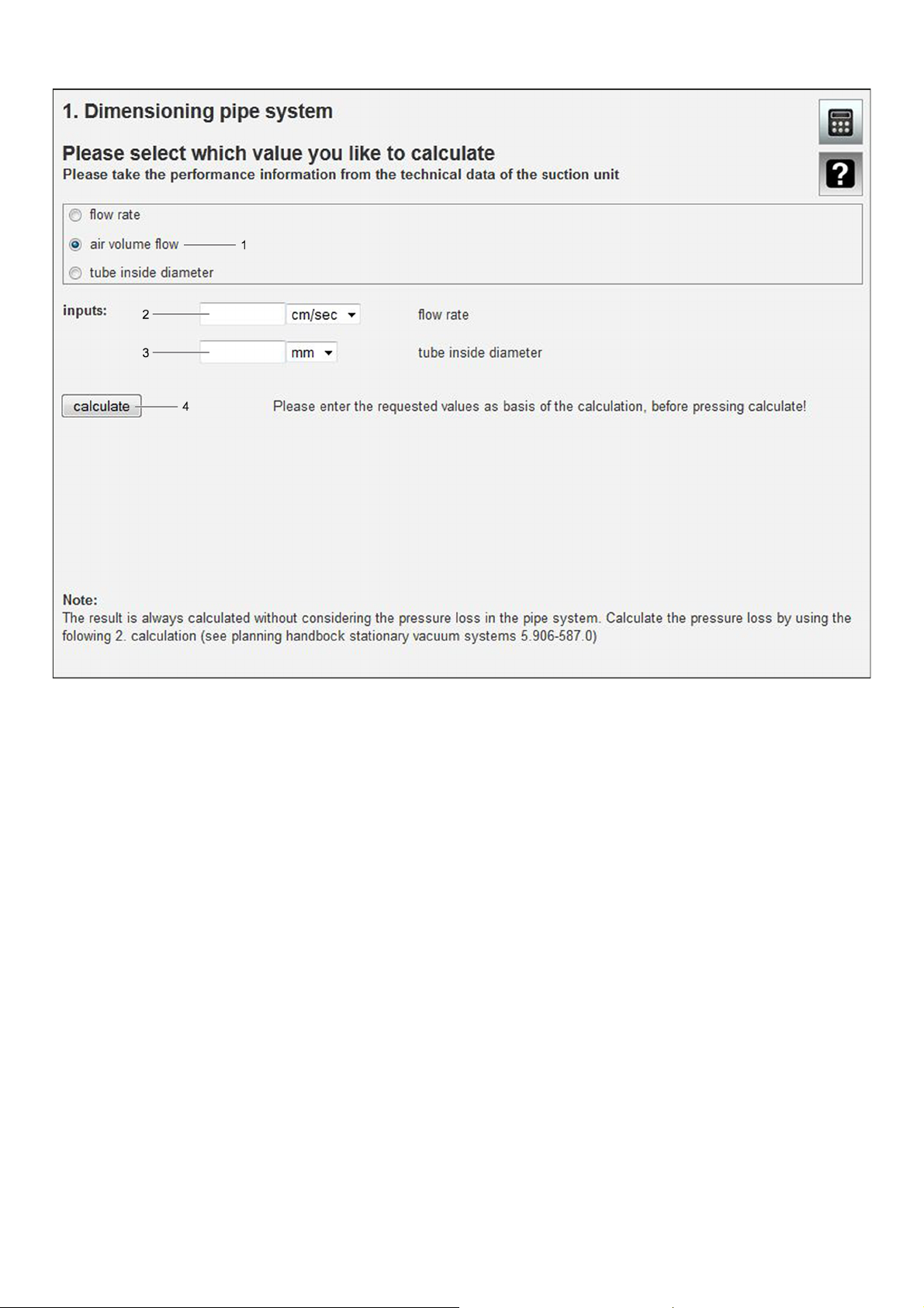
Calculation of the air volume flow
1 Selection "Air volume flow"
2 Input field "flow rate"
3 Input field "Inner pipe diameter"
4 Button "Calculate"
Fill in input fields with relevant values.
Press the "Calculate" button.
The value of the air volume flow is displayed.
English 5.906-587.0 Rev. 00 (05/14) 11
Page 12

Calculation of the inner pipe diameter
1 Selection "Inner pipe diameter"
2 Input field "flow rate"
Depending on the material (see tabular values)
3 Input field "Air volume flow"
Depending on the suction performance from the technical data sheet of the selected vacuum cleaner
4 Button "Calculate"
Fill in input fields with relevant values.
Press the "Calculate" button.
The value of the inner pipe diameter is displayed.
12 English 5.906-587.0 Rev. 00 (05/14)
Page 13
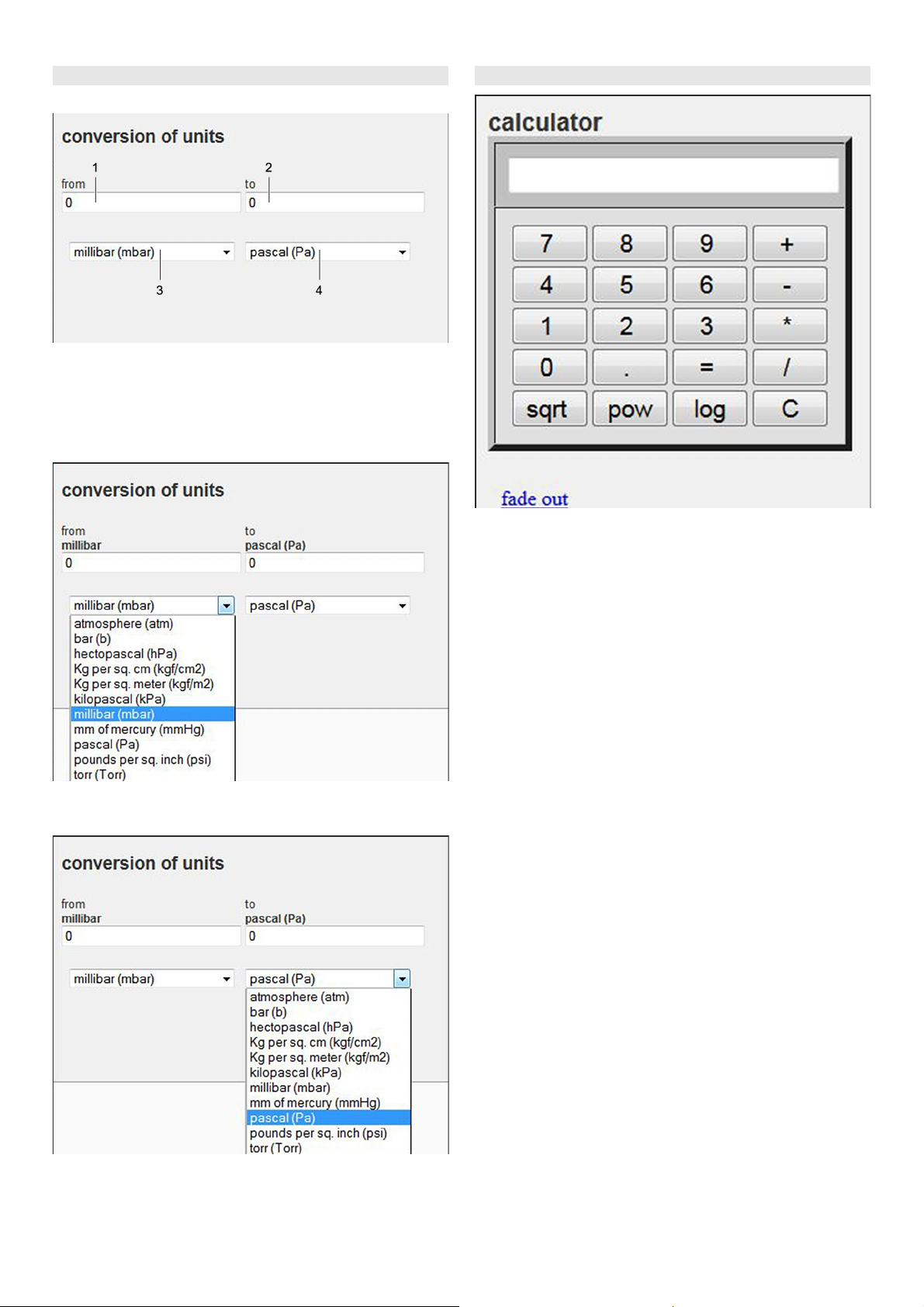
9.1.2 Conversion of units 9.1.3 Calculator
Overview
1 Input field convert value "from"
2 Display field convert value "into"
3 Selection of the units "from"
4 Selection of the units "into"
Convert units "from"
Auxiliary tool for the calculation of various values.
Overview of the units
Convert units "into"
Overview of the units
Select unit "from".
Select unit "into".
Enter the value into the input field, the conversion value
is automatically shown in the display field.
English 5.906-587.0 Rev. 00 (05/14) 13
Page 14
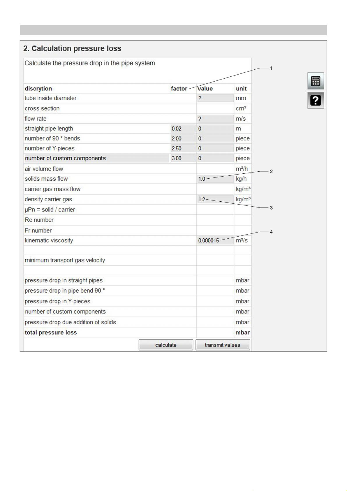
9.2 Calculation tool calculation of the pressure loss
1 Loss coefficient or also pressure loss coefficient, pres-
sure loss coefficient, drag coefficient is denominated
with factor here.
2 The mass flow rate indicates the mass of a medium that
moves through a cross section within a period of time.
The mass flow rate is also referred to as flow rate. As a
standard, it can be calculated with 1.0 here.
3 Air is the carrier gas.
Under standard conditions (temperature 20 °C and air
pressure 1013 mbar) the density of air is ~1.2 kg/m³.
4 The kinematic viscosity describes the relationship be-
tween dynamic viscosity and consistency.
Under standard conditions it is always 0.000015 m³/s.
14 English 5.906-587.0 Rev. 00 (05/14)
Page 15
10 Calculation of the pressure loss
In an ideal line network no losses would occur and the necessary suction unit could be determined with the two parameters air speed and volume flow. In the real line
network, however, losses are created due to resistances
and turbulences. These must be calculated as pressure
losses in the pipeline network in order to determine the required suction performance.
With branched pipelines only the way that causes the
greatest pressure loss (main run) must be determined. For
the calculation of the pressure loss the overall length is divided in sections with the same air quantity (volume flow)
and the same diameter.
A Section 20 m pipeline
B Section 5 m pipeline
C Section 10 m hose
In the individual sections the pressure loss is calculated individually and then added up to the overall pressure loss.
When calculating the overall pressure loss it must be observed which vacuuming points are operated simultaneously.
For the determination of the pressure differences per section the branch lines do not need to be calculated as they
are not relevant for the overall pressure loss of the system.
Branch lines must be closed if they are not in operation
(e.g. with sliders, caps, etc.) so that no false air (see Chapter "Use and setting of the false air valve") is sucked out.
Note
A security of 10 to 20% should be present as the volume
flows can not always be adjusted in the way they have
been calculated and to cover imponderables.
English 5.906-587.0 Rev. 00 (05/14) 15
Page 16

10.1 Pressure loss calculation with the calculation tool
1 Button "Calculate"
2 Button "Adopt value"
If all relevant data has been entered, the pressure loss
of the section can be calculated by pressing the calculate button.
With the "Adopt value" button the value can be loaded
into a cache. The cache automatically adds up the
adopted values.
When all sections of the main run are calculated, the
overall pressure loss is fixed.
16 English 5.906-587.0 Rev. 00 (05/14)
Page 17

10.2 Addition of the sections
1 "Reset" button
2 "Print" button
With the "Reset" button all data is deleted.
An overview can be printed via the "Print" button.
10.3 Alignment with vacuum cleaner characteristic
The overall pressure loss is aligned with the vacuum
cleaner characteristic to determine the actual volume flow.
In the shown example, an overall pressure loss of 27 mbar
was reached. With this value the volume flow of the vacuum cleaner is still 468 m³/h.
It must be checked with the calculation tool which air
speed is reached with this volume flow and the given pipe
diameter. If it is below the required value, either a vacuum
cleaner with more power must be chosen or the pipeline
must be redesigned.
English 5.906-587.0 Rev. 00 (05/14) 17
Page 18

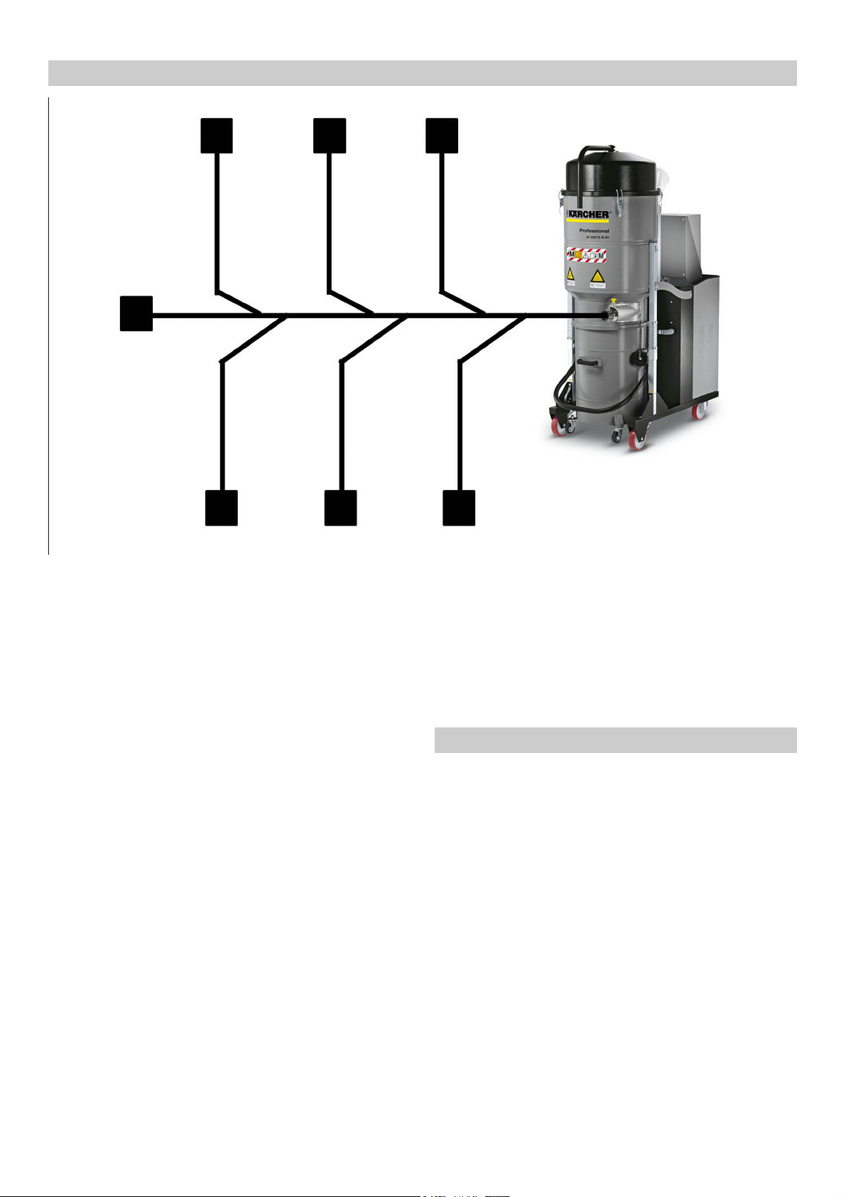
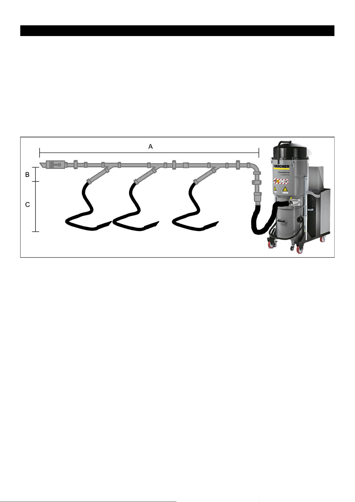
11 Sample calculation for the dimensioning of the vacuum cleaner
In this example calculation, a suction unit for a shop with 3
work stations is to be designed. The system is to be designed in a way that 2 vacuuming points can be operated
in parallel respectively.
Plastic granules are to be vacuumed up.
A Section: DN 80, 25 m, 3x Y-pieces, 2x 90° bends
B Section: DN 60, 5 m
C Section: DN 50, 5 m suction hose
Note
If they are not in operation, all branch lines are shut off by
means of a slide or a flap. At the end of the collecting pipe
(section A) a false air valve (see setting false air valve)
must be installed as the volume flow is pending there.
11.1 Step 1
The total volume flow of all simultaneously operated vacuuming points is calculated for the calculation of the air
speed first.
Note
The air speed results from the available power of the vacuum cleaner (technical data), the number of vacuuming
points that are to be operated in parallel and the inner pipe
diameter of the line.
By means of the calculation tool a max. pipe diameter of
62 mm in the side arm is calculated from the volume flow
250 m³/h and the speed 23 m/s.
The closest diameter in the pipeline programme is DN 60.
As two vacuuming points are operated in parallel, there is
a max. volume flow of 2 x 250 m³/h in the collecting pipe.
For this the calculated pipe diameter with 87.68 mm (with
23 m/s and 500 m3/h) is DN 80.
11.3 Step 3
Identification of the main run in the pipeline system: Main
run is the way that causes the greatest pressure loss.
Example:
IV 100/55 as per technical data sheet 139l/s, that equals
500 m³/h (calculated with the calculation tool).
With 2 vacuuming points the following applies:
Volume flow per vacuuming point:
500 m³/h / 2 vacuuming points = 250 m³/h per vacuuming
point.
Available volume flow per vacuuming point = 250 m³/h.
11.2 Step 2
Now the maximum pipe diameter is calculated under consideration of the air speed.
Note
Determination of the pipe diameter by matching the available pipe sizes with the air speed required for the material.
As per the table in Chapter "Air speed", plastic granules Ø
2-3 mm require an air speed of 20-23 m/s.
Main run shaded in red.
11.4 Step 4
Calculation of the air speed in the individual sections of the
main run by means of the calculation tool.
Example:
Section
1 DN 80 500m³/h 27.63 m/s
2 DN 60 250m³/h 24.56 m/s
3 DN 50 250m³/h 35.37 m/s
Suction
hose
Volume
flow rate
Flow speed
18 English 5.906-587.0 Rev. 00 (05/14)
Page 19

11.5 Step 5
Calculation of the pressure losses in the sections:
Note
All sections together reveal the entire pressure loss plus
10-20% security.
Example:
Section Suction hose LengthComponent Flow speed Pressure loss
1 DN 80 25 m 3x Y-pieces
2x 90° bends
2 DN 60 5 m 24.56 m/s 6.03 mbar
3 DN 51 5 m 1x custom component
(Suction hose)
110.94 mbar + 15% security addition = ~128 mbar
27.63 m/s 32.63 mbar
35.37m/s 18.01 mbar
11.6 Step 6
Alignment of the overall pressure loss with the vacuum
cleaner characteristic.
Example:
With a pressure loss performance of 128 mbar, a volume
flow of ~330 m³/h remains with IV 100/55.
English 5.906-587.0 Rev. 00 (05/14) 19
Page 20

11.7 Step 7
11.9 Step 9
Recalculation of the volume flow per vacuuming point.
Example:
IV 100/55 as per technical data sheet with a pressure loss
of 128 mbar = ~330 m³/h.
With 2 vacuuming points the following applies:
Volume flow per vacuuming point:
330m³/h / 2 vacuuming points = 165 m³/h per vacuuming
point.
11.8 Step 8
Calculation of the actual flow velocities in the sections and
subsequent alignment with the required air speed of the
application, in the example 20-23 m/s.
Example:
Section
1 DN 80 330m³/h 18.24m/s
2 DN 60 165m³/h 16.21 m/s
3 DN 50 165m³/h 23.34 m/s
In the sections 1 and 2 the required air speed of the example cannot be reached. Thus, a more powerful vacuum
cleaner must be used.
Note
In this example a reduction of the pipe diameter would increase the flow velocities in the relevant sections, however, it would also reduce the dissipation power and thus the
achievable volume flow.
Suction
hose
Volume
flow rate
Flow speed
The recalculation takes place analogously to the previous
example.
Step 1
The total volume flow of all simultaneously operated vacuuming points is calculated for the calculation of the air
speed first.
Example:
IV 100/75 as per technical data sheet 153l/s, that equals
550 m³/h according to the calculation tool.
With 2 vacuuming points the following applies:
Volume flow per vacuuming point:
550m³/h / 2 vacuuming points = 275 m³/h per vacuuming
point.
Available volume flow per vacuuming point = 275 m³/h
Step 2
Now the maximum pipe diameter is calculated under consideration of the flow velocities.
Example:
As per the table in Chapter "Air speed" plastic granules Ø
2-3 mm require a air speed of 20-23 m/s. By means of the
calculation tool a max. pipe diameter of 91 mm is calculated for section 1 from a volume flow of 550 m³/h and the
speed of 23 m/s. In due consideration of the air speed the
next smaller diameter is chosen from the pipeline programme. In the example DN 80.
Step 3
Calculation of the flow velocities in the individual sections
of the main run by means of the calculation tool.
Example:
Section
1 DN 80 500 m³/h 30.39 m/s
2 DN 60 275 m³/h 27.02 m/s
3 DN 50 275 m³/h 38.90 m/s
Suction
hose
Volume
flow rate
Flow speed
20 English 5.906-587.0 Rev. 00 (05/14)
Page 21

Step 4
Calculation of the pressure losses in the sections:
Section Suction hose LengthComponent Flow speed Pressure loss
1 DN 80 25 m 3x Y-pieces
2x 90° bends
2 DN 60 5 m 27.02 m/s 7.30 mbar
3 DN 51 5 m 1x custom component
(Suction hose)
68.43 mbar + 15% security addition = ~79 mbar
Step 5
Alignment with characterisitc.
Example:
With a pressure loss performance of 79 mbar, a volume
flow of ~420 m³/h remains with IV 100/75.
30.39 m/s 46.13 mbar
38.90 m/s 15.00 mbar
English 5.906-587.0 Rev. 00 (05/14) 21
Page 22

Step 6
Recalculation of the volume flow per vacuuming point.
Example:
With a pressure loss performance of 79 mbar, a volume
flow of ~420 m³/h remains with IV 100/75.
Volume flow per vacuuming point:
420m³/h / 2 vacuuming points = 210 m³/h per vacuuming
point.
Step 7
Calculation of the actual flow velocities in the sections and
subsequent alignment with the necessary air speed of the
application:
Example:
Section
1 DN 80 420 m³/h 23.21 m/s
2 DN 60 210 m³/h 20.63 m/s
3 DN 50 210 m³/h 29.71 m/s
With the IV 100/75 the required air speed can be reached
in all sections.
Suction
hose
Volume
flow rate
Flow speed
22 English 5.906-587.0 Rev. 00 (05/14)
Page 23

12 Basics of the system installation
12.1 Overview module components
1 Outlet tube
2 Clack valve / false air flap
3 Control cable
4 Tensioning ring
5 Y-branch
6 Fastening clamp
7 Pipe bend
8 Control / distribution box
9 Connection hose DN 70
10 Connection piece hose
11 Cone piece
12 Gate valve electrical or pneumatic
13 Remote control
English 5.906-587.0 Rev. 00 (05/14) 23
Page 24

12.2 Examples for correct and incorrect system installation
12.3 Examples for the correct and incorrect branchings in the pipeline network
24 English 5.906-587.0 Rev. 00 (05/14)
Page 25

13 Use and setting of the false air valve
Note
A false air valve or a bypass valve is a valve that opens at
a certain adjustable negative pressure in order to be able
to vacuum with a constant air volume.
A Induction pipe
B False air / bypass valve
C Silencer
Suction performance per ~ 250 m³/h per vacuuming
point
1 Locknut
The adjustment is made via the lock nut. The valve is to be
adjusted in a way that it does not open with all vacuuming
points operated in parallel yet.
Vacuum cleaner, performance e.g. 500 m³/h
False air valve closed
Suction performance ~ 250 m³/h
Vacuum cleaner, performance e.g. 500 m³/h
False air valve open
~ 250 m³/h via the false air valve. This way it is ensured
that the flow rate in the suction hose is almost the same as
during vacuuming with two vacuuming points.
English 5.906-587.0 Rev. 00 (05/14) 25
Page 26

14 Installation instructions for tension ring connections with flanged sealing ring
QUICK CONNECT© tension ring
Mount the flanged sealing ring onto one of the flanged
edges.
The flanged sealing ring can be slightly pulled during
mounting, however, do not overstretch it.
Flanged sealing ring mounted.
Note
The corrugated side of the flanged sealing ring must point
towards the connection pipe part.
Attach tension ring.
Hold up opposite pipe to slide one tension ring half over
the flanged edges.
Push the second tension ring half over the flanged edg-
es.
Place the clamp over the locking hook and close the
handle.
Note
– With QUICK CONNECT the tension ring half without
the clip-lock must be mounted first.
– When sliding on the tension ring, ensure that the pipe
parts do not show an offset and the flanged sealing ring
is not displaced.
– With horizontally routed lines in which condensate is
formed the joint of the flanged sealing ring and also the
joinings of the tension ring halves should preferably not
be positioned at the lowest point.
26 English 5.906-587.0 Rev. 00 (05/14)
Page 27

CAUTION
– When closing the tension ring, the flanged sealing ring
must not form a loop. In order to facilitate the closing
process, the tensioning screw at the joint can be
screwed back if necessary.
– Then the tensioning screw must be tightened to prevent
accidental unlocking of the joint (e.g. in case of vibrations) and to increase the tightness.
– For explosion-proof connections up to 3 bar overpres-
sure a tightening torque of 10 Nm is required.
Note
It is advisable to completely disassemble the tension ring
first. However, it can also be mounted analogously to the
QUICK CONNECT© tension ring by completely loosening
one screw only.
Tension ring two-part
1 Clamping shoe projecting
2 Clamping shoe recessed
Push the second tension ring half onto the flanged edg-
es.
Insert screws and evenly tighten them alternately on
each side.
CAUTION
– The flanged sealing ring must not form any loops.
– With explosion-proof connections up to 3 bar overpres-
sure a tightening torque of 25 Nm is required.
– For all listed tension rings a hexagon cap screwdriver
with 6 mm width across flats is required.
English 5.906-587.0 Rev. 00 (05/14) 27
Page 28

15 Producing a flanged edge
15.1 Information concerning border
sealings
Measure the fitting length and transfer it to the pipe (fit-
ting length + 7 mm for the flanged edge).
Set the flanging device with the edge to this length and
mark the cutting line over the circumference of the pipe.
Push back the flanging device and cut the pipe to length
using a cutoff wheel or a saw.
Profile for 1 mm
in:
EPDM conductive
Rubber quality Colour Temperature
NBR (nitrile rubber) Grey 100 ?
EPDM (Keltan) Black
For connections of:
– 2 mm and 2 mm thick pipe parts
– 2 mm and 1.5 mm thick pipe parts
– 2 mm and 1 mm thick pipe parts*
– 1.5 mm and 1.5 mm thick pipe parts*
* In case of high requirements on the tightness of the connection, the thicker flanged sealing ring should be used for
1 mm pipework.
Profile for 2 mm
in:
NBR, silicone,
Viton
(conductive)
Profile for 2 mm
in:
EPDM conductive
120 ?
Then clamp the pipe into the flanging device so that it
projects 7 mm.
Turn up the projecting hose using a hammer until an
even, sharp-edged flanged edge has been created.
28 English 5.906-587.0 Rev. 00 (05/14)
Page 29

16 General mounting instructions for the creation of tight connections
Note
Border sealings made of NBR (nitrile rubber) are suitable
for the use in the food sector (FDA approval available).
In the area of explosive gases and dusts the earthing of all
pipeline parts must be checked after the installation.
Conductive border sealings made of EPDM do not make
conductive connections with primed pipe parts due to the
insulating paint.
– Refinish damaged flanged edges (e.g. realign).
– Remove irregularities from the flanged edge (e.g. paint
bubbles, zinc drops).
– The weld seam at the flanged edge must not be ripped.
– Do not reuse damaged border sealings.
– The pipework must be laid free of tension.
– The flanged sealing ring must not form any loops during
the tension ring installation.
– Horizontally installed lines must be supported approx.
every 4 m. If there are several short pipe parts in the
line, the distance of the support points should be reduced. The same applies in case of additional loads.
Outgoing lines must be secured in a way that they do
not create a torque in the main line.
After installation, remove the transport lock by means
of the pliers.
The joints are permanently pressed onto both pipe
parts by means of spring force.
16.1 Installation instructions earthing bridge
CAUTION
With primed pipe parts the contact points must be freed
from the primer! A possible corrosion protection must be
conductive. (e.g. zinc spray).
CAUTION
Upon fastening the earthing bridge the tension ring screw
must be secured against unscrewing.
Screw the earthing bridge on the projecting thread of
the tension ring screw.
Tighten the earthing bridge with a torque of 8 to 10 Nm.
Note
– A thread projection of 8 mm suffices to secure the
earthing bridge.
– Required tools: Pliers and wrench SW 13 (better ratchet).
Check the spring tension by moving the joints after in-
stallation.
Should the spring force not suffice at extreme junctions, it
can be increased by the installation of one or two short
springs on the joints.
English 5.906-587.0 Rev. 00 (05/14) 29
Page 30

17 Commissioning remote control
17.1 Selecting the setup location
Make sure that a suitable power supply is available in the
immediate vicinity (see technical data of the vacuum
cleaner).
Note
– The scope of delivery does not include any fastening
material!
– The fastening material must be adapted to the local
consistency and condition of the wall and must be ordered separately.
– You will need:
4 x suitable fasteners with a load of 0.5 KN per dowel
and a pin diameter of max. 6 mm.
17.2 Installation
Remove the remote control from its packaging and
check for completeness.
Mount remote control onto a suitable wall.
Connect the electric supply line via a CEE plug (DIN
49462/63) or a terminal box. (This work must be performed by a skilled and authorised electrician)
Mount and connect the starting devices (push button,
switch, coin acceptor, etc.)
Set the parameters.
17.3 Functional description
– Remote control cabinet (No. 4.812-236.0) for the con-
nection of vacuum cleaners up to max. 7.5 KW via 230V,
CEE 16A 400V and CEE 32A 400V connections associated with four external start options.
A soft start can be optionally installed.
– Via the SPS menu various switching types can be select-
ed.
– Inching:
Press 1 x, vacuum cleaner is running, lamp is flashing.
Press again, the vacuum cleaner switches off and the
lamp goes out.
– Inching:
Press 1 x, vacuum cleaner is running, lamp is flashing.
After the set time under the parameters B20 to B30, the
vacuum cleaner switches off.
– Switching operation:
The vacuum cleaner runs as long as the switch is on
"ON".
– The "Lamp" signal can also be used for switching valves
or the like, for this purpose the parameters B129 to B135
must be changed accordingly.
– Via the parameter B33 a maximum run time can be
specified to avoid cycling in case of a failure to switch off.
– Via the parameter B137 it is selected whether a soft start
is installed or not.
– In order to ensure that after closing all valves or slides
the suction pipe was sucked free, an after-running time
can be set via the parameter B143.
CAUTION
When using the "after-running time" function, a false air
flap must be installed to avoid an excessive vacuum in the
system.
A detailed description can be found in the operating instructions of the remote control 5.965-276.0.
17.4 Parameter IV vacuum cleaner control
B20 With preselection "pushbutton" run time vacuum
cleaner station 1
B 28 With preselection "pushbutton" run time vacuum
cleaner station 2
B 29 With preselection "pushbutton" run time vacuum
cleaner station 3
B 30 With preselection "pushbutton" run time vacuum
cleaner station 4
B 33 Maximum run time vacuum cleaner all stations
are switched off
B 49 To FB 1 = 0: Button 1: Switch
B 50 To FB 2 = 0: Button 1: Switch
B 51 To FB 3 = 0: Button 1: Switch
B 52 To FB 4 = 0: Button 1: Switch
B 65 Reset daily operating hours counter:
Can be reset via password (1234) or button <and -> held down for 2 seconds.
B 129 Lamp connected
station 1
B 131 Lamp connected
station 2
B 133 Lamp connected
station 3
B 135 Lamp connected
station 4
B 137 Soft start yes / no 1 = soft
B 143 After-running time vacuum cleaner
1= lamp 0 = valve
(no flashing
with run time)
1= lamp 0 = valve
(no flashing
with run time)
1= lamp 0 = valve
(no flashing
with run time)
1= lamp 0 = valve
(no flashing
with run time)
0 = no soft
start installed
start installed
30 English 5.906-587.0 Rev. 00 (05/14)
Page 31

18 Annex 1 - Questionnaire central vacuuming systems 5.906-589.0
18.1 Customer details
Company name Date
Address Telephone
Customer number Fax
Contact person E-mail
Industry
18.1.1 Preface
When selecting an industrial cleaning machine, two basic things have priority: For one thing the zoning in which the
appliance is to be set up later on, and for another thing the type of the vacuumed material. A certification as per ATEX,
for example, is not always sufficient for vacuuming up combustible or toxic dusts. That is why a good spadework upon
enquiring the application site is of great importance. Thus, please fill in this enquiry as detailed as possible. Eventually,
the responsibility, however, always rests with the user or operator.
18.2 Checklist product
Product description - vacuumed material
toxic
allergic
abrasive
combustible/explosive
caustic
hygroscopic
others
Particle size min mm
max mm
Temperature °C
Product moisture %
Specific weight kg/m
3
Quantity per shift/day/hour / /
English 5.906-587.0 Rev. 00 (05/14) 31
Page 32

18.3 Checklist system
Location of the vacuum
cleaner
Size of the plant room Temperature at the location °C
Operating time of the plant Number of vacuuming points
Number of vacuuming
points operated in parallel
Vacuuming height m Length suction hose m
Diameter suction hose
Product discharge
Automatic Manual Flap pneum. valve Flat slide valve
Filter cleaning
Automatic Manual
Main filter
Filter class
Hepa Class
Dust class
MH
Control
Filling level detector / switch-off yes no
Piping length m
Switch cabinet provided by the
customer
Switching type Buttons Switch Slide with switch Hook
Preliminary filter
Type
Volume
Connections
Supplementary
equipment
ATEX-zone yes no which
Accessories
Nozzles
Support
Hose type PU PVC Steel with PU PU light
yes no Number remote controls:
32 English 5.906-587.0 Rev. 00 (05/14)
Page 33

18.4 Other information
English 5.906-587.0 Rev. 00 (05/14) 33
Page 34

19 Annex 2 - Motor characteristics
34 English 5.906-587.0 Rev. 00 (05/14)
Page 35

20 Annex 3 - Pipe programme
Welded pipes Nominal
length
The pipe length and the diameter DN are nominal dimensions, the actual length can differ.
Ø60
2000 zinc-coated 57 1,5 4,34 6.880-017.0
1000 zinc-coated 57 1,5 2,10 6.880-025.0
500 zinc-coated 57 1,5 1,03 6.880-033.0
200 zinc-coated 57 1,5 0,45 6.880-041.0
2000 stainless steel 57 1,5 4,50 6.880-021.0
1000 stainless steel 57 1,5 2,24 6.880-029.0
500 stainless steel 57 1,5 1,03 6.880-037.0
200 stainless steel 57 1,5 0,45 6.880-045.0
Ø80
2000 zinc-coated 78 1 4,50 6.880-018.0
1000 zinc-coated 78 1 2,15 6.880-026.0
500 zinc-coated 78 1 1,14 6.880-034.0
200 zinc-coated 78 1 0,50 6.880-042.0
50 zinc-coated 78 1 0,12 6.880-049.0
Material Ød S WeightkgPart no.
2000 stainless steel 78 1 3,89 6.880-022.0
1000 stainless steel 78 1 1,94 9.982-619.0
500 stainless steel 78 1 0,97 9.982-620.0
200 stainless steel 78 1 0,41 9.982-621.0
50 stainless steel 78 1 0,12 6.880-052.0
Ø100
2000 zinc-coated 99 1 5,60 6.880-019.0
1000 zinc-coated 99 1 2,90 9.982-654.0
500 zinc-coated 99 1 1,40 6.880-035.0
200 zinc-coated 99 1 0,65 9.982-655.0
50 zinc-coated 99 1 0,15 6.880-050.0
2000 stainless steel 99 1 4,97 6.880-023.0
1000 stainless steel 99 1 2,48 6.880-031.0
500 stainless steel 99 1 1,24 6.880-039.0
200 stainless steel 99 1 0,52 6.880-047.0
50 stainless steel 99 1 0,15 6.880-053.0
Ø120
2000 zinc-coated 119 1 6,60 6.880-020.0
1000 zinc-coated 119 1 3,60 9.982-688.0
500 zinc-coated 119 1 1,70 9.982-689.0
200 zinc-coated 119 1 0,75 6.880-044.0
50 zinc-coated 119 1 0,18 6.880-051.0
2000 stainless steel 119 1 5,96 6.880-024.0
1000 stainless steel 119 1 2,97 6.880-032.0
English 5.906-587.0 Rev. 00 (05/14) 35
Page 36

Welded pipes Nominal
length
500 stainless steel 119 1 1,49 6.880-040.0
200 stainless steel 119 1 0,63 6.880-048.0
50 stainless steel 119 1 0,18 6.880-054.0
Material Ød S WeightkgPart no.
Flanging device ØA Weight
kg
Powder-coated flanging device with a welded
on angle. For attaching a flanged edge to a
pipe end.
Weld-on ends Material Ød L S WeightkgPart no.
Weld-on ends, flanged on one side Ø60
Ø60
60 3,10 6.880-161.0
Ø80
80 3,30 6.880-162.0
Ø100
103 3,60 6.880-163.0
Ø120
120 4,70 6.880-164.0
zinc-coated 57 55 1,5 0,13 6.880-055.0
Ø80
zinc-coated 77 55 1,5 0,12 6.880-056.0
Ø100
Part no.
zinc-coated 99 55 2,0 0,30 6.880-057.0
Ø120
zinc-coated 119 55 2,0 0,36 6.880-058.0
Insertion pipes Material Ød ØB S WeightkgPart no.
Nominal length 500 mm. Slide-in pipe for fitting
length compensation. For constructional reasons an explosion pressure shock resistance
(up to 3 bar) does not apply for a slide-in pipe.
Ø60
stainless steel 57 54 1,5 1,40 6.880-059.0
Ø80
stainless steel 78 75 1,0 0,90 6.880-060.0
Ø100
stainless steel 100 96 1,0 1,17 6.880-061.0
Ø120
stainless steel 120 116 1,0 1,41 6.880-062.0
36 English 5.906-587.0 Rev. 00 (05/14)
Page 37

Jointring Material Ød ØA WeightkgPart no.
Jointrings for sealing insertion pipes at 1 to
3 mm wall thickness.
Keltan (EPDM*/**) -30°C to +120°C; black.
Pipe bends Angle Material Ød R S WeightkgPart no.
Pipe bends with R=2D made of drawn halfshells. In use this means a flow optimisation
and a larger wear resistance.
Ø60
EPDM 7 53 0,01 6.880-072.0
Ø80
EPDM 9 68 0,02 6.880-073.0
Ø100
EPDM 9 87 0,02 6.880-074.0
Ø120
EPDM 9 106 0,03 6.880-075.0
Ø60
30° zinc-coated 57 120 1,5 0,25 6.880-082.0
45° zinc-coated 57 120 1,5 0,40 6.880-090.0
90° zinc-coated 57 120 1,5 0,75 6.880-098.0
30° stainless steel 57 120 1,5 0,25 6.880-086.0
45° stainless steel 57 120 1,5 0,40 6.880-094.0
90° stainless steel 57 120 1,5 0,75 6.880-102.0
Ø80
15° zinc-coated 78 130 1 0,10 6.880-076.0
30° zinc-coated 76 160 1 0,35 6.880-083.0
45° zinc-coated 76 160 1 0,50 6.880-091.0
90° zinc-coated 76 160 1 0,95 6.880-099.0
15° stainless steel 78 130 1 0,10 6.880-079.0
30° stainless steel 76 160 1 0,35 6.880-087.0
45° stainless steel 76 160 1 0,50 6.880-095.0
90° stainless steel 76 160 1 0,95 9.982-623.0
Ø100
15° zinc-coated 100 130 1 0,10 6.880-077.0
30° zinc-coated 99 200 1 0,60 6.880-084.0
45° zinc-coated 99 200 1 0,85 6.880-092.0
90° zinc-coated 99 200 1 1,55 6.880-100.0
15° stainless steel 100 130 1 0,10 6.880-080.0
30° stainless steel 99 200 1 0,60 6.880-088.0
45° stainless steel 99 200 1 0,85 6.880-096.0
90° stainless steel 99 200 1 1,55 6.880-104.0
Ø120
15° zinc-coated 120 155 1 0,15 6.880-078.0
30° zinc-coated 119 240 1 0,80 6.880-085.0
45° zinc-coated 119 240 1 1,15 6.880-093.0
90° zinc-coated 119 240 1 2,20 6.880-101.0
English 5.906-587.0 Rev. 00 (05/14) 37
Page 38

Pipe bends Angle Material Ød R S WeightkgPart no.
15° stainless steel 120 155 1 0,15 6.880-081.0
30° stainless steel 119 240 1 0,80 6.880-089.0
45° stainless steel 119 240 1 1,15 6.880-097.0
90° stainless steel 119 240 1 2,20 6.880-105.0
Pipe bow 90° Material Part no.
R=500, Ø d=80. stainless steel 6.880-106.0
Fork piece 45° Material G H L S WeightkgPart no.
Ø60
zinc-coated 115 115 145 1,5 0,60 6.880-107.0
stainless steel 115 115 145 1,5 0,60 6.880-111.0
Ø80
zinc-coated 123 137 160 1,5 0,75 6.880-108.0
stainless steel 123 137 160 1 0,50 6.880-112.0
Ø100
zinc-coated 177 176 215 1,5 1,15 6.880-109.0
stainless steel 177 176 215 1 0,77 6.880-113.0
Ø120
zinc-coated 187 185 240 1,5 1,50 6.880-110.0
stainless steel 187 185 240 1 1,00 6.880-114.0
Fork piece 30° Material G H L S WeightkgPart no.
Ø60
zinc-coated 170 170 200 1,5 0,85 6.880-115.0
38 English 5.906-587.0 Rev. 00 (05/14)
stainless steel 170 170 200 1,5 0,57 6.880-122.0
Ø80
zinc-coated 209 216 240 1,5 1,32 6.880-116.0
stainless steel 209 216 240 1 0,88 6.880-124.0
Ø100
zinc-coated 262 216 300 1,5 1,70 6.880-120.0
stainless steel 262 216 300 1 1,33 6.880-127.0
Page 39

Conical fork pieces 30° Material ØC ØE=ØFG H WeightkgPart no.
Ø80/60/60
zinc-coated 78 57 170 170 0,95 6.880-117.0
stainless steel 78 57 170 170 0,95 6.880-123.0
Ø100/80/80
zinc-coated 100 78 237 236 1,25 6.880-118.0
stainless steel 100 78 237 236 0,25 6.880-125.0
Ø100/100/80
zinc-coated 100 100 239 248 1,35 6.880-119.0
stainless steel 100 100 239 248 1,35 6.880-126.0
Ø120/120/80
zinc-coated 120 120 256 258 1,50 6.880-121.0
stainless steel 120 120 256 258 1,50 6.880-128.0
Y-branch Material Ød A B S WeightkgPart no.
Ø80
zinc-coated 77 40 120 1,5 0,80 6.880-129.0
stainless steel 78 40 120 1 0,45 6.880-132.0
Ø100
zinc-coated 100 50 120 1,5 1,00 6.880-130.0
stainless steel 100 50 120 1 0,60 6.880-133.0
Ø120
zinc-coated 120 50 150 1,5 1,50 6.880-131.0
stainless steel 120 50 150 1 0,70 6.880-134.0
Cone pieces Material ØA ØB L S WeightkgPart no.
Ø60/80
stainless steel 57 77 60 1,5 0,17 6.880-138.0
Ø80/100
zinc-coated 78 100 100 1,5 0,35 6.880-135.0
stainless steel 78 100 100 1,5 0,35 6.880-139.0
Ø80/120
zinc-coated 78 120 80 1,5 0,35 6.880-136.0
stainless steel 78 120 80 1,5 0,35 6.880-140.0
Ø100/120
zinc-coated 100 120 60 1 0,30 6.880-137.0
stainless steel 100 120 60 1 0,30 6.880-141.0
English 5.906-587.0 Rev. 00 (05/14) 39
Page 40

Hose connecting pieces Material Ød B F L WeightkgPart no.
Wall thickness 1 mm Ø60
stainless steel 57 60 80 0,02 6.880-144.0
Ø80
zinc-coated 78 78 15 88 0,02 6.880-142.0
stainless steel 78 78 15 88 0,02 9.982-624.0
Ø100
zinc-coated 100 95 15 100 0,25 6.880-143.0
stainless steel 100 95 15 100 0,25 9.982-661.0
Outlet pipes 45° with bird screen Material Ød A L WeightkgPart no.
Bird screen
Mesh 20 x 20 x 20 mm.
False air / bypass valve Nominal Ø Part no.
False air / bypass valve with flanged edge for
the connection to a pipe end DN100.
Ø80
zinc-coated 78 280 200 0,90 6.880-147.0
stainless steel 78 280 200 0,90 6.880-150.0
Ø100
zinc-coated 100 300 200 1,20 6.880-148.0
stainless steel 100 300 200 1,20 6.880-151.0
Ø120
zinc-coated 120 320 200 1,50 6.880-149.0
stainless steel 120 320 200 1,50 6.880-152.0
100 9.985-584.0
Cleaning pipe Material Ød A L WeightkgPart no.
Sealing ring Neoprene (CR), -30 max. +90 °C. Ø80
zinc-coated 77 80 200 1,05 6.880-153.0
stainless steel 77 80 200 1,05 6.880-156.0
Ø100
zinc-coated 100 115 200 1,45 6.880-154.0
stainless steel 100 115 200 1,45 6.880-157.0
Ø120
zinc-coated 120 115 200 1,45 6.880-155.0
stainless steel 120 115 200 1,45 6.880-158.0
40 English 5.906-587.0 Rev. 00 (05/14)
Page 41

Quick Connect tension rings, one-piece Material ØA ØB WeightkgPart no.
Quick Connect tension rings without sealing
compound for border sealings with 1 mm and
2 mm pipe parts.
Tension rings one-piece with sealing compound
The one-piece tension rings can also be used
for the connection of 1 mm with 1.5 mm thick
pipe parts.
With the one-piece tension ring installation
knowledge is required.
Ø80
zinc-coated 100 80 0,35 9.982-818.0
stainless steel 100 80 0,35 6.880-003.0
Ø100
zinc-coated 123 103 0,35 9.982-834.0
stainless steel 123 103 0,37 6.880-004.0
Ø120
zinc-coated 143 123 0,40 9.982-843.0
stainless steel 143 123 0,40 6.880-005.0
Material ØA ØB WeightkgPart no.
Ø80
zinc-coated 100 80 0,35 6.880-006.0
Ø100
zinc-coated 123 103 0,37 6.880-007.0
Ø120
zinc-coated 143 123 0,40 6.880-008.0
Tension rings two-piece Material ØA ØB WeightkgPart no.
Two-piece tension ring, e.g. for insertion pipes
with 1 + 2 mm wall thickness with jointrings.
Ø60
zinc-coated 81 60 0,30 9.982-814.0
stainless steel 81 60 0,30 6.880-067.0
Ø80
zinc-coated 101 80 0,31 9.982-817.0
stainless steel 101 80 0,31 6.880-068.0
Ø100
zinc-coated 125 104 0,33 9.982-833.0
stainless steel 125 104 0,33 6.880-069.0
Ø120
zinc-coated 145 124 0,36 9.982-842.0
stainless steel 145 124 0,36 6.880-070.0
English 5.906-587.0 Rev. 00 (05/14) 41
Page 42

Border sealings Material ØA ØB WeightkgPart no.
Border sealings for 1 mm (for QUICK CONNECT tension rings and two-piece tension
rings without seal).
Perbunan (NBR*) -30°C to +100°C; off-white
Keltan (EPDM*/**) -30°C to +120°C; black
*Food grade with FDA conformity
** Electrostatically conductive.
Hexagon cap screwdriver Spanner size Part no.
Hexagon cap screwdriver for tension ring installation.
Ø60
NBR57690,029.982-923.0
EPDM57690,026.880-013.0
Ø80
NBR81930,026.880-010.0
EPDM81930,026.880-014.0
Ø100
NBR 103 115 0,03 9.982-928.0
EPDM 103 115 0,03 6.880-015.0
Ø120
NBR 123 135 0,03 9.982-931.0
EPDM 123 135 0,03 6.880-016.0
56.880-185.0
66.880-186.0
Earthing bridge Material Part no.
Earthing bridge for electrostatic potential
equalization.
stainless steel 6.880-071.0
Useable for the conductive bridging of all tension ring connections with
the two-piece tension ring or the QUICK CONNECT tension ring.
Subsequent installation without welding and drilling possible.
The earthing bridge is attached to one of the screws of the tension ring.
Alternatively the potential equalization can also take place via conductive flanged sealings made of EPDM or with earthing cables.
42 English 5.906-587.0 Rev. 00 (05/14)
Page 43

Pipe clamps wall mount Material ØA B C E WeightkgPart no.
Pipe clamps for wall mount with insulation insert (EPDM, -40 °C – +120 °C).
Use of the pipe clamps only for the absorption
of transverse forces of the pipe.
Pipe clamps ceiling fixture Material ØA E T1 WeightkgPart no.
Ø60
zinc-coated 60 50 100 20x1 0,20 6.880-165.0
stainless
steel
Ø80
zinc-coated 80 64 138 30x2.5 0,70 6.880-166.0
stainless
steel
Ø100
zinc-coated 102 75 138 30x2.5 0,80 6.880-167.0
stainless
steel
Ø120
zinc-coated 123 86 138 30x2.5 0,85 6.880-168.0
stainless
steel
60 50 100 20x1 0,20 6.880-169.0
80 64 138 30x2.5 0,70 6.880-170.0
102 75 138 30x2.5 0,80 6.880-171.0
123 86 138 30x2.5 0,85 6.880-172.0
Pipe clamps for ceiling fixture with insulation insert (EPDM, -40 °C – +120 °C).
Ø60
zinc-coated 60 20x1 – 0,11 6.880-173.0
stainless
steel
Ø80
zinc-coated 80 25x1.5 2,0 0,20 6.880-174.0
stainless
steel
Ø100
zinc-coated 102 25x1.5 2,0 0,24 6.880-175.0
stainless
steel
Ø120
zinc-coated 123 25x1.5 2,0 0,27 6.880-176.0
stainless
steel
60 20x1 – 0,11 6.880-177.0
80 25x1.5 2,0 0,20 6.880-178.0
102 25x1.5 2,0 0,24 6.880-179.0
123 25x1.5 2,0 0,27 6.880-180.0
English 5.906-587.0 Rev. 00 (05/14) 43
Page 44

Beam clamps Material ØA B C E WeightkgPart no.
Beam clamps for fixing pipelines to steel girders (without welding or drilling).
With adjusting screw M10, D=11 mm and width
B=21 mm.
Mounting bracket Material Part no.
Mounting bracket zinc-coated. Load capacity
3.0 kN with 5 mm deformation.
Ø60
zinc-coated 60 50 100 20x1 0,20 6.880-181.0
stainless
steel
zinc-coated 6.880-183.0
60 50 100 20x1 0,20 6.880-182.0
Threaded rods Material Description Part no.
Threaded rods 1000 mm long, DIN 975. stainless steel Threaded rod
M10-St37K-A2E DIN 975
stainless steel Threaded rod
M10-St37K-A2E DIN 975
stainless steel Threaded rod
M12-A2 DIN 975
Stock screw Material Description Part no.
stainless steel Stock screw M 10 x 100 mm 6.880-184.0
stainless steel Stock screw M 12 x 100 mm 6.373-331.0
7.308-507.0
7.307-045.0
7.308-508.0
44 English 5.906-587.0 Rev. 00 (05/14)
Page 45

Hexagon nuts and washers Material Description Part no.
Hexagon nuts DIN 934 zinc-coated Hexagon nut M10 7.311-006.0
zinc-coated Hexagon nut M12 7.311-008.0
stainless steel Hexagon nut M10 7.311-066.0
stainless steel Hexagon nut M12 7.311-071.0
Washers ISO 7090 zinc-coated Washer 10-200HV-A3E 7.312-005.0
zinc-coated Washer 12-200HV-A3E 7.312-008.0
stainless steel Washer 10-A4 7.312-014.0
stainless steel Washer 12-A2 7.312-054.0
Dowel Material Description Part no.
zinc-coated Impact dowel M10 6.373-229.0
zinc-coated Impact dowel M12 6.373-230.0
synthetic
material
synthetic
material
synthetic
material
Squeezing valve incl. installation material Description Part no.
Squeezing valve 9.983-222.0
Quick ventilator 6.413-217.0
Double adapter 6.395-121.0
Solenoid valve NO 24V= 3/2 6.686-149.0
Screw connection angle 1/4", DN6 6.386-764.0
Connection adapter DN6 6.386-860.0
Hose blue PA 6/4 (by the meter) 6.390-963.0
Expansion dowel M6 6.373-224.0
Expansion dowel M10 6.373-226.0
Expansion dowel M12 6.373-356.0
Angle 6.391-427.0
Screw connection angle 1/8", DN4 6.386-762.0
Cable 3x0.5 with PE 6.642-105.0
Plug PG 7 6.685-987.0
Bushing 6.386-766.0
Sealant with Teflon, 50g 6.286-340.0
English 5.906-587.0 Rev. 00 (05/14) 45
Page 46

Ball tap Material Part no.
Ball tap with lever handle 2". chrome-plated 9.980-036.0
Hose clamps Ø in mm Part no.
40 - 60 6.902-167.0
60 - 80 6.902-176.0
70 - 90 9.979-971.0
90 - 110 9.979-972.0
110 - 130 9.979-973.0
Hose suspension for vacuuming point Nominal Ø Installation type Part no.
Hose suspension with limit switch 3 SE 2 2000C for starting the vacuuming point by hose removal. Pipe installation for DN80 pipes or wall
mount.
For hose diameter 40, 50 and 70.
Shut-off gate valve for vacuuming point Nominal Ø Installation type Part no.
Shut-off gate valve for opening the vacuuming
point in three different designs. Manual without
limit switch, manual with limit switch starts the
vacuum cleaner and electro-pneumatically
starts the vacuum cleaner.
DN 42 Pipe installation 6.902-003.0
DN 52 Pipe installation 6.902-004.0
DN 72 Pipe installation 6.902-008.0
DN 42 Wall mount 6.902-010.0
DN 52 Wall mount 6.902-012.0
DN 72 Wall mount 6.902-014.0
DN 52 Hand-operated without limit switch 6.902-020.0
DN 72 Hand-operated without limit switch 6.902-027.0
DN 52 Hand-operated with limit switch 6.902-019.0
DN 72 Hand-operated with limit switch 6.902-025.0
DN 52 Electro-pneumatic 6.902-028.0
46 English 5.906-587.0 Rev. 00 (05/14)
DN 72 Electro-pneumatic 6.902-032.0
Page 47

Vacuum cleaner connection piece Material Part no.
Connection piece IV-vacuum cleaner with
flanged edge for connection of the pipelines
DN80.
Connection hose DN80 Description Part no.
Suction hose type "D" made of light PU in DN
80.
For connection of the vacuum cleaner unit to
the pipe system.
zinc-coated 6.902-018.0
Suction hose DN80, price per running meter 9.980-724.0
Hose connection pieces for vacuuming points Description Hose Ø Pipe Ø Part no.
Connection piece with flanged edge for the connection of the suction hose with the pipeline.
Initial part with star knob.
End part with slot.
Threaded connection Material Part no.
Connection piece thread 2" with flanged edge
for DN60 pipe section.
End piece DN 52 DN 60 6.902-033.0
End piece DN 72 DN 80 6.902-034.0
Initial part DN 52 DN 60 6.902-035.0
Initial part DN 72 DN 80 6.902-038.0
stainless steel 6.902-041.0
English 5.906-587.0 Rev. 00 (05/14) 47
Page 48

Remote control Description Part no.
Distribution cabinet for the external control of
the 1~ or 3~ suction unit with max. 7.5 kW.
For the connection of max. 4 external start options (e.g. remote control switch).
Remote control switch Description Part no.
Remote control switch for switching the suction
unit on and off at the vacuuming point.
Distribution cabinet external vacuum cleaner control 4.812-236.0
Remote control switch 4.812-068.0
Electric installation material Description Part no.
Installation material for the connection of the
distribution cabinet and the remote control
switch.
Installation material for assembly tube contains
5x dowels 6 PA, wood screws 4.5x35 ST and
clamps each.
Control cable 5x1.0 6.641-732.0
Control cable 2x1.5 6.641-034.0
Wire end protection 1.5 mm² 6.641-264.0
Wire end protection 1.0 mm² 6.641-276.0
Assembly tube 3 m incl. installation material 2.420-008.0
48 English 5.906-587.0 Rev. 00 (05/14)
 Loading...