

Page 1
Operation Manual
ANEMOMASTER
MODEL A003/A004
Page 2
02002
07.04
Please read this operation manual carefully and
understand the warnings described within
before operating this instrument.
Keep this manual handy for future reference.
Important Safety Information
In this manual, warning types and classifications are defined as follows.
[Classification]
WARNING: To Prevent Serious Injury or Death
Indicates a potentially hazardous situation which, if not avoided, may result in serious
injury or death.
CAUTION: To Prevent Damage to the Product
Page 3
Indicates a potentially hazardous situation which, if not avoided, may result in damage to
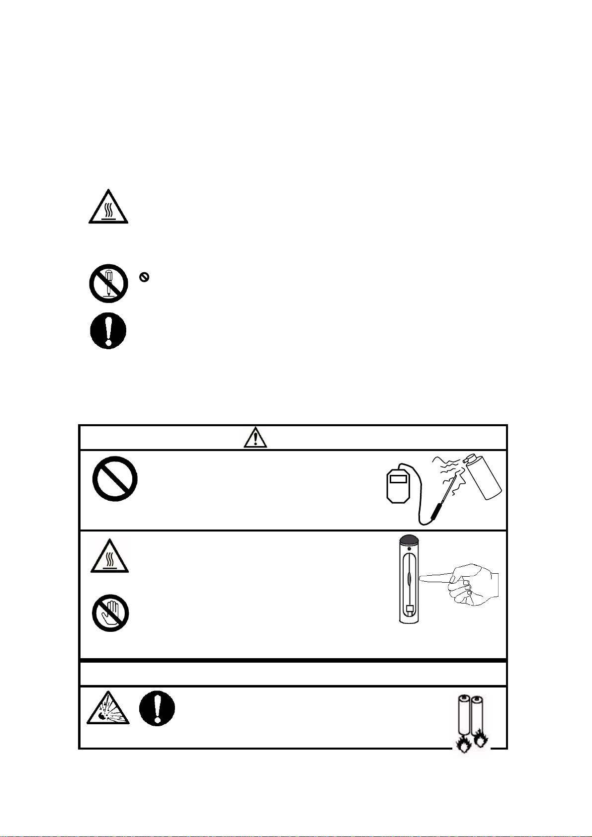
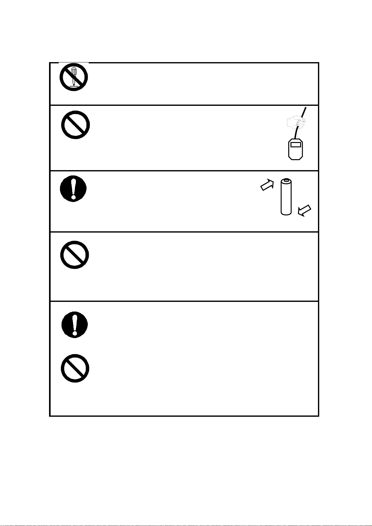
WARNING
Never bring the probe close to a
flammable gas atmosphere.
>>> The heated sensor may cause fire or explosion.
Never touch the sensor.
>>> The sensor is heated during operation.
Touching the heated sensor may cause burns,
and may also damage the sensor itself.
WARNING
Do not disassemble or heat batteries or do not
throw the battery in the fire.
>>> The battery may explode.
Do not use near
flammable gas.
High
Temperature
Never touch
Explosive
Handle
Properly
the product that may void the product warranty.
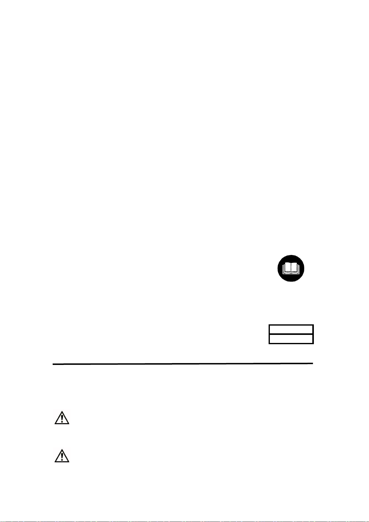
[Description of Symbols]
△ Indicates the condition (including danger) that requires caution. The subject of
each caution is illustrated inside the triangle (e.g., the symbol shown on the left is
high temperature caution).
Indicates prohibition. Do not take the prohibited action shown inside or near this
symbol (e.g., thy symbol shown on the left prohibits disassembly).
● Indicates a mandatory action. A specific action is given near the symbol.s
Page 4
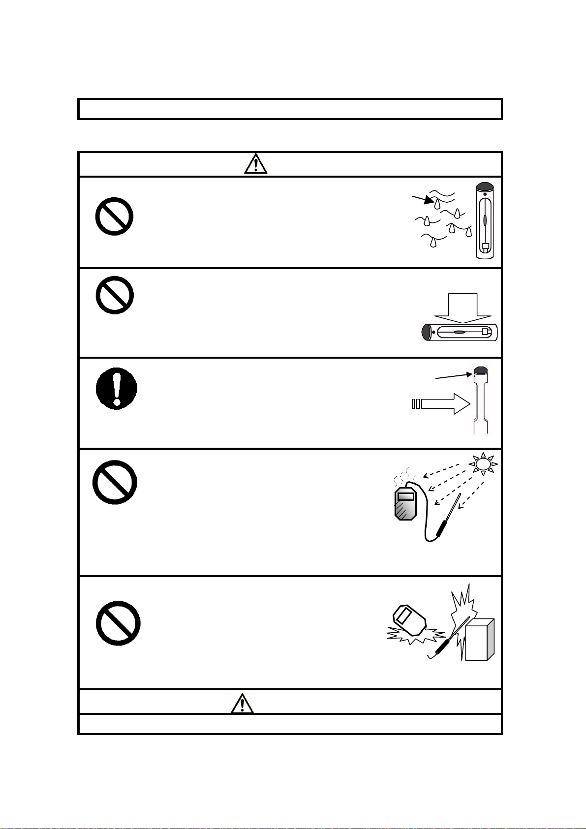
CAUTION
Do not use the instrument in a water vapor
atmosphere.
>>> Failure to observe above may cause electrical
shock, fire, or damage to the sensor.
Do not apply unnecessary excess force to the sensor.
>>> If the sensor is deformed, the accuracy of the sensor
cannot be maintained. Moreover, the sensor may be
broken.
When measuring, make sure to direct the wind
direction mark on the probe facing the wind.
>>> Otherwise the accurate measurement cannot be
performed.
Do not use or leave the instrument in a high
temperature / humidity environment, or in a
dusty environment.
Do not leave the instrument under direct
sunlight for a prolonged period.
>>> The instrument may not function properly out
of the specified operating conditions
Do not apply strong shock to the main unit or
probe.
>>> Failure to observe the above may cause
damage or malfunction to the instrument.
CAUTION
Wind
direction mark
Water
drops
Prohibition
Prohibition
Force
Set up properly
Prohibited
Installation
Prohibition
Page 5
Never disassemble, modify or repair the product.
>>> Failure to observe the above may cause short circuit and/or other failure that
will affect the performance.
Never hang the unit down by holding the probe cable.
>>> Failure to observe the above may damage the
instrument.
Install the batteries observing the correct polarity.
>>> Installing the batteries with wrong polarity may cause
battery leakage or damage the instrument.
Do not wipe the instrument with a volatile solvent.
>>> The body may deform or deteriorate. Use soft dry cloth to remove stains. If
stains persist, soak the cloth in a neutral detergent and wipe the instrument
with the soft cloth. Never use volatile solvents such as thinner or benzine.
Check tip of probe periodically and make sure it is clean. Unclean
sensor may affect the accuracy.
>>> To get rid of dust blow it away using blower brush for a camera or
something similar. Or quickly rinse the probe with water and dry it well.
* When cleaning the air velocity sensor, make sure to turn off the power of the
instrument.
* Never use heat to dry the probe, or the sensor will be damaged and it cannot
be repaired.
Clean up
Never dry by
Insert correctly
Do not modify /
disassemble.
Prohibited
Prohibition
Page 6

Table of Contents
1. Part Names and Functions (Main body) ............................................... 1
2. Part Names and Functions (Probe) ...................................................... 2
3. Getting Started .................................................................................... 3
4. Measuring ........................................................................................... 4
5. Battery Level Indicator ........................................................................ 5
6. Changing unit ...................................................................................... 5
7. Specifications ...................................................................................... 6
8. Troubleshooting .................................................................................. 7
9. Correction of Air Velocity Value ........................................................ 8
10. Warranty and after service ................................................................. 9
11. Contact Information ...................................................................... 11
Page 7

1
Approx. 120 mm
Power/Function Switch
Probe Connector
* Do not disconnect the
probe connector except
when changing the probe.
Battery Compartment
Approx.34mm
Approx.60 mm
(1) ON/OFF
(Press more than
one second)
(3) Pause
(2) FAST/SLOW
/Air temp.(Only A004)
Display
1. Part Names and Functions (Main body)
<Side> <Front>
<Back>
<Enlarged View of Power / function Switch>
* Power / Function switch is three-way switch;
slide up & down and push.
(1) Press the switch to turn ON/OFF the power.
Press the button for more than one second,
and release it when the LCD is lit.
(2) Slide the switch downward to change the
measurement mode as follows;
FAST→SLOW→Air temp. (Only A004)→
(3) Slide the switch upward to pause the screen.
Press any switch to release this function.
Page 8

2. Part Names and Functions (Probe)
Approx. φ6.1
Approx.28
mm
Directional point
Approx. 205
* Make sure that this
point is facing wind.
Sensor
Approx.10
0
* Air velocity & air temperature
(temperature compensation) sensor
is built-in.
* While measuring, make sure that
the whole window part faces wind.
Grip
Approx.φ10.6
Approx.φ3.3
Cable length: Approx. 1500
* When changing the probe, press
the buttons on both sides of the
connector to disconnect the probe.
Unit: mm
Page 9

3
+
-
-
-
-
+
+
+
(1) Slide the lid of the
battery compartment
toward the bottom of
the instrument until
it stops.
(2) Lift the cover away
from the instrument.
(3) Insert batteries
ensuring the battery
polarity is correct.
(4) Put the cover back on
by reversing the
procedure (1) and (2).
* When you put the cover back, do
not insert the tabs of the cover but
slide it back up.
(Do not force put the cover back,
or you may break the tabs.)
1
2
3
4
3. Getting Started
- How to Install Batteries-
<Back (Battery Compartment)>
Use four (4) AA batteries.
When you replace the batteries, make sure that the power is turned off.
When you use Ni-Cd batteries, charge it using the dedicated charger.
Page 10

4. Measuring
(1) ON/OFF
(Press more than
one second)
(3) Pause
(2) FAST/SLOW
/Air temp.(Only A004)
Turn the power ON
All items are displayed.
* They are displayed for one second.
Air velocity measurement
mode (FAST)
* When the power is turned ON,
the air velocity measurement
mode (FAST) will be selected
automatically.
Press the switch for
more than one second
* Only A004
Slide the switch
downward once.
Air velocity measurement
mode (SLOW)
Slide the switch
upward once.
Pause
Slide the switch
downward twice.
Air temperature
measurement mode
<How to Change Response (Only for air velocity measurement mode)>
Every time you slide the switch downward, the response time will be switched over; 1 sec
(FAST) or 5 sec (SLOW). (If you are using MODEL A004, Air Temperature Measurement
mode is added between 1 sec and 5sec.)
Once you turn the power OFF, it will return to the initial setting of one second (FAST).
If the fluctuation in a measurement value is relatively big, select “SLOW” to make the reading
easier.
<How to Measure Air Temperature (MODEL A004)>
After you turn the power ON, slide the switch downward twice to select the Air Temperature
mode.
Do not perform a measurement right after you switch to the Air Temperature mode. Especially
where there is hardly wind (air velocity is 0.1m/s or lower), make sure to wait for at least 30
seconds before starting a measurement.
Page 11

5
* We do not use SW 2.
1
2
OFF
SW No.
Unit
1
m/s ˚C
OFF (before shipping)
FPM ˚F
ON
Display blinks on and off.
(More than 4.6V)
(4.6 ~ 4.3V)
(4.3 ~ 4.0V)
(Less than 4.6V)
Time to replace
the batteries
Medium
Enough
5. Battery Level Indicator
Remaining battery level is indicated as follows.
The operation is guaranteed when the battery voltage is more than 4V.
When the battery voltage level becomes less than 4V, the display starts blinking. After a while,
the power goes off automatically.
When using Ni-Cd battery, charge the battery earlier (before the remaining battery level
indicator indicates 4.3 ~4.0V).
6. Changing unit
You can change the unit used in the
value by DIP switch.
The DIP switch is located inside the
battery compartment.
Page 12

7. Specifications
Model
A003
A004
Measurement Object
Clean air of normal pressure/normal humidity
Range
Air velocity
0.1 ~ 20.0m/s (20 ~ 3940 FPM)
Air temp.
-
0 ~ 50.0 ˚C (32 ~ 122 ˚F)
Accuracy
Air velocity
±3% of reading or 0.015m/sec (3 fpm) whichever is greater
Air temp. - ± 1 ˚C (± 2 ˚F)
Temp.
compensation
accuracy
Air velocity
Between 10 ~ 40 ˚C (50 ~ 104 ˚F)
Display
resolution
Air velocity
0 ~ 9.99 m/s
: 0.01 m/s (Minimum)
10.0 ~ 20.0 m/s
: 0.1 m/s
0 ~ 1958 FPM
: 2 FPM (Minimum)
1960 ~ 3940 FPM
: 20 FPM
Air temp. - 0.1 ˚C (0.2 ˚F)
Response
Air velocity
Less than one second
(Air velocity 1 m/s (196 FPM): 90 % Response)
Air temp.
-
Less than 30 seconds
(Air velocity 1m/s (196 FPM) 90 % )
Function
(1) Battery level indicator (4 levels)
(2) FAST / SLOW (moving average for 1 or 5 sec.)
(3) Changing unit by DIP switch (m/s, ˚C → FPM ˚F)
(4) Pausing display
Dimensions
Probe: Approx.φ6.1 (φ10.6) × 200 mm (Cable: φ3.3 × 1.5 m)
Main body: Approx. 60 (W) × 120 (L) × 30 (D) mm
Power source
Four (4) AA batteries: Manganese battery, Alkaline battery, Ni-Cd
battery (Use the dedicated charger for Ni-Cd battery.)
Battery life
Approx. 4 hours (When performing a continuous measurement at
the air velocity of 1 m/s (196FPM) operated by manganese
batteries)
Operating temp. limit for probe
0 ~ 50 ˚C (32 ~ 122 ˚F)
Operating temp. limit for main unit
5 ~ 40 ˚C (41 ~ 104 ˚F)
Temperature limit for storage
-10 ~ 50 ˚C (14 ~ 122 ˚F)
Weight
Approx. 180 g (including batteries)
Standard accessories
AA size battery: 4
Operation Manual: 1
Options
Telescopic Extension rod, Spare probe, Carrying Case
Degree of protection
IP40
Page 13

7
Symptom
Possible cause
Corrective action
The power cannot be
turned ON.
(LCD does not display
anything.)
The batteries may be running low.
Replace the batteries.
Battery polarity may not be
correct.
Insert the batteries properly.
Contact points may be dirty.
Clean the contact points of
battery.
“- - - -” (OVER) is
displayed.
The instrument may not be being
used within the measuring range.
Use the instrument within the
measuring range.
Air velocity sensor may be
damaged.
Contact your distributor or to
your KANOMAX service center.
“E01” is displayed or
“0.00” display does
not change.
Air velocity sensor may be
damaged.
Contact your distributor or to
your KANOMAX service center.
Probe cable may be damaged.
Contact your distributor or to
your KANOMAX service center.
“E02” is displayed
Air temperature sensor may be
damaged.
Contact your distributor or to
your KANOMAX service center.
Display is frozen.
The unit may be temporally
paused.
Release pause.
The batteries may be running low.
Replace the batteries.
Display blinks on and
off.
The batteries may be running low.
Replace the batteries.
Battery polarity may not be
correct.
Insert the batteries properly.
Contact points may be dirty.
Clean the contact points of
battery.
Indicated units are
different.
Unit setting may have been
changed.
Change the unit by using the DIP
switch inside battery
compartment.
Symptom
Possible cause
Corrective action
“E01” is displayed or
“0.00” display does
not change.
Connector may not be connected
correctly.
Turn the power off and connect
the connector again.
The probe may have been
replaced while the power was on.
Turn the power on again.
Symptom
Possible cause
Corrective action
The power cannot be
ON.
Batteries may have been replaced
while the power was on.
Remove all the batteries and
insert them again.
8. Troubleshooting
Please check the followings once again before you before you contact us for service.
(1) At normal condition
(2) When you replace probe
(3) When you replace battery
Page 14

9. Correction of Air Velocity Value
c
m
m
U
P
U
1013
Air temperature, humidity and pressure may influence the accuracy of air velocity.
<Influence by air temperature>
This is a Thermal (Hot-Wire) Anemometer which measures air velocity based on the heat diffusion
quantity. Therefore, if you do not correct the value based on the surrounding environment, the
instrument reading will vary depending on the air temperature. Although the actual velocities are
the same, the reading may not be the same depending on the air temperature because the air
temperature changes the heat diffusion quantity. In order to prevent this, temperature compensation
circuit is installed to measure air temperature to compensate the air velocity value to make sure that
the air temperature does not influence the air velocity value in the range of 10 ~ 40 ˚C.
<Influence by humidity>
Since air velocity sensor is normally heated to 40 ~ 50 ˚C above the ambient temperature, it is not
influenced by relative humidity.
<Influence by atmospheric pressure>
Change of pressure influences heat radiation. Calibration of atmospheric pressure is as follows.
Um: True air velocity [m/s]
Uc: Indicated air velocity [m/s]
Pm: Pressure at measuring [hPa]
Page 15

9
10. Warranty and after service
Kanomax Limited Warranty
The limited warranty set below is given by KANOMAX with respect to the KANOMAX brand Anemomaster,
Model A003 / A004, its attachment parts including Probe and other accessories (hereafter referred to as
“PRODUCT”) that you have purchased. PRODUCT you have purchased shall be the only one that the limited
warranty stated herein applies to.
Your PRODUCT, when delivered to you in new condition in its original container, is warranted against defects in
materials or workmanship as follows: for a period of one (1) year from the date of original purchase, defective parts
or a defective PRODUCT returned to your sales representative, as applicable, and proven to be defective upon
inspection, will be exchanged for a new or comparable rebuilt parts, or a refurbished PRODUCT as determined by
your sales representative. Warranty for such replacements shall not extend the original warranty period of the
defective PRODUCT.
This limited warranty covers all defects encountered in normal use of the PRODUCT, and does not apply to the
following cases:
(1) Use of parts or supplies other than the PRODUCT sold by your sales representative, which cause damage to
the PRODUCT or cause abnormally frequent service calls or service problems.
(2) If any PRODUCT has its serial number or date altered or removed.
(3) Loss of damage to the PRODUCT due to abuse, mishandling, improper packaging by the owner, alteration,
accident, electrical current fluctuations, failure to follow operating, maintenance or environmental instructions
prescribed in the PRODUCT's instruction manual provided by KANOMAX, or service performed by other
than KANOMAX.
NO IMPLIED WARRANTY, INCLUDING ANY IMPLIED WARRANTY OF MERCHANTABILITY OR
FITNESS FOR A PARTICULAR PURPOSE, APPLIES TO THE PRODUCT AFTER THE APPLICABLE
PERIOD OF THE EXPRESS LIMITED WARRANTY STATED ABOVE, AND NO OTHER EXPRESS
WARRANTY OR GUARANTY, EXCEPT AS MENTIONED ABOVE, GIVEN BY ANY PERSON OR
ENTITY WITH RESPECT TO THE PRODUCT SHALL BIND KANOMAX. KANOMAX SHALL NOT BE
LIABLE FOR LOSS OF STORAGE CHARGES, LOSS OR CORRUPTION OF DATA, OR ANY OTHER
SPECIAL, INCIDENTAL OR CONSEQUENTIAL DAMAGES CAUSED BY THE USE OR MISUSE OF,
OR INABILITY TO USE, THE PRODUCT, REGARDLESS OF THE LEGAL THEORY ON WHICH THE
CLAIM IS BASED, AND EVEN IF KANOMAX HAS BEEN ADVISED OF THE POSSIBILITY OF SUCH
DAMAGES. IN NO EVENT SHALL RECOVERY OF ANY KIND AGAINST KANOMAX BE GREATER
IN AMOUNT THAN THE PURCHASE PRICE OF THE PRODUCT SOLD BY KANOMAX AND
CAUSING THE ALLEGED DAMAGE. WITHOUT LIMITING THE FOREGOING, THE OWNER
ASSUMES ALL RISK AND LIABILITY FOR LOSS, DAMAGE OF, OR INJURY TO THE OWNER AND
THE OWNER'S PROPERTY AND TO OTHERS AND THEIR PROPERTY ARISING OUT OF USE OR
MISUSE OF, OR INABILITY TO USE, THE PRODUCT NOT CAUSED DIRECTLY BY THE
NEGLIGENCE OF KANOMAX. THIS LIMITED WARRANTY SHALL NOT EXTEND TO ANYONE
OTHER THAN THE ORIGINAL PURCHASER OF THE PRODUCT, OR THE PERSON FOR WHOM IT
WAS PURCHASED AS A GIFT, AND STATES THE PURCHASER'S EXCLUSIVE REMEDY.
Page 16

After Service
Whenever the PRODUCT is malfunctioning, please check with “Troubleshooting” to find
possible cause first.
Repair parts are retained for a minimum period of five (5) years after production cessation of
the PRODUCT. This storage period of repair parts is considered as the period during which
KANOMAX can provide repair service.
For more information, please contact your sales representative. When you make a call, please
have the following information of your PRODUCT at hand:
(1) PRODUCT name;
(2) Model number;
(3) Serial number;
(4) Probe number;
(5) Description of Symptom, and;
(6) Date of purchase
Page 17

11
11. Contact Information
U.S.A. & Europe
KANOMAX USA, INC.
PO Box 372, 219 US Hwy 206, Andover, NJ 07821 U.S.A.
TEL: (800)-247-8887 / (973)-786-6386 FAX: (973)-786-7586
URL: http://www.kanomax-usa.com/
E-Mail: info@kanomax-usa.com
Japan & Asia
KANOMAX JAPAN, INC.
2-1 Shimizu Suita City, Osaka 565-0805, Japan
TEL: 81-6-6877-0183 FAX: 81-6-6877-5570
URL: http://www.kanomax.co.jp/
E-Mail: sales@kanomax.co.jp
China
Shenyang Kano Scientific Instrument Co., Ltd
No. 12, 4 Jia Wencui Road Heping District
Shenyang City PRC
TEL: 86-24-23845309 FAX: 86-24-23898417
URL: http://www.kanomax.com.cn/
E-mail: sales@kanomax.com.cn
 Loading...