


INSTRUCTION MANUAL
KU SERIES FULL-SIZE UNDERCOUNTER REFRIGERATORS
KU044SC, KU072SC & KU100SC
SALES KAIRAK. 1158 N. Gilbert St., Anaheim, CA 92801, Phone: (714) 870-8661, Web: www.kairak.com MNFG KAIRAK. 4401 Blue Mound Road, FT. Worth, TX 76106
© KAIRAK, a division of ITW Food Equipment Group LLC. All Rights Reserved.
Undercounter Refrigerators and Freezers
PAGE 1

TABLE OF CONTENTS
1. THE SERIAL TAG |
page |
3 |
2. RECEIPT INSPECTION |
page |
4 |
3. INSTALLATION |
|
|
a-Locating the Equipment |
page |
4 |
b-Packaging |
page |
4 |
c-Adjusting the Casters |
page |
5 |
D-Cord and Plug |
page |
5 |
E-Power Supply |
page |
5 |
4. Operation |
|
|
a-Refridgerators |
page |
6 |
b-Freezers |
page |
6 |
5. Care and Maintenance |
|
|
a-Cleaning the Condenser/Filter |
page |
7 |
b-Replacing the Gaskets |
page |
8 |
c-Cleaning the Cabinet Surface |
page |
8 |
6. DOOR(S) & REFRIGERATOR DRAWER(S) |
|
|
a-Door Re-hinging |
page |
9 |
B-Removing the Door and Installing Ref Drawers |
page |
9 |
7. Microprocessor Control |
Page 10 |
|
a-Control Features |
Page 10 |
|
B-Alarm Explanations |
Page 11 |
|
C-Control Panel Diagram |
Page 13 |
|
D- Notes to User |
page 13 |
|
e-Enter The Service Access |
Page 14 |
|
f-Service Parameters |
page 15 |
|
g-Adjusting Thermostat Set Point High |
page 16 |
|
h-Adjusting Thermostat Set Point Low |
page 16 |
|
i-Changing The Temperature Scale |
page 17 |
|
j-Setting The 24-Hour Clock |
page 18 |
|
k-Setting The Date |
page 19 |
|
l-Setting Daylight Savings Time |
page 19 |
|
m-Starting A Manual Defrost |
page 20 |
|
n-Setting Defrost Lockouts |
page 22 |
|
o-Adjusting The Drawer Perimeter Heaters |
page 23 |
|
p-Adjusting The Room Temperature Offset |
page 23 |
|
q-Setting The Audible Alarm Style |
page 24 |
|
r-Viewing Sensor Temperatures |
page 24 |
|
8. Wiring Diagram |
page 25 |
|
9. TROUBLESHOOTING GUIDE |
page 26 |
|
10. WARRANTIES |
page 27 |
|
11. notes |
page 28 |
|

1. The serial tag
The serial tag is a permanently affixed label on which is recorded vital electrical and refrigeration data about your Kairak product, as well as the model and serial number. This tag is located inside the lower storage cabinet on the right hand wall on all standard KRP models. Prior to installation, test the electrical service to assure that it agrees with the specifications of the equipment marked on the serial tag.
READING THE SERIAL TAG
•Serial = The permanent ID# of your Kairak unit
•Model = The model # of your Kairak unit
•Volts = Voltage
•Hz = Cycle
•PH = Phase
•Total Current = Maximum amp draw
•Minimum Circuit = Minimum circuit ampacity
•Lights = Light wattage
•Heaters = Heater amperage (Hot Food units only)
•Refrigerant = Refrigerant type used
•Design Pressure = High & low side operating pressures and refrigerant charge
•Agency Labels = Designates agency listings
SERIAL |
|
MODEL |
|
|
VOLTS |
|
Hz |
PH |
|
TOTAL CURRENT |
|
AMPS |
|
|
MINIMUM CIRCUIT |
AMPS |
|
|
|
MAXIMUM OVERCURRENT PROTECTION |
AMPS |
|||
LIGHTS |
|
WATTS |
|
|
HEATERS |
AMPS |
|
|
|
REFRIGERANT |
|
TYPE |
OZ |
|
DESIGN PRESSURE |
HIGH |
LOW |
|
|
REFRIGERANT |
|
TYPE |
OZ |
|
DESIGN PRESSURE |
HIGH |
LOW |
|
|
FIG. 1
Undercounter Refrigerators and Freezers
PAGE 3

2. RECEIPT INSPECTION
All Kairak products are factory tested for performance and are free from defects when shipped. The utmost care has been taken in crating this product to protect against damage in transit.
You should carefully inspect your Kairak unit for damage during delivery. If damage is detected, you should save all the crating materials and make note on the carrier’s Bill Of Lading describing the damage. A freight claim should be filed immediately. If damage is subsequently noted during or immediately after installation, contact the respective carrier and file a freight claim. There is a fifteen (15) day limit to file freight damage with the carrier. Under no condition may a damaged unit be returned to Kairak without first obtaining written permission (return authorization). You may contact Kairak customer care at (714) 870-8661 to request a return.
3. installation
3A - Location:
Select a proper location for your unit, away from extreme heat or cold. Allow enough clearance between the unit and the side wall in order to make use of the door stay open feature at 1200 (self-closing feature operates up to 900). The door(s) must be able to open a minimum of 900 in order to make use of the maximum clear door width.
3B - packaging:
Your Kairak unit is shipped from the factory bolted to a sturdy wooden pallet in stretch wrapped material.
Most exterior stainless steel surfaces have a protective vinyl covering to prevent scratching during manufacturing, shipping and installation. After the unit is installed in place of application peel, remove and discard the covering from all surfaces.
To remove the wooden pallet, first if at all possible, we suggest that the cabinet remain bolted to the pallet during all transportation to the point of final installation. The bolts can then be removed with a 1/2” socket wrench. Avoid laying the unit on its front, side or back for removal of the pallet.
NOTE: Kairak does not recommend laying the unit on its front, side or back. If you must, please allow the unit to remain in an upright position for 24 hours before plugging it in so that the compressor oils and refrigerant may settle.
Undercounter Refrigerators and Freezers
PAGE 4
3. installation (CONT.)
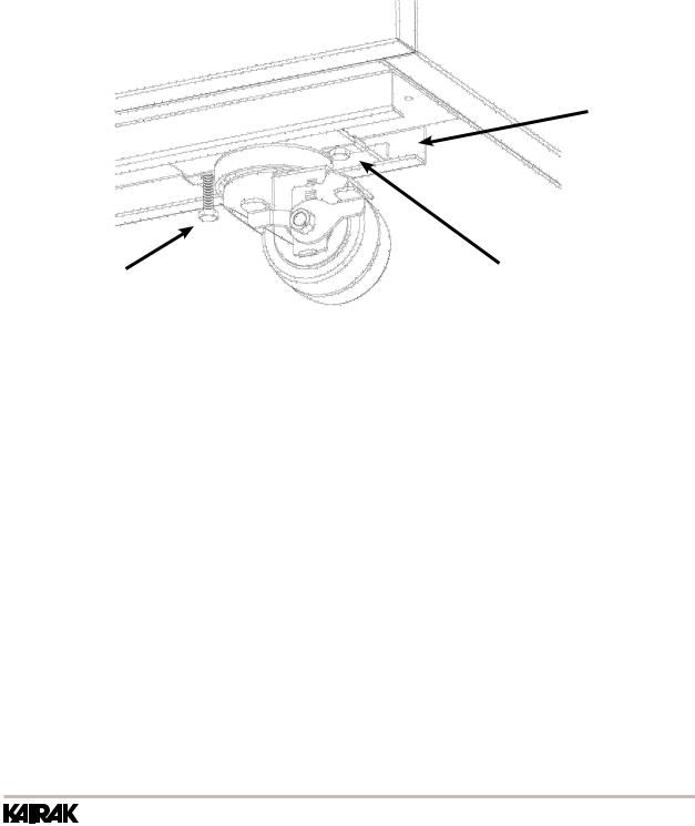
3C - INSTALLING/ADJUSTING LEGS OR CASTERS:
To install legs or casters, slide leg or caster into the caster channel from the side of the unit without the refrigeration system.
To adjust the legs or casters, loosen the two bolts and move leg or caster to desired location, spacing between leg or caster not to exceed 48 inches. Leg or caster on each end of the unit can not exceed 8 inches from the end of the cabinet (Figure 1).
NOTE: Kairak recommends to position legs or casters under the mullion when possible.
Caster Channel
bolt |
|
|
Caster |
|
|
||
|
|
Plate |
|
|
|
|
|
|
|
Caster |
|
Figure 1
3D - CORD & PLUG:
All self-contained models are shipped standard with a NEMA 5-15P plug and 9 foot cord. Select only a dedicated electrical outlet for power source.
NOTE: Do not under any circumstances, cut or remove the round grounding prong from the plug, or use an extension cord.
3E - POWER SUPPLY:
The supply voltage should be checked prior to connection to be certain that proper voltage for the cabinet wiring is available (refer to the serial tag to determine correct unit voltage, see page 1). Make connections in accordance with local electrical codes. Use qualified electricians.
Use of a separate, dedicated circuit is required. Size wiring to handle indicated load and provide necessary overcurrent protector in circuit (see amperage requirements on the unit’s serial tag).
Undercounter Refrigerators and Freezers
PAGE 5
4. Operation
4a - Refrigerators
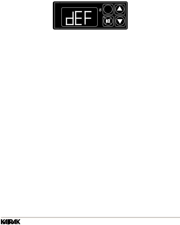
Both refrigerators and Freezers do not require manual defrosting. During normal operation, a refrigerator continuously circulates above freezing cabinet air through the coil. A compressor “OFF” cycle occurs every 2 1/2 Hours for 20 minutes to melt any frost which may accumulate on the coil during the compressor “ON” cycle. The control will read “dEF” and the green water drop will be illuminated (Figure 2). With standard holding refrigerators, high relative humidity is also maintained to prevent dehydration of stored product.
FREEZER

INTELA-TRAUL
°F |
°C |
SET |
Figure 2
4B - FREEZERS:
During normal operation, a freezer continuously circulates below freezing cabinet air through the coil. The coil requires a periodic defrosting for proper operation. This is accomplished by an automatic, time activated, temperature/time terminated, defrost program, utilizing hot gas from the refrigeration system. The controller is preset at the factory for six equally spaced defrost cycles within each 24-hour period.
At the start of a freezer defrost cycle, the compressor, condenser fan and evaporator fan shut off. The hot gas relay will be energized, this will energize the hot gas solenoid valve thru the normally open contacts and the condenser fan circuit will be de-energized thru the (normally closed contacts), and the compressor will restart. When the evaporator coil sensor reaches 400 F the coil is fully defrosted or if the maximum time of defrost duration (20 minutes) is reached (which ever comes first) then the defrost hot gas relay is de-energized. The condenser fan restarts and the hot gas solenoid valve closes, The compressor system returns to the cooling mode. Total refrigeration system operation is then resumed (green snowflake icon goes out) and the display will show def for an additional 10 minutes then return to reading the inside cabinet temperature. The evaporator fan(s) are delayed from starting at the termination of the defrost cycle and will automatically resume by time or temp delay (5 minutes or 300 F coil sensor temperature, whichever comes first ).
During freezer defrost operation, heat is confined to the coil enclosure to prevent any significant rise in temperature within the food zone. The fan delay control function upon termination of a defrost cycle is two-fold. First, to prevent blowing warm air into the food storage area. Second, to prevent any condensation on the defrost coil from being blown into the food storage area.
The microprocessor control is set from the factory to terminated defrost at 20 minutes in the event of sensor failure. This setting should never be tampered with, without first consulting Kairak’s Technical Service department.
Undercounter Refrigerators and Freezers
PAGE 6

5. cleaning the condenser/filter
The most important thing you can do to insure a long, reliable service life for your Kairak is to regularly clean the condenser coil and or filter if provided.
The microprocessor control will notify you through a “CLN-FIL” message when the condensing temperature of the refrigerator reaches 140 degrees F or greater. If the condensing temperature reaches 160 degrees F the compressor will automatically turn off . When the temperature drops below 140 degrees F the compressor will restart and when the temperature drops below 120 degrees F the alarm will reset.
WARNING: DISCONNECT ELECTRICAL POWER SUPPLY BEFORE CLEANING ANY PARTS OF THE UNIT.
To clean the condenser/filter, first disconnect electrical power to the cabinet and remove the front louver assembly. To do so, place hands under the louver panel and pull out and up to get louver panel off bracket of the unit (Figure 3).
Figure 3
Proceed to vacuum or brush any dirt, lint or dust from the finned condenser coil/filter, the compressor and other cooling system parts. If significant dirt is clogging the condenser fins or filter, use compressed air to blow this clear. To replace the louver assembly reverse the process.
Undercounter Refrigerators and Freezers
PAGE 7
5. cleaning the condenser/
filter (Cont.)
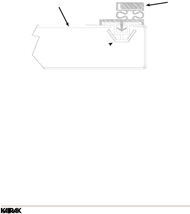
5B - REPLACING THE GASKETS:
To remove the gasket to be replaced, grasp it firmly by one corner and pull it out. Before attempting to install a new gasket, both the unit and the gasket itself must be at room temperature. Insert the four corners first by using a rubber mallet (or hammer with a block of wood). After the corners are properly inserted, work your way towards the center from both ends by gently hitting with a mallet until the gasket is completely seated in place (see figure below for proper gasket placement).
NOTE: The gasket may appear too large, but if it is installed as indicated above it will slip into place.
gasket inside drawer assembly panel
vertical gasket  retainer
Figure 4
5C - CLEANING THE CABINET SURFACES:
WARNING: DISCONNECT ELECTRICAL POWER SUPPLY BEFORE CLEANING ANY PARTS OF THE UNIT.
Exterior stainless steel should be cleaned with warm water, mild soap and a soft cloth. Apply with a dampened cloth and wipe in the direction of the metal grain.
Avoid the use of strong detergents and gritty, abrasive cleaners as they may tend to mar and scratch the surface. Do NOT use cleansers containing chlorine, such as bleach, this may promote corrosion of the stainless steel.
Care should also be taken to avoid splashing the unit with water, containing chlorinated cleansers, when mopping the floor around the unit.
For stubborn odor or spills, use baking soda and water (mixed to a 1 tbsp baking soda to 1 pint water ratio).
A stainless steel polish is recommended for shining of unit.
Undercounter Refrigerators and Freezers
PAGE 8
6. Door(s) and Refrigerator
Drawer(s)
Your Kairak full-size undercounter model door(s) are field re-hingeable. If re-hinging is required, please contact our in-house service department at 800-833-1106 for instruction.
6A - REMOVING THE DOOR AND INSTALLING REF DRAWERS:
Doors are supplied standard on all TU Series Full-Size Undercounter models. However, we have engineered our refrigerator models (only) with a drop-in feature that allows you to easily convert door(s) into two 6” deep drawers or three 4” deep drawers.
The door(s) on the refrigerator models (only) can easily be converted to drawers in the field. To begin the process, open the door to its maximum position. Support the nonhinged end of the door so minimum movement occurs. When the bolts from the lower hinge plate are removed, remove the lower hinge plate and then the door from the top hinge bracket plate and then the door from the top hinge bracket. The hinge plate pin and plastic bushing will remain in the top hinge plate.
NOTE: The lower hinge plate is under spring tension.
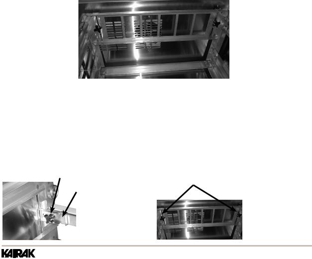
Once the door(s) have been removed, Insert drawer frame as shown below (Figure 5).
Figure 5
Once the drawer frame has been inserted, the drawer frame module can be installed by tighting the black front and back clamping knobs (2 of each) located on the cross rail locks and liner locks. Slide the front cross rail locks towards the center of the drawer frame module and allow the liner locks to drop down from the top of the liner. Insert the door frame module push towards the back of the unit. The entire frame assembly is now installed and ready for use.
NOTE: Repeat process for multiple drawer(s) inserts.
Front Clamping Knobs
Back Clamping Knobs
Front Cross
Rail Locks
Undercounter Refrigerators and Freezers
PAGE 9
 Loading...