


REMOTE RACK SYSTEM
OWNERS MANUAL
INSTALLATION – OPERATIONS - MAINTENANCE
4401 Blue Mound Rd. Fort Worth, TX 76106
Phone: (714) 870-8661 Toll-Free: (800) 833-1106 Fax: (714) 870-6473 www.kairak.com
© KAIRAK, a Division of ITW Food Equipment Group, LLC. All Rights Reserved
ANSI/UL Std. 1995-CAN/CSA C22.2 No. 236 M05 (Intertek #4004142)

1. |
INTRODUCTION..................................................................................................................................................................... |
3 |
2. |
COMPLETION REPORT – SERVICE RECORD – WARRANTY ...................................................................................................... |
3 |
3. |
FEATURES ............................................................................................................................................................................. |
4 |
3.1 |
CONDENSING UNIT................................................................................................................................................................... |
4 |
3.2 |
REFRIGERANT ........................................................................................................................................................................... |
5 |
3.3 |
CONTROL PANEL....................................................................................................................................................................... |
5 |
3.4 |
ELECTRICAL DEFROST ............................................................................................................................................................... |
5 |
3.5 |
ELECTRICAL REQUIREMENTS .................................................................................................................................................... |
6 |
3.6 |
STANDARD COMPONENTS ....................................................................................................................................................... |
6 |
3.7 |
ACCESSORIES – STANDARD....................................................................................................................................................... |
6 |
3.8 |
HEAD PRESSURE CONTROL VALVE ............................................................................................................................................ |
6 |
3.9 |
ETL APPROVAL .......................................................................................................................................................................... |
6 |
3.10 |
WALK IN EVAPORATOR COILS................................................................................................................................................... |
7 |
4. |
DIMENSIONAL DATA............................................................................................................................................................. |
8 |
5. |
INSTALLATION ...................................................................................................................................................................... |
9 |
5.1 |
RECEIPT AND INSPECTION OF EQUIPMENT .............................................................................................................................. |
9 |
5.2 |
LIFTING INSTRUCTIONS ............................................................................................................................................................ |
9 |
5.3 |
LOCATION AND VENTILATION ................................................................................................................................................ |
10 |
5.4 |
ROOF PLATFORM REQUIREMENTS ......................................................................................................................................... |
11 |
5.5 |
PITCH POCKET......................................................................................................................................................................... |
11 |
5.6 |
ELECTRICAL ............................................................................................................................................................................. |
11 |
5.7 |
PLATFORM DIMENSIONS........................................................................................................................................................ |
13 |
5.8 |
WIRING DIAGRAM – WALK IN COOLER ................................................................................................................................... |
14 |
5.9 |
WIRING DIAGRAM – WALK IN FREEZER .................................................................................................................................. |
15 |
6. |
REFRIGERATION.................................................................................................................................................................. |
16 |
6.1 |
PIPING..................................................................................................................................................................................... |
16 |
6.2 |
STANDARD PIPING PROCEDURES ........................................................................................................................................... |
17 |
6.3 |
LEAK TESTING ......................................................................................................................................................................... |
17 |
6.4 |
SYSTEM EVACUATION............................................................................................................................................................. |
18 |
6.5 |
SYSTEM CHARGING (LESS FLOODED HEAD PRESSURE CONTROL)........................................................................................... |
18 |
6.6 |
SYSTEM CHARGING (WITH FLOODED HEAD PRESSURE CONTROL)......................................................................................... |
18 |
6.7 |
THERMAL EXPANSION VALVE ................................................................................................................................................. |
20 |
6.8 |
HOT GAS BYPASS..................................................................................................................................................................... |
21 |
6.9 |
FAN CYCLE CONTROL .............................................................................................................................................................. |
21 |
7. |
START-UP PROCEDURE........................................................................................................................................................ |
21 |
7.1 |
CONDENSING UNITS ............................................................................................................................................................... |
22 |
7.2 |
EVAPORATOR COIL – BEFORE START UP ................................................................................................................................. |
22 |
7.3 |
EVAPORATOR COIL – AFTER START UP.................................................................................................................................... |
23 |
7.4 |
OPERATIONAL CHECK-OUT..................................................................................................................................................... |
23 |
7.5 |
TIMER DIAL ............................................................................................................................................................................. |
25 |
7.6 |
SHUT DOWN ........................................................................................................................................................................... |
26 |
7.7 |
SYSTEM RESTART AFTER SHUT DOWN.................................................................................................................................... |
26 |
8. |
MAINTENANCE ................................................................................................................................................................... |
27 |
8.1 |
AIR-COOLED CONDENSER....................................................................................................................................................... |
27 |
KAIRAK REMOTE RACK SYSTEM |
PAGE 1 |
REV: 2-2014

8.2 |
ELECTRICAL AND PIPING CONNECTIONS ................................................................................................................................ |
27 |
8.3 |
CRANKCASE LUBRICATION...................................................................................................................................................... |
27 |
8.4 |
MAINTENANCE CHECKLIST (AT THE RACK) ................................................................................................................................. |
28 |
8.5 |
EVAPORATOR COIL ................................................................................................................................................................. |
28 |
8.6 |
HEATER REPLACEMENT IN LOW TEMP EVAPORATOR COIL .................................................................................................... |
29 |
9. |
TROUBLESHOOTING............................................................................................................................................................ |
30 |
10. |
TABLES AND CHARTS .......................................................................................................................................................... |
39 |
10.1 |
TEMPERATURE PRESSURE CHART........................................................................................................................................... |
39 |
10.2 |
LINE SIZING FOR REFRIGERATION SYSTEMS............................................................................................................................ |
40 |
Table 1: Pressure loss ...................................................................................................................................................................... |
40 |
|
Table 2: Equivalent Feet of Pipe Due to Valve and Fitting Friction.................................................................................................. |
40 |
|
Table 3: Weight Of Refrigerant ....................................................................................................................................................... |
41 |
|
Table 4: Recommended Remote Condenser Line Sizes.................................................................................................................... |
42 |
|
Chart 5: Recommended Line Sizes For R-404A ................................................................................................................................ |
43 |
|
Chart 6: Recommended Line Sizes For R-404A (Cont’d) .................................................................................................................. |
44 |
|
11. |
WIRING DIAGRAMS ............................................................................................................................................................ |
45 |
11.1 |
SINGLE EVAPORATOR W/WO DEFROST TIMER....................................................................................................................... |
45 |
11.2 |
SINGLE EVAPORATOR W/DEFROST TIMER ONLY .................................................................................................................... |
46 |
11.3 |
MULTIPLE EVAPORATORS W/DEFROST TIMERS ONLY............................................................................................................ |
47 |
11.4 |
SINGLE EVAPORATOR SINGLE PHASE DEFROST/EVAPORATOR FAN ....................................................................................... |
48 |
11.5 |
SINGLE EVAPORATOR DEFROST AND EVAPORATOR FAN CONTACTORS ................................................................................ |
49 |
11.6 |
MULTIPLE EVAPORATOR W/FAN CONTACTORS/NO HEATER LIMIT DEFROST........................................................................ |
50 |
11.7 |
MULTIPLE EVAPORATOR WITH HEATER LIMIT DEFROST AND EVAPORATOR ......................................................................... |
51 |
11.8 |
MULTIPLE EVAPORATOR DEFROST AND EVAPORATOR FAN CONTACTORS W/UNIT COOLER HOLDOUT RELAY .................... |
52 |
11.9 |
DEFROST CONTACTOR W/EVAPORATOR HOLDOUT RELAY W/O HEATER LIMIT .................................................................... |
53 |
11.10 DEFROST CONTACTOR W/EVAPORATOR HOLDOUT RELAY W/HEATER LIMIT........................................................................ |
54 |
|
11.11 MULTIPLE EVAPORATORS W/DEFROST SWITCHES IN SERIES, W/O HOLDOUT RELAYS/HEATER LIMITS ................................ |
55 |
|
12. |
PARTS LIST .......................................................................................................................................................................... |
56 |
13. |
WARRANTIES ...................................................................................................................................................................... |
63 |
14. |
REMOTE REFRIGERATION START-UP AND INSTALLATION COMPLETION REPORT AND RECORD.......................................... |
65 |
14.1 |
REMOTE RACK CONDENSING UNIT......................................................................................................................................... |
66 |
14.2 |
WALK-INS EVAPORATOR COIL.............................................................................................................................................. |
71 |
14.3 |
FIXTURES PREP TABLES COLD RAILS UNDER-COUNTER EQUIPMENT STANDS ALL OTHER ITEMS .............................. |
75 |
14.4 |
INSTALLTION/PIPING .............................................................................................................................................................. |
77 |
PAGE 2 |
KAIRAK REMOTE RACK SYSTEM |
|
REV: 2-2014 |

REMOTE RACK SYSTEM
1. INTRODUCTION
Kairak is committed to producing environmentally friendly and sustainable product offerings without sacrificing quality or reliability. Kairak Remote Rack system assures customers maximum energy savings and a substantially smaller environmental footprint. Kairak systems have been successfully integrated into LEED certified buildings.
The Kairak air cooled Remote Rack cooling system utilizes safe HFC’s and offers excellent operating efficiency by using multi-circuited condensers for up to 20 compressors and ice makers. This high operating efficiency is made through effective use of the condenser coil surface area. The large condenser coils provide the unit with summer design temperature differences (TD’s) lower than traditional designs allow. Lower design TD’s produce lower condensing temperatures which produce lower compression ratios and higher compressor capacities, thereby reducing operating cost. Kairak Remote Rack systems are easier to install, easier to service and much less expensive to operate. Complete factory assembly eliminates on-sight construction costs of built-up systems by refrigeration technicians and electricians in the field. The Kairak Remote Rack system is designed primarily for institutional food service operations including: hospitals, universities, schools, hotels, restaurants, coffee shops and convenience stores.
Kairak Remote Rack systems pull fresh air over the compressor bodies to reduce their operating temperature. Compressor ventilation has become increasingly important to extend its life span. R-404A refrigerant is used for all applications.
2. COMPLETION REPORT – SERVICE RECORD – WARRANTY
The Kairak completion report and record is located at the back of this manual. This must be filled out and a copy sent to Kairak for their review to begin warranty coverage of your rack system.
KAIRAK REMOTE RACK SYSTEM |
PAGE 3 |
REV: 2-2014
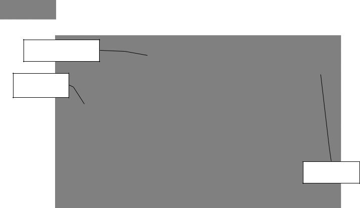
REMOTE
REFRIGERATION RACK
REFRIGERANT
LINES IN WALL
WALK-IN
EVAPORATOR
Figure 1
3. FEATURES
3.1 CONDENSING UNIT
Kairak Remote Rack systems will typically provide many years of trouble-free operation with minimal maintenance. The length of service from a condensing unit is greatly affected by the care taken during the original installation.
Cleanliness is absolutely mandatory when installing a condensing unit. Utmost care has been taken at the factory to insure that the unit is free of all contamination. The factory-applied seals must not be removed until the unit is ready for installation. All tubing, valves, and fittings must be carefully inspected to insure cleanliness.
The required electrical supply must be provided to the condensing unit control panel. The voltage at the motor-compressor terminals should be checked during start-up and unit operation under full load to insure a tolerance of +/- 10% of the system nameplate rating.
The lubrication recommendations for the motor-compressor and fan motors (where applicable) must be carefully adhered to.
PAGE 4 |
KAIRAK REMOTE RACK SYSTEM |
|
REV: 2-2014 |

CAUTION: Do not remove factory-applied seals before installation to aid in keeping contaminates from entering system.
3.2 REFRIGERANT
R404a is used for all walk-in coolers, walk-in freezers, under counter refrigerated bases, pan chillers
and prep tables.
3.3 CONTROL PANEL
Each Kairak Remote Rack system is provided with a pre-wired control panel for single point connection with main disconnects.
The control panel is designed to assure efficient unit operation and provide a pre-selected sequence of operation during the refrigeration and defrost cycles. Each control panel is equipped with a main disconnect, motor compressor breakers, contactors, fan motor capacitor, defrost time clock for freezer, and wiring diagram for service.
The control panel only requires 3 wires for power supply (and neutral if indicated) plus ground wire, at least 4 wires for defrosts heaters and evaporator coil fan motors in freezer. All system circuits are labeled for easy identification.
NOTE: Refer to electrical schematics to determine control wire quantities for defrost and alarm features.
3.4 ELECTRICAL DEFROST
An electrical defrost heater in the freezer is field connected to the time clock in the control panel. Defrost is initiated by the time clock and stopped by a termination solenoid in the time clock connected to defrost limit thermostat in the freezer coil. The time clock is set to fail safe termination period at 45 minutes.
NOTE: The freezer requires four defrost cycles per day: 4:00 A.M. and 10:00 A.M., 4:00 P.M. and 10:00 P.M.
KAIRAK REMOTE RACK SYSTEM |
PAGE 5 |
REV: 2-2014

3.5 ELECTRICAL REQUIREMENTS
The Kairak Remote Rack system is equipped with 208-230 volts, 3 phase, 60 hertz power supply. 460-480 volts power supply is available on request.
3.6 STANDARD COMPONENTS
The Kairak Remote Rack system consists of multiple hermetic/glacier scroll compressors, multicircuited condenser with heavy duty fan motors, oversized receivers, and factory installed accessories, evaporator coils with T-Stat, solenoid valve, TX valve, electrical panel and all electrical controls.
3.7 ACCESSORIES – STANDARD
Standard accessories factory installed in the Kairak Remote Rack system include: drier, sight glass, head pressure control, dual pressure control, pre-wired control panel and fan cycle switches.
3.8 HEAD PRESSURE CONTROL VALVE
A head pressure control valve is provided as a standard on all outdoor rack systems to provide stable head pressure in low ambient temperatures. The valve will maintain 180 lbs. PSIG in the receiver. This is accomplished by the modulation of the valve regulating flow from the condenser and the discharge line. It provides a minimum head pressure to insure refrigerant flow at the expansion valve. It also provides a minimum head pressure to assure refrigerant flow at the TXV and provide hot gas to the receivers for cold start situations.
3.9 ETL APPROVAL
The Kairak Remote Rack system is approved by Intertek and displays the ETL label on the control panel. ETL listed under the standard for heating and cooling equipment, ANSI/UL Std. 1995CAN/CSA C22.2 No. 236 M05 (Intertek #4004142)
PAGE 6 |
KAIRAK REMOTE RACK SYSTEM |
|
REV: 2-2014 |

3.10 WALK IN EVAPORATOR COILS
FREEZER
A lower temperature electric defrost low silhouette evaporator coil for the freezer is provided with each Kairak Remote Rack system. The evaporator coil draws air in through the coil and discharges it through the fans. For best results, the evaporator coil should be located 18” from the back wall and blow towards the door. Thermostat, solenoid valve and TX valve are installed in the evaporator coil at the factory. A suction line P-Trap should be installed at evaporator coil by installer in the field for improved oil return.
COOLER
A medium temperature low silhouette evaporator coil for the cooler is provided with each Kairak Remote Rack system. Air defrost is used for defrosting the evaporator coil. The evaporator coils are provided with a thermostat, solenoid valve and TX valve and air defrost timer. Units are pre-piped and pre-wired for final connections. A suction line P-Trap should be installed at evaporator coil by installer in the field.
CAUTION: Kairak Remote Rack systems are tested and assembled under strict quality assurance procedures. Each unit is tested and charged with nitrogen prior to shipment. Use caution and exercise safety procedures at all times when preparing for final hook-up.
KAIRAK REMOTE RACK SYSTEM |
PAGE 7 |
REV: 2-2014
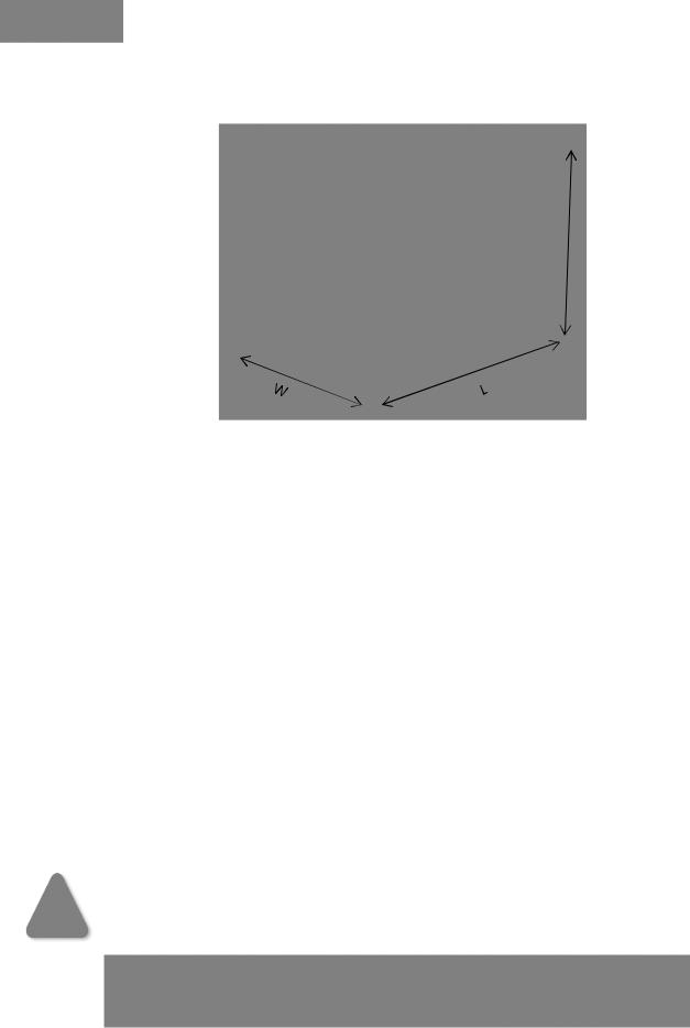
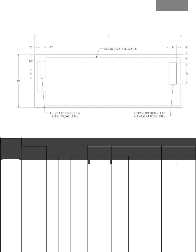
4. DIMENSIONAL DATA
H
Figure 2
|
KAIRAK MODEL |
|
|
DIMENSION (INCH) |
|
||
|
|
|
|
||||
|
|
|
|
|
|
|
|
|
NUMBER |
|
L |
|
W |
|
H |
|
KMR-4 |
|
48 |
|
48 |
|
54 |
|
|
|
|
|
|
|
|
|
KMR-6 |
|
72 |
|
48 |
|
54 |
|
|
|
|
|
|
|
|
|
KMR-8 |
|
96 |
|
48 |
|
54 |
|
|
|
|
|
|
|
|
|
KMR-10 |
|
120 |
|
48 |
|
54 |
|
|
|
|
|
|
|
|
|
KMR-12 |
|
144 |
|
48 |
|
54 |
|
|
|
|
|
|
|
|
|
KMR-14 |
|
168 |
|
48 |
|
54 |
|
|
|
|
|
|
|
|
|
KMR-16 |
|
192 |
|
48 |
|
54 |
|
|
|
|
|
|
|
|
|
KMR-18 |
|
216 |
|
48 |
|
54 |
|
|
|
|
|
|
|
|
|
KMR-20 |
|
240 |
|
48 |
|
54 |
|
|
|
|
|
|
|
|
CAUTION: Installation clearance: a minimum of 3 feet on all sides.
NOTE: Refrigeration lines are stubbed at right end of Rack. Electrical lines are stubbed at left end of Rack. Control Panel adds 10” to length of unit.
PAGE 8 |
KAIRAK REMOTE RACK SYSTEM |
|
REV: 2-2014 |
5. INSTALLATION
5.1 RECEIPT AND INSPECTION OF EQUIPMENT
The utmost care has been taken in crating your Kairak Remote Rack system to protect it against damage in transit. Carefully inspect your unit for damage that may have occurred during delivery. If damage is detected, you should save all crating materials and make a note on the carrier’s Bill of
Lading describing the damage. Pictures should be taken to document the damage. A freight claim should be filed immediately with the freight carrier. If damage is later noted, either during or immediately after installation, contact the respective carrier and file a freight claim. There is a fifteen (15) day limit to file a freight damage claim with most carriers. Under no condition may a damaged unit be returned to Kairak without first obtaining written permission (return authorization). Any damage must be documented and reported to Kairak. The documentation as well as pictures showing damage should be included. Contact Kairak customer care at (800) 8331106.
5.2 LIFTING INSTRUCTIONS
The Kairak Remote Rack system is a heavy piece of machinery and can weigh from approximately 500 to 10, 000 lbs. Careful consideration of lifting procedures should be made before the unit is lifted by any means. Cables or other load-bearing devices must not be allowed to press against the unit frame body, piping, electrical conduit or the motor control panel. The only area of the unit designed to carry the lifting load is the base. Lifting loads should be distributed evenly around the base to avoid twisting. When lifting the unit by crane, the lifting space provided in the lower portion of the base frame is the recommended attachment points for the lifting cables. (See Figure 3). A spreader bar or similar device should be used to prevent the lifting cables from contacting the unit
KAIRAK REMOTE RACK SYSTEM |
PAGE 9 |
REV: 2-2014
SPREADER
SPREADER
PLATFORM
Figure 3
WARNING: CABLES OR OTHER LOAD-BEARING DEVICES MUST NOT BE ALLOWED TO PRESS AGAINST THE UNIT FRAME BODY, PIPING, ELECTRICAL CONDUIT OR THE MOTOR CONTROL PANEL.
5.3 LOCATION AND VENTILATION
The Kairak Remote Rack unit must be located in an area which allows easy access for installation and service of all electrical lines, refrigeration piping and any accessory equipment. The unit must be level to insure proper lubrication. A minimum of 3 feet clearance must be provided on all sides of the unit.
Equipment should be mounted on a smooth, hard, level surface. Mounting surface should be rigid and provisions should be made to prevent noise transmission (structural) to surrounding areas. Air
PAGE 10 |
KAIRAK REMOTE RACK SYSTEM |
|
REV: 2-2014 |
cooled equipment should not be installed under low structural overhangs which can cause condenser air recirculation restriction. Two units side by side should have a minimum of 1 ½ unit width between them. Care should be taken to prevent air from other sources from entering condenser if this air is at an elevated temperature.
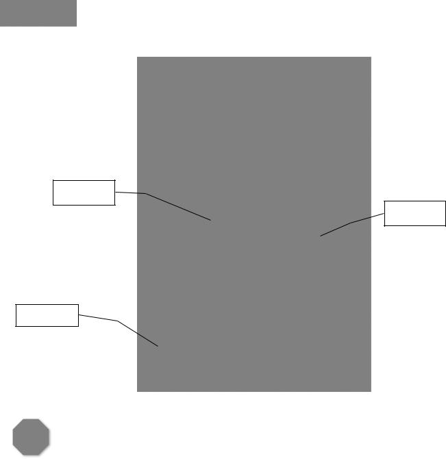
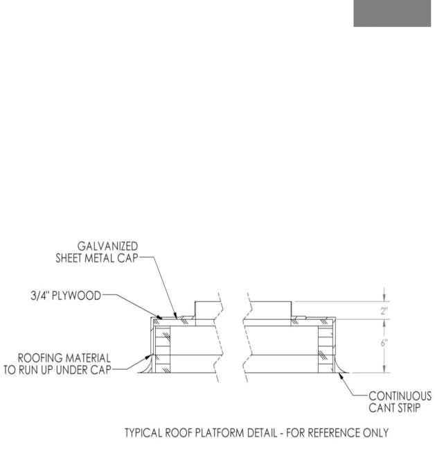
5.4 ROOF PLATFORM REQUIREMENTS
The suggested roof platform requirements are shown in Figure 4. The location and installation of all equipment should be in accordance with all local code requirements. The unit can usually be placed directly on the roof platform since each compressor is mounted on vibration isolation pads. For light roof construction vibration isolation pads can be used underneath the supporting frame.
Figure 4
5.5PITCH POCKET
A.9” x 24” pitch pocket must be provided for refrigeration lines. After lines are installed, backfill opening with hot pitch and make sure there are no leaks.
5.6ELECTRICAL
To insure operation of equipment and reduce the possibility of electrical power interruption, the
following precautions must be observed:
KAIRAK REMOTE RACK SYSTEM |
PAGE 11 |
REV: 2-2014

A.All electrical must be done in accordance with the National Electrical Code and existing local codes.
B.The power supply must be the same as that which appears on the data plate of the motors.
C.An adequate power supply must be provided.
D.Voltage fluctuations in excess of +/- 10% should be corrected.
E.120 volts, 1 phase, 60 Hz power supply must be provided for walk-in cooler.
F.All unit wiring terminals should be checked for tightness before power is applied to the equipment.
G.When wiring is completed, fan motors should be checked for proper rotation. All fan motors of multiple fan equipment have been factory wired to operate with the same rotation. If rotation is found incorrect, reverse two of the three leads on the main incoming power.
Before starting a Kairak Remote Rack System, check that all breakers and motor protective devices are in place and that all wiring is secure. A wiring diagram for troubleshooting the unit is included on the cover.
PAGE 12 |
KAIRAK REMOTE RACK SYSTEM |
|
REV: 2-2014 |
5.7 PLATFORM DIMENSIONS
|
|
Figure 5 |
|
|
|
KAIRAK REMOTE RACK SYSTEM DIMENSIONS |
ROOF PLATFORM DIMENSIONS (INCHES) |
||||
KAIRAK |
|
CONDENSER |
OVERALL |
CURB |
|
MODEL |
|
||||
DIMENSION (INCH) |
FAN MOTORS |
PLATFORM |
OPENING |
||
ENCLOSURE |
|||||
NUMBER |
|
208V/1PH/60Hz |
|
|
|
|
|
|
|
|
|
|
L |
|
W |
|
H |
|
|
QTY |
|
|
L |
|
W |
|
H |
|
|
|
A |
|
|
B |
|
|
|
|
|
WEIGHT (LBS) |
|
|
|
|
|
|
|
|
|
|
|
|
|
|
|
|
|
|
|||||||||
|
KMR-4 |
440 |
48 |
48 |
54 |
2 |
62 |
57 |
6 |
20 |
|
8 |
|
|
||||||||||||||||
|
|
|
|
|
|
|
|
|
|
|
|
|
|
|
||||||||||||||||
|
KMR-6 |
640 |
72 |
48 |
54 |
2 |
86 |
57 |
6 |
20 |
|
8 |
|
|
||||||||||||||||
|
|
|
|
|
|
|
|
|
|
|
|
|
|
|
||||||||||||||||
|
KMR-8 |
695 |
96 |
48 |
54 |
3 |
110 |
57 |
6 |
20 |
|
8 |
|
|
||||||||||||||||
|
|
|
|
|
|
|
|
|
|
|
|
|
|
|
||||||||||||||||
|
KMR-10 |
870 |
120 |
48 |
54 |
4 |
134 |
57 |
6 |
23 |
|
8 |
|
|
||||||||||||||||
|
|
|
|
|
|
|
|
|
|
|
|
|
|
|
||||||||||||||||
|
KMR-12 |
1000 |
144 |
48 |
54 |
5 |
158 |
57 |
6 |
23 |
|
8 |
|
|
||||||||||||||||
|
|
|
|
|
|
|
|
|
|
|
|
|
|
|
||||||||||||||||
|
KMR-14 |
1240 |
168 |
48 |
54 |
5 |
182 |
57 |
6 |
23 |
|
8 |
|
|
||||||||||||||||
|
|
|
|
|
|
|
|
|
|
|
|
|
|
|
||||||||||||||||
|
KMR-16 |
1440 |
192 |
48 |
54 |
6 |
206 |
57 |
6 |
30 |
|
8 |
|
|
||||||||||||||||
|
|
|
|
|
|
|
|
|
|
|
|
|
|
|
||||||||||||||||
|
KMR-18 |
1600 |
216 |
48 |
54 |
7 |
230 |
57 |
6 |
30 |
|
8 |
|
|
||||||||||||||||
|
|
|
|
|
|
|
|
|
|
|
|
|
|
|
||||||||||||||||
|
KMR-20 |
1820 |
240 |
48 |
54 |
8 |
254 |
57 |
8 |
30 |
|
8 |
|
|
||||||||||||||||
|
|
|
|
|
|
|
|
|
|
|
|
|
|
|
|
|
|
|
|
|
|
|
|
|
|
|
|
|
|
|
KAIRAK REMOTE RACK SYSTEM |
PAGE 13 |
REV: 2-2014
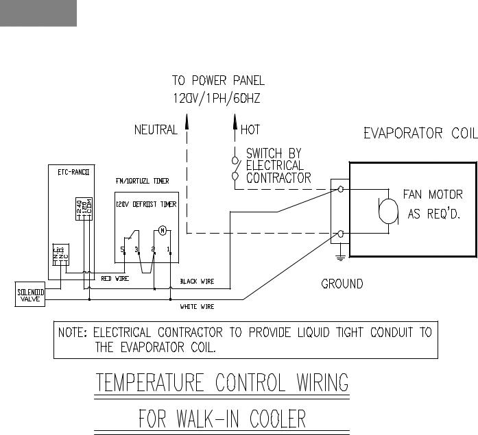
5.8 WIRING DIAGRAM – WALK IN COOLER
Figure 6
PAGE 14 |
KAIRAK REMOTE RACK SYSTEM |
|
REV: 2-2014 |

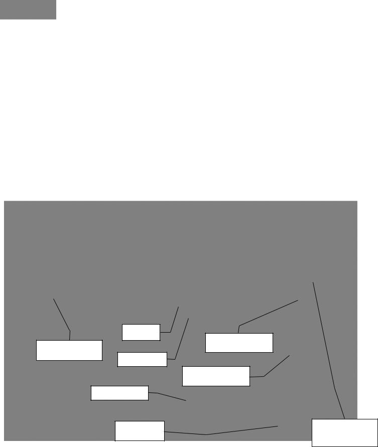
5.9 WIRING DIAGRAM – WALK IN FREEZER
Figure 7
KAIRAK REMOTE RACK SYSTEM |
PAGE 15 |
REV: 2-2014
6. REFRIGERATION
6.1 PIPING
Connect suction and liquid lines with the evaporator coils and condensing unit on the roof. Leave access tubing in the attic space and backfill opening with hot pitch after installation so that there are no leaks. Precautions must be taken to insure no foreign material enters the pipes during installation.
All piping must be supported with hangers that can withstand the combined weight of tubing, insulation, valves and fluid in the tubing.
Refrigeration piping must be in compliance with the National and local code and apply good refrigeration standard practice for proper operation of the system.
PLATFORM
CURBED OPENING FOR
CURBED OPENING REFRIGERATION LINES
FOR ELECTRICAL LINES
FINISHED ROOF
P–TRAP EVERY 10 FT.
EVAPORATOR COIL
P–TRAP @
SUCTION RISER
INVERTED TRAP AT END OF RISER
Figure 8
PAGE 16 |
KAIRAK REMOTE RACK SYSTEM |
|
REV: 2-2014 |

6.2STANDARD PIPING PROCEDURES
A.Refrigeration pipes should be sized properly. (See Chart 5)
B.For the point of connection at the Remote Rack unit and the condensing unit or evaporator fixture, the pipe sizes may not be the same size as the interconnecting pipes.
C.Use only dehydrated copper tubing listed for refrigeration grade and application. Only long radius elbows are to be used.
D.Use a minimum of 15% silver solder alloy on suction and liquid lines. Dry nitrogen should be passed through when brazing the lines at a low pressure to eliminate oxidation and scaling.
E.Suction lines should be sloped ½” for every 10 feet towards the remote rack. “P” traps should be installed at the bottom of each suction riser and at least every 10 feet of the riser. Inverted traps are also necessary on the top of the risers. This will allow good oil return for the compressors. Double risers are highly recommended on the large suction lines with a high capacity and parallel system, ran parallel, to compensate during minimum load and full load.
F.Suction lines should be insulated using listed insulation and plenum rated. The installer must select the correct thickness of the insulation material. At a minimum, insulation should have a ¾” wall thickness. Any pipe insulation located outdoors should be covered and waterproofed to protect it from rain and UV.
G.Installers should provide and add isolation valves on suction and liquid to be able to isolate and service evaporator coils in walk-ins, fixtures, reach-ins, prep tables, under counters or any other units.
6.3LEAK TESTING
After all refrigeration lines are connected, the entire system must be leak tested. Particular care should be given to those parts which will be inaccessible at a later date. Pressurize pipes with nitrogen at 300 PSI for at least 48 hours. The use of an electric leak protector is highly recommended because of its greater sensitivity to small leaks.
KAIRAK REMOTE RACK SYSTEM |
PAGE 17 |
REV: 2-2014

6.4 SYSTEM EVACUATION
With refrigerant piping completed and leak tested, equipment is ready to evacuate. Do not use compressor to evacuate system. A quality vacuum pump of 500 microns vacuum is necessary for adequate and dependable system vacuum. Moisture in a refrigeration system can cause corrosion, expansion valve freeze-up and oil sludge.
Attach vacuum pump to both high and low side of the system through compressor service valves and evacuate to 500 microns (all service valves*, hand valves and solenoids must be open during evacuation). It is suggested that the vacuum pump be run for a period of time after vacuum has been reached.
*Service valves are back setting valves and must be mid-position to open both sides of the system.
6.5 SYSTEM CHARGING (LESS FLOODED HEAD PRESSURE CONTROL)
With system wired, piped and evacuated, the unit is ready for refrigerant charging. All charging lines and manifolds must be evacuated prior to admitting refrigerant into the system to prevent contaminating the system with non-condensable.
Connect charging line to receiver outlet valve and admit “liquid” refrigerant into high side of system until flow stops due to pressure equalization between high side and drum pressure. Backseat outlet valve and disconnect charging line.
Connect charging line to compressor suction service valve and admit “vapor” into low side system.
Energize equipment and continue to admit vapor into low side of system until liquid line sight glass clears, indicating a fully charged system. It may be necessary to defeat low pressure control on initial start to prevent nuisance trip until low side pressure is above cut out point of control.
6.6 SYSTEM CHARGING (WITH FLOODED HEAD PRESSURE CONTROL)
Initial charging is the same as outlined in “Less flooded head pressure control”.
Do not adjust control valves. These are either factory preset or non-adjustable, depending on size. The non-adjustable valves are set at 180 psi for by pass.
PAGE 18 |
KAIRAK REMOTE RACK SYSTEM |
|
REV: 2-2014 |
Set unloaders (if supplied) to load compressors to 100% while charging. Add additional refrigerant to bring total up to required charge as listed on the system ETL label located on the control panel or the system drawings provided. For the low side charge, energize equipment and continue to admit vapor until liquid line sight glass clears indicating a fully charged system. It may be necessary to defeat low pressure control on initial start to prevent nuisance trip until low side pressure is above cut out point of control.
This is a continuation of “system charging” and must be performed before equipment can be left operating and unattended. This will involve checking and adjusting of all safety and operating controls (pressure and temperature controls have not been set at the factory). Adjust and confirm that the settings are correct and that all controls function properly. Do not attempt to function safety controls without some means of stopping compressor in event of extreme high or low pressure conditions that could damage the equipment. If controls fail to function at set points, determine cause and correct. Jumping any safety control other than for testing purposes is dangerous to personnel and equipment and nullifies equipment warranty.
Energize crankcase heaters and allow a minimum of 24 hours operation before a compressor start.
A.High Pressure Control -connect a gauge to the compressor discharge service valve. Stop the condenser airflow by stopping fans on air cooled equipment or restricting water flow on water cooled equipment. Control should open immediately when discharge pressure reaches control set point.
B.Low Pressure (Pump-Down) Control – Connect a gauge to the compressor suction service valve. Throttle receiver outlet valve to lower suction pressure at compressor. Compressor should pump-down and be de-energized when suction pressure reached
“cut-out” setting of control. Open receiver outlet valve and observe rise in pressure at compressor suction connection. Compressor should be energized when pressure reaches “cut-in” setting of control.
C.Oil Pressure Control – Copeland Compressor – jumper between terminals T1 and T2 of the oil pressure safety control. Compressor should run approximately 120 seconds and cycle off. Remove jumper and reset control. Check operating oil pressure. This is the differential between oil pump discharge pressure and suction pressure and should be a minimum of 10 psig. After several hours running time check oil level in compressor, acceptable oil level is approximately ¼ on sight glass.
KAIRAK REMOTE RACK SYSTEM |
PAGE 19 |
REV: 2-2014

6.7 THERMAL EXPANSION VALVE
Adjust superheat setting to job requirements. To correctly determine superheat:
A.Measure the temperature of the suction line at the point the bulb is clamped.
B.Obtain the suction pressure that exists in the suction line at the bulb location by either of the following methods:
If the valve is externally equalized, a gauge in the external equalizer line will indicate the desired pressure directly and accurately.
OR
Read the gauge pressure at the suction valve of the compressor. Add the estimated pressure drop through the suction line between bulb location and compressor suction valve to the gauge pressure.
The sum of the gauge reading and the estimated pressure drop will equal the approximate suction line pressure at the bulb.
C.Convert the pressure obtained (above) to saturated evaporator temperature by using a temperature-pressure chart.
D.Subtract the temperature reading of the suction line at the point of the bulb and the converted saturated evaporator temperature from the chart. The difference is superheat.
E.(Figure 9) illustrates a typical example of superheat measurement on a refrigeration system using refrigerant 22. The temperature of the suction line at the bulb location is read at 52°F. The suction pressure at the evaporator bulb location is read at 68 psig which is equivalent to a 40°F saturation temperature. 40°F subtracted from 52°F = 12°F superheat.
PAGE 20 |
KAIRAK REMOTE RACK SYSTEM |
|
REV: 2-2014 |

Figure 9
6.8 HOT GAS BYPASS
(If Supplied) connect gauge to compressor suction service valve. Throttle receiver outlet valve to lower suction pressure at compressor. Hot gas regulator should begin to open as suction pressure approaches design suction pressure. This should be done before unit has bulled down to design condition.
6.9 FAN CYCLE CONTROL
The fan cycle control is located at the discharge lines or at the compressor discharge service valve. The non-adjustable fan cycles are set to close at 260 psi and open at 190 psi. The adjustable fan cycle control must be set and adjusted per the factory settings as indicated in the system rack drawings.
7. START-UP PROCEDURE
After the installation has been completed, before beginning start-up procedures the following checks should be performed:
KAIRAK REMOTE RACK SYSTEM |
PAGE 21 |
REV: 2-2014

7.1CONDENSING UNITS
A.Check electrical connections to insure all connections are properly tightened. Verify supplied voltage rating and phase meet system requirements as listed on the system ETL label located on the control panel.
B.Check the motor-compressor oil level before start-up. The oil level should be at or slightly above the center of the sight glass. To add oil, use only manufacturer recommended oil as noted on each compressor tag.
C.Insure that the rubber grommets are installed under the motor-compressor mounting nuts and that the motor compressor rides freely on its mounting vibration isolators.
D.Check the high and low pressure controls and all other safety controls. Adjust if necessary.
E.Check the walk-in cooler and freezer thermostats for correct operation. Confirm solenoids are opening and closing as required.
F.Tags are provided to indicate refrigerant used in the system.
G.The instruction manual, bulletins, tags, etc., are attached to the unit and should be placed inside the electrical panel for future reference.
H.Observe system pressures during initial operation. Do not add oil while the system is short of refrigerant unless the oil level is dangerously low.
I.Open all isolation valves, including all service valves at the compressors suction and discharge and at the receivers. Check that all Rotalock nuts are tightened securely. Tighten all valves to avoid leaks after start up.
WARNING: DO NOT OVERCHARGE WITH OIL.
7.2EVAPORATOR COIL – BEFORE START UP
A.Make sure system is wired correctly. Verify voltage rating.
B.Check to make sure all electrical terminals are tight.
PAGE 22 |
KAIRAK REMOTE RACK SYSTEM |
|
REV: 2-2014 |

C.Check fan set screws to confirm they are tight
D.Check unit to confirm it is mounted securely using all hangers and is as level as possible.
E.Make sure the drain connection is tightened to the drain line securely.
F.Pour water into the drain pan to check for complete drainage of the drain pan and drain line.
7.3EVAPORATOR COIL – AFTER START UP
A.On initial start-up for the freezer evaporator coil, the fans will not start until the coil temperature reaches approximately 25°F.
B.Check the expansion valve superheat setting. It is important that the valve is set properly for efficient operating and even frost formation.
C.Make sure the drain line heater is working properly.
D.Heavy moisture loads are usually encountered when starting a system for the first time. This will cause a rapid frost build-up that will need to be closely watched. Manually defrost the unit as required.
E.Observe the system as it goes through the first defrost cycle to make sure the timer, defrost heaters, termination thermostat and other system components function properly.
7.4OPERATIONAL CHECK-OUT
Only after the system has operated for at least two hours at normal operating conditions without any indications of malfunctions should it be allowed to operate overnight on automatic controls. A thorough re-check of the entire system operation should be made as follows:
A.Check the motor-compressor head and suction pressure. If the pressures are not within the system design limits, determine why and take corrective action.
B.Check the liquid line sight glass and expansion valve operation. If there are indications that more refrigerant is required, leak test all connections and system components and repair any leak before adding refrigerant.
KAIRAK REMOTE RACK SYSTEM |
PAGE 23 |
REV: 2-2014
 Loading...