

Kairak KE Installation Manual
Pit construction diagram 00705880C
Breite
Länge
AL
30 cm
30 cm
min 10
min 10
A
A
Schnitt A-A
Höhe
Schnitt A-A
Höhe
Standard equipmentStandard equipment
Standard equipment
Standard equipmentStandard equipment
Pit construction diagram 00705880C
METTLER TOLEDO MultiRange
Dry and wet pit (Part1)
ME/MES1500/3000sk
KE/KES1500/3000sk
KE/KES1500/3000skx
© Mettler-Toledo (Albstadt) GmbH Printed in Germany 11/01 english
1. Determine location of weighing platform
Note maximum static load:
with central load:
4500 kg
with lateral load:
3000 kg
with corner load of
one side:
1500 kg
Load-bearing capacity of pit base:
min. 1700 kg / 25 cm²
3. Prepare framework pit
Excavate the framework pit according to the type of
weighing platforms.
Dry pit: depth approx. 25 cm
Wet pit: depth appr. 30 cm
2 Pit angle, lengthwise
2 Pit angle, crosswise
4 Hex bolts M12x30 DIN 933
4 Nuts M12 DIN 934
6 Clamping plates (KE.../KES...)
8 Clamping plates (KES.../MES)
1 Pit construction diagram
2. Determine location of terminal
length x widthlength x width
length x width
length x widthlength x width
ME.../KE...ME.../KE...
ME.../KE...
ME.../KE...ME.../KE...
MES.../KES...MES.../KES...
MES.../KES...
MES.../KES...MES.../KES...
190 x 165 cm190 x 165 cm
190 x 165 cm
190 x 165 cm190 x 165 cm
190 x 190 cm190 x 190 cm
190 x 190 cm
190 x 190 cm190 x 190 cm
Set up terminal to ensure
good accees
Length of connection cable
terminal 5 m
METTLER TOLEDO MultiRange
Dry and wet pit (Part2)
ME/MES1500/3000sk
KE/KES1500/3000sk
KE/KES1500/3000skx
5. Dimension drawings
Dry pitDry pit
Dry pit
Dry pitDry pit
ME.../KE...ME.../KE...
ME.../KE...
ME.../KE...ME.../KE...
MES.../KES...MES.../KES...
MES.../KES...
MES.../KES...MES.../KES...
length x width x heighlength x width x heigh
length x width x height
length x width x heighlength x width x heigh
152 x 127 x 20 cm152 x 127 x 20 cm
152 x 127 x 20 cm
152 x 127 x 20 cm152 x 127 x 20 cm
152 x 152 x 22 cm152 x 152 x 22 cm
152 x 152 x 22 cm
152 x 152 x 22 cm152 x 152 x 22 cm
height
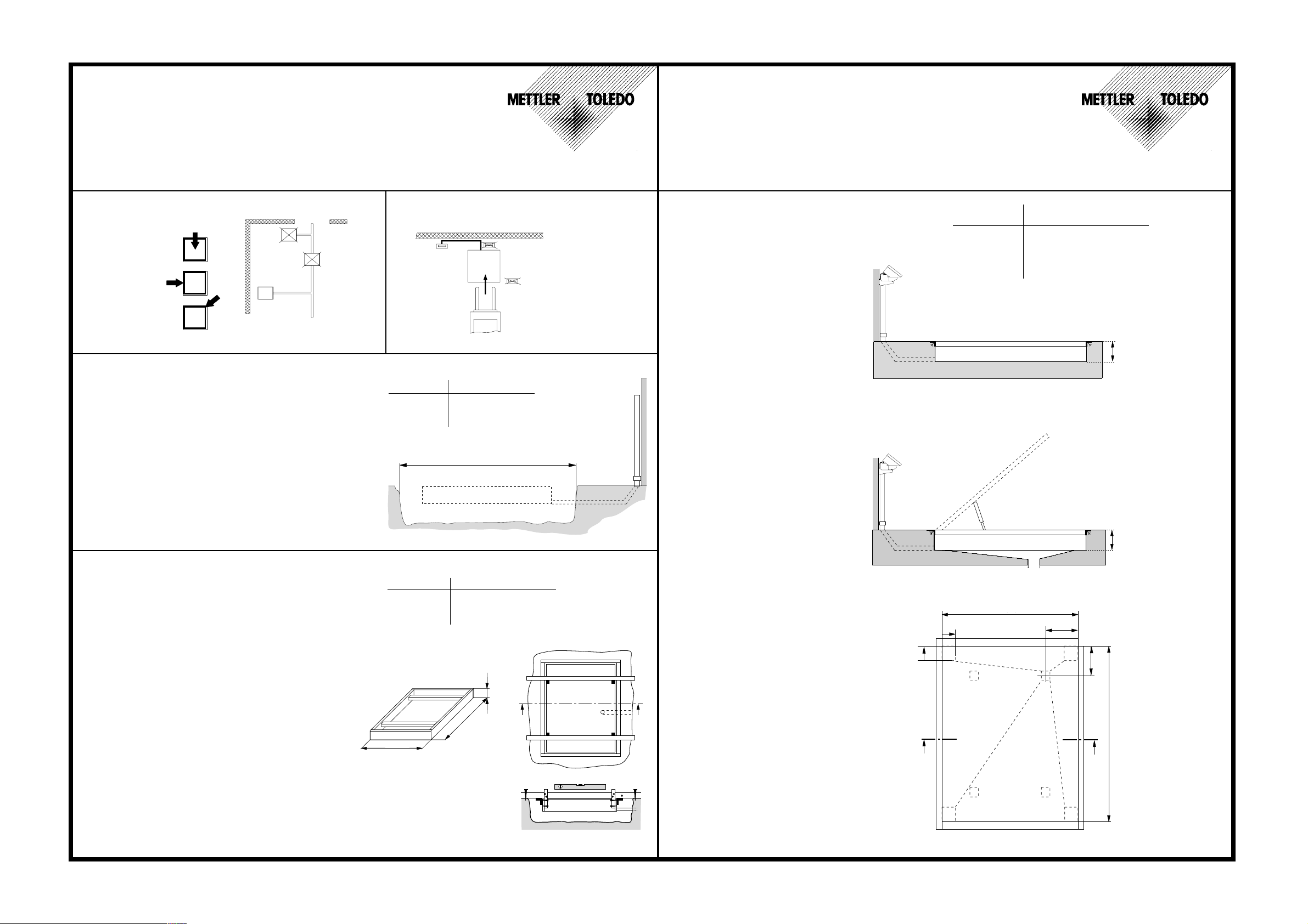
Section A-A
Excavate channel of depth approx. 20 cm for cable conduit.
The cable conduit ends in the base of the pit (see ilustration).
Pipe diameter min. 40 mm.
Do not use a right-angled pipe, rather two pipes of 45°.
4. Concrete forming
Assemble steel pit frame.
When tighening the bolts ensure that the frame is flat.
Check that the frame is rectangular (same width
across corners).
Prepare stable wooden frame (see sketch for dimensions).
The steel frame must fit the wooden exactly.
Install wooden frame together with steel frame in the
framework pit.
The steel frame must be leveled exactly.
When concreting ensure that the wooden frame
remains in place!
Position emply conduits for cable connection correctly.
ME.../KE...ME.../KE...
ME.../KE...
ME.../KE...ME.../KE...
MES.../KES...MES.../KES...
MES.../KES...
MES.../KES...MES.../KES...
127 cm
width
length x width
Länge x Breite
length x width x heightlength x width x height
length x width x height
length x width x heightlength x width x height
152 x 127 x 20 cm152 x 127 x 20 cm
152 x 127 x 20 cm
152 x 127 x 20 cm152 x 127 x 20 cm
152 x 152 x 22 cm152 x 152 x 22 cm
152 x 152 x 22 cm
152 x 152 x 22 cm152 x 152 x 22 cm
20 cm
height
152 cm
length
x
Wet pitWet pit
Wet pit
Wet pitWet pit
height
Section A-A
width
DWPDWP
DWP
DWPDWP
DWP Drain Water PitDWP Drain Water Pit
DWP Drain Water Pit
x
DWP Drain Water PitDWP Drain Water Pit
length
Wet pit:
After pit base has set and the formwork removed, concrete
the supports for the weighing platfrom.
Section X-X
Schnitt X-X
 Loading...