

Operating Instructions
Powador
XP500/550-OD-TL
English Version
GM06201i

Operating Instructions
- English Version -
Powador XP500/550-OD-TL
General Instructions for Installers and Operators
1 General Notes ........................................4
1.1 About this documentation .......................4
1.2 Name plate ..............................................6
1.3 Intended use ............................................ 7
1.4 Safety instructions .................................... 7
2 Service ....................................................8
3 Unit Description ....................................9
3.1 Technical Data .......................................... 9
3.2 Dimensions ............................................ 11
3.3 Components inside the inverter .............. 13
4 Transportation and Delivery .............. 15
4.1 Delivery .................................................. 15
4.2 Transportation ........................................ 15
4.3 Centre of Gravity of the Inverter ............. 16
5 Storage/Installation/Start-up .............18
5.1 Storage ................................................. 18
5.2 Transporting the unit to the installation
location ................................................. 18
5.3 Selecting the installation location ........... 20
5.4 Electrical connection .............................. 21
5.5 Start-up ................................................. 27
5.6 Operation .............................................. 30
5.7 User interface ......................................... 34
5.8 Software upgrade .................................. 35
6 Faults and Warnings ...........................43
6.1 Warning ................................................. 43
6.2 Fault .......................................................44
6.3 Solution for Error code ........................... 46
7 Maintenance/Cleaning........................54
7.1 Maintenance intervals ............................ 55
7.2 Cleaning and replacing the fi lters ...........56
7.3 Cleaning and Replacing the fans .............58
8 Parameters ...........................................60
8.1 PV Array parameters ..............................60
8.2 Inverter parameters ................................ 62
8.3 Grid parameters ..................................... 62
8.4 Time Parameters..................................... 71
8.5 Digital Parameters ................................. 71
8.6 Analog Parameters ................................ 72
8.7 Controller Parameters ............................ 73
9 User interface ......................................90
9.1 Digital input/output ................................ 91
9.2 RS485 interface ...................................... 94
9.3 Analog input ..........................................96
10 Overview circuit Diagram ...................99
11 Decommissioning/Dismantling ........100
12 Disposal .............................................101
5.9 Connecting to inverter via Wi-Fi in local .38
Operating Instructions Powador XP500/550-OD-TL Page 3

General Notes
1 General Notes
1.1 About this documentation
WARNING
Improper handling of the inverter can be dangerous
› You must read and understand the operating instructions before you can install and
use the inverter safely.
1.1.1 Other applicable documents
During installation, observe all assembly and installation instructions for components and other parts of the
system. These instructions are delivered together with the respective components and other parts of the system.
Some of the documents which are required to register your photovoltaic system and have it approved are
included with the operating instructions.
1.1.2 Retention of documents
These instructions and other documents must be stored near the system and be available whenever they are
needed.
Page 4 Operating Instructions Powador XP500/550-OD-TL
General Notes
1.1.3 Description of safety instructions
DANGER
Imminent danger
Failure to observe this warning will lead directly to serious bodily injury or death.
WARNING
Potential danger
Failure to observe this warning may lead to serious bodily injury or death.
CAUTION
Low-risk hazard
Failure to observe this warning will lead to minor or moderate bodily injury.
ATTENTION
Hazard with risk of property damage
Failure to observe this warning will lead to property damage.
NOTE
Useful information and notes.
Operating Instructions Powador XP500/550-OD-TL Page 5

General Notes
1.1.4 Symbols used in this document
General danger symbol Information
High voltage Risk of burns
1.1.5 Description of actions
Action
Perform this action
(Possibly additional actions)
The result of your action(s)
1.1.6 Abbreviations
MMI Man Machine Interface RPC Remote Power Control
PEBB Power Electronics Building Block APS Anti-islanding method
PSI PEBB Signal Interface board ACI
protocol
ASI Analog Signal Interface board PLL Phase Locked Loop
GUI Graphic User Interface XCU XP Control Unit (Inverter control system)
MPPT Maximum Power Point Tracking CAN Controller Area Network
MPP Maximum Power Point FPGA Field-Programmable Gate Array
Vdc PV Voltage DSP Digital Signal Processor
FRT Fault Ride Through ADC Analog to Digital Converter
CEI 0-21 Italia grid code NVSRAM Non-volatile Static RAM
Advanced Communication Interface
(KACO Communication protocol)
1.2 Name plate
The name plate is located on the inside of the left door of the two housing components.
Page 6 Operating Instructions Powador XP500/550-OD-TL

General Notes
1.3 Intended use
The inverter converts the DC voltage generated by the photovoltaic (PV) modules into AC voltage and feeds this
into the power grid. The inverter is built according to the state of the art and recognized safety rules. Nevertheless, improper use may cause lethal hazards for the operator or third parties, or may result in damage to the
unit and other property. The inverter may be operated only with a permanent connection to the public power
grid.
1.4 Safety instructions
DANGER
Lethal voltages are still present in the terminals and lines of the inverter even after
the inverter has been switched off and disconnected!
Coming into contact with the lines and terminals in the inverter will cause serious
injury or death.
Only authorised electricians who are approved by the supply grid operator are allowed
to open, install and maintain the inverter.
› Keep all doors and covers closed when the unit is in operation.
› Do not touch the lines and terminals when switching the unit on and off!
The electrician is responsible for observing all existing standards and regulations.
• Above all, be sure to observe standard IEC 60364-7-712:2002, “Requirements for Special Installations or
Locations – Solar Photovoltaic (PV) Power Supply Systems”.
• Ensure operational safety by providing for proper earthing, conductor dimensioning and appropriate
protection against short circuiting.
• Observe the safety instructions located on the inner sides of the doors.
• Switch off all voltage sources and secure them against being inadvertently switched back on before per-
forming visual inspections and maintenance.
• When taking measurements while the inverter is live:
– Do not touch the electrical connections.
– Remove jewelry from your wrists and fi ngers.
– Make sure that the testing equipment is in good and safe operating condition.
• Stand on an insulated surface when working on the inverter.
• Generally, the inverter may not be modifi ed.
• Modifi cations to the surroundings of the inverter must comply with national and local standards.
Operating Instructions Powador XP500/550-OD-TL Page 7

Service
2 Service
If you need help solving a technical problem with one of our KACO products, please contact our service
hotline. Please have the following information ready so that we can help you quickly and efficiently:
• Inverter type / serial number
• Fault message shown on the display / Description of the fault / Did you notice anything unusual? / What has
already been done to analyse the fault?
• Module type and string circuit
• Date of installation / Start-up report
• Consignment identification / Delivery address / Contact person (with telephone number)
You can find our warranty conditions on our website:
http://kaco-newenergy.de/de/site/service/garantie
From there, you can easily navigate to our international websites by clicking on the appropriate flag. Please
use our website to register your unit within 24 months:
http://kaco-newenergy.de/en/site/service/registrieren
You can also select the appropriate flag on this page to access the website for your own country.
In this manner, you can assist us in providing you with the quickest service possible. In return, you receive two
additional years of warranty coverage for your unit.
Note: The maximum length of the warranty is based on the currently applicable national warranty conditions.
We have prepared a template for complaints. It is located at
http://www.kaco-newenergy.de/en/site/service/kundendienst/index.xml.
Hotlines
Technical troubleshooting Technical consultation
Inverters (*) +49 (0) 7132/3818-660 +49 (0) 7132/3818-670
Data logging and accessories +49 (0) 7132/3818-680 +49 (0) 7132/3818-690
Construction site emergency (*) +49 (0) 7132/3818-630
Customer helpdesk Monday to Friday from 7:30a.m. to 5:30p.m. (CET)
(*) Also on Saturdays from 8:00a.m. to 2:00p.m. (CET)
Page 8 Operating Instructions Powador XP500/550-OD-TL

Unit Description
3 Unit Description
3.1 Technical Data
Model
XP500-OD-TL XP550-OD-TL
DC Input
PV Max. generator Power 600kW 660kW
MPP range 550V ~ 830V
1*
Max. permissible DC voltage
Max. permissible DC current
Voltage ripple < 3%
Current ripple < 4%
Number of DC inputs 6
1091A 1200A
110 0 V
AC Output
Rated power 500kVA 550kVA
Grid voltage 3*370V (±10%)
Rated current 780A 858A
Grid frequency 50Hz / 60Hz
THD of grid current < 3% at rated power
Power factor (cos θ) ≥ 0.99 at rated power
0.8 leading … 0.8 lagging (Adjustable)
Power Consumption
Internal consumption in operation < 1% of rated power (< 1650W)
Internal consumption in stand-by < Approx. 110W
Effi ciency
Max. effi ciency 98.7% 98.7%
Euro effi ciency 98.3% 98.3% (Expectation)
Environment
Operating temperature range -20°C ~ +50°C
Storage temperature range -20°C ~ +70°C
Relative humidity 0 ~ 100% (condensing)
Max. altitude above mean sea level 2000m (as per IEC 62040/3)
3
Cooling Forced Fan (6940m
Audible noise < 70dB
Protection class IP54
Table 1: Electrical data of the inverter
1*
110 0 Vdc is no-load voltage. And max. operating voltage is 1000Vdc
per hour)
Operating Instructions Powador XP500/550-OD-TL Page 9

Unit Description
Model
XP500-OD-TL XP550-OD-TL
Physical Parameters
Dimensions(H/W/D) in mm 2125 / 2600 / 860
Weight 2200kg
Power Density 0.100W/cm
3
Standard
EMC EN61000-6-2, EN61000-6-4, EN61000-3-3, EN61000-3-12
Certifi cates CE
Grid monitoring In accordance with BDEW directive
RD1663
Features
Ground fault detection Yes
Heating Yes
Emergency stop Yes
Overvoltage protection device
AC / DC
Yes / Yes
Overvoltage protection for Ethernet Yes
Overvoltage protection device for
Yes
auxiliary supply
Interfaces
Communication 2 × RS485 / Ethernet / Wi-Fi
Analog input 4 × UAI
Argus box string-monitor RS485
User Digital Input / Output
S0 input / output
4*
3*
Monitoring Device Smart phone (iPhone, Android Phone)
Tab let p c (iPad)
Table 1: Electrical data of the inverter
2*
UAI: User Analog Input. 4 inputs are 1×irradiation input, 1×module temperature, 1×ambient temperature,
1×wind speed. (Option)
3*
UDIO: User Digital Input - 1×Start/Stop signal of the inverter. User Digital Output - 1×External fault signal.
4*
So-impulse signal for energy meter.
2*
1 / 1
1 / 1
Page 10 Operating Instructions Powador XP500/550-OD-TL

Unit Description
3.2 Dimensions
Figure 1: Dimension of the inverter [mm]
Figure 2: Dimension of the inverter base (Bottom View) [mm]
Operating Instructions Powador XP500/550-OD-TL Page 11

Unit Description
Figure 3: Minimum workspace requirements of right side [mm]
Figure 4: Minimum workspace requirements of rear side [mm]
Page 12 Operating Instructions Powador XP500/550-OD-TL

Unit Description
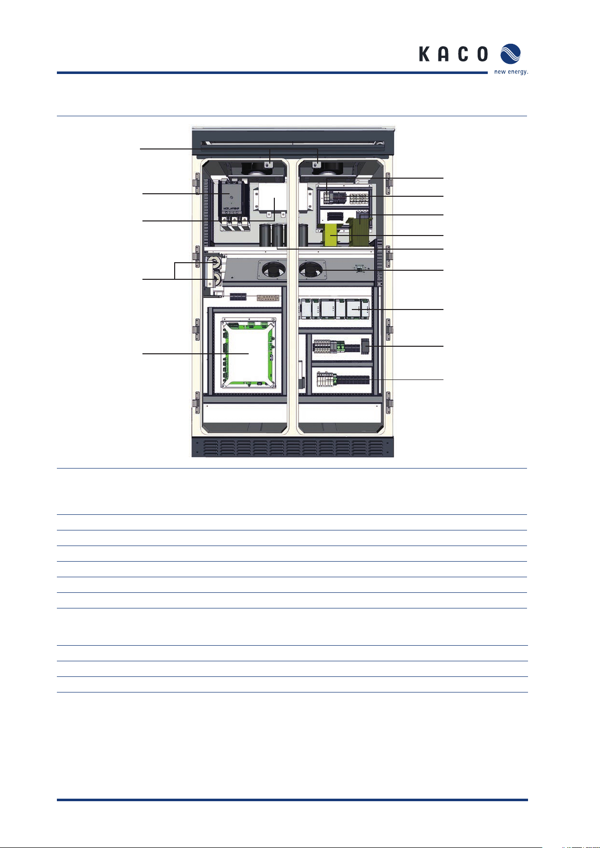
3.3 Components inside the inverter
Left side
13
12
1
2
11
10
9
14
3
4
5
8
15
7
6
Figure 5: Components inside the inverter (left side)
Key
1 EMC 1 (EMC Filter on DC) 8 Overvoltage protection (SP1 - DC Side)
2 GFD (Ground fault detection) 9 Terminals for user connection
3 PSIM (Master control for interface) 10 CB10 (MCCB for use 1100V DC side)
4 CB20 (MCCB for AC grid connection) 11 DC current transformer
5 Overvoltage protection (SP2-AC Side) 12 PEBB (IGBT block)
6 Fuse protection for voltage supply 13 Door sensor
7DC connection
Fuses information
14 F1, F2 1000Vdc, 2A, gPV
15 F1~F12 1100Vdc, 250A, gPV
Operating Instructions Powador XP500/550-OD-TL Page 13
Unit Description
Right side
12
11
13
1
10
2
3
4
5
9
6
8
7
14
Figure 6: Components inside the inverter (right side)
Key
1 FRT Diode 7 EMC Filter for control power
2 CTR (1PH Transformer) 8 XCU Module
3 FRT TR (1PH Transformer) 9 AC current transformer
4 Capacitor for FRT 10 Filter capacitor
5 Fan for Reactor Cooling 11 MC21 (Contactor for grid connection)
6SMPS 12Door sensor
Fuses information
13 F38, F39 600V, 15A, fast-acting
14 F30, F31, F36 600V, 8A, fast-acting
14 F34, F35 600V, 15A, fast-acting
Page 14 Operating Instructions Powador XP500/550-OD-TL

Transportation and Delivery
4 Transportation and Delivery
4.1 Delivery
The inverters leave our factory in proper electrical and mechanical condition. Special packaging ensures that
they are transported safely. The shipping company is responsible for any damage that occurs during transportation.
4.1.1 Scope of delivery
• XP500/550-OD-TL
• Documentation
Check your delivery
Inspect the inverter thoroughly.
Notify the shipping company immediately if you discover any damage to the packaging which indicates
that the inverter may have been damaged or if you discover any visible damage to the inverter.
Send the damage report to the shipping company right away. It must be received by them within six days
following receipt of the inverter. We will be glad to help you, if necessary.
4.2 Transportation
The inverter should be shipped using the original packaging to ensure that it is transported safely.
The inverter cabinets is delivered on a pallet.
Operating Instructions Powador XP500/550-OD-TL Page 15

Transportation and Delivery
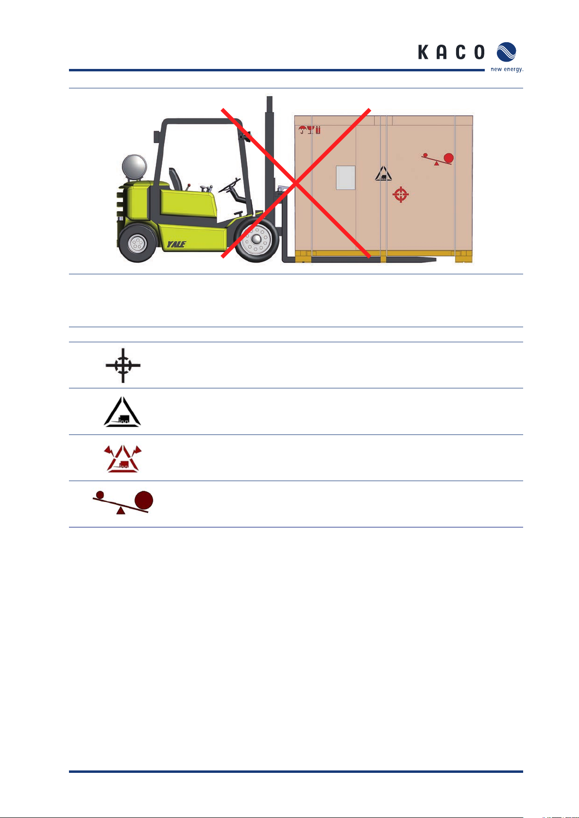
4.3 Centre of Gravity of the Inverter
The centre of gravity of the inverter is not in the middle of the XP500/550-OD-TL. Take this into
consideration when transporting the XP500/550-OD-TL.
The centre of gravity of the inverter is marked with the centre of gravity symbol on the packaging and the enclo-
sure.
Don‘t Lift This Side
Left Front
Figure 7: Centre of gravity by Front side
Center of gravity
Right Back
Figure 8: Centre of gravity by Rear side
Page 16 Operating Instructions Powador XP500/550-OD-TL
Transportation and Delivery
Figure 9: Don’t lift by left side
Symbol Explanation
Centre of gravity of the inverter
Can lift from a this side of inverter
Don’t lift from a this side of inverter
The centre of gravity is not center of inverter
Table 2: Symbols on the Packaging
Operating Instructions Powador XP500/550-OD-TL Page 17
Storage/Installation/Start-up
5 Storage/Installation/Start-up
5.1 Storage
When inverters are in storage, the following conditions are required. If not, this may cause failures. The company will not be responsible for the problems if following condition is not observed.
• The unit should be stored indoor in its original packaging when it’s being stored more than 6 months. If its
original packaging is removed, it should be stored indoor in a cool, dry place.
• When the unit is stored outdoor, please keep the remained original packaging and do not leave the unit out-
side for long term period.
• Storage temperature: -20°C ~ +70°C
• When inverter is stored under high humidity condition for long term period, it has to be dried out suffi ciently
more than 1 day before connecting to the power.
CAUTION
Inverter Storage Caution
Inverters need to be sotred at the correct temperature and correct humidity. If not,
this may cause failures.
5.2 Transporting the unit to the installation location
Once it has arrived at the installation location, the inverter may be transported using the designated eyebolts
or fork-lift. These are located on the top of the inverter housing.
CAUTION
Impact hazard, risk of breakage to the inverter
The centre of gravity is located in the upper part of the inverter.
› Transport the inverter in an upright position.
Transporting the inverter
Transporting the inverter using eyebolts
Transport the inverter in an upright position.
Connection the rope to the two eyebolts on the left.
Connection the rope to the two eyebolts on the right.
Attach both ropes to a hook, making sure that the ropes do not cross each other.
*The rope length: 1650mm over
Position the hook at the middle of the unit.
Transporting the inverter using fork-lift
Remove the front cover of base frame.
Page 18 Operating Instructions Powador XP500/550-OD-TL

Storage/Installation/Start-up
[Eye Nut]
Figure 10: Transporting the unit at the installation location
Figure 11: Transporting the using eyebolts
[Fork Lift]
Operating Instructions Powador XP500/550-OD-TL Page 19
Storage/Installation/Start-up
5.3 Selecting the installation location
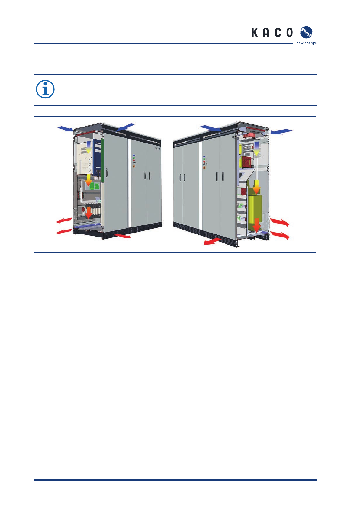
NOTE
The maximum fl ow rate of the cooling air is 6940m³ per hour.
Please keep this value in mind when you select the installation location.
Figure 12: Ventilation for the inverter [mm]
Page 20 Operating Instructions Powador XP500/550-OD-TL
Storage/Installation/Start-up
5.4 Electrical connection
DANGER
Lethal voltages are still present in the terminals and lines of the inverter even after
the inverter has been switched off and disconnected!
Coming into contact with the lines and terminals in the inverter will cause serious
injury or death.
Only authorised electricians who are approved by the supply grid operator may open,
install and maintain the inverter.
› Use extreme caution when working on the unit.
› Disconnect the AC and DC sides.
› Secure them against being inadvertently switched back on.
› Connect the inverter only after the aforementioned steps have been taken.
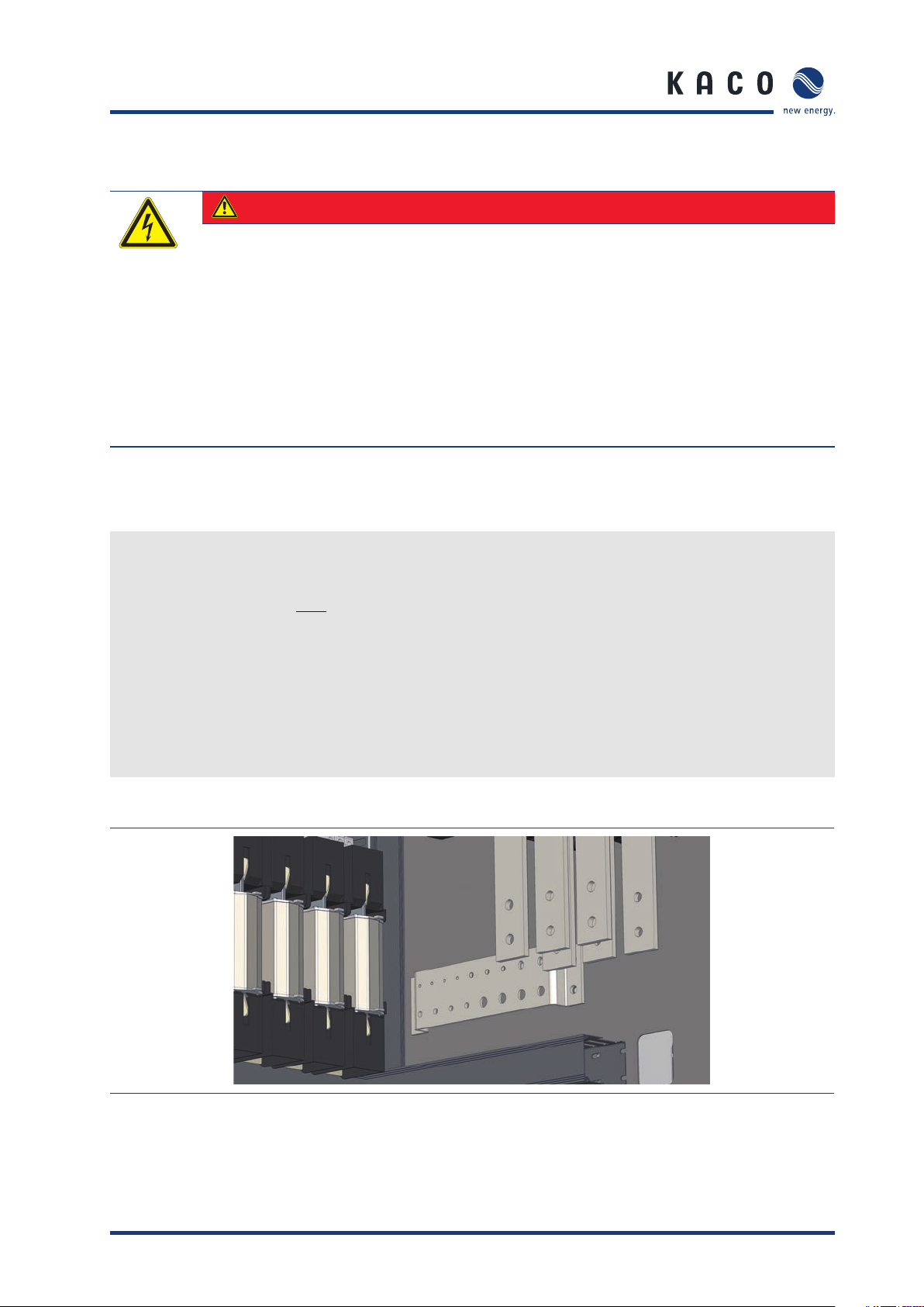
5.4.1 Protective earth connection
Connect the PE bus bars
The PE (protective earth) bus bars are located on the left and right sides of the inverter cabinets.
Connect the wires for “both” PE bus bars.
Earth the inverter
Determine the lay-out of the permanent wiring.
Secure the protective earths (tightening torque for PE terminals: 43Nm). Do not use plug connections.
Check whether all connected cables are securely attached and protected from mechanical forces.
Attach the Plexiglas cover.
Figure 13: PE busbar
Operating Instructions Powador XP500/550-OD-TL Page 21
Storage/Installation/Start-up
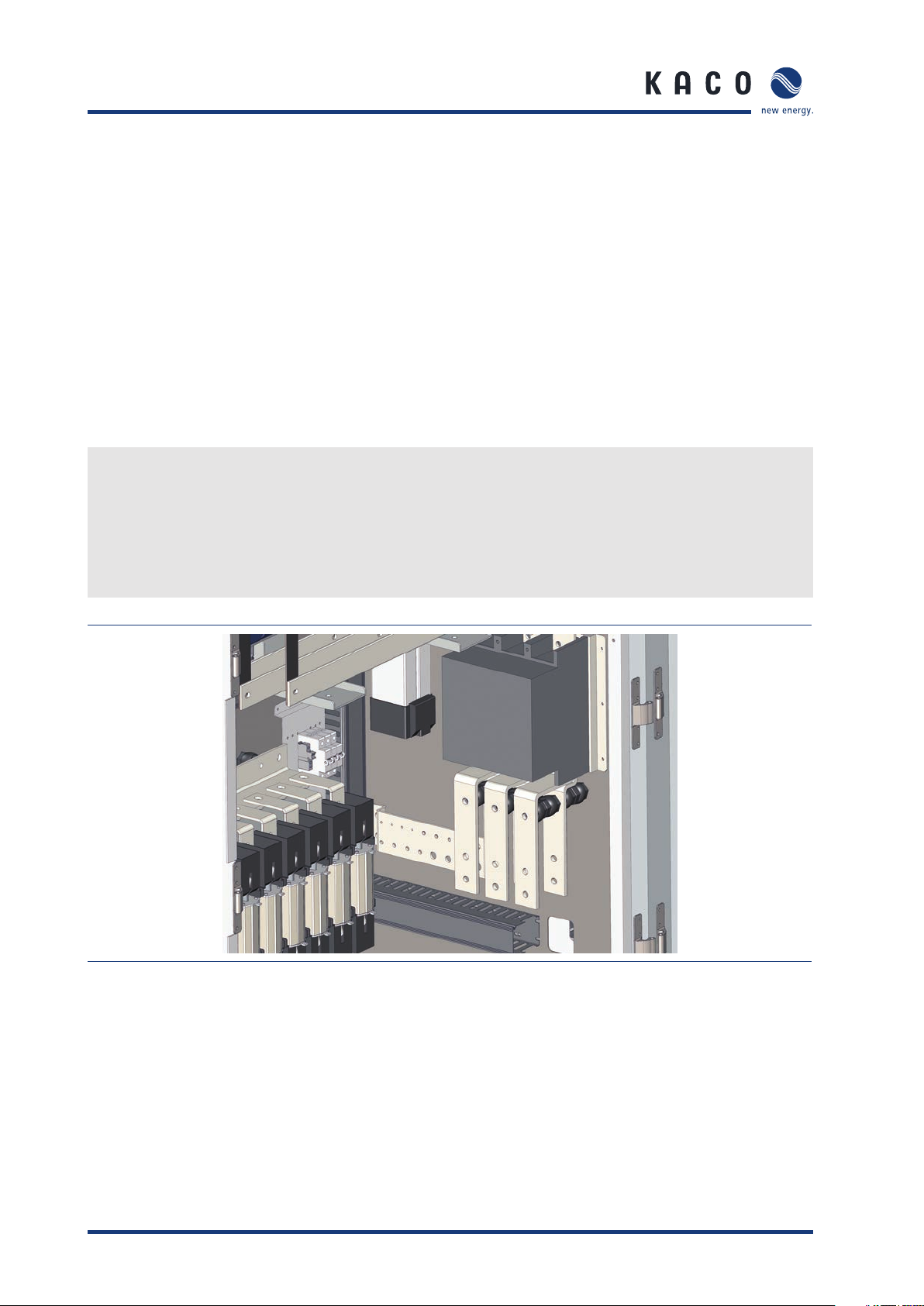
5.4.2 Connecting to the external transformer (AC connection)
The inverter is connected to the power grid using a 3-phase connection. The connection for the power grid is
located in the left side of the housing, at the bottom.
Use the screws that are supplied to screw down the bus bars on both sides.
Connection data
Number of AC Cables (A,B,C) 12
Max. Cable diameter for each phase 240mm2 x 4
Tightening torque for AC terminal connections 43Nm
Cable lug hole size 12mm ~ 14mm
Connect the cables
Each cable corresponds to one phase.
Guide the cables through the opening. Be sure to connect each of the cables to the correct terminal.
Screw down the cables.
Check to make sure that all of the cables are securely attached.
Figure 14: AC connection
Page 22 Operating Instructions Powador XP500/550-OD-TL

Storage/Installation/Start-up
5.4.3 Requirements for cable routing between transformer and inverter
(AC connection)
WARNING
Fire hazard due to overheating of cables
Differing cable lengths result in overheating of the cables.
› All line conductors from the inverter to the transformer must be of the same length.
The followings are requirements for avoiding current imbalances and cable overheating:
• The minimum size of conductor must be designed based on Table24 of IEC62109-1 2010.
• The AC cables must be bundled in a three-phase system (Required to use cables of the equal type, diameter
and length).
• Between the transformer and the inverter there must be four separate cable routes for the AC cables.
• Lay one A, B and C line conductor in each cable route. Ensure that the distance between the cable bundles
at least doubles the cable diameter.
Figure 15: Arrangement of AC cables with 4-cable-per-line conductor (example)
Operating Instructions Powador XP500/550-OD-TL Page 23

Storage/Installation/Start-up
5.4.4 Connection for the PV generator (DC connection)
The DC connection is located in the left side of the housing, at the bottom.
Connection data
Tightening torque for DC terminal connections 43Nm
Max. Cable diameter for each fuse 240mm2 x 2
Cable lug hole size 12mm ~ 14mm
Fuse protection for DC connection 250A, 1100V
6 fuses each for DC+ / DC-
DANGER
Lethal voltages in the PV system
Lethal voltages are present in the PV system.
› Make absolutely sure that the plus and minus poles are properly insulated.
Connect the cables
Each cable corresponds to a specifi c pole.
Connect the cables to the poles. Make sure the polarity is correct.
Screw down the cables.
Check to make sure that all of the cables and seals are securely attached.
NOTE
Please refer to DC Connector Installation manual (NH Fuse Type).
Figure 16: DC connection
NOTE
Use only the optional earthing kit to earth the PV generator.
Page 24 Operating Instructions Powador XP500/550-OD-TL

Storage/Installation/Start-up
5.4.5 Connection for the DC Cable
Figure 17: Bolt & NH Fuse
Item Description
A M12 Bolt Fuse Cover-1
B Flat Washer Fuse Cover-2
CSpring Washer Fuse
D M12 Nut Fuse Base
Table 3: Parameters of operating states
Operating Instructions Powador XP500/550-OD-TL Page 25

Storage/Installation/Start-up
Single-cable Dual-cable
1
2 2
1
3 3
4 4
NOTE
Bolt Torque: 43Nm
Page 26 Operating Instructions Powador XP500/550-OD-TL

Storage/Installation/Start-up
5.5 Start-up
Before starting the inverter, if components are condensed inside the inverter or have been stored in a highly
humid air for a long time, it has to be dried out enough for more than a day, otherwise it will cause failure. After
that the circuit breakers must be switched ON to start the inverter, which also switches on the control circuits.
DANGER
Lethal voltages are still present in the terminals and lines of the inverter even after
the inverter has been switched off and disconnected!
Coming into contact with the lines and terminals in the inverter will cause serious
injury or death.
Only authorised electricians who are approved by the supply grid operator may open,
install and maintain the inverter.
› Keep all doors and covers closed when the unit is in operation.
› Do not touch the lines and terminals when switching the unit on and off!
Switch on the circuit breakers or Fuse
Step Check Action
1 Fuse F30, 31, 34, 35, 36, 38, 39
Circuit breakers CB32, 40
2 Circuit breakers MCB20, 21
Circuit breakers CB20
3 Circuit breaker CB37 Switch on
4Key switch ON Inverter ON
ON Proceed to Step 2
OFF Switch on,
Then proceed to Step 2
ON Proceed to Step 3
OFF Switch on,
Then proceed to Step 3
Then proceed to Step 4
OFF Inverter OFF
NOTE
For NG and PG type Inverter, please do not operate MCB20 arbitrarily.
It may cause failure of the unit.
Operating Instructions Powador XP500/550-OD-TL Page 27

Storage/Installation/Start-up
2
1
1, 2, 3
1
Figure 18: Cabinet (interior view)
Key
1 Fuse F30, 31, 34, 35, 36, 38, 39
Circuit breakers CB32, 40
2 Circuit breakers MCB20, 21
Circuit breakers CB20
3 Circuit breaker CB37
When voltage is present at the inverter, it can be started up. Use the HMI interface to start up the inverter.
The inverter begins operation in a specifi ed sequence. For more information, see section 5.2 (“Transporting
the unit to the installation location”).
If a fault occurs, the inverter cannot begin operation. For more information on faults, see section 6 (“Faults
and Warnings”).
NOTE
If the fault cannot be reset using “Fault reset”, please contact our service department.
Page 28 Operating Instructions Powador XP500/550-OD-TL

Storage/Installation/Start-up
Since CB20 cannot be switched ON/OFF by Key switch, it must be operated manually.
CB20 is a MCCB which can be ON after charged and then OFF without further charging. (one cycle)
When operating, the process below showing how to turn on and off CB20 must be followed.
1 2
3 4
Figure 19: On/off operation of CB20
Key
1 The default appearance of CB20, with black-on-white phrase “DISCHARGED SPRING”.
2 After pulling out the handle, move it back and forth continuously until the CB20 gets charged.
3 When charged, the black-on-white phrase “DISCHARGED SPRING” turns to be “CHARGED SPRING”
in black-on-yellow.
4 Push “Push ON” button to switch ON CB20, then the state of CB20 will go back to the state of
‘Key 1’. To switch it OFF, press the “Push OFF” button.
Operating Instructions Powador XP500/550-OD-TL Page 29

Storage/Installation/Start-up
5.6 Operation
DANGER
Lethal voltages are still present in the terminals and lines of the inverter even after
the inverter has been switched off and disconnected!
Coming into contact with the lines and terminals in the inverter will cause serious
injury or death.
Only authorised electricians who are approved by the supply grid operator may open,
install and maintain the inverter.
› Keep all doors and covers closed when the unit is in operation.
› Do not touch the lines and terminals when switching the unit on and off!
5.6.1 Operating states
The Inverter has eight operating states. The explanations about each state are below.
Disconnected (default) Before operation has commenced the inverter is in the disconnected state. In
this state, the inverter is totally isolated from the PV array and the utility grid.
Connecting to the PV array When the inverter is in the “Disconnected” state, the ‘Key Switch On’ com-
mand is operated and the PV voltage is kept above 400V for 5 seconds, the
system turns on the PV Array side contactor (PV_MC).
Connecting to Grid When the inverter is in the “Connecting to PV Array” state and the PV volt-
age is kept above the value of “MPPT V Start” parameter during the time set
by “MPPT T start” parameter, the contactor on the grid side is turned on. The
inverter keeps this state for 8 seconds.
Initializing MPP The inverter calculates the MPPT start voltage which is product of measure-
ment of PV voltage and the parameter “MPP Factor”. After 5 seconds, the
inverter system enters into the “MPP start” state.
MPP start In this state, the inverter controls the PV voltage. Reference of the PV voltage
is determined by MPPT start voltage which is calculated at “Initializing MPP”
state.
MPPT If the PV voltage approximates the MPP start voltage (value of “MPPT V Start”
parameter), the MPPT will start. The inverter follows the MPP target value
automatically, which is varied by irradiance values. If the MPP target value is
out of the allowable MPPT range ([MPP start voltage – MPP Range lower] ~
[MPP start voltage + MPP range upper]), the system will return to the “Initializing MPP” state and will recalculate the MPPT start voltage.
System stop When the key switch is off, the PV Array side contactor and the Grid side
contactor are turned off and the system stops. If the output power of inverter
is kept below value of “MPPT P stop” parameter during time of “MPPT T
stop” parameter, connection to the grid is terminated.
Table 4: Operating states
Page 30 Operating Instructions Powador XP500/550-OD-TL

Storage/Installation/Start-up
Fault If a fault occurs during operation, the system stops. The system resets the
fault and tries to remove the fault. In the case that system removes a fault
successfully, system restarts all by itself. The system tries to remove the fault
at intervals of “MPPT Start” parameter since the last try until trial count
reaches to the number set in an “Auto Fault Reset Count” parameter. After
the number reaches to the “Auto Fault Reset Count” parameter, the system
will log an error and the system will not try to restart. In this case, XP500/550OD-TL inverter will try to remove the fault again using key Switch On command (after turning off by key Switch).
Table 4: Operating states
NOTE
If The System doesn’t try to remove the fault, please contact our service hotline.
Operating Instructions Powador XP500/550-OD-TL Page 31

Storage/Installation/Start-up
5.6.2 Overview of operating states
Figure 20: Overview of operating states
Tag Parameter Default Value
T
Shift
V
pv_start
T
start
V
mpp_min
P
stop
T
stop
Table 5: Parameters of operating states
Page 32 Operating Instructions Powador XP500/550-OD-TL
Time Shift (Grid tab) 0sec
MPPT V Start (PV Array tab) 700V
MPPT T Start (PV Array tab) 900sec
MPPT V Minimum (PV Array tab) 505V
MPPT P Stop (PV Array tab) 7kW (above 550kVA capacity: 8kW)
MPPT T Stop (PV Array tab) 60sec

Storage/Installation/Start-up
5.6.3 Run/Stop Condition
The XP500/550-OD-TL inverter supports On/Off function using Key Switch and CMT software.
The states about each condition are below sequence diagram.
Figure 21: Run & Stop Condition about Key Switch & CMT
The XP500/550-OD-TL inverter can be turned On & Off using only Key Switch, and can be turned off through
‘Off’ command of CMT. If the inverter is turned off by ‘Off’ command of CMT, the Fault Lamp is toggled.
Because the Key Switch is on state. And it is turned on by ‘On’ command of CMT or by Key Switch (after turning
off by key Switch).
Operating Instructions Powador XP500/550-OD-TL Page 33

Storage/Installation/Start-up
5.7 User interface
The HMI (No LCD) has the following functional features:
• SD card: The HMI continually records data to the SD card. When recording once every 10 minutes (around the
clock), the maximum amount of data per year is 360KB. When the SD card is full, the oldest data is overwritten.
• Ethernet interface for monitoring and service, network connection for remote use
• RS485 interface for logging and transferring data
7
2
1
3
Figure 22: HMI Housing Figure 23: HMI Cover Open
Key
1 Housing cover 5 Ethernet interface
2 SD card 6 RS232 interface (internal interface)
3 Wi-Fi antenna 7 RS485 interface
4Power connection
6
5
4
Page 34 Operating Instructions Powador XP500/550-OD-TL

Storage/Installation/Start-up
5.8 Software upgrade
5.8.1 Changing the SD card, HMI status
Buzzer tells you the status of the SD card because HMI has no LCD Display.
beep once as short Complete the network setting after SD card recognition
beep twice as long Start upgrade HMI Software
beep three times as long Start upgrade XCU Software
beep three times as short Successfully upgraded
beep eight times as short Upgrade fails
Table 6: Changing the SD card, HMI status
*When HMI is not beep (once as short) after inserting the SD card, please reinsert SD card into the HMI after a
few seconds.
DANGER
Lethal voltages are still present in the terminals and lines of the inverter even after
the inverter has been switched off and disconnected!
Coming into contact with the lines and terminals in the inverter will cause serious
injury or death.
Only authorised electricians who are approved by the supply grid operator may open,
install and maintain the inverter.
› Keep all doors and covers closed when the unit is in operation.
› Do not touch the lines and terminals when switching the unit on and off!
Operating Instructions Powador XP500/550-OD-TL Page 35

Storage/Installation/Start-up
5.8.2 Software upgrade
If an update is available (for example, when new functions are added), use the SD card to update the inverter
software.
Update the HMI software
Perform the following steps in the indicated sequence:
Copy the software image fi le (*.img) to the Root directory in the SD card.
Once the copy is complete, Change the name of the image fi le to the following text.
- HMI: ‘XP_HMI_SW.img’ (*Name must be the same as above.)
Insert the SD card into the HMI.
The start buzzer indicating HMI Software Upgrade after a few seconds will beep twice as long.
After the upgrade of about 2 ~ 3 minutes is complete, the system is restarted.
When the upgrade is successful, the short buzzer will sound three times as short.
If the upgrade fails, the short buzzer will sound eight times as short.
DANGER
Never turn off the power of the HMI and don’t remove the SD card until software
upgrade automatically start and complete.
When power is interrupted or SD card removed during the software upgrade, HMI
can not boot normally.
Update the C6x software
Perform the following steps in the indicated sequence:
Copy the software fi le (*.hex) to the Root directory in the SD card.
Once the copy is complete, Change the name of the image fi le to the following text.
- XCU: ‘XP_XCU_SW.hex’ (*Name must be the same as above.)
Insert the SD card into the HMI.
The start buzzer indicating XCU Software Upgrade after a few seconds will beep three time as long.
After the upgrade of about 5 minutes is complete.
When the upgrade is successful, the short buzzer will sound three times as short.
If the upgrade fails, the short buzzer will sound eight times as short.
Page 36 Operating Instructions Powador XP500/550-OD-TL

Storage/Installation/Start-up
5.8.3 Sequence of the software upgrade
Insert the SD card
after the SD card
removed
beep eight times
beep eight times
as short
as short
Insert the SD card
Fail
Fail
Fail
SD card recognition
(beep once as short)
HMI Upgrade?
Progressing HMI Upgrade
(beep twice as long)
Complete HMI Upgrade
(beep three times as short)
XCU Upgrade?
Progressing XCU Upgrade
(beep three times as long)
HMI Start
OK
NO
OK
Success
NO
OK
Success
Complete XCU Upgrade
(beep three times as short)
Figure 24: Sequence of the software upgrade
Operating Instructions Powador XP500/550-OD-TL Page 37

Storage/Installation/Start-up
5.9 Connecting to inverter via Wi-Fi in local
HMI has Wi-Fi module that can operating AP mode. Smart Device can connect HMI AP.
5.9.1 IPhone CMT Application
After carry out App. Store, type “kaco” in the research tap. After you go into the set-up of Wi-Fi network,
choose ‘Model Name_Serial No.’
Figure 25: The Wi-Fi setup screen
After you execute CMT, touch the research button on the ‘Local Mode’ screen. Then choose the researched IP.
After that, click the application and it is diverted to the Status screen due to being accessed to the inverter.
Figure 26: The Local-connection setup screen
Page 38 Operating Instructions Powador XP500/550-OD-TL

Storage/Installation/Start-up
The status screen shows the trouble of the inverter, Emergency and Stop information and the amount of the
electricity produced. It is the function list of CMT. If you touch the function that you want, it is diverted to the
pertinent function.
Figure 27: The Status screen / The Function screen
The statistic screen displays the statistic data saved in the inverter. If the inverter is broken down, trouble details
are printed out as a list.
Figure 28: The Statistics screen / Fault list screen
Operating Instructions Powador XP500/550-OD-TL Page 39

Storage/Installation/Start-up
5.9.2 IPad CMT Application
After carry out App. Store, type “kaco” in the research tap. After you go into the set-up of Wi-Fi network,
choose ‘Model Name_Serial No.’
Figure 29: The Wi-Fi setup screen
The status screen shows the status of the inverter, CO2 savings and sensors and the amount of the electricity
produced. It is the function list of CMT. If you touch the function that you want in the navigators of the screen
bottom, display screen is converted to face book / home / statistics / local conn / setup.
Figure 30: The Main screen
Page 40 Operating Instructions Powador XP500/550-OD-TL

Storage/Installation/Start-up
It prints out the statistical data per diem in detail. It is possible to move the date using the left and right scroll
on the graph. Or otherwise It is possible to selection of a date.
Figure 31: The Statistics screen
If the inverter is broken down, trouble details are printed out as a list. In case that there are a lot of trouble
details, you can check on the list using the up and down scroll.
Figure 32: The Fault list screen
Operating Instructions Powador XP500/550-OD-TL Page 41

Storage/Installation/Start-up
It is the function to check on the balance of the electricity produced easily. If you input the standard price per
kWh on the text box located on the top, the balance is shown.
* Due to the fact that it is calculated based on the amount of the produced electricity that is computed in soft
ware, it is not complies with the actual balance.
* A unit price is input once and is saved until it will be changed.
Figure 33: The Balancing screen
Page 42 Operating Instructions Powador XP500/550-OD-TL

Faults and Warnings
6 Faults and Warnings
When a problem occurs in the system, the Inverter will inform the user on the Fault Lamp. The Inverter displays
two basic error messages in the CMT (Support the PC and the Mobile version). The fi rst, the fault, is a serious
problem that causes the inverter to stop running. The second, a warning, is a minor problem that does not
cease the system operation. The CMT will indicate faults in red and warnings in yellow. The user can fi nd a
description of the different fault and warnings in the following Tables.
6.1 Warning
Message Code Description
SP1(PV SP) Failure 81 Failure of the PV side surge protector(SP1)
CB10(PV Contactor) Failure 82 PV side contactor(CB10) failure
PV Fuse Failure 83 PV side Fuse failure(option)
Ground Fault Warning 84 The insulation resistance of the PV falls short of the limit set in the
ground fault monitoring for Alert1(option)
PV Over Voltage 85 PV voltage exceeds the parameter [DC over voltage Level]
PEBB Over Temp. Warning 100 The temperature of the PEBB(Power Electronics Building Block) over
85°C(185°F)
PEBB Fan Failure 101 Failure of a PEBB(Power Electronics Building Block) fan
PEBB Temperature
Unbalance
SP2(Grid SP) Failure 110 Failure of the grid side surge protector(SP2)
ASYNC Warning 111 The phase synchronous of inverter and grid failure
Test Mode 120 The system is working in test mode
Watchdog 121 Abnormalities detection in the DSP
Invalid Parameter 125 Parameter is invalid value
Reconnection Condition
Warning
Cabinet Over Temp.
Warning
Cabinet Under Temp.
Warning
102 The Difference of each PEBB temperature exceeds the operational
parameter [PEBB Temperature Unbalance Level]
126 The grid voltage or frequency exceeds the reconnection condition
when reconnection to grid during operational parameter [Reconnection Condition Warning Delay] seconds
130 The temperature of the cabinet over the parameter [Cabinet Tempera-
ture Maximum]
131 The temperature of the cabinet falls below the parameter [Cabinet
Temperature Minimum]
SP3(Control Power SP)
Failure
CB32 Open 133 Failure of the top fan or power supply
SMPS Warning 134 Failure of the control SMPS(Switching Mode Power Supply)
CAN TX Failure 135 CAN bus communication transmission failure
CAN RX Failure 136 CAN bus communication reception failure
Table 7: Warning
Operating Instructions Powador XP500/550-OD-TL Page 43
132 Failure of the control side surge protector(SP3)

Faults and Warnings
Message Code Description
CAN EP Failure 137 CAN bus communication Error-Passive error
CAN Bus-Off 138 CAN bus communication Bus-off error
CAN Wrong Message 139 Reception of Wrong message in CAN bus communication
CAN Time Out 140 Time out in CAN bus communication
CAN Multiple Master 141 There are multiple Masters in CAN bus communication
Table 7: Warning
6.2 Fault
Message Code Description
PV Over Voltage 1 PV voltage exceeds the parameter [DC over voltage Level]
PV Over Current 2 PV current exceeds the parameter [DC over current Level]
CB10(PV CB) Trip 4 PV side circuit breaker(CB10) tripped
PV Polarity Failure 5 Polarity(+, -) of PV side is reversed
Ground Fault 6 PV side ground fault
Inv. Over Voltage 10 Inverter side Voltage over the parameter [Grid Over Voltage Level 2]
Inv. Under Voltage 11
Inv. Over Frequency 12
Inv. Under Frequency 13 Inverter side Frequency under the parameter [Grid under Frequency
Inv. Over Current 14 Inverter side Current over the parameter [Inverter OverCurrent Level]
MC21(Inv. MC) Failure 15 Inverter side contactor(MC21) failure
Inv. Phase Order 16 Phase order failure on the inverter side, wrong phase rotation
Inductor or TR Over Temp. 18 Inductor or Transformer temperature over 150°C
Inv. Current Unbalance 19 The unbalanced current of inverter side
PEBB(1) IGBT Fault 20 PEBB 1 IGBT failure
Inverter side Voltage under the parameter [Grid Under Voltage Level 2]
Inverter side Frequency over the parameter [Grid over Frequency Level 2]
Level 2]
PEBB(2) IGBT Fault 21 PEBB 2 IGBT failure
PEBB(3) IGBT Fault 22 PEBB 3 IGBT failure
PEBB Over Temp. Analog 24 The temperature of the heat-sink over the parameter [Heatsink OT
Level] (Analog)
PEBB Over Temp. Digital 25 The temperature of the heat-sink over 100°C(Digital)
Grid Over Voltage 1 30 Grid side Voltage over the parameter [Grid Over Voltage Level 1]
Grid Under Voltage 1 31 Grid side Voltage under the parameter [Grid Under Voltage Level 1]
Table 8: Fault
Page 44 Operating Instructions Powador XP500/550-OD-TL

Faults and Warnings
Message Code Description
Grid Over Frequency 1 32 Grid side Frequency over the parameter [Grid Over Frequency Level 1]
Grid Under Frequency 1 33
Grid CB Trip 34 CB20(AC Disconnect/Grid circuit breaker) was tripped during operation
Grid Over Voltage 2 35 Grid side Voltage over the parameter [Grid Over Voltage Level 2]
Grid Under Voltage 2 36 Grid side Voltage Under the parameter [Grid Under Voltage Level 2]
Grid Under Frequency 2 37
Grid Over Frequency 2 38 Grid side Frequency Over the parameter [Grid Over Frequency Level 2]
Parameters Version Error 40 Different version between the NVSRAM parameter table and the pro-
Flash Memory Failure 41 C6000 DSP program fl ash memory failure in XCU(main control) board
FPGA Failure 42 FPGA failure in XCU(main control) board
DSP28x Failure 43 F2000 DSP failure in XCU(main control) board
ADC Failure 44 ADC block failure in XCU(main control) board
NVSRAM Failure 45 NVSRAM Failure in XCU(main control) board or invalid parameter set-
Asynchronous 46 Synchronous fail of Grid and Inverter
CAN Failure 47 CAN bus communication failure
Emergency Stop 50 A door is open
Grid side Frequency under the parameter [Grid Under Frequency Level 1]
Grid side Frequency Under the parameter [Grid Under Frequency Level 2]
gram parameter table
ting
MasterSlave Fault 52 Master Slave operation Failure
Grid Over Frequency Level3 57 Grid side Frequency over the parameter [Grid Over Frequency Level 3]
Grid Under Frequency
Level3
Grid Over Voltage Slow 59 Grid side Voltage over the parameter [Grid Over Voltage Level Slow]
MMI-XCU Communication
Error
Table 8: Fault
58
63 MMI-XCU communication Error
Grid side Frequency under the parameter [Grid Under Frequency Level 3]
(RMS average value per 10 min)
Operating Instructions Powador XP500/550-OD-TL Page 45

Faults and Warnings
6.3 Solution for Error code
The Inverter can detect faults during operation. The inverter will display the fault in the CMT. Faults are indicated in the CMT with an error code, and a plain text message with the error code and system plant name in
the text line will be sent to the system operator (only available if purchased and confi gured during setup). This
section describes how to recognize the types of faults and how to correct these faults.
Warning
Code Message Warning description Possible problem and Solution(s)
81 SP1(PV SP) Failure Failure of the PV side surge
protector(SP1)
83 PV Fuse Failure PV side Fuse failure(option) Possible problem
100 PEBB Over Temp.
Warning
The temperature of the
PEBB(Power Electronics Building
Block) over 85°C(185°F)
Possible problem
• Lightning strike on or near the PV system
wiring
Solution(s)
• Visual inspection
• Change the SPD
• PV system wiring short
• Short circuit in the IGBT
Solution(s)
• Check the input current
• Check module wiring
• Change the FUSE
Possible problem
• PEBB Fan Failure
Solution(s)
• Clean the fi lters or PEBB heat-sink fi ns
• Change the PEBB Fan
101 PEBB Fan Failure Failure of a PEBB(Power Elec-
tronics Building Block) fan
110 SP2(Grid SP) Failure Failure of the grid side surge
protector(SP2)
120 Test Mode The system is working in test
mode
Table 9: Warning
Page 46 Operating Instructions Powador XP500/550-OD-TL
Possible problem
• PEBB Fan Failure
Solution(s)
• Change the PEBB Fan
Possible problem
• Lightning strike on or near the grid
system wiring
Solution(s)
• Visual inspection
• Change the SPD
Possible problem
• The system is working in test mode
Solution(s)
• Change the parameters in the GUI

Faults and Warnings
Code Message Warning description Possible problem and Solution(s)
130 Cabinet Over Temp.
Warning
131 Cabinet Under Temp.
Warning
134 SMPS Warning Failure of the control SMPS Possible problem
135 CAN TX Failure CAN bus communication
136 CAN RX Failure CAN bus communication
137 CAN EP Failure CAN bus communication
138 CAN Bus-Off CAN bus communication
139 CAN Wrong Message Reception of Wrong message in
The temperature of the cabinet
over the parameter [Cabinet
Temperature Maximum]
The temperature of the cabinet
falls below operational parameters [Cabinet Temperature
Minimum]
transmission failure
reception failure
Error-Passive error
Bus-off error
CAN bus communication
Possible problem
• Cabinet Fan Failure
Solution(s)
• Clean the air fi lters
• Change the cabinet fan
Possible problem
• Ambient temperature is too low for
operation
• Failure of the control SMPS
Solution(s)
• Change the control SMPS
Possible problem
• CAN bus communication Failure
Solution(s)
• Check the CAN bus Connection
• Check the CAN bus terminal registers
140 CAN Time Out Time out in CAN bus communi-
cation
141 CAN Multiple Master There are multiple Masters in
CAN bus communication
Table 9: Warning
Possible problem
• CAN ID is duplicated
Solution(s)
• Change the parameters in the GUI
Operating Instructions Powador XP500/550-OD-TL Page 47

Faults and Warnings
Fault
Code Message Warning Description Possible problem and Solution(s)
1 PV Over Voltage PV voltage exceeds the param-
eter [DC over voltage Level]
2 PV Over Current PV current exceeds the parame-
ter [DC over current Level]
4 CB10(PV CB) Trip PV side circuit breaker(CB10)
tripped
Possible problem
• The voltage of the solar generator is too
high
Solution(s)
• Check the input voltage
• Check module wiring and system
Possible problem
• The current of the solar generator is too
high
• PV system wiring short
Solution(s)
• Check the input current
• Check module wiring and system
Possible problem
• CB10 disconnect switch is open
• Auxiliary switch is inoperable, CB10
contactor failed closed
Solution(s)
• Check the wiring connection
• Change the CB10, replace CB10
contactor
5 PV Polarity Failure Polarity(+, -) of PV side is
reversed
6 Ground Fault PV side ground fault Possible problem
Possible problem
• Polarity of PV side is reversed
Solution(s)
• Check the wiring connection and
change if necessary
• The GFDI fuse in inverter is opened
causing PV side grounding or short-cir
cuit fault(DC side Grounding Type)
• The unbalance of measured PV voltage
in inverter causing PV side grounding or
short-circuit fault(DC side Isolation
Type)
Solution(s)
• Check the solar generator for a
grounding or short-circuit fault and
Replace the GFDI Fuse(DC side
Grounding Type)
• Check the solar generator for a
grounding or short-circuit fault(DC side
Isolation Type)
Table 10: Fault
Page 48 Operating Instructions Powador XP500/550-OD-TL

Faults and Warnings
Code Message Warning Description Possible problem and Solution(s)
10 Inv. Over Voltage Inverter side Voltage over the
parameter [Grid Over Voltage
Level 2]
11 Inv. Under Voltage Inverter side Voltage under the
parameter [Grid Under Voltage
Level 2]
12 Inv. Over Frequency Inverter side Frequency over the
parameter [Grid over Frequency
Level 2]
13 Inv. Under Frequency Inverter side Frequency under
the parameter [Grid under
Frequency Level 2]
Possible problem
• The inverter voltage is too high
Solution(s)
• Check the inverter voltage
• Check the inverter parameter
Possible problem
• The inverter voltage is too low
Solution(s)
• Check the inverter voltage
• Check the inverter parameter
• Check the MC21
Possible problem
• The grid frequency is outside the
permitted range
Solution(s)
• Check the grid frequency
Possible problem
• The grid frequency is outside the
permitted range
Solution(s)
• Check the grid frequency
14 Inv. Over Current Inverter side Current over the
parameter [Inverter OverCurrent
Level]
15 MC21(Inv. MC) Failure Inverter side contactor(MC21)
failure
16 Inv. Phase Order Phase order failure on the
inverter side
Table 10: Fault
Possible problem
• Short circuit in the IGBT
• Short circuit in the Grid
Solution(s)
• Check the grid connection
• Check the inverter connection
Possible problem
• MC21 contactor is open
• Auxiliary switch is inoperable
Solution(s)
• Check the wiring connection
• Change the MC21
Possible problem
• Phase order failure on the inverter
• Wrong phase rotation
Solution(s)
• Check the wiring connection
• Reverse two phases
Operating Instructions Powador XP500/550-OD-TL Page 49

Faults and Warnings
Code Message Warning Description Possible problem and Solution(s)
18 Inductor or TR Over
Temp
20 PEBB(1) IGBT Fault PEBB IGBT U failure Possible problem
21 PEBB(2) IGBT Fault PEBB IGBT V failure
22 PEBB(3) IGBT Fault PEBB IGBT W failure
24 PEBB Over Temp.
Analog
25 PEBB Over Temp.
Digital
Inductor or Transformer temperature over 150°C
The temperature of the heatsink over the parameter [Heatsink OT Level] (Analog)
The temperature of the heatsink over 100°C(Digital)
Possible problem
• Cabinet fan failure
Solution(s)
• Cleaning the fi lters
• Change the cabinet Fan
• Short circuit in the IGBT
Solution(s)
• Visual inspection
• Change the PEBB
Possible problem
• PEBB fan failure
Solution(s)
• Clean the fi lters
• Inspect and if necessary clean the
heat-sink fi ns
• Change the PEBB Fan
Possible problem
• PEBB Fan Failure
Solution(s)
• Inspect and if necessary clean the
heat-sink fi ns Change the PEBB Fan
30 Grid Over Voltage
level 1
31 Grid Under Voltage
level 1
32 Grid Over Frequency
level 1
Table 10: Fault
Grid side Voltage over the
parameter [Grid Over Voltage
Level 1]
Grid side Voltage under the
parameter [Grid Under Voltage
Level 1]
Grid side Frequency over the
parameter [Grid Over Frequency
Level 1]
Possible problem
• The grid voltage is too high
Solution(s)
• Check the grid voltage
• Check the grid parameter
Possible problem
• The grid voltage is too low
Solution(s)
• Check the grid voltage
• Check the grid parameter
• Check the MCB24
Possible problem
• The grid frequency is outside the
permitted rang
Solution(s)
• Check the grid frequency
• Check the grid parameter
Page 50 Operating Instructions Powador XP500/550-OD-TL

Faults and Warnings
Code Message Warning Description Possible problem and Solution(s)
33 Grid Under Frequency
level 1
34 Grid CB Trip CB20(AC Disconnect/Grid circuit
35 Grid Over Voltage
Level 2
36 Grid Under Voltage
Level 2
Grid side Frequency under the
parameter [Grid Under Frequency Level 1]
breaker) was tripped during
operation
Grid side Voltage over the
parameter [Grid Over Voltage
Level 2]
Grid side Voltage Under the
parameter [Grid Under Voltage
Level 2]
Possible problem
• The grid frequency is outside the
operation range
Solution(s)
• Check the grid frequency
• Check the grid parameter
Possible problem
• Short circuit in the grid
Solution(s)
• Check the wiring connections
Possible problem
• The grid voltage is too high
Solution(s)
• Check the grid voltage
• Check the grid parameter
Possible problem
• The grid voltage is too low
Solution(s)
• Check the grid voltage
• Check the grid parameter
37 Grid Under Frequency
Level 2
38 Grid Over Frequency
Level 2
40 Parameters
Version Error
Table 10: Fault
Grid side Frequency Under the
parameter [Grid Under Frequency Level 2]
Grid side Frequency Over the
parameter [Grid Over Frequency
Level 2]
Different version between the
NVSRAM parameter table and
the program parameter table
Possible problem
• The grid frequency is outside the
operation range
Solution(s)
• Check the grid frequency
Possible problem
• The grid frequency is outside the
permitted range
Solution(s)
• Check the grid frequency
Possible problem
• Different version between the NVSRAM
parameter table and the program
parameter table
Solution(s)
• Initialize the parameter menu setting in
the GUI and reset faulted parameter
• Change the PCB module
Operating Instructions Powador XP500/550-OD-TL Page 51

Faults and Warnings
Code Message Warning Description Possible problem and Solution(s)
41 Flash Memory
Failure
42 FPGA Failure FPGA failure in XCU(main
43 DSP28x Failure F2000 DSP failure in XCU(main
44 ADC Failure ADC block failure in XCU(main
45 NVSRAM Failure NVSRAM failure in XCU(main
C6000 DSP program fl ash
memory failure in XCU(main
control) board
control) board
control) board
control) board
control) board or invalid parameter
Possible problem
• Internal C6000 error
Solution(s)
• Change the PCB module
Possible problem
• Internal FPGA error
Solution(s)
• Change the PCB module
Possible problem
• Internal F2000 error
Solution(s)
• Change the PCB module
Possible problem
• Internal Analog to Digital converter
error
Solution(s)
• Change the PCB module
Possible problem
• Internal NVSRAM error
• Invalid parameter
Solution(s)
• Initialize the parameter menu setting in
the GUI
• Change the PCB module
47 CAN Failure CAN bus communication failure Possible problem
• CAN bus communication Failure
Solution(s)
• Check the CAN bus Connection
• Check the CAN bus terminal registers
50 Emergency Stop The door is open Possible problem
• Front door is open
• Broken or out of alignment door switch
Solution(s)
• Close the door
• Align or replace door switch
Table 10: Fault
Page 52 Operating Instructions Powador XP500/550-OD-TL

Faults and Warnings
Code Message Warning Description Possible problem and Solution(s)
52 Master Slave Fault Master Slave operation Failure Possible problem
• Wrong CAN ID
• CAN bus communication Failure
Solution(s)
• Check the parameters
• Check the CAN bus Connection
• Check the CAN bus terminal registers
57 Grid Over Frequency
Level 3
58 Grid Under Frequency
Level 3
63 MMI-XCU Communi-
cation Error
Table 10: Fault
Grid side Frequency over the
parameter [Grid Over Frequency
Level 3]
Grid side Frequency under the
parameter [Grid Under Frequency Level 3]
MMI-XCU communication Error Possible problem
Possible problem
• The grid frequency is outside the
permitted range
Solution(s)
• Check the grid frequency
• Check the grid parameter
Possible problem
• The grid frequency is outside the
operation range
Solution(s)
• Check the grid frequency
• Check the grid parameter
• MMI-XCU Communication Error
Solution(s)
• Check MMI-XCU communication
connectivity
Operating Instructions Powador XP500/550-OD-TL Page 53

Maintenance/Cleaning
7 Maintenance/Cleaning
Maintenance must be performed on the inverter at regular intervals (below is the maintenance schedule).
DANGER
Lethal voltages are still present in the terminals and lines of the inverter even after
the inverter has been switched off and disconnected!
Coming into contact with the lines and terminals in the inverter will cause serious
injury or death.
Only authorised electricians who are approved by the supply grid operator may open,
install and maintain the inverter.
› Keep all doors and covers closed when the unit is in operation.
› Do not touch the lines and terminals when switching the unit on and off!
Switch off the inverter
Using CMT or Key switch to Stop the inverter.
Switch the Power grid switch to OFF (disconnect the inverter from the grid).
Switch the DC disconnector to OFF (disconnect the inverter from the PV generator).
Make sure that the inverter is disconnected from all voltage sources.
Please open the door, switch the CB33 or CB37 to OFF.
Wait at least ten minutes before working on the inverter.
Switch on the inverter
Switch the CB33 or CB37 to ON.
Switch the Power grid switch to ON (connect the inverter to the grid).
Switch the DC disconnector to ON (connect the inverter to the PV generator).
Turn ON the key switch.
Press the HMI ON button.
Page 54 Operating Instructions Powador XP500/550-OD-TL

Maintenance/Cleaning
7.1 Maintenance intervals
DANGER
Lethal voltages are still present in the terminals and lines of the inverter even after
the inverter has been switched off and disconnected!
Coming into contact with the lines and terminals in the inverter will cause serious
injury or death.
Only authorized electricians who are approved by the supply grid operator may open,
install and maintain the inverter.
› Do not touch the lines and terminals when switching the unit on and off. Do not
touch exposed contact connections.
› Always shut down the inverter prior to cleaning or maintenance.
NOTE
Even between maintenance intervals, pay attention to any unusual behaviour that the inverter
displays during operation, and fi x the problem immediately.
Recommended
Maintenance-inter-
Maintenance work
vals
6 months* Cleaning or replacement Filter mats in the air intake fi lter
6 months Cleaning Inside of the cabinet
Fans
12 months* Function check Emergency stop (OFF)
12 months Cleaning Power section of the heat sink
12 months Visual inspection Contact connection
Fuses
Switches
Overvoltage protection
Redundant auxiliary power supplies
Check all parts in the cabinet for
– Heavy dust deposits and soiling
– Moisture (especially water that has
permeated from the outside)
Visual inspection
(and replacement, if necessary)
All warning labels
Function check Fans
Door contacts
Operating lights and fault lights
12 months Torque check Input, output, Check the status of the screws
*If heavy soiling is present at the installation location, you may need to shorten the maintenance interval.
Table 11: Maintenance intervals
Operating Instructions Powador XP500/550-OD-TL Page 55

Maintenance/Cleaning
7.2 Cleaning and replacing the fi lters
The inverter is equipped with thirteen fi lters. Filters at the top and bottom of the equipment, and is in the back
The fi lters must be cleaned on a regular basis to ensure maximum performance. If there are any problems with
the fans, repair or replace them.
7.2.1 Accessing the fans
Cleaning & Replacing the top side fi lters
Switching off the Inverter.
Remove the upper cover from the inverter.
Remove the fi lter cover.
Cleaning or Replacing the fi lter.
Assembly the fi lter cover.
Assembly the upper cover from the inverter.
Switching on the Inverter.
Cleaning & Replacing the rear side fi lters
Switching off the Inverter.
Remove the cover on rear side fi lter from the inverter.
Cleaning or Replacing the fi lter.
Assembly the fi lter cover.
Assembly the fi lter cover of rear side from the inverter.
Switching on the Inverter.
Cleaning & Replacing the bottom side fi lters in inverter
Switching off the Inverter.
Remove the fi lter on rear side.
Remove the fi lter cover on bottom side in inverter.
Cleaning or Replacing the fi lter.
Assembly the fi lter cover.
Assembly the fi lter cover of rear side from the inverter.
Switching on the Inverter.
Page 56 Operating Instructions Powador XP500/550-OD-TL

Maintenance/Cleaning
Figure 34: Cleaning & Replacing the top side fi lter
Roof Cover
Filter Cover
Filter
Figure 35: Cleaning & Replacing the rear side fi lter
Filter Bracket
Filter
Inner Cover
External Cover
Figure 36: Cleaning & Replacing the bottom side fi lter
Operating Instructions Powador XP500/550-OD-TL Page 57

Maintenance/Cleaning
7.3 Cleaning and Replacing the fans
The inverter is equipped with ten fans. Six of the fans are installed in the left-top side of the housing to provide
ventilation for left side enclosure including PEBB (IGBT Stack). The other four fans in the right side of the housing is used to ventilate the right side enclosure. The fans must be cleaned on a regular basis to ensure maximum
performance. If there are any problems with the fans, repair or replace them.
7.3.1 Accessing the fans
Cleaning & Replacing the top side Fans
Switching off the Inverter.
Remove the upper cover from the inverter.
Remove the fi lter on top side.
Cleaning or Replacing the fans.
Assembly the fi lter on top side.
Assembly the upper cover from the inverter.
Switching on the Inverter.
Cleaning & Replacing the inner side Fans
Switching off the Inverter.
Open the front door.
Cleaning or Replacing the inner side fans.
Close the front door.
Switching on the Inverter.
Figure 37: Cleaning & Replacing the Top side fans
Page 58 Operating Instructions Powador XP500/550-OD-TL

Maintenance/Cleaning
Figure 38: Cleaning & Replacing the Inner side fans
Operating Instructions Powador XP500/550-OD-TL Page 59

Parameters
8 Parameters
The KACO XP-HV and XP-TL series parameters are pre-confi gured for operation. It is a good idea to adapt a
number of the KACO XP series parameters to the solar generator.
XP500/550-OD-TL parameters are subdivided into ten:
• PV Array
Setting values for MPPT control and startup of inverter
• Inverter
Setting values for inverter rate and cabinet temperature
• Grid
Setting values for abnormal and rated levels of grid
• Time
Setting values for the current time
• Digital
Setting values for digital interface
• Analog
Setting values for analog interface
• Controller
Setting values for inverter control
• Trace
Setting values for inverter fault analysis
• Offset
Setting values for sensing offset calibration
• Gain
Setting values for sensing gain calibration
8.1 PV Array Parameters
Parameters Min Max Unit Descriptions
MPPT Enable 0 1 - 1: MPPT is enabled
0: MPPT is disabled
MPPT V Maximum 0 830 V
MPPT V Start 200 800 V
MPPT T Start 0 3600 sec Time delay for MPPT wake-up
MPPT P Stop 0 10000 W Disconnect inverter from Grid when PV output
MPPT T Stop 0 600 sec Time delay while inverter decides if PV output
Table 12: PV Array Parameters
Page 60 Operating Instructions Powador XP500/550-OD-TL
dc
dc
Maximum voltage to run MPPT
MPPT wake-up voltage
power is lower than the setting value of {MPPT P
Stop}.
power is lower than the setting value of {MPPT P
Stop}.

Parameters
Parameters Min Max Unit Descriptions
MPPT V Minimum 200 800 V
dc
Minimum voltage to run MPPT
Exception)
DC Over Voltage
300 1020 V
dc
Upper limit for PV over voltage fault
Level
DC Over Current
0 150 % Upper limit for PV over current fault
Level
MPP Factor 0 1 - Maximum power point factor
MPP Range Upper 10 300 V
MPP Range Lower 10 300 V
PV Operation Level 900 1020 V
dc
dc
dc
Upper limit of maximum power point
Lower limit of maximum power point
Maximum PV operation level
Table 12: PV Array Parameters
8.1.1 Operating DC voltage range
Figure 39: Operating DC voltage range
The range of possible operational input voltage is from [MPPT V Minimum] to [PV Operation Level]. The picture
above shows that the output power decreases linearly where the input power is from [MPPT V Maximum] to
[PV Operation Level].
Operating Instructions Powador XP500/550-OD-TL Page 61

Parameters
8.2 Inverter Parameters
Parameters Min Max Unit Descriptions
Transformer & Type 0 8 N/A This parameter determines device specifi c informa-
tion such as a switch type on DC side and whether
the inverter has an internal transformer.
Inverter Capacity 100 550 kW Power Capacity of the inverter
Inverter Over
Current Level
Current Limit 0 150 % Limit of current which produces from the inverter
Cabinet Temperature Maximum
Cabinet Temperature Minimum
PEBB Temperature
Unbalance Level
Table 13: Inverter Parameters
0 200 % Upper limit for inverter over current fault
30 70 °C Upper limit for cabinet over temperature warning
-25 10 °C Lower limit for cabinet under temperature warning
5 30 °C Limit of Temperature gap between PEBBs
8.3 Grid Parameters
Parameters Min Max Unit Descriptions
Rated Grid Voltage 208 400 V Rated value of the grid voltage
Rated Grid
Frequency
Grid Over Voltage
Level 1
Grid Under Voltage
Level 1
Grid Over Frequency
Level 1
Grid Under Frequency Level 1
Frequency Dependant Power Reduction Mode
Table 14: Grid Parameters
50 60 Hz Rated value of the grid frequency
105 130 % Upper limit expressed as a percentage of the rated
grid voltage for grid overvoltage level 1
75 100 % Lower limit expressed as a percentage of the rated
grid voltage for grid under voltage Level 1
0 3 Hz Upper limit for grid over frequency level 1
0 3 Hz Lower limit for grid under frequency level 1
0 2 - Power reduction function dependant on frequency
rise
0: Disable
1: Enabl e
Page 62 Operating Instructions Powador XP500/550-OD-TL

Parameters
Parameters Min Max Unit Descriptions
Power Gradient
Mode
Power Gradient
Ramp
Time Shift 0 6000 sec Delay time for inverter start
Gate-way Enable 0 1 - Reserved
Grid Level 2
Protection Enable
Grid Over Voltage
Level 2
Grid Under Voltage
Level 2
0 5 - Power gradient function when inverter start
0: Disable
1: Activated when connected to grid after fault
(Germany Medium Voltage Requirements)
2: Activated according to VDE-AR-N 4105
(Germany Low Voltage Requirements)
3: Activated whenever connected to grid
(Italy TERNA Grid Code)
0 600 sec Ramp time for power gradient
0 1 - Grid level 2 protection function
0: Disable
1: Enabl e
105 130 % Upper limit expressed as a percentage of the rated
grid voltage for grid overvoltage level 2
15 100 % Lower limit expressed as a percentage of the rated
grid voltage for grid under voltage Level 2
Grid Under
Frequency Level 2
Grid Over Voltage
Level 1 Trip Time
Grid Over Voltage
Level 2 Trip Time
Grid Under Voltage
Level 1 Trip Time
Grid Under Voltage
Level 2 Trip Time
Grid Under Frequency Level 1 Trip
Time
Grid Under Frequency Level 2 Trip
Time
Grid Over Frequency
Level 1 Trip Time
FRT Enable 0 1 - FRT(Fault Ride Through) Function
0 3.5 Hz Lower limit for grid under frequency level 2
100 10000 ms Time for grid over voltage level 1 trip
40 2000 ms Time for grid over voltage level 2 trip
100 10000 ms Time for grid under voltage level 1 trip
40 3000 ms Time for grid under voltage level 2 trip
100 20000 ms Time for grid under frequency level 1 trip
40 3000 ms Time for grid under frequency level 2 trip
40 3000 ms Time for grid over frequency level 1 trip
0: Disable
1: Enabl e
Table 14: Grid Parameters
Operating Instructions Powador XP500/550-OD-TL Page 63

Parameters
Parameters Min Max Unit Descriptions
Grid Over Voltage
FRT Enable
Power Reduction
Gradient Level
Power Reduction
Deactivation
Frequency
Grid Over Frequency
Level 2
Grid Over Frequency
Level 2 Trip Time
Reconnection
Condition Mode
Reconnection
Condition Upper
Voltage
0 1 Over Voltage FRT Function
0: Disable
1: Enabl e
0 100 %/Hz Gradient level for frequency dependant power
reduction
0 0.3 Hz Frequency limit for frequency dependant power
reduction deactivation
0 3 Hz Upper limit for grid over frequency level 2
40 2000 ms Time for grid over frequency Level 2 trip
0 2 - Reconnection Condition Function
0: Disable
1: Checked before connected to grid
(Germany Medium Voltage Requirements)
2: Checked according to VDE-AR-N 4105
(Germany Low Voltage Requirements)
-1 130 % This parameter represents the upper voltage in the
range of “Reconnection condition” as a percentage of the rated value.
The negative value represents that the relevant
condition is not checked when an inverter decides
“Reconnection condition”.
Reconnection
Condition Lower
Voltage
Reconnection
Condition Upper
Frequency
Reconnection
Condition Lower
Frequency
Table 14: Grid Parameters
-1 100 % This parameter determines the lower voltage of
-1 3 Hz This parameter determines the upper frequency of
-1 3 Hz This parameter determines the lower frequency of
“Reconnection condition” range as a percentage
of the rated value.
The negative value represents that the relevant
condition is not checked when an inverter decides
“Reconnection condition”.
“Reconnection condition” range as an increment
from the rated value.
The negative value represents that the relevant
condition is not checked when an inverter decides
“Reconnection condition”.
“Reconnection condition” range as a decrement
from the rated value.
The negative value represents that the relevant
condition is not checked when an inverter decides
“Reconnection condition”.
Page 64 Operating Instructions Powador XP500/550-OD-TL

Parameters
Parameters Min Max Unit Descriptions
Reconnection
Condition Check
Time Normal
Reconnection
Condition Check
Time After Fault
Grid Over Frequency
Level 3
Grid Over Frequency
Level 3 Trip Time
Grid Over Voltage
Level Slow
Grid Over Voltage
Level Slow Shift
Average Time
0 1800 sec This parameter is used for time check during
“Reconnection condition” for all the time except
after fault.
0 1800 sec This parameter is used for time check during
“Reconnection condition” for after fault only.
0 3 Hz Upper limit for grid over frequency level 3
40 2000 ms Time for grid over frequency Level 3 trip
105 115 % This parameter represents Upper limit for the
average RMS value of grid voltage as a percentage
of the rated grid voltage.
If the average RMS value of grid voltage exceeds
this parameter setting, fault will be occurred.
VDE-AR-N 4105(Germany Low Voltage Requirements)
-1 3000 sec This parameter determines how long the average
RMS value of grid voltage will be calculated.
(Low Voltage Requirements: 600 seconds duration)
Negative value means that the relevant function
(Grid Over Voltage level slow) is disabled.
Reconnection
Condition Warning
Delay
Grid Under Frequency Level 3
Grid Under Frequency Level 3 Trip
Time
Upper Deadband
PPN
Lower Deadband
PPN
Upper Deadband QV10 100 % Active Power Level for activation of Q(V) function
Lower Deadband QV1 20 % Active Power Level for deactivation of Q(V)
QV Voltage 1 100 110 % Voltage upper dead band of Q(V) function when
QV Voltage 2 90 100 % Voltage lower dead band of Q(V) function when
0 600 sec Time delay for Reconnection Condition Warning
0 3 Hz Lower limit for grid over frequency level 3
0 60000 ms Time for grid over frequency Level 3 trip
100 110 % Voltage Level for activation of P/Pn function when
selected CEI 0-21 grid code
90 100 % Voltage Level for deactivation of P/Pn function
when selected CEI 0-21 grid code
when selected CEI 0-21 grid code
function when selected CEI 0-21 grid code
selected CEI 0-21 grid code
selected CEI 0-21 grid code
Table 14: Grid Parameters
Operating Instructions Powador XP500/550-OD-TL Page 65

Parameters
Parameters Min Max Unit Descriptions
QV Voltage 3 100 110 % Voltage upper level to calculate ramp of Q(V)
function when selected CEI 0-21 grid code
QV Voltage 4 90 100 % Voltage lower level to calculate ramp of Q(V)
function when selected CEI 0-21 grid code
QV Inductive Max 0 48 % Reactive Power inductive maximum value of Q(V)
function
QV Capacitive Max 0 48 % Reactive Power capacitive maximum value of Q(V)
function
Table 14: Grid Parameters
8.3.1 FRT Enable Off
If the function of FRT(Fault-ride through) is not active, XP series parameters for abnormal grid is as follows.
Grid Under Frequency
Figure 40: Grid under frequency
1. f < f
2. f < f
Page 66 Operating Instructions Powador XP500/550-OD-TL
–2Hz, t > 10s Grid Under Frequency Level 1 Fault
rated
–2.5Hz, t > 100ms Grid Under Frequency Level 2 Fault
rated

Parameters
Grid Over Frequency
Figure 41: Grid over frequency
1. f > f
+0.2Hz, t > 100ms Grid Over Frequency Fault
rated
2. It disables Grid Over Frequency Level 2 and Grid Over Frequency Level 2.
Grid Under Voltage
Figure 42: Grid under voltage
1. U < 0.9*U
2. U < 0.8*U
Operating Instructions Powador XP500/550-OD-TL Page 67
, t > 5s Grid Under Voltage Level 1 Fault
rated
, t > 100ms Grid Under Voltage Level 2 Fault
rated

Parameters
Grid Over Voltage
Figure 43: Grid over voltage
1. U > 1.1*U
2. U > 1.2*U
, t > 5s Grid Over Voltage Level 1 Fault
rated
, t > 100ms Grid Over Voltage Level 2 Fault
rated
8.3.2 FRT Enable On
The parameter when FRT Enable is on is as follows.
Parameters Min Max Unit Descriptions
FRT Enable 0 1 - FRT(Fault Ride Through) Function
0: Disable
1: Enabl e
Grid Under Voltage
Level 2
Grid Under Voltage
Level 1 Trip Time
Grid Under Voltage
Level 2 Trip Time
15 100 % Lower limit expressed as a percentage of the
rated grid voltage for grid under voltage Level 2
100 10000 ms Time for grid under voltage level 1 trip
40 3000 ms Time for grid under voltage level 2 trip
MPP Range Upper 10 300 V
MPP Range Lower 10 300 V
dc
dc
Upper limit of maximum power point
Lower limit of maximum power point
Table 15: FRT Enable On
Page 68 Operating Instructions Powador XP500/550-OD-TL

Parameters
Grid Under Voltage
Figure 44: Grid under voltage
1. U > 1.1*U
2. U > 1.2*U
, t > 2s Grid Under Voltage Level 1 Fault
rated
, t > 150ms Grid Under Voltage Level 2 Fault
rated
8.3.3 Frequency Dependant Power Reduction Enable On
Grid Over Frequency
Figure 45: Grid over frequency
Operating Instructions Powador XP500/550-OD-TL Page 69

Parameters
Figure 46: Power reduction gradient level
PM: Instantaneously Available Power
∆P: Power Reduction (Power Reduction Gradient Level)
This function controls active power which is proportional to Grid frequency increase. As you can see in the picture, active power need to be restricted if grid frequency is over 50.2Hz. PM (Instantaneously available power)
decreases with 40%/Hz slope and it can be restorable if grid frequency is less than 50.05Hz.
8.3.4 Power Gradient Enable On
Figure 47: PV gradient graph
This function is for PV inverter re-generation. Inverter need to generate active power slowly with specifi c slope
when its operation stops due to various reasons. In this case, active power supply cannot be over 10% of rated
active power per minute.
Page 70 Operating Instructions Powador XP500/550-OD-TL

Parameters
8.4 Time Parameters
Parameters Min Max Descriptions
Year 2000 3000 The present year
Month 1 12 The present month
Day 1 31 The present date
Time 0 23 The present hour
Minute 0 59 The present minute
Second 0 59 The present second
Table 16: Time Parameters
8.5 Digital Parameters
Parameters Min Max Unit Descriptions
DI1 Select 0 20 N/A DI1(Digital Input) selection
0: Disable DI1
1: Reserved
2: Reserved
3: Start/Stop operation of the inverter by DI1
(Recognition pattern: 1sec – Stop, 2sec – Start)
4: Start/Stop operation of the inverter by DI1
(Recognition pattern: 200msec – Stop, 400msec
– Start)
5: Stop operation of the inverter by DI1(Inverter
turn off when DI1 signal over {DI1 Check Period}
msec
DO1 Select 0 20 N/A DO1(Digital output) selection
0: Fault state is output to DO1
RPC Mode Select 0 2 N/A The COSPHI control function of the XP-Series
Inverter operates when this parameter is 2.
0: Disable
2: Enable
Power Meter 0 99999999 kWh PV generation amount check
RS485 Protocol 0 999 - RS485 communications’ protocol
0: ACI protocol
1: Communication with prolog
2: Communication with PVI-go
RS485 ID 0 999 - ID for RS485 communication
CAN ID 0 999 - ID for CAN communication
Table 17: Digital Parameters
Operating Instructions Powador XP500/550-OD-TL Page 71

Parameters
Parameters Min Max Unit Descriptions
Argus Box 1
Address
Argus Box 2
Address
Argus Box 3
Address
Argus Box 4
Address
Argus Box 5
Address
Argus Box 6
Address
Argus Box 7
Address
Argus Box 8
Address
Prolog Positive
Sequence Enable
Prolog Expanded
Total Yield
0 99999 - Argus Box 1 address and type setup
0 99999 - Argus Box 2 address and type setup
0 99999 - Argus Box 3 address and type setup
0 99999 - Argus Box 4 address and type setup
0 99999 - Argus Box 5 address and type setup
0 99999 - Argus Box 6 address and type setup
0 99999 - Argus Box 7 address and type setup
0 99999 - Argus Box 8 address and type setup
0 1 - Provide positive sequence for grid voltage as
prolog
0 1 - Provide expanded total yield to Prolog
DI1 Check Period 200 5000 msec Required time for inverter turn off when selecting
{DI1 Select} parameter to ‘5’
Table 17: Digital Parameters
8.6 Analog Parameters
Parameters Min Max Descriptions
AI1 OffSet -300 300 AI (Analog Input) 1 offset
AI1 Gain -300 300 AI (Analog Input) 1 gain
AI2 OffSet -300 300 AI (Analog Input) 2 offset
AI2 Gain -300 300 AI (Analog Input) 2 gain
AI3 OffSet -300 300 AI (Analog Input) 3 offset
AI3 Gain -300 300 AI (Analog Input) 3 gain
AI4 OffSet -300 300 AI (Analog Input) 4 offset
AI4 Gain -300 300 AI (Analog Input) 4 gain
Table 18: Analog Parameters
Page 72 Operating Instructions Powador XP500/550-OD-TL

Parameters
8.7 Controller Parameters
Parameters Min Max Unit Parameters
VC P Gain 0 999.99 N/A PV voltage controller’s P Gain
VC I Gain 0 999.99 N/A PV voltage controller’s I Gain
Voltage Detection
LPF
CC P Gain 0 999.99 N/A Inverter output current controller’s P Gain
CC I Gain 0 999.99 N/A Inverter output current controller’s I Gain
CC di/dt 1 9999 p.u. Slope of inverter rated current generation
Ramp 0 99999 msec Slope of PV voltage generation(time for 100V
Li 0 99999 uH Inductance value of inverter output LC fi lter
Vdc Reference 0 999.9 Vdc DC voltage reference when it is not in MPPT range
CC Period 100 400 usec Inverter switching frequency
PLL P Gain 0 999.99 N/A Grid voltage PLL’s P Gain
PLL I Gain 0 999.99 N/A Grid voltage PLL’s I Gain
Auto Fault Reset
Count
Heatsink OT Level 50 150 °C The maximum value of PEBB temperature
Power Compensation
0 9999 Hz Grid Voltage and Inverter voltage fi lter of dq axis
change)
0 20 times The maximum count of auto reset function
0 1 - Power compensation for MPPT control
Test mode 0 99999 N/A The value for function test mode
Options 0 99999 N/A Outside option board setup
Deviation Tolerance
Time
Reactive Power -30 30 % The control value for reactive power degree of
Variable MPP Vmin
Enb
T_CLOUD 0 3600 sec Time for declines of PV generation due to cloud
T_CLOUD_CNT 0 20 times Count for declines of PV generation due to cloud
Remote Power
Control
PEBB2 Temperature 0 150 °C PEBB2 temperature(Read only)
PEBB3 Temperature 0 150 °C PEBB3 temperature(Read only)
Current Unbalance
Limit
Table 19: Controller Parameters
1 25 20msec Level 1 trip time use when level 2 protection
disable
accuracy
0 1 - The setup value for inverter operation rage
maximization
0 100 % Inverter active power which can be controlled
from outside device
0 100 % Unbalanced current level
Operating Instructions Powador XP500/550-OD-TL Page 73

Parameters
Parameters Min Max Unit Parameters
Cabinet FAN PWM 0 100 - Reserved
Remote Power
Control Ramp
Total Yield 0 99999999 kWh Check total yield of generation(Read only)
Today Yield 0 99999999 kWh Check day yield of generation(Read only)
CTRL_RSV1 0 999.99 - Reserved
CTRL_RSV2 0 999.99 - Reserved
CTRL_RSV3 0 999.99 - Reserved
CTRL_RSV4 0 999.99 - Reserved
Anti-Islanding
Enable
APS Line Deadband 0 999.99 - The setup value for anti-islanding control
Reactive Power
Limit
Wind Speed 0 9999.9 - Reserved
Power Derating
Enable
Power Derating
Enable Temperature
0 600 sec The slope of inverter output active poser when
remote power is controlled
0 1 - The use of anti-islanding controller, Yes(1) NO(0)
0 999.99 - The setup value for anti-islanding control
0 1 - The use of power decline controller according to
PEBB temperature, Yes(1) NO(0)
50 100 - Temperature level which starts decreasing power
according to PEBB temperature
Power Derating
Disable Temperature
Power Derating
Reference Temperature
Power Derating P
Gain
Grid IIR Filter Cutoff
Frequency
Asynchronous Fault
Count
Asynchronous Fault
Enable
Grid Positive
Sequence
Table 19: Controller Parameters
40 90 - Temperature level which stops decreasing power
45 95 - PEBB temperature reference value
0 10 - Power declining controller’s P gain according to
0 10 Hz Filter cutoff frequency used for RMS value detec-
0100 - Reserved
01 - Reserved
0 999.9 V Positive sequence value of grid
according to PEBB temperature
PEBB temperature
tion of grid voltage
Page 74 Operating Instructions Powador XP500/550-OD-TL

Parameters
Parameters Min Max Unit Parameters
COSPHI Control
Mode
COSPHI Power
Factor Internal
COSPH I Reactive
Power Internal
COSPHI Power
Factor Actual
COSPHI Power
Factor RPC
COSPH I Reactive
Power RPC
COSPHI Stray Ratio 0 2 The setup value for COSPHI control
0 5 - Reactive power supply method in Internal mode
and RPC mode
0: disabled
1: fi xed P
2: fi xed cos
3: fi xed Q
4: Cos(P/Pn)
5: Q(U)
-1 1 - Power factor reference in internal mode
-99.9 99.9 % Reactive power reference in internal mode
(Percent for rated one)
-1 1 - The actual power factor value that is applied
(Read only)
-1 1 - Power factor reference in RPC mode
-99.9 99.9 % Reactive power reference in RPC mode
(percent for rated one)
Positive Sequence
PLL Enable
FRT K Factor 0 10 - The setup constant during FRT control
FRT IQ Ramp 0 99999 msec The slope of active power supply during FRT
FRT IQ Ramp Time 0 99999 msec The time that use a slope changed by FRT IQ ramp
Positive Sequence
LPF
PLL Freq LPF 0 100 Hz The cutoff frequency for frequency value detec-
Q(V) Control Target
Voltage
Q(V) Control K
Factor
Q(V) Control
Deadband
Q(V) Control Ramp
Time
0 1 - The use of grid voltage of positive sequence at PLL
control
parameter
0 100 Hz The cutoff frequency for RMS value of positive
sequence
tion of PLL
208 440 V Value of Q(V) Control Target Voltage
0 50 - A setup constant for voltage control of BDEW
0 100 % Non-applicable voltage range during voltage
control of BDEW
0 99999 sec The slope of reactive current increase during
voltage control of BDEW
Table 19: Controller Parameters
Operating Instructions Powador XP500/550-OD-TL Page 75

Parameters
Parameters Min Max Unit Parameters
FRT Asynchronous
Level
COSPHI (P/Pn) Ramp
Time
COSPHI_1 -1 1 - The variable power factor reference according to
P1 0 100 % The active power setup conference for COSPHI_1
COSPHI_2 -1 1 - The variable power factor reference according to
P2 0 100 % The active power setup conference for COSPHI_2
COSPHI_3 -1 1 - The variable power factor reference according to
P3 0 100 % The active power setup conference for COSPHI_3
COSPHI_4 -1 1 - The variable power factor reference according to
P4 0 100 % The active power setup conference for COSPHI_4
0 100 V The voltage level in order to separate Asynchro-
nous and synchronous. Inverter will recognize as
Asynchronous if the difference between inverter
sensing output voltage and RMS value of positive
value is less then this parameter level
0 99999 sec The slope setup value for PF’s answering time in
Cos(P/Pn)
active power P_1
active power P_2
active power P_3
active power P_4
COSPHI_5 -1 1 - The variable power factor reference according to
active power P_5
P5 0 100 % The active power setup conference for COSPHI_5
COSPHI_6 -1 1 - The variable power factor reference according to
active power P_6
P6 0 100 % The active power setup conference for COSPHI_6
COSPHI_7 -1 1 - The variable power factor Reference according to
active power P_7
P7 0 100 % The active power setup conference for COSPHI_7
COSPHI_8 -1 1 - The variable power factor reference according to
active power P_8
P8 0 100 % The active power setup conference for COSPHI_8
COSPHI_9 -1 1 - The variable power factor reference according to
active power P_9
P9 0 100 % The active power setup conference for COSPHI_9
COSPHI_10 -1 1 - The variable power factor Reference according to
active power P_10
P10 0 100 % The active power setup conference for COSPHI_10
CTRL_RSV5 0 9999 msec Reserved
CTRL_RSV6 0 9999 msec Reserved
Table 19: Controller Parameters
Page 76 Operating Instructions Powador XP500/550-OD-TL

Parameters
Parameters Min Max Unit Parameters
CTRL_RSV7 0 999.99 - Reserved
CTRL_RSV8 0 999.99 - Reserved
CTRL_RSV9 1 20 degree Reserved
FRT Overcurrent
Protection Time
Table 19: Controller Parameters
0 5000 msec The power generation is stopped for this param-
eter value after fault clear in FRT situation
8.7.1 Anti-Islanding Enable
With activation of Anti-Islanding function, XP-HV and XP-TL series will detect and disconnect itself from the
grid within a few second. If the Anti-Islanding function is not activated, XP-HV and XP-TL cannot disconnect
itself from the grid during grid failure, and generate power to load independently. For example, when inverter
infuse 500kW power to gird with 500kW load connected to PCC (Point of Common Coupling), inverter can
generate output voltage independently during grid failure, and operate itself with bearing 500kW load.
8.7.2 Power Derating
Figure 48: Block Diagram of Power Derating
Figure 49: Decreasing rate
Operating Instructions Powador XP500/550-OD-TL Page 77

Parameters
Figure 50: State Machine
Power derating is enabled or disabled by an output of state machine which is decided by 4 inputs. And while
the output of state machine is 1, a decreasing rate affects an output power.
A decreasing rate is calculated by multiplying factor K({Power Derating P Gain}) and a difference between reference temperature({Power Derating Reference Temperature}) and PEBB heatsink temperature}.
An output of state machine depends on the state in which state machine is running. A transfer between states
happens when defi ned conditions are satisfi ed. Basically, if {Power Derating Enable} is 0, the state is “Disable”.
And If {Power Derating Enable} is 1, transfer is done according to PEBB heatsink temperature.
Following examples show power derating by default parameter.
Descriptions for sections of Example of Power Derating are:
T1: Inverter produces energy and PEBB temperature rises.
T2: When PEBB temperature is higher than 90°C, power derating is activated. And inverter controls output
power according to expression, P(%) =
100
-(
T
-80)x2 until power derating is deactivated.
PEBB
T3: Output power decrease and PEBB temperature drops. When PEBB temperature is lower than 70°C, power
derating is deactivated. And inverter doesn’t decrease output power.
Page 78 Operating Instructions Powador XP500/550-OD-TL

Parameters
8.7.3 Example of Power Derating
Figure 51: Concept of XP series Power Derating
Operating Instructions Powador XP500/550-OD-TL Page 79

Parameters
8.7.4 Conceptual Relation between Output Power and Temperature
Below graph represents conceptual relation between inverter output power and heat sink temperature. The
output power is reduced in proportion to heat sink temperature but keep in mind that the power derating is
activated at 90°C and deactivated at 70°C (The activation/deactivation temperature can be tunable by parameter).
Figure 52: Relation between output power and temperature
8.7.5 COSPHI Control
COSPHI Control function is for controlling active and reactive power which is infused from XP inverter to the
grid with Prolog, HMI, and XCU at long distance.
Figure 53: COSPHI Control composition
Page 80 Operating Instructions Powador XP500/550-OD-TL

Parameters
8.7.6 COSPHI Control Mode
COSPHI control operates with fi ve reactive and active power control ways according to {COSPHI Control Mode}
setting.
No. Power control Description Relative Parameters
1 Fixed P Control the maximum active power with {Remote
Power Control} parameter value(% of max rated
power).
2 Fixed COSPHI Control the maximum active power with {Remote
Power Control} parameter value(% of max rated
power). Control power factor with parameter value of
{COSPHI Internal Power Factor} or {COSPHI RPC Power
Factor} according to present RPC status.
3 Fixed Q Control the maximum active power with {Remote
Power Control} parameter value(% of max rated
power). Control reactive power with parameter value
of {COSPHI Internal Reactive Power} or {COSPHI RPC
Reactive Power} according to the present RPC status.
4 COSPHI(P/Pn) Control power factor to match the graph of maximum
10 continuous {COSPHI_n} and {P_n} pairs.
5 Q(V) Control reactive power infusion from inverter to grid
when grid voltage is between rated range. The grid
voltage range where Q(V) function is possible is
determined by {Q(V) Control Deadband} and {Q(V)
Control K Factor}.
{Remote Power Control}
{Remote Power Control}
{COSPHI Internal Power
Factor}
{COSPHI RPC Power Factor}
{Remote Power Control}
{COSPHI Internal Reactive
Power}
{COSPHI RPC Reactive
Power}
{COSPHI_n}, {P_n}
(n = 1~10)
{COSPHI (P/Pn) {Ramp Time}
{Q(V) Control Deadband}
{Q(V) Control K Factor}
{Q(V) Control Ramp Time}
Table 20: COSPHI Control Mode
8.7.7 Communication between Components
COSPHI Control enables remote control of reactive and active power by setting reference of reactive and active
power by communication between Prolog, HMI, and XCU. Here are the communication methods between
each component.
1. User activates COSPHI Control by Prolog.
2. Prolog sends a COSPHI Control massage at two-minute intervals.
3. HMI interprets the COSPHI Control message from Prolog to modify parameters of XCU.
4. XCU operates according to the modifi ed parameter by HMI.
5. COSPHI (limited to Fixed COSPHI and Fixed Q) has two overlapping parameters for RPC and Internal modes,
and HMI modifi es the parameter for RPC mode only. If the relative RPC mode parameter is not modifi ed
longer than fi ve minutes, XCU will operate according to the parameter for internal mode.
Operating Instructions Powador XP500/550-OD-TL Page 81

Parameters
Figure 54: The communication Sequence between COSPHI Components
Page 82 Operating Instructions Powador XP500/550-OD-TL

Parameters
8.7.8 Operation Mode
COSPHI Control operates in RPC (Remote Power Control) and internal modes according to communication
status to control power with Fixed COSPHI and Fixed Q.
Figure 55: Transition of RPC mode and Internal Mode
1. RPC mode
While HMI is modifying XCU’s {Remote Power Control}, {COSPHI RPC Reactive Power} and {COSPHI RPC
Power Factor} parameters with two-minute interval, COSPHI Control operates in RPC mode. In RPC mode,
it operates according to {Remote Power Control}, {COSPHI RPC Reactive Power}, and {COSPHI RPC Power
Factor} modes.
2. Internal mode
If RPC mode parameter such as {Remote Power Control}, {COSPHI RPC Reactive Power}, and {COSPHI RPC
Power Factor} is not be modifi ed within fi ve minutes, XCU will operate in Internal mode. In Internal mode,
COSPHI control operates according to internal mode parameters such as {COSPHI Internal Reactive Power}
and {COSPHI Internal Power Factor}, {Remote Power Control} parameter does not infl uence on the active
power.
Operating Instructions Powador XP500/550-OD-TL Page 83

Parameters
Figure 56: PQ Diagram of XP500-OD-TL
Output power limit is based on apparent power which is 111% of the rated power. In other words, where the
apparent power is over the rated power, active/reactive power is reduced at same rate respectively so that the
fi nal output power does not exceed 111% of the rted power.
PQ diagram above shows that the reactive power is from 0 to 242kVAR according to the power factor which is
from 1 to 0.9, the active power is up to 500kW and active/reactive power is not limited because the fi nal output
apparent power is not over 555kVA (111% of the rated power). And because the apparent power is over
555kVA where power factor is less than 0.9 the active/reactive power is reduced.
Figure 57: PQ Diagram of XP550-OD-TL
Output power limit is based on apparent power which is 101% of the rated power. In other words, where the
apparent power is over the rated power caused by reducing power factor, active/reactive power is reduced at
same rate respectively so that the fi nal output power does not exceed 101% of the rated power.
When changing the power factor from 1 to 0.9, the active power is down to 500kW and the reactive power
will be up from 0 to 242kVAR since the fi nal output apparent power should be remained at 555kVA (101% of
rated power). In case of power factor is 1.0, the output power is 550kW (550kVA).
Page 84 Operating Instructions Powador XP500/550-OD-TL

Parameters
8.7.9 The Relationship of Reactive Power and Active Power
While active and reactive power is set to exceed maximum complex power (1.11P
COSPHI Control reduces active power, and control reactive power by parameter setting.
) by parameter setting,
Rated
8.7.10 Cos (P/Pn)
The Cos (P/Pn) function allows inverter to send changeable PF (power factor) according to the active power to
grid. The maximum setup point of both PF and active power is 10 points and the maximum required value of
PF for Cos (P/Pn) is 0.9 in German market. XP-HV and XP-TL series can also operate with maximum PF, which
is 0.9, and its transient time is 10sec.
Figure 58: Active Power - Power Factor Graph
Operating Instructions Powador XP500/550-OD-TL Page 85

Parameters
8.7.11 FRT Control
Figure 59: Control Grid Voltage during Inverter Failure (FRT K Factor=2)
Figure 60: 0% Drop of Grid Voltage 0%
Page 86 Operating Instructions Powador XP500/550-OD-TL

Parameters
Figure 61: Grid Voltage 60% Drop
The above graphs show the change of electrical values during FRT (Fault Ride Through) control, and the detailed
description for each section is as follows.
Section 1
• If Grid Voltage drops below standard FRT value (0.9
) set by parameter, inverter will convert its mode to
P.U
FRT.
• The occurrence of Over Current is decided by the slope and depth, and if when over current occurs, inverter
will stop PWM Modulation for one cycle.
• Inverter will infuse the reactive power to grid according to parameter setting.
• Since the reactive power value is proportional to the parameter setting value, you can infuse reactive power
to grid as much as possible.
Section 2
• Infuse active power and reactive power to grid according to parameter setting.
Section 3
• The occurrence of Over Current is decided by the slope and depth, and if when over current occurs, inverter
will stop PWM Modulation for one cycle.
• Infuse active power and reactive power to grid according to parameter setting.
Section 4
• If Grid voltage rises above standard FRT value (0.9
) set by parameter, inverter will convert its mode to
P.U
normal and stop reactive current infusion.
Operating Instructions Powador XP500/550-OD-TL Page 87

Parameters
The operation for FRT (Fault Ride Through) control is possible to set by parameter as follows.
• Grid Under Voltage Levels
- Grid Under Voltage Level 1 – Transfer to FRT mode.
- Grid Under Voltage Level2 – Inverter stops its operation with ‘Grid Under Voltage Level 2 Fault’ when the
grid voltage below ‘Grid Under Voltage Level 2’ sustains over “Grid Under Voltage Trip Time 2”.
- Grid Under Voltage Trip Time 1 – Permissible grid voltage under ‘Grid under Voltage Level 1’ time.
- Grid Under Voltage Trip Time 2 – Permissible grid voltage under ‘Grid Under Voltage Level 2’ time.
Figure 62: FRT Parameters
Page 88 Operating Instructions Powador XP500/550-OD-TL

Parameters
8.7.12 Q(V) Control
Figure 63: Grid Voltage Control during Q(V) Control Enable
As you can see in the above picture, this Q(V) Control function is for the reactive power infusion even if grid is
in normal range(90~110%). Dead band rage is U
Targ et
±1%.
Here, you can calculate slope K Factor for Q(U) Control using an equation Q/U=K Factor, and the variables
which are Q=cos(Phi)=0.95, Phi=18.2° and sin(Phi)=0.31. U is the voltage difference between the measured
voltage and the specifi ed parameter target voltage as a p.u. Therefore, you can decide slope k factor. For
example, if you want to infuse Q at U
±5% range and U
Targ et
Targ et=UN
, the K value would be calculated as
0.31/0.05=6.2. The rage of U is calculated from the end of the dead band.
Operating Instructions Powador XP500/550-OD-TL Page 89

User interface
9 User interface
23 4
1
56
Figure 64: Connecting the user interface
Key
1 User interface 4 UAI (User analog input)
2 UDIO (User digital input/output) 5 Ethernet
3RS485 6CAN
NOTE
The digital, analogue, RS485 and Ethernet connections are designed for SELV.
Only external SELV circuits are permitted to be connected to the SELV circuits
(user interface) of the inverter.
Page 90 Operating Instructions Powador XP500/550-OD-TL

User interface
1c
1d
2c
2d
3c
3d
4c
4d
5c
5d
9.1 Digital input/output
9.1.1 Digital input
5c
1d1c2d2c3d3c4d4c5d
1c
UDIO
1d
2d
2c
3c
4c
5c
3d
4d
5d
Figure 65: UDIO connection Figure 66: UDI1 connection
Terminal number Terminal designation Specifi cation Wire cross- section
1c UDI1 P
Max 27Vdc, 27mA
1d UDI1 N
Table 21: Connections for digital input
The system sends digital input signal in accordance with the setting of “DI1 Select” parameter in menu of HMI
or parameter setup tool (CMT, AutoSetup).
AWG 20
(0.518mm
2
)
DI1 Select Description Note
0Disable DI1
1Reserved
2Reserved
3 Start/Stop operation of the inverter by DI1
Recognition pattern:
Stop: ∆t = 1sec
Start: ∆t = 2sec
4 Start/Stop operation of the inverter by DI1
Recognition pattern:
Stop: ∆t = 200msec
Start: ∆t = 400msec
Recognition pattern is checked whene-
ver DI1 input signal is at rising edge(T
0
then it is determined according to how
long the DI1 input signal has been
stayed in high state.
)
5 Stop operation of the inverter by DI1
Recognition pattern:
{DI1 Check Period} msec – Stop operation
Operating Instructions Powador XP500/550-OD-TL Page 91

User interface
1c
1d
2c
2d
3c
3d
4c
4d
5c
5d
Figure 67: DI1 input signal
NOTE
The {DI1 Check Period} is parameter in ‘8.5 Digital Parameters’ that mean recognition
pattern period for inverter stop operation when selecting ‘DI1 Select’ to ‘5’.
9.1.2 S0 input
1c
2c
3c
4c
5c
UDIO
1d
2d
3d
4d
5d
24Vdc
Figure 68: Connection for S0 input
Table 22: Connections for S0 input
4.7 k
Input signal
0Vdc
Terminal number Terminal designation Specifi cation Wire cross- section
2c S0in P
2d S0
in
N
Max 27Vdc, 27mA
AWG 20
(0.518mm
2
)
Page 92 Operating Instructions Powador XP500/550-OD-TL

User interface
1c
1d
2c
2d
3c
3d
4c
4d
5c
5d
1c
1d
2c
2d
3c
3d
4c
1c
1d
2c
2d
3c
3d
4c
9.1.3 S0 output
1c
2c
3c
4c
UDIO
1d
2d
3d
4d
5d
5c
24Vdc
4.7 k
Output signal
0Vdc
Figure 69: Connection for S0 output
Terminal number Terminal designation Specifi cation Wire cross- section
3c S0
3d S0
Table 23: Connections for S0 output
out
out
P
N
Max 27Vdc, 27mA
AWG 20
(0.518mm
9.1.4 Digital output
1c
2c
3c
4c4d5c
UDIO
1d
2d
3d
5c
5d
1c
UDIO
1d
2d
2c
3c
4c4d5c
5c
5d
3d
2
)
Figure 70: Connection for digital output
(N/O contact)
Figure 71: Connection for digital output
(N/C contact)
Terminal number Terminal designation Specifi cation Wire cross-section
4c UDO1A Potential-free output
contact A
4d UDO1B Potential-free output
contact B
5c UDIO1C Potential-free, common
output contact
5d UDIO1D -
Table 24: Connections for digital user output
Operating Instructions Powador XP500/550-OD-TL Page 93
AWG 20
(0.518mm
2
)

User interface
1c
2d
5d
2c
5c
3d
6d
3c
6c
4d
7d7d8d
4c
7c7c8c
9.2 RS485 interface
The inverter has two RS485 connections.
RS485-1 Interface for the Powador Argus
Interface for optional Powador-go
RS485-2 Interface for the HMI’s internal data logger, or for the external Powador proLOG data logger
9.2.1 RS485-1 Interface
1c PE
2c
3c
5c
4c
6c
8c
RS485
5c 6c 7c 8c
1d1c2d2c3d3c4d4c5d 6d 7d 8d
2d
3d
1d PE
ABGND
Signal transceiver
4d
5d
6d
8d
Figure 72: RS485-1 connection Figure 73: Circuit diagram for RS485-1
connection
Terminal number Terminal designation Specifi cation Wire cross- section
1c RS485 A1 RS485 signal A1
1d RS485 B1 RS485 signal B1
3c RS485 C1 Termination resistor
terminal
3d RS485 G1 RS485 data transmission
GND 1
AWG22
(0.326mm
2
)
For termination disposal, you can use RS485 B1(1d) and RS485 C1(3c) with jumper because termination
resistor is already installed inside of XCU of XP500/550-OD-TL.
Table 25: Connections for RS485-1
Page 94 Operating Instructions Powador XP500/550-OD-TL

User interface
1c
2d
5d
2c
5c
3d
6d
3c
6c
4d
7d7d8d
4c
7c7c8c
9.2.2 RS485-2 Interface
1c PE
2c
3c
RS485
2d
3d
1d PE
4d
5c
5d
6c
6d
8c
8d
4c
5c 6c 7c 8c
1d1c2d2c3d3c4d4c5d 6d 7d 8d
ABGND
Signal transceiver
Figure 74: RS485-2 connection Figure 75: Circuit diagram for RS485-2
connection
Terminal number Terminal designation Specifi cation Wire cross- section
5c RS485 A2 RS485 signal A2
5d RS485 B2 RS485 signal B2
7c RS485 C2 Termination resistor
terminal
7d RS485 G2 RS485 data transmission
GND 2
For termination disposal, you can use RS485 B2(5d) and RS485 C2(7c) with jumper because termina-
tion resistor is already installed inside of XCU of XP500/550-OD-TL .
Table 26: Connections for RS485-2
AWG22
(0.326mm
2
)
Operating Instructions Powador XP500/550-OD-TL Page 95

User interface
9.2.3 Settings for RS485 interfaces
ID Name Unit Default value Min. Max.
0 Activate Powador-proLOG - OFF OFF ON
1HMI address - 0 0 31
2 Change Powador-go address - - - -
3 Activate Powador-go - OFF OFF ON
4 Diff. tolerance % 10 10 100
5 Fault trigger time minutes 120 10 240
6 Address 0 string number - 0 0 4
7 Address 1 string number - 0 0 4
8 Address 2 string number - 0 0 4
.. .. - 0 0 4
.. .. - 0 0 4
36 Address 30 string number - 0 0 4
37 Address 31 string number - 0 0 4
Table 27: RS485 interface settings
9.3 Analog input
The inverter has four analogue connections.
1c, 1d, 2c, 2d Solar sensor
3c, 3d Ambient temperature sensor
4c, 4d Wind speed sensor
Input range 0 ~ 10V
1c
1d
2c
2d
3c
4c
1d1c2d2c3d3c4d
input
3d
Analogue
4c
4d
Solar
sensor
Tem pe ratu re
sensor
Wind
speed
sensor
Figure 76: Analogue user input Figure 77: Connection diagram of the analogue
Interface
Page 96 Operating Instructions Powador XP500/550-OD-TL

User interface
1c
1d
2c
2d
3c
3d
4c
4d
1c
1d
2c
2d
3c
3d
4c
4d
9.3.1 Solar sensor
UAI
12 ... 24 Vdc
1c
2c
3c
4c
1d
2d
3d
4d
+
VCC (12~24Vdc)
I
rradiation (0~10V)
rd bk
Si-12TC - T
og bn
Red(rd)
Black(bk)
Orange(og)
Brown(bn)
Cell Temperature (0~10V)
Figure 78: Si-12TC - T Solar sensor Figure 79: Connection diagram for solar sensor
Terminal number Terminal designation Specifi cation Wire cross- section
1c IVP
1d IVN
2c CTP
2d CTN
Table 28: Connections for analogue user input - Solar sensor
0 to 10V
0 to 10V
AWG 24
(0.205mm
2
9.3.2 Ambient temperature sensor
1c
2c
3c
4c
GND
)
UAI
1d
2d
3d
4d
12 ... 24 Vdc
+
Red (rd)
Black (bk)
Brown (bn)
Figure 80: PT 1000 Ambient temperature
sensor
bk bn
rd
PT 1000
Figure 81: Wiring of the PT 1000 ambient
temperature sensor
Operating Instructions Powador XP500/550-OD-TL Page 97
VCC (12~24 Vdc)
emperature (0~10V)
T
GND

User interface
1c
1d
2c
2d
3c
3d
4c
4d
9.3.3 Wind speed sensor
1c
2c
3c
4c
UAI
1d
2d
3d
4d
bk bn
Black (bk)
ind speed (0~10V)
Brown (bn)
W
Figure 82: Wind speed sensor Figure 83: Confi guration of the wind speed sensor
Terminal number Terminal designation Specifi cation Wire cross- section
GND
3c PTP
0 to 10V
3d PTN
4c RSVP
AWG 24
(0.205mm
2
)
0 to 10V
4d RSVN
Table 29: Connections for analogue user input - PT 1000 ambient temperature sensor, wind speed sensor
9.3.4 Parameter settings for analogue sensors
IIn order to determine measured values using the analogue sensors, you have to set the “Options” parameter.
The options are calculated and set by a service technician from KACO new energy Inc.,.
ATTENTION
Be careful not to destroy the sensor's measuring input!
Avoid using voltages > 10V and make sure that the polarity is correct.
Page 98 Operating Instructions Powador XP500/550-OD-TL

Overview Circuit Diagram
10 Overview Circuit Diagram
Figure 84: Confi guration of the Powador XP500/P550-OD-TL
Operating Instructions Powador XP500/550-OD-TL Page 99

Decommissioning/Dismantling
11 Decommissioning/Dismantling
DANGER
Lethal voltages are still present in the terminals and lines of the inverter even after
the inverter has been switched off and disconnected!
Coming into contact with the lines and terminals in the inverter will cause serious
injury or death.
Only authorised electricians who are approved by the supply grid operator may open,
install and maintain the inverter.
› Always shut down the inverter (in the sequence described below) before dismantling
the unit.
› Do not touch exposed contact connections.
Switch off the inverter
Switch the main ON/OFF switch to OFF (stop the inverter).
Switch the power grid switch to OFF (disconnect the inverter from the grid).
Switch the DC disconnector to OFF (disconnect the inverter from the PV generator).
Make sure that the inverter is disconnected from all voltage sources.
Attach locking devices to the circuit breaker of the power grid connection and to the AC and DC
disconnectors.
Wait at least six minutes before working on the inverter.
Decommission and dismantle the inverter
Disconnect all terminals and cable fi ttings.
Remove all DC and AC leads.
Disconnect the connections and bus bars between the cabinets.
Page 100 Operating Instructions Powador XP500/550-OD-TL

Disposal
12 Disposal
Dispose of the packaging materials
The packaging for the inverter consists of a wooden pallet, plastic foil made of polypropylene, and the
shipping container.
Dispose of the packaging materials in accordance with the applicable waste disposal regulations.
Dispose of the inverter
After the inverter has reached the end of its service life, dispose of it in accordance with the applicable
disposal regulations for electronic waste at your own expense or ask it to Kaco new energy Inc.,
Operating Instructions Powador XP500/550-OD-TL Page 101
 Loading...