

Page 1
MIC 45 classic
MIC 45 advanced
www.kaercher.com/register-and-win
59645440 10/13
Page 2

2
Page 3
Contents
General notes . . . . . . . . . . . EN . . .1
Environmental protection
Proper use. . . . . . . . . . .
Accessories and Spare
Parts . . . . . . . . . . . . . . . EN
Safety instructions . . . . . . . EN . . .1
Safety Devices . . . . . . .
Symbols in the operating in-
structions. . . . . . . . . . . . EN
Symbols on the machine
The first 100 operating hours
(run-in time). . . . . . . . . . EN
Overview of the appliance . EN . . .3
Exterior view of MIC 45 .
Console . . . . . . . . . . . . .
Operations . . . . . . . . . . . . . EN . . .5
MIC 45 classic. . . . . . . .
MIC 45 classic / MIC 45 ad-
vanced. . . . . . . . . . . . . . EN
MIC 45 advanced . . . . .
Before Startup. . . . . . . . . . . EN . . .7
Prior to initial start-up . .
Refuelling . . . . . . . . . . .
Windscreen washer system
Adjusting driver's seat . .
Set the steering wheel posi-
tion . . . . . . . . . . . . . . . . EN
Prior to start/safety test .
Operation . . . . . . . . . . . . . . EN . . .8
Start the engine. . . . . . .
Driving . . . . . . . . . . . . . .
Shutting down the appliance
Attachments . . . . . . . . . . . . EN . . .8
Towing hitch . . . . . . . . .
Storage . . . . . . . . . . . . . . . . EN . . .9
Maintenance and care . . . . EN . . .9
Maintenance schedule .
Maintenance Works . . .
Adjustment tasks. . . . . .
Cleaning tasks. . . . . . . .
Replacement tasks . . . .
Troubleshooting . . . . . . . . . EN . .13
Faults with display. . . . .
Faults without display . .
Towing . . . . . . . . . . . . . .
Specifications . . . . . . . . . . . EN . .14
Warranty . . . . . . . . . . . . . . . EN . .15
Spare parts . . . . . . . . . . . . . EN . .15
EN
EN
EN
EN
EN
EN
EN
EN
EN
EN
EN
EN
EN
EN
EN
EN
EN
EN
EN
EN
EN
EN
EN
EN
EN
. . .1
. . .1
. . .1
. . .2
. . .2
. . .2
. . .2
. . .3
. . .4
. . .5
. . .5
. . .6
. . .7
. . .7
. . .7
. . .7
. . .7
. . .7
. . .8
. . .8
. . .8
. . .9
. . .9
. . .9
. .12
. .12
. .12
. .13
. .13
. .13
General notes
Please read and comply with
these original instructions prior
to the initial operation of your appliance and
store them for later use or subsequent owners.
In the event of missing accessories or any
transport damage, please contact your
dealer.
– Warning and information plates on the
machine provide important directions
for safe operation.
– In addition to the information contained
in the operating instructions, all statutory safety and accident prevention regulations must be observed.
Environmental protection
The packaging material can be
recycled. Please do not throw
the packaging material into
household waste; please send
it for recycling.
Old appliances contain valuable materials that can be recycled; these should be sent for
recycling. Batteries, oil, and
similar substances must not
enter the environment. Please
dispose of your old appliances
using appropriate collection
systems.
Notes about the ingredients (REACH)
You will find current information about the
ingredients at:
www.kaercher.com/REACH
Proper use
– This machine (attachment carrier) was
developed for use on greens, to take
care of landscaping and for winter services.
– Different attachments (not included in
the scope of delivery) can be connected
to the front or the back of this machine.
Attachments that may jeopardise the
safety or stability of the machine, must
not be used.
– IMPORTANT! Before connecting at-
tachments that were not specifically intended for this machine, please contact
your dealer to check how these attachments should be connected and used.
This is essential for the safety of the
driver and the machine as well as for
possible warranty claims.
– This machine (attachment carrier) is
ready to operate when delivered. Proper treatment and maintenance increase
the operational safety and product life
of the machine.
– The machine can also be used for tow-
ing (the hitch is already installed).
– Before working with this machine,
please read the operating instructions
carefully and become familiar with the
operating controls and the rest of the
equipment.
– The machine may not be modified.
– The machine may only be operated on
the surfaces approved by the company
or its authorised representatives.
– The machine with working equipment
must be checked to ensure that it is in
proper working order and is operating
safely prior to use. Otherwise, the appliance must not be used.
Accessories and Spare Parts
– Only use accessories and spare parts
which have been approved by the manufacturer. The exclusive use of original
accessories and original spare parts
ensures that the appliance can be operated safely and troublefree.
Contact the manufacturer if necessary.
– At the end of the operating instructions
you will find a selected list of spare
parts that are often required.
– For additional information about spare
parts, please go to the Service section
at www.kaercher.com.
Safety instructions
– It is important to follow all safety instruc-
tions, rules and regulations applicable
for driving motor vehicles.
– The machine cannot be driven until you
are familiar with its operation and have
read and understood the operating instructions and safety notes.
– The appliance may only be used by per-
sons who have been instructed in handling the appliance or have proven
qualification and expertise in operating
the appliance or have been explicitly
assigned the task of handling the appliance.
– The operator must use the appliance
properly. He must consider the local
conditions and must pay attention to
third parties, in particular children, when
working with the appliance.
– The machine may not be used or stored
in hazardous areas. It is not allowed to
use the appliance in hazardous locations.
– The following applies in general: Keep
highly-flammable substances away
from the appliance (danger of explosion/fire).
– All covers and safety equipment must
be properly installed.
– Only perform adjustment on the ma-
chine or the equipment while the motor
is shut off.
– Proceed with care in the area of the ar-
ticulating steering - risk of crushing!
– Lock the emergency brake and lower
the equipment to the ground (float position) when you park the machine.
– Prior to beginning work, please check
all screwed connections for tight seating and all bolts for secure attachment.
- 1
3EN
Page 4
– The appliance must not be operated by
children, young persons or persons
who have not been instructed accordingly.
– It is strictly prohibited to take co-pas-
sengers.
– Never leave the machine unattended
so long as the engine is running. The
operator may leave the appliance only
when the engine has come to a standstill, the appliance has been protected
against accidental movement by applying the immobilization brake and the ignition key has been removed.
Drive mode
Danger
Risk of injury!
Prior to each use, the safety check described in the Chapter "Startup" must be
conducted.
The travel speed must be adapted to the
existing conditions.
Danger of tipping if gradient is too high.
– The gradient in the direction of travel
should not exceed 25%.
Danger of tipping when driving round
bends at high speed.
– Drive slowly when cornering.
Danger of tipping on unstable ground.
– Only use the machine on sound surfac-
es.
Danger of tipping with excessive sideways tilt.
– The gradient perpendicular to the direc-
tion of travel should not exceed 10%.
– All operating levers and switches must
be in neutral prior to starting the motor.
The driver must be seated when the
motor is started. The drive pedal must
not be pressed during the starting process.
– You must use your seat belt when work-
ing with attachments, as their use may
cause a sudden standstill of the machine (such as a snow plough, front
loader, etc.)
– The appliance may only be started after
the operator has occupied the driver's
seat.
– During transports, the front attachment
frame can be lifted all the way up and
locked; for this, pull the lever all the way
up.
– Be especially careful when working on
slopes and ditches.
Appliances with combustion engine
The appliance should not be used in closed
rooms.
Danger
Risk of injury!
– Do not close the exhaust.
– Do not bend over the exhaust or touch
it (risk of burns).
– Do not touch the drive motor (risk of
burns).
– Exhaust gases are poisonous and haz-
ardous to health, do not inhale them.
– The engine requires approx. 3-4 sec-
onds to come to a standstill once it has
been switched off. During this time, stay
well clear of the working area.
Safety Devices
This machine is equipped with several
safety systems. The emergency brake,
driver's seat and hydraulic levers are
equipped with safety switches.
Main switch
The main switch interrupts the electrical
supply to the starter motor. This switch
should always be switched off when the
machine is shut off (side position).
Startup block
In order to start the motor:
– the main switch must be switched on
(top position).
– the emergency brake must be activat-
ed.
– the driver must be seated on the seat.
Seat contact switch
The motor shuts off:
– if you rise from the seat without activat-
ing the emergency brake.
– if you rise from the seat with the hydrau-
lics switched on.
Symbols in the operating instruc-
tions
Danger
Immediate danger that can cause severe
injury or even death.
몇 Warning
Possible hazardous situation that could
lead to severe injury or even death.
Caution
Possible hazardous situation that could
lead to mild injury to persons or damage to
property.
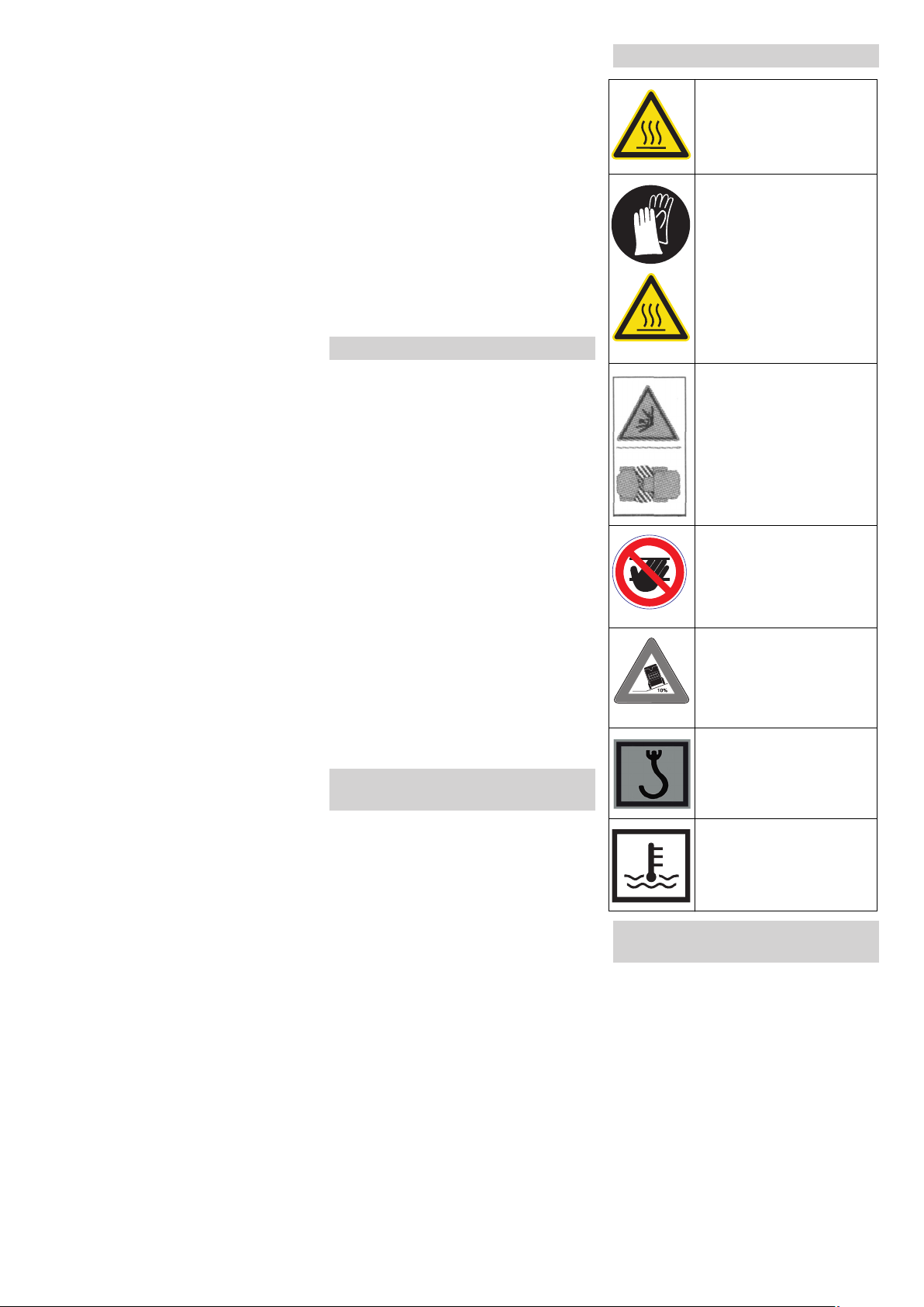
Symbols on the machine
Risk of burns on account of
hot surfaces! Allow the exhaust to cool down sufficiently before starting work
on the machine.
Caution
Risk of burns on account of
hot hydraulic quick couplers! Wear gloves while
separating the couplings.
Danger
Danger of crushing. Make
sure that no persons are
present near the arm hinges.
몇 Warning
Danger of crushing. Keep
hands off the marked location.
Danger
Danger of tipping. Only
drive on terrain with a max.
of 10% incline.
Chain pick-up / crane point
Lashing point
Fill in cooling water here.
The first 100 operating hours (run-in
time)
Please observe the following during the initial 100 operating hours:
– Let the motor warm up sufficiently prior
to driving or loading the machine.
– Drive carefully and avoid overloading.
– Change the motor oil, motor oil filter and
hydraulic oil filter after 50 operating
hours.
4 EN
- 2
Page 5

Overview of the appliance
Exterior view of MIC 45
1 Wheels
2 Articulated steering in centre of vehicle
3 Front hydraulic connection
4 Front attachment frame *
5 Direction-indicator lamp
6 Lights
7 Wiper
8 Work light
9 Outside mirror
10 Beacon lamp
11 Driver's cabin *
12 Driver's seat *
13 Cabin door *
14 Display for hydraulic oil level and tem-
perature
15 Engine cover
16 Side cover
17 Main switch *
18 Rear hydraulic connection
19 Towing hitch
20 Side cover lock
* see detailed descriptions
Front hydraulic connection Rear hydraulic connection
right (in the direction of travel)
1 Hydraulic couplings main PTO
2 Hydraulic couplings (option)
3 Hydraulic couplings (option)
left (in the direction of travel)
4 Hydraulic coupling pressure 1/2" - 30 l/
min (option)
5 Drain coupling (option)
6 Hydraulic coupling return 1/2" - 30 l/min
(option)
Hydraulic coupling return 3/4" - 60 l/min
(option)
7 Hydraulic coupling pressure 3/4" - 60 l/
min (option)
left (in the direction of travel)
1 Hydraulic couplings main PTO
right (in the direction of travel)
2 Main switch
3 Drain coupling (option)
4 Hydraulic coupling pressure 1/2" - 30 l/
min (option)
5 Hydraulic coupling return 1/2" - 30 l/min
(option)
- 3
5EN
Page 6
Console
This machine is available in two different
models. These instructions describe both
of these models:
Version 1: MIC 45 classic
– The working hydraulic is controlled via
levers
– no automatic drive and work pro-
grammes
Version 2: MIC 45 advanced
– with drive position preselector ECAT
– with multi-function lever to control the
work hydraulics
ECAT = Electronic Computer Aided Transmission
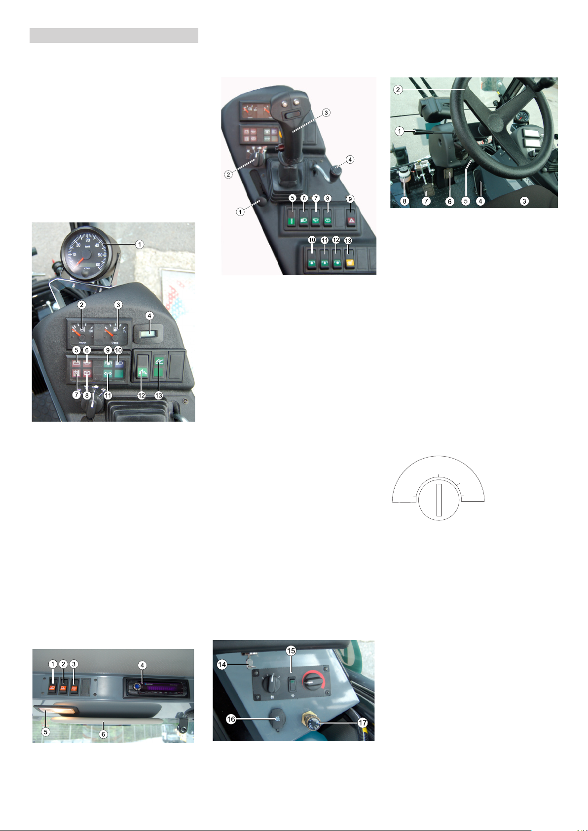
Instruments and indicator lamps
1 Display drive speed
2 Cool water temperature
3 Tank indicator
4 Operating hours meter for motor
5 Warning lamp for battery charging con-
trol
6 Warning lamp oil pressure
7 Warning lamp engine temperature
8 Indicator lamp for parking brakes
9 Indicator lamp work hydraulics ON
10 Indicator lamp for high beams
11 Indicator lamp for directional indicator
12 Speed level 2: up to 40 km/h (for MIC
45 advanced only)
Important instruction: This machine
may only be operated while standing
up!
13 Indicator lamp for float position
Ceiling panel
5 Interior lights
6 Sun visor
Switches on dashboard
1 Setting the motor rpm (hand throttle)
For the MIC 45 classic: for work mode
and drive mode
for the MIC 45 advanced: for work
mode only, drive mode only possible in
rear position
2 Drive position preselector (MIC 45 ad-
vanced only) *
3 Multi-function lever work hydraulics
(MIC 45 advanced only or as an option
for the MIC 45 classic) *
4 Lever for left rear work hydraulics (MIC
45 advanced only or as an option for the
MIC 45 classic) *
5 Cruise control
6 Lights
Front position: For
Central position: Parking light
Rear position: Driving light
7 Wiper
Front position: For
Central position: normal operation
Rear position: fast operation
8 Windscreen washer system
9 Warning system
10 Front work hydraulics - 30 l/min
11 Front work hydraulics - 60 l/min (option)
(actuate together with Pos. 10)
12 Rear right work hydraulics - 30 l/min
(option)
13 Seat heater (option)
17 Turning knob for setting the lowering
speed of the front attachment frame *
* see detailed descriptions
Pedals and steering wheel
1 Blinker lever and horn
(press to sound horn)
2 Steering wheel *
3 Driver's seat *
4 Accelerator pedal *
5 Locking mechanism of emergency
brake
6 Pedal for parking brake
7 Inching pedal/brake pedal *
8 Equalizing reservoir brake fluid
* see detailed descriptions
Driver cabin
* not pictured
1 Driver's door
2 Driver's door release
3 Cabin door
(can only be opened from the inside)
4 Interior door unlock
Ignition
ON
GL
OFF
1 OFF: Ignition off
2 ON: Ignition on
3 GL: Pre-heat
4 ST: Start motor
ST
1 Front work light switch
2 Rear work light switch
3 Switch beacon lamp
4 Radio
14 Ignition key
15 Heating and air conditioning *
16 On board socket 12 V
6 EN
- 4
Page 7
Operations
Setting the motor rpm
MIC 45 classic / MIC 45 advanced
MIC 45 classic
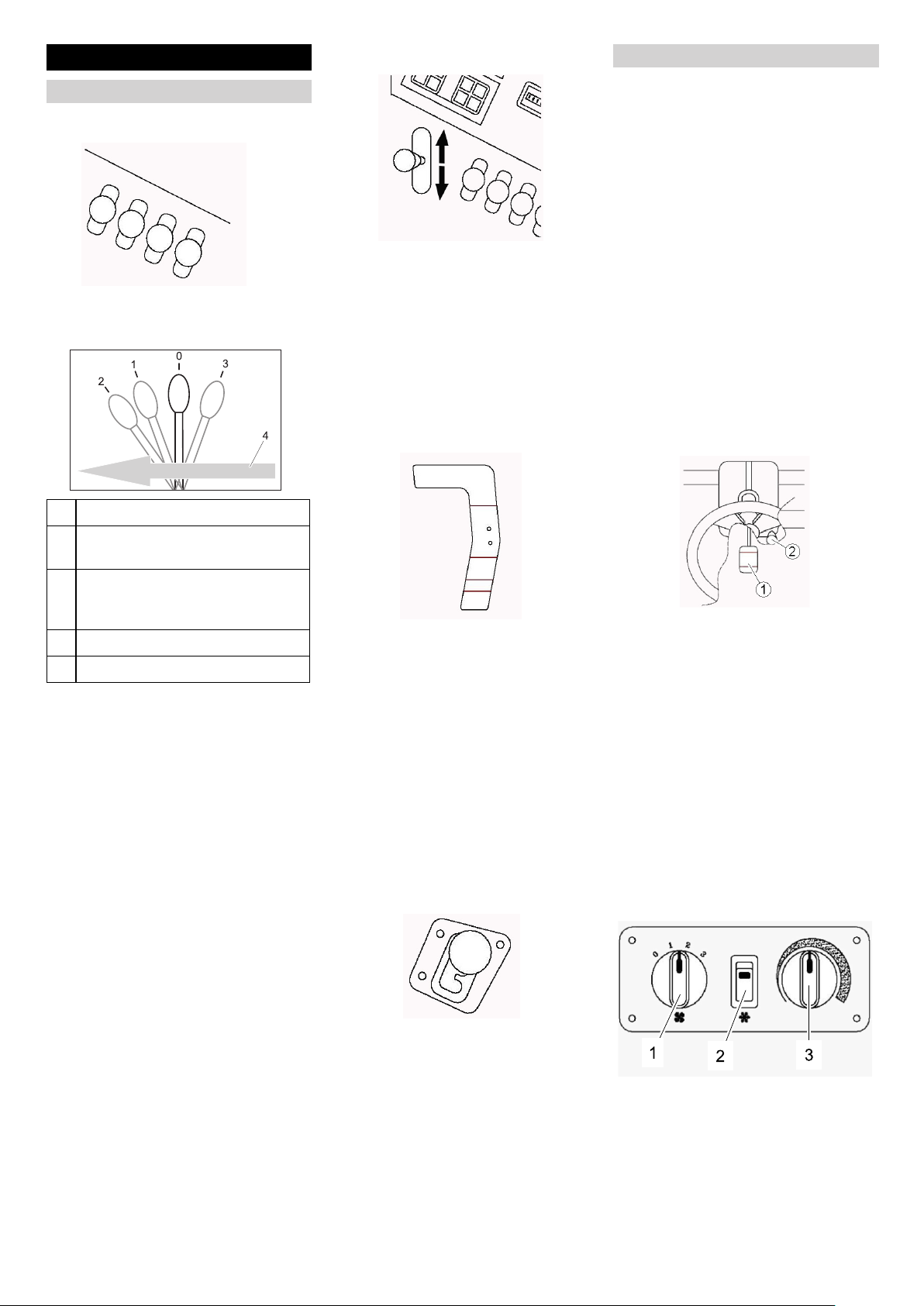
Control lever
Depending on the model, the machine is
equipped with 2 or 4 control levers.
Function:
0 Resting position
Throttle to the rear: Low speed
Throttle all the way to the front: High
speed
Note: To drive and work, position the
throttle all the way in the front (high
speed); the drive speed is controlled via
the accelerator pedal.
Drive pedal
The accelerator pedal determines the driving direction as well as the speed of the machine.
Cruise control
With the cruise control, the accelerator
pedal can be locked in any position at any
speed.
Switching on the cruise control: Use the
accelerator pedal until the desired
speed is reached. Then, press the
cruise control switch on the dashboard.
Release the accelerator pedal, the ma-
chine will maintain the set speed.
Switching off the cruise control: The
cruise control can either be switched off
via the switch or by pressing the inch-
ing/brake pedal.
Inching pedal/brake pedal
The inching pedal regulates the speed in all
work modes. Also functions as a brake.
Use the inching pedal to reduce the
driving or working speed.
Parking brake
1 lower and press down, lever will not
lock in
2 lowered, float position, work appli-
ance follows the floor contour (e.g.
snow removal shield), lever locks in
3 raise, lever will not lock in
4 Forward travel direction
With 2 control levers:
The front attachment frame is raised
and lowered via the left control lever. If
the lever is pushed all the way to the
front, the front attachment frame is in
float position.
Note: This float position is needed
when attachments are guided along the
ground (e.g. snow plow). It is also part
of the safety equipment and must be
switched on for hydraulic operation of
other attachments.
The right control lever is used to raise
and lower the attachment.
With 4 control levers:
The two centre levers (optional) are
used to control the front-mounted attachments.
The right control lever is used to control
rear-mounted attachments.
Press the accelerator pedal to the front:
Machine will move forward.
Press the accelerator pedal to the rear:
Machine will move in reverse.
The harder the accelerator pedal is
pressed, the faster the machine will
move. The final speed is determined by
the position selected with the speed
preselector.
If you release the accelerator pedal, the
machine is braked using all driven
wheels and will come to a stop.
In case of a change of direction (for-
ward/reverse), let the machine come to
a brief stop.
Speed preselector
There are 3 different speed ranges; the machine should be at a standstill while switching between them.
– Top position: High speed range
– Centre position: normal speed range
– Bottom position: low speed range
몇 Danger
Activate the emergency brake prior to leaving the machine.
1 Pedal for parking brake
2 Locking
The emergency brake prevents the machine from rolling away and is a safety feature during the startup at the same time.
Lock the emergency brake:
Press the emergency brake pedal all
the way day and pull on the lock under
the steering wheel.
Release emergency brake:
Push down the emergency brake pedal,
the release will open.
Heating and ventilation
The fresh air is suctioned by a dust filter on
the rear of the cabin.
1 Switch ventilator blower
2 Air conditioning switch (option)
3 Temperature regulator of heater
The circulation louvre is located behind
the seat. To adjust it, loosen the rotary
knob slightly and pull it to the side.
- 5
7EN
Page 8

1 Circulation louvre
2 Rotating knob
Adjustable air nozzles are mounted on
the seat console and on the front edge
of the dashboard.
Rotary knob of lowering speed
The rotary knob for the lowering speed
is used to adjust the lowering speed of
the front attachment frame.
Lever for mechanical lock
1 Multifunctional lever
2 Blinker switch
FORWARD: Press the switch to the left
(green diode lights up)
NEUTRAL/STOP: Switch in centre position (without indicator lamp)
REVERSE: Press the switch to the right
(yellow diode lights up)
3 Yellow diode
4 Green diode
5 Press and hold the yellow switch button
for the second hydraulic function on the
front attachment (e.g. for the V shield's
left/right movement)
6 Switch knob for operation of attach-
ments
7 Drive position preselector
8 Lever for rear work hydraulics
Controlling the front attachment frame
Activate the front lift: The lever for the
mechanical lock must be in the bottom position.
For float position:
Press the multi-function lever all the
way forward and lock it in.
Note: This float position is needed when attachments are guided along the ground
(e.g. snow plow).
Control of hydraulic connection 1
Press the multi-functon lever toward
the side: The front right hydraulic con-
nection 1 will be activated.
For float position:
Multi-function lever all the way to the
left.
Control of hydraulic connection 2 (option)
Press the multi-functon lever toward
the side and press the yellow switch
knob at the same time: The front right
hydraulic connection 2 will be activated.
During transports, the front attachment
frame can be lifted all the way up and
locked; for this, pull the lever all the way
up.
Note: The lever is used to activate the
hydraulic connection 3 on the right front
(option) when it is in the top position.
MIC 45 advanced
Multifunctional lever
The front attachment frame and the front
attachments are controlled via the multifunction lever.
Pull the multi-function lever towards
you: The front attachment frame will
rise.
Press the multi-functon lever toward
the front: The front attachment frame
will lower.
For float position:
Press the key below the yellow knob on
the multi-function lever; the indicator
lamp for the float position will illuminate.
Control of hydraulic connection 3 (option)
Lift the front attachment frame up.
Pull the lever for the mechanical lock all
the way up.
Note: The front lift is deactivated.
Hydraulic connection 3 is activated.
8 EN
- 6
Page 9
For float position:
Press the multi-function lever all the
way forward and lock it in.
Control for rear work hydraulics
The rear left hydraulic connection is ac-
tivated via the lever.
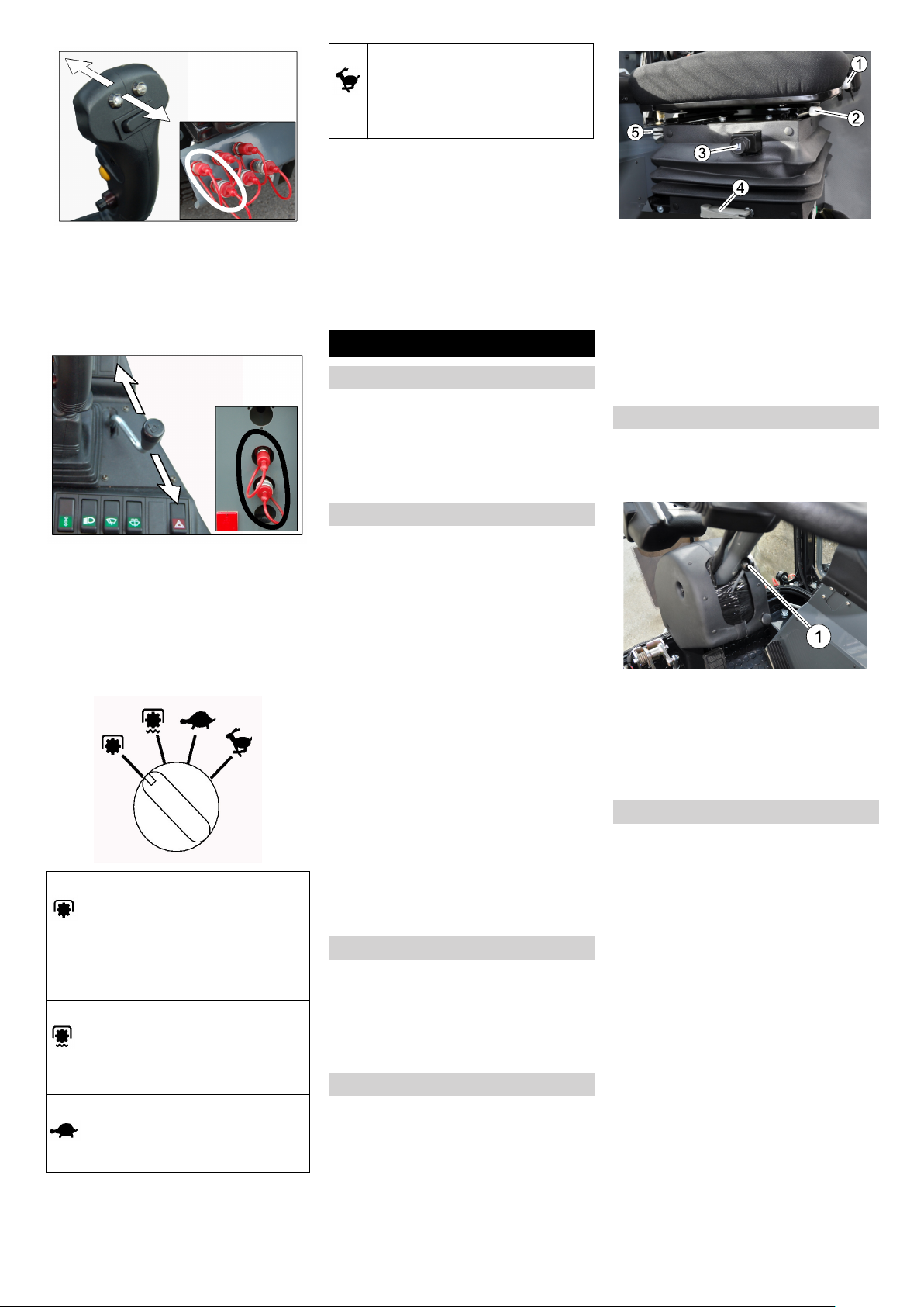
FAST TRANSPORT RANGE:
The drive speed is regulated via
the accelerator pedal. Max. speed
approx. 30 km/h or 40 km/h with
speed level 2.
Drive pedal (foot accelerator)
If the drive pedal is pressed, the motor
speed will increase. The pedal is springloaded; if you remove your foot, the motor
speed will decrease.
몇 Important
During transport drives, use the drive pedal
carefully, because there is a risk of sudden
speed decrease!
Before Startup
Prior to initial start-up
The document pouch is located behind
the driver's seat. Always keep the en-
closed documents in this pouch. This
way, you and possible transport com-
panies will always have access to im-
portant information.
Refuelling
1 Arm rest incline
2 Lever for seat adjustment
3 Spring hardness
4 Height adjustment
5 Damping
The left arm rest can be folded up to get
in and out.
The right arm rest can be adjusted for
incline, height and position, matching
the control of the multi-function lever.
Set the steering wheel position
Danger
Danger of accident. Do not adjust the steering wheel position while driving.
Drive position preselector
You can use the drive position rotary knob
to select the working and driving position.
몇 Important
The driving direction selector switch must
be set to NEUTRAL/STOP before you can
use the drive position rotary knob!
WORK RANGE 1:
For hydraulic attachment. The
max. speed represents the set motor speed.
Important! The speed is then regulated electronically via the drive
pedal.
WORK RANGE 2:
Working position with load sensing. When the load on the attachment fluctuates, the working speed
is regulated electronically.
SLOW TRANSPORT RANGE:
The drive speed is regulated via
the drive pedal. Max. speed approx. 20 km/h.
Danger
Risk of explosion!
– Only use the fuels specified in the Op-
erations Manual.
– Do not refuel the machine in enclosed
spaces.
– Smoking and naked flames are strictly
prohibited.
– Ensure that no fuel reaches the hot
open surfaces.
Switch off engine.
Open fuel filler cap.
Fill in diesel.
Insert the fuelling gun as deep as possi-
ble into the fuel nozzle. Do not add any
more fuel once the fuelling gun stops
according to the settings.
Wipe off any spilt fuel and close fuel fill-
er cap.
Fuelling using a can
Estimate the fuel requirement in order
to avoid overflows.
Windscreen washer system
The reservoir for windshield wiper fluid is
located on the rear right side of the machine.
Check the fluid level daily and refill
commercially sold windshield wiper flu-
id as necessary.
Adjusting driver's seat
Danger
Danger of accident. Do not adjust the driver's seat while driving.
1 Locking
Pull on the lock.
Set the steering wheel to the desired
position.
Slide the lock back and make sure it
locks in.
Prior to start/safety test
Danger
Risk of accidents, injuries. If one point of
the safety check is not fullfilled, the appliance must not be taken into operation, but
must be repaired.
The safety check must be performed before each use of the appliance.
Controls on the right side of the machine
– Check the hydraulic oil level.
– Check engine oil level.
– Check cooler water level.
- 7
9EN
Page 10

Walk around the machine and check for
the following
– Check the hydraulic connections for
cleanliness.
– Check the hydraulic lines for leaks.
– Check the fuel lines and connections for
leaks.
– Check the electrical lines for damage.
– Screws and nuts.
– Check machine, motor and radiator grill
for damages.
– Cleanliness of the filters.
– Tyre pressures, possible tyre wear.
Note: Tyre pressures differ according to
the load on the axles - see Chapter
"Specifications/Tyre Pressure Table"
– Is the main switch switched on?
Check while sitting on the machine
– Check the drive pedal for easy move-
ment.
– Is the emergency brake locked?
– Are the switches for the work hy-
draulics switched off?
Note: The hydraulic lever or multi-func-
tion lever for the front attachment frame
must be in float position.
– With the ignition turned on: Are the
warning lamps for load control and oil
pressure illuminated?
Start the motor and check
– Do the warning lamps for load control
and oil pressure shut off?
– Does operating hour counter and tem-
perature control function?
– Are the lights and the blinking system
functioning?
– Is there sufficient liquid in the reservoir
for the windshield washer?
– Check the neutral position of the drive
pedal: Drive the appliance forward and
backwards. When the drive pedal is released, the machine must stop in every
direction of travel.
– Check the exhaust system for leaks.
– During a short test drive, listen for ab-
normal sounds and check for vibrations.
Operation
Danger
Danger of crushing. Make sure that no persons are present near the arm hinges.
Danger of burns, crushing. Only use the
appliance if all casing parts have been attached.
Caution
Danger of damage due to lack of lubrication.
If the oil pressure warning lamp lights up during operation, switch the engine off immediately and remediate the malfunction.
Risk of damage due to overheated engine
or overheated hydraulic oil. If the warning
lamps for engine temperature or hydraulic
oil temperature lights up, set the engine
speed to idle (do not turn the engine off)
and perform the measures in the Chapter
"Malfunctions".
Start the engine
– Is the main switch switched on?
– Is the emergency brake locked?
– Are the switches for the work hy-
draulics switched off?
Sit on the driver's seat.
Insert the ignition key into the ignition
lock.
(For normal transmissions) keep
your foot off the accelerator pedal.
(For ECAT) driving direction selector
switch on the multi-function lever to
centre position NEUTRAL/STOP.
Set the throttle to half throttle.
Turn the ignition key to position "I".
Note: The warning lamps of the load
control and the oil pressure must be il-
luminated.
With low exterior temperatures, turn the
ignition key to pre-heating setting for
about 3 seconds.
Turn the ignition key to "Start engine"
and hold it there until the engine starts
up.
Release the ignition key. The ignition
key turns to position "1", engine on.
Note: The warning lamps for the load
control and the oil pressure must turn
off; if this is not the case, shut the motor
off and troubleshoot the fault.
Let the motor warm up in half-throttle
position for a while.
Driving
몇 Important
Do not load the motor excessively before it
is warmed up.
During transport drives, use the drive pedal
carefully, because there is a risk of sudden
speed decrease!
During transports, the front attachment
frame can be lifted all the way up and
locked; for this, pull the lever all the way up.
Release parking brake.
Set the throttle to max. engine speed.
(For normal transmissions) select the
desired setting (3 settings) on the
speed preselector.
Note: This speed preselection must
only take place while the machine is
standing still.
Forward drive: Slowly press the accel-
erator pedal to the front.
Driving in reverse: Slowly press the ac-
celerator pedal to the rear.
(For ECAT) Rotate the drive position
rotary knob to the desired working or
transport position.
Important instruction: Switching to
the speed level 2 (40 km/h) must not
take place during the drive, but only
while the machine is standing still.
Set the driving direction selector switch
on the multi-function lever to forward or
reverse.
Slowly press the accelerator pedal to
the front.
Control the driving direction with the
steering wheel.
Driving over obstacles
Hurdles up to 20 cm in height:
Bypass the hurdle slowly and carefully
at an angle of 45°.
Hurdles more than 20 cm in height:
Only drive over these obstacles using a
suitable ramp.
몇 Warning
Risk of damage! Ensure that the vehicle
does not get stuck up.
Shutting down the appliance
Release the accelerator pedal, the ma-
chine brakes automatically and stops.
Only use the brake pedal if the appli-
ance does not stop even though the accelerator pedal has been released.
Set the throttle to idle.
Lower the attachment to the floor.
Switch off the attachment hydraulics.
Activate parking brake.
Turn the ignition key to OFF position.
Motor off" and remove the ignition key.
Switch off at main switch.
Attachments
Different attachments (not included in the
scope of delivery) can be connected to the
front or the back of this machine. Attachments that may jeopardise the safety or
stability of the machine, must not be used.
IMPORTANT! Before connecting attachments that were not specifically intended
for this machine, please contact your dealer; he will check how and if these attachments should be connected and used. This
is essential for the safety of the driver and
the machine as well as for possible warranty claims.
몇 Important
Please read the operating instructions for
the attachment you intend to use before
connecting it!
Drive the machine toward the attach-
ment. Lower the machine frame far
enough to fit into the machine holder.
Lift the attachment frame high enough
to be able to connect the two machine
plugs.
Shut the motor off and connect the hy-
draulic hoses of the attachments to the
hydraulic couplings of the machine.
Start the motor und check whether the
hydraulic drives of the attachments are
working properly.
10 EN
- 8
Page 11

Towing hitch
The permissible drawbar and drawing
loads of the tractor are indicated in the
Chapter "Technical Specifications".
Storage
몇 Warning
Risk of injury and damage! Note the weight
of the appliance in case of storage.
If the appliance is going to be out of service
for a longer time period, observe the following points:
Park the appliance in a safe, level and
dry place.
Turn ignition key to "STOP" and remove
it.
Switch off at main switch.
Secure appliance to prevent it rolling
away, lock emergency brake.
Change the engine oil and the oil filter
prior to extended storage.
If frost is expected, check whether there
is enough anti-frosting agent in the
cooling water.
Clean the inside and outside of the ma-
chine.
Charge battery approx. every 2 months.
Maintenance and care
Maintenance schedule
Note
The elapsed-time counter shows the timing
of the maintenance intervals.
Daily before starting operations
See chapter "Prior to start/safety test".
After the first 50 operating hours
Have the initial inspection performed by
Customer Service.
– Change the engine oil and the oil filter.
– Replace hydraulic oil.
– Check cooler water level.
– Check the V-belt and V-belt tension.
Every 100 operating hours
– Change engine oil.
– Lubricate the joints, machine holders
and cylinders (list of grease fittings, see
chapter "Lubricating machine").
– Oil the ropes and joints.
– Check cooler water level.
– Check the hydraulic oil level.
– Check battery.
– Check whether all screw joints are tight;
tighten them, if necessary.
– Check the V-belt and V-belt tension.
– Check drum brake for function and set-
ting.
– Check the hydraulic couplings for leaks.
– Clean air filter.
– Clean the radiator grill.
Every 200 operating hours
– Change the motor oil filter.
Every 300 operating hours
– Replace hydraulic oil filter.
– Replace the ventilation filter on the hy-
draulic oil tank.
Every 600 operating hours
– Replace hydraulic oil.
– Replace the cooling liquid with frost pro-
tection.
– Replace the fuel filter.
Every 800 operating hours
– Check the valve gap and adjust it (done
by customer service).
– Check the injector nozzles and clean
them (by Customer Service).
After each vehicle wash
Grease the joint connection.
Maintenance Works
몇 Important
In order to avoid operational problems, utmost cleanliness is vital for all check and
maintenance work.
Park the machine on an even surface.
Activate parking brake.
Allow the machine sufficient time to cool
down before carrying out any mainte-
nance and repair work.
Do not touch any hot parts, such as the
drive motor and exhaust system.
Cooling water is hot.
Lower the attachments to the ground or
secure them in the raised position.
Secure the raised machine.
General notes on safety
Danger
Risk of injury due to engine overrun. Once
the engine has been switched off, wait for 5
seconds. Stay well clear of the working
area for this time.
When cleaning the appliance with a high
pressure cleaner, adhere to the respective
safety instructions.
Risk of injury if the machine is left running
in an unattended state. Remove the key
and disconnect the battery before working
on the appliance.
Do not point the high pressure jet towards
electrical components, tyres, radiator fins
and hydraulic hoses.
Maintenance on the hydraulic system must
only be carried out by trained personnel.
Never disassemble hydraulic hoses while
the machine is running.
Please do not release engine
oil, fuel oil, diesel and petrol
into the environment. Protect
the ground and dispose of
used oil in an environmentallyclean manner.
Safety notes regarding the batteries
Please observe the following warning notes
when handling batteries:
Observe the directions on the
battery, in the instructions for
use and in the vehicle operating instructions!
Wear an eye shield!
Keep away children from acid
and batteries!
Risk of explosion!
Fire, sparks, open light, and
smoking not allowed!
Danger of causticization!
First aid!
Warning note!
Disposal!
Do not throw the battery in the
dustbin!
Danger
Follow accident prevention regulations as
well as DIN VDE 0510, VDE 0105 T.1.
Risk of explosion! Do not put tools or similar
on the battery, i.e. on the terminal poles
and cell connectors.
Risk of injury! Ensure that wounds never
come into contact with lead. Always clean
your hands after having worked with batteries.
Risk of fire and explosion!
– Smoking and naked flames are strictly
prohibited.
– Rooms where batteries are charged
must have good ventilation because
highly explosive gas is emitted during
charging.
Danger of causticization!
– Rinse thoroughly with lots of clear water
if acid gets into the eye or comes in contact with the skin.
– Then consult a doctor immediately.
– Wash off the acid If it comes in contact
with the clothes.
- 9
11EN
Page 12

Installing and connecting the battery
Insert battery in battery mount.
Connect pole terminal (red cable) to
positive pole (+).
Connect pole terminal to negative pole
(-).
Screw the battery and its holder to the
floor.
Note
Before removing the battery, make sure
that the negative pole lead is disconnected.
Check that the battery pole and pole terminals are adequately protected with pole
grease.
Charging battery
Danger
Risk of injury! Comply with safety regulations on the handling of batteries. Observe
the directions provided by the manufacturer
of the charger.
Danger
Charge the battery only with an appropriate
charger.
Loosen the wheel nuts/wheel bolts by
about 1 revolution using a suitable tool.
Raise machine using vehicle jack.
Unscrew the wheel nuts/wheel bolts
and remove them.
Remove wheel.
Have the defective wheel repaired by a
specialised repair shop.
Place the wheel and screw in the wheel
nuts/wheel bolts all the way; tighten
them lightly.
Lower machine using vehicle jack.
Torque the wheel nuts/wheel bolts to
the required torque.
MIC 45 advanced 180 Nm
MIC 45 classic 300 Nm
Remove/attach engine panels
To complete the different maintenance
tasks, the side panels must be removed.
Grasp the top panel by the rear end and
pivot it up against the resistance.
몇 Warning
Risk of burns Let the appliance cool off before removing the panels.
Remove the engine's side panels
Check engine oil level and top up, if required
1 Oil dipstick
2 Oil fill cover (motor)
Pull out oil dipstick.
Wipe off oil dipstick and insert.
Pull out oil dipstick.
Unscrew all cell caps.
Connect positive terminal cable from
the charger to the positive pole connection on the battery.
Connect negative terminal cable from
the charger to the negative pole connection on the battery.
Plug in mains connector and switch on
charger.
Charge battery using lowest possible
level of charging current.
Note: When the battery is charged, first remove the charger from the mains and then
disconnect it from the battery.
Replacing wheel
Danger
When carrying out repairs on public highways, wear warning clothing when working
close to passing traffic.
Danger
Risk of injury!
Park the machine on an even surface.
Activate parking brake.
Remove ignition key.
Check stability of ground. Also secure
the machine with wheel chock(s) to prevent it rolling away.
Position vehicle jack at the appropriate
mounting point for the front or rear
wheel.
Note
Use a suitable commercially available vehicle jack.
1 Right side panel lock
2 Left side panel lock
Open both locks.
Lift the panel up toward the top and re-
move it to the side.
Install the engine's side panels
Insert the panels from the side.
Hook the panel into the mounting
groove on the upper edge.
Slide the panel into the desired position
and secure with the locks.
Read the value of the oil level.
Insert the oil dip again.
– The oil level must lie between “MIN“
and “MAX“ marking.
– Add motor oil if the oil level is below the
"MIN" marking.
– Do not fill oil above the "MAX" marking.
Unscrew the oil fill lid.
Fill in motor oil.
For oil type refer to Chapter "Technical
specifications".
Close the oil fill lid.
Wait at least 5 minutes.
Check engine oil level.
Caution
An oil level that is too high leads to damages of the engine by overheating. If the oil
level exceeds the "MAX" mark, oil must be
drained until the correct oil fill level has
been reached.
Change the motor oil and the oil filter
Every 100 operating hours: Replace the
engine oil.
Every 200 operating hours: Change the
motor oil filter.
Note: A warm motor facilitates the draining
process.
Danger
Risk of burns due to hot oil or possible hot
hose lines!
Ready a catch bin for appr. 6 litre oil.
Unscrew oil drain plug.
Unscrew the oil fill lid.
Drain off oil.
Unscrew the oil filter.
Clean the intake and sealing areas.
12 EN
- 10
Page 13

Coat the washer of the new oil filter with
oil before fitting it.
Fit in the new oil filter and tighten it by
hand (torque to 45 - 53 Nm).
Screw in the oil drain screw along with
the new washer (torque to 33 - 37 Nm).
Fill in motor oil.
For oil type and filling quantity refer to
Chapter "Technical specifications".
Close oil filler opening.
Let the motor run for approx. 30 sec-
onds.
Check engine oil level.
Check hydraulic oil level and refill hydraulic oil
Every 100 operating hours
몇 Important
In order to avoid operational problems, utmost cleanliness is vital for all check and
maintenance work.
The oil level is checked at the sight gauge,
the level should be at least up to the middle
of the sight gauge.
1 Hydraulic oil tank
2 Filter casing with fill opening
3 Sight gauge for oil level and oil temper-
ature
4 MIN oil level
5 Hydraulic fluid
6 MAX oil level
Top up hydraulic oil in the filter casing if
necessary.
Clean the lid and the surroundings.
Open the screw connection on the filter
casing.
Refill hydraulic oil.
Important: Use a tight-meshed sieve
for refilling, because even fine grain dirt
can damage the hydraulic pumps.
For oil type refer to Chapter "Technical
specifications".
Replace the hydraulic oil filter in the hydraulic oil tank.
Every 300 operating hours
Even the finest contamination in the hydraulic system can cause severe faults;
therefore, the system is fitted with a hydraulic oil filter.
Note: Replace the ventilation filter when
you replace the hydraulic oil filter.
Replacement must be performed by the authorised customer service.
Replace hydraulic oil
Every 600 operating hours
Replacement must be performed by the authorised customer service.
Check hydraulic unit
Check all hydraulic hoses and connec-
tions and ensure that they are leakproof.
Only the authorised customer service is
permitted to carry out maintenance tasks
on the hydraulic unit.
Check cooling water units
Check coolant level daily.
Every 600 operating hours: Replace the
cooling liquid.
– The cooling water level must be
checked while the engine is cooled off.
– The cooling water level must be at the
lower marking.
1 Cooling water equalising reservoir
Remove the right engine panel.
Refill cooling water
– Use a water and antifreeze mixture to
refill.
– Do not mix different antifreeze types.
– Use only soft water for the water and
antifreeze mixture.
– Refill cooling water only while the en-
gine is cool.
Remove the right engine panel.
If the cooling water reservoir is completely
empty, first fill up the radiator:
Unscrew the radiator lid.
Fill the radiator slowly all the way to the
top without bubbles.
Screw on the radiator lid.
Fill the cooling water equalising reservoir:
Remove the lid of the equalising reser-
voir.
Fill the equalising reservoir to the bot-
tom mark.
Close the lid for the equalising reser-
voir.
Start the engine and let it warm up.
Check fill level in the cooling water ex-
pansion reservoir.
While the engine is warm, the cooling
water level must be at the top mark.
If the cooling water level is too low, shut
the engine off, let it cool off and fill the
missing cooling water volume into the
cooling water equalising reservoir.
Replace the fuel filter.
Every 600 operating hours
Danger
Risk of explosion!
– Do not carry out maintenance tasks in
closed rooms.
– Smoking and naked flames are strictly
prohibited.
1 Fuel filter
Place the collection trough under the
fuel filter.
Remove the fuel filter.
Moisten the gasket of the new filter with
diesel fuel and tighten the filter manually.
Deaerate the fuel system
Deaerating the fuel system
If the tank is empty or if the fuel filter was replaced, the fuel system must be ventilated.
1 Deaeration screw
Check if the fuel tank is filled.
Open the ventilation screw on the injec-
tion pump.
Activate starter motor for about 10 sec-
onds.
Close the ventilation screw and start the
engine.
If the engine does not start, repeat the
ventilation process.
- 11
13EN
Page 14

Cleaning and replacing the fuel filter
Clean every 100 operating hours: for
heavy contamination clean before then.
1 Air filter housing
2 Wing nut
Unscrew wing nut.
Remove the cover and the filter insert.
Clean the interior of the air filter reser-
voir.
Clean the filter insert: Knock the dust off
on a hard surface, do not blow out with
compressed air.
Check that the sealing surface and the
filter insert are clean and undamaged.
Insert the cleaned filter insert.
Important: A severely contaminated or
damaged filter insert must be replaced.
Lubricate the machine
Caution
Risk of functional disturbances. Do not let
the V-belts get in contact with the grease.
The machine is equipped with the following
grease fittings:
1 Articulated steering in centre of vehicle
2 Machine frame
3 Lifting cylinder
4 Steering cylinder
5 Accelerator pedal (MIC 45 classic only)
Use high quality multi-purpose grease
and use grease gun to lubricate.
The remaining joints and sheathed ca-
bles must be lubricated with motor oil.
Checking the V-Belt
Check the tension and the condition of the
V-belt regularly.
If the tension is correct, the V-belt can
be deflected by about 7 mm.
Get the V-belt tension adjusted by an
authorized customer service.
Check battery
Caution
The safety instructions regarding batteries
must be observed - see first part of these
instructions.
Check the acid level of the battery reg-
ularly. Refill distilled water as needed
(up to approx. 10 mm above the cells).
The cable shoes must be tightened and
free of oxidation. Grease with acid-free
grease.
Adjustment tasks
Safety-relevant functions on the machine
such as the neutral position of the acclerator pedal and the readjustment of the emergency brake are adjustable. These tasks
must only be performed by the authorised
customer service.
Cleaning tasks
Cleaning the device
Clean appliance daily after finishing work.
Caution
Risk of damage!
Shaft seals, electrical components and hydraulic valves must not be cleaned using a
high pressure water jet.
Do not rinse the engine with water.
Radiator fins must only be cleaned with
compressed air (max. 5 bar), not with water.
Do not use aggressive cleaning agents.
In order to protect the air filter only wash the
rear of the appliance while the motor is shut
off.
Check for oil and fuel leaks to prevent
fires. Get customer service to fix the
leaks.
To avoid fires, keep the engine, muffler,
battery and fuel tank free of plant resi-
due and oil.
Check the engine for contamination,
clean with a brush or compressed air if
required
Clean the hydraulic oil cooler and the radiator
The hydraulic oil cooler is located to the left
of the radiator (in the direction of travel).
A dirty radiator will easily cause over-
heating: Always keep the radiator grill,
suction grill and the blower free of dam-
age, grass clippings, dust, etc.
Replacement tasks
Fuses
Both fuse boxes are located behind an access door on the right side of the cabin.
Check the fuses.
Replace defective fuses.
Note: Only use fuses with identical
safety ratings.
14 EN
- 12
Page 15

Troubleshooting
Faults with display
Display Cause Remedy By whom
Warning lamp for
motor temperature
lights up
Warning lamp for
hydraulic oil temperature
Warning lamp for
battery lights up
Engine is overheated Set the engine speed to idle.
Hydraulic oil overheated
Battery is not being charged Call Customer Service. Operator
Faults without display
Fault Remedy
Appliance cannot be started Turn on the main switch.
Charging or replacing battery
Fill in fuel, deaerate the fuel system
Clean or replace fuel filter
Clean the radiator (see "Care and Maintenance).
Run the engine in idle until the warning lamp turns
off.
Check the level of cooling liquid in the engine.
If the warning lamp does not turn off within 5 minutes, shut off the engine and contact Customer
Service.
Operator
Check fuel pipes, connections and joints and maintain them if required
Contact the authorised customer service.
Engine is running erratically Clean or replace air filter
Check fuel pipes, connections and joints and maintain them if required
Contact the authorised customer service.
Engine is running but machine is
only moving slowly or is not moving at all
Operation problems with hydraulic movement parts
Release parking brake
Pull the hand throttle lever all the way to the rear (MIC 45 advanced only)
Check level of hydraulic fuel
Contact the authorised customer service.
Contact the authorised customer service.
Towing
Caution
Risk of damage. The machine may not be
towed. Do not move the machine at a
speed higher than walking speed.
Danger
The appliance is not approved for crane
loading.
Fasten the towing rope to the towing
eye in the front or the rear.
Slowly drag the appliance onto the
transport vehicle.
Caution
Risk of damage to the gear. Only push or
pull the appliance slowly.
- 13
15EN
Page 16

Specifications
MIC 45 classic MIC 45 advanced
Driving speed km/h 30 40
Working speed km/h max. 30 max. 30
Climbing capability (max.) % 25 25
Driven axles 44
Engine
Type -- Kubota V1505-T-EU1
Type -- 4-cylinder 4-stroke diesel engine
Cooling type -- Water cooling
Cylinder capacity cm
Holes mm 78
Hub mm 78,4
Engine output at 3000 rpm kW/HP 33/45
Electrical system
Battery V, Ah 12, 44
Oil grades
3
1498
Engine oil type SAE 10W-30
Engine oil volume l 6,7
Hydraulic oil as per DIN 51524, part 3 HV 46
Hydraulic oil volume l 25
Tyres
Super Turf
Size -- 26x12.00-12 8PR
26x12.00-12 4PR
Tyre pressure MPa (bar) 0,14 - max. 0,27 (1,4 - max 2,7)
Max. axle load MPa (bar) 0,27 (2,7)
Machine without load MPa (bar) 0,14 (1,4)
Tyres
Winter
Size -- 195/70 R15 T95
Tyre pressure MPa (bar) 0,2 (2,0)
Greases
For points to be lubricated manually -- Multi-purpose grease
Working conditions
Temperature °C max. + 40
Dimensions and weights
Length x width x height mm 2631 x 1300 x 1947
Unladen weight kg 1410 1400
Permissible overall weight kg 2200 2500
Front axle load kg 725 740
Rear axle load kg 685 660
Max. permitted axle load, front kg 1500 1600
Max. permitted axle load, rear kg 1500 1600
Drawbar load of lorry hitch (Option) kg 250 ---
Drawing load of trailer hitch (option), braked kg 1500 2150
16 EN
- 14
Page 17

Drawing load of trailer hitch (option), unbraked 500 750
Permissible total drawing weight, braked kg 3000 4300
Permissible total drawing weight, unbraked kg 2200 4300
Turning radius mm 2020
Capacity of fuel tank, diesel l 43
Warranty
The warranty terms published by our competent sales company are applicable in
each country. We will repair potential failures of your accessory within the warranty
period free of charge, provided that such
failure is caused by faulty material or defects in fabrication. In the event of a warranty claim please contact your dealer or the
nearest authorized Customer Service center. Please submit the proof of purchase.
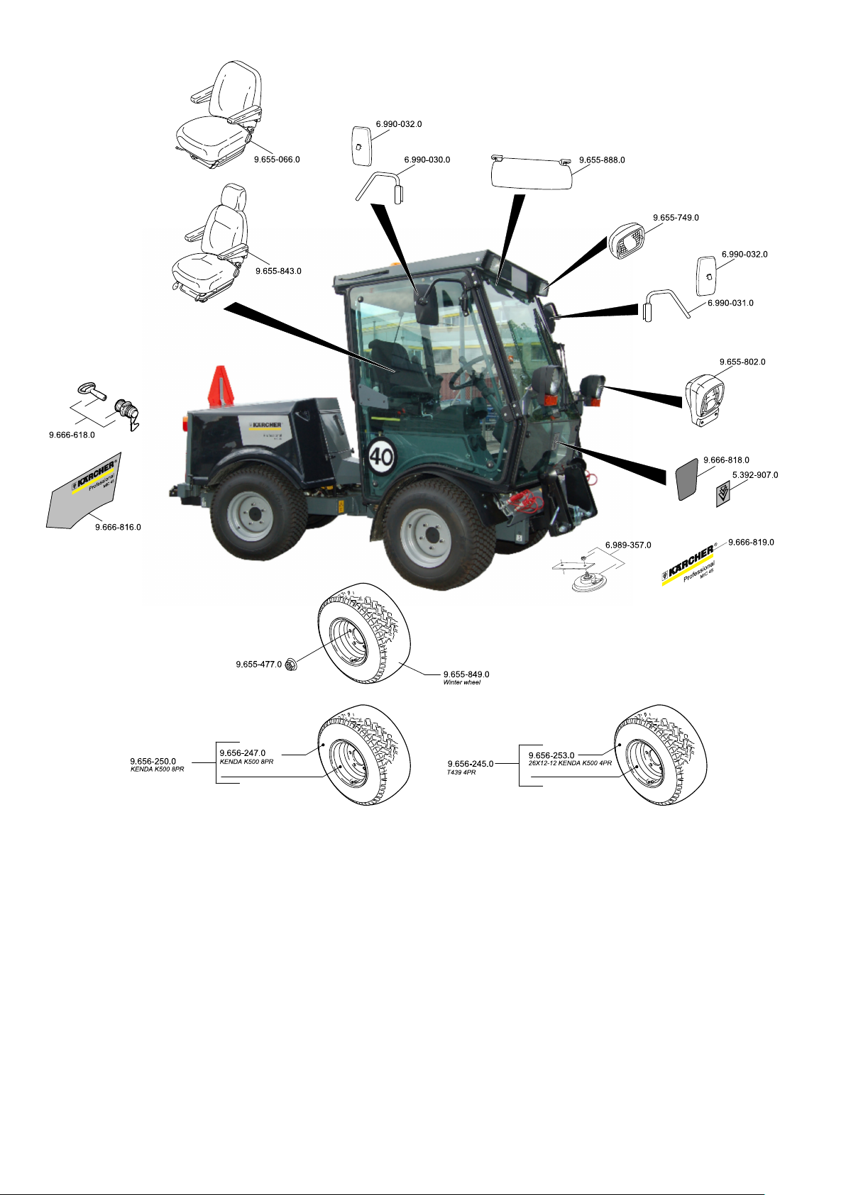
Spare parts
– Only use accessories and spare parts
which have been approved by the manufacturer. The exclusive use of original
accessories and original spare parts
ensures that the appliance can be operated safely and trouble free.
– At the end of the operating instructions
you will find a selected list of spare
parts that are often required.
– For additional information about spare
parts, please go to the Service section
at www.kaercher.com.
- 15
17EN
Page 18
Page 19

http://www.kaercher.com/dealersearch
Alfred Kärcher GmbH & Co. KG
Alfred-Kärcher-Str. 28 - 40
71364 Winnenden (Germany)
Tel.: +49 7195 14-0
Fax: +49 7195 14-2212
 Loading...