

Page 1
Printed in Korea
Part No. PT36-041-011
jWIN®
General Mobile Radio Service (GMRS)
Model: JG-MRS42
Owner’s Manual
Page 2

FCC Warnings
Warning: Adjustment to this unit or replacement of any transmitter
component (crystal, semiconductor, etc.) to this unit could result in a
violation of the rules.
NOTE: This equipment has been tested and found to comply with the
limits for a Class B digital device, pursuant to Part 15 of the FCC Rules.
These limits are designed to provide reasonable protection against
harmful interference in a residential installation. This equipment
generates, uses and can radiate radio frequency energy and, if not
installed and used in accordance with the instructions, may cause
harmful interference to radio communications.
However, there is no guarantee that interference will not occur in a
particular installation. If this equipment does cause harmful interference
to radio or television reception, which can be determined by turning the
equipment off and on, the user is encouraged to try to correct the
interference by one or more of the following measures:
1. Reorient or relocate the receiving antenna.
2. Increase the separation between the equipment and receiver.
3. Connect the equipment into an outlet on a circuit different from
that to which the receiver is needed.
4. Consult the dealer or an experienced radio/TV technician for
help.
.
GMRS LICENSE:
Use of this radio within the United States requires an FCC GMRS
license. An individual 18 years of age or older, who is not a
representative of a foreign government, is eligible to apply for a GMRS
system license. You will need two forms from the FCC; FCC FORM 159
and FCC FORM 605 MAIN FROM and SCHEDULE F. You can find the
forms on line at: http://www.fcc.gov/formpage.html, or call 1-800-418-
3676.
Table Of Contents
FCC WARNINGS ........................................................................................................2
INTRODUCTION.......................................................................................................3
CONTROLS DIAGRAM...........................................................................................3
OPERATION ................................................................................................................ 4
BATTERY INSTALLATION...........................................................................................4
BELT CLIP INSTALLATION..........................................................................................5
TURN THE RADIO ON..................................................................................................5
ADJUST VOLUME.........................................................................................................5
SET THE CHANNEL......................................................................................................5
RECEIVING A CALL.....................................................................................................5
TRANSMITTING A CALL .............................................................................................5
TRANSMITTING A CALL TONE ..................................................................................6
EMG (EMERGENCY)..................................................................................................6
ILLUMINATING THE DISPLAY....................................................................................6
LCD ICONS..................................................................................................................6
SPECIAL FEATURES ...............................................................................................6
AUTOMATIC SQUELCH...............................................................................................6
MONITOR.....................................................................................................................7
KEYPAD LOCK ............................................................................................................7
SCAN.............................................................................................................................7
AUTOMATIC POWER SAVER......................................................................................7
EXTERNAL S PEAKER/MICROPHONE/CHARGER JACK............................................7
MENU – OPTION SETTINGS CHART ...........................................................................8
FREQUENCY TABLE....................................................................................................8
TROUBLE SHOOTING............................................................................................9
OPTIONAL ACCESSORIES...........ERROR! BOOKMARK NOT DEFINED.
CUSTOMER SUPPORT...........................................................................................9
COLUMBIA TELECOMMUNICATIONS LIMITED WARR ANTY
...................................................................ERROR! BOOKMARK NOT DEFINED.
Page 3
Introduction
Included in your package
When you unpack your GMRS radios, you should find the following
items enclosed in the package.
• GMRS1 radio
• Belt clip (attached)
• This manual
Please check for these items carefully. If any items are missing, please
call jWIN Electronics Corp Customer support at 1-866-807-JWIN
between 9am and 5pm EST (Eastern Standard Time).
jWIN GMRS radio has following features.
l Two-way radio with up to a 5 mile range
l 15 channels
l 38 CTCSS
l Built-in VOX (Voice Activated Operation)
l Full Scan
l RSSI (Receiving Signal Strength Indicator)
l Hi/Low power control
l Selectable Call tones (5 tones)
l Selectable key stroke tones
l Time out Timer
l Automatic power saver
l Roger beep confirmation
l Short-cut to Emergency channel
l Rotary volume control (integrated with power on/off)
l Large Back-lit LCD
l Speaker/Microphone/Charger jack
l Both Alkaline and Rechargeable operable
l Splash proof
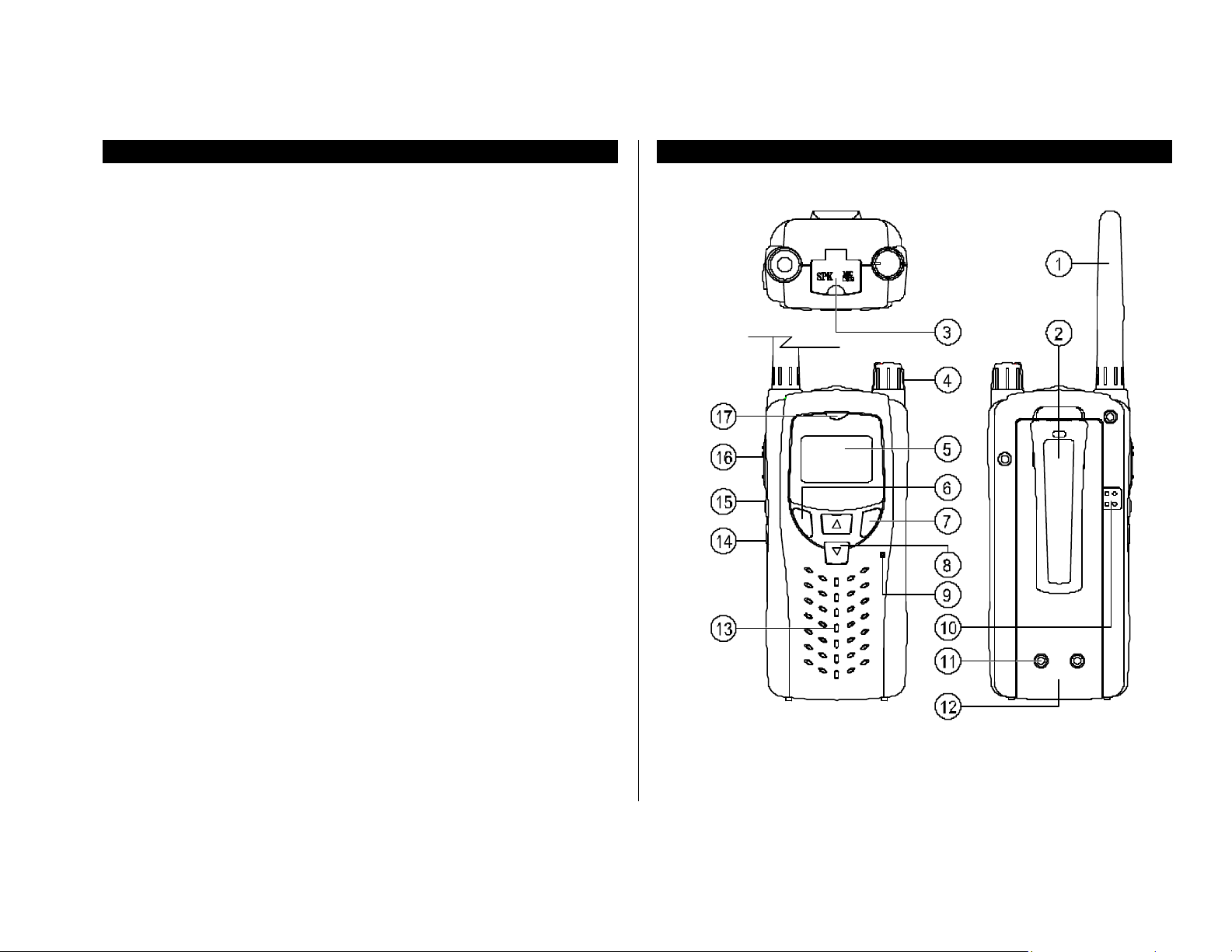
Controls diagram
Page 4

(1) Antenna
(2) Belt clip
(3) Speaker/Microphone/Charger jack
(4) Power/Volume knob
(5) Backlit LCD
(6) Menu/Scan
(7) Call/EMG (Emergency)
(8) Scroll key
(9) Microphone
(10) Battery cover latch
(11) Charging pads
(12) Battery cover
(13) Speaker
(14) Power Hi/Low
(15) Monitor/Lamp
(16) Push-to-talk
(17) Transmission/Reception (TX/RX) LED
Operation
Battery installation
1. Remove the battery cover by pressing release button and
sliding it down from the unit.
2. Install four “AA” (DC 1.5V) alkaline batteries (not included), or
high-capacity rechargeable battery pack (Ni-MH) following the
polarities as engraved inside the battery compartment.
3. Replace the battery cover till it clicks.
Notes:
• Please, do not connect with “wall charger”, when you don’t
insert rechargeable battery in this GMRS1. It may get damage.
• The GMRS has a built-in power saver for maximum battery life.
But when the GMRS is not being used, to conserve battery
power, turn the radio off by turning power knob counterclockwise till it tick s.
• Remove the batteries if the unit will not be used for a long
period of time.
This device complies with Part 15 of the FCC rules,
Operation is subject to the following two conditions:
(1) this device may not cause harmful interference, and
(2) this device must accept any interference received, including
interference that may cause undesired operation.
Figure 1: Installing battery (pack)
Page 5

Belt clip installation
• Removing the belt clip
1. Remove battery cover as shown on Figure 2.
2. Pull the belt clip latch away from the battery cover.
3. Slide up the belt clip while pulling the belt clip latch.
4. Replace battery cover till it clicks.
• Installing the belt clip
1. Remove the battery cover as shown on Figure 2.
2. Slide the belt clip into the till it clicks.
3. Replace the battery cover till it clicks.
2. Turn the power/volume knob counter-clockwise until the radio
clicks to turn the radio off.
Adjust volume
1. Press and hold monitor button, and rotate power/volume knob
till reaching desirable volume level.
2. Release monitor button.
Set the channel
1. The GMRS radio has 15 channels and 38 CTCSS channels.
2. Press scroll up/down key to set the channel you wish to
communicate.
3. Refer to Menu/Scan section if you would like to set CTCSS
channel.
4. Default setting is channel 1 and CTCSS 0.
Receiving a Call
1. The radio is continuously in receiving mode when powered on.
2. Incoming signal can be heard only when both (transmitter &
receiver) radios are on the same channel & CTCSS.
3. The RX LED will light up in amber when incoming signal is
encoded with CTCSS. Otherwise the RX LED will light up in
green.
Figure 2: Removing belt clip
Turn the radio on
1. Turn the power/volume knob clockwise. The radio will beep
and the LCD displays ready saved channel settings.
Transmitting a Call
1. Press and hold the push-to-talk button, and speak gently into
the microphone about 3 inches away from the radio.
2. The TX LED will light up in red.
3. Release the push-to-talk button when finished transmission.
Page 6

Transmitting a Call Tone
1. Press and hold Call/EMG button till the TX LED lights up in red,
and the LCD displays CALL. Then release Call/EMG button.
2. This GMRS radio has 5 different Call Tones. Please refer to
Menu chapter to set different Call Tone.
EMG (Emergency)
1. Press and release Call/EMG button when you are in an
emergency situation.
2. You may speak into the radio, or transmit an emergency Call
Tone for instant HELP.
3. Press and release the Call/EMG button again to exit.
Note: The maximum transmission range will vary depending on terrain
and environment. Range will be greater in open fields, while the range
is shorter within/around buildings or large structures.
override other transceivers of same channel. Please
keep it Lo (Low) at channel 1 through 7.
(8) Emergency channel indicator
Illuminating the Display
1. Press Lamp button to illuminate the LCD when in the darkness.
2. The LCD is illuminated for 5 seconds unless Lamp button is
pressed again.
LCD icons
(1) Active Channel number
(2) Active CTCSS channel number
(3) RSSI (Receiving signal strength indicator)
(4) Automatic Power saver indicator
(5) Roger beep indicator
(6) Scanning indicator
(7) Transmitter power indicator: Keep transmitter power Hi
(High) if receiving party is far beyond 2 miles. Unless
otherwise keep it Lo (Low) all the way, or your radio may
Figure 3: LCD display & icons
(9) VOX (Voice activated transmission)
(10) Battery status indicator
(11) Keypad lock indicator
(12) Keystroke tone indicator
(13) Receiving indicator
(14) Transmission indicator
Special Features
Automatic Squelch
Your GMRS is equipped with automatic squelch circuitry, which filters
out weak transmission and unwanted noise. These signals may be
picked up as background static, and are usually caused by terrain
conditions, or if you have reached the limit of your range.
Page 7

Automatic Power Saver
Monitor
This feature turns off the Automatic Squelch feature momentarily. This
allows your unit to receive all signals to its maximum range, but it may
pick up static signals as well. You can set the speaker volume by the
noise of the static.
To activate this, press the Monitor button for up to 0.5 seconds. To
restore the automatic squelch, release the Monitor button.
Keypad Lock
This feature locks the channel adjustment buttons on the front of the unit
so that the channel does not move accidentally.
Scan
1. Press and hold Menu button until SCAN icon appears and
channel flashes. The radio is ready to begin SCAN.
2. Press scroll up/down button for upward/downward channel
scan.
3. Press Menu button for CTCSS scan.
4. Press Menu button again for saved channel & CTCSS scan.
5. The radio stops and waits for signal input when an active
channel is detected. Press push-to-talk button to speak to the
party at detected channel, or press Scroll button to leave the
channel and resume scan. If no such operation is made or
signal is no longer active for 5 seconds, the radio automatically
resumes scan.
6. Press Call/EMG button to exit scan mode and restore previous
setting at any stage of scan operation.
7. The radio goes back to original channel when push-to-talk is
pressed while scanning.
Your GMRS unit has special circuitry designed to extend the life of your
battery. When the radio is not used for 5 seconds, it will switch itself into
a Power Saving mode.
Illuminating the display
Press the Lamp button to illuminate the LCD display for 5 seconds.
External Speaker/Microphone/Charger jack
This GMRS radio can be fitted with an external microphone/speaker,
(not included) freeing your hands for other tasks.
To attach the external speaker/microphone:
1. Open SPK/MIC/CHG tab on top of unit.
2. Insert plug into the SPK/MIC/CHG jack.
Figure 4: Accessory jack
Page 8

Menu – Option setti ngs chart
Frequency table
LCD prompt Option setting Key operation
• Menu
• CTCSS
• Key stroke on/off
• Key pad lock
• Roger beep
• VOX activation
• Time out Timer
• Call Tone melody
• up/down (select)
• push-to-talk (quit)
• Menu (twice)
• up/down (select)
• push-to-talk (quit)
• Menu (3 times)
• up/down
• push-to-talk
• Menu (4 times)
• up/down
• push-to-talk
• Menu (5 times)
• up/down
• push-to-talk
• Menu (6 times)
• up/down
• push-to-talk
• Menu (7 times)
• up/down
• push-to-talk
A. Frequency & channel assignment
CH 1: 462.5625MHz CH 9: 462.6250MHz
CH 2: 462.5875MHz CH 10: 462.6750MHz
CH 3: 462.6125MHz CH 11: 462.5500MHz
CH 4: 462.6375MHz CH 12: 462.6000MHz
CH 5: 462.6625MHz CH 13: 462.6500MHz
CH 6: 462.6875MHz CH 14: 462.7000MHz
CH 7: 462.7125MHz CH 15: 462.7250MHz
CH 8: 462.5750MHz
B. CTCSS tone frequencies
CH 1: 67.0Hz CH 20: 131.8Hz
CH 2: 71.9Hz CH 21: 136.5Hz
CH 3: 74.4Hz CH 22: 141.3Hz
CH 4: 77.0Hz CH 23: 146.2Hz
CH 5: 79.7Hz CH 24: 151.4Hz
CH 6: 82.5Hz CH 25: 156.7Hz
CH 7: 85.4Hz CH 26: 162.2Hz
CH 8: 88.5Hz CH 27: 167.9Hz
CH 9: 91.5Hz CH 28: 173.8Hz
CH 10: 94.8Hz CH 29: 179.9Hz
CH 11: 97.4Hz CH 30: 186.2Hz
CH 12: 100.0Hz CH 31: 192.8Hz
CH 13: 103.5Hz CH 32: 203.5Hz
CH 14: 107.2Hz CH 33: 210.7Hz
CH 15: 110.9Hz CH 34: 218.1Hz
CH 16: 114.8Hz CH 35: 225.7Hz
CH 17: 118.8Hz CH 36: 233.6Hz
CH 18: 123.0Hz CH 37: 241.8Hz
CH 19: 127.3Hz CH 38: 250.3Hz
Page 9

Trouble Shooting
Problem Possible cause Correction
No transmission
while push-totalk is pressed
Weak or no
signal received
Unit beeps, but
not functions
Reception of
unwanted
signals
Weak batteries Charge or replace
batteries
Incorrect battery polarity Read this manual to
reinstall batteries right
Weak batteries Charge or replace
batteries
Channel and CTCSS
does not match to other
party
Volume level too low Adjust volume level
Push-to-talk is pressed &
jammed
Excessive radio
interference on a
particular channel
Obstruction of radio
signal
Batteries are extremely
low
CTCSS is set off Set CTCSS on to match
Interference from
electronic devices such
as computers or TV
Adjust radio channel and
CTCSS setting
Release button
Change to another
channel
Avoid operating in or
near large buildings or
vehicles
Charge or replace
batteries
to wanted party
Turn the devices off or
move farther away from
those
Customer Support
Thank you for purchasing the jWIN GMRS 2-way Radio. This is a highquality communications device that can give you many years of reliable
service. Please read these instructions carefully.
Should you encounter any problems with the product or not understand
its many features, please refer to this owner’s manual. If after referring
to the manual, you still need help, call Customer Service at 1-866-807JWIN between 9am and 5pm EST (Eastern Standard Time) or contact
by e-mail at custservice@jwin.com.
Service
For your own protection, retain your original sales receipt indicating the
date and place where you purchased this product. We will not be able to
service your GMRS unit without a copy of this receipt.
Also, as previously suggested, retain all packing material in case you
should need to ship your unit for servicing. This product is covered by a
90 DAYS LIMITED WARRRANTY.
Page 10

jWIN® Limited Warranty 90 Days Labor One Year Parts
jWIN Electronics Corp. ("jWIN") warrants the product to be free from "Defects "
in materials under normal use for a period of " One Year " from date of original
purchase. The Warranty is " Not " transferable. jWIN agrees, that within the
initial "90 Day " period to repair the product if it is determined to be defective at "
No Charge ". It is further agreed that jWIN will cover the cost to repair or replace
damaged " PARTS "
only for a total period of " One Year " from date of original purchase. The
warranty does not cover cosmetic damage, antennas, AC cords, cabinets,
headbands, ear-pads, or damage due to line power surges, connection to
improper voltage supply or settings, misuse, mishandling, improper application,
accident, acts of God, or attempted repair by an unauthorized service agent.
To obtain factory service please contact jWIN Electronics for Merchandise
Return Authorization ( MRA ) number by sending a self addressed stamped
envelope to the address below. The original purchaser MUST present a sales
receipt / proof of purcha se indicating date of purchase, amount paid, and place
of purchase. Send the unit pre-paid to the address below in the original
packaging or reasonable substitute to prevent damage. You " Must " include
your full name shipping address and telephone number and
Merchandise Return Authorization ( MRA ) for our reference. No return will be
shipped back to a PO BOX. Please include your check or money order in the
amount of $ 12.00, payable to jWIN Electronics Corp., to cover handling and
return shipping charges. jWIN will not be responsible for delays or unprocessed
claims resulting from a purchaser's failure to provide any or all of the necessary
information.
Send all inquiries or returns to:
Customer Service Dept.
jWIN Electronics Corp., 51-41 59th Plac e, Woodside, N.Y. 11377
There are no express warranties except as listed above.
REPAIR OR REPLACEMENT AS PROVIDED UNDER THIS WARRANTY IS
THE EXCLUSIVE REMEDY OF THE CONSUMER. jWIN SHALL NOT BE
LIABLE FOR ANY INCIDENTAL OR CONSEQUENTIAL DAMAGES FOR
BREACH OF ANY EXPRESS OR IMPLIED WARRANTY ON THIS PRODUCT.
EXCEPT TO THE EXTENT PROHIBITED BY APPLICABLE LAW, ANY
IMPLIED WARRANTY OF
MERCHANTABILITY OR FITNESS FOR A PARTICULAR PUPOSE ON THIS
PRODUCT IS LIMITED IN DURATION TO THE DURATION OF THIS
WARRANTY.
Some states do not allow the exclusion or limitation of incidental or
consequential damages, or limitations on how long an implied warranty lasts, so
the above exclusions or limitations may not apply to you. This warranty gives
you specific legal rights and you may also have other rights, which vary from
state to state.
 Loading...