

Page 1

jWINSheriff
V4.2
Operation Manual
Page 2

Introduction
2
Page 3

System Feature
jWINSheriff V4.2 provides advanced digital technology that supercedes old-fashioned
CCTV monitoring and VCR systems. It allows 'instant replay' and simultaneous recording.
jWINSheriff V4.2 also provides security personnel to define 'security events' that
require recording compression of non-event periods into a few frames of video for
continuity. This eliminates long hours of tape review and allows you to quickly find any date,
time or alarm by random access.
System Requirements
This chart reflects the minimum system requirements to operate jWINSheriff.
V4.2
OS
CPU
Expansion Slot
System Memory
Video Memory
Main board
Hard Disc Space
DirectX
For Remote View
※ In case of using above two card, Program might do not work according to the specification of
Main board or VGA adapter.
ONE Card TWO CARDS
Windows98SE or Higher Windows98SE or Higher
Pentium II 400MHz or Higher Pentium III 700MHz or Higher
1 PCI Slot 2 PCI Slot
128MB or More 256MB or More
16MB or More 32MB or More (ATI Series)
IBM PC Compatible Intel845, SiS645 Series or Higher
10GB or More 20GB or More
Version 8.0 or Higher Version 8.0 or Higher
Modem or Network Card Modem or Network Card
3
Page 4
Installing jWINSheriff Board
1) Turn off power on the computer.
* It is very important to turn the computer’s power before you open the case. Static
Electricity can provide a big enough shock to damage the components of your PC. NEED
TO EXPLAIN ABOUT PROPER GROUNDING BEFORE TOUCHING ANY
COMPONENTS.
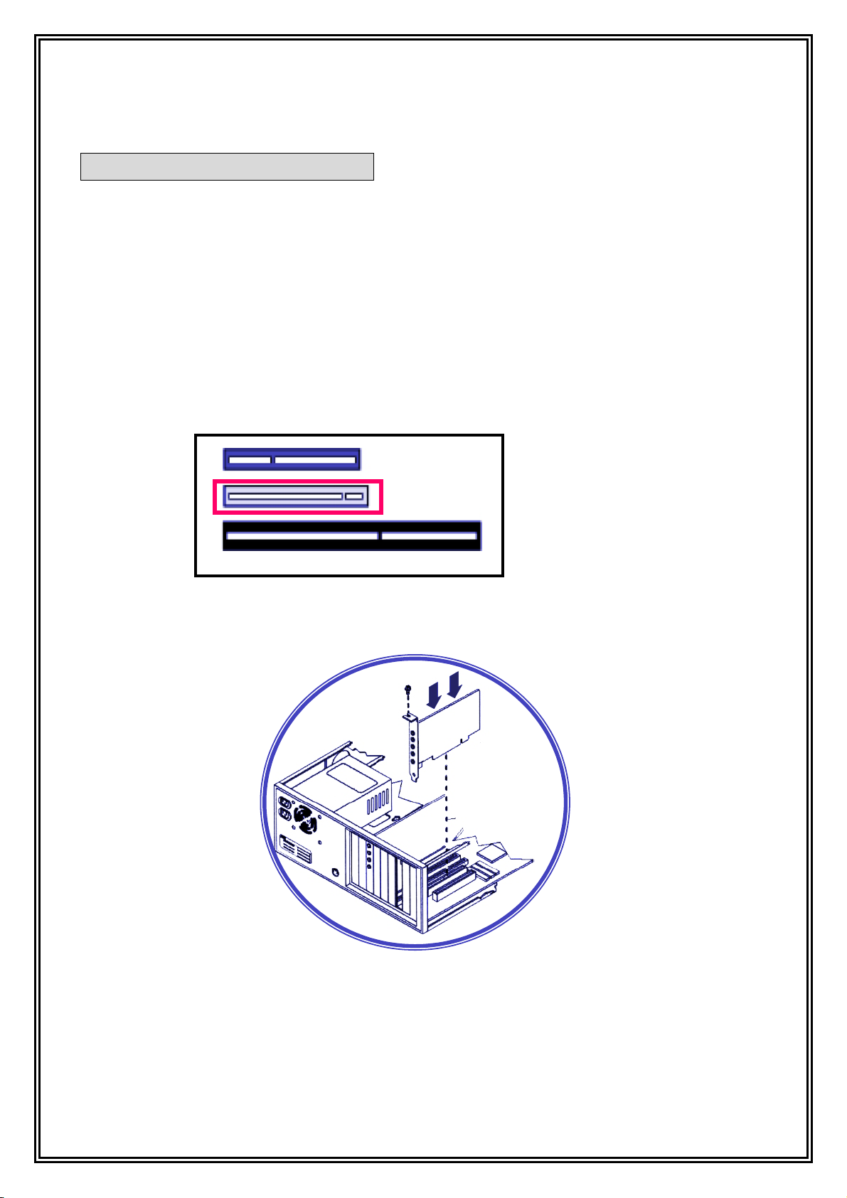
2) Open computer case and Please install as follows:
3) Check to make sure there is a PCI slot available.
AGP (VGA) Slot
< PCI slot >
4) Please install securely in the slot.
PCI Slot
ISA Slot
< PCI slot Installation >
5) Secure the card in place by tightening the screw.
6) Close the case then turn on the computer
4
Page 5
Install System
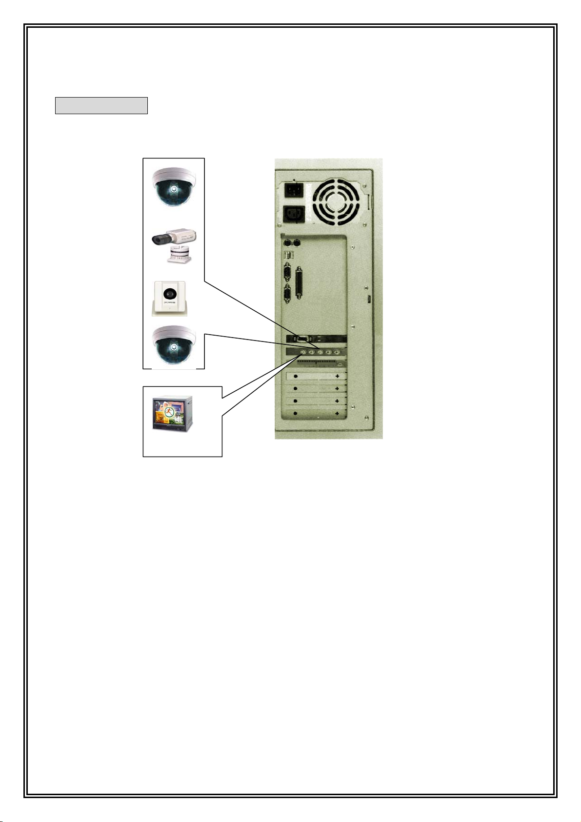
Video Out
A User may connect CCTV camera, video phone, or video out port of any security
system to one of camera input ports on GVC capture card.
Also, a user may use TV out to connect an external analog CCTV monitor.
5
Page 6
Install Software
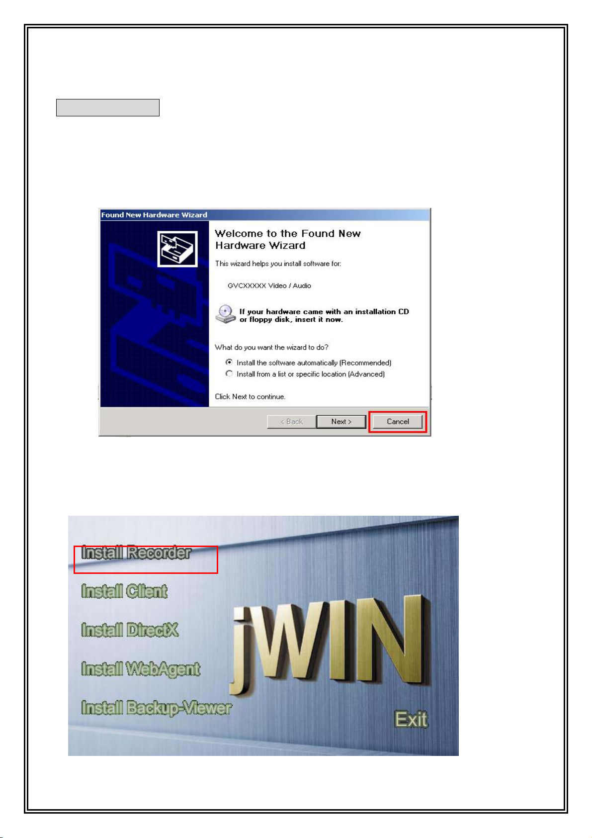
1) After installed jWINSheriff Board, and turn on your computer, automatically
display as below “Found New Hardware Wizard” program. At that time, click all of
“Cancel” button, and finished Wizard program. (according to a type of board and
quantity of board, can be repeated.)
2) To install
CD-ROM drive.
3) Then, the installation program will run automatically. (If not, run 'Autorun.exe' file)
jWINSheriff V4.2 software, You must insert ‘the installation CD' in your
6
Page 7
4) Select "Install Recorder".
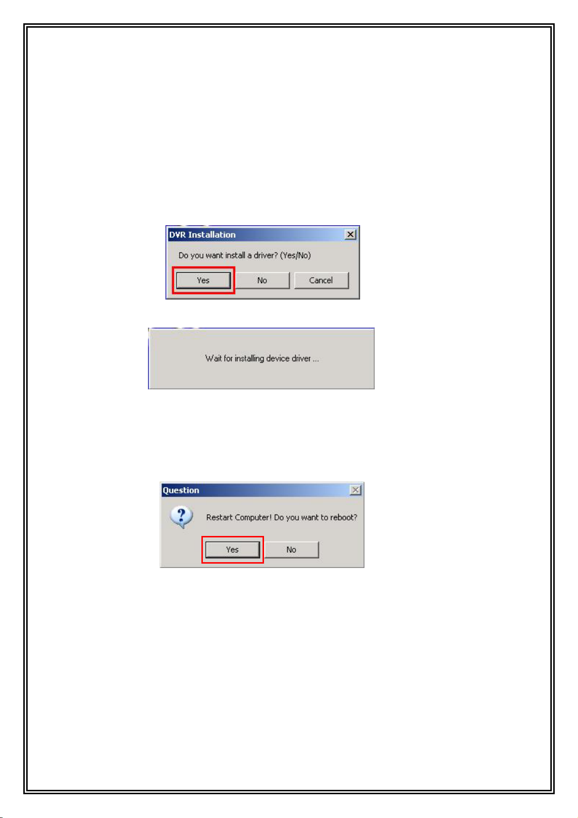
5) Before installation takes place, a dialog box will ask whether it should install with driver.
If you selected “Yes”, it will install the
needed to run this program. If this is your first installation of jWINSheriff on your
Computer, you must select “Yes”)
6) And then Installing device driver.
7) According to indicating the install program, click “Next” program.
jWINSheriff program with driver (The Driver is
8) Reboot computer, if you had done installation successfully. The jWINSheriff
program icon will appear on window of your desktop.
warning!※
jWINSheriff uses a specific data format. So, you must designate the specific
data file by using the setup program’s 'Storage Space' section after installation.
jWINSheriff will not record data without specific jWINSheriff storage space.
7
Page 8

Main Screen Overview
Screen Mode
Channel
Rotation
Minimize/
Close
PTZ
Control
Power
Digital Out
PTZ
Speed Control
PTZ
Extension
Video &
Audio
Recording
Status
Local Viewer: Run Local Viewer[Search]
Warning
Local ViewerSetup
Setup : Run Setup
Minimize/Close : Hide Button DVR Recorder in tray bar, and Close Button[Exit]
Video & Audio Recording Status : Status of Recording about Video and Audio
Warning: Display Warning Message
Screen Mode : Division of Display Screen [1,1/4,2/4,3/4,4/4,1/9,10/9,16,etc..]
Channel Rotation: Automatically Changing Channel
PTZ Control: PTZ basic button
PTZ Speed Control: Slide bar for PTZ moving speed
PTZ Extension: Button about expending PTZ control panel
Digital Out Switch: Switch button about Digital-out on Capture board
Exit: Exit Button
8
Page 9

SETUP
9
Page 10

Preset ID and Password
The preset ID is set in “Administrator,” Password is set in “Admin.”
Setup Tree
General
- Display Device
- Video Input Signal
- Communication Setup(WebCam Server)
- PTZ Setup
- Save Image Quality
- Font
- Use Full screen mode
- Check Daily Reboot
- Use Password
- User Add/Delete
- Windows Shell mode
- Site Name
Sensor / Alarm Setup
Camera / Motion Detection
- Camera Setup
- Motion Setup
- Overlay Setup
- PTZ Receiver Setup
Audio Setup
Schedule Setup
Holiday / Recording Frame
- Holiday Registration
- Event Recording Setup
- Motion recording Setup
- On Time recording Setup
- Sensor recording Setup
Storage Space
ETC
- Using Line Monitor
- Using Alert Mode
- Notify E-mail
10
Page 11
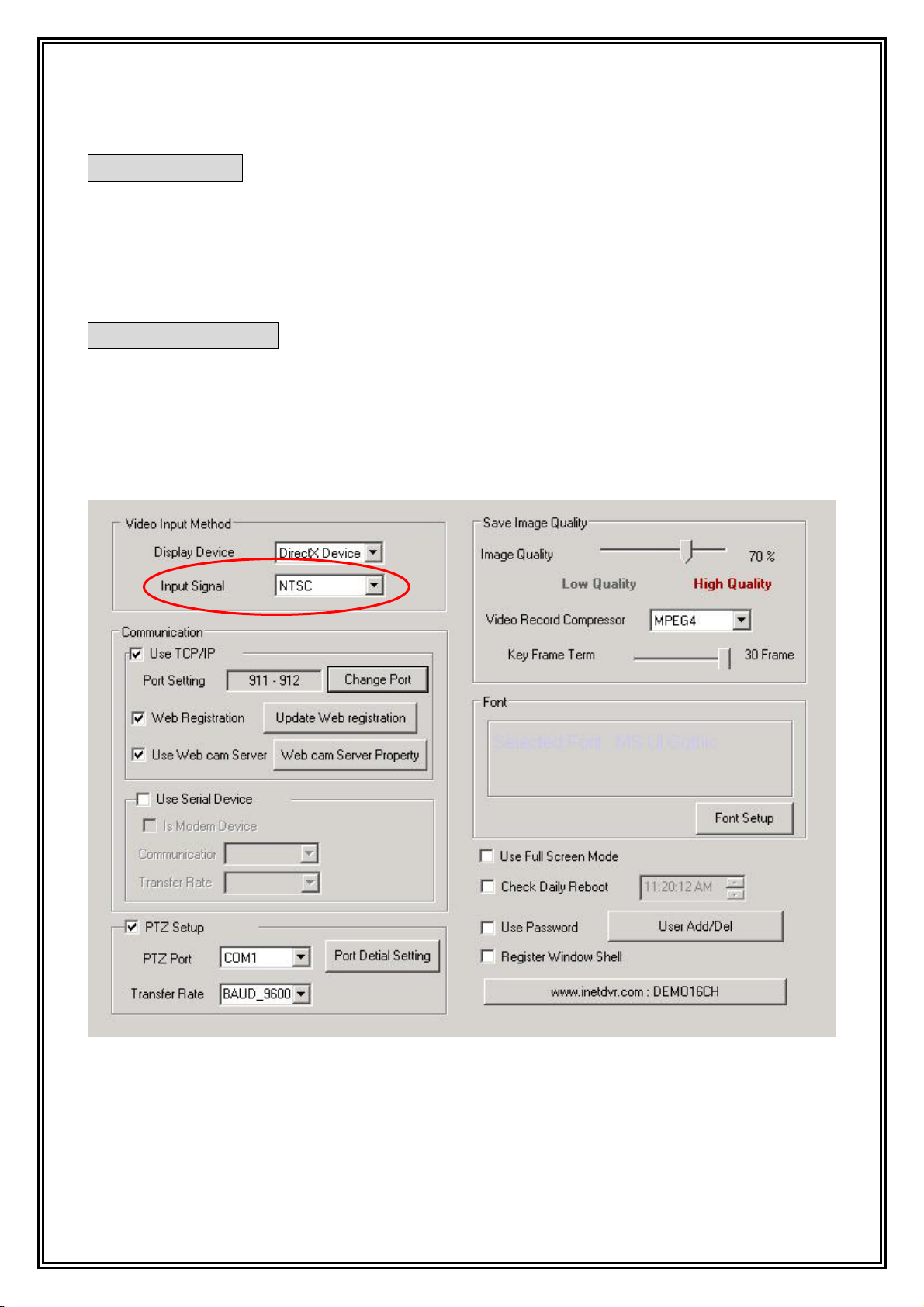
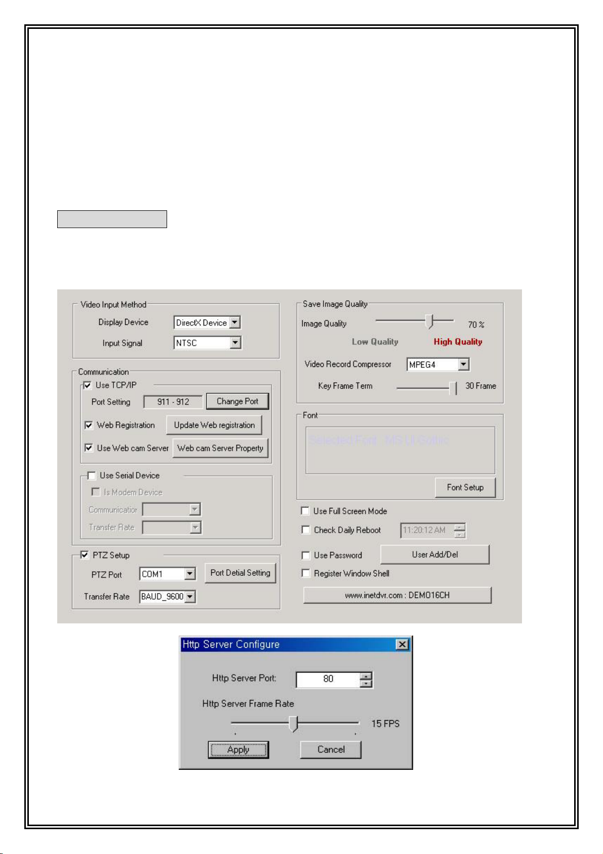
Display Device
Basically, jWINSheriff support DirectX, but the graphic card of your computer
sometimes do not support above DirectX and YUV Overlay. In this case, you must set up
“Display Device” to “RGB Device” (The default value is “RGB Device”.)
Video Input Signal
jWINSheriff support both of Video signal NTSC and PAL type. In NTSC, maximum
recording speed is 30 fps, in PAL TYPE; maximum recording speed is 25fps on each
channel.
11
Page 12
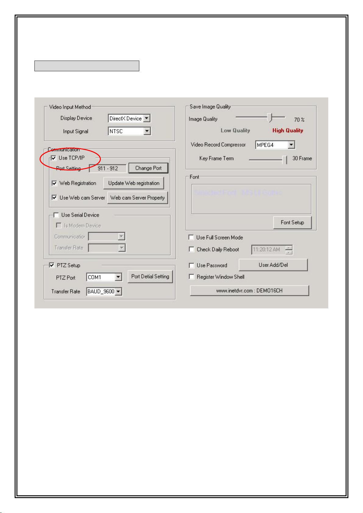
Setup the communication
1) Using TCP/IP
- Check “Use TCP/IP” in Check box.
12
Page 13
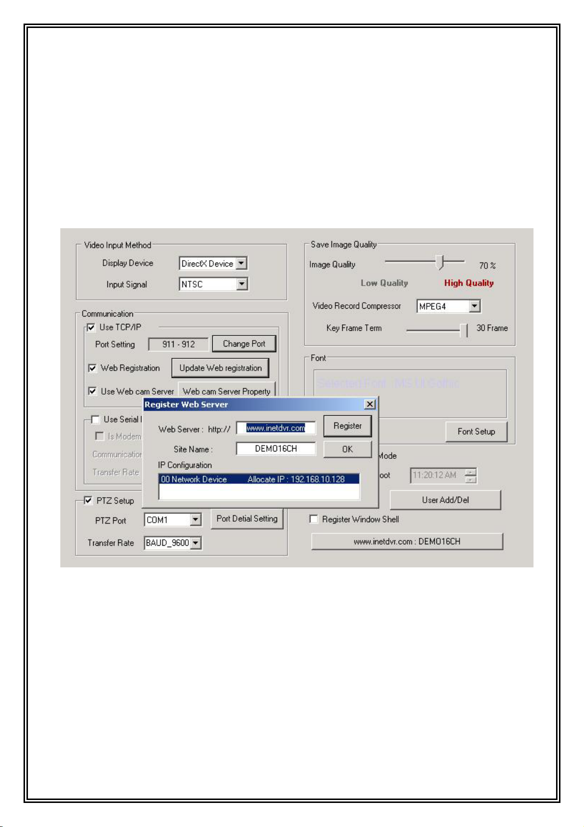
2) Using Dynamic IP by DHCP of ADSL, Cable modem.
- First, verify the network connection and Internet connection is working.
- Check “Use TCP/IP” in Check box.
- Click “Web registration.”
- Click “Register Web server” -> Pop-up window will appear.
- Key in “www.inetdvr.com” in “Web server”
- In “Site Name” key in a characteristics name instead of IP address.
3) Using in network behind Firewall or internal IP.
- To set the Port settings, Select TCP/IP (default value 911 for Video, 912 for Audio),
You must notify it to your network manager for these changes.
(Please inquiry details to your network manager.)
13
Page 14
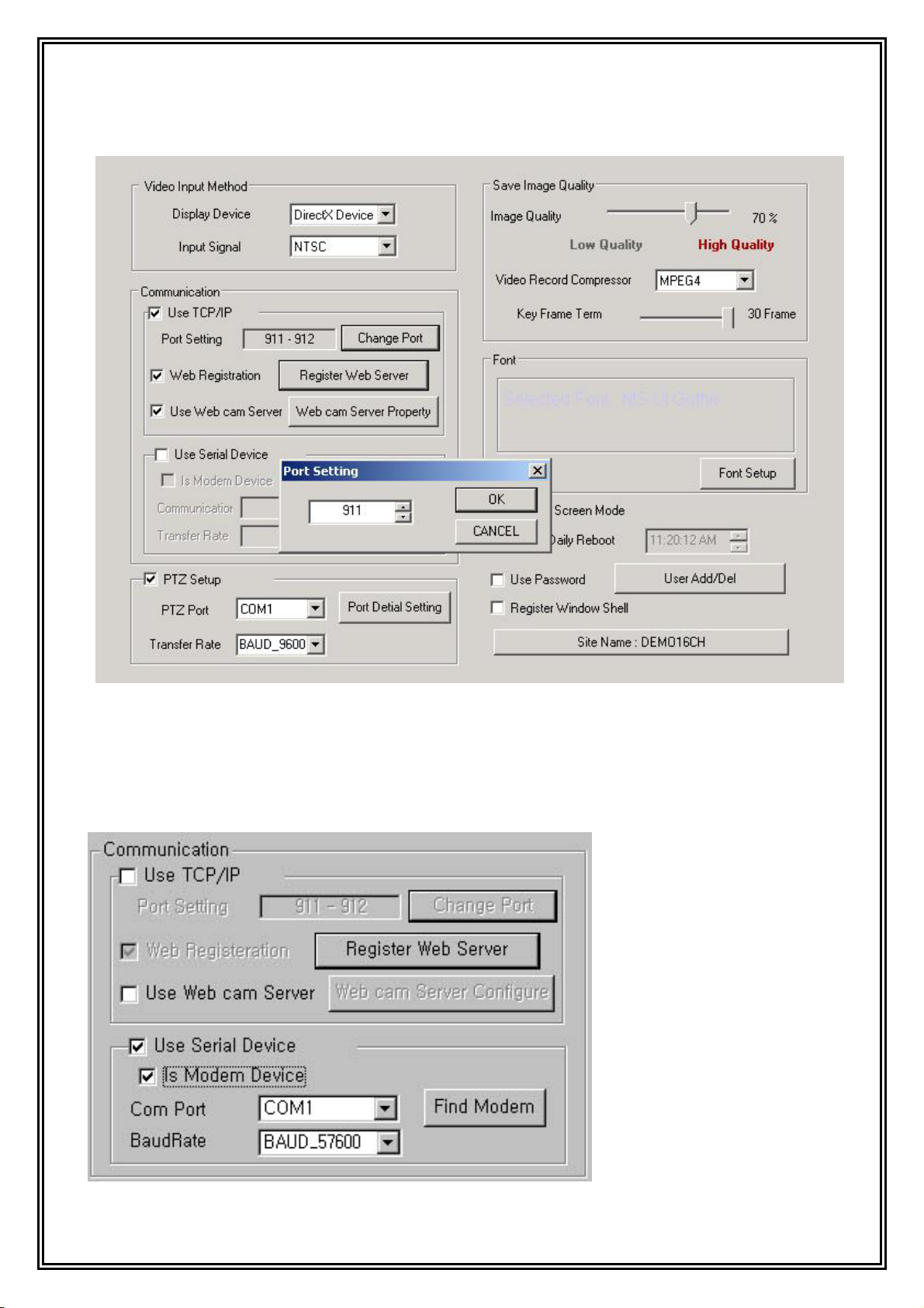
4) Using Serial Device
- Check “Use Serial Device” in check box.
- Set up communication port and transfer rate.
14
Page 15
5) Using PSTN (Public Subscriber Telephone Network) Dialup Modem.
- Check “Use serial device” in check box.
- Check “In Modem device.”
- Click “Find Modem” or set up communication port.
- Set up “Baud rate”
WebCam Server
1) Using a WebCam Server
Even if you have no client program at the remote site you can watch images to using a
web browser. Check “Web Cam Server” for this function.
15
Page 16
The value of default port is 80, but the user can change the value of the default port. If
there is no display of the image due to the firewall. (The remote user can connect the
webcam server to the recorder without the network administrator authorization.
Note:
For broadband T1 and Dial up Connection
The user sets up the frame rate according to the communication speed of the on line
connection. The maximum number of frames that can be viewed is 30fps. The higher the
fps the more CPU resources will be needed from the server.
Therefore, the user can adjust the fps speed of upload from 1fps for PSTN Dial-up modem
or less than 300Kbps, 2fps for 512Kbps and 30fps for 10Mbps on the basis of 4 channels.
If you used Web※ Agent when you changed Web Server Port, WebAgent should be
reinstalled.
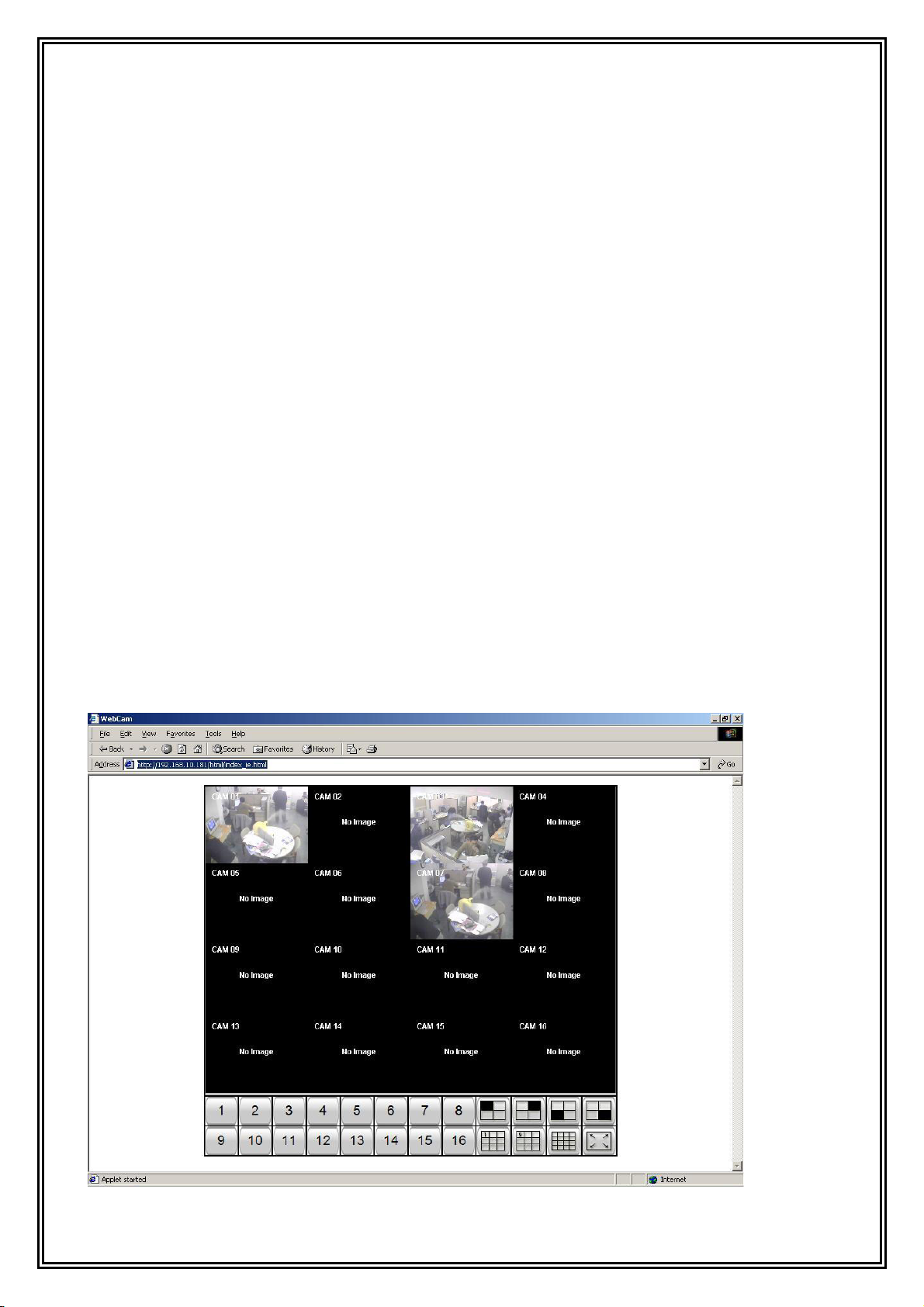
2) Viewer
When the user is monitoring the image through web browser, the user must set up the
IP address of the server and port number, through the WebCam Sever set up port. If
WebCam Server set up default port, that is Web server port, so you could insert just IP
Address on web browser.
For example, enter “http://192.168.10.99” or “http://192.168.10.99/html/index.html” on
the location window of the web browser.
16
Page 17
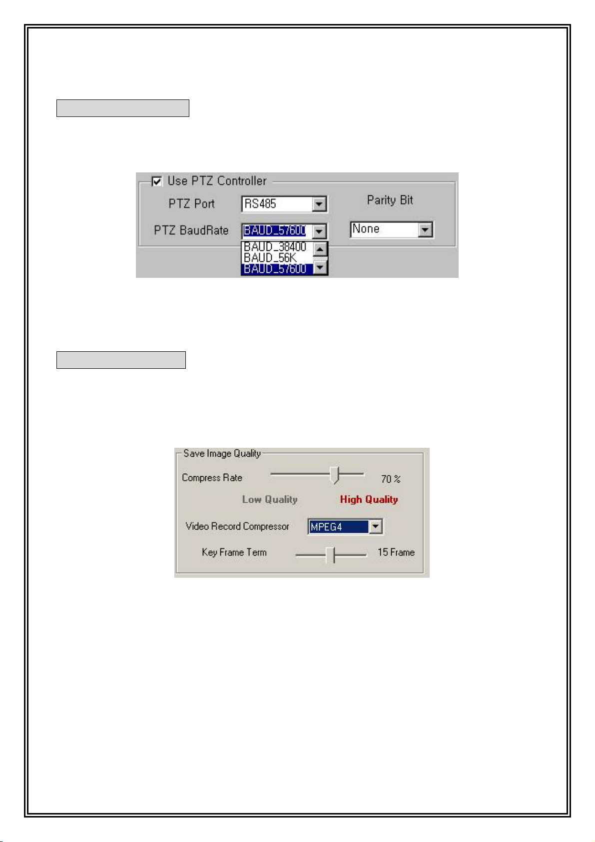
PTZ (Pan Tilt Zoom)
Set up communication port for control PTZ, transfer rate, parity.
The PTZ Receiver uses RS-485 communication protocol, and you can reserve that port for
DVR capture board. “COM1” or “COM2”, can only be used for (RS-232C) protocol.
jWINSheriff supports setting each PTZ Receiver by different ID number (in tab “Set up
Camera”)
Save Image Quality
jWINSheriff supports MJPEG and MPEG4 algorism.
MJPEG, provides higher image quality, While MPEG4 provides a higher compression rate.
When selecting MPEG4, you must to set Key Frame term.
17
Page 18
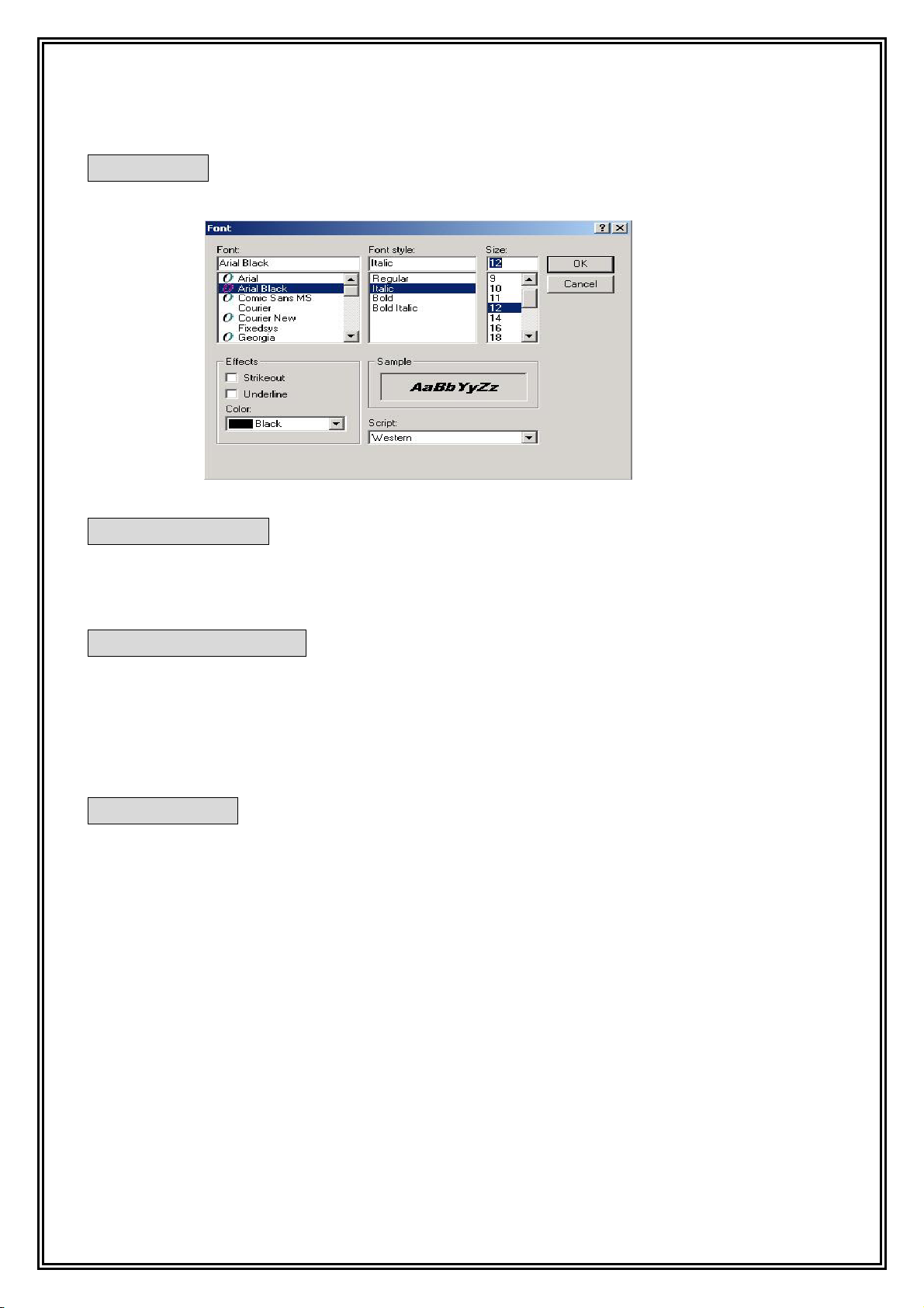
Font Set up
User can change font of camera name.
Full Screen Mode
If there is no keyboard or mouse movement within a 60 second period the screen will
automatically be changed to the full screen mode.
Daily Reboot Feature
When the daily reboot function is checked, the system will automatically reboot itself at
the prescribed time. When systems are running for long periods of time they tend to
accumulate very large memory files which can cause the system to freeze up. This feature
is very useful for assigning dates and times to automatically reboot the system.
Use Password
Only authorized person can use the set-up page to change contents or shut the down.
Default User ID/Password is “Administrator/Admin”, “Anonymous/Guest”
It’s necessary to set authorizations for other User ID’s operation and Remote Access.
Specially, “Anonymous/Guest” is important when you used WebCam Server.
When you accessed Webcam server, the Server will be start to find “anonymous”. If the
User ID is existed, the Server is checked channel which camera channels are shown by
server setup.
Otherwise, If there is no ID:Anonymous (ex, ID:Anonymous was Erased), every camera is
not able to access by anyone.
18
Page 19
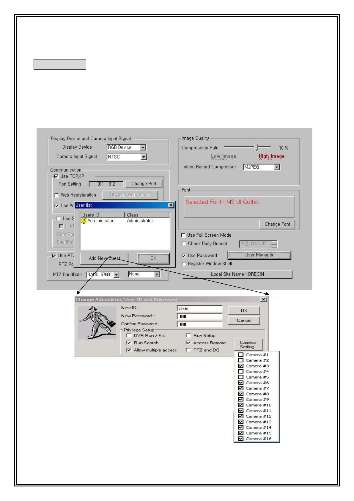
User Add/Del
To register new user, click “User Add/Del” button, and then click “Add new user”.
Insert new ID and Password about new user. In user authority, “allow multiple
Access” have the function that multi user can do simultaneous access.
However, supervisor is not permitted multiple accesses (Person that have authority of
run/end, set up it.)
19
Page 20

Window Shell Mode
If you wanted to use your computer for DVR, Check this box.
If you checked this, after computer rebooting, Only DVR runs on your computer without
any application.
Site Name
This system window with “Site Name” to distinguish another DVR’s from remote client
Program. (This is same with site name of “register Web Server” in “Set up -
communication”.)
20
Page 21
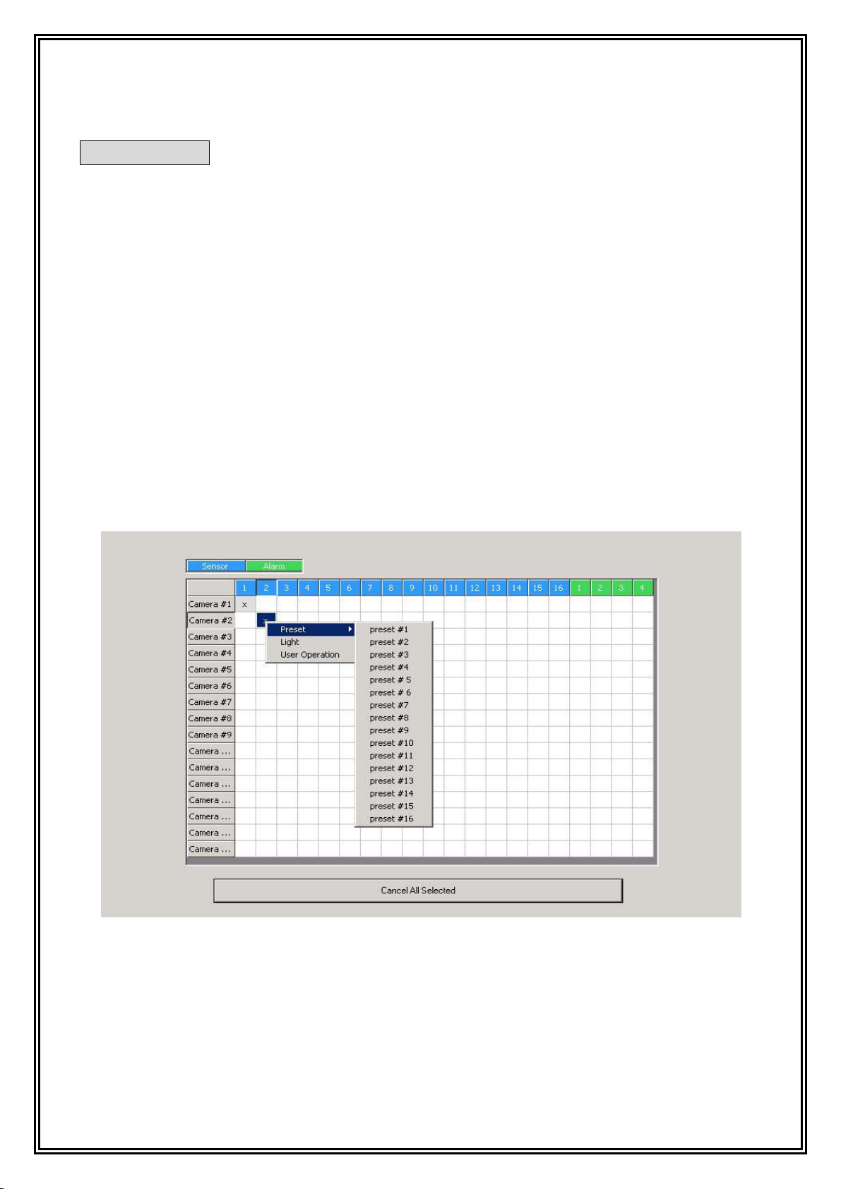
Sensor/Alarm
This section defines the sensor/alarm action.
jWINSheriff supports 2 type of Sensor/alarm action.
“x”: If sensor works, record those images according to schedule.
From above “x,” click right mouse, you can use extension functions (Preset,
Light On, User Operation).
When PTZ was supported,
“P1 ~ P16”: When sensor works, camera operates to preset location.
“L”: When sensor works, turn on light.
“U”: This function controls the Aux 5 of PTZ Controller from user operation.
As above, only PTZ controller is supported. If not so, and you use to alarm control in
DVR Board, you can click alarm number connected with sensor number. You can set up
one Sensor/alarms or sensors/ an alarm.
21
Page 22
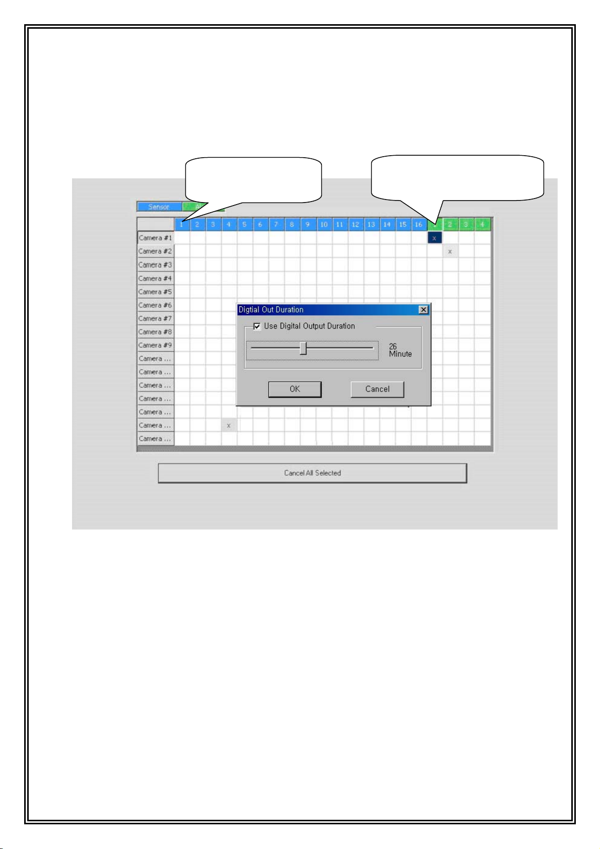
You can set NC (Normal Close), NO (Normal Open) and Alarm out duration.
Digital out is worked by event on schedule, during how long time you set.
It’s not worked when you switched digital out.
For setup NC, NO
Click Sensor number
For setup alarm out duration
Click D/O channel number
22
Page 23

Set up camera connection and resolution
jWINSheriff program can identify camera signal automatically though the camera
connected. When you do not see images (because of camera broken, disconnection of a
cable), ”Video loss” will occur at local or remote monitoring center. The recording
resolution is supported by 320X240, 640X240, 640X480 on NTSC, 384*288, 768*288,
768*576 on PAL. “Don’t display” is a function that will not display on jWINSheriff
Screen, but will continue to record on the DVR.
23
Page 24

Camera/Motion Detection
To set up the Motion detection area, click and drag the left mouse button. To cancel the
area, click and drag the right mouse button. Clicking on the “Detection sensitivity” button,
you can control the sensitivity of Motion Detection.
Also if you couldn’t notify Motion detection area very well, you can change the color of
Motion detection area to other color by clicking “Change detecting point”
24
Page 25

Set up overlay (Advanced Model)
If you use Overlay board (GVC-16R), you must set up brightness, color, etc. of
Overlay board in addition
25
Page 26

Set up types of PTZ Receiver
You can set up different types PTZ receivers.
26
Page 27

Set up Audio
This function is a part that set voice sensitivity compounding camera. User can set up
camera and audio environment to use audio. Click camera #1 button Setting audio, Icon of
speaker shaped come out in lower column part.
“Audio setting”: Lower button is better quality, but file size is getting bigger and bigger.
“Recording method”: Always recording audio: If you can not click this button, audio will
be recorded only when motion detection works.
After connecting a microphone, press “Audio test” button, you can see yellow pulse
signal. If it sounds too small, you should control “Gain” value.
27
Page 28

Recording schedule set up
If you wanted to compound schedule with “Audio(A)”,“Sensor(S),” “Motion detection (M)”,
“ON-time (T), after clicked one of those buttons and drag with push on left mouse button.
If you want to record Audio, audio is set up on schedule.※
if you want to record external device, sensor is set up on schedule.
+
28
Page 29

Holiday Registration
You can program holidays, to record or not to record on the registered holiday.
29
Page 30

Motion Record Set up(Each Camera)
To activate “Alarm in Detection” and “Sensor in Detection,” click on the check box
marked ALARM IN DETECTION.
The post alarm recording may be adjusted from 0 to 60 seconds by sliding the bar
forward or backwards. This will allow recording to continue after motion has stopped.
PreAlarm Recording Setup(Each Camera)
You can set the Pre Alarm Recording time from 0 to 10 seconds. This will retain the
recording of up to 10 seconds before the event occurs or the alarm is triggered.
Motion Detect Record Setup(Each Camera)
if you want to record image when Motion-Event occur, Check the check box about
“Alarm when detected” and set slide bar for recording property.
Sensor Record Set up(Each Camera)
If you want to record image when Sensor-Input occur, Check the check box about “Alarm
when signal input” and set slide bar for recording property.
On-Time Record set up(Each Camera)
When Ontime-Recording occurs, an image is recorded 15 fps for 7 second.
30
Page 31

Set up storage space
Following the initial installation of the software you must set up your disk storage space
allocation. This allocation of storage space is user defined and can be allocated in several
different hard discs. Storage space is displayed in 3 types.
Application space : Space that installed OS, DVR Program and some Application
program.
Already Created data space : Space that set already to data space of DVR.
Able to create data space : Data space except reserved user free space in empty
space of drive.
Notice: ※ Free Drive space is necessary for the stability of your system to work well. So when DVR shows
Free Drive Space , DVR calculate Free Drive space except the Space for the System Work.
-See the pie chart for making “Storage Space”.
-Select Driver where you to make storage space to save recording data.
-Move slide bar to how big size you want.
-Check select box and click “Make Storage Space”.
31
Page 32

Using Line Monitor
You can connect an additional monitor to view the camera activity using the TV OUT
RCA connection on DVR board. Select the line monitor function to display the desired
camera output. The images then be displayed in full screen by rotation.
※ If you make system with more than two pieces of board, you have to connect monitor to
Line monitor port of each board.
32
Page 33

Using Alert Mode
When sensor input is triggered, or detects motion from server system with registration of
pre-designated client communication address, the detected data information is transmitted
with alarm to predestinated remote multi viewer when connecting in a network.
Auto Release Alert Event
To automatically release an alert event, check the Auto Release Alert box.
33
Page 34

Notify E-mail
As detecting sensor, motion set in alert mode, Final image of camera and log data
detected is informed to assigned E-mail address .
(For example: “dvr@dvr.com;bbb@dvr.com.net;mailccc@dvr.com”)
34
Page 35

Local Viewer
(Search)
35
Page 36

Screen Overview
Save Print
Backup
Motion detect play
Backup
Viewer
Event
List
Screen Division
Multi-Speed play
Recording
Zoom Ctrl
Brightness
Backlight
Play Control
Recording
Recording
Date & Time
Date & Time
Exit
Status
Motion
Sensitivity
It’s displayed when jWINSheriff’ setup is for NTSC. [General tab in Setup See pg.11]
36
Page 37

It’s displayed when jWINSheriff’ setup is for PAL. [General tab in Setup See pg.11]
Cause PAL Type has bigger image size than NTSC
Save Print
Backup
Motion detect play
Backup
Viewer
Event
List
Screen Division
Multi-Speed play
Zoom Ctrl
Brightness
Motion
Sensitivity
Backlight
Recording
Date & Time
Recording
Status
Play Control
Exit
37
Page 38

Running Search program
From main screen click “Local Viewer (Search)” button.
Choice Date and Time
The Date has data, is marked in highlight on displayed calendar. Also the time is marked
in highlight on selected date;
Click the date and time, and the time which has data, is colored blue. Click on the blued
data to display the data to the screen.
Choice channel
After selecting the date and time, All channels are displayed on screen at first time. If you
wanted to search one channel, click the mouse on a channel window you want. The
window will be outlined red box. All controls will work only within the selected channel.
38
Page 39

Play operation
The slide bar of play panel corresponds to one hour. (the selected time)
First End: It displays the first image of selected time.
1 Frame Backward: Backward retrieval per a 1 frame unit.
Backward: Backward retrieval. The image recorded by MPEG4 is skipping the image of
key frame unit to next key frame. Fast backward is same.
Fast Backward: Fast backward retrieval..
Stop: Stop to play image.
Fast Forward: Fast forward retrieval. The speed is a selected what times speed you
selected.
Forward: Normal speed retrieval.
1 Frame Forward: Forward retrieval per a 1 frame unit.
Last End: It displays the last image of selected time.
Full screen display
Double click the channel that you want to display, a full screen will display.
Screen division
jWINSheriff ‘s retrieval program supports 1, 4, 9, 16 division screen.
Press division button that you want, and display that screen.
39
Page 40

Change property of a selected channel
Each button is enabled when a channel is selected.
if you want to change each property of the channel, move the slide bar to + or - .
Also left/right arrow key is able to move slider bar.
If you toggled each button, the property is reset.
Zoom In / Zoom out
Brightness Control
Backlight
Motion detect Sensitive
Motion Grid Color
Image Zoom in / Zoom out
Slide bar to Control
If you move slide bar to +/-, Image on selected channel is enlarged.
Control the brightness of Image
The Brightness of image is selected, is controlled by moving sliding bar.
Control Backlight of Image
The backlight is adjusted on Image.
Control Sensitivity of Motion Detection
The sensitivity of motion detection increases or decreases the Image.
Multi Speed play
Back-up Multi-Speed play
40
Page 41

If you want to watch recorded data on Fast Forward/Fast backward, or watch the Data
flame by flame, Set the display speed to what do you want(1x speed play is default. ) and
then clicked Fast Forward or Fast Backward button.
Print Back-up
Motion Detect Mode
Each Button is enabled when a channel is selected.
Save
To save an image press the save button. The selected channel will be saved as a file
format of “camera#_data_time.JPG”.
Print
Press this button to preview the image. Press Print again to print the image.
Motion detect retrieval Mode
To retrieve data that has been recorded during motion detection of a defined area of the
screen, hold down the control key and right click on the mouse and drag the area you want
to review view.
To cancel this function hold down the shift key while right clicking on the mouse key.
Change the color of motion detection area
As the color of motion detection area is difficult to distinguish against the background color
in the image, you can change the color of the detection area. To activated the color change
click on the grid color button and adjust the slide bar to change the color.
Change the sensitivity of motion detection
To activated the sensitivity of motion detection click on the sensitivity button and adjust the
slide bar to change the sensitivity.
41
Page 42

Back up
1. AVI Back UP
jWINSheriff support the file format of AVI for Multimedia use with Windows OS.
- The starting and ending time of the data back up should not exceed 600MB.
- Select the drive that you want. If you want to back up in CD, you should have the
software such as “Direct CD”, and select the “CD” drive to back up.
- And select CODEC, the basic CODEC is MPEG4. If you do not select “Default Codec”
in check box, a list of installed CODEC will be displayed, select the CODEC that you
want.
- Click the “Backup” button, start it.
2. DAT Back up
DAT Back up is a method that jWIN uses to back up the raw data of jWINSheriff,.
To invoke the feature;
- Check “DAT” in Check Box.
- Key in the start time and the end time.
- Select the drive letter that you want to back up.
- Click the “Backup” button, and start.
3. Playback of DAT’ data
- Press the “Backup View” button.
- The function key controls are the same as retrieval program.
42
Page 43

Retrieval Event List
This function includes the running time and end time of DVR system, the controlled
contents for running time and the event of sensor in action.
If you want to return another function from “Event List”, click again the
jWINSheriff
button. (Toggle Button). When you want to display the image, double click the event that
you want, and then come out the retrieval screen, display the image that event occurred.
(If the image at that time is not recorded, no change the screen.)
”Today Event”: Display today event on Event List
”Day Unit Event”: If you clicked on “Day unit Event”, date list is shown on left side. And
then clicked which day you want to search, event list is shown on right side.
“Search Special Event”: This function is that you want to see the event in particular.
You can see by “Set up period”, “Search filter”.
43
Page 44

Remote Viewer
44
Page 45

Screen Overview
To Single Site
Connected
Site List
PTZ Image Quality Save Print
To Muti Site
Warning Sign
Exit
Data Viewer
Display
Connect
Manager
Site
Manager
Setting
Manager
45
Page 46

Remote
Digital Out
VidChat
Search
Alarm
Switch Control
Setup
To Next Site To Prev/Next site
Camera & Audio
Control & Stat
PTZ Control
46
Page 47

Registration Site information
To see DVR’s image of remote site in Client program, you must register the site
information.
- Press the “Site Manager” button.
- The pop-up window “Site Manager” will appear.
- Choose a site name then enter the name into site manager.
- Select the connect media.
- In case TCP/IP: Key in the IP address and IP port (Default 911) number.
- In case Leased Line: Key in communication port and Baud rate.
- In case PSTN: Tel NO, Communication port, Modem speed.
- In case Web Server: When jWINSheriff‘s recorder has Dynamic IP, client is
connected by getting information from Web Server about registered recorder. Because
Dynamic IP is changed frequently, Client couldn’t connect with Recorder directly. If
jWINSheriff checked the “Web Registration” on Recorder’s Setup, jWINSheriff will
send a changed IP to Web Sever when jWINSheriff had changed IP. The Client would
now connected with changed jWINSheriff IP by setting of communication to Web
Server.
- Key in “ID” and “Password”. (Registered in “User Add” of set-up program.)
If you want to key in the ID and Password whenever you use as security, cancel to check
in check box, and do not need to key in the ID and Password. But, In case connection
method is “Web Server”, mean not ID, Password in DVR recorder but ID and Password
as same as Web Server (www.inetdvr.com).
47
Page 48

Storage Space Info
Client’s Recording data has different System to Recorder, so each Site needs own storage
Space. Also each DVR server needs their own storage space, and a hard disk driver is
possible to get a server’s storage space.
For example, if your computer has five hard disks driver, your computer is able to
record data from five DVR Severs maximally.
Recording Data from A DVR server needs a hard disk driver for storage space.
If you selected “storage space” tab in “Site manager”, this picture shows up.
It’s about Storage Space information of Client computer.
1. Select a DVR server as like below picture.
2. When you selected a sever, hard disk driver’s information is displayed
3. select a hard disk driver, and click “Make Storage Media”
48
Page 49

4. A window is popped up, and set storage space for recording by slide bar.
and click “Make Storage Media”
5. Made storage space is displayed with Green as like that.
and go to “schedule” tab in “Site Manager”
49
Page 50

Remote Recording Schedule
When Client is enabled you can save recording data from (audio and, or video) based on
your predetermined schedule setting.
If your client computer has storage space available, it will be able to record data based on
the set schedule.
50
Page 51

Connect Site
The registered sites come out at “Unbooked Sites”, double click the site that you want to
connect, and if it’s connected with the site, come out the site name at “Sites on
connection”. And press “OK” button, disappear the pop-up window, come out the
connected sites at upper right side.
Monitoring Live image
The Monitoring Live image feature supports two types. One is the monitoring of a live
image of selected cameras at all sites, the other is the monitoring of a live image of all
cameras at a particular site.
Monitoring the selected cameras at all sites : After connecting to a site, a list of
cameras connected will displayed. Click camera button that you want to display the live
image. If you wanted to see cameras at another site, click the “Prev” button below or
select another site And follow the same instructions. If you wanted to get the audio data,
click the “audio” button corresponding to camera.
51
Page 52

Monitoring all cameras at a single site: Click the “Single Site” button, display the images
of
Cameras connected. When you want to see the other site, press the arrow key below.
The logging files of connection status
Push the F9 Key, display the status of connection.
52
Page 53

Alarm Information
Set up the alarm mode: if you clicked “Warning”, window about “Alarm Information” is
popped up.
On this window, if you check the Check-box “use Alarm window”, ”Alarm Information “is
popped up when Client got Alarm event from jWINSheriff . And this window display
information as like “Site Name”, “camera channel”, “Alarm Type”, “Time”
On Multi size, when Client got Alarm event from recorder, Warning button is twinkle.
If you clicked Warning Button, Window that has Alarm Event information, pop up
On Single Site, according to Warning signal, Warning button is turned on.
After Warning Occurred at Recorder and Remote viewer get warning signal, you could turn
off the warning at Recorder from Client, if you have ID that has authority of setup.
53
Page 54

Setting Manager
“Setting Manager”, is used for unattended mode settings for all communications.
-Unattended mode: if Alarm occurred from registered Site, Site is connected automatically
by unattended mode for warning signal.
54
Page 55

Selecting the channel and the layout of channel
If you select a channel which has an image, functional buttons (control PTZ, Recording,
Print, canceling the image’s transmit, control the image quality) are enable to work.
Save
Print
PTZ Image Quality
Control PTZ (Pan Tilt Zoom)
The PTZ control function is activated only for authorized users. This function is activated
for authorized ID users only.
55
Page 56

Setting up the image quality to be transmitted
You can set up the image quality.
Transmitted Image count per second is changed by setting of the image quality.
Cause higher Quality Image is Bigger size of Data.
Save the transmitted image
If you wanted to save an image which you selected a channel in a single site, click
“Save” Button, then you could see the window to save jpg format file.
in Multi Site, if you clicked save button, the channel is selected, is recording by avi file
format to the path where you selected on Setting manager windows
If the site name or camera name do not supported a language in Client program (For
example: Local DVR: Chinese, Client: English), this may cause an identification problem.
You may need to change camera name, etc.
56
Page 57

Print out the transmitted image
You can print out the transmitted image.
57
Page 58

Selection the site and the layout of channel
Clicking “site name ” you want on the connected sites list, it is enable to click “Camera
button, Audio button ,Remote Setup”, “Digital I/O” and etc. The activation of button is
different according to the authority of ID.
Digital-out
Switch
VidChat
Search
Remote
Control
Digital-Out Switch
It’s come out when user who has authority about setup.
Control the Digital-out switch on server (DVR).
VidChat
- Pressing this button, cone out the icon “Voice Communication” in tray, if connection Is
success, the icon is blinking. If connection is failure, come out an error message. It’s
based on H232 Protocol, so if you used vidchat under router or firewall, you might
ask it to your network manager to use [ref H232 protocol].
58
Page 59

Search
As same as Digital out Switch, It’s cone out when the User has authority about search.
Selecting the channel that you want, come out the date (the color become changes in
the calendar that is recorded, and select the date, come out the time interval of that date.
Selecting the time, it is activated the slider-bar and the button of retrieval, and can start to
retrieval it. It work as same as Search on server (DVR).
Remote Control
You can modify the information of setup in remote site. This operation is as same as
DVR’s. Press the button “OK”, The server (DVR) restart, automatically reconnect.
59
Page 60

Dual Monitor
Two client applications is able to run as like picture on a computer, if your VGA graphic card supported dual
monitor.
1. If you have VGA card that support dual monitor, setup using dual monitor at Screen’s property.
2. Click and run Client Icon on Screen.
3. Click minimized button to hide client.
4. Click and run Client Icon on screen again.
5. Click Client Icon on taskbar for full-screen
The operation is each client program is running in a computer, so you can connect maximum 32 site [16 site
*2 ]] and display 32 channel’s image.
each client is not linked with and run separately.
60
Page 61

WebAgent
61
Page 62

Web Agent Install
This Picture shows up when you insert Install CD
Click “Install WebAgent” Button on Screen
Web Agent Setting
Use DVR Sever: if WebAgent was installed on a computer that had DVR and Set
WebCam Server, Check on this button.
USE Webserver to: If WebAgent was installed on a computer that is work server, and
user didn’t check WebCam server, check this radio button, and you have to select the
folder where “index.html” is copied.
62
Page 63

Display Mode: Recommended Auto Display mode (Change Display mode automatically
by connected Camera count).
If you selected other mode (4, 8, 16 channel), you can choose channel which you want
to watch.
Check “Use Control”: Check “check box” for PTZ& Digital-Out Switch on Web
Check “Use Window to check UserID”: If you checked this Check-BOX, you have to
Login on Web-Agent page.
After all, Click “OK”, it makes a file for web service.
63
Page 64

How to use Web Agent by client
Run Internet Explorer, write as like
”WebAgent installed server’s IP Address: port/ WebAgent installed folder path/”
Default: WebAgent
"
If it was connected DVR site, we could see Web Agent on Internet Explorer.
If your computer doesn’t have “Web Agent”,
Window pop up and ask installing “Web Agent” pleases clicks “yes”
64
Page 65

If Install was Success, we could see below picture
(If Agent has Black Screen, Codec is not installed. Install MPEG4 Codec)
If WebAgent was checked “Use Window to check UserID”, this window shows up for
Login.
and then you can see connected WebAgent as like this picture
65
Page 66

How to use Web Agent
You can see menu when you clicked right mouse button on screen
Display Mode
Screen Display mode is changed what you selected to 1, 4, 9, 16 division mode.
Quality
If you changed Quality, Displayed image size is changed.
Also when you changed Quality, you have to consider about transmission speed of your
system. Cause, if you changed quality to high, transmission of image would be bigger
size than low quality image.
Disconnect
If you clicked this button, your web page is disconnected from WebAgent.
66
Page 67

Audio
If you clicked this button, on control bar Speaker Icon is changed color to red, and then
WebAgent play audio data if the selected channel had audio data. Also transmission
speed is considered what your system has.
Save Image
If you clicked this button, you can save an image on selected channel to your computer.
67
Page 68

Web service
68
Page 69

This is Web service for jWINSheriff. It’s mentioned jWINSheriff ‘s Setup page
[Web server’s registration].
When User is Used Dynamic IP by DHCP of ADSL, Cable modem, this service make user
be easy to watch Recorder. Because ,in dynamic IP, Recorder’s IP is change every time
when Computer is turn on. So Remote Viewer couldn’t work well.
If user who has Dynamic IP, register Recorder on jWINSheriff site, User could watch
the Recorder’s image on Web page.
It doesn’t need remote viewer, and needs a few condition as like setting about web
registration, etc..
69
Page 70

There is two way to watch.
One is jpg watch and the other way to connecting is mpeg.
It works as like as ‘WebAgent’.
Operation is as same as WebAgent,[Ref WebAgent]
Operation is as same as WebAgent,[Ref WebAgent]
70
Page 71

1. If you connected Web page www.inetdvr.com, Login page is shown up.
2. if you don’t have ID and password, click ,
and sign up.
71
Page 72

3. when you finish Register, you’ll see this page.
click “Add Site”, and register Site.
Machine Name
ID of The Machine
Password of The Machine
4. After site register, do as like Fig.
5. If you want to connect to jpg, click jpg
or if you want to connect to mpeg with Audio, some functions, click mpeg.
to Connect Mpeg is worked as same as WebAgent.
6. If you want to edit site information, click
to edit site.
7. If you want to delete site, click to delete site.
72
 Loading...