

Page 1
MB124200311
SERVICE MANUAL
MICRO COMPONENT MD SYSTEM
UX-J55MD
Area suffix
UB -------------------- Hong Kong
123
456
789
10 0 +10
DISC UP
TITLE/EDIT
GROUP SKIP GROUP SKIP
GROUP TITLE
DISC DOWN
CD MD TAPE
GROUP REC
REC
REC
ON/OFF
TIME
SPEED
TAPE
MD&TAPE
MD
REC
REC
REC
CLOCK/
PLAY
TIMER
REPEAT
MODE
SLEEP
BASS/
DIMMER
A.STANDBY
TREBLE
BEEP
SHIFT AHB PRO
LP:
RM-SUXJ55MDU REMOTE CONTROL
STANDBY/ON
DISP/CHARA
CANCEL
ENTER
TITLE SEARCH
FM/AM
CD REC
MODE
MODE
MODE
VOLUME
STANDBY/ON
AUTO REVERSE
MICRO COMPONENT MD SYSTEM UX-J55MD
DISC LOADING MECHANISM
DOWN
DISC
SELECT
SET
/AUX
FM
REV.
/
CD/MD TAPE
CD1 CD2 CD3 CD4 CD5
5-CD CHANGER, PLAY&EXCHANGE
PHONES
UP
5-CD
MD REC
AUX/DVD
FM/AM
REV.MODE
VOLUME
AHB PRO
+
Ð
TABLE OF CONTENTS
1 PRECAUTION. . . . . . . . . . . . . . . . . . . . . . . . . . . . . . . . . . . . . . . . . . . . . . . . . . . . . . . . . . . . . . . . . . . . . . . . . 1-3
2 SPECIFIC SERVICE INSTRUCTIONS. . . . . . . . . . . . . . . . . . . . . . . . . . . . . . . . . . . . . . . . . . . . . . . . . . . . . . 1-7
3 DISASSEMBLY . . . . . . . . . . . . . . . . . . . . . . . . . . . . . . . . . . . . . . . . . . . . . . . . . . . . . . . . . . . . . . . . . . . . . . . 1-8
4 ADJUSTMENT . . . . . . . . . . . . . . . . . . . . . . . . . . . . . . . . . . . . . . . . . . . . . . . . . . . . . . . . . . . . . . . . . . . . . . . 1-43
5 TROUBLESHOOTING . . . . . . . . . . . . . . . . . . . . . . . . . . . . . . . . . . . . . . . . . . . . . . . . . . . . . . . . . . . . . . . . . 1-47
COPYRIGHT © 2003 VICTOR COMPANY OF JAPAN, LIMITED
No.MB124
2003/11
Page 2

SPECIFICATION
Amplifier Output Power (IEC 268-3) 40 W (20 W + 20 W) at 4 & (MAX.), 30 W (15 W + 15 W) at 4 & (10 % THD)
Audio input sensitivity/
Impedance (at 1 kHz)
Speakers/Impedence 4 Ω - 16Ω
Tuner FM tuning range 87.50 MHz 108.00 MHz
AM tuning range 531 kHz 1 710 kHz (at 9 kHz channel spacing)
CD player CD Capacity 5 CDs
Dynamic range 87 dB
Signal-to-noise ratio 90 dB
Wow and flutter Immeasurable
MD recorder Audio playing system MiniDisc digital audio system
Recording system Magneto-optical overwrite system
Reading system Non-contact, semiconductor laser pickup (lamda=780 nm)
Error correction system CIRC (Cross Interleave Reed Solomon Code)
Recording/Playback time
(when using a 80-minute MD)
Sampling frequency 44.1 kHz
Audio compression system ATRAC (Adaptive TRansform Acoustic Coding)/ATRAC3 (MDLP)
Cassette deck Frequency response Normal (type I):60 Hz 14 000 Hz
Wow and flutter 0.15 % (WRMS)
General Power requirement AC 230 V~, 50 Hz
Power consumption: At operation 50 W
On standby 11.8 W, 0.9 W (in Power Save)
Dimensions (approx.) 175 mm × 239.5 mm × 378 mm (W/H/D)
Mass (approx.) 7.8 kg
Analog input:AUX/DVD 400 mV/47 kΩ (at "Input LEVEL 1")
200 mV/47 kΩ (at "Input LEVEL 2")
530 kHz 1 710 kHz (at 10 kHz channel spacing)
SP:80 minutes
LP2:160 minutes
LP4:320 minutes
Design and specifications are subject to change without notice.
1-2 (No.MB124)
Page 3
SECTION 1
PRECAUTION
1.1 Safety Precautions
(1) This design of th is product contains special hardw are and
many circuits and components specially for safety purposes. For continued protection, no changes should be made
to the original design unless authorized in writing by the
manufacturer. Replacement parts must be identical to
those used in the original circuits. Services should be performed by qualified personnel only.
(2) Alterations of the design or circuitry of the product should
not be made. Any design alterations of the product should
not be made. Any design alterations or additions will void
the manufacturers warranty and will further relieve the
manufacture of responsibility for personal injury or property
damage resulting therefrom.
(3) Many electrical and mechanical parts in the products have
special safety-related characteristics. These characteristics are often not evident from visual inspection nor can the
protection afforded by them necessarily be obtained by using replacement components rated for higher voltage, wattage, etc. Replacement parts which have these special
safety characteristics are identified in the Parts List of Service Manual. Electrical components having such features
are identified by shading on the schematics and by ( ) on
the Parts List in the Service Manual. The use of a substitute
replacement which does not have the same safety characteristics as the recommended replacement parts shown in
the Parts List of Service Manual may create shock, fire, or
other hazards.
(4) The leads in the products are routed and dressed with ties,
clamps, tubings, barriers and the like to be separated from
live parts, high temperature parts, moving parts and/or
sharp edges for the prevention of electric shock and fire
hazard. When service is required, the original lead routing
and dress should be observed, and it should be confirmed
that they have been returned to normal, after reassembling.
(5) Leakage shock hazard testing
After reassembling the product, always perform an isolation check on the exposed metal parts of the product (antenna terminals, knobs, metal cabinet, screw heads,
headphone jack, control shafts, etc.) to be sure the product
is safe to operate without danger of electrical shock.Do not
use a line isolation transformer during this check.
• Plug the AC line cord directly into the AC outlet. Using a
"Leakage Current Tester", measure the leakage current
from each exposed metal parts of the cabinet, particularly any exposed metal part having a return path to the
chassis, to a known good earth ground. Any leakage current must not exceed 0.5mA AC (r.m.s.).
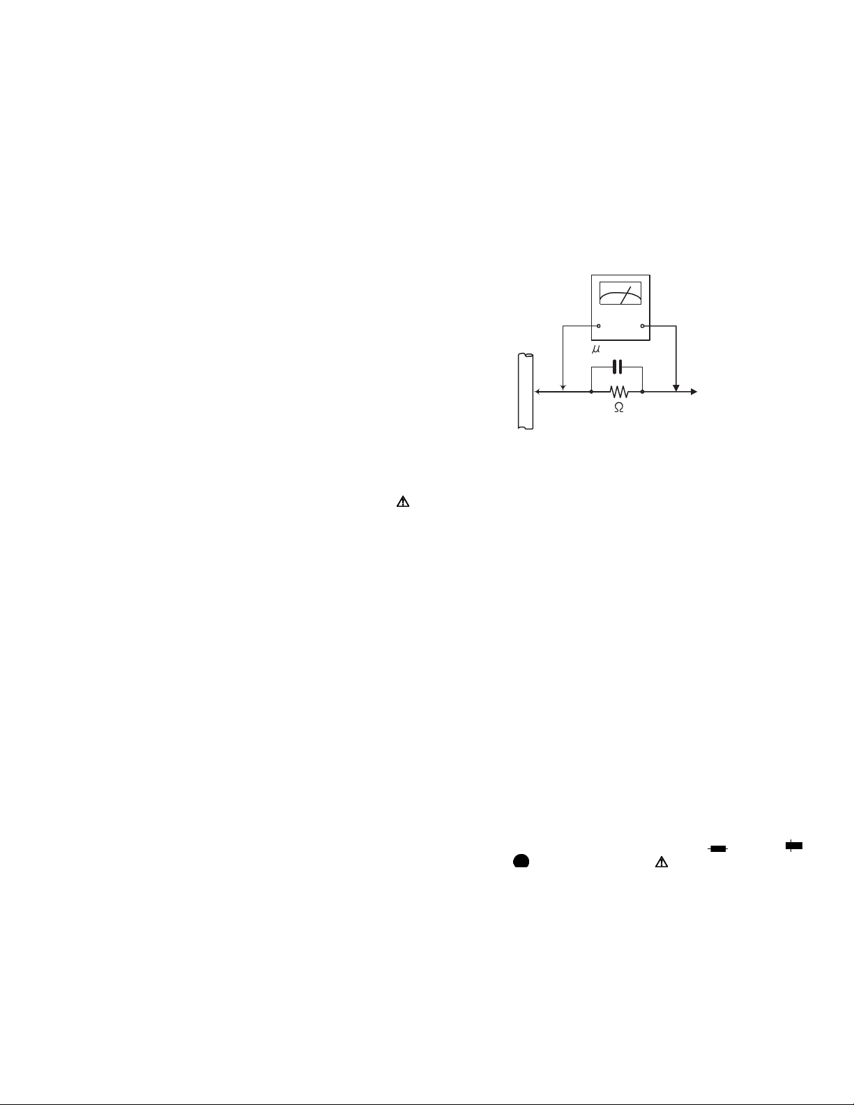
• Alternate check method
Plug the AC line cord directly into the AC outlet. Use an
AC voltmeter having, 1,000Ω per volt or more sensitivity
in the following manner. Connect a 1,500Ω 10W resistor
paralleled by a 0.15µF AC-type capacitor between an exposed metal part and a known good earth ground.
Measure the AC voltage across the resistor with the AC
voltmeter.
Move the resistor connection to each exposed metal
part, particularly any exposed metal part having a return
path to the chassis, and measure the AC voltage across
the resistor. Now, reverse the plug in the AC outlet and
repeat each measurement. Voltage measured any must
not exceed 0.75 V AC (r.m.s.). This corresponds to 0.5
mA AC (r.m.s.).
AC VOLTMETER
(Having 1000
ohms/volts,
or more sensitivity)
0.15 F AC TYPE
Place this
probe on
1500 10W
Good earth ground
1.2 Warning
(1) This equipment has been designed and manufactured to
meet international safety standards.
(2) It is the legal resp onsibility of the repairer to ensure that
these safety standards are maintained.
(3) Repairs must be made in accordance with the relevant
safety standards.
(4) It is essential that safety critical compone nts are replaced
by approved parts.
(5) If mains voltage selector is provided, check setting for local
voltage.
1.3 Caution Burrs formed during molding may be left over on some parts
of the chassis.
Therefore, pay attention to such burrs in the case of preforming repair of this system.
1.4 Critical parts for safety
In regard with component parts appearing on the silk-screen
printed side (parts side) of the PWB diagrams, the parts that are
printed over with black such as the resistor ( ), diode ( )
and ICP ( ) or identified by the " " mark nearby are critical
for safety. When replacing them, be sure to use the parts of the
same type and rating as specified by the manufacturer.
(This regulation dose not Except the J and C version)
each exposed
metal part.
(No.MB124)1-3
Page 4
1.5 Preventing static electricity
Electrostatic discharge (ESD), which occurs when static electricity stored in the body, fabric, etc. is discharged, can destroy the laser
diode in the traverse unit (optical pickup). Take care to prevent this when performing repairs.
1.5.1 Grounding to prevent damage by static electricity
Static electricity in the work area can destroy the optical pickup (laser dio de) in devices such as CD players.
Be careful to use proper grounding in the area where repairs are being performed.
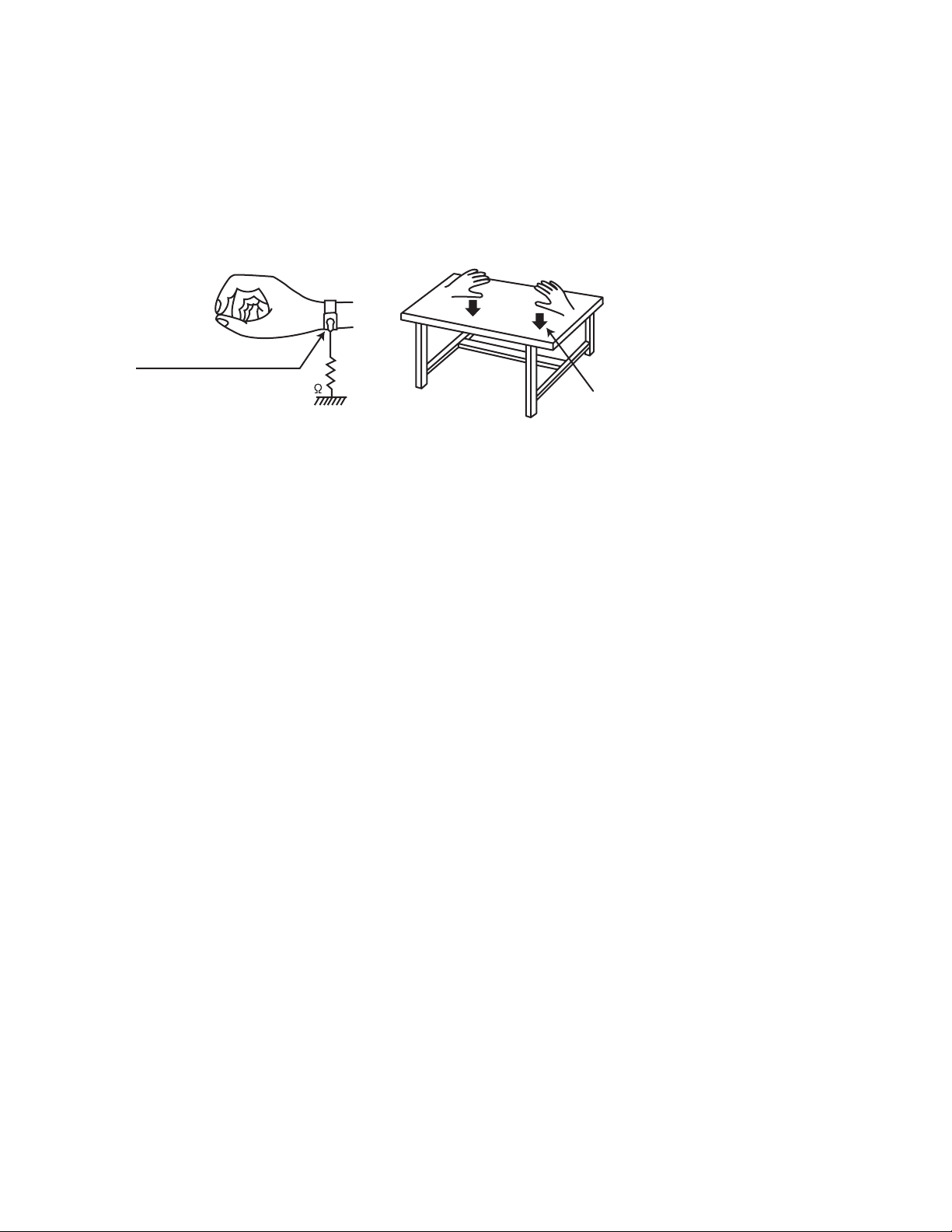
(1) Ground the workbench
Ground the workbench by laying conductive material (such as a conductive sh eet) or an iron plate over it before placing the
traverse unit (optical pickup) on it.
(2) Ground yourself
Use an anti-static wrist strap to release any static electricity built up in your body.
(caption)
Anti-static wrist strap
1M
Conductive material
(conductive sheet) or iron palate
(3) Handling the optical pickup
• In order to maintain quality during transport and before installation, both sides of the laser diode on the re placement optical
pickup are shorted. After replacement, return the shorted parts to their original condition.
(Refer to the text.)
• Do not use a tester to check the condition of the laser diode in the optical pickup. The tester's internal power source can easily
destroy the laser diode.
1.6 Handling the traverse unit (optical pickup)
(1) Do not subject the traverse unit (optical pickup) to strong shocks, as it is a sensitive, complex unit.
(2) Cut off the shorted part of the flexible cable using nippers, etc. after replacing the optical pickup. For specific details, refer to the
replacement procedure in the text. Remove the anti-static pin when replacing the traverse unit. Be careful not to take too long
a time when attaching it to the connector.
(3) Handle the flexible cable carefully as it may break when subjected to strong force.
(4) I t is not possible to adjust the semi-fixed resistor that adjusts the laser power. Do not turn it.
1-4 (No.MB124)
Page 5
1.7 Attention when pickup unit is removed
1.7.1 Attention when MD pickup unit is removed
*Please refer to "Disassembly method" in the text.
(1) Apply solder to short land section before the flexible wire is disconnected from the connector CN610
board.
(If the flexible wire is disconnected without applying solder, the MD pickup may be destroyed by static electricity.)
(2) In the assembly, be sure to remove solder from the short land section after connecting the flexible wire.
MD servo control board
MD servo control board
on the MD servo control
CN310
Short land section
Flexible wire
MD pickup
1.7.2 Attention when CD pickup unit is removed
*Please refer to "Disassembly method" in the text.
(1) Apply solder to short land section before the card wire is disconnected from the connector on the flexibl e board.
(If the card wire is disconnected without applying solder, the CD pickup may be destroyed by static electricity.)
(2) In the assembly, be sure to remove solder from the short land section after connecting the card wire.
Card wire
Short land section
CD pickup
Flexible board
(No.MB124)1-5
Page 6
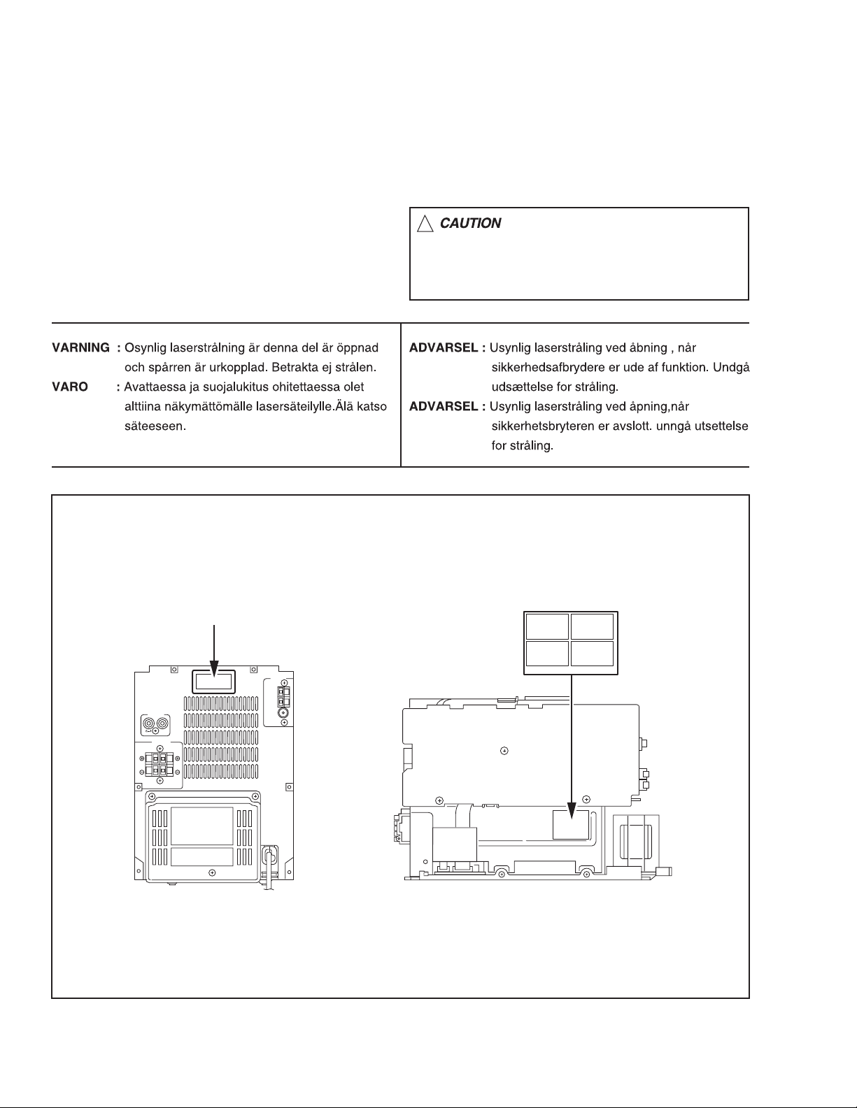
1.8 Important for laser products
1.CLASS 1 LASER PRODUCT
2.DANGER : Invisible laser radiation when open and inter
lock failed or defeated. Avoid direct exposure to beam.
3.CAUTION : There are no serviceable parts inside the
Laser Unit. Do not disassemble the Laser Unit. Replace
the complete Laser Unit if it malfunctions.
4.CAUTION : The compact disc player uses invisible laser
radiation and is equipped with safety switches which
prevent emission of radiation when the drawer is open and
the safety interlocks have failed or are de
feated. It is dangerous to defeat the safety switches.
5.CAUTION : If safety switches malfunction, the laser is able
to function.
6.CAUTION : Use of controls, adjustments or performance of
procedures other than those specified herein may result in
hazardous radiation exposure.
!
Please use enough caution not to
see the beam directly or touch it
in case of an adjustment or operation
check.
REPRODUCTION AND POSITION OF LABEL and PRINT
WARNING LABEL and PRINT
CLASS 1 LASER PRODUCT LABEL
CLASS 1
LASER PRODUCT
LASER CAUTION LABEL
E406507-
1-6 (No.MB124)
Page 7

SECTION 2
SPECIFIC SERVICE INSTRUCTIONS
This service manual does not describe SPECIFIC SERVICE INSTRUCTIONS.
(No.MB124)1-7
Page 8
SECTION 3
r
DISASSEMBLY
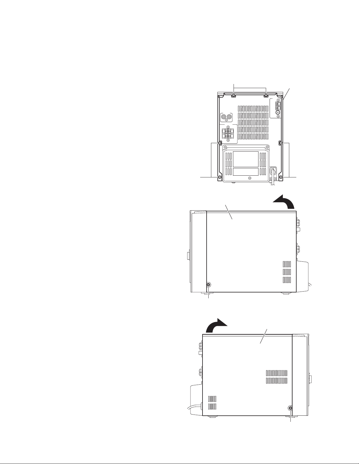
3.1 Main body section
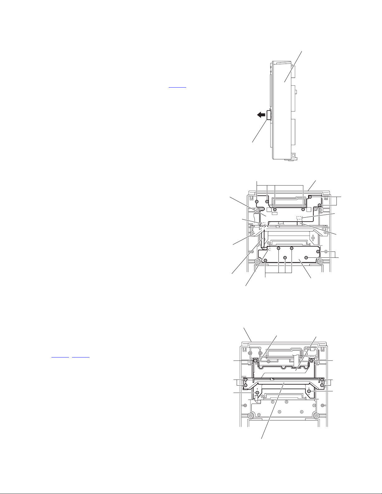
3.1.1 Removing the metal cover
(See Figs.1 to 3)
(1) From the back side of the main body, remove the six
screws A attaching the metal cover. (See Fig.1.)
(2) From the both sides of the main body, remove the two
screws B attaching the metal cover. (See Figs.2 and 3.)
(3) Remove the metal cover in the direction of the arrow while
extending the lower sections of the metal cover. (See
Figs.2 and 3.)
A
Metal cove
A
A
Fig.1
Metal cover
B
Fig.2
Metal cover
1-8 (No.MB124)
B
Fig.3
Page 9
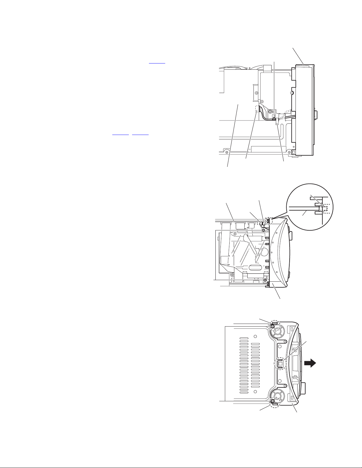
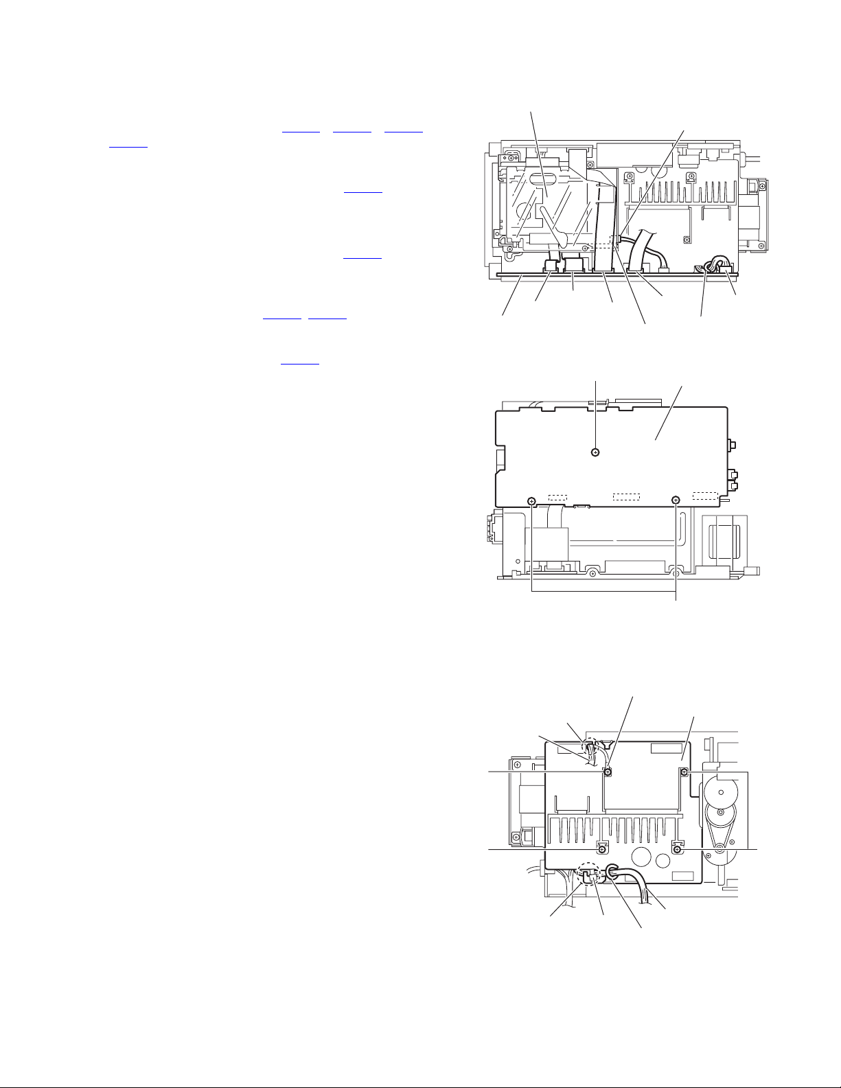
3.1.2 Removing the front panel assembly
(See Figs.4 to 6)
• Remove the metal cover.
(1) From the left side of the main body, remove the screw C
attaching the earth wire. (See Fig.4.)
(2) Disconnect the wire from the connectors CN906
power supply board. (See Fig.4.)
(3) From the top side of the main body, remove the two screws
D attaching the front panel assembly. (See Fig.5.)
(4) From the bottom side of the main body remove the two
screws E attaching the front panel assembly. (See Fig.6.)
(5) Release the two hooks a and hook b from the both and
bottom sides of the front panel assembly, and draw out the
front panel assembly in the direction of the arrow. (See
Fig.6.)
(6) From the top side of the main bo dy, disconnect the card
wires from the connectors (CN706
board. (See Fig.5.)
(7) Remove the front panel assembly from the main body.
Reference:
When attaching the front panel assembly, fit the micon board
to the notch c on the back side of the front panel assembly.
(See Fig.5.)
, CN708) on the micon
on the
CN906
Power supply board
Front panel assembly
C
Spacer
Fig.4
Micon board
D
CN706
Notch c
CN708
Micon board
Front panel assembly
Fig.5
Hook a
Hook b
E
Hook a
Front panel assembly
Fig.6
(No.MB124)1-9
Page 10
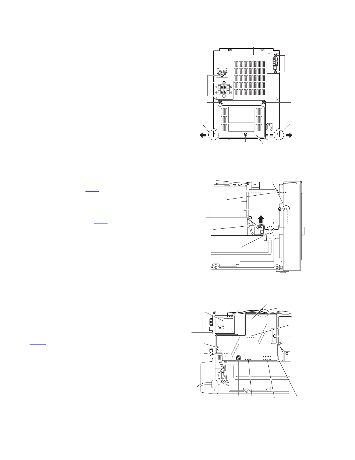
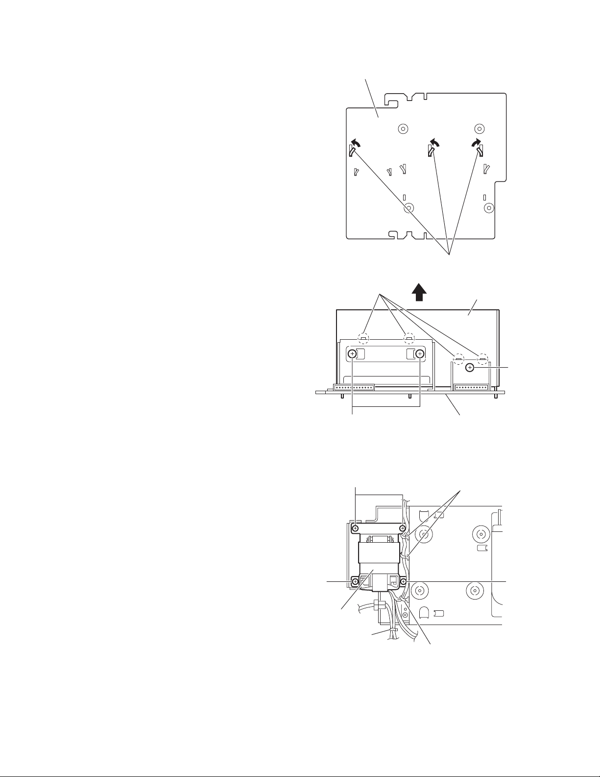
3.1.3 Removing the rear panel
r
(See Fig.7)
• Remove the metal cover.
(1) From the back side of the main body, remove the five
screws F attaching the rear panel.
(2) Remove the screw G attaching the rear cover.
(3) Remove the rear cover from the chassis wh ile extending
the sections d of the rear panel in the direction of the arrow.
Reference:
When removing the rear cover, remove the screw G and two
screws G’.
F
G'
Rear panel
F
G'
3.1.4 Removing the cassette board
(See Fig.8)
• Remove the metal cover.
(1) From the left side of the main body, disconn ect the card
wire from the connector CN32
(2) Remove the two screws H attaching the cassette board.
(3) Release the joint section e toward this side and remove the
joint section f in the direction of the arrow.
(4) From the forward side of the cassette board, disconnect
the wire from the connector CN31
3.1.5 Removing the power supply board
(See Fig.9)
• Remove the metal cover.
(1) From the left side of the main body, remove the screw J
and screw J’attaching the power supply board.
(2) Disconnect the conne ctors (CN901
supply board toward this side.
(3) From the forward side of the power supply board,
disconnect the wires from the connectors (CN902
).
CN904
Reference:
When attaching the screw J’ attach the primary protector with
it.
3.1.6 Removing the tuner
(See Fig.9)
• Remove the metal cover.
(1) From the left side of the main body, disconn ect the card
wire from the connector CN1
(2) From the back side of the main body, remove the two
screws K attaching the tuner.
Reference:
After attaching the tuner, put the card wire on the section g of
the primary protector.
on the cassette board.
.
, CN905) on the power
, CN903,
on the tuner.
d
Card wire
CN32
Cassette board
H
CN31
Tuner
K
CN903
CN904
Joint f
Card wire
G
Fig.7
Fig.8
Power supply board
CN1
J
CN905
Fig.9
Rear cover
Joint e
g
CN901
d
CN902
J'
Primary
protecto
1-10 (No.MB124)
Page 11
3.1.7 Removing the micon board
(See Figs.10 and 11)
• Remove the metal cover, front panel assembly and rear panel.
(1) From the top side of the main bo dy, disconnect the card
wires from the connectors (CN703
) on the micon board. (See Fig.10.)
CN714
(2) Disconnect the wire from the connector on the load board
of the cassette mechanism assembly. (See Fig.10.)
(3) Disconnect the wire from the connector CN701
micon board. (See Fig.10.)
Reference:
When reassembling, fix the wire with wire clamp after
connecting the wire to the connector CN701
micon board. (See Fig.10.)
(4) From the right side of the main body, remove the three
screws L attaching the micon board. (See Fig.11.)
(5) Disconnect the connectors (CN711
board toward this side. (See Fig.11.)
(6) From the forward side of the micon board, disconnect the
card wires from the connectors CN709
, CN704, CN710,
on the
on the
, CN713) on the micon
. (See Fig.11.)
Cassette mechanism assembly
CN704
Micon board
CN710
CN703
Load board
Fig.10
L
Connector
CN714
Wire clamp
Micon board
CN701
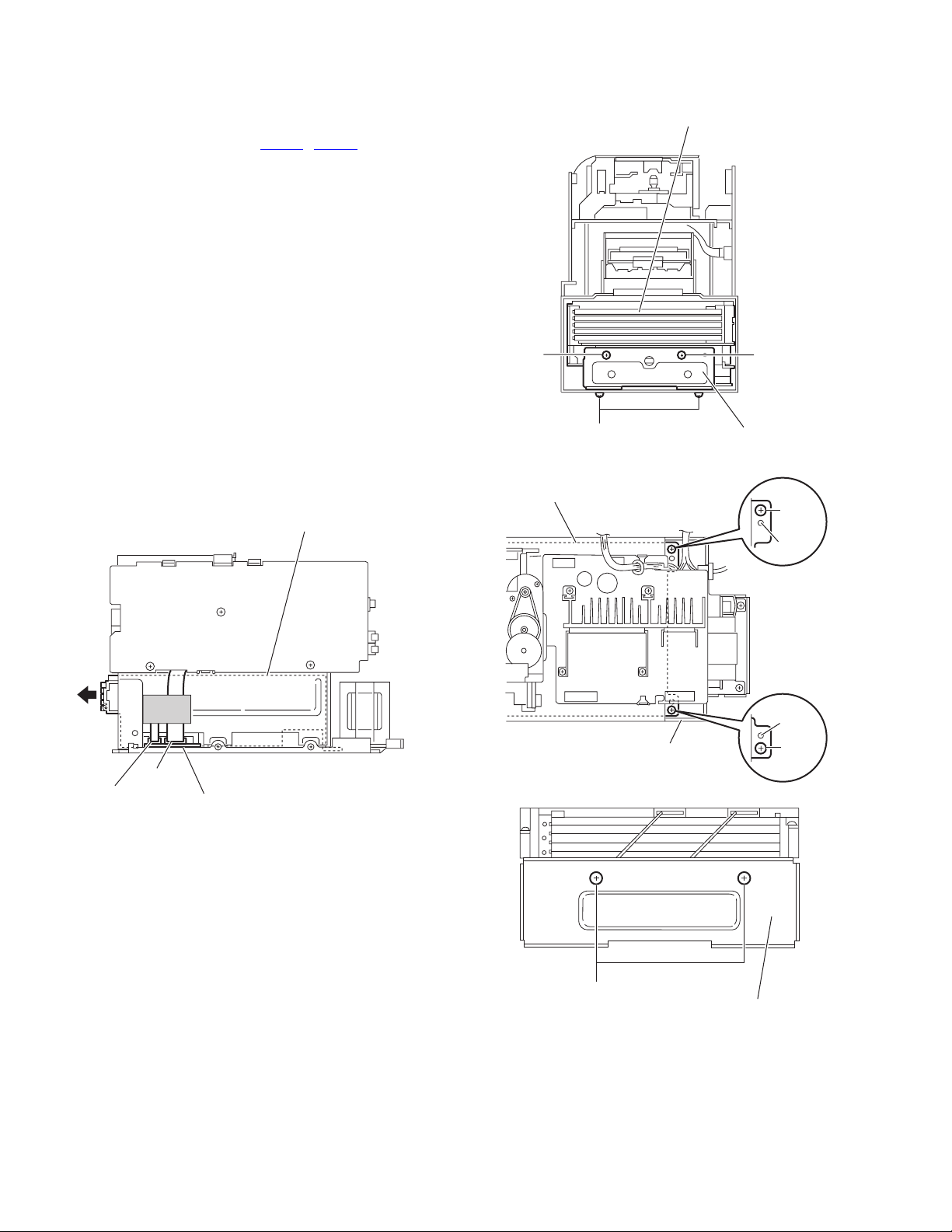
3.1.8 Removing the power amplifier board
(See Fig.12)
• Remove the metal cover, front panel assembly, rear panel,
power supply board and micon board.
(1) From the top side of the main body, remove the wire clamp
and tie band fixing the wire 1.
(2) Remove the three screws M and screw N attaching the
power amplifier board.
Reference:
• After attaching the power amplifier baord, pass the wire 1
through the section h of the power amplifier board and fix the
wire 1 with the wire clamp and tie band.
• Pass the wire 2 and earth wire through section i of the power
amplifier board.
• When attaching the screw N, attach the earth wire with it.
N
M
Wire 2
CN709
i
CN713 CN711
L
Fig.11
Earth wire
Power amplifier board
M
h
Tie band
Fig.12
Wire 1
Wire clamp
(No.MB124)1-11
Page 12
3.1.9 Removing the heat sink
(See Figs.13 and 14)
• Remove the metal cover, front panel assembly, rear panel,
power supply board, micon board and power amplifier board.
(1) From the reverse side of the power amplifier board, bend
the claw j of the heat sink in the direction of the arrow. (See
Fig.13.)
(2) From the side of the power amplifier board, remove the
three screws P attaching the heat sink.
(3) Disengage the joints k and remove the heat sink in the
direction of the arrow. (See Fig.14.)
Power amplifier board
Fig.13
Joints k
Claw j
Heat sink
3.1.10 Removing the power transformer
(See Fig.15)
• Remove the metal cover, front panel assembly, rear panel,
power supply board, micon board and power amplifier board.
(1) From the top side of the main body, remove the wire clamp
fixing the wire.
(2) Remove the tie band.
(3) Remove the four screws Q attaching the power transformer
and take out the power transformer from the main body.
P
Q
Q
Power
transformer
Tie band
P
Power amplifier board
Fig.14
Wire clamps
Q
Wire clamp
Fig.15
1-12 (No.MB124)
Page 13
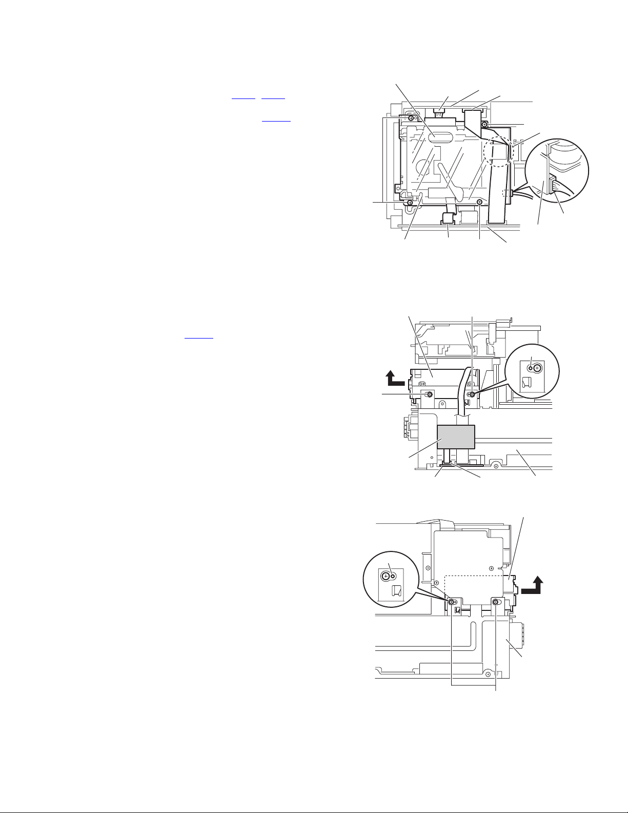
3.1.11 Removing the cassette mechanism assembly
(See Fig.16)
• Remove the metal cover and front panel assembly.
(1) From the top side of the main bod y, disconnect the wire
and card wire from the connectors (CN31
cassette board.
(2) Disconnect the card wire from the connector CN704
micon board.
(3) Disconnect the wire from the connector on the load board
of the cassette mechanism assembly.
(4) Remove the four screws R attaching the cassette
mechanism assembly, and take out the cassette
mechanism assembly from the main body.
Reference:
After reassembling, put the card wire through the section m of
the mechanism protector.
3.1.12 Removing the MD mechanism assembly
(See Figs.17 and 18.)
• Remove the metal cover, front panel assembly and micon
board.
(1) From the right side of the main body, disconne ct the card
wire from the connector CN652
board. (See Fig.17.)
Reference:
After reassembling, fix the card wire with the spacer.
(2) From the both sides of the main body, remove the four
screws S attaching the MD mechanism assembly. (See
Figs.17 and 18.)
(3) Remove the MD mechanism assembly from the bosses n
and p, and take out it in the direction of the arrow. (See
Figs.17 and 18.)
on the CD servo control
, CN32) on the
on the
Cassette mechanism assembly
CN31
R
Insulator
MD mechanism assembly
CN704
Fig.16
S
Spacer
Cassette board
CN32
R
Micon board
S
R
m
Connector
Load board
Boss n
CD servo control board
Fig.17
Boss p
Fig.18
CN652
MD mechanism assembly
Main chassis
Main chassis
S
(No.MB124)1-13
Page 14
3.1.13 Removing the CD changer mechanism assembly
(See Figs.19 to 22.)
• Remove the metal cover and front panel assembly.
(1) From the right side of the main body, disconnect the card
wires from the connectors (CN651, CN652) on the CD
servo control board. (See Fig.19.)
(2) From the front and bottom sides of the main body, remove
the two screws T and two screws U attaching the CD bracket(F). (See Fig.20.)
(3) From the top side of the main body, remove the two screws
V attaching the CD changer mechanism assembly. (See
Fig.21.)
Reference:
When attaching the CD changer mechanism assembly,
align the bosses q and r of the bottom chassis in the hole
of the CD changer mechanism assembly. (See Fig.21.)
(4) Take out the CD changer mechanism assembly in the
direction of the arrow. (See Fig.19.)
Note:
When take out the CD changer mechanism assembly,
be careful not to damage the several parts on the C D
servo control board.
(5) From the back side of the CD changer mechanism
assembly, remove the two screws W attaching the CD
bracket(R). (See Fig.22.)
CD changer mechanism assembly
CD changer mechanism assembly
T
U
Fig.20
CD changer mechanism assembly
T
CD bracket (F)
V
Boss q
CN652
CN651
CD servo control board
Fig.19
Bottom chassis
W
Boss r
V
Fig.21
CD bracket (R)
Fig.22
1-14 (No.MB124)
Page 15
3.1.14 Removing the switch board
(See Figs.23 and 24)
• Remove the metal cover and front panel assembly.
(1) From the front side the front panel assemb ly, pull out the
volume knob. (See Fig.23.)
(2) From the inside of the front panel assembly, remove the six
screws X attaching the switch board. (See Fig.24.)
(3) Take out the switch board from the front panel assembly
and disconnect the card wire from the connector CN510
the forward side. (See Fig.24.)
Front panel assembly
on
Volume knob
Fig.23
3.1.15 Removing the back light board
(See Figs.24 and 25)
• Remove the metal cover and front panel assembly.
(1) From the inside of the front panel assembly, remove the six
screws Y attaching the back light board. (See Fig.24.)
(2) Take out the back light board from the front panel assembly
and disconnect the card wires from the connectors
(CN561
Reference:
Remove the stay bracket as required. (See Fig.25.)
, CN562) on the forward side. (See Fig.24.)
Y
Back light
board
CN561
Stay bracket
Card wire
CN510
Front panel assembly
AA
Z
AA
X
Fig.24
LED lens
Front panel assembly
Y
CN562
Card
wire
X
Switch board
Lens holder
AA
Z
AA
Stay bracket
Fig.25
(No.MB124)1-15
Page 16

3.1.16 Removing the FL board
(See Figs.25 and 26)
• Remove the metal cover, front panel assembly and back light
board.
(1) From the inside of the front panel assembly, remove the
four screws Z attaching the stay bracket and take out the
stay bracket . (See Fig.25.)
(2) Remove the four screws AA attaching the lens holder and
LED lens, take out the lens holder and LED lens. (See
Fig.25.)
(3) Take out the FL board from the front panel assembly.. (See
Fig.26.)
Note:
When attaching the FL board, be careful n ot to damage the
projection s of the DI570.
FL board
Front panel assembly
3.1.17 Removing the headphone jack board
(See Fig.27)
• Remove the metal cover and front panel assembly.
(1) From the inside of the front panel assembly, remove the
screw AB attaching the headphone jack board.
(2) Take out the headphone jack board fro m the front panel
assembly.
Reference:
After attaching the headphone jack board, fix the wire with the
spacer.
Projection s
Front panel assembly
Fig.26
Fig.27
DI570
AB
Spacer
Headphone
jack board
1-16 (No.MB124)
Page 17

3.2 CD changer mechanism
r
3.2.1 Removing the tray assembly
(See Fig.1 ~ 5)
(1) Remove the two screws A from the top cover and release
the two joints a on both sides of the body.
(2) Remove the top cover with the two rods attached to the top
cover and lifter assembly respectively.
(3) Remove the open det lever on the left side of the body.
(4) Push part b of the slide (R) assembly on the right side of
the body to unlock the tray assembly. Draw out the trays to-
ward the front.
Attention:
The tray can be locked if all tray assemblies are attached.
(5) From top of the body, move the stopper tab c in th e direc-
tion of the arrow and release. Pull out the tra y assemblies
from the body.
Caution:
Remove the tray assembly from top tray 5 in order.
Attention:
When reattaching the sub tray of the tray assembly, or when
removing the CD remaining inside, refer to another section.
Top cover
Open det leve
Fig.3
c
A
a
Lifter assembly
a
Rod
Fig.1
Top cover
A
Rod
a
Tray assembly
(Tray 5)
b
Fig.4
Lifter assembly
a
Fig.2
Fig.5
(No.MB124)1-17
Page 18

3.2.2 Removing the servo control board
(See Fig.6 ~ 9)
Caution:
Solder the short-circuit point on the pickup before disconnecting the card wire extending from the pickup. If you do not follow
this instruction, the pickup may be damaged.
(1) Disconnect the card wire fro m connector CN251
wire from connector CN252
vo control board on the bottom of the body. Disconnect the
wire from joint d.
(2) Solder the short round point on the flexible board of the pick
up.
(3) Remove the four screws B and turn the servo control board
as shown in the figure.
(4) Disconnect the card wire from connector CN601
servo control board.Caution: Unsolder the short-circuit
point after reassembling.
Caution:
When reassembling, twist the wires to be connected to co nnector CN252
3.2.3 Removing the switch board
(See Fig.9)
(1) Disconnect the wires from connector CN252
on the servo control board.
(2) Remove the screw C attaching the switch board.
(3) Release the wires from the slot e of the switch board.
Caution:
When reassembling, let the wires through the slot e of the
switch board and twist them twice.
and CN253 twice.
Servo control board
, CN253 and CN602 on the ser-
and each
on the
and CN253
B
Card wire
Short round
Flexible board
Pickup
Fig.7
Card wire
CN601
CN602
d
B
Fig.6
CN253
CN252
B
CN251
Switch board
Servo control board
Fig.8
Servo control board
CN253
e
CN252
Switch board
C
Fig.9
1-18 (No.MB124)
Page 19

3.2.4 Removing the motor board
(See Fig.10 , 11)
• Prior to performing the following procedure, remove the servo
control board.
(1) Turn over the body an d remove the two screws D. Move
the CD module bkt. in the direction of the arrow to release
two joints f.
(2) Unsolder the four soldered parts on the motor of the motor
board.
Caution:
If removing the motor board with the motor, you should
remove the screws attaching the motor from top of the
body(Refer to another section).
(3) Remove the two screws E attaching the motor board.
(4) Remove the spacer fixing the motor board and tray switch
board, and disconnect connector CN2
(5) Disconnect the card wire from connector CN1
board.
Caution:
When reconnecting the card wire, let the card wire through the
slot g of the motor board and attach it to the bottom of the body
using a double tape.
on the motor board.
on the motor
f
f
CD Module
braket
DD
Fig.10
Spacer
Soldering point
CN2
CN1
g
E
E
Motor
Double
face tape
Card wire
Fig.11
(No.MB124)1-19
Page 20

3.2.5 Removing the CD tramecha assembly
(See Fig.12)
• Prior to performing the following procedure, remove the servo
control board.
(1) Turn over the body and remove the three screws F attach-
ing the tramecha.
F
F
F
CD Tramecha assembly
Fig.12
1-20 (No.MB124)
Page 21

3.2.6 Removing the pickup
(See Fig.13 , 14)
• Prior to performing the following procedure, remove the servo
control board and CD tramecha assembly.
(1) From top of the CD tramecha assembly, turn the cam gear
in the direction of the arrow to move the pickup assembly
outward.
(2) Push down the stopper h in the direction of the arrow and
pull out the shaft.
(3) Release the joint i of the pickup assembly and mecha
base.
(4) Remove the screw G attaching the CD rack. Re lease the
four tabs j at the bottom of the CD rack.
Mecha base
h
Stopper
i
Pickup assembly
Shaft
Cam gear
ShaftShaft
Stopper
Fig.13
CD lack
G
Pickup
j
j
j
Fig.14
(No.MB124)1-21
Page 22

3.2.7 Removing the side (L)/ tray switch board
(See Fig.15 ~ 17)
• Prior to performing the following procedure, remove the tray
assembly.
(1) Remove the two screws H attaching the side (L) on top of
the body.
(2) From the side of the body, remove the spacer fixing the tray
switch board and motor board. Disconnect connector CN3
on the tray switch board and detach the side (L) upward.
(3) Remove the screw J attaching the tray switch board.
(4) Push the joint tab k of the side (L) in the direction of the ar-
row and remove the tray switch board outward, then re-
lease joint l.
H
Side (L)
H
Fig.15
H
H
Side (L)
CN3
Spacer
Side (L)
Fig.16
k
1-22 (No.MB124)
Tray switch board
Fig.17
l
J
Page 23

3.2.8 Removing the side (R) assembly
(See Fig.18 ~ 22)
• Prior to performing the following procedure, remove the tray
assembly.
(1) Push and release the two tabs m of the gear cover through
the two notches inside the side (R) assembly. Remove the
gear cover outward.
(2) Remove the spring attached to p art n of the hook on the
right side of the body.
(3) From top of the body, turn the 1 gear clockwise to move the
elevator cam rearward.Move the two slots o and joint p of
the elevator cam as shown in Fig.21 and remove the elevator cam outward.
(4) Remove the three screws K and detach the side (R) up-
ward.
Caution:
When reattaching the side (R) assembly, make sure to fit the
shaft (part q) into the slot of the select lever.
Side (R) assembly
m
Fig.20
K
Side (R)
assembly
K
Side (R) assembly
K
Fig.18
q
Spring
n
Elevator cam
o
o
p
Fig.21
K
Side (R) assembly
1 gear
Gear cover
Sprihg
K
n
Fig.22
Elevator com
Fig.19
(No.MB124)1-23
Page 24

3.2.9 Removing the lifter assembly
(See Fig.23 ~ 27)
• Prior to performing the following procedure, remove the tray
assembly and side (L)/ side (R) assembly.
(1) From top of the body, turn the 1 gear clockwise to move the
lifter assembly upward as shown in Fig.24.
(2) From top of the body, turn the 2 gear clockwise to move the
hook toward the front until it stops.
(3) Move the hook stopper in the direction of the arrow while
pushing the tab r of the hook stopper to unlock it. Release
four joints s to detach from the rack holder.
Release the rod from part t.
(4) Turn the 1 gear clockwise again to move the lifter assembly
upward.
(5) Remove the lifter assembly fr om the body up ward at posi-
tion u where the four pins on the right and left sides of the
lifter assembly fit to the notches of the v.
Move the lifter assembly toward the front and release from
the hook.
2 gear
1 gear
Hook
t
s
Rod
s
s
r
s
Hook stopper
Fig.25
Lifter assembly
1 gear
u u
Hook stopper
Hook
2 gear
Fig.23
1 gear
Lifter
assembly
Lifter assembly
v
Lifter assembly
Fig.26
u
u
Hook stopper
1-24 (No.MB124)
Hook
Fig.24
v
Fig.27
Page 25

3.2.10 Removing the rack holder assembly/ sensor assembly
(See Fig.28 ~ 33)
• Prior to performing the following procedure, remove the tray
assembly, side (L)/ side (R) assembly, lifter assembly.
Attention:
If the slide gear of the body places at joint w of the rack holder
assembly, turn the 1 gear counterclockwise to move the slide
gear toward the front. Remove the rack holder assembly.
(1) Remove the three screws J attaching the rack holder as-
sembly. Release joint w from the notch.
Caution:
When reattaching the rack holder assembly, do not nip
the wire x extending from the sensor assembly.
(2) Remove the two screws M attaching the sensor assembly.
(3) Move the sensor assembly in the direction of the arrow to
release from the slot at joint y.
(4) Remove the spring attached to the bottom of the sensor as-
sembly from the boss z on the sensor slider.
(5) Remove the screw N and O attaching the sensor board and
SV resister respectively.If necessary, unsolder the sensor
board.
Caution:
When reattaching the SV resister, attach the sensor slider to
the sensor bracket and fit the lever on the bottom of the SV resister into slot a’ of the sensor slider.
Caution:
When reattaching the rack holder assembly, turn the 1 gear
clockwise to move the slide gear and slide lever inside the
body rearward.
• Let the wire extending from the sensor assembly through notch
x to the bottom of the body.
• Fit pin c’of the slide lever into hole b’ of the sensor slider on
the bottom of the sensor assembly while attaching the spring
to the boss z of the sensor slider.
• Engage joint y of the sensor assembly to the notch of the b ody.
Rack holder
assembly
Rack holder
assembly
L
w
L
1 gear
x
L
Fig.28
Rack holder
assembly
w
w
Fig.29
(No.MB124)1-25
Page 26

x
O
Soldering
SV resister
N
Sensor board
point
M
z
M
Sensor slider
y
a'
Fig.30
b'
Sensor assembly
Spring
Spring
a'
Slide gear
Sensor braket
Sensor slider
Fig.32
M
Sensor assembly
M
y
b'
z
z
Fig.31
c'
Spring
Fig.33
Slide lever
1-26 (No.MB124)
Page 27

3.2.11 Removing the motor
r
(See Fig.34 ,35)
• Prior to performing the following procedure, remove the servo
control board and top cover.
Attention:
You need not to remove the tray assembly, and in such case,
move it.
(1) Remove the two belts on top of the body.
(2) Remove the four screws N attaching the motor.
(3) Remove the motor board from the bottom of the body.
(Refer to the section “Removing the motor board”.)
Attention:
When removing the motor board with the motor, you need not
to unsolder four soldered parts.
Caution:
When reattaching the motor, turn the side where the label
should be put to the front side.
Motor
Moto
NN
Belt
Fig.34
Label
Belt
Fig.35
(No.MB124)1-27
Page 28

3.2.12 Taking out the CD in play mode
r
(See Fig.36 ~ 39)
Attention:
Refer to “Removing the tray assembly”.
(1) Remove the top cover upward.
(2) Unlock the tray assembly and draw out the tray assembly
toward the front.
(3) From top of the body, turn the 1 gear clockwise to move the
lifter assembly upward.
(4) From top of the body, turn the 2 gear clockwise to move the
sub tray remaining inside the lifter assembly toward the
front, then pull out.
(5) Take out the CD on the sub tray.
(6) After clearing away the CD, insert the sub tray into the main
tray.
Caution:
When reattaching the sub tray, move the tray stopper on
the bottom of the main tray in the direction of the arrow
to lock the sub tray certainly.
(7) Push the tray assembly toward the body and reattach.
Tray assembly
Tray assembly
Tray stopper
Sub tray
Fig.37
Main tray
2 gear
1 gear
Sub tray
Sub tray
Fig.38
Fig.36
Tray stoppe
1-28 (No.MB124)
Fig.39
Page 29

3.3 MD mechanism section
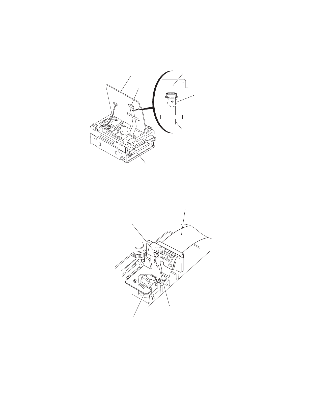
3.3.1 Removing the MD servo control board
(See Figs.1 and 2)
Caution:
Be sure to solder the short land section on the flexible wire
before disconnecting the flexible wire from the connector
on the MD servo control board.
CN310
If the flexible wire is disconnected without attaching solder, the
pickup may be destroyed by static electricity. (See Fig.2.)
(1) From the bottom side of the main body, disconnect the card
wire from the connector CN408
board. (See Fig.1)
(2) Disconnect the flexible wire from the connector CN407
the MD servo control board. (See Fig.1.)
(3) Remove the wires from the soldered section a on the MD
servo control board. (See Fig.1.)
(4) Remove the two screws A attaching the MD servo control
board. (See Fig.1.)
(5) Move the MD servo control board in th e direction of the
arrow and remove it from the joints b of the single frame.
(See Fig.1.)
(6) From the inside of th e main body, solder the short land
section on the flexible wire. (See Fig.2.)
(7) From the reverse side of the MD servo control board,
disconnect the flexible wire from the connector CN310
remove the MD servo control board. (See Fig.2.)
Caution:
When attaching the MD servo control board, remove the
solders from the short land section after connecting the flexible
wire to the connector CN310
(See Fig.2.)
on the MD servo control
on the MD servo control board.
on
and
MD servo control board
Soldered section a
Wires
(Bottom side)
Joint b
Single frame
Fig.1
MD servo control board
AA
Card wire
CN408
CN407
Flexible wire
Joint b
MD servo control board
CN310
Pickup
Fig.2
Short land
section
Flexible wire
(No.MB124)1-29
Page 30

3.3.2 Removing the mechanism cover
r
(See Fig.3.)
(1) From the both sides of the main body, remove the four
screws B attaching the mechanism cover.
(2) Move the mechanism cover toward the front to disengage
the front hook of the mechanism cover from the internal
loading assembly (joint c). Then remove the mechanism
cover in an upward direction.
3.3.3 Removing the head lifter
(See Figs.4 to 6)
(1) Remove the head lifter spri ng from the hook of the main
body.
Reference:
Remove the head lifter spring from the head lifter as
required.
(2) Move the head lifter in the direction of the arrow, disengage
the joints d and e.
Joint c
Hook
Joint c
Head lifter
B
Mechanism cover
B
Fig.3
Joint d
Head lifter
Head lifter
Fig.4
Head lifte
spring
Joint e
Fig.5
1-30 (No.MB124)
Head lifter spring
Fig.6
Page 31

3.3.4 Removing the MD head
(See Figs.7 and 8)
• Remove the MD servo control board.
(1) From the bottom side of th e main body, remove the wire
from the H.wire holder 1. (See Fig.7.)
(2) From the top side of the main body, remove the screw C
attaching the MD head. (See Fig.8.)
Note:
• When attaching the wire, fix it to the H.wire holder 1 on the
bottom side of the pick up. (See Fig.7.)
• After attaching the wire, confirm that the rest switch is
pressed by the pickup.
Rest switch
Pickup
Wire
H.wire holder 1
Fig.7
MD head
C
Fig.8
(No.MB124)1-31
Page 32

3.3.5 Removing the loading assembly
(See Figs.9 and 10)
Reference:
The loading assembly, traverse mechanism assembly and
single frame will be removable after removing the loading
assembly from the main body.
• Remove the MD servo control board, mechanism cover, head
lifter and MD head.
(1) From the top side of the main body, remove the three
screws D attaching the loading assembly.
(2) Move the loading assembly forward to diseng age it from
the traverse mechanism assembly (joint f) and then
remove the loading assembly in an upward direction.
(3) Remove the traverse mechanism assembly from the single
frame.
Loading assembly
D
D
Joint f
D
Fig.9
Loading assembly
Traverse mechanism
assembly
1-32 (No.MB124)
Single frame
Fig.10
Page 33

3.3.6 Removing the slide base L and slide base R
(See Fig.11)
(1) From the top side of the loading assembly, remove the two
screws E attaching the slide base L and slide base R.
(2) Remove the slide base L outward. (Release it from the
joints g.)
(3) Remove the slide base R outward.
3.3.7 Removing the loading mechanism assembly
(See Fig.12)
(1) Remove the loading mechanism assembly upward to
release the four pins from the both sides of the loading
mechanism base while paying attention to the section h of
the loading mechanism base.
Slide base R
Slide base L
Pin
Joint g
Joint g
Fig.11
E
E
h
Pin
Pin
Loading mechanism assembly
Fig.12
Pin
Loading mechanism base
(No.MB124)1-33
Page 34

3.3.8 Removing the loading motor
H
r
(See Figs.13 and 14)
(1) Remove the wire from the w ire holder and disconnect the
wire from the connector CN612 on the MD cam switch
board. (See Fig.13.)
(2) Remove the screw F attaching the loading motor assembly
and disengage the joint i. (See Fig.13.)
(3) Remove the belt from th e loading motor assembly. (See
Fig.14.)
(4) Remove the two screws G attaching the loading motor.
(See Fig.14.)
3.3.9 Removing the cam gear and MD cam switch board
(See Fig.13)
(1) Remove the slit washer attaching the cam gear and pull out
the cam gear.
(2) Remove the wire from the w ire holder and disconnect the
wire from the connector CN612
board.
(3) Remove the two screws H attaching the MD cam switch
board, and remove the MD cam switch board.
on the MD cam switch
Loading motor assembly
Wire
Wire holder
Joint i
F
CN612
Fig.13
Loading motor
MD cam switch board
H
Slit washe
H
Cam gear
G
Belt
Fig.14
1-34 (No.MB124)
Page 35

3.3.10 Removing the cartridge holder assembly
(See Figs.15 and 16)
(1) From the top side of the loading assembly, remove the two
screws J attaching the slide bar and cartridge holder
assembly.
Slide bar
Cartridge holder assembly
3.3.11 Removing the slide bar and eject bar
(See Figs.15 and 16)
• Remove the cartridge holder assembly.
(1) Remove the slide bar in an upward direction.
(2) Move the eject bar outward until stops as shown in Fig.15.
Push the claw j on the bottom side of the main body and
remove the eject bar from the chassis.
J
J
Eject bar
Eject bar
Claw j
Fig.15
J
Slide bar
Boss n
Eject bar
UD base
Cartridge holder assembly
Fig.16
(No.MB124)1-35
Page 36

3.3.12 Removing the insulators
(See Fig.17)
(1) Remove the four insulators from the notches of the
traverse mechanism chassis.
Insulators
3.3.13 Removing the pickup unit
(See Fig.18)
(1) From the bottom side of the traverse mechanism
assembly, remove the screw K attaching the shaft holder
F.
(2) Move the guide shaft i n the direction of the arrow 1 and
remove it from the shaft holder R.
(3) Move the guide shaft side of the pickup unit and disengage
the joint k with the pickup guide. Then remove the pickup
unit with the guide shaft in the direction of the arrow 2.
3.3.14 Removing the pickup
(See Fig.19)
(1) Pull out the guide shaft from the pickup.
(2) Remove the two screws L attaching the rack spring to the
pickup.
Caution:
Be sure to solder the short land section on the flexible wire
before disconnecting the flexible wire from the pickup.
If the flexible wire is disconnected without attaching solder, the
pickup may be destroyed by static electricity. (See Fig.2.)
Insulators
Traverse mechanism assembly
Pickup unit
Shaft holder F
Fig.17
Joint k
2
K
Fig.18
L
Traverse mechanism chassis
Pickup guide
1
Guide shaft
Shaft holder R
Rack spring
Pickup
1-36 (No.MB124)
Guide shaft
Fig.19
Page 37

3.3.15 Removing the feed motor assembly
(See Figs.20 and 21)
Reference:
Remove the pickup unit as required.
(1) Remove the wires (White/Black) from the soldered section
k on the traverse mechanism board.
(2) Remove the two screws M attaching the feed motor
assembly. (See Fig.20.)
(3) Remove the two screws P attaching the feed motor to the
feed motor bracket. (See Fig.21.)
3.3.16 Removing the traverse mechanism board
(See Fig.20)
• Remove the feed motor assembly.
(1) Remove the wires (Red/Black) from the soldered section m
on the traverse mechanism board.
(2) Remove the screw N attaching the traverse mechanism
board.
Traverse mechanism board
Soldered section m
N
Soldered
section k
Feed motor
assembly
M
Fig.20
Feed motor
Pickup
Feed motor bracket
P
Fig.21
(No.MB124)1-37
Page 38

3.3.17 Reattaching the loading assembly
r
(1) Reattach the eject bar to the UD base. (See Figs.16 and
22.)
(2) Reattach the slide bar to the loading mechanism chassis
while fitting the boss n of the slide bar to the groove of the
eject bar. (See Fig.16.)
(3) Move the slide bar and eject bar in the direction of the
arrow as shown in Fig.22 and reattach the cartridge holder
assembly using the two screws J. (See Figs.22 and 23.)
Note:
Make sure the pin p of the eject lever is fitted to the
groove q of the eject bar at the bottom side of the loading
mechanism chassis after moving the eject lever and
loading slider of the cartridge holder assembly in the
direction of the arrow as shown in Fig.23.
(4) Reattach the wire holder to the UD base while enga ging
the hook s of the UD base to the slot r of the wire holder.
(At the same time, the boss on the reverse side of the wire
holder is fitted to the round hole of the UD base.) (See
Fig.22.)
(5) Reattach the MD cam switch board using the two screws
H. (See Fig.22.)
(6) Turn the cam switch to align the boss to the triangle mark
on the MD cam switch board. (See Fig.24.)
(7) Reattach the cam gear using a slit washer while fitting the
hole of the cam gear to the boss of the cam switch. (See
Fig.24.)
Note:
When reattaching the cam gear, the boss of the cam
switch should be fitted to the hole of the cam gear, and
the triangle mark of the cam gear should be aligned to
the hole (section r) of the eject bar as shown in Fig.24.
(8) Reattach the loading motor assembly using the screw F.
(See Fig.24.)
(9) Connect the wire of the loading motor to the connector
on the MD cam switch board.
CN612
(10) Hang the wire to the hook t of the UD base and fix it with
the wire holder.
(11) Reattach the UD base while enga ging the fou r pins on the
both sides of the UD base to the notches of the loading
mechanism base and placing the edge u of the cartridge
holder assembly under the hook h of the loading
mechanism base. (See Fig.25.)
(12) Reattach the slide base R while fitting the two pins on
another side of the UD base to the slots of the slide base
R. (See Figs.26 and 27.)
Note:
Fit the section v of the slide base R to the section w on
the inward side of the cam gear rib.
(13) Reattach the slide base L on the slide base R while fitting
the two pins on another side of the UD base to the slots of
the slide base L. Make sure the two slots of the slide base
L are fitted to the two joints g and tighten the two screws E.
(See Figs.26 and 28.)
Reference:
To expedite the work, lift the UD base slightly when fitting each
pin to the notches.
Slide bar
J
J
Groove q
(Bottom side)
Boss n
Groove q
Eject bar
UD base
Wire holder
MD cam switch board
r
s
UD base
Fig.22
Cartridge holder assembly
Loading slider
Fig.23
H
H
Eject leve
Pin p
1-38 (No.MB124)
Page 39

Triangle mark
Boss
Pins
UD base
u
Loading motor assembly
CN612
Hook t
Wire
F
Wire holder
Cam switch
MD cam
switch board
MD cam
switch board
Slit washer
Cam gear
u
Pin
h
UD base
Pins
Loading mechanism base
Fig.25
Slide base R
v
Pin
w
Pin
Pin
Fig.26
E
E
Slide base L
UD base
Eject bar
r
Fig.24
Eject bar
Cam gear
(Triangle mark)
v
Slide base R
Slide base R
Fig.27
Cam gear
g
Slide base L
w
E
Fig.28
g
(No.MB124)1-39
Page 40

3.4 Cassette mechanism section
r
CAUTION:
Prior to performing the following procedures, turn the mode
gear in the direction of the arrow to move each section to the
eject position.
3.4.1 Removing the side bracket (L) and (R) / load board
(See Fig.1 to 4)
(1) Remove the E-washer attaching the load arm on the right
side of the body.
(2) Turn the load arm in the direction of the arrow to relea se
from the cassette hook at the joint a.
(3) Remove the spring (1) attaching the trig lever.
(4) Move the trig lever in the direction of the arrow and release
it from the two holes b.
(5) Remove the screw A attaching the load board on the right
side of the body and unsolder the wire extending from the
sub motor.
(6) After removing the belt from the sub motor, remove the two
screws B attaching the sub motor.
REFERENCE:
The side bracket unit (R) can be removed even if the load
board is attached. In such case, make sure to unsolder
the wire extending from the sub motor.
(7) Remove the spring (2 ) and the holder collar on the right
side of the body.
(8) Remove the four screws C attaching the side bracket unit
(R) in the direction of the arrow.
(9) Remove the two screws D attaching the side bracket (L) in
the direction of the arrow.
D
A
Loard board
D
B
B
Sub moto
Belt
Soldering
Fig.3
Cassette hanger assembly
C
Joint a
Loard arm
Fig.1
Slide bracket
E washer
Loard arm
Hole b
Hole b
C
C
C
Holder collar
Spring (2)
Side bracket unit (R)
Fig.4
1-40 (No.MB124)
Fig.2
Spring (1)
Page 41

3.4.2 Removing the cassette hanger assembly / cassette holder
r
(See Fig.5)
• Prior to performing the following procedure, remove the side
bracket (L) and (R).
(1) Remove the slit washer attaching the cassette hanger as-
sembly and pull out the pin.
(2) Move the cassette hanger assembly in the directi on of the
arrow to release the boss of the joint c on the left rear side
and detach the cassette hanger assembly upward.
REFERENCE:
The cassette hanger assembly is detached with the cassette holder.
3.4.3 Removing the pinch roller (F) and (R)
(See Fig.6 to 8)
• Prior to performing the following procedure, remove the side
bracket (L), (R), cassette hanger assembly / cassette holder.
(1) Release the tab d in the direction of the arrow and pull out
the pinch roller upward.
REFERENCE:
The above method is for removing the pinch roller (F)
and (R).
Cassette hanger assembly
Cassette holder
Pinch roller (F)
Pin
Slit washe
Fig.5
Pinch roller (R)
Fig.6
Pinch roller (F)
d
Ta b
Fig.7
Pinch roller (R)
Tab d
Fig.8
(No.MB124)1-41
Page 42

3.4.4 Removing the head assembly / head board
r
(See Fig.9 and 10)
• Prior to performing the following procedure, remove the side
bracket (L), (R), cassette hanger assembly / cassette holder.
(1) Remove the spring on the lower side of the head assembly.
(2) Remove the two screws E and remove the head assembly
upward.
(3) Remove the screw F attaching the head board. Unsolder
the flexible wire extending from the head assembly if necessary.
E
Fig.9
Head assembly
E
3.4.5 Removing the flywheel assembly (F) and (R)
(See Fig.11 and 12)
• Prior to performing the following procedure, remove the side
bracket (L), (R), cassette hanger assembly / cassette holder.
(1) Remove the belt and sub belt on the bottom of the bod y .
(2) Remove the polywasher from the flywheel (F) and (R) on
top of the body.
(3) Pull out the flywheel (F) and (R).
Head board
Sub belt
Flywheel assembly(R)
Soldering
F
Fig.10
Belt
Flywheel assembly(F)
Fig.11
1-42 (No.MB124)
Polywasher
Fig.12
Polywashe
Page 43

SECTION 4
f
ADJUSTMENT
4.1 Jigs and test instruments
• Laser power meter
• Laser power meter sensor (disk type)
• Premastered disk
• Recordable disk
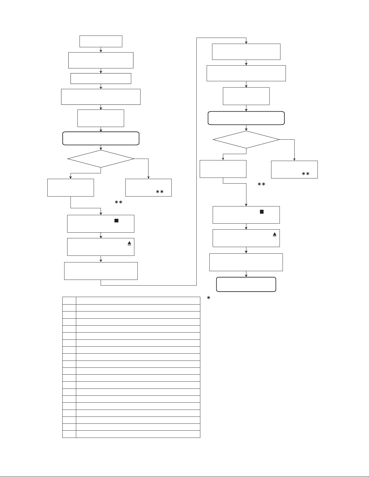
4.3 Adjustment and check method
(1) MD section
a) Setup of the TEST MODE 1
While pressing both the [UP ] key
and [STANDBY/ON] key, insert the
AC power cord in an outlet.
FL indication
TEST MODE 1
Press the [MD EJECT] key on
the main unit.
MD will be ejected i
it has already been
inserted in the unit.
4.2 Adjustment and check items
(1) MD section
a) Setup of the TEST MODE 1
b) Adjustment of the stray light
c) Initialization of the EEPROM
d) Setup of the laser power
e) Adjustment of the disk
f) Cancel of the TEST MODE
(2) Write sequence of the corrected program (ROM correc-
tion)
(3) System test mode (FL all lighting-up ch eck)
c) Initialization of the EEPROM
Note:
• When EEPROM is initialized, all data is deleted
and any adjustment will be disabled. Give the
most careful consideration to performing this operation.
• This operation should be executed only when an
EEPROM is replaced.
• The setting of the TEST MODE 1 should be completed for performing the initialization. Carry out
the following operations with a remote controller.
Press the [PLAY MODE] key
on the remote controller.
FL indication
TEST MODE 1
Setup is complete.
b) Adjustment of the stray light
(After setup of the TEST MODE 1, proceed to the following operations with th remote controller.)
Press the [MD PLAY] key on
the remote controller .
FL indication
OK TUNING
Press the [STOP ] key on
the remote controller.
FL indication
TEST MODE 1
FL indication
TEST MODE 1
Setup is complete.
Setup is complete.
(No.MB124)1-43
Page 44

d) Setup of the laser power
TEST MODE 1
Insert the laser power
meter sensor.
Press the [2] key on
the remote controller.
Press the [MD EJECT ]
key on the main unit.
Insert the laser power
meter sensor again.
Increase the laser
power with the
[UP ] key on the
main unit.
Decrease the laser
power with the
[DOWN ] key on
the main unit.
Adjust the power to be 0.68 mW or
more. If the value exceeds 0.68 mW,
approximate it to 0.68 mW as
accurately as possible.
Press the [STOP ] key
on the remote controller.
FL indication
TEST MODE 1
MD mechanism starts
its operation.
A laser power meter
sensor is ejected.
Insert the laser power
meter sensor.
Press the [4] key on
the remote controller.
Press the [MD EJECT ]
key on the main unit.
Insert the laser power
meter sensor again.
Increase the laser
power with the
[UP ] key on the
main unit.
MD mechanism starts
its operation.
A laser power meter
sensor is ejected.
Decrease the laser
power with the
[DOWN ] key on
the main unit.
Press the [MD EJECT ]
key on the main unit.
Playback laser power
adjustment is complete.
A laser power meter
sensor is ejected.
Adjust the power to be 6.23 mW or
more. If the value exceeds 6.23 mW,
approximate it to 6.23 mW as
accurately as possible.
Press the [STOP ] key
on the remote controller.
FL indication
TEST MODE 1
Press the [MD EJECT ]
key on the main unit.
A laser power meter
sensor is ejected.
Record laser power
adjustment is complete.
1-44 (No.MB124)
Page 45
e) Adjustment of the disk
TEST MODE 1
Insert the
premastered
disk for the adjustment
Reading of TOC ends.
Insert the
for the adjustment.
recordable disk
.
Press the [MD PLAY/PAUSE]
key on the remote controller.
Press the [MD PLAY/PAUSE]
key on the remote controller.
FL indication
ON TUNING
Automatic adjustment starts.
Adjustment OK?
NO
YES
FL indication
OK TUNING
FL indication
NG ERR:
: Refer to the NG judgment
code table.
Press the [STOP ] key
on the remote controller.
Press the [MD EJECT ]
key on the main unit.
The
premastered
the adjustment
Code
00 Automatic adjustment is incomplete.
01 Rest switch detection
02 Focus-on
03 EF balance, tracking offset adjustment (Pit area)
04 ABCD level (I-V resistance) adjustment (Pit area)
05 Focus servo AGC (Pit area)
06 Tracking servo AGC (Pit area)
07 Focus bias adjustment (Pit area)
08 EF balance, tracking offset adjustment (GRV area)
09 ABCD level (I-V resistance) adjustment (GRV area)
0A Focus servo AGC (GRV area)
0B Tracking servo AGC (GRV area)
0C Focus bias adjustment (GRV area)
0D Room temperature measurement
0E Write in EEPROM
10 AGC data read time out (Focus, TRK, SLED)
20 Spindle lock (Pit area)
30 Write in EEPROM
FF
Automatic adjustment is complete.
f) Cancel of the test mode
Press the [STANDBY/ON] and cut off the power.
disk for
is ejected.
NG Judgment Code Table
NG item in adjustment
FL indication
ON TUNING
Automatic adjustment starts.
Adjustment OK?
NO
YES
FL indication
OK TUNING
FL indication
NG ERR:
: Refer to the NG judgment
code table.
Press the [STOP ] key
on the remote controller.
Press the [MD EJECT ]
key on the main unit.
The
recordable disk for the
adjustment
is ejected.
Automatic adjustment
ends.
When a wrong setting is performed for the
disc type, switch the power off and on and
start the setting procedure again.
(No.MB124)1-45
Page 46

4.4 4. Write sequence of the corrected program (ROM correction)
• The adjustment of the MD section should be completed before performing this operation.
• This operation should be executed only when an EEPROM is replaced.
• Corrected program is stored in the EEPROM.
If the initialization of the EEPROM is performed, be sure to perform this operation.
Press the [STANDBY/ON] key,
turn on the power.
Press the [MD EJECT ]
key on the main unit.
FL indication
HELLO
The
disk
Insert the ROM correction disk
[S6M-2M/-11M ver.4 (2003/01/27)]
in the MO slot.
Press the [STANDBY/ON] key,
turn off the power.
ROM correction
is ejected.
FL indication
TOC READING
FL indication
EJECT
4.5 5. System test mode (FL all lighting-up check)
While pressing both the [ sound] key
and [STANDBY/ON] key, insert the
AC power cord in an outlet.
FL indication
All of the FL displays light up.
By pressing the [STANDBY/ON] key
on the main unit, the initial display
screen is resumed.
By pulling out the AC power cord of
the main unit, the test mode will be
canceled.
Writing has completed.
In the adjustment mode a 1-second real-time
increment sets the clock to gain 1 minute.
1-46 (No.MB124)
Page 47

SECTION 5
TROUBLESHOOTING
5.1 Maintenance of laser pickup (CD)
1. Cleaning the pickup lens
(1) Before you replace the pick up, please try to clean the
pickup lens.
(2) When cleaning the pickup lens with a alcoholsoaked
cotton swab.
2. Confirm the life of a laser diode
When the life of the laser diode has expired, the following
symptoms will appear.
(1) The level of RF output (EFM output, ampli tude o f eye
pattern) will below.
(2) The drive current required for light emitting oflaser diode
will be increased.
Is the level of
RFOUT under
NO
Replace it.
0.9V 0.22Vp-p?
YES
O.K
3. Semi-fixed resistor on the APC board
The semi-fixed resistor on the APC board which is attached to
the pickup is used to adjust the laser power. Since this
adjustment should be performed to match the characteristics
of the whole optical block, do not touch the semi-fixed resistor.
If the laser power is lower than the specified value, the laser
diode is almost worn out, and the laser pickup should be
replaced.
If the semi-fixed resistor would be adjusted when the pickup
operates normally, the laser pickup may be damaged due to
excessive current.
5.2 Replacement of laser pickup (CD)
Turn off the power switch and disconnect the
power cord from a AC outlet.
Replace the pickup. (Refer to "Removing the pickup"
on the previous page)
Insert the power cord in the AC outlet, and turn the
power on. At this time, check that the laser emits for
about 3 seconds and the objective lens moves up
and down.
Note: Do not observe the laser beam directly.
Play a disc.
Check the waveform of the eye-pattern
at IC601 pin5.
Completion of changing the pickup.
(No.MB124)1-47
Page 48
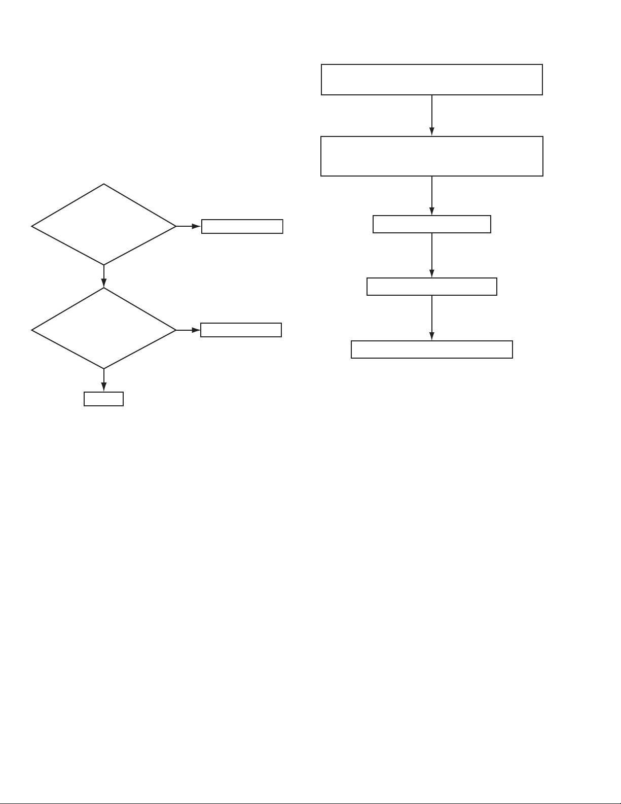
5.3 Maintenance of laser pickup (MD)
1. Confirm the life of a laser diode
When the life of the laser diode has expired, the following
symptoms will appear.
(1) Recording will become impossible.
(2) The RF output (EFM output, amplitude of eye pattern)
will become lower.
(3) The drive current required for light emitting of laser diode
will be increased.
2. Confirm the service life according to the following flow
chart.
Is the
recording power
(5.8mV) output with the
laser power under
test mode?
YES
NO
Change the pickup
5.4 Replacement of laser pickup (MD)
Change the pickup by referring to "Removing
the pickup" in the Disassembly method.
Set the pickup to "TEST MODE" according
to the procedures described in the Adjustment
method.
Adjust the laser power.
Perform a disc adjustment.
Is the drive current
of laser diode
120mA or less?
YES
OK.
3. Method of measuring the drive current of laser diode
When the voltage measured at R337(both end) on the MD
servo control board (ENX-0223) have become 120mV or over,
the service life of the laser diode is judged to have been
exhausted.
NO
Change the pickup
Completion of changing the pickup.
1-48 (No.MB124)
Page 49

(No.MB124)1-49
Page 50

VICTOR COMPANY OF JAPAN, LIMITED
AV & MULTIMEDIA COMPANY AUDIO/VIDEO SYSTEMS CATEGORY 10-1,1chome,Ohwatari-machi,Maebashi-city,371-8543,Japan
(No.MB124)
Printed in Japan
WPC
 Loading...