

Page 1
MB330200410
SERVICE MANUAL
MICRO COMPONENT SYSTEM
UX-HB4
Area suffix
B ------------------------------ U.K.
CA-UXHB4 SP-UXHB4SP-UXHB4
TABLE OF CONTENTS
1 PRECAUTION. . . . . . . . . . . . . . . . . . . . . . . . . . . . . . . . . . . . . . . . . . . . . . . . . . . . . . . . . . . . . . . . . . . . . . . . . 1-3
2 SPECIFIC SERVICE INSTRUCTIONS . . . . . . . . . . . . . . . . . . . . . . . . . . . . . . . . . . . . . . . . . . . . . . . . . . . . . . 1-7
3 DISASSEMBLY . . . . . . . . . . . . . . . . . . . . . . . . . . . . . . . . . . . . . . . . . . . . . . . . . . . . . . . . . . . . . . . . . . . . . . . 1-8
4 ADJUSTMENT . . . . . . . . . . . . . . . . . . . . . . . . . . . . . . . . . . . . . . . . . . . . . . . . . . . . . . . . . . . . . . . . . . . . . . . 1-20
5 TROUBLESHOOTING . . . . . . . . . . . . . . . . . . . . . . . . . . . . . . . . . . . . . . . . . . . . . . . . . . . . . . . . . . . . . . . . . 1-23
COPYRIGHT © 2004 Victor Company of Japan, Limited
No.MB330
2004/10
Page 2

SPECIFICATION
Amplifier Section Output Power 15 W per channel, min. RMS, driven into 4 Ω at 1 kHz with no more
than 10% total harmonic distortion. (IEC268-3)
Audio input sensitivity/Impedance (at 1 kHz) AUX:500 mV/50 kΩ
Speakers Impedance 4 Ω - 16 Ω
Tuner DAB tuning range Band lll 174.928 MHz - 239.200 MHz
FM tuning range 87.50 MHz - 108.00 MHz
AM (MW) tuning range 522 kHz - 1 629 kHz
CD player Dynamic range 85 dB
Signal-to-noise ratio 85 dB
Wow and flutter Immeasurable
Cassette deck Frequency response Normal (type I):100 Hz-10 000 Hz
Wow and flutter 0.35% (WRMS)
General Power requirement AC 230 V , 50 Hz
Power consumption 40 W (at operation) 2 W (on standby)
Dimensions (W/H/D) (approx.) 152 mm × 233 mm × 297 mm
Mass (approx.) 4.0 kg
Speaker Section Type Full range, bass-reflex type
Speakers 10 cm cone × 1
Power handling capacity 15 W
Impedance 4 Ω
Frequency range 100 Hz-15 kHz
Dimensions (W/H/D) (approx.) 147 mm × 233 mm × 189 mm
Mass (approx.) 1.9 kg each
Design and specifications are subject to change without notice.
1-2 (No.MB330)
Page 3
SECTION 1
PRECAUTION
1.1 Safety Precautions
(1) This design of this product contains special hardware and
many circuits and components specially for safety purposes. For continued protection, no changes should be made
to the original design unless authorized in writing by the
manufacturer. Replacement parts must be identical to
those used in the original circuits. Services should be performed by qualified personnel only.
(2) Alterations of the design or circuitry of the product should
not be made. Any design alterations of the product should
not be made. Any design alterations or additions will void
the manufacturers warranty and will further relieve the
manufacture of responsibility for personal injury or property
damage resulting therefrom.
(3) Many electrical and mechanical parts in the products have
special safety-related characteristics. These characteristics are often not evident from visual inspection nor can the
protection afforded by them necessarily be obtained by using replacement components rated for higher voltage, wattage, etc. Replacement parts which have these special
safety characteristics are identified in the Parts List of Service Manual. Electrical components having such features
are identified by shading on the schematics and by ( ) on
the Parts List in the Service Manual. The use of a substitute
replacement which does not have the same safety characteristics as the recommended replacement parts shown in
the Parts List of Service Manual may create shock, fire, or
other hazards.
(4) The leads in the products are routed and dressed with ties,
clamps, tubings, barriers and the like to be separated from
live parts, high temperature parts, moving parts and/or
sharp edges for the prevention of electric shock and fire
hazard. When service is required, the original lead routing
and dress should be observed, and it should be confirmed
that they have been returned to normal, after reassembling.
(5) Leakage shock hazard testing
After reassembling the product, always perform an isolation check on the exposed metal parts of the product (antenna terminals, knobs, metal cabinet, screw heads,
headphone jack, control shafts, etc.) to be sure the product
is safe to operate without danger of electrical shock.Do not
use a line isolation transformer during this check.
• Plug the AC line cord directly into the AC outlet. Using a
"Leakage Current Tester", measure the leakage current
from each exposed metal parts of the cabinet, particularly any exposed metal part having a return path to the
chassis, to a known good earth ground. Any leakage current must not exceed 0.5mA AC (r.m.s.).
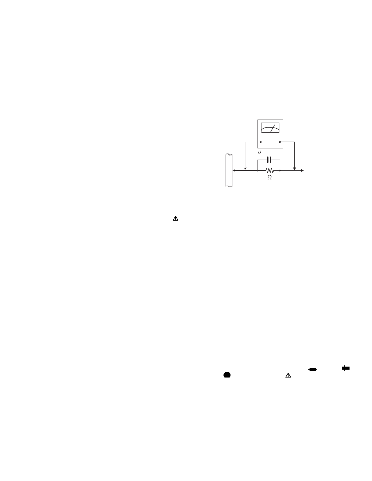
• Alternate check method
Plug the AC line cord directly into the AC outlet. Use an
AC voltmeter having, 1,000Ω per volt or more sensitivity
in the following manner. Connect a 1,500Ω 10W resistor
paralleled by a 0.15µF AC-type capacitor between an ex-
posed metal part and a known good earth ground.
Measure the AC voltage across the resistor with the AC
voltmeter.
Move the resistor connection to each exposed metal
part, particularly any exposed metal part having a return
path to the chassis, and measure the AC voltage across
the resistor. Now, reverse the plug in the AC outlet and
repeat each measurement. Voltage measured any must
not exceed 0.75 V AC (r.m.s.). This corresponds to 0.5
mA AC (r.m.s.).
AC VOLTMETER
(Having 1000
ohms/volts,
or more sensitivity)
0.15 F AC TYPE
Place this
probe on
1500 10W
Good earth ground
1.2 Warning
(1) This equipment has been designed and manufactured to
meet international safety standards.
(2) It is the legal responsibility of the repairer to ensure that
these safety standards are maintained.
(3) Repairs must be made in accordance with the relevant
safety standards.
(4) It is essential that safety critical components are replaced
by approved parts.
(5) If mains voltage selector is provided, check setting for local
voltage.
1.3 Caution
Burrs formed during molding may be left over on some parts
of the chassis.
Therefore, pay attention to such burrs in the case of preforming repair of this system.
1.4 Critical parts for safety
In regard with component parts appearing on the silk-screen
printed side (parts side) of the PWB diagrams, the parts that are
printed over with black such as the resistor ( ), diode ( )
and ICP ( ) or identified by the " " mark nearby are critical
for safety. When replacing them, be sure to use the parts of the
same type and rating as specified by the manufacturer.
(This regulation dose not Except the J and C version)
each exposed
metal part.
(No.MB330)1-3
Page 4

1.5 Safety Precautions (U.K only)
(1) This design of this product contains special hardware and many circuits and components specially for safety purposes. For con-
tinued protection, no changes should be made to the original design unless authorized in writing by the manufacturer. Replacement parts must be identical to those used in the original circuits.
(2) Any unauthorised design alterations or additions will void the manufacturer's guarantee; furthermore the manufacturer cannot
accept responsibility for personal injury or property damage resulting therefrom.
(3) Essential safety critical components are identified by ( ) on the Parts List and by shading on the schematics, and must never
be replaced by parts other than those listed in the manual. Please note however that many electrical and mechanical parts in
the product have special safety related characteristics. These characteristics are often not evident from visual inspection. Parts
other than specified by the manufacturer may not have the same safety characteristics as the recommended replacement parts
shown in the Parts List of the Service Manual and may create shock, fire, or other hazards.
(4) The leads in the products are routed and dressed with ties, clamps, tubings, barriers and the like to be separated from live parts,
high temperature parts, moving parts and/or sharp edges for the prevention of electric shock and fire hazard. When service is
required, the original lead routing and dress should be observed, and it should be confirmed that they have been returned to
normal, after re-assembling.
1.5.1 Warning
(1) Service should be performed by qualified personnel only.
(2) This equipment has been designed and manufactured to meet international safety standards.
(3) It is the legal responsibility of the repairer to ensure that these safety standards are maintained.
(4) Repairs must be made in accordance with the relevant safety standards.
(5) It is essential that safety critical components are replaced by approved parts.
(6) If mains voltage selector is provided, check setting for local voltage.
Burrs formed during molding may be left over on some parts of the chassis. Therefore,
pay attention to such burrs in the case of preforming repair of this system.
1-4 (No.MB330)
Page 5
1.6 Preventing static electricity
Electrostatic discharge (ESD), which occurs when static electricity stored in the body, fabric, etc. is discharged, can destroy the laser
diode in the traverse unit (optical pickup). Take care to prevent this when performing repairs.
1.6.1 Grounding to prevent damage by static electricity
Static electricity in the work area can destroy the optical pickup (laser diode) in devices such as laser products.
Be careful to use proper grounding in the area where repairs are being performed.
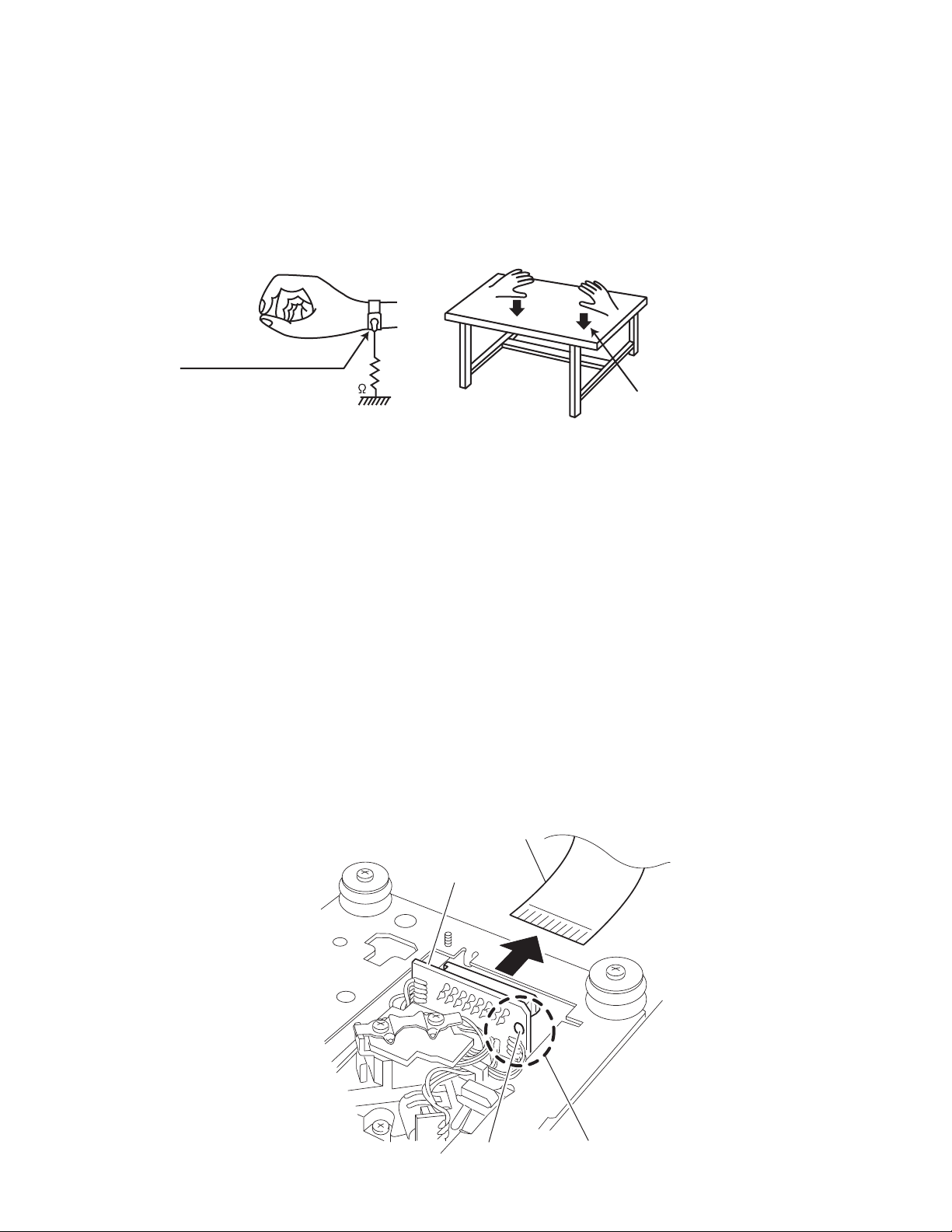
(1) Ground the workbench
Ground the workbench by laying conductive material (such as a conductive sheet) or an iron plate over it before placing the
traverse unit (optical pickup) on it.
(2) Ground yourself
Use an anti-static wrist strap to release any static electricity built up in your body.
(caption)
Anti-static wrist strap
1M
Conductive material
(conductive sheet) or iron palate
(3) Handling the optical pickup
• In order to maintain quality during transport and before installation, both sides of the laser diode on the replacement optical
pickup are shorted. After replacement, return the shorted parts to their original condition.
(Refer to the text.)
• Do not use a tester to check the condition of the laser diode in the optical pickup. The tester's internal power source can easily
destroy the laser diode.
1.7 Handling the traverse unit (optical pickup)
(1) Do not subject the traverse unit (optical pickup) to strong shocks, as it is a sensitive, complex unit.
(2) Cut off the shorted part of the flexible cable using nippers, etc. after replacing the optical pickup. For specific details, refer to the
replacement procedure in the text. Remove the anti-static pin when replacing the traverse unit. Be careful not to take too long a
time when attaching it to the connector.
(3) Handle the flexible cable carefully as it may break when subjected to strong force.
(4) I t is not possible to adjust the semi-fixed resistor that adjusts the laser power. Do not turn it.
1.8 Attention when traverse unit is decomposed
*Please refer to "Disassembly method" in the text for the pickup unit.
• Apply solder to the short land sections before the flexible wire is disconnected from the connecto on the servo board. (If the flexible
wire is disconnected without applying solder, the pickup may be destroyed by static electricity.)
• In the assembly, be sure to remove solder from the short land sections after connecting the flexible wire.
Card wire
CD pickupz board
Unsolder
Short-circuit point
(No.MB330)1-5
Page 6
1.9 Important for laser products
!
1.CLASS 1 LASER PRODUCT
2.DANGER : Invisible laser radiation when open and inter
lock failed or defeated. Avoid direct exposure to beam.
3.CAUTION : There are no serviceable parts inside the
Laser Unit. Do not disassemble the Laser Unit. Replace
the complete Laser Unit if it malfunctions.
4.CAUTION : The CD,MD and DVD player uses invisible
laser radiation and is equipped with safety switches which
prevent emission of radiation when the drawer is open and
the safety interlocks have failed or are defeated. It is
dangerous to defeat the safety switches.
5.CAUTION : If safety switches malfunction, the laser is able
to function.
6.CAUTION : Use of controls, adjustments or performance of
procedures other than those specified here in may result in
hazardous radiation exposure.
Please use enough caution not to
see the beam directly or touch it
in case of an adjustment or operation
check.
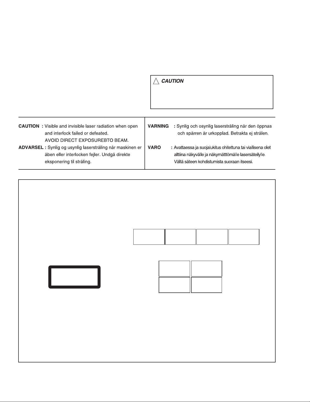
REPRODUCTION AND POSITION OF LABELS
WARNING LABEL
CAUTION : Visible and Invisible
laser radiation when open and
interlock failed or defeated.
AVOID DIRECT EXPOSURE TO
BEAM. (e)
CLASS 1
LASER PRODUCT
ADVARSEL : Synlig og usynlig
laserstråling når maskinen er
åben eller interlocken fejeler.
Undgå direkte eksponering til
stråling. (d)
CAUTION : Visible and Invisible
laser radiation when open and
interlock failed or defeated.
AVOID DIRECT EXPOSURE TO
BEAM. (e)
VARNING : Synlig och
osynling laserstrålning när
den öppnas och spärren är
urkopplad. Betrakta ej
strålen. (s)
VARNING : Synlig och
osynling laserstrålning när
den öppnas och spärren är
urkopplad. Betrakta ej
strålen. (s)
VARO : Avattaessa ja suojalukitus
ohitettuna tai viallisena olet alttiina
näkyvälle ja näkymättömälle
lasersäteilylle. Vältä säteen
kohdistumista suoraan itseesi. (f)
ADVARSEL : Synlig og usynlig
laserstråling når maskinen er
åben eller interlocken fejeler.
Undgå direkte eksponering til
stråling. (d)
VARO : Avattaessa ja suojalukitus
ohitettuna tai viallisena olet alttiina
näkyvälle ja näkymättömälle
lasersäteilylle. Vältä säteen
kohdistumista suoraan itseesi. (f)
1-6 (No.MB330)
Page 7

SECTION 2
SPECIFIC SERVICE INSTRUCTIONS
This service manual does not describe SPECIFIC SERVICE INSTRUCTIONS.
(No.MB330)1-7
Page 8
SECTION 3
DISASSEMBLY
3.1 Main body
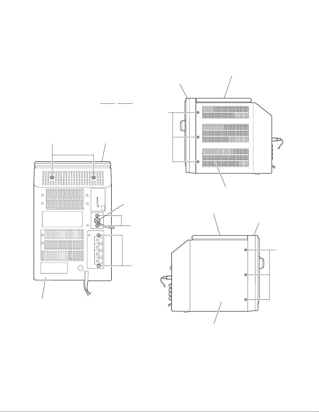
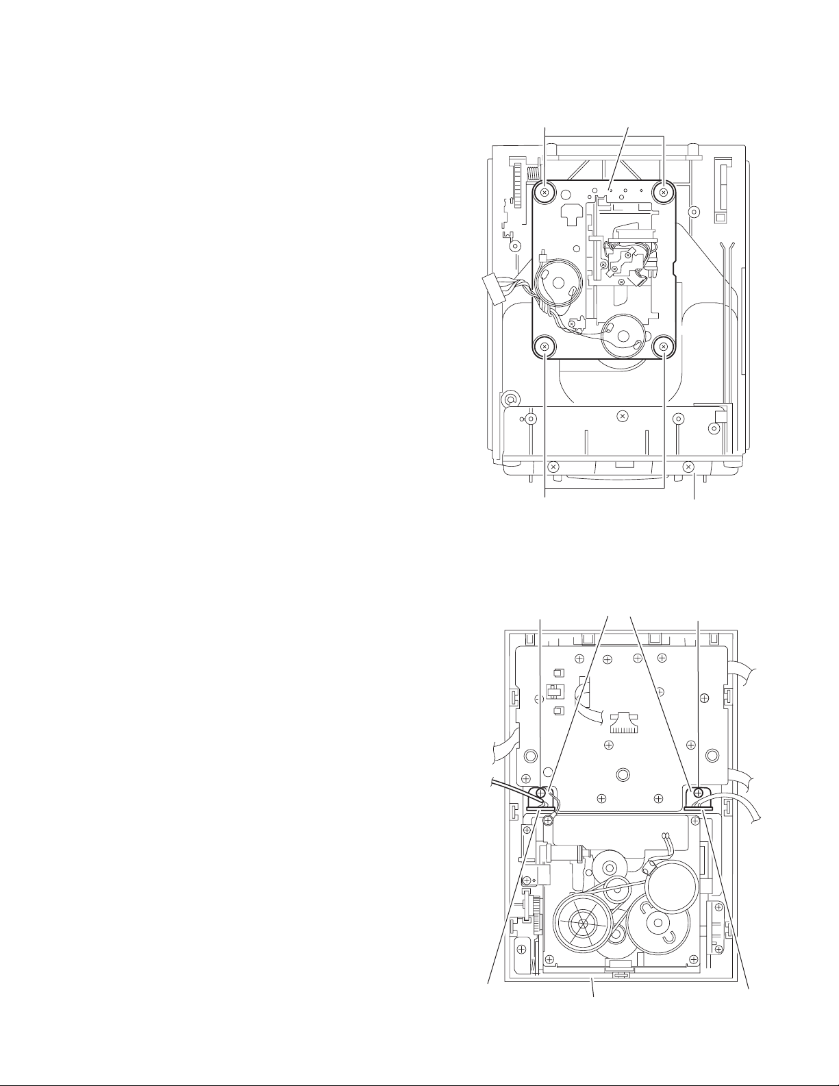
3.1.1 Removing the front panel assembly
(See Fig.1 ~ 6)
(1) Disconnect the antenna cord on the back of the body.
(2) Remove the two screws A, the two screws B and the two
screws D on the back of the body respectively.
(3) Remove the six screws E on both sides of the body.
(4) Remove the screw F on the bottom of the body.
(5) Move the front panel assembly in the direction of the arrow
and remove. Disconnect connector CN402
main board and disconnect the wire from FM-ANT.
CAUTION:
When reassembling the front panel assembly, fit the right and
left joints a to the notch.
, CN801 on the
CD mechanism assembly
Front panelh assembly
E
A
CD mechanism assembly
Antenna cord
Rear cover assembly
Fig.2
CD mechanism assembly
Front panelh assembly
D
E
B
Rear cover assembly
1-8 (No.MB330)
Fig.1
Rear panel assembly
Fig.3
Page 9
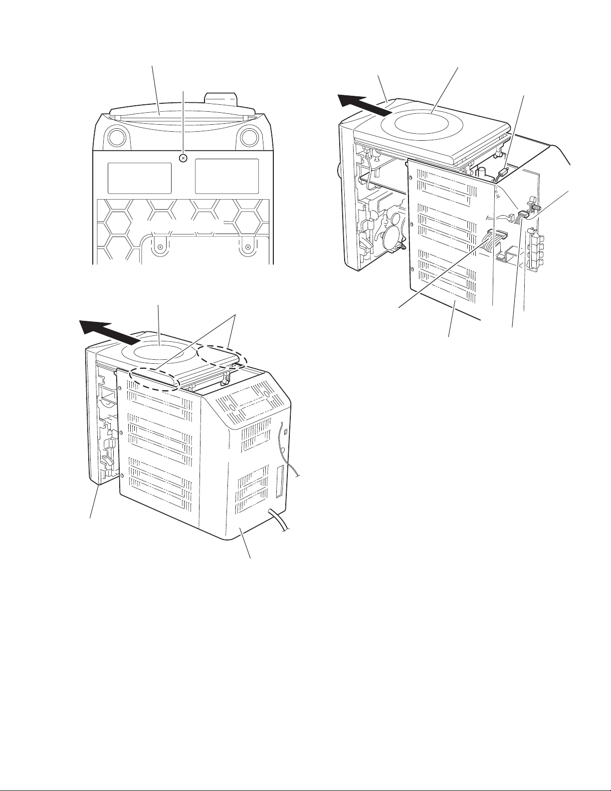
Front panel assembly
F
Rear panel assembly
Fig.4
CD mechanism assembly
Joint a
Front panel assembly
CD mechanism assembly
FM-ANT
Main board
CN402
CN801
Rear cover assembly
Front panel assembly
Fig.6
Rear cover assembly
Fig.5
(No.MB330)1-9
Page 10
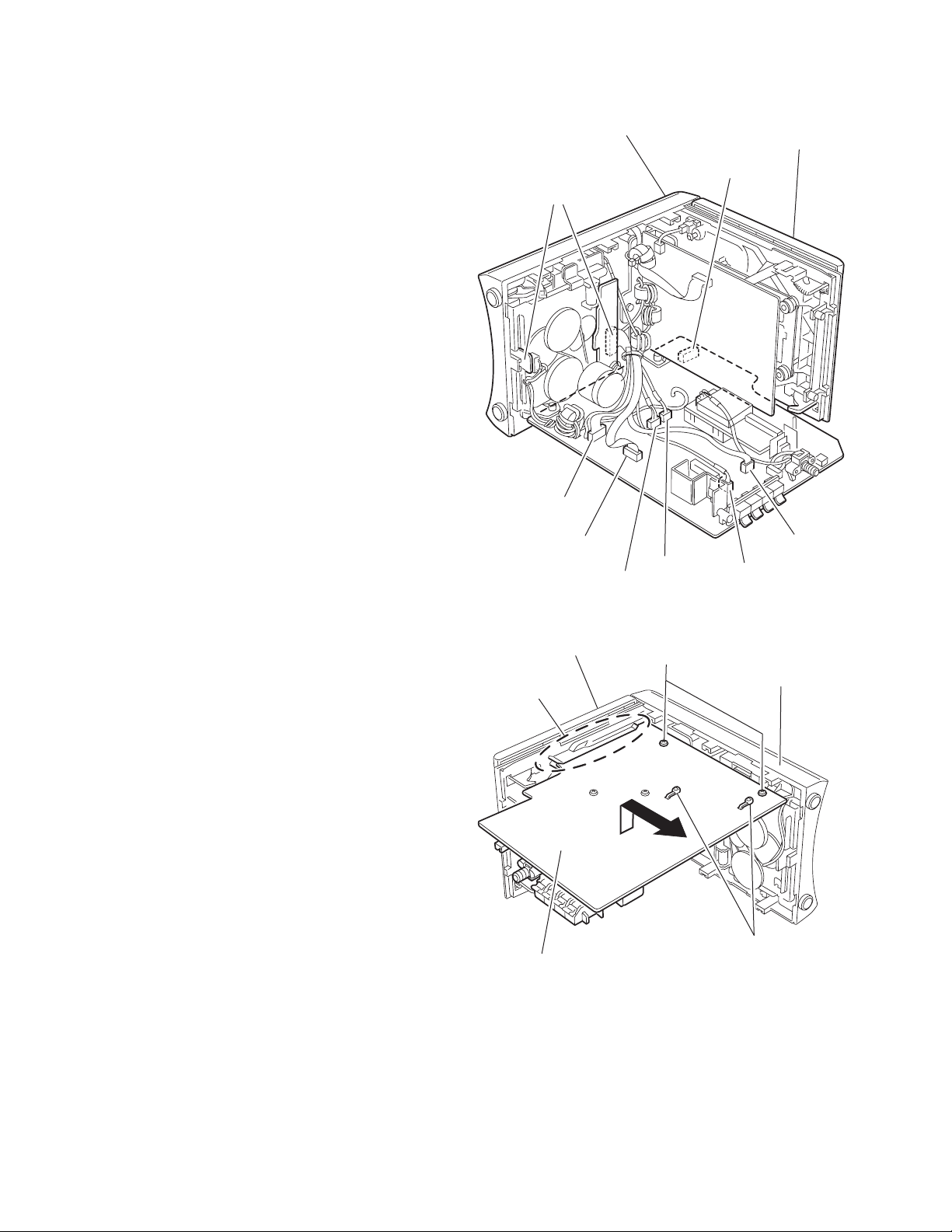
3.1.2 Removing the main board
(See Fig.7, 8)
• Prior to performing the following procedure, remove the front
panel assembly.
(1) Disconnect the wire from all connectors on the main board.
(2) Disconnect the wire from the two connectors on the cas-
sette mechanism assembly.
(3) Release the two bands attaching the wire to the main
board.
(4) Remove the two screws G from the front panel assembly.
Release the joint b.
Front panel assembly
CD mechanism assembly
Main board
CN203
CN303
CN301
CD mechanism assembly
CN103
CN302
CN403
CN401
CD mechanism assembly
Joint b
Main board
Fig.7
G
Front panel assembly
Band
Fig.8
1-10 (No.MB330)
Page 11
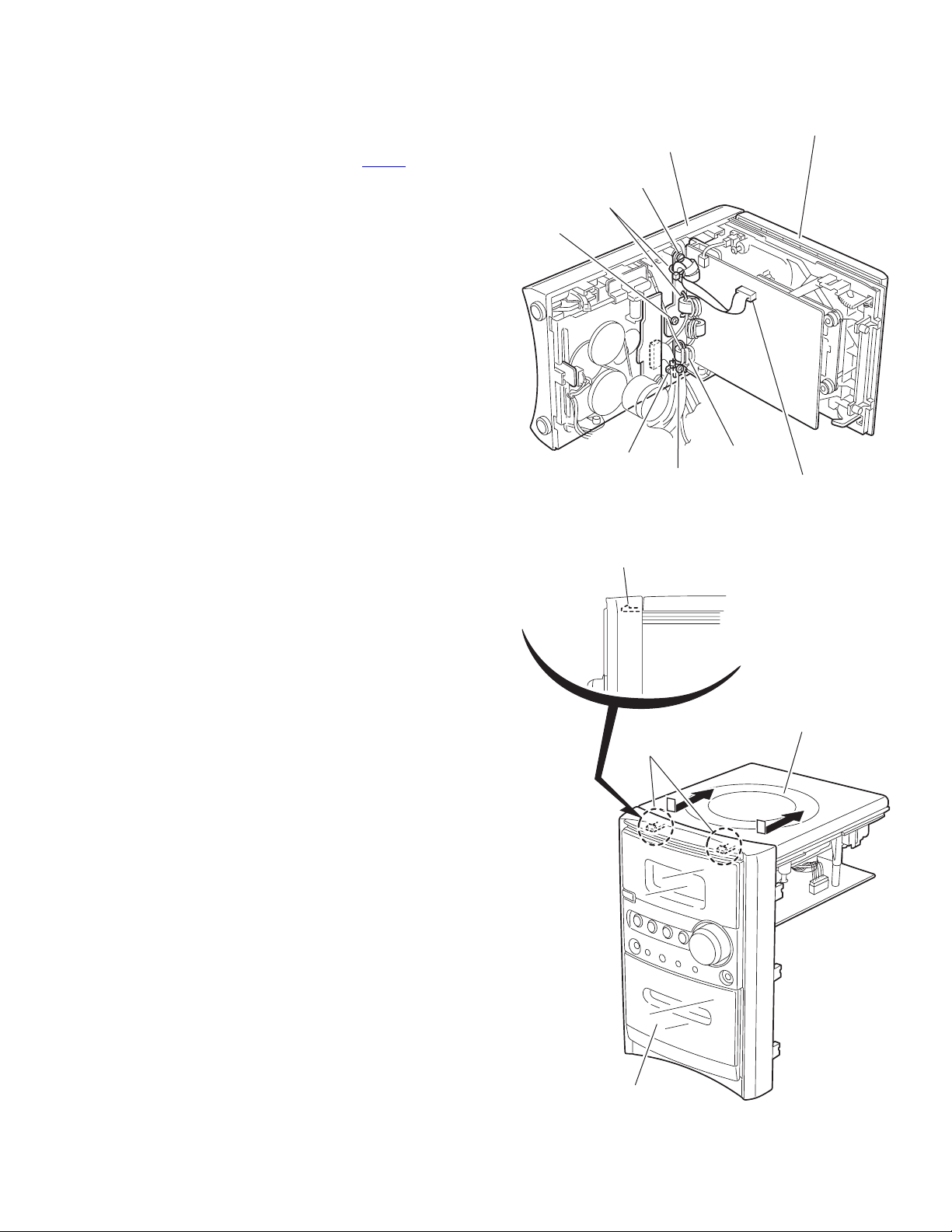
3.1.3 Removing the CD mechanism assembly
(See Fig.9, 10)
• Prior to performing the following procedure, remove the front
panel assembly and the main board.
(1) Release the four bands setting the wire.
(2) Disconnect the wire from connector CN607
mechanism board respectively.
(3) Remove the three screws H attaching the CD mechanism
assembly.
(4) Release the joint d to remove the CD mechanism assem-
bly from the front panel assembly.
on the CD
CD mechanism assembly
Front panel assembly
H
Band
H
Band
Joint d
Joint d
H
Band
CD mechanism board
CN607
Fig.9
CD mechanism assembly
Front panel assembly
Fig.10
(No.MB330)1-11
Page 12

3.1.4 Removing the CD mechanism assembly
(See Fig.11 ~ 13)
• Prior to performing the following procedure, remove the front
panel assembly, the main board and the CD mechanism assembly.
CAUTION:
Before disconnecting the card wire from connector CN608
the CD mechanism board and from CD pickup board, solder
the short-circuit point on the CD pickup board. If you do not follow this instruction, the pickup may be damaged.
(1) Disconnect the wire from connector CN602
the CD mechanism board.
(2) Remove the four screws J attaching the CD mechanism
board.
(3) Move the CD mechanism board as shown in the figure 12
and solder the short-circuit point on the CD pickup board.
(4) Disconnect the card wire from connector CN608
mechanism board.
CAUTION:
Make sure to unsolder the short-circuit point after reconnecting
the card wire to the CD pickup board and to connector CN608
on the CD mechanism board.
and CN609 on
on
on the CD
CD mechanism board
Card wire
CN602
CN608
CD mechanism board
CN609
J
CN608
CD mechanism assembly
Short-circuit point
CD mechanism assembly
Fig.12
Card wire
CD pickupz board
J
CN602
Fig.11
1-12 (No.MB330)
Short-circuit point
Unsolder
Fig.13
Page 13
3.1.5 Removing the CD mechanism
A
(See Fig.14)
• Prior to performing the following procedure, remove the front
panel assembly, the main board, the CD mechanism assembly
and the CD mechanism board.
(1) Remove the four screws K attaching the CD mechanism.
K
CD mechanism
3.1.6 Removing the headphone board/ AUX board
(See Fig.15)
• Prior to performing the following procedure, remove the front
panel assembly, the main board and the CD mechanism assembly.
(1) Remove the screw M attaching the bracket and detach the
headphone board.
(2) Remove the screw N attaching the bracket and detach the
AUX board.
N
K
CD mechanism assembly
Fig.14
Bracket
M
UX board
Front panel assembly
Fig.15
Head phones board
(No.MB330)1-13
Page 14
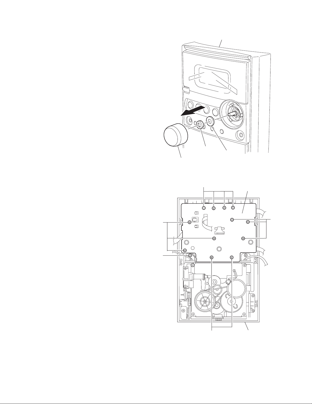
3.1.7 Remove the LCD board (See Fig.16, 17)
• Prior to performing the following procedure, remove the front
panel assembly, the main board and the CD mechanism assembly.
(1) From the front panel, pull out the volume knob and remove
the nut and the washer.
(2) Remove the twelve screws P attaching the LCD board and
remove the screw Q setting the wire.
Front panel assembly
P
Q
Volume konb
Nat
P
Washer
Fig.16
LCD board
P
1-14 (No.MB330)
P
Fig.17
Front panel assembly
Page 15
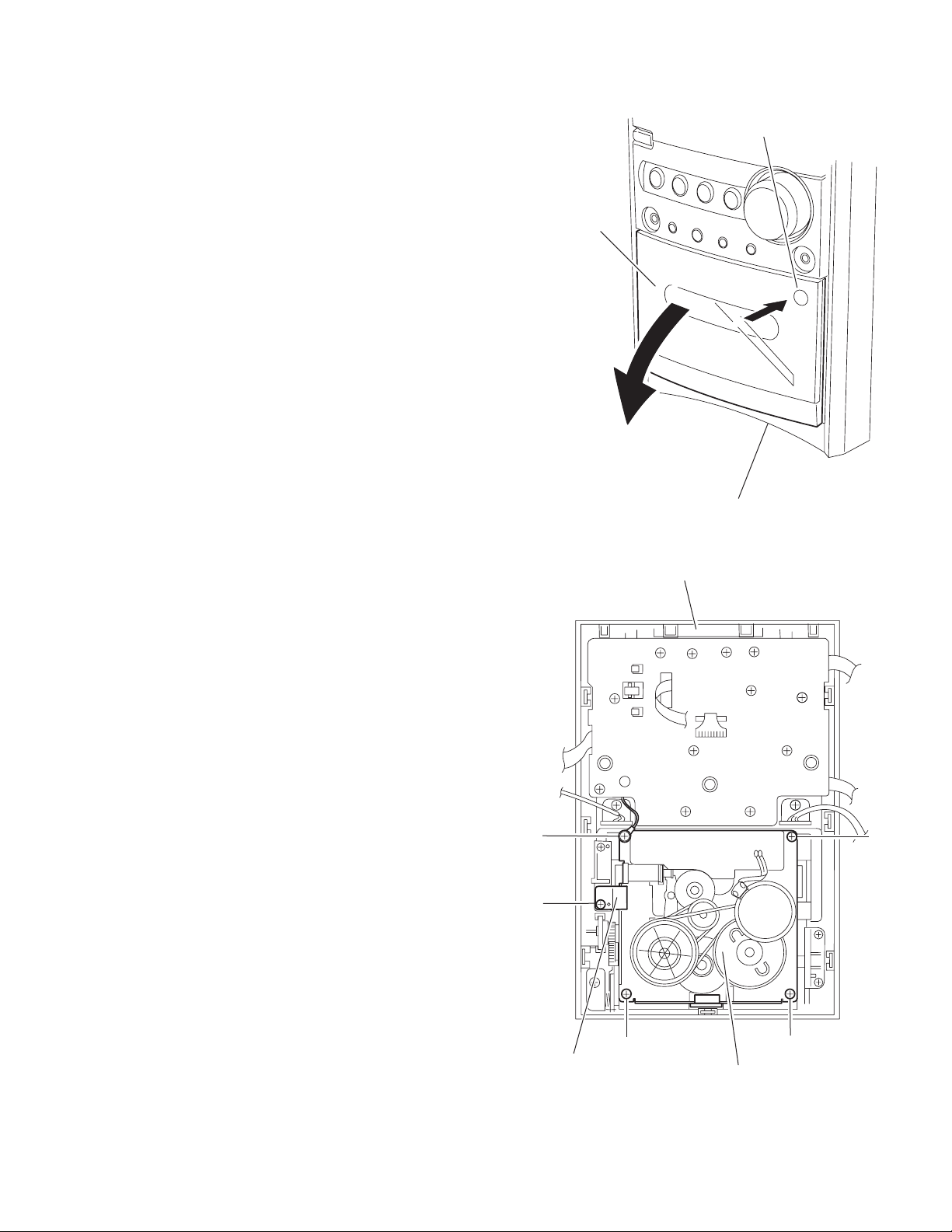
3.1.8 Removing the cassette mechanism assembly
(See Fig.18, 19)
• Prior to performing the following procedure, remove the front
panel assembly and the main board.
(1) Push 'PUSH OPEN' on the front panel to open the cassette
door.
(2) Remove the screw R attaching the bracket of the cassette
mechanism assembly.
(3) Remove the two screws S and the two screws T attaching
the cassette mechanism assembly.
PUSH OPEN
Cassette door
Front panel assembly
S
R
Fig.18
Front panel assembly
S
Bracket
T
Cassette mechaanism assembly
Fig.19
T
(No.MB330)1-15
Page 16
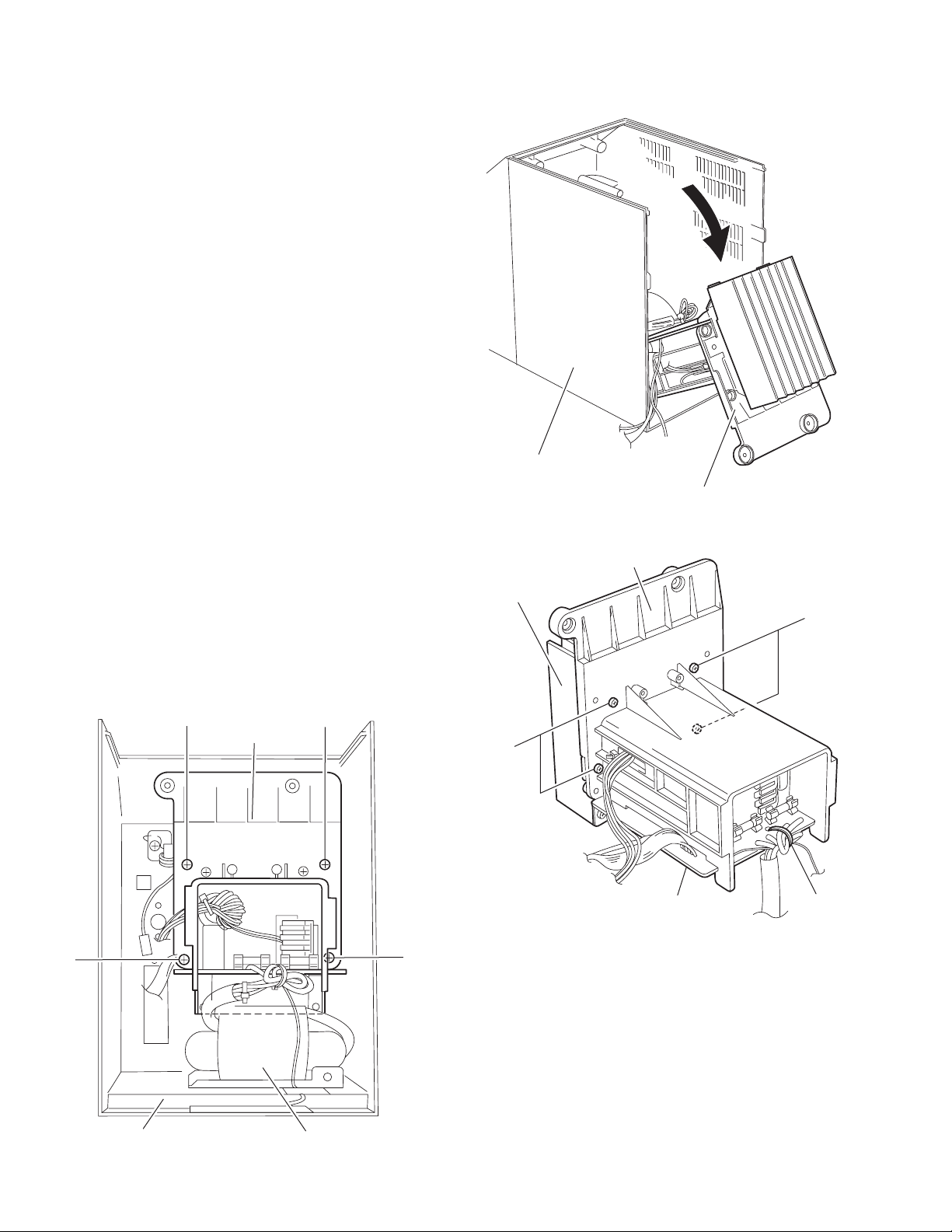
3.1.9 Removing the heat sink/power board
(See Fig.20 ~ 27)
• Prior to performing the following procedure, remove the front
panel assembly.
(1) Remove the four screws U attaching the holder in the pow-
er unit section.
(2) Move the power unit section with the wire from the rear cov-
er temporarily. If necessary, release the band and unsolder
the wire on the power board.
(3) Remove the four screws Y and the screw A’ attaching the
holder.
(4) Release the wire from the band e and move the holder in
the direction of the arrow to release from the joint f.
(5) Remove the four screws B’ and two screws D’ attaching
the heat sink.
(6) Remove the two screws E’ attaching the power board.
3.1.10 Removing the power transformer assembly
(See Fig.27, 28)
• Prior to performing the following procedure, remove the front
panel assembly and the power unit section.
(1) Remove the four screws F’ attaching the power transform-
er assembly. The bracket comes off at the bottom of the
rear cover.
(2) Remove the screw G’ attaching the power cord folder.
(3) Remove the two screws H’ attaching the AC connector
board.
Rear cover
Ppwer unit section
Fig.21
3.1.11 Removing the FM antenna board
(See Fig.28)
• Prior to performing the following procedure, remove the front
panel assembly and the power unit section.
(1) From the rear cover assembly, remove the screw J’ attach-
ing the FM antenna board.
(2) From the FM antenna board, unsolder the FM antenna
wire.
U
Power unit section
U
U
U
Heat sink
Y
Holder
Power board
Fig.22
Y
Band
Rear cover
1-16 (No.MB330)
Power trnsfomer assembly
Fig.20
Page 17

Unsolder
Band
Power board
A'
Heat sink
Band e
B'
Heat sink
Power board
Joint f
Unsolder
Heat sink
Band
B'
Holder
Power board
Unsolder
Fig.23
B'
Fig.25
Bracket
E'
Power board
Power board
D'
Fig.26
Fig.24
(No.MB330)1-17
Page 18

r
F'
Power trnsfomer assembly
F'
FM antenna board
Rear cove
Fig.27
Rear cover
J'
Power cord folder AC connect board
1-18 (No.MB330)
G'
Fig.28
H'
Page 19

3.1.12 Removing the DAB module board
(See Fig.29,30)
• Prior to performing the following procedure, remove the front
panel assembly.
• Reference; It is not necessary to remove the main board.
(1) From the left side of the body, remove the two screws K’
attaching the DAB module board.
(2) Disconnect the wire from connector CN3
ule board.
(3) Disconnect the DAB module board from connector JK10 on
the main board by pulling out. The holder comes off with
the DAB module board.
(4) Release the four joints g of the holder and remove the DAB
module board.
on the DAB mod-
CD mechanism assembly
K'
Front panel assembly
Main board
Fig.29
DAB module board
CN3
CD mechanism assembly
Front panel assembly
Joint g
JK10
Main board
Joint g
DAB module board
Holder
Fig.30
(No.MB330)1-19
Page 20

4.1 Cassette amp. section
Item Measuring condition Check and adjustment procedure Standard value Adjusting point
Head azimuth
adjustment
Tape speed
and wow/
flutter check
and adjust
Test tape : 8 kHz
Signal output : phone
(with 32 ohm load)
Test tape : 3 kHz
Signal output : phone
(with 32 ohm load)
SECTION 4
ADJUSTMENT
1.Playback the test tape (8kHz).
2.Adjust the head azimuth adjusting screw so
that the phase difference between the R
and L channels minimized at an output level
that is within 2 dB of the maximum output
level. After this adjustment, lock the head
azimuth adjusting screw with screw sealant
to cover more than a half of the screw head.
3.When the head azimuth is maladjusted,
correct it with the head azimuth adjusting
screw.
1.Playback the test tape (3kHz) by the end
position.
2.Connect a frequency counter and check that
it reads between 2940 and 3090 Hz. If not,
adjust the frequency with the motor semi fixed resistor.
3.Check that the wow/flutter is within 0.38%.
(unweighted)
Output level :
within 2dB of
maximum output
level
Phase difference
L and R channel:
Minimum
2940 to 3090 Hz
Within 0.38%
(unweighted)
Head azimuth
adjusting screw
(To be used only
after head
replacement)
Tape speed :
Motor semifixed resistor
Check only
Bias frequency
check
REC and PB
frequency
response
adjustment
Tape : Normal
Signal out : Cassette
REC/PLAY HEAD
Test tape : Normal
Signal input : FM 22.5
DEV 60dB with
Emphasis
Signal output : phone
(with 32 ohm load)
Set the TUNER or CD function and with TAPE
to record. Check to see if the frequency at the
measuring point R225 or R226 is 80kHz 1
kHz. If not adjust L203 until the frequency
counter indicates 80 kHz 1 kHz.
At TUNER, set the BAND to the FM position,
and record the reference 1 kHz siganl and 8
kHz sigan alternately repeatedly. While playing
bak the recorded signal differ from that of the
1 kHz signal by within 0 (+3 to -6) dB.
L203
R225/R226
Level difference
between REC
and PB : within
0 (+3 to -6) dB.
1-20 (No.MB330)
Page 21

4.2 Tuner section
Item Measuring condition Check and adjustment procedure Standard value Adjusting point
AM IF
adjustment
AM tracking
adjustment
FM IF
adjustment
FM tracking
adjustment
Signal input : T002
Signal output : T007
Signal input : Loop
antenna
Signal output : phone
(with 32 ohm load)
Signal input : T004
Signal output : T007
Signal input : ANT IN
Signal output : phone
(with 32 ohm load)
1.T026 and T006 connected with a 3.3k ohm
resistor.
2.Set the intermediate frequency sweep
generator to AM 450 kHz.
3.T021 and GND connected with a 220 ohm
resistor and a 104 capacitor in serials.
Adjust the T102 for maximum and center
output.
4.T022 and GND connected with a 220 ohm
resistor and a 104 capacitor in serials.
Adjust the T101 for maximum and center
output.
5.T002 input 2mV 450kHz signal without MOD.
Adjust the T103 until the voltage between
T009 and T010 is 0mV 3mV.
1.Set the TUNER at 1629 kHz adjust T104
until the test pin of T008 voltage at 7.0V
0.1V.
2.Set the TUNER at 522 kHz, check the pin of
T008 voltage at 1.1V 0.5V.
3.Set the TUNER and S/G at 603 kHz, adjust
T106 for maximum output.
4.Set the TUNER and S/G at 1404 kHz, adjust
TC102 for maximum output.
5.Repeat the above step 3 and 4.
1.Set the TUNER at 108 MHz, adjust L102
until the test pin of T008 voltage at 8.0 V
0.1V.
2.Set the TUNER at 87.5 MHz, check the pin
of T008 voltage at 1.6 V 0.5V.
3.Short T011 and GND, adjust the T105 until
the voltage between T009 and T010 is 0 mV
0.5V.
1.Set the TUNER and S/G at 90 MH, adjust
L101 for maximum output.
2.Set the TUNER and S/G at106 MHz, adjust
TC101 for maximum output.
3.Repeat the above step 1 and 2.
T101
T102
T103
T104
T106
TC102
T105
L102
L101
TC101
(No.MB330)1-21
Page 22

4.3 Location of adjusting parts
Cassette mechanism
Main board assembly
Tape Speed Adj.
-
+
CASSETTE MOTOR
L203
T105
T103
T101
L102
VR101
T102
TC101
T104
L101
TC102
T106
1-22 (No.MB330)
Page 23

SECTION 5
TROUBLESHOOTING
Ciruit Symptom Cause and Remedy
General No sound Defect in IC801
Check voltages. Replace if necessary.
Defect in IC301
Check voltages. Replace if necessary.
AM No sound, Weak sound
(Low sensitivity)
FM No sound, Weak sound
(Low sensitivity)
Tape No sound/Recording,
Unsteady tape sound, Weak sound
CD Cannot read the TOC.
No sound
Defect in IF T101, T102, T103
Check resistance, voltage and current. Replace as needed.
Defect AM antenna coil T106 or oscilloscope coil T104
Replace if necessary.
Intermediate frequency tuning faulty
Readjust.
RF tracking faulty
Readjust.
Defective IC101
Check viltagese. Replace if necessary.
Defective IC101
Check viltagese. Replace if necessary.
Intermediate frequency tuning faulty
Readjust.
Dirty capstan or head
Clean the capstan or head with alcohol.
Defective IC201
Check voltages. Replace if necessary.
Cassette erasure provention tabs broken out
Replace tape or over tab openings with adhesive tape.
Moisture has formed inside the CD deck
Waite about 20 to 30 minutes.
Defective IC601
Check voltages. Replace if necessary.
Defective IC602
Check voltages. Replace if necessary.
Defective IC603
Check voltages. Replace if necessary.
Defective IC605
Check voltages. Replace if necessary.
Defective IC606
Check voltages. Replace if necessary.
Defective IC608
Check voltages. Replace if necessary.
Defective IC609
Check voltages. Replace if necessary.
Defective IC610
Check voltages. Replace if necessary.
Defective IC611
Check voltages. Replace if necessary.
Defect in the CD pickup mechanism
Replace as required.
(No.MB330)1-23
Page 24

Victor Company of Japan, Limited
AV & MULTIMEDIA COMPANY AUDIO/VIDEO SYSTEMS CATEGORY 10-1,1chome,Ohwatari-machi,Maebashi-city,371-8543,Japan
(No.MB330)
Printed in Japan
WPC
Page 25

SCHEMATIC DIAGRAMS
MICRO COMPONENT SYSTEM
UX-HB4
CD-ROM No.SML200410
Contents
Wiring connection
Block diagram
Standard schematic diagrams
Printed circuit boards
COPYRIGHT 2004 Victor Company of Japan, Limited.
CA-UXHB4 SP-UXHB4SP-UXHB4
Area suffix
B ------------------------------ U.K.
2-1
2-2
2-3
2-7 to 9
No.MB330SCH
2004/10
Page 26

In regard with component parts appearing on the silk-screen printed side (parts side) of the PWB diagrams, the
parts that are printed over with black such as the resistor ( ), diode ( ) and ICP ( ) or identified by the " "
mark nearby are critical for safety.
Page 27

Wiring connection
P/N:11-00004-27
UX-HB4 AC CONNECT PCB
6
1
P/N:15-80300-02
H300 TRANSFORMER
Color codes are shown below
1 --- BROWN
2 --- RED
3 --- ORANGE
4 --- YELLOW
5 --- GREEN
6 --- BLUE
7 --- VIOLET
8 --- GREY
9 --- WHITE
0 --- BLACK
P/N:30-00300-02L
6
1
P/N:20-41092-81
P/N:20-41092-48
CN501
CN503
RED
CN507
P/N:11-0004-22
UX-HB4 CPU&KEY PCB
P/N:11-0004-20
UX-HB4 MAIN PCB
CN103
CN201
0204990
CNM705
RED
P/N:20-41092-71
CN302
CN301
P/N:20-61031-21
P/N:25-23050-82
P/N:20-61031-60
CN401
RED
P/N:11-00004-25
UX-HB4 LED PCB
P/N:20-41072-60
FM ANT
CN102
P/N:20-42022-60
CON801
RED
P/N:29-00300-00
P/N:11-00004-26
UX-HB4 FM ANT PCB
ANT2 ANT1
P/N:29-00300-00
P/N:23-04910-80
CN608
P/N:25-61060-80
16
1
CN802
P/N:98-00010-80
CD MECH
BOTTOM SIDE
16 1
P/N:31-90080-80
CN607
P/N:20-41061-81
FM ANT
P/N:11-00004-21
UX-HB4 CD PCB
CN606
CN808
CN805
209
P/N:20-41022-87
6
5
1
2
4
3
AM LOOP ANT
RED
CO COJA SA
DAB ANT
P/N:11-80300-01
H300 POWER PCB
CNB02
CNB01
P/N:11-00004-24
RED
CON401
UX-HB4 PHONE PCB
9
CON301
0
2
P/N:20-61083-80
P/N:11-00004-23
UX-HB4 AUX PCB
P/N:94-34309-00
CASS LOGIC DECK
BOTTOM SIDE
PN:20-61010-80
CN402
CN202
CN202
CN303
1133
RED
CN403
RED
P/N:20-42041-82
2
0
9
2
RIGHT SPEAKERS
LEFT SPEAKERS
1
8
9
PN:20-42041-81
RED
P/N:20-41092-57
2-1
Page 28

Block diagram
LCD DISPLAY
MODULE
(S6A0094)
KEY SCAN
GM16312
REMOTE
CONTROL
(PT2222)
RDS
BU1924F
MCU
SM89516A
TUNER
SECTION
TEA5757
IC
FRONTIER
FS2020
DAB MODULE
2
IC
TUNER L/R
DAB L/R
TAPE L/R
AUX IN L/R
FUNCTION SELECTOR
2
PRE. EQ
CASS
LOGIC DECK
AN7312
L/R
POWER AMP
LA4725
AUX IN
RCA JACK
L/R SPEAKER
VOLUMN CONTROL
PT2314
MUTE
POWER AMP
LA4808
EAR PHONE
MEMORY
24C01
IC
CD L/R
POWER EN
2
CD SECTION
CD PICK UP
TCP11K2X
S1L9226+S5L9290
EEPROM
W27C020
MPEG
DECODER
ESS3890
DRAM
4MB(16M)
POWER SUPPLY SECTION
FOR AMP
FOR CD
FOR TUNER
FOR DAB
FOR TAPE
VOLTAGE
REGULATOR
STANDBY
RECTIFIER
RECTIFIER
AC SUPPLY
2-2
Page 29

Standard schematic diagrams
Power circuit
Parts are safety assurance parts.
When replacing those parts make
sure to use the specified one.
2-3
Page 30

Main circuit
2-4
Parts are safety assurance parts.
When replacing those parts make
sure to use the specified one.
Page 31

CD circuit
Parts are safety assurance parts.
When replacing those parts make
sure to use the specified one.
2-5
Page 32

Display circuit
2-6
Parts are safety assurance parts.
When replacing those parts make
sure to use the specified one.
Page 33

Printed circuit boards
Main board
( forward side) ( reverse side)
2-7
Page 34

Display board
( forward side )
CD board
( forward side )
( reverse side )
( reverse side )
2-8
Page 35

Power board
( forward side )
( reverse side )
2-9
Page 36

Victor Company of Japan, Limited
AV & MULTIMEDIA COMPANY AUDIO/VIDEO SYSTEMS CATEGORY 10-1,1chome,Ohwatari-machi,Maebashi-city,371-8543,Japan
(No.MB330SCH)
Printed in Japan
WPC
Page 37

PARTS LIST
[ UX-HB4 ]
* All printed circuit boards and its assemblies are not available as service parts.
Area suffix
B ------------------------------- U.K.
MB330
- Contents -
Exploded view of general assembly and parts list (Block No.M1)
Electrical parts list (Block No.01~04)
Packing materials and accessories parts list (Block No.M3)
3- 2
3- 6
3-14
3-1
Page 38

Exploded view of general assembly and parts list
3
1
0
6
y
Block No.
M
M
1
M
81
81
66
8181
41
91
76
42
58
77
72
20
Phone board
71
75
46
60
59
71
72
Power board
72
62
61
80
78
Main board
49
48
79
50
73
73
64
72
51
66
83
AC Connect
71
71
65
board
87
71
52
LED board
FM ANT
board
79
88
53
79
57
Displa
55
80
66
82
32
7
39
3-2
40
38
37
36
35
34
32
33
29
31
11
29
29
73
27
28
26
25
30
47
24
72
74
84
23
73
71
2
AUX board
22
Page 39

Block No.
M
M
1
M
81
81
66
8181
66
1
77
58
71
59
71
60
72
62
61
80
78
Main board
79
73
64
72
66
83
AC Connect
71
65
87
board
71
FM ANT
board
79
88
79
57
55
80
66
82
32
73
65
67
82
85
56
89
90
5
68
69
73
2
3
6
4
8
7
9
10
11
12
13
72
20
hone board
29
32
31
33
11
75
46
29
29
73
Power board
72
27
26
28
48
25
49
30
50
47
24
73
72
74
51
71
84
52
LED board
73
23
22
53
Display board
71
AUX board
18
20
73
72
16
14
71
70
15
70
CD board
72
3-3
Page 40

General Assembly
Symbol No. Part No. Part Name Description Local
1 OW66-00300-21 CD DOOR
2 OW39-04200-80 METAL COVER
3 OW97-09019-80 P.C.MAGNET
4 OW49-00300-12 STABILIZER RING
5 OW55-09019-80 FELT
6 OW55-00141-80 ROD NSX01-050
7 OW36-00003-80 EJECT SPRING
8 OW16-10101-81 CD DOOR SWITCH
9 OW36-00300-10 CD DOOR SPRING
10 OW48-00300-16 CD TRAY
11 OW63-00303-80 DAMPER GEAR B40GG(x2)
12 OW35-00003-80 E RING M3
13 OW48-07930-80 PU COVER TCP-110P
14 OW98-00010-80 CD PICK UP TCP11TK2PX
15 OW81-02750-80 CD DAMPER (x2)
16 OW81-02750-81 CD DAMPER (x2)
18 OW53-00300-11 FUNCTION KNOB B
20 OW39-00300-26 PHONE PCB BKT (x2)
22 OW94-34309-00 CASSETTE MECHA CRM4309
23 OW39-00300-21 MECHA BKT.
24 OW39-00300-25 SUPPORT BKT.
25 OW55-00005-81 LATCH HOLDER
26 OW36-00005-80 LATCH SPRING
27 OW55-00005-80 LID LATCH
28 OW48-00300-20 SPRING BKT.
29 OW39-04200-81 PANEL FIXING (x7)
30 OW39-00004-00 SHIELD BOX LCD
31 OW60-00300-11 FRONT CABINET
32 OW81-00300-00 RUBBER FOOT (x4)
33 OW36-00300-11 CASS DOOR SRING
34 OW48-00300-18 CASS DOOR BKT.
35 OW66-00300-20 CASS DOOR
36 OW43-00300-29 CASS DOOR LENS
37 OW49-00300-13 VOLUME RING
38 OW53-00300-13 VOLUME KNOB
39 OW43-00300-28 DISPLAY LENS
40 OW53-00300-14 SNOOZE KNOB
41 OW48-00300-19 SNOOZE KNOB BKT
42 OW53-00300-12 POWER KNOB
46 OW53-00300-10 FUNCTION KNOB
47 OW00-00004-31 LCD MODULE
48 OW43-00004-00 LCD FILTER
49 OW48-00300-13 PCB BKT. Main
50 OW43-00300-23 LIGHT GUIDE
51 OW68-00300-10 LCD FILTER Paper
52 OW68-00300-12 FELT BLK
53 OW48-00004-00 LCD BKT.
55 OW39-00300-24 TRANSFORM BKT.
56 OW48-00300-12 MAIN PCB BKT.
57 OW48-00300-17 CD TRAY BKT.
58 OW48-00300-11 PCB BKT. Power
59 OW39-00300-22 HEAT SINK BKT
60 OW39-00300-23 HEAT SINK BKT
61 OW39-00300-20 HEAT SINK
62 OW49-00300-10 AC CORD HOLDER
64 OW61-00300-24 REAR CABINET DAB
65 OW35-00030-80 METAL WASHER 12X4X1mm(x4)
66 OW35-30009-80 SPRING WASHER M4 4X7X1mm(x4)
67 OW15-80300-02 POWER TRANS
68 OW40-82045-90 SCREW 2.0X4.5
69 OW40-82005-90 SCREW 2.0X5(x3)
70 OW40-92610-43 SCREW 2.6X10(x4)
71 OW40-83006-81 SCREW 3X6(x13)
72 OW40-93008-11 SCREW 3.0X8(x13)
73 OW40-93010-01 SCREW 3.0X10(x13)
74 OW40-92610-01 SCREW 2.6X10(x2)
75 OW40-93010-03K SCREW 3X10
76 OW40-93012-01 SCREW 3X12(x4)
77 OW40-83010-52 SCREW 3X10(x4)
78 OW40-83010-83 SCREW 3X10(x2)
79 OW40-83006-22 SCREW 3X6(x7)
80 OW40-92608-11 SCREW 2.6X8(x12)
81 OW40-84012-01 SCREW 4X12(x4)
82 OW40-93014-01 SCREW 3.0X14(x6)
Block No. [M][1][M][M]
3-4
Page 41

Symbol No. Part No. Part Name Description Local
83 OW40-92606-01 SCREW 3X5
84 OW81-00004-01 LCD SPONGE
85 OW30-00300-02 POWER CORD BS SF-629 H03VVH2-F
87 OW48-03210-14 BKT DAB
88 OW00-03316-00 DAB MODULE
89 OW81-00004-00 WIRE COVER DAB ANT
90 OW29-00004-00 T.ANT DAB
91 OW68-00004-00 FOIL SHEET Copper(x2)
3-5
Page 42

Electrical parts list
Main board
Block No. [0][1]
Symbol No.
IC101 TEA5757H/V1 IC OW03-05757-00
IC102 AME1117DCBT IC
IC103 AME1117CCBT IC
IC201 UPC1330HA IC OW03-01330-00
IC202 AN7312E IC OW03-07312-80
IC301 PT2314 IC OW03-02314-00
IC401 TDA2822M IC OW03-02822-01
IC402 KA78R12 IC OW03-07812-04
Q101 9018G TRANSISTOR OW01-09018-87
Q102 8050 TRANSISTOR OW01-08050-80
Q103 8550D TRANSISTOR OW01-08550-81
Q105 8050 TRANSISTOR OW01-08050-80
Q106 8050 TRANSISTOR OW01-08050-80
Q107 8050 TRANSISTOR OW01-08050-80
Q108 8550 TRANSISTOR OW01-08550-86
Q109 8050 TRANSISTOR OW01-08050-80
Q170 8050 TRANSISTOR OW01-08050-80
Q171 2SB1240Q TRANSISTOR OW01-01240-80
Q172 2SC1383R TRANSISTOR OW01-01383-80
Q208 2SC2412K TRANSISTOR OW01-02412-80
Q209 2SC945-P TRANSISTOR OW01-00945-80
Q210 8550 TRANSISTOR OW01-08550-86
Q211 9014 TRANSISTOR OW01-09014-85
Q212 9014 TRANSISTOR OW01-09014-85
Q213 8050 TRANSISTOR OW01-08050-80
Q214 8050 TRANSISTOR OW01-08050-80
Q215 8050 TRANSISTOR OW01-08050-80
Q216 8050 TRANSISTOR OW01-08050-80
Q217 8050 TRANSISTOR OW01-08050-80
Q218 8050 TRANSISTOR OW01-08050-80
Q219 8050 TRANSISTOR OW01-08050-80
Q220 8050 TRANSISTOR OW01-08050-80
Q221 8050 TRANSISTOR OW01-08050-80
Q222 8050 TRANSISTOR OW01-08050-80
Q401 8050 TRANSISTOR OW01-08050-80
Q402 8050 TRANSISTOR OW01-08050-80
Q404 8050D TRANSISTOR OW01-08050-81
Q405 8550D TRANSISTOR OW01-08550-81
Q406 9014 TRANSISTOR OW01-09014-85
Q409 2SC1383R TRANSISTOR OW01-01383-80
Q410 8550 TRANSISTOR OW01-08550-86
Q411 9014 TRANSISTOR OW01-09014-85
Q415 9014 TRANSISTOR OW01-09014-85
Q441 9014 TRANSISTOR OW01-09014-85
Q442 9014 TRANSISTOR OW01-09014-85
Q443 2SB1375 TRANSISTOR OW01-01375-80
Q444 9014 TRANSISTOR OW01-09014-85
Q445 9014 TRANSISTOR OW01-09014-85
D103 SVC201 DIODE OW02-00201-81
D104 SVC201 DIODE OW02-00201-81
D105 SVC201 DIODE OW02-00201-81
D106 HN1V02H DIO VAR OW02-70102-80
D109 1N4148 DIODE OW02-04148-81
D110 1N4148 DIODE OW02-04148-81
D111 1N4148 DIODE OW02-04148-81
D112 1N4148 DIODE OW02-04148-81
D113 1N4148 DIODE OW02-04148-81
D114 1N4148 DIODE OW02-04148-81
D115 1N4148 DIODE OW02-04148-81
D201 1N4148 DIODE OW02-04148-81
D202 1N4148 DIODE OW02-04148-81
D403 1N4001 DIODE OW02-04001-81
D404 1N4148 DIODE OW02-04148-81
D405 OW07-74273-50T C RESISTOR 27K 1/8W
D407 1N4148 DIODE OW02-04148-81
D442 1N4148 DIODE OW02-04148-81
C100 OW05-70220-05 C CAPACITOR 22pF 50V
Part No. Part Name Description Local
OW03-01117-06
5.0V
OW03-01117-05
3.3V
Symbol No.
C102 OW05-73180-05 C CAPACITOR 18pF 50V
C103 OW05-73104-00 C CAPACITOR 0.1uF 50V
C106 OW06-71107-20 E CAPACITOR 100uF 16V
C108 OW05-73270-05 C CAPACITOR 27pF 50V
C109 OW05-73330-05 C CAPACITOR 33pF 50V
C110 OW05-73103-00 C CAPACITOR 0.01uF 50V
C111 OW05-73331-05 C CAPACITOR 330pF 50V
C112 OW05-73224-00 C CAPACITOR 0.22uF 50V
C113 OW05-73180-05 C CAPACITOR 18pF 50V
C114 OW05-79471-05 PP CAPACITOR 470pF 50V
C115 OW05-73560-05 C CAPACITOR 56pF 50V
C116 OW05-03105-82 C CAPACITOR POL 50V S 1U PM
C117 OW05-73223-00 C CAPACITOR 0.022uF 50V
C118 OW05-73104-00 C CAPACITOR 0.1uF 50V
C119 OW06-72106-20 E CAPACITOR 10 uF 25V
C120 OW05-73104-00 C CAPACITOR 0.1uF 50V
C121 OW05-73221-05 C CAPACITOR 220pF 50V
C122 OW05-73221-05 C CAPACITOR 220pF 50V
C123 OW05-73223-00 C CAPACITOR 0.022uF 50V
C126 OW05-73120-05 C CAPACITOR 12pF 50V
C127 OW06-71107-20 E CAPACITOR 100uF 16V
C129 OW05-73474-00 C CAPACITOR 0.47uF 50V
C130 OW05-73474-00 C CAPACITOR 0.47uF 50V
C131 OW06-75105-20 E CAPACITOR 1uF 50V
C132 OW06-75225-20 E CAPACITOR 2.2uF 50V
C133 OW05-73150-05 C CAPACITOR 15pF 50V
C134 OW05-73474-00 C CAPACITOR 0.47uF 50V
C135 OW05-00820-06S C CAPACITOR 82pF 50V
C136 OW05-73104-00 C CAPACITOR 0.1uF 50V
C137 OW05-73104-00 C CAPACITOR 0.1uF 50V
C138 OW06-71107-20 E CAPACITOR 100uF 16V
C140 OW05-73103-00 C CAPACITOR 0.01uF 50V
C141 OW05-73103-00 C CAPACITOR 0.01uF 50V
C142 OW06-75225-20 E CAPACITOR 2.2uF 50V
C143 OW06-75225-20 E CAPACITOR 2.2uF 50V
C144 OW05-73472-00 C CAPACITOR 4700pF 50V
C145 OW05-73472-00 C CAPACITOR 4700pF 50V
C146 OW05-73152-00 C CAPACITOR 1500pF 50V
C147 OW05-73152-00 C CAPACITOR 1500pF 50V
C150 OW05-73223-00 C CAPACITOR 0.022uF 50V
C155 OW05-73560-05 C CAPACITOR 56pF 50V
C161 OW05-73102-00 C CAPACITOR 1000pF 50V
C162 OW05-73271-05 C CAPACITOR 270pF 50V
C164 OW05-73223-00 C CAPACITOR 0.022uF 50V
C165 OW05-73103-00 C CAPACITOR 0.01uF 50V
C166 OW05-73104-00 C CAPACITOR 0.1uF 50V
C169 OW05-73102-00 C CAPACITOR 1000pF 50V
C170 OW05-73030-00 C CAPACITOR 3pF 50V
C173 OW05-73104-00 C CAPACITOR 0.1uF 50V
C174 OW05-73104-00 C CAPACITOR 0.1uF 50V
C176 OW06-71227-20 E CAPACITOR 220uF 16V
C177 OW06-71227-20 E CAPACITOR 220uF 16V
C178 OW06-71227-20 E CAPACITOR 220uF 16V
C179 OW05-73104-00 C CAPACITOR 0.1uF 50V
C180 OW06-71476-20 E CAPACITOR 47uF 16V
C198 OW05-73102-00 C CAPACITOR 1000pF 50V
C199 OW05-73221-05 C CAPACITOR 220pF 50V
C201 OW05-72152-10 M CAPACITOR 0.0015uF 50V
C202 OW05-72183-10 M CAPACITOR 0.018uF 50V
C203 OW05-73104-00 C CAPACITOR 0.1uF 50V
C204 OW05-72102-10 M CAPACITOR 0.001 uF 50V
C205 OW05-72102-10 M CAPACITOR 0.001 uF 50V
C206 OW06-71107-20 E CAPACITOR 100uF 16V
C207 OW06-71227-20 E CAPACITOR 220uF 16V
C208 OW05-73223-00 C CAPACITOR 0.022uF 50V
C209 OW06-70227-20 E CAPACITOR 220uF 10V
C210 OW05-73104-00 C CAPACITOR 0.1uF 50V
C211 OW06-72106-20 E CAPACITOR 10 uF 25V
C213 OW05-73820-05 C CAPACITOR 82pF 50V
C214 OW05-73820-05 C CAPACITOR 82pF 50V
C215 OW05-73182-00 C CAPACITOR 1800pF 50V
C216 OW05-73182-00 C CAPACITOR 1800pF 50V
C217 OW06-75105-20 E CAPACITOR 1uF 50V
C218 OW06-75105-20 E CAPACITOR 1uF 50V
C221 OW06-75475-20 E CAPACITOR 4.7uF 50V
C222 OW06-75475-20 E CAPACITOR 4.7uF 50V
Part No. Part Name Description Local
3-6
Page 43

Symbol No.
Part No. Part Name Description Local
Symbol No.
Part No. Part Name Description Local
C223 OW05-73102-00 C CAPACITOR 1000pF 50V
C224 OW05-73102-00 C CAPACITOR 1000pF 50V
C225 OW05-73151-05 C CAPACITOR 150pF 50V
C226 OW05-73151-05 C CAPACITOR 150pF 50V
C227 OW06-70227-20 E CAPACITOR 220uF 10V
C228 OW06-70227-20 E CAPACITOR 220uF 10V
C229 OW05-73272-00 C CAPACITOR 2700pF 50V
C230 OW05-73272-00 C CAPACITOR 2700pF 50V
C231 OW05-73102-00 C CAPACITOR 1000pF 50V
C232 OW05-73102-00 C CAPACITOR 1000pF 50V
C233 OW05-73563-06F C CAPACITOR 0.056uF
C234 OW05-73563-06F C CAPACITOR 0.056uF
C235 OW05-73101-05 C CAPACITOR 100pF 50V
C236 OW05-73101-05 C CAPACITOR 100pF 50V
C237 OW05-73331-05 C CAPACITOR 330pF 50V
C238 OW05-73331-05 C CAPACITOR 330pF 50V
C239 OW06-75475-20 E CAPACITOR 4.7uF 50V
C240 OW06-75475-20 E CAPACITOR 4.7uF 50V
C241 OW05-73473-00 C CAPACITOR 0.047uF 50V
C242 OW05-73473-00 C CAPACITOR 0.047uF 50V
C243 OW06-75224-20 E CAPACITOR 0.22uF 50V
C244 OW06-75224-20 E CAPACITOR 0.22uF 50V
C245 OW06-72106-20 E CAPACITOR 10 uF 25V
C246 OW06-70227-20 E CAPACITOR 220uF 10V
C247 OW06-71476-20 E CAPACITOR 47uF 16V
C248 OW05-73223-00 C CAPACITOR 0.022uF 50V
C249 OW05-73271-05 C CAPACITOR 270pF 50V
C250 OW05-73271-05 C CAPACITOR 270pF 50V
C253 OW05-72103-10 M CAPACITOR 0.01uF 50V
C255 OW05-73101-05 C CAPACITOR 100pF 50V
C256 OW05-77101-05 C CAPACITOR Axial 100pF
C257 OW05-73102-00 C CAPACITOR 1000pF 50V
C258 OW05-73102-00 C CAPACITOR 1000pF 50V
C260 OW05-77104-82 C CAPACITOR Axial 0.1uF
C261 OW05-77104-82 C CAPACITOR Axial 0.1uF
C262 OW05-77104-82 C CAPACITOR Axial 0.1uF
C280 OW05-73101-05 C CAPACITOR 100pF 50V
C281 OW05-73101-05 C CAPACITOR 100pF 50V
C282 OW05-73103-00 C CAPACITOR 0.01uF 50V
C283 OW05-77101-05 C CAPACITOR Axial 100pF
C285 OW05-77101-05 C CAPACITOR Axial 100pF
C286 OW05-77104-82 C CAPACITOR Axial 0.1uF
C301 OW05-73102-00 C CAPACITOR 1000pF 50V
C302 OW05-73102-00 C CAPACITOR 1000pF 50V
C303 OW05-73102-00 C CAPACITOR 1000pF 50V
C304 OW05-73102-00 C CAPACITOR 1000pF 50V
C305 OW06-75225-20 E CAPACITOR 2.2uF 50V
C306 OW06-75225-20 E CAPACITOR 2.2uF 50V
C307 OW06-75225-20 E CAPACITOR 2.2uF 50V
C308 OW06-75225-20 E CAPACITOR 2.2uF 50V
C309 OW06-75225-20 E CAPACITOR 2.2uF 50V
C310 OW06-75225-20 E CAPACITOR 2.2uF 50V
C311 OW06-75225-20 E CAPACITOR 2.2uF 50V
C312 OW06-75225-20 E CAPACITOR 2.2uF 50V
C313 OW06-75225-20 E CAPACITOR 2.2uF 50V
C314 OW06-75225-20 E CAPACITOR 2.2uF 50V
C315 OW06-75225-20 E CAPACITOR 2.2uF 50V
C316 OW06-75225-20 E CAPACITOR 2.2uF 50V
C317 OW05-73272-00 C CAPACITOR 2700pF 50V
C318 OW05-73272-00 C CAPACITOR 2700pF 50V
C321 OW05-73104-00 C CAPACITOR 0.1uF 50V
C322 OW05-73104-00 C CAPACITOR 0.1uF 50V
C323 OW05-73104-00 C CAPACITOR 0.1uF 50V
C324 OW05-73104-00 C CAPACITOR 0.1uF 50V
C325 OW06-71227-20 E CAPACITOR 220uF 16V
C326 OW05-73104-00 C CAPACITOR 0.1uF 50V
C328 OW06-72226-20 E CAPACITOR 22 uF 25V
C331 OW06-75225-20 E CAPACITOR 2.2uF 50V
C332 OW06-75225-20 E CAPACITOR 2.2uF 50V
C351 OW07-75000-06F C RESISTOR 0 1/16W
C380 OW05-73104-00 C CAPACITOR 0.1uF 50V
C403 OW06-71336-20 E CAPACITOR 33uF 16V
C405 OW06-75225-20 E CAPACITOR 2.2uF 50V
C406 OW06-75225-20 E CAPACITOR 2.2uF 50V
C407 OW05-73101-05 C CAPACITOR 100pF 50V
C408 OW05-73101-05 C CAPACITOR 100pF 50V
C409 OW06-71476-20 E CAPACITOR 47uF 16V
C410 OW06-71476-20 E CAPACITOR 47uF 16V
C411 OW06-70227-20 E CAPACITOR 220uF 10V
C412 OW06-70227-20 E CAPACITOR 220uF 10V
C413 OW05-73104-00 C CAPACITOR 0.1uF 50V
C414 OW05-73104-00 C CAPACITOR 0.1uF 50V
C416 OW05-73223-00 C CAPACITOR 0.022uF 50V
C417 OW06-71227-20 E CAPACITOR 220uF 16V
C418 OW06-71107-20 E CAPACITOR 100uF 16V
C419 OW05-73104-00 C CAPACITOR 0.1uF 50V
C420 OW06-72108-81 E CAPACITOR 1000uF 25V
C421 OW06-71227-20 E CAPACITOR 220uF 16V
C422 OW05-73223-00 C CAPACITOR 0.022uF 50V
C423 OW06-71476-20 E CAPACITOR 47uF 16V
C424 OW06-72226-20 E CAPACITOR 22 uF 25V
C425 OW05-73223-00 C CAPACITOR 0.022uF 50V
C427 OW05-73104-00 C CAPACITOR 0.1uF 50V
C433 OW05-73105-00 C CAPACITOR 1uF 50V
C434 OW05-73105-00 C CAPACITOR 1uF 50V
C441 OW06-75335-20 E CAPACITOR 3.3uF 50V
C442 OW06-72106-20 E CAPACITOR 10 uF 25V
C462 OW05-73101-05 C CAPACITOR 100pF 50V
C463 OW05-73104-00 C CAPACITOR 0.1uF 50V
C464 OW05-73104-00 C CAPACITOR 0.1uF 50V
C486 OW05-73104-00 C CAPACITOR 0.1uF 50V
C487 OW05-73104-00 C CAPACITOR 0.1uF 50V
C488 OW05-73104-00 C CAPACITOR 0.1uF 50V
C489 OW05-73104-00 C CAPACITOR 0.1uF 50V
C101A OW05-73470-05 C CAPACITOR 47pF 50V
TC101 OW05-08100-80 TR CAPACITOR 10PF 3P
TC102 OW05-08100-80 TR CAPACITOR 10PF 3P
R101 OW07-75104-06 C RESISTOR 100K 1/16W
R102 OW07-75221-06 C RESISTOR 220 1/16W
R103 OW07-75333-06 C RESISTOR 33K 1/16W
R104 OW07-75182-06 C RESISTOR 1.8K 1/16W
R105 OW07-75470-06 C RESISTOR 47 1/16W
R106 OW07-75470-06 C RESISTOR 47 1/16W
R107 OW07-75563-06 C RESISTOR 56K 1/16W
R108 OW07-75223-06 C RESISTOR 22K 1/16W
R109 OW07-74181-50T C RESISTOR 180 1/8W
R110 OW07-74471-50T C RESISTOR 470 1/8W
R112 OW07-74471-50T C RESISTOR 470 1/8W
R113 OW07-74471-50T C RESISTOR 470 1/8W
R114 OW07-74471-50T C RESISTOR 470 1/8W
R117 OW07-75154-06 C RESISTOR 150K 1/16W
R118 OW07-75220-06 C RESISTOR 22 1/16W
R119 OW07-74820-50T C RESISTOR 82 1/8W
R120 OW07-75222-06 C RESISTOR 2.2K 1/16W
R121 OW07-75222-06 C RESISTOR 2.2K 1/16W
R122 OW07-75222-06 C RESISTOR 2.2K 1/16W
R123 OW07-74331-50T C RESISTOR 330 1/8W
R126 OW07-75473-06 C RESISTOR 47K 1/16W
R127 OW07-75103-06 C RESISTOR 10K 1/16W
R128 OW07-75473-06 C RESISTOR 47K 1/16W
R129 OW07-75473-06 C RESISTOR 47K 1/16W
R133 OW07-75473-06 C RESISTOR 47K 1/16W
R134 OW07-75473-06 C RESISTOR 47K 1/16W
R146 OW07-75222-06 C RESISTOR 2.2K 1/16W
R147 OW07-75222-06 C RESISTOR 2.2K 1/16W
R150 OW07-75473-06 C RESISTOR 47K 1/16W
R151 OW07-75222-06 C RESISTOR 2.2K 1/16W
R152 OW07-75121-06 C RESISTOR 120 1/16W
R153 OW07-74103-50T C RESISTOR 10K 1/8W
R154 OW07-75103-06 C RESISTOR 10K 1/16W
R156 OW07-75473-06 C RESISTOR 47K 1/16W
R157 OW07-75104-06 C RESISTOR 100K 1/16W
R159 OW07-75222-06 C RESISTOR 2.2K 1/16W
R160 OW07-75104-06 C RESISTOR 100K 1/16W
R161 OW07-75152-06 C RESISTOR 1.5K 1/16W
R165 OW07-75101-06 C RESISTOR 100 1/16W
R168 OW07-75103-06 C RESISTOR 10K 1/16W
R170 OW07-75273-06 C RESISTOR 27K 1/16W
R171 OW07-75273-06 C RESISTOR 27K 1/16W
R174 OW07-74471-50T C RESISTOR 470 1/8W
R175 OW07-74471-50T C RESISTOR 470 1/8W
R176 OW07-74100-10 C RESISTOR 10 1/2W
R178 OW07-75102-06 C RESISTOR 1K 1/16W
R179 OW07-75473-06 C RESISTOR 47K 1/16W
R180 OW07-75473-06 C RESISTOR 47K 1/16W
3-7
Page 44

Symbol No.
Part No. Part Name Description Local
Symbol No.
Part No. Part Name Description Local
R181 OW07-75103-06 C RESISTOR 10K 1/16W
R182 OW07-74100-00T C RESISTOR 10 1/4W
R183 OW07-75102-06 C RESISTOR 1K 1/16W
R201 OW07-74221-50T C RESISTOR 220 1/8W
R202 OW07-74102-50T C RESISTOR 1K 1/8W
R205 OW07-75333-06 C RESISTOR 33K 1/16W
R207 OW07-75103-06 C RESISTOR 10K 1/16W
R208 OW07-75473-06 C RESISTOR 47K 1/16W
R209 OW07-74273-50T C RESISTOR 27K 1/8W
R210 OW07-74047-50T C RESISTOR 4.7 1/8W
R211 OW07-74220-50T C RESISTOR 22 1/8W
R212 OW07-75104-06 C RESISTOR 100K 1/16W
R213 OW07-75103-06 C RESISTOR 10K 1/16W
R214 OW07-75103-06 C RESISTOR 10K 1/16W
R215 OW07-75103-06 C RESISTOR 10K 1/16W
R216 OW07-75104-06 C RESISTOR 100K 1/16W
R217 OW07-75472-06 C RESISTOR 4.7K 1/16W
R218 OW07-75223-06 C RESISTOR 22K 1/16W
R219 OW07-75103-06 C RESISTOR 10K 1/16W
R220 OW07-74101-00T C RESISTOR 100 1/4W
R221 OW07-75333-06 C RESISTOR 33K 1/16W
R222 OW07-74221-00T C RESISTOR 220 1/4W
R223 OW07-74102-50T C RESISTOR 1K 1/8W
R224 OW07-75102-06 C RESISTOR 1K 1/16W
R225 OW07-75124-06 C RESISTOR 120K 1/16W
R226 OW07-75124-06 C RESISTOR 120K 1/16W
R227 OW07-75010-06 C RESISTOR 1 1/16W
R228 OW07-74331-50T C RESISTOR 330 1/8W
R229 OW07-75183-06 C RESISTOR 18K 1/16W
R230 OW07-75183-06 C RESISTOR 18K 1/16W
R231 OW07-75104-06 C RESISTOR 100K 1/16W
R232 OW07-75104-06 C RESISTOR 100K 1/16W
R234 OW07-75333-06 C RESISTOR 33K 1/16W
R237 OW07-74102-50T C RESISTOR 1K 1/8W
R238 OW07-74102-50T C RESISTOR 1K 1/8W
R239 OW07-75180-06 C RESISTOR 18 1/16W
R240 OW07-75180-06 C RESISTOR 18 1/16W
R241 OW07-75472-06 C RESISTOR 4.7K 1/16W
R242 OW07-75472-06 C RESISTOR 4.7K 1/16W
R243 OW07-75333-06 C RESISTOR 33K 1/16W
R244 OW07-75333-06 C RESISTOR 33K 1/16W
R245 OW07-75472-06 C RESISTOR 4.7K 1/16W
R246 OW07-74472-50T C RESISTOR 4.7K 1/8W
R247 OW07-75153-06 C RESISTOR 15K 1/16W
R248 OW07-74153-50T C RESISTOR 15K 1/8W
R249 OW07-75153-06 C RESISTOR 15K 1/16W
R250 OW07-75153-06 C RESISTOR 15K 1/16W
R251 OW07-75333-06 C RESISTOR 33K 1/16W
R252 OW07-75684-06 C RESISTOR 680K 1/16W
R253 OW07-75823-06 C RESISTOR 82K 1/16W
R254 OW07-75823-06 C RESISTOR 82K 1/16W
R255 OW07-75181-06 C RESISTOR 180 1/16W
R256 OW07-75181-06 C RESISTOR 180 1/16W
R257 OW07-75103-06 C RESISTOR 10K 1/16W
R258 OW07-75103-06 C RESISTOR 10K 1/16W
R259 OW07-75473-06 C RESISTOR 47K 1/16W
R260 OW07-75124-06 C RESISTOR 120K 1/16W
R261 OW07-75124-06 C RESISTOR 120K 1/16W
R301 OW07-75473-06 C RESISTOR 47K 1/16W
R302 OW07-75473-06 C RESISTOR 47K 1/16W
R303 OW07-75153-06 C RESISTOR 15K 1/16W
R304 OW07-75153-06 C RESISTOR 15K 1/16W
R307 OW07-75153-06 C RESISTOR 15K 1/16W
R308 OW07-75153-06 C RESISTOR 15K 1/16W
R309 OW07-75302-06 C RESISTOR 3K 1/16W
R310 OW07-75302-06 C RESISTOR 3K 1/16W
R313 OW07-75222-06 C RESISTOR 2.2K 1/16W
R314 OW07-75222-06 C RESISTOR 2.2K 1/16W
R315 OW07-75222-06 C RESISTOR 2.2K 1/16W
R316 OW07-75222-06 C RESISTOR 2.2K 1/16W
R317 OW07-75222-06 C RESISTOR 2.2K 1/16W
R318 OW07-75222-06 C RESISTOR 2.2K 1/16W
R319 OW07-75222-06 C RESISTOR 2.2K 1/16W
R320 OW07-75222-06 C RESISTOR 2.2K 1/16W
R321 OW07-75562-06 C RESISTOR 5.6K 1/16W
R322 OW07-75562-06 C RESISTOR 5.6K 1/16W
R325 OW07-75222-06 C RESISTOR 2.2K 1/16W
R326 OW07-75471-06 C RESISTOR 470 1/16W
R327 OW07-75471-06 C RESISTOR 470 1/16W
R328 OW07-74220-00T C RESISTOR 22 1/4W
R329 OW07-75222-06 C RESISTOR 2.2K 1/16W
R331 OW07-75183-06 C RESISTOR 18K 1/16W
R333 OW07-74752-50T C RESISTOR 7.5K 1/8W
R334 OW07-74752-50T C RESISTOR 7.5K 1/8W
R353 OW07-75000-06F C RESISTOR 0 1/16W
R401 OW07-75103-06 C RESISTOR 10K 1/16W
R402 OW07-75223-06 C RESISTOR 22K 1/16W
R403 OW07-75103-06 C RESISTOR 10K 1/16W
R404 OW07-75103-06 C RESISTOR 10K 1/16W
R405 OW07-74103-50T C RESISTOR 10K 1/8W
R406 OW07-74103-50T C RESISTOR 10K 1/8W
R407 OW07-75103-06 C RESISTOR 10K 1/16W
R408 OW07-75103-06 C RESISTOR 10K 1/16W
R409 OW07-75472-06 C RESISTOR 4.7K 1/16W
R410 OW07-75472-06 C RESISTOR 4.7K 1/16W
R411 OW07-75392-06 C RESISTOR 3.9K 1/16W
R412 OW07-75392-06 C RESISTOR 3.9K 1/16W
R413 OW07-75047-06 C RESISTOR 4.7 1/16W
R414 OW07-75047-06 C RESISTOR 4.7 1/16W
R415 OW07-75150-06 C RESISTOR 15 1/16W
R416 OW07-75150-06 C RESISTOR 15 1/16W
R417 OW07-75471-06 C RESISTOR 470 1/16W
R418 OW07-75471-06 C RESISTOR 470 1/16W
R422 OW07-74470-50T C RESISTOR 47 1/8W
R423 OW07-75000-06F C RESISTOR 0 1/16W
R424 OW07-75223-06 C RESISTOR 22K 1/16W
R425 OW07-75102-06 C RESISTOR 1K 1/16W
R426 OW07-74022-10 C RESISTOR 2.2 1/2w
R429 OW07-75103-06 C RESISTOR 10K 1/16W
R431 OW07-75000-06F C RESISTOR 0 1/16W
R432 OW07-75203-06 C RESISTOR 20K 1/16W
R433 OW07-75183-06 C RESISTOR 18K 1/16W
R434 OW07-74100-08 FUSI RESISTOR 10 1/4W 16X
R435 OW07-75561-06 C RESISTOR 560 1/16W
R436 OW07-75104-06 C RESISTOR 100K 1/16W
R437 OW07-75103-06 C RESISTOR 10K 1/16W
R438 OW07-75103-06 C RESISTOR 10K 1/16W
R439 OW07-75103-06 C RESISTOR 10K 1/16W
R440 OW07-75473-06 C RESISTOR 47K 1/16W
R442 OW07-75104-06 C RESISTOR 100K 1/16W
R443 OW07-75102-06 C RESISTOR 1K 1/16W
R444 OW07-75472-06 C RESISTOR 4.7K 1/16W
R445 OW07-75472-06 C RESISTOR 4.7K 1/16W
R446 OW07-75273-06 C RESISTOR 27K 1/16W
R448 OW07-74563-50T C RESISTOR 56K 1/8W
R449 OW07-75751-06 C RESISTOR 750 1/16W
R450 OW07-75562-06 C RESISTOR 5.6K 1/16W
R451 OW07-75202-06 C RESISTOR 2K 1/16W
R460 OW07-75103-06 C RESISTOR 10K 1/16W
R461 OW07-75103-06 C RESISTOR 10K 1/16W
R490 OW07-75681-06 C RESISTOR 680 1/16W
R491 OW07-75681-06 C RESISTOR 680 1/16W
R449A OW07-75751-06 C RESISTOR 750 1/16W
VR101 OW17-31104-88 V.RESISTOR Lin 100K PRM-065
L101 OW09-03213-80 FM COIL MD713-03F59
L102 OW09-02750-80 FM OSC Coil-LIK Hang
L107 OW09-70220-83T AXIAL INDUCTOR 2.2uH
L108 OW09-70220-83T AXIAL INDUCTOR 2.2uH
L109 OW09-70220-83T AXIAL INDUCTOR 2.2uH
L119 OW09-00400-00O CHOKE COIL
L201 OW09-40474-80 CHOKE COIL 47uH D=6 X 8mm
L202 OW09-40474-80 CHOKE COIL 47uH D=6 X 8mm
L203 OW08-00053-80 OSC COIL REC Bias
L301 OW08-04344-81 FERRITE COIL 4T
L302 OW08-04344-81 FERRITE COIL 4T
L303 OW08-04344-81 FERRITE COIL 4T
L401 OW08-04344-81 FERRITE COIL 4T
L402 OW08-04344-81 FERRITE COIL 4T
L403 OW08-04344-81 FERRITE COIL 4T
L404 OW08-04344-81 FERRITE COIL 4T
L405 OW09-70220-83T AXIAL INDUCTOR 2.2uH
L408 OW09-40080-80 CHOKE COIL 8uH Axial
L409 OW09-40080-80 CHOKE COIL 8uH Axial
L410 OW09-40080-80 CHOKE COIL 8uH Axial
L411 OW09-40080-80 CHOKE COIL 8uH Axial
3-8
Page 45

Symbol No.
T101 OW08-82059-80 COIL AHK7-8646
T102 OW08-82057-80 COIL AHK7-8651
T103 OW08-82059-80 COIL AHK7-8646
T104 OW08-94615-80 COIL OHK7-862
T105 OW08-86583-90 COIL KHI7-865
T106 OW08-72038-80 COIL Coil 7MC/A084X
Part No. Part Name Description Local
Power board
Block No. [0][2]
Symbol No.
IC801 LA4628 IC OW03-04628-00
IC901 RS602 IC OW02-00602-80
Part No. Part Name Description Local
ACIN1 OW37-00020-80 EYELET D=2X4mm
ACIN2 OW37-00020-80 EYELET D=2X4mm
ANT1 OW29-00300-00 FM ANT Pig Tail
ANT2 OW29-00300-01 FM ANT Wire
CF101 OW09-50107-84 CER FILTER LT10.7MS3 A10
CF102 OW09-50107-84 CER FILTER LT10.7MS3 A10
CN102 OW20-12020-81 CONNECTOR 2P
CN103 OW20-11090-80 CONNECTOR 9P
CN202 OW20-41092-57 CONNECTOR WIRE 9P
CN203 OW20-11090-80 CONNECTOR 9P
CN301 OW20-12030-80 CONNECTOR 3P
CN303 OW20-11080-80 CONNECTOR 8P
CN401 OW20-11040-80 CONNECTOR 4P
CN402 OW20-12100-80 CONNECTOR 10P
CN403 OW20-12020-80 CONNECTOR 2P
CN801 OW12-00006-80 SPK.TERMINAL SPK.Terminal
FMANT OW25-04300-80 CONNECT BM V1P
J101 OW07-75000-06F C RESISTOR 0 1/16W
J102 OW07-75000-06F C RESISTOR 0 1/16W
J201 OW07-75000-06F C RESISTOR 0 1/16W
J205 OW07-75001-05F C RESISTOR 0 1/8W
J370 OW07-75001-05F C RESISTOR 0 1/8W
J371 OW07-75001-05F C RESISTOR 0 1/8W
J372 OW07-75001-05F C RESISTOR 0 1/8W
J373 OW07-75001-05F C RESISTOR 0 1/8W
J374 OW07-75000-06F C RESISTOR 0 1/16W
J375 OW07-75001-05F C RESISTOR 0 1/8W
J380 OW07-75000-06F C RESISTOR 0 1/16W
J381 OW07-75000-06F C RESISTOR 0 1/16W
J382 OW07-75000-06F C RESISTOR 0 1/16W
JK101 OW00-00004-32 DAB MODULEFS
JK101 OW25-00044-81 CONNECTOR 44P
JK103 OW12-00007-92 ANTENNA SOCKET F-TYPE
JK301 OW12-21315-01 AUX JACK CKX3.5-02-5P
JK401 OW12-21315-00 PHONE JACK CKS3.5-02J5P2K
X101 OW04-00075-81 CRYSTAL 75kHz
XXXXX OW20-61031-21 FFC WIRE
XXXXX OW37-00020-80 EYELET
XXXXX OW37-00020-80 EYELET
XXXXX OW20-61063-80 FFC WIRE
XXXXX OW20-11030-80 CONNECTOR 3P CON302
XXXXX OW25-23050-82 WIRE
XXXXX OW20-12040-80 CONNECTOR 4P CON801
XXXXX OW20-61022-60 FFC WIRE
XXXXX OW08-04344-20 FERRITE CORE For FM ANT
XXXXX OW08-04344-50 FERRITE CORE For CassAudio
XXXXX OW84-00004-82 ROUND WIRE For CassHeadWire
XXXXX OW39-09025-84 HEAT SINK For Q433
XXXXX OW39-07635-88G HEAT SINK For IC102
XXXXX OW39-07635-88G HEAT SINK For IC103
XXXXX OW39-09025-84 HEAT SINK For IC402
XXXXX MT-424UY LED Amber LED501
XXXXX MT-424UY LED Amber LED502
XXXXX OW20-11020-80 CONNECTOR
XXXXX OW20-42041-82 FFC WIRE 4P CON401
XXXXX OW11-00004-20 MAIN PCB
XXXXX OW08-04344-14 FERRITE CORE T16X12X8mm(x3)
Z402 9.1V 0.5W Z DIODE OW02-50091-81
Z441 6.2V 0.5W Z DIODE OW02-50062-80
ZD101 5.6V 0.5W Z DIODE OW02-50056-80
ZD107 5.6V 0.5W Z DIODE OW02-50056-80
3Pin AUX PCB
CON301
D=2X4mm
ACOUT1
D=2X4mm
ACOUT2
6P CN201
toCassHead
2P CON505 to
CON504
30X1C P=2
L=280mm
2P ON DAB
Module
Q801 8050D TRANSISTOR OW01-08050-81
Q802 8050D TRANSISTOR OW01-08050-81
D801 1N4148 DIODE OW02-04148-81
D803 1N4148 DIODE OW02-04148-81
D901 1N4001 DIODE OW02-04001-81
D902 1N4001 DIODE OW02-04001-81
D903 1N4001 DIODE OW02-04001-81
D904 1N4001 DIODE OW02-04001-81
C801 OW06-72106-20 E CAPACITOR 10uF 25V
C802 OW06-75225-20 E CAPACITOR 2.2uF 50V
C803 OW06-75225-20 E CAPACITOR 2.2uF 50V
C805 OW06-71107-20 E CAPACITOR 100uF 16V
C806 OW06-72106-20 E CAPACITOR 10uF 25V
C807 OW05-70101-05 C CAPACITOR 100pF 50V
C808 OW06-75474-20 E CAPACITOR 0.47uF 50V
C809 OW05-72104-10 M CAPACITOR 0.1uF 50V
C810 OW05-72104-10 M CAPACITOR 0.1uF 50V
C811 OW05-72104-10 M CAPACITOR 0.1uF 50V
C812 OW05-72104-10 M CAPACITOR 0.1uF 50V
C813 OW06-72478-81 E CAPACITOR 4700uF 25V
C821 OW05-70101-05 C CAPACITOR 100pF 50V
C822 OW05-70101-05 C CAPACITOR 100pF 50V
C901 OW06-71338-81 E CAPACITOR 3300uF 16V
C902 OW05-70223-10 C CAPACITOR 0.022uF 50V
C903 OW05-70223-10 C CAPACITOR 0.022uF 50V
C904 OW05-70223-10 C CAPACITOR 0.022uF 50V
C905 OW05-70223-10 C CAPACITOR 0.022uF 50V
C906 OW05-77104-82 C CAPACITOR 0.1uF
C907 OW06-72228-21 E CAPACITOR 2200uF 25V
C908 OW05-77104-82 C CAPACITOR 0.1uF
C909 OW05-77104-82 C CAPACITOR 0.1uF
C910 OW05-77104-82 C CAPACITOR 0.1uF
C911 OW05-77104-82 C CAPACITOR 0.1uF
C912 OW05-77104-82 C CAPACITOR 0.1uF
R801 OW07-74153-50T C RESISTOR 15K 1/8W
R802 OW07-74223-50T C RESISTOR 22K 1/8W
R803 OW07-74102-50T C RESISTOR 1K 1/8W
R804 OW07-74103-50T C RESISTOR 10K 1/8W
R805 OW07-74103-50T C RESISTOR 10K 1/8W
R806 OW07-74102-50T C RESISTOR 1K 1/8W
R810 OW07-74562-50T C RESISTOR 5.6K 1/8W
R812 OW07-74022-00T C RESISTOR 2.2 1/4W
R813 OW07-74022-00T C RESISTOR 2.2 1/4W
R814 OW07-74022-00T C RESISTOR 2.2 1/4W
R815 OW07-74022-00T C RESISTOR 2.2 1/4W
R821 OW07-74822-50T C RESISTOR 8.2K 1/8W
R822 OW07-74822-50T C RESISTOR 8.2K 1/8W
BRN-A OW37-00020-80 EYELET D=2X4mm
BRN-B OW37-00020-80 EYELET D=2X4mm
CN801 OW20-61010-80 FFC WIRE 10P
CN802 OW20-42041-81 CONECTOR WIRE 4P
F901 OW33-57162-03W FUSE 250V
F902 OW33-57632-03W FUSE 250V
ORG-A OW37-00020-80 EYELET D=2 X 4mm
ORG-B OW37-00020-80 EYELET D=2 X 4mm
XXXXX OW08-04344-53 FERRITE CORE
XXXXX OW08-04344-53 FERRITE CORE For CN802 Wire
XXXXX OW39-10001-81 FUSE HOLDER For F901(x2)
XXXXX OW39-10001-81 FUSE HOLDER For F902(x2)
XXXXX OW39-00882-80 HEAT SINK For IC901
XXXXX OW11-80300-01 POWER PCB H300
25X15X10 For
ACCord
3-9
Page 46

Display board
Block No. [0][3]
Symbol No.
IC501 SM5964C IC OW03-05964-00
IC502 SC16312 IC OW03-16312-01
IC503 ST24C01 IC OW03-02401-00
IC504 PT2579 IC OW03-02579-00
Q501 8050 TRANSISTOR OW01-08050-80
Q502 8550 TRANSISTOR OW01-08550-86
Q503 9013 TRANSISTOR OW01-09013-85
Q504 8050 TRANSISTOR OW01-08050-80
Q505 8050 TRANSISTOR OW01-08050-80
Q506 8050D TRANSISTOR OW01-08050-84
Q507 9013 TRANSISTOR OW01-09013-85
Q508 9013 TRANSISTOR OW01-09013-85
D501 ELT-3142D DIODE OW02-30022-82
D502 FM-6038TM2-5A DIODE OW02-66038-80
D503 1SS-133TP DIODE OW02-00133-80
D505 5.6V0.5W Z DIODE OW02-50056-80
D506 1N4148 DIODE OW02-04148-80
C501 OW05-73221-05 C CAPACITOR 220pF 50V
C502 OW05-73221-05 C CAPACITOR 220pF 50V
C503 OW05-73470-05 C CAPACITOR 47pF 50V
C505 OW05-73221-05 C CAPACITOR 220pF 50V
C506 OW05-73102-00 C CAPACITOR 1000pF 50V
C507 OW05-73105-00 C CAPACITOR 1uF 50V
C508 OW05-73104-00 C CAPACITOR 0.1uF 50V
C509 OW05-73104-00 C CAPACITOR 0.1uF 50V
C510 OW05-73104-00 C CAPACITOR 0.1uF 50V
C511 OW05-73104-00 C CAPACITOR 0.1uF 50V
C512 OW05-73104-00 C CAPACITOR 0.1uF 50V
C513 OW05-73105-00 C CAPACITOR 1uF 50V
C514 OW05-73105-00 C CAPACITOR 1uF 50V
C515 OW05-73105-00 C CAPACITOR 1uF 50V
C516 OW05-73104-00 C CAPACITOR 0.1uF 50V
C517 OW06-70107-81 E CAPACITOR 100uF 10V
C518 OW05-73104-00 C CAPACITOR 0.1uF 50V
C522 OW06-76108-01 E CAPACITOR 1000uF 6.3V
C524 OW06-70107-81 E CAPACITOR 100uF 10V
C525 OW05-77223-82 C CAPACITOR Axial 0.022uF
C526 OW06-70225-81 E CAPACITOR 2.2uF 10V
C527 OW05-73330-05 C CAPACITOR 33pF 50V
C528 OW05-73330-05 C CAPACITOR 33pF 50V
C530 OW05-73104-00 C CAPACITOR 0.1uF 50V
C531 OW06-70226-81 E CAPACITOR 22uF 10V
C533 OW06-70226-81 E CAPACITOR 22uF 10V
C534 OW06-70225-81 E CAPACITOR 2.2uF 10V
C535 OW05-73102-00 C CAPACITOR 1000pF 50V
C536 OW05-73470-05 C CAPACITOR 47pF 50V
C537 OW05-73470-05 C CAPACITOR 47pF 50V
C538 OW06-70226-81 E CAPACITOR 22uF 10V
C539 OW06-70226-81 E CAPACITOR 22uF 10V
C540 OW05-73561-05 C CAPACITOR 560pF 50V
C550 OW05-73104-00 C CAPACITOR 0.1uF 50V
C551 OW05-73104-00 C CAPACITOR 0.1uF 50V
C553 OW05-73104-00 C CAPACITOR 0.1uF 50V
C556 OW05-73104-00 C CAPACITOR 0.1uF 50V
C557 OW06-70476-81 E CAPACITOR 47uF 10V
C559 OW05-73105-00 C CAPACITOR 1uF 50V
C560 OW05-73330-05 C CAPACITOR 33pF 50V
C561 OW05-73330-05 C CAPACITOR 33pF 50V
C562 OW05-73101-05 C CAPACITOR 100pF 50V
C563 OW05-73101-05 C CAPACITOR 100pF 50V
C564 OW05-73221-05 C CAPACITOR 220pF 50V
C566 OW05-73221-05 C CAPACITOR 220pF 50V
C567 OW05-73221-05 C CAPACITOR 220pF 50V
C568 OW05-73221-05 C CAPACITOR 220pF 50V
C583 OW05-73104-00 C CAPACITOR 0.1uF 50V
R182 OW07-75222-06 C RESISTOR 2.2K 1/16W
R183 OW07-75103-06 C RESISTOR 10K 1/16W
R184 OW07-75152-06 C RESISTOR 1.5K 1/16W
R185 OW07-75103-06 C RESISTOR 10K 1/16W
R186 OW07-75393-06 C RESISTOR 39K 1/16W
Part No. Part Name Description Local
Symbol No.
R187 OW07-75103-06 C RESISTOR 10K 1/16W
R188 OW07-75222-06 C RESISTOR 2.2K 1/16W
R190 OW07-75103-06 C RESISTOR 10K 1/16W
R191 OW07-75152-06 C RESISTOR 1.5K 1/16W
R192 OW07-75223-06 C RESISTOR 22K 1/16W
R193 OW07-75103-06 C RESISTOR 10K 1/16W
R500 OW07-75392-06 C RESISTOR 3.9K 1/16W
R501 OW07-75152-06 C RESISTOR 1.5K 1/16W
R502 OW07-75152-06 C RESISTOR 1.5K 1/16W
R503 OW07-75102-06 C RESISTOR 1K 1/16W
R504 OW07-75152-06 C RESISTOR 1.5K 1/16W
R505 OW07-75152-06 C RESISTOR 1.5K 1/16W
R506 OW07-75472-06 C RESISTOR 4.7K 1/16W
R507 OW07-75472-06 C RESISTOR 4.7K 1/16W
R508 OW07-75472-06 C RESISTOR 4.7K 1/16W
R509 OW07-75472-06 C RESISTOR 4.7K 1/16W
R510 OW07-75472-06 C RESISTOR 4.7K 1/16W
R511 OW07-75102-06 C RESISTOR 1K 1/16W
R512 OW07-75514-06 C RESISTOR 510K
R513 OW07-75125-06 C RESISTOR 1.2M 1/16W
R514 OW07-75332-06 C RESISTOR 3.3K 1/16W
R515 OW07-75513-06 C RESISTOR 51K 1/16W
R516 OW07-75223-06 C RESISTOR 22K 1/16W
R517 OW07-75103-06 C RESISTOR 10K 1/16W
R518 OW07-75333-06 C RESISTOR 33K 1/16W
R519 OW07-75333-06 C RESISTOR 33K 1/16W
R520 OW07-75333-06 C RESISTOR 33K 1/16W
R521 OW07-75333-06 C RESISTOR 33K 1/16W
R522 OW07-75333-06 C RESISTOR 33K 1/16W
R523 OW07-75333-06 C RESISTOR 33K 1/16W
R524 OW07-75220-06 C RESISTOR 22 1/16W
R525 OW07-75220-06 C RESISTOR 22 1/16W
R526 OW07-75220-06 C RESISTOR 22 1/16W
R527 OW07-75220-06 C RESISTOR 22 1/16W
R528 OW07-75220-06 C RESISTOR 22 1/16W
R529 OW07-75102-06 C RESISTOR 1K 1/16W
R530 OW07-75223-06 C RESISTOR 22K 1/16W
R531 OW07-75222-06 C RESISTOR 2.2K 1/16W
R532 OW07-75223-06 C RESISTOR 22K 1/16W
R533 OW07-75102-06 C RESISTOR 1K 1/16W
R534 OW07-75471-06 C RESISTOR 470 1/16W
R535 OW07-75102-06 C RESISTOR 1K 1/16W
R536 OW07-75102-06 C RESISTOR 1K 1/16W
R537 OW07-75222-06 C RESISTOR 2.2K 1/16W
R538 OW07-75102-06 C RESISTOR 1K 1/16W
R539 OW07-75102-06 C RESISTOR 1K 1/16W
R540 OW07-75102-06 C RESISTOR 1K 1/16W
R541 OW07-75102-06 C RESISTOR 1K 1/16W
R542 OW07-75102-06 C RESISTOR 1K 1/16W
R543 OW07-75223-06 C RESISTOR 22K 1/16W
R545 OW07-75223-06 C RESISTOR 22K 1/16W
R546 OW07-75472-06 C RESISTOR 4.7K 1/16W
R547 OW07-75472-06 C RESISTOR 4.7K 1/16W
R548 OW07-75472-06 C RESISTOR 4.7K 1/16W
R549 OW07-75103-06 C RESISTOR 10K 1/16W
R550 OW07-75223-06 C RESISTOR 22K 1/16W
R551 OW07-75470-06 C RESISTOR 47 1/16W
R552 OW07-75103-06 C RESISTOR 10K 1/16W
R553 OW07-75123-06 C RESISTOR 12K 1/16W
R554 OW07-75222-06 C RESISTOR 2.2K 1/16W
R555 OW07-75222-06 C RESISTOR 2.2K 1/16W
R556 OW07-75682-06 C RESISTOR 6.8K 1/16W
R557 OW07-75102-06 C RESISTOR 1K 1/16W
R558 OW07-75471-06 C RESISTOR 470 1/16W
R559 OW07-75471-06 C RESISTOR 470 1/16W
R560 OW07-75102-06 C RESISTOR 1K 1/16W
R561 OW07-75102-06 C RESISTOR 1K 1/16W
R562 OW07-75102-06 C RESISTOR 1K 1/16W
R563 OW07-75102-06 C RESISTOR 1K 1/16W
R564 OW07-75102-06 C RESISTOR 1K 1/16W
R565 OW07-75223-06 C RESISTOR 22K 1/16W
R566 OW07-75102-06 C RESISTOR 1K 1/16W
R567 OW07-75102-06 C RESISTOR 1K 1/16W
R568 OW07-75103-06 C RESISTOR 10K 1/16W
R569 OW07-75223-06 C RESISTOR 22K 1/16W
R572 OW07-75223-06 C RESISTOR 22K 1/16W
R573 OW07-75223-06 C RESISTOR 22K 1/16W
R574 OW07-75102-06 C RESISTOR 1K 1/16W
Part No. Part Name Description Local
3-10
Page 47

Symbol No.
Part No. Part Name Description Local
Symbol No.
Part No. Part Name Description Local
R575 OW07-75222-06 C RESISTOR 2.2K 1/16W
R576 OW07-75222-06 C RESISTOR 2.2K 1/16W
R577 OW07-75222-06 C RESISTOR 2.2K 1/16W
R578 OW07-75222-06 C RESISTOR 2.2K 1/16W
R579 OW07-75102-06 C RESISTOR 1K 1/16W
R580 OW07-75470-06 C RESISTOR 47 1/16W
R581 OW07-75471-06 C RESISTOR 470 1/16W
R582 OW07-75102-06 C RESISTOR 1K 1/16W
R583 OW07-75102-06 C RESISTOR 1K 1/16W
R584 OW07-75102-06 C RESISTOR 1K 1/16W
R585 OW07-75102-06 C RESISTOR 1K 1/16W
R586 OW07-75223-06 C RESISTOR 22K 1/16W
R587 OW07-75223-06 C RESISTOR 22K 1/16W
R588 OW07-75223-06 C RESISTOR 22K 1/16W
R589 OW07-75223-06 C RESISTOR 22K 1/16W
R590 OW07-75223-06 C RESISTOR 22K 1/16W
R591 OW07-75102-06 C RESISTOR 1K 1/16W
R592 OW07-75103-06 C RESISTOR 10K 1/16W
R593 OW07-75223-06 C RESISTOR 22K 1/16W
R594 OW07-75223-06 C RESISTOR 22K 1/16W
R595 OW07-75223-06 C RESISTOR 22K 1/16W
R596 OW07-75223-06 C RESISTOR 22K 1/16W
R598 OW07-75221-06 C RESISTOR 220 1/16W
R599 OW07-75221-06 C RESISTOR 220 1/16W
L501 OW09-70101-82T COIL 10uH
L502 OW09-70102-82T COIL 100uH
L503 OW09-70102-82T COIL 100uH
CN501 OW20-41082-48 CONECTOR WIRE 8P
CN503 OW20-41092-81 CONECTOR WIRE 9P
CN507 OW20-41092-71 CONECTOR WIRE 9P
FB01 OW08-04344-73 FERRITE BEAD 700 100MHz
FB02 OW08-04344-73 FERRITE BEAD 700 100MHz
FB03 OW08-04344-73 FERRITE BEAD 700 100MHz
FB04 OW08-04344-73 FERRITE BEAD 700 100MHz
FB05 OW08-04344-73 FERRITE BEAD 700 100MHz
FB06 OW08-04344-73 FERRITE BEAD 700 100MHz
FB08 OW08-04344-73 FERRITE BEAD 700 100MHz
FB09 OW08-04344-73 FERRITE BEAD 700 100MHz
FB10 OW08-04344-73 FERRITE BEAD 700 100MHz
FB11 OW07-75000-06F C RESISTOR 0 1/16W
FB12 OW08-04344-73 FERRITE BEAD 700 100MHz
FB13 OW08-04344-73 FERRITE BEAD 700 100MHz
FB14 OW08-04344-73 FERRITE BEAD 700 100MHz
FB15 OW08-04344-73 FERRITE BEAD 700 100MHz
FB16 OW08-04344-73 FERRITE BEAD 700 100MHz
FB17 OW08-04344-73 FERRITE BEAD 700 100MHz
FB18 OW05-73102-00 C CAPACITOR 1000pF 50V
FB19 OW08-04344-73 FERRITE BEAD 700 100MHz
FB20 OW08-04344-73 FERRITE BEAD 700 100MHz
FB21 OW08-04344-73 FERRITE BEAD 700 100MHz
FB22 OW08-04344-73 FERRITE BEAD 700 100MHz
FB23 OW08-04344-73 FERRITE BEAD 700 100MHz
FB30 OW07-75222-06 C RESISTOR 2.2K 1/16W
FB31 OW07-75222-06 C RESISTOR 2.2K 1/16W
FB32 OW07-75222-06 C RESISTOR 2.2K 1/16W
FB33 OW07-75222-06 C RESISTOR 2.2K 1/16W
J501 OW07-75001-05F C RESISTOR 0 1/8W
J502 OW07-75001-05F C RESISTOR 0 1/8W
J503 OW07-75001-05F C RESISTOR 0 1/8W
J504 OW07-75001-05F C RESISTOR 0 1/8W
J505 OW07-75001-05F C RESISTOR 0 1/8W
J506 OW07-75001-05F C RESISTOR 0 1/8W
J507 OW07-75001-05F C RESISTOR 0 1/8W
J508 OW07-75001-05F C RESISTOR 0 1/8W
J509 OW07-75001-05F C RESISTOR 0 1/8W
J510 OW07-75001-05F C RESISTOR 0 1/8W
J511 OW07-75001-05F C RESISTOR 0 1/8W
J512 OW07-75001-05F C RESISTOR 0 1/8W
J513 OW07-75001-05F C RESISTOR 0 1/8W
J514 OW07-75001-05F C RESISTOR 0 1/8W
J515 OW07-75001-05F C RESISTOR 0 1/8W
J516 OW07-75001-05F C RESISTOR 0 1/8W
J517 OW07-75001-05F C RESISTOR 0 1/8W
J518 OW07-75001-05F C RESISTOR 0 1/8W
J519 OW07-75001-05F C RESISTOR 0 1/8W
J520 OW07-75001-05F C RESISTOR 0 1/8W
J521 OW07-75001-05F C RESISTOR 0 1/8W
J522 OW07-75001-05F C RESISTOR 0 1/8W
J523 OW07-75001-05F C RESISTOR 0 1/8W
J524 OW07-75000-06F C RESISTOR 0 1/16W
J525 OW07-75000-06F C RESISTOR 0 1/16W
J526 OW07-75000-06F C RESISTOR 0 1/16W
J527 OW07-75000-06F C RESISTOR 0 1/16W
J528 OW07-75000-06F C RESISTOR 0 1/16W
J529 OW07-75102-06 C RESISTOR 1K 1/16W
J531 OW07-75001-05F C RESISTOR 0 1/8W
J532 OW07-75001-05F C RESISTOR 0 1/8W
J533 OW07-75001-05F C RESISTOR 0 1/8W
J534 OW07-75001-05F C RESISTOR 0 1/8W
J535 OW07-75001-05F C RESISTOR 0 1/8W
J538 OW07-75103-06 C RESISTOR 10K 1/16W
J540 OW07-74100-00T C RESISTOR 10 1/4W
J545 OW07-75000-06F C RESISTOR 0 1/16W
J558 OW07-75001-05F C RESISTOR 0 1/8W
J564 OW07-75001-05F C RESISTOR 0 1/8W
J565 OW07-75001-05F C RESISTOR 0 1/8W
J577 OW07-75000-06F C RESISTOR 0 1/16W
J580 OW07-75001-05F C RESISTOR 0 1/8W
RV501 OW18-92040-86 ENCODER VOL FIB-HA1-24
SW501 OW16-10101-80 TACT SWITCH Evqjae 05R
SW502 OW16-10101-80 TACT SWITCH Evqjae 05R
SW503 OW16-10101-80 TACT SWITCH Evqjae 05R
SW504 OW16-10101-80 TACT SWITCH Evqjae 05R
SW505 OW16-10101-80 TACT SWITCH Evqjae 05R
SW506 OW16-10101-80 TACT SWITCH Evqjae 05R
SW507 OW16-10101-80 TACT SWITCH Evqjae 05R
SW508 OW16-10101-80 TACT SWITCH Evqjae 05R
SW509 OW16-10101-80 TACT SWITCH Evqjae 05R
SW510 OW16-10101-80 TACT SWITCH Evqjae 05R
X501 OW04-12072-60 CRYSTAL 12.072MHz
X502 OW04-04332-80 CRYSTAL 4.332MHz 30pF
XXXXX OW07-74331-00T C RESISTOR 330 1/4W For ESD
XXXXX OW35-30005-80 SOLDERING LUG For ESD
XXXXX OW08-04344-50 FERRITE CORE For CN502
XXXXX OW11-00004-22 DISPLAY&MCU PCB 94VO 1.6mm
CD board
Block No. [0][4]
Symbol No.
IC601 TC4052BF IC OW03-04052-00
IC602 ES3890F IC OW03-03890-00
IC603 W27C020-70 IC OW03-27207-00
IC605 HY511864 IC OW03-51181-64
IC606 WM8725 IC OW03-08725-00
IC608 S5L9290 IC OW03-09290-00
IC609 S1L9226 IC OW03-09226-00
IC610 IP4001 IC OW03-04001-11
IC 611 AM E111 7CC BT IC
Q602 KTD2058Y TRANSISTOR OW01-02058-80
Q604 8550 TRANSISTOR OW01-08550-86
Q606 2SC1383R TRANSISTOR OW01-01383-80
C605 OW06-71106-00 E CAPACITOR 10uF 16V
C606 OW05-73104-00 C CAPACITOR 0.1uF 50V
C607 OW05-73122-00 C CAPACITOR 1200p 50V
C608 OW05-73104-00 C CAPACITOR 0.1uF 50V
C610 OW05-73270-05 C CAPACITOR 27pF 50V
C611 OW05-73270-05 C CAPACITOR 27pF 50V
C612 OW06-71107-20 E CAPACITOR 100uF 16V
C614 OW06-71107-20 E CAPACITOR 100uF 16V
C615 OW05-73104-00 C CAPACITOR 0.1uF 50V
C616 OW06-71107-20 E CAPACITOR 100uF 16V
C617 OW05-73104-00 C CAPACITOR 0.1uF 50V
C618 OW05-73104-00 C CAPACITOR 0.1uF 50V
C620 OW06-71107-20 E CAPACITOR 100uF 16V
C621 OW05-73104-00 C CAPACITOR 0.1uF 50V
Part No. Part Name Description Local
OW03-01117-05
3.3V
3-11
Page 48

Symbol No.
Part No. Part Name Description Local
Symbol No.
Part No. Part Name Description Local
C623 OW05-73104-00 C CAPACITOR 0.1uF 50V
C624 OW05-73104-00 C CAPACITOR 0.1uF 50V
C625 OW05-73104-00 C CAPACITOR 0.1uF 50V
C626 OW05-73104-00 C CAPACITOR 0.1uF 50V
C627 OW05-73104-00 C CAPACITOR 0.1uF 50V
C628 OW05-73104-00 C CAPACITOR 0.1uF 50V
C629 OW05-73104-00 C CAPACITOR 0.1uF 50V
C630 OW05-73104-00 C CAPACITOR 0.1uF 50V
C631 OW05-73104-00 C CAPACITOR 0.1uF 50V
C632 OW06-71476-20 E CAPACITOR 47uF 16V
C633 OW05-73104-00 C CAPACITOR 0.1uF 50V
C634 OW05-73562-00 C CAPACITOR 5600pF 50V
C635 OW05-73562-00 C CAPACITOR 5600pF 50V
C636 OW06-71106-00 E CAPACITOR 10uF 16V
C637 OW06-71226-20 E CAPACITOR 22uF 16V
C638 OW06-71226-20 E CAPACITOR 22uF 16V
C639 OW05-73104-00 C CAPACITOR 0.1uF 50V
C641 OW05-73683-00 C CAPACITOR 0.068uF 50V
C642 OW06-71106-00 E CAPACITOR 10uF 16V
C643 OW05-73104-00 C CAPACITOR 0.1uF 50V
C644 OW05-73333-00 C CAPACITOR 0.033uF 50V
C645 OW05-73391-05 C CAPACITOR 390pF 50V
C646 OW05-73103-00 C CAPACITOR 0.01uF 50V
C647 OW06-76108-20 E CAPACITOR 1000uF 6.3V
C648 OW06-71107-20 E CAPACITOR 100uF 16V
C649 OW05-73222-00 C CAPACITOR 2200pF 50V
C650 OW05-73222-00 C CAPACITOR 2200pF 50V
C651 OW05-73391-05 C CAPACITOR 390pF 50V
C652 OW05-73270-05 C CAPACITOR 27pF 50V
C653 OW05-73102-00 C CAPACITOR 1000pF 50V
C654 OW05-73270-05 C CAPACITOR 27pF 50V
C655 OW05-73474-00 C CAPACITOR 0.47uF 50V
C656 OW05-73474-00 C CAPACITOR 0.47uF 50V
C657 OW05-73562-00 C CAPACITOR 5600pF 50V
C658 OW05-73103-00 C CAPACITOR 0.01uF 50V
C659 OW05-73103-00 C CAPACITOR 0.01uF 50V
C660 OW05-73103-00 C CAPACITOR 0.01uF 50V
C661 OW06-71107-20 E CAPACITOR 100uF 16V
C662 OW06-71107-20 E CAPACITOR 100uF 16V
C663 OW05-73472-00 C CAPACITOR 4700pF 50V
C664 OW05-73391-05 C CAPACITOR 390pF 50V
C665 OW05-73103-00 C CAPACITOR 0.01uF 50V
C666 OW05-73102-00 C CAPACITOR 1000pF 50V
C667 OW05-73104-00 C CAPACITOR 0.1uF 50V
C668 OW05-73333-00 C CAPACITOR 0.033uF 50V
C669 OW05-73474-00 C CAPACITOR 0.47uF 50V
C670 OW05-73301-05 C CAPACITOR 300pF 50V
C671 OW06-75475-20 E CAPACITOR 4.7uF 50V
C672 OW06-71476-20 E CAPACITOR 47uF 16V
C673 OW05-73104-00 C CAPACITOR 0.1uF 50V
C674 OW05-73104-00 C CAPACITOR 0.1uF 50V
C675 OW06-70477-20 E CAPACITOR 470uF 10V
C676 OW05-73104-00 C CAPACITOR 0.1uF 50V
C677 OW06-71106-00 E CAPACITOR 10uF 16V
C678 OW06-71227-20 E CAPACITOR 220uF 16V
C679 OW06-71106-00 E CAPACITOR 10uF 16V
C680 OW06-71106-00 E CAPACITOR 10uF 16V
C681 OW06-71106-00 E CAPACITOR 10uF 16V
C682 OW05-73104-00 C CAPACITOR 0.1uF 50V
C683 OW06-71476-20 E CAPACITOR 47uF 16V
C684 OW06-71107-20 E CAPACITOR 100uF 16V
C685 OW05-73104-00 C CAPACITOR 0.1uF 50V
C687 OW06-70477-20 E CAPACITOR 470uF 10V
C688 OW05-73104-00 C CAPACITOR 0.1uF 50V
C689 OW06-71106-00 E CAPACITOR 10uF 16V
C692 OW05-73180-05 C CAPACITOR 18pF 50V
C693 OW05-73104-00 C CAPACITOR 0.1uF 50V
C694 OW06-71107-20 E CAPACITOR 100uF 16V
C695 OW05-73151-05 C CAPACITOR 150pF 50V
C696 OW06-71107-20 E CAPACITOR 100uF 16V
C697 OW05-73104-00 C CAPACITOR 0.1uF 50V
C698 OW06-71107-20 E CAPACITOR 100uF 16V
C699 OW05-73104-00 C CAPACITOR 0.1uF 50V
C704 OW05-73104-00 C CAPACITOR 0.1uF 50V
C705 OW05-73103-00 C CAPACITOR 0.01uF 50V
C707 OW06-71476-20 E CAPACITOR 47uF 16V
C708 OW05-73104-00 C CAPACITOR 0.1uF 50V
C714 OW06-75225-20 E CAPACITOR 2.2uF 50V
C721 OW06-71476-20 E CAPACITOR 47uF 16V
C722 OW05-73223-00 C CAPACITOR 0.022uF 50V
C725 OW05-73122-00 C CAPACITOR 1200p 50V
C726 OW05-73103-00 C CAPACITOR 0.01uF 50V
C616A OW06-71107-20 E CAPACITOR 100uF 16V
C634A OW06-75225-20 E CAPACITOR 2.2uF 50V
C705A OW05-73104-00 C CAPACITOR 0.1uF 50V
R600 OW07-75102-06 C RESISTOR 1K 1/16W
R601 OW07-75000-06F C RESISTOR 0 1/16W
R602 OW07-75000-06F C RESISTOR 0 1/16W
R606 OW07-74010-00T C RESISTOR 1 1/4W
R607 OW07-75391-06 C RESISTOR 390 1/16W
R608 OW07-75511-06 C RESISTOR 510 1/16W
R609 OW07-75472-06 C RESISTOR 4.7K 1/16W
R610 OW07-75472-06 C RESISTOR 4.7K 1/16W
R612 OW07-74100-40 C RESISTOR 10 1W
R613 OW07-75472-06 C RESISTOR 4.7K 1/16W
R615 OW07-75331-06 C RESISTOR 330 1/16W
R618 OW07-75104-06 C RESISTOR 100K 1/16W
R621 OW05-73150-05 C RESISTOR 15pF 50V
R622 OW07-75000-06F C RESISTOR 0 1/16W
R623 OW05-73150-05 C RESISTOR 15pF 50V
R624 OW07-75511-06 C RESISTOR 510 1/16W
R625 OW07-75472-06 C RESISTOR 4.7K 1/16W
R626 OW07-75472-06 C RESISTOR 4.7K 1/16W
R627 OW07-75472-06 C RESISTOR 4.7K 1/16W
R628 OW07-75472-06 C RESISTOR 4.7K 1/16W
R629 OW07-75472-06 C RESISTOR 4.7K 1/16W
R630 OW07-75472-06 C RESISTOR 4.7K 1/16W
R632 OW05-73150-05 C RESISTOR 15pF 50V
R633 OW07-75472-06 C RESISTOR 4.7K 1/16W
R634 OW07-75472-06 C RESISTOR 4.7K 1/16W
R635 OW07-75472-06 C RESISTOR 4.7K 1/16W
R636 OW07-75472-06 C RESISTOR 4.7K 1/16W
R637 OW07-75472-06 C RESISTOR 4.7K 1/16W
R638 OW07-75472-06 C RESISTOR 4.7K 1/16W
R639 OW07-75472-06 C RESISTOR 4.7K 1/16W
R641 OW07-75472-06 C RESISTOR 4.7K 1/16W
R642 OW07-75472-06 C RESISTOR 4.7K 1/16W
R643 OW07-75472-06 C RESISTOR 4.7K 1/16W
R645 OW07-75472-06 C RESISTOR 4.7K 1/16W
R649 OW07-75331-06 C RESISTOR 330 1/16W
R650 OW07-75331-06 C RESISTOR 330 1/16W
R653 OW07-75154-06 C RESISTOR 150K 1/16W
R655 OW07-75103-06 C RESISTOR 10K 1/16W
R656 OW07-75154-06 C RESISTOR 150K 1/16W
R657 OW07-75221-06 C RESISTOR 220 1/16W
R658 OW07-75221-06 C RESISTOR 220 1/16W
R659 OW07-75473-06 C RESISTOR 47K 1/16W
R661 OW07-75223-06 C RESISTOR 22K 1/16W
R662 OW07-75473-06 C RESISTOR 47K 1/16W
R663 OW07-75683-06 C RESISTOR 68K 1/16W
R664 OW07-75104-06 C RESISTOR 100K 1/16W
R665 OW07-75100-06 C RESISTOR 10 1/16W
R666 OW07-75221-06 C RESISTOR 220 1/16W
R667 OW07-75221-06 C RESISTOR 220 1/16W
R668 OW07-75221-06 C RESISTOR 220 1/16W
R669 OW07-75104-06 C RESISTOR 100K 1/16W
R670 OW07-75105-06 C RESISTOR 1M 1/16W
R671 OW07-75820-06 C RESISTOR 82 1/16W
R672 OW07-75473-06 C RESISTOR 47K 1/16W
R673 OW07-75473-06 C RESISTOR 47K 1/16W
R674 OW07-75473-06 C RESISTOR 47K 1/16W
R675 OW07-75823-06 C RESISTOR 82K 1/16W
R676 OW07-75104-06 C RESISTOR 100K 1/16W
R677 OW07-75473-06 C RESISTOR 47K 1/16W
R678 OW07-75823-06 C RESISTOR 82K 1/16W
R679 OW07-75103-06 C RESISTOR 10K 1/16W
R680 OW07-75823-06 C RESISTOR 82K 1/16W
R681 OW07-75104-06 C RESISTOR 100K 1/16W
R683 OW07-75183-06 C RESISTOR 18K 1/16W
R684 OW07-75183-06 C RESISTOR 18K 1/16W
R685 OW07-75822-06 C RESISTOR 8.2K 1/16W
R686 OW07-75184-06 C RESISTOR 180K 1/16W
R687 OW07-75682-06 C RESISTOR 6.8K 1/16W
R688 OW07-75123-06 C RESISTOR 12K 1/16W
R689 OW07-75105-06 C RESISTOR 1M 1/16W
3-12
Page 49

Symbol No.
Part No. Part Name Description Local
Symbol No.
Part No. Part Name Description Local
R690 OW07-75222-06 C RESISTOR 2.2K 1/16W
R693 OW07-74221-50T C RESISTOR 220 1/8W
R696 OW07-75100-06 C RESISTOR 10 1/16W
R698 OW07-75223-06 C RESISTOR 22K 1/16W
R735 OW07-75102-06 C RESISTOR 1K 1/16W
R755 OW07-75221-06 C RESISTOR 220 1/16W
R634A OW07-75102-06 C RESISTOR 1K 1/16W
L601 OW08-71138-80 FERRITE BEAD TB39-711381
L602 OW08-71138-80 FERRITE BEAD TB39-711381
L603 OW08-71138-80 FERRITE BEAD TB39-711381
L606 OW08-71138-80 FERRITE BEAD TB39-711381
L613 OW09-01000-81 TOROID COIL
L614 OW08-71138-80 FERRITE BEAD TB39-711381
L615 OW07-75000-06F C RESISTOR 0 1/16W
L616 OW08-71138-80 FERRITE BEAD TB39-711381
CN602 OW20-11060-80 CONNECTOR 6P
CN605 OW20-61031-60 FFC WIRE 3P
CN606 OW20-42022-60 CONECTOR WIRE 2P
CN607 OW20-11070-80 CONNECTOR 7P
CN608 OW20-80160-80 FFC WIRE 16P
CN609 OW20-11020-80 CONNECTOR 2P
J601 OW08-04344-73 FERRITE BEAD 700 100MHz
J602 OW08-04344-73 FERRITE BEAD 700 100MHz
J603 OW08-04344-73 FERRITE BEAD 700 100MHz
J604 OW08-04344-73 FERRITE BEAD 700 100MHz
J605 OW08-04344-73 FERRITE BEAD 700 100MHz
J606 OW08-04344-73 FERRITE BEAD 700 100MHz
J607 OW08-04344-73 FERRITE BEAD 700 100MHz
J608 OW08-04344-73 FERRITE BEAD 700 100MHz
J609 OW08-04344-73 FERRITE BEAD 700 100MHz
J610 OW08-04344-73 FERRITE BEAD 700 100MHz
J611 OW08-04344-73 FERRITE BEAD 700 100MHz
J613 OW07-75332-06 C RESISTOR 3.3K 1/16W
J614 OW08-04344-73 FERRITE BEAD 700 100MHz
J615 OW08-04344-73 FERRITE BEAD 700 100MHz
J616 OW08-04344-73 FERRITE BEAD 700 100MHz
J617 OW08-04344-73 FERRITE BEAD 700 100MHz
J618 OW08-04344-73 FERRITE BEAD 700 100MHz
J619 OW08-04344-73 FERRITE BEAD 700 100MHz
J620 OW08-04344-73 FERRITE BEAD 700 100MHz
J621 OW08-04344-73 FERRITE BEAD 700 100MHz
J622 OW08-04344-73 FERRITE BEAD 700 100MHz
J623 OW08-04344-73 FERRITE BEAD 700 100MHz
J624 OW08-04344-73 FERRITE BEAD 700 100MHz
J625 OW08-04344-73 FERRITE BEAD 700 100MHz
J626 OW08-04344-73 FERRITE BEAD 700 100MHz
J627 OW08-04344-73 FERRITE BEAD 700 100MHz
J628 OW08-04344-73 FERRITE BEAD 700 100MHz
J629 OW08-04344-73 FERRITE BEAD 700 100MHz
J632 OW08-04344-73 FERRITE BEAD 700 100MHz
J633 OW08-04344-73 FERRITE BEAD 700 100MHz
J634 OW08-04344-73 FERRITE BEAD 700 100MHz
J635 OW08-04344-73 FERRITE BEAD 700 100MHz
J636 OW08-04344-73 FERRITE BEAD 700 100MHz
J637 OW08-04344-73 FERRITE BEAD 700 100MHz
J638 OW08-04344-73 FERRITE BEAD 700 100MHz
J639 OW08-04344-73 FERRITE BEAD 700 100MHz
J640 OW08-04344-73 FERRITE BEAD 700 100MHz
J641 OW08-04344-73 FERRITE BEAD 700 100MHz
J642 OW07-75330-06 C RESISTOR 33 1/16W
J643 OW07-75330-06 C RESISTOR 33 1/16W
J631A OW08-04344-73 FERRITE BEAD 700 100MHz
JR601 OW07-35330-00 NET.RESISTOR 33 X 4 ohm 1/16W
JR602 OW07-35330-00 NET.RESISTOR 33 X 4 ohm 1/16W
JR603 OW07-35330-00 NET.RESISTOR 33 X 4 ohm 1/16W
JR604 OW07-35330-00 NET.RESISTOR 33 X 4 ohm 1/16W
JR605 OW07-35330-00 NET.RESISTOR 33 X 4 ohm 1/16W
JR606 OW07-35330-00 NET.RESISTOR 33 X 4 ohm 1/16W
X601 OW04-27000-80 CRYSTAL 27MHz 30pF
X602 OW04-16934-70 CRYSTAL 16.9344MHz
XXXXX OW20-41061-81 CONECTOR WIRE
XXXXX OW20-41022-87 CONECTOR WIRE
XXXXX OW25-61060-86 FFC WIRE
Coils R195875560NP
6P CN602 to
CDMech
2P Switch to
CN609
16P PickUp to
CN608
XXXXX OW20-34320-00 IC SOCKET For IC603
XXXXX OW39-10040-00 HEATSINK PLATE For IC610
XXXXX OW08-04344-14 FERRITE CORE For CDPower
XXXXX OW08-04344-14 FERRITE CORE For CDOut
XXXXX OW11-00004-21 CD PCB 94VO 1.6mm
XXXXX OW39-07635-88G HEAT SINK For Q602
XXXXX OW16-00000-89 CD DOOR SW. DLS-02-W
Z602 3.3V0.5W Z DIODE OW02-50033-80T
Z604 5.6V0.5W Z DIODE OW02-50056-80
3-13
Page 50

Packing materials and accessories parts list
P3
P2
A2
A4
A3
A5
P4
P5
Block No.
M
3
M
M
A1
P9
A6
P11
P12
P6
P7
P8
P10
P5
3-14
P1
The parts without symbol number are not service.
Page 51

Packing and Accessories
Symbol No. Part No. Part Name Description Local
A 1 OW00-00300-20 SPK. BOX 15W 4ohm(x2)
A 2 OW88-00004-00 INST BOOK EN
A 3 ------------ BATTERY (x2)
A 4 OW23-04910-80 AM LOOP ANT
A 5 OWB-REJVCUXHB4B REMOCON
A 6 OW89-00300-05 INSERT CARD
P 1 OW89-00004-00 CARTON
P 2 OW89-00300-02 SHEET
P 3 OW85-91014-82 POLY BAG 10X14
P 4 OW85-90710-84 POLY BAG 7X10
P 5 OW85-00025-81A POLY BAG 3.5X10(x2)
P 6 OW81-01000-80 CUSHION 116X17X2mm
P 7 OW89-09023-80 SHEET
P 8 OW85-91821-84 POLY BAG 18X21X0.03
P 9 OW86-00004-00 POLYFOAM L
P 10 OW86-00004-01 POLYFOAM R
P 11 OW81-00300-01 SUPPORT SPONGE
P 12 OW81-00300-03 PROTECT SHEET
Block No. [M][3][M][M]
3-15
 Loading...