

Page 1
SERVICE MANUAL
y
TV/VCR COMBO
TV-20242
supplementar
TV-20242
BASIC CHASSIS
FC3
The following item for the TV-20242 model were changed from those of the TV-20240
Therefore, this service manual describes only the items which differ from those of the TV-20240
service manual.
For details other than those described in this manual, please refer to the service manual table given
below.
■ REFERENCE SERVICE MANUAL TABLE
MODEL No. CHASSIS No. MANUAL No. & DATE DESCRIPTION
TV-20240(US/CA) F C No.51520,Mar.1999 Basic model.
TV-20240(US/CA) F C No.51520B,Nou.1999
TV-20240(A US/A CA) F C No.51520C,Nou 1999
TV-20241(US/CA) F C 2 No.51688,Jan.2000 V-chip & RETURN+ functions are added.
TV-20242 F C 3 No.51820,May.2001
Supplementary
Change of VCR mechanism section.
Supplementary
Change of production country
SYSTEM CONSTANT MODE is added &
cabinet color is changed.
(US/CA)
model.
(US/CA)
■ OUTLINE OF TV-20242 MODEL
This is an improved version of the TV-20240(US/CA) model to which SYSTEM CONSTANT
MODE (CAN V-chip) is added and CABINET color is changed.
1
COPYRIGHT © 2001 VICTOR COMPANY OF JAPAN, LTD.
No.51820
May. 2001
May 2001
Page 2
TV-20242
SYSTEM CONSTANT check and setting are added.[2.(4)]
MEMORY IC REPLACEMENT
1. Memory IC
This model uses a memory IC.
This memory IC stores data for proper operation of the video and
deflection circuits.
When replacing, be sure to use an IC containing this (initial value) data.
2. Memory IC replacement procedure
(1) Power off
Switch off the power and disconnect the power cord from the wall outlet.
(2) Replace the memory IC
Initial value must be entered into the new IC.
(3) Power on
Connect the power cord to the wall outlet and switch on the power.
(4) System constant check and setting
It must not be adjusted without signal.
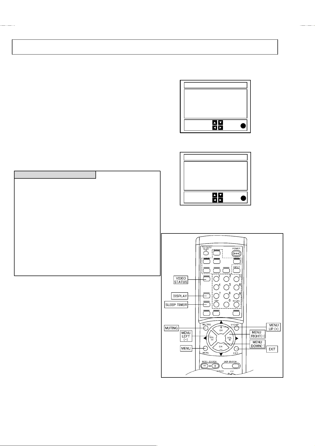
****
1) Press
SLEEP TIMER
MIN.
” is being displayed, press
key and, while the indication of “
DISPLAY
key and
on the remote control unit simultaneously.
2) The SERVICE MENU screen of Fig.1 is displayed.
3) While the SERVICE MENU is displayed, again simultaneously press
DISPLAY
the
VIDEO STATUS
and
keys to display the Fig.2 SYSTEM
CONSTANT screen.
4) Refer to the SYSTEM CONSTANT screen and check the setting items.
Where these differ, select the setting item with the MENU UP/DOWN
key and adjust the setting with the MENU LEFT/RIGHT keys. (The
letters of the selected item are displayed in yellow.)
5) After adjusting, release the MENU LEFT/RIGHT key to store the setting
value.
6) Press the
EXIT
key twice to return to the normal screen.
SLEEP TIMER 0
VIDEO STATUS
key
SERVICE MENU
SERVICE MENU
PICTURE SOUND
VIDEO STATUS
OTHERS
LOW LIGHT HIGH LIGHT
RF AFC
I2C BUS CTRL
SELECT BY
OPERATE BY EXIT BY
EX
IT
Fig.1
SYSTEM CONSTANT
SYSTEM CONSTANT
V-CHIP : YES
CAN V-CHIP : YES
***
MN1876476
SELECT BY
OPERATE BY EXIT BY
***
******
EX
IT
Fig.2
NAME OF REMOTE CONTROL KEY
(5) Receive channel setting
Refer to the OPERATING INSTRUCTIONS (USER'S GUIDE) and set
the receive channels (Channels Preset) as described.
(6) User settings
Check the user setting items according to Table 1.(page8 on AV-20240)
Where these do not agree, refer to the OPERATING INSTRUCTIONS
(USER'S GUIDE) and set the items as described.
(7) SERVICE MENU setting
Verify what to set in the SERVICE MENU, and set whatever is
necessary. (Fig.1) Refer to the SERVICE ADJUSTMENT for setting.
2
No. 51820
Page 3

■ DIFFERENCE PARTS LIST
PARTS LIST (TV)
SYMBOL
!!!!
No.
TV-20240
No.51520
(US&CA)
TV-20240
No.51520C
REMOTE CONTROL UNIT PARTS LIST (Page 59)
2AA023600 UR52EC1286A BATTERY COVER
EXPLODED VIEW PARTS LIST (Page 60)
11 CM43094-008-H
!
12 LC30491-002B-H
PARTS No.
(A US&A CA)
TV-20241
No.51688
(US&CA)
TV-20242
No.51820
CM43094-010-H
LC30491-004A-H
TV-20242
PARTS NAME DESCRIPTION
Not
interchangeable
JVC MARK
POWER KNOB
Not
interchangeable
↑
!
!
!
!
!
!
16 LC20197-003B-H
19 LC20198-003B-H
24 LC10256-002B-H
30 LP20324-002D LP20324-002F DOOR OPENER
32 LC10255-003C-H
33 LC20199-003C-H
35 LC20106-001B-A
LC20197-005A-H
LC20198-005A-H
LC10256-002C-H
LC10255-005A-H
LC20199-005A-H
LC20106-001D-A
CASSETTE FLAP
VTR KNOB
REAR COVER
FRONT CABINET
DOOR
POWER CORD CLAMP
PARTS LIST (VCR)
SYMBOL
!!!!
No.
TV-20240
No.51520
(US&CA)
TV-20240
No.51520C
CABINET AND CHASSIS ASSEMBLY<M2> (Page 65)
LP30247-001B LP30247-002B FRONT BRACKET
DEMOD BOARD ASSEMBLY<63> (Page 68)
PW1 L PA10050-01B SFC0A001A-H2 DEMOD PWB ASSY Interchangeable
MAIN BOARD ASSEMBLY<70> (Page 68, 73)
PW1 LPA10040-03B SFC-7001A-H2 SFC-7002A-H2
IC9001
C6001 QETN1CM-476 QETN1EM-476Z E CAPACITOR
MN18P76476BP-05
or MN1874876JM
PARTS No.
(A US&A CA)
TV-20241
MN1876476FA IC
(US&CA)
No.51688
TV-20242
No.51820
SFC-7003A-H2
PARTS NAME DESCRIPTION
MAIN BOARD ASSY
↑
↑
↑
↑
↑
↑
↑
Not
interchangeable
Not
interchangeable
↑
↑
PACKING PARTS LIST
SYMBOL
!!!!
!
!
No.
4 RM-C139-1C RM-C389-1H REMOCON UNIT
2 CP11613-A82-H LC10453-074A-H
7 LCT0316-001A-H LCT0614-001A-H
6 LCT0317-001A-H LCT0615-001A-H
TV-20240
No.51520
(US&CA)
(Page 75)
TV-20240
(A US&A CA)
No.51520C
PARTS No.
TV-20241
(US&CA)
No.51688
No. 51820
TV-20242
No.51820
LC10453-0A5A-H
LCT0999-001A-H
LCT1000-001A-H
PARTS NAME DESCRIPTION
Not
interchangeable
PACKING CASE
INST BOOK
INST BOOK
(Only CA Model)
↑
↑
↑
3
Page 4

JVC SERVICE & ENGINEERING COMPANY OF AMERICA
DIVISION OF JVC AMERICAS CORP.
Head office : 1700 Valley Road, Wayne, New Jersey 07470 (973)315-5000
East Coast : 10 New Maple Avenue, Pine Brook, New Jersey 07058 (973)396-1000
Midwest : 705 Enterprise St. Aurora, Illinois 605 04 (630)851-7855
West Coast: 5665 Corporate Avenue, Cypress, California 90630 (714)229-8011
Southwest : 10700 Hammerly, Suite 105, Houston,Texas 77043 (713)935-9331
Hawaii : 2969 Mapunapuna Place, Honolulu, Hawaii 96819 (808)833-5828
Southeast : 1500 Lakes Parkway, Lawrenceville, Georgia 30243 (770)339-2582
JVC CANADA INC.
Head office : 21 Finchdene Square Scarborough, Ontario M1X 1A7 (416)293-1311
Vancouver : 13040 Worster Court Richmond B.C. V6V 2B3 (604)270-1311
4
TV-20242-UCM
#610(010425)
VP 0105
DP1059
 Loading...