

Page 1
SERVICE MANUAL
HD DIGITAL TERRESTRIAL SET TOP BOX
YA22720051
TU-HD500A
STB
TABLE OF CONTENTS
1 PRECAUTION. . . . . . . . . . . . . . . . . . . . . . . . . . . . . . . . . . . . . . . . . . . . . . . . . . . . . . . . . . . . . . . . . . . . . . . . . 1-3
2 SPECIFIC SERVICE INSTRUCTIONS . . . . . . . . . . . . . . . . . . . . . . . . . . . . . . . . . . . . . . . . . . . . . . . . . . . . . . 1-4
3 DISASSEMBLY . . . . . . . . . . . . . . . . . . . . . . . . . . . . . . . . . . . . . . . . . . . . . . . . . . . . . . . . . . . . . . . . . . . . . . . 1-6
4 ADJUSTMENT . . . . . . . . . . . . . . . . . . . . . . . . . . . . . . . . . . . . . . . . . . . . . . . . . . . . . . . . . . . . . . . . . . . . . . . . 1-9
5 TROUBLESHOOTING . . . . . . . . . . . . . . . . . . . . . . . . . . . . . . . . . . . . . . . . . . . . . . . . . . . . . . . . . . . . . . . . . 1-10
COPYRIGHT © 2005 Victor Company of Japan, Limited
No.YA227
2005/1
Page 2
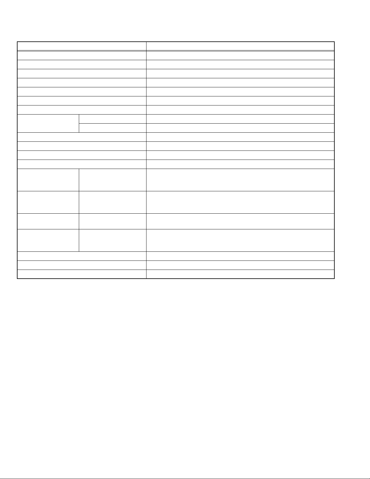
SPECIFICATION
Items Contents
Dimensions ( W × H × D ) 34.0cm × 7.0cm × 27.0cm
Mass (approx.) 2.6kg
Broadcasting System (Terrestrial) DVB-T / OFDM
RF System PAL
Video System PAL
Audio System (Digital) MPEG-1 layers 1 / 2 , MPEG-2 layers 2 , 32kHz / 44.1kHz / 48kHz
Teletext System Digital Teletext
Receiving Frequency VHF 174MHz to 230MHz
UHF 520MHz to 820MHz
Power Input AC100V to AC250V, 50Hz / 60Hz
Power Consumption 40W(Max) / 25W(Nominal) / 3W(standby)
Antenna Input (U/V Input) 75Ω, (PAL type) x1, IEC-Female connector
Loop Output (U/V Output) 75Ω, (PAL type) x1, IEC-Male connector
TV Output Composite Video
S-Video
SD Output Component Video
RGB Video
HD Output 1080i/720p/576p Video Y : 1V(p-p), 75Ω
HD VGA Output
Analog Audio Output 2.0V(rms), 10KΩ, stereo (RCA x2)
Digital Audio Output S/PDIF coaxial (RCA) × 1, S/PDIF optical (TOS Link) × 1
Remote Control Unit GTR300RBAJ10 (RM-C1050), (AA/R06 dry battery × 2)
1V(p-p) , 75Ω
Y : 1V(p-p) positive, 75Ω
C : 0.286V(p-p) (burst signal), 75Ω
Y/GS : 1V(p-p) , 75Ω
PB/B / PR/R : 0.7V(p-p) , 75Ω
1V(p-p) , 75Ω
PB / PR :0.7V(p-p), 75Ω
D-SUB 15-pin
RGB
0.7V(p-p) ,75Ω
VGA
640dot × 480dot
Design & specifications are subject to change without notice.
1-2 (No.YA227)
Page 3
SECTION 1
PRECAUTION
1.1 SAFETY PRECAUTIONS
(1) The design of this product contains special hardware,
many circuits and components specially for safety
purposes. For continued protection, no changes should be
made to the original design unless authorized in writing by
the manufacturer. Replacement parts must be identical to
those used in the original circuits. Service should be
performed by qualified personnel only.
(2) Alterations of the design or circuitry of the products should
not be made. Any design alterations or additions will void
the manufacturer's warranty and will further relieve the
manufacturer of responsibility for personal injury or
property damage resulting therefrom.
(3) Many electrical and mechanical parts in the products have
special safety-related characteristics. These
characteristics are often not evident from visual inspection
nor can the protection afforded by them necessarily be
obtained by using replacement components rated for
higher voltage, wattage, etc. Replacement parts which
have these special safety characteristics are identified in
the parts list of Service manual. Electrical components
having such features are identified by shading on the
schematics and by ( ) on the parts list in Service
manual. The use of a substitute replacement which does
not have the same safety characteristics as the
recommended replacement part shown in the parts list of
Service manual may cause shock, fire, or other hazards.
(4) Don't short between the LIVE side ground and
ISOLATED (NEUTRAL) side ground or EARTH side
ground when repairing.
Some model's power circuit is partly different in the GND.
The difference of the GND is shown by the LIVE : ( ) side
GND, the ISOLATED (NEUTRAL) : ( ) side GND and
EARTH : ( ) side GND.
Don't short between the LIVE side GND and ISOLATED
(NEUTRAL) side GND or EARTH side GND and never
measure the LIVE side GND and ISOLATED (NEUTRAL)
side GND or EARTH side GND at the same time with a
measuring apparatus (oscilloscope etc.). If above note will
not be kept, a fuse or any parts will be broken.
(5) If any repair has been made to the chassis, it is
recommended that the B1 setting should be checked or
adjusted (See B1 POWER SUPPLY check).
(6) The high voltage applied to the picture tube must conform
with that specified in Service manual. Excessive high
voltage can cause an increase in X-Ray emission, arcing
and possible component damage, therefore operation
under excessive high voltage conditions should be kept to
a minimum, or should be prevented. If severe arcing
occurs, remove the AC power immediately and determine
the cause by visual inspection (incorrect installation,
cracked or melted high voltage harness, poor soldering,
etc.). To maintain the proper minimum level of soft X-Ray
emission, components in the high voltage circuitry
including the picture tube must be the exact replacements
or alternatives approved by the manufacturer of the
complete product.
(7) Do not check high voltage by drawing an arc. Use a high
voltage meter or a high voltage probe with a VTVM.
Discharge the picture tube before attempting meter
connection, by connecting a clip lead to the ground frame
and connecting the other end of the lead through a 10kΩ
2W resistor to the anode button.
(8) When service is required, observe the original lead dress.
Extra precaution should be given to assure correct lead
dress in the high voltage circuit area. Where a short circuit
has occurred, those components that indicate evidence of
overheating should be replaced. Always use the
manufacturer's replacement components.
(9) Isolation Check (Safety for Electrical Shock Hazard)
After re-assembling the product, always perform an
isolation check on the exposed metal parts of the cabinet
(antenna terminals, video/audio input and output terminals,
Control knobs, metal cabinet, screw heads, earphone jack,
control shafts, etc.) to be sure the product is safe to operate
without danger of electrical shock.
a) Dielectric Strength Test
The isolation between the AC primary circuit and all metal
parts exposed to the user, particularly any exposed metal
part having a return path to the chassis should withstand a
voltage of 3000V AC (r.m.s.) for a period of one second. (.
. . . Withstand a voltage of 1100V AC (r.m.s.) to an
appliance rated up to 120V, and 3000V AC (r.m.s.) to an
appliance rated 200V or more, for a period of one second.)
This method of test requires a test equipment not generally
found in the service trade.
b) Leakage Current Check
Plug the AC line cord directly into the AC outlet (do not use
a line isolation transformer during this check.). Using a
"Leakage Current Tester", measure the leakage current
from each exposed metal part of the cabinet, particularly
any exposed metal part having a return path to the chassis,
to a known good earth ground (water pipe, etc.). Any
leakage current must not exceed 0.5mA AC (r.m.s.).
However, in tropical area, this must not exceed 0.2mA AC
(r.m.s.).
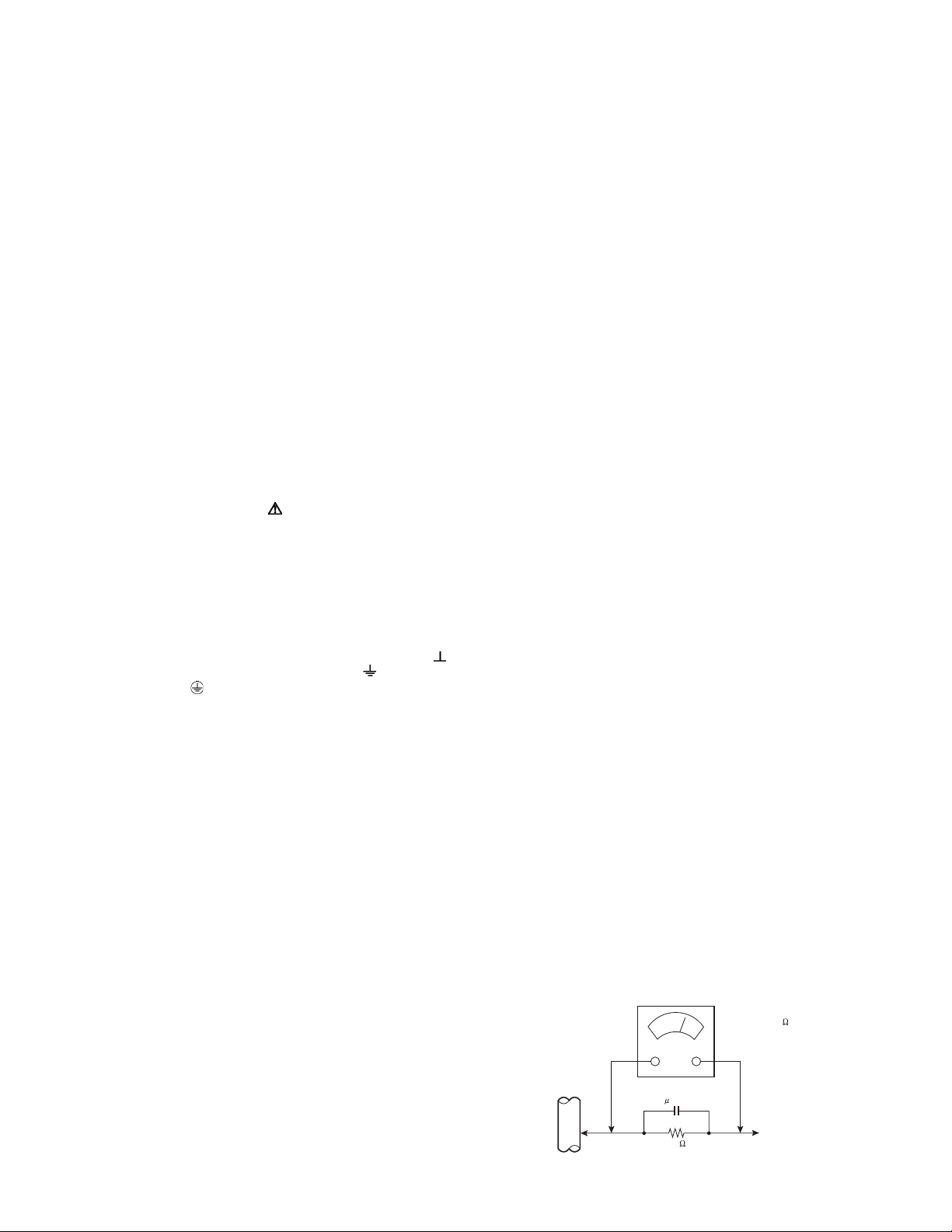
Alternate Check Method
Plug the AC line cord directly into the AC outlet (do not
use a line isolation transformer during this check.). Use
an AC voltmeter having 1000Ω per volt or more
sensitivity in the following manner. Connect a 1500Ω
10W resistor paralleled by a 0.15µF AC-type capacitor
between an exposed metal part and a known good earth
ground (water pipe, etc.). Measure the AC voltage
across the resistor with the AC voltmeter. Move the
resistor connection to each exposed metal part,
particularly any exposed metal part having a return path
to the chassis, and measure the AC voltage across the
resistor. Now, reverse the plug in the AC outlet and
repeat each measurement. Any voltage measured must
not exceed 0.75V AC (r.m.s.). This corresponds to
0.5mA AC (r.m.s.).
However, in tropical area, this must not exceed 0.3V AC
(r.m.s.). This corresponds to 0.2mA AC (r.m.s.).
AC VOLTMETER
(HAVING 1000 /V,
OR MORE SENSITIVITY)
0.15 F AC-TYPE
PLACE THIS PROBE
1500 10W
GOOD EARTH GROUND
ON EACH EXPOSED
ME TAL PAR T
(No.YA227)1-3
Page 4
SECTION 2
SPECIFIC SERVICE INSTRUCTIONS
2.1 INTRODUCTION
• TU-HD500A is a DVB-T set-top box capable of decoding MPEG coded source. It outputs CVBS, RGB and Y/C analog video and
left -right analog audio. TU-HD500A also has digital audio output.
• The tuner is capable of getting both digital broadcasts. The tuner is capable of receiving both VHF and UHF horizontal bands.
The tuning is available through the digitally controlled I2C bus (PLL).
2.2 FUNCTIONS
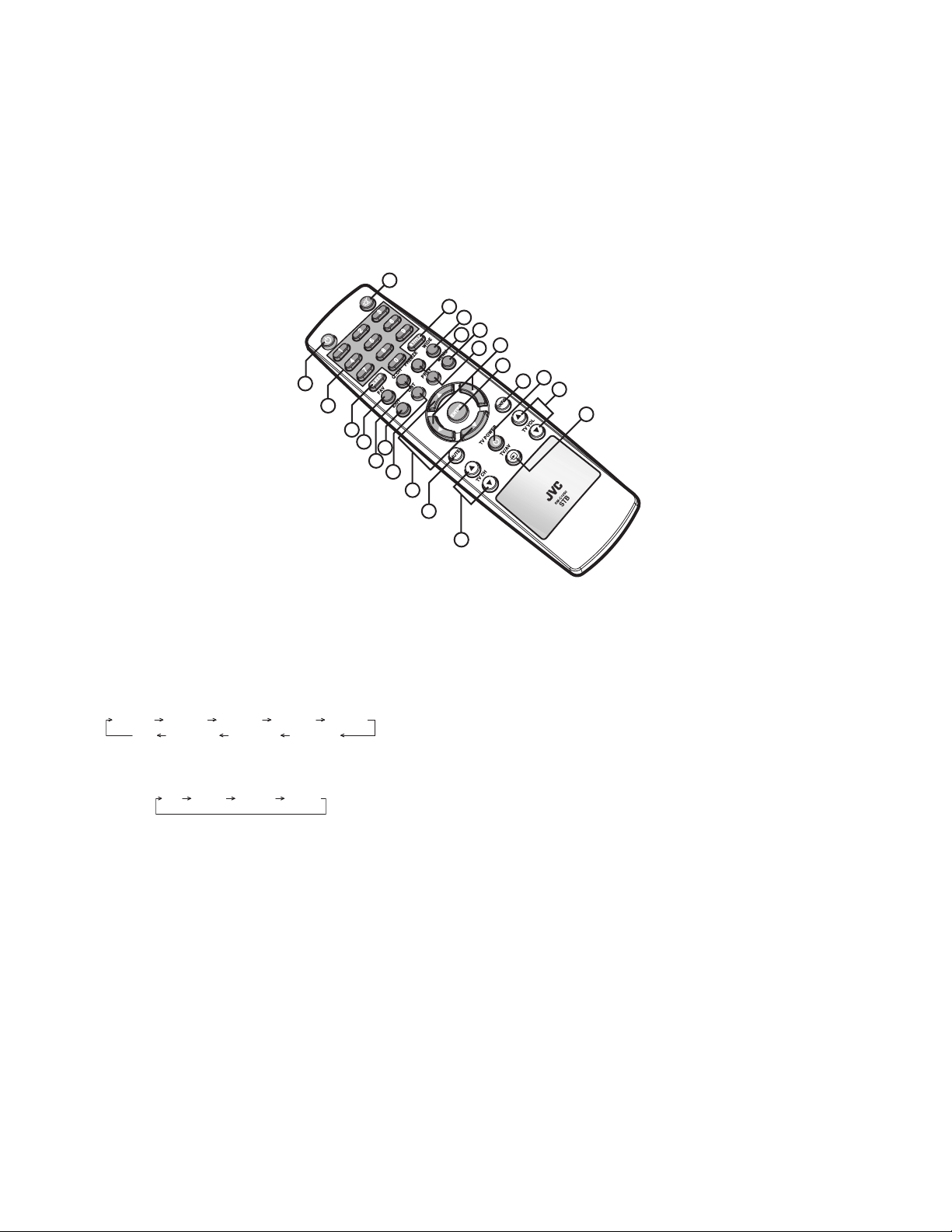
[REMOTE CONTROL UNIT]
1
2
17
3
4
6
5
7
1. POWER
Turn your HD-STB on or off.
2. 0-9 (Number)
Direct change the desired channel.
3. SLEEP
Press to adjustment the period of off time.
15min 30min 45min 60min 90min
Off 240min 180min 120min
4. FAV (Favorite)
Direct change the Favorite CH in the menu.
All Fav1 Fav2 Fav3
5. QUICK CH (Quick channel)
To quick memorized channel change.
6. EXIT
Quit the menu system.
7. LIST
Display the selected memorized channel list followed by
Favorite CH select.
You can direct select desired channel using CH [/], PR [/
] button.
8. CH [/] (Up/Down)
Change the channel Up or Down followed by memorized
channel.
9. INFO (Information)
Display current channel EPG information. You can see the
NOW and NEXT information. If you press INFO button again,
you can see the more detailed information.
10. ENTER
Select the current setting in the menu system.
16
15
13
14
11
12
10
22
9
21
20
8
18
19
11. PR [/] (Left / Right)
Change the program up or down. In the menu system, move
left or the cursor.
12. PREV (Previous channel)
Direct go to the previous watched channel.
13. MENU
Activate the menu system.
14. FREEZE
Freezing the picture for viewing with still image. Sound muting
is also activated.
15. WIDE
To picture aspect ratio change. It will change to 4:3PS 4:3LB
16:9 4:3PS.
(4:3 PS : 4:3 Pan and Scan / 4:3 LB : 4:3 Letter Box)
16. S.TITLE (Sub title)
Activate Sub title (Caption) display On / Off.
17. MUTE
Activate audio output muting for set-top box.
TV CONTROL SECTION
18. MUTE (Picture muting)
Activate Picture muting operation.
19. TV CH [/]
Change the TV analog channel Up or Down.
20. TV/AV (External Video Input Select)
Select the TV external video input.
21. TV VOL [/]
Change the TV Volume level Up or Down.
22. TV POWER
Turn On / Off the TV set.
1-4 (No.YA227)
Page 5

[FRONT]
1 2 3 4 5 6 78
1. POWER
Press to turn the HD-STB on or off.
2. Display panel
Display information to assist you in operating the HD-STB
successfully.
3. MENU
Activate the menu system.
4. EXIT
Quit the menu system.
5. ENTER
Select the items in the menu system.
[REAR]
9 11 12
10
20
2122
17 1819
6. PROGRAM (Up / Down)
"Press to change the program (This action changes the
programs stored in the favorite channels memory blocks)."
"Left or Right movement in the menu system."
7. CHANNEL (Up / Down)
"Press to change the channels (This action changes the
memorized channels in sequence)."
"Up or Down movement in the menu system."
8. Remote sensor
This HD-STB receives infrared remote signal from your remote
control. Do not block it.
141516
13
23
9. ANT IN terminal
Attach an external Antenna to this terminal.
10. LOOP OUT terminal
Use this terminal to feed RF signal to your TV or VCR for
analog reception.
11. TV composite video output terminal
Use this terminal with your TV video input.
12. S-VIDEO output terminal
Use this terminal with your TV S-video input.
13. AUDIO 1 output terminal (L/R analog stereo)
This terminal can be used with your TV analog audio input.
14. SD Y/Pb/Pr or SD RGB (SD component video) Output
terminal
Use this terminal with your TV equipped with component video
input. (SD or Normal)
15. HD Y/Pb/Pr (HD component video) output terminal
Use this terminal with your TV HD Component video input.
(HDTV only)
16. AUDIO 2 output terminal (L/R analog stereo)
This terminal can be used with your TV analog audio input.
17. Optical DIGITAL AUDIO (S/P DIF) output terminal
Use this terminal with A/V device equipped with optical digital
input.
18. Coaxial DIGITAL AUDIO (S/P DIF) output terminal
Use this terminal with A/V device equipped with coaxial digital
input.
19. HD VGA (HD component R.G.B/H.V) output terminal
Use this terminal with your TV HD VGA Video input. (only
HDTV equipped with VGA input or computer monitor).
20. MODE select switch
Set this switch in conjunction with DISPLAY switch according
to your TV display capability.
21. DISPLAY select switch
Set this switch in conjunction with MODE switch according to
your TV display capability.
22. RS-232C [Do not use]
Use this terminal for software upgrade purpose only.
23. Power cord
(No.YA227)1-5
Page 6

SECTION 3
DISASSEMBLY
3.1 DISASSEMBLY PROCEDURE
NOTE:
• Make sure that the power cord is disconnected from the outlet.
• Pay special attention not to break or damage the parts.
• When removing each board, remove the connectors as required. Taking notes of the connecting points (connector numbers)
makes service procedure manageable.
• Make sure that there is no bent or stain on the connectors before inserting, and firmly insert the connectors.
3.1.1 REMOVING THE TOP COVER
(1) Remove the 5 screws [A].
(2) Slightly spread the bottom of the TOP COVER.
(3) Shift the TOP COVER rearward and raise it upward to
remove it.
3.1.2 REMOVING THE FRONT PANEL / KNOBS
• Remove the TOP COVER.
• Remove the FLAT CABLE.
(1) Remove the 2 screws [B].
(2) Remove the 2 claws [C].
(3) Remove the FRONT PANEL.
(4) Remove the KNOBS.
• Pay special attention : Refer to ATTACHMENT CAUTION
FOR KNOBS.
3.1.3 REMOVING THE FRONT PWB
• Remove the TOP COVER.
(1) Remove the 5 screws [D].
(2) Remove the FRONT PWB.
3.1.4 REMOVING THE REAR PANEL
• Remove the TOP COVER.
(1) Remove the 3 screws [E].
(2) Withdraw the REAR PANEL back ward.
(3) Remove the REAR PANEL.
3.1.7 CHECKING THE PW BOARD
• To check the back side of the PW Board.
(1) Pull out the PW Board. (Refer to REMOVING THE MAIN
PWB).
(2) Erect the PW Board vertically so that you can easily check
the back side of the PW Board.
CAUTION:
• When erecting the PW Board, be careful so that there will be
no contacting with other PW Board.
• Before turning on power, make sure that the wire connector
is properly connected.
3.1.8 WIRE CLAMPING AND CABLE TYING
(1) Be sure to clamp the wire.
(2) Never remove the cable tie used for tying the wires
together.
Should it be inadvertently removed, be sure to tie the wires
with a new cable tie.
ATTACHMENT CAUTION FOR KONBS
FRONT PANEL
3.1.5 REMOVING THE MAIN PWB
• Remove the TOP COVER.
• Remove the REAR PANEL.
(1) Remove the 2 screws [F].
(2) Remove the MAIN PWB.
CAUTION:
If necessary, take off the wire clamp, connectors etc.
Be careful enough when developing a MAIN PWB.
3.1.6 REMOVING THE POWER PWB
• Remove the TOP COVER.
• Remove the connector of the POWER CORD.
(1) Remove the 4 screws [G].
(2) Remove the POWER PWB.
(3) Remove the INSULATOR.
1-6 (No.YA227)
KNOB
( / / / )
Width : Narrow
Width : Wide
KNOB
(MENU/EXIT/ENTER)
Width : Wide
Page 7

TOP COVER
A
(x1)
A
(x1)
A
(x3)
G
(x4)
POWER PWB
B
(x2)
See before page
MAIN PWB
F
(x2)
INSULATOR
FRONT PANEL
(x2)
C
KNOB
FRONT PWB
FRONT
FRONT PLATE
INSULATOR
POWER CORD
GASKET
D
(x5)
E
(x3)
BOTTOM COVER
REAR PANEL
(No.YA227)1-7
Page 8

3.2 REPLACEMENT OF CHIP COMPONENT
3.2.1 CAUTIONS
(1) Avoid heating for more than 3 seconds.
(2) Do not rub the electrodes and the resist parts of the pattern.
(3) When removing a chip part, melt the solder adequately.
(4) Do not reuse a chip part after removing it.
3.2.2 SOLDERING IRON
(1) Use a high insulation soldering iron with a thin pointed end of it.
(2) A 30w soldering iron is recommended for easily removing parts.
3.2.3 REPLACEMENT STEPS
1. How to remove Chip parts
2. How to install Chip parts
[Resistors, capacitors, etc.]
(1) As shown in the figure, push the part with tweezers and
alternately melt the solder at each end.
(2) Shift with the tweezers and remove the chip part.
[Transistors, diodes, variable resistors, etc.]
(1) Apply extra solder to each lead.
SOLDER
SOLDER
[Resistors, capacitors, etc.]
(1) Apply solder to the pattern as indicated in the figure.
(2) Grasp the chip part with tweezers and place it on the
solder. Then heat and melt the solder at both ends of the
chip part.
[Transistors, diodes, variable resistors, etc.]
(1) Apply solder to the pattern as indicated in the figure.
(2) Grasp the chip part with tweezers and place it on the
solder.
(3) First solder lead A as indicated in the figure.
(2) As shown in the figure, push the part with tweezers and
alternately melt the solder at each lead. Shift and remove
the chip part.
NOTE :
After removing the part, remove remaining solder from the
pattern.
1-8 (No.YA227)
A
B
C
(4) Then solder leads B and C.
A
B
C
Page 9

SECTION 4
ADJUSTMENT
This service manual does not describe ADJUSTMENT.
(No.YA227)1-9
Page 10

SECTION 5
TROUBLESHOOTING
This service manual does not describe TROUBLESHOOTING.
1-10 (No.YA227)
Page 11

Victor Company of Japan, Limited
AV & MULTIMEDIA COMPANY VIDEO DISPLAY CATEGORY 12, 3-chome, Moriya-cho, kanagawa-ku, Yokohama, kanagawa-prefecture, 221-8528, Japan
(No.YA227)
Printed in Japan
VPT
 Loading...