

Page 1

YA211200411
SERVICE MANUAL
DIGITAL TERRESTRIAL SET TOP BOX
TU-DB1SK
1TV32
4 65
7 98
0 AV
MENU
TV/DTV
OK
BACK
P
TV
WIDE GUIDESUB TITLE
TOP MENU
STB
TABLE OF CONTENTS
1 PRECAUTION. . . . . . . . . . . . . . . . . . . . . . . . . . . . . . . . . . . . . . . . . . . . . . . . . . . . . . . . . . . . . . . . . . . . . . . . . 1-3
2 SPECIFIC SERVICE INSTRUCTIONS . . . . . . . . . . . . . . . . . . . . . . . . . . . . . . . . . . . . . . . . . . . . . . . . . . . . . . 1-4
3 DISASSEMBLY . . . . . . . . . . . . . . . . . . . . . . . . . . . . . . . . . . . . . . . . . . . . . . . . . . . . . . . . . . . . . . . . . . . . . . . 1-6
4 ADJUSTMENT . . . . . . . . . . . . . . . . . . . . . . . . . . . . . . . . . . . . . . . . . . . . . . . . . . . . . . . . . . . . . . . . . . . . . . . . 1-9
5 TROUBLESHOOTING . . . . . . . . . . . . . . . . . . . . . . . . . . . . . . . . . . . . . . . . . . . . . . . . . . . . . . . . . . . . . . . . . 1-10
COPYRIGHT © 2004 Victor Company of Japan, Limited
No.YA211
2004/11
Page 2
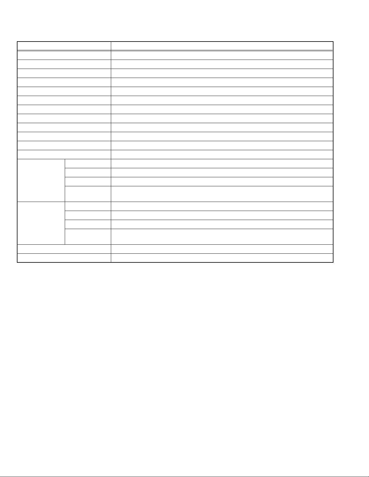
SPECIFICATION
Items Contents
Dimensions ( W × H × D ) 28.0cm × 4.0cm × 18.5cm
Mass 1.3kg
Broadcasting System DVB-T 2k & 8k
RF System PAL
Video System PAL
Audio System MPEG Layer I & II , 32kHz / 44.1kHz / 48kHz , Single / Dual channels , Stereo & joint stereo
Teletext System Digital Teletext
Channel Memory Number 200ch
Channel Coverage 474MHz to 858MHz
Power Requirements DC6V, AC adaptor : AC100V to AC240V, 50Hz / 60Hz
Antenna Input 75Ω unbalanced, PAL type × 1 (5V DC active antenna supply)
TV Output 75Ω unbalanced, PAL type × 1 (Loop through)
Video 1V (p-p) , 75Ω
TV(SCART-1)
Terminal
(Input/Output)
VCR(SCART-2)
Terminal
(Input/Output)
Digital Audio Output SPDIF coaxial × 1
Remote Control Unit VE-30031949 (RM-C1890S), (AA/R06 dry battery × 2)
Design & specifications are subject to change without notice.
Audio 500mV (rms) (-4dBs), 10kΩ min
RGB / Video 1V (p-p) , 75Ω
S-Video
RGB / Video 1V (p-p) , 75Ω
S-Video
Y : 1V (p-p) positive, 75Ω
C : 0.286V (p-p) (burst signal), 75Ω
Video 1V (p-p) , 75Ω
Audio 500mV (rms) (-4dBs), 10kΩ min
Y : 1V (p-p) positive, 75Ω
C : 0.286V (p-p) (burst signal), 75Ω
1-2 (No.YA211)
Page 3

SECTION 1
PRECAUTION
1.1 SAFETY PRECAUTIONS
(1) The design of this product contains special hardware and many circuits and components specially for safety purposes. For
continued protection, no changes should be made to the original design unless authorized in writing by the manufacturer.
Replacement parts must be identical to those used in the original circuits. Service should be performed by qualified personnel
only.
(2) Alterations of the design or circuitry of the product should not be made. Any design alterations or additions will void the
manufacturer's warranty and will further relieve the manufacturer of responsibility for personal injury or property damage
resulting therefrom.
(3) Many electrical and mechanical parts in the product have special safety-related characteristics. These characteristics are often
not evident from visual inspection nor can the protection afforded by them necessary be obtained by using replacement
components rated for higher voltage, wattage, etc. Replacement parts which have these special safety characteristics are
identified in the Parts List of Service Manual. Electrical components having such features are identified by shading on the
schematics and by ( ) on the Parts List in the Service Manual. The use of a substitute replacement which does not have the
same safety characteristics as the recommended replacement part shown in the Parts List of Service Manual may cause shock,
fire, or other hazards.
(4) The leads in the products are routed and dressed with ties, clamps, tubing’s, barriers and the like to be separated from live parts,
high temperature parts, moving parts and / or sharp edges for the prevention of electric shock and fire hazard. When service is
required, the original lead routing and dress should be observed, and it should be confirmed that they have been returned to
normal, after re-assembling.
WARNING
(1) The equipment has been designed and manufactured to meet international safety standards.
(2) It is the legal responsibility of the repairer to ensure that these safety standards are maintained.
(3) Repairs must be made in accordance with the relevant safety standards.
(4) It is essential that safety critical components are replaced by approved parts.
(5) If mains voltage selector is provided, check setting for local voltage.
(No.YA211)1-3
Page 4
SECTION 2
SPECIFIC SERVICE INSTRUCTIONS
2.1 INTRODUCTION
• TU-DB1SK is a DVB-T set-top box capable of decoding MPEG coded source. It outputs CVBS, RGB and Y/C analog video and left
-right analog audio. TU-DB1SK also has digital audio output.
• The tuner is capable of getting both digital broadcasts. The tuner is capable of receiving both UHF horizontal band.
The tuning is available through the digitally controlled I2C bus (PLL).
2.2 FUNCTIONS
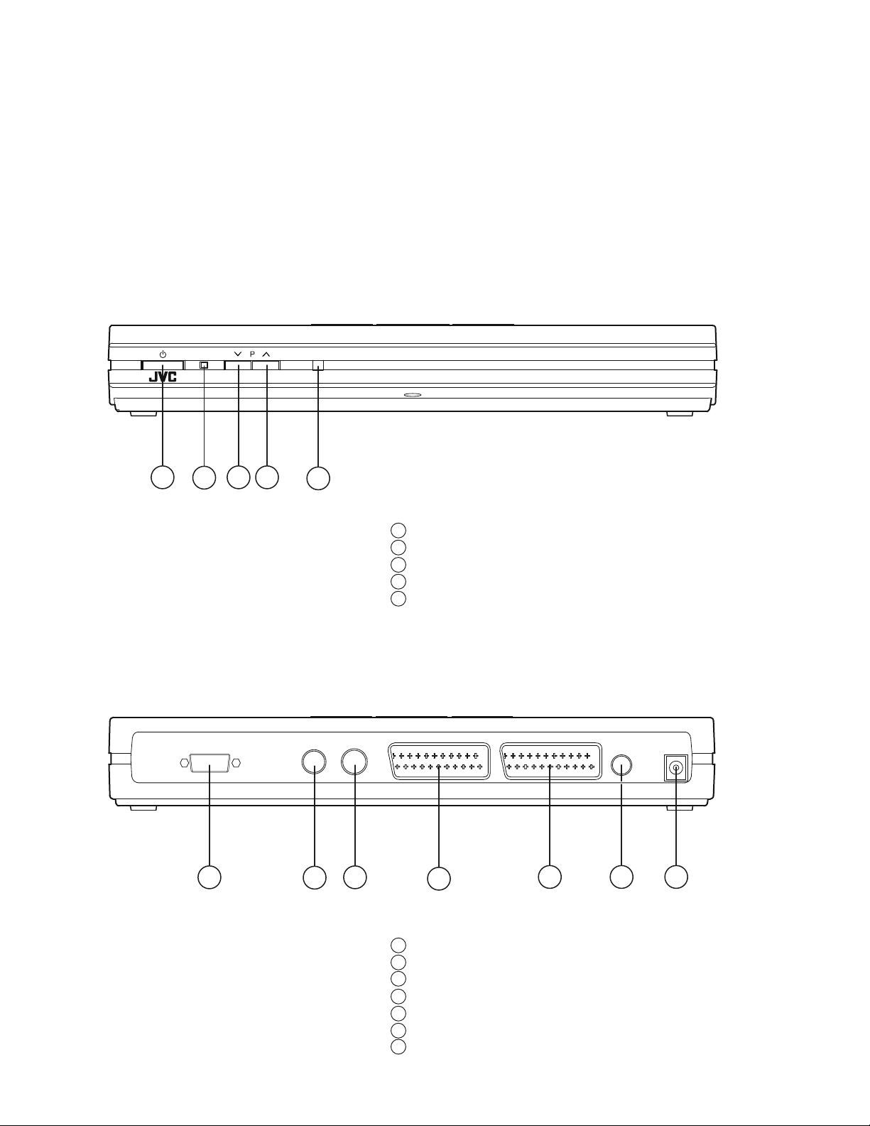
[FRONT]
[REAR]
1
3 4
2
5
1 Standby button(Power)
2 Power Indicator
3 Program up button
4 Program down button
5 REMOTE CONTROL UNIT Sensor
RS 232 TV OUT ANTENNA TV VCR SPDIF 6V DC
1
3
2
4
5 6 7
1-4 (No.YA211)
1 RS 232 Terminal
2 TV Output
3 Antenna Terminal
4 TV (Scart-1) Terminal (21-pin Euro connector)
5 VCR (Scart-2) Terminal (21-pin Euro conector)
6 SPDIF Terminal
7 DC 6V Input Terminal
Page 5

2.3 21-PIN EURO CONNECTOR (SCART SOCKET) : PL201 / PL601
[Pin assignment]
20 18 16 14 12 10 8 6 4 2
21 19 17 15 13 11 9 7 5 3 1
Pin
PL201 : TV SCART SOCKET PL601 : VCR SCART SOCKET
Description Description
1 Audio Right Output Audio Right Output
2 Audio Right Input Audio Right Input
3 Audio Left Output Audio Left Output
4GND GND
5GND GND
6 Audio Left Input Audio Left Input
7 BLUE Output BLUE Output
8 Function Switching Output Function Switching Input
9GND GND
10 Not connected No Connection
11 GREEN Output GREEN Output
12 Not connected No Connection
13 GND GND
14 GND GND
15 RED Output / C Output RED Output / C Output
16 Fast Blanking Output No Connection
17 GND GND
18 GND GND
19 CVBS Output / Y Output CVBS Output / Y Output
20 CVBS Input CVBS Input
21 GND GND
(No.YA211)1-5
Page 6

SECTION 3
DISASSEMBLY
3.1 DISASSEMBLY PROCEDULE
3.1.1 TOP COVER
(1) Unplug the connecting the AC adaptor.
(2) Remove the 4 the Rubber Foot .
(3) Remove the 5 screws [A] .
(4) Withdraw the TOP COVER.
3.1.2 MAIN PWB
• Take out the TOP COVER.
(1) Remove the 1 screw [B] .
(2) Slightly raise the both sides of the MAIN PWB by hand and
withdraw the MAIN PWB backward.
[CAUTION]
If necessary, take off the wire clamp, connectors etc.
Be careful enough when developing a MAIN PWB.
3.1.3 FRONT CONTROL PWB
• Take out the TOP COVER.
(1) Remove the 2 screws [C].
(2) Remove the FRONT CONTROL PWB.
3.1.4 DAUGHTER PWB
• Take out the TOP COVER.
(1) Remove the 2 screws [D].
(2) Remove the DAUGHTER PWB.
3.1.6 CHECKING THE PW BOARD
• To check the back side of the PW Board.
(1) Pull out the PW Board. (Refer to REMOVING THE MAIN
PWB).
(2) Erect the PW Board vertically so that you can easily check
the back side of the PW Board.
[CAUTION]
• When erecting the PW Board, be careful so that there will be
no contacting with other PW Board.
• Before turning on power, make sure that the wire connector
is properly connected.
3.1.7 WIRE CLAMPING AND CABLE TYING
(1) Be sure to clamp the wire.
(2) Never remove the cable tie used for tying the wires
together.
Should it be inadvertently removed, be sure to tie the wires
with a new cable tie.
3.1.5 BACK COVER
• Take out the TOP COVER.
(1) Raise up the both sides and withdraw the BACK COVER.
1-6 (No.YA211)
Page 7

FRAME L
AC ADAPTOR
TOP COVER
FRAME R
BACK COVER
MAIN PWB
LED LENS
LED FRAME
D
(x2)
PROGRAM
DOWN/UP
BUTTONS
DAUGHTER PWB
B
(x1)
C
(x2)
FRONT CONTROL
PWB
SENSOR LENS
SENSOR LENS
HOLDER
BOTTOM COVER
STANDBY
BUTTON
A
(x2)
RUBBER FOOT
(x2)
A
(x2)
A
(x1)
RUBBER FOOT
(x2)
(No.YA211)1-7
Page 8

3.2 REPLACEMENT OF CHIP COMPONENT
3.2.1 CAUTIONS
(1) Avoid heating for more than 3 seconds.
(2) Do not rub the electrodes and the resist parts of the pattern.
(3) When removing a chip part, melt the solder adequately.
(4) Do not reuse a chip part after removing it.
3.2.2 SOLDERING IRON
(1) Use a high insulation soldering iron with a thin pointed end of it.
(2) A 30w soldering iron is recommended for easily removing parts.
3.2.3 REPLACEMENT STEPS
1. How to remove Chip parts
2. How to install Chip parts
[Resistors, capacitors, etc.]
(1) As shown in the figure, push the part with tweezers and
alternately melt the solder at each end.
(2) Shift with the tweezers and remove the chip part.
[Transistors, diodes, variable resistors, etc.]
(1) Apply extra solder to each lead.
SOLDER
SOLDER
[Resistors, capacitors, etc.]
(1) Apply solder to the pattern as indicated in the figure.
(2) Grasp the chip part with tweezers and place it on the
solder. Then heat and melt the solder at both ends of the
chip part.
[Transistors, diodes, variable resistors, etc.]
(1) Apply solder to the pattern as indicated in the figure.
(2) Grasp the chip part with tweezers and place it on the
solder.
(3) First solder lead A as indicated in the figure.
(2) As shown in the figure, push the part with tweezers and
alternately melt the solder at each lead. Shift and remove
the chip part.
NOTE :
After removing the part, remove remaining solder from the
pattern.
1-8 (No.YA211)
A
B
C
(4) Then solder leads B and C.
A
B
C
Page 9

SECTION 4
ADJUSTMENT
This service manual does not describe ADJUSTMENT.
(No.YA211)1-9
Page 10

SECTION 5
TROUBLESHOOTING
This service manual does not describe TROUBLESHOOTING.
1-10 (No.YA211)
Page 11

Victor Company of Japan, Limited
AV & MULTIMEDIA COMPANY VIDEO DISPLAY CATEGORY 12, 3-chome, Moriya-cho, kanagawa-ku, Yokohama, kanagawa-prefecture, 221-8528, Japan
(No.YA211)
Printed in Japan
VPT
 Loading...