

Page 1
SERVICE MANUAL
FAN UNIT
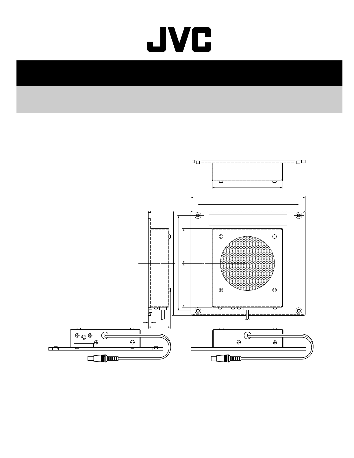
TS-C01FANG
TS-C01FANG
BASIC CHASSIS
CH
TO FAN UNIT
107
174
154
MODEL No. IF-C01FANG
146
160
67.5 52.5
4
38
FAN UNIT BFAN UNIT A
Total Mass : 1.1 k˝
(Unit : mm)
CONTENTS
a INSTRUCTIONS.......................................................................................................................................2
a PARTS LIST .............................................................................................................................................3
COPYRIGHT © 2002 VICTOR COMPANY OF JAPAN, LTD.
No. 52040
May 2002
Page 2
TS-C01FANG
TS-C01 FANG
Instructions for Assembly
WARNING
•
Only attach to the JVC specified PDP Monitor.
Attachment to other objects could result in fire or damage.
•
Only use the screws provided for assembly of this unit.
Failure to do so could cause the Monitor to collapse or fall, resulting in injury or damage.
•
Only use the screws provided.
Failure to do so could cause the screws to interfere with the circuits, resulting in electric shock or damage to the monitor.
•
Only use the wire clamp provided to keep the electric wires in place.
Failure to do so could result in fire or damage when attaching to a wall unit.
•
Plug in the DC plug provided into its corresponding DC jack.
Failure to do so could result in fire or damage due to inappropriate operation.
•
Do not cover the ventilation areas of the Fan Unit and PDP Monitor.
Failure to do so could result in fire and damage due to insufficient ventilation.
•
Clean the ventilation areas of both the Fan Unit and PDP Monitor.
Operation when the unit is covered in dust could result in fire or damage.
Fan Unit
Parts List
ATTENTION
During assembly, be careful not to touch metal edges.
q Fan Unit A x 1 w Fan Unit B x 1
DC plug
e Screw x 8 r Wire Clamp X 10
Non output terminal
DC plug
(Black)
Length: 12mm
Output terminal
DC jack
S tight screw
Assembly, Set Up Precautions
© 2002 VICTOR COMPANY OF JAPAN, LIMITED
VICTOR COMPANY OF JAPAN, LIMITED
• For more details, consult your local dealer.
Printed in Japan
LC21141-001A
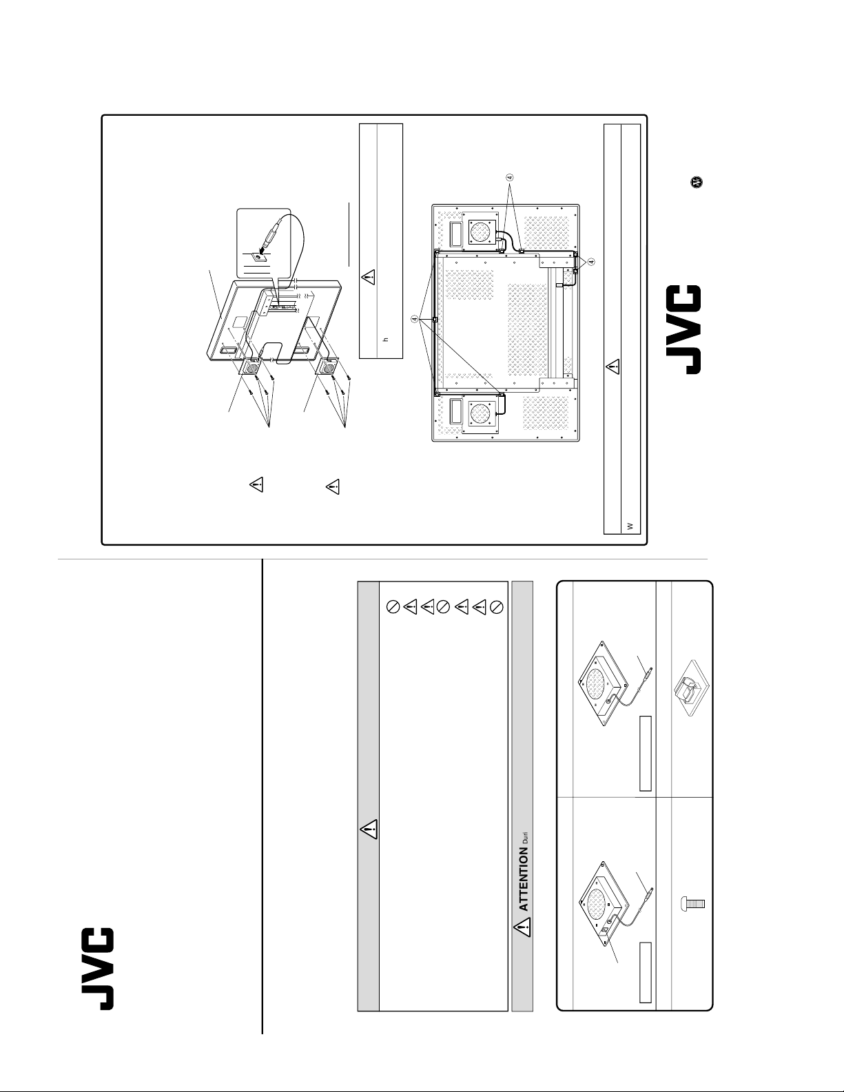
How to assemble
(Install the Fan Units before attaching in the wall or ceiling units.)
1. Using four black screws provided e, affix Fan Unit A q to the rear right side of the PDP Monitor, as illustrated below.
2. Using four black screws provided e, affix Fan Unit B w to the rear left side of the PDP Monitor, as illustrated below.
3. Plug the DC plug for Fan Unit A q into the OPTION terminal for the PDP Monitor.
4. Plug the DC plug for Fan Unit B w into the DC jack for Fan Unit A, labeled
“TO FAN UNIT”.
5. Peel off the sticker attached to the wire clamp r, and attach to the PDP Monitor to fix the wires in place, attach to
the spots illustrated below.
6. Turn the PDP Monitor on and confirm that the fans are operating.
PDP Monitor
OPTION terminal
PDP Monitor
Fan Unit A
q
Fan Unit B
w
ATTENTION
When using in the upright position (illustrated above), ensure Fan
Unit A, located on the rear right of the PDP Monitor, is facing upward.
Attach using the black
screws provided
e
Upright position.
ATTENTION
When attaching on to a wall or ceiling unit, be careful that the wires do not get tangled and that the DC plug does not come loose.
Attach using the black
screws provided
e
INSTRUCTIONS
2 No. 52040
Page 3

PARTS LIST
4
*
0
DC PLUG
1. OUTER –
2. CENTER +
FAN +
FAN –
DC OUT –
DC OUT +
DC IN –
DC IN +
DC JACK (PIN
DC JACK (OUTER
RED
BLACK
TS-C01FANG
DC PLUG
1. OUTER –
)
)
2. CENTER +
FAN +
FAN –
DC IN –
DC IN +
RED
BLACK
(
8
TO FAN UNIT
1
7
FAN UNIT A FAN UNIT B
3
5
@
%
MODEL No. IF-C01FANG
^
)
9
2
& 6 $ !
PARTS LIST
!
Ref.No. Part No. Part Name Description Local
1 YAC3608-001 FAN CASE For FAN UNIT A
2 YAC3608-002 FAN CASE For FAN UNIT B
3 YAC3616-001 FAN BASE (X 2)
4 YAC4570-001 FAN COVER (X 2)
5 YAC4574-001 DC JACK BKT
6 YDD4974-002 FAN PWB ASS’Y (X 2)
7 YWA1221-00A DC JACK
8 YAB4571-001 DC PLUG CORD For FAN UNIT A
9 YAB4571-002 DC PLUG CORD For FAN UNIT B
10 YAM4572-001 STUD (X 8)
11 ASB-320 STUD (X 4)
12 KF-21 CORD BUSH (X 2)
14 QYSDST3005M SCREW (X 8)
15 QYSPSPD3030Z SCREW (X 8)
16 QYSBSB4012M SCREW (X 8)
17 QRG039J-560 OM R (X 2) 56Ø 3W J
18 QAR0238-002 FAN (X 2)
19 YAA4537-001 LABEL
20 LC41402-002A CAUTION LABEL (X 2)
LC21141-001 INST BOOK
KAJ3613-001 PACKING CASE
LC32507-002A CARTON LABEL
No. 52040 3
Page 4

VICTOR COMPANY OF JAPAN, LIMITED
HOME AV NETWORK BUSINESS UNIT 12, 3-chome, Moriya-cho, kanagawa-ku, Yokohama, kanagawa-prefecture, 221-8528, Japan
TS-C01FANG
Printed in Japan
VP0205
SW
 Loading...