

Page 1

E-1
TK-C1480B
TK-C1481B
INSTRUCTIONS
COLOUR VIDEO CAMERA
BF
LOOK
C
O
L
O
R
VIDEO
C
A
M
E
R
A
DIGITAL
∞
LWT0064-001A
(CD-ROM)
Page 2

E-2
IMPORTANT SAFEGUARDS
PORTABLE CART WARNING
(symbol provided by RETAC)
S3125A
1. Read all of these instructions.
2. Save these instructions for later use.
3. All warnings on the product and in the operating instructions should be adhered to.
4. Unplug this appliance system from the wall outlet before cleaning. Do not use liquid cleaners
or aerosol cleaners. Use a damp cloth for cleaning.
5. Do not use attachments not recommended by the appliance manufacturer as they may
cause hazards.
6. Do not use this appliance near water - for example, near a bathtub, washbowl, kitchen
sink, or laundry tub, in a wet basement, or near a swimming pool, etc.
7. Do not place this appliance on an unstable cart, stand, or table. The
appliance may fall, causing serious injury to a child or adult, and
serious damage to the appliance.
Use only with a cart or stand recommended by the manufacturer, or
sold with the appliance. Wall or shelf mounting should follow the
manufacturer’s instructions, and should use a mounting kit approved
by the manufacturer. An appliance and cart combination should be
moved with care.
Quick stops, excessive force, and uneven surfaces may cause the
appliance and cart combination to overturn.
8. Slots and openings in the cabinet and the back or bottom are pro-vided for ventilation,
and to insure reliable operation of the appliance and to protect it from overheating, these
openings must not be blocked or covered. The openings should never be blocked by
placing the appliance on a bed, sofa, rug, or other similar surface.
This appliance should never be placed near or over a radiator or heat register. This appliance should not be placed in a built-in installation such as a bookcase unless proper
ventilation is provided.
9. This appliance should be operated only from the type of power source indicated on the
marking label. If you are not sure of the type of power supplied to your home, consult your
dealer or local power company. For appliance designed to operate from battery power,
refer to the operating instructions.
10. This appliance system is equipped with a 3-wire grounding type plug (a plug having a
third (grounding) pin). This plug will only fit into a grounding-type power outlet. This is a
safety feature. If you are unable to insert the plug into the outlet, contact your electrician
to replace your obsolete outlet. Do not defeat the safety purpose of the grounding plug.
11. For added protection for this product during a lightning storm, or when it is left unattended
and unused for long periods of time, unplug it form the wall outlet and disconnect the
antenna or cable system. This will prevent damage to the product due to lightning and
power-line surges.
12. Do not allow anything to rest on the power cord. Do not locate this appliance where the
cord will be abused by persons walking on it.
Page 3

E-3
13. Follow all warnings and instructions marked on the appliance.
14. Do not overload wall outlets and extension cords as this can result in fire or electric shock.
15. Never push objects of any kind into this appliance through cabinet slots as they may
touch dangerous voltage points or short out parts that could result in a fire or electric
shock. Never spill liquid of any kind on the appliance.
16. Do not attempt to service this appliance yourself as opening or removing covers may
expose you to dangerous voltage or other hazards. Refer all servicing to qualified service
personnel.
17. Unplug this appliance from the wall outlet and refer servicing to qualified service personnel under the following conditions:
a. When the power cord or plug is damaged or frayed.
b. If liquid has been spilled into the appliance.
c. If the appliance has been exposed to rain or water.
d. If the appliance does not operate normally by following the operating instructions. Ad-
just only those controls that are covered by the operating instructions as improper
adjustment of other controls may result in damage and will often require extensive
work by a qualified technician to restore the appliance to normal operation.
e. If the appliance has been dropped or the cabinet has been damaged.
f. When the appliance exhibits a distinct change in performance - this indicates a need
for service.
18. When replacement parts are required, be sure the service technician has used replacement parts specified by the manufacturer that have the same characteristics as the original part. Unauthorized substitutions may result in fire, electric shock, or other hazards.
19. Upon completion of any service or repairs to this appliance, ask the service technician to
perform routine safety checks to determine that the appliance is in safe operating
condition.
Page 4

E-4
WARNING:
TO REDUCE THE RISK OF FIRE OR
ELECTRIC SHOCK, DO NOT
EXPOSE THIS APPLIANCE TO RAIN
OR MOISTURE.
Due to design modifications, data given in this
instruction book are subject to possible change
without prior notice.
AVERTISSEMENT:
POUR EVITER LES RISQUES
D’INCENDIE OU D’ELECTROCUTION, NE PAS EXPOSER
L’APPAREIL A L’HUMIDITE OU A LA
PLUIE.
Safety Precautions
Page 5

E-5
Thank you for purchasing this product.
(These instructions are for TK-C1480BE and TK-C1481BEG)
Before beginning to operate this unit, please read the instruction manual
carefully in order to make sure that the best possible performance is obtained.
CONTENTS
INTRODUCTION
Features ...............................................................................................................................6
Operating Precautions .........................................................................................................7
Controls, Connectors and Indicators ...................................................................................8
CONNECTION/INSTALLATION
RM-P2580 System............................................................................................................. 12
Procedures ........................................................................................................................14
Mounting the lens ..............................................................................................................15
Installing the ferrite core .................................................................................................... 16
Connections on the back ................................................................................................... 16
Mounting the camera .........................................................................................................18
Lens adjustment ................................................................................................................20
Back focus adjustment ...................................................................................................... 21
Auto white balance control adjustment .............................................................................22
MENU SETTING
Setting the menu ...............................................................................................................23
The flow of menu screen ...................................................................................................24
SYNC ADJUST Screen .....................................................................................................26
ALC SETTINGS Screen ....................................................................................................26
VIDEO ADJUST Screen ....................................................................................................30
MODE SELECT Screen ....................................................................................................31
MOTION DETECT Screen ................................................................................................32
COMMUNICATION Screen ...............................................................................................33
MAINTENANCE Screen ....................................................................................................33
FACTORY SETTINGS Screen ..........................................................................................33
BLC EDITTING Screen .....................................................................................................34
Manual Adjustment of White Balance ...............................................................................35
CAMERA TITLE Setting .................................................................................................... 36
Setting the MOTION DETECT Function ...........................................................................37
White spot compensation ..................................................................................................38
OTHERS
Specifications..................................................................................................................... 39
Page 6

E-6
A new DSP (Digital Signal Processor)
features a Extended Dynamic Range
(ExDR) and enables to shoot both bright
and dark locations.
The use of a new CCD with a SENSE UP
(X32) function realized the minimum
luminous flux density for subject of 0.6 lx
(F1.2, 50%, AGC 20dB) and 0.019 lx (at
slow shutter).
A motion detector function detects the
motion inside an image and emits alarm
signals.
The equipped Y/C terminals and RS-
422A/RS-485 terminals allow intended
compatibility with diversified systems.
Electronic zoom
The 10x electronic zoom allows
monitoring in far greater detail.
Features
Before starting an important recording,
be sure to perform a test recording in
order to confirm that a normal
recording is possible.
We do not accept liability for the loss of
a recording in the case of it becoming
impossible to record due to a problem
in the video camera, VCR or video tape.
We do not accept liability for any
damage to the camera in cases where
it is dropped because of bad installation
due to failure to observe the installation
instructions correctly. Please be careful
when installing the camera.
The motion detector is not a feature
which prevents theft, fire, etc. Even if
an accident should occur resulting in
damage, we do not accept any liability.
INTRODUCTION
Characters and symbols used in this instruction manual.
CAUTION : Cautionary notes concerning operation of the unit.
MEMO : Reference such as restrictions of features, etc.
: Reference page or item.
Page 7

E-7
● To save energy, when it is not being used
turn the system’s power off.
● This camera has been designed for indoor
use. When you use it outdoors, be sure
to use a housing or the like.
● Do not install or use the camera in the
following places.
• In a place exposed to rain or moisture.
• In a place with vapor or oil soot, for
example in a kitchen.
• When the ambient temperature rises
above or falls below the acceptable
range (from –10°C to 50°C).
• Near a source of radiation, X-rays,
strong radio waves or magnetism.
• In a place subject to vibration.
• In a place with excessive dirt.
● If this camera and the cables connected
to this camera are used where there are
strong electromagnetic waves or where
there is magnetism present, for example
near a radio or TV transmitter, power
transformer or an electric motor, the picture
may produce noise and the colours may
be affected.
● This camera incorporates an AGC circuit.
As a result, when it is used under low light
conditions, the camera sensitivity is
automatically boosted and the picture may
look uneven. However, this is not a
malfunction.
● While the AGC is activated, if a transceiver
which causes strong electromagnetic wave
is at close distance, the picture might suffer
from beat.
So please use the camera more than three
meters from such transceivers.
● When this camera is used in the ATW
mode, the recorded colours may be slightly
different from the actual colours due to the
operational principles of the auto-tracking
white balance circuit. However, this is not
a malfunction.
Operating Precautions
● If a high-intensity object (such as a lamp)
is shot, the image on the screen may have
vertical lines (smear) or blur (blooming)
at its periphery. This is a characteristic of
the CCD, and is not a defect.
● Observe the following when carrying out
camera maintenance.
• Turn the power OFF before proceeding
to carry out maintenance.
If it is contaminated seriously, clean the
contaminated part with a cloth (or a
tissue) which has been soaked in a
solution of water and a neutral detergent.
● The unit is to be powered by a DC 12 V or
an AC 24 V power supply. (TK-C1480BE)
The AC 24 V power supply should conform
to the following: Isolated power supply only
TK-C1481BEG Connect the power cable
to the commercial power supply of 230V.
● Caution for operating the video iris lens.
If the video iris lens is set to an extremely
low level, a malfunction – such as the
hunting phenomenon where the iris opens
and closes involuntary – can occur.
In such a case, first set the “LEVEL”
potentiometer on the lens to the H position
(iris open), and then adjust it to an optimum
level.
● The cable stopper on the terminal block
can come off sometimes. Therefore, be
sure to take enough time and fix the cable
securely.
● When a highly bright subject is shot,
sometimes undulations can be observed
on the vertical lines of the subject.
However, this phenomenon is peculiar to
the unit and is not a sign of malfunction.
● The beat may sometimes appear on the
screen if gain is raised when the line lock
is in use, but the phenomenon takes place
due to the fluctuation of power frequency
and is not a malfunction.
Page 8

E-8
INTRODUCTION
1
Lens mount
To attach the lens.
This is applicable to both C-mount lenses
and CS-mount lenses.
2
Backfocus adjustment ring
Adjusting the back focus during lens
installation.
When readjustment is required, loosen
the locking screw
3
by turning it
counterclockwise and turn the back focus
adjustment ring 2.
After the adjustment, tighten the locking
screw
3
again.
3
[BF LOCK] Back focus locking screw
This serves to fix the back focus-adjusting
ring.
4
Camera-mounting bracket
The bracket has been attached on the
bottom of the camera before shipment. It
can also be attached on the top
according to the circumstance.
To re-attach the bracket use the threaded
holes at the top, with the camera
mounting bracket locking screws
7
.
5
Camera-mounting screw hole (1/4
inch)
Use this hole when mounting
the camera onto a fixer, pan/
tilt unit, and the like. (Use a
screw shorter than 7 mm.)
6
Rotation-preventive hole
Make use of this rotation-preventive hole
to prevent any fall when mounting the
camera. Always make sure that the
camera is securely mounted.
7
Camera mounting bracket fixing screws
(×2: M2.6 × 6 mm)
Be sure to use a 6 mm long screw.
MAX.
7
mm
Controls, Connectors and Indicators
Page 9

E-9
ON
SIMPLEX
ON
LL
SET
AWC
MENU
CAMERA
SETUP
EXT TERM-OFF
INT/GL
DUPLEX
RX TERM-OFF
NOT USED
VIDEO
DC
IRIS
8
Cover
The cover slides open when pushed to
the left.
9
[VIDEO/DC] Iris Selector Switch
This should be set according to the type
of lens if an automatic iris control lens is
used.
VIDEO: In case of lens with EE amp built-
in.
DC: In case of lens without EE amp
built-in.
(VIDEO:
At time of factory shipment)
10
[IRIS] Iris Terminal
This is connected to an automatic iris
control lens.
( Page 15)
11
[MENU] Menu Button
When pressed, a menu screen is brought
up.
( Page 23)
12
[SET/AWC] Set. Auto White Control
Button
SET: Press this button to display a sub-
menu.
( Page 23)
AWC: If this button is kept pressed for
more than 1 second, a one-pushauto-white-balance function works
and sets the white balance. Once
it is set, even if colour temperature
changes, white balance does not
change. It is also possible to make
fine adjustments on the set white
balance.
( Page 22)
Page 10

E-10
INTRODUCTION
13
[ , , , ] Up-and-down, left-andright Button
These buttons select items on the menu
screen and change a set value.
( Page 23)
14
[EXT.TERM-ON/OFF] Terminal On/Off
Switch of External Synchronization
Signal
This is a terminating ON/OFF switch for
the external synchronization input signal.
When this is switched ON, termination is
executed via a 75 Ω resistor.
ON: terminates at 75Ω.
OFF: does not terminate at 75Ω.
(ON: At time of factory shipment)
15
[INT/GL, LL] Selector Switch for
Synchronizing System
This switch sets the synchronizing system
for the camera.
INT/GL:
This is set for internal synchronization
(INT) or external synchronization (GL).
LL (Line Lock):
The camera’s vertical synchronization is
locked to the AC 24V power line frequency.
When switching between multiple cameras
using a switcher, selecting this mode and
adjusting the vertical phase can reduce the
monitor sync disturbances occur that when
the camera image is switched. (This cannot
be used in regions where the power
frequency is 60 Hz ) (INT/GL: At time of
factory shipment)
16
[DUPLEX, SIMPLEX] Selector Switch
for Transmission System
If the setting is changed, be absolutely
sure to switch on the power again.
DUPLEX:
This switch sets to DUPLEX when the
transmission between the camera and a
remote control unit is in a duplex system
(two-way).
SIMPLEX:
This switch sets to SIMPLEX when the
transmission between the camera and a
remote control unit is in a simplex system
(one-way).
(DUPLEX: At time of factory shipment)
17
[RX.TERM-ON/OFF] RX Signal Terminal
ON/OFF Switch
This sets whether or not the signal
between RX + and RX – on the back
20
should be terminated at the value of
110Ω resistance.
ON: Terminated.
OFF: Not terminated.
If the system including the camera is the
M.DROP (Multi-drop, RS-485) system,
only the last camera mounted along the
control signal cable is set to “ON” and
the other cameras are set to “OFF”. In
case of the M.DROP system, it becomes
necessary to set the Machine ID. ( Page
33)
If the system including the camera is the
P TO P (Point to Point, RS-422A) system,
set this switch of all the cameras to “ON”.
The item STYLE on the COMMUNICATION screen sets M.DROP or P TO P
( Page 33)
(ON: At time of factory shipment)
18
NOT USED
This cannot be used. Do not switch.
Controls, Connectors and Indicators (Continued)
Page 11

E-11
DC12V
AC24V
Y/C OUT
SYNC IN
POWER
VIDEO OUT
SEE INSTRUCTION
MANUAL
+
-
12
CLASS 2 ONLY(U TYPE)
ISOLATED POWER ONLY
(E TYPE)
TX+TX
-
RX+RX
-
AUX
GND
A
B
CD
⁄
)
(
fi
›
¤
‹
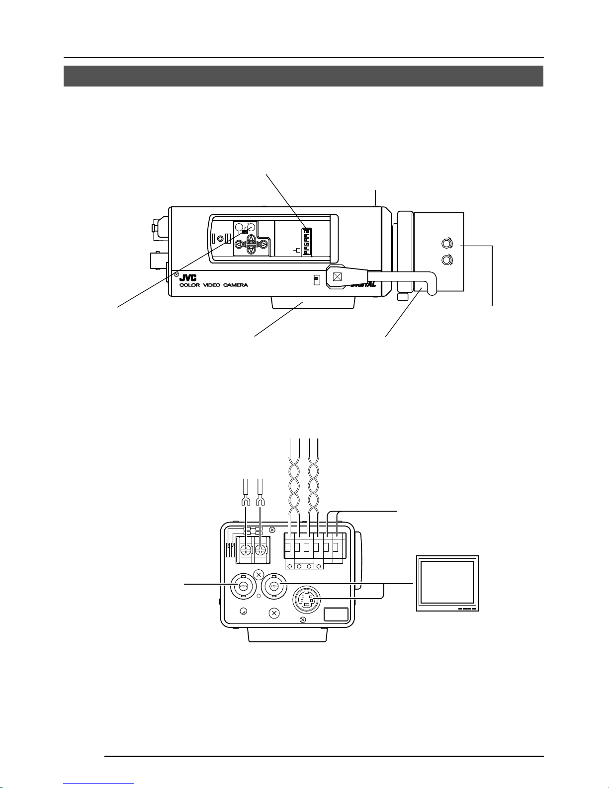
19
[DC 12V, AC 24V] Power input terminals
(TK-C1480BE)
To input DC 12V or AC 24V power.
20
[TX+A, TX-B, RX+C, RX-D] Control
signal connection terminals
Terminals for inputting signals with
electrical characteristics conforming to
the EIA/TIA RS-422A or RS-485 standard.
17
RX.TERM switch
21
[AUX, GND] Auxiliary Output Terminals
If any change occurs in the area that was
set on the MOTION DETECT screen, these
terminals output signals. ( Page 32)
[Open-collector Low signal. Maximum
voltage 30V, Current 30mA.]
22
[Y/C OUT] Y/C output connector
This 4-pin connector outputs the luminance
and chrominance signal.
• Pin configuration of Y/C OUT connector
23
[VIDEO OUT] Video signal output
connector
This BNC connector outputs a composite
video signal. Connect this to the video input
connector of a video monitor, switcher, etc.
24
[POWER] Power indicator lamp
This lamp lights when power is supplied
to the camera.
25
[SYNC IN] Sync signal input connector
This BNC connector accepts the input of
an external sync signal such as a composite
video (VBS) or black burst (BB) signal.
When a sync signal is input into this
connector, the camera operation is
automatically synchronized with the
external sync signal.
To terminate this connector at 75Ω, turn
ON the EXT.TERM switch
14
.
26
Power cable (TK-C1481BEG)
Connect to the commercial AC230V
outlet
Pin No. Signal
1 GND
2 GND
3 Luminance (Y)
4 Chrominance (C)
4
2
3
1
Y/C OUT
SYNC IN
POWER
VIDEO OUT
SEE INSTRUCTION
MANUAL
TX+TX
-
RX+RX
-
AUX
GND
A
B
CD
fl
TK-C1480BE TK-C1481BEG
Page 12

E-12
REC
PLAY
FFREW
REVERSE
PAUSE/
STILL
REC
CHECK
STOP/EJECT
COUNT/
CLOCK
TIME
MODE
TIMER
REC
AL/PL
RESET
MENU
VIDEO CASSETTE RECORDER
SHIFT/TRACKING
SET/V.LOCK
RESET
/CANCEL
OPERATE
SR-L910
OPE. LOCK
1
TO CAMERA
TO CAMERA
DATA I / O
DATA I / O
RX
RX
+
RX
RX
TX
TX
+
TX
TX
-
COM
COM
1 2 3 4 5 6 7 8
COM
COM
9/1
9/1
10/2
10/2
11/3
11/3
12/4
12/4
13/5
13/5
14/6
14/6
15/7
15/7
16/8
16/8
COM
COM
COM
COM
COM
COM
CAMERA
CAMERA
SW
SW
UNIT
UNIT
ALARM
ALARM
AUTO
AUTO
431 2 875 6
2 3 4 5 6 7
8
1
MONITOR
MONITOR
OUTPUT
OUTPUT
MONITOR
MONITOR
SERIAL-2
SERIAL-2
SERIAL-1
SERIAL-1
VIDEO INPUT
VIDEO INPUT
VIDEO OUTPUT
VIDEO OUTPUT
OUTPUT
OUTPUT
2
1
ON
ON
2 3 4 5 6 7
8
POWER
OFF
AC INPUT
ALC
LEVEL
Av Pk
L H
ALC
LEVEL
Av Pk
L H
ALC
LEVEL
Av Pk
L H
•••••
CAMERA
SW
Remote Control Unit
RM-P2580
Time lapse VCR
MONITOR
MONITOR
CAM SW
OUT
VIDEO IN
COM
TO
CAMERA
MONITOR
OUTPUT 2
MONITOR
OUTPUT 1
CONNECTION/INSTALLATION
RM-P2580 System
System with up to 8 cameras
Camera
TK-C1480B
Camera
TK-C1480B
Camera
TK-C1480B
Camera 1
Camera 2
Camera 8
Control signal cable
Video signal cable
Power
cable
AC24V
or
DC12V
AC24V
or
DC12V
AC24V
or
DC12V
MONITOR screen
(example showing camera ID as “05”)
This is the connected example of the TK-C1480BE.
When controlling with any system except the RM-P2580, execute proper settings using
switches and menu screens according to the systems used. ( Page 14)
PROT OOLDUPLEXID-05C :
“DUPLEX” should
be displayed.
The number shown in the
□□ part of ID-□□
should be correct.
MACHINE ID:1
(Menu screen)
RX TERM: OFF
(switch)
MACHINE ID:2
(Menu screen)
RX TERM: OFF
(switch)
MACHINE ID:8
(Menu screen)
RX TERM: ON
(switch)
MEMO
• When operating a system using the RM-P2580, several cameras (up to 8) can be connected and used on one control signal cable. Consequently, an incorrect switch setting on
just a single camera will cause the entire system to work incorrectly.
• Confirm switch settings on the screen as follows.
q Confirm that the image from the camera to be checked
is displayed on the monitor.
w Turn OFF and then ON the AC 24 V power to the cam-
era to be checked.
e The camera begins the initial operation and characters
similar to those shown in the illustration on the right
appear on the monitor screen.
r Confirm that “DUPLEX” and “ID-□□” are displayed and
that the ID number is the correct number (the number
should be the same as the number of the VIDEO INPUT terminal to which the camera is connected on the
rear panel of the RM-P2580).
t If wrong, set the camera ID again.
Page 13

E-13
CAMERA
SETUP
SET
MENU
EXT TERM-OFF
INT/GL
DUPLEX
RX TERM-OFF
NOT USED
ON
LL
SIMPLEX
ON
EXT TERM-OFF
INT/GL
DUPLEX
RX TERM-OFF
NOT USED
ON
LL
SIMPLEX
ON
VIDEO
DC
IRIS
AWC
A RX
+
B RX
C TX
+
D TX
TX+ A
TX
B
RX
+
C
RX D
TX
+
A
TX B
RX
+
C
RX
D
RM-P2580
Camera 2
control signal
connection terminals
Connect:
Camera TX+ to RM-P2580 RX+
Camera TX– to RM-P2580 RX–
Camera RX+ to RM-P2580 TX+
Camera RX– to RM-P2580 TX–
The A B C D marks indicated on both the
camera terminals and the RM-P2580 terminals facilitate correct connections. Connect
the terminals with identical marks.
Connecting the control signal cable
(Use a twisted-pair cable for connection. Page 17.)
Camera 1
control signal
connection terminals
Setting the switches ( Page 10)
Select the synchronization method of the
camera image.
Set the switch on all cameras to LL (Line Lock)
and match with the V. PHASE.
( Page 26.)
Set this switch to the DUPLEX
* If the setting is changed, be absolutely sure to
switch on the power again.
Set this switch to ON (signal termination ON)
only on the camera placed at the end of the
control signal cable.
Set to OFF on all other cameras.
Setting on the MENU screen ( Page 33)
* If the setting is changed, escape from the menu screen once, and definitely switch on the power again.
MACHINE ID setting switches
Set this item to match the RM-P2580 VIDEO
INPUT terminal number for each camera.
When connecting
● Turn OFF the power supply to all equipment to be used before making connections.
● Carefully read the Instructions for each piece of equipment to be used before making
connections.
● For the appropriate connection cables and the length of these, carefully read “Connections
on the back” on page 16.
● The control signal cable cannot be used for loop connection.
Set to M.DROP
Set to M.DROP when the RM-P2580 is used
as a remote control unit. When controlling
from another machine, make sure that it
matches the communication system used.
MMCO UNICAT ION
S T L E M. DROPY
MA H NE DII 1C
Page 14
E-14
CONNECTION/INSTALLATION
SET
MENU
CAMERA
SETUP
EXT TERM-OFF
INT/GL
DUPLEX
RX TERM-OFF
IOT USED
ON
LL
SIMPLEX
ON
VIDEO
DC
ALC
LEVEL
Av Pk
L H
DC12V
AC24V
CLASS 2 ONLY(U TYPE)
ISOLATED POWER ONLY
(E TYPE)
TX+TX
-
RX+RX
-
AUX
Y/C OUT
SYNC IN
POWER
VIDEO OUT
GND
ABCD
SEE INSTRUCTION
MANUAL
1
+
-
2
Execute connection/installation according to the procedures described below.
Turn OFF the power supply to all equipment to be used before making carefully.
1.
Mounting the lens
( Page 15)
4.
Setting the switches
( Page 13)
6.
Back focus adjustment
( Page 21)
5.
Lens adjustment
( Page 20)
7.
Auto white balance
control adjustment
( Page 22)
3.
Mounting the camera
( Page 18)
To controlling systems
such as RM-P2580
To alarm terminals
such as switches
Monitor
2.
Connections
( Page 16)
DC 12V/AC 24V
power supply
Genlock sync
signal generator
Procedures
This is the connected example of the TK-C1480BE.
TK-C1481BEG ( Page 16)
Page 15

E-15
Mounting the lens
VIDEO
DC
IRIS
VIDEO
DC
3
42
1
Mount the lens according to the procedures described below.
Attached 4 pin plugs
1.
Before mounting a lens, check whether
it is a C-mount or CS-mount lens.
To change the mounting method, loosen
the back-focus locking screw (M 2.6)
using a Phillips head screwdriver, turn
the back-focus adjusting ring with your
fingers or the screwdriver and change
the mounting method.
Dimension (b) of the lens shown in the
illustration must be as shown in the table
below. If (b) exceeds the value in the
table, it may damage the inside of the
camera or correct mounting may be impossible; never use such lenses. Do not
attach the C-mount lens when using a
CS-mount.
The F mark indicates a focal point.
2.
Mount the lens on the camera by turning
the lens clockwise. Adjust its position.
3.
When using an auto-iris lens with an EE
amplifier, turn the switch to the “VIDEO”
side. When no EE amplifier is equipped,
turn the switch to the “DC” side.
4.
If the lens has an auto-iris mechanism,
connect the lens cable after checking the
pin arrangement.
If the lens cable has a different type of
plug, use the 4-P plug supplied.
Lens Flange back (c) Dimension (b)
C mount lens 17.526mm 10mm or less
CS mount lens
12.5mm 5.5mm or less
1
3
4
2
B
F
L
O
C
K
1
3
2
4
(b)
(c)
F
Lens DC IRIS VIDEO IRIS
Pin No. (does not contain EE amplifier) (contain EE amplifier)
1 Brake
–
9V [max 50mA]
2 Brake
+
NC
3Drive
+
VIDEO
4Drive
–
GND
3.
2.
4.
Page 16

E-16
CONNECTION/INSTALLATION
Installing the ferrite core
To retain electromagnetic compatibility, use the ferrite cores provided when connecting to the
lens.
VIDEO
DC
IRIS
ALC
LEVEL
Av Pk
L H
Notes:
Install the ferrite cores within 50 mm of the camera-side connectors. (Fasten the ferrite
core with the wire clamp provided.)
Ferrite core
Video-iris lens
(or galvanometnc-iris lens)
DC12V
AC24V
CLASS 2 ONLY(U TYPE)
ISOLATED POWER ONLY
(E TYPE)
TX+TX
-
RX+RX
-
AUX
Y/C OUT
SYNC IN
POWER
VIDEO OUT
GND
A
B
CD
SEE INSTRUCTION
MANUAL
1
+
-
2
Connect the DC 12 V or the AC 24 V power
supply to the DC 12V/AC 24V terminals. To
prevent connection errors or a cable
disconnection, we recommend the use of lug
plates for the connections.
The following table shows the connection
distances and connection cables provided
that 2-conductor VVF cables (vinyl-insulated
vinyl sheath cables) are used.
Maximum extension
(reference)
Conductor
diameter
100 m 260 m 410 m 500 m
1.0∅mm 1.6∅mm 2.0∅mm 2.6∅mm
and more and more and more and more
Connections on the back
䡲 Power supply
TK-C1480BE (DC 12 V or AC 24 V)
Wire clamp
Page 17

E-17
Control signal cables
These cables should be connected only when
it is required to control the camera using the
RS-442A or RS-485 signals. The use of 0.65
4-conductor twisted pair cables is recommended. With these cables, the maximum extension distance is 1,200 m.
Connect to the other
side in pairs like this.
Connect to the other
side in pairs like this.
A
B
TX+
TX
-
C
D
RX+
RX
-
Genlock connection
With some systems, when the external sync
signal is a composite video or black burst signal genlocking by applying an external sync
input requires the horizontal phase (H
PHASE) and colour phase (SC COARSE) to
be adjusted.
MEMO
• Genlocking is not possible with a signal containing too much jitter, such as a VCR or
videodisc playback signal.
• For details, consult a JVC authorized dealer.
MEMO
• If thin cables are used (i.e. with a high resistance), a significant voltage drop will occur when
the unit is at its maximum power consumption. Either use a thick cable to restrict the voltage
drop at the camera side to below 10%, or place the power supply near to the camera. If
voltage drop occurs during operation, the performance will be unstable.
• Attach the cable conductors so that they do not come into contact with the drop prevention
wires.
• Do not allow input from both a DC 12 V and AC 24 V power supply at the same time.
• When using a DC 12 V power supply, ensure that the polarities of the cable are correct.
• The AC 24 V power supply should conform to the following:
TK-C1480BE Isolated power supply only
TK-C1481BEG (AC230V)
Power cable connect to the commercial
AC230V outlet
CAUTION:
When you use this camera, the socket-outlet shall be installed near equipment so
as to disconnect easily.
Y/C OUT
SYNC IN
POWER
VIDEO OUT
SEE INSTRUCTION
MANUAL
Page 18

E-18
DC12V
AC24V
CLASS 2 ONLY(U TYPE)
ISOLATED POWER ONLY
(E TYPE)
T
X
+
T
X
-
R
X
+
R
X
-
A
U
X
Y/C OUT
SYNC IN
POWER
VIDEO OUT
G
N
D
A
B
CD
S
E
E
IN
S
T
-
R
U
C
T
IO
N
M
A
N
U
A
L
+
-
1
2
2mm
6mm
M3 x 6mm
MAX.
7mm
Mounting the camera
CONNECTION/INSTALLATION
Camera mounting
screw
Camera-mounting bracket
Rotation prevention hole
When mounting the camera on a fixer, pan/
tilt, etc., use the camera mounting screw hole
located on the camera-mounting bracket.
Furthermore, make use of the rotation
prevention hole to prevent the camera from
falling and securely mount the camera.
Special precautions must be taken for
mounting the camera on a wall or a ceiling.
We are not liable for any damage caused by
improper installation.
Fall Prevention
• Exercise maximum caution when
installing the unit to the wall or ceiling. You
should not engage in the installation work
yourself. Ask a professional to do the job,
since the fall of the unit can result in
injuries and accidents.
• When installing the unit on a fixer, Pan/
Tilt unit, etc., make sure to install it firmly
using a rotation-preventing hole provided
to prevent fall.
• To prevent fall, connect the unit to a
section with sufficient strength (ceiling
slab or channel) using a fall prevention
wire such as a wire chain and the like.
Use the black screw on the back of the
unit for installation.
Pay utmost attention to the length of the
wire, too.
• Specified screw (M3 × 6 mm)
Never use any screw longer than the
specified length as the inside can be
damaged.
CAUTION:
Use the screw with a
length shorter than 7mm
from a camera-mounting
face.
This diagram shows the installed example of
the TK-C1480BE.
Be sure to install a fall preventive wire likewise in case of the TK-C1481BEG.
Page 19

E-19
VIDEO
DC
IRIS
VIDEO
DC
IRIS
Cameramounting bracket
Fixing screws
Installation of camera
• Mounting from the bottom
This camera is originally designed to be
mounted from the bottom, as shown q.
The hole is standard photographic panhead screw size (1/4-20 UNC). Example
the Fixing unit or Pan/Tilt unit.
• Mounting from the top
Remove the CAMERA MOUNTING
BRACKET from the bottom of the camera
by removing two fixing screws as shown
w. Attach the CAMERA MOUNTING
BRACKET to the top, then mount the
camera on the Fixing Unit as shown e.
Make sure that two original screws are
used when mounting the CAMERA
MOUNTING BRACKET. Be sure to use a
6 mm long locking screw for the cameramounting bracket.
(This camera is used indoor and under
similar conditions.)
q
w
e
Page 20

E-20
CONNECTION/INSTALLATION
Lens adjustment
ALC
LEVEL
Av Pk
L H
Connect the camera according to the connection method, turn it on, display an image on the
monitor, and check the image. The camera has been factory-adjusted to the best position, but
it may need to be adjusted according to the object conditions or combination of lenses. If the
image is unnatural, adjust it as follows: (Also read the instruction manual of the lens.)
• LEVEL adjustment
Monitor screen
LEVEL turning direction
Too bright Counterclockwise (Toward L)
Too dark Clockwise (Toward H)
MEMO
• If the sensitivity adjustment LEVEL is turned
excessively to L, the sensitivity increases
because of the AGC function of the camera, and the image looks grainy.
• If the video iris lens is set to too low a level,
malfunction such as the hunting phenomenon, in which the iris opens or closes unintentionally, may occur.
In such a case, first set LEVEL potentiometer on the lens to the H (iris open) position
then adjust it to the optimum level.
LEVEL
adjustment
ALC adjustment
(Does not operate.)
MEMO
Note that the lens cannot make ALC adjustments. Make ALC adjustments using the item
AVERAGE: PEAK on the menu.
( Page 26)
Page 21

E-21
Back focus adjustment
• With a fixed-focus lens
If the focus can not be adjusted correctly by
rotating the lens focus ring, adjust the back
focus as follows.
1.
Loosen the back focus locking screw by
turning it counterclocckwise (
) with a
screwdriver.
2.
Shoot a pattern closely.
3.
Turn the lens focus ring to ⬁.
4.
Turn the back focus adjustment ring to
focus at the best point.
5.
Tighten the back focus locking screw by
turning it clockwise (
).
• With a zoom lens
If the image is out of focus when zooming
(telephoto wide-angle), adjust the camera as
follows:
1.
Loosen the back focus locking screw by
turning it counterclocckwise (
) with a
screwdriver.
2.
Shoot a comparatively dark scene with
thin lines.
3.
Set the lens to the maximum telephoto
position, and adjust the lens focus.
4.
Set the lens to the maximum wide-angle
position, and turn the back focus ring to
adjust the focus.
(Repeat steps
3.
and 4. two or three
times.)
5.
Tighten the back focus locking screw by
turning it clockwise (
).
Back focus adjustment
Be sure to make back-focus adjustments when changing the lens mounting method or using
a different lens. If required, adjust it as follows:
MEMO
• LENS FOCUS ADJUSTMENT MODE
At the time of focus adjustment, press the
button
at the side of the unit for at least
one second to open the lens iris and to facilitate focusing. At this time, “LENS FOCUS
ADJUSTMENT MODE” will be displayed on
the monitor screen.
When the adjustment has been completed,
press one of the buttons
to can-
cel focus adjustment mode.
• When the subject is bright, the use of an
ND filter permits more accurate back-focus
adjustment. (The ND filter reduces the
amount of incident light upon the lens
equally over the entire range of wavelength.)
Back focus fixing
screw (M2.6)
Back focus
adjusting ring
Lens focus ring
B
F
L
O
C
K
Tighten
Loosen
Page 22

E-22
CONNECTION/INSTALLATION
Auto white balance control adjustment
Each light source has its own colour temperature. Therefore, when the main light source
lighting an object is changed, the white balance should be adjusted again by pressing the
AWC button.
1.
Place a white object under the same
lighting condition as the object to be shot
and zoom in to fill the screen with white.
2.
When the AWC button is pressed for
approx. one sec., the white balance is
adjusted for the object being recorded.
3.
During the time when the Auto White
function is operated, "AWC OPERATION" is displayed (for approx. 0.5 sec.).
When the appropriate white balance is
acquired, "AWC OK" is displayed.
4.
Error message display
● NG : OBJECT
Displayed when there is not enough
white colour on an object or the colour
temperature is not suitable.
By taking a shot of a white object to
fill the screen, adjust the white balance
again.
● ERROR : LOW LIGHT
Displayed when the light is low. Increase the illumination then re-adjust
the white balance.
● ERROR : HIGH LIGHT
Displayed when the light is too bright.
Decrease the illumination then re-adjust the white balance.
CAMERA
SETUP
SET
MENU
EXT TERM-OFF
INT/GL
DUPLEX
RX TERM-OFF
NOT USED
ON
LL
SIMPLEX
ON
VIDEO
DC
IRIS
AWC
AWC button
AWC OK
DISPLAYING RESULT
AWC OPERATION
DURING OPERATION
AWC NG : OBJECT
OBJECT ERROR
AWC ERROR : LOW LIGHT
LOW LIGHTING
AWC ERROR : HIGH LIGHT
OVER LIGHTING
Page 23

E-23
MENU SETTING
Setting the menu
CAMERA
SETUP
SET
MENU
EXT TERM-OFF
INT/GL
DUPLEX
RX TERM-OFF
NOT USED
CAMERA
SETUP
SET
MENU
ON
LL
SIMPLEX
ON
VIDEO
DC
IRIS
AWC
1.
Press the MENU button.
The MENU screen is displayed.
2.
Set the cursor (>) to a desired
sub-menu using the
,
button.
3.
Press the SET button.
The selected sub-menu screen is
displayed.
4.
Use the , button to set the
cursor (>) to a desired item.
5.
Change the set value using the
, button.
Change of the set value displays a
change mark (∗).
If you wish to change the set values of
another items, repeat items
2.
to
5.
above.
6.
Press the MENU button.
The screen returns to the previous one
(MENU screen).
7.
Press the MENU button.
The screen returns to the normal screen
(quitting the menu display).
* When the setting is executed using the RM-
P2580, use a joy stick instead of the
button.
LACSETTINGS
IIRSLEVEL NORMAL
AEVRAEG:PEAK 82:
ACGMODE
2dB0
SUTHTERExD
LUX
R/
NRMALO
L
O
OFF
PIORRITY –––
BCLOFF
SNSEEUP OFF
MODE
LACSETTINGS
AEVRAEG:PEAK 82:
ACGMODE
2dB0
SUTHTERExDR/
NRMALO
I∗IRS LEVEL -5
OFF
PIORRITY –––
BCLOFF
SNSEEUP OFF
LUX
L
O
MODE
MENU button
SET button
MENU
SYNC ADJUST
VIDEO ADJUST
MOD E ESLECT
ALC SETT I NGS
COMMUN I CAT ION
MA IN TEN NACE
MOT I ON
D
E
TECT
..
FACTORY SETTI NGS ..
..
..
..
..
..
..
LACSETTINGS
IIRSLEVEL NORMAL
AEVRAEG:PEAK 82:
ACGMODE
2dB0
SUTHTERExD
LUX
R/
NRMALO
L
O
OFF
PIORRITY –––
BCLOFF
SNSEEUP OFF
MODE
Page 24

E-24
MENU
SYNC ADJUST
VIDEO ADJUST
MOD E ESLECT
ALC SET T I NGS
COMMUN I CAT ION
MA I N TE N NACE
MOT I ON
D
E
TECT
SYNC DAJUST
VPHASE 0
HPHASE 0
SC ECOARS 0
SC F INE 1 28
DEVI O ADJUST
WH TE BA L E AT WNC
A
I
CO OUR LE NORMALEL
V
L
EN ANCE LE NORMALEL
V
H
PEESTAL LE NORMALEL
V
D
AUOBLAC K OFFTL
C
T
TIMO O N DE TECT
MO E OFFD
LE EL NORMALV
AR A EDIE
ALRMTI EM10sA
DEONSTRATIN
O
M
WH I T E BALANCE CONTROL
AWC SE T . .
RB
::
MG
::
g
INMA TE NANCE
CC SP OT. .D
DCC SPOT
CA ELNC
E
heat up 30min in advance
need Lens–cap to execute
XCTEUE
.
.
..
FACTORY SETTI NGS..
..
..
..
..
..
..
T..
MENU SETTING
The flow of menu screen
Page 26
Page 30
Page 32
Page 38
Page 35
Page 37
Page 38
Page 25

E-25
CTFA ORY SE NGSTT I
CA CELN
CL A W I(HOUT T I T LE )RTE
C
DATA CLEARED
LA()RALLE
LACSETTINGS
IIRSLEVEL NORMAL
AEVRAEG:PEAK 82:
ACGMODE
2dB0
SUTHTERExDDER/
NRMALO
LLUXOMO OFF
PIORRITY –––
BCLOFF
SNSEEUP OFF
MODE SE L EC T
CAMERA T I TL E ED I T. .
REV ERSE MODE OFF
HL I MODE OFF
ALM .T I TLE S ZEI DOUBLE
ALA RM COLOUR WH I TE
D.ZOOM MAX x 2
MMCO UNICAT ION
S T L E P TO PY
MA H NE DII – – –C
SHUT T RE/ExDR
SHUTTER SPEED
SPEED
1 120/
–––
–––
–––
FAST L IMIT
EDxER
EDxR
LLEV
M.
CAMERA T
ITL
E
’
ДЦ ВК ОФЫЗС
длп цьвко ф
Ü
ыбйну
аим тщзсЯ
¡¿
ú
0123456789
:-/
.,
ABCDE K LMNOPFGH I J
QRSTUVWXYZ
abcde klmnopf g hi j
qrstuvwxyz
TDislayitle
WIDE TELE
Page 26
Page 31
Page 33
Page 36
Page 34
Page 33
Page 27
Page 26

E-26
Item Functions and set values Initial value
V PHASE
H PHASE
SC COARSE
SC FINE
This adjusts the vertical synchronization to those of other cameras
when a selector switch for the synchronizing system on the side
is at LL. (50Hz power region only.)
When it is not set to LL, “---” will appear, disabling change
the set value.
[Set value: –156 to 0 to 156]
This adjusts the horizontal synchronization to those of other
cameras and systems when a selector switch for the
synchronizing system on the side is at INT/GL.
When external signals are not input, “---” will appear, disabling
change the set value.
[Set values: –16 to 0 to 16]
Coarse adjustment of the SC phase in gen-lock operation.
The SC phase can be varied by up to 90° in each direction.
Adjust with reference to another camera (or system) and
together with the SC FINE adjustment.
Adjust SC COARSE and SC FINE only after adjusting H
PHASE.
When it is not set to GL, “---” will appear, disabling change
the set value.
[Set values: 0°, 90°, 180°, 270°]
Fine adjustment of the SC phase in gen-lock operation.
When it is not set to GL, “---” will appear, disabling change
the set value.
[Set values: 0 to 255]
MENU SETTING
SYNC ADJUST Screen
This executes the setting regarding synchronization.
0
0
0°
128
ALC SETTINGS Screen
Item Functions and set values Initial value
IRIS LEVEL
AVERAGE:
PEAK
This makes automatic adjustments according to brightness.
Adjusts the brightness level of the video signal.
• To lower the brightness level ... Decrease the value
• To raise the brightness level .... Increase the value
[Set values: –5 to NORMAL to 5]
Sets the exposure detection as a ratio of the average value
and the peak value.
• AVERAGE value large: Increase the AVERAGE value
when portions other than the highlighted areas of the
screen are dark and look corrupted. (Ex. 10:0)
• PEAK value large: Increase the PEAK value when
halation occurs in the highlighted areas of the screen.
(Ex. 5:5)
[Set values: 10:0, 9:1, 8:2, 7:3, 6:4, 5:5]
NORMAL
8 : 2
Page 27

E-27
This sets the electronic shutter as well as the ExDR (Extended
Dynamic Range).
The use of an electronic shutter function enables shooting
with proper brightness, as more brightness results in higher
shutter speed.
The ExDR function allows even the shooting of a subject
having different luminous flux density by composing a picture
shot at 1/100 sec. shutter speed with a picture shot by a
high-speed shutter.
NORMAL: This fixes the shutter speed to 1/50.
The ExDR does not function.
MANUAL: This sets the shutter speed by the item
SHUTTER SPEED on the SHUTTER screen.
The ExDR does not function.
When SENSE UP is functioning, MANUAL
cannot be selected. (Not displayed on MENU)
AUTO: This automatically switches the shutter speed
according to brightness.
The ExDR does not function.
The item FAST LIMIT on the SHUTTER (ExDR)
screen sets a maximum shutter speed value.
M.ExDR: This is used when shooting a subject with
difference in a luminous flux density in the screen
under a fixed illumination condition, and so on.
During ExDR mode, the item M.ExDR.SPEED on
the SHUTTER (ExDR) screen sets the composing
high shutter speed. It is possible to set only when
the items BLC and SENSE UP are OFF. What’s
more, the ExDR LEVEL sets the signal level of
the composing high-speed shutter.
A.ExDR: This is used when the subjects having different
luminous flux densities are continuously used
night and day in the situation where both indoor
and outdoor subjects are mixed in existence, and
so forth. During ExDR mode, the composing
shutter speed automatically varies according to
the contrast of a subject. This is set when shooting
the subject with changing brightness.
This can be set only when the item BLC is OFF.
What’s more, the ExDR LEVEL sets the signal
level of the composing high-speed shutter.
MEMO
• Do not set to A.ExDR when using a manual lens.
• When M.ExDR mode or A.ExDr mode is used, the border
between a bright part and a dark part can be coloured
(cyan, orange, etc.), but this is not a malfunction.
This sets a shutter speed when MANUAL is set.
The AUTO, M. ExDR, A. ExDR set value is displayed as
“---” and cannot be changed
[Set values: 1/120, 1/250, 1/500, 1/1000, 1/2000, 1/4000,
and 1/10000]
NORMAL
1/120
Item Functions and set values Initial value
SHUTTER
/ExDR
* When the SHUTTER/ExDR item is set to NORMAL, the following items
(SHUTTER SPEED, FAST LIMIT, ExDR LEVEL, and M.ExDR SPEED)
cannot be changed.
SHUTTER
SPEED
Page 28

E-28
ALC SETTINGS Screen (Continued)
MENU SETTING
1/100000
NORMAL
1/4000
20dB
OFF
OFF
Item Functions and set values Initial value
FAST LIMIT
ExDR
LEVEL
M.ExDR
SPEED
AGC MODE
LOLUX MODE
SENSE UP
This sets the fastest value of a shutter speed when AUTO is set.
The MANUAL, M. ExDR, A. ExDR set value is displayed as “---”
and cannot be changed. The higher the shutter speed becomes,
the more smear phenomenon is emphasized, which is peculiar to
the CCD.
[Set values: 1/1000, 1/2000, 1/4000, 1/10000, 1/20000, 1/40000, 1/100000]
This sets the signal level of the composing high-speed shutter during
ExDR mode. This is set according to the brightness of a subject.
When using M.ExDR, be sure to set M.ExDR SPEED in advance.
When the SHUTTER/ExDR item is set to MANUAL or AUTO, “---”
appears, disabling setting.
To give priority to the low-brightness parts of the subject…
increase the value
To give priority to the high-brightness parts of the subject…
decrease the value
[Set values: –5 to NORMAL to 5]
MEMO
• In the case of a subject with a large difference in the luminous flux
density, sometimes images do not change even if ExDR LEVEL is
varied. However, this occurrence is a peculiarity of the unit and is
not a malfunction.
This sets the composing high shutter speed when ExDR is set to
M.ExDR. Set the shutter speed in order that a subject with a high
luminous flux density (outdoor, etc.) may come out most clearly. This
is displayed as “---” during MANUAL, AUTO or A. ExDR and cannot
be set.
[Set values: 1/500, 1/1000, 1/2000, 1/4000, 1/10000, 1/20000]
This sets a maximum gain of the AGC (Automatic Gain Control).
OFF: When the AGC function is not used.
10dB: When luminous energy is insufficient.
20dB: When luminous energy is extremely insufficient.
SUPER: When brightness is insufficient even when it is set to 20dB.
• If the gain is increased, the screen gets rough in a dark place.
• If it is set to SUPER, it can sometimes consume operation time to
cope with a drastic level change.
Used when brightness is low even when setting the AGC MODE.
(Functions regardless of the AGC MODE setting.)
OFF: LOLUX MODE is off
ON: LOLUX MODE is on (+6dB)
This item makes up a sensitivity should be heightened automatically
when a subject becomes dark.
In case of the X32 AUTO, the sensitivity is automatically heightened
up to 32 times continuously as compared with standard.
As the sensitivity becomes higher, the shutter speed becomes lower,
resulting in unnatural motion.
If SHUTTER/ExDR is set to MANUAL or the M.ExDR,
“---” will appear, disabling the SENSE UP function.
[Set values: OFF, X2 AUTO, X4 AUTO, X8 AUTO, X16 AUTO, X32
AUTO]
MEMO
• When the magnification of SENSE UP is enhanced, the screen
can become coarse or whitish, or whitish flaws can emerge
sometimes, but this is not abnormal.
Page 29

E-29
MOTION
OFF
OFF AREA 1 AREA 2 AREA 3 AREA 4
Light
metering
area
Light
metering
area
Light
metering
area
Light
metering
area
Light
metering
area
Item Functions and set values Initial value
PRIORITY
BLC
This item sets the order in which the AGC and slow shutter
speed decrease function when the object brightness
becomes low.
When the item AGC MODE or the item SENSE UP is set
to OFF, “---” will appear, disabling any setting.
MOTION: Priority is given to motion.
This is suitable to a subject with quick motion,
since the AGC (automatic gain control) functions
with priority when the subject becomes dark.
PICTURE: Priority is given to image.
When the subject becomes dark, SENSE UP
(sensitivity goes up) functions with priority,
offering suitability that gives priority to image.
Sets the backlight compensation function. Set when a
bright light source, etc. is placed in the same direction as
the subject.
If the item SHUTTER/ExDR is set to the M.ExDR or the
A.ExDR, “---” will appear, and the BLC does not function.
OFF: The backlight compensation function does not work.
AREA 1 to AREA 4: When the SET button is pressed, the
fixed light metering areas are displayed. Select one of
the four types. (Indicated positions on the screen are rough
guides. Execute required settings after checking and
confirming the functions on actual images.)
EDIT 1 to EDIT 2: When the SET button is pressed, the
user light metering areas are displayed. Select one of the
two types.
“BLC EDITTING Screen” on page 34.
Page 30

E-30
Item Functions and set values Initial value
WHITE
BALANCE
COLOUR
LEVEL
ENHANCE
LEVEL
PEDESTAL
LEVEL
AUTO
BLACK
CTL
Selects the white balance adjustment function. The white
balance can be adjusted manually or automatically for
light within the colour temperature range of 2500K to
8000K.
• ATW: Auto-Tracking White Balance mode.
This automatically adjusts the white balance.
• AWC: Auto White Balance Controll mode. When the
SET button is pressed, the adjustment
screen appears.
( Page 35)
To adjust the colour level of the video signal.
• To make colours lighter … Decrease the value
• To make colours darker … Increase the value
[Set values: –5 to NORMAL to 5]
To adjust the contour enhancing level of the video signal.
• To make the picture quality harder … Increase the value
• To make the picture quality softer … Decrease the value
[Set values: –5 to NORMAL to 5]
To adjust the pedestal level of the video signal.
• To brighten picture … Increase the value
• To darken picture … Decrease the value
[Set values: –5 to NORMAL to 5]
This is set when it is difficult to view a dark part of the
image even if gain is boosted by the AGC (automatic gain
control).
ON: When a black level of the image signal is low, a
pedestal level that becomes the standard of black
is automatically elevated, making it easier to view a
dark part.
OFF: AUTO BLACK does not function.
MEMO
• When PEDESTAL LEVEL is set to 5, no function can
take place even if AUTO BLACK CTL is ON.
• When AGC MODE is set to OFF, no function can take
place even if AUTO BLACK CTL is ON.
AT W
NORMAL
NORMAL
NORMAL
OFF
VIDEO ADJUST Screen
MENU SETTING
Adjustments are made on video signals.
Page 31

E-31
MODE SELECT Screen
Titles, image reversion, etc., are set.
Item Functions and set values Initial value
CAMERA
TITLE EDIT
REVERSE
MODE
HLI MODE
ALM.TITLE
SIZE
ALARM
COLOUR
D.ZOOM
MAX
–
OFF
OFF
DOUBLE
WHITE
x2
ALARM
ALARM
NORMAL DOUBLE
Bring up the CAMERA TITLE, EDIT screen.
( Page 36)
Settings are executed for image reversion.
OFF: Image does not reverse.
R-L: Left and right of the image are reversed.
U-D: Up and down of the image are reversed.
ALL: Up and down and left and right of the image are
reversed.
The highlighted part of the image is made black to make
the surroundings of the highlighted part better visible. Set
to HIGH when there are many highlighted parts.
[Set values: OFF, LOW, MIDDLE, HIGH]
Set the size of the characters displayed in the case of
alarms.
This sets the colour of an alarm title.
[Set values: WHITE, YELLOW, CYAN, GREEN]
This function sets the maximum zoom ratio of the
electronic zooming.
[Set values: x1, x2, x4, x6, x8, x10]
MEMO
• The electronic zoom function can only be used by the
communication command of exclusive controllers (RMP2580, etc.).
• Note Picture quality deteriorates under electronic
zooming as it is accompanied by digital image
processing.
• When the electronic zoom magnification ratio is
increased, there may be blurring in the upper center left
of the screen. This is a characteristic of the main unit
and is not a malfunction.
Page 32

E-32
Item Functions and set values Initial value
MODE
LEVEL
AREA EDIT
ALARM TIME
DEMONSTRATION
OFF
NORMAL
–
10s
–
MENU SETTING
MOTION DETECT Screen
This sets ON/OFF of motion detecting function.
OFF: Motion detecting function does not work.
ON: Motion detecting function works.
This sets the level that detects motion.
If the item MODE is set to OFF, “---” will appear, and
settings cannot be changed.
To function with large signal level change…decrease the
value
To function with small signal level change…increase the
value
[Set values: –5 to NORMAL to 5]
This sets the range in which the motion detecting function
works.
( Page 37)
This sets the output time of the alarm signal output of
AUX terminal as well as “ALARM” display on the screen
when motion is detected.
If the item MODE is set to OFF, “---” will appear, and
settings cannot be changed.
[Set values: OFF, 5s, 6s, 7s, 8s, 9s, 10s, 15s, 20s, 30s,
1min]
MEMO
When the MODE item is set to OFF, only the alarm signal
of the AUX terminal is output, and “ALARM” is not
displayed on the screen.
This is used when checking and confirming the set motion
detecting function. The detection area is shown in gray.
( Page 37)
Settings are executed about the motion detecting function that emits alarm signals when
there exists any motion in the image. Alarm signals are output from the auxiliary terminals on
the back.
Page 33

E-33
COMMUNICATION Screen
Item Functions and set values Initial value
STYLE
MACHINE ID
Settings are made for the control signal-connecting terminals on the back.
If the setting is changed, be absolutely sure to switch on the power again.
P TO P
– – –
White spot compensation is performed.
MAINTENANCE Screen
Item Functions and set values Initial value
CCD SPOT
The white spots on the screen, which are characteristic
for CCDs can be reduced.
Page 38 “White Spot Compensation”
–
Item Functions and set values Initial value
FACTORY
SETTINGS
Set values are returned to initial values.
The values set on the menu are returned to initial values.
CANCEL : No return to the initial value.
CLEAR : Returns set values except titles to the
(WITHOUT TITLE)
initial value.
CLEAR (ALL) : Returns all set values including titles
to the initial value.
Select respective set value and press the SET button.
Then, “DATA CLEARED” will appear for about 3 seconds.
Be sure not to switch off the power while the display is
still on.
MEMO
However, when making settings by means of transmitted
commands, the contents of the COMMUNICATION menu
do not return to the factory settings.
–
FACTORY SETTINGS Screen
This sets a communication system according to the
system used.
P TO P (Point to point)
This is set when a remote control unit controls a camera.
M.DROP (Multi-drop)
This is set when a remote control unit controls a plural
number of cameras.
This is set when the STYLE item is set to M.DROP. This
is the number that identifies individual cameras in a group.
No proper function can be realized if an ID number is
repeated within a system.
A combined use with the RM-P2580 necessitates the
setting together with the video input number of the RMP2580.
If the item STYLE is set to P TO P, “---” will appear, and
settings cannot be changed.
[Set values: 1 to 99]
Page 34

E-34
BLC EDITTING Screen
MENU SETTING
It is possible to set freely the light metering area for backlight compensation. The 2 screens
of EDIT1 and EDIT2 can be set.
CAMERA
SETUP
SET
MENU
AWC
LACSETTINGS
IIRS LEVEL NORMAL
AEV RAGE : PEAK 8 2:
SUTHTERExD
LUX
R/NRMALO
SPEURLO OFF
PIORRITY MTIONO
BCL
EDIT 1
SNSEEUP OFF
ACGMODE 2dB0
EDIT 1 screen
Light metering
area
Light metering
area
SET button
SET button
SET button
MENU button
EDIT 2 screen
1.
Set the item BLC on the ALC
SETTING screen to EDT1.
2.
Press the SET button.
The EDIT1 screen is brought up.
3.
Set the upper side and left side
of the metering area using the
button.
The sides having marks can
be changed.
4.
Press the SET button.
The changeable sides of the metering
area move to the right side and base
side.
5.
Set the base and right side of the
metering area using the
button.
If the SET button is pressed once more,
the two changeable sides of the metering area return to the top and left sides.
(The EDIT2 screen can also be set
likewise)
6.
Upon completion of setting,
press the MENU button.
The screen returns to ALC SETTING
SCREEN.
* To use the set metering area, set the item
BLC to EDIT1 or EDIT2.
Page 35

E-35
Manual Adjustment of White Balance
When automatic adjustment of the white balance results in a “reddish screen”, etc., adjust the
white balance manually.
1.
Set the WHITE BALANCE item on the
VIDEO ADJUST screen to AWC and
press the SET button.
* The WHITE BALANCE adjustment
screen appears on the monitor.
2.
Select the hue to be adjusted. (R/B or
Mg/G)
Press the
or button.
3.
Adjust the hue.
Press the
or button.
* The “ ı ” indicator moves in accordance
with the setting. When a setting is
changed, the “+” mark appears at the
original position.
4.
Concluding manual white balance adjustment.
Pushing the MENU button returns the
screen to VIDEO ADJUST.
DEVI O ADJUST
WH T E BA L E AWCNC
A
I
CO OUR L E NORMALEL
V
L
EN ANCE LE NORMALEL
V
H
PEESTAL LE NORMALEL
V
D
AUOBLACK OFFTL
C
T
WH I T E BALANCE CONTROL
AWC SE T. .
RB
::
MG
::
g
VIDEO ADJUST screen
WHITE BALANCE
CONTROL screen
CAMERA
SETUP
SET
MENU
AWC
SET buttonMENU button
Page 36

E-36
1.
Select the item CAMERA TITLE
on the MODE SELECT screen,
and push the SET button.
Then, the CAMERA TITLE screen is
brought up.
2.
Select the first character from the
character area using
buttons.
The selected character is displayed
flashing on and off.
3.
Push the SET button.
The first character gets fixed and the
blinking title input area moves to the
second character.
4.
Repeat the above items 2 to 3.
It is possible to use up to 24 characters
to input the title.
5.
Push the MENU button.
The screen returns to MODE SELECT.
Up to 24 characters can be selected as camera text for each camera. The set characters are
displayed at the bottom of the screen.
MENU SETTING
CAMERA TITLE Setting
CAMERA
SETUP
SET
MENU
AWC
SET buttonMENU button
MODE SEL E CT
CAMERA T I TLE ED I T . .
REV ERSE MODE OF F
ALM.T I TLE S ZEI DOUBLE
ALARM COLOUR WHI TE
MODE SELECT screen
CAMERA TITLE screen
CAMERA T
ITL
E
’
ДЦ ВК ОФЫЗС
длпцьвкоф
Ü
ыбйну
аимтщзсЯ
¡¿
ú
0123456789
:-/
.,
ABCDE KLMNOPFGHI J
QRSTUVWXYZ
abcde klmnopf g hi j
qrstuvwxyz
TDislayitle
WD
IE LETE
Space
Character area
Title input area
▲
Page 37

E-37
Setting the MOTION DETECT Function
It is possible to set freely the area where MOTION DETECTING functions.
TIMO ON DE T ECT
MO E OFFD
LE EL NORMALV
AR A EDI TE
ALRMTI EM10sA
DEONSTRAT I N
O
M
..
..
MOTION DETECT screen
flash
lights gray flash
Setting screen
1.
Select the item AREA EDIT on
the MOTION DETECT screen.
2.
Press the SET button.
The setting screen is brought up.
3.
Select the area not subject to
detection using the
button.
The area flashing ON and OFF in black
and white moves.
4.
Press the SET button.
The area not subject to detection is set,
and it turns gray (lights up).
To cancel the set area, press the SET
button again.
5.
Repeat items 3 and 4 above.
6.
Upon completion of setting,
press the MENU button.
The screen returns to the MOTION
DETECT menu.
MEMO
Indicated positions on the screen are rough
guides.
Be sure to check and conform the positions
on the actual screen.
* It is possible to check and confirm the set
areas on the DEMONSTRATION screen.
The detection area is shown in gray.
The motion detector is not a feature to prevent theft, fire, etc. Even if an accident should occur
resulting in damage, we do not accept any liability.
Page 38

E-38
White spot compensation
CCDs have the general characteristic that white spots appear on the screen when the CCD is
operated at high temperatures or when they are used with a slow shutter speed.
This unit has a built-in white spot compensation function to reduce these white spots.
(The number and the size of the white spots changes according to the use temperature, the
shutter speed, etc. Furthermore, there is a limit on the number of white spots that can be
compensated.)
Operation method
1.
Attach a lens cap or similar.
• Prevent entry of light to the CCD.
• Switch on the camera power supply
and wait for at least 30 minutes.
2.
Display the MAINTENANCE
screen.
• Confirm that the cursor (>) is at the item
CCD SPOT.
3.
Press the SET button.
• The CCD SPOT screen will be displayed.
• If you do not want to perform white spot
compensation, move the cursor (>) to
CANCEL and press the SET button.
4.
Move the cursor (>) to EXECUTE.
5.
Press the SET button.
• White spot compensation will operate.
(“SPOT SCAN OPERATION” is displayed during operation.)
6.
Confirm the display.
• When white spot compensation has
been performed correctly, “SPOT
SCAN OK” is displayed for about 5
seconds, and then return is made to
the CCD SPOT screen.
• When “SPOT SCAN ERROR: HIGH
LIGHT” is displayed, check that no light
enters into the CCD.
7.
Press the MENU button.
• Return to the MENU screen will be
made.
DCC SPOT
CA ELNC
EX C TEUE
heat up 30min in advance
need Lens–cap to execute
INMA T ENA NC E
CC SPOT ..D
SP T SCAN OKO
Page 39

E-39
OTHERS
Image pickup device: 1/2 type IT CCD, 752 (H) × 582 (V)
Synchronization method: Internal, Line lock, Full Genlock
Scanning frequency: (H) 15.625 kHz, (V) 50 Hz
Resolution: 480 TV lines (H)
VIDEO OUT: Composite video signal 1 V (p-p), 75 Ω (BNC)
Y/C OUT: Y: 1 V(p–p), 75 Ω
C: 0.3 V(p–p), 75 Ω
Video S/N ratio: 50 dB (AGC OFF)
Minimum required illumination: 0.6 lx (50 %, F1.2, AGC 20 dB)
0.3 lx (50 %, F1.2, AGC 20 dB, LOLUX MODE)
0.3 lx (25 %, F1.2, AGC 20 dB)
0.15 lx (25 %, F1.2, AGC 20 dB, LOLUX MODE)
0.019 lx (50 %, F1.2, AGC 20 dB, SENSE UP × 32)
0.01 lx (50 %, F1.2, AGC 20 dB, LOLUX MODE, SENSE UP × 32)
Communication: RS-422A or RS-485 (switchable)
9600 bit/s
Lens mount: C/CS mount
Power supply and power consumption: TK-C1480BE AC 24 V ` 50 Hz/60 Hz, DC 12 V —--- 500 mA
TK-C1481BEG AC220 V to AC240 V `, 50 Hz/60 Hz, 75 mA
Ambient temperature: –10 °C to 50 °C (operation)
0 °C to 40 °C (recommended)
Mass: TK-C1480BE 600 ˝
TK-C1481BEG 835 ˝
Accessory: Instructions ..................... 2 Ferrite core ...................... 1
4P plug ........................... 1
Design and specifications are subject to change without notice.
Specifications
SS412174H-002
TUV
Rheinland
Product Safety
..
geprufte
Sicherheit
..
-NE PAS OUVRIR.
RISQUE DE CHOC ELECTRIQUE
-DO NOT OPEN.
SHOCK HAZARD
SC46171H-001
WARNING:
AVIS:
1/4-20UNC
41
35
70
55
63
42
138
149
39
71
U1-32
54-R
DIMENSIONS (Unit: mm)
Page 40

VICTOR COMPANY OF JAPAN, LIMITED
TK-C1480B, TK-C1481B COLOUR VIDEO CAMERA
is a registered trademark owned by VICTOR COMPANY OF JAPAN, LTD.
is a registered trademark in Japan, the U.S.A., the U.K. and many other countries.
© 2002 VICTOR COMPANY OF JAPAN, LIMITED
Printed in Japan
LWT0064-001A
®
®
Page 41

G-1
Deutsch
BEDIENUNGSANLEITUNG
BF
LOOK
C
O
L
O
R
VIDEO
C
A
M
E
R
A
DIGITAL
∞
TK-C1480B
TK-C1481B
FARBVIDEOKAMERA
LWT0065-001A
(CD-ROM)
Page 42

G-2
WARNUNG:
SETZEN SIE DIESES GERÄT ZUR
VERRINGERUNG DES RISIKOS
VON FEUER UND ELEKTRISCHEM
SCHLAG NICHT REGEN ODER
FEUCHTIGKEIT AUS.
Wegen Entwurfsmodifikationen ist es möglich,
dass die in dieser Anleitung gegebenen Daten
ohne vorherige Ankündigung geändert werden.
Sicherheitsmaßnahmen
Page 43

G-3
Deutsch
Wir danken Ihnen für den Kauf unseres Erzeugnisses.
(Diese Anleitung gilt für das Modell TK-C1480BE und TK-C1481BEG)
Bitte lesen Sie diese Bedienungsanleitung vor der Verwendung des Gerätes
sorgfältig durch, damit Sie die bestmögliche Leistung erreichen können.
Inhalt
EINLEITUNG
Eigenschaften ......................................................................................................................4
Vorsichtshinweis für den Betrieb .........................................................................................5
Bedienungselemente, Anschlüsse und Anzeigen ...............................................................6
ANSCHLUSS/INSTALLATION
RM-P2580-System ............................................................................................................10
Verfahren ...........................................................................................................................12
Anbringen des Objektivs ................................................................................................... 13
Ferritkerninstallation ..........................................................................................................14
Anschlüsse auf der Rückseite ...........................................................................................14
Anbringen der Kamera ......................................................................................................16
Einstellen des Objektivs .................................................................................................... 18
Einstellen der Schnittweite ................................................................................................19
Einstellung für automatishen Weißabgleich ......................................................................20
MENÜEINSTELLUNG
Einstellen des Menüs ........................................................................................................ 21
Ablauf der Menübildschirme .............................................................................................. 22
Bildschirm SYNC ADJUST ................................................................................................24
Bildschirm ALC SETTINGS ............................................................................................... 24
Bildschirm VIDEO ADJUST ...............................................................................................28
Bildschirm MODE SELECT ...............................................................................................29
Bildschirm MOTION DETECT ...........................................................................................30
Bildschirm COMMUNICATION ..........................................................................................31
Bildschirm MAINTENANCE ...............................................................................................31
Bildschirm FACTORY SETTINGS .....................................................................................31
Bildschirm BLC EDITING .................................................................................................. 32
Manuelle Einstellung des Weissableichs ..........................................................................33
Einstellung CAMERA TITLE ..............................................................................................34
Einstellung der Bewegungsentdeckungsfunktion ............................................................. 35
Weißpunktausgleich .......................................................................................................... 36
SONSTIGES
Technische Daten .............................................................................................................. 37
Page 44

G-4
Eine neue DSP-Funktion bietet einen
erweiterten Dynamikbereich (ExDR) und
ermöglicht Aufnahme an hellen und an
dunklen Orten.
Die Verwendung eines neuen CCD-
Elements mit der Funktion SENSE UP
(X32) realisiert die minimale
Lichtflussdichte für ein Objekt von 0,6 lx
(F 1,2, 50%, AGC 20 dB) und 0,019 lx
(bei langsamem Verschluss).
Die Bewegungsentdeckungsfunktion
entdeckt Bewegung im Bild und gibt
Alarmsignale ab.
Die vorhandenen Y/C- und RS-422A/RS-
485-Anschlüsse bieten Kompatibilität mit
diversen Systemen.
Elektronischer Zoom
Der 10-fache elektronische Zoom
ermöglicht Überwachung in weit
größerem Detail.
Eigenschaften
Führen Sie vor Beginn einer wichtigen
Aufzeichnung unbedingt eine
Probeaufzeichnung durch, um
sicherzustellen, dass normale
Aufzeichnung möglich ist.
Wir akzeptieren keinerlei Haftung für
den Verlust einer Aufzeichnung, falls
eine Aufzeichnung wegen eines
Problems der Videokamera, des
Videorekorders oder des Videobandes
unmöglich sein sollte.
Wir akzeptieren keinerlei Haftung für
Beschädigung der Kamera, wenn
diese wegen unvollständiger Installation
auf Grund von Nichtbeachtung der
Installationsanweisungen heruntergefallen worden ist.
Die Bewegungsentdeckung ist keine
Eigenschaft zur Verh+Eung von
Diebstahl, Feuer usw. Auch im Falle
eines Schäden verursachenden
Unfalls lehnen wir jegliche
Verantwortung ab.
EINLEITUNG
In dieser Bedienungsanleitung verwendete Zeichen und Symbole.
ACHTUNG : Vorsichtshinweis zum Betrieb dieses Gerätes
MEMO : Bezug auf Einschränkung von Eigenschaften
: Bezugsseite oder Bezugspunkt
Page 45

G-5
Deutsch
● Schalten Sie zum Einsparen von Energie
die Stromversorgung des Systems aus,
wenn das System nicht verwendet wird.
● Diese Kamera ist für Verwendung in
Gebäuden entworfen worden. Achten Sie
bei Verwendung im Freien auf gute
Verwendung eines Gehäuses usw.
● Installieren und verwenden Sie die Kamera
nicht an den folgenden Orten.
• Orte, die Regen oder Feuchtigkeit
ausgesetzt sind.
• Orte mit Dämpfen oder Öldünsten, z.B.
in einer Küche.
• Orte mit einer Temperatur außerhalb des
Betriebstemperaturbereichs (–10°C bis
50°C).
• In der Nähe einer Strahlungsquelle, z.B.
Röntgenstrahlen, starke Radiowellen
oder Magnetismus.
• An Orten mit Vibrationen.
• An Orten mit viel Schmutz.
● Wenn diese Kamera und die daran
angeschlossenen Kabel an einem Ort
verwendet werden, an dem starke
elektromagnetische Wellen auftreten oder
Magnetismus vorhanden ist, z.B. in der
Nähe eines Radio- oder Fernsehsenders,
eines Leistungstransformators oder eines
Elektromotors, so kann es zu Bildstörungen
kommen und die Farben können
beeinträchtigt werden.
● Diese Kamera enthält einen AGC-Stromkreis.
Bei Verwendung unter schwachen
Lichtbedingungen wird deshalb die
Empfindlichkeit der Kamera automatisch
erhöht und das Bild kann ungleichförmig
erscheinen. Dies ist jedoch keine Fehlfunktion.
●
Wenn ein Transceiver, der starke
elektromagnetische Wellen verursacht, bei
aktivierter AGC-Funktion in geringer
Entfernung verwendet wird, so kann das Bild
durch Schwebung usw. beeinträchtigt werden.
Verwenden Sie deshalb die Kamera in
einer Entfernung von mindestens 3 m von
einem solchen transceiver.
● Wenn die Verstärkung bei Verwendung von
Leitungsverriegelung angehoben wird,
kann es manchmal auf dem Bildschirm zu
Schwebungen kommen, aber diese
Erscheinung wird durch Schwankungen
der Stromversorgungsfrequenz verursacht
und ist keine Fehlfunktion.
● Wenn diese Kamera im ATW-Modus
verwendet wird, können sich die
aufgezeichneten Farben wegen des
Betriebsprinzips des automatisch
nachlaufenden Weißabgleichs etwas von
den tatsächlichen Farben unterscheiden.
Dies ist jedoch keine Fehlfunktion.
●
Wenn ein sehr helles Objekt (z.B. eine Lampe)
aufgenommen wird, kann das Bild auf dem
Bildschirm vertikale Linien (Schmieren) oder
Unschärfe (Fahnenziehen) an der Peripherie
haben. Dies ist eine Charakteristik des CCDElements und kein Defekt.
● Beachten Sie beim Warten der Kamera die
folgenden Punkte.
• Schalten Sie vor Beginn der Wartung die
Stromversorgung aus.
Wenn die Kamera stark verschmutzt ist, so
reinigen Sie die verschmutzten Teile mit einem
Lappen oder einem Papiertaschentuch,
angefeuchtet mit einer Lösung von Wasser
und einem neutralen Waschmittel.
●
Das Gerät wird durch eine Stromversorgung
mit 12 V Gleichspannung oder 24 V
Wechselspannung angetrieben.
(TKC1480BE)
Die Stromversorgung mit 24 V
Wechselspannung sollte den folgenden
Punkten entsprechen: Nur isolierte
Stromversorgung
TK-C1481BEG: Schließen Sie das Netzkabel an
eine kommerzielle Stromversorgung von 230 V an.
● Hinweis für den Betrieb von Objektiven mit
Videoblende
Wenn ein Objektiv mit Videoblende zu niedrig
eingestellt wird, kann es zu Fehlfunktion mit
Aufpendeln kommen, wobei die Blende sich
ungewollt öffnet und schließt.
Stellen Sie in einem solchen Fall das
Potenziometer “LEVEL” am Objektiv auf H
(offene Blende), und stellen Sie dann den
optimalen Pegel ein.
● Der Kabelstopper am Klemmenblock kann
sich manchmal lösen. Nehmen Sie sich
deshalb ausreichend Zeit, um das Kabel
sicher zu befestigen.
● Wenn ein extrem helles Objekt
aufgenommen wird, kann es manchmal zu
wellenförmiger Bewegung der vertikalen
Linien des Objektes kommen. Diese
Erscheinung ist jedoch eigentümlich für
das Gerät und nicht ein Anzeichen für eine
Fehlfunktion.
Vorsichtshinweis für den Betrieb
Page 46
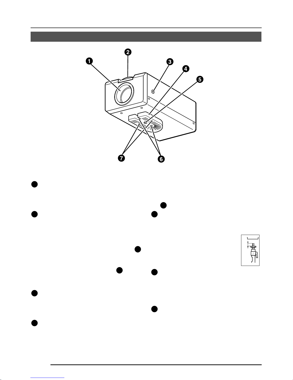
G-6
EINLEITUNG
Bedienungselemente, Anschlüsse und Anzeigen
1
Objektivfassung
Die Objektivfassung ist mit kompatibel
mit Objektiven mit C-Fassung und mit
CS-Fassung.
2
Einstellring für die Schnittweite
Dieser Ring ermöglicht Einstellung der
Schnittweite und Umschalten der
Objektivanbringung zwischen C- und CSFassung.
Lösen Sie die Schraube BF LOCK
3
durch Drehen gegen den Uhrzeigersinn,
bevor Sie diesen Ring drehen, und
sichern Sie die Schraube
3
durch
Drehen im Uhrzeigersinn, nachdem Sie
diesen Ring gedreht haben.
3
[BF LOCK] Feststellschraube für die
Schnittweite
Diese Schraube verriegelt den
Einstellmechanismus für die Schnittweite.
4
Kamerahalterung
Die Halterung ist vor dem Versand an der
Unterseite der Kamera angebracht
worden. Sie kann entsprechend den
Umständen auch an der Oberseite
angebracht werden.
Verwenden Sie zur Neuanbringung der
Halterung die Gewindelöcher an der
Oberseite mit den Befestigungsschrauben
7
für die Kamerahalterung. .
5
Stativgewinde (1/4 Zoll) für Kamerabefestigung
Verwenden Sie dieses Gewinde zum
Anbringen der Kamera auf eine einer
Befestigungseinheit, einem
Kameraschwenkkopf usw.
(Verwenden Sie eine Schraube
mit einer Gewindelänge von
weniger als 7 mm.)
6
Drehverhütungsloch
Verwenden Sie dieses Drehverhütungsloch,
um ein Herabfallen der angebrachten
Kamera zu verhüten. Stellen Sie sicher,
dass die Kamera sicher angebracht ist.
7
Feststellschrauben für die
Kamerahalterung (M2,6 × 6 mm, 2 Stück)
Achten Sie darauf, eine 6 mm lange
Schraube zu verwenden.
MAX.
7
mm
Page 47
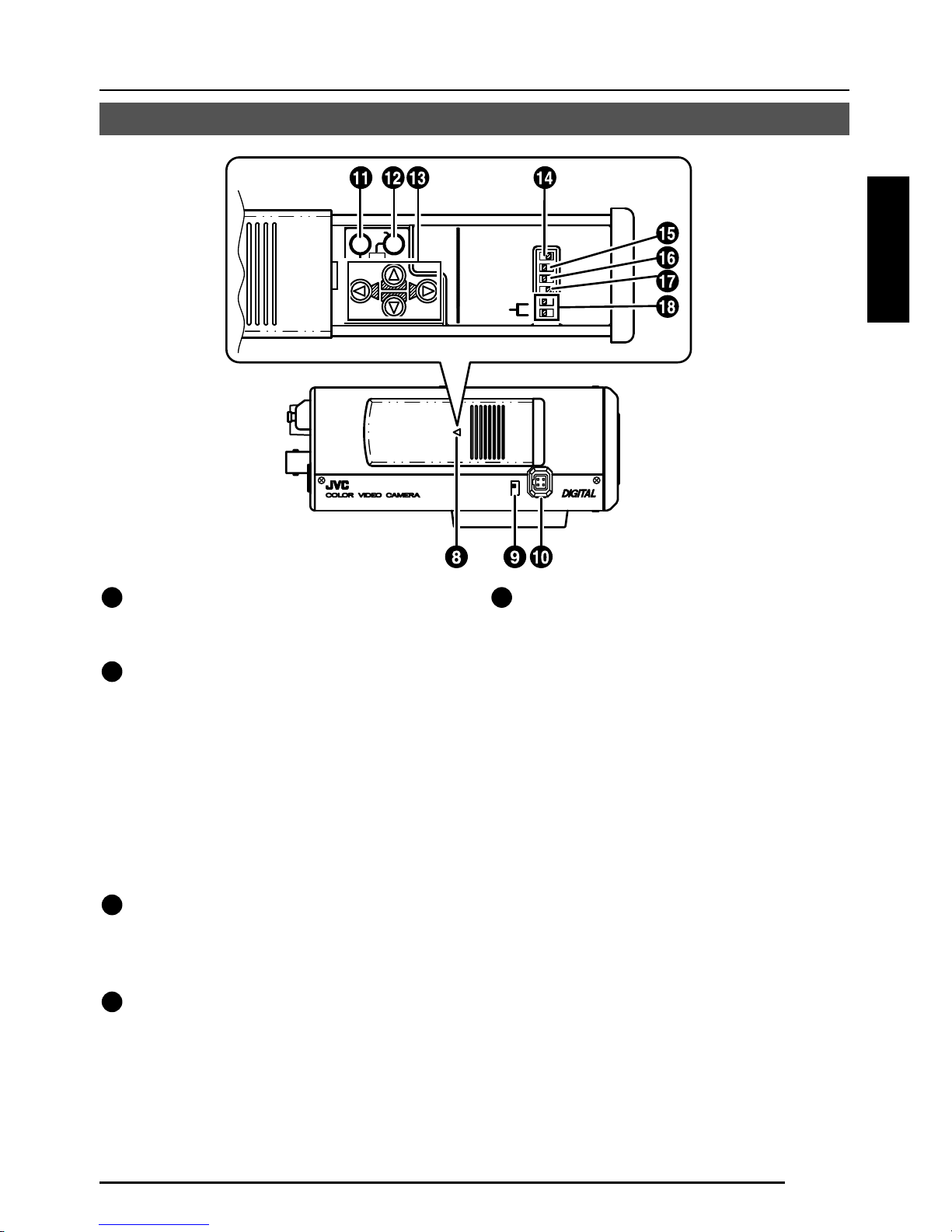
G-7
Deutsch
ON
SIMPLEX
ON
LL
SET
AWC
MENU
CAMERA
SETUP
EXT TERM-OFF
INT/GL
DUPLEX
RX TERM-OFF
NOT USED
VIDEO
DC
IRIS
8
Deckel
Der Deckel öffnet sich, wenn er gedrückt
und nach links geschoben wird.
9
[VIDEO/DC] Blendenwahlschalter
Bei Verwendung eines Objektivs mit
automatischer Blendensteuerung wird
dieser Schalter entsprechend dem
Objektivtyp eingestellt.
VIDEO: Für ein Objektiv mit eingebautem
EE-Verstärker.
DC: Für ein Objektiv ohne eingebauten
EE-Verstärker
(VIDEO: Werkseinstellung)
10
[IRIS] Blendenanschluss
Hier wird ein Objektiv mit automatischer
Blendensteuerung angeschlossen.
( Seite 13)
11
[MENU] Menütaste
Wenn diese Taste gedrückt wird,
erscheint ein Menübildschirm.
( Seite 21)
12
[SET/AWC] Taste für Untermenüs und
für Einstellen von automatischem
Weißabgleich
SET: Drücken Sie diese Taste zur
Anzeige eines Untermenüs.
( Seite 21)
AWC: Wenn diese Taste länger als eine
Sekunde gedrückt wird, so wird
die Funktion für automatischen
Weißabgleich durch einen
Tastendruck aktiv und führt
Weißabgleich durch. Sobald die
Einstellung durchgeführt worden
ist, ändert sich der Weißabgleich
nicht mehr, auch wenn sich die
Farbtemperatur ändern sollte. Es
ist auch möglich, Feineinstellungen
für den eingestellten Weißabgleich
durchzuführen.
( Seite 20)
Page 48

G-8
Bedienungselemente, Anschlüsse und Anzeigen (fortgesetzt)
EINLEITUNG
13
[ , , , ] Tasten für aufwärts,
abwärts, rechts und links
Hiermit können Menüpunkte gewählt und
Einstellwerte verändert werden.
( Seite 21)
14
[EXT.TERM-ON/OFF] Ein-/Ausschalter
für den Abschlusswiderstand für das
externe Synchronisationssignal
Hiermit kann der Abschlusswiderstand von
75 Ω fur den Synchronisationssignaleingang
zum Anschluss
25
SYNC IN an der Rückseite
des Gerätes ein- oder ausgeschaltet werden.
ON: Der Abschlusswiderstand von 75Ω
ist eingeschaltet.
OFF: Der Abschlusswiderstand von 75Ω
ist nicht eingeschaltet.
(ON: Werkseinstellung)
15
[INT/GL, LL] Wahlschalter für das
Synchronisationssystem
Hiermit kann das Synchronisationssystem
für die Kamera eingestellt werden.
INT/GL:
Hiermit wird interne (INT) oder externe
(GL) Synchronisation eingestellt.
LL (Leitungsverriegelung):
Die vertikale Synchronisation der
Kamera wird der Frequenz der 24V
Wechselspannung Stromversorgungsleitung angepasst.
Bei Umschalten zwischen mehreren
Kameras mit einem Umschalter kann
Wahl dieses Modus und Einstellen der
vertikalen Phase die Störungen der
Monitorsynchronisation beim Umschalten
des Kamerabildes verringern. (Diese
Funktion kann nicht in Bereichen verwendet
werden, in denen die Netzfrequenz 60 Hz)
(INT/GL: Werkseinstellung)
16
[DUPLEX, SIMPLEX] Wahlschalter für
das Übertragungssystem
Wenn die Einstellung geändert worden
ist, so schalten Sie unbedingt die
Stromversorgung aus und wieder ein.
DUPLEX:
Dies ist die Einstellung für Übertragungen
zwischen der Kamera und einer entfernten
Steuerung nach dem Duplexsystem
(Zweiweg-System).
SIMPLEX:
Dies ist die Einstellung für Übertragungen
zwischen der Kamera und einer entfernten
Steuerung nach dem Simplexsystem
(Einweg-System).
(DUPLEX: Werkseinstellung)
17
[RX.TERM-ON/OFF] Ein-/Ausschalter
für den Abschlusswiderstand für das
RX-Signal
Hiermit wird eingestellt, ob ein
Abschlusswiderstand von 110 Ω zwischen
20
RX+ und Rx– an der Ruckseite
angeschlossen werden soll oder nicht.
ON:
Abschlusswiderstand eingeschaltet
OFF:
Abschlusswiderstand nicht eingeschaltet
Wenn das System einschließlich der
Kamera des M.DROP-System (Multidrop, RS-485) ist, so wird nur die am
Anschluss für das Steuersignalkabel
angeschlossene Kamera auf “ON”
gestellt, und alle anderen Kameras
werden auf OFF gestellt. Im Fall des
M.DROP-Systems ist es erforderlich, die
ID-Nummer für die Maschine einzustellen.
( Seite 31)
Wenn das System einschließlich der
Kamera des P-TO-P-System (Punkt-zuPunkt-System RS-422A) ist, so stellen
Sie alle Kameras auf “ON”.
M.DROP bzw. P TO P wird mit dem Punkt
STYLE des Bildschirms COMMUNICATION eingestellt. ( Seite 31)
(ON: Werkseinstellung)
18
NOT USED (Nicht verwendet)
Nicht verwendbar. Nicht umschalten.
Page 49
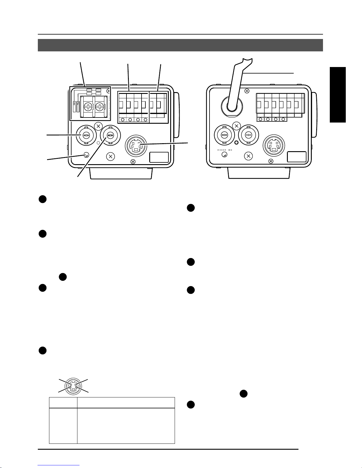
G-9
Deutsch
DC12V
AC24V
Y/C OUT
SYNC IN
POWER
VIDEO OUT
SEE INSTRUCTION
MANUAL
+
-
12
CLASS 2 ONLY(U TYPE)
ISOLATED POWER ONLY
(E TYPE)
TX+TX
-
RX+RX
-
AUX
GND
A
B
CD
⁄
)
(
fi
›
¤
‹
19
[DC 12 V, AC 24 V] Stromversorgungsanschlüsse
(TK-C1480BE)
Für Versorgung mit 12 V Gleichspannung
oder 24 V Wechselspannung.
20
[TX+A, TX-B, RX+C, RX-D] Steuersignalanschlüsse
Anschlüsse für Eingabe von Signalen mit
elektrischen Charakteristiken entsprechend
dem Standard EIA/TIA RS-422A oder RS-
485.
17 Schalter RX.TERM.
21
[AUX, GND] Hilfsausgangsanschlüsse
Wenn eine Änderung in dem am Bildschirm
MOTION DETECTING eingestellten Bereich
eintritt, werden von diesen Anschlüssen
Signale ausgegeben. ( Seite 30)
[Offener Kollektor, L-Signal. Maximale
Spannung: 30 V, Strom: 30 mA.]
22
[Y/C OUT] Y/C-Ausgangsanschluss
An diesem vierstiftigen Anschluss wird das
Luminanz- und Chrominanzsignal ausgegeben.
• Stiftbelegung des Anschlusses Y/C OUT
23
[VIDEO OUT] Videosignalausgangsanschluss
An diesem BNC-Anschluss wird ein
Komponentenvideosignal ausgegeben.
Schließen Sie dieses Signal an den
Videoeingangsanschluss eines
Videomonitors, Umschalters usw. an.
24
[POWER] Stromversorgungsanzeige
Diese Anzeige leuchtet, wenn die Kamera
mit Strom versorgt wird.
25
[SYNC IN] Eingangsanschluss für das
Synchronisationssignal
An diesem BNC-Anschluss kann ein
externes Synchronisationssignal wie das
Komponentenvideosignal (VBS) oder das
Schwarzsynchronsignal (BB) angelegt
werden. Wenn ein Synchronsignal an diesen
Anschluss angelegt wird, so wird der
Kamerabetrieb automatisch mit dem externen
Synchronisationssignal synchronisiert.
Für Anlegen eines Abschlusswiderstands
von 75 Ω an diesen Anschluss, stellen Sie
den Schalter
14
EXT.TERM auf ON.
26
Netzkabel (TK-C1481BEG)
An eine Netzsteckdose mit 230 V
Wechselspannung anschließen.
Stift Nr. Signal
1 GND
2 GND
3 Luminanz (Y)
4 Chrominanz (C)
4
2
3
1
Y/C OUT
SYNC IN
POWER
VIDEO OUT
SEE INSTRUCTION
MANUAL
TX+TX
-
RX+RX
-
AUX
GND
A
B
CD
fl
TK-C1480BE
TK-C1481BEG
Page 50

G-10
REC
PLAY
FFREW
REVERSE
PAUSE/
STILL
REC
CHECK
STOP/EJECT
COUNT/
CLOCK
TIME
MODE
TIMER
REC
AL/PL
RESET
MENU
VIDEO CASSETTE RECORDER
SHIFT/TRACKING
SET/V.LOCK
RESET
/CANCEL
OPERATE
SR-L910
OPE. LOCK
1
TO CAMERA
TO CAMERA
DATA I / O
DATA I / O
RX
RX
+
RX
RX
TX
TX
+
TX
TX
-
COM
COM
1 2 3 4 5 6 7 8
COM
COM
9/1
9/1
10/2
10/2
11/3
11/3
12/4
12/4
13/5
13/5
14/6
14/6
15/7
15/7
16/8
16/8
COM
COM
COM
COM
COM
COM
CAMERA
CAMERA
SW
SW
UNIT
UNIT
ALARM
ALARM
AUTO
AUTO
431 2 875 6
2 3 4 5 6 7
8
1
MONITOR
MONITOR
OUTPUT
MONITOR
MONITOR
SERIAL-2
SERIAL-2
SERIAL-1
SERIAL-1
VIDEO INPUT
VIDEO INPUT
VIDEO OUTPUT
OUTPUT
2
1
ON
2 3 4 5 6 7
8
POWER
OFF
ON
AC INPUT
ALC
LEVEL
Av Pk
L H
ALC
LEVEL
Av Pk
L H
ALC
LEVEL
Av Pk
L H
•••••
CAMERA (Kamera)
Fernsteuerung
RM-P2580
Zeitraffer-Videorekorder
MONITOR
(Monitor)
CAM SW OUT
(Kameraschalter,
Ausgang)
VIDEO IN
COM (Kommunikation)
TO CAMERA
(Zur Kamera)
MONITOR OUTPUT 2
(Monitorausgang 2)
MONITOR OUTPUT 1
(Monitorausgang 1)
ANSCHLUSS/INSTALLATION
RM-P2580-System
System mit bis zu acht Kameras
Kamera
TK-C1480B
Kamera 1
Kamera 2
Kamera 8
Steuersignalkabel
Videosignalkabel
Netzkabel
Dies ist ein Anschlussbeispiel für TK-C1480BE.
Wenn ein anderes System als RM-P2580 gesteuert wird, so führen Sie die angemessenen Einstellungen
mit den Schaltern und den Menübildschirmen entsprechend dem verwendeten System ein. ( Seite 12)
PROT OOLDUPLEXID-05C :
MACHINE ID: 1
(Menübildschirm)
RX TERM: OFF
(Schalter)
MACHINE ID: 2
(Menübildschirm)
RX TERM: OFF
(Schalter)
MACHINE ID: 3
(Menübildschirm)
RX TERM: ON
(Schalter)
12 V Gleichspannung
oder
24 V Wechselspannung
SW (Schalter)
MONITOR
(Monitor)
Monitorbildschirm
(Beispiel für die Kamera-ID “05”)
“DUPLEX” sollte
angezeigt werden.
Die im Abschnitt □□ von
ID-□□ gezeigte Nummer
sollte korrekt sein.
12 V Gleichspannung
oder
24 V Wechselspannung
12 V Gleichspannung
oder
24 V Wechselspannung
MEMO
•
Wenn ein System mit RM-P2580 betrieben wird, so können mehrere Kameras (bis zu acht) an ein Steuersignal
angeschlossen und verwendet werden. Dementsprechend verursacht eine flasche Schaltereinstellung an
auch nur einer Kamera, dass das gesamte System nicht richtig funktioniert.
•
Bestätigen Sie die Schaltereinstellungen am Bildschirm wie folgt.
q
Bestätigen Sie, dass das Bild von der zu überprüfenden
Kamera auf dem Bildschirm angezeigt wird.
w
Schalten Sie die 24-V-Wechselstromversorgung zu der zu
überprüfenden Kamera aus (OFF) und wieder ein (ON).
e Die Kamera beginnt mit dem anfänglichen Betrieb, und
Zeichen ähnlich der Abbildung auf der rechten Seite
erscheinen auf dem Monitorbildschirm.
r Bestätigen Sie, dass “DUPLEX” und “ID-□□ ”
angezeigt werden und dass die ID-Nummer die
korrekte Nummer ist (die Nummer sollte die gleiche
Nummer wie die des Anschlusses VIDEO INPUT sein,
an den die Kamera an der Rückseite des Modells RM-
P2580 angeschlossen ist).
t
Wenn dies nicht der Fall ist, so stellen Sie die Kamera-ID neu ein.
Kamera
TK-C1480B
Kamera
TK-C1480B
Page 51

G-11
Deutsch
CAMERA
SETUP
SET
MENU
EXT TERM-OFF
INT/GL
DUPLEX
RX TERM-OFF
NOT USED
ON
LL
SIMPLEX
ON
EXT TERM-OFF
INT/GL
DUPLEX
RX TERM-OFF
NOT USED
ON
LL
SIMPLEX
ON
VIDEO
DC
IRIS
AWC
A RX
+
B RX
C TX
+
D TX
TX+ A
TX
B
RX
+
C
RX D
TX
+
A
TX B
RX
+
C
RX
D
RM-P2580
Kamera 2
Steuersignalanschlüsse
Wie folgt anschließen:
TX+ der Kamera an RX+ von RM-P2580
TX– der Kamera an RX– von RM-P2580
RX+ der Kamera an TX+ von RM-P2580
RX– der Kamera an TX– von RM-P2580
Markierungen A, B, C und D an den
Anschlüssen an der Kamera und an RMP2580 erleichtern korrekten Anschluss.
Verbinden Sie Anschlüsse mit der gleichen
Markierung.
Anschluss des Steuersignalkabels
(Verwenden Sie für den Anschluss ein verdrilltes Kabel. Seite 15)
Kamera 1
Steuersignalanschlüsse
Einstellen der Schalter ( Seite 8)
Wählen Sie die Synchronisationsmethode für das
Kamerabild.
Stellen Sie den Schalter an allen Kameras auf LL
(Leitungsverriegelung) und passen Sie mit V. PHASE an.
( Seite 24)
Stellen Sie auf DUPLEX.
*
Wenn die Einstellung geändert worden ist, so schalten
Sie unbedingt die Stromversorgung aus und wieder ein.
Stellen Sie diesen Schalter nur für die Kamera am Ende
des Steuersignalkabels auf ON (Einschalten des
Signalabschlusswiderstands).
Stellen Sie diesen Schalter für alle anderen Kameras
auf OFF.
Einstellungen am Bildschirm MENU ( Seite 31)
* Wenn die Einstellung geändert worden ist, so verlassen Sie das Men_ einmal und schalten Sie
die Stromversorgung aus und wieder ein.
MACHINE ID: Schalter für Einstellung der
Maschinen-ID
Stellen Sie für jede Kamera entsprechend der
Anschlussnummer VIDEO INPUT von RM-P2580 ein.
Beim Anschluss zu beachten
●
Schalten Sie vor der Herstellung von Anschlüssen die Stromversorgung für alle Geräte aus.
● Lesen Sie die Bedienungsanleitung für jedes zu verwendende Gerät sorgfältig durch, bevor
Sie Anschlüsse herstellen.
● Lesen Sie für die angemessenen Anschlusskabel und ihre Längen sorgfältig “Anschlüsse auf
der Rückseite” auf Seite 14.
● Das Steuersignalkabel kann nicht für einen Schleifenanschluss verwendet werden.
Stellen Sie auf M.DROP.
Stellen Sie auf M.DROP, wenn RM-P2580 als
Fernsteuerung verwendet wird. Stellen Sie bei
Steuerung von einer anderen Maschine her sicher,
dass die Einstellung dem verwendeten
Kommunikationssystem entspricht.
MMCO UNICAT ION
S T L E M. DROPY
MA H NE DII 1C
Page 52

G-12
ANSCHLUSS/INSTALLATION
SET
MENU
CAMERA
SETUP
EXT TERM-OFF
INT/GL
DUPLEX
RX TERM-OFF
IOT USED
ON
LL
SIMPLEX
ON
VIDEO
DC
ALC
LEVEL
Av Pk
L H
DC12V
AC24V
CLASS 2 ONLY(U TYPE)
ISOLATED POWER ONLY
(E TYPE)
TX+TX
-
RX+RX
-
AUX
Y/C OUT
SYNC IN
POWER
VIDEO OUT
GND
ABCD
SEE INSTRUCTION
MANUAL
1
+
-
2
Führen Sie Anschluss/Installation entsprechend den nachfolgend beschriebenen Verfahren
durch.
Schalten Sie vor der Herstellung die Stromversorgung für alle zu verwendenden Geräte aus.
1.
Anbringen des Objektivs
( Seite 13)
4.
Einstellen der Schalter
( Seite 11)
6.
Schnittweiteneinstellung
( Seite 19)
5.
Objektiveinstellung
( Seite 18)
7.
Einstellung für automatischen
Weißabgleich
( Seite 20)
3.
Anbringen der Kamera
( Seite 16)
Zum Steuersystem,
z.B. RM-P2580
Zu Alarmklemmen,
z.B. Schaltern
Monitor
2.
Anschlüsse
( Seite 14)
Stromversorgung
12 V Gleichspannung/
24 V Wechselspannung
Verfahren
Genlock-
Synchronisation
ssignalgenerator
Dies ist ein Anschlussbeispiel für TK-C1480BE.
TK-C1481BEG ( Seite 14)
Page 53

G-13
Deutsch
Anbringen des Objektivs
VIDEO
DC
IRIS
VIDEO
DC
3
42
1
Bringen Sie das Objektiv entsprechend der nachfolgend beschriebenen Verfahren an.
Angebrachte 4 Anschlussfahnen
1.
Überprüfen Sie vor dem Anschluss eines
Objektivs, ob es eine C- oder eine CSFassung hat.
Wenn Sie die Anbringungsmethode ändern
wollen, so lösen Sie die Feststellschraube
(M 2,6) für die Schnittweite mit einem
Kreuzschlitzschraubenzieher, drehen Sie
den Einstellring für die Schnittweite mit den
Fingern oder mit einem Schraubenzieher,
und ändern Sie die Anbringungsmethode.
Die in der Abbildung gezeigte Abmessung
(b) muss wie in der folgenden Tabelle
gezeigt sein. Wenn (b) den in der Tabelle
gezeigten Wert überschreitet, kann das
Innere der Kamera beschädigt werden oder
korrekte Anbringung kann unmöglich sein.
Bringen Sie bei Verwendung einer CSFassung kein Objektiv mit C-Fassung
an.
Die Markierung F markiert den Brennpunkt.
2.
Bringen Sie das Objektiv durch Drehen im
Uhrzeigersinn an der Kamera an. Stellen Sie
seine Position ein.
3.
Stellen Sie bei Verwendung eines Objektivs
mit automatischer Blende mit einem EEVerstärker den Schalter zur Seite “VIDEO”.
Stellen Sie ihn zur Seite “DC”, wenn kein EEVerstärker vorhanden ist.
4.
Wenn das Objektiv einen automatischen
Blendenmechanismus hat, so schließen Sie
nach Überprüfung der Stiftanordnung das
Objektivkabel an.
Wenn das Objektivkabel einen anderen
Steckertyp hat, so verwenden Sie den
mitgelieferten vierpoligen Stecker.
Objektiv
Flanschrückseite (c)
Abmessung (b)
Objektiv mit C-Fassung
17,526 mm
10 mm oder weniger
Objektiv mit CS-Fassung
12,5 mm
5,5 mm oder weniger
1
3
4
2
B
F
L
O
C
K
1
3
2
4
(b)
(c)
F
Objektiv DC-Blende VIDEO-Blende
Stift Nr. (enthält keinen EE-Verstärker) (enthält einen EE-Verstärker)
1 Bremse
–
9 V [max. 50 mA]
2 Bremse
+
Nicht angeschlossen
3 Antrieb
+
Video
4 Antrieb
–
Masse
3.
2.
4.
Page 54

G-14
ANSCHLUSS/INSTALLATION
Schließen Sie die Stromversorgung für 12 V
Gleichspannung oder 24 V Wechselspannung
an die Anschlüsse DC 12 V/AC 24 V an. Zum
Vermeiden von Anschlussfehlern und zur
Verhütung von Ablösen des Kabels empfehlen
wir die Verwendung von Kabelschuhen für den
Anschluss.
Die folgende Tabelle zeigt die
Anschlussentfernungen und die
Anschlusskabel für die Verwendung von 2Leiter-VVF-Kabel (Kabel mit Vinylisolierung
und Vinylmantel).
Maximale
Länge (Bezug)
Leiterdurchmesser
100 m 260 m 410 m 500 m
1,0∅mm 1,6∅mm 2,0∅mm 2,6∅mm
oder mehr oder mehr oder mehr oder mehr
Anschlüsse auf der Rückseite
Stromversorgung
TK-C1480BE (DC 12 V or AC 24V)
Ferritkerninstallation
Verwenden Sie beim Anschluss an das Objektiv die mitgelieferten Ferritkerne, um
elektromagnetische Kompatibilität beizubehalten.
Hinweise:
Installieren Sie die Ferritkerne innerhalb von 50 mm von den Anschlüssen an der
Kameraseite. (Befestigen Sie den Ferritkern mit dem mitgelieferten Kabelband.)
Objektiv mit Videoblende
(oder Objektiv mit
galvanometrischer Blende)
Ferritkern
Drahtklammer
VIDEO
DC
IRIS
ALC
LEVEL
Av Pk
L H
DC12V
AC24V
CLASS 2 ONLY(U TYPE)
ISOLATED POWER ONLY
(E TYPE)
TX+TX
-
RX+RX
-
AUX
Y/C OUT
SYNC IN
POWER
VIDEO OUT
GND
A
B
CD
SEE INSTRUCTION
MANUAL
1
+
-
2
Page 55

G-15
Deutsch
Y/C OUT
SYNC IN
POWER
VIDEO OUT
SEE INSTRUCTION
MANUAL
Steuersignalkabel
Diese Kabel sollten nur angeschlossen werden,
wenn es erforderlich ist, die Kamera mit RS422A oder RS-485 Signalen zu steuern. Es wird
die Verwendung von verdrillten Leiterpaaren mit
vier Leitern von 0,65 mm Durchmesser
empfohlen. Mit diesen Kabeln ist die maximale
Verlängerungsentfernung 1.200 m.
Auf der anderen Seite
paarweise wie hier
gezeigt anschließen.
Auf der anderen Seite
paarweise wie hier
gezeigt anschließen.
A
B
TX+
TX
-
C
D
RX+
RX
-
DC12V
AC24V
CLASS 2 ONLY(U TYPE)
ISOLATED POWER ONLY
(E TYPE)
TX+TX
-
RX+RX
-
AUX
Y/C OUT
SYNC IN
POWER
VIDEO OUT
GND
ABCD
SEE INSTRUCTION
MANUAL
1
+
-
2
Zum Steuersystem,
z.B. RM-P2580
Stromversorgung
12 V Gleichspannung/
24 V Wechselspannung
TK-C1480BE
Genlock-
Synchronisation
ssignalgenerator
Netzkabel an einer Netzsteckdose für 230 V
Wechselstrom anschließen.
ACHTUNG:
Bei Verwendung dieser Kamera soll die
Netzsteckdose in der Nähe der Ausrüstung
installiert sein, damit der Stecker einfach
abgezogen werden kann.
Genlock-Anschluss
Bei einigen Systemen mit Komponentenvideooder Schwarzsynchronsignal als externem
Synchronisationssignal erfordert Genlock durch
Anlegen eines externen Synchronisationssignals
die Einstellung der horizontale Phase (H
PHASE) und/oder der Farbphase (SC COARSE).
MEMO
•
Genlock kann nicht angewendet werden, wenn ein Signal
zu viel Bildzittern enthält, wie z.B. das Wiedergabebild
von einem Videorekorder oder einer Videodisc.
•
Wenden Sie sich für Einzelheiten bitte an einen
autorisierten JVC-Händler.
MEMO
• Wenn dünne Kabel verwendet werden (d.h. Kabel mit einem hohen Widerstand), so kommt
es bei maximalem Stromverbrauch des Gerätes zu einem bedeutsamen Spannungsabfall.
Verwenden Sie entweder ein dickes Kabel, um den Spannungsabfall an der Kameraseite auf
weniger als 10% zu begrenzen, oder bringen Sie die Stromversorgung in die Nähe der Kamera.
Wenn es beim Betrieb zu einem Spannungsabfall kommt, so wird der Betrieb instabil.
• Bringen Sie die Kabelanschlüsse so an, dass sie nicht mit den Fallverhütungsdrähten in
Kontakt kommen.
• Legen Sie nicht gleichzeitig den Eingang von einer Stromversorgung für 12 V
Gleichspannung und einer Stromversorgung für 24 V Wechselspannung an.
• Stellen Sie bei Verwendung eine Stromversorgung für 12 V Gleichspannung sicher, dass
die Polarität des Kabels korrekt ist.
• Die Stromversorgung mit 24 V Wechselspannung sollte den folgenden Punkten entsprechen:
TK-C1480BE: Nur isolierte Stromversorgung
TK-C1481BEG (AC 230 V)
Page 56

G-16
ANSCHLUSS/INSTALLATION
DC12V
AC24V
CLASS 2 ONLY(U TYPE)
ISOLATED POWER ONLY
(E TYPE)
T
X
+
T
X
-
R
X
+
R
X
-
A
U
X
Y/C OUT
SYNC IN
POWER
VIDEO OUT
G
N
D
A
B
CD
S
E
E
IN
S
T
-
R
U
C
T
IO
N
M
A
N
U
A
L
+
-
1
2
2mm
6mm
M3 x 6mm
MAX.
7mm
Anbringen der Kamera
Stativgewinde
Kamerahalterung
Drehverhütungsloch
Verwenden Sie zum Anbringen der Kamera
auf einer Befestigungseinheit, einem
Schwenkkopf usw. das Stativgewinde an der
Kamerahalterung.
Verwenden Sie weiterhin das Drehverhütungsloch,
um Drehung der Kamera zu verhüten und die
Kamera sicher anzubringen. Bei Anbringen der
Kamera an einer Wand oder an der Decke sind
besondere Vorsichtsmaßnahmen erforderlich. Wir
haften nicht für durch unangemessene Installation verursachte Schäden.
Fallverhütung
•
Lassen Sie bei Anbringen der Kamera an
einer Wand oder an der Decke maximale
Vorsicht walten. Sie sollten die Installation
nicht selbst durchführen. Wenden Sie sich
für die Installation an eine entsprechende
Firma, da ein Herabfallen der Kamera
Verletzungen und Unfälle verursachen kann.
•
Achten Sie beim Installieren der Kamera auf
einer Befestigungseinheit, einem
Kameraschwenkkopf usw. darauf, die
Kamera sicher zu installieren und das
Drehverhütungsloch zu verwenden, um
Herunterfallen zu verhindern.
•
Schließen Sie die Kamera zum Verhindern von
Herunterfallen mit einem Fallschutzdraht, einer
Fallschutzkette oder einer ähnlichen Vorrichtung
an einen Abschnitt mit ausreichender Festigkeit
(Deckenbalken, U-Eisen usw.) an. Verwenden
Sie zur Installation die schwarze Schraube an
der Rückseite der Kamera.
Achten Sie auch besonders auf die Länge
des Drahtes bzw. der Kette.
• Festgelegte Schraube (M3 × 6 mm)
Verwenden Sie niemals eine längere
Schraube als festgelegt, da hierdurch das
Innere der Kamera beschädigt werden kann.
ACHTUNG:
Verwenden Sie eine
Schraube mit einer Länge
von weniger als 7 mm von
der Befestigungsoberfläche
der Kamera.
Dieses Diagramm zeigt ein Installationsbeispiel
für TK-C1480BE. Achten Sie im Fall von TKC1481BEG darauf, einen Fallschutzdraht zu
installieren.
Page 57

G-17
Deutsch
VIDEO
DC
IRIS
VIDEO
DC
IRIS
Kamerahalterung
Befestigungsschrauben
Installation der Kamera
• Diese Kamera ist ursprünglich für
Anbringung von der Unterseite her
entworfen, wie in q gezeigt. Das
Gewindeloch ist ein Standardstativgewinde
(1/4-20 UNC). Beispiel: Befestigungseinheit
oder Kameraschwenkkopf.
• Anbringung von der Oberseite her
Entfernen Sie die Kamerahalterung von
der Unterseite der Kamera, indem Sie wie
in w gezeigt die zwei Schrauben entfernen.
Bringen Sie die Kamerahalterung an der
Oberseite an, und bringen Sie dann die
Kamera wie in e gezeigt an der
Befestigungseinheit an. Verwenden Sie
beim Anbringen der Kamerahalterung
wieder die zwei Originalschrauben.
Achten Sie darauf, eine 6 mm lange
Feststellschraube für den Kamerahalter
zu verwenden. (Diese Kamera ist für
Verwendung in Gebäuden und unter
ähnlichen Bedingungen vorgesehen.)
q
w
e
Page 58

G-18
ANSCHLUSS/INSTALLATION
Einstellen des Objektivs
ALC
LEVEL
Av Pk
L H
Schließen Sie die Kamera entsprechend der Anschlussmethode an, schalten Sie sie ein,
zeigen Sie ein Bild auf dem Monitor an und überprüfen Sie das Bild. Die Kamera ist im Werk
auf die beste Position eingestellt worden, aber abhängig von den Objektbedingungen bzw.
der Objektivkombination kann Einstellung erforderlich sein. Wenn das Bild nicht natürlich ist,
so stellen Sie wie folgt ein: (Bitte lesen Sie auch die Bedienungsanleitung für das Objektiv.)
• Pegeleinstellung (LEVEL)
Monitorbildschirm
Drehrichtung für LEVEL
Zu hell
Gegen den Uhrzeigersinn (nach L)
Zu dunkel Im Uhrzeigersinn (nach H)
MEMO
• Wenn die Empfindlichkeitseinstellung
LEVEL zu weit ach L gedreht wird, so
nimmt die Empfindlichkeit wegen der AGCFunktion der Kamera zu und das Bild
erscheint körnig.
• Wenn die Videoblende des Objektivs zu
niedrig eingestellt wird, kann es zu Pendeln
kommen, wobei sich die Blende ungewollt
öffnet und schließt.
Stellen Sie in einem solchen Fall zuerst das
Potenziometer LEVEL am Objektiv auf H
(offene Blende), und stellen Sie dann auf
den optimalen Pegel ein.
Pegeleinstellung
(LEVEL)
ALC-Einstellung
(Funktioniert nicht.)
MEMO
Bitte beachten Sie, dass das Objektiv keine
ALC-Einstellungen machen kann.
Bitte machen Sie ALC-Einstellungen mit dem
Punkt AVERAGE: PEAK im Menü.
( Seite 24)
Page 59
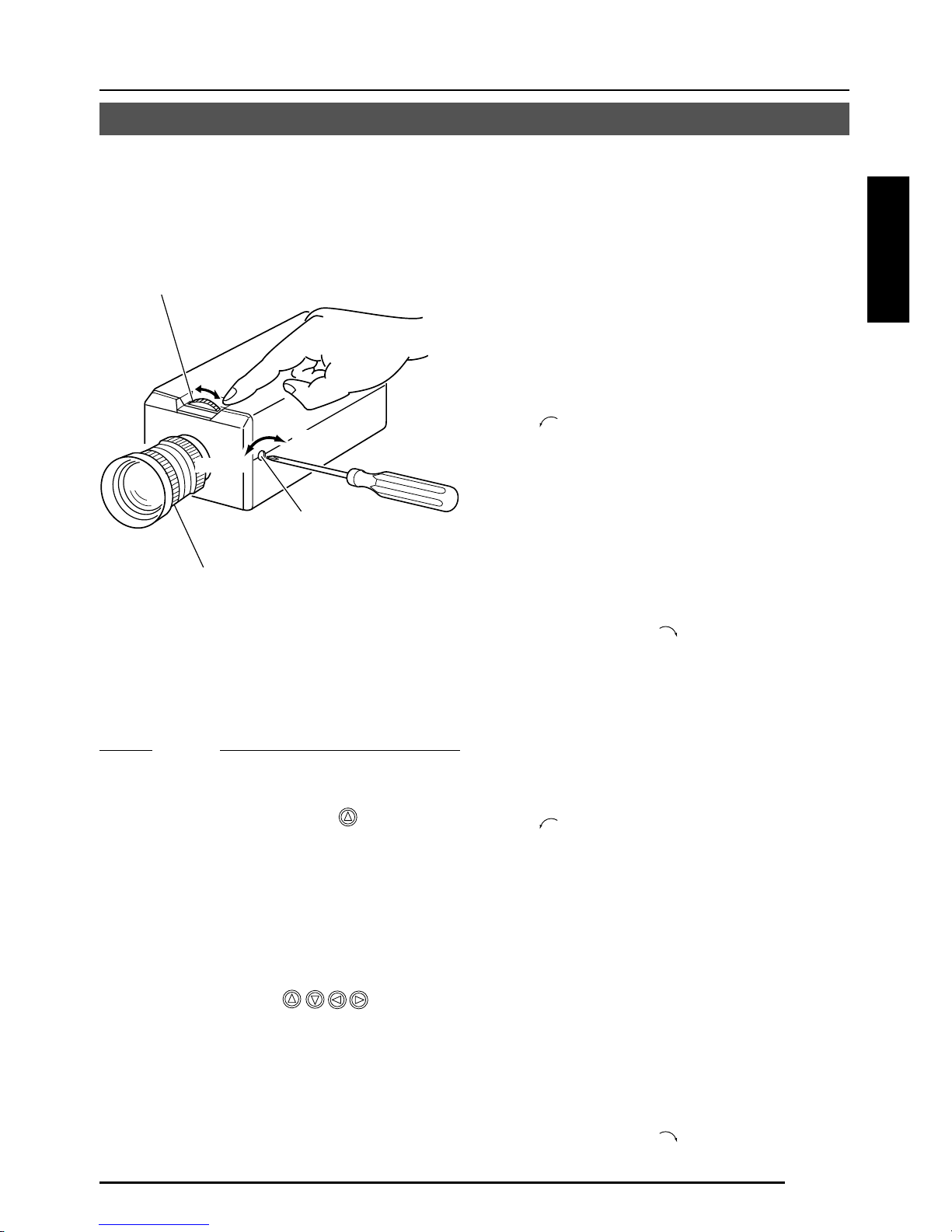
G-19
Deutsch
Einstellen der Schnittweite
• Für ein Fixfokus-Objektiv
Wenn der Fokus nicht durch Drehen des
Fokussierrings am Objektiv korrekt eingestellt
werden kann, so stellen Sie die Schnittweite
wie folgt ein:
1.
Lösen Sie die Feststellschraube für die
Schnittweite durch Drehen mit einem
Schraubenzieher gegen den Uhrzeigersinn
(
) .
2.
Nehmen Sie ein nahes Muster auf.
3.
Drehen Sie den Fokussierring der
Kamera zu ⬁.
4.
Drehen Sie den Einstellring für die
Schnittweite, um auf den besten Punkt
zu fokussieren.
5.
Ziehen Sie die Feststellschraube für die
Schnittweite durch Drehen im
Uhrzeigersinn (
) an.
• Für ein Zoomobjektiv
Wenn das Bild beim Zoomen (Tele/Weitwinkel)
unscharf wird, so stellen Sie die Kamera wie
folgt ein:
1.
Lösen Sie die Feststellschraube für die
Schnittweite durch Drehen mit einem
Schraubenzieher gegen den Uhrzeigersinn
(
) .
2.
Nehmen Sie eine verhältnismäßig
dunkle Szene mit dünnen Linien auf.
3.
Stellen Sie das Objektiv auf die
maximale Teleposition ein und stellen
Sie den Fokus scharf ein.
4.
Stellen Sie das Objektiv auf die
maximale Weitwinkelposition ein und
drehen Sie den Schnittweitenring, um
den Fokus einzustellen.
(Wiederholen Sie die Schritte
3
und
4
zwei- oder dreimal.)
5.
Ziehen Sie die Feststellschraube für die
Schnittweite durch Drehen im
Uhrzeigersinn (
) an.
Einstellen der Schnittweite
Achten Sie darauf, die Schnittweite einzustellen, wenn Sie die Anbringungsmethode für das
Objektiv ändern oder ein anderes Objektiv verwenden.:
MEMO
• Einstellmodus für Objektivscharfeinstellung
Drücken Sie zum Zeitpunkt der
Scharfeinstellung die Taste an der Seite
des Gerätes mindestens eine Sekunde
lang, um die Objektivblende zu öffnen und
Scharfeinstellung zu erleichtern. Zu dieser
Zeit wird “LENS FOCUS ADJUSTMENT
MODE” auf dem Monitorbildschirm
angezeigt.
Drücken Sie nach beendigter Einstellung
eine der Tasten
, um den
Scharfeinstellungsmodus zu annullieren.
• Wenn das Objekt hell ist, ermöglicht die
Verwendung eines ND-Filters genauere
Einstellung der Schnittweite. (Das ND-Filter verringert die Menge des in das
Objektivs eintretenden Lichtes gleichförmig
über den gesamten Wellenlängenbereich.)
Feststellschraube für
die Schnittweite (M2.6)
Einstellring für die
Schnittweite
Fokussierring des
Objektivs
B
F
L
O
C
K
Anziehen
Lösen
Page 60

G-20
Einstellung für automatischen Weißabgleich
1.
Stellen Sie ein weißes Objekt unter den
gleichen Beleuchtungsbedingungen wie
das aufzunehmende Objekt auf und
Zoomen Sie so, dass der gesamte
Bildschirm weiß ist.
2.
Wenn die Taste AWC etwa eine
Sekunde lang gedrückt wird, so wird der
Weißabgleich für das aufzunehmende
Objekt eingestellt.
3.
Während die Funktion für automatischen
Weißabgleich tätig ist, wird “AWC OP-
ERATION” angezeigt (für etwa 0,5 sec).
Wenn der angemessene Weißabgleich
erreicht worden ist, wird “AWC OK”
angezeigt.
4.
Anzeige von Fehlermeldungen
● NG: OBJECT
Dies wird angezeigt, wenn das Objekt
nicht genug weiße Farbe hat oder
wenn die Farbtemperatur nicht
angemessen ist.
Stellen Sie den Weißabgleich erneut
durch Aufnahme eines weißen Objekts
über den gesamten Bildschirm auf.
● ERROR: LOW LIGHT
Dies wird angezeigt, wenn zu wenig
Licht vorhanden ist. Sorgen Sie für
bessere Beleuchtung und führen Sie
dann erneut Weißabgleich durch.
● ERROR: HIGH LIGHT
Dies wird angezeigt, wenn das Licht
zu hell ist. Verringern Sie die
Lichtmenge und führen Sie dann
erneut Weißabgleich durch.
CAMERA
SETUP
SET
MENU
EXT TERM-OFF
INT/GL
DUPLEX
RX TERM-OFF
NOT USED
ON
LL
SIMPLEX
ON
VIDEO
DC
IRIS
AWC
Taste AWC
AWC OK
Anzeige des Ergebnisses
AWC OPERATION
Während des Betriebs
AWC NG : OBJECT
Objektfehler
AWC ERROR : LOW LIGHT
Schwache Beleuchtung
AWC ERROR : HIGH LIGHT
Zu starke Beleuchtung
Jede Lichtquelle hat ihre eigene Farbtemperatur. Wenn die Hauptlichtquelle geändert wird,
sollte deshalb der Weißabgleich durch Drücken der Taste AWC neu eingestellt werden.
ANSCHLUSS/INSTALLATION
Page 61

G-21
MENÜEINSTELLUNG
Einstellen des Menüs
CAMERA
SETUP
SET
MENU
EXT TERM-OFF
INT/GL
DUPLEX
RX TERM-OFF
NOT USED
CAMERA
SETUP
SET
MENU
ON
LL
SIMPLEX
ON
VIDEO
DC
IRIS
AWC
1.
Drücken Sie die Taste MENU.
Der Bildschirm MENU erscheint.
2.
Stellen Sie den Cursor (>) mit
den Tasten
, auf das
gewünschte Untermenü.
3.
Drücken Sie die Taste SET.
Der Bildschirm für das gewünschte
Untermenü wird angezeigt.
4.
Verwenden Sie die Tasten ,
um den Cursor (>) auf einen
gewünschten Punkt zu stellen.
5.
Ändern Sie den Einstellwert mit
den Tasten
, Bei Änderung
des Einstellwerte wird die
Änderungsmarkierung (∗).
Wenn Sie die Einstellwerte für andere
Punkte ändern wollen, so wiederholen
Sie die obigen Punkte 2. bis 5.
6.
Drücken Sie die Taste MENU.
Der Bildschirm kehrt zum vorherigen
Bildschirm (Bildschirm MENU) zurück.
7.
Drücken Sie die Taste MENU.
Der Bildschirm kehrt zum normalen
Bildschirm zurück (Verlassen der
Menüanzeige).
* Wenn die Einstellung mit RM-P2580
durchgeführt wird, so verwenden Sie den
Joystick anstatt der Tasten
, , und
.
Taste MENU
Taste SET
MENU
SYNC ADJUST
VIDEO ADJUST
MOD E ESLECT
ALC SETT I NGS
COMMUN I CAT ION
MA IN TEN NACE
MOT I ON
D
E
TECT
..
FACTORY SETTI NGS ..
..
..
..
..
..
..
LACSETTINGS
IIRSLEVEL NORMAL
AEVRAEG:PEAK 82:
ACGMODE
MODE
2dB0
SUTHTERExDR/
NRMALO
LUX
LO O FF
PIORRITY –––
BCLOFF
SNSEEUP OFF
LACSETTINGS
AEVRAEG:PEAK 82:
ACGMODE
2dB0
SUTHTERExDR/
NRMALO
I∗IRS LEVEL -5
OFF
PIORRITY –––
BCLOFF
SNSEEUP OFF
MODE
LUX
LO
LACSETTINGS
IIRSLEVEL NORMAL
AEVRAEG:PEAK 82:
ACGMODE
MODE
2dB0
SUTHTERExDR/
NRMALO
LUX
LO O FF
PIORRITY –––
BCLOFF
SNSEEUP OFF
Page 62

G-22
MENU
SYNC ADJUST
VIDEO ADJUST
MOD E ESLECT
ALC SET T I NGS
COMMUN I CAT ION
MA I N TE N NACE
MOT I ON
D
E
TECT
SYNC DAJUST
VPHASE 0
HPHASE 0
SC ECOARS 0
SC F INE 1 28
DEVI O ADJUST
WH TE BA L E AT WNC
A
I
CO OUR LE NORMALEL
V
L
EN ANCE LE NORMALEL
V
H
PEESTAL LE NORMALEL
V
D
AUOBLAC K OFFTL
C
T
TIMO O N DE TECT
MO E OFFD
LE EL NORMALV
AR A EDIE
ALRMTI EM10sA
DEONSTRATIN
O
M
WH I T E BALANCE CONTROL
AWC SE T . .
RB
::
MG
::
g
INMA TE NANCE
CC SP OT. .D
DCC SPOT
CA ELNC
E
heat up 30min in advance
need Lens–cap to execute
XCTEUE
.
.
..
FACTORY SETTI NGS..
..
..
..
..
..
..
T..
MENÜEINSTELLUNG
Ablauf der Menübildschirme
Seite 24
Seite 28
Seite 30
Seite 33
Seite 35
Seite 36
Seite 36
Page 63

G-23
Seite 24
Seite 29
Seite 31
Seite 34
Seite 32
CTFA ORY SE NGSTT I
CA CELN
CL A W I(HOUT T I T LE )RTE
C
DATA CLEARED
LA()RALLE
LACSETTINGS
IIRSLEVEL NORMAL
AEVRAEG:PEAK 82:
ACGMODE
MODE
2dB0
SUTHTERExDR/
NRMALO
LUX
LO O FF
PIORRITY –––
BCLOFF
SNSEEUP OFF
MODE SE L EC T
CAMERA T I TL E ED I T. .
REV ERSE MODE OFF
HL I MODE OFF
ALM .T I TLE S ZEI DOUBLE
ALA RM COLOUR WH I TE
D.ZOOM MAX x 2
MMCO UNICAT ION
S T L E P TO PY
MA H NE DII – – –C
SHUT T RE/ExDR
SHUTTER SPEED
SPEED
1 120/
–––
–––
–––
FAST L IMIT
EDxER
EDxR
LLEV
M.
CAMERA T
ITL
E
’
ДЦ ВК ОФЫЗС
длп цьвко ф
Ü
ыбйну
аим тщзсЯ
¡¿
ú
0123456789
:-/
.,
ABCDE K LMNOPFGH I J
QRSTUVWXYZ
abcde klmnopf g hi j
qrstuvwxyz
TDislayitle
WIDE TELE
Seite 31
Seite 25
Page 64

G-24
Punkt Funktionen und Einstellwerte Ausgangswert
V PHASE
H PHASE
SC COARSE
SC FINE
Hiermit wird die vertikale Synchronisation auf die einer
anderen Kamera eingestellt, wenn der Wahlschalter für das
Synchronisationssystem an der Seite auf LL gestellt ist. (Nur
für Bereiche mit 50 Hz-Stromversorgung.)
Wenn dieser Schalter nicht auf LL gestellt ist, wird “---”
angezeigt und der Einstellwert kann nicht geändert werden.
[Einstellwert: –156 bis 0 bis 156]
Hiermit wird die horizontale Synchronisation auf die einer
anderen Kamera eingestellt, wenn der Wahlschalter für das
Synchronisationssystem an der Seite auf INT/GL gestellt ist.
Wenn keine externen Signale eingegeben werden, wird “---”
angezeigt und der Einstellwert kann nicht geändert werden.
[Einstellwert: -16 bis 0 bis 16]
Grobeinstellung der SC-Phase in Genlock-Betrieb. Die SC-Phase
kann um bis zu 90° in jeder Richtung variiert werden. Führen Sie
Einstellung mit Bezug auf eine andere Kamera (oder ein anderes
System) und zusammen mit der Einstellung SC FINE durch.
Stellen Sie SC COARSE und SC FINE nur nach Einstellung
von H PHASE ein.
Wenn der Schalter nicht auf GL gestellt ist, wird “---”
angezeigt und der Einstellwert kann nicht geändert werden.
[Einstellwerte: 0°, 90°, 180°, 270°]
Feineinstellung der SC-Phase in Genlock-Betrieb.
Wenn der Schalter nicht auf GL gestellt ist, wird “---”
angezeigt und der Einstellwert kann nicht geändert werden.
[Einstellwerte: 0 bis 255]
MENÜEINSTELLUNG
Bildschirm SYNC ADJUST
Hier werden die Einstellungen in Bezug auf die Synchronisation durchgeführt.
0
/
0
0°
128
Bildschirm ALC SETTINGS
Punkt Funktionen und Einstellwerte Ausgangswert
IRIS LEVEL
AVERAGE:
PEAK
Hierdurch werden automatische Einstellungen entsprechend der Helligkeit durchgeführt.
Einstellung des Helligkeitspegels des Videosignals.
• Zum Verringern des Helligkeitspegels ... Den Wert verringern.
• Zum Erhöhen des Helligkeitspegels ... Den Wert erhöhen.
[Einstellwert: -50 bis NORMAL bis 5]
Einstellung der Belichtungsentdeckung als Verhältnis
zwischen dem Durchschnittswert und dem Spitzenwert.
• Großer Durchschnittswert (AVERAGE): Erhöhen Sie den
Durchschnittswert (AVERAGE), wenn Bereiche außerhalb
der hervorgehobenen Bereiche des Bildschirms dunkel sind
und schlecht aussehen. (Beispiel: 10:0)
• Großer Spitzenwert (PEAK): Erhöhen Sie den Spitzenwert
(PEAK), wenn es in den hervorgehobenen Bereichen des
Bildschirms zu Lichthofbildung kommt. (Beispiel: 5:5)
[Einstellwerte: 10:0, 9:1, 8:2, 7:3, 6:4, 5:5]
NORMAL
8 : 2
Page 65

G-25
NORMAL
1/120
Punkt Funktionen und Einstellwerte Ausgangswert
SHUTTER/
ExDR
* Wenn der Punkt SHUTTER/ExDR auf NORMAL gestellt ist, können die folgenden
Punkte (SHUTTER SPEED, FAST LIMIT, ExDR LEVEL und M.ExDR SPEED) nicht
geändert werden.
SHUTTER
SPEED
Hiermit werden der Verschluss und der erweiterte Dynamikbereich
(ExDR) eingestellt.
Die Verwendung einer elektronischen Verschlussfunktion ermöglicht
Aufnahme mit angemessener Helligkeit, da größere Helligkeit zu
einer kürzeren Verschlusszeit führt.
Die Funktion ExDR erlaubt selbst die Aufnahme eines Objekts mit
unterschiedlicher Lichtflussdichte durch Kombination eines mit einer
Verschlusszeit von 1/100 sec aufgenommenen Bildes mit einem mit einer
kurzen Verschlusszeit aufgenommenen Bild.
NORMAL: Hierbei ist die Verschlusszeit auf 1/50 sec fixiert.
Die Funktion ExDR ist nicht wirksam.
MANUAL: Hierbei wird die Verschlusszeit entsprechend dem Punkt
SHUTTER SPEED am Bildschirm SHUTTER
eingestellt.
Die Funktion ExDR ist nicht wirksam.
Wenn die Funktion SENSE UP aktiv ist, kann MANUAL
nicht gewählt werden. (Es erfolgt keine Anzeige in MENU.)
AUTO: Hierbei wird die Verschlusszeit automatisch
entsprechend der Helligkeit umgeschaltet.
Die Funktion ExDR ist nicht wirksam.
Der Punkt FAST LIMIT des Bildschirms SHUTTER/
ExDR bestimmt die kürzeste Verschlusszeit.
M.ExDR: Dies wird verwendet zur Aufnahme eines Objektes mit
unterschiedlicher Lichtflussdichte auf dem Bildschirm
unter fixierten Beleuchtungsbedingungen usw.
Im Modus ExDR stellt der Punkt M.ExDR.SPEED am
Bildschirm SHUTTER (ExDR) die kurze Verschlusszeit
für Kombinationsbilder ein. Einstellung ist nur möglich,
wenn die Punkte BLC und SENSE UP ausgeschaltet sind
(OFF). Weiterhin stellt ExDR LEVEL den Signalpegel für
die kurze Verschlusszeit für Kombinationsbilder ein.
A.ExDR: Dies wird verwendet, wenn die Objekte unterschiedliche
Lichtflussdichten haben und Tag und Nacht in einer
Situation verwendet werden, wo Objekte in Gebäuden
und im Freien gemischt vorhanden sind usw.
Im Modus ExDR ändert sich die Kombinationsverschlusszeit
automatisch entsprechend dem Kontrast des Objekts. Diese
Einstellung wird für Aufnahme eines Objektes mit sich
ändernder Helligkeit durchgeführt.
Einstellung ist nur möglich, wenn der Punkt BLC
ausgeschaltet ist (OFF). Weiterhin stellt ExDR LEVEL
den Signalpegel für die kurze Verschlusszeit für
Kombinationsbilder ein.
Memo
• Stellen Sie bei Verwendung eines manuellen Objektivs nicht auf
A.ExDR.
• Wenn der Modus M.ExDR oder der Modus A.ExDR verwendet
wird, kann die Grenze zwischen einem hellen und einem dunklen
Teil farbig werden (Zyan, Orange usw.), aber dies ist keine
Fehlfunktion.
Hiermit wird bei Einstellung auf MANUAL eine Verschlusszeit eingestellt.
Der Einstellwert für AUTO, M.ExDR, A.ExDR wird als “---” angezeigt
und kann nicht geändert werden.
[Einstellwerte: 1/120, 1/250, 1/500, 1/1000, 1/2000, 1/4000 und 1/
10000]
Page 66

G-26
Punkt Funktionen und Einstellwerte Ausgangswert
FAST LIMIT
ExDR
LEVEL
M.ExDR
SPEED
AGC MODE
LOLUX MODE
SENSE UP
1/100000
NORMAL
1/4000
20dB
OFF
OFF
Bildschirm ALC SETTINGS (fortgesetzt)
MENÜEINSTELLUNG
Hiermit wird die kürzeste Verschlusszeit bei Einstellung von AUTO
eingestellt. Der Einstellwert für MANUAL, M.ExDR, A.ExDR wird
als “---” angezeigt und kann nicht verändert werden. Je kürzer
die Verschlusszeit wird, um so mehr werden die für CCDs
eigentümlichen Eigenschaften betont.
[Einstellwerte: 1/1000, 1/2000, 1/4000, 1/10000, 1/20000, 1/40000, 1/100000]
Hiermit wird der Signalpegel für die kombinierte kurze
Verschlusszeit im ExDR-Modus eingestellt. Einstellung erfolgt
entsprechend der Helligkeit des Objekts.
Achten Sie bei Verwendung von M.ExDR darauf, vorher M.ExDR
SPEED einzustellen.
Wenn der Punkt SHUTTER/ExDR auf MANUAL oder AUTO
gestellt ist, erscheint “---” und die Einstellung ist unwirksam.
Für höhere Priorität der dunklen Bildteile … Erhöhen Sie den Wert.
Für höhere Priorität der hellen Bildteile … Verringern Sie den Wert.
[Einstellwert: -5 bis NORMAL bis 5]
Memo
• Bei Objekten mit sehr großem Unterschied in der Lichtflussdichte
ändert sich das Bild manchmal auch bei Änderung von ExDR
LEVEL nicht. Dies ist jedoch eine Charakteristik des Gerätes
und keine Fehlfunktion.
Hiermit wird die kombinierte kurze Verschlusszeit eingestellt, wenn
ExDR auf M.ExDR eingestellt ist. Stellen Sie die Verschlusszeit so
ein, dass ein Objekt mit einer hohen Lichtflussdichte (im Freien usw.)
am schärfsten angezeigt wird. Während MANUAL, AUTO bzw.
A.ExDR erfolgt Anzeige als “---” und Einstellung ist nicht möglich.
[Einstellwerte: 1/500,1/1000, 1/2000, 1/4000, 1/10000, 1/20000]
Hiermit wird die maximale Verstärkung für AGC (automatische
Verstärkungsregelung) eingestellt.
OFF (Aus): Wenn die AGC-Funktion nicht verwendet wird.
10dB: Wenn die Lichtenergie nicht ausreichend ist.
20dB: Wenn die Lichtenergie stark nicht ausreichend ist.
SUPER: Wenn die Lichtenergie selbst bei Einstellung auf 20dB
nicht ausreichend ist.
• Wenn die Verstärkung erhöht wird, werden dunkle Teile des
Bildschirms grob.
• Bei Einstellung auf SUPER kann bei drastischen
Pegeländerungen Betriebszeit verbraucht werden.
Selbst wenn der Punkt AGC MODE auf SUPER LOLUX gestellt ist, erfolgt
die Einstellung, wenn die Helligkeit nicht ausreichend ist.
(Dies funktioniert unabhängig von dem durch AGC MODE eingestellten Wert.)
OFF: LOLUX MODE funktioniert nicht.
ON: LOLUX MODE funktioniert. (+6 dB)
Durch diesen Punkt wird die Empfindlichkeit automatisch erhöht,
wenn das Objekt dunkel wird.
Bei X32 AUTO wird die Empfindlichkeit automatisch und im Vergleich
zum Standard kontinuierlich bis auf den 32-fachen Wert erhöht.
Mit zunehmender Empfindlichkeit wird die Verschlusszeit länger,
was in unnatürlicher Bewegung resultiert.
Wenn SHUTTER/ExDR auf MANUAL oder M.ExDR eingestellt
ist, erscheint “---” und die Funktion SENSE UP ist unwirksam.
[Einstellwerte: OFF, X2 AUTO, X4 AUTO, X8 AUTO, X16 AUTO, X32 AUTO]
Memo
•
Wenn der Faktor von SENSE UP erhöht wird, kann der Bildschirm grob oder weißlich
werden, oder weißliche Flecken können erscheinen, aber dies ist keine Störung.
Page 67

G-27
Punkt Funktionen und Einstellwerte Ausgangswert
PRIORITY
BLC
MOTION
OFF
Dieser Punkt stellt die Reihenfolge ein, in der AGC abnimmt
und die Verschlusszeit länger wird, wenn die Helligkeit des
Objekts abnimmt.
Wenn der Punkt AGC MODE oder der Punkt SENSE UP
auf OFF gestellt ist, wird “---” angezeigt und Einstellung
ist nicht möglich.
MOTION: Bewegung erhält Vorrang.
Dies ist angemessen für ein Objekt mit
schneller Bewegung, da AGC (automatische
Verstärkungssteuerung) mit Vorrang
funktioniert, wenn das Objekt dunkel wird.
PICTURE: Das Bild erhält Vorrang.
Wenn das Objekt dunkel wird, funktioniert
SENSE UP mit Vorrang (die Empfindlichkeit
wird größer), und ein angemessenes Bild erhält
Vorrang.
Einstellung der Ausgleichsfunktion für Gegenlicht.
Einstellung erfolgt, wenn sich eine helle Lichtquelle usw.
in der gleichen Richtung wie das Objekt befindet.
Wenn der Punkt SHUTTER/ExDR auf M.ExDR oder
A.ExDR eingestellt ist, wird “---” angezeigt und BLC
funktioniert nicht.
OFF: Die Ausgleichsfunktion für Gegenlicht ist
ausgeschaltet.
AREA 1 bis AREA 4 (Bereich 1 bis 4): Wenn die Taste
SET gedrückt wird, werden die Bereiche für fixierte
Belichtungsmessung angezeigt. Wählen Sie einen dieser
vier Bereiche. (Die auf dem Bildschirm angezeigten
Positionen sind ungefähre Positionen. Führen Sie die
erforderlichen Einstellungen nach Überprüfung und
Bestätigung der Funktionen an tatsächlichen Bildern
durch.)
EDIT 1 und EDIT 2: Wenn die Taste SET gedrückt wird,
werden die Benutzer-Lichtmessbereiche angezeigt.
Wählen Sie einen der zwei Bereiche.
Bildschirm BLC EDITING auf Seite 32.
Lichtmess
bereich
Lichtmess
bereich
Lichtmess
bereich
Lichtmess
bereich
Lichtmess
bereich
Aus Bereich 1 Bereich 2 Bereich 3 Bereich 4
Page 68

G-28
Punkt Funktionen und Einstellwerte Ausgangswert
WHITE
BALANCE
COLOUR
LEVEL
ENHANCE
LEVEL
PEDESTAL
LEVEL
AUTO
BLACK
CTL
AT W
NORMAL
NORMAL
NORMAL
OFF
Bildschirm VIDEO ADJUST
MENÜEINSTELLUNG
Einstellungen für Videosignale werden durchgeführt.
Wahl der Einstellungsfunktion für den Weissabgleich. Der
Weissabgleich kann für Licht im
Farbtemperaturbereich von 2500 K bis 8000 K
manuell oder automatisch durchgeführt werden.
• ATW: Weissableichmodus mit automatischer
Verfolgung.
Hierdurch wird automatisch der Weissabgleich
entsprechend der Farbtemperatur des Lichtes
eingestellt.
• AWC: Modus für automatische Steuerung des
Weissableichs. Wenn die Taste SET gedrückt
wird, erscheint der Einstellungsbildschirm.
( Siehe Seite 33.)
Zum Einstellen des Farbpegels des Videosignals.
• Für hellere Farben … Den Wert verringern.
• Für dunklere Farben … Den Wert erhöhen.
[Einstellwert: -5 bis NORMAL bis 5]
Zum Einstellen des Konturbetonungspegels des
Videosignals.
• Für härtere Bilder … Den Wert erhöhen.
• Für weichere Bilder … Den Wert verringern.
[Einstellwert: -5 bis NORMAL bis 5]
Zum Einstellen des Schwarzwertimpulspegels des
Videosignals.
• Für ein helleres Bild … Den Wert erhöhen.
• Für ein dunkleres Bild … Den Wert verringern.
[Einstellwert: -5 bis NORMAL bis 5]
Diese Einstellung wird durchgeführt, wenn ein dunkler Teil des
Bildes auch bei Anheben der Verstärkung durch AGC
(automatische Verstärkungssteuerung) schlecht zu sehen ist.
ON: Wenn der Schwarzpegel des Bildsignals niedrig ist,
wird der Schwarzwertimpulspegel, der zum
Standard für Schwarz wird, automatisch
angehoben, wodurch ein schwarzer Teil besser
gesehen werden kann.
OFF: AUTO BLACK ist nicht wirksam.
Memo
• Wenn PEDESTAL LEVEL auf 5 eingestellt ist, kann keine
Funktion erfolgen, selbst wenn AUTO BLACK CTL auf
ON gestellt ist.
• Wenn AGC MODE auf OFF gestellt ist, kann keine
Funktion erfolgen, selbst wenn AUTO BLACK CTL auf
ON gestellt ist.
Page 69

G-29
Bildschirm MODE SELECT
Titel, Bildumkehrungen usw. werden eingestellt.
Punkt Funktionen und Einstellwerte Ausgangswert
CAMERA
TITLE EDIT
REVERSE
MODE
HLI-MODE
ALM.TITLE
SIZE
ALARM
COLOUR
D.ZOOM
MAX
–
OFF
OFF
DOUBLE
WHITE
x2
ALARM
ALARM
NORMAL (Normal) DOUBLE (Doppelt)
Zeigen Sie den Bildschirm CAMERA TITLE; EDIT an.
( Seite 34)
Einstellungen für Bildumkehr.
OFF: Das Bild wird nicht umgekehrt.
R-L: Das Bild wird horizontal umgekehrt.
U-D: Das Bild wird vertikal umgekehrt.
ALL: Das Bild wird horizontal und vertikal umgekehrt.
Der hellerleuchtete Teil des Bildes wird schwarz gemacht,
um die Teile um den hellerleuchteten Teil herum besser
sichtbar zu machen.
Auf HIGH stellen, wenn es viele hellerleuchtete Teile gibt.
[Einstellwerte: OFF, LOW, MIDDLE, HIGH]
Einstellen der Größe von im Alarmfall angezeigten
Schriftzeichen.
Stellt die Farbe von Alarmtiteln ein.
[Einstellwerte: WHITE (Weiß), YELLOW (Gelb), CYAN
(Zyan), GREEN (Grün)]
Diese Funktion stellt die maximale Zoomrate für
elektronisches Zoomen ein.
[Einstellwerte: x1, x2, x4, x6, x8, x10]
Memo
• Die elektronische Zoomfunktion kann nur durch den
Kommunikationsbefehl von exklusiven Steuereinheiten
(RM-P2580 usw.) verwendet werden.
• Bitte beachten Sie, dass sich die Bildqualität bei
elektronischem Zoomen verschlechtert, da dies digitale
Bildverarbeitung beinhaltet.
• Wenn die elektronische Zoomrate erhöht wird, kann es
zu Verschwimmen in der oberen linken Mitte des
Bildschirms kommen. Dies ist eine Charakteristik des
Hauptgerätes und keine Fehlfunktion.
Page 70

G-30
Punkt Funktionen und Einstellwerte Ausgangswert
MODE
LEVEL
AREA EDIT
ALARM TIME
DEMONSTRATION
OFF
NORMAL
–
10s
–
MENÜEINSTELLUNG
Bildschirm MOTION DETECT
Hiermit wird die Bewegungsentdeckungsfunktion ein- oder
ausgeschaltet.
OFF: Die Bewegungsentdeckungsfunktion ist unwirksam.
ON: Die Bewegungsentdeckungsfunktion ist wirksam.
Einstellen des Pegels, der Bewegung entdeckt.
Wenn der Punkt MODE auf OFF gestellt ist, wird “- - -”
angezeigt und Einstellungen können nicht geändert werden.
Für Funktion mit großen Signalpegeländerungen … Den
Wert verringern.
Für Funktion mit kleinen Signalpegeländerungen … Den
Wert vergrößern.
[Einstellwert: -5 bis NORMAL bis 5]
Einstellen des Bereichs, in dem die
Bewegungsentdeckungsfunktion arbeitet.
(墌 Seite 35)
Einstellen der Ausgabezeit für die Alarmsignalausgabe
vom Anschluss AUX und die Anzeige von „ALARM“ auf
dem Bildschirm, wenn Bewegung entdeckt wird.
Wenn der Punkt MODE auf OFF gestellt ist, wird “- - -”
angezeigt und Einstellungen können nicht geändert
werden.
[Einstellwerte: OFF (Aus), 5 s, 6 s, 7 s, 8 s, 9 s, 10 s, 15 s,
20 s, 30 s, 1 min]
Memo
Wenn der Punkt MODE auf OFF gestellt ist, wird nur das
Alarmsignal am Anschluss AUX abgegeben, und „ALARM“
wird nicht auf dem Bildschirm angezeigt.
Diese Einstellung wird zur Überprüfung und Bestätigung
der Bewegungsentdeckungsfunktion verwendet. Der
Entdeckungsbereich wird grau angezeigt.
(墌 Seite 35)
Einstellungen für die Bewegungsentdeckungsfunktion, bei der Alarmsignale abgegeben
werden, wenn eine Bewegung im Bild vorhanden ist. Alarmsignale werden von den
Hilfsklemmen an der Rückseite ausgegeben.
Page 71

G-31
Punkt Funktionen und Einstellwerte Ausgangswert
FACTORY
SETTINGS
Die Einstellwerte werden als Ausgangswerte zurückgegeben.
Die im Menü eingestellten Werte werden als Ausgangswerte
zurückgegeben.
CANCEL : Es wird kein Ausgangswert zurückgegeben.
CLEAR : Einstellwerte, ausgenommen Titel, werden
(WITHOUT TITLE)
als Ausgangswerte zurückgegeben.
CLEAR (ALL) : Alle Einstellwerte, einschließlich Titel, werden
als Ausgangswerte zurückgegeben.
Wählen Sie den entsprechenden Einstellwert und drücken Sie
die Taste SET. „DATA CLEARED“ (Daten gelöscht) wird dann etwa
3 Sekunden klang angezeigt. Achten Sie darauf, die
Stromversorgung nicht auszuschalten, während die Anzeige noch
angezeigt wird.
Memo
Wenn Einstellungen durch übertragene Befehle gemacht werden,
erfolgt durch den Inhalt des Menüs COMMUNICATION keine
Rückkehr zu den Werkseinstellungen.
–
Bildschirm COMMUNICATION
Punkt Funktionen und Einstellwerte Ausgangswert
STYLE
MACHINE ID
Einstellungen für die Anschlüsse für Steuersignale an der Rückseite.
Wenn die Einstellung geändert wird, so achten Sie unbedingt darauf, die Stromversorgung
aus- und wieder einzuschalten.
P TO P
– – –
Bildschirm FACTORY SETTINGS
Einstellung eines Kommunikationssystems entsprechend dem
verwendeten System.
P TO P (Punkt zu Punkt)
Diese Einstellung wird verwendet, wenn eine Fernbedienung eine
Kamera steuert.
M.DROP (Mehrfachanschluss)
Diese Einstellung wird verwendet, wenn eine Fernbedienung
mehrere Kameras steuert.
Diese Einstellung wird verwendet, wenn der Punkt STYLE auf
M.DROP eingestellt ist. Diese Nummer identifiziert einzelne
Kameras in einer Gruppe. Wenn eine ID-Nummer in einem System
doppelt vorhanden ist, kann keine angemessene Funktion
realisiert werden.
Kombinierte Verwendung mit RM-P2580 erfordert Einstellung
zusammen mit der Videoeingangsnummer von RM-P2580.
Wenn der Punkt STYLE auf P TO P eingestellt ist, wird “---”
angezeigt und Einstellungen können nicht geändert werden.
[Einstellwert: 1 bis 99]
Punkt Funktionen und Einstellwerte Ausgangswert
CCD SPOT
Weißpunktausgleich wird durchgeführt.
Weiße Punkte des CCD-Elements Die weißen Punkte auf dem
Bildschirm, die für CCD-Elemente charakteristisch sind, können
verringert werden.
Seite 36 “Weißpunktausgleich”
–
Bildschirm MAINTENANCE
Page 72

G-32
Bildschirm BLC EDITING
MENÜEINSTELLUNG
Der Lichtmessbereich für Gegenlichtausgleich kann frei eingestellt werden. Die zwei
Bildschirme EDIT 1 und EDIT 2 können eingestellt werden.
CAMERA
SETUP
SET
MENU
AWC
Bildschirm EDIT 1
Lichtmess
bereich
Lichtmessbereich
Taste SET
Taste SET
Taste SET
Taste MENU
Bildschirm EDIT 2
1.
Stellen Sie den Punkt BLC am
Bildschirm ALC SETTING auf EDT1.
2.
Drücken Sie die Taste SET.
Der Bildschirm EDIT 1 wird angezeigt.
3.
Stellen Sie die Oberseite und die
linke Seite des Messbereichs mit
den Tasten , , und ein.
Die Seiten mit den Markierungen
und können geändert werden.
4.
Drücken Sie die Taste SET.
Die veränderbaren Seiten des
Messbereichs bewegen sich zur rechten
Seite und zur Basis.
5.
Stellen Sie die Basis und die rechte
Seite des Messbereichs mit den
Tasten , , und ein.
Wenn die Taste SET erneut gedrückt
wird, kehren die zwei veränderbaren
Seiten des Messbereichs zur oberen
und zur linken Seite zurück. (Der
Bildschirm EDIT 2 kann auf die gleiche
Weise eingestellt werden.)
6.
Drücken Sie nach beendigter
Einstellung die Taste MENU.
Der Bildschirm kehrt zum Bildschirm
ALC SETTING zurück.
* Stellen Sie zur Verwendung des
eingestellten Messbereichs den Punkt BLC
auf EDIT 1 oder EDIT 2.
LACSETTINGS
IIRS LEVEL NORMAL
AEV RAGE : PEAK 8 2:
SUTHTERExD
LUX
R/NRMALO
SPEURLO OFF
PIORRITY MTIONO
BCL
EDIT 1
SNSEEUP OFF
ACGMODE 2dB0
Page 73

G-33
Manuelle Einstellung des Weissableichs
Wenn automatische Einstellung des Weissableichs zu einem „rötlichen Bildschirm“ usw. führt,
so stellen Sie den Weissabgleich manuell ein.
1.
Stellen Sie den Punkt WHITE
BALANCE auf dem Bildschirm
VIDEO ADJUST auf AWC und
drücken Sie die Taste SET.
• Der Bildschirm WHITE BALANCE
CONTROL erscheint auf dem Monitor.
2.
Wählen Sie den einzustellenden
Farbton. (R/B oder Mg/G)
Drücken Sie die Taste
oder .
3.
Stellen Sie den Farbton ein.
Press the
or button.
• Die Anzeige “ı” bewegt sich
entsprechend der Einstellung. Wenn
eine Einstellung geändert wird,
erscheint die Markierung “+” an der
ursprünglichen Position.
4.
Beendigen Sie die Einstellung
des Weissableichs.
Durch Drücken der Taste MENU erfolgt
Rückkehr zum Bildschirm VIDEO ADJUST.
DEVI O ADJUST
WH T E BA L E AWCNC
A
I
CO OUR L E NORMALEL
V
L
EN ANCE LE NORMALEL
V
H
PEESTAL LE NORMALEL
V
D
AUOBLACK OFFTL
C
T
WH I T E BALANCE CONTROL
AWC SE T. .
RB
::
MG
::
g
Bildschirm VIDEO ADJUST
Bildschirm WHITE BALANCE CONTROL
CAMERA
SETUP
SET
MENU
AWC
Taste SETTaste MENU
Page 74

G-34
1.
Wählen Sie den Punkt CAMERA
TITLE am Bildschirm MODE
SELECT und drücken Sie die
Taste SET.
Der Bildschirm CAMERA TITLE wird
dann angezeigt.
2.
Wählen Sie das erste Zeichen
mit den Tasten
, , und
aus dem Zeichenbereich.
Das gewählte Zeichen wird blinkend
angezeigt.
3.
Drücken Sie die Taste SET.
Das erste Zeichen wird fixiert und der
blinkende Titeleingabebereich bewegt
sich zum zweiten Zeichen.
4.
Wiederholen Sie die obigen
Punkte 2 und 3.
Es können bis zu 24 Zeichen für den
Titel eingegeben werden.
5.
Drücken Sie die Taste MENU.
Der Bildschirm kehrt zum Bildschirm
MODE SELECT zurück.
Bis zu 24 Zeichen können als Kameratext für jede Kamera gewählt werden. Die eingestellten
Zeichen werden am Unterteil des Bildschirms angezeigt.
MENÜEINSTELLUNG
Einstellung CAMERA TITLE
CAMERA
SETUP
SET
MENU
AWC
Taste SETTaste MENU
MODE SEL E CT
CAMERA T I TLE ED I T . .
REV ERSE MODE OF F
ALM.T I TLE S ZEI DOUBLE
ALARM COLOUR WHI TE
Bildschirm MODE SELECT
Bildschirm CAMERA TITLE
CAMERA T
ITL
E
’
ДЦ ВК ОФЫЗС
длпцьвкоф
Ü
ыбйну
аимтщзсЯ
¡¿
ú
0123456789
:-/
.,
ABCDE KLMNOPFGHI J
QRSTUVWXYZ
abcde klmnopf g hi j
qrstuvwxyz
TDislayitle
WD
IE LETE
Leerstelle
Zeichenbereich
Titeleingabebereich
Page 75

G-35
Einstellung der Bewegungsentdeckungsfunktion
Der Funktionsbereich für die Bewegungsentdeckung (MOTION DETECT) kann frei eingestellt
werden.
TIMO O N DET EC T
MO E OFFD
LE EL NORMALV
AR A EDI TE
ALRMTI EM10sA
DEONSTRAT I N
O
M
..
..
Bildschirm MOTION DETECT
Blinkt
Leuchtet grau Blinkt
Einstellungsbildschirm
1.
Wählen Sie den Punkt AREA
EDIT am Bildschirm MOTION
DETECT.
2.
Drücken Sie die Taste SET.
Der Einstellungsbildschirm erscheint.
3.
Wählen Sie den Bereich, der nicht
Entdeckung unterliegen soll, mit
den Tasten
, , und .
Der abwechselnd schwarz und weiss
blinkende Bereich bewegt sich.
4.
Drücken Sie die Taste SET.
Der Bereich, in dem nicht entdeckt
werden soll, wird eingestellt und
erscheint grau (leuchtet auf).
Drücken Sie die Taste SET erneut, um
die Einstellung zu annulieren.
5.
Wiederholen Sie die obigen
Punkte 3 und 4.
6.
Drücken Sie nach beendigter
Einstellung die Taste MENU.
Der Bildschirm kehrt zum Menü MOTION DETECT zurück.
Memo
Die auf dem Bildschirm angezeigten Positionen
sind grobe Anhaltswerte.
Überprüfen und bestätigen Sie die Positionen
unbedingt auf dem tatsächlichen Bildschirm.
* Die eingestellten Bereiche können auf dem
Bildschirm DEMONSTRATION überprüft
und bestätigt werden.
Der Entdeckungsbereich wird grau
angezeigt.
Die Bewegungsentdeckung ist keine Funktion zur Verhütung von Diebstahl, Feuer usw. Wir
tragen keinerlei Verantwortung für durch Unfälle verursachte Schäden.
Page 76
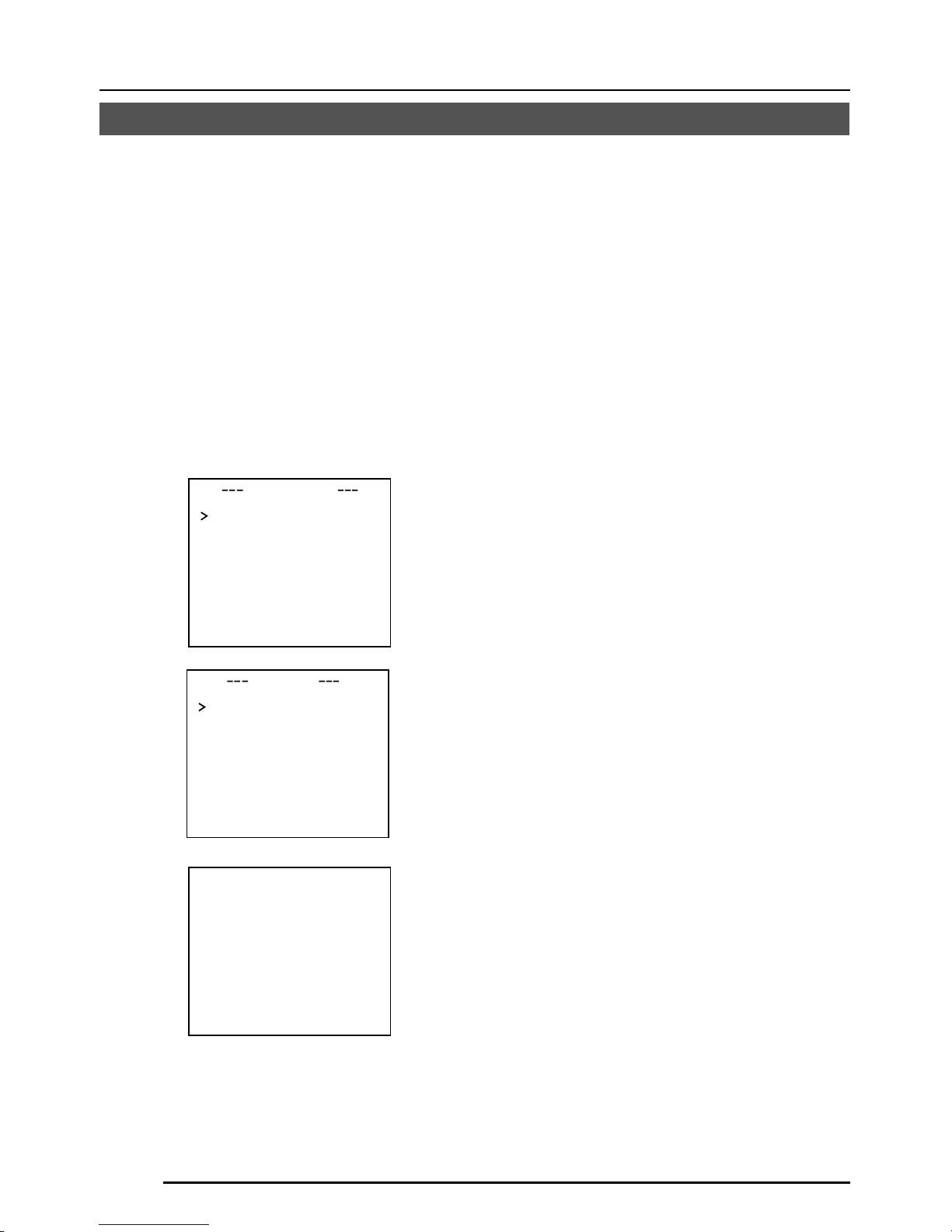
G-36
MENÜEINSTELLUNG
Weißpunktausgleich
CCD-Elemente haben die allgemeine Eigenschaft, dass weiße Punkte auf dem Bildschirm
erscheinen, wenn das CCD-Element bei höheren Temperaturen oder mit längeren
Verschlusszeiten verwendet wird.
Dieses Gerät hat eine eingebaute Funktion zur Verringerung weißer Punkte.
(Die Anzahl und die Größe der weißen Punkte ändert sich entsprechend der Temperatur, der
Verschlusszeit usw., und außerdem ist die Anzahl der weißen Punkte, für die Kompensation
durchgeführt werden kann, begrenzt.)
Bedienungsmethode
1.
Bringen Sie eine Objektivkappe
o.ä. an.
• Verhüten Sie den Eintritt von Licht zum
CCD-Element.
• Schalten Sie die Stromversorgung der
Kamera ein und warten Sie mindestens
30 Minuten.
2.
Zeigen Sie den Wartungsbildschirm
(MAINTENANCE) an.
• Stellen Sie sicher, dass der Cursor (>)
auf dem Punkt CCD SPOT steht.
3.
Drücken Sie die Taste SET.
• Der Bildschirm CCD SPOT wird angezeigt.
• Wenn Sie Weißpunktausgleich nicht
durchführen wollen, so bewegen Sie
den Cursor (>) zu CANCEL und
drücken Sie die Taste SET.
4.
Bewegen Sie den Cursor (>) zu
EXECUTE.
5.
Drücken Sie die Taste SET.
• Weißpunktausgleich wird durchgeführt.
(Während des Betriebs wird “SPOT
SCAN OPERATION” angezeigt.)
6.
Bestätigen Sie die Anzeige.
• Wenn Weißpunktausgleich korrekt
durchgeführt worden ist, wird „SPOT
SCAN OK“ etwa 5 Sekunden lang
angezeigt, und dann erfolgt Rückkehr
zum Bildschirm CCD SPOT.
•
Wenn “SPOT SCAN ERROR: HIGHLIGHT”
angezeigt wird, so stellen Sie sicher, dass
kein Licht zum CCD-Element eintritt.
7.
Drücken Sie die Menütaste
(MENU).
• Rückkehr zum Menübildschirm (MENU)
wird durchgeführt.
INMA T ENA NC E
CC SPOT ..D
SP T SCAN OKO
DCC SPOT
CA ELNC
EX C TEUE
heat up 30min in advance
need Lens–cap to execute
Page 77

G-37
SS412174H-002
TUV
Rheinland
Product Safety
..
geprufte
Sicherheit
..
-NE PAS OUVRIR.
RISQUE DE CHOC ELECTRIQUE
-DO NOT OPEN.
SHOCK HAZARD
SC46171H-001
WARNING:
AVIS:
1/4-20UNC
41
35
70
55
63
42
138
149
39
71
U1-32
54-R
Bildaufnahmeelement: 1/2-Typ IT CCD, 752 (H) × 582 (V)
Synchronisationsmethode: Intern, Leitungsverriegelung, voll Genlock
Abtastfrequenz: (H) 15,625 kHz, (V) 50 Hz
Auflösung: 480 Fernsehzeilen (H)
Videoausgang (VIDEO OUT): Komponentenvideosignal 1 V (p-p), 75 Ω (BNC)
Y/C-Ausgang (Y/C OUT): Y: 1 V (p-p), 75 Ω
C: 0,3 V (p-p), 75 Ω
Videorauschabstand: 50 dB (AGC OFF)
Minimal erforderliche Beleuchtung:
0,6 lx (50 %, F 1,2, AGC 20 dB)
0,3 lx (50 %, F 1,2, AGC 20 dB, LOLUX MODE)
0,3 lx (25 %, F 1,2, AGC 20 dB)
0,15 lx (25 %, F 1,2, AGC 20 dB, LOLUX MODE)
0,019 lx (50 %, F 1,2, AGC 20 dB, SENSE UP ×32)
0,01 lx (50 %, F 1,2, AGC 20 dB, LOLUX MODE, SENSE UP ×32)
Kommunikation: RS-422A oder RS-485 (umschaltbar)
9600 bit/s
Objektivfassung: C-/CS-Fassung
Stromversorgung und Stromverbrauch:
TK-C1480BE
24 V Wechselspannung `, 50 Hz/60 Hz,
12 V Gleichstrom
, 500 mA
TK-C1481BEG
220 V bis 240 V Wechselstrom `, 50 Hz/60 Hz, 75 mA
Umgebungstemperatur: –10 °C bis 50 °C (Betrieb)
0 °C bis 40 °C (empfohlen)
Masse: TK-C1480BE 600 ˝
TK-C1481BEG 835 ˝
Zubehör: 4-stiftiger Stecker ........ 1 Ferritkern ......... 1
Bedienungsanleitung .. 2
Änderungen des Entwurfs und der technischen Daten bleiben jederzeit vorbehalten.
SONSTIGES
Technische Daten
Abmessungen (Einheit: mm)
Page 78

Printed in Japan
LWT0065-001A
is a registered trademark owned by VICTOR COMPANY OF JAPAN, LTD.
is a registered trademark in Japan, the U.S.A., the U.K. and many other countries.
© 2002 VICTOR COMPANY OF JAPAN, LIMITED
®
®
TK-C1480B, TK-C1481B
VICTOR COMPANY OF JAPAN, LIMITED
Page 79

TK-C1480B
TK-C1481B
MANUEL D’INSTRUCTIONS
CAMERA VIDEO COULEUR
Français
BF
LOOK
C
O
L
O
R
VIDEO
C
A
M
E
R
A
DIGITAL
∞
LWT0065-001A
(CD-ROM)
Page 80

F-2
AVERTISSEMENT :
POUR REDUIRE TOUT RISQUE DE
FEU OU DE CHOC ELECTRIQUE,
NE PAS EXPOSER CET APPAREIL
A LA PLUIE NI A L’HUMIDITE._
En raison de changements dans la conception,
les données du mode d’emploi sont sujettes à
modification sans préavis.
Consignes de sécurité
Page 81

F-3
Deutsch
Français
Español
Italiano
Table des matières
Nous vous remercions d’avoir acheté cet appareil.
(Ces instructions s’appliquent au modèle TK-C1480BE et TK-C1481BEG)
Avant de mettre l’appareil en service, veuillez lire attentivement toutes ces instructions
de façon à en obtenir les meilleurs résultats.
INTRODUCTION
Caractéristiques ...................................................................................................................4
Précautions d’utilisation.......................................................................................................5
Commandes, connecteurs et indicateurs ............................................................................6
RACCORDEMENTS/INSTALLATION
Système RM-P2580 ..........................................................................................................10
Procedures ........................................................................................................................12
Montage de l’objectif.......................................................................................................... 13
Installation du tore de ferrite ..............................................................................................14
Raccordements sur le panneau arrière .............................................................................14
Montage de la caméra .......................................................................................................16
Réglage de l’objectif ..........................................................................................................18
Réglage de la mise au point arrière ..................................................................................19
Réglage de commande automatique de la balance des blancs ....................................... 20
REGLAGE DES MENUS
Réglage du menu .............................................................................................................. 21
Déroulement des menus ...................................................................................................22
Ecran SYNC ADJUST ....................................................................................................... 24
Ecran ALC SETTINGS ...................................................................................................... 24
Ecran VIDEO ADJUST ......................................................................................................28
Ecran MODE SELECT ......................................................................................................29
Ecran MOTION DETECT................................................................................................... 30
Ecran COMMUNICATION ................................................................................................. 31
Ecran MAINTENANCE ......................................................................................................31
Ecran FACTORY SETTINGS.............................................................................................31
Ecran BLC EDITTING .......................................................................................................32
Réglage manuel de la balance des blancs ....................................................................... 33
Réglage de CAMERA TITLE ............................................................................................. 34
Réglage de la fonction MOTION DETECT........................................................................ 35
Correction des taches blanches ........................................................................................ 36
AUTRES
Fiche technique .................................................................................................................37
Page 82

F-4
Un DSP de conception nouvelle offre une
plage dynamique étendue (ExDR) et
permet la prise de vue dans les lieux
sombres aussi bien que clairs.
L’adoption d’un capteur CCD avec
fonction SENSE UP (X32) permet
d’obtenir une densité de flux lumineux
minimale du sujet de 0,6 lx (F1,2, 50%,
AGC 20 dB) et de 0,019 lx (à obturateur
lent).
Une fonction de détection de mouvement
détecte les mouvements à l’intérieur de
l’image et émet des signaux d’alarme.
Les prises Y/C et la prise RS-422A/RS-
485 assurent la compatibilité avec
différents systèmes.
Zoom électronique
Le zoom électronique 10x permet un
contrôle avec infiniment plus de détails.
Caractéristiques
Avant d’effectuer un enregistrement
important, bien effectuer un essai
d’enregistrement pour s’assurer que
l’enregistrement fonctionne normalement.
Nous déclinons toute responsabilité
pour les pertes d’enregistrement
résultant d’une impossibilité
d’enregistrement due à une anomalie
de la caméra vidéo, du magnétoscope
ou de la cassette vidéo.
Nous déclinons toute responsabilité
pour les dommages de la caméra
résultant d’une chute due à une
installation incomplète suite au non
respect des instructions d’installation.
Faire attention lors de l’installation de
la caméra.
La fonction de détecteur de mouvement
n’est pas conçue pour empêcher le vol,
le feu, etc. Nous ne saurions être tenus
responsables s’il se produit un accident
entraînant des dommages.
INTRODUCTION
Caractères et symboles utilisés dans ce manuel d’instructions.
PRECAUTION : Remarques d’avertissement concernant une utilisation de l’appareil
MEMO : Références diverses, notamment restrictions des caractéristiques, etc.
: Page ou élément de référence
Page 83

F-5
Deutsch
Français
Español
Italiano
● Pour économiser l’énergie, bien éteindre
le système lorsqu’on ne s’en sert pas.
● La caméra a été conçue pour un usage
intérieur. Si vous l’utilisez à l’extérieur,
prévoyez un boîtier de protection ou
quelque chose de similaire.
● Ne pas installer ni utiliser la caméra dans
les endroits suivants:
• Endroits exposés à la pluie ou à
l’humidité
• Endroits exposés à la vapeur ou aux
fumées grasses, par exemple dans une
cuisine
• Endroits dont la température dépasse la
plage de température de fonctionnement
(–10°C à 50°C)
• Près d’une source de rayonnement, de
rayons X, d’ondes radio ou d’ondes
magnétiques puissantes
• Endroits sujets aux vibrations
• Endroits excessivement sales.
● Si la caméra et les câbles raccordés à la
caméra sont utilisés dans un
environnement dégageant de fortes ondes
magnétiques ou en présence de
magnétisme, par exemple près d’une radio
ou d’un émetteur de télévision, d’un
transformateur de puissance ou d’un
moteur électrique, l’image risque d’être
parasitée et les couleurs d’être affectées.
●
La caméra renferme un circuit AGC. Pour
cette raison, lorsqu’elle fonctionne dans des
conditions d’éclairage faible, sa sensibilité
s’accroît automatiquement et l’image risque
d’être granuleuse. Ceci est normal.
● Si l’on uuue un type d’émetteur-récepteur
engendrant des champs magnétiques
puissants à proximité lorsque l’AGC est en
service, l’image risque d’être affecté par
des battements, etc.
Dans ce cas, éloigner la caméra de plus
de trois mètres de émetteur-récepteur en
question.
● Un battement peut parfois apparaître sur
l’écran si vous augmentez le gain lorsque
le verrouillage de ligne est en service, mais
ce phénomène est dû à la fluctuation de
la fréquence de l’alimentation et n’est donc
pas un mauvais fonctionnement.
Précautions d’utilisation
● Lorsque la caméra fonctionne en mode ATW
(balance des blancs à suivi automatique),
les couleurs des images enregistrées
risquent d’être légèrement différentes des
couleurs réelles en raison du principe de
fonctionnement du circuit de balance des
blancs à suivi automatique. Ceci est normal.
● Si la caméra prend un sujet à forte intensité
(par exemple une lampe), l’image de
l’écran risque d’avoir des lignes verticales
(marbrures) ou d’être floue sur sa
périphérie. Ce phénomène est typique des
capteurs CCD, et il est normal.
● Observer les précautions suivantes lors de
l’entretien de la caméra.
• Ce manuel d’instructions a été préparé
en quatre langues (allemand, français,
espagnol et italien).
Si elle est très sale, nettoyer la section sale
avec un chiffon (ou un chiffon en papier)
trempé dans une solution de détergent naturel.
● L’appareil doit être alimenté sur un courant
CC de 12 V ou sur un courant CA de 24 V.
(TK-C1480BE)
L’alimentation CA de 24 V devra respecter
l’impératif suivant : Alimentation isolée
seulement
TK-C1481BEG Raccorder le cordon
d’alimentation à l’alimentation commerciale
de 230 V.
● Précaution relative au fonctionnement de
l’objectif à diaphragme vidéo
Si le niveau de l’objectif à diaphragme vidéo
est réglé trop bas, cela risque d’engendrer
une anomalie, par exemple une instabilité,
phénomène dans lequel le diaphragme
s’ouvre ou se ferme indépendamment de
la volonté de l’opérateur.
Dans ce cas, commencer par régler le
potentiomètre “LEVEL” de l’objectif sur la
position H (diaphragme ouvert), puis le
régler au niveau optimal.
●
Il peut arriver que la butée du câble du bloc
de connexion se déconnecte. Bien prendre
le temps de vérifier si le câble est raccordé
correctement, et corriger le cas échéant.
● Lors de la prise de vue d’un sujet violemment
éclairé, on observe parfois des ondulations sur
les lignes verticales du sujet. Ce phénomène
est spécifique à l’appareil et il n’est pas le
signe d’un mauvais fonctionnement.
Page 84

F-6
INTRODUCTION
Commandes, connecteurs et indicateurs
1
Monture d’objectif
La monture d’objectif est compatible avec
les objectifs à monture C et les objectifs
à monture CS.
2
Bague de réglage de la mise au point
arrière
Cette bague permet à la fois de régler la
mise au point arrière et de commuter
entre la monture C et la monture CS.
Desserrer la vis BF LOCK
3
en la
tournant dans le sens inverse des aiguilles d’une montre avant de tourner cette
bague, et bien fixer la vis
3
en la
tournant dans le sens des aiguilles d’une
montre après avoir tourné cette bague.
3
Vis de verrouillage de mise au point
arrière [BF LOCK]
Cette vis verrouille le mécanisme de
réglage de la mise au point arrière.
4
Etrier de montage de la caméra
L’étrier a été fixé en usine sur le fond de
la caméra. Il est également possible de
le fixer sur le dessus, en fonction des
circonstances.
Pour remonter l’étrier, utiliser les vis filetée
sur le dessus de la caméra, avec les vis
de verrouillage d’étrier de montage de
caméra
7
.
5
Orifice de vis de montage de la caméra
(1/4 pouce)
Utiliser cet orifice pour monter
la caméra sur un module de
fixation, un module de
mouvement horizontal/vertical,
etc.
(Utiliser une vis de moins de 7 mm.)
6
Orifice de prévention de rotation
Utiliser cet orifice de prévention de rotation
pour empêcher toute chute pendant le
montage de la caméra. Vérifier que la
caméra est solidement fixée.
7
Vis de verrouillage d’étrier de montage
de la caméra (2 : M2,6 × 6 mm)
Bien utiliser une vis de 6 mm de long.
MAX.
7
mm
Page 85

F-7
Deutsch
Français
Español
Italiano
ON
SIMPLEX
ON
LL
SET
AWC
MENU
CAMERA
SETUP
EXT TERM-OFF
INT/GL
DUPLEX
RX TERM-OFF
NOT USED
VIDEO
DC
IRIS
8
Couvercle
Le couvercle s’ouvre lorsqu’on le tire vers
la gauche tout en appuyant dessus.
9
Sélecteur de diaphragme [VIDEO/DC]
Le régler en fonction de l’objectif lorsqu’on
utilise un objectif à commande automatique
de diaphragme.
VIDEO: Cas d’un objectif avec ampli EE
incorporé
DC: Cas d’un objectif sans ampli EE
incorporé
(VIDEO: Réglage usine)
10
Prise de diaphragme [IRIS]
La raccorder à un objectif à commande
automatique de diaphragme.
( Page 13)
11
Touche de menu [MENU]
Quand on appuie sur cette touche, le
menu s’affiche.
( Page 21)
12
Touche de commande de réglage
automatique de la balance des blancs
[SET/AWC]
SET: Appuyer sur cette touche pour
afficher un menu.
( Page 21)
AWC: Si l’on maintient cette touche
enfoncée pendant plus d’une
seconde, la fonction de balance
des blancs automatique par
poussée s’active et la balance des
blancs se règle. Une fois qu’elle
est réglée, la balance des blancs
de bouge plus, même si la
température de couleur change.
Il est également possible
d’effectuer un réglage fin de la
balance des blancs.
( Page 20)
Page 86

F-8
Commandes, connecteurs et indicateurs (suite)
INTRODUCTION
13
Touche haut-et-bas, gauche-et-droite
[
, , , ]
Elle permet de sélectionner les rubriques
sur le menu et de modifier les valeurs.
( Page 21)
14
Commutateur de marche/arrêt de
prise de signal de synchronisation
externe [EXT/TERM-ON/OFF]
Il permet de régler si le signal de
synchronisation envoyé à la prise SYNC
IN du panneau arrière
25
doit être
terminé à 75 Ω ou non.
ON: Terminaison à 75 Ω.
OFF: Pas de terminaison à 75 Ω.
(ON : Réglage usine)
15
Sélecteur de système de synchronisation
[INT/GL, LL]
Il permet de régler le système de
synchronisation de la caméra.
INT/GL:
Pour la synchronisation interne (INT) ou
la synchronisation externe (GL).
LL (verrouillage de ligne):
La synchronisation verticale de la caméra
se règle en fonction de la fréquence de
l’alimentation CA 24 V.
Lors de la commutation entre plusieurs
caméras avec un module de commutation,
sélectionner ce mode et régler la phase
verticale pour réduire les perturbations de
synchronisation du moniteur qui se
produisent lors de la commutation des
caméras. (Cette fonction ne peut être
utilisée dans les régions ayant une
fréquence d’alimentation de 60 Hz)
16
Sélecteur de système de transmission
[DUPLEX, SIMPLEX]
Si le réglage a été modifié, il faudra
impérativement remettre l’appareil sous
tension.
DUPLEX:
Régler sur cette position lorsque la
transmission entre la caméra et la
télécommande s’effectue suivant un
système bidirectionnel (deux voies).
SIMPLEX:
Régler sur cette position pour lorsque la
transmission entre la caméra et la
télécommande s’effectue suivant un
système unidirectionnel (une voie).
(DUPLEX : Réglage usine)
17
Commutateur de marche/arrêt de
prise de signal RX [RX.TERM-ON/OFF]
Il permet de régler si le signal entre RX+
et RX– du panneau arrière
20
doit être
terminé à une valeur de résistance de
110 Ω ou non.
ON: Terminaison
OFF: Pas de terminaison
Si le système qui intègre la caméra est
un système M.DROP (Multi-drop, RS-
485), seule la caméra montée à la prise
du câble de signal de commande se règle
sur “ON”, et l’autre caméra se règle sur
“OFF”. Avec un système M.DROP, il
faudra régler le code d’identification (ID)
de machine. ( Page 31)
Si le système qui intègre la caméra est
un système P TO P (Point à point, RS422A), régler toutes les caméras sur
“ON”.
La rubrique STYLE de l’écran
COMMUNICATION permet de régler
M.DROP ou P TO P. ( Page 31)
(ON : Réglage usine)
18
Pas utilisé
Ne sert pas. Ne pas l’utiliser.
Page 87

F-9
Deutsch
Français
Español
Italiano
19
Prises d’entrée d’alimentation [DC 12V, AC 24V]
(TK-C1480BE)
Pour acheminer l’alimentation CC 12 V
ou CA 24 V.
20
Prises de raccordement de signal de
commande [TX+A, T X–B, RX+C, RX–D]
Ce sont les prises d’entrée de signaux dont les
caractéristiques électriques sont conformes à
la norme EIA/TIA RS-422A ou RS-485.
17 Commutateur RX. TERM
21
Prises de sortie auxiliaires [AUX, GND]
S’il se produit un changement dans la section
réglée à l’écran MOTION DETECTING, ces
prises envoient les signaux. ( Page 30)
[
Collecteur ouvert, signal bas. Tension
maximum 30V, courant 30 mA]
22
Connecteur de sortie Y/C [Y/C OUT]
Ce connecteur à 4 broches envoie les
signaux de luminance et de chrominance.
• Configuration des broches du connecteur
Y/C OUT
23
Connecteur de sortie de signal vidéo
[VIDEO OUT]
Ce connecteur BNC envoie un signal
vidéo composite. Le raccorder au
connecteur d’entrée vidéo d’un moniteur
vidéo, module de commutation, etc.
24
Voyant d’alimentation [POWER]
Il s’allume lorsque la caméra est
alimentée.
25
Connecteur d’entrée de signal de
synchronisation [SYNC IN]
Ce connecteur BNC accepte l’entrée
d’un signal de synchronisation externe,
par exemple un signal vidéo composite
(VBS) ou un signal de noir codé (BB).
Si un signal de synchronisation est envoyé
à ce connecteur, le fonctionnement de la
caméra se synchronise immédiatement sur
le signal de synchronisation externe.
Pour terminer ce connecteur à 75 Ω,
tourner le commutateur EXT.TERM
14
sur ON.
26
Cordon d’alimentation (TK-C1481BEG)
Le raccorder à l’alimentation commerciale
de 230 V.
No. de broche
Signal
1 GND
2 GND
3 Luminance (Y)
4 Chrominance (C)
4
2
3
1
TK-C1480BE
TK-C1481BEG
DC12V
AC24V
Y/C OUT
SYNC IN
POWER
VIDEO OUT
SEE INSTRUCTION
MANUAL
+
-
12
CLASS 2 ONLY(U TYPE)
ISOLATED POWER ONLY
(E TYPE)
TX+TX
-
RX+RX
-
AUX
GND
A
B
CD
⁄
)
(
fi
›
¤
‹
Y/C OUT
SYNC IN
POWER
VIDEO OUT
SEE INSTRUCTION
MANUAL
TX+TX
-
RX+RX
-
AUX
GND
A
B
CD
fl
Page 88

F-10
REC
PLAY
FFREW
REVERSE
PAUSE/
STILL
REC
CHECK
STOP/EJECT
COUNT/
CLOCK
TIME
MODE
TIMER
REC
AL/PL
RESET
MENU
VIDEO CASSETTE RECORDER
SHIFT/TRACKING
SET/V.LOCK
RESET
/CANCEL
OPERATE
SR-L910
OPE. LOCK
1
TO CAMERA
TO CAMERA
DATA I / O
DATA I / O
RX
RX
+
RX
RX
TX
TX
+
TX
TX
-
COM
COM
1 2 3 4 5 6 7 8
COM
COM
9/1
9/1
10/2
10/2
11/3
11/3
12/4
12/4
13/5
13/5
14/6
14/6
15/7
15/7
16/8
16/8
COM
COM
COM
COM
COM
COM
CAMERA
CAMERA
SW
SW
UNIT
UNIT
ALARM
ALARM
AUTO
AUTO
431 2 875 6
2 3 4 5 6 7
8
1
MONITOR
MONITOR
OUTPUT
MONITOR
MONITOR
SERIAL-2
SERIAL-2
SERIAL-1
SERIAL-1
VIDEO INPUT
VIDEO INPUT
VIDEO OUTPUT
OUTPUT
2
1
ON
2 3 4 5 6 7
8
POWER
OFF
ON
AC INPUT
ALC
LEVEL
Av Pk
L H
ALC
LEVEL
Av Pk
L H
ALC
LEVEL
Av Pk
L H
•••••
CAMERA
Télécommande
RM-P2580
Magnétoscope à
temps échelonné
Moniteur
CAL SW
OUT
VIDEO IN
COM
VERS LA
CAMERA
SORTIE DE
MONITEUR 2
SORTIE DE
MONITEUR 1
RACCORDEMENTS/INSTALLATION
Système RM-P2580
Système avec 8 caméras maximum
Caméra
TK-C1480B
Caméra 1
Caméra 2
Caméra 8
Câble de signal de commande
Câble de signal vidéo
Cordon
d’alimentation
Voici un exemple de raccordement du TK-C1480BE.
Lorsque la commande est exercée via un système autre que la télécommande RM-P2580, effectuer les
réglages avec les commutateurs et les écrans de menu en fonction du système utilisé. ( Page 12)
PROT OOLDUPLEXID-05C :
ID MACHINE : 1
(écran de menu)
RX TERM : OFF
(commutateur)
ID MACHINE : 2
(écran de menu)
RX TERM : OFF
(commutateur)
ID MACHINE : 8
(écran de menu)
RX TERM : ON
(commutateur)
MEMO
•
Lorsqu’on pilote le système avec la télécommande RM-P2580, il sera possible de raccorder plusieurs caméras
(8 maximum) et de les piloter avec un seul câble de signal de commande. Par conséquent, un réglage incorrect
des commutateurs sur une seule caméra provoquera un fonctionnement erroné de l’ensemble du système.
•
Vérifier le réglage des commutateurs à l’écran, de la façon suivante.
q Vérifier que l’image envoyée par la caméra à vérifier
s’affiche sur le moniteur.
w Couper (OFF) puis enclencher (ON) l’alimentation CA
24 V pour la caméra à vérifier.
e La caméra commence à fonctionner et des caractères
comme ceux indiqués sur le schéma de droite
s’affichent à l’écran du moniteur.
r Vérifier que “DUPLEX” et “ID-□□” sont affichés et que
le code ID est correct (le code ID doit être le même
que celui de la prise VIDEO INPUT à laquelle la caméra
est raccordée, sur le panneau arrière de la
télécommande RM-P2580).
t Si le code ID est incorrect, rerégler le code ID de la
caméra.
CA 24 V
ou
CC 12 V
SW
Moniteur
Ecran MONITOR
(Exemple montrant le code ID de caméra “05”
“DUPLEX” doit
s’afficher.
Le code affiché à la
section □□ de ID-□□
doit être correct.
CA 24 V
ou
CC 12 V
CA 24 V
ou
CC 12 V
Caméra
TK-C1480B
Caméra
TK-C1480B
Page 89

F-11
Deutsch
Français
Español
Italiano
CAMERA
SETUP
SET
MENU
EXT TERM-OFF
INT/GL
DUPLEX
RX TERM-OFF
NOT USED
ON
LL
SIMPLEX
ON
EXT TERM-OFF
INT/GL
DUPLEX
RX TERM-OFF
NOT USED
ON
LL
SIMPLEX
ON
VIDEO
DC
IRIS
AWC
A RX
+
B RX
C TX
+
D TX
TX+ A
TX
B
RX
+
C
RX
D
TX
+
A
TX B
RX
+
C
RX
D
RM-P2580
Caméra 2
Prises de raccordement
de signal de commande
Raccorder:
Caméra TX+ à télécommande RM-P2580 RX+
Caméra TX– à télécommande RM-P2580 RX–
Caméra RX+ à télécommande RM-P2580 TX+
Caméra RX– à télécommande RM-P2580 TX–
Les repères A B C et D indiqués sur les
prises de la caméra et les prises de la
télécommande RM-P2580 facilitent les
raccordements. Raccorder ensemble les
prises ayant des repères identiques.
Raccordement du câble de signal de commande
(Pour le raccordement, utiliser un câble à paire torsadée. Page 15)
Caméra 1
Prises de raccordement
de signal de commande
Réglage des commutateurs ( Page 8)
Sélectionner la méthode de synchronisation de l’image de la
caméra.
Régler le commutateur de toutes les caméras sur LL
(verrouillage de ligne) et faire correspondre avec la V.PHASE.
( Page 24)
Régler sur DUPLEX.
* Si le réglage a été modifié, il faudra impérativement
remettre l’appareil sous tension.
Régler sur ON (marche de terminaison du signal) uniquement
sur la caméra placée à l’extrémité du câble de signal de
commande.
Régler sur OFF sur toutes les autres caméras.
Réglage de l’écran MENU ( Page 31)
* Si le réglage a été modifié, quitter une fois l’écran de menu, puis remettre l’appareil sous tension.
Commutateurs de réglage du code CD de
machine
Régler en fonction du numéro de la prise
VIDEO INPUT de la RM-P2580 pour chaque
caméra.
Pour les raccordements:
● Mettre tous les appareils à raccorder hors tension avant d’effectuer les raccordements.
● Lire attentivement le manuel d’instructions de chaque appareil avant d’effectuer les
raccordements.
● Pour connaître le type et la longueur des câbles, lire attentivement la section “Raccordements”,
à la page 14.
● Le câble de signal de commande ne peut pas être utilisé pour le raccordement en boucle.
Régler sur M.DROP.
Régler sur M.DROP si l’on utilise la
télécommande RM-P2580. Si la commande est
exercée via une autre machine, veiller à ce
qu’elle corresponde au système de
communication utilisé.
MMCO UNICAT ION
S T L E M. DROPY
MA H NE DII 1C
Page 90

F-12
RACCORDEMENTS/INSTALLATION
SET
MENU
CAMERA
SETUP
EXT TERM-OFF
INT/GL
DUPLEX
RX TERM-OFF
IOT USED
ON
LL
SIMPLEX
ON
VIDEO
DC
ALC
LEVEL
Av Pk
L H
Effectuer les raccordements/installation en procédant comme indiqué ci-dessous.
Mettre tous les appareils à raccorder hors tension avant d’effectuer les raccordements.
4.
Réglage des commutateurs
( Page 11)
6.
Réglage de la mise au point arrière
( Page 19)
5.
Réglage de l’objectif
( Page 18)
7.
Réglage de commande
automatique de la balance
des blancs
( Page 20)
3.
Montage de la caméra
( Page 16)
Vers les systèmes de
commande, par exemple la
télécommande RM-P2580
Vers les prises d’alarmes,
par exemple les
commutateurs
Moniteur
2.
Raccordements
( Page 14)
Alimentation
CC 12 V ou CA 24 V
Procedures
Générateur de
signal de synchronisation
de verrouilleur de
synchronisation
1.
Montage de l’objectif
( Page 13)
Voici un exemple de raccordement du TK-C1480BE.
TK-C1481BEG ( Page 14)
DC12V
AC24V
CLASS 2 ONLY(U TYPE)
ISOLATED POWER ONLY
(E TYPE)
TX+TX
-
RX+RX
-
AUX
Y/C OUT
SYNC IN
POWER
VIDEO OUT
GND
ABCD
SEE INSTRUCTION
MANUAL
1
+
-
2
Page 91
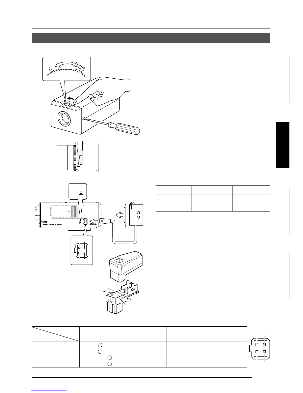
F-13
Deutsch
Français
Español
Italiano
Montage de l’objectif
VIDEO
DC
IRIS
VIDEO
DC
3
42
1
Monter l’objectif en procédant comme indiqué ci-dessous.
Indicateurs des 4 broches
1.
Avant de monter l’objectif, vérifier si c’est
un objectif à monture C ou à monture CS.
Pour changer de méthode de monture
d’objectif, desserrer la vis de verrouillage
de la mise au point arrière (M2,6) à l’aide
d’un tournevis à tête Phillips, tourner la
bague de réglage de la mise au point
arrière avec les doigts ou avec un tournevis,
et changer de méthode de montage.
La dimension (b) de l’objectif qui est
représentée sur le schéma doit être
comme indiqué dans le tableau cidessous. Si (b) dépasse la valeur du
tableau, cela risque d’endommager
l’intérieur de la caméra ou de rendre le
montage impossible ; ne jamais utiliser
des objectifs de ce genre. Ne pas fixer
d’objectif à monture C lorsqu’on utilise
une monture CS.
Le repère F représente un foyer.
2.
Monter l’objectif sur la caméra en
tournant l’objectif dans le sens des aiguilles d’une montre. Régler sa position.
3.
Si l’on utilise un objectif à diaphragme
automatique avec amplificateur EE, tourner
le commutateur vers le côté “VIDEO”. Si
l’objectif n’a pas d’amplificateur EE, tourner
le commutateur vers le côté “DC”.
4.
Si l’objectif possède un mécanisme de
diaphragme automatique, raccorder le
câble de l’objectif après avoir vérifier la
disposition des broches.
Si le câble de l’objectif posssède une
fiche d’un type différent, utiliser la fiche
à 4 broches fournie.
Objectif
Tirage optique (c)
Dimension (b)
Objectif à monture C
17,526 mm
10 mm ou moins
Objectif à monture CS
12,5 mm
5,5 mm ou moins
1
3
4
2
B
F
L
O
C
K
1
3
2
4
(b)
(c)
F
Objectif DC IRIS VIDEO IRIS
No. de broche
(ne renferme pas d’amplificateur EE)
(renferme un amplificateur EE)
1 Frein
–
9 V [max. 50 mA]
2 Frein
+
NC
3 Conduite
+
VIDEO
4 Conduite
–
TERRE
3.
2.
4.
Page 92
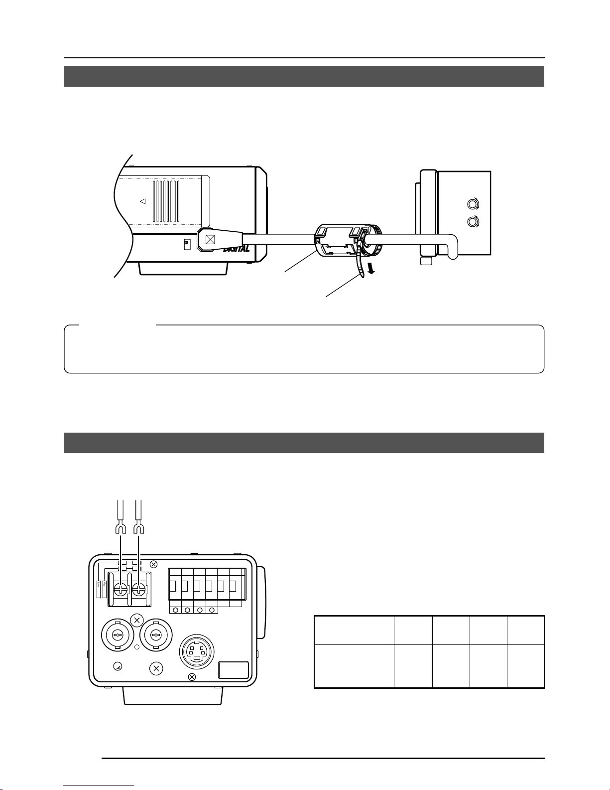
F-14
RACCORDEMENTS/INSTALLATION
Installation du tore de ferrite
Pour conserver la compatibilité électromagnétique, utiliser les tores de ferrite fournis lors du
raccordement de l’objectif.
Remarques:
Installer les tores de ferrite à 50 mm maximum des connecteurs latéraux de la caméra.
(Fixer le tore de ferrite avec le collier de serrage fourni.)
Objectif à diaphragme vidéo
(ou objectif à diaphragmegalvanométrique)
Tore de ferrite
Raccorder l’alimentation CC 12 V ou CA 24
V aux prises DC 12V/AC 24V. Pour éviter
toute erreur de raccordement, il est
recommandé d’utiliser des plaques à cosse
terminale pour les raccordements.
Le tableau suivant donne les distances et les
câbles de raccordement, à condition toutefois
que l’on utilise des câbles VVF (câbles à gaine
de vinyle isolée au vinyle) à 2 conducteurs.
Rallonge maximale
(référence)
Diamètre de
conducteur
100 m 260 m 410 m 500 m
Dia. Dia. Dia. Dia.
1,0 mm 1,6 mm 2,0 mm 2,6 mm
et plus et plus et plus et plus
Raccordements sur le panneau arrière
Alimentation
TK-C1480BE (CC 12V ou CA 24 V)
Serre-fils
DC12V
AC24V
CLASS 2 ONLY(U TYPE)
ISOLATED POWER ONLY
(E TYPE)
TX+TX
-
RX+RX
-
AUX
Y/C OUT
SYNC IN
POWER
VIDEO OUT
GND
A
B
CD
SEE INSTRUCTION
MANUAL
1
+
-
2
VIDEO
DC
IRIS
ALC
LEVEL
Av Pk
L H
Page 93

F-15
Deutsch
Français
Español
Italiano
MEMO
• Si l’on utilise des câbles minces (c.-à-d. à haute résistance), il se produira une baisse de
tension importante lorsque l’appareil atteindra sa consommation maximale. Utiliser un
câble épais de façon à maintenir la baisse de tension sur le côté caméra en-dessous de
10%, ou rapprocher l’alimentation de la caméra. S’il se produit des baisses de tension
pendant le fonctionnement, les performances seront instables.
• Fixer les conducteurs de câble de façon qu’ils n’entrent pas en contact avec les fils de
prévention de chute.
• Ne pas alimenter l’appareil sur une alimentation CC de 12 V et une alimentation CA de 24 V
en même temps.
• Si l’on utilise une alimentation CC de 12 V, s’assurer que les polarités des câbles sont correctes.
• L’alimentation CA de 24 V devra respecter l’impératif suivant :
TK-C1480BE Alimentation isolée seulement
TK-C1481BEG (AC 230 V)
Raccordez le câble d’alimentation à une prise
secteur de 230 V.
Attention:
Lorsque vous utilisez la caméra, installez
l’appareil à proximité de la prise secteur de
façon à pouvoir débrancher le câble facilement.
Vers les systèmes de
commande, par exemple la
télécommande RM-P2580
Alimentation CC
12 V ou CA 24 V
Générateur de
signal de
synchronisation
de verrouilleur de
synchronisation
TK-C1480BE
Câbles de signal de commande
On ne raccordera ces câbles que si la caméra
doit être pilotée avec des signaux RS-442A
ou RS-485. Il est recommandé d’utiliser des
câbles à paire torsadée à 4 conducteurs de
calibre 0,65. Avec ces câbles, la distance de
rallonge maximale est de 1.200 m.
Raccordement du verrouilleur de synchronisation
Avec certains systèmes, lorsque le signal de
synchronisation externe est un signal vidéo
composite ou un signal de noir codé, le
verrouillage de synchronisation par application
d’une entrée de synchronisation externe
nécessitera un réglage de la phase horizontale
(H PHASE) et/ou de la phase couleur (SC
COARSE).
MEMO
• Le verrouillage de synchronisation n’est pas
possible avec un signal renfermant trop de
sautillements, par exemple le signal de lecture
d’un magnétoscope ou d’un vidéodisque.
• Pour les détails, consulter un revendeur JVC agréé.
Raccorder à l’autre
côté en paires,
comme ceci.
Raccorder à l’autre
côté en paires,
comme ceci.
A
B
TX+
TX
-
C
D
RX+
RX
-
Y/C OUT
SYNC IN
POWER
VIDEO OUT
SEE INSTRUCTION
MANUAL
DC12V
AC24V
CLASS 2 ONLY(U TYPE)
ISOLATED POWER ONLY
(E TYPE)
TX+TX
-
RX+RX
-
AUX
Y/C OUT
SYNC IN
POWER
VIDEO OUT
GND
ABCD
SEE INSTRUCTION
MANUAL
1
+
-
2
Page 94

F-16
RACCORDEMENTS/INSTALLATION
DC12V
AC24V
CLASS 2 ONLY(U TYPE)
ISOLATED POWER ONLY
(E TYPE)
T
X
+
T
X
-
R
X
+
R
X
-
A
U
X
Y/C OUT
SYNC IN
POWER
VIDEO OUT
G
N
D
A
B
CD
S
E
E
IN
S
T
-
R
U
C
T
IO
N
M
A
N
U
A
L
+
-
1
2
2mm
6mm
M3 x 6mm
MAX.
7
mm
Montage de la caméra
Vis de montage
de caméra
Etrier de montage
de caméra
Orifice de prévention
de rotation
Pour monter la caméra sur un module de
fixation, un module de mouvement horizontal/
vertical, utiliser l’orifice pour vis de montage
de caméra.
Par ailleurs, utiliser l’orifice de prévention de
chute pour empêcher que la caméra ne
tombe et la fixer solidement.
Prendre des précautions spéciales pour le
montage de la caméra sur un mur ou un
plafond. Nous déclinons toute responsabilité
pour les dommages résultant d’une
installation incorrecte.
Prévention des chutes
• Faire extrêmement attention lorsqu’on
installe l’appareil sur un mur ou sur un
plafond. Ne pas effectuer ce travail
d’installation soi-même. Confier ce travail
à un professionnel, car la chute de
l’appareil risque de provoquer des
blessures et des accidents.
•
Lorsqu’on installe l’appareil sur un module
de fixation, un module de mouvement
horizontal/vertical, etc., bien l’installer
solidement en utilisant l’orifice de prévention
de rotation pour l’empêcher de tomber.
•
Pour empêcher toute chute de l’appareil,
raccorder l’appareil à une section
suffisamment résistante (dalle de plafond
ou cannelure) en utilisant un fil de
prévention des chutes, par exemple une
chaîne métallique. Pour l’installer, utiliser
la vis noire du panneau arrière de l’appareil.
Faire extrêmement attention à la longueur
du fil métallique également.
• Vis spécifiée (M3 × 6 mm)
Ne jamais utiliser de vis d’une longueur
supérieure à la longueur spécifiée car cela
pourrait endommager l’intérieur de
l’appareil.
PRECAUTION:
Utiliser une vis d’une
longueur inférieure à 7
mm par rapport à la
surface de montage de la
caméra.
Ce schéma montre un exemple d’installation
du TK-C1480BE.
Avec le TK-C1481BEG, bien prévoir également
un fil de prévention des chutes.
Page 95

F-17
Deutsch
Français
Español
Italiano
VIDEO
DC
IRIS
VIDEO
DC
IRIS
Etrier de montage
de caméra
Vis de fixation
Installation de la caméra
• Montage sur le fond
A l’origine, la caméra a été conçue en vue
d’un montage sur le fond, comme indiqué
en q. L’orifice est de la taille d’une vis à
tête cylindrique photographique standard
(UNC 1/4-20). Exemple avec le module
de fixation ou le module de mouvement
horizontal/vertical.
• Montage sur le dessus
Retirer l’ETRIER DE MONTAGE DE
CAMERA du fond de la caméra comme
indiqué en w . Fixer l’ETRIER DE
MONTAGE DE CAMERA sur le dessus,
puis monter la caméra sur le module de
fixation comme indiqué en e. Bien utiliser
les 2 vis d’origine pour monter l’ETRIER
DE MONTAGE DE CAMERA. Bien utiliser
une vis de fixation de 6 mm de long pour
le socle de montage de la caméra.
(La caméra s’utilise à l’intérieur et dans
les conditions similaires.)
q
w
e
Page 96

F-18
RACCORDEMENTS/INSTALLATION
Réglage de l’objectif
ALC
LEVEL
Av Pk
L H
Raccorder la caméra en fonction de la méthode de raccordement, la mettre sous tension,
afficher une image sur le moniteur et vérifier l’image. La caméra a été réglée en usine sur la
position optimale, mais il faudra peut-être la rerégler en fonction des conditions du sujet ou de
la combinaison des objectifs. Si l’image ne semble pas naturelle, régler la caméra comme suit
: (Lire également le manuel d’instructions de l’objectif.)
• Réglage de LEVEL
Ecran du moniteur
Sens de rotation de LEVEL
Trop clair Sens inverse des aiguilles
d’une montre (vers L)
Trop sombre Sens des aiguilles d’une
montre (vers H)
MEMO
• Si le niveau de réglage de LEVEL est
tourné trop loin vers L, la sensibilité
augmentera sous l’effet de la fonction AGC
de la caméra et l’image semblera
granuleuse.
• Si le niveau de l’objectif à diaphragme vidéo
est réglé trop bas, cela risque d’engendrer
une anomalie, par exemple une instabilité,
phénomène dans lequel le diaphragme
s’ouvre ou se ferme indépendamment de
la volonté de l’opérateur.
Dans ce cas, commencer par régler le
potentiomètre LEVEL de l’objectif sur la
position H (diaphragme ouvert), puis le
régler au niveau optimal.
Réglage de LEVEL
Réglage de ALC
(Ne fonctionne pas.)
MEMO
Notez que l’objectif ne peut pas effectuer les
réglages ALC. Effectuez les réglages ALC à
l’aide de la rubrique AVERAGE: PEAK sur le
menu.
( Page 24)
Page 97

F-19
Deutsch
Français
Español
Italiano
Réglage de la mise au point arrière
• Avec un objectif à focale fixe
Si l’on ne parvient pas à obtenir la mise au
point en tournant la bague de mise au point
de l’objectif, régler la mise au point arrière
comme suit.
1.
Desserrer la vis de verrouillage de mise
au point arrière en la tournant dans le
sens inverse des aiguilles d’une montre
(
) avec un tournevis.
2.
Prendre un sujet de près.
3.
Tourner la bague de mise au point de
l’objectif sur ⬁.
4.
Tourner la bague de réglage de la mise
au point arrière de façon que le sujet
soit le plus net possible.
5.
Serrer la vis de verrouillage de mise au
point arrière en la tournant dans le sens
des aiguilles d’une montre (
) .
• Avec un objectif zoom
Si l’image est floue lors d’une prise de vue
au zoom (téléobjectif ou grand-angle), régler
la caméra comme suit:
1.
Desserrer la vis de verrouillage de mise
au point arrière en la tournant dans le
sens inverse des aiguilles d’une montre
(
) avec un tournevis.
2.
Prendre une scène relativement sombre avec des lignes fines.
3.
Régler l’objectif à la position de
téléobjectif maximale et régler la mise
au point de l’objectif.
4.
Régler l’objectif à la position de grandangle maximale et tourner la bague de
mise au point arrière de façon à régler
la mise au point.
(Recommencer les opérations
3
et
4
deux ou trois fois de suite.)
5.
Serrer la vis de verrouillage de mise au
point arrière en la tournant dans le sens
des aiguilles d’une montre (
) .
Réglage de la mise au point arrière
Il faudra rerégler la mise au point arrière si l’on change de méthode de monture d’objectif ou
qu’on utilise un objectif différent. Au besoin, effectuer le réglage comme suit:
MEMO
• LENS FOCUS ADJUSTMENT MODE
Au moment du réglage de la mise au point,
appuyer sur la touche
du panneau
latéral de l’appareil pendant au moins une
seconde pour ouvrir le diaphragme et
faciliter la mise au point. A ce moment,
“LENS FOCUS ADJUSTMENT MODE”
s’affiche sur l’écran du moniteur.
Quand le réglage est terminé, appuyer sur
l’une des touches
pour annuler
le mode de réglage de la mise au point.
• Si le sujet est trop brillant, l’utilisation d’un
filtre ND permettra d’obtenir une mise au
point arrière plus nette. (Le filtre ND réduit
la quantité de lumière incidente qui frappe
l’objectif de façon égale sur toute la plage
de longueur d’onde.)
Vis de fixation de la mise
au point arrière (M2,6)
Bague de réglage de la
mise au point arrière
Bague de mise au
point de l’objectif
B
F
L
O
C
K
Serrer
Desserrer
Page 98

F-20
Réglage de commande automatique de la balance des blancs
1.
Placer un objet blanc soumis aux
mêmes conditions d’éclairage que le
sujet devant la caméra et effectuer un
zoom avant de façon que l’objet blanc
remplisse tout l’écran.
2.
Lorsqu’on appuie sur la touche AWC
pendant environ une seconde, la balance des blancs se règle pour le sujet
en cours d’enregistrement.
3.
Pendant que le réglage automatique de
la balance des blancs s’effectue, “AWC
OPERATION” s’affiche (pendant environ
0,5 seconde). Quand la balance des
blancs est correcte, “AWC OK” s’affiche.
4.
Affichage des messages d’erreur
● NG: OBJECT
S’affiche lorsqu’il n’y a pas assez de
blanc sur le sujet ou que la température
de couleur ne convient pas.
Rerégler la balance des blancs en
prenant un objet blanc qui remplit tout
l’écran.
● ERROR: LOW LIGHT
S’affiche lorsque l’éclairage est
insuffisant. Augmenter l’éclairage,
puis rerégler la balance des blancs.
● ERROR: HIGH LIGHT
S’affiche lorsque l’éclairage est trop
brillant. Diminuer l’éclairage, puis
rerégler la balance des blancs.
CAMERA
SETUP
SET
MENU
EXT TERM-OFF
INT/GL
DUPLEX
RX TERM-OFF
NOT USED
ON
LL
SIMPLEX
ON
VIDEO
DC
IRIS
AWC
Touche AWC
AWC OK
Affichage du résultat
AWC OPERATION
Pendant le fonctionnement
Chaque source lumineuse possède sa propre température de couleur. Lorsque la source
d’éclairage principale qui éclaire le sujet change, il faut donc rerégler la balance des blancs
en appuyant sur la touche AWC.
AWC NG : OBJECT
Erreur du sujet
AWC ERROR : LOW LIGHT
Faible éclairage
AWC ERROR : HIGH LIGHT
Eclairage excessif
RACCORDEMENTS/INSTALLATION
Page 99

F-21
REGLAGE DES MENUS
Réglage du menu
CAMERA
SETUP
SET
MENU
EXT TERM-OFF
INT/GL
DUPLEX
RX TERM-OFF
NOT USED
CAMERA
SETUP
SET
MENU
ON
LL
SIMPLEX
ON
VIDEO
DC
IRIS
AWC
1.
Appuyer sur la touche MENU.
L’écran MENU s’affiche.
2.
Amener le curseur (>) sur le
sous-menu voulu à l’aide de la
touche
, .
3.
Appuyer sur la touche SET.
Le sous-menu sélectionné s’affiche.
4.
Utiliser la touche , pour
amener le curseur (>) sur la
rubrique voulue.
5.
Modifier le paramètre à l’aide de
la touche
, .
La modification du paramètre est
signalée par un repère de modification
(*).
Si l’on souhaite modifier le paramètre
d’une autre rubrique, recommencer les
opérations 2. à 5. ci-dessus.
6.
Appuyer sur la touche MENU.
L’écran revient à l’écran précédent
(écran MENU).
7.
Appuyer sur la touche MENU.
L’écran revient à l’écran normal (le menu
disparaît).
* Si l’on effectue le réglage avec la
télécommande RM-P2580, utiliser la
manette au lieu de la touche
.
Touche MENU
Touche SET
MENU
SYNC ADJUST
VIDEO ADJUST
MOD E ESLECT
ALC SETT I NGS
COMMUN I CAT ION
MA IN TEN NACE
MOT I ON
D
E
TECT
..
FACTORY SETTI NGS ..
..
..
..
..
..
..
LACSETTINGS
IIRSLEVEL NORMAL
AEVRAEG:PEAK 82:
ACGMODE
MODE
2dB0
SUTHTERExDR/
NRMALO
LUX
LO O FF
PIORRITY –––
BCLOFF
SNSEEUP OFF
LACSETTINGS
AEVRAEG:PEAK 82:
ACGMODE
2dB0
SUTHTERExDR/
NRMALO
I∗IRS LEVEL -5
OFF
PIORRITY –––
BCLOFF
SNSEEUP OFF
MODE
LUX
LO
LACSETTINGS
IIRSLEVEL NORMAL
AEVRAEG:PEAK 82:
ACGMODE
MODE
2dB0
SUTHTERExDR/
NRMALO
LUX
LO O FF
PIORRITY –––
BCLOFF
SNSEEUP OFF
Page 100

F-22
REGLAGE DES MENUS
Déroulement des menus
Page 24
Page 28
Page 30
Page 33
Page 35
Page 36
Page 36
MENU
SYNC ADJUST
VIDEO ADJUST
MOD E ESLECT
ALC SET T I NGS
COMMUN I CAT ION
MA I N TE N NACE
MOT I ON
D
E
TECT
SYNC DAJUST
VPHASE 0
HPHASE 0
SC ECOARS 0
SC F INE 1 28
DEVI O ADJUST
WH TE BA L E AT WNC
A
I
CO OUR LE NORMALEL
V
L
EN ANCE LE NORMALEL
V
H
PEESTAL LE NORMALEL
V
D
AUOBLAC K OFFTL
C
T
TIMO O N DE TECT
MO E OFFD
LE EL NORMALV
AR A EDIE
ALRMTI EM10sA
DEONSTRATIN
O
M
WH I T E BALANCE CONTROL
AWC SE T . .
RB
::
MG
::
g
INMA TE NANCE
CC SP OT. .D
DCC SPOT
CA ELNC
E
heat up 30min in advance
need Lens–cap to exe cu te
XCTEUE
.
.
..
FACTORY SETT INGS..
..
..
..
..
..
..
T..
 Loading...