

Page 1

COLOUR VIDEO CAMERA
TK-C1460
LOOK
BF
DIGITAL
For Customer Use:
Enter below the Serial No. which is
located on the body. Retain this
information for future reference.
Model No. TK-C1460
Serial No.
INSTRUCTIONS
ERA
CAM
VIDEO
R
O
L
O
C
SC961012H-001
(CD-ROM)
E-1
Page 2

IMPORTANT SAFEGUARDS
1. Read all of these instructions.
2. Save these instructions for later use.
3. All warnings on the product and in the operating instructions should be adhered to.
4. Unplug this appliance system from the wall outlet before cleaning. Do not use liquid cleaners
or aerosol cleaners. Use a damp cloth for cleaning.
5. Do not use attachments not recommended by the appliance manufacturer as they may
cause hazards.
6. Do not use this appliance near water - for example, near a bathtub, washbowl, kitchen
sink, or laundry tub, in a wet basement, or near a swimming pool, etc.
7. Do not place this appliance on an unstable cart, stand, or table. The
appliance may fall, causing serious injury to a child or adult, and
serious damage to the appliance.
Use only with a cart or stand recommended by the manufacturer , or
sold with the appliance. Wall or shelf mounting should follow the
manufacturer’ s instructions, and should use a mounting kit approv ed
by the manufacturer. An appliance and cart combination should be
moved with care.
Quick stops, excessive force, and uneven surfaces may cause the
appliance and cart combination to overturn.
8. Slots and openings in the cabinet and the back or bottom are pro-vided for ventilation,
and to insure reliable operation of the appliance and to protect it from overheating, these
openings must not be blocked or covered. The openings should never be blocked by
placing the appliance on a bed, sofa, rug, or other similar surface.
This appliance should never be placed near or over a radiator or heat register . This appliance should not be placed in a built-in installation such as a bookcase unless proper
ventilation is provided.
9. This appliance should be operated only from the type of power source indicated on the
marking label. If you are not sure of the type of power supplied to your home, consult your
dealer or local power company. For appliance designed to operate from battery power,
refer to the operating instructions.
10.This appliance system is equipped with a 3-wire grounding type plug (a plug having a
third (grounding) pin). This plug will only fit into a grounding-type power outlet. This is a
safety feature. If you are unable to insert the plug into the outlet, contact your electrician
to replace your obsolete outlet. Do not defeat the safety purpose of the grounding plug.
11.For added protection for this product during a lightning storm, or when it is left unattended
and unused for long periods of time, unplug it form the wall outlet and disconnect the
antenna or cable system. This will prevent damage to the product due to lightning and
power-line surges.
12.Do not allow anything to rest on the power cord. Do not locate this appliance where the
cord will be abused by persons walking on it.
PORTABLE CART WARNING
(symbol provided by RETAC)
S3126A
E-2
Page 3

13.Follow all warnings and instructions marked on the appliance.
14.Do not overload wall outlets and extension cords as this can result in fire or electric shock.
15. Never push objects of any kind into this appliance through cabinet slots as they may
touch dangerous voltage points or short out parts that could result in a fire or electric
shock. Never spill liquid of any kind on the appliance.
16.Do not attempt to service this appliance yourself as opening or removing covers may
expose you to dangerous voltage or other hazards. Refer all servicing to qualified service
personnel.
17.Unplug this appliance from the wall outlet and refer servicing to qualified service personnel under the following conditions:
a. When the power cord or plug is damaged or frayed.
b. If liquid has been spilled into the appliance.
c. If the appliance has been exposed to rain or water.
d. If the appliance does not operate normally by following the operating instructions. Ad-
just only those controls that are covered by the operating instructions as improper
adjustment of other controls may result in damage and will often require extensive
work by a qualified technician to restore the appliance to normal operation.
e. If the appliance has been dropped or the cabinet has been damaged.
f. When the appliance exhibits a distinct change in performance - this indicates a need
for service.
18.When replacement parts are required, be sure the service technician has used replacement parts specified by the manufacturer that have the same characteristics as the original part. Unauthorized substitutions may result in fire, electric shock, or other hazards.
19.Upon completion of any service or repairs to this appliance, ask the service technician to
perform routine safety checks to determine that the appliance is in safe operating
condition.
E-3
Page 4
Safety Precautions
FOR USA AND CANADA
CAUTION
RISK OF ELECTRIC SHOCK
DO NOT OPEN
CAUTION:TO REDUCE THE RISK OF ELECTRIC
SHOCK. DO NOT REMOVE COVER (OR
BACK). NO USER-SERVICEABLE PARTS
INSIDE.REFER SERVICING TO
QUALIFIED SERVICE PERSONNEL.
The lightning flash wish arrowhead
symbol, within an equilateral triangle is
intended to alert the user to the presence of uninsulated "dangerous voltage" within the product's enclosure that
may be of sufficient magnitude to constitute a risk of electric shock to persons.
The exclamation point within an equilateral triangle is intended to alert the
user to the presence of important operating and maintenance (servicing)
instructions in the literature accompanying the appliance.
Information for USA
This device complies with part 15 of the FCC Rules.
Changes or modifications not approved by JVC could
void the user’s authority to operate the equipment.
Due to design modifications, data given in this
instruction book are subject to possible change
without prior notice.
WARNING:
TO REDUCE THE RISK OF FIRE OR
ELECTRIC SHOCK, DO NOT
EXPOSE THIS APPLIANCE T O RAIN
OR MOISTURE.
AVERTISSEMENT:
POUR EVITER LES RISQUES
D’INCENDIE OU D’ELECTROCUTION, NE PAS EXPOSER
L’APP AREIL A L’HUMIDITE OU A LA
PLUIE.
INFORMATION (FOR CANADA)
RENSEIGNEMENT
This Class B digital apparatus complies with
Canadian ICES-003.
Cet appareil numérique de la Class B est
conforme á la norme NMB-003 du Canada.
(POUR CANADA)
E-4
Page 5

Thank you for purchasing this product.
(These instrustions are for TK-C1460U and TK-C1460E)
Before beginning to operate this unit, please read the instruction manual
carefully in order to make sure that the best possible perf ormance is obtained.
CONTENTS
INTRODUCTION
Features...............................................................................................................................6
Operating Precautions.........................................................................................................7
Controls, Connectors and Indicators...................................................................................8
CONNECTION/INSTALLATION
RM-P2580 System.............................................................................................................12
Procedures ........................................................................................................................14
Mounting the lens ..............................................................................................................15
Connections on the back...................................................................................................1 6
Mounting the camera.........................................................................................................18
Lens adjustment ................................................................................................................20
Back focus adjustment .......................................................................................................21
Auto white balance control adjustment .............................................................................22
MENU SETTING
Setting the menu................................................................................................................23
The flow of menu screen ...................................................................................................2 4
SYNC ADJUST Screen .....................................................................................................26
ALC SETTINGS Screen ....................................................................................................26
VIDEO ADJUST Screen ....................................................................................................31
MODE SELECT Screen ....................................................................................................3 2
MOTION DETECT Screen .................................................................................................34
COMMUNICATION Screen ...............................................................................................35
FACTORY SETTINGS Screen...........................................................................................35
BLC EDITTING Screen .....................................................................................................3 6
Manual Adjustment of White Balance ...............................................................................37
CAMERA TITLE Setting ....................................................................................................38
Setting the MOTION DETECT Function ...........................................................................39
Output of Black-White/Color switching signal ................................................................... 4 0
Control by Black-White/Color switching signal from the outside ......................................41
OTHERS
Installing the ferrite core ....................................................................................................42
Specifications.....................................................................................................................42
E-5
Page 6

INTRODUCTION
Features
A new DSP (Digital Signal Processor)
features a Extended Dynamic Range
(ExDR) and enables to shoot both bright
and dark locations.
The use of a new CCD with a SENSE UP
(X32) function realized the minimum
luminous flux density for subject of 0.8 lx
(F1.2, 50%, AGC 20dB) and 0.025 lx (at
SENSE UP (X32)). Furthermore, we
realized 0.03 lx (F1.2, 50% AGC 20dB)
thanks to the function of B/W mode.
A motion detector function detects the
motion inside an image and emits alarm
signals.
The equipped Y/C terminals and RS-
422A/RS-485 terminals allow intended
compatibility with diversified systems.
Day/Night surveillance
When the light is low , the camera pictures
can be switched automatically to black
and white pictures.
Electronic zoom
The 10x electronic zoom allows
monitoring in far greater detail.
Before starting an important recording,
be sure to perform a test recording in
order to confirm that a normal
recording is possible.
We do not accept liability f or the loss of
a recording in the case of it becoming
impossible to record due to a problem
in the video camera, VCR or video tape.
We do not accept liability for any
damage to the camera in cases when it
is dropped because of incomplete
installation due to not observing the
installation instructions correctly . Please
be careful when installing the camera.
The motion detector is not a feature to
prevent theft, fire, etc. Even if an
accident should occur resulting in
damage, we do not accept any liability.
Characters and symbols used in this instruction manual.
CAUTION : Cautionary notes concerning operation of the unit.
MEMO : Reference such as restrictions of features, etc.
: Reference page or item.
E-6
Page 7

Operating Precautions
● To save energy, when it is not being used
turn the system’s power off.
● This camera has been designed for indoor
use. When you use it outdoor, be sure to
use a housing and the like.
● Do not install or use the camera in the
following places.
• In a place exposed to rain or moisture.
• In a place with vapor or oil soot, for
example in a kitchen.
• When the ambient temperature rises
above or falls below the acceptable
range (from –10°C to 50°C).
• Near a source of radiation, X-rays,
strong radio waves or magnetism.
• In a place subject to vibration.
• In a place with excessive dirt.
● If this camera and the cables connected
to this camera are used where there are
strong electromagnetic waves or where
there is magnetism present, for example
near a radio or TV transmitter, power
transformer or an electric motor, the picture
may produce noise and the colours may
be affected.
● This camera incorporates an AGC circuit.
As a result, when it is used under low light
conditions, the camera sensitivity is
automatically boosted and the picture may
look uneven. However, this is not a
malfunction.
● While AGC activated, if use kind of
transceiver which cause strong
electromagnetic wave at close distance,
picture might have influence f or beat and
etc.
So please kindly use camera more than
three meters apart from such transceivers.
● When this camera is used in the ATW
mode, the recorded colours may be slightly
different from the actual colours due to the
operational principles of the auto-tracking
white balance circuit. Ho we ver, this is not
a malfunction.
● If a high-intensity object (such as a lamp)
is shot, the image on the screen may hav e
vertical lines (smear) or blur (blooming)
at its periphery. This is a characteristic of
the CCD, and is not a defect.
● Observe the following when carrying out
camera maintenance.
• Turn the power OFF before proceeding
to carry out maintenance.
If it is contaminated seriously, clean the
contaminated part with a cloth (or a
tissue) which has been soaked in a
solution of water and a neutral detergent.
● TK-C1460U and TK-C1460E
The unit is to be powered by a DC 12 V or
an AC 24 V power supply.
The AC 24 V power supply should conform
to the following:
TK-C1460U Class 2 only
TK-C1460E Isolated power supply only
● Caution for operating the video iris lens
In case the video iris lens is set to an
extremely low le vel, malfunction – such as
the hunting phenomenon in which the iris
opens or closes unintentionally – can
occur.
In such a case, first set the “LEVEL”
potentiometer on the lens to the H position
(iris open), and then adjust it to an optimum
level. ( Page 20)
● The cable stopper on the terminal block
can come off sometimes. Therefore, be
sure to take enough time and fix the cable
securely.
● When a highly bright subject is shot,
sometimes undulations can be observed
on the vertical lines of the subject.
However, this phenomenon is peculiar to
the unit and is not a sign of malfunction.
● The beat may sometimes appear on the
screen if gain is raised when the line lock
is in use, but the phenomenon takes place
due to the fluctuation of power frequency
and is not a malfunction.
● You may hear some noise when the
screen is switched between the color and
the black and white, because the optical
filter moves. Also, black ver tical bands
will appear on the screen.
E-7
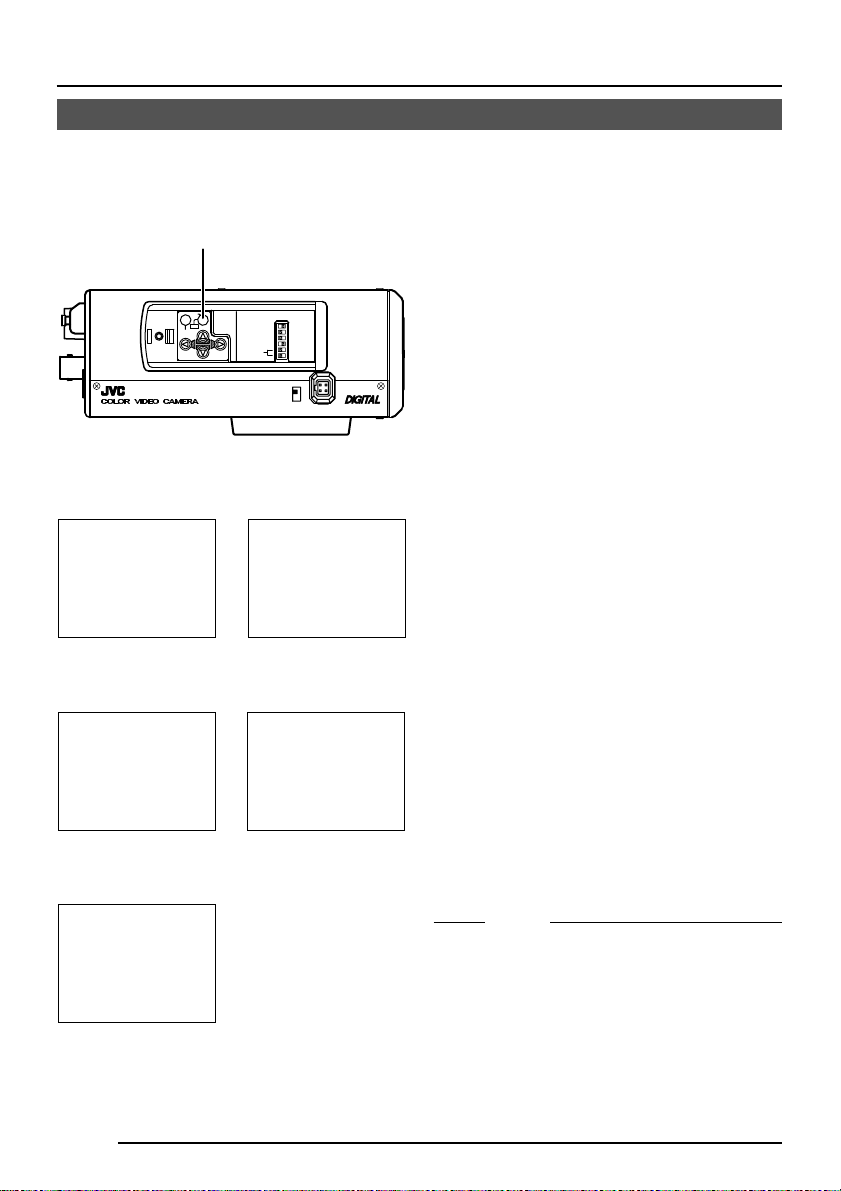
Page 8
INTRODUCTION
Controls, Connectors and Indicators
2
1
3
4
5
7
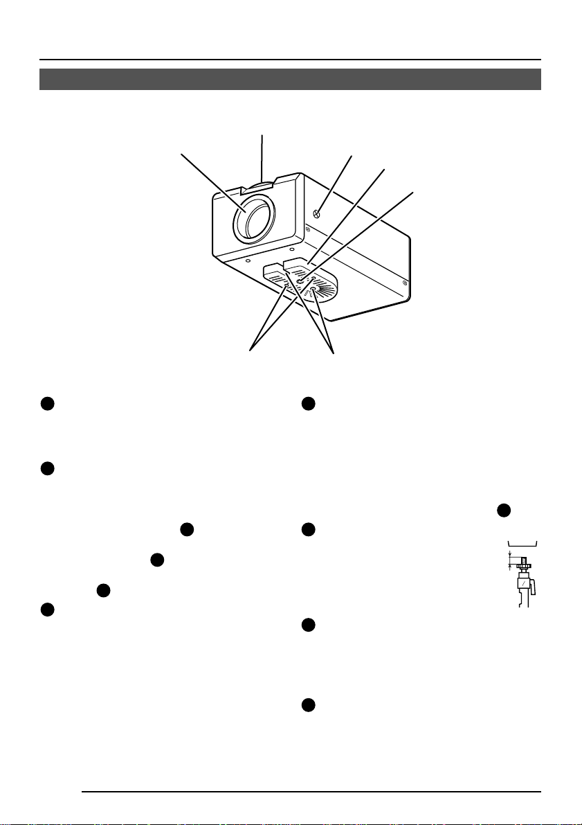
Lens mount
1
This means to attach the lens.
This is applicable to both the C-mount
lenses and CS-mount lenses.
Back focus adjustment ring
2
Adjusting the back focus during lens
installation.
When readjustment is required, loosen
the locking screw
counterclockwise and turn the back focus
adjustment ring 2.
After the adjustment, tighten the locking
screw 3 again.
[BF LOCK] Back focus locking screw
3
This serves to fix the back focus-adjusting
ring.
by turning it
3
6
Camera-mounting bracket
4
The bracket has been attached on the
bottom of the camera before shipment. It
can also be attached on the top
according to the circumstance.
T o re-attach the brac ket use the threaded
holes at the top, with the camera
mounting bracket fixing screws
Camera-mounting screw
5
hole (1/4 -20UNC)
Use this hole when mounting
the camera onto a fixer, pan/
tilt unit, and the like. (Use a
screw shorter than 7 mm.)
Rotation-preventive hole
6
Make use of this rotation-prev entive hole
to prevent any fall when mounting the
camera. Make sure that the camera is
securely mounted.
Camera mounting bracket fixing screws
7
(×2: M2.6 × 6 mm)
Be sure to use a 6 mm long screw.
7
MAX.
7
.
mm
E-8
Page 9

!
@
#$
SET
AWC
MENU
Cover
8
The cover opens if it is pulled to the left
while being pushed.
[VIDEO/DC] Iris Selector Switch
9
This is set according to the type of lens
when an automatic iris control lens is
used.
VIDEO: In case of lens with EE amp built-
in.
DC: In case of lens without EE amp
built-in.
At time of factory shipment
VIDEO: TK-C1460E
(
DC: TK-C1460U
[IRIS] Iris Terminal
10
)
This is connected to an automatic iris
control lens.
( Page 15)
[MENU] Menu Button
11
When the button is pressed, a menu
screen is brought up.
( Page 23)
CAMERA
SETUP
8
%
INT/GL
ON
LL
SIMPLEX
ON
^
&
*
IRIS
9
0
[SET/AWC] Set. Auto White Control
Button
SET: Press this button to display a sub-
menu.
( Page 23)
AWC: If this button is kept pressed for
more than 1 second, a one-pushauto-white-balance function works
and sets the white balance. Once
it is set, even if colour temperature
changes, white balance does not
change. It is also possible to make
fine adjustments on the set white
balance.
( Page 22,31,37)
EXT TERM-OFF
DUPLEX
RX TERM-OFF
NOT USED
VIDEO
DC
12
E-9
Page 10

INTRODUCTION
Controls, Connectors and Indicators (Continued)
[ , , , ] Up-and-down, left-and-
13
right Button
These buttons select items on the menu
screen and change a set value.
( Page 23)
[EXT .TERM-ON/OFF] Terminal On/Off
14
Switch of External Synchronization
Signal
This is a terminating ON/OFF switch for
the external synchronization input signal.
When this is switched ON, termination is
executed via a 75 Ω resistor.
ON: terminates at 75Ω.
OFF: does not terminate at 75Ω.
(ON: At time of factory shipment)
[INT/GL, LL] Selector Switch for
15
Synchronizing System
This switch can set a synchronizing system
of the camera.
INT/GL:
This is set for internal synchronization
(INT) or external synchronization (GL).
LL (Line Lock):
The camera’s v ertical synchronization is
locked to the AC 24V po wer line frequency .
When switching between multiple cameras
using a switcher, selecting this mode and
adjusting the vertical phase can reduce the
monitor sync disturbances occurring when
the camera image is switched. (This cannot
be used in regions where the power
frequency is 60 Hz (50 Hz) ( ): TK-C1460U)
(INT/GL: At time of f actory shipment)
[DUPLEX, SIMPLEX] Selector Switch
16
for T ransmission System
If the setting is changed, be absolutely
sure to switch on the power again.
DUPLEX:
This switch sets to DUPLEX when the
transmission between the camera and a
remote control unit is in a duplex system
(two-way).
SIMPLEX:
This switch sets to SIMPLEX when the
transmission between the camera and a
remote control unit is in a simplex system
(one-way).
(DUPLEX: At time of factory shipment)
[RX.TERM-ON/OFF] RX Signal T erminal
17
ON/OFF Switch
This sets whether or not the signal
between RX + and RX – on the back
should be terminated at the value of
110Ω resistance.
ON: terminates.
OFF: does not terminate.
If the system including the camera is the
M.DROP (Multi-drop, RS-485) system,
only the camera mounted at the terminal
of control signal cable is set to “ON” and
the other camera is set to “OFF”. In case
of the M.DROP system, it becomes
necessary to set the Machine ID. ( Page
35)
If the system including the camera is the
P T O P (Point to Point, RS-422A) system,
set this switch of all the cameras to “ON”.
The item STYLE on the COMMUNICATION screen sets M.DROP or P TO P
( Page 35)
(ON: At time of factory shipment)
NOT USED
18
This cannot be used. Do not switch.
20
E-10
Page 11

DC12V
(
AC24V
-
+
12
)
TX+TX
CLASS 2 ONLY(U TYPE)
ISOLATED POWER ONLY
(E TYPE)
ABCD
-
RX+RX
⁄
GND
AUX
-
fi
SYNC IN
›
[DC 12V , A C 24V] Po wer input terminals
19
To input DC 12V or AC 24V power.
[TX+A, TX-B, RX+C, RX-D] Control
20
signal connection terminals
Terminals for inputting signals with
electrical characteristics conforming to
the EIA/TIA RS-422A or RS-485 standard.
( Page 10
[AUX, GND] Auxiliary Input/Output
21
Terminals
If there is any change in the area set on
the MOTION DETECT screen, these
terminals output the corresponding
signals. ( Page 34)
These terminals also output the B&W/
COLOUR signal. ( Page 30)
[Open-collector low signal. Maximum
voltage 30V, current 30mA.]
When carrying out B&W/COLOUR
switching using the control signal, the
signals are input through these terminals.
( Page 30)
[B&W: make; COLOUR: break]
[Y/C OUT] Y/C output connector
22
This 4-pin connector outputs the luminance
and chrominance signal.
• Pin configuration of Y/C OUT connector
RX.TERM switch)
17
POWER
VIDEO OUT
Y/C OUT
¤
SEE INSTRUCTION
MANUAL
4
2
Pin No. Signal
1 GND
2 GND
3 Luminance (Y)
4 Chrominance (C)
[VIDEO OUT] Video signal output
23
connector
This BNC connector outputs a composite
video signal. Connect this to the video input
connector of a video monitor, s witcher, etc.
[POWER] Power indicator lamp
24
This lamp lights when power is supplied
to the camera.
[SYNC IN] Sync signal input connector
25
This BNC connector accepts the input of
an external sync signal such as a composite
video (VBS) or black burst (BB) signal.
When a sync signal is input into this
connector, the camera operation is
automatically synchronized with the
external sync signal.
To terminate this connector at 75Ω, turn
ON the EXT.TERM switch
3
1
.
14
E-11
Page 12
TO CAMERA
DATA I / O
RX
RX
TX
TX
COM
COM
9/1
10/2
11/3
12/4
13/5
14/6
15/7
16/8
COM
COM
COM
CAMERA
SW
UNIT
ALARM
AUTO
MONITOR
OUTPUT
MONITOR
VIDEO INPUT
VIDEO OUTPUT
OUTPUT
ON
POWER
OFF
ON
AC INPUT
L
L
CONNECTION/INSTALLATION
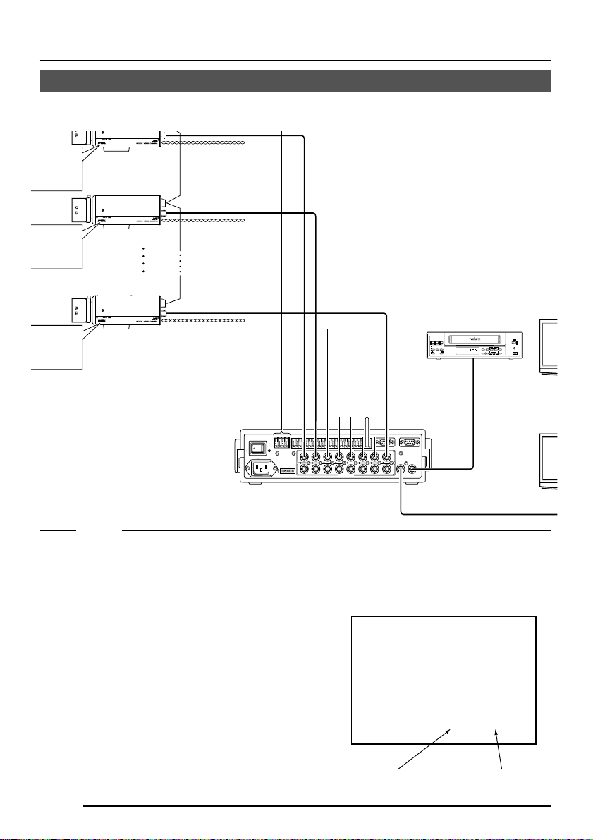
RM-P2580 System
System with up to 8 cameras
ALC
Av Pk
Camera 1
MACHINE ID:1
(Menu screen)
RX TERM: OFF
L H
(switch)
Av Pk
Camera 2
MACHINE ID:2
(Menu screen)
RX TERM: OFF
(switch)
L H
Av Pk
Camera 8
MACHINE ID:8
(Menu screen)
RX TERM: ON
(switch)
LEVEL
ALC
LEVEL
ALC
Camera
TK-C1460
Camera
TK-C1460
Camera
TK-C1460
Control signal cable
Video signal cable
Power
cable
AC24V
or
DC12V
AC24V
or
DC12V
AC24V
or
DC12V
CAM SW
•••••
OUT
Time lapse VCR
REC
STOP/EJECT
REC
CHECK
VIDEO CASSETTE RECORDER
PAUSE/
STILL
PLAY
REVERSE
FFREW
VIDEO IN
COUNT/
SHIFT/TRACKING
MENU
CLOCK
SET/V.LOCK
TIME
TIMER
MODE
REC
MONITOR
SR-L910
OPERATE
OPE. LOCK
RESET
/CANCEL
AL/PL
RESET
+
-
-
TX
COM
RX
TX
4312 8756
ON
CAMERA
DATA I / O
1 2 3 4 5 6 7 8
COM
9/1
10/2
1
2 3 4 5 6 7
1
2 3 4 5 6 7
11/3
SW
12/4
13/5
14/6
15/7
VIDEO INPUT
VIDEO OUTPUT
COM
16/8
COM
UNIT
COM
ALARM
AUTO
CAMERA
COM
SW
MONITOR
SERIAL-2SERIAL-1
OUTPUT 2
8
MONITOR
MONITOR
OUTPUT
OUTPUT
1
MONITOR
8
OUTPUT 1
MONITOR
2
TO
CAMERA
Remote Control Unit
RM-P2580
TO CAMERA
+
RX
When controlling with any system except the RM-P2580, execute proper settings using
switches and menu screens according to the systems used. ( Page 14)
MEMO
• When operating a system using the RM-P2580, several cameras (up to 16) can be
connected and used on one control signal cable. Consequently , an incorrect s witch setting
on just a single camera will cause the entire system to work incorrectly.
• Confirm switch settings on the screen as follows.
q Confirm that the image from the camera to be checked
is displayed on the monitor.
w Turn OFF and then ON the AC 24 V power to the
camera to be checked.
e The camera begins the initial operation and charac-
ters similar to those shown in the illustration on the
right appear on the monitor screen.
r Confirm that “DUPLEX” and “ID-□□ ” are displayed
and that the ID number is the correct number (the
number should be the same as the number of the
VIDEO INPUT terminal to which the camera is connected on the rear panel of the RM-P2580).
t If wrong, set the camera ID again.
“DUPLEX” should
be displayed.
MONITOR screen
(example showing camera ID as “05”)
PROT OOLDUPLEXID-05C :
The number shown in the
□□ part of ID-□□
should be correct.
E-12
Page 13

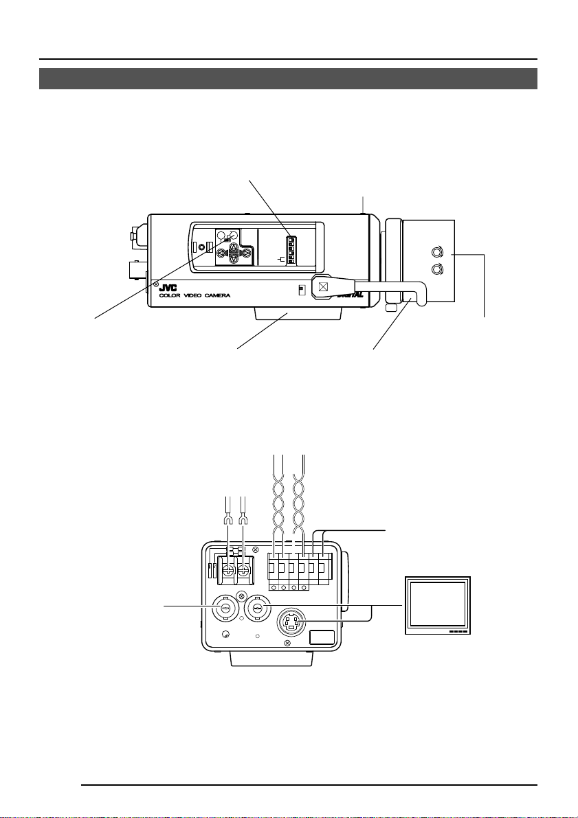
Connecting the control signal cable
(Use a twisted-pair cable for connection. Page 17.)
Camera 1
control signal
connection terminals
+
A
TX
TX B
+
C
RX
RX
D
Camera 2
control signal
connection terminals
TX+ A
B
TX
RX
+
C
RX D
RM-P2580
A RX
+
B RX
C TX
+
D TX
Connect:
Camera TX+ to RM-P2580 RX+
Camera TX– to RM-P2580 RX–
Camera RX+ to RM-P2580 TX+
Camera RX– to RM-P2580 TX–
The A B C D marks indicated on both the
camera terminals and the RM-P2580 terminals facilitate correct connections. Connect
the terminals with identical marks.
Setting the switches ( Page 10)
Select the synchronization method of the
camera image.
Set the switch on all cameras to LL (Line Lock)
and match with the V. PHASE.
EXT TERM-OFF
SET
CAMERA
SETUP
EXT TERM-OFF
ON
AWC
MENU
LL
INT/GL
DUPLEX
SIMPLEX
ON
RX TERM-OFF
NOT USED
IRIS
VIDEO
DC
DUPLEX
RX TERM-OFF
NOT USED
INT/GL
ON
LL
SIMPLEX
ON
( Page 26.)
Set this switch to the DUPLEX
* If the setting is changed, be absolutely sure to
switch on the power again.
Set this switch to ON (signal termination ON)
only on the camera placed at the end of the
control signal cable.
Set to OFF on all other cameras.
Setting on the MENU screen ( Page 35)
* If the setting is changed, escape from the menu screen once, and definitely switch on the power again.
MMCO UN I CAT I ON
S T LE M. DROPY
MA H NE DII 1C
When connecting
● Turn OFF the power supply to all equipment to be used before making connections.
● Carefully read the Instructions for each piece of equipment to be used before making
connections.
● For the appropriate connection cab les and the length of these, carefully read “Connections
on the back” on page 16.
● The control signal cable cannot be used for loop connection.
Set to M.DROP
Set to M.DROP when the RM-P2580 is used
as a remote control unit. When controlling
from another machine, make sure that it
matches the communication system used.
MACHINE ID setting switches
Set this item to match the RM-P2580 VIDEO
INPUT terminal number for each camera.
E-13
Page 14
CONNECTION/INSTALLATION
Procedures
Execute connection/installation according to the procedures described below.
Turn OFF the power supply to all equipment to be used before making carefully.
4.
7.
Auto white balance
control adjustment
( Page 22)
Setting the switches
( Page 10)
SET
MENU
3.
Mounting the camera
( Page 18)
CAMERA
SETUP
To controlling systems
such as RM-P2580
EXT TERM-OFF
INT/GL
DUPLEX
RX TERM-OFF
IOT USED
6.
Back focus adjustment
( Page 21)
ON
LL
SIMPLEX
ON
VIDEO
DC
1.
Mounting the lens
( Page 15)
Av Pk
ALC
LEVEL
L H
5.
Lens adjustment
( Page 20)
2.
Connections
( Page 16)
E-14
Genlock sync
signal generator
DC 12V/AC 24V
power supply
-
+
1
2
AC24V
DC12V
SYNC IN
VIDEO OUT
POWER
TX+TX
CLASS 2 ONLY(U TYPE)
ISOLATED POWER ONLY
(E TYPE)
ABCD
-
RX+RX
AUX
-
Y/C OUT
SEE INSTRUCTION
MANUAL
To alarm terminals
such as switches
GND
Monitor
Page 15

Mounting the lens
Mount the lens according to the procedures described below.
1.
Before mounting a lens, check whether
it is a C-mount or CS-mount lens.
T o change the mounting method, loosen
the back-focus locking screw (M 2.6)
using a Phillips head screwdriver, turn
the back-focus adjusting ring with your
fingers or the screwdriver and change
the mounting method.
As regards the dimension (b) of the area
to which the lens is to be installed as
illustrated on the left diagram, use the
one with less value than what’s shown
in the table below.
For both the C-mount and CS-mount,
never use whate ver exceeds the dimension (b), as such will not allow normal
installation and damage the inner part
of the camera, resulting in a malfunction.
Lens Flange back (c) Dimension (b)
C mount lens 17.526mm 5.5mm or less
CS mount lens
The F mark indicates a focal point.
3.
(b)
VIDEO
DC
K
C
O
L
F
B
F
(c)
2.
IRIS
VIDEO
DC
4.
12.5mm 5.5mm or less
3
1
2.
Mount the lens on the camera by turning
the lens clockwise. Adjust its position.
3.
42
When using an auto-iris lens with an EE
amplifier, turn the switch to the “VIDEO”
side. When no EE amplifier is equipped,
turn the switch to the “DC” side.
3
1
4
2
Attached 4 pin plugs
CAUTION:
Always attach the ferrite core (supplied) to
the lens cable.
( Page 42)
4.
If the lens has an auto-iris mechanism,
connect the lens cable after checking the
pin arrangement.
If the lens cable has a different type of
plug, use the 4-P plug supplied.
Lens DC IRIS VIDEO IRIS
Pin No. (does not contain EE amplifier) (contain EE amplifier)
1 Brake
2 Brake
3 Drive
4 Drive
–
+
+
–
9V [max 50mA]
NC
VIDEO
GND
3
1
4
2
E-15
Page 16
CONNECTION/INSTALLATION
Connections on the back
Po wer supply
-
+
1
2
AC24V
DC12V
SYNC IN
POWER
CLASS 2 ONLY(U TYPE)
ISOLATED POWER ONLY
VIDEO OUT
(DC 12 V or AC 24 V)
GND
-
RX+RX
AUX
-
Y/C OUT
SEE INSTRUCTION
MANUAL
TX+TX
(E TYPE)
ABCD
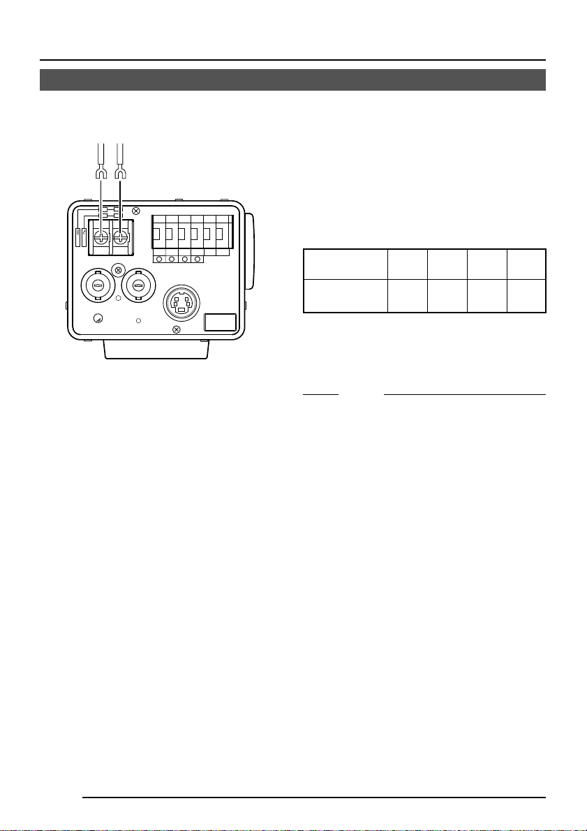
Connect the DC 12 V or the AC 24 V power
supply to the DC 12V/AC 24V terminals. To
prevent connection errors or a cable
disconnection, we recommend the use of lug
plates for the connections.
The following table shows the connection
distances and connection cables provided
that 2-conductor VVF cables (vinyl-insulated
vinyl sheath cables) are used.
Maximum extension
(reference)
Conductor
diameter
100 m 260 m 410 m 500 m
1.0∅mm 1.6∅mm 2.0∅mm 2.6∅mm
and more and more and more and more
MEMO
• If thin cables are used (i.e. with a high
resistance), a significant voltage drop will
occur when the unit is at its maximum
power consumption. Either use a thick
cable to restrict the voltage drop at the
camera side to below 10%, or place the
power supply near to the camera. If
voltage drop occurs during operation, the
performance will be unstable.
• Attach the cable conductors so that they
do not come into contact with the drop
prevention wires.
• Do not allow input from both a DC 12 V
and AC 24 V power supply at the same
time.
• When using a DC 12 V power supply,
ensure that the polarities of the cable are
correct.
• The AC 24 V power supply should
conform to the following:
TK-C1460U Class 2 only
TK-C1460E Isolated power supply only
E-16
Page 17

Control signal cables
These cables should be connected only when
it is required to control the camera using the
RS-442A or RS-485 signals. The use of 0.65
4-conductor twisted pair cables is recommended. With these cables, the maximum extension distance is 1,200 m.
Genlock connection
With some systems, when the external sync
signal is a composite video or black burst signal genlocking by applying an external sync
input requires the horizontal phase (H
PHASE) and colour phase (SC COARSE) to
be adjusted.
A
TX+
B
TX
-
C
RX+
D
RX
-
Connect to the other
side in pairs like this.
Connect to the other
side in pairs like this.
• Genlocking is not possible with a signal
containing too much jitter, such as a VCR
or videodisc playback signal.
• For details, consult a JVC authorized
dealer.
MEMO
E-17
Page 18
CONNECTION/INSTALLATION
Mounting the camera
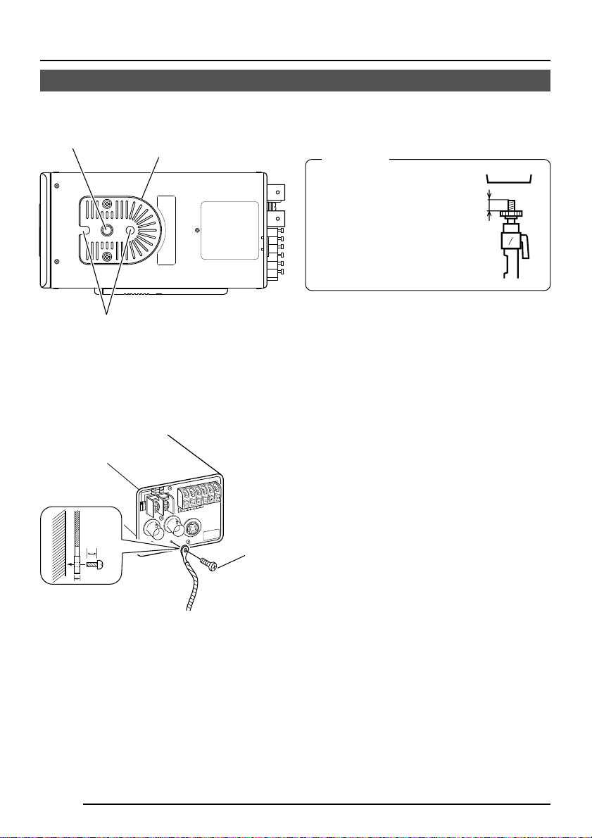
When mounting the camera on a fixer, pan/
Camera mounting
screw hole
Camera-mounting bracket
tilt, etc., use the camera mounting screw hole
located on the camera-mounting bracket.
CAUTION:
Use the screw with a
length shorter than 7mm
from a camera-mounting
face.
MAX.
7
mm
Rotation prevention hole
-
+
2
1
AC24V
DC12V
6mm
2mm
SYNC IN
POWER
VIDEO OUT
X
T
(E TYPE)
ISOLATED POWER ONLY
A
CLASS 2 ONLY(U TYPE)
-
X
T
+
B
X
R
+
CD
X
R
Y/C OUT
G
X
U
A
-
IN
E
E
S
T
C
U
R
U
N
A
M
D
N
-
T
S
N
IO
L
A
M3 x 6mm
Furthermore, make use of the rotation
prevention hole to prevent the camera from
falling and securely mount the camera.
Special precautions must be taken for
mounting the camera on a wall or a ceiling.
We are not liable for any damage caused by
improper installation.
Fall Prevention
• Exercise maximum caution when
installing the unit to the wall or ceiling. You
should not engage in the installation work
yourself. Ask a prof essional to do the job,
since the fall of the unit can result in
injuries and accidents.
• When installing the unit on a fixer, Pan/
Tilt unit, etc., make sure to install it firmly
using a rotation-preventing hole provided
to prevent f all.
• To prevent fall, connect the unit to a
section with sufficient strength (ceiling
slab or channel) using a fall prevention
wire such as a wire chain and the like.
Use the screw hole on the back of the unit
for installation.
Pay utmost attention to the length of the
wire, too.
• Specified screw (M3 × 6 mm)
Never use any screw longer than the
specified length as the inside can be
damaged.
E-18
Page 19
q
w
Cameramounting bracket
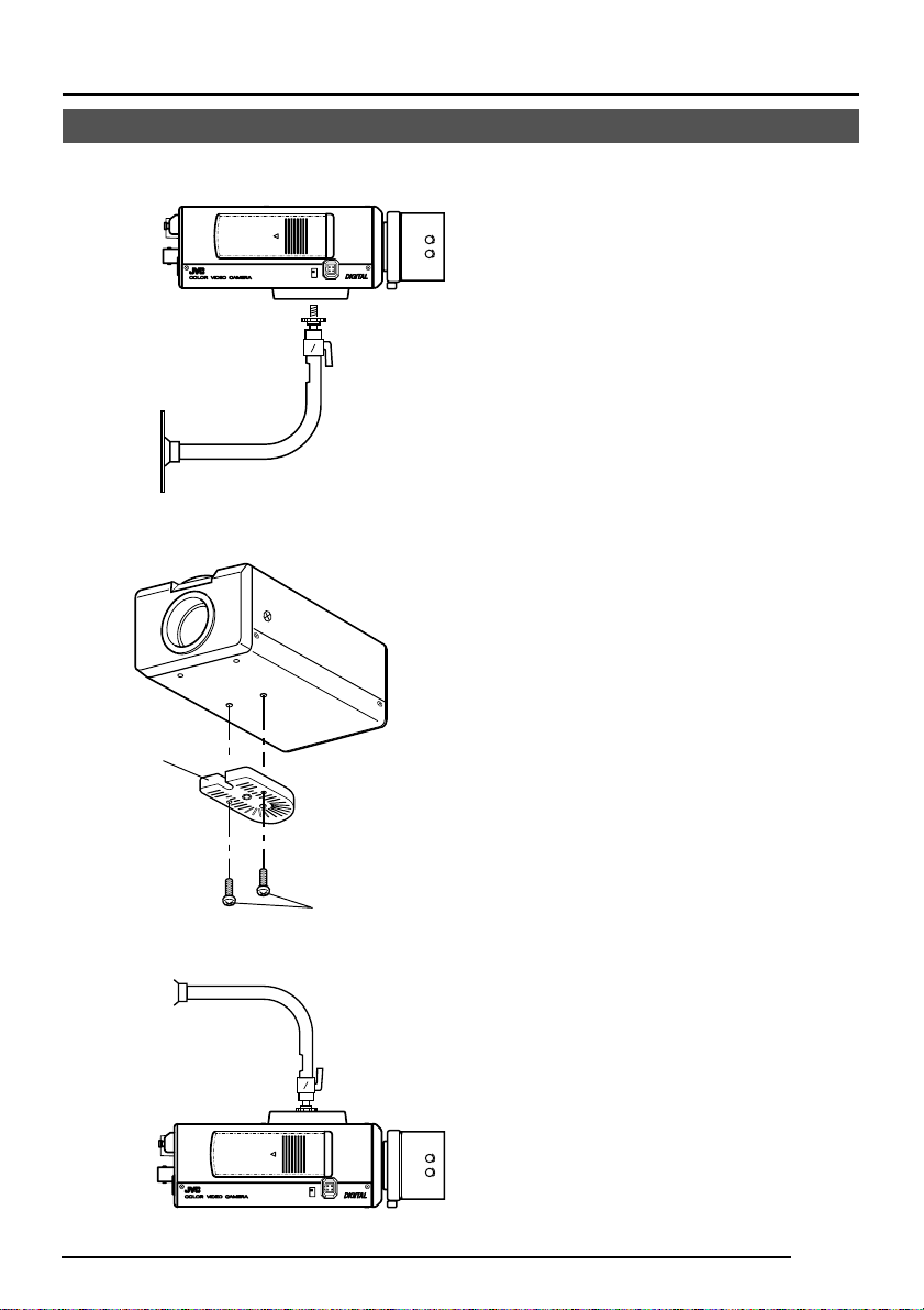
Installation of camera
• Mounting from the bottom
This camera is originally designed to be
mounted from the bottom, as shown q.
IRIS
VIDEO
DC
The hole is standard photographic panhead screw size (1/4-20 UNC). Example
the Fixing unit or Pan/Tilt unit.
• Mounting from the top
Remove the CAMERA MOUNTING
BRACKET from the bottom of the camera
by removing two fixing screws as shown
w. Attach the CAMERA MOUNTING
BRACKET to the top, then mount the
camera on the Fixing Unit as shown e.
Make sure that two original screws are
used when mounting the CAMERA
MOUNTING BRACKET. Be sure to use a
6 mm long locking screw f or the camer amounting bracket.
(This camera is used indoor and under
similar conditions.)
e
Fixing screws
IRIS
VIDEO
DC
E-19
Page 20

CONNECTION/INSTALLATION
Lens adjustment
Connect the camera according to the connection method, turn it on, display an image on the
monitor, and check the image . The camera has been factory-adjusted to the best position, but
it may need to be adjusted according to the object conditions or combination of lenses. If the
image is unnatural, adjust it as follows: (Also read the instruction manual of the lens.)
LEVEL
adjustment
L H
LEVEL
ALC
Av Pk
ALC adjustment
(Does not operate.)
MEMO
Note that the lens cannot make ALC adjustments. Mak e ALC adjustments using the item
AVERAGE: PEAK on the menu.
( Page 26)
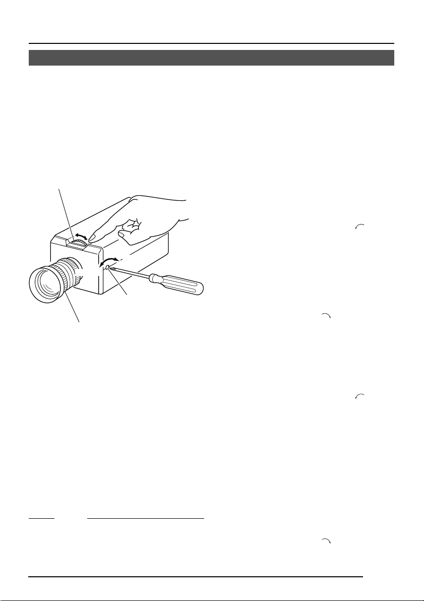
• LEVEL adjustment
Monitor screen
Too bright Counterclockwise (Toward L)
Too dark Clockwise (Toward H)
LEVEL turning direction
MEMO
• If the sensitivity adjustment LEVEL is
turned excessively to L, the sensitivity increases because of the AGC function of
the camera, and the image looks grainy.
• If the video iris lens is set to too low a level,
malfunction such as the hunting phenomenon, in which the iris opens or closes
unintentionally, may occur.
In such a case, first set LEVEL potentiometer on the lens to the H (iris open) position then adjust it to the optimum level.
E-20
Page 21
Back focus adjustment
Back focus adjustment
Be sure to make back-focus adjustments when changing the lens mounting method or using
a different lens. If required, adjust it as follows:
● To make accurate back focus adjustments, use the electronic shutter and the ND filter,
and carry out the following adjustments in a state where the lens iris is released. (The ND
filter acts to reduce the amount of incident light entering the lens evenly over the entire
wavelength band.)
Back focus
adjustment ring
Tighten
K
C
O
L
F
Loosen
Lens focus ring
MEMO
Focus setting can differ on the color and on
the black and white screen. Make adjustments so that the focus will come to the optimum on both screens.
B
Back focus locking
screw (M2.6)
• With a fixed-focus lens
If the focus can not be adjusted correctly by
rotating the lens focus ring, adjust the back
focus as follows.
1.
Loosen the back focus locking screw by
turning it counterclocckwise (
screwdriver.
2.
Shoot a pattern closely.
3.
Turn the lens focus ring to ⬁.
4.
Turn the back focus adjustment ring to
focus at the best point.
5.
Tighten the back focus locking scre w by
turning it clockwise (
• With a zoom lens
If the image is out of focus when zooming
(telephoto wide-angle), adjust the camera as
follows:
1.
Loosen the back focus locking screw by
turning it counterclocckwise (
screwdriver.
2.
Shoot a comparatively dark scene with
thin lines.
3.
Set the lens to the maximum telephoto
position, and adjust the lens focus.
4.
Set the lens to the maximum wide-angle
position, and turn the back focus ring to
adjust the focus.
(Repeat steps
times.)
5.
Tighten the back focus locking scre w by
turning it clockwise (
3.
).
and 4. two or three
).
) with a
) with a
E-21
Page 22
CONNECTION/INSTALLATION
Auto white balance control adjustment
Each light source has its own colour temperature. Therefore, when the main light source
lighting an object is changed, the white balance should be adjusted again by pressing the
AWC button.
AWC button
MENU
AWC OPERATION
DURING OPERATION
AWC NG : OBJECT
OBJECT ERROR
1.
Place a white object under the same
lighting condition as the object to be shot
and zoom in to fill the screen with white.
SET
CAMERA
SETUP
EXT TERM-OFF
RX TERM-OFF
NOT USED
DUPLEX
ON
LL
INT/GL
SIMPLEX
ON
VIDEO
IRIS
DC
2.
When the AWC button is pressed for
approx. one sec., the white balance is
adjusted for the object being recorded.
3.
During the time when the Auto White
AWC
function is operated, "AWC OPERATION" is displayed (for approx. 0.5 sec.).
When the appropriate white balance is
acquired, "AWC OK" is displayed.
4.
Error message display
AWC OK
● NG : OBJECT
Displayed when there is not enough
white colour on an object or the colour
DISPLAYING RESULT
temperature is not suitable.
By taking a shot of a white object to
fill the screen, adjust the white balance
again.
● ERROR : LOW LIGHT
Displayed when the light is low. In-
AWC ERROR : LOW LIGHT
crease the illumination then re-adjust
the white balance.
● ERROR : HIGH LIGHT
LOW LIGHTING
Displayed when the light is too bright.
Decrease the illumination then re-adjust the white balance.
AWC ERROR : HIGH LIGHT
OVER LIGHTING
E-22
MEMO
Even if you press the AWC button, the white
balance will not be re-adjusted during the
operation in the black-and-white mode.
Page 23
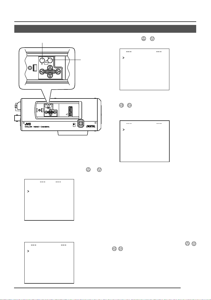
MENU SETTING
Setting the menu
MENU button
SET
CAMERA
SETUP
AWC
MENU
SET
CAMERA
SETUP
EXT TERM-OFF
..
RX TERM-OFF
NOT USED
DUPLEX
ON
LL
INT/GL
SIMPLEX
ON
VIDEO
DC
MENU
1.
Press the MENU button.
The MENU screen is displayed.
2.
Set the cursor (>) to a desired
sub-menu using the
button.
MENU
SYNC ADJUST..
ALC SETT I NGS
V I DEO ADJ UST
MODE ESLECT
MOT I ON
COMMUNI CAT I ON
FAC TORY SET T I NGS
3.
Press the SET button.
The selected sub-menu screen is
displayed.
IIRSLEVEL NORMAL
AEVRAEG:PEAK 82:
SUTHTERExDR)(
ACGMODE
SNSEEUP OFF
PIORRITY –––
BCLOFF
..
..
..
TECT
..
E
D
..
LACSETTINGS
NRMALO
2dB0
SET button
IRIS
,
4.
Use the , button to set the
cursor (>) to a desired item.
LACSETTINGS
IIRSLEVEL NORMAL
AEVRAEG:PEAK 82:
SUTHTERExDR)(
ACGMODE
SNSEEUP OFF
PIORRITY –––
BCLOFF
5.
Change the set value using the
NRMALO
2dB0
, button.
Change of the set value displays a
change mark (∗).
LACSETTINGS
I∗IRS LEVEL -5
AEVRAEG:PEAK 82:
SUTHTERExDR)(
ACGMODE
SNSEEUP OFF
PIORRITY –––
BCLOFF
If you wish to change the set values of
another items, repeat items
above.
6.
Press the MENU button.
The screen returns to the previous one
(MENU screen).
7.
Press the MENU button.
The screen returns to the normal screen
(quitting the menu display).
* When the setting is executed using the RM-
P2580, use a joy stick instead of the
button.
NRMALO
2dB0
2.
to
5.
E-23
Page 24
MENU
SYNC ADJUST
VIDEO ADJUST
MODE ESLECT
ALC SETT I NGS
COMMUNI CAT I ON
FACTORY SETTI NGS
MOT I ON
D
E
TECT
SYNC DAJUST
VPHASE 0
HPHASE 0
SC ECOARS 0
SC F I NE 1 2 8
DEVI O ADJUST
WH T E B AL E ATWNC
A
I
CO OUR L E NORMALEL
V
L
EN ANCE LE NORMALEL
V
H
PEESTAL LE NORMALEL
V
D
AUOBLAC K OFFTL
C
T
TIMO ON DE T EC T
MO E OFFD
LE EL NORMALV
AR A EDIE
ALRMTI EM10sA
DEONSTRA TIN
O
M
CTFA ORY SE NGSTT I
CA CELN
CL A W I(HOUT T I T L E )RTE
C
DATA CLEARED
LA()RALLE
WH I T E BALANCE CONTROL
AWC SET . .
RB
::
MG
::
g
.
.
..
..
..
..
..
..
..
T ..
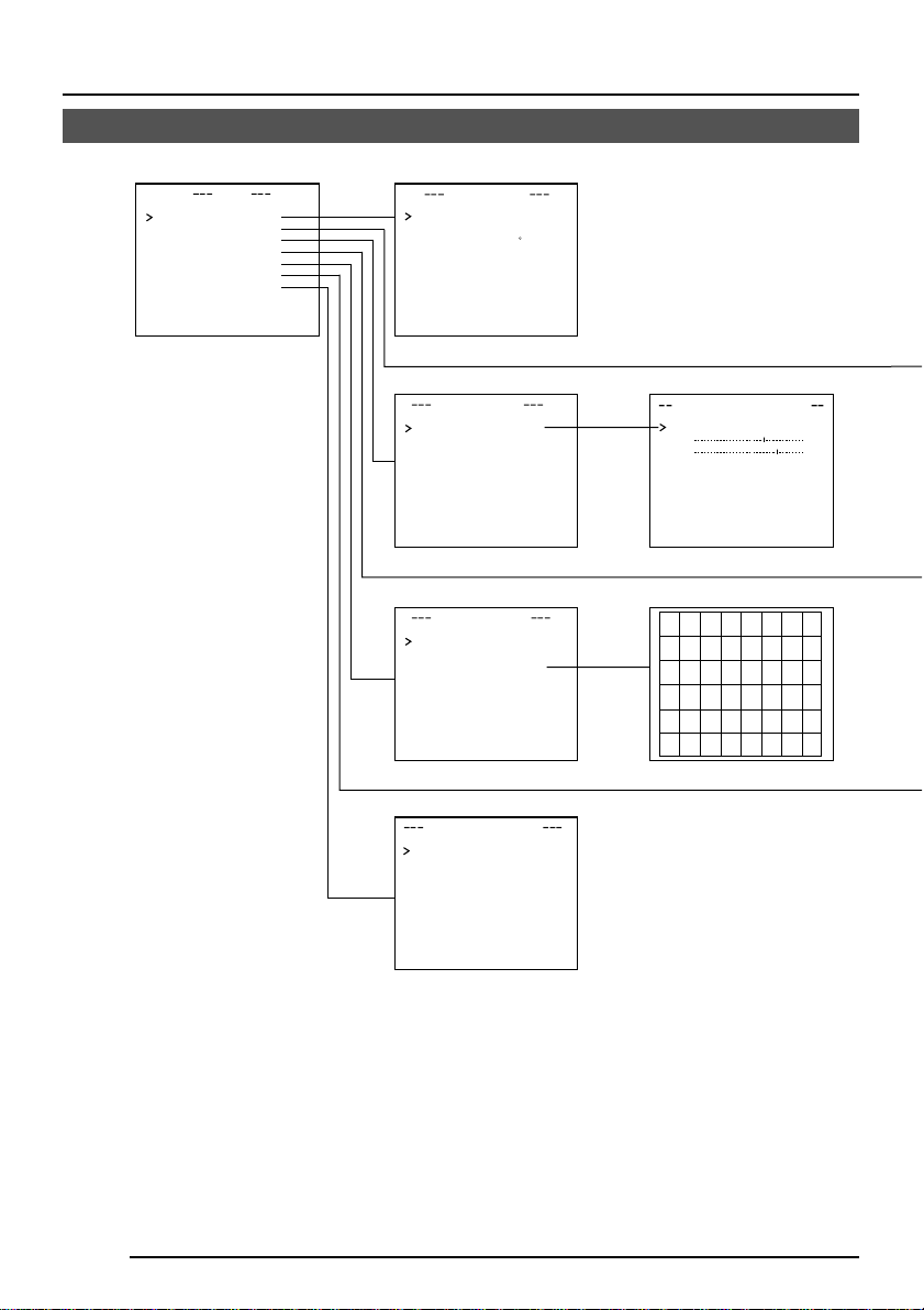
MENU SETTING
The flow of menu screen
Page 26
Page 37
Page 39
Page 31
Page 34
Page 35
E-24
The word “COLOUR” is displayed as “COLOR” on the TK-C1460U.
Page 25

Page 26
LACSETTINGS
IIRSLEVEL NORMAL
AEVRAEG:PEAK 8 2:
SUTHTERExDR)(
ACGMODE
SNSEEUP OFF
PIORRITY –––
BCLOFF
B&W/COLOUR MODE
Page 32
MODE SE LEC T
CAMERA T I T L E ED I T . .
REVERS E MODE OFF
ALM . T I T L E S ZEI D OUBLE
ALARM COLOUR WH I T E
AUX TERMINAL
D. Z00M MAX
Page 35
MMCO UNICAT ION
ST L E P TO PY
MA H N E DII – – –C
NRMALO
2dB0
(B&W IN)
x2
Page 27
SHUTT RE(ExDR)
SHUTTER SPEED
FAST L IM IT
EDxER
LLEV
SPEED
EDxR
M.
Page 36
Page 30
B&W/COLOUR MODE
B&W A U X
LEVEL
Page 38
CAMERA T
0123456789
ABCDE K L MNOPFGH I J
QRSTUVWXYZ
abcde klmnopf g hi j
qrstuvwxyz
ÄÖ ÂÊ Î Ô ÛÇÑ
Ü
äëï öüâê îô
аим тщзсЯ
WIDE T E L E
TDislayitle
ыбйну
¡¿
ITL
’
1 120/
–––
–––
–––
NORMAL
E
:-/
.,
ú
(The TK-C1460U does not display these
characters.)
E-25
Page 26

MENU SETTING
SYNC ADJUST Screen
This executes the setting regarding synchronization.
Item Functions and set values Initial value
V PHASE
H PHASE
SC COARSE
SC FINE
This adjusts the vertical synchronization to those of other cameras
when a selector switch for the synchronizing system on the side
is at LL. (50Hz (60Hz) power region only. ( ): TK-C1460U)
When it is not set to LL, “---” will appear, disabling change
the set value.
TK-C1460U
[Set value: –131 to 0 to 131]
TK-C1460E
[Set value: –156 to 0 to 156]
This adjusts the horizontal synchronization to those of other
cameras and systems when a selector switch for the
synchronizing system on the side is at INT/GL.
When external signals are not input, “---” will appear, disabling
change the set value.
[Set values: –16 to 0 to 16]
Coarse adjustment of the SC phase in gen-lock operation.
The SC phase can be varied by up to 90° in each direction.
Adjust with reference to another camera (or system) and
together with the SC FINE adjustment.
Adjust SC COARSE and SC FINE only after adjusting H
PHASE.
When it is not set to GL, “---” will appear, disabling change
the set value.
[Set values: 0°, 90°, 180°, 270°]
Fine adjustment of the SC phase in gen-lock operation.
When it is not set to GL, “---” will appear, disabling change
the set value.
[Set values: 0 to 255]
0
0
0°
128
ALC SETTINGS Screen
This makes automatic adjustments according to brightness.
Item Functions and set values Initial value
IRIS LEVEL
AVERAGE:
PEAK
Adjusts the brightness level of the video signal.
• To lower the brightness level ...Decrease the value
• To raise the brightness level.... Increase the value
[Set values: –5 to NORMAL to 5]
Sets the exposure detection as a ratio of the av erage value
and the peak value.
• AVERAGE value large: Increase the AVERAGE value
when portions other than the highlighted areas of the
screen are dark and look corrupted. (Ex. 10:0)
• PEAK value large: Increase the PEAK value when
halation occurs in the highlighted areas of the screen.
(Ex. 5:5)
[Set values: 10:0, 9:1, 8:2, 7:3, 6:4, 5:5]
E-26
NORMAL
8 : 2
Page 27

Item Functions and set values Initial value
SHUTTER
(ExDR)
* When the SHUTTER (ExDR) item is set to NORMAL, the following items
(SHUTTER SPEED, FAST LIMIT, ExDR LEVEL, and M.ExDR SPEED)
cannot be changed.
SHUTTER
SPEED
This sets the electronic shutter as well as the ExDR (Extended
Dynamic Range).
The use of an electronic shutter function enables shooting
with proper brightness, as more brightness results in higher
shutter speed.
The ExDR function allows even the shooting of a subject
having different luminous flux density by composing a picture
shot at 1/100 (1/120) sec. shutter speed with a picture shot
by a high-speed shutter. ( ): TK-C1460U
NORMAL: This fixes the shutter speed to 1/50 (1/60).
The ExDR does not function.
MANUAL: This sets the shutter speed by the item
SHUTTER SPEED on the SHUTTER screen.
The ExDR does not function.
When SENSE UP is functioning, MANUAL
cannot be selected. (Not displayed on MENU)
AUTO: This automatically switches the shutter speed
according to brightness.
The ExDR does not function.
The item FAST LIMIT on the SHUTTER (ExDR)
screen sets a maximum shutter speed value.
M.ExDR: This is used when shooting a subject with
difference in a luminous flux density in the screen
under a fixed illumination condition, and so on.
During ExDR mode, the item M.ExDR.SPEED on
the SHUTTER (ExDR) screen sets the composing
high shutter speed. It is possible to set only when
the items BLC and SENSE UP are OFF. What’s
more, the ExDR LEVEL sets the signal level of
the composing high-speed shutter.
A.ExDR: This is used when the subjects having different
luminous flux densities are continuously used
night and day in the situation where both indoor
and outdoor subjects are mixed in existence , and
so forth. During ExDR mode, the composing
shutter speed automatically varies according to
the contrast of a subject. This is set when shooting
the subject with changing brightness.
This can be set only when the item BLC is OFF.
What’s more, the ExDR LEVEL sets the signal
level of the composing high-speed shutter.
MEMO
• Do not set to A.ExDR when using a manual lens.
• When M.ExDR mode or A.ExDr mode is used, the border
between a bright part and a dark part can be coloured
(cyan, orange, etc.), but this is not a malfunction.
• When the SHUTTER (ExDR) item is set to M.ExDR or
A.ExDR, a flicker can occur under a fluorescent lamp,
mercury lamp, etc. However, this occurs by principle of
the ExDR function, and therefore this is not a
malfunction.
This sets a shutter speed when MANUAL is set.
The AUTO, M. ExDR, A. ExDR set value is displayed as
“---” and cannot be changed
[Set values: 1/120 (1/100), 1/250, 1/500, 1/1000, 1/2000,
1/4000, and 1/10000] ( ):TK-C1460U
NORMAL
1/120
(1/100)
E-27
Page 28

MENU SETTING
ALC SETTINGS Screen (Continued)
Item Functions and set values Initial value
FAST LIMIT
ExDR
LEVEL
M.ExDR
SPEED
AGC MODE
SENSE UP
E-28
This sets the fastest value of a shutter speed when AUTO is set.
The MANUAL, M. ExDR, A. ExDR set v alue is displa yed as “---” and
cannot be changed. The higher the shutter speed becomes, the more
smear phenomenon is emphasized, which is peculiar to the CCD.
[Set values: 1/1000, 1/2000, 1/4000, 1/10000, 1/20000, 1/40000, 1/100000]
This sets the signal level of the composing high-speed shutter during
ExDR mode. This is set according to the brightness of a subject.
When using M.ExDR, be sure to set M.ExDR SPEED in advance.
When the SHUTTER (ExDR) item is set to MANUAL or AUTO,
“---” appears, disabling setting.
To give priority to the low-brightness par ts of the subject…
increase the value
To give priority to the high-brightness parts of the subject…
decrease the value
[Set values: –5 to NORMAL to 5]
MEMO
• In the case of a subject with a large difference in the luminous
flux density, sometimes images do not change even if ExDR
LEVEL is varied. However, this occurrence is a peculiarity of
the unit and is not a malfunction.
This sets the composing high shutter speed when ExDR is set to M.ExDR.
Set the shutter speed in order that a subject with a high luminous flux
density (outdoor, etc.) may come out most clearly. This is d is p layed as
“---” during MANUAL, AUTO or A. ExDR and cannot be set.
[Set values: 1/500, 1/1000, 1/2000, 1/4000, 1/10000, 1/20000]
This sets a maximum gain of the AGC (Automatic Gain Control).
OFF: When the AGC function is not used.
10dB: When luminous energy is insufficient.
20dB: When luminous energy is extremely insufficient.
SUPER: When brightness is insufficient even when it is set to
• If the gain is increased, the screen gets rough in a dark place.
• If it is set to SUPER, it can sometimes consume operation time
to cope with a drastic level change.
•
When the item “B&W” is set to “AUTO”, [SUPER] is displayed when
the item “AGC MODE” is set to “SUPER”, and [20dB] is displayed
for other settings. Increase the gain up to the value displayed.
This item makes up a sensitivity should be heightened automatical-
ly when a subject becomes dark.
In case of the X32 AUTO , the sensitivity is automatically heightened
up to 32 times continuously as compared with standard.
As the sensitivity becomes higher, the shutter speed becomes
lower, resulting in unnatural motion.
If SHUTTER (ExDR) is set to MANUAL or the M.ExDR,
“---” will appear, disabling the SENSE UP function.
[Set values: OFF, X2 A UT O, X4 A UT O , X8 AUT O , X16 A UT O , X24
AUTO, X32 AUTO]
• When the magnification of SENSE UP is enhanced, the screen
can become coarse or whitish, or whitish flaws can emerge
sometimes, but this is not abnormal.
• When the item SENSE UP is set other than to OFF, a flicker can
occur under a fluorescent lamp, mercury lamp, etc. However,
this occurs by principle of SENSE UP, and therefore this is not a
malfunction.
20dB.
MEMO
1/100000
NORMAL
1/4000
20dB
OFF
Page 29
Item Functions and set values Initial value
PRIORITY
This item sets the order in which the AGC and slow shutter
speed decrease function when the object brightness
becomes low.
If B&W item of the B&W/COLOUR mode is set to AUT O, and the
AGC MODE item or the SENSE UP item is set to OFF, “---” will
appear, disabling any setting.
MOTION: Priority is given to motion.
This is suitable to a subject with quick motion,
since the AGC (automatic gain control) functions
with priority when the subject becomes dark.
PICTURE: Priority is given to image.
When the subject becomes dark, SENSE UP
(sensitivity goes up) functions with priority,
offering suitability that gives priority to image.
MOTION
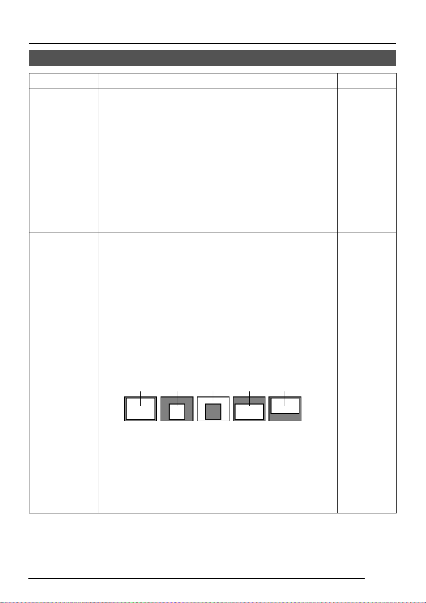
BLC
Sets the backlight compensation function. Set when a
bright light source, etc. is placed in the same direction as
the subject.
If the item SHUTTER (ExDR) is set to the M.ExDR or the
A.ExDR, “---” will appear , and the BLC does not function.
OFF: The backlight compensation function does not work.
AREA 1 to AREA 4: When the SET button is pressed, the
fixed light metering areas are displayed. Select one of
the four types. (Indicated positions on the screen are rough
guides. Execute required settings after checking and
confirming the functions on actual images.)
Light
metering
area
Light
metering
area
OFF AREA 1 AREA 2 AREA 3 AREA 4
Light
metering
area
Light
metering
area
Light
metering
area
* The indicated position on the screen should be used as
a rough guide.
EDIT 1 to EDIT 2: When the SET button is pressed, the
user light metering areas are displayed. Select one of the
two types.
“BLC EDITTING Screen” on page 36.
OFF
E-29
Page 30

MENU SETTING
ALC SETTINGS Screen (Continued)
Item Functions and set values Initial value
B&W COLOUR
MODE .....
B&W
This function sets the colour modes to colour or B&W.
When switching the mode between “colour’ and “B&W” is
carried out, the focus may be dislocated. In such a case
adjust the focus again.
Switches the mode from colour to B&W and visa-versa.
OFF : Turns the B&W mode switching function off.
ON : Sets the camera permanently to B&W mode.
AUTO : The camera automatically switches to Colour
mode when the object is bright and B&W mode
when it is dark. ( Page 40)
AUX : B&W/COLOUR switching is carried out
according to the signal input from the AUX
terminal. ( Page 41)
MEMO
• If A UTO is selected as the B&W item, the B&W/COLOUR
setting can be switched as appropriate according to the
brightness of the object, but illumination and screen
conditions may make this impossible. Moreover, when
you use infrared illumination, if the subject excessively
reflects, a B/W screen can switch to a color screen. To
make absolutely certain of B&W/COLOUR switching,
set to AUX and input the control signal to the AUX
terminal.
• If A UX is selected as the B&W item, the AUX TERMINAL
item is automatically set to B&W IN. If this changes to
anything other than AUX, the AUX TERMINAL item
reverts to the value set before the change was made.
( Page 33.)
AUX
E-30
LEVEL
When the “B&W” function is set to “AUTO”, this function
sets the signal level of the object at which the camera will
automatically switch to B&W mode.
LOW : Switches to B&W mode when the signal level of
NORMAL
HIGH : Switches to B&W mode when the signal level of
When the item “B&W” is set to other than AUTO, “---” is
displayed and the settings to the item “LEVEL” cannot be
varied.
the object indicates low illumination.
: Switches to B&W mode when the signal level of
the object indicates medium illumination.
the object indicates high illumination.
MEMO
NORMAL
Page 31

VIDEO ADJUST Screen
Adjustments are made on video signals.
Item Functions and set values Initial value
WHITE
BALANCE
Selects the white balance adjustment function. The white
balance can be adjusted manually or automatically for
light within the colour temperature range of 2500K to
8000K.
• ATW: Auto-Tracking White Balance mode.
This automatically adjusts the white balance.
• AWC: Auto White Balance Controll mode . When the
SET button is pressed, the adjustment
screen appears.
( See page 37.)
MEMO
The “---” will appear during operation in the black-and-
white mode and any setting cannot be changed.
ATW
COLOUR
LEVEL
ENHANCE
LEVEL
PEDESTAL
LEVEL
AUTO
BLACK
CTL
To adjust the colour level of the video signal.
• To make colours lighter … Decrease the value
• To make colours darker … Increase the value
[Set values: –5 to NORMAL to 5]
MEMO
The “- - -” will appear during operation in the black-andwhite mode and any setting cannot be changed.
T o adjust the contour enhancing le v el of the video signal.
• To make the picture quality harder … Increase the value
• To make the picture quality softer … Decrease the value
[Set values: –5 to NORMAL to 5]
To adjust the pedestal level of the video signal.
• To brighten picture … Increase the value
• To darken picture … Decrease the value
[Set values: –5 to NORMAL to 5]
This is set when it is difficult to view a dark part of the
image even if gain is boosted by the A GC (automatic gain
control).
ON: When a black level of the image signal is low, a
pedestal level that becomes the standard of black
is automatically elevated, making it easier to vie w a
dark part.
OFF: AUTO BLACK does not function.
MEMO
• When PEDESTAL LEVEL is set to 5, no function can
take place even if AUTO BLACK CTL is ON.
• When AGC MODE is set to OFF, no function can take
place even if AUTO BLACK CTL is ON.
NORMAL
NORMAL
NORMAL
OFF
E-31
Page 32

MENU SETTING
MODE SELECT Screen
Titles, image reversion, etc., are set.
Item Functions and set values Initial value
CAMERA
TITLE EDIT
Bring up the CAMERA TITLE, EDIT screen.
( Page 38)
–
REVERSE
MODE
ALM.TITLE
SIZE
ALARM
COLOUR
Settings are executed for image reversion.
OFF: Image does not reverse.
R-L: Left and right of the image are reversed.
U-D: Up and down of the image are reversed.
ALL: Up and down and left and right of the image are
reversed.
Set the size of the characters displayed in the case of
alarms.
ALARM
NORMAL DOUBLE
This sets the colour of an alarm title.
[Set values: WHITE, YELLOW, CYAN, GREEN]
MEMO
In the ALARM mode, the colour of camera title appears
in the ALARM COLOR set.
ALARM
OFF
DOUBLE
WHITE
E-32
Page 33

Item Functions and set values Initial value
AUX
TERMINAL
For setting the signal input or output of the A UX terminal.
MOTION: A signal is output if there is a change in the
area set on the MOTION DETECT screen.
B&W OUT: A signal is output when the camera switches
to B&W or Colour mode.
B&W IN: Set to this position when inputting the B&W/
Colour switching control signal to the AUX
terminal. ( Page 11, 30.)
MEMO
• In setting B&W OUT, if you use an infrared illuminator in
link motion, hunting can occur. To prevent this, we
recommend that you link in motion this unit and the
infrared illuminator, etc., b y control signals after setting
to B&W IN.
• If the B&W item is set to A UX, the A UX TERMINAL item
changes to [B&W IN] and can not be changed.
(B&W IN)
D-ZOOM
MAX
This function sets the maximum zoom ratio of the
electronic zooming.
[Set values: x1, x2, x4, x6, x8, x10]
MEMO
• The electronic zoom function can only be used by the
communication command of exclusive controllers (RMP2580, etc.).
• Note Picture quality deteriorates under electronic
zooming as it is accompanied by digital image
processing.
• When the electronic zoom magnification ratio is
increased, there may be blurring in the upper center left
of the screen. This is a characteristic of the main unit
and is not a malfunction.
x2
E-33
Page 34

MENU SETTING
MOTION DETECT Screen
Settings are executed about the motion detecting function that emits alarm signals when
there exists any motion in the image. Alarm signals are output from the auxiliary terminals on
the back.
Item Functions and set values Initial value
MODE
LEVEL
This sets ON/OFF of motion detecting function.
OFF: Motion detecting function does not work.
ON: Motion detecting function works.
This sets the level that detects motion.
If the item MODE is set to OFF, “---” will appear, and
settings cannot be changed.
To function with large signal level change…decrease the
value
To function with small signal level change…increase the
value
[Set values: –5 to NORMAL to 5]
OFF
NORMAL
AREA EDIT
ALARM TIME
DEMONSTRATION
This sets the range in which the motion detecting function
works.
( Page 39)
This sets the output time of the alarm signal output of
AUX terminal as well as “ALARM” display on the screen
when motion is detected.
If the item MODE is set to OFF, “---” will appear, and
settings cannot be changed.
[Set values: OFF, 5s, 6s, 7s, 8s, 9s, 10s, 15s, 20s, 30s,
1min]
MEMO
Even when the ALARM TIME item is set to OFF, an alarm
signal is output from the AUX terminal for about 500ms,
and “ALARM” is not displayed on the screen.
This is used when checking and confirming the set motion
detecting function. The detection area is shown in gray.
( Page 39)
–
10s
–
E-34
Page 35

COMMUNICATION Screen
Settings are made for the control signal-connecting terminals on the back.
If the setting is changed, be absolutely sure to switch on the power again.
Item Functions and set values Initial value
STYLE
MACHINE ID
This sets a communication system according to the
system used.
P TO P (Point to point)
This is set when a remote control unit controls a camera.
M.DROP (Multi-drop)
This is set when a remote control unit controls a plural
number of cameras.
This is set when the STYLE item is set to M.DROP. This
is the number that identifies individual cameras in a group.
No proper function can be realized if an ID number is
repeated within a system.
A combined use with the RM-P2580 necessitates the
setting together with the video input number of the RMP2580.
If the item STYLE is set to P TO P, “---” will appear, and
settings cannot be changed.
[Set values: 1 to 99]
FACTORY SETTINGS Screen
Set values are returned to initial values.
P TO P
– – –
Item Functions and set values Initial value
FACTORY
SETTINGS
The values set on the menu are returned to initial values.
CANCEL : No return to the initial value.
CLEAR : Returns set values except titles to the
(WITHOUT TITLE)
CLEAR (ALL) : Retur ns all set values including titles
Select respective set value and press the SET button. Then,
“DATA CLEARED” will appear for about 3 seconds. Be
sure not to switch off the power while the display is still on.
MEMO
However, when FACTORY SETTINGS by means of
transmitted commands, the contents of the
COMMUNICATION menu do not return to the factory
settings.
initial value.
to the initial value.
–
E-35
Page 36

MENU SETTING
CAMERA
SETUP
SET
MENU
AWC
BLC EDITTING Screen
It is possible to set freely the light metering area for backlight compensation. The 2 screens
of EDIT1 and EDIT2 can be set.
IIRSLEVEL NORMAL
AEV RAGE: P EAK 8 2:
SUTHTERExDR)(NRMALO
ACGMODE 2dB0
SNSEEUP OFF
PIORRITY MTIONO
BCL
EDIT 1 screen
LACSETTINGS
SET button
EDIT 1
Light metering
area
MENU button
1.
Set the item BLC on the ALC
SETTING screen to EDT1.
2.
Press the SET button.
The EDIT1 screen is brought up.
3.
Set the upper side and left side
of the metering area using the
button.
The sides having marks can
be changed.
SET button
EDIT 2 screen
SET button
* The indicated position on the screen
should be used as a rough guide.
E-36
Light metering
area
4.
Press the SET button.
The changeable sides of the metering
area move to the right side and base
side.
5.
Set the base and right side of the
metering area using the
button.
If the SET button is pressed once more,
the two changeable sides of the metering area return to the top and left sides.
(The EDIT2 screen can also be set
likewise)
6.
Upon completion of setting,
press the MENU button.
The screen returns to ALC SETTING
SCREEN.
* To use the set metering area, set the item
BLC to EDIT1 or EDIT2.
Page 37

Manual Adjustment of White Balance
When automatic adjustment of the white balance results in a “reddish screen”, etc., adjust the
white balance manually.
1.
SET buttonMENU button
SET
CAMERA
SETUP
AWC
MENU
DEVI O ADJUST
WH TE BAL E AWCNC
CO OUR L E NORMALEL
EN ANCE LE NORMALEL
PEESTAL LE NORMALEL
AUOBLAC K OFFTL
A
I
V
L
V
H
D
T
V
C
VIDEO ADJUST screen
WHI TE BALANCE CONTROL
AWC SE T. .
::
RB
g
::
MG
Set the WHITE BALANCE item on the
VIDEO ADJUST screen to AWC and
press the SET button.
* The WHITE BALANCE adjustment
screen appears on the monitor.
2.
Select the hue to be adjusted. (R/B or
Mg/G)
Press the
3.
Adjust the hue.
Press the
or button.
or button.
* The “ ı ” indicator mo ves in accordance
with the setting. When a setting is
changed, the “+” mar k appears at the
original position.
4.
Concluding manual white balance adjustment.
Pushing the MENU button returns the
screen to VIDEO ADJUST.
MEMO
If the mode is changed from color to blackand-white during the color phase adjustment
on the WHITE BALANCE CONTROL screen,
the VIDEO ADJUST screen will be brought
back. At this time, any adjusted v alue will not
be saved.
WHITE BALANCE
CONTROL screen
The word “COLOUR” is displayed as “COLOR” on the TK-C1460U.
E-37
Page 38

MENU SETTING
CAMERA TITLE Setting
Up to 24 characters can be selected as camera text f or each camer a. The set characters are
displayed at the bottom of the screen.
SET buttonMENU button
SET
CAMERA
SETUP
AWC
MENU
MODE S E L ECT
CAMERA T I T L E ED I T . .
REVERS E MODE OF F
ALM . T I T LE S ZEI DOUBLE
ALA RM COLOUR WH I T E
MODE SELECT screen
Space
CAMERA T
0123456789
ABCDE KLMNO PFGH I J
QRSTUVWXYZ
abcde k lmnopf g hi j
qrstuvwxyz
ÄÖ ÂÊ Î ÔÛÇÑ
Ь
длп цьвк оф
аим тщзсЯ
Character area
E
ITL
:-/
.,
’
ыбйну
ú
¡¿
1.
Select the item CAMERA TITLE
on the MODE SELECT screen,
and push the SET button.
Then, the CAMERA TITLE screen is
brought up.
2.
Select the first character from the
character area using
buttons.
The selected character is displayed
flashing on and off.
3.
Push the SET button.
The first character gets fixed and the
blinking title input area moves to the
second character.
4.
Repeat the above items 2 to 3.
It is possible to use up to 24 characters
to input the title.
5.
Push the MENU button.
The screen returns to MODE SELECT.
▲
Title input area
E-38
WD
IE LETE
TDislayitle
CAMERA TITLE screen
(The TK-C1460U does
not display these
characters.)
Page 39

Setting the MOTION DETECT Function
It is possible to set freely the area where MOTION DETECTING functions.
1.
TIMO ON DET EC T
MO E OFFD
LE EL NORMALV
AR A ED I TE
ALRMTI EM10sA
DEONSTRA T I N
MOTION DETECT screen
flash
lights gray flash
..
M
O
..
Setting screen
Select the item AREA EDIT on
the MOTION DETECT screen.
2.
Press the SET button.
The setting screen is brought up.
3.
Select the area not subject to
detection using the
button.
The area flashing ON and OFF in black
and white moves.
4.
Press the SET button.
The area not subject to detection is set,
and it turns gray (lights up).
To cancel the set area, press the SET
button again.
5.
Repeat items 3 and 4 above.
6.
Upon completion of setting,
press the MENU button.
The screen returns to the MOTION
DETECT menu.
MEMO
• Indicated positions on the screen are rough
guides.
Be sure to check and conform the positions
on the actual screen.
* It is possible to check and confirm the set
areas on the DEMONSTRATION screen.
The detection area is shown in gray.
• The MOTION DETECT function does not
work for about 5 seconds after exiting
MENU.
The motion detector is not a feature to prev ent theft, fire, etc. Even if an accident should occur
resulting in damage, we do not accept any liability.
E-39
Page 40

Output of Black-White/Color switching signal
It is possible to output black-White/color switching signal from the AUX terminal on the back
of this unit.
Set the B&W Item to AUTO.
SET buttonMENU button
SET
CAMERA
SETUP
AWC
MENU
B&W/COLOUR MODE
B&W
LEVE L
MODE S E L ECT
CAMERA T I T L E ED I T . .
REVERS E MODE OF F
ALM . T I T LE S ZEI DOUBLE
ALA RM COLOUR WH I T E
AUX TERMINAL B&W OUT
D. ZOOM MAX x2
AUX
NORMAL
1.
Select the B&W/COLOR MODE item on
the ALC SETTING screen.
2.
Press the SET button.
The B&W/COLOR MODE screen
appears.
3.
Press either the button or the
button and select the B&W item.
4.
Press either the button or the
button and set to “AUTO”.
5.
Upon completion of setting, press the
MENU button twice.
Then, the MAIN MENU screen is
brought back.
Set the AUX TERMINAL Item to
B&W OUT.
1.
Select MODE SELECT on the MAIN
MENU screen.
2.
Press the SET button.
The MODE SELECT screen appears.
3.
Press either the button or the
button and select the AUX TERMINAL
item.
4.
Press either the button or the
button and set to ”B&W OUT”.
5.
Upon completion of setting, press the
MENU button twice.
• Then, the normal screen is brought
back.
CAUTION:
When you use near infrared ray illuminations, use a lens that is compatible
with the near infrared ray illuminations.
Any lens other than the compatible one
can result in out-of-focus due to such
characteristics.
E-40
MEMO
• When you use infrared illumination, if the
subject excessively reflects, a B/W screen
can switch to a color screen.
To perform switching with higher accuracy,
we recommend that you use it by the setting
mentioned in [Control by Black-White/Color
Switching Signal From the Outside],
referring to Page 41.
Page 41

Control by Black-White/Color Switching Signal From the Outside
Carry out the following setting when you link in motion the black-white/color switching of this
unit and infrared illumination, etc., using the switching signal from the outside control de vice.
Infrared illumination, etc.
Sensor or switch
AC24V
DC12V
SYNC IN
POWER
-
+
12
CLASS 2 ONLY(U TYPE)
VIDEO OUT
TK-C1460
TX+TX
ISOLATED POWER ONLY
(E TYPE)
ABCD
-
RX+RX
MENU
AUX
-
Y/C OUT
SET buttonMENU button
SET
AWC
Switching
signal
B&W: Make signal
COLOR: Break signal
GND
SEE INSTRUCTION
MANUAL
Outside control device
It is requested that you consult our JVC dealer about connecting
devices, etc.
Set the B&W item to AUX.
1.
Select B&W/COLOR MODE on
the ALC SETTING screen.
2.
CAMERA
SETUP
Press the SET button.
• The B&W/COLOR MODE screen
appears.
3.
Press either the button or the
button and select the B&W
item.
LACSETTINGS
IIRSLEVEL NORMAL
AEVRAEG:PEAK 82:
SUTHTERExDR)(
ACGMODE
SNSEEUP OFF
PIORRITY
BCLED
B&W/COLOUR MODE
B&W/COLOUR MODE
B&W
LEVE L
NRMALO
2dB0
TION
AUX
NORMAL
T1MOI
4.
Press either the button or the
button and set to “AUX”.
Then, the AUX TERMINAL item on the
MODE SELECT screen is automatically
set to (B&W IN). Refer to Page 33.
5.
Upon completion of setting,
press the MENU button.
• Then, the ALC SETTING screen is
brought back.
CAUTION:
When you use near infrared ray illuminations, use a lens that is compatible
with the near infrared ray illuminations.
Any lens other than the compatible one
can result in out-of-focus due to such
characteristics.
E-41
Page 42

OTHERS
Installing the ferrite core
To r etain electromagnetic compatibility, use the ferrite cores provided when connecting to the lens or
the power source.
Video-iris lens
(or galvanometnc-iris lens)
Wind twice
VIDEO
IRIS
DC
ALC
LEVEL
Av Pk
L H
Ferrite core
Notes:
Install the ferrite cores within 50 mm of the camera-side connectors. (Fasten the ferrite
core with the wire clamp provided.)
For lens connection: Pass the lens cable through the f errite core twice and con-
nect it to the camera.
Specifications
DIMENSIONS (Unit: mm)
70
39
35
U1-32
55
63
138
149
E-42
42
71
41
1/4 – 20UNC
Page 43

Specifications (Continued)
Image pickup device: TK-C1460U
1/3 type IT CCD, 768 (H) × 494 (V)
TK-C1460E
1/2 type IT CCD, 752 (H) × 582 (V)
Synchronization method : Internal, Line lock, Full Genloc k
Scanning frequency: TK-C1460U
(H) 15.734 kHz, (V) 59.94 Hz
TK-C1460E
(H) 15.625 kHz, (V) 50 Hz
Resolution: 480 TV lines (H)
VIDEO OUT: Composite video signal 1 V (p-p), 75Ω (BNC)
Y/C OUT: TK-C1460U (4-pin)
Y: 0.714V(p–p), 75Ω
C: 0.286V(p–p), 75Ω
TK-C1460E (4-pin)
Y: 0.7V(p–p), 75Ω
C: 0.3V(p–p), 75Ω
Video S/N ratio: 50 dB (AGC OFF)
Minimum required illumination: 0.8 lx (50%, F1.2, AGC 20 dB)
0.4 lx (25%, F1.2, AGC 20 dB)
0.03 lx (50%, F1.2, AGC 20 dB, B&W MODE)
0.025 lx (50%, F1.2, AGC 20 dB, SENSE UP × 32)
Communication: RS-422A or RS-485 (switchable)
9600 bit/s
Lens mount: C/CS mount
Power supply and power consumption:
TK-C1460U
AC24V `, 60 Hz, DC12V
TK-C1460E
AC 24 V ` 50 Hz/60 Hz, DC 12 V
Ambient temperature: –10°C to 50°C (operation)
0°C to 40°C (recommended)
Mass: 640 ˝
Accessory: TK-C1460U
Instructions .........................1 Ferrite core................ 1
4P plug ...............................1 Warranty card............ 1
Service Information card .........
TK-C1460E
Instructions .........................2 Ferrite core................ 1
4P plug ...............................1
—
---
6.5W
1
—
---
650 mA
Design and specifications are subject to change without notice.
E-43
Page 44

TK-C1460 COLOUR VIDEO CAMERA
VICTOR COMPANY OF JAPAN, LIMITED
®
is a registered trademark owned by VICTOR COMPANY OF JAPAN, LTD.
®
is a registered trademark in Japan, the U.S.A., the U.K. and many other countries.
© 2001 VICTOR COMPANY OF JAPAN, LIMITED
Printed in Thailand
SC961011H-001
Page 45

FARBVIDEOKAMERA
TK-C1460
BF
DIGITAL
BEDIENUNGSANLEITUNG
ERA
CAM
VIDEO
R
O
L
O
LOOK
C
SC961012H-001
(CD-ROM)
Page 46

Safety Precautions
Due to design modifications, data given in this
instruction book are subject to possible change
without prior notice.
WARNING:
TO REDUCE THE RISK OF FIRE OR
ELECTRIC SHOCK, DO NOT
EXPOSE THIS APPLIANCE T O RAIN
OR MOISTURE.
G-2
Page 47

Wir danken Ihnen für den Kauf unseres Erzeugnisses.
(Diese Anleitung gilt für das Modell TK-C1460U und TK-C1460E.)
Bitte lesen Sie diese Bedienungsanleitung vor der Verwendung des Gerätes
sorgfältig durch, damit Sie die bestmögliche Leistung erreichen können.
Inhalt
EINLEITUNG
Eigenschaften ......................................................................................................................4
Vorsichtshinweis für den Betrieb .........................................................................................5
Bedienungselemente, Anschlüsse und Anzeigen...............................................................6
ANSCHLUSS/INSTALLATION
RM-P2580-System ............................................................................................................10
Verfahren ...........................................................................................................................12
Anbringen des Objektivs ...................................................................................................13
Anschlüsse auf der Rückseite ...........................................................................................14
Anbringen der Kamera ......................................................................................................16
Einstellen des Objektivs ....................................................................................................18
Einstellen der Schnittweite ................................................................................................19
Einstellung für automatishen Weißabgleich......................................................................20
Menüeinstellung
Einstellen des Menüs ........................................................................................................2 1
Ablauf der Menübildschirme..............................................................................................2 2
Bildschirm SYNC ADJUST ................................................................................................24
Bildschirm ALC SETTINGS ...............................................................................................24
Bildschirm VIDEO ADJUST...............................................................................................29
Bildschirm MODE SELECT ...............................................................................................30
Bildschirm MOTION DETECT ...........................................................................................32
Bildschirm COMMUNICATION ..........................................................................................33
Bildschirm FACTORY SETTINGS .....................................................................................33
Bildschirm BLC EDITING ..................................................................................................34
Manuelle Einstellung des Weissableichs ..........................................................................35
Einstellung CAMERA TITLE..............................................................................................36
Einstellung der Bewegungsentdeckungsfunktion .............................................................37
Ausgabe des Umschaltsignals zwischen Schwarzweiß und Farbe ..................................38
Steuerung des Umschaltsignals zwischen Schwarzweiß und Farbe von außen her .......39
Sonstiges
Ferritkerninstallation ..........................................................................................................40
Technische Daten ..............................................................................................................41
G-3
Page 48

EINLEITUNG
Eigenschaften
Eine neue DSP-Funktion bietet einen
erweiterten Dynamikbereich (ExDR) und
ermöglicht Aufnahme an hellen und an
dunklen Orten.
Die Verwendung eines neuen CCD-
Elements mit der Funktion SENSE UP
(×32) realisiert die minimale
Lichtflussdichte für ein Objekt von 0,8 lx
(F 1,2, 50%, AGC 20 dB) und 0,025 lx
(SENSE UP (×32)). Weiterhin haben wir
dank der Funktion des Schwarz–
weißmodus 0,02 lx (F1,2, 50% AGC 20
dB) realisiert.
Die Bewegungsentdeckungsfunktion
entdeckt Bewegung im Bild und gibt
Alarmsignale ab.
Die vorhandenen Y/C- und RS-422A/RS-
485-Anschlüsse bieten Kompatibilität mit
diversen Systemen.
Überwachung bei Tag und Nacht
Wenn die Helligkeit abnimmt, kann das
Kamerabild automatisch zu Schwarzweiß
umgeschaltet werden.
Führen Sie vor Beginn einer wichtigen
Aufzeichnung unbedingt eine
Probeaufzeichnung durch, um
sicherzustellen, dass normale
Aufzeichnung möglich ist.
Wir akzeptieren keinerlei Haftung für
den Verlust einer Aufzeichnung, falls
eine Aufzeichnung wegen eines
Problems der Videokamera, des
Videorekorders oder des Videobandes
unmöglich sein sollte.
Wir akzeptieren keinerlei Haftung für
Beschädigung der Kamera, wenn
diese wegen unvollständiger Installation
auf Grund von Nichtbeachtung der
Installationsanweisungen heruntergefallen worden ist.
Die Bewegungsentdeckung ist keine
Eigenschaft zur Verh+Eung von
Diebstahl, Feuer usw. Auch im Falle
eines Schäden verursachenden
Unfalls lehnen wir jegliche
Verantwor tung ab.
Elektronischer Zoom
Der 10-fache elektronische Zoom
ermöglicht Überwachung in weit
größerem Detail.
In dieser Bedienungsanleitung verwendete Zeichen und Symbole.
ACHTUNG : Vorsichtshinweis zum Betrieb dieses Gerätes
MEMO : Bezug auf Einschränkung von Eigenschaften
: Bezugsseite oder Bezugspunkt
G-4
Page 49

EINLEITUNG
Vorsichtshinweis für den Betrieb
● Schalten Sie zum Einsparen von Energie
die Stromversorgung des Systems aus,
wenn das System nicht verwendet wird.
● Diese Kamera ist für Verwendung in
Gebäuden entworfen worden. Achten Sie
bei Verwendung im Freien auf gute
Verwendung eines Gehäuses usw.
● Installieren und verw enden Sie die Kamera
nicht an den folgenden Orten.
• Orte, die Regen oder Feuchtigkeit
ausgesetzt sind.
• Orte mit Dämpfen oder Öldünsten, z.B.
in einer Küche.
• Orte mit einer T emperatur außerhalb des
Betriebstemperaturbereichs (–10°C bis
50°C).
• In der Nähe einer Strahlungsquelle, z.B.
Röntgenstrahlen, starke Radiowellen
oder Magnetismus.
• An Orten mit Vibrationen.
• An Orten mit viel Schmutz.
● Wenn diese Kamera und die daran
angeschlossenen Kabel an einem Ort
verwendet werden, an dem starke
elektromagnetische Wellen auftreten oder
Magnetismus vorhanden ist, z.B. in der
Nähe eines Radio- oder Fernsehsenders,
eines Leistungstransformators oder eines
Elektromotors, so kann es zu Bildstörungen
kommen und die Farben können
beeinträchtigt werden.
● Diese Kamera enthält einen AGC-Stromkreis.
Bei Verwendung unter schwachen
Lichtbedingungen wird deshalb die
Empfindlichkeit der Kamera automatisch
erhöht und das Bild kann ungleichförmig
erscheinen. Dies ist jedoch k eine Fehlfunktion.
●
Wenn ein Transceiver, der starke
elektromagnetische Wellen verursacht, bei
aktivierter AGC-Funktion in geringer
Entfernung verwendet wird, so kann das Bild
durch Schwebung us w. beeinträchtigt w erden.
Verwenden Sie deshalb die Kamera in
einer Entfernung von mindestens 3 m von
einem solchen transceiver.
● Wenn diese Kamera im ATW-Modus
verwendet wird, können sich die
aufgezeichneten Farben wegen des
Betriebsprinzips des automatisch
nachlaufenden Weißabgleichs etwas von
den tatsächlichen Farben unterscheiden.
Dies ist jedoch keine Fehlfunktion.
●
Wenn ein sehr helles Objekt (z.B. eine Lampe)
aufgenommen wird, kann das Bild auf dem
Bildschirm vertikale Linien (Schmieren) oder
Unschärfe (F ahnenziehen) an der P eripherie
haben. Dies ist eine Char akteristik des CCDElements und kein Defekt.
● Beachten Sie beim Warten der Kamera die
folgenden Punkte.
• Schalten Sie vor Beginn der W artung die
Stromversorgung aus.
Wenn die Kamera stark verschmutzt ist, so
reinigen Sie die verschmutzten T eile mit einem
Lappen oder einem Papiertaschentuch,
angefeuchtet mit einer Lösung von Wasser
und einem neutralen Waschmittel.
● TK-C1460U und TK-C1460E
Das Gerät wird durch eine Stromversorgung
mit 12 V Gleichspannung oder 24 V
Wechselspannung angetrieben.
Die Stromversorgung mit 24 V
Wechselspannung sollte den folgenden
Punkten entsprechen:
TK-C1460U: Nur Klasse 2
TK-C1460E: Nur isolierte Stromversorgung
● Hinweis für den Betrieb von Objektiv en mit
Videoblende
Wenn ein Objektiv mit Videoblende zu niedrig
eingestellt wird, kann es zu Fehlfunktion mit
Aufpendeln kommen, wobei die Blende sich
ungewollt öffnet und schließt.
Stellen Sie in einem solchen Fall das
Potenziometer “LEVEL” am Objektiv auf H
(offene Blende), und stellen Sie dann den
optimalen Pegel ein.( Seite 18)
● Der Kabelstopper am Klemmenbloc k kann
sich manchmal lösen. Nehmen Sie sich
deshalb ausreichend Zeit, um das Kabel
sicher zu befestigen.
● Wenn ein extrem helles Objekt
aufgenommen wird, kann es manchmal zu
wellenförmiger Bewegung der vertikalen
Linien des Objektes kommen. Diese
Erscheinung ist jedoch eigentümlich für
das Gerät und nicht ein Anzeichen für eine
Fehlfunktion.
● Wenn die V erstärkung bei V erwendung von
Leitungsverriegelung angehoben wird,
kann es manchmal auf dem Bildschirm zu
Schwebungen kommen, aber diese
Erscheinung wird durch Schwankungen
der Stromversorgungsfrequenz verursacht
und ist keine Fehlfunktion.
● Beim Umschalten des Bildschirms
zwischen Farbe und Schwarzweiß sind
möglicherweise Geräusche zu hören, da
sich das optische Filter bewegt. W eiterhin
erscheinen schwarze vertikale Bänder auf
dem Bildschirm.
G-5
Page 50

EINLEITUNG
Bedienungselemente, Anschlüsse und Anzeigen
2
1
3
4
5
Objektivfassung
1
Die Objektivfassung ist mit kompatibel
mit Objektiven mit C-Fassung und mit
CS-Fassung.
Einstellring für die Schnittweite
2
Dieser Ring ermöglicht Einstellung der
Schnittweite und Umschalten der
Objektivanbringung zwischen C- und CSFassung.
Lösen Sie die Schraube BF LOCK
durch Drehen gegen den Uhrzeigersinn,
bevor Sie diesen Ring drehen, und
sichern Sie die Schraube 3 durch
Drehen im Uhrzeigersinn, nachdem Sie
diesen Ring gedreht haben.
[BF LOCK] Feststellschraube für die
3
Schnittweite
Diese Schraube verriegelt den
Einstellmechanismus für die Schnittweite.
Kamerahalterung
4
Die Halterung ist vor dem V ersand an der
Unterseite der Kamera angebracht
worden. Sie kann entsprechend den
Umständen auch an der Oberseite
angebracht werden.
G-6
7
6
Verwenden Sie zur Neuanbringung der
Halterung die Gewindelöcher an der
Oberseite mit den Befestigungsschrauben
für die Kamerahalterung. .
7
Stativgewinde (1/4-20UNC) für Kamerabefestigung
5
Verwenden Sie dieses Gewinde zum
Anbringen der Kamera auf eine einer
Befestigungseinheit, einem
Kameraschwenkkopf usw.
3
(V erwenden Sie eine Schraube
mit einer Gewindelänge von
weniger als 7 mm.)
Drehverhütungsloch
6
V erwenden Sie dieses Drehverhütungsloch,
um ein Herabfallen der angebrachten
Kamera zu verhüten. Stellen Sie sicher,
dass die Kamera sicher angebracht ist.
Feststellschrauben für die
7
Kamerahalterung (M2,6 × 6 mm, 2 Stück)
Achten Sie darauf, eine 6 mm lange
Schraube zu verwenden.
MAX.
7
mm
Page 51

Bedienungselemente, Anschlüsse und Anzeigen (fortgesetzt)
!
@
#$
SET
AWC
MENU
Deckel
8
Der Deckel öffnet sich, wenn er gedrückt
und nach links geschoben wird.
[VIDEO/DC] Blendenwahlschalter
9
Bei Verwendung eines Objektivs mit
automatischer Blendensteuerung wird
dieser Schalter entsprechend dem
Objektivtyp eingestellt.
VIDEO: Für ein Objektiv mit eingebautem
EE-Verstärker.
DC: Für ein Objektiv ohne eingebauten
EE-Verstärker
Werkseinstellung
VIDEO:TK-C1460E
(
DC: TK-C1460U
[IRIS] Blendenanschluss
10
)
Hier wird ein Objektiv mit automatischer
Blendensteuerung angeschlossen.
( Seite 13)
[MENU] Menütaste
11
Wenn diese Taste gedrückt wird,
erscheint ein Menübildschirm.
( Seite 21)
CAMERA
SETUP
8
%
INT/GL
ON
LL
SIMPLEX
ON
^
&
*
IRIS
9
0
[SET/AWC] T aste für Untermenüs und
für Einstellen von automatischem
Weißabgleich
SET: Drücken Sie diese Taste zur
Anzeige eines Untermenüs.
( Seite 21)
AWC: Wenn diese Taste länger als eine
Sekunde gedrückt wird, so wird
die Funktion für automatischen
Weißabgleich durch einen
Tastendruck aktiv und führt
Weißabgleich durch. Sobald die
Einstellung durchgeführt worden
ist, ändert sich der Weißabgleich
nicht mehr, auch wenn sich die
Farbtemperatur ändern sollte. Es
ist auch möglich, Feineinstellungen
für den eingestellten W eißabgleich
durchzuführen.
( Seite 20,29,35)
EXT TERM-OFF
DUPLEX
RX TERM-OFF
NOT USED
VIDEO
DC
12
G-7
Page 52

EINLEITUNG
Bedienungselemente, Anschlüsse und Anzeigen (fortgesetzt)
[ , , , ] Tasten für aufwärts,
13
abwärts, rechts und links
Hiermit können Menüpunkte gewählt und
Einstellwerte verändert werden.
( Seite 21)
[EXT .TERM-ON/OFF] Ein-/Ausschalter
14
für den Abschlusswiderstand für das
externe Synchronisationssignal
Hiermit kann der Abschlusswiderstand von
75 Ω fur den Synchronisationssignaleingang
zum Anschluss
des Gerätes ein- oder ausgeschaltet werden.
ON: Der Abschlusswiderstand von 75Ω
ist eingeschaltet.
OFF: Der Abschlusswiderstand von 75Ω
ist nicht eingeschaltet.
(ON: Werkseinstellung)
[INT/GL, LL] Wahlschalter für das
15
Synchronisationssystem
Hiermit kann das Synchronisationssystem
für die Kamera eingestellt werden.
INT/GL:
Hiermit wird interne (INT) oder externe
(GL) Synchronisation eingestellt.
LL (Leitungsverriegelung):
Die vertikale Synchronisation der
Kamera wird der Frequenz der 24V
Wechselspannung Stromversorgungsleitung angepasst.
Bei Umschalten zwischen mehreren
Kameras mit einem Umschalter kann
Wahl dieses Modus und Einstellen der
vertikalen Phase die Störungen der
Monitorsynchronisation beim Umschalten
des Kamerabildes verringern. (Diese
Funktion kann nicht in Bereichen verwendet
werden, in denen die Netzfrequenz 60 Hz
(50 Hz) ( ): TK-C1460U ist.) (INT/GL:
Werkseinstellung)
[DUPLEX, SIMPLEX] Wahlschalter für
16
das Übertragungssystem
Wenn die Einstellung geändert worden
ist, so schalten Sie unbedingt die
Stromversorgung aus und wieder ein.
SYNC IN an der Rückseite
25
G-8
DUPLEX:
Dies ist die Einstellung für Übertragungen
zwischen der Kamera und einer entfernten
Steuerung nach dem Duplexsystem
(Zweiweg-System).
SIMPLEX:
Dies ist die Einstellung für Übertragungen
zwischen der Kamera und einer entfernten
Steuerung nach dem Simplexsystem
(Einweg-System).
(DUPLEX: W erkseinstellung)
[RX.TERM-ON/OFF] Ein-/Ausschalter
17
für den Abschlusswiderstand für das
RX-Signal
Hiermit wird eingestellt, ob ein
Abschlusswiderstand von 110 Ω zwischen
RX+ und Rx– an der Ruckseite
20
angeschlossen werden soll oder nicht.
ON:
Abschlusswiderstand eingeschaltet
OFF:
Abschlusswiderstand nicht eingeschaltet
Wenn das System einschließlich der
Kamera des M.DROP-System (Multidrop, RS-485) ist, so wird nur die am
Anschluss für das Steuersignalkabel
angeschlossene Kamera auf “ON”
gestellt, und alle anderen Kameras
werden auf OFF gestellt. Im Fall des
M.DROP-Systems ist es erforderlich, die
ID-Nummer für die Maschine einzustellen.
( Seite 33)
Wenn das System einschließlich der
Kamera des P-TO-P-System (Punkt-zuPunkt-System RS-422A) ist, so stellen
Sie alle Kameras auf “ON”.
M.DROP bzw . P T O P wird mit dem Punkt
STYLE des Bildschirms COMMUNICATION eingestellt. ( Seite 33)
(ON: W erkseinstellung)
NOT USED (Nicht verwendet)
18
Nicht verwendbar. Nicht umschalten.
Page 53

Bedienungselemente, Anschlüsse und Anzeigen (fortgesetzt)
(
-
+
12
AC24V
DC12V
fi
SYNC IN
VIDEO OUT
›
POWER
‹
[DC 12 V, AC 24 V] Str omversorgungsanschlüsse
19
Für V ersorgung mit 12 V Gleichspannung
oder 24 V Wechselspannung.
[TX+A, TX-B, RX+C, RX-D] Steuersignalanschlüsse
20
Anschlüsse für Eingabe von Signalen mit
elektrischen Charakteristiken entsprechend
dem Standard EIA/TIA RS-422A oder RS-485.
(Seite 8
[AUX, GND] Hilfseingangs-/-ausgangsanschluss
21
Wenn eine Änderung in dem am Bildschirm
MOTION DETECTING eingestellten Bereich
eintritt, werden von diesen Anschlüssen
Signale ausgegeben. ( Seite 32)
Diese Anschlüsse geben das Signal B&W/
COLOUR (Schwarzweiß/Farbe) ab. (
Seite 28.)
[Offener Kollektor, L-Signal. Maximale
Spannung: 30 V, Strom: 30 mA.]
Wenn Umschalten zwischen Schwarzweiß
und Farbe (B&W/COLOUR) unter
Verw endung des Steuersignals durchgeführt
wird, werden die Signale über diese
Anschlüsse eingegeben. ( Seite 28.)
[B&W: make: COLOUR: break]
[Y/C OUT] Y/C-Ausgangsanschluss
22
An diesem vierstiftigen Anschluss wird das
Luminanz- und Chrominanzsignal ausgegeben.
• Stiftbelegung des Anschlusses Y/C OUT
Schalter 17 RX.TERM.
)
)
TX+TX
CLASS 2 ONLY(U TYPE)
ISOLATED POWER ONLY
(E TYPE)
ABCD
-
RX+RX
AUX
-
Y/C OUT
⁄
GND
¤
SEE INSTRUCTION
MANUAL
4
2
Stift Nr. Signal
1 GND
2 GND
3 Luminanz (Y)
4 Chrominanz (C)
[VIDEO OUT] Videosignalausgangsanschluss
23
An diesem BNC-Anschluss wird ein
Komponentenvideosignal ausgegeben.
Schließen Sie dieses Signal an
den Videoeingangsanschluss eines
Videomonitors, Umschalters usw. an.
[POWER] Stromversorgungsanzeige
24
Diese Anzeige leuchtet, wenn die Kamera
mit Strom versorgt wird.
[SYNC IN] Eingangsanschluss für das
25
Synchronisationssignal
An diesem BNC-Anschluss kann ein
externes Synchronisationssignal wie das
Komponentenvideosignal (VBS) oder das
Schwarzsynchronsignal (BB) angelegt
werden. Wenn ein Synchronsignal an diesen
Anschluss angelegt wird, so wird der
Kamerabetrieb automatisch mit dem externen
Synchronisationssignal synchronisiert.
Für Anlegen eines Abschlusswiderstands
von 75 Ω an diesen Anschluss, stellen Sie
den Schalter
3
1
EXT.TERM auf ON.
14
G-9
Page 54

TO CAMERA
DATA I / O
RX
RX
TX
TX
COM
COM
9/1
10/2
11/3
12/4
13/5
14/6
15/7
16/8
COM
COM
COM
CAMERA
SW
UNIT
ALARM
AUTO
MONITOR
OUTPUT
SERIAL-2
SERIAL-1
VIDEO INPUT
VIDEO OUTPUT
OUTPUT
POWER
OFF
ON
AC INPUT
ANSCHLUSS/INSTALLATION
PROT OOLDUPLEXID-05C :
RM-P2580-System
System mit bis zu acht Kameras
Kamera
Kamera 1
MACHINE ID: 1
(Menübildschirm)
RX TERM: OFF
(Schalter)
Kamera 2
MACHINE ID: 2
(Menübildschirm)
RX TERM: OFF
(Schalter)
Kamera 8
MACHINE ID: 3
(Menübildschirm)
RX TERM: ON
(Schalter)
L H
LEVEL
ALC
Av Pk
L H
LEVEL
ALC
Av Pk
L H
LEVEL
ALC
Av Pk
TK-C1460
Kamera
TK-C1460
Kamera
TK-C1460
Steuersignalkabel
Videosignalkabel
Netzkabel
12 V Gleichspannung
24 V Wechselspannung
12 V Gleichspannung
24 V Wechselspannung
12 V Gleichspannung
24 V Wechselspannung
oder
oder
oder
•••••
CAM SW OUT
(Kameraschalter,
Ausgang)
Zeitraffer-Videorekorder
REC
STOP/EJECT
REC
CHECK
PAUSE/
STILL
PLAY
REVERSE
FFREW
VIDEO CASSETTE RECORDER
COUNT/
MENU
CLOCK
TIME
TIMER
MODE
REC
VIDEO IN
MONITOR
(Monitor)
SR-L910
OPERATE
OPE. LOCK
SHIFT/TRACKING
RESET
/CANCEL
SET/V.LOCK
AL/PL
RESET
TO CAMERA
(Zur Kamera)
Fernsteuerung
RM-P2580
TO CAMERA
+
+
-
-
RX
TX
COM
1 2 3 4 5 6 7 8
RX
TX
1
2 3 4 5 6 7
4312 875 6
2 3 4 5 6 7
1
ON
MONITOR OUTPUT 1
SW (Schalter)
CAMERA (Kamera)
DATA I / O
COM
9/1
10/2
COM (Kommunikation)
UNIT
CAMERA
SERIAL-1
11/3
12/4
13/5
14/6
15/7
16/8
COM
COM
COM
SW
ALARM
AUTO
VIDEO INPUT
8
8
VIDEO OUTPUT
(Monitorausgang 1)
SERIAL-2
MONITOR
MONITOR
OUTPUT
OUTPUT
2
1
MONITOR OUTPUT 2
(Monitorausgang 2)
MONITOR
(Monitor)
Wenn ein anderes System als RM-P2580 gesteuert wird, so führen Sie die angemessenen Einstellungen
mit den Schaltern und den Menübildschirmen entsprechend dem verwendeten System ein. ( Seite 12)
MEMO
•
Wenn ein System mit RM-P2580 betrieben wird, so können mehrere Kameras (bis zu acht) an ein
Steuersignal angeschlossen und verwendet werden. Dementsprechend verursacht eine flasche
Schaltereinstellung an auch nur einer Kamera, dass das gesamte System nicht richtig funktioniert.
•
Bestätigen Sie die Schaltereinstellungen am Bildschirm wie folgt.
q
Bestätigen Sie, dass das Bild von der zu überprüfenden
Kamera auf dem Bildschirm angezeigt wird.
w
Schalten Sie die 24-V-W echselstromv ersorgung zu der zu
überprüfenden Kamera aus (OFF) und wieder ein (ON).
e Die Kamera beginnt mit dem anfänglichen Betrieb, und
Zeichen ähnlich der Abbildung auf der rechten Seite
erscheinen auf dem Monitorbildschirm.
r Bestätigen Sie, dass “DUPLEX” und “ID-□□”
angezeigt werden und dass die ID-Nummer die
korrekte Nummer ist (die Nummer sollte die gleiche
Nummer wie die des Anschlusses VIDEO INPUT sein,
an den die Kamera an der Rückseite des Modells RM-
P2580 angeschlossen ist).
t
Wenn dies nicht der Fall ist, so stellen Sie die Kamera-ID neu ein.
G-10
angezeigt werden.
“DUPLEX” sollte
Monitorbildschirm
(Beispiel für die Kamera-ID “05”)
Die im Abschnitt □□ von
ID-□□ gezeigte Nummer
sollte korrekt sein.
Page 55

RM-P2580-System (fortgesetzt)
Anschluss des Steuersignalkabels
(Verwenden Sie für den Anschluss ein verdrilltes Kabel. Seite 15.)
Kamera 1
Steuersignalanschlüsse
+
A
TX
TX B
+
C
RX
RX
D
Kamera 2
Steuersignalanschlüsse
TX+ A
B
TX
RX
+
C
D
RX
RM-P2580
A RX
+
B RX
C TX
+
D TX
Wie folgt anschließen:
TX+ der Kamera an RX+ von RM-P2580
TX– der Kamera an RX– von RM-P2580
RX+ der Kamera an TX+ von RM-P2580
RX– der Kamera an TX– von RM-P2580
Markierungen A, B, C und D an den
Anschlüssen an der Kamera und an RMP2580 erleichtern korrekten Anschluss.
Verbinden Sie Anschlüsse mit der gleichen
Markierung.
Einstellen der Schalter ( Seite 8)
Wählen Sie die Synchronisationsmethode für das
Kamerabild.
Stellen Sie den Schalter an allen Kameras auf LL
(Leitungsverriegelung) und passen Sie mit V. PHASE an.
EXT TERM-OFF
SET
CAMERA
SETUP
EXT TERM-OFF
ON
AWC
MENU
LL
INT/GL
DUPLEX
SIMPLEX
ON
RX TERM-OFF
NOT USED
IRIS
VIDEO
DC
DUPLEX
RX TERM-OFF
NOT USED
INT/GL
ON
LL
SIMPLEX
ON
( Seite 24.)
Stellen Sie auf DUPLEX.
*
Wenn die Einstellung geändert worden ist, so schalten
Sie unbedingt die Stromversorgung aus und wieder ein.
Stellen Sie diesen Schalter nur für die Kamera am Ende
des Steuersignalkabels auf ON (Einschalten des
Signalabschlusswiderstands).
Stellen Sie diesen Schalter für alle anderen Kameras
auf OFF.
Einstellungen am Bildschirm MENU ( Seite 33)
* Wenn die Einstellung geändert worden ist, so verlassen Sie das Men_ einmal und schalten Sie
die Stromversorgung aus und wieder ein.
MMCO UN I CAT I ON
S T LE M. DROPY
MA H NE DII 1C
Beim Anschluss zu beachten
●
Schalten Sie vor der Herstellung von Anschlüssen die Stromversorgung für alle Geräte aus.
● Lesen Sie die Bedienungsanleitung für jedes zu verwendende Gerät sorgfältig durch, bevor
Sie Anschlüsse herstellen.
● Lesen Sie für die angemessenen Anschlusskabel und ihre Längen sorgfältig “Anschlüsse auf
der Rückseite” auf Seite 14.
● Das Steuersignalkabel kann nicht für einen Schleifenanschluss verwendet werden.
Stellen Sie auf M.DROP.
Stellen Sie auf M.DROP, wenn RM-P2580 als
Fernsteuerung verwendet wird. Stellen Sie bei
Steuerung von einer anderen Maschine her sicher,
dass die Einstellung dem verwendeten
Kommunikationssystem entspricht.
MACHINE ID: Schalter für Einstellung der
Maschinen-ID
Stellen Sie für jede Kamera entsprechend der
Anschlussnummer VIDEO INPUT von RM-P2580 ein.
G-11
Page 56

ANSCHLUSS/INSTALLATION
Verfahren
Führen Sie Anschluss/Installation entsprechend den nachfolgend beschriebenen Verfahren
durch.
Schalten Sie vor der Herstellung die Stromversorgung für alle zu v erwendenden Geräte aus.
4.
Einstellen der Schalter
( Seite 8)
7.
Einstellung für automatischen
Weißabgleich
( Seite 20)
3.
Stromversorgung
12 V Gleichspannung/
24 V Wechselspannung
SET
CAMERA
SETUP
MENU
Anbringen der Kamera
( Seite 16)
6.
Schnittweiteneinstellung
( Seite 19)
ON
EXT TERM-OFF
INT/GL
LL
SIMPLEX
DUPLEX
ON
RX TERM-OFF
IOT USED
VIDEO
DC
1.
Anbringen des Objektivs
( Seite 13)
Zum Steuersystem,
z.B. RM-P2580
Av Pk
ALC
LEVEL
L H
5.
Objektiveinstellung
( Seite 18)
2.
Anschlüsse
( Seite 14)
G-12
Genlock-
Synchronisation
ssignalgenerator
AC24V
DC12V
SYNC IN
POWER
+
1
-
2
VIDEO OUT
TX+TX
CLASS 2 ONLY(U TYPE)
ISOLATED POWER ONLY
(E TYPE)
ABCD
-
RX+RX
AUX
-
Y/C OUT
SEE INSTRUCTION
MANUAL
Zu Alarmklemmen,
z.B. Schaltern
GND
Monitor
Page 57

Anbringen des Objektivs
Bringen Sie das Objektiv entsprechend der nachfolgend beschriebenen Verfahren an.
1.
Überprüfen Sie vor dem Anschluss eines
Objektivs, ob es eine C- oder eine CSFassung hat.
Wenn Sie die Anbringungsmethode ändern
wollen, so lösen Sie die Feststellschraube
(M 2,6) für die Schnittweite mit einem
Kreuzschlitzschraubenzieher, drehen Sie
den Einstellring für die Schnittweite mit den
Fingern oder mit einem Schraubenzieher,
K
C
BF LO
(b)
F
(c)
3.
VIDEO
DC
2.
IRIS
VIDEO
DC
4.
3
1
42
ACHTUNG:
3
1
2
Angebrachte 4 Anschlussfahnen
Objektiv DC-Blende VIDEO-Blende
Stift Nr. (enthält keinen EE-Verstärker) (enthält einen EE-Verstärker)
1 Bremse
2 Bremse
3 Antrieb
4 Antrieb
Bringen Sie immer den
Ferritkern (mitgeliefert)
am Objektivkabel an.
4
( Seite 40.)
+
–
–
+
und ändern Sie die Anbringungsmethode.
V erwenden Sie für die Abmessung (b) des
Bereiches, in dem das Objektiv wie im
linken Diagramm illustriert angebracht
werden soll, einen Wert, der wie in der
folgenden Tabelle gezeigt oder kleiner ist.
Verwenden Sie für C-Fassungen und CS-
Fassungen niemals einen Wer t, der die
Abmessung (b) überschreitet, da in einem
solchen Fall eine normale Installation nicht
möglich ist, die Innenteile der Kamera
beschädigt werden können, und es zu
Fehlfunktion kommen kann.
Objektiv
Objektiv mit C-Fassung
Objektiv mit CS-Fassung
Flanschrückseite (c)
17,526 mm
12,5 mm
Abmessung (b)
5,5 mm oder weniger
5,5 mm oder weniger
Die Markierung F markiert den Brennpunkt.
2.
Bringen Sie das Objektiv durch Drehen im
Uhrzeigersinn an der Kamera an. Stellen Sie
seine Position ein.
3.
Stellen Sie bei Verwendung eines Objektivs
mit automatischer Blende mit einem EEVerstärker den Schalter zur Seite “VIDEO”.
Stellen Sie ihn zur Seite “DC”, wenn k ein EEVerstärker vorhanden ist.
4.
Wenn das Objektiv einen automatischen
Blendenmechanismus hat, so schließen Sie
nach Überprüfung der Stiftanordnung das
Objektivkabel an.
Wenn das Objektivkabel einen anderen
Steckertyp hat, so verwenden Sie den
mitgelieferten vierpoligen Stecker.
9 V [max. 50 mA]
Nicht angeschlossen
Video
Masse
3
1
4
2
G-13
Page 58

ANSCHLUSS/INSTALLATION
Anschlüsse auf der Rückseite
Stromversorgung
-
+
1
2
AC24V
DC12V
SYNC IN
POWER
CLASS 2 ONLY(U TYPE)
ISOLATED POWER ONLY
(E TYPE)
VIDEO OUT
TX+TX
-
RX+RX
ABCD
(DC 12 V or AC 24V)
GND
AUX
-
Y/C OUT
SEE INSTRUCTION
MANUAL
Schließen Sie die Stromversorgung für 12 V
Gleichspannung oder 24 V Wechselspannung
an die Anschlüsse DC 12 V/A C 24 V an. Zum
Ver meiden von Anschlussfehlern und zur
V erhütung von Ablösen des Kabels empf ehlen
wir die V erwendung v on Kabelschuhen für den
Anschluss.
Die folgende Tabelle zeigt die
Anschlussentfernungen und die
Anschlusskabel für die Verwendung von 2Leiter-VVF-Kabel (Kabel mit Vinylisolierung
und Vinylmantel).
Maximale
Länge (Bezug)
Leiterdurchmesser
100 m 260 m 410 m 500 m
1,0∅mm 1,6∅mm 2,0∅mm 2,6∅mm
oder mehr oder mehr oder mehr oder mehr
MEMO
• Wenn dünne Kabel verwendet werden (d.h.
Kabel mit einem hohen Widerstand), so
kommt es bei maximalem Stromverbrauch
des Gerätes zu einem bedeutsamen
Spannungsabfall. V erwenden Sie entw eder
ein dickes Kabel, um den Spannungsabfall
an der Kameraseite auf weniger als 10% zu
begrenzen, oder bringen Sie die
Stromversorgung in die Nähe der Kamera.
Wenn es beim Betrieb zu einem
Spannungsabfall kommt, so wird der Betrieb
instabil.
•
Bringen Sie die Kabelanschlüsse so an,
dass sie nicht mit den
Fallv erhütungsdrähten in Kontakt kommen.
•
Legen Sie nicht gleichzeitig den Eingang
von einer Stromversorgung für 12 V
Gleichspannung und einer Stromversorgung
für 24 V Wechselspannung an.
• Stellen Sie bei Verwendung eine
Stromversorgung für 12 V Gleichspannung
sicher, dass die Polarität des Kabels
korrekt ist.
• Die Stromversorgung mit 24 V
Wechselspannung sollte den folgenden
Punkten entsprechen:
TK-C1460U: Nur Klasse 2
TK-C1460E: Nur isolierte Stromversorgung
G-14
Page 59

Anschlüsse auf der Rückseite (fortgesetzt)
Stromversorgung
12 V Gleichspannung/
24 V Wechselspannung
Genlock-
Synchronisation
ssignalgenerator
AC24V
DC12V
SYNC IN
POWER
Zum Steuersystem,
z.B. RM-P2580
-
+
1
2
TX+TX
-
RX+RX
CLASS 2 ONLY(U TYPE)
ISOLATED POWER ONLY
(E TYPE)
ABCD
VIDEO OUT
AUX
-
Y/C OUT
SEE INSTRUCTION
MANUAL
Steuersignalkabel
Diese Kabel sollten nur angeschlossen
werden, wenn es erforderlich ist, die Kamera
mit RS-422A oder RS-485 Signalen zu
steuern. Es wird die Verwendung von
verdrillten Leiterpaaren mit vier Leitern von
0,65 mm Durchmesser empfohlen. Mit diesen
Kabeln ist die maximale V erlängerungsentfernung
1.200 m.
GND
A
TX+
B
TX
-
C
RX+
D
RX
-
Auf der anderen Seite
paarweise wie hier
gezeigt anschließen.
Auf der anderen Seite
paarweise wie hier
gezeigt anschließen.
Genlock-Anschluss
Bei einigen Systemen mit Komponentenvideooder Schwarzsynchronsignal als externem
Synchronisationssignal erfordert Genlock
Anlegen eines externen Synchronisationssignals
die Einstellung der horizontale Phase (H
PHASE) und/oder der Farbphase (SC
COARSE).
MEMO
• Genlock kann nicht angewendet werden,
wenn ein Signal zu viel Bildzittern enthält,
wie z.B. das Wiedergabebild von einem
Videorekorder oder einer Videodisc.
• Wenden Sie sich für Einzelheiten bitte an
einen autorisierten JVC-Händler.
durch
G-15
Page 60

ANSCHLUSS/INSTALLATION
Anbringen der Kamera
Stativgewinde
Kamerahalterung
Verwenden Sie zum Anbringen der Kamera
auf einer Befestigungseinheit, einem
Schwenkkopf usw. das Stativgewinde an der
Kamerahalterung.
ACHTUNG:
Verwenden Sie eine
Schraube mit einer Länge
von weniger als 7 mm von
der Befestigungsoberfläche
der Kamera.
MAX.
7
mm
Drehverhütungsloch
6mm
2mm
G-16
V erwenden Sie weiterhin das Drehv erhütungsloch,
um Drehung der Kamera zu verhüten und die
Kamera sicher anzubringen. Bei Anbringen der
Kamera an einer Wand oder an der Decke sind
besondere Vorsichtsmaßnahmen erforderlich. Wir
haften nicht für durch unangemessene Installation verursachte Schäden.
Fallverhütung
•
Lassen Sie bei Anbringen der Kamera an
einer Wand oder an der Decke maximale
Vorsicht walten. Sie sollten die Installation
-
+
2
1
AC24V
DC12V
VIDEO OUT
SYNC IN
POWER
(E TYPE)
ISOLATED POWER ONLY
CLASS 2 ONLY(U TYPE)
D
N
G
X
U
A
-
X
R
+
X
R
-
X
T
+
X
T
CD
B
A
Y/C OUT
-
T
S
IN
E
E
S
N
IO
T
C
U
R
L
A
U
N
A
M
M3 x 6mm
nicht selbst durchführen. Wenden Sie sich
für die Installation an eine entsprechende
Firma, da ein Herabfallen der Kamera
Verletzungen und Unfälle v erursachen kann.
•
Achten Sie beim Installieren der Kamera auf
einer Befestigungseinheit, einem
Kameraschwenkkopf usw. darauf, die
Kamera sicher zu installieren und das
Drehverhütungsloch zu verwenden, um
Herunterfallen zu verhindern.
•
Schließen Sie die Kamera zum V erhindern von
Herunterfallen mit einem Fallschutzdraht, einer
Fallschutzkette oder einer ähnlichen Vorrichtung
an einen Abschnitt mit ausreichender Festigkeit
(Deckenbalken, U-Eisen usw.) an. Verwenden
Sie zur Installation das Gewindeloch an der
Rückseite der Kamera.
Achten Sie auch besonders auf die Länge
des Drahtes bzw. der Kette.
• Festgelegte Schraube (M3 × 6 mm)
Verwenden Sie niemals eine längere
Schraube als festgelegt, da hierdurch das
Innere der Kamera beschädigt werden kann.
Page 61

Anbringen der Kamera (fortgesetzt)
q
w
Kamerahalterung
Installation der Kamera
• Diese Kamera ist ursprünglich für
Anbringung von der Unterseite her
entworfen, wie in q gezeigt. Das
IRIS
VIDEO
DC
Gewindeloch ist ein Standardstativgewinde
(1/4-20 UNC). Beispiel: Befestigungseinheit
oder Kameraschwenkkopf.
• Anbringung von der Oberseite her
Entfernen Sie die Kamerahalterung von
der Unterseite der Kamera, indem Sie wie
in w gezeigt die zwei Schrauben entfernen.
Bringen Sie die Kamerahalterung an der
Oberseite an, und bringen Sie dann die
Kamera wie in e gezeigt an der
Befestigungseinheit an. Verwenden Sie
beim Anbringen der Kamerahalterung
wieder die zwei Originalschrauben.
Achten Sie darauf, eine 6 mm lange
Feststellschraube für den Kamerahalter
zu verwenden.(Diese Kamera ist für
Verwendung in Gebäuden und unter
ähnlichen Bedingungen vorgesehen.)
e
Befestigungsschrauben
IRIS
VIDEO
DC
G-17
Page 62

ANSCHLUSS/INSTALLATION
Einstellen des Objektivs
Schließen Sie die Kamera entsprechend der Anschlussmethode an, schalten Sie sie ein,
zeigen Sie ein Bild auf dem Monitor an und überprüfen Sie das Bild. Die Kamer a ist im Werk
auf die beste Position eingestellt worden, aber abhängig von den Objektbedingungen bzw.
der Objektivkombination kann Einstellung erforderlich sein. Wenn das Bild nicht natürlich ist,
so stellen Sie wie folgt ein: (Bitte lesen Sie auch die Bedienungsanleitung für das Objektiv.)
Pegeleinstellung
(LEVEL)
L H
LEVEL
ALC
Av Pk
ALC-Einstellung
(Funktioniert nicht.)
MEMO
Bitte beachten Sie, dass das Objektiv keine
ALC-Einstellungen machen kann.
Bitte machen Sie ALC-Einstellungen mit dem
Punkt AVERAGE: PEAK im Menü.
( Seite 24.)
• Pegeleinstellung (LEVEL)
Monitorbildschirm
Zu hell
Zu dunkel Im Uhrzeigersinn (nach H)
Drehrichtung für LEVEL
Gegen den Uhrzeigersinn (nach L)
MEMO
• Wenn die Empfindlichkeitseinstellung
LEVEL zu weit ach L gedreht wird, so
nimmt die Empfindlichkeit wegen der AGCFunktion der Kamera zu und das Bild
erscheint körnig.
• Wenn die Videoblende des Objektivs zu
niedrig eingestellt wird, kann es zu Pendeln
kommen, wobei sich die Blende ungewollt
öffnet und schließt.
Stellen Sie in einem solchen Fall zuerst das
Potenziometer LEVEL am Objektiv auf H
(offene Blende), und stellen Sie dann auf
den optimalen Pegel ein.
G-18
Page 63

Einstellen der Schnittweite
Einstellen der Schnittweite
Achten Sie darauf, die Schnittweite einzustellen, wenn Sie die Anbringungsmethode für das
Objektiv ändern oder ein anderes Objektiv verwenden.:
• Verwenden Sie für genaue Einstellung der Schnittweite den elektronischen Verschluss
und das ND-Filter, und führen Sie die f olgenden Einstellungen bei freigegebener Blende
durch. (Das ND-Filter verringer t die Menge des in das Objektivs eintretenden Lichtes
gleichförmig über den gesamten Wellenlängenbereich.)
Einstellring für die
Einstellring für die
Schnittweite
Schnittweite
Anziehen
K
C
O
L
F
Lösen
Fokussierring des
Objektivs
MEMO
Die Scharfeinstellung kann sich für den
Farbbildschirm und den Schwarzweißbildschirm
unterscheiden. Stellen Sie so ein, dass die
Scharfeinstellung an beiden Bildschirmen
optimal ist.
B
Feststellschraube für
die Schnittweite (M2.6)
• Für ein Fixfokus-Objektiv
Wenn der Fokus nicht durch Drehen des
Fokussierrings am Objektiv korrekt eingestellt
werden kann, so stellen Sie die Schnittweite
wie folgt ein:
1.
Lösen Sie die Feststellschraube für die
Schnittweite durch Drehen mit einem
Schraubenzieher gegen den Uhrzeigersinn
(
) .
2.
Nehmen Sie ein nahes Muster auf.
3.
Drehen Sie den Fokussierring der
Kamera zu ⬁.
4.
Drehen Sie den Einstellring für die
Schnittweite, um auf den besten Punkt
zu fokussieren.
5.
Ziehen Sie die Feststellschraube für die
Schnittweite durch Drehen im
Uhrzeigersinn (
• Für ein Zoomobjektiv
Wenn das Bild beim Zoomen (T ele/W eitwinkel)
unscharf wird, so stellen Sie die Kamera wie
folgt ein:
1.
Lösen Sie die Feststellschraube für die
Schnittweite durch Drehen mit einem
Schraubenzieher gegen den Uhrzeigersinn
(
) .
2.
Nehmen Sie eine verhältnismäßig
dunkle Szene mit dünnen Linien auf.
3.
Stellen Sie das Objektiv auf die
maximale Teleposition ein und stellen
Sie den Fokus scharf ein.
4.
Stellen Sie das Objektiv auf die
maximale Weitwinkelposition ein und
drehen Sie den Schnittweitenring, um
den Fokus einzustellen.
(Wiederholen Sie die Schritte
zwei- oder dreimal.)
5.
Ziehen Sie die Feststellschraube für die
Schnittweite durch Drehen im
Uhrzeigersinn (
) an.
) an.
3
und
G-19
4
Page 64

ANSCHLUSS/INSTALLATION
Einstellung für automatischen Weißabgleich
Jede Lichtquelle hat ihre eigene Farbtemperatur. Wenn die Hauptlichtquelle geänder t wird,
sollte deshalb der Weißabgleich durch Drücken der Taste AWC neu eingestellt werden.
Taste AWC
SET
CAMERA
SETUP
EXT TERM-OFF
AWC
MENU
AWC OPERATION
Während des Betriebs
AWC NG : OBJECT
Zu starke Beleuchtung
AWC ERROR : HIGH LIGHT
Schwache Beleuchtung
ON
LL
INT/GL
DUPLEX
SIMPLEX
ON
RX TERM-OFF
NOT USED
DC
AWC OK
Objektfehler
IRIS
VIDEO
Anzeige des Ergebnisses
AWC ERROR : LOW LIGHT
Memo
Selbst wenn Sie die AWC-Taste drück en, wird
der Weißabgleich während Betrieb im
Schwarzweißmodus nicht neu eingestellt.
1.
Stellen Sie ein weißes Objekt unter den
gleichen Beleuchtungsbedingungen wie
das aufzunehmende Objekt auf und
Zoomen Sie so, dass der gesamte
Bildschirm weiß ist.
2.
Wenn die Taste AWC etwa eine
Sekunde lang gedrückt wird, so wird der
Weißabgleich für das aufzunehmende
Objekt eingestellt.
3.
Während die Funktion für automatischen
Weißabgleich tätig ist, wird “AWC OP-
ERATION” angezeigt (für etwa 0,5 sec).
Wenn der angemessene Weißabgleich
erreicht worden ist, wird “AWC OK”
angezeigt.
4.
Anzeige von Fehlermeldungen
● NG: OBJECT
Dies wird angezeigt, wenn das Objekt
nicht genug weiße Farbe hat oder
wenn die Farbtemperatur nicht
angemessen ist.
Stellen Sie den Weißabgleich erneut
durch Aufnahme eines weißen Objekts
über den gesamten Bildschirm auf.
● ERROR: LOW LIGHT
Dies wird angezeigt, wenn zu wenig
Licht vorhanden ist. Sorgen Sie für
bessere Beleuchtung und führen Sie
dann erneut Weißabgleich durch.
● ERROR: HIGH LIGHT
Dies wird angezeigt, wenn das Licht
zu hell ist. Verringern Sie die
Lichtmenge und führen Sie dann
erneut Weißabgleich durch.
G-20
Page 65

Menüeinstellung
Einstellen des Menüs
Taste MENU
SET
CAMERA
SETUP
AWC
MENU
SET
CAMERA
SETUP
EXT TERM-OFF
..
RX TERM-OFF
NOT USED
DUPLEX
ON
LL
INT/GL
SIMPLEX
ON
VIDEO
DC
MENU
1.
Drücken Sie die Taste MENU.
Der Bildschirm MENU erscheint.
2.
Stellen Sie den Cursor (>) mit den
Tasten
, auf das gewünschte
Untermenü.
MENU
SYNC ADJUST..
ALC SETT I NGS
V I DEO ADJ UST
MODE ESLECT
MOT I ON
COMMUNI CAT I ON
FAC TORY SET T I NGS
..
..
..
TECT
..
E
D
..
Taste SET
IRIS
4.
V erwenden Sie die Tasten ,
um den Cursor (>) auf einen
gewünschten Punkt zu stellen.
LACSETTINGS
IIRSLEVEL NORMAL
AEVRAEG:PEAK 82:
SUTHTERExDR)(
ACGMODE
SNSEEUP OFF
PIORRITY –––
BCLOFF
5.
Ändern Sie den Einstellwert mit
den Tasten
NRMALO
2dB0
, Bei Änderung
des Einstellwerte wird die
Änderungsmarkierung (∗).
LACSETTINGS
I∗IRS LEVEL -5
AEVRAEG:PEAK 82:
SUTHTERExDR)(
ACGMODE
SNSEEUP OFF
PIORRITY –––
BCLOFF
Wenn Sie die Einstellwerte für andere
Punkte ändern wollen, so wiederholen
Sie die obigen Punkte 2 bis 5.
6.
Drücken Sie die Taste MENU.
Der Bildschirm kehrt zum vorherigen
Bildschirm (Bildschirm MENU) zurück.
NRMALO
2dB0
3.
Drücken Sie die Taste SET.
Der Bildschirm für das gewünschte
Untermenü wird angezeigt.
LACSETTINGS
IIRSLEVEL NORMAL
AEVRAEG:PEAK 82:
SUTHTERExDR)(
ACGMODE
SNSEEUP OFF
PIORRITY –––
BCLOFF
NRMALO
2dB0
7.
Drücken Sie die Taste MENU.
Der Bildschirm kehrt zum normalen
Bildschirm zurück (Verlassen der
Menüanzeige).
* Wenn die Einstellung mit RM-P2580
durchgeführt wird, so verwenden Sie den
Joystick anstatt der Tasten
, , und
.
G-21
Page 66

Menüeinstellung
Ablauf der Menübildschirme
MENU
SYNCADJUST
ALCSETTINGS
VIDEOADJUST
MODE ESLECT
MOTION
COMMUNICATION
FACTORYSETTINGS
..
..
..
..
..
TECT
E
D
..
Seite 24
SYNC DAJUST
VPHASE 0
HPHASE 0
SC ECOARS 0
SCFINE 128
..
Seite 29
DEVI OADJUST
WHTEBAL E ATWNC
I
COOURLE NORMALEL
L
ENANCELE NORMALEL
H
PEESTAL LE NORMALEL
D
AUOBLACK OFFTL
T
Seite 32
TIMO ONDETECT
MOE OFFD
LEEL NORMALV
ARAEDIE
ALRMTIEM10sA
DEONSTRATIN
M
Seite 33
CTFA ORYSE NGSTTI
CACELN
CLA WI( HOUTTITLE)RTE
C
LA( )RALLE
A
V
V
V
C
T..
.
O
.
Seite 35
WHITEBALANCECONTROL
AWCSET..
::
RB
g
::
MG
Seite 37
G-22
DATACLEARED
Das Wort „COLOUR“ wird am TK-C1460U als „COLOR“ angezeigt.
Page 67

Seite 24
LACSETTINGS
IIRSLEVEL NORMAL
AEVRAEG:PEAK 82:
SUTHTERExDR)(
ACGMODE
SNSEEUP OFF
PIORRITY –––
BCLOFF
B&W/COLOUR MODE
Seite 30
MODE SE LEC T
CAMERA T I T L E ED I T . .
REVERS E MODE OFF
ALM . T I T L E S ZEI D OUBLE
ALARM COLOUR WH I T E
AUX TERMINAL
D. Z00M MAX
Seite 33
MMCO UNICAT ION
S T LE P TO PY
MA H N E DII – – –C
NRMALO
2dB0
(B&W IN)
x2
Seite 25
SHUTT RE(ExDR)
SHUTTER SPEED
FAST L IM IT
EDxER
LLEV
SPEED
EDxR
M.
Seite 34
Seite 28
B&W/COLOUR MODE
B&W A U X
LEVEL
Seite 36
CAMERA T
0123456789
ABCDE K L MNOPFGH I J
QRSTUVWXYZ
abcde klmnopf g hi j
qrstuvwxyz
ÄÖ ÂÊ Î Ô ÛÇÑ
Ü
äëï öüâê îô
аим тщзсЯ
WIDE TELE
TDislayitle
¡¿
ITL
’
ыбйну
1 120/
–––
–––
–––
NORMAL
E
:-/
.,
ú
(TK-C1460U zeigt diese Zeichen nicht an.)
G-23
Page 68

Menüeinstellung
Bildschirm SYNC ADJUST
Hier werden die Einstellungen in Bezug auf die Synchronisation durchgeführt.
Punkt Funktionen und Einstellwerte Ausgangswert
V PHASE
H PHASE
SC COARSE
SC FINE
Hiermit wird die vertikale Synchronisation auf die einer anderen
Kamera eingestellt, wenn der Wahlschalter für das
Synchronisationssystem an der Seite auf LL gestellt ist. (Nur für
Bereiche mit 50 Hz (60 Hz)-Stromversorgung. ( ): TK-C1460U)
Wenn dieser Schalter nicht auf LL gestellt ist, wird “---”
angezeigt und der Einstellwert kann nicht geändert werden.
TK-C1460U
[Einstellwert: -131 bis 0 bis 131]
TK-C1460E
[Einstellwert: -156 bis 0 bis 156]
Hiermit wird die horizontale Synchronisation auf die einer
anderen Kamera eingestellt, wenn der Wahlschalter für das
Synchronisationssystem an der Seite auf INT/GL gestellt ist.
Wenn keine externen Signale eingegeben werden, wird “---”
angezeigt und der Einstellwert kann nicht geändert werden.
[Einstellwert: -16 bis 0 bis 16]
Grobeinstellung der SC-Phase in Genlock-Betrieb. Die SC-Phase
kann um bis zu 90° in jeder Richtung variiert werden. Führen Sie
Einstellung mit Bezug auf eine andere Kamera (oder ein anderes
System) und zusammen mit der Einstellung SC FINE durch.
Stellen Sie SC COARSE und SC FINE nur nach Einstellung
von H PHASE ein.
Wenn der Schalter nicht auf GL gestellt ist, wird “---”
angezeigt und der Einstellwert kann nicht geändert werden.
[Einstellwerte: 0°, 90°, 180°, 270°]
Feineinstellung der SC-Phase in Genlock-Betrieb.
Wenn der Schalter nicht auf GL gestellt ist, wird “---”
angezeigt und der Einstellwert kann nicht geändert werden.
[Einstellwerte: 0 bis 255]
0
0
0°
128
Bildschirm ALC SETTINGS
Hierdurch werden automatische Einstellungen entsprechend der Helligkeit durchgeführt.
Punkt Funktionen und Einstellwerte Ausgangswert
IRIS LEVEL
AVERAGE:
PEAK
Einstellung des Helligkeitspegels des Videosignals.
• Zum V erringern des Helligkeitspegels ... Den Wert verringern.
• Zum Erhöhen des Helligkeitspegels ... Den Wert erhöhen.
[Einstellwert: -50 bis NORMAL bis 5]
Einstellung der Belichtungsentdeckung als Verhältnis
zwischen dem Durchschnittswert und dem Spitzenwert.
•Großer Durchschnittswert (AVERAGE): Erhöhen Sie den
Durchschnittswert (AVERAGE), wenn Bereiche außerhalb
der hervorgehobenen Bereiche des Bildschirms dunkel sind
und schlecht aussehen. (Beispiel: 10:0)
•Großer Spitzenwert (PEAK): Erhöhen Sie den Spitzenwert
(PEAK), wenn es in den hervorgehobenen Bereichen des
Bildschirms zu Lichthofbildung kommt. (Beispiel: 5:5)
[Einstellwerte: 10:0, 9:1, 8:2, 7:3, 6:4, 5:5]
NORMAL
8 : 2
G-24
Page 69

Punkt Funktionen und Einstellwerte Ausgangs wert
SHUTTER
(ExDR)
* Wenn der Punkt SHUTTER (ExDR) auf NORMAL gestellt ist, können die folgenden
Punkte (SHUTTER SPEED, FAST LIMIT, ExDR LEVEL und M.ExDR SPEED) nicht
geändert werden.
SHUTTER
SPEED
Hiermit werden der Verschluss und der erweiter te Dynamikbereich
(ExDR) eingestellt.
Die Verwendung einer elektronischen Verschlussfunktion ermöglicht
Aufnahme mit angemessener Helligkeit, da größere Helligkeit zu einer
kürzeren V erschlusszeit führt.
Die Funktion ExDR erlaubt selbst die Aufnahme eines Objekts mit
unterschiedlicher Lichtflussdichte durch Kombination eines mit einer
Verschlusszeit v on 1/100 (1/120) sec aufgenommenen Bildes mit einem
mit einer kurzen Verschlusszeit aufgenommenen Bild. ( ): TK-C1460U
NORMAL: Hierbei ist die Verschlusszeit auf 1/50 (1/60) sec fixiert.
MANUAL: Hierbei wird die Verschlusszeit entsprechend dem Punkt
AUT O: Hierbei wird die V erschlussz eit automatisch entsprechend
M.ExDR: Dies wird verwendet zur Aufnahme eines Objektes mit
A.ExDR: Dies wird verwendet, wenn die Objekte unterschiedliche
Memo
• Stellen Sie bei Verwendung eines manuellen Objektivs nicht auf
A.ExDR.
• Wenn der Modus M.ExDR oder der Modus A.ExDR verwendet wird,
kann die Grenze zwischen einem hellen und einem dunklen Teil farbig
werden (Zyan, Orange usw.), aber dies ist keine Fehlfunktion.
• Wenn der Punkt SHUTTER (ExDR) auf M.ExDR oder A.ExDR
gestellt ist, kann es bei Beleuchtung durch eine Leuchtstofflampe,
eine Quecksilberdampflampe usw . zu Flackern kommen. Dies beruht
jedoch auf dem Prinzip der ExDR-Funktion und ist deshalb keine
Fehlfunktion.
Hiermit wird bei Einstellung auf MANUAL eine Verschlusszeit eingestellt.
Der Einstellwert für AUTO , M.ExDR, A.ExDR wird als “---” angezeigt
und kann nicht geändert werden.
[Einstellwerte: 1/120 (1/100), 1/250, 1/500, 1/1000, 1/2000, 1/4000
und 1/10000] ( ): TK-C1460U
Die Funktion ExDR ist nicht wirksam.
SHUTTER SPEED am Bildschirm SHUTTER eingestellt.
Die Funktion ExDR ist nicht wirksam.
Wenn die Funktion SENSE UP aktiv ist, kann MANUAL
nicht gewählt werden. (Es erfolgt k eine Anzeige in MENU .)
der Helligkeit umgeschaltet.
Die Funktion ExDR ist nicht wirksam.
Der Punkt FAST LIMIT des Bildschirms SHUTTER (ExDR)
bestimmt die kürzeste Verschlussz eit.
unterschiedlicher Lichtflussdichte auf dem Bildschirm unter
fixierten Beleuchtungsbedingungen usw.
Im Modus ExDR stellt der Punkt M.ExDR.SPEED am
Bildschirm SHUTTER (ExDR) die kurze V erschlussz eit für
Kombinationsbilder ein. Einstellung ist nur möglich, wenn
die Punkte BLC und SENSE UP ausgeschaltet sind (OFF).
Weiterhin stellt ExDR LEVEL den Signalpegel für die kurze
Verschlussz eit für Kombinationsbilder ein.
Lichtflussdichten haben und T ag und Nacht in einer Situation
verwendet werden, wo Objekte in Gebäuden und im F reien
gemischt vorhanden sind usw.
Im Modus ExDR ändert sich die Kombinationsverschlusszeit
automatisch entsprechend dem Kontrast des Objekts. Diese
Einstellung wird für Aufnahme eines Objektes mit sich ändernder
Helligkeit durchgeführt.
Einstellung ist nur möglich, wenn der Punkt BLC
ausgeschaltet ist (OFF). Weiterhin stellt ExDR LEVEL den
Signalpegel für die kurze Verschlusszeit für
Kombinationsbilder ein.
NORMAL
1/120
(1/100)
G-25
Page 70

Menüeinstellung
Bildschirm ALC SETTINGS (fortgesetzt)
Punkt Funktionen und Einstellwerte Ausgangswert
FAST LIMIT
ExDR
LEVEL
M.ExDR
SPEED
AGC MODE
SENSE UP
G-26
Hiermit wird die kürzeste Verschlusszeit bei Einstellung von AUTO
eingestellt. Der Einstellwert für MANUAL, M.ExDR, A.ExDR wird als
“---” angezeigt und kann nicht verändert werden. Je kürzer die
Verschlussz eit wird, um so mehr werden die für CCDs eigentümlichen
Eigenschaften betont.
[Einstellwerte: 1/1000, 1/2000, 1/4000, 1/10000, 1/20000, 1/40000, 1/
100000]
Hiermit wird der Signalpegel für die kombinierte kurze V erschlusszeit
im ExDR-Modus eingestellt. Einstellung erfolgt entsprechend der
Helligkeit des Objekts.
Achten Sie bei Verwendung von M.ExDR darauf, vorher M.ExDR
SPEED einzustellen.
Wenn der Punkt SHUTTER (ExDR) auf MANUAL oder A UT O gestellt
ist, erscheint “---” und die Einstellung ist unwirksam.
Für höhere Priorität der dunklen Bildteile … Erhöhen Sie den Wert.
Für höhere Priorität der hellen Bildteile … Verringern Sie den Wert.
[Einstellwert: -5 bis NORMAL bis 5]
Memo
• Bei Objekten mit sehr großem Unterschied in der Lichtflussdichte
ändert sich das Bild manchmal auch bei Änderung von ExDR LEVEL
nicht. Dies ist jedoch eine Charakteristik des Gerätes und keine
Fehlfunktion.
Hiermit wird die kombinierte kurze Verschlusszeit eingestellt, wenn
ExDR auf M.ExDR eingestellt ist. Stellen Sie die Verschlusszeit so
ein, dass ein Objekt mit einer hohen Lichtflussdichte (im Freien usw.)
am schärfsten angezeigt wird. Während MANU AL, AUT O bzw. A.ExDR
erfolgt Anzeige als “---” und Einstellung ist nicht möglich.
[Einstellwerte: 1/500,1/1000, 1/2000, 1/4000, 1/10000, 1/20000]
Hiermit wird die maximale Verstärkung für AGC (automatische
Verstärkungsregelung) eingestellt.
OFF (Aus): Wenn die AGC-Funktion nicht verwendet wird.
10dB: Wenn die Lichtenergie nicht ausreichend ist.
20dB: Wenn die Lichtenergie stark nicht ausreichend ist.
SUPER: Wenn die Lichtenergie selbst bei Einstellung auf 20dB nicht
ausreichend ist.
• Wenn die Verstärkung erhöht wird, wird der Bildschirm an dunklen
Stellen grob.
• Bei Stellung auf SUPER ist manchmal Betriebszeit erforderlich, um
drastische Pegeländerung zu bewältigen.
• Wenn der Punkt B&W auf AUT O gestellt ist, wird SUPER angezeigt,
wenn der Punkt AGC MODE auf SUPER gestellt ist, und „20dB“
wird für andere Einstellungen angezeigt. Erhöhen Sie die V erstärkung
bis zum angezeigten Wert.
Durch diesen Punkt wird die Empfindlichkeit automatisch erhöht, wenn
das Objekt dunkel wird.
Bei X32 AUT O wird die Empfindlichkeit automatisch und im V ergleich zum
Standard kontinuierlich bis auf den 32-fachen W ert erhöht.
Mit zunehmender Empfindlichkeit wird die Verschlusszeit länger, was
in unnatürlicher Bewegung resultiert.
Wenn SHUTTER (ExDR) auf MANUAL oder M.ExDR eingestellt ist,
erscheint “---” und die Funktion SENSE UP ist unwirksam.
[Einstellwerte: OFF, X2 AUTO, X4 AUTO, X8 A UTO, X16 AUTO, X24
AUTO, X32 AUTO]
Memo
• Wenn der Faktor von SENSE UP erhöht wird, kann der Bildschirm
grob oder weißlich werden, oder weißliche Flecken können
erscheinen, aber dies ist keine Störung.
• Wenn der Punkt SENSE UP nicht auf OFF gestellt ist, kann es unter
Beleuchtung durch Leuchtstoffröhren, Quecksilberlampen usw. zu
Flimmern kommen. Dies beruht jedoch auf dem Prinzip von SENSE
UP und ist deshalb keine Fehlfunktion.
1/100000
NORMAL
1/4000
20dB
OFF
Page 71

Punkt Funktionen und Einstellwerte Ausgangswert
PRIORITY
Dieser Punkt stellt die Reihenfolge ein, in der AGC abnimmt
MOTION
und die V erschlusszeit länger wird, w enn die Helligkeit des
Objekts abnimmt.
Wenn der Punkt AGC MODE oder der Punkt SENSE UP
auf OFF gestellt ist, wird “---” angezeigt und Einstellung
ist nicht möglich.
MOTION: Bewegung erhält V orrang.
Dies ist angemessen für ein Objekt mit
schneller Bewegung, da AGC (automatische
Verstärkungssteuerung) mit Vorrang
funktioniert, wenn das Objekt dunkel wird.
PICTURE: Das Bild erhält Vorrang.
Wenn das Objekt dunkel wird, funktioniert
SENSE UP mit Vorrang (die Empfindlichkeit
wird größer), und ein angemessenes Bild erhält
Vorrang.
BLC
Einstellung der Ausgleichsfunktion für Gegenlicht.
Einstellung erfolgt, wenn sich eine helle Lichtquelle usw.
in der gleichen Richtung wie das Objekt befindet.
Wenn der Punkt SHUTTER (ExDR) auf M.ExDR oder
A.ExDR eingestellt ist, wird “---” angezeigt und BLC
funktioniert nicht.
OFF: Die Ausgleichsfunktion für Gegenlicht ist
ausgeschaltet.
AREA 1 bis AREA 4 (Bereich 1 bis 4): Wenn die Taste
SET gedrückt wird, werden die Bereiche für fixierte
Belichtungsmessung angezeigt. Wählen Sie einen dieser
vier Bereiche. (Die auf dem Bildschirm angezeigten
Positionen sind ungefähre Positionen. Führen Sie die
erforderlichen Einstellungen nach Überprüfung und
Bestätigung der Funktionen an tatsächlichen Bildern
durch.)
Lichtmess
bereich
Aus Bereich 1 Bereich 2 Bereich 3 Bereich 4
Lichtmess
bereich
Lichtmess
bereich
Lichtmess
bereich
Lichtmess
bereich
* Die angezeigte Position auf dem Bildschirm sollte als
ungefährer Bereich aufgefasst werden.
EDIT 1 und EDIT 2: Wenn die Taste SET gedrückt wird,
werden die Benutzer-Lichtmessbereiche angezeigt.
Wählen Sie einen der zwei Bereiche.
Bildschirm BLC EDITING auf Seite 34.
OFF
G-27
Page 72

Menüeinstellung
Bildschirm ALC SETTING (ALC-Einstellung) (fortgesetzt)
Punkt Funktionen und Einstellwerte Ausgangswert
B&W COLOUR
MODE .....
B&W
LEVEL
G-28
Diese Funktion stellt den Farbmodus auf Farbe oder
Schwarzweiß. Beim Umschalten des Modus zwischen
Farbe (COLOUR) und Schwarzweiß (B&W) kann die
Scharfeinstellung verstellt werden. Führen Sie in einem
solchen Fall erneut Scharfeinstellung durch.
Schaltet den Modus von Farbe zu Schwarzweiß bzw.
umgekehrt.
OFF : Schaltet die Funktion zum Umschalten des
ON : Stellt die Kamera permanent auf den
AUTO : Die Kamera schaltet bei einem hellen Objekt
AUX : Umschalten zwischen B&W und COLOUR erfolgt
• Wenn A UT O für den Punkt B&W gewählt worden ist, kann
die Einstellung für B&W/COLOUR angemessen
entsprechend der Helligkeit des Objektes umgeschaltet
werden, aber Beleuchtung und Bildschirmbedingungen
können dies unmöglich machen. Wenn Sie weiterhin
Infrarotbeleuchtung verwenden und das Objekt
übermäßig reflektiert, so kann es zu Umschalten von
einem Schwarzweiß-Bildschirm zu einem Farbbildschirm
kommen.
• Wenn AUX für den Punkt B&W gewählt worden ist, wird
der Punkt AUX TERMINAL automatisch auf B&W IN
gestellt. Wenn diese Einstellung zu einer anderen
Einstellung als AUX geändert wird, kehrt der Punkt AUX
TERMINAL zu dem Einstellwert vor der Änderung zurück.
( Seite 31.)
Wenn die Funktion B&W auf AUTO gestellt ist, so stellt
diese Funktion den Signalpegel des Objektes ein, an dem
die Kamera automatisch zum Schwarzweißmodus
umgeschaltet wird.
LOW : Schaltet zum Schwarzweißmodus um, wenn der
MEDIUM
HIGH : Schaltet zum Schwarzweißmodus um, wenn der
Wenn der Punkt B&W nicht auf AUTO gestellt ist, wird
„---“ angezeigt und die Einstellung für den Punkt LEVEL
kann nicht geändert werden.
Schwarzweißmodus aus.
Schwarzweißmodus ein.
automatisch zum Farbmodus und bei einem
dunklen Objekt automatisch zum
Schwarzweißmodus. ( Seite 38)
entsprechend dem Signaleingang am Anschluss
AUX. ( Seite 39)
Memo
Signalpegel des Objektes geringe Beleuchtung
anzeigt.
: Schaltet zum Schwarzweißmodus um, wenn der
Signalpegel des Objektes mittlere Beleuchtung
anzeigt.
Signalpegel des Objektes starke Beleuchtung
anzeigt.
Memo
AUX
NORMAL
Page 73

Bildschirm VIDEO ADJUST
Einstellungen für Videosignale werden durchgeführt.
Punkt Funktionen und Einstellwerte Ausgangswert
WHITE
BALANCE
COLOUR
LEVEL
ENHANCE
LEVEL
PEDESTAL
LEVEL
AUTO
BLACK
CTL
Wahl der Einstellungsfunktion für den Weissabgleich. Der
Weissabgleich kann für Licht im
Farbtemperaturbereich von 2500 K bis 8000 K
manuell oder automatisch durchgeführt werden.
• ATW: Weissableichmodus mit automatischer
Verfolgung.
Hierdurch wird automatisch der Weissabgleich
entsprechend der Farbtemperatur des Lichtes
eingestellt.
• AWC: Modus für automatische Steuerung des
Weissableichs. Wenn die Taste SET gedrückt
wird, erscheint der Einstellungsbildschirm.
( Siehe Seite 35.)
Memo
Während Betrieb im Schwarzweißmodus wird „---“ angezeigt
und die Einstellung kann nicht geändert werden.
Zum Einstellen des Farbpegels des Videosignals.
• Für hellere Farben … Den Wert verringern.
• Für dunklere Farben … Den Wert erhöhen.
[Einstellwert: -5 bis NORMAL bis 5]
Memo
Während Betrieb im Schwarzweißmodus wird „---“ angezeigt
und die Einstellung kann nicht geändert werden.
Zum Einstellen des Konturbetonungspegels des
Videosignals.
• Für härtere Bilder … Den Wert erhöhen.
• Für weichere Bilder … Den Wert verringern.
[Einstellwert: -5 bis NORMAL bis 5]
Zum Einstellen des Schwarzwertimpulspegels des Videosignals.
• Für ein helleres Bild … Den Wert erhöhen.
• Für ein dunkleres Bild … Den Wert verringern.
[Einstellwert: -5 bis NORMAL bis 5]
Diese Einstellung wird durchgeführt, wenn ein dunkler Teil des
Bildes auch bei Anheben der Verstärkung durch AGC
(automatische V erstärkungssteuerung) schlecht zu sehen ist.
ON: Wenn der Schwarzpegel des Bildsignals niedrig ist,
wird der Schwarzwertimpulspegel, der zum Standard
für Schwarz wird, automatisch angehoben, wodurch
ein schwarzer Teil besser gesehen werden kann.
OFF: AUTO BLACK ist nicht wirksam.
Memo
• Wenn PEDESTAL LEVEL auf 5 eingestellt ist, kann keine
Funktion erfolgen, selbst wenn A UTO BLA CK CTL auf ON
gestellt ist.
• Wenn AGC MODE auf OFF gestellt ist, kann keine
Funktion erfolgen, selbst wenn A UTO BLA CK CTL auf ON
gestellt ist.
ATW
NORMAL
NORMAL
NORMAL
OFF
G-29
Page 74

Bildschirm MODE SELECT
Titel, Bildumkehrungen usw. werden eingestellt.
Punkt Funktionen und Einstellwerte Ausgangswert
CAMERA
TITLE EDIT
Zeigen Sie den Bildschirm CAMERA TITLE; EDIT an.
( Seite 36)
–
REVERSE
MODE
ALM.TITLE
SIZE
ALARM
COLOUR
Einstellungen für Bildumkehr.
OFF: Das Bild wird nicht umgekehrt.
R-L: Das Bild wird horizontal umgekehrt.
U-D: Das Bild wird vertikal umgekehrt.
ALL: Das Bild wird horizontal und vertikal umgekehrt.
Einstellen der Größe von im Alarmfall angezeigten
Schriftzeichen.
ALARM
ALARM
NORMAL (Normal) DOUBLE (Doppelt)
Stellt die Farbe von Alarmtiteln ein.
[Einstellwerte: WHITE (Weiß), YELLOW (Gelb), CYAN
(Zyan), GREEN (Grün)]
Memo
Im Modus ALARM erscheint der Kameratitel in der mit
ALARM COLOUR eingestellten Farbe.
OFF
DOUBLE
WHITE
G-30
Page 75

Punkt Funktionen und Einstellwerte Ausgangswert
AUX
TERMINAL
D-ZOOM
MAX
Zum Einstellen des Signalein- oder -ausgangs am
Anschluss AUX.
MOTION : Bei einer Änderung in dem am Bildschirm
MOTION DETECT (Bew egungsentdeckung)
eingestellten Bereich wird ein Signal
ausgegeben.
B&W OUT : Beim Umschalten des Kameramodus zu
Schwarzweiß oder Farbe wird ein Signal
ausgegeben.
B&W IN : Bei Eingabe des Steuersignals zum
Umschalten zwischen Schwarzweißmodus
und Farbmodus am Anschluss A UX auf diese
Position stellen. ( Seite 9, 28)
Memo
• Wenn Sie bei Stellung auf B&W OUT eine
Infrarotbeleuchtung zusammen mit
Bewegungsentdeckung verw enden, kann es zu Pendeln
kommen. Um dies zu v erhüten, empfehlen wir, dass Sie
die Bewegungsverknüpfung zwischen diesem Gerät und
der Infrarotbeleuchtung usw. durch Steuersignale nach
der Einstellung auf B&W IN durchführen.
• Wenn der Punkt B&W auf AUX gestellt ist, wechselt der
Punkt AUX TERMINAL zu B&W IN und kann nicht
geändert werden.
Diese Funktion stellt die maximale Zoomrate für
elektronisches Zoomen ein.
[Einstellwerte: x1, x2, x4, x6, x8, x10]
Memo
• Die elektronische Zoomfunktion kann nur durch den
Kommunikationsbefehl von exklusiven Steuereinheiten
(RM-P2580 usw.) verwendet werden.
• Bitte beachten Sie, dass sich die Bildqualität bei
elektronischem Zoomen verschlechtert, da dies digitale
Bildverarbeitung beinhaltet.
• Wenn die elektronische Zoomrate erhöht wird, kann es
zu Verschwimmen in der oberen linken Mitte des
Bildschirms kommen. Dies ist eine Charakteristik des
Hauptgerätes und keine Fehlfunktion.
(B&W IN)
x2
G-31
Page 76

Menüeinstellung
Bildschirm MOTION DETECT
Einstellungen für die Bewegungsentdeckungsfunktion, bei der Alarmsignale abgegeben
werden, wenn eine Bewegung im Bild vorhanden ist. Alarmsignale werden von den
Hilfsklemmen an der Rückseite ausgegeben.
Punkt Funktionen und Einstellwerte Ausgangswert
MODE
LEVEL
AREA EDIT
ALARM TIME
DEMONSTRATION
Hiermit wird die Bewegungsentdeckungsfunktion ein- oder
ausgeschaltet.
OFF: Die Bewegungsentdeckungsfunktion ist unwirksam.
ON: Die Bewegungsentdeckungsfunktion ist wirksam.
Einstellen des Pegels, der Bewegung entdeckt.
Wenn der Punkt MODE auf OFF gestellt ist, wird “---”
angezeigt und Einstellungen können nicht geändert werden.
Für Funktion mit großen Signalpegeländerungen … Den
Wert verringern.
Für Funktion mit kleinen Signalpegeländerungen … Den
Wert vergrößern.
[Einstellwert: -5 bis NORMAL bis 5]
Einstellen des Bereichs, in dem die
Bewegungsentdeckungsfunktion arbeitet.
( Seite 37)
Einstellen der Ausgabezeit für die Alarmsignalausgabe
vom Anschluss AUX und die Anzeige von „ALARM“ auf
dem Bildschirm, wenn Bewegung entdeckt wird.
Wenn der Punkt MODE auf OFF gestellt ist, wird “---”
angezeigt und Einstellungen können nicht geänder t
werden.
[Einstellwerte: OFF (Aus), 5 s, 6 s , 7 s, 8 s, 9 s , 10 s, 15 s ,
20 s, 30 s, 1 min]
Memo
Wenn der Punkt MODE auf OFF gestellt ist, wird nur das
Alarmsignal am Anschluss AUX abgegeben, und „ALARM“
wird nicht auf dem Bildschirm angezeigt.
Diese Einstellung wird zur Überprüfung und Bestätigung
der Bewegungsentdeckungsfunktion verwendet. Der
Entdeckungsbereich wird grau angezeigt.
( Seite 37)
OFF
NORMAL
–
10s
–
G-32
Page 77

Bildschirm COMMUNICATION
Einstellungen für die Anschlüsse für Steuersignale an der Rückseite.
Wenn die Einstellung geändert wird, so achten Sie unbedingt darauf, die Stromversorgung
aus- und wieder einzuschalten.
Punkt Funktionen und Einstellwerte Ausgangswert
STYLE
MACHINE ID
Einstellung eines Kommunikationssystems entsprechend
dem verwendeten System.
P TO P (Punkt zu Punkt)
Diese Einstellung wird verwendet, wenn eine
Fernbedienung eine Kamera steuert.
M.DROP (Mehrfachanschluss)
Diese Einstellung wird verwendet, wenn eine
Fernbedienung mehrere Kameras steuert.
Diese Einstellung wird verwendet, wenn der Punkt STYLE
auf M.DROP eingestellt ist. Diese Nummer identifizier t
einzelne Kameras in einer Gruppe. W enn eine ID-Nummer
in einem System doppelt vorhanden ist, kann keine
angemessene Funktion realisiert werden.
Kombinierte V erwendung mit RM-P2580 erfordert Einstellung
zusammen mit der Videoeingangsnummer von RM-P2580.
Wenn der Punkt STYLE auf P TO P eingestellt ist, wird “---”
angezeigt und Einstellungen können nicht geändert werden.
[Einstellwert: 1 bis 99]
P TO P
– – –
Bildschirm FACTORY SETTINGS
Die Einstellwerte werden als Ausgangswerte zurückgegeben.
Punkt Funktionen und Einstellwerte Ausgangswert
FACTORY
SETTINGS
Die im Menü eingestellten W erte werden als Ausgangswerte
zurückgegeben.
CANCEL : Es wird kein Ausgangswert zurückgegeben.
CLEAR : Einstellwerte, ausgenommen Titel, werden
(WITHOUT TITLE)
CLEAR (ALL) : Alle Einstellwerte, einschließlich Titel, werden
Wählen Sie den entsprechenden Einstellwert und drücken
Sie die Taste SET . „D A TA CLEARED“ (Daten gelöscht) wird
dann etwa 3 Sekunden klang angezeigt. Achten Sie darauf,
die Stromversorgung nicht auszuschalten, während die
Anzeige noch angezeigt wird.
Memo
Wenn Einstellungen durch übertragene Befehle gemacht
werden, erfolgt durch den Inhalt des Menüs COMMUNICATION
keine Rückk ehr zu den W erkseinstellungen.
als Ausgangswerte zurückgegeben.
als Ausgangswerte zurüc kgegeben.
–
G-33
Page 78

Menüeinstellung
CAMERA
SETUP
SET
MENU
AWC
Bildschirm BLC EDITING
Der Lichtmessbereich für Gegenlichtausgleich kann frei eingestellt werden. Die zwei
Bildschirme EDIT 1 und EDIT 2 können eingestellt werden.
LACSETTINGS
IIRSLEVEL NORMAL
AEV RAGE: PE AK 8 2:
SUTHTERExDR)(NRMALO
ACGMODE 2dB0
SNSEEUP OFF
PIORRITY MTIONO
BCL
Bildschirm EDIT 1
Bildschirm EDIT 2
*
Die angezeigte Position auf dem Bildschirm
sollte als ungefährer Bereich aufgefasst werden.
EDIT 1
Lichtmess
bereich
Taste SET
Lichtmessbereich
Taste SET
G-34
Taste MENU
1.
Stellen Sie den Punkt BLC am
Taste SET
Bildschirm ALC SETTING auf EDT1.
2.
Drücken Sie die Taste SET.
Der Bildschirm EDIT 1 wird
angezeigt.
3.
Stellen Sie die Oberseite und die
linke Seite des Messbereichs mit
den Tasten , , und ein.
Die Seiten mit den Markierungen
und können geänder t
werden.
4.
Drücken Sie die Taste SET.
Die veränderbaren Seiten des
Messbereichs bewegen sich zur
rechten Seite und zur Basis.
5.
Stellen Sie die Basis und die rechte
Seite des Messbereichs mit den
Tasten , , und ein.
Wenn die T aste SET erneut gedrückt
wird, kehren die zwei veränderbaren
Seiten des Messbereichs zur
oberen und zur linken Seite zurück.
(Der Bildschirm EDIT 2 kann auf die
gleiche Weise eingestellt werden.)
6.
Drücken Sie nach beendigter
Einstellung die Taste MENU.
Der Bildschirm kehrt zum Bildschirm
ALC SETTING zurück.
* Stellen Sie zur V erwendung des eingestellten
Messbereichs den Punkt BLC auf EDIT 1
oder EDIT 2.
Page 79

Manuelle Einstellung des Weissableichs
Wenn automatische Einstellung des W eissableichs zu einem „rötlichen Bildschirm“ usw . führt,
so stellen Sie den Weissabgleich manuell ein.
1.
Taste SETTaste MENU
SET
AWC
MENU
DEVI O ADJUST
WH TE BAL E AWCNC
CO OUR L E NORMALEL
EN ANCE LE NORMALEL
PEESTAL LE NORMALEL
AUOBLAC K OFFTL
A
I
V
L
V
H
D
T
V
C
CAMERA
SETUP
Stellen Sie den Punkt WHITE BALANCE
auf dem Bildschirm VIDEO ADJUST auf
AWC und drücken Sie die Taste SET.
* Der Bildschirm WHITE BALANCE
CONTROL erscheint auf dem Monitor .
2.
Wählen Sie den einzustellenden
Farbton. (R/B oder Mg/G)
Drücken Sie die Taste
3.
Stellen Sie den Farbton ein.
Press the
or button.
oder .
*Die Anzeige “ı” bewegt sich
entsprechend der Einstellung. Wenn
eine Einstellung geändert wird,
erscheint die Markierung “+” an der
ursprünglichen Position.
4.
Beendigen Sie die Einstellung des
Weissableichs.
Durch Drücken der Taste MENU erfolgt
Rückkehr zum Bildschirm VIDEO ADJUST.
Bildschirm VIDEO ADJUST
WHI TE BALANCE CONTROL
AWC SE T. .
::
RB
g
::
MG
Bildschirm WHITE BALANCE CONTROL
Das Wort „COLOUR“ wird am TK-C1460U als „COLOR“ angezeigt.
Memo
Wenn der Modus während Einstellung der
Farbphase am Bildschirm WHITE BALANCE
CONTROL (Weißab leichregelung) von Farbe
zu Schwarzweiß geändert wird, kehrt der
Bildschirm VIDEO ADJUST
(Videoeinstellung) zurück. Zu dieser Zeit wird
ein eingestellter Wert nicht gespeichert.
G-35
Page 80

Menüeinstellung
Einstellung CAMERA TITLE
Bis zu 24 Zeichen können als Kameratext für jede Kamera gewählt w erden. Die eingestellten
Zeichen werden am Unterteil des Bildschirms angezeigt.
Taste SETTaste MENU
SET
CAMERA
SETUP
AWC
MENU
MODE S E L ECT
CAMERA T I T L E ED I T . .
REVERS E MODE OF F
ALM . T I T LE S ZEI DOUBLE
ALA RM COLOUR WH I T E
Bildschirm MODE SELECT
Leerstelle
CAMERA T
0123456789
ABCDE KLMNO PFGH I J
QRSTUVWXYZ
abcde k lmnopf g hi j
qrstuvwxyz
ÄÖ ÂÊ Î ÔÛÇÑ
Ь
длп цьвк оф
аим тщзсЯ
Zeichenbereich
E
ITL
:-/
.,
’
▼
ыбйну
ú
¡¿
1.
Wählen Sie den Punkt CAMERA TITLE
am Bildschirm MODE SELECT und
drücken Sie die Taste SET.
Der Bildschirm CAMERA TITLE wird
dann angezeigt.
2.
Wählen Sie das erste Zeichen mit den
, , und aus dem
Tasten
Zeichenbereich.
Das gewählte Zeichen wird blinkend
angezeigt.
3.
Drücken Sie die Taste SET.
Das erste Zeichen wird fixiert und der
blinkende Titeleingabebereich bewegt
sich zum zweiten Zeichen.
4.
Wiederholen Sie die obigen Punkte 2
und 3.
Es können bis zu 24 Zeichen für den
Titel eingegeben werden.
5.
Drücken Sie die Taste MENU.
Der Bildschirm kehrt zum Bildschirm
MODE SELECT zurück.
Bildschirm CAMERA TITLE
Titeleingabebereich
G-36
WD
IE LETE
TDislayitle
(TK-C1460U zeigt diese
Zeichen nicht an.)
Page 81

Einstellung der Bewegungsentdeckungsfunktion
Der Funktionsbereich für die Bewegungsentdeckung (MO TION DETECT) kann frei eingestellt
werden.
1.
TIMO O N DE T EC T
MO E OFFD
LE EL NORMALV
AR A ED I TE
ALRMTI EM10sA
DEONSTRA T I N
Bildschirm MOTION DETECT
Blinkt
Einstellungsbildschirm
..
O
M
..
Wählen Sie den Punkt AREA EDIT am
Bildschirm MOTION DETECT.
2.
Drücken Sie die Taste SET.
Der Einstellungsbildschirm erscheint.
3.
Wählen Sie den Bereich, der nicht
Entdeckung unterliegen soll, mit den
Tasten , , und .
Der abwechselnd schwarz und weiss
blinkende Bereich bewegt sich.
4.
Drücken Sie die Taste SET.
Der Bereich, in dem nicht entdeckt
werden soll, wird eingestellt und
erscheint grau (leuchtet auf).
Drücken Sie die Taste SET erneut, um
die Einstellung zu annulieren.
5.
Wiederholen Sie die obigen Punkte 3
und 4.
6.
Drücken Sie nach beendigter Einstellung
Leuchtet grau Blinkt
die Taste MENU.
Der Bildschirm kehrt zum Menü
MOTION DETECT zurück.
Memo
Die auf dem Bildschirm angezeigten Positionen
sind grobe Anhaltswerte.
Überprüfen und bestätigen Sie die Positionen
unbedingt auf dem tatsächlichen Bildschirm.
* Die eingestellten Bereiche können auf dem
Bildschirm DEMONSTRATION überprüft
und bestätigt werden.
Der Entdeckungsbereich wird grau angezeigt.
• Die Funktion MOTION DETECT
(Bewegungsentdeckung) arbeitet nach
Austritt aus MENU etwa 5 Sekunden lang
nicht.
Die Bewegungsentdeckung ist keine Funktion zur Verhütung von Diebstahl, Feuer usw. Wir
tragen keinerlei Verantwortung für durch Unfälle verursachte Schäden.
G-37
Page 82

Ausgabe des Umschaltsignals zwischen Schwarzweiß und Farbe
Es ist möglich, ein Umschaltsignal zwischen Schwarzweiß und Farbe v om Anschluss A UX an
der Rückseite des Gerätes auszugeben. Machen Sie die folgenden Einstellungen.
Stellen Sie den Punkt B&W auf
MENU
B&W/COLOUR MODE
B&W
LEVE L
Taste SETTaste MENU
SET
CAMERA
SETUP
AWC
AUX
NORMAL
AUTO.
1.
Wählen Sie den Punkt B&W/COLOUR
MODE am Bildschirm ALC SETTING
(ALC-Einstellung).
2.
Drücken Sie die Taste SET.
Der Bildschirm B&W/COLOUR MODE
(Schwarzweiß-/Farbmodus) erscheint.
3.
Drücken Sie entweder die Taste oder
die T aste , und wählen Sie den Punkt
B&W.
4.
Drücken Sie entweder die Taste oder
die T aste , und stellen Sie auf AUTO.
5.
Drücken Sie nach beendigter
Einstellung die Taste MENU zweimal.
Der Bildschirm MAIN MENU kehrt dann
zurück.
Stellen Sie den Punkt AUX
TERMINAL auf B&W OUT.
1.
Wählen Sie MODE SELECT am
Bildschirm MAIN MENU.
2.
Drücken Sie die Taste SET.
Der Bildschirm MODE SELECT
erscheint.
3.
MODE S E L ECT
CAMERA T I T L E ED I T . .
REVERS E MODE OF F
ALM . T I T LE S ZEI DOUBLE
ALA RM COLOUR WH I T E
AUX TERMINAL B&W OUT
D. ZOOM MAX x2
ACHTUNG:
Wenn Sie Beleuchtung im nahen
Infrarotbereich verwenden, so
verwenden Sie ein Objektiv, das mit
Beleuchtung im nahen Infrarotbereich
kompatibel ist. Bei Verwendung eines
nicht kompatiblen Objektivs kann es zu
unscharfer Einstellung kommen.
Drücken Sie entweder die Taste oder
die T aste , und wählen Sie den Punkt
AUX TERMINAL.
4.
Drücken Sie die Taste oder die Taste
und stellen Sie auf B&W OUT.
5.
Drücken Sie nach beendigter
Einstellung die Taste MENU zweimal.
• Der normale Bildschirm kehrt dann
zurück.
Memo
• Wenn Sie Infrarotbeleuchtung verwenden
und das Objekt übermäßig reflektiert, kann
es zu Umschalten von einem Schwarzweiß-
Bildschirm zu einem Farbbildschirm
kommen.
Für Umschalten mit höherer Genauigkeit
empfehlen wir, dass Sie unter Bezug auf
Seite 39 die in „Steuerung des
Umschaltsignals zwischen Schwarzweiß
und Farbe von außen her“ angeführ te
Einstellung verwenden.
G-38
Page 83

Steuerung des Umschaltsignals zwischen Schwarzweiß und Farbe von außen her
Führen Sie die folgende Einstellung durch, wenn Sie ein Schaltsignal von einer exter nen
Steuerung verwenden, um mit Bewegungsentdeckung verbundenes Umschalten zwischen
Schwarzweiß und Farbe und Infrarotbeleuchtung usw. durchzuführen.
Schaltsignal
-
+
AC24V
DC12V
SYNC IN
POWER
12
CLASS 2 ONLY(U TYPE)
ISOLATED POWER ONLY
(E TYPE)
VIDEO OUT
TK-C1460
TX+TX
-
RX+RX
ABCD
AUX
-
Y/C OUT
B&W: Signal
einschalten
GND
COLOUR: Signal
ausschalten
SEE INSTRUCTION
MANUAL
Externe Steuerung
Für den Anschluss von Geräten usw . sollten Sie sich an Ihren JVCHändler wenden.
Stellen Sie den Punkt B&W auf
Taste SETTaste MENU
SET
CAMERA
SETUP
AWC
MENU
LACSETTINGS
IIRSLEVEL NORMAL
AEVRAEG:PEAK 82:
SUTHTERExDR)(
ACGMODE
SNSEEUP OFF
PIORRITY
BCLED
B&W/COLOUR MODE
B&W/COLOUR MODE
B&W
LEVE L
NRMALO
2dB0
TION
AUX
NORMAL
T1MOI
AUX.
1.
Wählen Sie B&W/COLOUR MODE am
Bildschirm ALC SETTING (ALCEinstellung).
2.
Drücken Sie die Taste SET.
• Der Bildschirm B&W/COLOUR MODE
(Schwarzweiß-/F arbmodus) erscheint.
3.
Drücken Sie entweder die T aste oder
die T aste
B&W.
4.
Drücken Sie entweder die T aste oder
die Taste
Der Punkt AUX TERMINAL am
Bildschirm MODE SELECT
(Moduswahl) wird dann automatisch auf
B&W IN gestellt. Siehe Seite 31.
5.
Drücken Sie nach beendigter
Einstellung die Taste MENU zweimal.
• Der Bildschirm ALC SETTING (ALC-
ACHTUNG:
Wenn Sie Beleuchtung im nahen
Infrarotbereich verwenden, so
verwenden Sie ein Objektiv, das mit
Beleuchtung im nahen Infrarotbereich
kompatibel ist. Bei Verwendung eines
nicht kompatiblen Objektivs kann es zu
unscharfer Einstellung kommen.
, und wählen Sie den Punkt
Einstellung) kehrt dann zurück.
Infrarotbeleuchtung
Sensor oder Schalter
, und stellen Sie auf AUX.
G-39
Page 84

SONSTIGES
71
70
55
63
42
138
149
41
U1-32
Ferritkerninstallation
Verwenden Sie die mitgeliefer ten Ferritkerne beim Anschluss des Objektivs bzw. beim
Anschluss an die Stromversorgung, um elektromagnetische Kompatibilität beizubehalten.
Objektiv mit Videoblende
(oder Objektiv mit
galvanometrischer Blende)
Zwei Windungen
VIDEO
IRIS
DC
ALC
LEVEL
Av Pk
L H
Ferritkern
Hinweise:
Installieren Sie die Ferritkerne innerhalb von 50 mm von den Anschlüssen an der
Kameraseite. (Befestigen Sie den Ferritkern mit dem mitgelieferten Kabelband.)
Für Objektivanschluss: Leiten Sie das Objektivkabel zweimal durch den Ferritkern und
schließen Sie es an die Kamera an.
Technische Daten
Abmessungen (Einheit: mm)
70
39
35
U1-32
55
63
138
149
G-40
42
71
41
1/4 – 20UNC
Page 85

Bildaufnahmeelement: TK-C1460U
1/3-Typ IT CCD, 768 (H) × 494 (V)
TK-C1460E
1/2-Typ IT CCD, 752 (H) × 582 (V)
Synchronisationsmethode: Intern, Leitungsverriegelung, voll Genlock
Abtastfrequenz: TK-C1460U
(H) 15,743 kHz, (V) 59,94 Hz
TK-C1460E
(H) 15,625 kHz, (V) 50 Hz
Auflösung: 480 Fernsehzeilen (H)
Videoausgang (VIDEO OUT): Komponenten videosignal 1V(p-p), 75 Ω (BNC)
Y/C-Ausgang (Y/C OUT): TK-C1460U (4 Stifte)
Y: 0,714 V (p-p), 75 Ω
C: 0,286 V (p-p), 75 Ω
TK-C1460E (4 Stifte)
Y: 0,7 V (p-p), 75 Ω
C: 0,3 V (p-p), 75 Ω
Videorauschabstand: 50 dB (AGC OFF)
Minimal erforderliche Beleuchtung:
Kommunikation: RS-422A oder RS-485 (umschaltbar)
Objektivfassung: C-/CS-Fassung
Stromversorgung und Stromverbrauch:
Umgebungstemperatur: –10°C bis 50°C (Betrieb)
Masse: 640 ˝
Zubehör: TK-C1460U
Änderungen des Entwurfs und der technischen Daten bleiben jederzeit vorbehalten.
0,8 lx (50%, F 1,2, AGC 20 dB)
0,4 lx (25%, F 1,2, AGC 20 dB)
0,02 lx (50%, F1,2, AGC 20 dB, B&W MODE)
0,025 lx (50%, F 1,2, AGC 20 dB, SENSE UP ×32)
9600 bit/s
TK-C1460U
24 V Wechselspannung ` , 60 Hz, DC12V
TK-C1460E
24 V Wechselspannung `, 50 Hz/60 Hz,
12 V Gleichstrom
0°C bis 40°C (empfohlen)
Bedienungsanleitung............ 1 Ferritkern .................. 1
Vierpoliger Stecker ............... 1 Garantiekarte ........... 1
Wartungsinformationskarte .. 1
TK-C1460E
4-stiftiger Stecker.................. 1 Ferritkern .................. 1
Bedienungsanleitung............ 2
550 mA
6,0W
G-41
Page 86

TK-C1460
VICTOR COMPANY OF JAPAN, LIMITED
®
is a registered trademark owned by VICTOR COMPANY OF JAPAN, LTD.
®
is a registered trademark in Japan, the U.S.A., the U.K. and many other countries.
© 2001 VICTOR COMPANY OF JAPAN, LIMITED
Printed in Thailand
SC961012H-001
Page 87

CAMERA VIDEO COULEUR
MANUEL D’INSTRUCTIONS
TK-C1460
O
BF
DIGITAL
LOOK
C
ERA
CAM
VIDEO
R
O
L
SC961012H-001
(CD-ROM)
Page 88

Safety Precautions
Due to design modifications, data given in this
instruction book are subject to possible change
without prior notice.
WARNING:
TO REDUCE THE RISK OF FIRE OR
ELECTRIC SHOCK, DO NOT
EXPOSE THIS APPLIANCE T O RAIN
OR MOISTURE.
F-2
Page 89

Nous vous remercions d’avoir acheté cet appareil.
(Ces instructions s’appliquent au modèle TK-C1460U, TK-C1460E.)
Avant de mettre l’appareil en service, veuillez lire attentivement toutes ces instructions
de façon à en obtenir les meilleurs résultats.
Table des matières
INTRODUCTION
Caractéristiques...................................................................................................................4
Précautions d’utilisation.......................................................................................................5
Commandes, connecteurs et indicateurs............................................................................6
RACCORDEMENTS/INSTALLATION
Système RM-P2580 ..........................................................................................................10
Procedures ........................................................................................................................12
Montage de l’objectif..........................................................................................................13
Raccordements sur le panneau arrière.............................................................................14
Montage de la caméra.......................................................................................................16
Réglage de l’objectif ..........................................................................................................18
Réglage de la mise au point arrière ..................................................................................19
Réglage de commande automatique de la balance des blancs .......................................20
REGLAGE DES MENUS
Réglage du menu ..............................................................................................................21
Déroulement des menus ...................................................................................................2 2
Ecran SYNC ADJUST .......................................................................................................24
Ecran ALC SETTINGS ......................................................................................................24
Ecran VIDEO ADJUST ......................................................................................................29
Ecran MODE SELECT ......................................................................................................30
Ecran MOTION DETECT...................................................................................................32
Ecran COMMUNICATION .................................................................................................33
Ecran FACTORY SETTINGS.............................................................................................3 3
Ecran BLC EDITTING .......................................................................................................34
Réglage manuel de la balance des blancs .......................................................................35
Réglage de CAMERA TITLE.............................................................................................36
Réglage de la fonction MOTION DETECT........................................................................3 7
Envoi du signal de commutation noir-et-blanc/couleur .....................................................38
Commande par commutation du signal noir-et-blanc/couleur depuis l’extérieur .............39
AUTRES
Installation du tore de ferrite..............................................................................................40
Fiche technique .................................................................................................................41
F-3
Page 90

INTRODUCTION
Caractéristiques
Un DSP de conception nouvelle offre une
plage dynamique étendue (ExDR) et
permet la prise de vue dans les lieux
sombres aussi bien que clairs.
L’adoption d’un capteur CCD avec
fonction SENSE UP (×32) permet
d’obtenir une densité de flux lumineux
minimale du sujet de 0,8 lx (F1,2, 50%,
AGC 20 dB) et de 0,025 lx (SENSE UP
(×32)). De plus, nous atteignons 0,02 lx
(F1,2 50% AGC 20dB) grâce à la fonction
de mode noir et blanc.
Une fonction de détection de mouvement
détecte les mouvements à l’intérieur de
l’image et émet des signaux d’alarme.
Les prises Y/C et la prise RS-422A/RS-
485 assurent la compatibilité avec
différents systèmes.
Surveillance de jour/nuit
Lorsque l’éclairage est faible, il est
possible de commuter automatiquement
les images de la caméra sur des images
noir-et-blanc.
Avant d’effectuer un enregistrement
important, bien effectuer un essai
d’enregistrement pour s’assurer que
l’enregistrement f onctionne normalement.
Nous déclinons toute responsabilité
pour les pertes d’enregistrement
résultant d’une impossibilité
d’enregistrement due à une anomalie
de la caméra vidéo, du magnétoscope
ou de la cassette vidéo.
Nous déclinons toute responsabilité
pour les dommages de la caméra
résultant d’une chute due à une
installation incomplète suite au non
respect des instructions d’installation.
Faire attention lors de l’installation de
la caméra.
La fonction de détecteur de mouvement
n’est pas conçue pour empêcher le vol,
le feu, etc. Nous ne saurions être tenus
responsables s’il se produit un accident
entraînant des dommages.
Zoom électronique
Le zoom électronique 10x permet un
contrôle avec infiniment plus de détails.
Caractères et symboles utilisés dans ce manuel d’instructions.
PRECAUTION: Remarques d’avertissement concernant une utilisation de l’appareil
MEMO : Références diverses, notamment restrictions des caractéristiques, etc.
: Page ou élément de référence
F-4
Page 91

INTRODUCTION
Précautions d’utilisation
● Pour économiser l’énergie, bien éteindre
le système lorsqu’on ne s’en sert pas.
● La caméra a été conçue pour un usage
intérieur. Si vous l’utilisez à l’extérieur,
prévoyez un boîtier de protection ou
quelque chose de similaire.
● Ne pas installer ni utiliser la caméra dans
les endroits suivants:
• Endroits exposés à la pluie ou à
l’humidité
• Endroits exposés à la vapeur ou aux
fumées grasses, par exemple dans une
cuisine
• Endroits dont la température dépasse la
plage de température de fonctionnement
(–10°C à 50°C)
• Près d’une source de rayonnement, de
rayons X, d’ondes radio ou d’ondes
magnétiques puissantes
• Endroits sujets aux vibrations
• Endroits excessivement sales.
● Si la caméra et les câbles raccordés à la
caméra sont utilisés dans un
environnement dégageant de fortes ondes
magnétiques ou en présence de
magnétisme, par ex emple près d’une radio
ou d’un émetteur de télévision, d’un
transformateur de puissance ou d’un
moteur électrique, l’image r isque d’être
parasitée et les couleurs d’être affectées.
● La caméra renferme un circuit AGC. Pour
cette raison, lorsqu’elle fonctionne dans
des conditions d’éclairage faible, sa
sensibilité s’accroît automatiquement et
l’image risque d’être granuleuse. Ceci est
normal.
● Si l’on uuue un type d’émetteur-récepteur
engendrant des champs magnétiques
puissants à proximité lorsque l’AGC est en
service, l’image risque d’être affecté par
des battements, etc.
Dans ce cas, éloigner la caméra de plus
de trois mètres de émetteur-récepteur en
question.
● Lorsque la caméra fonctionne en mode A TW
(balance des blancs à suivi automatique),
les couleurs des images enregistrées
risquent d’être légèrement différentes des
couleurs réelles en raison du principe de
fonctionnement du circuit de balance des
blancs à suivi automatique. Ceci est normal.
● Si la caméra prend un sujet à forte intensité
(par exemple une lampe), l’image de
l’écran risque d’avoir des lignes verticales
(marbrures) ou d’être floue sur sa
périphérie. Ce phénomène est typique des
capteurs CCD, et il est normal.
● Observer les précautions suivantes lors de
l’entretien de la caméra.
• Ce manuel d’instructions a été préparé
en quatre langues (allemand, français,
espagnol et italien).
Si elle est très sale, nettoy er la section sale
avec un chiffon (ou un chiffon en papier)
trempé dans une solution de détergent
naturel.
● TK-C1460U et TK-C1460E
L’appareil doit être alimenté sur un courant
CC de 12 V ou sur un courant CA de 24 V.
L’alimentation CA de 24 V de vra respecter
l’impératif suivant :
TK-C1460U Classe 2 seulement
TK-C1460E Alimentation isolée seulement
● Précaution relative au fonctionnement de
l’objectif à diaphragme vidéo
Si le niveau de l’objectif à diaphragme vidéo
est réglé trop bas, cela risque d’engendrer
une anomalie, par exemple une instabilité,
phénomène dans lequel le diaphragme
s’ouvre ou se ferme indépendamment de
la volonté de l’opérateur.
Dans ce cas, commencer par régler le
potentiomètre “LEVEL” de l’objectif sur la
position H (diaphragme ouvert), puis le
régler au niveau optimal. ( Page 18)
Il peut arriver que la butée du câb le du bloc
●
de connexion se déconnecte . Bien prendre
le temps de vérifier si le câble est raccordé
correctement, et corriger le cas échéant.
● Lors de la prise de vue d’un sujet violemment
éclairé, on observe parfois des ondulations sur
les lignes verticales du sujet. Ce phénomène
est spécifique à l’appareil et il n’est pas le
signe d’un mauvais fonctionnement.
● Un battement peut parfois apparaître sur
l’écran si vous augmentez le gain lorsque
le verrouillage de ligne est en service, mais
ce phénomène est dû à la fluctuation de
la fréquence de l’alimentation et n’est donc
pas un mauvais fonctionnement.
● Il se peut que vous entendiez certains
bruits quand l’écran est commuté entre la
couleur et le noir et blanc, parce que le
filtre optique se déplace. De plus, des
bandes noires verticales peuvent
apparaître sur l’écran.
F-5
Page 92

INTRODUCTION
Commandes, connecteurs et indicateurs
2
1
3
4
5
Monture d’objectif
1
La monture d’objectif est compatible av ec
les objectifs à monture C et les objectifs
à monture CS.
Bague de réglage de la mise au point
2
arrière
Cette bague permet à la fois de régler la
mise au point arrière et de commuter
entre la monture C et la monture CS.
Desserrer la vis BF LOCK
tournant dans le sens inverse des aiguilles d’une montre avant de tourner cette
bague, et bien fixer la vis
tournant dans le sens des aiguilles d’une
montre après avoir tourné cette bague.
Vis de verrouillage de mise au point
3
arrière [BF LOCK]
Cette vis verrouille le mécanisme de
réglage de la mise au point arrière.
F-6
7
en la
3
en la
3
6
Etrier de montage de la caméra
4
L’étrier a été fixé en usine sur le fond de
la caméra. Il est également possible de
le fixer sur le dessus, en fonction des
circonstances.
Pour remonter l’étrier , utiliser les vis filetée
sur le dessus de la caméra, avec les vis
de verrouillage d’étrier de montage de
caméra
Orifice de vis de montage de la caméra
5
(UNC 1/4-20)
Utiliser cet orifice pour monter
la caméra sur un module de
fixation, un module de
mouvement horizontal/vertical,
etc.
(Utiliser une vis de moins de 7 mm.)
Orifice de prévention de rotation
6
Utiliser cet orifice de prévention de rotation
pour empêcher toute chute pendant le
montage de la caméra. Vérifier que la
caméra est solidement fixée.
Vis de verrouillage d’étrier de montage
7
de la caméra (2 : M2,6 × 6 mm)
Bien utiliser une vis de 6 mm de long.
.
7
MAX.
7
mm
Page 93

Commandes, connecteurs et indicateurs (suite)
!
@
#$
SET
AWC
MENU
Couvercle
8
Le couvercle s’ouvre lorsqu’on le tire vers
la gauche tout en appuyant dessus.
Sélecteur de diaphragme [VIDEO/DC]
9
Le régler en fonction de l’objectif lorsqu’on
utilise un objectif à commande automatique
de diaphragme.
VIDEO: Cas d’un objectif avec ampli EE
incorporé
DC: Cas d’un objectif sans ampli EE
incorporé
Réglage usine
VIDEO:TK-C1460E
(
DC: TK-C1460U
Prise de diaphragme [IRIS]
10
)
La raccorder à un objectif à commande
automatique de diaphragme.
( Page 13)
Touche de menu [MENU]
11
Quand on appuie sur cette touche, le
menu s’affiche.
( Page 21)
CAMERA
SETUP
8
%
INT/GL
ON
LL
SIMPLEX
ON
^
&
*
IRIS
9
0
Touche de commande de réglage
automatique de la balance des blancs
[SET/AWC]
SET: Appuyer sur cette touche pour
afficher un menu.
( Page 21)
AWC: Si l’on maintient cette touche
enfoncée pendant plus d’une
seconde, la fonction de balance
des blancs automatique par
poussée s’active et la balance des
blancs se règle. Une fois qu’elle
est réglée, la balance des blancs
de bouge plus, même si la
température de couleur change.
Il est également possible
d’effectuer un réglage fin de la
balance des blancs.
( Page 20,29,35)
EXT TERM-OFF
DUPLEX
RX TERM-OFF
NOT USED
VIDEO
DC
12
F-7
Page 94

INTRODUCTION
Commandes, connecteurs et indicateurs (suite)
Touche haut-et-bas, gauche-et-droite
13
, , , ]
[
Elle permet de sélectionner les rubriques
sur le menu et de modifier les valeurs.
( Page 21)
Commutateur de marche/arrêt de
14
prise de signal de synchronisation
externe [EXT/TERM-ON/OFF]
Il permet de régler si le signal de
synchronisation envoyé à la prise SYNC
IN du panneau arrière
terminé à 75 Ω ou non.
ON: Terminaison à 75 Ω.
OFF: Pas de terminaison à 75 Ω.
(ON : Réglage usine)
Sélecteur de système de synchronisation
15
[INT/GL, LL]
Il permet de régler le système de
synchronisation de la caméra.
INT/GL:
Pour la synchronisation interne (INT) ou
la synchronisation externe (GL).
LL (verrouillage de ligne):
La synchronisation verticale de la caméra
se règle en fonction de la fréquence de
l’alimentation CA 24 V.
Lors de la commutation entre plusieurs
caméras av ec un module de commutation,
sélectionner ce mode et régler la phase
verticale pour réduire les perturbations de
synchronisation du moniteur qui se
produisent lors de la commutation des
caméras. (Cette fonction ne peut être
utilisée dans les régions ayant une
fréquence d’alimentation de 60 Hz (50 Hz)
( ): TK-C1460U.)
Sélecteur de système de transmission
16
[DUPLEX, SIMPLEX]
Si le réglage a été modifié, il faudra
impérativement remettre l’appareil sous
tension.
doit être
25
DUPLEX:
Régler sur cette position lorsque la
transmission entre la caméra et la
télécommande s’effectue suivant un
système bidirectionnel (deux voies).
SIMPLEX:
Régler sur cette position pour lorsque la
transmission entre la caméra et la
télécommande s’effectue suivant un
système unidirectionnel (une voie).
(DUPLEX : Réglage usine)
Commutateur de marche/arrêt de
17
prise de signal RX [RX.TERM-ON/OFF]
Il permet de régler si le signal entre RX+
et RX– du panneau arrière
terminé à une valeur de résistance de
110 Ω ou non.
ON: Terminaison
OFF: Pas de terminaison
Si le système qui intègre la caméra est
un système M.DROP (Multi-drop, RS-
485), seule la caméra montée à la prise
du câble de signal de commande se règle
sur “ON”, et l’autre caméra se règle sur
“OFF”. Avec un système M.DROP, il
faudra régler le code d’identification (ID)
de machine. ( Page 33)
Si le système qui intègre la caméra est
un système P TO P (Point à point, RS422A), régler toutes les caméras sur
“ON”.
La rubrique STYLE de l’écran
COMMUNICATION permet de régler
M.DROP ou P TO P. ( Page 33)
(ON : Réglage usine)
Pas utilisé
18
Ne sert pas. Ne pas l’utiliser.
doit être
20
F-8
Page 95

Commandes, connecteurs et indicateurs (suite)
(
+
12
AC24V
DC12V
fi
SYNC IN
›
POWER
‹
Prises d’entrée d’alimentation [DC 12V , AC 24V]
19
Pour acheminer l’alimentation CC 12 V
ou CA 24 V.
Prises de raccordement de signal de
20
commande [TX+A, TX–B, RX+C, RX–D]
Ce sont les prises d’entrée de signaux
dont les caractéristiques électriques sont
conformes à la norme EIA/TIA RS-422A
ou RS-485.
( P age 8 Commutateur
Prises d’entrée/sortie auxiliaires
21
[AUX, GND]
S’il se produit un changement dans la
section réglée à l’écran MOTION
DETECTING, ces prises envoient les
signaux. ( Page 32)
Ces prises envoient les signaux B&W/
COLOUR. ( Page 28)
[
Collecteur ouvert, signal bas. Tension
maximum 30V, courant 30 mA]
Lors de la commutation B&W/COLOUR à
l’aide du signal de commande, les signaux
sont reçus par ces prises. (
[B&W: make: COLOUR: break]
Connecteur de sortie Y/C [Y/C OUT]
22
Ce connecteur à 4 broches envoie les
signaux de luminance et de chrominance.
• Configuration des broches du connecteur
Y/C OUT
RX. TERM)
17
Page 28)
-
CLASS 2 ONLY(U TYPE)
ISOLATED POWER ONLY
VIDEO OUT
)
TX+TX
-
(E TYPE)
ABCD
RX+RX
AUX
-
Y/C OUT
⁄
GND
¤
SEE INSTRUCTION
MANUAL
4
2
No. de broche
1 GND
2 GND
3 Luminance (Y)
4 Chrominance (C)
Connecteur de sortie de signal vidéo
23
[VIDEO OUT]
Ce connecteur BNC envoie un signal
vidéo composite. Le raccorder au
connecteur d’entrée vidéo d’un moniteur
vidéo, module de commutation, etc.
Voyant d’alimentation [POWER]
24
Il s’allume lorsque la caméra est
alimentée.
Connecteur d’entrée de signal de
25
synchronisation [SYNC IN]
Ce connecteur BNC accepte l’entrée
d’un signal de synchronisation externe,
par exemple un signal vidéo composite
(VBS) ou un signal de noir codé (BB).
Si un signal de synchronisation est env oyé
à ce connecteur, le fonctionnement de la
caméra se synchronise immédiatement sur
le signal de synchronisation externe.
Pour terminer ce connecteur à 75 Ω,
tourner le commutateur EXT.TERM
sur ON.
3
1
Signal
14
F-9
Page 96

TO CAMERA
DATA I / O
RX
RX
TX
TX
COM
COM
9/1
10/2
11/3
12/4
13/5
14/6
15/7
16/8
COM
COM
COM
CAMERA
SW
UNIT
ALARM
AUTO
MONITOR
OUTPUT
SERIAL-2
SERIAL-1
VIDEO INPUT
VIDEO OUTPUT
OUTPUT
POWER
OFF
ON
AC INPUT
RACCORDEMENTS/INSTALLATION
Système RM-P2580
Système avec 8 caméras maximum
Caméra
Caméra 1
ID MACHINE : 1
(écran de menu)
RX TERM : OFF
(commutateur)
Caméra 2
ID MACHINE : 2
(écran de menu)
RX TERM : OFF
(commutateur)
Caméra 8
ID MACHINE : 8
(écran de menu)
RX TERM : ON
(commutateur)
L H
LEVEL
ALC
Av Pk
L H
LEVEL
ALC
Av Pk
L H
LEVEL
ALC
Av Pk
TK-C1460
Caméra
TK-C1460
Caméra
TK-C1460
Câble de signal de commande
Câble de signal vidéo
Cordon
d’alimentation
CA 24 V
ou
CC 12 V
CA 24 V
ou
CC 12 V
CA 24 V
ou
CC 12 V
•••••
CAL SW
OUT
Magnétoscope à
temps échelonné
REC
STOP/EJECT
REC
CHECK
PAUSE/
STILL
PLAY
REVERSE
FFREW
VIDEO CASSETTE RECORDER
COUNT/
MENU
CLOCK
TIME
TIMER
MODE
REC
VIDEO IN
Moniteur
SR-L910
OPERATE
OPE. LOCK
SHIFT/TRACKING
RESET
/CANCEL
SET/V.LOCK
AL/PL
RESET
Télécommande
RM-P2580
VERS LA
CAMERA
TO CAMERA
+
RX
RX
ON
+
-
-
TX
COM
TX
4312 8756
CAMERA
DATA I / O
1 2 3 4 5 6 7 8
COM
9/1
10/2
1
2 3 4 5 6 7
2 3 4 5 6 7
1
SORTIE DE
MONITEUR 1
COM
SW
UNIT
CAMERA
SERIAL-2
SERIAL-1
11/3
12/4
13/5
14/6
15/7
16/8
COM
COM
COM
SW
ALARM
AUTO
VIDEO INPUT
8
MONITOR
MONITOR
OUTPUT
OUTPUT
2
1
8
VIDEO OUTPUT
SORTIE DE
MONITEUR 2
Moniteur
Lorsque la commande est exercée via un système autre que la télécommande RM-P2580, effectuer les
réglages avec les commutateurs et les écrans de menu en fonction du système utilisé. ( Page 12)
MEMO
Lorsqu’on pilote le système avec la télécommande RM-P2580, il sera possible de raccorder plusieurs caméras
•
(8 maximum) et de les piloter avec un seul câb le de signal de commande. Par conséquent, un réglage incorrect
des commutateurs sur une seule caméra provoquera un fonctionnement erroné de l’ensemble du système.
•
Vérifier le réglage des commutateurs à l’écran, de la façon suivante.
q Vérifier que l’image envoyée par la caméra à vérifier
s’affiche sur le moniteur.
w Couper (OFF) puis enclencher (ON) l’alimentation CA
24 V pour la caméra à vérifier.
e La caméra commence à fonctionner et des caractères
comme ceux indiqués sur le schéma de droite
s’affichent à l’écran du moniteur.
r Vérifier que “DUPLEX” et “ID-□□” sont affichés et que
le code ID est correct (le code ID doit être le même
que celui de la prise VIDEO INPUT à laquelle la caméra
est raccordée, sur le panneau arrière de la
télécommande RM-P2580).
t Si le code ID est incorrect, rerégler le code ID de la
caméra.
F-10
(Exemple montrant le code ID de caméra “05”
“DUPLEX” doit
s’afficher.
Ecran MONITOR
PROT OOLDUPLEXID-05C :
Le code affiché à la
section □□ de ID-□□
doit être correct.
Page 97

Système RM-P2580 (suite)
Raccordement du câble de signal de commande
(Pour le raccordement, utiliser un câble à paire torsadée. Page 15.)
Caméra 1
Prises de raccordement
de signal de commande
+
A
TX
TX B
+
C
RX
RX
D
Caméra 2
Prises de raccordement
de signal de commande
TX+ A
B
TX
RX
+
C
D
RX
RM-P2580
A RX
+
B RX
C TX
+
D TX
Raccorder:
Caméra TX+ à télécommande RM-P2580 RX+
Caméra TX– à télécommande RM-P2580 RX–
Caméra RX+ à télécommande RM-P2580 TX+
Caméra RX– à télécommande RM-P2580 TX–
Les repères A B C et D indiqués sur les
prises de la caméra et les prises de la
télécommande RM-P2580 facilitent les
raccordements. Raccorder ensemble les
prises ayant des repères identiques.
Réglage des commutateurs ( Page 8 )
Sélectionner la méthode de synchronisation de l’image de la
caméra.
Régler le commutateur de toutes les caméras sur LL
EXT TERM-OFF
SET
CAMERA
SETUP
EXT TERM-OFF
AWC
MENU
ON
LL
INT/GL
DUPLEX
SIMPLEX
ON
RX TERM-OFF
NOT USED
IRIS
VIDEO
DC
DUPLEX
RX TERM-OFF
NOT USED
INT/GL
ON
LL
SIMPLEX
ON
(verrouillage de ligne) et faire correspondre avec la V.PHASE.
( Page 24.)
Régler sur DUPLEX.
* Si le réglage a été modifié, il faudra impérativement
remettre l’appareil sous tension.
Régler sur ON (marche de terminaison du signal) uniquement
sur la caméra placée à l’extrémité du câble de signal de
commande.
Régler sur OFF sur toutes les autres caméras.
Réglage de l’écran MENU ( Page 33)
* Si le réglage a été modifié, quitter une fois l’écran de menu, puis remettre l’appareil sous tension.
MMCO UN I CAT I ON
S T L E M.DROPY
MA H NE DII 1C
Pour les raccordements:
● Mettre tous les appareils à raccorder hors tension avant d’effectuer les raccordements.
● Lire attentivement le manuel d’instructions de chaque appareil avant d’effectuer les
raccordements.
● Pour connaître le type et la longueur des câbles , lire attentivement la section “Raccordements”,
à la page 14.
● Le câble de signal de commande ne peut pas être utilisé pour le raccordement en boucle.
Régler sur M.DROP.
Régler sur M.DROP si l’on utilise la
télécommande RM-P2580. Si la commande est
exercée via une autre machine, veiller à ce
qu’elle corresponde au système de
communication utilisé.
Commutateurs de réglage du code CD de
machine
Régler en fonction du numéro de la prise
VIDEO INPUT de la RM-P2580 pour chaque
caméra.
F-11
Page 98

RACCORDEMENTS/INSTALLATION
Procedures
Effectuer les raccordements/installation en procédant comme indiqué ci-dessous.
Mettre tous les appareils à raccorder hors tension avant d’effectuer les raccordements.
4.
Réglage des commutateurs
( Page 8)
7.
Réglage de commande
automatique de la balance
des blancs
( Page 20)
3.
SET
CAMERA
SETUP
MENU
Montage de la caméra
( Page 16)
Vers les systèmes de
commande, par exemple la
télécommande RM-P2580
EXT TERM-OFF
DUPLEX
RX TERM-OFF
IOT USED
6.
Réglage de la mise au point arrière
( Page 19)
ON
INT/GL
LL
SIMPLEX
ON
VIDEO
DC
Av Pk
ALC
LEVEL
L H
5.
Réglage de l’objectif
( Page 18)
1.
Montage de l’objectif
( Page 13)
2.
Raccordements
( Page 14)
Générateur de signal de
synchronisation de
verrouilleur de
synchronisation
F-12
Alimentation
CC 12 V ou CA 24 V
-
+
1
2
AC24V
DC12V
SYNC IN
VIDEO OUT
POWER
TX+TX
CLASS 2 ONLY(U TYPE)
ISOLATED POWER ONLY
(E TYPE)
ABCD
-
RX+RX
AUX
-
Y/C OUT
SEE INSTRUCTION
MANUAL
Vers les prises d’alarmes,
par exemple les
commutateurs
GND
Moniteur
Page 99

Montage de l’objectif
Monter l’objectif en procédant comme indiqué ci-dessous.
1.
Avant de monter l’objectif, vérifier si c’est
un objectif à monture C ou à monture CS.
Pour changer de méthode de monture
d’objectif, desserrer la vis de verrouillage
de la mise au point arrière (M2,6) à l’aide
d’un tournevis à tête Phillips, tour ner la
bague de réglage de la mise au point
arrière avec les doigts ou avec un tournevis,
K
C
O
L
F
B
(b)
F
(c)
3.
VIDEO
DC
2.
IRIS
VIDEO
DC
4.
3
1
42
ATTENTION:
3
1
2
Indicateurs des 4 broches
Objectif DC IRIS VIDEO IRIS
No. de broche
1 Frein
2 Frein
3 Conduite
4 Conduite
T oujours fixer le tore de
ferrite (fourni) au câble
d’objectif. ( Page 40.)
4
(ne renferme pas d’amplificateur EE)
–
+
+
–
et changer de méthode de montage.
En ce qui concerne la dimension (b) de
la section sur laquelle monter l’objectif
comme indiqué sur le schéma de gauche,
utiliser une dimension dont la valeur soit
inférieure à celle du tableau ci-dessous.
Avec une monture C et une monture CS ,
ne jamais utiliser de valeur dépassant
la dimension (b), car cela ne permettra
pas une installation normale et
endommagera la section interne de la
caméra, entraînant un mauvais
fonctionnement.
Objectif
Objectif à monture C
Objectif à monture CS
Le repère F représente un foyer.
2.
Monter l’objectif sur la caméra en
tournant l’objectif dans le sens des aiguilles d’une montre. Régler sa position.
3.
Si l’on utilise un objectif à diaphragme
automatique avec amplificateur EE, tourner
le commutateur vers le côté “VIDEO”. Si
l’objectif n’a pas d’amplificateur EE, tourner
le commutateur vers le côté “DC”.
4.
Si l’objectif possède un mécanisme de
diaphragme automatique, raccorder le
câble de l’objectif après avoir vérifier la
disposition des broches.
Si le câble de l’objectif posssède une
fiche d’un type différent, utiliser la fiche
à 4 broches fournie.
(renferme un amplificateur EE)
9 V [max. 50 mA]
NC
VIDEO
TERRE
Tirage optique (c)
17,526 mm
12,5 mm
Dimension (b)
5,5 mm ou moins
5,5 mm ou moins
3
1
4
2
F-13
Page 100

RACCORDEMENTS/INSTALLATION
Raccordements sur le panneau arrière
Alimentation (CC 12V ou CA 24 V)
-
+
1
2
AC24V
DC12V
SYNC IN
POWER
CLASS 2 ONLY(U TYPE)
ISOLATED POWER ONLY
(E TYPE)
VIDEO OUT
TX+TX
-
ABCD
RX+RX
AUX
-
Y/C OUT
SEE INSTRUCTION
MANUAL
GND
Raccorder l’alimentation CC 12 V ou CA 24
V aux prises DC 12V/AC 24V. Pour éviter
toute erreur de raccordement, il est
recommandé d’utiliser des plaques à cosse
terminale pour les raccordements.
Le tableau suivant donne les distances et les
câbles de raccordement, à condition toutef ois
que l’on utilise des câbles VVF (câbles à gaine
de vinyle isolée au vinyle) à 2 conducteurs.
Rallonge maximale
(référence)
Diamètre de
conducteur
100 m 260 m 410 m 500 m
Dia. Dia. Dia. Dia.
1,0 mm 1,6 mm 2,0 mm 2,6 mm
et plus et plus et plus et plus
MEMO
• Si l’on utilise des câbles minces (c.-à-d. à
haute résistance), il se produira une baisse
de tension importante lorsque l’appareil
atteindra sa consommation maximale.
Utiliser un câble épais de façon à maintenir
la baisse de tension sur le côté caméra
en-dessous de 10%, ou rapprocher
l’alimentation de la caméra. S’il se produit
des baisses de tension pendant le
fonctionnement, les performances seront
instables.
• Fixer les conducteurs de câble de façon
qu’ils n’entrent pas en contact avec les fils
de prévention de chute.
• Ne pas alimenter l’appareil sur une
alimentation CC de 12 V et une alimentation
CA de 24 V en même temps.
• Si l’on utilise une alimentation CC de 12 V,
s’assurer que les polarités des câbles sont
correctes.
• L’alimentation CA de 24 V de vr a respecter
l’impératif suivant :
TK-C1460U Classe 2 seulement
TK-C1460E Alimentation isolée seulement
F-14
 Loading...