

Page 1
SERVICE MANUAL
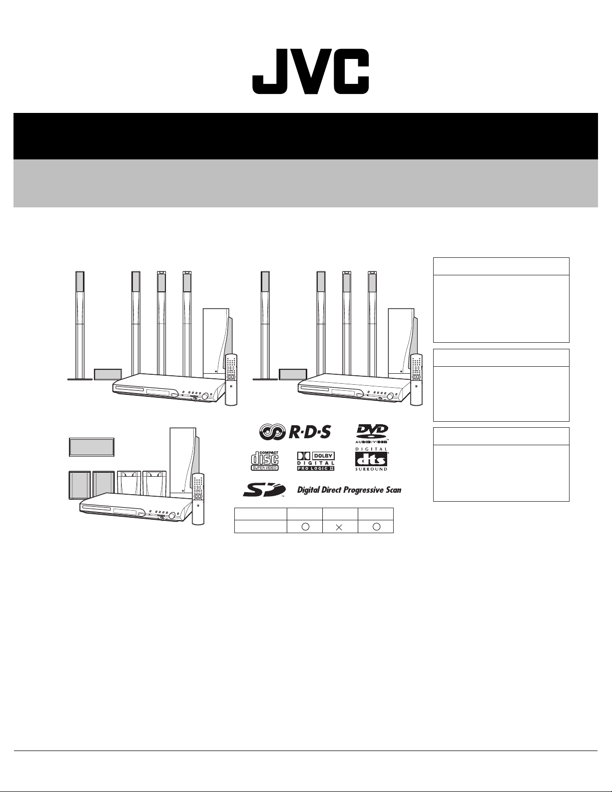
DVD DIGITAL CINEMA SYSTEM
MB23620046
TH-S9,TH-S8,TH-S7
SP-THS9F SP-THS9S
SP-THS9C
XV-THS9
SP-THS9C
SP-THS7F SP-TH7S
XV-THS7
SP-PWS7
SP-PWS9
SP-THS9F SP-THS9S
SP-THS9C
TH-S9
SD card
XV-THS8
TH-S8
TH-S7
SP-PWS8
TH-S9
Area suffix
B ------------------------------ U.K.
E ---------- Continental Europe
EN ----------- Northern Europe
EV ------------- Eastern Europe
TH-S8
Area suffix
B ------------------------------ U.K.
E ---------- Continental Europe
EN ----------- Northern Europe
TH-S7
Area suffix
E ---------- Continental Europe
EN ----------- Northern Europe
EV ------------- Eastern Europe
TABLE OF CONTENTS
1 PRECAUTION. . . . . . . . . . . . . . . . . . . . . . . . . . . . . . . . . . . . . . . . . . . . . . . . . . . . . . . . . . . . . . . . . . . . . . . . . 1-4
2 SPECIFIC SERVICE INSTRUCTIONS . . . . . . . . . . . . . . . . . . . . . . . . . . . . . . . . . . . . . . . . . . . . . . . . . . . . . . 1-8
3 DISASSEMBLY . . . . . . . . . . . . . . . . . . . . . . . . . . . . . . . . . . . . . . . . . . . . . . . . . . . . . . . . . . . . . . . . . . . . . . . 1-9
4 ADJUSTMENT . . . . . . . . . . . . . . . . . . . . . . . . . . . . . . . . . . . . . . . . . . . . . . . . . . . . . . . . . . . . . . . . . . . . . . . 1-26
5 TROUBLESHOOTING . . . . . . . . . . . . . . . . . . . . . . . . . . . . . . . . . . . . . . . . . . . . . . . . . . . . . . . . . . . . . . . . . 1-30
COPYRIGHT © 2004 Victor Company of Japan, Limited
No.MB236
2004/6
Page 2
SPECIFICATION
Center unit (XV-THS9/XV-THS7)
Audio section Total Harmonic Distortion*1 0.02%
Digital input*2 DIGITAL IN (OPTICAL) -21 dBm to -15 dBm (660 nm E30 nm)
Video section Video System PAL
Horizontal Resolution 500 lines
Signal-to-Noise Ratio
(Composite signal when "RGB" is selected)
Video output level Composite 1.0 V(p-p)/75 Ω
S-video-Y 1.0 V(p-p)/75 Ω
S-video-C 0.3 V(p-p)/75 Ω
Component-Y 1.0 V(p-p)/75 Ω
Component-PB/PR 0.7 V(p-p)/75 Ω
RGB 0.7 V(p-p)/75 Ω
Tuner section Tuning Range FM 87.50 MHz to 108.00 MHz
AM (MW) 522 kHz to 1 629 kHz
General Power Requirements AC 230 V , 50 Hz
Power Consumption 18 W (at operation) 2.0 W (in standby mode)
Dimensions (W × H × D) 435 mm × 58 mm × 319 mm
Mass 3.5 kg
64 dB
*1: This value is measured at System cord CONNECTOR for reference.
*2: Corresponding to Linear PCM, Dolby Digital, and DTS Digital Surround (with sampling frequency - 32 kHz, 44.1 kHz, 48 kHz)
Center unit (XV-THS8)
Audio section Total Harmonic Distortion*1 0.02%
Digital input*2 DIGITAL IN (OPTICAL) -21 dBm to -15 dBm (660 nm E30 nm)
Video section Video System PAL
Horizontal Resolution 500 lines
Signal-to-Noise Ratio
(Composite signal when "RGB" is selected)
Video output level Composite 1.0 V(p-p)/75 Ω
S-video-Y 1.0 V(p-p)/75 Ω
S-video-C 0.3 V(p-p)/75 Ω
Component-Y 1.0 V(p-p)/75 Ω
Component-PB/PR 0.7 V(p-p)/75 Ω
RGB 0.7 V(p-p)/75 Ω
Tuner section Tuning Range FM 87.50 MHz to 108.00 MHz
AM (MW) 522 kHz to 1 629 kHz
General Power Requirements AC 230 V , 50 Hz
Power Consumption 18 W (at operation) 2.0 W (in standby mode)
Dimensions (W × H × D) 435 mm × 57 mm × 319 mm
Mass 3.0 kg
64 dB
*1: This value is measured at System cord CONNECTOR for reference.
*2: Corresponding to Linear PCM, Dolby Digital, and DTS Digital Surround (with sampling frequency - 32 kHz, 44.1 kHz, 48 kHz)
1-2 (No.MB236)
Page 3
Subwoofer (SP-PWS9/SP-PWS7)
Amplifier section Front/Center/Surround 80 W per Ωhannel, RMS at 6 Ω (Center/Surround)/120 W per Ωhannel, RMS at 4 Ω
(Front) at 1 kHz, with 10 % total harmonic distortion.
Subwoofer 120 W, RMS at 4 Ω at 100 Hz, with 10 % total harmonic distortion.
Speaker section Speaker unit 16 cm Bass-reflex, Magnetically Shielded
Frequency Range 30 Hz to 200 Hz
General Power Requirements AC 230 V , 50 Hz
Power Consumption 110 W (at operation) 0 W (in standby mode)
Dimensions (W × H × D) 170 mm × 412 mm × 444 mm
Mass 12.0 kg
Subwoofer (SP-PWS8)
Amplifier section Front/Center/Surround 80 W per Ωhannel, RMS at 6 Ω (Center/Surround)/120 W per Ωhannel, RMS at 4 Ω
(Front) at 1 kHz, with 10 % total harmonic distortion.
Subwoofer 120 W, RMS at 4 Ω at 100 Hz, with 10 % total harmonic distortion.
Speaker section Speaker unit 16 cm Bass-reflex, Magnetically Shielded
Frequency Range 30 Hz to 200 Hz
General Power Requirements AC 230 V , 50 Hz
Power Consumption 110 W (at operation) 0 W (in standby mode)
Dimensions (W × H × D) 170 mm × 412 mm × 444 mm
Mass 12.0 kg
Satellite Speakers
Front speakers
(SP-THS9F)
Surround speakers
(SP-THS9S)
Center speaker
(SP-THS9C)
Designs & specifications are subject to change without notice.
Speakers 5.5 cm × 2, 3.0 cm Bass-reflex, Magnetically Shielded
Power Handling Capacity 120 W
Impedance 4 Ω
Frequency Range 95 Hz to 40 kHz
Dimensions (W × H × D) 250 mm × 1 103 mm × 250 mm
Mass 3.67 kg
Speakers 5.5 cm × 2 Bass-reflex, Magnetically Shielded
Power Handling Capacity 80 W
Impedance 6 Ω
Frequency Range 90 Hz to 30 kHz
Dimensions (W × H × D) 250 mm × 1 103 mm × 250 mm
Mass 3.77 kg
Speakers 5.5 cm × 2, 3.0 cm Bass-reflex, Magnetically Shielded
Power Handling Capacity 80 W
Impedance 6 Ω
Frequency Range 90 Hz to 40 kHz
Dimensions (W × H × D) 209 mm × 85 mm × 92 mm
Mass 0.87 kg
(No.MB236)1-3
Page 4
SECTION 1
PRECAUTION
1.1 Safety Precautions
(1) This design of this product contains special hardware and
many circuits and components specially for safety purposes. For continued protection, no changes should be made
to the original design unless authorized in writing by the
manufacturer. Replacement parts must be identical to
those used in the original circuits. Services should be performed by qualified personnel only.
(2) Alterations of the design or circuitry of the product should
not be made. Any design alterations of the product should
not be made. Any design alterations or additions will void
the manufacturers warranty and will further relieve the
manufacture of responsibility for personal injury or property
damage resulting therefrom.
(3) Many electrical and mechanical parts in the products have
special safety-related characteristics. These characteristics are often not evident from visual inspection nor can the
protection afforded by them necessarily be obtained by using replacement components rated for higher voltage, wattage, etc. Replacement parts which have these special
safety characteristics are identified in the Parts List of Service Manual. Electrical components having such features
are identified by shading on the schematics and by ( ) on
the Parts List in the Service Manual. The use of a substitute
replacement which does not have the same safety characteristics as the recommended replacement parts shown in
the Parts List of Service Manual may create shock, fire, or
other hazards.
(4) The leads in the products are routed and dressed with ties,
clamps, tubings, barriers and the like to be separated from
live parts, high temperature parts, moving parts and/or
sharp edges for the prevention of electric shock and fire
hazard. When service is required, the original lead routing
and dress should be observed, and it should be confirmed
that they have been returned to normal, after reassembling.
(5) Leakage shock hazard testing
After reassembling the product, always perform an isolation check on the exposed metal parts of the product (antenna terminals, knobs, metal cabinet, screw heads,
headphone jack, control shafts, etc.) to be sure the product
is safe to operate without danger of electrical shock.Do not
use a line isolation transformer during this check.
• Plug the AC line cord directly into the AC outlet. Using a
"Leakage Current Tester", measure the leakage current
from each exposed metal parts of the cabinet, particularly any exposed metal part having a return path to the
chassis, to a known good earth ground. Any leakage current must not exceed 0.5mA AC (r.m.s.).
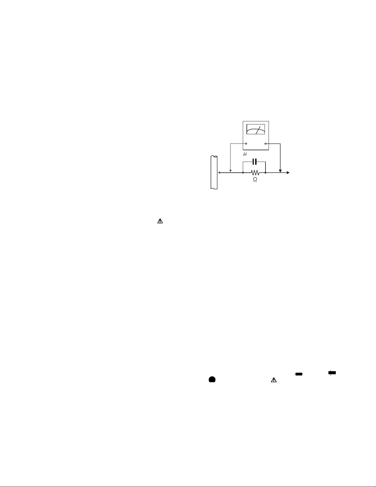
• Alternate check method
Plug the AC line cord directly into the AC outlet. Use an
AC voltmeter having, 1,000Ω per volt or more sensitivity
in the following manner. Connect a 1,500Ω 10W resistor
paralleled by a 0.15µF AC-type capacitor between an ex-
posed metal part and a known good earth ground.
Measure the AC voltage across the resistor with the AC
voltmeter.
Move the resistor connection to each exposed metal
part, particularly any exposed metal part having a return
path to the chassis, and measure the AC voltage across
the resistor. Now, reverse the plug in the AC outlet and
repeat each measurement. Voltage measured any must
not exceed 0.75 V AC (r.m.s.). This corresponds to 0.5
mA AC (r.m.s.).
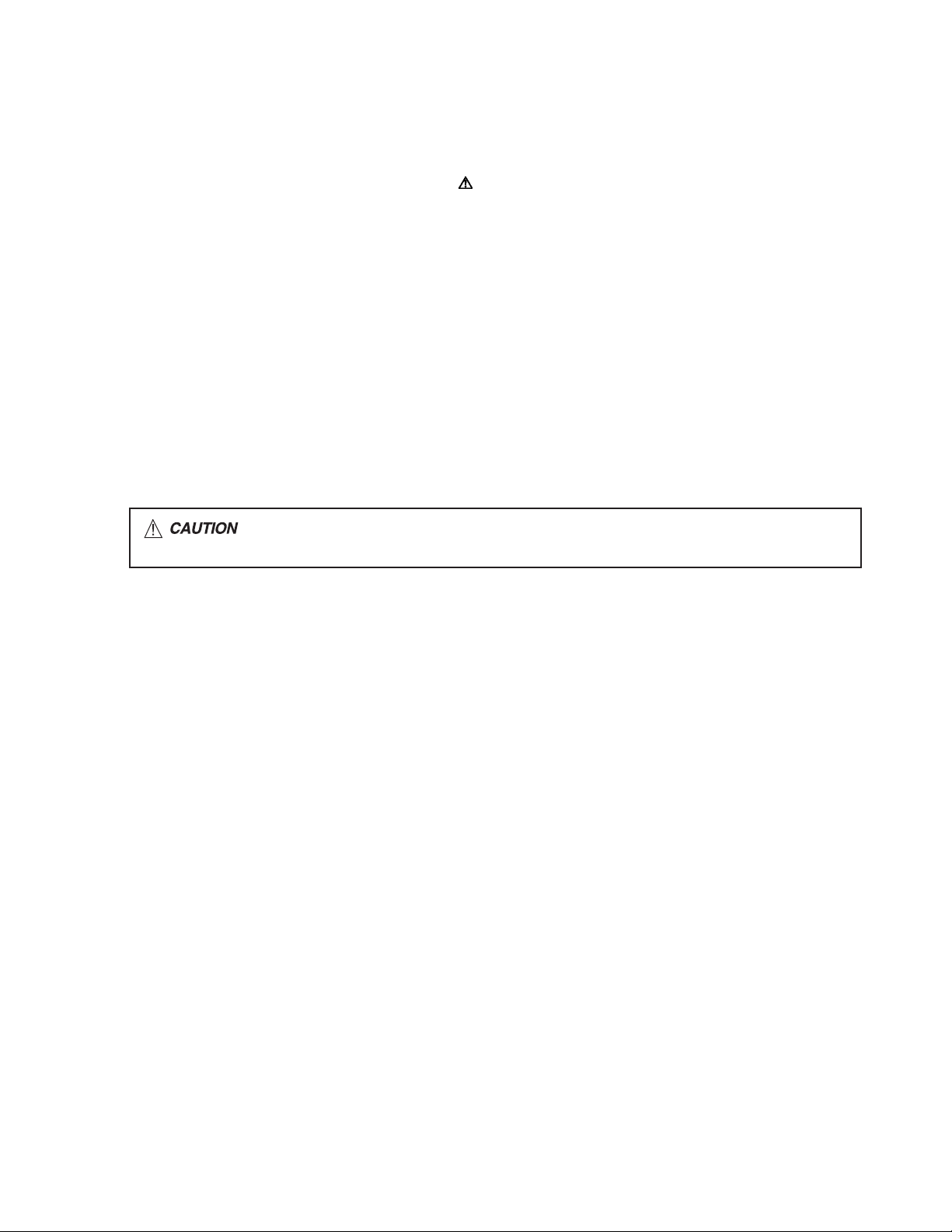
AC VOLTMETER
(Having 1000
ohms/volts,
or more sensitivity)
0.15 F AC TYPE
Place this
probe on
1500 10W
Good earth ground
1.2 Warning
(1) This equipment has been designed and manufactured to
meet international safety standards.
(2) It is the legal responsibility of the repairer to ensure that
these safety standards are maintained.
(3) Repairs must be made in accordance with the relevant
safety standards.
(4) It is essential that safety critical components are replaced
by approved parts.
(5) If mains voltage selector is provided, check setting for local
voltage.
1.3 Caution
Burrs formed during molding may be left over on some parts
of the chassis.
Therefore, pay attention to such burrs in the case of preforming repair of this system.
1.4 Critical parts for safety
In regard with component parts appearing on the silk-screen
printed side (parts side) of the PWB diagrams, the parts that are
printed over with black such as the resistor ( ), diode ( )
and ICP ( ) or identified by the " " mark nearby are critical
for safety. When replacing them, be sure to use the parts of the
same type and rating as specified by the manufacturer.
(This regulation dose not Except the J and C version)
each exposed
metal part.
1-4 (No.MB236)
Page 5
1.5 Safety Precautions (U.K only)
(1) This design of this product contains special hardware and many circuits and components specially for safety purposes. For con-
tinued protection, no changes should be made to the original design unless authorized in writing by the manufacturer. Replacement parts must be identical to those used in the original circuits.
(2) Any unauthorised design alterations or additions will void the manufacturer's guarantee; furthermore the manufacturer cannot
accept responsibility for personal injury or property damage resulting therefrom.
(3) Essential safety critical components are identified by ( ) on the Parts List and by shading on the schematics, and must never
be replaced by parts other than those listed in the manual. Please note however that many electrical and mechanical parts in
the product have special safety related characteristics. These characteristics are often not evident from visual inspection. Parts
other than specified by the manufacturer may not have the same safety characteristics as the recommended replacement parts
shown in the Parts List of the Service Manual and may create shock, fire, or other hazards.
(4) The leads in the products are routed and dressed with ties, clamps, tubings, barriers and the like to be separated from live parts,
high temperature parts, moving parts and/or sharp edges for the prevention of electric shock and fire hazard. When service is
required, the original lead routing and dress should be observed, and it should be confirmed that they have been returned to
normal, after re-assembling.
1.5.1 Warning
(1) Service should be performed by qualified personnel only.
(2) This equipment has been designed and manufactured to meet international safety standards.
(3) It is the legal responsibility of the repairer to ensure that these safety standards are maintained.
(4) Repairs must be made in accordance with the relevant safety standards.
(5) It is essential that safety critical components are replaced by approved parts.
(6) If mains voltage selector is provided, check setting for local voltage.
Burrs formed during molding may be left over on some parts of the chassis. Therefore,
pay attention to such burrs in the case of preforming repair of this system.
(No.MB236)1-5
Page 6
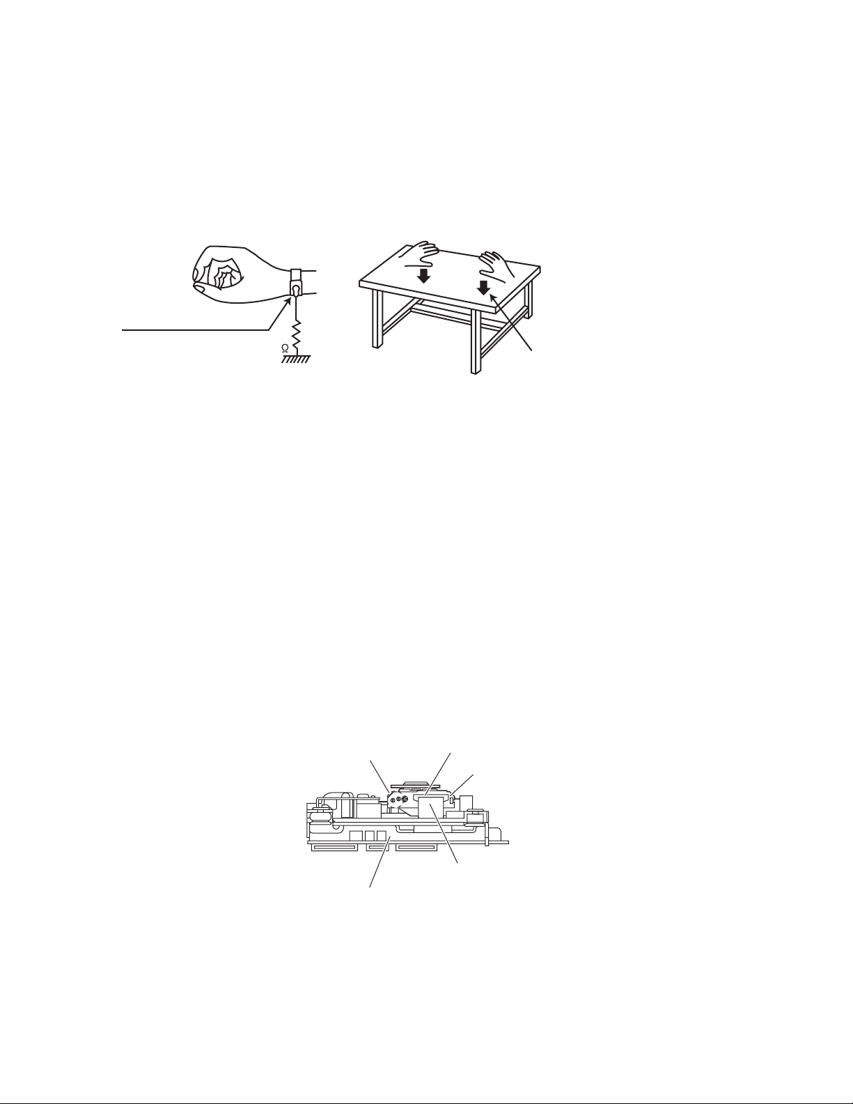
1.6 Preventing static electricity
Electrostatic discharge (ESD), which occurs when static electricity stored in the body, fabric, etc. is discharged, can destroy the laser
diode in the traverse unit (optical pickup). Take care to prevent this when performing repairs.
1.6.1 Grounding to prevent damage by static electricity
Static electricity in the work area can destroy the optical pickup (laser diode) in devices such as laser products.
Be careful to use proper grounding in the area where repairs are being performed.
(1) Ground the workbench
Ground the workbench by laying conductive material (such as a conductive sheet) or an iron plate over it before placing the
traverse unit (optical pickup) on it.
(2) Ground yourself
Use an anti-static wrist strap to release any static electricity built up in your body.
(caption)
Anti-static wrist strap
1M
Conductive material
(conductive sheet) or iron palate
(3) Handling the optical pickup
• In order to maintain quality during transport and before installation, both sides of the laser diode on the replacement optical
pickup are shorted. After replacement, return the shorted parts to their original condition.
(Refer to the text.)
• Do not use a tester to check the condition of the laser diode in the optical pickup. The tester's internal power source can easily
destroy the laser diode.
1.7 Handling the traverse unit (optical pickup)
(1) Do not subject the traverse unit (optical pickup) to strong shocks, as it is a sensitive, complex unit.
(2) Cut off the shorted part of the flexible cable using nippers, etc. after replacing the optical pickup. For specific details, refer to the
replacement procedure in the text. Remove the anti-static pin when replacing the traverse unit. Be careful not to take too long a
time when attaching it to the connector.
(3) Handle the flexible cable carefully as it may break when subjected to strong force.
(4) I t is not possible to adjust the semi-fixed resistor that adjusts the laser power. Do not turn it.
1.8 Attention when traverse unit is decomposed
*Please refer to "Disassembly method" in the text for the pickup unit.
• Apply solder to the short land sections before the flexible wire is disconnected from the connecto on the servo board. (If the flexible
wire is disconnected without applying solder, the pickup may be destroyed by static electricity.)
• In the assembly, be sure to remove solder from the short land sections after connecting the flexible wire.
Short land section
Connector
Pickup
1-6 (No.MB236)
Card wire
Traverse mechanism assembly
Page 7
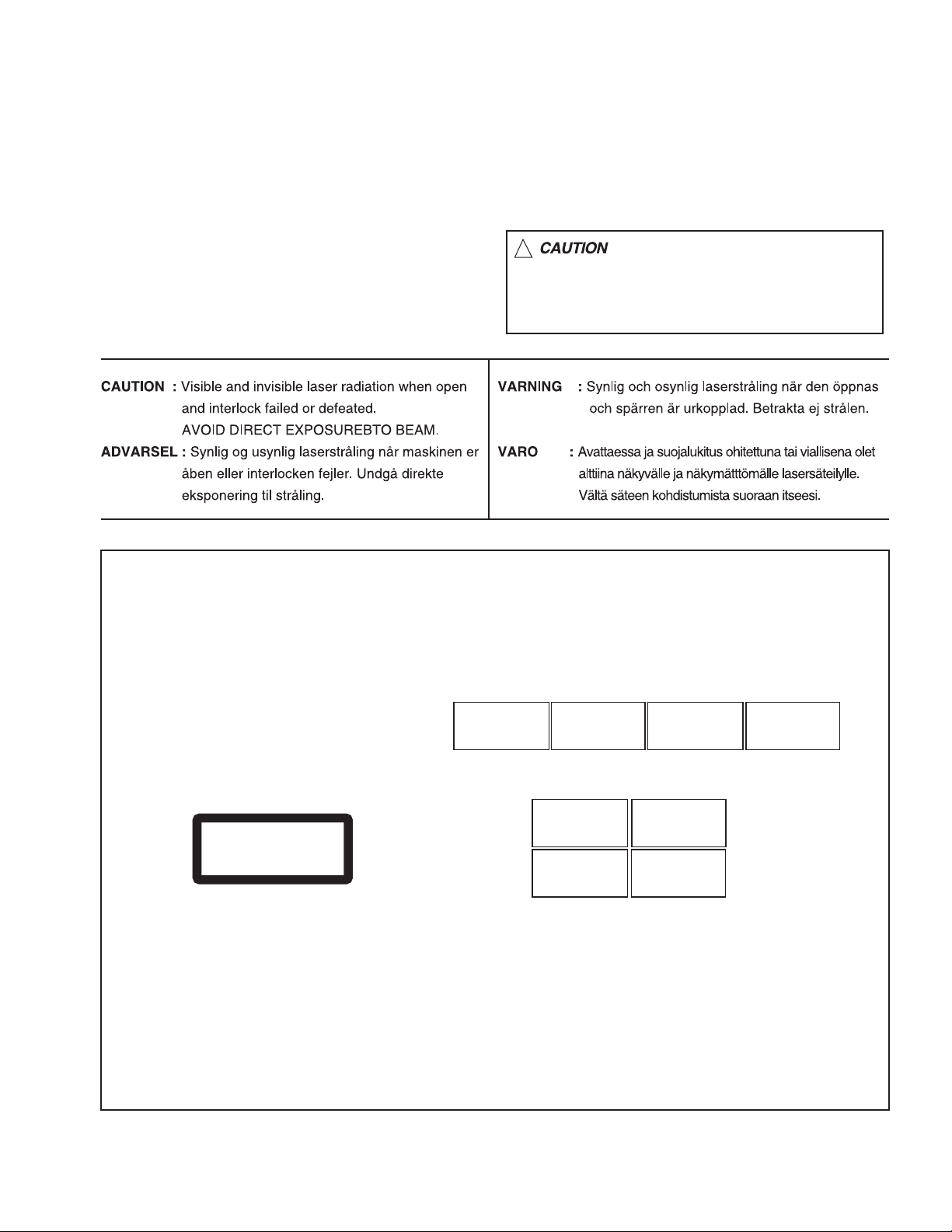
1.9 Important for laser products
!
1.CLASS 1 LASER PRODUCT
2.DANGER : Invisible laser radiation when open and inter
lock failed or defeated. Avoid direct exposure to beam.
3.CAUTION : There are no serviceable parts inside the
Laser Unit. Do not disassemble the Laser Unit. Replace
the complete Laser Unit if it malfunctions.
4.CAUTION : The CD,MD and DVD player uses invisible
laser radiation and is equipped with safety switches which
prevent emission of radiation when the drawer is open and
the safety interlocks have failed or are defeated. It is
dangerous to defeat the safety switches.
5.CAUTION : If safety switches malfunction, the laser is able
to function.
6.CAUTION : Use of controls, adjustments or performance of
procedures other than those specified here in may result in
hazardous radiation exposure.
Please use enough caution not to
see the beam directly or touch it
in case of an adjustment or operation
check.
REPRODUCTION AND POSITION OF LABELS
WARNING LABEL
CAUTION : Visible and Invisible
laser radiation when open and
interlock failed or defeated.
AVOID DIRECT EXPOSURE TO
BEAM. (e)
CLASS 1
LASER PRODUCT
ADVARSEL : Synlig og usynlig
laserstråling når maskinen er
åben eller interlocken fejeler.
Undgå direkte eksponering til
stråling. (d)
CAUTION : Visible and Invisible
laser radiation when open and
interlock failed or defeated.
AVOID DIRECT EXPOSURE TO
BEAM. (e)
VARNING : Synlig och
osynling laserstrålning när
den öppnas och spärren är
urkopplad. Betrakta ej
strålen. (s)
VARNING : Synlig och
osynling laserstrålning när
den öppnas och spärren är
urkopplad. Betrakta ej
strålen. (s)
VARO : Avattaessa ja suojalukitus
ohitettuna tai viallisena olet alttiina
näkyvälle ja näkymättömälle
lasersäteilylle. Vältä säteen
kohdistumista suoraan itseesi. (f)
ADVARSEL : Synlig og usynlig
laserstråling når maskinen er
åben eller interlocken fejeler.
Undgå direkte eksponering til
stråling. (d)
VARO : Avattaessa ja suojalukitus
ohitettuna tai viallisena olet alttiina
näkyvälle ja näkymättömälle
lasersäteilylle. Vältä säteen
kohdistumista suoraan itseesi. (f)
(No.MB236)1-7
Page 8

SECTION 2
SPECIFIC SERVICE INSTRUCTIONS
This service manual does not describe SPECIFIC SERVICE INSTRUCTIONS.
1-8 (No.MB236)
Page 9
SECTION 3
DISASSEMBLY
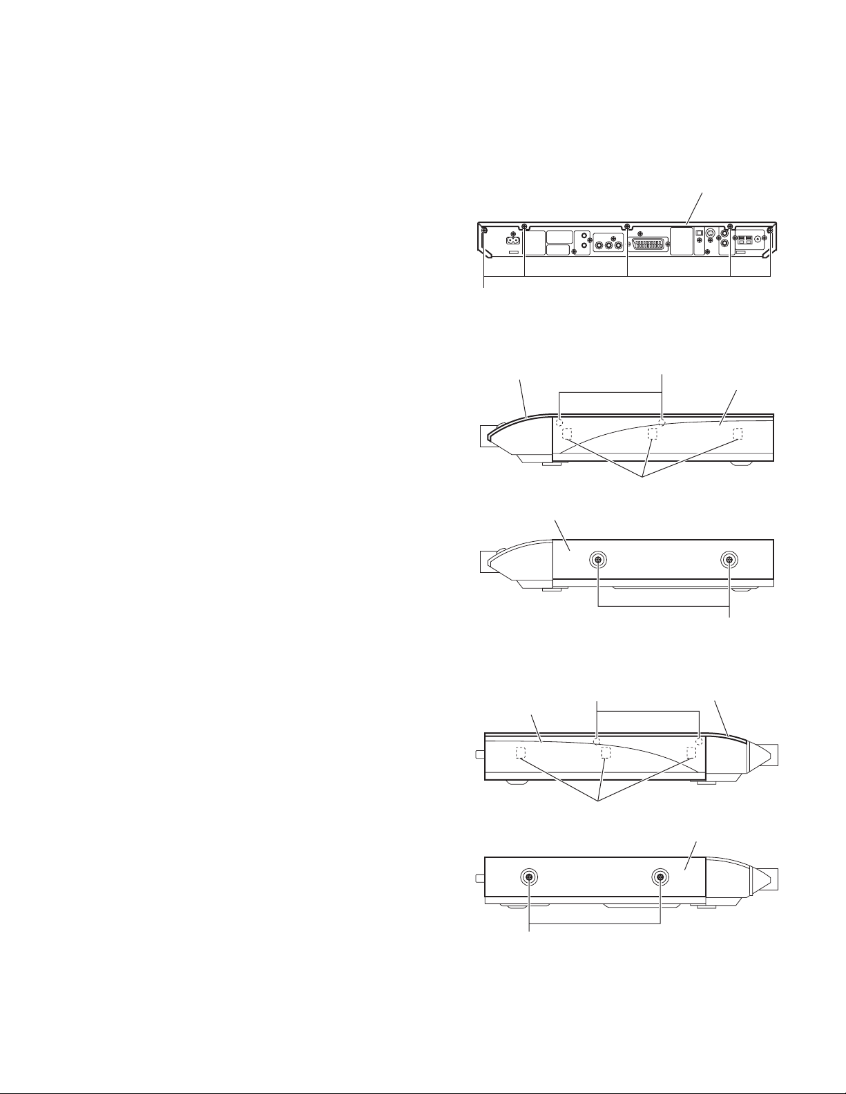
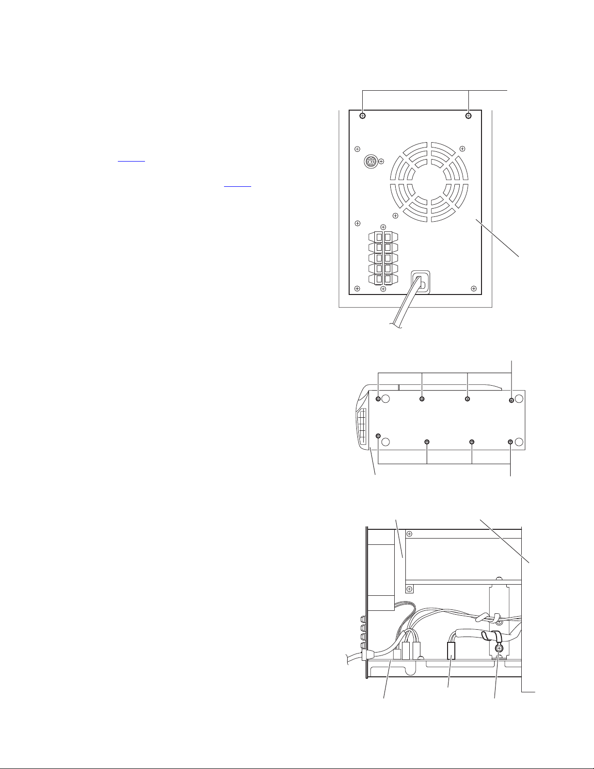
3.1 Main body section
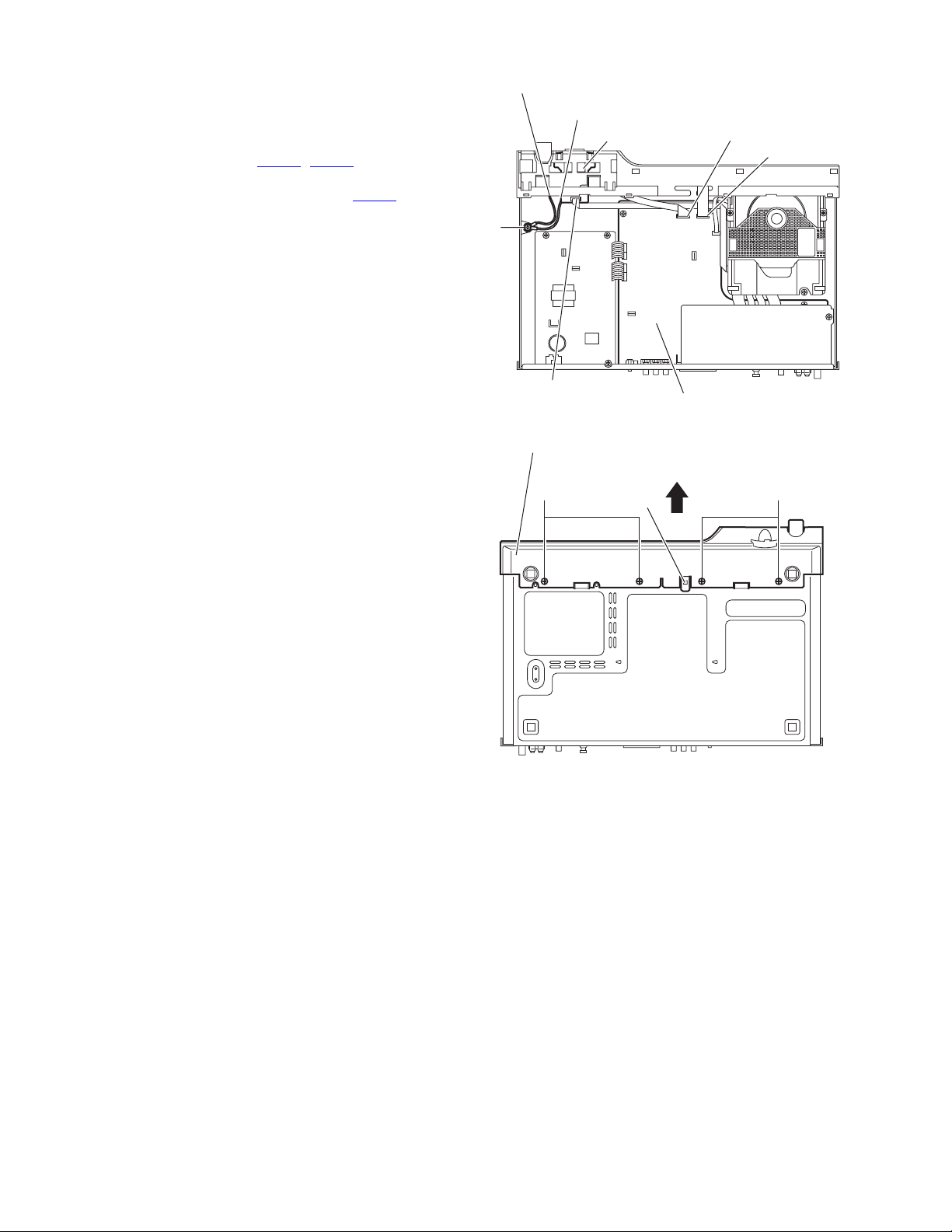
3.1.1 Removing the top cover assembly
(See Figs.1 to 3) [For XV-THS9 and XV-THS7 models]
(1) From the back side of the main body, remove the five
screws A attaching the top cover assembly. (See Fig.1)
(2) From the both sides of the main body, release the engage-
ment sections a to remove the side panels (L)/(R) from the
main body in the direction of the arrow. (See Figs.2 and 3.)
(3) Remove the four screws B attaching the top cover assem-
bly. (See Figs.2 and 3.)
(4) Lift the rear section of the top cover assembly upward and
remove the top cover assembly from the main body. (See
Figs.2 and 3.)
3.1.2 Removing the metal cover
(See Figs.1 to 3) [For XV-THS8 model]
(1) From the back side of the main body, remove the three
screws A attaching the metal cover. (See Fig.1)
(2) From the both sides of the main body, remove the four
screws B attaching the metal cover. (See Figs.2 and 3)
(3) Lift the rear section of the metal cover upward while ex-
tending the lower sections of the metal cover. (See Figs.2
and 33.)
A
[XV-THS9, XV-THS7]
Top cover assembly
[XV-THS8]
Metal cover
Top cover assembly
Fig.1
B
Side panel (R)
a
[XV-THS9, XV-THS7]
Side panel (L)
[XV-THS8]
B
B
B
Fig.2
Top cover assembly
a
Metal cover
Fig.3
(No.MB236)1-9
Page 10
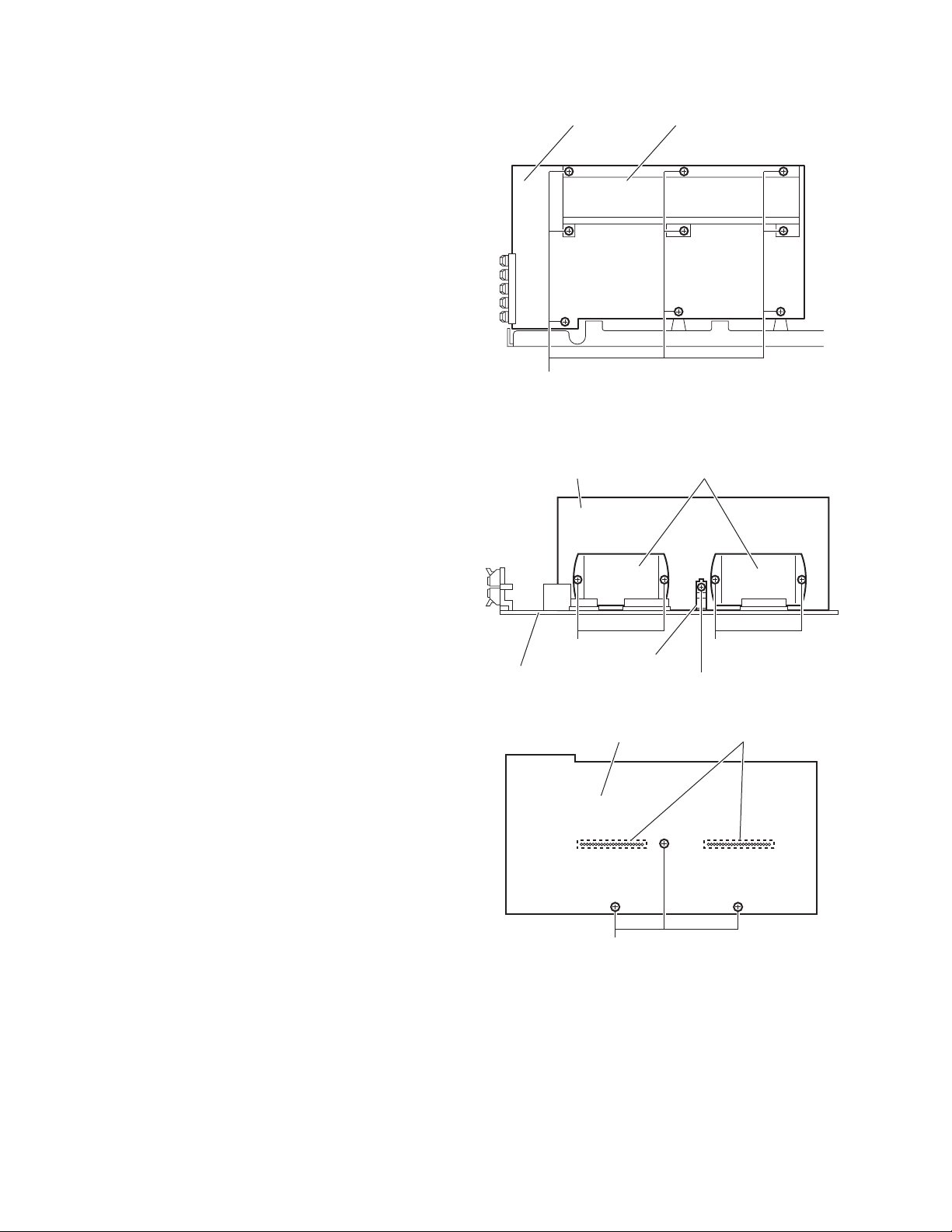
3.1.3 Removing the front panel assembly
(See Figs.4 and 5)
• Prior to performing the following procedures, remove the top
cover assembly or metal cover.
(1) From the top side of the main body, disconnect the card
wires from the connectors (CN451
board. (See Fig.4)
(2) Disconnect the card wire from the connector CN802
SD card board. [For XV-THS9 and XV-THS7 models]
(See Fig.4.)
(3) Remove the screw C attaching the earth wires to the main
board. (See Fig.4)
Reference:
When attaching the screw C, attach the earth wires with
it. (See Fig.4)
(4) From the bottom side of the main body, remove the four
screws D attaching the front panel assembly. (See Fig.5)
(5) Remove the front panel assembly in the direction of the ar-
row while releasing the joint b. (See Fig.5)
, CN452) on the main
on the
Earth wire
Earth wire [TH-S9,TH-S7]
C
CN802
Front panel assembly
SD board
CN452
CN451
Main board
Fig.4
D D
b
Fig.5
1-10 (No.MB236)
Page 11
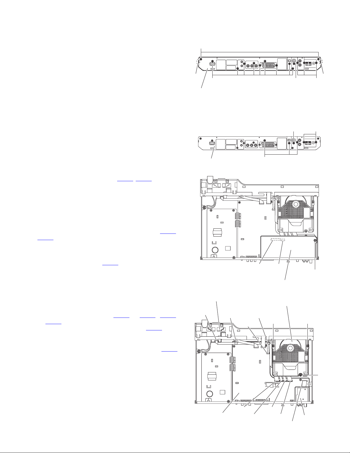
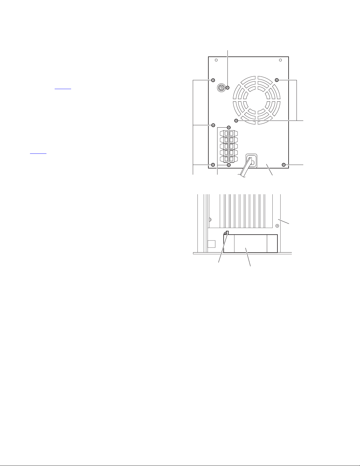
3.1.4 Removing the rear panel
(See Fig.6)
• Prior to performing the following procedures, remove the top
cover assembly or metal cover.
(1) From the back side of the main body, remove the twelve
screws E and screw F attaching the rear panel. [For XV-
THS9 and XV-THS7 models]
(2) From the back side of the main body, remove the fourteen
screws E and screw F attaching the rear panel. [For XV-
THS8 model]
(3) Release the engagement sections c and remove the rear
panel from the main body.
3.1.5 Removing the audio signal I/O board
(See Figs.7 and 8)
• Prior to performing the following procedures, remove the top
cover assembly or metal cover.
(1) From the back side of the main body, remove the screw G
and three screws H attaching the audio signal I/O board to
the rear panel. (See Fig.7)
(2) From the top side of the main body, remove the screw J at-
taching the audio signal I/O board to the chassis base.
(See Fig.8)
(3) Turn over the audio signal I/O board and disconnect the
card wires from the connectors (CN441
ward side of the audio signal I/O board. (See Fig.8)
, CN442) on the for-
[XV-THS8]
E
c
E F
Rear panel
Fig.6
Rear panel
Fig.7
H
G
c
E
K
3.1.6 Removing the tuner
(See Figs.7 to 9)
• Prior to performing the following procedures, remove the top
cover assembly or metal cover and audio signal I/O board.
Reference:
Disconnect the card wires from the connectors (CN441
CN442) on the audio signal I/O board as required. (See Fig.8.)
(1) From the back side of the main body, remove the two
screws K attaching the tuner to the rear panel. (See Fig.7)
(2) From the top side of the main body, disconnect the card
wire from the connector CN410
Fig.9)
(3) Take out the tuner from the main body.
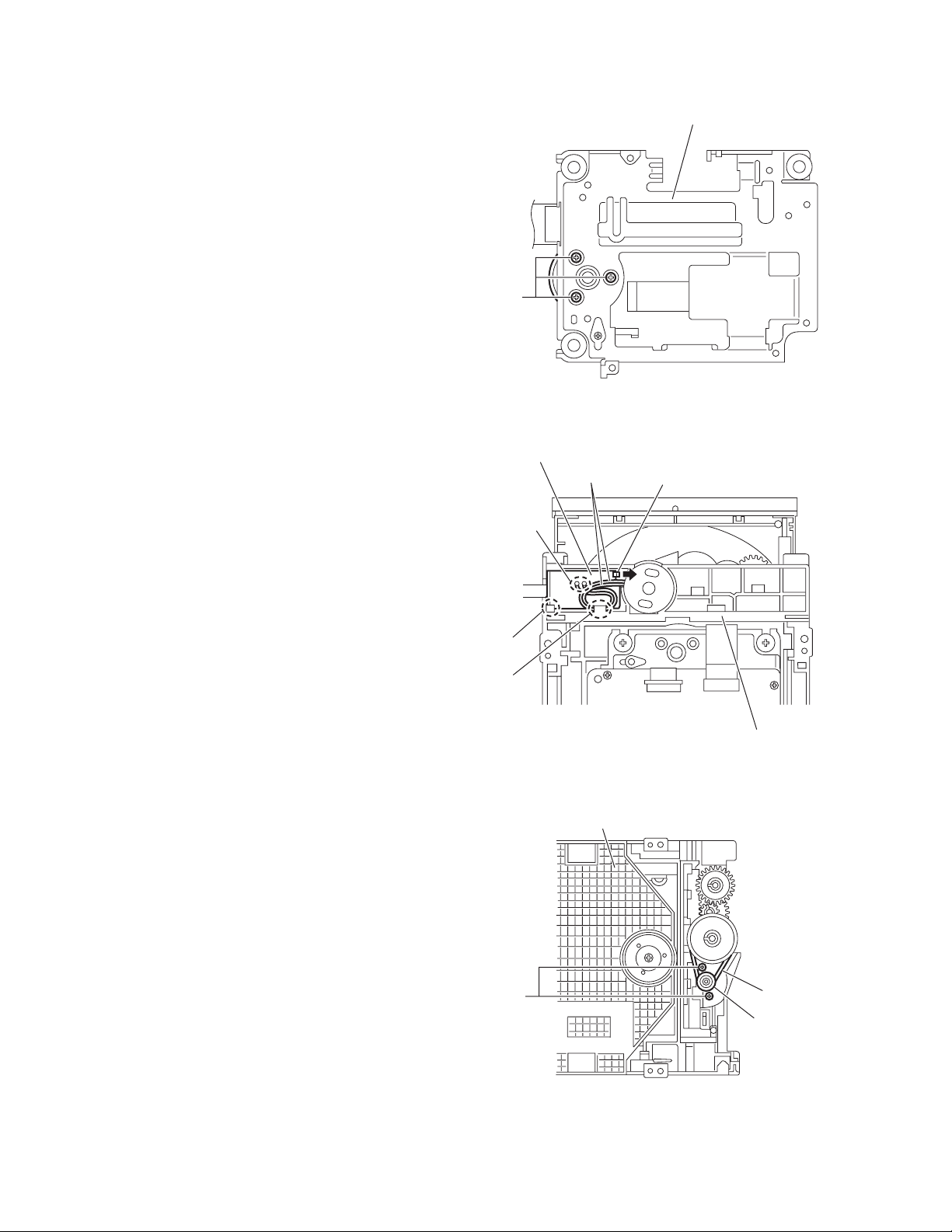
3.1.7 Removing the DVD mechanism assembly
(See Fig.9)
• Prior to performing the following procedures, remove the top
cover assembly or metal cover and audio signal I/O board.
(1) From the top side of the main body, disconnect the card
wires from the connectors (CN401
CN409
) on the main board.
(2) Disconnect the card wire from the connector CN802 on the
SD card board. [For TH-S9 and TH-S7 models]
Reference:
After connecting the card wire to the connector CN802
on the SD card board, fix the card wire with the spacers
as before.
(3) Remove the three screws L attaching the DVD mechanism
assembly on the main body.
(4) Take out the DVD mechanism assembly from the main
body.
on the main board. (See
to CN403, CN408,
,
CN441
CN442
J
Audio signal input/output board
Fig.8
SD board
CN802
Spacer
CN408
DVD mechanism assembly
Spacer
L L
L
Main board
CN401 CN403
CN409 CN402
Fig.9
Tuner
CN410
(No.MB236)1-11
Page 12
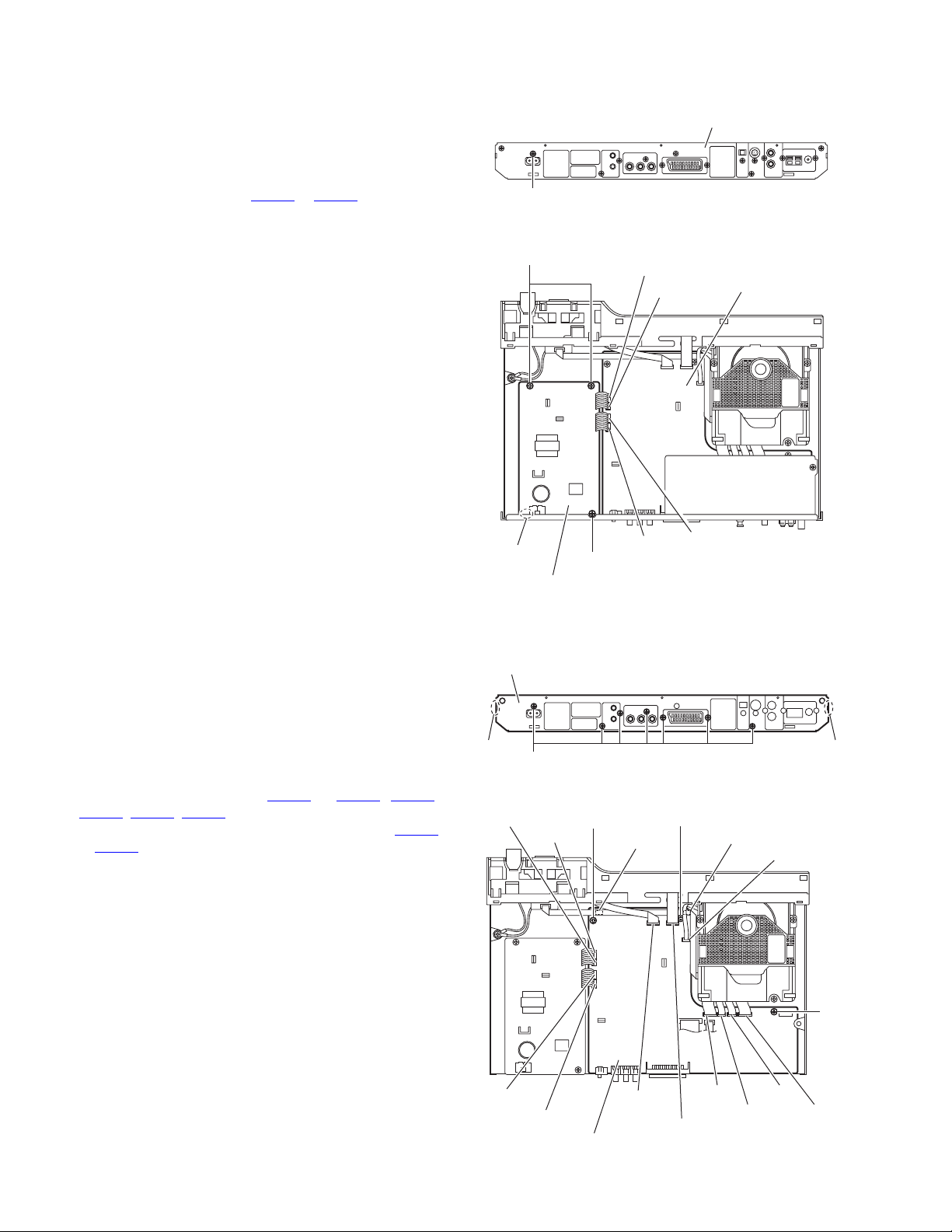
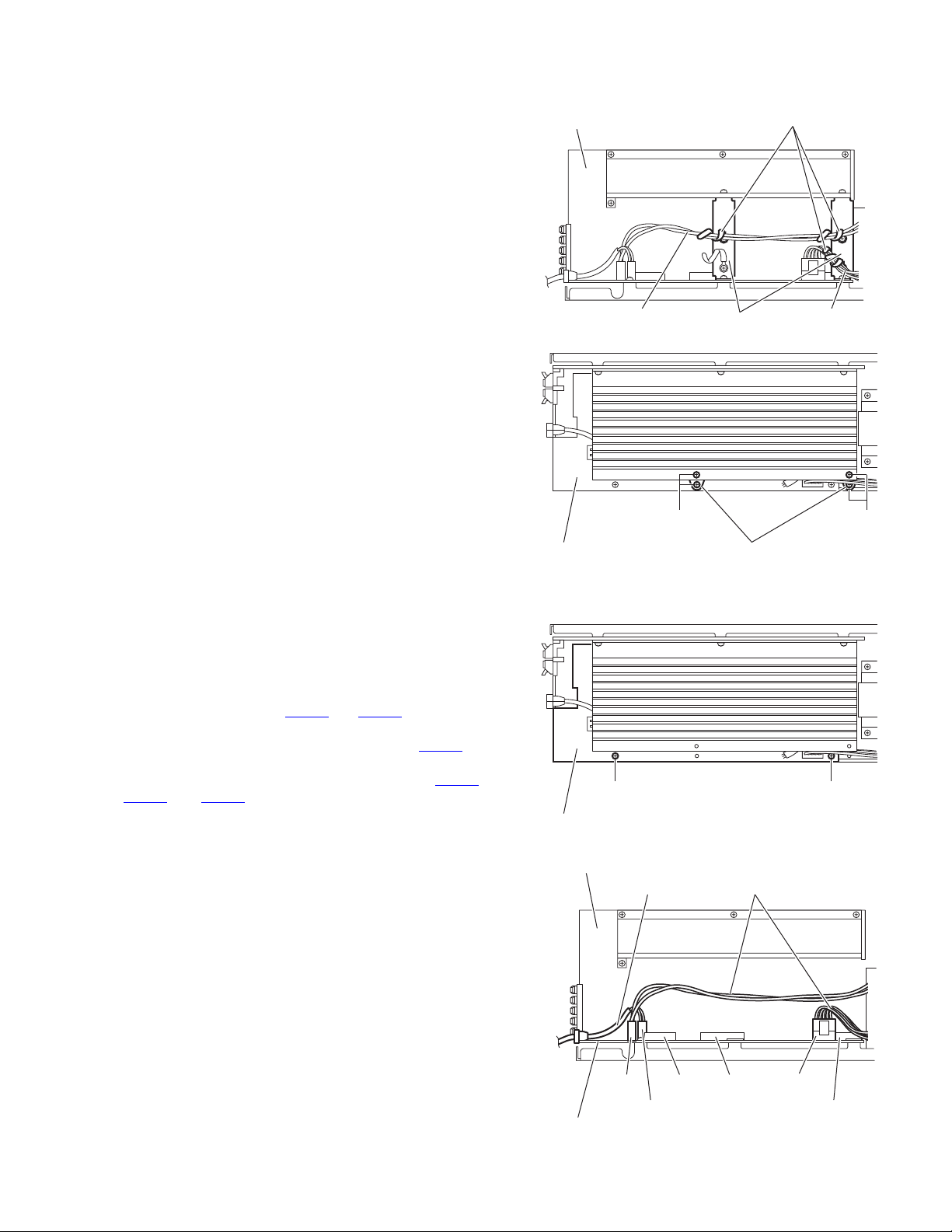
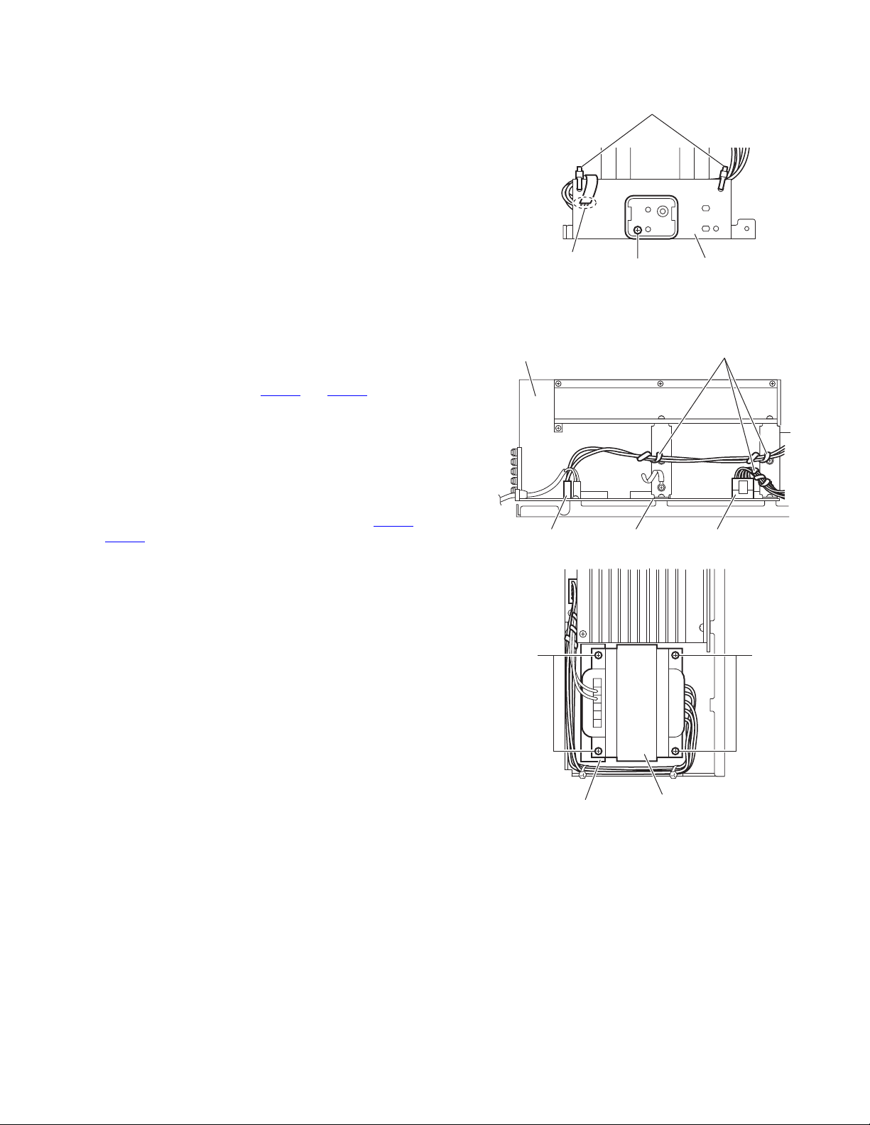
3.1.8 Removing the power board
(See Figs.10 and 11)
• Prior to performing the following procedures, remove the top
cover assembly or metal cover.
(1) From the back side of the main body, remove the screw M
attaching the power board to the rear panel. (See Fig.10)
(2) From the top side of the main body, disconnect the parallel
wires from the connectors (CN404
board. (See Fig.11)
(3) Remove the three screws N attaching the power board.
(See Fig.11)
(4) Take out the power board from the main body.
Reference:
When attaching the power board on the chassis base, align the
projection d of the chassis base in the hole of the power board.
(See Fig.11.)
to CN407) on the main
M
N
Fig.10
CN407
CN406
Rear panel
Main board
3.1.9 Removing the main board
(See Figs.12 and 13)
• Prior to performing the following procedures, remove the top
cover assembly or metal cover, audio signal I/O board and tuner.
(1) From the back side of the main body, remove the seven
screws P attaching the rear panel. (See Fig.12.)
(2) Release the engagement sections e and remove the rear
panel from the main body. (See Fig.12.)
(3) From the top side of the main body, disconnect the card
wires from the connectors (CN401
CN409, CN451, CN452) on the main board. (See Fig.13.)
(4) Disconnect the parallel wires from the connectors CN404
to CN407 on the main board. (See Fig.13.)
(5) Remove the spacers fixing the card wires on the main
board. [For XV-THS9, XV-THS7 models] (See Fig.13.)
Reference:
After attaching the main board, fix the card wire with the
spacers as before.
(6) Remove the three screws Q attaching the main board on
the main body.
(7) Take out the main board from the main body.
to CN403, CN408,
d
Power board
Rear panel
e
P
CN406
CN407
CN404 CN405
N
P
Spacer
Fig.11
e
Fig.12
P
Spacer
CN408
P
1-12 (No.MB236)
CN405
CN404
CN452
Main board
CN451
Fig.13
CN401
CN403
CN409 CN402
Page 13
3.1.10 Removing the FL board
(See Fig.14)
• Prior to performing the following procedures, remove the top
cover assembly or metal cover and front panel assembly.
(1) From the inside of the front panel assembly, remove the
screw R attaching the FL board.
(2) Take out the FL board from the front panel assembly.
Reference:
• When attaching the FL board, align the section f of the front
panel assembly to the right side of the FL board.
• After attaching the FL board, passing the card wire through
the section g.
3.1.11 Removing the key board
(See Figs.15 to 16)
• Prior to performing the following procedures, remove the top
cover assembly or metal cover, front panel assembly and FL
board.
• It is not necessary to remove the FL board. [For XV-THS9 and
XV-THS7 models]
(1) From the front side of the front panel assembly, pull the vol-
ume knob out of the front panel assembly in the direction of
the arrow. (See Fig.15.)
(2) From the inside of the front panel assembly, release the
seven claws h attaching the front cover assembly. [For XV-
THS8 model] (See Fig.16.)
(3) Remove the front cover assembly in the direction of the ar-
row. [For XV-THS8 model] (See Fig.16.)
(4) Remove the three screws S attaching the key board and
take out the key board from the front panel assembly. (See
Fig.16.)
FL board
R
Volume knob
[XV-THS9, XV-THS7]
Key board
g
f
Fig.14
Front panel assembly
Fig.15
3.1.12 Removing the SD card board
(See Fig.17) [For XV-THS9 and XV-THS7 model]
• Prior to performing the following procedures, remove the top
cover assembly or metal cover, front panel assembly and key
board.
From the top side of the front panel assembly, remove the SD
card board in the direction of the arrow while releasing the sections i of the front panel assembly.
S
[XV-THS8]
S
Front panel assembly
h
Key board Front cover
Fig.16
i
Fig.17
SD board
(No.MB236)1-13
Page 14
3.2 DVD mechanism section
• Prior to performing the following procedures, remove the DVD mechanism assembly from the main body.
(See "3.1.7 Removing the DVD mechanism assembly".)
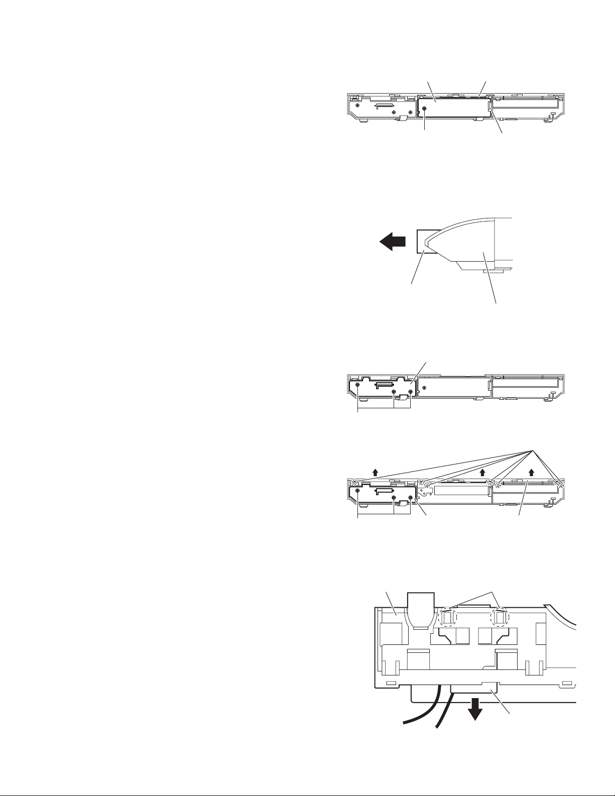
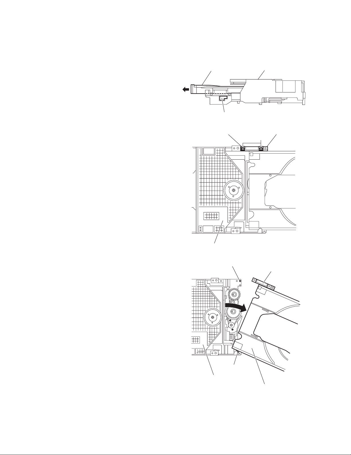
3.2.1 Removing the tray assembly
(See Figs.1 to 3)
(1) From the right side of the DVD mechanism assembly, push
the slide cam and pull the tray assembly out of the DVD
mechanism assembly in the direction of the arrow. (See
Fig.1.)
(2) From the top side of the DVD mechanism assembly, re-
move the two screws A attaching the leaf spring to the
bushing and remove the leaf spring. (See Fig.2.)
(3) Remove the bushing of the tray assembly from the projec-
tion a on the DVD mechanism assembly and move the tray
assembly in the direction of the arrow. (See Fig.3.)
(4) Remove the claw b of the tray assembly from the DVD
mechanism assembly and take out the tray assembly. (See
Fig.3.)
Tray assembly
Slide cam
Leaf spring
DVD mechanism assembly
Fig.1
Bushing
A
DVD mechanism assembly
Fig.2
Projection a
Claw b
DVD mechanism assembly
Fig.3
Bushing
Tray assembly
1-14 (No.MB236)
Page 15
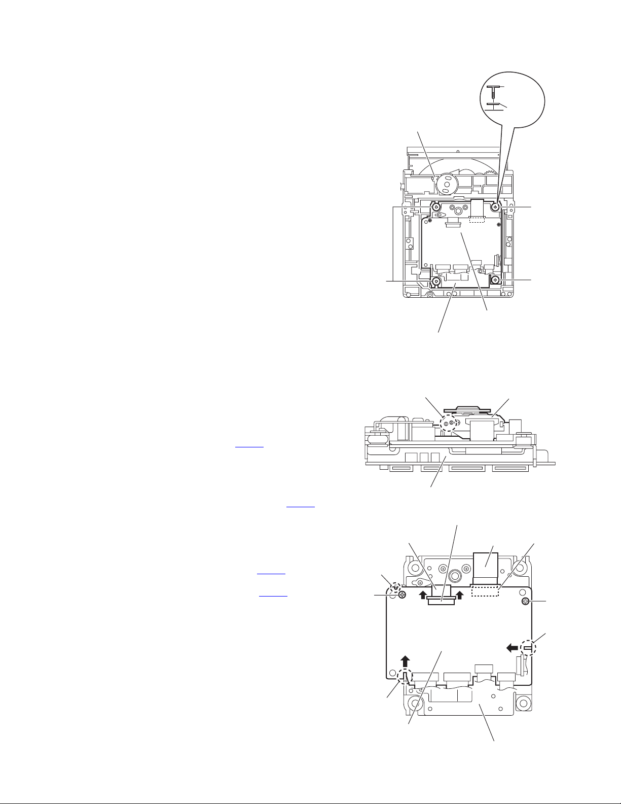
3.2.2 Removing the traverse mechanism assembly
(See Figs.4)
From the bottom side of the DVD mechanism assembly, remove
the three screws B and screw B’ attaching the traverse mechanism assembly and take out the DVD traverse mechanism assembly with the DVD servo board.
Reference:
When attaching the screw B’, attach the washer with it.
B'
Washer
DVD mechanism assembly
B'
3.2.3 Removing the DVD servo board
(See Figs.5 and 6)
• Prior to performing the following procedures, remove the
traverse mechanism assembly.
(1) From the side of the traverse mechanism assembly, solder
the short land sections c on the pickup. (See Fig.5.)
(2) From the bottom side of the traverse mechanism assem-
bly, release the lock of the connector CN101
servo board in the direction of the arrow 1 and disconnect
the card wire. (See Fig.6.)
Caution:
• Solder the short land sections c on the pickup before
disconnecting the card wire from the connector CN101
on the DVD servo board. If the card wire is disconnected without attaching solder, the pickup may be destroyed by static electricity. (See Figs.5 and 6.)
• When attaching the DVD servo board, be sure to remove solders from the short land sections c after connecting the card wire to the connector CN101
DVD servo board. (See Figs.5 and 6.)
(3) Disconnect the card wire from the connector CN201
DVD servo board. (See Fig.6.)
(4) Remove the two screws C attaching the DVD servo board.
(See Fig.6.)
(5) Remove the DVD servo board from the engagement sec-
tion d in an upward and remove the engagement section f
in the direction 3 while removing the engagement section e
in the direction of the arrow 2. (See Fig.6.)
on the DVD
on the
on the
B
DVD servo board
Traverse mechanism assembly
Fig.4
Short land section c
Traverse mechanism assembly
Fig.5
CN101
Card wire
d
C
1
2
1
Card wire
B
Pickup
CN201
C
f
3
e
DVD servo board
Traverse mechanism assembly
Fig.6
(No.MB236)1-15
Page 16
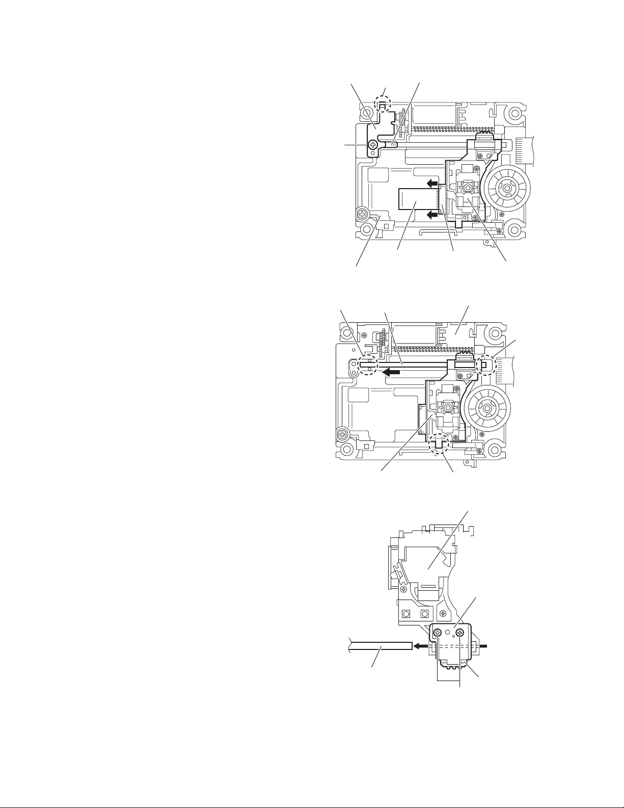
3.2.4 Removing the pickup
(See Figs.5, 7 to 9)
• Prior to performing the following procedures, remove the
traverse mechanism assembly.
(1) From the side of the traverse mechanism assembly, solder
the short land sections c on the pickup. (See Fig.5.)
(2) Release the lock of the connector on the pickup in the di-
rection of the arrow and disconnect the card wire. (See
Fig.7.)
Caution:
• Solder the short land sections c on the pickup before
disconnecting the card wire from the connector on the
pickup. If the card wire is disconnected without attaching solder, the pickup may be destroyed by static electricity. (See Figs.5 and 7.)
• When attaching the pickup, be sure to remove solders
from the short land sections c after connecting the
card wire to the connector on the pickup. (See Figs.5
and 7.)
(3) Remove the screw D attaching the plate and thrust spring.
(See Fig.7.)
(4) Remove the engagement section g attaching the plate to
the feed holder and remove the plate with the thrust spring.
(See Fig.7.)
(5) Remove the shaft of the pickup from the section h on the
traverse mechanism assembly and remove the shaft from
the section i while moving it in the direction of the arrow.
(See Fig.8.)
(6) Remove the pickup from the section j of the traverse mech-
anism assembly and take out the pickup with the shaft.
(See fig.8.)
(7) From the bottom side of the pickup, remove the two screws
E attaching the SW actuator and LEAD spring. (See Fig.9.)
(8) Pull the shaft out of the pickup. (See Fig.9.)
Plate
D
Card wire
Feed holder
h
Shaft
Thrust spring
g
Connector
Fig.7
Traverse mechanism assembly
Pickup
i
Pickup
Shaft
j
Fig.8
Pickup
SW actuator
LEAD spring
E
Fig.9
1-16 (No.MB236)
Page 17
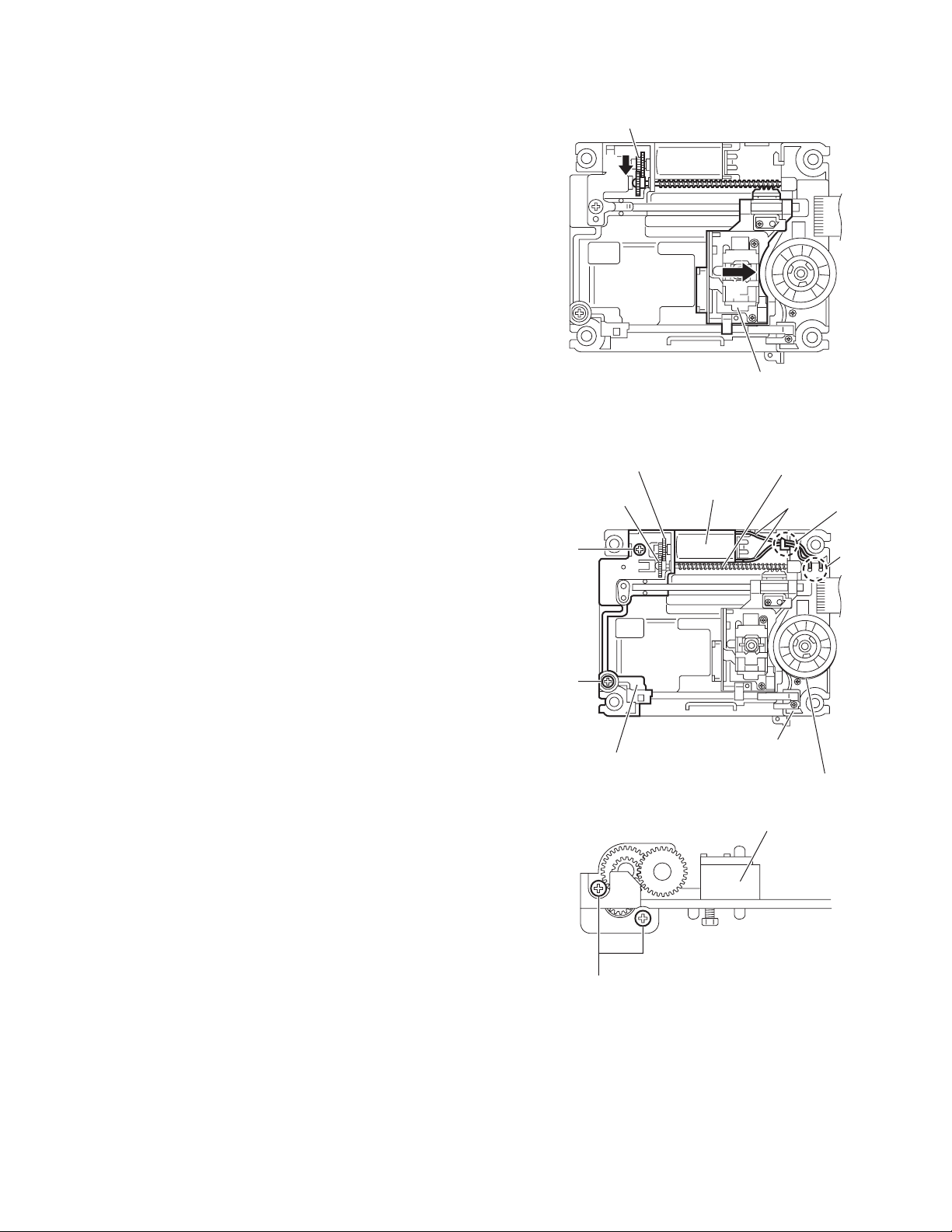
3.2.5 Attaching the pickup
(See Figs.5, 7 to 10)
• See "3.2.4 Removing the pickup".
(1) Attach the shaft, SW actuator and LEAD spring to the pick-
up. (See Fig.9.)
(2) Align the pickup to the section j of the traverse mechanism
assembly first, and set the both ends of the shaft of the
pickup in the sections g and i of the traverse mechanism
assembly. (See Fig.8.)
(3) Attach the plate and thrust spring. (See Fig.7.)
(4) Remove solders from the short land sections c after con-
necting the card wire to the connector on the pickup. (See
Figs.5 and 7.)
(5) Turn the feed gear M in the direction of the arrow 1 to move
the pickup in the direction of the arrow 2. (See Fig.10.)
3.2.6 Removing the feed motor
(See Figs.7,11 and 12)
• Prior to performing the following procedures, remove the
traverse mechanism assembly.
(1) From the top side of the traverse mechanism assembly, re-
move the screw D attaching the plate and thrust spring.
(See Fig.7.)
(2) Remove the engagement section g attaching the plate to
the feed holder and remove the plate with the thrust spring.
(See Fig.7.)
(3) Remove the wires from the soldered section k on the spin-
dle motor board. (See Fig.11.)
Reference:
When attaching the feed motor, pass the wire through
the section m on the spindle base. (See Fig.11.)
(4) Remove the feed holder, feed motor, lead screw, feed gear
E and feed gear M at the same time after removing the two
screws F attaching the feed holder. (See Fig.11.)
(5) From the side of the feed holder, remove the two screws G
attaching the feed motor. (See Fig.12.)
Feed gear M
1
Feed gear M
Feed gear E
F
F
Feed holder
2
Fig.10
Feed motor
Spindle base
Spindle motor board
Fig.11
Pickup
Lead screw
Wires
Feed holder
m
k
G
Fig.12
(No.MB236)1-17
Page 18
3.2.7 Removing the spindle motor board
(See Figs.11 and 13)
• Prior to performing the following procedures, remove the
traverse mechanism assembly and DVD servo board.
(1) From the top side of the traverse mechanism assembly, re-
move the wires from the soldered section k on the spindle
motor board. (See Fig.11.)
(2) From the bottom side of the traverse mechanism assem-
bly, remove the three screws H attaching the spindle motor
board. (See Fig.13.)
3.2.8 Removing the switch board
(See Fig.14.)
(1) From the bottom side of the DVD mechanism assembly, re-
move the wires from the soldered section n on the switch
board.
(2) Lift the switch board while pressing the claw p of the DVD
mechanism assembly in the direction of the arrow and remove it from the section q.
Reference:
• Put the wires on the section r after attaching the switch
board to the DVD mechanism assembly.
• Fix the claw p on the DVD mechanism assembly with bonds
after attaching the switch board.
H
Switch board
Soldered
section n
q
Traverse mechanism assembly
Fig.13
Wires
Claw p
3.2.9 Removing the motor
(See Figs.14 and 15)
• Prior to performing the following procedures, remove the tray
assembly.
(1) From the bottom side of the DVD mechanism assembly, re-
move the wires from the soldered section n on the switch
board. (See.Fig.14.)
(2) From the top side of the DVD mechanism assembly, re-
move the belt from the motor pulley. (See Fig.15.)
Note:
Take care not to attach grease on the belt.
(3) Remove the two screws J attaching the motor to the DVD
mechanism assembly and take out the motor from the bottom side of the DVD mechanism assembly. (See Fig.15.)
Reference:
Put the wires on the section r after attaching the motor to the
DVD mechanism assembly. (See Fig.14.)
r
DVD mechanism assembly
J
DVD mechanism assembly
Fig.14
Belt
Motor pulley
Fig.15
1-18 (No.MB236)
Page 19
3.3 Subwoofer section
3.3.1 Removing the amplifier assembly
(See Figs.1 to 3)
(1) From the back side of the speaker main body, remove two
screws A attaching the amplifier assembly. (See Fig.1.)
(2) From the bottom side of the speaker main body, remove
the eight screws B attaching amplifier assembly. (See
Fig.2.)
(3) From the left side of the speaker main body, move the am-
plifier assembly backward and disconnect the wire from the
connector CN274
Reference:
After connecting the wire to the connector CN274
er board, bundles the wire by the wire clamp. (See Fig.3.)
on the mother board. (See Fig.3)
on the moth-
A
Amplifier
assembly
Fig.1
Speaker main body
Fig.2
Amplifier assembly Speaker main body
B
B
CN274
Fig.3
Wire clampMother board
(No.MB236)1-19
Page 20
3.3.2 Removing the rear panel
r
(See Figs.4 and 5)
• Prior to performing the following procedures, remove the am-
plifier assembly.
(1) From the back side of the amplifier assembly, remove the
four screws C, two screws D and screw E attaching the rear
panel. (See Fig.4.)
(2) From the top side of the amplifier assembly, take out the
rear panel with fan motor, and disconnect the wire from the
connector CN371
3.3.3 Removing the fan motor
(See Figs.4 and 5)
• Prior to performing the following procedures, remove the am-
plifier assembly.
(1) From the back side of the rear panel, remove the two
screws F attaching the fan motor. (See Fig.4.)
(2) From the top side of the amplifier assembly, take out the
fan motor and disconnect the wire from the connector
on the mother board. (See Fig.5.)
CN371
on the mother board. (See Fig.5.)
E
F
C
CD
CN371
Rear panel
Fig.4
Mothe
board
Fan motor
Fig.5
1-20 (No.MB236)
Page 21
3.3.4 Removing the heat sink BKT
(See Figs.6 and 7)
• Prior to performing the following procedures, remove the am-
plifier assembly and rear panel.
(1) From the left side of the amplifier assembly, remove the
wires from the wire clamp on the heat sink BKT. (See
Fig.6.)
(2) From the left side of the amplifier assembly, remove the
four screws G attaching the heat sink BKT. (See Fig.7.)
(3) Take out the two heat sink BKT.
Reference:
After attaching the heat sink BKT, bundle the wires by the wire
clamp. (See Fig.6)
Amplifier assembly
Wire clamp
3.3.5 Removing the mother board
(See Figs.8 and 9)
• Prior to performing the following procedures, remove the am-
plifier assembly, rear panel and heat sink BKT.
(1) From the top side of the amplifier assembly, remove the
two screws H attaching the mother board. (See Fig.8.)
(2) From the left side of the amplifier assembly, disconnect the
wires from the connectors CN102
er board. (See Fig.9.)
(3) Disconnect the power cord from the connector CN101 on
the mother board, and take out the power cord. (See Fig.9.)
(4) Disconnect the mother board from the connector CN271
and CN273 on the amp. board, and take out the
CN272
mother board assembly from the amplifier assembly. (See
Fig.9.)
and CN151 on the moth-
Wire
Heat sink BKT
Fig.6
Wire
G G
Mother board
,
Heat sink bracket
Fig.7
H H
Mother board
Fig.8
Amplifier assembly
Power cord
Wires
CN102
Mother board
CN272 CN271
CN101
Fig.9
CN151
CN273
(No.MB236)1-21
Page 22
3.3.6 Removing the amp. board
(See Fig.10)
• Prior to performing the following procedures, remove the am-
plifier assembly, rear panel, heat sink BKT and mother board.
(1) From the left side of the amplifier assembly, remove the
nine screws J attaching the amp. board.
(2) Take out the amp. board with the heat sink.
3.3.7 Removing the heat sink
(See Figs.11 and 12)
• Prior to performing the following procedures, remove the am-
plifier assembly, rear panel, heat sink BKT, mother board and
amp. board.
(1) From left side of the amp. board, remove the screw K at-
taching the hold spring to the heat sink. (See Fig.11.)
(2) Remove the four screws L attaching the power IC to the
heat sink. (See Fig.11.)
(3) From the reverse side of the amp. board, remove the three
screws M attaching the heat sink to the amp. board. (See
Fig.12.)
(4) Take out the heat sink.
3.3.8 Removing the power IC
(See Fig. 12)
• Prior to performing the following procedures, remove the am-
plifier assembly, rear panel, heat sink BKT, mother board,
amp. board and heat sink.
(1) From the reverse side of the amp. board, remove the sol-
ders from the solder points a on the amp. board.
(2) Take out the power IC.
Amp. board
J
Amp. board
Heat sink
Fig.10
Power ICHeat sink
L L
Hold spring
K
Fig.11
Amp. board Solder points a
1-22 (No.MB236)
M
Fig.12
Page 23
3.3.9 Removing the LED board
(See Fig.13)
• Prior to performing the following procedures, remove the am-
plifier assembly and rear panel.
(1) From the front side of the amplifier assembly, cut off the tie
bands.
(2) Remove the screw N attaching the LED board.
(3) From the reverse side of the LED board, remove the solder
from the solder point b on the LED board.
Tie bands
3.3.10 Removing the power transformer
(See Figs.14 and 15)
• Prior to performing the following procedures, remove the am-
plifier assembly and rear panel.
(1) From the top side of the amplifier assembly, disconnect the
wires from the connectors CN102
er board. (See fig.14.)
(2) Remove the four screws P attaching the power transform-
er, and take out the power transformer from the amplifier
assembly. (See fig.15.)
Reference:
• When attaching the power transformer, attach the screws P
with the barrier. (See fig.15)
• After connect the wires from the connectors CN102
, bundle the wire by the wire clamp. (See Fig.14.)
CN151
and CN151 on the moth-
and
Solder point b
Amplifier assembly
CN102 Mother board
P
N
Fig.13
Fig.14
LED board
Wire clamp
CN151
P
Barrier
Power transformer
Fig.15
(No.MB236)1-23
Page 24
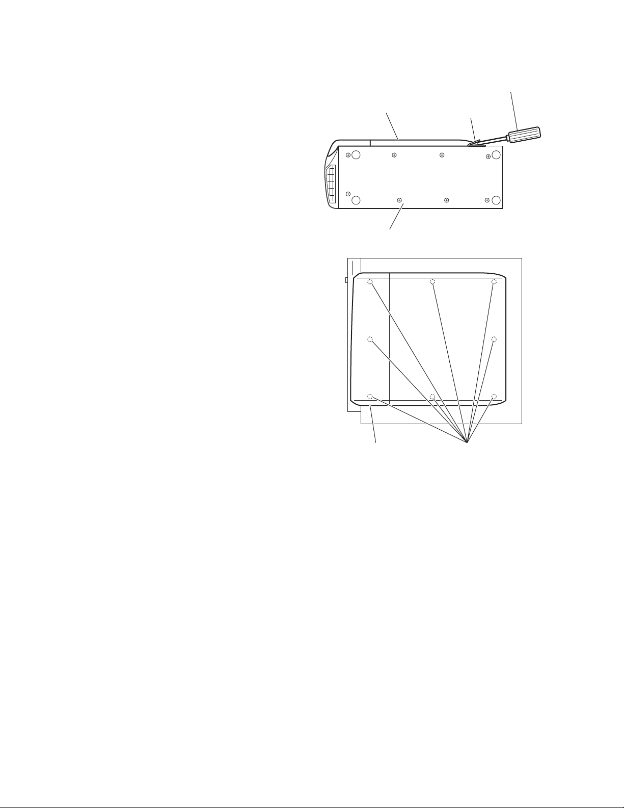
3.3.11 Removing the net assembly
(See Figs.16 and 17)
(1) From side of the speaker main body, insert the tip of the
flat-bladed screwdriver or similar tool into the space between the speaker main body and net assembly, and lift the
net assembly little by little to remove. (See Fig.16.)
Note:
To prevent damaging the net assembly and speaker
main body, insert cushioning plates etc. and below the
tip of the flat-bladed screwdriver or similar tool.
(2) From right side of the speaker main body, release the eight
joint c, and take out the net assembly from the speaker
main body. (See Fig.17.)
Net assembly
Speaker main body
Flat-bladed
screwdriver,etc.
Cushioning
plate,etc.
Fig.16
Net assembly
Joint c
Fig.17
1-24 (No.MB236)
Page 25
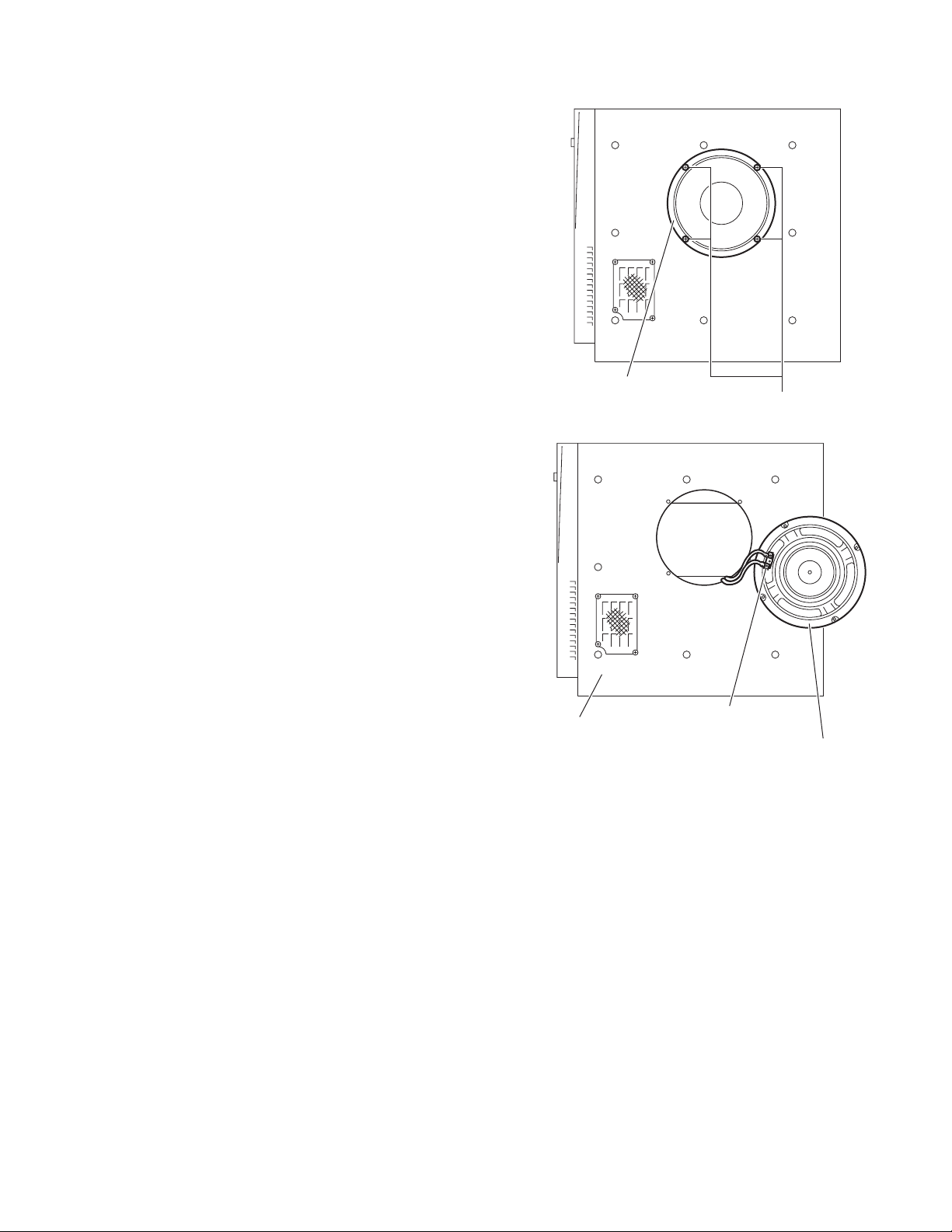
3.3.12 Removing the cone speaker
(See Figs.18 and 19)
• Prior to performing the following procedures, remove the net
assembly.
(1) From right side of the speaker main body, remove the four
screws Q attaching the cone speaker. (See Fig.18.)
(2) Take out the cone speaker from the speaker main body.
(See Fig.19.)
(3) Disconnect the wires from the terminal of the cone speak-
er. (See Fig.19.)
Cone speaker
Q
Fig.18
Speaker main body
Terminal
Cone speaker
Fig.19
(No.MB236)1-25
Page 26
SECTION 4
ADJUSTMENT
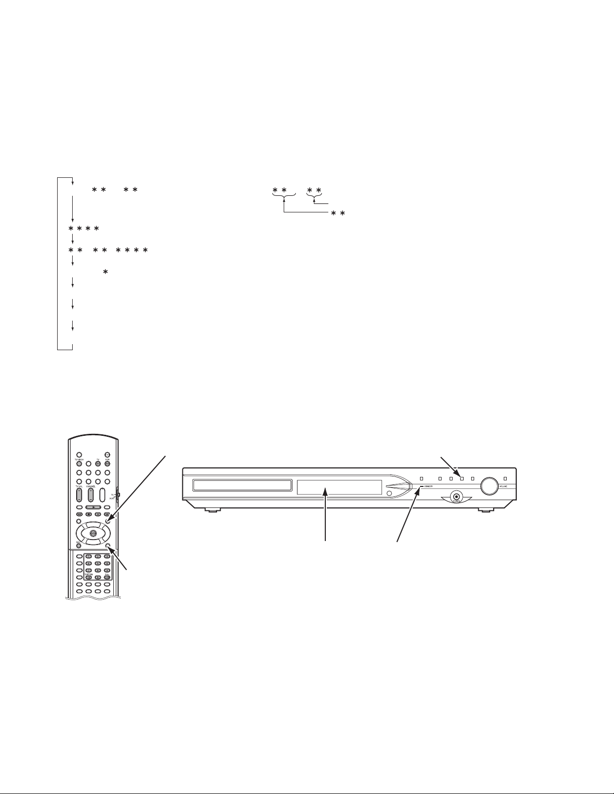
4.1 Test mode setting method
(1) Unplug the power plug.
(2) Insert power plug into outlet while pressing both "PLAY" key and "STANDBY/ON" key of the main body.
"Area code" is indicated at the upper left of display.
(3) To release test mode, press "STANDBY/ON" key of the main body.
NOTE:
Each pressing of "MENU" key of the remote controller in test mode changes the mode as follows.
TEST # -------------
-------------------------
FL Display and LED becomes all lighting
CHECK -------------------------
4.2 Method of displaying version of firmware
(1) Set the main body at test mode.
(2) Press "MENU" key of the remote controller twice. Then, version number and alphabetical letter of the system controller and the
back end are displayed in the FL display as follows.
(3) Each pressing of "ON SCREEN" key of the remote controller at the displaying version of firmware, changes the display as fol-
lows.
Becomes test mode
Checksum of device key
Version of microcomputer (Refer to "4.2 Method of displaying
Version of region code (Refer to "4.3 Method of displaying region code".)REGION -----------------------
Mechanism check mode (Refer to "4.6 Display of current value of laser".)
Expert modeEXPERT ------------------------
MENU key
(switch of mode)
#
BE microcomputer learning processing condition
: Area code
# : Region code
version firmware".) _ _ _--------
PLAY key
(for test mode)
1-26 (No.MB236)
ON SCREEN key
(for displaying version of firmware)
FL display
STANDBY/ON key
(for test mode)
Page 27
4.3 Method of displaying region code
(1) Set the main body at test mode.
(2) Press "MENU" key of the remote controller three times. Then, region code are displayed in the FL display.
4.4 Initialization method
Please initialize according to the following procedures in the following case:
• Just after you upgrade the firmware.
• After you confirm the symptoms that a customer points out. First Initialize, and then confirm whether the symptoms are improved or
not.
• After servicing, before returning the main body to a customer. (Initialized main body should be returned to a customer.)
(1) Set the main body at test mode.
(2) Press "PAUSE" key of the main body.
(3) When initialization is completed, "00" and "RDS" is displayed in the FL display.
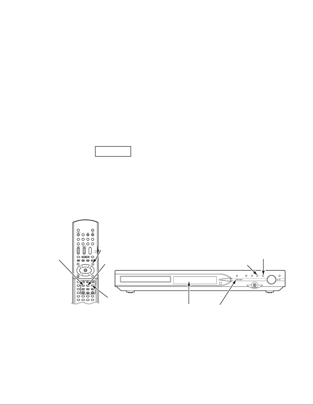
4.5 Display of current value of laser
(1) Set the main body at test mode.
(2) Press "MENU" key of the remote controller five times. Then, FL display is displayed "CHECK".
(3) The laser current value can be switched between the value of CD and that of DVD by pressing the following key of the remote
controller.
FL Display (Example)
1419 0000
Remote controller "4" key --- Laser of CD
Remote controller "5" key --- Laser of DVD
Remote controller "6" key --- Jitter measurement mode
• The number shown in the FL display shows mA of current value of laser.
• The first two numbers ("14" in "1419") shows current value of laser at the time of adjustment after the latest all-initialization, 14mA
in this example.
• The last two numbers ("19" in "1419") shows the present current value of laser, 19mA in this example.
• The first two numbers ("14" in "1419") usually shows current value of laser at the time of shipment, so you can see how the product
has been deteriorated by comparing the first two numbers ("14" in "1419") and the last two numbers ("19" in "1419").
CD and DVD:
The laser current value of 80mA or less in normal. The laser current value of over 81mA is not normal. Laser diode of the pickup
has been deteriorated.
• To return to test mode, press "STOP" key of the main body.
4 key
(laser of CD)
MENU key
(switch of mode)
5 key
(laser of DVD)
6 key
(display of jitter value)
FL display
PLAY key
(for test mode
and jitter value)
STANDBY/ON key
(for test mode)
PAUSE key
(for initialize)
(No.MB236)1-27
Page 28

4.6 Upgrading of firmware (DVD UPGRADE)
The latest firmware for upgrading is updated in "Optical disc CSG" page in JS-net. At the time of service, compare the version of the
product and the latest version, and upgrade the old version into the latest version.
(1) Press "STANDBY/ON" key of the main body to turn it on.
(2) Push "OPEN/CLOSE" key of the main body, and insert the upgrade disc in the tray.
(3) When reading the data of the disc, the OSD screen is displayed "VERSION UP DISC", "PROGRAM & DESTINATION MODE"
and "READING..".
(4) When the screen changes from "READING.." to "WRITING..", upgrading starts.
(5) After writing the data of the disc, the screen is displayed "OPEN".
(6) Take out the disc, and press "STANDBY/ON" key of the main body.
(7) When the stand-by indicator is lighted, upgrading is completed.
(8) Set the main body at test mode, and confirm the version of the firmware. (Refer to "4.2 Method of displaying version firmware".)
4.7 Upgrading of system microcomputer (ROM CORRECTION)
(1) Press "STANDBY/ON" key of the main body to turn it on.
(2) Push "OPEN/CLOSE" key of the main body, and insert the upgrade disc in the tray.
(3) When reading the data of the disc, the OSD screen is displayed "VERSION UP DISC", "SYSCON UPG MODE" and "READ-
ING..".
(4) When the screen changes from "READING.." to "WRITING..", system data is written.
(5) After writing the data of the disc, the FL display of the main body is displayed "COMPLETE".
(6) Take out the disc, and press "STANDBY/ON" key of the main body.
(7) When the stand-by indicator is lighted, upgrading is completed.
(8) Set the main body at test mode, and confirm the version of the system microcomputer. (Refer to "4.2 Method of displaying ver-
sion firmware".)
MENU key
(switch of mode)
AV COMPULINK terminal
FL display STANDBY/ON key
AV COMPULINK- terminal
OPEN/CLOSE key
(for upgrading of
system microcomputer
and firmware)
1-28 (No.MB236)
Page 29

4.8 Compulsive NTSC mode
(1) Unplug the power plug.
(2) Insert power plug into outlet while pressing both "PAUSE" key and "STANDBY/ON" key of the main body.
(3) The compulsive NTSC mode is set up.
NOTE:
In E series, Y/C mode is set up.
(4) Unless the mode is canceled, regardless of input of "NTSEL" switch, it starts only at the time of the first power-on.
(5) When power-off is carried out, the mode is canceled.
4.9 Locking disc tray
(1) Unplug the power plug.
(2) Insert power plug into outlet while pressing both "STOP" key and "OPEN/CLOSE" key of the main body.
(3) Then, the FL display of main body is displayed "LOCKED" and the disc tray is locked.
(4) For unlock the tray, press both "STOP" key and "OPEN/CLOSE" key.
(5) Then, the FL display of main body is displayed "UNLOCKED" and the tray is unlocked.
NOTE:
Unless unlocking disc tray, it does not process to input "OPEN/CLOSE" key.
4.10 Switching tuner AM step (U series only)
• Switching 9kHz
(1) Press both "STOP" key and "PLAY" key of the main body.
• Switching 10kHz
(1) Press both "STOP" key and "PAUSE" key of main body.
NOTE:
Switching tuner AM step is effective only when source is AM.
MENU key
(switch of mode)
STOP key
(for locking disc tray)
STANDBY/ON key
FL display
PLAY key
(for switching
tuner AM step)
PAUSE key
(for compulsive NTSC mode
and switching tuner AM step)
OPEN/CLOSE key
(for locking disc tray)
(No.MB236)1-29
Page 30

SECTION 5
TROUBLESHOOTING
This service manual does not describe TROUBLESHOOTING.
1-30 (No.MB236)
Page 31

(No.MB236)1-31
Page 32

Victor Company of Japan, Limited
AV & MULTIMEDIA COMPANY AUDIO/VIDEO SYSTEMS CATEGORY 10-1,1chome,Ohwatari-machi,Maebashi-city,371-8543,Japan
(No.MB236)
Printed in Japan
WPC
Page 33

SCHEMATIC DIAGRAMS
DVD DIGITAL CINEMA SYSTEM
TH-S9, TH-S8
TH-S7
CD-ROM No.SML200406
TH-S9
SP-THS9F SP-THS9S
SP-PWS9
SP-THS9F SP-THS9S
SP-PWS8
Area suffix
B ------------------------------ U.K.
E ---------- Continental Europe
EN ----------- Northern Europe
EV ------------- Eastern Europe
TH-S8
SP-THS9C
XV-THS9
SP-THS9C
SP-THS7F SP-TH7S
SD card
Contents
Block diagram
Standard schematic diagrams
Printed circuit boards
SP-THS9C
XV-THS7
TH-S9
SP-PWS7
TH-S8
Area suffix
B ------------------------------ U.K.
E ---------- Continental Europe
EN ----------- Northern Europe
XV-THS8
TH-S7
Area suffix
E ---------- Continental Europe
EN ----------- Northern Europe
EV ------------- Eastern Europe
TH-S7
2-1
2-2
2-14 to 18
COPYRIGHT 2004 Victor Company of Japan, Limited.
No.MB236SCH
2004/6
Page 34

In regard with component parts appearing on the silk-screen printed side (parts side) of the PWB diagrams, the
parts that are printed over with black such as the resistor ( ), diode ( ) and ICP ( ) or identified by the " "
mark nearby are critical for safety.
(This regulation does not correspond to J and C version.)
Page 35

Block diagram
<Main body section>
DVD servo section
CN101
DVD traverse
mechanism
DVD traverse
mechanism
Power section
P901
AC IN
IC901
SWITCH
REG.
DIODE
BRIDGE
A, B, C, D, E, F, RF+, PD(CD), PD(DVD)
LD(CD), LD(DVD)
FM+/WOUT
VOUT
UOUT
CN201
COM
F+/T+/-
IC201
DRVER
XV-THS9, XV-THS7
SD CARD
FL SW, -VDISP SW
B5V REG.
T901
POWER
TRANS.
D5V REG.
Q954,Q955
DVD5V SW
Q958 to Q961
A+/-12V REG.
FL section
IC511
REMOCON
X501
8MHz
IC501
DISPLAY
MICOM
DI501
FL DISPLAY
G1 to G13
S1 to S35
F+,F-,-VDISP
B5V,D5V
REMOCON
ILLUMI
DIMMER
Q551, Q552
ILLUMI. LED
Q951, Q953
IC953
IC951
DI-CK
DI-DT
DI-CS
DI-RST
D551
LPCO1, LPCO2
Q101 to Q104
CDLDCUR, DVDLDCUR
27MHz
SPDRV, TRSDRV, FODRV, TRDRV
/DRVMUTE, /SPMUTE, FG, VHALF
SD card interface section
CN801
F+,F-
-VDISP
FW901
B5V, D5V
DVD-PON
SYS-PON
M9V
D5V
DVD5V
A+12V
A-12V
CN501
D970
DVD3.3V
FW902
HEADPHONE
OUT
X351
IC301
DV2 .2
TRVSW
SDCLK
SDCD
SDCMD
SDDATA1
SDDATA2
SDDATA3
CN511
CN802
SDDATA4
System control section
CN406/CN407
B5V
D5V
SYS-PON, DVD-PON
CN404/CN405
DVD-5V
DVD-4V
M9V
+12V
-12V
Q4702
X4701
8MHz
Q4821
AM-BEAT
CUT
RESET-IN/RST
IC472
RESET
CN451
REMOCON
DI-CK, DI-DT
DI-CS, DI-RST
Key section
D511
STANDBY
LED
J6001
HP-L
HP-R
HP-DET
Q511
JS541
STANDBY
EXADT0 to 15, EXADR16 to 20
NEXCE, NEXOE, NEXWE
EXADT0 to 15
NEXCE
MA0 to 10, BA0, BA1
MDQ0 to 31, DQM0 to 3
NCSM,NRAS, NCAS, NWE, MCK
S2UDT
U2SDT
SCLK
SCS
CPURST
UCS
LRMUTE
SWMUTE
CN501
CN503 CN502 CN504
CN409
CN402 CN403 CN401
CPURST
SCS
S2UDT
IC471
SYSTEM
MICOM
AM-BEAT
S521 to S52
S526 to S528
OPERATION
KEY
VOL1
VOL2
KEY1
KEY2
IC509
FLASH ROM
LADD0 to 15
IC512, IC513
LATCH
IC505
SDRAM
AIN
BCK
LRCK
IC704
ADC
AINL
AINR
DAC0CS
DAC1CS
DAC2CS
DACPDN
D DATA
DCLK
AOUT0
AOUT1
AOUT2
IC701
RX
COUT
YOUT
CrOUT
CbOUT
COMPOUT
RX
DIN
U2SDT
UCS
IC473
SCLK
VOL-MUTE, VOL-DT, VOL-CK, SETUP, TU, L-R
SW-PON
S-MUTE
Q4811, Q4812
SW-PON
Q4801, Q4802
S-MUTE
DRIVER
to
IC703
DAC
FAOUTL
FAOUTR
RAOUTL
RAOUTR
CAOUT
SWAOUT
ADINL
ADINR
C, CV-Y1, Y2-G
CB-B, CR-R
U2SDT
UCS
SCLK
HP-L
IC601
HP-R
HP
IC476
AMP.
AMP.
TU-DI, TU-DO
TU-CK, TU-CE
VOL- 1
VOL- 2
CN452
CN511
STAND-BY
KEY1
KEY2
HPDET
HP-L
HP-R
OPENSW, CLOSESW
Audio signal input/output section
SW.P.ON, SETUP
Q1131
S_MUTE
Q1133
Q1135
S.MUTE
Q1251
Q1252
TU_L, TU_R
IC531
OUT-L
AMP.
OUT-R
Video input/output section
VIDEO-MUTE1
VIDEO-MUTE2
VIDEO-YCMIX
VIDEO-RGB
VIDEO-LPF
TU-L, TU-R
TU-SW
TU-PON
Q4091, Q4092
TU9V REG.
TRAY+
TRAY-
IC152
IC581
IC591
AUDIO
SW
AMP.
CN442 CN441
CN412 CN411
OUT-L, OUT-R
IC474
SW
HPOUT-L
HPOUT-R
TOPE N
TCLOSE
TU-SW
&
OUT-C
OUT-SW
OUT-SL
OUT-SR
SWPON
AUX- L
AUX- R
SMUTE
IC493
TRAY DRV.
L-R
TUNER
+IN 1, +IN 2
C IN, SW IN
VOL_MUTE
VOL_DT
VOL_CK
IC151
AUDIO
DRIVER
CR-R
CB-B
Y2-G
C
CV-Y1
CV-Y1
R/C
IC475, IC478
TUNER AMP.
AVC-OUT
AVC-IN
IC158
to
IC160
AMP.
IC153
6CH
VOL.
SW
IC431
VIDEO
C
CV
IC441
VIDEO
SW
C
R
SCART-LIN, SCART-RIN
TU9V
Q4703
C, SW
SL, SR
L, R
HPOUT_L
HPOUT_R
DIN
AUX- L
AUX- R
Cr
Cb
Y
R/C
TU-L
TU-R
AVVLR
J1103
SYSTEM
CONN.
IC509
DIGITAL
IN
J1101
AUX IN
COMPONENT
VIDEO OUT
CV
G
SCART
B
TERMINAL
CN410
CN408
TO
TRAY
MOTOR
J4891J4403J4402
AV
COMPULINK
Tu ne r
Pack
<Subwoofer section>
Amplifier section
IC201
Mini Din
CONN.
AC IN
POWER
AMP.
IC202
POWER
AMP.
C, SW
SL, SR
J2701
L, R
CN273 CN272 CN271
CN502 CN372 CN501
Q523 to Q525
PROTECTOR
PROTECT
P.ON_SIG
P.ON_SIG
P.ON_SIG
LOW VOLTAGE
Q501 to Q505
POWER CONTROL
& PROTECTOR
+5V
Q152
5V_REG.
+7V
D165
7V_REG.
+VH, -VH
+VL, -VL
CN101
RY101
Power/Micom
section
RY271
RY272
RY273
SP_RELAY-
Q542
DETECTOR
CN102
SW_SIG
SR_SIG
AD_SL
AD_C
SW_SIG
IC303
AMP.
Q603
Q604
IC602
RESET
FAN O N
+12V
Q151
12V_REG.
-7V
D166
-7V_REG.
D151, D152
CN151
POWER
TRANS.
IC302
AMP.
IC601
MICOM
Q3702
Q3703
Q3704
FAN
DRV.
T101
IC301
AMP.
AD_L
AD_R
LED
FLOUT
J2702
FROUT
FCOUT
SLOUT
SROUT
CN274
TO SW
SPEAKER
FW501 CN371
D561
LED
MOTOR
FAN
2-1
Page 36

Standard schematic diagrams
<Main body section>
Power section
(SHEET 2)
Parts are safety assurance parts.
When replacing those parts make
sure to use the specified one.
2-2
(SHEET 2)
SHEET 1
Page 37

System control section
TO FW901
OF LVA10466-A2
(SHEET 1)
(SHEET 5)
(SHEET 5)
TO CN504 OF LVA10513-321A (SHEET 8)
TO CN504 OF LVA10513-31A (SHEET 10)
TO CN502
OF LVA10513-321A
(SHEET 8)
TO CN503
OF LVA10513-321A
(SHEET 8)
TO CN501
OF LVA10513-321A
(SHEET 8)
TO FW902
OF LVA10466-A2
TO CN502
OF LVA10513-31A
TO CN503
OF LVA10513-31A
TO CN501
OF LVA10513-31A
(SHEET 1)
(SHEET 10)
(SHEET 10)
(SHEET 10)
(SHEET 3)
TO Video input / output section
(SHEET 4) (SHEET 4)
Parts are safety assurance parts.
When replacing those parts make
sure to use the specified one.
SHEET 2
2-3
Page 38

Video input / output section
(SHEET 2)
TO System control section
(SHEET 2)
TO System control section
2-4
SHEET 3
Page 39

FL and Key section
TO CN452
OF LVA10466-A1
(SHEET 2)
TO CN451
OF LVA10466-A1
(SHEET 2)
SHEET 4
2-5
Page 40

Audio signal input / output section
(SHEET 2)
TO CN412 OF LVA10466-A1
(SHEET 2)
TO CN411 OF LVA10466-A1
2-6
SHEET 5
Page 41

SD card interface section [XV-THS9, XV-THS7]
(SHEET 8)
TO CN511 OF LVA10513-321A
SHEET 6
2-7
Page 42

DVD servo section (1/2) [XV-THS9, XV-THS7]
MDQ6
DQM1
NRAS
NCAS
DQM0
NWE
MDQ7
MDQ8
BA0
BA1
NCSM
MA10
DQM2
DQM3
MDQ16
MDQ31
MDQ17
MDQ30
MDQ18
MDQ29
MDQ19
MDQ28
MDQ20
MDQ27
MDQ21
MDQ26
MDQ22
MDQ25
MDQ23
MDQ24
MA3
MA4
MA2
MA5
MA1
MA6
MA0
MA7
MA8
MA9
MCK
TP20
C103
C104
CN101
QGF0523F1-24W
TP1
QGF1037F1-08W
CN201
TP28
TP980
DGND
TP990
DGND
IC302
LM1117MP-ADJ-X
27
R303
C307
0.1/16
LPC2
LPC1
TP12
TP13
TP14
TP15
TP16
TP17
TP18
TP19
C101
0.1/16
VREFH
K101
0
C102
E
0.1/16
F
C109
D
A
B
R124
C
RF+
R122
C107
0.1/16
TP4
TP3
TP2
TP24
TP25
TP26
TP27
C980
NI
0
R990
R101
0.1/16
R102
F+
F-
T+
T-
TP8
TP9
TP7
TP6
TP5
TP10 TP11
FM+
FM-
WOUT
VOUT
UOUT
COM
TP22
TP23
TP21
0
100
K102
0
C111
1000.1/16
MGND
NI
R126
180
TP03
COM
C260
C261
NI
C263
0.1/16
M9V
C217
R256
NI
R257
TP220
R255
NI
SPDRV
CDLDCUR
NI
NI
C110
NI
NI
R121
0
R120
R123
0
R119
NI
D101
VOUT
UOUT
0.022
0.022
C262
0.022
R252
2.2
R251
0.47
R259
0
R221
10k
C256
0.1/16
TP221
R215
NI
R111
WOUT
6.8k
TRSDRV
C108
27
R113
R112
30k
KTA1001/Y/-X
2SC4617/R/-X
24k
Q105
UN2119-X
FM+
R213
10k
C211
0.022
10k
R214
LPCO2
DVDLDCUR
47/6.3
2.2
470
R116
R114
R118
R115
Q104
330
R117
T+
F+
F-
T-
FM-
IC201
LA6502-X
R207
0.0082
47k
C206
C257
C251
C258
C259
0.47/10
0.015/16
0.015/16
R254
TP226
FG
C106
27
R105
0
R104
30k
Q101Q103
KTA1001/Y/-X
2SC4617/R/-X
24k
R103
NI
C204
C264
0.1/16
C205
270p
R206
30k
R219
18k
24k
R220
150p
27k
TP231
R205
NI
/SPMUTE
FODRV
/DRVMUTE
LPCO1
S5V
1
R125
47/6.3
0
470
2.2
R106
R110
R108
R107
100100
Q102
R109
M5V
R204
27k
R208
TP227
1/6.3
C371
TP09
NI
R201
VHALF
33k
R127
AD4
R128
C105
16k
470
47/6.3
/HFMON
TRVSW
TP310
TP0
TRDRV
NI
R384
1k
1k
R385
UCS
MDQ9
MDQ5
MDQ10
MDQ4
MDQ11
MDQ3
MDQ12
MDQ2
MDQ13
MDQ1
MDQ14
MDQ0
MDQ15
C328 C311
0.1/16
EXADR20
NEXWE
EXADT0
EXADT4
EXADT8
EXADT12
EXADR16
EXADR18
EXADT14
EXADT10
C300
0.1/16
EXADT6
EXADT2
NEXCE
EXADT1
EXADT5
EXADT9
EXADT13
EXADR17
C329
EXADR19
EXADT15
0.1/16
EXADT11
EXADT7
EXADT3
NEXOE
R/B
SDMODE
R419
DAC0CS
DCLK
DDATA
DACPDN
/FL_RST
NI
R368
330
R356
330
R355
330
R369
330
10k
R452
CPURST
FG
0
IC453
R372
10k
1k
SPDRV
TRSDRV
S-80830CNNB-G-W
TP327
HAGUP
22k
R308
10k
R373
C351
0.01/16
C352
0.015/16
SWMUTE
100
100
NI
TP304
/TALK
R381
R353
R354
1/6.3
LRMUTE
R320
S2UDT
U2SDT
SCLK
SCS
R457
0.01/16
C455
C308
0.1/16
100k
R309
C310
R458
1k
C306
0.1/16
IC301
MN2DS0004AA-H
NI
C309
0.1/16
TP329
TP328
R383
R399
/HFMON
/SPMUTE
/DRVMUTE
TRVSW
0
0
100
100
R416
R415
R418
R417
R429
NI
R428
NI
R421
47k
R422
47k
R423
47k
R424
1M
R425
47k
R426
47k
R427
12k
SDWP
SDCD
SDCLK
SDCMD
0
000
R414
SDDATA4
R413
SDDATA3
R412
SDDATA2
0
R411
SDDATA1
0.033/16
C333
C332
C331
0.1/16
0.1/16
C334
C335
0.1/16
0
R314
TP314
TP315
C337
0.018/16
0.1/16
C338
0.1/16
C348
0.1/16
C350
C330
0.1/16
0.0056
0
150
R313
R363
RF+
C305
0.1/16
R340
000
R393
0.1/16
0.1/16
0.1/16
0.1/16
0.1/16
0.1/16
0.1/16
C322
C323
C320
C321
C319
C347
C314
C349
0.1/16
0
R312
LPC2
LPCO1
LPC1
1/6.3
1/6.3
C340
C324
LPCO2
VREFH
VHALF
P3.3V
D1.2V
R301
NI
R302
C303
330
330
330
NI
330
220
220
220
220
220
100
NAX0550-001X
680
1M
X351
R345
100
R316
C318
3.6k
20k
22k
C354
TH301
R343
0
C326
R315
6.8
R341
R317
0
C353
DVDLDCUR
CDLDCUR
0
FODRV
TRDRV
47/4
TX
AOUT0
AOUT1
AOUT2
AIN
BCK
LRCLK
RX
C325
18p
15p
PCMCLK
DAC5OUT
DAC4OUT
DAC3OUT
DAC2OUT
DAC1OUT
560p
560p
AD4
R319
0
A
B
C
D
E
F
R392
10k
TP305
S3.3V
NQR0502-001X
C301
C302
47/4
TP325
TP320
TP319
TP317
C315
0.1/16
0.1/16
C341
C356
C316
R394
DGND
R330
R331
R332
R333
R307
1k
R306
1k
R362
R357
R360
R359
R358
R367
R562
NI
R351
R366
R352
C313
0.1/16
C339
0.1/16
1/10
R342
30k
1/16
0.1/16
C327
C317
R334
R335
R336
R337
R338
R339
C391
2.2k 0.1/16
C312
0.1/16
R347
R346
NI
R395
4.7k
0.1/16
150
150
150
150
0
0
0.1/16
NAD0025-103X
D2V
(SHEET 8)
24
C304
1/6.3
ADCRST
DAC1CS
DAC2CS
DEMP
TP316
TP318
DGND
K352
220/4
NI
CN301
2-8
SHEET 7
Page 43

DVD servo section (2/2) [XV-THS9, XV-THS7]
(SHEET 7)
LADD15
LADD14
LADD13
LADD12
LADD11
LADD10
LADD9
LADD8
EXADR19
EXADR20
NEXWE
/FL_RST
R/B
EXADR18
EXADR17
LADD7
LADD6
LADD5
LADD4
LADD3
LADD2
LADD1
NQR0022-005X
NQR0022-005X
NQR0022-005X
NQR0022-005X
NQR0022-005X
NQR0022-005X
NQR0022-005X
NQR0022-005X
NQR0022-005X
K561
K562
K563
K564
K565
K566
K567
K568
K552
K556
K553
K554
K551
M5V
S3.3V
TP96
TP94
TP93
TP92
TP91
K791
NQR0502-001X
TP99
TP98
TP97
TP90
TP95
QGF0523F1-16W
CN511
TO CN802
OF LVA10487
(SHEET 6)
DGND
TP38
TP37
TP32
TP35
TP31
TP34
TP33
CN501
NI
NI
NI
NI
NI
NI
NI
NI
TP46
TP44
TP45
NQR0129-002X
NQR0129-002X
NQR0129-002X
NQR0129-002X
NQR0129-002X
TP54
TP55
S5V D2V
M9V
TP56TP76
QGF1016F2-08W
TO CN409
OF LVA10466-A1
(SHEET 2)
TP43
TP41
TP42
QGF1016F2-09W
CN502
TO CN403
OF LVA10466-A1
(SHEET 2)
TP51
TP52
TP53
TO CN402
OF LVA10466-A1
(SHEET 2)
SDCLK
IC711
IC505
0.1/16
LADD0
LADD1
LADD2
LADD3
LADD8
LADD9
LADD10
LADD11
C552
IC512
SN74LVC373APW-X
0.1/16
C553
IC513
SN74LVC373APW-X
LADD7
EXADT7
EXADT6
LADD6
LADD5
EXADT5
EXADT4
LADD4
NEXCE
LADD15
EXADT15
EXADT14
LADD14
LADD13
EXADT13
EXADT12
LADD12
NEXCE
MDQ0
MDQ1
MDQ2
MDQ4EXADT6
MDQ5
MDQ6
MDQ7
DQM0
NWE
NCAS
NRAS
NCSM
BA0
BA1
MA10
MA0
MA1
MA2
DQM2
MDQ16
MDQ17
MDQ18
MDQ19
MDQ20
MDQ21
MDQ22
0.1/16
C551
C555
0.1/16
IC509
AT49BV322AT70TI
R533
0
R534
10k
R535
NI
IC508
NI
R502
IC507
NI
EXADR16
R531
10k
C554
EXADT15
EXADT0
0.1/16
EXADT7
EXADT1
EXADT14 MDQ3
EXADT13
EXADT2
EXADT5
EXADT3
EXADT12
EXADT4
EXADT11
EXADT3
EXADT10
EXADT2
EXADT9
EXADT1
EXADT8
EXADT0
EXADT8
EXADT9
EXADT10
EXADT11
LADD0
0
R501
NEXCE
NEXOE
NI
C559
0
R530
10k
NEXCE
K4S643232F-TC60
MDQ15
MDQ14
MDQ13
MDQ12
MDQ11
MDQ10
MDQ9
MDQ8
C557
0.1/16
DQM1
MCK
MA9
MA8
MA7
MA6
MA5
MA4
MA3
DQM3
MDQ31
MDQ30
MDQ29
MDQ28
MDQ27
1/10
C556
MDQ26
MDQ25
MDQ24MDQ23
C558
47/4
PCMCLK
AIN
BCK
LRCLK
ADCRST
P3.3V
S3.3V
IC305
K350
NQR0502-001X
DGND
NI
C751
IC707
IC706
NI
NI
K757
K710
K766
K767
NI
NI
NI
NQR0129-002X
NI
K752
R751
R759
K759
K758
NI NI
R758
R711
R716
220
MM1563DF-X
C381
2.2/10
C382
470p
TP02
NI
C761
NI
NI
0.1/16
R754
R755
NI
NI
NI
TP753
R761
NI
CN505
TP751
TP752
C743
2.2/16
R745
10k
C742
2.2/16
10k
R388
1/16
C380
4.7
4.7
R743
R744
IC704
CS5342-CZZ-X
C748
2.2/16
C749
2.2/16
R749
5.1
R742
47k
R793
NI
R792
0
R715
R714
NI
NI
C741
2.2/16
C714
C715
NI
C793
NI
220
220
TP01
R794
NI
C791
C794
NI
K591
SDMODE
K592
SDCD
K593
SDWP
K594
SDCMD
NI
K595
K596
SDDATA4
K597
SDDATA3
SDDATA2
K598
K599
SDDATA1
CPURST
S2UDT
U2SDT
SCLK
SCS
UCS
LRMUTE
SWMUTE
DAC5OUT
DAC4OUT
DAC3OUT
DGND
DAC2OUT
DAC1OUT
RX
K555
TX
NQR0022-005X
AOUT0
AOUT1
AOUT2
DACPDN
DAC0CS
DCLK
DDATA
DAC1CS
DAC2CS
MGND
TP61
TP60
TP58
TP59
IC701
AK4384VT-X
C707
0.1/16
C706
IC702
AK4384VT-X
IC703
AK4384VT-X
47k
R718
10/10
C708
0.1/16
C702
0.1/16
C705
NI
C709
0.1/16
R741
0
R701
0
C701
0.1/16
C704
47/6.3
C703
0.1/16
MM1615AN-X
IC705
C711
C712
1/16
C713
1/16
0.01/16
R731
R703
0
470
R732
R704
0
470
R705
470
R733
R706
0
470
R734
R707
0
470
R735
R708
0
470
NI
NI
NI
NININI
NI
K724
K725
R728
R729
K722
K721
K723
NININININI
K731
K730
K732
DACPDN
AIN
DEMP
LRCLK
AOUT2
AOUT1
AOUT0
BCK
DAC0CS
DGND
TP57
TP71
TP75
TP73 TP36
TP74
TP72
CN504 CN503
QGF1016F2-15W QGF1016F2-17W
NI
K729
TO CN401
OF LVA10466-A1
(SHEET 2)
TP78
TP81
TP79
TP77
TP82
TP80
NININI
K735
K734
K736
K733
DCLK
DAC1CS
DDATA
DAC2CS
SHEET 8
2-9
Page 44

DVD servo section (1/2) [XV-THS8]
MDQ6
DQM1
NRAS
NCAS
DQM0
NWE
MDQ7
MDQ8
BA0
BA1
NCSM
MA10
DQM2
DQM3
MDQ16
MDQ31
MDQ17
MDQ30
MDQ18
MDQ29
MDQ19
MDQ28
MDQ20
MDQ27
MDQ21
MDQ26
MDQ22
MDQ25
MDQ23
MDQ24
MA3
MA4
MA2
MA5
MA1
MA6
MA0
MA7
MA8
MA9
MCK
TP20
C103
C104
CN101
QGF0523F1-24W
TP1
CN201
QGF1037F1-08W
TP27
TP28
TP980
DGND
TP990
R990
DGND
IC302
LM1117MP-ADJ-X
27
R303
C307
0.1/16
LPC2
LPC1
TP12
TP13
TP14
TP15
TP16
TP17
TP18
TP19
C101
0.1/16
VREFH
K101
0
C102
E
0.1/16
F
C109
D
A
B
R124
C
RF+
R122
R101
0.1/16
C107
0.1/16
TP4
TP3
TP2
TP24
TP25
TP26
C980
NI
0
R102
F+
F-
T+
T-
TP9
TP7
TP6
TP5
TP8
TP10 TP11
FM+
FM-
WOUT
VOUT
UOUT
COM
TP22
TP23
TP21
0
100
K102
0
C111
1000.1/16
MGND
NI
R126
180
TP03
COM
C260
C261
C262
NI
C263
0.1/16
M9V
C217
R256
NI
R257
TP220
R255
NI
SPDRV
CDLDCUR
NI
NI
C110
NI
NI
R121
R120
R123
0
R119
NI
D101
0.022
0.022
0.022
R251
0.47
R259
0
10k
C256
0.1/16
TP221
R215
27
R113
R112
0
30k
KTA1001/Y/-X
2SC4617/R/-X
24k
R111
Q105
UN2119-X
FM+
WOUT
VOUT
UOUT
R252
2.2
6.8k
R221
R213
10k
C211
0.022
10k
R214
NI
TRSDRV
LPCO2
DVDLDCUR
C108
47/6.3
2.2
470
R116
R114
R118
R115
Q104
330
R117
T-
T+
F+
F-
FM-
IC201
LA6502-X
R207
0.0082
47k
C206
C257
C258
C259
C251
0.47/10
0.015/16
0.015/16
TP226
R254
FG
C106
27
R105
0
R104
30k
Q101Q103
KTA1001/Y/-X
2SC4617/R/-X
24k
R103
NI
C204
C264
0.1/16
C205
270p
R206
30k
R219
18k
24k
R220
150p
27k
TP231
R205
NI
/SPMUTE
FODRV
/DRVMUTE
LPCO1
S5V
1
R125
47/6.3
0
470
2.2
R106
R110
R108
R107
100100
Q102
R109
M5V
R204
27k
R208
TP227
1/6.3
C371
TP09
NI
R201
VHALF
33k
R127
AD4
R128
C105
470
16k
47/6.3
/HFMON
TRVSW
TP310
TP0
TRDRV
NI
R384
1k
1k
R385
UCS
EXADR20
NEXWE
EXADT0
EXADT4
EXADT8
EXADT12
EXADR16
EXADR18
EXADT14
EXADT10
EXADT6
EXADT2
NEXCE
EXADT1
EXADT5
EXADT9
EXADT13
EXADR17
EXADR19
EXADT15
EXADT11
EXADT7
EXADT3
NEXOE
R/B
SDMODE
DAC0CS
DCLK
DDATA
DACPDN
/FL_RST
MDQ9
MDQ5
MDQ10
MDQ4
MDQ11
MDQ3
MDQ12
MDQ2
MDQ13
MDQ1
MDQ14
MDQ0
MDQ15
C328
0.1/16
C300
0.1/16
C329
0.1/16
R419
NI
330
R368
R356
330
R355
330
R369
330
10k
FG
0
IC453
1k
R452
CPURST
S-80827CNNB-W
R372
TRSDRV
10k
SPDRV
TP327
HAGUP
22k
R308
10k
R373
C351
0.01/16
C352
0.015/16
SWMUTE
100
100
NI
TP304
/TALK
R381
R353
R354
1/6.3
LRMUTE
R320
S2UDT
U2SDT
SCLK
SCS
R457
C455
0.01/16
C308
0.1/16
100k
R309
C310
R458
1k
C306
0.1/16
IC301
MN2DS0004AA-H
C309
0.1/16
NI
TP328
TP329
R383
R399
/HFMON
/SPMUTE
/DRVMUTE
TRVSW
NININI
NI
R416
R415
R418
R417
NI
R429
NI
R428
NI
R421
NI
R422
NI
R423
NI
R424
R425
NI
NI
R426
NI
R427
SDWP
SDCD
SDCLK
SDCMD
0
NININI
R414
SDDATA4
R413
SDDATA3
R412
SDDATA2
NI
R411
SDDATA1
0.033/16
C331
C333
C332
0.1/16
0.1/16
C334
C335
0.1/16
0
R314
TP314
TP315
C337
0.018/16
0.1/16
C338
0.1/16
C348
C350
0.1/16
C330
0.1/16
0.0056
0
150
R363
R313
RF+
C305
0.1/16
R340
000
R393
0.1/16
0.1/16
0.1/16
0.1/16
0.1/16
0.1/16
0.1/16
C322
C323
C320
C321
C314
C319
C347
C349
0.1/16
0
R312
LPC1
1/6.3
1/6.3
C340
C324
LPCO2
VREFH
VHALF
LPC2
LPCO1
P3.3V
D1.2V
R301
NI
R302
C303
NAX0550-001X
680
1M
R345
100
R316
C318
20k
22k
C354
TH301
47/4
330
330
330
NI
TX
330
AOUT0
220
AOUT1
220
AOUT2
220
AIN
BCK
220
LRCLK
220
RX
100
C325
18p
X351
C326
15p
PCMCLK
R315
0
DAC5OUT
R343
DAC4OUT
0
6.8
R341
DAC3OUT
3.6k
DAC2OUT
R317
DAC1OUT
0
FODRV
TRDRV
C353
560p
560p
AD4
DVDLDCUR
R319
0
CDLDCUR
A
B
C
D
E
F
R392
10k
TP305
S3.3V
NQR0502-001X
C301
C302
47/4
TP325
TP320
TP319
TP317
C315
0.1/16
C311
0.1/16
C341
C356
C316
R394
DGND
R330
R331
R332
R333
R307
1k
R306
1k
R362
R357
R360
R359
R358
R367
R562
NI
R351
R366
R352
C313
0.1/16
C339
0.1/16
1/10
30k
1/16
0.1/16
R342
C327
C317
R334
R335
R336
R337
R338
R339
C391
2.2k 0.1/16
C312
0.1/16
R347
R346
NI
0.1/16
0.1/16
R395
4.7k
150
150
150
150
0
0
NAD0025-103X
D2V
(SHEET 10)
24
C304
1/6.3
ADCRST
DAC1CS
DAC2CS
DEMP
TP316
TP318
DGND
K352
220/4
NI
CN301
2-10
SHEET 9
Page 45

DVD servo section (2/2) [XV-THS8]
(SHEET 9)
LADD15
LADD14
LADD13
LADD12
LADD11
LADD10
LADD9
LADD8
EXADR19
EXADR20
NEXWE
/FL_RST
R/B
EXADR18
EXADR17
LADD7
LADD6
LADD5
LADD4
LADD3
LADD2
LADD1
SDCLK
IC711
IC505
0.1/16
LADD0
LADD1
LADD2
LADD3
LADD8
LADD9
LADD10
LADD11
C552
IC512
SN74LVC373APW-X
C553
IC513
SN74LVC373APW-X
0.1/16
C551
MDQ0
LADD7
MDQ1
EXADT7
MDQ2
EXADT6
LADD6
LADD5
MDQ4EXADT6
EXADT5
EXADT4
MDQ5
MDQ6
LADD4
NEXCE
MDQ7
LADD15
EXADT15
EXADT14
LADD14
LADD13
EXADT13
EXADT12
LADD12
NEXCE
DQM0
NWE
NCAS
NRAS
NCSM
BA0
BA1
MA10
MA0
MA1
MA2
DQM2
MDQ16
MDQ17
MDQ18
MDQ19
MDQ20
MDQ21
MDQ22
C555
0.1/16
0.1/16
IC509
AT49BV322AT70TI
R533
0
R534
10k
R535
NI
IC508
NI
R502
IC507
NI
EXADR16
R531
10k
C554
EXADT15
EXADT0
0.1/16
EXADT7
EXADT1
EXADT14 MDQ3
EXADT13
EXADT2
EXADT5
EXADT3
EXADT12
EXADT4
EXADT11
EXADT3
EXADT10
EXADT2
EXADT9
EXADT1
EXADT8
EXADT0
EXADT8
EXADT9
EXADT10
EXADT11
LADD0
0
R501
NEXCE
NEXOE
NI
C559
0
10k
R530
NEXCE
K4S643232F-TC60
MDQ15
MDQ14
MDQ13
MDQ12
MDQ11
MDQ10
MDQ9
MDQ8
C557
0.1/16
DQM1
MCK
MA9
MA8
MA7
MA6
MA5
MA4
MA3
DQM3
MDQ31
MDQ30
MDQ29
MDQ28
MDQ27
C556
1/10
MDQ26
MDQ25
MDQ24MDQ23
C558
47/4
PCMCLK
AIN
BCK
LRCLK
ADCRST
P3.3V
S3.3V
IC305
K350
NQR0502-001X
DGND
NI
C751
IC707
IC706
NI
NI
K757
K710
K766
K767
NI
NI
NI
NQR0129-002X
NI
K752
R751
R759
K759
K758
NI NI
R758
R711
R716
220
MM1563DF-X
C381
2.2/10
470p
C382
TP02
NI
C761
NI
NI
0.1/16
R754
R755
NI
NI
NI
TP753
R761
NI
CN505
TP751
TP752
C743
2.2/16
R745
10k
C742
2.2/16
10k
R388
1/16
C380
4.7
4.7
R743
R744
IC704
CS5342-CZZ-X
C748
2.2/16
C749
2.2/16
R749
5.1
R742
47k
R793
NI
R792
NI
R715
NI
NI
R714
C741
2.2/16
C714
C715
NI
C793
NI
220
220
TP01
R794
NI
C791
C794
NI
K591
SDMODE
SDCD
K592
SDWP
K593
SDCMD
K594
NI
K595
SDDATA4
K596
SDDATA3
K597
SDDATA2
K598
SDDATA1
K599
CPURST
S2UDT
U2SDT
SCLK
SCS
UCS
LRMUTE
SWMUTE
DAC5OUT
DAC4OUT
DAC3OUT
DGND
DAC2OUT
DAC1OUT
RX
K555
TX
NQR0022-005X
S3.3V
TP94
TP93
TP92
TP91
TP99
TP98
TP97
K791
NI
NI
NI
NI
NI
NI
NI
NI
NI
DGND
TP38
NI
K561
NI
K562
NI
K563
NI
K564
NI
K565
K566
NI
K567
NI
NI
K568
TP46
K552
NQR0129-002X
K556
NQR0129-002X
K553
NQR0129-002X
K554
NQR0129-002X
K551
NQR0129-002X
S5V D2V
M5V
M9V
TP56TP76
TP90
TP95
TP96
TP37
NI
CN511
TP32
TP35
TP31
TP34
TP33
QGF1016F2-08W
CN501
TO CN409
OF LVA10466-A1
(SHEET 2)
TP41
TP42
TP44
TP45
TP43
QGF1016F2-09W
CN502
TO CN403
OF LVA10466-A1
(SHEET 2)
TP51
TP52
TP53
TP54
TP55
TO CN402
OF LVA10466-A1
(SHEET 2)
AOUT0
AOUT1
AOUT2
DACPDN
DAC0CS
DCLK
DDATA
DAC1CS
DAC2CS
MGND
TP58
TP59
TP57
TP61
NI
K736
DAC2CS
TP60
TP74
TP75
TP71
TP72
TP73 TP36
QGF1016F2-15W QGF1016F2-17W
CN504 CN503
TO CN401
OF LVA10466-A1
(SHEET 2)
TP82
TP80
TP78
TP81
TP79
TP77
IC701
AK4384VT-X
C707
0.1/16
C706
IC702
AK4384VT-X
IC703
AK4384VT-X
47k
R718
10/10
C708
0.1/16
C702
0.1/16
C705
NI
C709
0.1/16
R741
0
R701
0
C701
0.1/16
C704
47/6.3
C703
0.1/16
MM1615AN-X
IC705
C711
1/16
C712
1/16
C713
0.01/16
R731
R703
R704
R705
R706
R707
R708
0
470
R732
0
470
470
R733
0
470
R734
0
470
R735
0
470
NI
NININI
NININI
K722
K721
K723
K724
AOUT2
AOUT1
AOUT0
BCK
K729
NI
K725
R728
R729
NININININI
NININI
K735
K734
K731
K730
K732
K733
DACPDN
AIN
DEMP
LRCLK
DAC0CS
DCLK
DAC1CS
DDATA
DGND
SHEET 10
2-11
Page 46

<Subwoofer section>
(
)
(
)
Amplifier section
OF LVA10494-A2
(SHEET 12)
Parts are safety assurance parts.
When replacing those parts make
sure to use the specified one.
2-12
OF LVA10494-A2
SHEET 12
OF LVA10494-A2
SHEET 12
SHEET 11
Page 47

Power / Micom section
OF LVA10494-A1
(SHEET 11)
OF LVA10494-A1
(SHEET 11)
OF LVA10494-A1
(SHEET 11)
Parts are safety assurance parts.
When replacing those parts make
sure to use the specified one.
SHEET 12
2-13
Page 48

Printed circuit boards
<Main body section>
Main board [XV-THS9, XV-THS8]
C4903
C4719
D4833
D4834
D4835
C4904
HS491
IC491
CN404
CN405
CN406
CN407
D4831
W4001
C4892 C4891
J4891
D4891
C4013
R4892
D4832
Q4831
C4901
D4998
R4961
C4961
D4961
C4718
R4841
Q4832
K4701
C4902
Q4833
CP471
EP401
D4997
R4833
R4834
R4832
R4835
R4705
D4704
R4831
Q4961
C4704
C4004
R4891
D4811
C4706
IC472
R4072
Q4811
Q4702
CN416
Q4812
K4702
R4706
C4077
R4073
C4075
R4811
C4703
D4703
C4432
R4888 R4889
C4702
R4704
R4074
R4703
C4076
R4431
C4442
J4402
C6202
Q4802
C4078
R4780
R4778
R4777
R4775
R4776
Q4701
C4079
R6303
C6102
R6103
X4071
C4071
C6203
R6203
R6202
C6104
R6611
R4887
C4073
C4074
R6612
R4802
R4801
Q4801
PP401
C4714
R6102
R6101
C4801
IC481
D4706
IC601
C6901
R6105
R4441
R4890
Q4821
R6106
R4758
R4885
R4821
D4964
D4965
R6207
C6103
IC471
D4707
R4822
R6206
R6302
R4782
C4452
B4011
R6107
Q4834
R4756
R4759
R4874
C6205
C6105
R4781
R4451
C6617
R4774
C6101
C6611
R6614
R4873
C6902
R6305
R6304
C6618
R6618
R4771
R6205
R6613
C6204
R6616
C6612
R4842
C6201
R6201
R4713
C4709
R4751
C4422
R6511
R6615
R4712
R4752
C4424
Q4951
B4012
B4007
R4753
CN452
C4716
B4013
IC477
R4711
R4773
R4765
R4422
R4772
C4708
R4754
R4763
C4771
R4952
R4998
C4705
B4001
IC474
R4710
R4452
R4997
Q4952
R4764
R4951
X4701
B4016
B4006
R4485
R4709
J4403
R4486
IC476
R4702
R4999
R4875
C4772
R4755
C4453
R4432
C4717
C4606
C4605
C4711
C4710
C4707
C4433
C4715
C6613
R6518
R4779
CN415
R4442
C6511
Q4703
R4791
B4009
R4606
R4605
R6512
C6518
R4707
Q4483
R6513
Q4481
R6514
R4877
R4762
Q4484
Q4482
R4708
D4705
R4760
R4761
W4003
CN451
R4483
D4922
D4921
R4876
B4008
R4481
R4922
R4871
R4872
C4443
R4484
R4975
C4473
R4475
R4482
R4921
C4921
R4473
R4974
C6517
C6512
R6516
Q4921
C4475
D4963
D4962
EP402
B4015
C4922
C4793
C4791
(Main board)
C4474
C4491
R4474
R4476
C4476
C4471
C4472
R4472 R4471
R4477
CN411
C6513
R6515
C4932
R4931
Q4931
R4932
D4932
D4931
C4931
C4017
R4895
D4966
C4794
R4896
C4795
R4893
R4894
CN408
B4017
R4478
C4411
C4401
B4014
W4002
R4785
R4786
R4401
IC493
IC473
C4412
R4411
R6617
R6517
P901
C4421
J4401
C4423
R4783
FC902
FC901
C4402
C4112
R4421
EP901
R4111
C4111
CN412
C902
C4102
R4101
C4101
CN401
C905
C4122
R4121
C4121
C904
L901
C907
C4192
C4173
R4864
R4171
C4191
B4010
R921
D901
R4212
R4866
R4886
R4211
CN409
R4172
R4173
C4431
R4881
R4861
R905
C4172
C4014
R4863
D4709
R4883
D4708
B4005
R4191
IC411
C4171
CN403
R4201
R4202
C4015
HS901
C914
C4413
IC901
K902
IC441
R911
C4454
C4301
C4455
R907
C910
R910
L4391
R4242
CN402
C4492
R4241
R4231
C4341
PC902
R906
R4232
C4331
C4016
C908
C4391
R903
C913
D903
C915
R904
D908
D904
D910
C4451
C4351
R4234
R901
C4395
R4252
C992
R908
D902
R4251
B4004
C4321
IC431
C4441
Q4485
R4233
R4843
(Power board)
R962
Q991
PC901
R963
R964
R965
D991
R961
C918
D911
T901
C909
R4235
R6601
R4014
C6601
R4012
C4006
C4003
D4842
R952
Q951
R960 C993
D4841
C4311
R4973
R6602
R6501
R4013
C4011 C4012
R951
C961
C960
CP951
C916
D951
EP403
C4392
C4394
R4971
Q4973
R4011
D956
R6610
R4972
C4712
C6501
R953
R6507
C6514
R6510
R6607
C962
C951
D950
R6608
C6616
R6604
CN410
D960
R955
C952
D952
C957
C956
C994
C982
R6509
R6505
C6516
R6508
C6515
C4720
IC478
R6506
R6502
Q4971
Q4972
B4002
C6602
R6603
R4784
R4092
R4091
Q4091
FW902 FW901
C971
Q953
R980
C964
R969
D953
C963
D957
C953
D954
L957
L952
C987
C966
C954
L951
R954
C967
C965
C979
L959
IC475
Q4092
D4091
C4092
R966
R990
R6609
R6605
C6615
R6503
C6502
C4091
R989
C984
R6504
C4721
C6614
R6606
C6503
C4713
C6603
R4093
D4092
C970
IC951
C997
R986
C989
B4003
C969
L955
Q959
R981
R985
D958
Q960
R984
C968
C981
C976
R988
CP952
R983
D970
Q954
Q958
Q955
R987
Q961
C985
C978
C977
R977
C986
C917
C941
EP951
IC953
C980
EP902
2-14
Page 49

Main board [XV-THS7]
C4903
C4719
D4831
D4833
D4834
D4835
C4904
HS491
IC491
CN404
CN405
CN406
CN407
W4001
C4892 C4891
J4891
D4891
C4013
R4892
D4832
Q4831
C4901
D4998
R4961
C4961
D4961
C4718
R4841
Q4832
K4701
C4902
Q4833
CP471
EP401
D4997
R4833
R4834
R4832
R4835
R4705
D4704
R4831
Q4961
C4704
R4891
D4811
C4706
C4004
IC472
R4072
CN416
Q4811
Q4702
Q4812
K4702
R4706
C4077
R4073
C4075
R4811
C4703
D4703
C4432
R4888 R4889
C4702
R4704
R4074
C4442
J4402
R4431
R4703
C4078
C4076
C6202
R4780
R4778
R4777
R4775
R4776
Q4802
Q4701
C4079
C6104
R6303
C6102
R6103
R6611
R4887
X4071
C4073
C4071
C6203
R6203
R6202
R4802
C4074
PP401
R6612
R4801
Q4801
C4714
C4801
IC481
R6102
R6101
D4706
IC601
C6901
R6105
R4441
R6106
R4890
R4885
Q4821
D4964
R4758
R4821
D4965
R6207
C6103
IC471
D4707
R4822
R6206
R6302
R4782
C4452
B4011
R6107
Q4834
R4756
R4759
R4874
C6205
C6105
R4781
R4451
C6617
R4774
C6101
C6611
R6614
R4873
C6902
R6305
R6304
R6618
R4771
R6205
R6613
C6618
C6204
R6616
C6612
R4842
C6201
R6201
R4751
C4422
R4713
C4709
R4752
B4012
R6511
R6615
R4712
R4753
CN452
C4424
Q4951
B4007
C4716
B4013
IC477
R4773
R4711
R4765
R4754
R4763
C4771
R4422
R4952
R4998
R4772
B4001
C4708
IC474
C4705
R4710
R4452
R4997
Q4952
R4764
R4951
R4709
X4701
B4016
B4006
R4485
J4403
R4486
IC476
C4711
R4999
R4875
C4772
R4755
C4453
R4432
C4717
C4606
C4605
C4710
C4707
C4433
C4715
C6613
CN415
R6518
R4779
R4442
R4606
R4605
R6512
C6511
R4707
Q4703
R4791
B4009
Q4483
C6518
R6513
Q4481
R6514
R4877
R4762
Q4484
Q4482
D4922
D4921
R4708
D4705
R4760
R4761
W4003
CN451
R4483
R4876
B4008
R4922
R4872
C4443
R4484
R4481
R4975
R4871
C4473
R4475
R4482
R4921
C4921
R4473
C6517
C6512
R6516
Q4921
C4475
R4974
D4963
D4962
EP402
B4015
C4922
C4793
C4791
(Main board)
C4474
C4491
R4474
C4401
R4476
C4476
C4471
C4472
R4472 R4471
R4477
CN411
C6513
R6515
C4932
R4931
Q4931
R4932
D4932
D4931
C4931
C4017
R4895
D4966
C4794
R4896
C4795
R4893
R4894
CN408
C4001
R4478
C4411
B4014
W4002
R4785
R4786
IC473
R4401
IC493
C4412
R4411
R6617
R6517
P901
C4421
J4401
C4423
R4783
FC902
FC901
C4402
C4112
EP901
R4111
R4421
C902
C4111
CN412
C4102
R4101
C4101
CN401
C905
C4122
R4121
C4121
C904
L901
C907
C4192
C4173
R4864
R4171
C4191
B4010
R921
D901
R4212
R4866
R4886
R4211
CN409
R4172
R4173
C4431
C4014
R4863
R4881
R4861
R905
R4191
C4172
D4709
R4883
D4708
B4005
IC411
C4171
CN403
R4201
R4202
C4015
C914
HS901
C4413
IC901
K902
C4454
IC441
R911
C4455
C4301
R907
C910
R910
L4391
R4242
CN402
C4492
R4241
R4231
C4341
PC902
R906
C4391
R4232
C4331
C4016
C913
C908
R903
D903
C915
R904
D908
D904
D910
C4451
C4351
R4234
R901
C4395
R4252
C992
R908
D902
R4251
R961
C918
D911
T901
B4004
C4321
IC431
C4441
Q4485
R4233
R6601
R4014
C6601
C4006
R4843
D4842
(Power board)
R962
Q991
PC901
R963
R964
R965
Q951
R960 C993
D991
C909
R4235
R4012
C4003
D4841
R952
C4311
R4973
R6602
R6501
R4013
C4011 C4012
C961
C960
CP951
C916
R951
D951
EP403
C4392
C4394
R4971
Q4973
R4011
D956
R6610
R4972
C4712
C6501
R953
R6507
C6514
C6516
R6509
R6510
R6607
C962
D950
C951
R6608
C6616
R6604
CN410
D960
R955
C952
D952
C994
C957
C956
C982
R6508
R6505
C6515
C4720
IC478
R6506
R6502
Q4971
Q4972
B4002
C6602
R6603
R4784
R4092
R4091
Q4091
FW902 FW901
C971
Q953
R980
C964
R969
D953
C963
D957
C953
D954
C987
L957
L952
C966
C954
L951
R954
C967
C965
C979
L959
IC475
Q4092
D4091
R966
C4092
R990
R6609
R6605
C6615
R6503
C6502
C4091
R989
C984
R6504
C4721
C6614
R6606
C6503
C4713
C6603
R4093
D4092
C970
IC951
C997
R986
C989
B4003
C969
L955
Q959
R981
R985
Q960
R984
D958
C968
C981
C976
R988
CP952
R983
D970
Q954
Q958
Q955
R987
Q961
C985
C978
C977
R977
C986
C917
C941
EP951
IC953
C980
EP902
2-15
Page 50

FL board
D551
Q552
Q551
IC511
C509
C512
DI501
Forward side
R503
C503
C502
R502
R501
C501
X501
R504
C504
CN501
C510
Reverse side
IC501
C507
C506
C508
BK502
DI501
IC511
C509
R552
Q551
C511
D551
Q552
C551
R551
R553
C505
K502
C510
Q501
B5002
C516
CN501
Q502
B5001
BK501 BK502
K501
BK501
Audio board [XV-THS9, XV-THS8]
R1109
J1101
R1101
C1101
R1103
R1171
R1137
C1227
IC158
R1138
R1136
C1204
C1176
C1228
R1168
R1167
R1134
C1203
R1169
C1221
C1222
Q1131
C1209
R1133
R1135
C1210
R1201
R1170
R1144
Q1133
R1142
R1132
C1202
C1177
R1141
R1139
R1202
TPR3
R1146
R1145
C1179
R1172
R1131
C1201
TPL3
C1223
R1173
R1140
C1208
R1143
TPSL3
C1224
R1174
Q1135
R1153
R1149
TPSR3
C1207
IC159
C1178
R1154
R1151
R1156
R1175
R1152
C1215
C1216
IC160
Q1137
C1181
R1155
R1147
C1213
R1148
R1176
R1158 R1157
C1225
C1226
C2503
R1150
C1214
C1205
R1197
TPSW3
R1161
C1180
C1183
C1184
TPC3
Audio board [XV-THS7]
R1109
J1101
R1101
C1101
R1103
C1223
R1137
C1227
IC158
R1138
R1136
C1204
C1176
C1228
R1168
R1167
R1134
C1203
R1169
C1221
C1222
Q1131
C1209
R1133
R1135
C1210
R1201
R1170
R1144
Q1133
R1142
R1132
C1202
C1177
R1141
R1139
R1202
TPR3
R1146
R1171
R1145
C1179
R1172
R1131
C1201
TPL3
R1173
R1140
C1208
R1143
TPSL3
C1224
R1174
Q1135
R1153
R1149
TPSR3
C1207
IC159
C1178
R1154
R1151
R1156
R1175
R1152
C1215
C1216
IC160
Q1137
C1181
R1155
R1147
C1213
R1148
R1176
R1158 R1157
C1225
C1226
C2503
R1150
C1214
C1205
R1197
TPSW3
R1161
C1180
C1183
C1184
TPC3
(Audio signal input / output board)
TPL4
C1206
TPSW2
TPR2
C2578
IC153
C1125
TPC2
C1124
C1003
C2577
TPSR2
R1120 R1121
B2001
C2576
C1123
C1212
R2568
C1122
J1103
TPC4
TPSR4
TPR4
TPSL2
C1121
R1164
C1120
TPSW4
C1218
R2567
C2575
R2566
C1145
R1166
R1122
R1123 R1124
R1110
C1217
R2564
R1165
C2564
C1142
R1163
C1144
C2561
TPSL1
K1101
R1104
C2504
C1143
R1102
C1141
C1102
R1162
C2541
C2542
R1108
(Audio signal input / output board)
TPL4
R1162
TPR2
TPSW2
C2578
IC153
C1125
TPC2
C1124
C1003
C1255
C2577
TPSR2
R1120 R1121
C1256
C2576
C1123
C1212
R2568
C1122
J1103
TPC4
TPSR4
TPR4
TPSL2
C1121
C1258
R1164
C1120
TPSW4
C1218
C2575
C1145
R2567
R2566
R1122
R1123 R1124
R1166
R1110
C1217
R2564
R1165
C2564
C1142
R1163
C1144
C2561
TPSL1
K1101
TPSL4
R1104
C2504
C1206
C1143
R1102
C1141
C1102
C2541
C2542
R1108
R1106
C1103
TPSL4
R1106
C1103
C1211
R1181
C1211
R2563
C2563
R2565
R2551
R2563
C2563
R2565
R2551
R1180
R2552
R2553
R1180
R1181
C1257
R2552
R2553
IC509
C2562
TPSR1
CN442
IC509
C2562
TPSR1
CN442
C1105
R1182
R1183
R2554
C1105
R1182
R1183
R2554
C1186
C1185
C1186
C1185
C1230
C1230
CN443
CN443
R2561
R2561
C2600
R2560
C2600
R2560
Q1251
IC591
Q1251
IC591
C2594
C2594
R2596
R2594
R2596
R2594
C2605
R2562
C2605
R2562
R1253
R1253
R1254
R1254
C1254
Q1252
TPSW1
C2582
R2581
C1254
Q1252
TPSW1
C2582
R2581
C2592
C2599
C2592
C2599
IC152
R2590
R2588
IC152
R2590
R2588
R2592
IC581
C2583
R2583 R2585
R2592
IC581
C2583
R2583 R2585
C2590
C2590
R2586
R2582
C2597
CN441
R2586
R2582
C2597
CN441
R2584
C2584
C2604
TPC1
R2584
C2584
C2604
TPC1
C1253
C2581
C1253
C2581
R1252
C2589
R2587
R1252
C2589
R2587
C2585
R2537
TPR1
R2540
C2585
R2537
TPR1
R2540
R1251
C1252
C2603
R2526
R2599
C2540
R1251
C1252
C2603
R2526
R2599
C2540
TPL2
TPL2
R2538
C2534
R2538
C2534
EP101
IC151
R2532
C2533
EP101
IC151
R2532
C2533
R2539
C1001
R2539
C1001
C2525 C2526
IC531
TPL1
C2525 C2526
IC531
TPL1
R2534
C2532
C2531
R2533
R2534
C2532
C2531
R2533
R2531
C2527
C2528
C2539
C1002
R2531
C2527
C2528
C2539
C1002
C1251
C1251
R2525
R2525
S526
S526
C6005
C542
C542
JS541
R542
JS541
R542
W6001
W6001
C541
C541
R541
R526
R541
R526
R527
R527
(Key board)
C6003
C6002
R6001
C6001
C6004
(Key board)
C6003
C6002
R6001
C6001
C6004
J6001
J6001
K6003
K6001
K6003
R6006
K6001
K6002
K6002
S523 S528 S527
S523 S528 S527
K6004
K6004
R522
R522
S522
R6003
S522
R6003
R521
R6004
R521
R6004
B6001
R6002
CN511
B6001
R6002
CN511
R511
B6002
R511
B6002
D511
D511
S521
Q511
S521
Q511
2-16
Page 51

SD board [XV-THS9]
CN801
R812
C802
C801
R811
SD board [XV-THS7]
CN801
R812
C802
C801
R811
DVD loading switch board
R806
R805
R810
R808
R807
R806
R805
R810
R808
R807
R809
R809
K806
K801
R801
K806
C805
K807
K807
R801
K809
K808
R802
K809
K808
B801
K801
B801
K802
K803
K805
K802
K803
K805
R813
C803
R802
C803
TP802
K804
TP802
K804
B802
R804
TP801
R804
TP801
R803
W801
R803
W801
CN802
CN802
DVD servo board
C715
C714
K735
C748
C743
C741
R749
K736
C704
IC704
C749
R742
C217
R252
TP21
R706
TP73
TP74
TP990
R990
TP221
R718
IC703
C709
TP81
R251
C703
C706
C742
C263 C264
C204
TP24
IC702
C708
TP82
TP80
TP28
C251
R111 R112
C257
C261
C262
C256
R221
R255 R257
R214
R708
TP79
TP78
R745
R256
TP23
TP22
C260
IC201
R213
C211
R259
R215
R707
R735
TP77
TP76
R716
TP220
R734
TP75
K734
R113
TP27
R206
C205
C258
R715
K733
C259
C206
R207
C707
C702
R714
K730
C105
C106
C108
TP3
TP2
TP1
R204
K731 K732
R728
K767
CN101
TP4
TP03
R219
R205
R705
R733
K729
K725
K766
R115
R114
K101
TP20
R208
TP09
R254
TP231
IC701
C701
R704
K724
C705
IC707
IC706
TP227
Q104
R201
R385
C371
R220
R384
CN301
TP72
TP71
R703
R732
C751
R759
R701
R741
C101
TP18
R116
K723
R731
R751
R758
R711
R125
TP19
TP17
TP16
CN505
TP753
TP01
C713
IC705
K722
R729
K752
K759
C761
C313
C339
R340
R342
C318
Q103
C102
C107
TP15
R117
R118
K721
C711
CN504
R761
K758
K710
R107
R101
TP13
TP14
C712
R744
R743
CN503
K352
R106
TP10
TP11
TP12
Q102
R108
TP316
R754
C382
R362
R331
R330
R360
R755 K757
R307
R103
R127 R128
TP8
TP9
C354
R358
R367
C103
TP7
R109
C353
TP318
Forward side
R333
R332
R357
R359
R345
IC302
C325
R351
R352
C326
C315
R366
C311
R306
R104 R105
C301
C312
R335
R102
R122
R119 R120 R121
C316
C317
R336
R337
R338
R123 R124
Q101
K102
R334
TH301
R395
Reverse side
C332
C337
C338
C319
C347
TP314
C314
Q105
TP5
TP6
R110
K350
TP751
TP752
C381
IC305
C380
TP02
C111
C104
R126
C391
C327
R346
R347
TP325
TP320
TP319
TP317
TP60
TP61
R393
R394
C356
R343
TP58
TP59
R562
D101
TP305
TP55
TP56
TP57
C340
TP52
TP54
K553
K554
K551
C304
R388
K555
R302
R301
R339
R363
TP25
C324
TP51
TP53
X351
C556
R315
C109
C110
TP26
TP315
K552
CN502
R316
C341
R341
R317
R319
R392
C323
C322
C321
C320
C348
C349
R312
K556
TP46
C555
IC512
C350
C330
C331
IC513
R502
IC507
R313
R314
C335
C305
TP45
TP44
C302 C303
C351
C352
R399
C334
TP43
R533
C309
R308
C333
TP42
TP41
C552
C553
C554
R412
R413
TP328
C306
R383
CN201
R411
TP329
K566
K568
CN501
C558
R372
R373
K567
C557
K564
K565
K591
C551
R423
R422
R421
R418
TP226
R417
TP327
K562
K563
IC711
C793
R794
C794
C308
R414
R415
R416
K561
K592 K593
K595
IC505
IC509
R353
R303
C307
R793
R530
R501
C455
R531
R309
C310
R425
R426
R427
R354
IC301
C328
TP38
TP36
TP90
R792
K596
K597
K598
R534
C559
R458
R320
R429
TP0
C329
C300
TP35
TP34
TP37
C791
R452
IC453
R381
R428
R368
TP310
R535
TP31
TP33
TP32
TP91
K599
IC508
R457
R424
TP980
C980
TP304
TP98
TP96
TP94
TP92
K791
K594
R369
R355
R356
R419
TP99
TP97
TP95
TP93
CN511
2-17
Page 52

<Subwoofer section>
Main board
R2611
C2607
R2610
C2608
R2613
R2507
R2508
C2502
C2505
D2501
D2401
R2503
R2513
R2606
R2608
R2607
C2402
R2711
C2405
D2601
Q2708
C2606
R2605
Q2601
Q2501
C2602
C2605
R2509
R2603
R2609
R2403
C2404
C2504
C2604
C2708
Q2703
R2413
C2712
L2601
Q2706
R2506
R2723
D2704
D2703
R2604
R2724
R2504
Q2707
R2505
R2702
C2506
R2404
CN273
R2407
Q2401
R2408
R2406
C2703
R2409
C2704
R2721
R2405
R2701
C2406
C2702
D2702
R2722
R2704
C2707
R2707
C2701
D2701
C2407
C2408
C2508
C2507
Q2701
R2703
R2706
IC202
R2510
Q2702
R2410
L2401
L2501
HS201
R2411
R2511
C2714
TH271
Q3402
C3404
R3411
R3311
C3304
C2705
C2715
R3410
D3402
D3401
D3301
D3302
R3409
(Amp. board)
C3403
Q3401
R3406
R3407
R3405
R3408
R3412 R3413
IC302
R3307 R3308 R3309 R3310 C3301
R3313
R3312
C2706
C2716
Q3301 Q3302
EP201
R2709
C3303
R3306
C2302
C2306
R2305
R2708
R3404
C3703
R3303
R3304 R3305
C3704
R2304
C2710
C2305
R2204
C3402
C3302
R2313
R2104
R2710
CN271
R2303
R3402 R3403
C3401
R3401
R3302
R3301
C2202
C2205
R2203
R2306
C2713
R2213
C2304
C2204
Q2301
R2307
R2113
R2103
C2102
C2105
R2705
B21
C2104
R2309
R2205
D2301
C2206
R2206
R2308
C2106
R3211
R2105
R2207
R2209
C3204
C3104
R3110
Q2201
Q3102
R3213
R2106
Q3201 Q3202
D3202
D3201
D3101
D3102
R3212
R3107 R3108 R3109
R3113
R3112
Q3101
R3207
R3208 R3209 R3210
R2208
IC201
D2201
R2109
R2108
IC301 R3111
D2101
CN272
C3203
R2214
L2201
Q2101
R2107
R2314
C2308
C2107
R3206
R3205
R3105
R3106
C3103
C2307
C2208
R2210
R2310
L2301
R2311
L2101
C2108
R2111
C3202
R3204
C3701
R3104
C3702
R2614
C2711
C3102
R2514
R3202 R3203
C3201
R3201
R3102 R3103
C3101
R3101
R2414
C2207
R2114
R2110
R2211
RY271
RY272
D2706
RY273
C2403
C2303
C2603
C2103
C2203
L2302
L2602
L2502
L2402
C2412
L2202
R2415
C2503
WC201
R2402
R2102
C2411
C2211
C2311
R2215
R2615
R2302
R2602
R2601
R2101
R2112
R2501
R2512
R2202
C2212
R2315
C2312
C2511
C2512
R2412
R2612
R2502
C2413 C2414
C2513 C2514
C2613 C2614
C2313 C2314
C2612
C2611
R2515
R2401
R2312
R2201
R2301
J2701
R2212
C2213 C2214
HS151
FC156
D152
CN502
C163
R153
D153
C158 C159 C157
D154
FC155
CN151
R152 R151
FC157
C164
C151 C153 C155
C152 C154 C156
D151
R562
R560
R563
FW501
R559
D541
C161
R572
R573
D542
D549
D550
R522
C523
D510
C512
D514 FC158
Q603
R625
Q505
C503
Q517
R506
D509
D516
Q504
Q502
C162
R534 R536
Q525
R535
C522
R627
R540
D506
Q524
R533
D521
Q523
D520
D504
R538
D503
D501
R163
R166
C501
R502
R164
R626
D502
R501
D162
D164
R505
C167
D517
R162
R161
Q604
Q501
R539
D611
R503
Q542
D518
D161
C165
D163
CN501
D519
R622
Q151
R556
C166
C168
R557
R523
D166
D544
Q152
R553
R606
R607
R608
R612
C171
R165
EP501
D545
C172
D546
D165
R554
R614
R624
R561
R172
R558
R613
D543
R171
CN281
R623
C592
C591
D548
D610
C606
R621
X601
C601
C605
R3732
R628
D601
R615
R603
R632
R3741 R3742
R611 C602
C3604
R3610
C3504
R3510
Q3502
R601
R602
IC601
R631
R633
R634
R636
R3611
R3511
R3509
R635
R644
B1
R643
R642
R641
R640
R639
R638
C3705
D3602
D3601
D3501
D3502
R3513
CN274
R3507
Q3501
R3512
Q3701
R629
R637
C603
R3608
R3508
C604
R3605
IC303
C3503
R3506
IC602
R555
R3505
C502
D505
D507
R3607
D101
R3604
Q503
CN372
C3602
Q3707
Q3706
R3602
R3603
C3601
C3502
R3501
R3503
R3502
R3504
C3501
C3706
FC103 FC104
FC101
FC102
C101
CN101
RY101
R504
D535
R3721
R3601
D3708
Q3704
D3704
D3703
Q3703
CN102
R3718
Q3705
R3720
C3716
Q3702
R3717
R3719
C3721
R3730
R3728
R3729
C3715
CN371
D3707
D3706
R3727
C3720
R3725
J2702
FW501
R3726
D561
S901
(Mother board)
(LED board)
2-18
Page 53

< MEMO >
Page 54

Victor Company of Japan, Limited
AV & MULTIMEDIA COMPANY AUDIO/VIDEO SYSTEMS CATEGORY 10-1,1chome,Ohwatari-machi,Maebashi-city,371-8543,Japan
(No.MB236SCH)
Printed in Japan
WPC
Page 55

PARTS LIST
[ TH-S9 ] [ TH-S8 ]
[ TH-S7 ]
* All printed circuit boards and its assemblies are not available as service parts.
TH-S9
Area suffix
B ------------------------------- U.K.
E ----------- Continental Europe
EN ------------ Northern Europe
EV -------------- Eastern Europe
TH-S8
Area suffix
B ------------------------------- U.K.
E ----------- Continental Europe
EN ------------ Northern Europe
TH-S7
Area suffix
E ----------- Continental Europe
EN ------------ Northern Europe
EV -------------- Eastern Europe
- Contents -
Exploded view of general assembly and parts list (Block No.M1)
Speaker assembly and parts list(Subwoofer) (Block No.M2)
DVD mechanism assembly and parts list
(FTU-DE3-21M) (Block No.MJ) (TH-S7,TH-S9)
DVD loading base assembly and parts list
(FMU-DE3-21M) (Block No.MN) (TH-S7,TH-S9)
DVD mechanism assembly and parts list
(FTU-DE3-2M) (Block No.MT) (TH-S8)
DVD loading base assembly and parts list
(FMU-DE3-2M) (Block No.MU) (TH-S8)
Electrical parts list (Block No.01~09)
Packing materials and accessories parts list (Block No.M3) (TH-S8,TH-S9)
Packing materials and accessories parts list (Block No.M4) (TH-S7)
3- 2
3- 6
3- 8
3-10
3-12
3-14
3-16
3-30
3-32
No.MB236
3-1
Page 56

Exploded view of general assembly and parts list
j
74
TH-S8
71
48
F
E
TH-S9
TH-S7
11
73
12
Block No.
50
M
14
M
1
M
B
26
m
b
c
d
h
69
A
74
e
26
75
74
45
p
n
a
1
FL board
C
13
15
8
2
5
68
55
n
45
9
r
10
68
44
58
p
SD board
3
4
7
6
(TH-S9,TH-S7)
51
2
3-2
Page 57

72
70
32
32
39
22
40
25
41
25
24
23
22
70
38
E
26
66
46
31
37
37
50
B
49
63
62
61
b
c
d
e
59
42
Audio signal
input/output board
43
m
60
29
B
72
21
36
r
18
64
35
D
a
52
53
56
34
Main board
b
c
d
h
e
j
20
f
33
30
g
57
30
54
h
j
65
58
n
a
g
f
47
F
26
47
k
27
D
28
Power board
28
67
27
10
r
10
19
C
47
p
k
Key board
17
17
A
16
3-3
Page 58

General Assembly
Symbol No. Part No. Part Name Description Local
1 LV10859-001A FRONT PANEL S8
1 LV10859-004A FRONT PANEL S7,S9
2 LV40301-002A FELT SPACER (x2)
3 LV21618-003A FL LENS S7
3 LV21618-010A FL LENS S8
3 LV21618-004A FL LENS S9
4 LV43921-001A LENS SPACER
5 LV43704-001A FL FILTER
6 LV34610-003A LIGHT LENS
7 LV34611-002A LENS COVER
8 LV30225-0U3A SPACER
9 QYSDSF2608Z TAP SCREW M2.6 x 8mm
10 QYSDSF2608Z TAP SCREW M2.6 x 8mm(x3)
11 LV10861-003A TOP COVER S7,S9
12 LV43680-001A STANDBY LENS S7,S9
13 LV21617-002A PUSH BUTTON
14 VYSH101-009 SPACER (x2) S7,S9
15 LV30225-0A6A SPACER S7,S9
16 LV10860-001A CHASSIS BASE
17 LV40301-002A FELT SPACER (x2)
18 LV30226-044A SPACER
19 LV30225-0T2A SPACER
20 LV30225-0T3A SPACER (x2)
21 LV21623-036A REAR PANEL S7
21 LV21623-055A REAR PANEL S8
21 LV21623-043A REAR PANEL S9
22 QYSBSGY3008M TAP SCREW M3 x 8mm(x2)
23 QYSBSGY3008M TAP SCREW M3 x 8mm
24 QYSBSGY3008M TAP SCREW M3 x 8mm
25 QYSBSGY3008M TAP SCREW M3 x 8mm(x2)
26 QYSDST3006Z TAP SCREW M3 x 6mm(x3)
27 LV41548-001A-NK C.B BKT (x2)
28 QYSDST3006Z TAP SCREW M3 x 6mm(x2)
29 QYSBSGY3008M TAP SCREW M3 x 8mm
30 QYSDST3006Z TAP SCREW M3 x 6mm(x3)
31 QAU0347-001 TUNER
32 QYSBSGY3008M TAP SCREW M3 x 8mm(x2)
33 LV34620-001A MECHA BKT
34 QYSDST3006Z TAP SCREW M3 x 6mm(x2)
35 VYSH101-009 SPACER
36 LV30225-0U3A SPACER
37 QYSBST3008Z TAP SCREW M3 x 8mm(x3)
38 QYSBSGY3008M TAP SCREW M3 x 8mm
39 QYSBST3006M TAP SCREW M3 x 6mm
40 QYSBSGY3008M TAP SCREW M3 x 8mm
41 QYSBSGY3008M TAP SCREW M3 x 8mm
42 QYSDST3006Z TAP SCREW M3 x 6mm
43 LV30225-095A SPACER
44 QYSBSG3005M TAP SCREW M3 x 5mm(x4)
45 VYSH101-009 SPACER (x2) S7,S9
46 QYSBSGY3008M TAP SCREW M3 x 8mm(x3) S7,S9
47 QYSDSG3008Z TAP SCREW M3 x 8mm(x4) S7,S9
48 LV21619-001A SIDE PANEL(L) S7,S9
49 LV21620-001A SIDE PANEL(R) S7,S9
50 QYSBSGY3008M TAP SCREW M3 x 8mm(x2) S7,S9
51 LV34614-001A VOL KNOB S8
51 LV34614-002A VOL KNOB S7,S9
52 LV34612-001A TRAY FITTING
53 LV34613-001A FITTING LENS
54 QUQ410-2908CJ FFC WIRE
55 QUQ410-1312CJ FFC WIRE
56 QUQ410-0523CJ FFC WIRE
57 QUQ410-0708CJ FFC WIRE
58 QUQ410-1319CJ FFC WIRE
59 QUQ410-1518CJ FFC WIRE
60 QUQ410-1710CJ FFC WIRE
61 QUQ410-0910CJ FFC
62 QUQ410-0810CJ FFC WIRE
63 QUQ412-1111CJ FFC WIRE
64 QUQ105-1634AC FFC WIRE S7,S9
65 QMF51W2-1R6-J8 FUSE F 901 1.6A AC250V
66 LV42035-002A LASER CAUTION
67 QYSBSE3008Z TAP SCREW M3 x 8mm
68 LV30225-0M9A SPACER (x2)
Block No. [M][1][M][M]
3-4
Page 59

Symbol No. Part No. Part Name Description Local
69 LV10874-001A FRONT COVER S8
70 LV30225-0U5A SPACER (x2) S8
71 LV21622-001A/S/ METAL COVER S8
72 QYSBSGY3008M TAP SCREW M3 x 8mm(x2) S8
73 QYSBSGY3008M TAP SCREW (x3) S8
74 QYSDSG3006N TAP SCREW M3 x 6mm(x4) S8
75 LV43680-001A STANDBY LENS S8
3-5
Page 60

Speaker assembly and parts list
(Subwoofer)
18
10
Block No.
4
M
M
2
M
Amp. board
12
11
13
19
LED board
14
15
13
28
22
e
20
29
33
23
33
26
27
24
25
5
18
9
8
b
c
16
17
7
6
A
B
C
10
32
31
c
A
C
B
17
d
b
a
5
e
30
Mother board
1
2
3
21
d
3-6
36
34
40
39
35
a
39
39
37
38
39
Page 61

Speaker(Subwoofer)
Symbol No. Part No. Part Name Description Local
1 LV10875-002A CHASSIS BASE
2 LV30225-0T5A SPACER
3 LV30225-0T6A SPACER
4 LV10876-001A HEAT SINK
5 QYSBSG3010E TAP SCREW M3 x 10mm(x3)
6 LV43691-001A HOLD SPRING
7 LV43203-001A SPACER
8 QYSBSG3010E TAP SCREW M3 x 10mm
9 QYSBSG3016E TAP SCREW M3 x 16mm(x4)
10 QYSBSG3010E TAP SCREW M3 x 10mm(x9)
11 QQT0432-002 POWER TRANSF
12 LV43823-001A BARRIER
13 QYSDSTL4008E TAP SCREW M4 x 8mm(x4)
14 LV43692-001A LED HOLDER
15 QYSBSG3010E TAP SCREW M3 x 10mm(x2)
16 LV34712-001A HEAT SINK BKT (x2)
17 QYSBSG3010E TAP SCREW M3 x 10mm(x2)
18 QYSBSG3010E TAP SCREW M3 x 10mm(x4)
19 QYSBSG3006Z TAP SCREW M3 x 6mm(x4)
20 LV21652-011A REAR PANEL S8
20 LV21652-006A REAR PANEL S7,S9
21 QAR0318-001 FAN MOTOR
22 LV30225-0D5A SPACER (x2)
23 QYSBSGY3008M TAP SCREW M3 x 8mm(x2)
24 QYSBSGY3008M TAP SCREW M3 x 8mm(x2)
25 QYSBSGY3008M TAP SCREW M3 x 8mm(x3)
26 E73562-003 SCREW
27 QYSBST3006M TAP SCREW M3 x 6mm
28 QZW0033-001 STRAIN RELIEF
29 QMPN150-200-JC POWER CORD(EU) 2m BLACK THS8B,THS9B
29 QMPK210-205-JN POWER CORD(EU) 2.05m BLACK
30 QMF51W2-3R15-J8 FUSE F 101 3.15A AC250V
31 QMFZ051-8R0-J8 FUSE F 153 F 154 8A(x2)
32 QYSPSPD3008Z SCREW M3 x 8mm(x2)
33 QYSDSA4016M TAP SCREW M4 x 16mm(x2)
34 QYSDST4014M TAP SCREW M4 x 14mm(x8)
35 LV34891-006A RATING LABEL S7E,S7EN
35 LV34891-062A RATING LABEL S7EV
35 LV34891-052A RATING LABEL S8
35 LV34891-009A RATING LABEL S9B,S9E,S9EN
35 LV34891-063A RATING LABEL S9EV
36 5700067201 ORNAMENT
37 CR160068-01 CONE SPK
38 9916011701 NET ASSY
39 7001541606 TAPPING SCREW (x4)
40 9000007931 RUBBER CUSHION (x4)
THS7E,THS7EN,THS7EV,THS8E,THS8EN,
THS9E,THS9E,THS9EN,THS9EV,
Block No. [M][2][M][M]
3-7
Page 62

DVD mechanism assembly and parts list
(TH-S7,TH-S9)
Grease
=JVG-31N
=CFD-4007ZY2
=PG-641
=1401C
< Back side >
29
27
FTU-DE3-21M
6
5
A
19
25
24
23
16
18
Block No.
17
15
M
12
14
J
13
M
M
26
10.5mm
+
-
2
0.1mm
A
+
28
28
8
3
22
21
4
9
7
11
10
63.3mm
20
11
0.1mm
-
3-8
1
Page 63

DVD mechanism (TH-S7,TH-S9)
Symbol No. Part No. Part Name Description Local
1 LE20725-001A MECHA BASE
2 LE20699-002A SPINDLE BASE
3 QYSDST2605M TAP SCREW M2.6 x 5mm(x2)
4 LE40931-001A SHAFT
5 LV33991-001A ADJUST SPRING
6 QYSPSFU2040M TAP SCREW M2 x 4mm
7 LE20698-004A FEED HOLDER
8 QAR0215-001 FEED MOTOR
9 LV41510-201A FEED GEAR T
10 QYSPSPU2040M SCREW M2 x 4mm(x2)
11 QYSDST2605M TAP SCREW M2.6 x 5mm(x2)
12 QAL0507-001 PICK UP
13 LE20700-001A SW ACTUATOR
14 LE31067-002A LEAD SPRING
15 QYSPSFU1740Z TAP SCREW M1.7 x 4mm(x2)
16 LE40929-001A SW.LEVER
17 QYSPSFU1740Z TAP SCREW M1.7 x 4mm
18 QUQ105-2411AC FFC
19 LE40931-001A SHAFT
20 LE40855-002A FEED GEAR E
21 LV41517-003A LEAD SCREW
22 LE40930-001A FEED GEAR M
23 LE40928-002A THURUST SPRING
24 LE40927-002A PLATE
25 QYSDST2614Z TAPPING SCREW M2.6 x 14mm
26 QAR0316-001 SPINDLE MOTOR JVC
27 QYSPSPU1740Z SCREW M1.7 x 4mm(x3)
28 LE40858-002A SPECIAL SCREW (x3)
29 QYSDST2004Z SCREW 2mm x 4mm(x2)
Block No. [M][J][M][M]
3-9
Page 64

DVD loading base assembly and parts list
(TH-S7,TH-S9)
FMU-DE3-21M
Grease
JVG-31N
JVS-1003
5
20
18
19
16
2
Block No.
11
M
N
M
M
(All circumference)
4
26
3
15
9
12
1
10
8
14
13
7
0.10mm
-
+
7.95mm
17
Backside
e
3-10
22
f
a
b
24
6
Switch Board
24
23
24
25
c
21
e
c
d
f
a
d
b
Page 65

DVD loading base (TH-S7,TH-S9)
Symbol No. Part No. Part Name Description Local
1 LE10275-006A LOADING BASE
2 LE31043-001A PULLEY GEAR
3 LE31042-001A MIDDLE GEAR
4 LE31044-001A IDLE GEAR
5 LE20665-005A SLIDE CAM
6 LE20666-003A ELEVATOR
7 LE10276-002A TRAY
8 LE31045-001A BUSHING
9 LE40898-001A SHAFT
10 QYSSSF2008Z TAP SCREW M2 x 8mm
11 QYSDSF2008Z TAP SCREW M2 x 8mm(x2)
12 LE40937-002A LEAF SPRING
13 QAR0197-001 MOTOR
14 LV42087-002A MOTOR PULLEY
15 QYSPSPU1730Z SCREW M1.7 x 3mm(x2)
16 LE40897-001A BELT
17 LE31046-003A CLAMPER
18 LV42930-003A P.C.MAGNET
19 LE40899-001A YOKE
20 LE40906-001A SPECIAL SCREW
21 -------------------- DVD TRAMECHA
22 LE40900-003A INSULATOR (x2)
23 LE40900-005A INSULATOR (x2)
24 LE40901-001A SPECIAL SCREW (x4)
25 QYWFM419025 WASHER 9mm/4.1mm x 0.25mm
26 LV43828-001A SPACER
Block No. [M][N][M][M]
3-11
Page 66

DVD mechanism assembly and parts list
(TH-S8)
FTU-DE3-2M
25
Block No.
16
17
M
T
M
M
Grease
=JVG-31N
=CFD-4007ZY2
=PG-641
=1401C
< Back side >
27
29
24
23
6
5
A
15
18
19
A
63.3mm
28
0.1mm
±
14
13
12
26
10.5mm
±
2
0.1mm
1
28
8
3
22
21
20
4
9
7
11
10
11
3-12
Page 67

DVD mechanism (TH-S8)
Symbol No. Part No. Part Name Description Local
1 LE20725-001A MECHA BASE
2 LE20699-002A SPINDLE BASE
3 QYSDST2605M TAP SCREW M2.6 x 5mm(x2)
4 LE40931-001A SHAFT
5 LV33991-001A ADJUST SPRING
6 QYSPSFU2040M TAP SCREW M2 x 4mm
7 LE20698-004A FEED HOLDER
8 QAR0215-001 FEED MOTOR
9 LV41510-201A FEED GEAR T
10 QYSPSPU2040M SCREW M2 x 4mm(x2)
11 QYSDST2605M TAP SCREW M2.6 x 5mm(x2)
12 QAL0507-001 PICK UP
13 LE20700-001A SW ACTUATOR
14 LE31067-002A LEAD SPRING
15 QYSPSFU1740Z TAP SCREW M1.7 x 4mm(x2)
16 LE40929-001A SW.LEVER
17 QYSPSFU1740Z TAP SCREW M1.7 x 4mm
18 QUQ105-2411AC FFC
19 LE40931-001A SHAFT
20 LE40855-002A FEED GEAR E
21 LV41517-003A LEAD SCREW
22 LE40930-001A FEED GEAR M
23 LE40928-002A THURUST SPRING
24 LE40927-002A PLATE
25 QYSDST2614Z TAP SCREW M2.6 x 14mm
26 QAR0316-001 SPINDLE MOTOR
27 QYSPSPU1740Z SCREW M1.7 x 4mm(x3)
28 LE40858-002A SPECIAL SCREW (x3)
29 QYSDST2004Z TAP SCREW M2 x 4mm(x2)
Block No. [M][T][M][M]
3-13
Page 68

DVD loading base assembly and parts list
20
(TH-S8)
FMU-DE3-2M
Grease
JVG-31N
JVS-1003
5
18
19
16
U
Block No.
2
11
M
M
M
(All circumference)
4
26
3
15
9
12
1
10
8
14
13
7
0.10mm
-
+
7.95mm
17
Backside
e
3-14
22
f
a
b
24
6
Switch Board
24
23
24
25
c
21
e
c
d
f
a
d
b
Page 69

DVD loading base (TH-S8)
Symbol No. Part No. Part Name Description Local
1 LE10275-006A LOADING BASE
2 LE31043-001A PULLEY GEAR
3 LE31042-001A MIDDLE GEAR
4 LE31044-001A IDLE GEAR
5 LE20665-005A SLIDE CAM
6 LE20666-003A ELEVATOR
7 LE10276-002A TRAY
8 LE31045-001A BUSHING
9 LE40898-001A SHAFT
10 QYSSSF2008Z TAP SCREW M2 x 8mm
11 QYSDSF2008Z TAP SCREW M2 x 8mm(x2)
12 LE40937-002A LEAF SPRING
13 QAR0197-001 MOTOR
14 LV42087-002A MOTOR PULLEY
15 QYSPSPU1730Z SCREW M1.7 x 3mm(x2)
16 LE40897-001A BELT
17 LE31046-003A CLAMPER
18 LV42930-003A P.C.MAGNET
19 LE40899-001A YOKE
20 LE40906-001A SPECIAL SCREW
21 -------------------- DVD TRAMECHA
22 LE40900-003A INSULATOR (x2)
23 LE40900-005A INSULATOR (x2)
24 LE40901-001A SPECIAL SCREW (x4)
25 QYWFM419025 WASHER 9mm/4.1mm x 0.25mm
26 LV43828-001A SPACER
Block No. [M][U][M][M]
3-15
Page 70

Electrical parts list
Main board
Symbol No.
IC431 MM1623XF-X IC
IC441 MM1505XN-X IC
IC471 MN101C49GND1 IC
IC472 S-80840CNNB-W IC
IC473 SN74HCT32NS-X IC(DIGITAL)
IC474 CD4066BM-X IC
IC475 RC4580ID-X IC
IC476 RC4580ID-X IC
IC477 BR24L08F-W-X IC(DIGITAL)
IC478 RC4580ID-X IC
IC481 BU1924F-X IC
IC491 KIA7805API IC
IC493 BA6956AN IC
IC601 RC4580ID-X IC
IC901 STR-G6651 IC
IC951 PQ05RD21 IC
IC953 KIA7805API IC
Q951 2SC3576-JVC-T TRANSISTOR
Q953 KTA1267/YG/-T TRANSISTOR
Q954 SI2305DS-X TRANSISTOR
Q955 KRC103S-X DIGITAL TR
Q958 KTA1271/OY/-T TRANSISTOR
Q959 KRC103S-X DIGITAL TR
Q960 2SB709A/QR/-X TRANSISTOR
Q961 KTC3203/OY/-T TRANSISTOR
Q991 2SD601A/QR/-X TRANSISTOR
Q4091 KTA1271/OY/-T TRANSISTOR
Q4092 KTC3875/YG/-X SI TRANSISTOR
Q4481 KRC102S-X DIGI TRANSISTOR
Q4482 KRC102S-X DIGI TRANSISTOR
Q4483 KRA102S-X DIGI TRANSISTOR
Q4484 KRC102S-X DIGI TRANSISTOR
Q4485 2SC2814/4-5/-X TRANSISTOR
Q4701 KRC111S-X TRANSISTOR
Q4702 KRC107S-X DIGI TRANSISTOR
Q4703 KRC102S-X DIGI TRANSISTOR
Q4801 KTA1504/YG/-X SI TRANSISTOR
Q4802 KRC102S-X DIGI TRANSISTOR
Q4811 KRA102S-X DIGI TRANSISTOR
Q4812 KRC102S-X DIGI TRANSISTOR
Q4821 KRC102S-X DIGI TRANSISTOR
Q4831 KRC102S-X DIGI TRANSISTOR
Q4832 KRA110S-X TRANSISTOR
Q4833 KRC110S-X DIGI TRANSISTOR
Q4921 KTC3203/OY/-T TRANSISTOR
Q4931 KTA1271/OY/-T TRANSISTOR
Q4951 KRA104S-X DIGI TRANSISTOR
Q4952 KRA104S-X DIGI TRANSISTOR
Q4961 KTC3203/OY/-T TRANSISTOR
Q4971 2SC3661-X TRANSISTOR
Q4972 2SC3661-X TRANSISTOR
Q4973 KRA104S-X DIGI TRANSISTOR
D901 DI106 BRIDGE DIODE
D902 ERA18-04-T1 FR DIODE
D903 ERA18-04-T1 FR DIODE
D904 ERA18-04-T1 FR DIODE
D908 ERA18-04-T1 FR DIODE
D910 ERA18-04-T1 FR DIODE
D911 FR104S-T5 FR DIODE
D950 MTZJ30C-T2 Z DIODE
D951 FR104S-T5 FR DIODE
D952 FR104S-T5 FR DIODE
D953 RK34-LFB2 FUSEIODE
D954 FR104S-T5 FR DIODE
D956 FR104S-T5 FR DIODE
D957 FR104S-T5 FR DIODE
D958 1SS133-T2 DIODE
D960 MTZJ2.2A-T2 S.B.DIODE
D970 ER204-F33 FR DIODE
D991 MTZJ5.1B-T2 Z DIODE
Part No. Part Name Description Local
Block No. [0][1][0][0]
Symbol No.
D4091 1SS133-T2 DIODE
D4092 MTZJ6.8A-T2 Z DIODE
D4703 MTZJ4.7B-T2 Z DIODE
D4704 1SS133-T2 DIODE
D4705 1SS133-T2 DIODE
D4706 1SS133-T2 DIODE
D4707 1SS133-T2 DIODE
D4708 1SS133-T2 DIODE
D4709 1SS133-T2 DIODE
D4811 1SS133-T2 DIODE
D4831 1SS133-T2 DIODE
D4832 1SS133-T2 DIODE
D4833 1SS133-T2 DIODE
D4834 1SS133-T2 DIODE
D4835 MTZJ6.8A-T2 Z DIODE
D4841 MTZJ2.0A-T2 Z DIODE
D4842 MTZJ3.3A-T2 Z DIODE
D4891 MTZJ6.2C-T2 Z DIODE
D4921 MTZJ8.2C-T2 Z DIODE
D4922 1SS133-T2 DIODE
D4931 MTZJ8.2C-T2 Z DIODE
D4932 1SS133-T2 DIODE
D4961 MTZJ4.7A-T2 Z DIODE
D4962 1SS133-T2 DIODE
D4963 1SS133-T2 DIODE
D4966 MTZJ3.9B-T2 Z DIODE
D4997 MTZJ3.0B-T2 Z DIODE
D4998 1SS133-T2 DIODE
PC901 PC123Y22FZ PHOTO COUPLER
PC902 PC123Y22FZ PHOTO COUPLER
C902 QFZ9075-683 MPP CAPACITOR 0.068uF AC275V M
C904 QCZ9079-102 C CAPACITOR 1000pF AC250V M
C905 QCZ9079-102 C CAPACITOR 1000pF AC250V M
C907 QEZ0688-686 E CAPACITOR 68uF
C908 QCZ0136-332Z C CAPACITOR 3300pF 1kV K
C909 QCZ0136-101Z C CAPACITOR 100pF 1kV K
C910 QCBB1HK-221Y C CAPACITOR 220pF 50V K
C913 QCZ0136-101Z C CAPACITOR 100pF 1kV K
C914 QEZ0532-396Z E CAPACITOR 39uF 25V M
C915 QCBB1HK-471Y C CAPACITOR 470pF 50V K
C916 QCZ9079-222 C CAPACITOR 2200pF AC250V M
C917 QDGB1HK-102Y C CAPACITOR 1000pF 50V K
C918 QCFB1HZ-104Y C CAPACITOR 0.1uF 50V Z
C951 NDC31HJ-101X C CAPACITOR 100pF 50V J
C952 QCZ0136-101Z C CAPACITOR 100pF 1kV K
C953 QCBB1HK-101Y C CAPACITOR 100pF 50V K
C954 NDC31HJ-101X C CAPACITOR 100pF 50V J
C956 NDC31HJ-101X C CAPACITOR 100pF 50V J
C957 NDC31HJ-101X C CAPACITOR 100pF 50V J
C960 QEZ0529-826Z E CAPACITOR 82uF 10V M
C961 QCZ0202-155Z C CAPACITOR 1.5uF 25V Z
C962 QEKC1HM-226Z E CAPACITOR 22uF 50V M
C963 QEZ0533-396Z E CAPACITOR 39uF 50V M
C964 QETN1HM-226Z E CAPACITOR 22uF 50V M
C965 QEZ0528-108 E CAPACITOR 1000uF 10V M
C966 QETN1AM-477Z E CAPACITOR 470uF 10V M
C967 NCB31CK-104X C CAPACITOR 0.1uF 16V K
C968 NCB31CK-104X C CAPACITOR 0.1uF 16V K
C969 QETN1AM-227Z E CAPACITOR 220uF 10V M
C976 NCB31CK-104X C CAPACITOR 0.1uF 16V K
C977 NCB31CK-104X C CAPACITOR 0.1uF 16V K
C978 QEKC1AM-107Z E CAPACITOR 100uF 10V M
C979 QEZ0530-827 E CAPACITOR 820uF 16V M
C980 QEKC1HM-106Z E CAPACITOR 10uF 50V M
C981 QCZ0202-155Z C CAPACITOR 1.5uF 25V Z
C982 QEZ0531-567 E CAPACITOR 560uF 25V M
C984 QEKC1CM-227Z E CAPACITOR 220uF 16V M
C985 QETN1EM-107Z E CAPACITOR 100uF 25V M
C986 QETN1EM-107Z E CAPACITOR 100uF 25V M
C987 QEZ0532-187Z E CAPACITOR 180uF 25V M
C989 QEKC1CM-107Z E CAPACITOR 100uF 16V M
C992 QETN1HM-474Z E CAPACITOR 0.47uF 50V M
C993 NDC31HJ-101X C CAPACITOR 100pF 50V J
C994 QCBB1HK-223Y C CAPACITOR 0.022uF 50V K
Part No. Part Name Description Local
3-16
Page 71

Symbol No.
Part No. Part Name Description Local
Symbol No.
Part No. Part Name Description Local
C997 QETN1CM-227Z E CAPACITOR 220uF 16V M
C4001 QCZ0202-155Z C CAPACITOR 1.5uF 25V Z S7,S9
C4003 QCZ0202-155Z C CAPACITOR 1.5uF 25V Z
C4004 QCZ0202-155Z C CAPACITOR 1.5uF 25V Z
C4006 QCZ0202-155Z C CAPACITOR 1.5uF 25V Z
C4011 NCB31HK-822X C CAPACITOR 8200pF 50V K
C4012 NCB31HK-822X C CAPACITOR 8200pF 50V K
C4013 NCB31HK-102X C CAPACITOR 1000pF 50V K
C4014 NDC31HJ-151X C CAPACITOR 150pF 50V J
C4015 NDC31HJ-151X C CAPACITOR 150pF 50V J
C4016 NCB31HK-102X C CAPACITOR 1000pF 50V K
C4017 NDC31HJ-151X C CAPACITOR 150pF 50V J
C4071 QETN1CM-476Z E CAPACITOR 47uF 16V M
C4073 NCB31CK-104X C CAPACITOR 0.1uF 16V K
C4074 NCB31HK-561X C CAPACITOR 560pF 50V K
C4075 QETN1HM-225Z E CAPACITOR 2.2uF 50V M
C4076 NCB31HK-271X C CAPACITOR 270pF 50V K
C4077 NCS31HJ-330X C CAPACITOR 33pF 50V J
C4078 NCS31HJ-330X C CAPACITOR 33pF 50V J
C4079 NCB31HK-103X C CAPACITOR 0.01uF 50V K
C4091 QETN1CM-226Z E CAPACITOR 22uF 16V M
C4092 QETN1CM-107Z E CAPACITOR 100uF 16V M
C4301 QETN1VM-476Z E CAPACITOR 47uF 35V M
C4311 NCB31HK-103X C CAPACITOR 0.01uF 50V K
C4321 NCB30JK-105X C CAPACITOR 1uF 6.3V K
C4331 NCB30JK-105X C CAPACITOR 1uF 6.3V K
C4341 NCB30JK-105X C CAPACITOR 1uF 6.3V K
C4351 NCB30JK-105X C CAPACITOR 1uF 6.3V K
C4391 QETN1AM-477Z E CAPACITOR 470uF 10V M
C4392 NCB31CK-104X C CAPACITOR 0.1uF 16V K
C4394 NCB31CK-104X C CAPACITOR 0.1uF 16V K
C4395 QETN1CM-226Z E CAPACITOR 22uF 16V M
C4413 NCB31HK-103X C CAPACITOR 0.01uF 50V K
C4422 QETN0JM-477Z E CAPACITOR 470uF 6.3V M
C4424 NDC31HJ-470X C CAPACITOR 47pF 50V J
C4431 QETN0JM-477Z E CAPACITOR 470uF 6.3V M
C4432 NCS31HJ-470X C CAPACITOR 47pF 50V J
C4433 NDC31HJ-470X C CAPACITOR 47pF 50V J
C4441 QETN0JM-477Z E CAPACITOR 470uF 6.3V M
C4442 NDC31HJ-470X C CAPACITOR 47pF 50V J
C4443 NDC31HJ-470X C CAPACITOR 47pF 50V J
C4451 QETN0JM-477Z E CAPACITOR 470uF 6.3V M
C4452 NDC31HJ-470X C CAPACITOR 47pF 50V J
C4453 NDC31HJ-470X C CAPACITOR 47pF 50V J
C4454 QETN1CM-106Z E CAPACITOR 10uF 16V M
C4455 QETN0JM-477Z E CAPACITOR 470uF 6.3V M
C4471 NCB31HK-331X C CAPACITOR 330pF 50V K
C4472 NCB31HK-331X C CAPACITOR 330pF 50V K
C4473 NCB31HK-331X C CAPACITOR 330pF 50V K
C4474 NCB31HK-331X C CAPACITOR 330pF 50V K
C4475 QETN1EM-475Z E CAPACITOR 4.7uF 25V M
C4476 QETN1EM-475Z E CAPACITOR 4.7uF 25V M
C4491 NCB31HK-103X C CAPACITOR 0.01uF 50V K
C4492 NCB31CK-104X C CAPACITOR 0.1uF 16V K
C4605 NCS31HJ-471X C CAPACITOR 470pF 50V J
C4606 NCS31HJ-471X C CAPACITOR 470pF 50V J
C4702 QETN0JM-227Z E CAPACITOR 220uF 6.3V M
C4703 QETN1HM-225Z E CAPACITOR 2.2uF 50V M
C4704 NCB31CK-223X C CAPACITOR 0.022uF 16V K
C4705 NCB31HK-103X C CAPACITOR 0.01uF 50V K
C4706 NCB31HK-103X C CAPACITOR 0.01uF 50V K
C4707 QETN1CM-107Z E CAPACITOR 100uF 16V M
C4708 NCB31HK-103X C CAPACITOR 0.01uF 50V K
C4709 NCB31HK-103X C CAPACITOR 0.01uF 50V K
C4710 NCB31HK-103X C CAPACITOR 0.01uF 50V K
C4711 QETN1HM-106Z E CAPACITOR 10uF 50V M
C4712 NCB31CK-104X C CAPACITOR 0.1uF 16V K
C4713 NCB31CK-104X C CAPACITOR 0.1uF 16V K
C4714 NCB31CK-104X C CAPACITOR 0.1uF 16V K
C4715 NCB31CK-104X C CAPACITOR 0.1uF 16V K
C4716 NCB31CK-104X C CAPACITOR 0.1uF 16V K
C4717 NCB31CK-104X C CAPACITOR 0.1uF 16V K
C4718 NCB31HK-103X C CAPACITOR 0.01uF 50V K
C4719 NCB31HK-103X C CAPACITOR 0.01uF 50V K
C4720 NCB31CK-104X C CAPACITOR 0.1uF 16V K
C4721 NCB31CK-104X C CAPACITOR 0.1uF 16V K
C4771 NCB31CK-104X C CAPACITOR 0.1uF 16V K
C4772 NCB31CK-104X C CAPACITOR 0.1uF 16V K
C4791 NCB31CK-104X C CAPACITOR 0.1uF 16V K
C4793 NCB31CK-104X C CAPACITOR 0.1uF 16V K
C4794 QETN1CM-107Z E CAPACITOR 100uF 16V M
C4795 NCB31CK-104X C CAPACITOR 0.1uF 16V K
C4801 QETN1HM-224Z E CAPACITOR 0.22uF 50V M
C4891 NCB31HK-221X C CAPACITOR 220pF 50V K
C4892 NCB31HK-221X C CAPACITOR 220pF 50V K
C4901 QETN1CM-107Z E CAPACITOR 100uF 16V M
C4902 NCB31HK-103X C CAPACITOR 0.01uF 50V K
C4903 QETN1CM-107Z E CAPACITOR 100uF 16V M
C4904 NCB31HK-103X C CAPACITOR 0.01uF 50V K
C4921 QETN1VM-476Z E CAPACITOR 47uF 35V M
C4922 QETN1CM-107Z E CAPACITOR 100uF 16V M
C4931 QETN1VM-476Z E CAPACITOR 47uF 35V M
C4932 QETN1CM-107Z E CAPACITOR 100uF 16V M
C4961 QETN1CM-107Z E CAPACITOR 100uF 16V M
C6101 QETN1HM-475Z E CAPACITOR 4.7uF 50V M
C6102 NCS31HJ-101X C CAPACITOR 100pF 50V J
C6103 QETN1HM-476Z E CAPACITOR 47uF 50V M
C6104 NCB31CK-104X C CAPACITOR 0.1uF 16V K
C6105 NCB31HK-103X C CAPACITOR 0.01uF 50V K
C6201 QETN1HM-475Z E CAPACITOR 4.7uF 50V M
C6202 NCS31HJ-101X C CAPACITOR 100pF 50V J
C6203 QETN1HM-476Z E CAPACITOR 47uF 50V M
C6204 NCB31CK-104X C CAPACITOR 0.1uF 16V K
C6205 NCB31HK-103X C CAPACITOR 0.01uF 50V K
C6501 NCB31CK-224X C CAPACITOR 0.22uF 16V K
C6502 NCS31HJ-560X C CAPACITOR 56pF 50V J
C6503 NCB31CK-224X C CAPACITOR 0.22uF 16V K
C6511 QETN1HM-475Z E CAPACITOR 4.7uF 50V M
C6512 NCS31HJ-560X C CAPACITOR 56pF 50V J
C6513 QETN1HM-475Z E CAPACITOR 4.7uF 50V M
C6514 NCB31CK-104X C CAPACITOR 0.1uF 16V K
C6515 NCB31CK-104X C CAPACITOR 0.1uF 16V K
C6516 NCS31HJ-560X C CAPACITOR 56pF 50V J
C6517 NCS31HJ-471X C CAPACITOR 470pF 50V J
C6518 NCS31HJ-471X C CAPACITOR 470pF 50V J
C6601 NCB31CK-224X C CAPACITOR 0.22uF 16V K
C6602 NCS31HJ-560X C CAPACITOR 56pF 50V J
C6603 NCB31CK-224X C CAPACITOR 0.22uF 16V K
C6611 QETN1HM-475Z E CAPACITOR 4.7uF 50V M
C6612 NCS31HJ-560X C CAPACITOR 56pF 50V J
C6613 QETN1HM-475Z E CAPACITOR 4.7uF 50V M
C6614 NCB31CK-104X C CAPACITOR 0.1uF 16V K
C6615 NCB31CK-104X C CAPACITOR 0.1uF 16V K
C6616 NCS31HJ-560X C CAPACITOR 56pF 50V J
C6617 NCS31HJ-471X C CAPACITOR 470pF 50V J
C6618 NCS31HJ-471X C CAPACITOR 470pF 50V J
C6901 QETN1VM-476Z E CAPACITOR 47uF 35V M
C6902 QETN1VM-476Z E CAPACITOR 47uF 35V M
R901 QRL01DJ-683X OMF RESISTOR 68kΩ 1W J
R903 QRE141J-270Y C RESISTOR 27
R904 QRE141J-222Y C RESISTOR 2.2kΩ 1/4W J
R905 QRL027J-683 OMF RESISTOR 68k
R906 QRJ146J-681X UNF C RESISTOR 680
R907 QRT027J-R47 MF RESISTOR 0.47Ω 2W J
R908 QRE141J-332Y C RESISTOR 3.3k
R910 QRE141J-474Y C RESISTOR 470kΩ 1/4W J
R911 QRE141J-474Y C RESISTOR 470k
R951 QRE141J-150Y C RESISTOR 15
R952 NRSA63J-103X MG RESISTOR 10kΩ 1/16W J
R953 NRSA02J-223X MG RESISTOR 22k
R954 QRZ9005-100X FUSI RESISTOR 10
R955 NRSA63J-223X MG RESISTOR 22kΩ 1/16W J
R960 NRSA63J-101X MG RESISTOR 100
R961 NRSA63J-681X MG RESISTOR 680
R963 NRSA63J-181X MG RESISTOR 180
R964 NRSA63J-105X MG RESISTOR 1M
R965 NRSA63J-103X MG RESISTOR 10kΩ 1/16W J
R966 NRSA63J-221X MG RESISTOR 220
R969 NRSA63J-221X MG RESISTOR 220
R977 NRSA63J-102X MG RESISTOR 1kΩ 1/16W J
R980 NRSA63J-272X MG RESISTOR 2.7k
R981 NRSA63J-223X MG RESISTOR 22k
R983 NRSA63J-102X MG RESISTOR 1kΩ 1/16W J
R984 NRSA63J-222X MG RESISTOR 2.2k
R985 NRSA02J-132X MG RESISTOR 1.3k
Ω
1/4W J
Ω
2W J
Ω
1/4W J
Ω
1/4W J
Ω
1/4W J
Ω
1/4W J
Ω
1/10W J
Ω
Ω
1/16W J
Ω
1/16W J
Ω
1/16W J
Ω
1/16W J
Ω
1/16W J
Ω
1/16W J
Ω
1/16W J
Ω
1/16W J
Ω
1/16W J
Ω
1/10W J
3-17
Page 72

Symbol No.
Part No. Part Name Description Local
Symbol No.
Part No. Part Name Description Local
R986 NRSA02J-152X MG RESISTOR 1.5kΩ 1/10W J
R987 NRSA02J-152X MG RESISTOR 1.5kΩ 1/10W J
R988 NRSA63J-222X MG RESISTOR 2.2kΩ 1/16W J
R989 NRSA63J-333X MG RESISTOR 33kΩ 1/16W J
R990 NRSA63J-333X MG RESISTOR 33kΩ 1/16W J
R4011 NRSA63J-102X MG RESISTOR 1k
R4012 NRSA63J-102X MG RESISTOR 1k
R4013 NRSA63J-682X MG RESISTOR 6.8kΩ 1/16W J
R4014 NRSA63J-682X MG RESISTOR 6.8kΩ 1/16W J
R4072 NRSA63J-102X MG RESISTOR 1kΩ 1/16W J
R4073 NRSA63J-102X MG RESISTOR 1kΩ 1/16W J
R4074 NRSA63J-103X MG RESISTOR 10kΩ 1/16W J
R4091 NRSA63J-472X MG RESISTOR 4.7kΩ 1/16W J
R4092 NRSA63J-103X MG RESISTOR 10kΩ 1/16W J
R4093 NRSA63J-821X MG RESISTOR 820Ω 1/16W J
R4171 NRSA63J-0R0X MG RESISTOR 0Ω 1/16W J
R4172 NRSA63J-0R0X MG RESISTOR 0Ω 1/16W J
R4173 NRSA63J-0R0X MG RESISTOR 0Ω 1/16W J
R4201 NRSA63J-681X MG RESISTOR 680Ω 1/16W J
R4202 NRSA63J-221X MG RESISTOR 220Ω 1/16W J
R4211 NRSA63J-681X MG RESISTOR 680
R4212 NRSA63J-221X MG RESISTOR 220
R4231 NRSA63J-681X MG RESISTOR 680Ω 1/16W J
R4232 NRSA63J-221X MG RESISTOR 220Ω 1/16W J
R4233 NRSA63J-821X MG RESISTOR 820Ω 1/16W J
R4234 NRSA63J-181X MG RESISTOR 180Ω 1/16W J
R4235 NRSA63J-103X MG RESISTOR 10kΩ 1/16W J
R4241 NRSA63J-431X MG RESISTOR 430Ω 1/16W J
R4242 NRSA63J-101X MG RESISTOR 100Ω 1/16W J
R4251 NRSA63J-431X MG RESISTOR 430Ω 1/16W J
R4252 NRSA63J-101X MG RESISTOR 100Ω 1/16W J
R4422 NRSA63J-750X MG RESISTOR 75Ω 1/16W J
R4431 NRSA63J-750X MG RESISTOR 75Ω 1/16W J
R4432 NRSA63J-750X MG RESISTOR 75Ω 1/16W J
R4441 NRSA63J-750X MG RESISTOR 75Ω 1/16W J
R4442 NRSA63J-750X MG RESISTOR 75Ω 1/16W J
R4451 NRSA63J-750X MG RESISTOR 75Ω 1/16W J
R4452 NRSA63J-750X MG RESISTOR 75Ω 1/16W J
R4471 NRSA63J-151X MG RESISTOR 150Ω 1/16W J
R4472 NRSA63J-151X MG RESISTOR 150Ω 1/16W J
R4473 NRSA63J-471X MG RESISTOR 470Ω 1/16W J
R4474 NRSA63J-471X MG RESISTOR 470Ω 1/16W J
R4475 NRSA63J-184X MG RESISTOR 180kΩ 1/16W J
R4476 NRSA63J-184X MG RESISTOR 180kΩ 1/16W J
R4477 NRSA63J-184X MG RESISTOR 180kΩ 1/16W J
R4478 NRSA63J-184X MG RESISTOR 180kΩ 1/16W J
R4481 QRE141J-202Y C RESISTOR 2kΩ 1/4W J
R4482 NRSA63J-202X MG RESISTOR 2kΩ 1/16W J
R4483 NRSA63J-821X MG RESISTOR 820Ω 1/16W J
R4484 NRSA63J-123X MG RESISTOR 12k
R4485 NRSA63J-101X MG RESISTOR 100Ω 1/16W J
R4486 NRSA63J-103X MG RESISTOR 10k
R4605 NRSA63J-101X MG RESISTOR 100
R4606 NRSA63J-101X MG RESISTOR 100Ω 1/16W J
R4702 NRSA63J-102X MG RESISTOR 1k
R4703 NRSA63J-102X MG RESISTOR 1k
R4704 NRSA63J-103X MG RESISTOR 10kΩ 1/16W J
R4705 NRSA63J-472X MG RESISTOR 4.7k
R4706 NRSA63J-223X MG RESISTOR 22kΩ 1/16W J
R4707 NRSA63J-103X MG RESISTOR 10k
R4708 QRE141J-221Y C RESISTOR 220
R4709 NRSA63J-101X MG RESISTOR 100Ω 1/16W J
R4710 NRSA63J-104X MG RESISTOR 100k
R4711 NRSA63J-331X MG RESISTOR 330
R4712 NRSA63J-331X MG RESISTOR 330Ω 1/16W J
R4713 NRSA63J-331X MG RESISTOR 330
R4751 NRSA63J-103X MG RESISTOR 10k
R4753 NRSA63J-103X MG RESISTOR 10k
R4754 NRSA63J-103X MG RESISTOR 10k
R4755 NRSA63J-103X MG RESISTOR 10kΩ 1/16W J
R4758 NRSA63J-103X MG RESISTOR 10k
R4759 NRSA63J-103X MG RESISTOR 10k
R4760 NRSA63J-222X MG RESISTOR 2.2kΩ 1/16W J
R4761 NRSA63J-103X MG RESISTOR 10k
R4762 NRSA63J-103X MG RESISTOR 10k
R4763 NRSA63J-273X MG RESISTOR 27kΩ 1/16W J S7,S9
R4764 NRSA63J-103X MG RESISTOR 10k
R4765 NRSA63J-103X MG RESISTOR 10k
Ω
1/16W J
Ω
1/16W J
Ω
1/16W J
Ω
1/16W J
Ω
1/16W J
Ω
1/16W J
Ω
1/16W J
Ω
1/16W J
Ω
1/16W J
Ω
1/16W J
Ω
1/16W J
Ω
1/4W J
Ω
1/16W J
Ω
1/16W J
Ω
1/16W J
Ω
1/16W J
Ω
1/16W J
Ω
1/16W J
Ω
1/16W J
Ω
1/16W J
Ω
1/16W J
Ω
1/16W J
Ω
1/16W J
Ω
1/16W J
R4771 NRSA63J-103X MG RESISTOR 10kΩ 1/16W J
R4772 NRSA63J-103X MG RESISTOR 10kΩ 1/16W J
R4773 NRSA63J-103X MG RESISTOR 10kΩ 1/16W J S8
R4775 NRSA63J-331X MG RESISTOR 330Ω 1/16W J
R4776 NRSA63J-331X MG RESISTOR 330Ω 1/16W J
R4777 NRSA63J-101X MG RESISTOR 100
R4778 NRSA63J-101X MG RESISTOR 100
R4779 NRSA63J-331X MG RESISTOR 330Ω 1/16W J
R4780 NRSA63J-331X MG RESISTOR 330Ω 1/16W J
R4781 NRSA63J-101X MG RESISTOR 100Ω 1/16W J
R4782 NRSA63J-101X MG RESISTOR 100Ω 1/16W J
R4783 QRE141J-151Y C RESISTOR 150Ω 1/4W J
R4784 QRE141J-151Y C RESISTOR 150Ω 1/4W J
R4785 QRE141J-151Y C RESISTOR 150Ω 1/4W J
R4786 QRE141J-151Y C RESISTOR 150Ω 1/4W J
R4791 NRSA02J-221X MG RESISTOR 220Ω 1/10W J
R4801 NRSA63J-223X MG RESISTOR 22kΩ 1/16W J
R4802 NRSA63J-223X MG RESISTOR 22kΩ 1/16W J
R4811 QRZ9006-4R7X F.RESISTOR 4.7Ω 1/4W J
R4821 QRE141J-181Y C RESISTOR 180Ω 1/4W J
R4822 QRE141J-151Y C RESISTOR 150
R4831 NRSA63J-153X MG RESISTOR 15k
R4832 NRSA63J-223X MG RESISTOR 22kΩ 1/16W J
R4833 NRSA63J-123X MG RESISTOR 12kΩ 1/16W J
R4834 NRSA63J-393X MG RESISTOR 39kΩ 1/16W J
R4835 NRSA63J-472X MG RESISTOR 4.7kΩ 1/16W J
R4841 NRSA63J-681X MG RESISTOR 680Ω 1/16W J
R4842 NRSA63J-103X MG RESISTOR 10kΩ 1/16W J
R4843 QRT017J-2R2 MF RESISTOR 2.2Ω 1W J
R4861 NRSA63J-222X MG RESISTOR 2.2kΩ 1/16W J
R4863 NRSA63J-222X MG RESISTOR 2.2kΩ 1/16W J
R4864 NRSA63J-331X MG RESISTOR 330Ω 1/16W J
R4866 NRSA63J-272X MG RESISTOR 2.7kΩ 1/16W J
R4871 NRSA63J-331X MG RESISTOR 330Ω 1/16W J
R4872 NRSA63J-331X MG RESISTOR 330Ω 1/16W J
R4873 NRSA63J-331X MG RESISTOR 330Ω 1/16W J
R4874 NRSA63J-331X MG RESISTOR 330Ω 1/16W J
R4875 NRSA63J-331X MG RESISTOR 330Ω 1/16W J
R4876 NRSA63J-331X MG RESISTOR 330Ω 1/16W J
R4877 NRSA63J-331X MG RESISTOR 330Ω 1/16W J
R4881 NRSA63J-472X MG RESISTOR 4.7kΩ 1/16W J
R4883 NRSA63J-472X MG RESISTOR 4.7kΩ 1/16W J
R4886 NRSA63J-562X MG RESISTOR 5.6kΩ 1/16W J
R4891 NRSA63J-221X MG RESISTOR 220Ω 1/16W J
R4892 NRSA63J-221X MG RESISTOR 220Ω 1/16W J
R4893 NRSA63J-222X MG RESISTOR 2.2kΩ 1/16W J
R4894 NRSA63J-222X MG RESISTOR 2.2kΩ 1/16W J
R4895 NRSA63J-471X MG RESISTOR 470Ω 1/16W J
R4896 QRK126J-1R0X UNF C RESISTOR 1Ω 1/2W J
R4921 QRZ9005-100X FUSI RESISTOR 10
R4922 NRSA63J-222X MG RESISTOR 2.2kΩ 1/16W J
R4931 QRZ9005-100X FUSI RESISTOR 10
R4932 NRSA63J-222X MG RESISTOR 2.2kΩ 1/16W J
R4951 NRSA63J-223X MG RESISTOR 22kΩ 1/16W J
R4952 NRSA63J-223X MG RESISTOR 22k
R4961 QRE141J-271Y C RESISTOR 270
R4971 NRSA63J-222X MG RESISTOR 2.2kΩ 1/16W J
R4972 NRSA63J-224X MG RESISTOR 220k
R4973 NRSA63J-102X MG RESISTOR 1kΩ 1/16W J
R4974 NRSA63J-184X MG RESISTOR 180k
R4975 NRSA63J-184X MG RESISTOR 180k
R6101 NRSA63J-223X MG RESISTOR 22kΩ 1/16W J
R6102 NRSA63J-222X MG RESISTOR 2.2k
R6103 NRSA63J-333X MG RESISTOR 33k
R6105 NRSA63J-473X MG RESISTOR 47kΩ 1/16W J
R6106 QRE141J-330Y C RESISTOR 33
R6107 QRE141J-390Y C RESISTOR 39
R6201 NRSA63J-223X MG RESISTOR 22k
R6202 NRSA63J-222X MG RESISTOR 2.2k
R6203 NRSA63J-333X MG RESISTOR 33kΩ 1/16W J
R6205 NRSA63J-473X MG RESISTOR 47k
R6206 QRE141J-330Y C RESISTOR 33
R6207 QRE141J-390Y C RESISTOR 39Ω 1/4W J
R6302 QRE141J-271Y C RESISTOR 270
R6303 QRE141J-271Y C RESISTOR 270
R6304 QRE141J-271Y C RESISTOR 270Ω 1/4W J
R6305 QRE141J-271Y C RESISTOR 270
R6501 NRSA63J-104X MG RESISTOR 100k
Ω
1/16W J
Ω
1/16W J
Ω
1/4W J
Ω
1/16W J
Ω
Ω
Ω
1/16W J
Ω
1/4W J
Ω
1/16W J
Ω
1/16W J
Ω
1/16W J
Ω
1/16W J
Ω
1/16W J
Ω
1/4W J
Ω
1/4W J
Ω
1/16W J
Ω
1/16W J
Ω
1/16W J
Ω
1/4W J
Ω
1/4W J
Ω
1/4W J
Ω
1/4W J
Ω
1/16W J
3-18
Page 73

Symbol No.
Part No. Part Name Description Local
Symbol No.
Part No. Part Name Description Local
R6502 NRSA63J-103X MG RESISTOR 10kΩ 1/16W J
R6503 NRSA63J-102X MG RESISTOR 1kΩ 1/16W J
R6504 NRSA63J-102X MG RESISTOR 1kΩ 1/16W J
R6505 NRSA63J-103X MG RESISTOR 10kΩ 1/16W J
R6506 NRSA63J-103X MG RESISTOR 10kΩ 1/16W J
R6507 NRSA63J-103X MG RESISTOR 10k
R6508 NRSA63J-102X MG RESISTOR 1k
R6509 NRSA63J-473X MG RESISTOR 47kΩ 1/16W J
R6510 NRSA63J-104X MG RESISTOR 100kΩ 1/16W J
R6511 NRSA63J-333X MG RESISTOR 33kΩ 1/16W J
R6512 NRSA63J-103X MG RESISTOR 10kΩ 1/16W J
R6513 NRSA63J-104X MG RESISTOR 100kΩ 1/16W J
R6514 NRSA63J-103X MG RESISTOR 10kΩ 1/16W J
R6515 NRSA63J-102X MG RESISTOR 1kΩ 1/16W J
R6516 NRSA63J-103X MG RESISTOR 10kΩ 1/16W J
R6517 NRSA63J-104X MG RESISTOR 100kΩ 1/16W J
R6518 NRSA63J-223X MG RESISTOR 22kΩ 1/16W J
R6601 NRSA63J-104X MG RESISTOR 100kΩ 1/16W J
R6602 NRSA63J-103X MG RESISTOR 10kΩ 1/16W J
R6603 NRSA63J-102X MG RESISTOR 1kΩ 1/16W J
R6604 NRSA63J-102X MG RESISTOR 1k
R6605 NRSA63J-103X MG RESISTOR 10k
R6606 NRSA63J-103X MG RESISTOR 10kΩ 1/16W J
R6607 NRSA63J-103X MG RESISTOR 10kΩ 1/16W J
R6608 NRSA63J-102X MG RESISTOR 1kΩ 1/16W J
R6609 NRSA63J-473X MG RESISTOR 47kΩ 1/16W J
R6610 NRSA63J-104X MG RESISTOR 100kΩ 1/16W J
R6611 NRSA63J-333X MG RESISTOR 33kΩ 1/16W J
R6612 NRSA63J-103X MG RESISTOR 10kΩ 1/16W J
R6613 NRSA63J-104X MG RESISTOR 100kΩ 1/16W J
R6614 NRSA63J-103X MG RESISTOR 10kΩ 1/16W J
R6615 NRSA63J-102X MG RESISTOR 1kΩ 1/16W J
R6616 NRSA63J-103X MG RESISTOR 10kΩ 1/16W J
R6617 NRSA63J-104X MG RESISTOR 100kΩ 1/16W J
R6618 NRSA63J-223X MG RESISTOR 22kΩ 1/16W J
L901 QQR1105-001 LINE FILTER
L951 QQL244K-R22Z COIL 0.22uH K
L952 QQL44BK-220Z COIL 22uH K
L955 QQL26AK-220Z COIL 22uH K
L957 QQL244K-100Z COIL 10uH K
L959 QQL244K-100Z COIL 10uH K
L4391 QQL25CK-221Z COIL 220uH K
T901 QQS0097-001 SW TRANSF
CN401 QGF1036C1-15 CONNECTOR FFC/FPC (1-15)
CN402 QGF1036C1-17 CONNECTOR FFC/FPC (1-17)
CN403 QGF1036C1-09 CONNECTOR FFC/FPC (1-9)
CN404 QGD2504C1-05Z CONNECTOR (1-5)
CN405 QGD2504C1-05Z CONNECTOR (1-5)
CN406 QGD2504C1-04Z CONNECTOR (1-4)
CN407 QGD2504C1-05Z CONNECTOR (1-5)
CN408 QGF1036C1-05 CONNECTOR FFC/FPC (1-5)
CN409 QGF1036C1-08 CONNECTOR FFC/FPC (1-8)
CN410 QGF1205C1-11 CONNECTOR FFC/FPC (1-11)
CN411 QGF1036C1-29 CONNECTOR FFC/FPC (1-29)
CN412 QGF1036C1-07 CONNECTOR FFC/FPC (1-7)
CN451 QGF1036C1-13 CONNECTOR FFC/FPC (1-13)
CN452 QGF1036C1-13 CONNECTOR FFC/FPC (1-13)
CP471 ICP-N5-T IC PROTECTOR 250mA
CP951 ICP-N10-T IC PROTECTOR 400mA
CP952 ICP-N5-T IC PROTECTOR 250mA
EP401 QNZ0136-001Z EARTH PLATE
EP402 QNZ0136-001Z EARTH PLATE
EP403 QNZ0136-001Z EARTH PLATE
EP901 QNZ0136-001Z EARTH PLATE
EP902 QNZ0136-001Z EARTH PLATE
FC901 QNG0003-001Z FUSE CLIP
FC902 QNG0003-001Z FUSE CLIP
FW901 QUM219-06DGZ4 PARA RIBON WIR
FW902 QUM21A-06DGZ4 PARA RIBON WIR
HS901 E70306-014 HEAT SINK
J4402 QNN0572-001 PIN JACK
J4403 QNZ0625-001 RGB CONNECTOR
J4891 QNS0089-001 3.5 JACK
K4702 QQR0621-001Z COIL
P901 QNC0091-001 AC INLET
X4071 QAX0263-001Z CRYSTAL 4.332MHz
Ω
1/16W J
Ω
1/16W J
Ω
1/16W J
Ω
1/16W J
X4701 QAX0246-001Z C RESONATOR 8.00MHz
Front board
Block No. [0][2][0][0]
Symbol No.
IC501 MN101C35DKW IC(MPU)
IC511 GP1UM271XK IR DETECT UNIT 38kHz
Q501 KRC102S-X DIGI TRANSISTOR
Q502 KRC102S-X DIGI TRANSISTOR
Q551 KRC102M-T DIGI TRANSISTOR
Q552 KRC111M-T TRANSISTOR
D551 SLR343BBT/H-L/T LED
C501 NCB31HK-471X C CAPACITOR 470pF 50V K
C502 NCB31HK-471X C CAPACITOR 470pF 50V K
C503 NCB31HK-103X C CAPACITOR 0.01uF 50V K
C504 NCB31HK-103X C CAPACITOR 0.01uF 50V K
C505 NBE21AM-226X TA E CAPACITOR 22uF 10V M
C506 NCB31HK-103X C CAPACITOR 0.01uF 50V K
C507 NCB31HK-103X C CAPACITOR 0.01uF 50V K
C511 NCB21CK-105X C CAPACITOR 1uF 16V K
R501 NRSA63J-102X MG RESISTOR 1kΩ 1/16W J
R502 NRSA63J-102X MG RESISTOR 1kΩ 1/16W J
R503 NRSA63J-102X MG RESISTOR 1kΩ 1/16W J
R504 NRSA63J-102X MG RESISTOR 1kΩ 1/16W J
R552 NRSA63J-121X MG RESISTOR 120Ω 1/16W J
R553 NRSA63J-331X MG RESISTOR 330Ω 1/16W J
BK501 LV43659-001A FL HOLDER
BK502 LV43659-001A FL HOLDER
CN501 QGF1036F1-13 CONNECTOR FFC/FPC (1-13)
DI501 QLF0131-002 FL TUBE
X501 NAX0623-001X C RESONATOR 8.00MHz
Part No. Part Name Description Local
Audio board
Block No. [0][3][0][0]
Symbol No.
IC151 CD4066BM-X IC
IC152 CD4066BM-X IC
IC153 BD3814FV-X IC
IC158 RC4580ID-X IC
IC159 RC4580ID-X IC
IC160 RC4580ID-X IC
IC509 GP1FA352RZ OPT RECEIVER
IC531 RC4580ID-X IC
IC581 RC4580ID-X IC
IC591 RC4580ID-X IC
Q511 KRC102S-X DIGI TRANSISTOR
Q1131 IMX9-W TRANSISTOR
Q1133 IMX9-W TRANSISTOR
Q1135 IMX9-W TRANSISTOR
Q1137 2SC3661-X TRANSISTOR
Q1251 KRA104S-X DIGI TRANSISTOR
Q1252 KRA104S-X DIGI TRANSISTOR
D511 SLR-343VC-T LED
C541 NCB31HK-103X C CAPACITOR 0.01uF 50V K
C542 NCB31HK-103X C CAPACITOR 0.01uF 50V K
C1001 QETN1EM-107Z E CAPACITOR 100uF 25V M
C1002 QETN1EM-107Z E CAPACITOR 100uF 25V M
C1003 NCB31HK-103X C CAPACITOR 0.01uF 50V K
Part No. Part Name Description Local
3-19
Page 74

Symbol No.
Part No. Part Name Description Local
Symbol No.
Part No. Part Name Description Local
C1101 NCS31HJ-331X C CAPACITOR 330pF 50V J
C1102 NCS31HJ-331X C CAPACITOR 330pF 50V J
C1103 NCB31CK-104X C CAPACITOR 0.1uF 16V K
C1120 NCB31CK-104X C CAPACITOR 0.1uF 16V K
C1121 NCB31CK-104X C CAPACITOR 0.1uF 16V K
C1122 NCB31CK-104X C CAPACITOR 0.1uF 16V K
C1123 NCB31CK-104X C CAPACITOR 0.1uF 16V K
C1124 NCB31HK-472X C CAPACITOR 4700pF 50V K
C1125 NCB31HK-472X C CAPACITOR 4700pF 50V K
C1141 QETN1EM-107Z E CAPACITOR 100uF 25V M
C1142 QETN1EM-107Z E CAPACITOR 100uF 25V M
C1143 NCB31CK-104X C CAPACITOR 0.1uF 16V K
C1144 NCB31CK-104X C CAPACITOR 0.1uF 16V K
C1145 NCB31CK-104X C CAPACITOR 0.1uF 16V K
C1176 NCB31HK-103X C CAPACITOR 0.01uF 50V K
C1177 NCB31HK-103X C CAPACITOR 0.01uF 50V K
C1178 NCB31HK-103X C CAPACITOR 0.01uF 50V K
C1179 NCB31HK-103X C CAPACITOR 0.01uF 50V K
C1180 NCB31HK-103X C CAPACITOR 0.01uF 50V K
C1181 NCB31HK-103X C CAPACITOR 0.01uF 50V K
C1183 QETN1HM-475Z E CAPACITOR 4.7uF 50V M
C1184 QETN1CM-476Z E CAPACITOR 47uF 16V M
C1201 QETN1CM-476Z E CAPACITOR 47uF 16V M
C1202 QETN1CM-476Z E CAPACITOR 47uF 16V M
C1203 QETN1CM-476Z E CAPACITOR 47uF 16V M
C1204 QETN1CM-476Z E CAPACITOR 47uF 16V M
C1205 QETN1HM-475Z E CAPACITOR 4.7uF 50V M
C1206 QETN1HM-475Z E CAPACITOR 4.7uF 50V M
C1207 QETN1HM-475Z E CAPACITOR 4.7uF 50V M
C1208 QETN1HM-475Z E CAPACITOR 4.7uF 50V M
C1209 QETN1HM-475Z E CAPACITOR 4.7uF 50V M
C1210 QETN1HM-475Z E CAPACITOR 4.7uF 50V M
C1211 QETN1HM-475Z E CAPACITOR 4.7uF 50V M
C1212 QETN1HM-475Z E CAPACITOR 4.7uF 50V M
C1213 QETN1HM-475Z E CAPACITOR 4.7uF 50V M
C1214 QETN1HM-475Z E CAPACITOR 4.7uF 50V M
C1215 QETN1HM-475Z E CAPACITOR 4.7uF 50V M
C1216 QETN1HM-475Z E CAPACITOR 4.7uF 50V M
C1217 QETN1HM-475Z E CAPACITOR 4.7uF 50V M
C1218 QETN1HM-475Z E CAPACITOR 4.7uF 50V M
C1221 NCS31HJ-470X C CAPACITOR 47pF 50V J
C1222 NCS31HJ-470X C CAPACITOR 47pF 50V J
C1223 NCS31HJ-470X C CAPACITOR 47pF 50V J
C1224 NCS31HJ-470X C CAPACITOR 47pF 50V J
C1225 NCS31HJ-471X C CAPACITOR 470pF 50V J
C1226 NCS31HJ-470X C CAPACITOR 47pF 50V J
C1227 NCB31CK-183X C CAPACITOR 0.018uF 16V K
C1228 NCB31CK-183X C CAPACITOR 0.018uF 16V K
C1230 QETN1HM-475Z E CAPACITOR 4.7uF 50V M
C1251 NCB31HK-103X C CAPACITOR 0.01uF 50V K
C1252 NCB31HK-103X C CAPACITOR 0.01uF 50V K
C1253 NCB31HK-103X C CAPACITOR 0.01uF 50V K
C1254 NCB31HK-103X C CAPACITOR 0.01uF 50V K
C1255 NCS31HJ-101X C CAPACITOR 100pF 50V J
C1256 NCS31HJ-101X C CAPACITOR 100pF 50V J
C1257 NCS31HJ-101X C CAPACITOR 100pF 50V J
C1258 NCS31HJ-101X C CAPACITOR 100pF 50V J
C2503 QETN1HM-475Z E CAPACITOR 4.7uF 50V M
C2504 QETN1HM-475Z E CAPACITOR 4.7uF 50V M
C2525 NCB31HK-102X C CAPACITOR 1000pF 50V K
C2526 NCB31HK-102X C CAPACITOR 1000pF 50V K
C2527 NCB31HK-102X C CAPACITOR 1000pF 50V K
C2528 NCB31HK-102X C CAPACITOR 1000pF 50V K
C2531 NCB31HK-331X C CAPACITOR 330pF 50V K
C2532 NCB31HK-331X C CAPACITOR 330pF 50V K
C2533 QETN1CM-476Z E CAPACITOR 47uF 16V M
C2534 QETN1CM-476Z E CAPACITOR 47uF 16V M
C2539 NCB31CK-104X C CAPACITOR 0.1uF 16V K
C2540 NCB31CK-104X C CAPACITOR 0.1uF 16V K
C2541 QETN1HM-475Z E CAPACITOR 4.7uF 50V M
C2542 QETN1HM-475Z E CAPACITOR 4.7uF 50V M
C2561 QETN1HM-105Z E CAPACITOR 1uF 50V M
C2562 QETN1HM-105Z E CAPACITOR 1uF 50V M
C2563 NCB31HK-271X C CAPACITOR 270pF 50V K
C2564 NCB31HK-271X C CAPACITOR 270pF 50V K
C2575 NCB31HK-102X C CAPACITOR 1000pF 50V K
C2576 NCB31HK-102X C CAPACITOR 1000pF 50V K
C2577 QETN1HM-475Z E CAPACITOR 4.7uF 50V M
C2578 QETN1HM-475Z E CAPACITOR 4.7uF 50V M
C2581 QETN1HM-105Z E CAPACITOR 1uF 50V M
C2582 QETN1HM-106Z E CAPACITOR 10uF 50V M
C2583 NCB31HK-271X C CAPACITOR 270pF 50V K
C2584 NCS31HJ-560X C CAPACITOR 56pF 50V J
C2585 NCB31HK-102X C CAPACITOR 1000pF 50V K
C2589 NCB31CK-104X C CAPACITOR 0.1uF 16V K
C2590 NCB31CK-104X C CAPACITOR 0.1uF 16V K
C2592 NCB31HK-472X C CAPACITOR 4700pF 50V K
C2594 NCB31CK-223X C CAPACITOR 0.022uF 16V K
C2597 QETN1HM-475Z E CAPACITOR 4.7uF 50V M
C2599 NCB31CK-104X C CAPACITOR 0.1uF 16V K
C2600 NCB31CK-104X C CAPACITOR 0.1uF 16V K
C2603 QETN1HM-475Z E CAPACITOR 4.7uF 50V M
C2604 QETN1HM-475Z E CAPACITOR 4.7uF 50V M
C2605 NCS31HJ-560X C CAPACITOR 56pF 50V J
C6001 NCB31CK-223X C CAPACITOR 0.022uF 16V K
C6002 NCB31CK-223X C CAPACITOR 0.022uF 16V K
C6003 NCB31CK-104X C CAPACITOR 0.1uF 16V K
C6004 NCB31HK-103X C CAPACITOR 0.01uF 50V K
R511 NRSA63J-221X MG RESISTOR 220Ω 1/16W J
R521 NRSA63J-332X MG RESISTOR 3.3kΩ 1/16W J
R522 NRSA63J-392X MG RESISTOR 3.9kΩ 1/16W J
R526 NRSA63J-332X MG RESISTOR 3.3kΩ 1/16W J
R527 NRSA63J-392X MG RESISTOR 3.9kΩ 1/16W J
R541 NRSA63J-103X MG RESISTOR 10kΩ 1/16W J
R542 NRSA63J-103X MG RESISTOR 10kΩ 1/16W J
R1101 NRSA63J-471X MG RESISTOR 470Ω 1/16W J
R1102 NRSA63J-471X MG RESISTOR 470Ω 1/16W J
R1103 NRSA63J-564X MG RESISTOR 560kΩ 1/16W J
R1104 NRSA63J-564X MG RESISTOR 560kΩ 1/16W J
R1106 NRSA63J-101X MG RESISTOR 100Ω 1/16W J
R1108 NRSA63J-334X MG RESISTOR 330kΩ 1/16W J
R1109 NRSA63J-334X MG RESISTOR 330kΩ 1/16W J
R1110 NRSA63J-223X MG RESISTOR 22kΩ 1/16W J
R1120 NRSA63J-472X MG RESISTOR 4.7kΩ 1/16W J
R1121 NRSA63J-472X MG RESISTOR 4.7kΩ 1/16W J
R1122 NRSA63J-102X MG RESISTOR 1kΩ 1/16W J
R1123 NRSA63J-102X MG RESISTOR 1kΩ 1/16W J
R1124 NRSA63J-472X MG RESISTOR 4.7kΩ 1/16W J
R1131 NRSA63J-104X MG RESISTOR 100kΩ 1/16W J
R1132 NRSA63J-104X MG RESISTOR 100kΩ 1/16W J
R1133 NRSA63J-101X MG RESISTOR 100Ω 1/16W J
R1134 NRSA63J-101X MG RESISTOR 100Ω 1/16W J
R1135 NRSA63J-332X MG RESISTOR 3.3kΩ 1/16W J
R1136 NRSA63J-332X MG RESISTOR 3.3kΩ 1/16W J
R1137 NRSA63J-104X MG RESISTOR 100kΩ 1/16W J
R1138 NRSA63J-104X MG RESISTOR 100kΩ 1/16W J
R1139 NRSA63J-104X MG RESISTOR 100k
R1140 NRSA63J-104X MG RESISTOR 100kΩ 1/16W J
R1141 NRSA63J-102X MG RESISTOR 1k
R1142 NRSA63J-102X MG RESISTOR 1k
R1143 NRSA63J-332X MG RESISTOR 3.3kΩ 1/16W J
R1144 NRSA63J-332X MG RESISTOR 3.3k
R1145 NRSA63J-104X MG RESISTOR 100k
R1146 NRSA63J-104X MG RESISTOR 100kΩ 1/16W J
R1147 NRSA63J-104X MG RESISTOR 100k
R1148 NRSA63J-104X MG RESISTOR 100kΩ 1/16W J
R1149 NRSA63J-471X MG RESISTOR 470
R1150 NRSA63J-102X MG RESISTOR 1k
R1151 NRSA63J-472X MG RESISTOR 4.7kΩ 1/16W J
R1152 NRSA63J-332X MG RESISTOR 3.3k
R1153 NRSA63J-471X MG RESISTOR 470
R1154 NRSA63J-472X MG RESISTOR 4.7kΩ 1/16W J
R1155 NRSA63J-104X MG RESISTOR 100k
R1156 NRSA63J-104X MG RESISTOR 100k
R1157 NRSA63J-332X MG RESISTOR 3.3k
R1158 NRSA63J-104X MG RESISTOR 100k
R1161 NRSA63J-104X MG RESISTOR 100kΩ 1/16W J
R1162 NRSA63J-104X MG RESISTOR 100k
R1163 NRSA63J-104X MG RESISTOR 100k
R1164 NRSA63J-104X MG RESISTOR 100kΩ 1/16W J
R1165 NRSA63J-104X MG RESISTOR 100k
R1166 NRSA63J-104X MG RESISTOR 100k
R1167 NRSA63J-332X MG RESISTOR 3.3kΩ 1/16W J
R1168 NRSA63J-332X MG RESISTOR 3.3k
R1169 NRSA63J-393X MG RESISTOR 39k
Ω
1/16W J
Ω
1/16W J
Ω
1/16W J
Ω
1/16W J
Ω
1/16W J
Ω
1/16W J
Ω
1/16W J
Ω
1/16W J
Ω
1/16W J
Ω
1/16W J
Ω
1/16W J
Ω
1/16W J
Ω
1/16W J
Ω
1/16W J
Ω
1/16W J
Ω
1/16W J
Ω
1/16W J
Ω
1/16W J
Ω
1/16W J
Ω
1/16W J
3-20
Page 75

Symbol No.
R1170 NRSA63J-393X MG RESISTOR 39kΩ 1/16W J
R1171 NRSA63J-332X MG RESISTOR 3.3kΩ 1/16W J S7
R1171 NRSA63J-512X MG RESISTOR 5.1kΩ 1/16W J S8,S9
R1172 NRSA63J-332X MG RESISTOR 3.3kΩ 1/16W J S7
R1172 NRSA63J-512X MG RESISTOR 5.1kΩ 1/16W J S8,S9
R1173 NRSA63J-473X MG RESISTOR 47k
R1174 NRSA63J-473X MG RESISTOR 47k
R1175 NRSA63J-332X MG RESISTOR 3.3kΩ 1/16W J S7
R1175 NRSA63J-432X MG RESISTOR 4.3kΩ 1/16W J S8,S9
R1176 NRSA63J-393X MG RESISTOR 39kΩ 1/16W J
R1197 NRSA63J-474X MG RESISTOR 470kΩ 1/16W J
R1201 NRSA63J-124X MG RESISTOR 120kΩ 1/16W J
R1202 NRSA63J-124X MG RESISTOR 120kΩ 1/16W J
R1251 NRSA63J-223X MG RESISTOR 22kΩ 1/16W J
R1252 NRSA63J-223X MG RESISTOR 22kΩ 1/16W J
R1253 NRSA63J-223X MG RESISTOR 22kΩ 1/16W J
R1254 NRSA63J-223X MG RESISTOR 22kΩ 1/16W J
R2525 NRSA63J-102X MG RESISTOR 1kΩ 1/16W J
R2526 NRSA63J-102X MG RESISTOR 1kΩ 1/16W J
R2531 NRSA63J-102X MG RESISTOR 1kΩ 1/16W J
R2532 NRSA63J-102X MG RESISTOR 1k
R2533 NRSA63J-472X MG RESISTOR 4.7k
R2534 NRSA63J-472X MG RESISTOR 4.7kΩ 1/16W J
R2537 NRSA63J-104X MG RESISTOR 100kΩ 1/16W J
R2538 NRSA63J-104X MG RESISTOR 100kΩ 1/16W J
R2539 NRSA63J-272X MG RESISTOR 2.7kΩ 1/16W J
R2540 NRSA63J-272X MG RESISTOR 2.7kΩ 1/16W J
R2551 NRSA63J-104X MG RESISTOR 100kΩ 1/16W J
R2552 NRSA63J-104X MG RESISTOR 100kΩ 1/16W J
R2553 NRSA63J-102X MG RESISTOR 1kΩ 1/16W J
R2554 NRSA63J-102X MG RESISTOR 1kΩ 1/16W J
R2560 NRSA63J-472X MG RESISTOR 4.7kΩ 1/16W J
R2561 NRSA63J-273X MG RESISTOR 27kΩ 1/16W J
R2562 NRSA63J-102X MG RESISTOR 1kΩ 1/16W J
R2563 NRSA63J-103X MG RESISTOR 10kΩ 1/16W J
R2564 NRSA63J-103X MG RESISTOR 10kΩ 1/16W J
R2565 NRSA63J-682X MG RESISTOR 6.8kΩ 1/16W J
R2566 NRSA63J-682X MG RESISTOR 6.8kΩ 1/16W J
R2567 NRSA63J-102X MG RESISTOR 1kΩ 1/16W J
R2568 NRSA63J-102X MG RESISTOR 1kΩ 1/16W J
R2581 NRSA63J-104X MG RESISTOR 100kΩ 1/16W J
R2582 NRSA63J-104X MG RESISTOR 100kΩ 1/16W J
R2583 NRSA63J-103X MG RESISTOR 10kΩ 1/16W J
R2584 NRSA63J-333X MG RESISTOR 33kΩ 1/16W J
R2585 NRSA63J-682X MG RESISTOR 6.8kΩ 1/16W J
R2586 NRSA63J-123X MG RESISTOR 12kΩ 1/16W J
R2587 NRSA63J-102X MG RESISTOR 1kΩ 1/16W J
R2588 NRSA63J-102X MG RESISTOR 1kΩ 1/16W J
R2590 NRSA63J-333X MG RESISTOR 33kΩ 1/16W J
R2592 NRSA63J-333X MG RESISTOR 33k
R2594 NRSA63J-333X MG RESISTOR 33kΩ 1/16W J
R2596 NRSA63J-102X MG RESISTOR 1k
R2599 NRSA63J-102X MG RESISTOR 1k
R6001 NRSA63J-102X MG RESISTOR 1kΩ 1/16W J
R6002 NRSA63J-101X MG RESISTOR 100
R6003 NRSA63J-101X MG RESISTOR 100
R6004 NRSA63J-101X MG RESISTOR 100Ω 1/16W J
R6006 NRSA63J-471X MG RESISTOR 470
CN441 QGF1036C1-29 CONNECTOR FFC/FPC (1-29)
CN442 QGF1036C1-07 CONNECTOR FFC/FPC (1-7)
CN511 QGF1036F1-13 CONNECTOR FFC/FPC (1-13)
EP101 E409182-001SM GRAND TERMINAL
J1101 QNN0215-001 SURROUND JACK
J1103 QND0118-001 DIN CONNECTOR
J6001 QNS0231-001 JACK
JS541 QSW1059-001 JOG VOLUME
K1101 NQR0007-002X FERRITE BEADS
K6001 NQR0007-002X FERRITE BEADS
K6002 NQR0007-002X FERRITE BEADS
K6003 NQR0007-002X FERRITE BEADS
K6004 NQR0007-002X FERRITE BEADS
S521 QSW0683-001Z PUSH SW
S522 QSW0683-001Z PUSH SW
S523 QSW0683-001Z PUSH SW
S526 QSW0683-001Z PUSH SW
S527 QSW0683-001Z PUSH SW
S528 QSW0683-001Z PUSH SW
Part No. Part Name Description Local
Ω
1/16W J
Ω
1/16W J
Ω
1/16W J
Ω
1/16W J
Ω
1/16W J
Ω
1/16W J
Ω
1/16W J
Ω
1/16W J
Ω
1/16W J
Ω
1/16W J
SD board
Block No. [0][4][0][0]
Symbol No.
C801 NCB31CK-104X C CAPACITOR 0.1uF 16V K S7,S9
C802 NBE20JM-106X TA E CAPACITOR 10uF 6.3V M S7,S9
C803 NCB31HK-103X C CAPACITOR 0.01uF 50V K S7,S9
C805 NCB31HK-102X C CAPACITOR 1000pF 50V K S7,S9
R801 NRSA63J-473X MG RESISTOR 47kΩ 1/16W J S7,S9
R804 NRSA63J-103X MG RESISTOR 10kΩ 1/16W J S7,S9
R805 NRSA63J-101X MG RESISTOR 100Ω 1/16W J S7,S9
R806 NRSA63J-101X MG RESISTOR 100Ω 1/16W J S7,S9
R807 NRSA63J-101X MG RESISTOR 100Ω 1/16W J S7,S9
R808 NRSA63J-101X MG RESISTOR 100Ω 1/16W J S7,S9
R809 NRS181J-0R0X MG RESISTOR 0Ω 1/8W J S7,S9
R810 NRSA63J-101X MG RESISTOR 100Ω 1/16W J S7,S9
R811 NRSA63J-332X MG RESISTOR 3.3kΩ 1/16W J S7,S9
R812 NRSA63J-562X MG RESISTOR 5.6kΩ 1/16W J S7,S9
R813 NRSA63J-473X MG RESISTOR 47kΩ 1/16W J S7,S9
CN801 QNZ0683-001 SD CARD CONNECT S7,S9
CN802 QGF0523F1-16W CONNECTOR FFC/FPC (1-16) S7,S9
K801 NQR0022-002X FERRITE BEADS S7,S9
K802 NQR0022-002X FERRITE BEADS S7,S9
K803 NQR0022-002X FERRITE BEADS S7,S9
K804 NQR0022-002X FERRITE BEADS S7,S9
K805 NQR0022-002X FERRITE BEADS S7,S9
K806 NQR0022-002X FERRITE BEADS S7,S9
K807 NQR0022-002X FERRITE BEADS S7,S9
K808 NQR0022-002X FERRITE BEADS S7,S9
K809 NQR0022-002X FERRITE BEADS S7,S9
Part No. Part Name Description Local
Mother board
Block No. [0][5][0][0]
Symbol No.
IC201 STK413-430 IC
IC202 STK413-400 IC
IC301 RC4558D-X IC
IC302 RC4558D-X IC
IC303 RC4558D-X IC
IC601 MN101C427NB IC
IC602 S-80840CNNB-W IC
Q151 KTD863/Y/-T TRANSISTOR
Q152 KTC3203/OY/-T TRANSISTOR
Q501 UN2113-X TRANSISTOR
Q502 UN2211-X TRANSISTOR
Q503 KTC3875/YG/-X SI TRANSISTOR
Q504 KTA1504/YG/-X SI TRANSISTOR
Q505 UN2211-X TRANSISTOR
Q517 UN2213-X DIGI TRANSISTOR
Q523 KTC3875/YG/-X SI TRANSISTOR
Q524 KTA1504/YG/-X SI TRANSISTOR
Q525 KTC3875/YG/-X SI TRANSISTOR
Q542 KTC3875/YG/-X SI TRANSISTOR
Q603 KTC3875/YG/-X SI TRANSISTOR
Q604 KTC3265/Y/-X TRANSISTOR
Q2101 KTA1504/YG/-X SI TRANSISTOR
Q2201 KTA1504/YG/-X SI TRANSISTOR
Q2301 KTA1504/YG/-X SI TRANSISTOR
Q2401 KTA1504/YG/-X SI TRANSISTOR
Q2501 KTA1504/YG/-X SI TRANSISTOR
Q2601 KTA1504/YG/-X SI TRANSISTOR
Q2701 KTC3875/YG/-X SI TRANSISTOR
Q2702 KTA1046/Y/ TRANSISTOR
Q2703 UN2211-X TRANSISTOR
Q3101 KTC3875/YG/-X SI TRANSISTOR
Q3102 KTC3875/YG/-X SI TRANSISTOR
Q3201 KTC3875/YG/-X SI TRANSISTOR
Q3202 KTC3875/YG/-X SI TRANSISTOR
Q3301 KTC3875/YG/-X SI TRANSISTOR
Part No. Part Name Description Local
3-21
Page 76

Symbol No.
Part No. Part Name Description Local
Symbol No.
Part No. Part Name Description Local
Q3302 KTC3875/YG/-X SI TRANSISTOR
Q3401 KTC3875/YG/-X SI TRANSISTOR
Q3402 KTC3875/YG/-X SI TRANSISTOR
Q3501 KTC3875/YG/-X SI TRANSISTOR
Q3502 KTC3875/YG/-X SI TRANSISTOR
Q3701 UN2111-X TRANSISTOR
Q3702 UN2111-X TRANSISTOR
Q3703 UN2212-X TRANSISTOR
Q3704 KTC2026/Y/ TRANSISTOR
Q3705 KTC3875/YG/-X SI TRANSISTOR
Q3706 UN2213-X DIGI TRANSISTOR
D101 1SS133-T2 DIODE
D151 GBU803 BRIDGE DIODE
D152 GBU803 BRIDGE DIODE
D153 1SS133-T2 DIODE
D154 1SS133-T2 DIODE
D161 1SS133-T2 DIODE
D162 MTZJ13C-T2 Z DIODE
D163 1SS133-T2 DIODE
D164 MTZJ6.2A-T2 Z DIODE
D165 MTZJ6.8C-T2 Z DIODE
D166 MTZJ6.8C-T2 Z DIODE
D501 1SS133-T2 DIODE
D502 1SS133-T2 DIODE
D503 1SS133-T2 DIODE
D504 1SS133-T2 DIODE
D505 MTZJ5.1C-T2 Z DIODE
D506 1SS133-T2 DIODE
D507 1SS133-T2 DIODE
D509 1SS133-T2 DIODE
D510 1SS133-T2 DIODE
D514 1SS133-T2 DIODE
D518 MTZJ15C-T2 Z DIODE
D519 1SS133-T2 DIODE
D520 1SS133-T2 DIODE
D521 MTZJ6.8C-T2 Z DIODE
D535 1SS133-T2 DIODE
D541 1SS133-T2 DIODE
D542 1SS133-T2 DIODE
D543 1SS133-T2 DIODE
D544 1SS133-T2 DIODE
D545 1SS133-T2 DIODE
D546 1SS133-T2 DIODE
D548 1SS133-T2 DIODE
D549 1SS133-T2 DIODE
D550 1SS133-T2 DIODE
D551 1SS133-T2 DIODE
D552 1SS133-T2 DIODE
D553 1SS133-T2 DIODE
D561 SLR-342MC-T12 LED
D601 1SS133-T2 DIODE
D610 1SS133-T2 DIODE
D611 1SS133-T2 DIODE
D2101 1SS133-T2 DIODE
D2201 1SS133-T2 DIODE
D2301 1SS133-T2 DIODE
D2401 1SS133-T2 DIODE
D2501 1SS133-T2 DIODE
D2601 1SS133-T2 DIODE
D2701 MTZJ13C-T2 Z DIODE
D2702 MTZJ13C-T2 Z DIODE
D2703 MTZJ16C-T2 Z DIODE
D3101 1SS133-T2 DIODE
D3102 1SS133-T2 DIODE
D3201 1SS133-T2 DIODE
D3202 1SS133-T2 DIODE
D3301 1SS133-T2 DIODE
D3302 1SS133-T2 DIODE
D3401 1SS133-T2 DIODE
D3402 1SS133-T2 DIODE
D3501 1SS133-T2 DIODE
D3502 1SS133-T2 DIODE
D3601 1SS133-T2 DIODE
D3602 1SS133-T2 DIODE
D3703 MTZJ11C-T2 Z DIODE
D3706 1SS133-T2 DIODE
D3707 1SS133-T2 DIODE
D3708 1SS133-T2 DIODE
C101 QCZ9105-472 C CAPACITOR 4700pF 250V M
C151 NCF21HZ-104X C CAPACITOR 0.1uF 50V Z
C152 NCF21HZ-104X C CAPACITOR 0.1uF 50V Z
C153 NCF21HZ-104X C CAPACITOR 0.1uF 50V Z
C154 NCF21HZ-104X C CAPACITOR 0.1uF 50V Z
C155 NCF21HZ-104X C CAPACITOR 0.1uF 50V Z
C156 NCF21HZ-104X C CAPACITOR 0.1uF 50V Z
C157 NCF21HZ-104X C CAPACITOR 0.1uF 50V Z
C158 NCF21HZ-104X C CAPACITOR 0.1uF 50V Z
C159 NCF21HZ-104X C CAPACITOR 0.1uF 50V Z
C161 QETM1HM-338 E CAPACITOR 3300uF 50V M
C162 QETM1HM-338 E CAPACITOR 3300uF 50V M
C163 QETM1EM-478 E CAPACITOR 4700uF 25V M
C164 QETM1EM-478 E CAPACITOR 4700uF 25V M
C165 QETN1EM-476Z E CAPACITOR 47uF 25V M
C166 QETN1EM-107Z E CAPACITOR 100uF 25V M
C167 QETN1EM-476Z E CAPACITOR 47uF 25V M
C168 QETN1CM-107Z E CAPACITOR 100uF 16V M
C171 QETN1CM-107Z E CAPACITOR 100uF 16V M
C172 QETN1CM-107Z E CAPACITOR 100uF 16V M
C501 QETN1HM-475Z E CAPACITOR 4.7uF 50V M
C502 NCF31HZ-103X C CAPACITOR 0.01uF 50V Z
C503 QETN1HM-475Z E CAPACITOR 4.7uF 50V M
C512 QETN1HM-475Z E CAPACITOR 4.7uF 50V M
C522 QETN1HM-106Z E CAPACITOR 10uF 50V M
C523 QETN1EM-476Z E CAPACITOR 47uF 25V M
C571 QDYB1CM-103Y C CAPACITOR 0.01uF 16V M
C591 NCF31HZ-103X C CAPACITOR 0.01uF 50V Z
C592 QDYB1CM-103Y C CAPACITOR 0.01uF 16V M
C601 QETN1CM-107Z E CAPACITOR 100uF 16V M
C602 NCB31HK-102X C CAPACITOR 1000pF 50V K
C603 NCF31HZ-103X C CAPACITOR 0.01uF 50V Z
C604 NCF31HZ-103X C CAPACITOR 0.01uF 50V Z
C605 NCF31HZ-103X C CAPACITOR 0.01uF 50V Z
C606 QETN1HM-106Z E CAPACITOR 10uF 50V M
C2102 NCB31CK-473X C CAPACITOR 0.047uF 16V K
C2103 QETN1HM-475Z E CAPACITOR 4.7uF 50V M
C2104 QETN1CM-107Z E CAPACITOR 100uF 16V M
C2105 NDC31HJ-101X C CAPACITOR 100pF 50V J
C2106 NDC31HJ-3R0X C CAPACITOR 3pF 50V J
C2107 NCB21HK-104X C CAPACITOR 0.1uF 50V K
C2108 NCB21HK-104X C CAPACITOR 0.1uF 50V K
C2202 NCB31HK-471X C CAPACITOR 470pF 50V K
C2203 QETN1HM-475Z E CAPACITOR 4.7uF 50V M
C2204 QETN1CM-107Z E CAPACITOR 100uF 16V M
C2205 NDC31HJ-101X C CAPACITOR 100pF 50V J
C2206 NDC31HJ-3R0X C CAPACITOR 3pF 50V J
C2207 NCB21HK-104X C CAPACITOR 0.1uF 50V K
C2208 NCB21HK-104X C CAPACITOR 0.1uF 50V K
C2211 NCB21HK-104X C CAPACITOR 0.1uF 50V K
C2212 NCB21HK-104X C CAPACITOR 0.1uF 50V K
C2302 NCB31HK-471X C CAPACITOR 470pF 50V K
C2303 QETN1HM-475Z E CAPACITOR 4.7uF 50V M
C2304 QETN1CM-107Z E CAPACITOR 100uF 16V M
C2305 NDC31HJ-101X C CAPACITOR 100pF 50V J
C2306 NDC31HJ-3R0X C CAPACITOR 3pF 50V J
C2307 NCB21HK-104X C CAPACITOR 0.1uF 50V K
C2308 NCB21HK-104X C CAPACITOR 0.1uF 50V K
C2311 NCB21HK-104X C CAPACITOR 0.1uF 50V K
C2312 NCB21HK-104X C CAPACITOR 0.1uF 50V K
C2402 NCB31HK-471X C CAPACITOR 470pF 50V K
C2403 QETN1HM-475Z E CAPACITOR 4.7uF 50V M
C2404 QETN1CM-107Z E CAPACITOR 100uF 16V M
C2405 NDC31HJ-101X C CAPACITOR 100pF 50V J
C2406 NDC31HJ-3R0X C CAPACITOR 3pF 50V J
C2407 NCB21HK-104X C CAPACITOR 0.1uF 50V K
C2408 NCB21HK-104X C CAPACITOR 0.1uF 50V K
C2411 NCB21HK-104X C CAPACITOR 0.1uF 50V K
C2412 NCB21HK-104X C CAPACITOR 0.1uF 50V K
C2502 NCB31HK-471X C CAPACITOR 470pF 50V K
C2503 QETN1HM-475Z E CAPACITOR 4.7uF 50V M
C2504 QETN1CM-107Z E CAPACITOR 100uF 16V M
C2505 NDC31HJ-101X C CAPACITOR 100pF 50V J
C2506 NDC31HJ-3R0X C CAPACITOR 3pF 50V J
C2507 NCB21HK-104X C CAPACITOR 0.1uF 50V K
C2508 NCB21HK-104X C CAPACITOR 0.1uF 50V K
3-22
Page 77

Symbol No.
Part No. Part Name Description Local
Symbol No.
Part No. Part Name Description Local
C2511 NCB21HK-104X C CAPACITOR 0.1uF 50V K
C2512 NCB21HK-104X C CAPACITOR 0.1uF 50V K
C2602 NCB31HK-471X C CAPACITOR 470pF 50V K
C2603 QETN1HM-475Z E CAPACITOR 4.7uF 50V M
C2604 QETN1CM-107Z E CAPACITOR 100uF 16V M
C2605 NDC31HJ-101X C CAPACITOR 100pF 50V J
C2606 NDC31HJ-3R0X C CAPACITOR 3pF 50V J
C2607 NCB21HK-104X C CAPACITOR 0.1uF 50V K
C2608 NCB21HK-104X C CAPACITOR 0.1uF 50V K
C2611 NCB21HK-104X C CAPACITOR 0.1uF 50V K
C2612 NCB21HK-104X C CAPACITOR 0.1uF 50V K
C2701 QETN1HM-107Z E CAPACITOR 100uF 50V M
C2702 QETN1EM-107Z E CAPACITOR 100uF 25V M
C2703 QETN1HM-107Z E CAPACITOR 100uF 50V M
C2704 QETN1EM-107Z E CAPACITOR 100uF 25V M
C2705 QETN1HM-107Z E CAPACITOR 100uF 50V M
C2706 QETN1HM-107Z E CAPACITOR 100uF 50V M
C2707 QETN1HM-106Z E CAPACITOR 10uF 50V M
C2711 QETN1HM-106Z E CAPACITOR 10uF 50V M
C2712 NCF31HZ-103X C CAPACITOR 0.01uF 50V Z
C2713 NCF31HZ-103X C CAPACITOR 0.01uF 50V Z
C3101 NCB31HK-152X C CAPACITOR 1500pF 50V K
C3102 QETN1HM-105Z E CAPACITOR 1uF 50V M
C3103 QETN1HM-105Z E CAPACITOR 1uF 50V M
C3104 QETN1HM-225Z E CAPACITOR 2.2uF 50V M
C3201 NCB31HK-152X C CAPACITOR 1500pF 50V K
C3202 QETN1HM-105Z E CAPACITOR 1uF 50V M
C3203 QETN1HM-105Z E CAPACITOR 1uF 50V M
C3204 QETN1HM-225Z E CAPACITOR 2.2uF 50V M
C3301 NCB31HK-152X C CAPACITOR 1500pF 50V K
C3302 QETN1HM-105Z E CAPACITOR 1uF 50V M
C3303 QETN1HM-105Z E CAPACITOR 1uF 50V M
C3304 QETN1HM-225Z E CAPACITOR 2.2uF 50V M
C3401 NCB31HK-152X C CAPACITOR 1500pF 50V K
C3402 QETN1HM-105Z E CAPACITOR 1uF 50V M
C3403 QETN1HM-105Z E CAPACITOR 1uF 50V M
C3404 QETN1HM-225Z E CAPACITOR 2.2uF 50V M
C3501 NCB31HK-152X C CAPACITOR 1500pF 50V K
C3502 QETN1HM-105Z E CAPACITOR 1uF 50V M
C3503 QETN1HM-105Z E CAPACITOR 1uF 50V M
C3504 QETN1HM-225Z E CAPACITOR 2.2uF 50V M
C3601 NCB31HK-152X C CAPACITOR 1500pF 50V K
C3602 QETN1HM-105Z E CAPACITOR 1uF 50V M
C3604 QETN1HM-225Z E CAPACITOR 2.2uF 50V M
C3701 NCF31HZ-103X C CAPACITOR 0.01uF 50V Z
C3702 NCF31HZ-103X C CAPACITOR 0.01uF 50V Z
C3703 NCF31HZ-103X C CAPACITOR 0.01uF 50V Z
C3704 NCF31HZ-103X C CAPACITOR 0.01uF 50V Z
C3705 NCF31HZ-103X C CAPACITOR 0.01uF 50V Z
C3706 NCF31HZ-103X C CAPACITOR 0.01uF 50V Z
C3715 QETN1CM-107Z E CAPACITOR 100uF 16V M
C3716 QETN1AM-227Z E CAPACITOR 220uF 10V M
C3720 QETN1EM-476Z E CAPACITOR 47uF 25V M
C3721 QEKC1CM-107Z E CAPACITOR 100uF 16V M
Ω
R151 NRSA63J-222X MG RESISTOR 2.2k
R152 NRSA63J-222X MG RESISTOR 2.2kΩ 1/16W J
R161 QRZ9005-100X FUSI RESISTOR 10
R162 QRJ146J-102X UNF C RESISTOR 1kΩ 1/4W J
R163 QRZ9005-100X FUSI RESISTOR 10
R164 QRJ146J-102X UNF C RESISTOR 1kΩ 1/4W J
R165 QRJ146J-221X UNF C RESISTOR 220Ω 1/4W J
R166 QRL027J-391 OMF RESISTOR 390
R171 QRL027J-470 OMF RESISTOR 47Ω 2W J
R501 NRSA63J-102X MG RESISTOR 1kΩ 1/16W J
R502 NRSA63J-104X MG RESISTOR 100k
R504 NRSA63J-102X MG RESISTOR 1k
R505 NRSA63J-102X MG RESISTOR 1k
R506 NRSA63J-103X MG RESISTOR 10k
R522 NRSA63J-103X MG RESISTOR 10kΩ 1/16W J
R523 NRSA63J-223X MG RESISTOR 22k
R533 NRSA63J-103X MG RESISTOR 10k
R534 NRSA63J-104X MG RESISTOR 100kΩ 1/16W J
R535 NRSA63J-104X MG RESISTOR 100k
R536 NRSA63J-103X MG RESISTOR 10k
R539 NRSA63J-472X MG RESISTOR 4.7kΩ 1/16W J
R540 NRSA63J-472X MG RESISTOR 4.7k
R553 NRSA63J-153X MG RESISTOR 15k
1/16W J
Ω
Ω
Ω
2W J
Ω
1/16W J
Ω
1/16W J
Ω
1/16W J
Ω
1/16W J
Ω
1/16W J
Ω
1/16W J
Ω
1/16W J
Ω
1/16W J
Ω
1/16W J
Ω
1/16W J
R554 NRSA63J-223X MG RESISTOR 22kΩ 1/16W J
R555 QRJ146J-271X UNF C RESISTOR 270Ω 1/4W J
R556 NRSA63J-102X MG RESISTOR 1kΩ 1/16W J
R557 NRSA63J-104X MG RESISTOR 100kΩ 1/16W J
R558 NRSA63J-223X MG RESISTOR 22kΩ 1/16W J
R559 NRSA63J-223X MG RESISTOR 22k
R560 NRSA63J-223X MG RESISTOR 22k
R561 NRSA63J-822X MG RESISTOR 8.2kΩ 1/16W J
R562 NRSA63J-393X MG RESISTOR 39kΩ 1/16W J
R563 NRSA63J-223X MG RESISTOR 22kΩ 1/16W J
R572 NRSA63J-0R0X MG RESISTOR 0Ω 1/16W J
R574 QRE141J-151Y C RESISTOR 150Ω 1/4W J
R601 NRSA63J-103X MG RESISTOR 10kΩ 1/16W J
R602 NRSA63J-272X MG RESISTOR 2.7kΩ 1/16W J
R603 NRSA63J-222X MG RESISTOR 2.2kΩ 1/16W J
R606 NRSA63J-223X MG RESISTOR 22kΩ 1/16W J
R607 NRSA63J-223X MG RESISTOR 22kΩ 1/16W J
R608 NRSA63J-223X MG RESISTOR 22kΩ 1/16W J
R611 NRSA63J-471X MG RESISTOR 470Ω 1/16W J
R612 NRSA63J-223X MG RESISTOR 22kΩ 1/16W J
R613 NRSA63J-223X MG RESISTOR 22k
R614 NRSA63J-223X MG RESISTOR 22k
R621 NRSA63J-103X MG RESISTOR 10kΩ 1/16W J
R622 NRSA63J-223X MG RESISTOR 22kΩ 1/16W J
R623 NRSA63J-103X MG RESISTOR 10kΩ 1/16W J
R624 NRSA63J-472X MG RESISTOR 4.7kΩ 1/16W J
R625 NRSA63J-472X MG RESISTOR 4.7kΩ 1/16W J
R626 NRSA63J-103X MG RESISTOR 10kΩ 1/16W J
R627 NRSA63J-472X MG RESISTOR 4.7kΩ 1/16W J
R628 NRSA63J-223X MG RESISTOR 22kΩ 1/16W J
R629 NRSA63J-103X MG RESISTOR 10kΩ 1/16W J
R631 NRSA63J-223X MG RESISTOR 22kΩ 1/16W J
R633 NRSA63J-223X MG RESISTOR 22kΩ 1/16W J
R635 NRSA63J-223X MG RESISTOR 22kΩ 1/16W J
R637 NRSA63J-223X MG RESISTOR 22kΩ 1/16W J
R640 NRSA63J-223X MG RESISTOR 22kΩ 1/16W J
R641 NRSA63J-223X MG RESISTOR 22kΩ 1/16W J
R642 NRSA63J-223X MG RESISTOR 22kΩ 1/16W J
R643 NRSA63J-223X MG RESISTOR 22kΩ 1/16W J
R644 NRSA63J-103X MG RESISTOR 10kΩ 1/16W J
R645 NRSA63J-102X MG RESISTOR 1kΩ 1/16W J
R2101 NRSA63J-103X MG RESISTOR 10kΩ 1/16W J
R2102 NRSA63J-471X MG RESISTOR 470Ω 1/16W J
R2103 NRSA63J-563X MG RESISTOR 56kΩ 1/16W J
R2104 NRSA63J-561X MG RESISTOR 560Ω 1/16W J
R2105 NRSA63J-563X MG RESISTOR 56kΩ 1/16W J
R2106 QRZ0224-R22 EMIT RESISTOR 0.22
R2107 NRSA63J-102X MG RESISTOR 1kΩ 1/16W J
R2108 NRSA63J-153X MG RESISTOR 15kΩ 1/16W J
R2109 NRSA63J-473X MG RESISTOR 47k
R2110 QRK126J-4R7X UNF C RESISTOR 4.7Ω 1/2W J
R2111 QRJ146J-100X UNF C RESISTOR 10
R2112 NRSA63J-752X MG RESISTOR 7.5k
R2113 NRSA63J-222X MG RESISTOR 2.2kΩ 1/16W J
R2114 NRSA63J-104X MG RESISTOR 100k
R2201 NRSA63J-103X MG RESISTOR 10k
R2202 NRSA63J-471X MG RESISTOR 470Ω 1/16W J
R2203 NRSA63J-563X MG RESISTOR 56k
R2204 NRSA63J-561X MG RESISTOR 560Ω 1/16W J
R2205 NRSA63J-563X MG RESISTOR 56k
R2206 QRZ0224-R22 EMIT RESISTOR 0.22
R2207 NRSA63J-102X MG RESISTOR 1kΩ 1/16W J
R2208 NRSA63J-153X MG RESISTOR 15k
R2209 NRSA63J-473X MG RESISTOR 47k
R2210 QRK126J-4R7X UNF C RESISTOR 4.7Ω 1/2W J
R2211 QRJ146J-100X UNF C RESISTOR 10
R2212 NRSA63J-222X MG RESISTOR 2.2k
R2213 NRSA63J-222X MG RESISTOR 2.2k
R2214 NRSA63J-104X MG RESISTOR 100k
R2215 QRJ146J-100X UNF C RESISTOR 10Ω 1/4W J
R2301 NRSA63J-103X MG RESISTOR 10k
R2302 NRSA63J-471X MG RESISTOR 470
R2303 NRSA63J-563X MG RESISTOR 56kΩ 1/16W J
R2304 NRSA63J-561X MG RESISTOR 560
R2305 NRSA63J-563X MG RESISTOR 56k
R2306 QRZ0224-R22 EMIT RESISTOR 0.22
R2307 NRSA63J-102X MG RESISTOR 1kΩ 1/16W J
R2308 NRSA63J-153X MG RESISTOR 15k
Ω
1/16W J
Ω
1/16W J
Ω
1/16W J
Ω
1/16W J
Ω
Ω
1/16W J
Ω
1/4W J
Ω
1/16W J
Ω
1/16W J
Ω
1/16W J
Ω
1/16W J
Ω
1/16W J
Ω
Ω
1/16W J
Ω
1/16W J
Ω
1/4W J
Ω
1/16W J
Ω
1/16W J
Ω
1/16W J
Ω
1/16W J
Ω
1/16W J
Ω
1/16W J
Ω
1/16W J
Ω
Ω
1/16W J
3-23
Page 78

Symbol No.
Part No. Part Name Description Local
Symbol No.
Part No. Part Name Description Local
R2309 NRSA63J-473X MG RESISTOR 47kΩ 1/16W J
R2310 QRK126J-4R7X UNF C RESISTOR 4.7Ω 1/2W J
R2311 QRJ146J-100X UNF C RESISTOR 10Ω 1/4W J
R2312 NRSA63J-222X MG RESISTOR 2.2kΩ 1/16W J
R2313 NRSA63J-222X MG RESISTOR 2.2kΩ 1/16W J
R2314 NRSA63J-104X MG RESISTOR 100k
R2315 QRJ146J-100X UNF C RESISTOR 10
R2401 NRSA63J-103X MG RESISTOR 10kΩ 1/16W J
R2402 NRSA63J-471X MG RESISTOR 470Ω 1/16W J
R2403 NRSA63J-563X MG RESISTOR 56kΩ 1/16W J
R2404 NRSA63J-561X MG RESISTOR 560Ω 1/16W J
R2405 NRSA63J-563X MG RESISTOR 56kΩ 1/16W J
R2406 QRZ0224-R22 EMIT RESISTOR 0.22
R2407 NRSA63J-102X MG RESISTOR 1kΩ 1/16W J
R2408 NRSA63J-153X MG RESISTOR 15kΩ 1/16W J
R2409 NRSA63J-473X MG RESISTOR 47kΩ 1/16W J
R2410 QRK126J-4R7X UNF C RESISTOR 4.7Ω 1/2W J
R2411 QRJ146J-100X UNF C RESISTOR 10Ω 1/4W J
R2412 NRSA63J-222X MG RESISTOR 2.2kΩ 1/16W J
R2413 NRSA63J-222X MG RESISTOR 2.2kΩ 1/16W J
R2414 NRSA63J-104X MG RESISTOR 100k
R2415 QRJ146J-100X UNF C RESISTOR 10
R2501 NRSA63J-103X MG RESISTOR 10kΩ 1/16W J
R2502 NRSA63J-471X MG RESISTOR 470Ω 1/16W J
R2503 NRSA63J-563X MG RESISTOR 56kΩ 1/16W J
R2504 NRSA63J-561X MG RESISTOR 560Ω 1/16W J
R2505 NRSA63J-563X MG RESISTOR 56kΩ 1/16W J
R2506 QRZ0224-R22 EMIT RESISTOR 0.22
R2507 NRSA63J-102X MG RESISTOR 1kΩ 1/16W J
R2508 NRSA63J-153X MG RESISTOR 15kΩ 1/16W J
R2509 NRSA63J-473X MG RESISTOR 47kΩ 1/16W J
R2510 QRK126J-4R7X UNF C RESISTOR 4.7Ω 1/2W J
R2511 QRJ146J-100X UNF C RESISTOR 10Ω 1/4W J
R2512 NRSA63J-222X MG RESISTOR 2.2kΩ 1/16W J
R2513 NRSA63J-222X MG RESISTOR 2.2kΩ 1/16W J
R2514 NRSA63J-104X MG RESISTOR 100kΩ 1/16W J
R2515 QRJ146J-100X UNF C RESISTOR 10Ω 1/4W J
R2601 NRSA63J-103X MG RESISTOR 10kΩ 1/16W J
R2602 NRSA63J-471X MG RESISTOR 470Ω 1/16W J
R2603 NRSA63J-563X MG RESISTOR 56kΩ 1/16W J
R2604 NRSA63J-561X MG RESISTOR 560Ω 1/16W J
R2605 NRSA63J-563X MG RESISTOR 56kΩ 1/16W J
R2606 QRZ0224-R22 EMIT RESISTOR 0.22
R2607 NRSA63J-102X MG RESISTOR 1kΩ 1/16W J
R2608 NRSA63J-153X MG RESISTOR 15kΩ 1/16W J
R2609 NRSA63J-473X MG RESISTOR 47kΩ 1/16W J
R2610 QRK126J-4R7X UNF C RESISTOR 4.7Ω 1/2W J
R2611 QRJ146J-100X UNF C RESISTOR 10Ω 1/4W J
R2612 NRSA63J-222X MG RESISTOR 2.2kΩ 1/16W J
R2613 NRSA63J-222X MG RESISTOR 2.2k
R2614 NRSA63J-104X MG RESISTOR 100kΩ 1/16W J
R2615 QRJ146J-100X UNF C RESISTOR 10
R2701 QRZ9005-220X FUSI RESISTOR 22
R2702 QRZ9005-470X FUSI RESISTOR 47Ω 1/4W G
R2703 QRK126J-222X UNF C RESISTOR 2.2k
R2704 QRK126J-222X UNF C RESISTOR 2.2k
R2705 NRSA63J-333X MG RESISTOR 33kΩ 1/16W J
R2706 QRZ9006-4R7X F.RESISTOR 4.7Ω 1/4W J
R2707 QRZ9006-4R7X F.RESISTOR 4.7Ω 1/4W J
R2708 QRZ9006-4R7X F.RESISTOR 4.7Ω 1/4W J
R2709 QRZ9006-4R7X F.RESISTOR 4.7Ω 1/4W J
R2710 QRZ9005-100X FUSI RESISTOR 10
R2711 NRSA63J-333X MG RESISTOR 33kΩ 1/16W J
R2721 QRE141J-472Y C RESISTOR 4.7k
R2722 QRE141J-472Y C RESISTOR 4.7kΩ 1/4W J
R3101 NRSA63J-153X MG RESISTOR 15k
R3102 NRSA63J-183X MG RESISTOR 18k
R3103 NRSA63J-472X MG RESISTOR 4.7k
R3104 NRSA63J-104X MG RESISTOR 100k
R3105 NRSA63J-474X MG RESISTOR 470kΩ 1/16W J
R3106 NRSA63J-470X MG RESISTOR 47
R3107 NRSA63J-334X MG RESISTOR 330k
R3108 NRSA63J-101X MG RESISTOR 100Ω 1/16W J
R3109 NRSA63J-102X MG RESISTOR 1k
R3110 NRSA63J-104X MG RESISTOR 100k
R3111 NRSA63J-471X MG RESISTOR 470Ω 1/16W J
R3112 NRSA63J-103X MG RESISTOR 10k
R3113 NRSA63J-103X MG RESISTOR 10k
Ω
1/16W J
Ω
1/4W J
Ω
Ω
1/16W J
Ω
1/4W J
Ω
Ω
Ω
1/16W J
Ω
1/4W J
Ω
Ω
1/2W J
Ω
1/2W J
Ω
Ω
1/4W J
Ω
1/16W J
Ω
1/16W J
Ω
1/16W J
Ω
1/16W J
Ω
1/16W J
Ω
1/16W J
Ω
1/16W J
Ω
1/16W J
Ω
1/16W J
Ω
1/16W J
R3201 NRSA63J-153X MG RESISTOR 15kΩ 1/16W J
R3202 NRSA63J-183X MG RESISTOR 18kΩ 1/16W J
R3203 NRSA63J-472X MG RESISTOR 4.7kΩ 1/16W J
R3204 NRSA63J-104X MG RESISTOR 100kΩ 1/16W J
R3205 NRSA63J-474X MG RESISTOR 470kΩ 1/16W J
R3206 NRSA63J-470X MG RESISTOR 47
R3207 NRSA63J-334X MG RESISTOR 330k
R3208 NRSA63J-101X MG RESISTOR 100Ω 1/16W J
R3209 NRSA63J-102X MG RESISTOR 1kΩ 1/16W J
R3210 NRSA63J-104X MG RESISTOR 100kΩ 1/16W J
R3211 NRSA63J-471X MG RESISTOR 470Ω 1/16W J
R3212 NRSA63J-103X MG RESISTOR 10kΩ 1/16W J
R3213 NRSA63J-103X MG RESISTOR 10kΩ 1/16W J
R3301 NRSA63J-153X MG RESISTOR 15kΩ 1/16W J
R3302 NRSA63J-183X MG RESISTOR 18kΩ 1/16W J
R3303 NRSA63J-472X MG RESISTOR 4.7kΩ 1/16W J
R3304 NRSA63J-104X MG RESISTOR 100kΩ 1/16W J
R3305 NRSA63J-474X MG RESISTOR 470kΩ 1/16W J
R3306 NRSA63J-470X MG RESISTOR 47Ω 1/16W J
R3307 NRSA63J-334X MG RESISTOR 330kΩ 1/16W J
R3308 NRSA63J-101X MG RESISTOR 100
R3309 NRSA63J-102X MG RESISTOR 1k
R3310 NRSA63J-104X MG RESISTOR 100kΩ 1/16W J
R3311 NRSA63J-471X MG RESISTOR 470Ω 1/16W J
R3312 NRSA63J-103X MG RESISTOR 10kΩ 1/16W J
R3313 NRSA63J-103X MG RESISTOR 10kΩ 1/16W J
R3401 NRSA63J-153X MG RESISTOR 15kΩ 1/16W J
R3402 NRSA63J-183X MG RESISTOR 18kΩ 1/16W J
R3403 NRSA63J-472X MG RESISTOR 4.7kΩ 1/16W J
R3404 NRSA63J-104X MG RESISTOR 100kΩ 1/16W J
R3405 NRSA63J-474X MG RESISTOR 470kΩ 1/16W J
R3406 NRSA63J-470X MG RESISTOR 47Ω 1/16W J
R3407 NRSA63J-334X MG RESISTOR 330kΩ 1/16W J
R3408 NRSA63J-101X MG RESISTOR 100Ω 1/16W J
R3409 NRSA63J-102X MG RESISTOR 1kΩ 1/16W J
R3410 NRSA63J-104X MG RESISTOR 100kΩ 1/16W J
R3411 NRSA63J-471X MG RESISTOR 470Ω 1/16W J
R3412 NRSA63J-103X MG RESISTOR 10kΩ 1/16W J
R3413 NRSA63J-103X MG RESISTOR 10kΩ 1/16W J
R3501 NRSA63J-153X MG RESISTOR 15kΩ 1/16W J
R3502 NRSA63J-183X MG RESISTOR 18kΩ 1/16W J
R3503 NRSA63J-472X MG RESISTOR 4.7kΩ 1/16W J
R3504 NRSA63J-104X MG RESISTOR 100kΩ 1/16W J
R3505 NRSA63J-474X MG RESISTOR 470kΩ 1/16W J
R3506 NRSA63J-470X MG RESISTOR 47Ω 1/16W J
R3507 NRSA63J-334X MG RESISTOR 330kΩ 1/16W J
R3508 NRSA63J-101X MG RESISTOR 100Ω 1/16W J
R3509 NRSA63J-102X MG RESISTOR 1kΩ 1/16W J
R3510 NRSA63J-104X MG RESISTOR 100kΩ 1/16W J
R3511 NRSA63J-471X MG RESISTOR 470
R3512 NRSA63J-103X MG RESISTOR 10kΩ 1/16W J
R3513 NRSA63J-103X MG RESISTOR 10k
R3601 NRSA63J-153X MG RESISTOR 15k
R3602 NRSA63J-183X MG RESISTOR 18kΩ 1/16W J
R3603 NRSA63J-472X MG RESISTOR 4.7k
R3604 NRSA63J-104X MG RESISTOR 100k
R3605 NRSA63J-154X MG RESISTOR 150kΩ 1/16W J
R3607 NRSA63J-104X MG RESISTOR 100k
R3608 NRSA63J-101X MG RESISTOR 100Ω 1/16W J
R3610 NRSA63J-104X MG RESISTOR 100k
R3611 NRSA63J-471X MG RESISTOR 470
R3717 NRSA63J-103X MG RESISTOR 10kΩ 1/16W J
R3718 NRSA63J-104X MG RESISTOR 100k
R3719 QRE141J-102Y C RESISTOR 1k
R3720 QRJ146J-100X UNF C RESISTOR 10Ω 1/4W J
R3721 NRSA63J-221X MG RESISTOR 220
R3725 NRSA63J-472X MG RESISTOR 4.7k
R3726 NRSA63J-103X MG RESISTOR 10k
R3727 QRL01DJ-180X OMF RESISTOR 18Ω 1W J
R3728 NRSA63J-101X MG RESISTOR 100Ω 1/16W J
R3729 NRSA63J-473X MG RESISTOR 47k
R3730 NRSA63J-470X MG RESISTOR 47
R3732 NRSA63J-153X MG RESISTOR 15kΩ 1/16W J
R3741 NRSA63J-473X MG RESISTOR 47k
R3742 NRSA63J-104X MG RESISTOR 100k
L2101 QQLZ038-R45 COIL 0.45uH
L2201 QQLZ038-R45 COIL 0.45uH
Ω
1/16W J
Ω
1/16W J
Ω
1/16W J
Ω
1/16W J
Ω
1/16W J
Ω
1/16W J
Ω
1/16W J
Ω
1/16W J
Ω
1/16W J
Ω
1/16W J
Ω
1/16W J
Ω
1/16W J
Ω
1/16W J
Ω
1/4W J
Ω
1/16W J
Ω
1/16W J
Ω
1/16W J
Ω
1/16W J
Ω
1/16W J
Ω
1/16W J
Ω
1/16W J
3-24
Page 79

Symbol No.
Part No. Part Name Description Local
Symbol No.
Part No. Part Name Description Local
L2202 QQLZ038-R45 COIL 0.45uH
L2301 QQLZ038-R45 COIL 0.45uH
L2302 QQLZ038-R45 COIL 0.45uH
L2401 QQLZ038-R45 COIL 0.45uH
L2402 QQLZ038-R45 COIL 0.45uH
L2501 QQLZ038-R45 COIL 0.45uH
L2502 QQLZ038-R45 COIL 0.45uH
L2601 QQLZ038-R45 COIL 0.45uH
L2602 QQLZ038-R45 COIL 0.45uH
B1 NRSA63J-0R0X MG RESISTOR 0Ω 1/16W J
B21 NRSA63J-0R0X MG RESISTOR 0Ω 1/16W J
CN101 QGA7901C1-02 CONNECTOR W-B (1-2)
CN102 QGA7901C1-02 CONNECTOR W-B (1-2)
CN151 QGA3901C1-05 CONNECTOR W-B (1-5)
CN271 QGB2510J1-14 CONNECTOR B-B (1-14)
CN272 QGB2510J1-09 CONNECTOR B-B (1-9)
CN273 QGB2510J1-14 CONNECTOR B-B (1-14)
CN274 QGA3901C1-02 CONNECTOR W-B (1-2)
CN371 QGA2501C1-02 CONNECTOR W-B (1-2)
CN372 QGB2510K2-09 CONNECTOR B-B (1-9)
CN373 QGA2501C1-02 CONNECTOR W-B (1-2)
CN501 QGB2510K2-14 CONNECTOR B-B (1-14)
CN502 QGB2510K2-14 CONNECTOR B-B (1-14)
EP201 QNZ0136-001Z EARTH PLATE
EP501 QNZ0136-001Z EARTH PLATE
FC101 QNG0003-001Z FUSE CLIP
FC102 QNG0003-001Z FUSE CLIP
FC155 QNG0003-001Z FUSE CLIP
FC156 QNG0003-001Z FUSE CLIP
FC157 QNG0003-001Z FUSE CLIP
FC158 QNG0003-001Z FUSE CLIP
FW501 QUM213-28Z4Z4 RIBBON WIRE
HS151 QZW0138-001 HEAT SINK
J2701 QND0118-001 DIN CONNECTOR
J2702 QNB0195-001 SPEAKER TERMINA
RY101 QSK0142-001 RELAY
RY271 QSK0127-001 RELAY
RY272 QSK0127-001 RELAY
RY273 QSK0127-001 RELAY
TH271 QAD0146-103 N THERMISTOR 10k
WC201 QZW0112-001 WIRE CLAMP
X601 QAX0246-001Z C RESONATOR 8.00MHz
Ω
DVD servo board
(FTU-DE3-21M) (TH-S7,TH-S9)
Block No. [0][6][0][0]
Symbol No.
IC201 LA6502-X IC
IC301 MN2DS0004AA-H IC
IC302 LM1117MP-ADJ-X IC
IC305 MM1563DF-X IC 3.3V Regulator
IC453 S-80827CNNB-W IC
IC505 K4S643232F-TC60 IC
IC509 AT49BV322AT70TI IC(FLASH)
IC512 SN74LVC373APW-X IC(DIGITAL)
IC513 SN74LVC373APW-X IC(DIGITAL)
IC701 AK4384VT-X IC
IC702 AK4384VT-X IC
IC703 AK4384VT-X IC
IC704 CS5342-CZZ-X IC(DIGITAL)
IC705 MM1615AN-X IC
Q101 KTA1001/Y/-X TRANSISTOR
Q101 or 2SB1424/R/-W TRANSISTOR
Q102 2SC4617/R/-X TRANSISTOR
Q103 KTA1001/Y/-X TRANSISTOR
Q103 or 2SB1424/R/-W TRANSISTOR
Q104 2SC4617/R/-X TRANSISTOR
Q105 UN2119-X TRANSISTOR
Part No. Part Name Description Local
C101 NCB31CK-104X C CAPACITOR 0.1uF 16V K
C102 NCB31CK-104X C CAPACITOR 0.1uF 16V K
C103 NCB31CK-104X C CAPACITOR 0.1uF 16V K
C104 NCB31CK-104X C CAPACITOR 0.1uF 16V K
C105 NEA70JM-476X E CAPACITOR 47uF 6.3V M
C106 NEA70JM-476X E CAPACITOR 47uF 6.3V M
C107 NCB31CK-104X C CAPACITOR 0.1uF 16V K
C108 NEA70JM-476X E CAPACITOR 47uF 6.3V M
C204 NCB31CK-104X C CAPACITOR 0.1uF 16V K
C205 NCB31HK-271X C CAPACITOR 270pF 50V K
C206 NDC31HJ-151X C CAPACITOR 150pF 50V J
C211 NCB31HK-223X C CAPACITOR 0.022uF 50V K
C217 NCB31CK-104X C CAPACITOR 0.1uF 16V K
C251 NCB31AK-474X C CAPACITOR 0.47uF 10V K
C256 NCB31CK-104X C CAPACITOR 0.1uF 16V K
C257 NCB31HK-822X C CAPACITOR 8200pF 50V K
C258 NCB31CK-153X C CAPACITOR 0.015uF 16V K
C259 NCB31CK-153X C CAPACITOR 0.015uF 16V K
C260 NCB31EK-223X C CAPACITOR 0.022uF 25V K
C261 NCB31EK-223X C CAPACITOR 0.022uF 25V K
C262 NCB31EK-223X C CAPACITOR 0.022uF 25V K
C300 NCB31CK-104X C CAPACITOR 0.1uF 16V K
C301 NEA70GM-227X E CAPACITOR 220uF 4V M
C302 NEA70GM-476X E CAPACITOR 47uF 4V M
C303 NEA70GM-476X E CAPACITOR 47uF 4V M
C304 NCB30JK-105X C CAPACITOR 1uF 6.3V K
C305 NCB31CK-104X C CAPACITOR 0.1uF 16V K
C306 NCB31CK-104X C CAPACITOR 0.1uF 16V K
C307 NCB31CK-104X C CAPACITOR 0.1uF 16V K
C308 NCB31CK-104X C CAPACITOR 0.1uF 16V K
C309 NCB31CK-104X C CAPACITOR 0.1uF 16V K
C310 NCB30JK-105X C CAPACITOR 1uF 6.3V K
C311 NCB31CK-104X C CAPACITOR 0.1uF 16V K
C312 NCB31CK-104X C CAPACITOR 0.1uF 16V K
C313 NCB31CK-104X C CAPACITOR 0.1uF 16V K
C314 NCB31CK-104X C CAPACITOR 0.1uF 16V K
C315 NCB31CK-104X C CAPACITOR 0.1uF 16V K
C316 NCB31CK-104X C CAPACITOR 0.1uF 16V K
C317 NCB31CK-104X C CAPACITOR 0.1uF 16V K
C318 NCB31CK-104X C CAPACITOR 0.1uF 16V K
C319 NCB31CK-104X C CAPACITOR 0.1uF 16V K
C320 NCB31CK-104X C CAPACITOR 0.1uF 16V K
C321 NCB31CK-104X C CAPACITOR 0.1uF 16V K
C322 NCB31CK-104X C CAPACITOR 0.1uF 16V K
C323 NCB31CK-104X C CAPACITOR 0.1uF 16V K
C324 NCB30JK-105X C CAPACITOR 1uF 6.3V K
C325 NDC31HJ-180X C CAPACITOR 18pF 50V J
C326 NDC31HJ-150X C CAPACITOR 15pF 50V J
C328 NCB31CK-104X C CAPACITOR 0.1uF 16V K
C329 NCB31CK-104X C CAPACITOR 0.1uF 16V K
C330 NCB31CK-104X C CAPACITOR 0.1uF 16V K
C331 NCB31CK-333X C CAPACITOR 0.033uF 16V K
C332 NCB31CK-104X C CAPACITOR 0.1uF 16V K
C333 NCB31CK-104X C CAPACITOR 0.1uF 16V K
C334 NCB31CK-104X C CAPACITOR 0.1uF 16V K
C335 NCB31CK-104X C CAPACITOR 0.1uF 16V K
C337 NCB31CK-183X C CAPACITOR 0.018uF 16V K
C338 NCB31HK-562X C CAPACITOR 5600pF 50V K
C339 NCB31CK-104X C CAPACITOR 0.1uF 16V K
C340 NCB30JK-105X C CAPACITOR 1uF 6.3V K
C341 NCF31AZ-105X C CAPACITOR 1uF 10V Z
C347 NCB31CK-104X C CAPACITOR 0.1uF 16V K
C348 NCB31CK-104X C CAPACITOR 0.1uF 16V K
C349 NCB31CK-104X C CAPACITOR 0.1uF 16V K
C350 NCB31CK-104X C CAPACITOR 0.1uF 16V K
C351 NCB31CK-103X C CAPACITOR 0.01uF 16V K
C352 NCB31CK-153X C CAPACITOR 0.015uF 16V K
C353 NCB31HK-561X C CAPACITOR 560pF 50V K
C354 NCB31HK-561X C CAPACITOR 560pF 50V K
C356 NCB21CK-105X C CAPACITOR 1uF 16V K
C371 NCB30JK-105X C CAPACITOR 1uF 6.3V K
C380 NCB21CK-105X C CAPACITOR 1uF 16V K
C381 NCB21AK-225X C CAPACITOR 2.2uF 10V K
C382 NCB31HK-471X C CAPACITOR 470pF 50V K
C391 NCF31CZ-104X C CAPACITOR 0.1uF 16V Z
C455 NCB31CK-103X C CAPACITOR 0.01uF 16V K
C551 NCB31CK-104X C CAPACITOR 0.1uF 16V K
C552 NCB31CK-104X C CAPACITOR 0.1uF 16V K
3-25
Page 80

Symbol No.
Part No. Part Name Description Local
Symbol No.
Part No. Part Name Description Local
C553 NCB31CK-104X C CAPACITOR 0.1uF 16V K
C554 NCB31CK-104X C CAPACITOR 0.1uF 16V K
C555 NCB31CK-104X C CAPACITOR 0.1uF 16V K
C556 NCF31AZ-105X C CAPACITOR 1uF 10V Z
C557 NCB31CK-104X C CAPACITOR 0.1uF 16V K
C558 NEA70GM-476X E CAPACITOR 47uF 4V M
C701 NCF31CZ-104X C CAPACITOR 0.1uF 16V Z
C702 NCF31CZ-104X C CAPACITOR 0.1uF 16V Z
C703 NCF31CZ-104X C CAPACITOR 0.1uF 16V Z
C704 NEA70JM-476X E CAPACITOR 47uF 6.3V M
C706 NEA71AM-106X E CAPACITOR 10uF 10V M
C707 NCF31CZ-104X C CAPACITOR 0.1uF 16V Z
C708 NCF31CZ-104X C CAPACITOR 0.1uF 16V Z
C709 NCF31CZ-104X C CAPACITOR 0.1uF 16V Z
C711 NCB21CK-105X C CAPACITOR 1uF 16V K
C712 NCB31CK-103X C CAPACITOR 0.01uF 16V K
C713 NCB21CK-105X C CAPACITOR 1uF 16V K
C741 NCF21CZ-225X C CAPACITOR 2.2uF 16V Z
C742 NCF21CZ-225X C CAPACITOR 2.2uF 16V Z
C743 NCF21CZ-225X C CAPACITOR 2.2uF 16V Z
C748 NCF21CZ-225X C CAPACITOR 2.2uF 16V Z
C749 NCF21CZ-225X C CAPACITOR 2.2uF 16V Z
C761 NCB31CK-104X C CAPACITOR 0.1uF 16V K
R101 NRSA63J-101X MG RESISTOR 100Ω 1/16W J
R102 NRSA63J-101X MG RESISTOR 100Ω 1/16W J
R103 NRSA63J-243X MG RESISTOR 24kΩ 1/16W J
R104 NRSA63J-303X MG RESISTOR 30kΩ 1/16W J
R105 NRS125J-270X MG RESISTOR 27Ω 1/2W J
R106 NRSA63J-2R2X MG RESISTOR 2.2Ω 1/16W J
R107 NRSA63J-101X MG RESISTOR 100Ω 1/16W J
R108 NRSA63J-471X MG RESISTOR 470Ω 1/16W J
R109 NRSA63J-471X MG RESISTOR 470Ω 1/16W J
R110 NRSA63J-0R0X MG RESISTOR 0Ω 1/16W J
R111 NRSA63J-243X MG RESISTOR 24kΩ 1/16W J
R112 NRSA63J-303X MG RESISTOR 30kΩ 1/16W J
R113 NRS125J-270X MG RESISTOR 27Ω 1/2W J
R114 NRSA63J-2R2X MG RESISTOR 2.2Ω 1/16W J
R115 NRSA63J-101X MG RESISTOR 100Ω 1/16W J
R116 NRSA63J-471X MG RESISTOR 470Ω 1/16W J
R117 NRSA63J-331X MG RESISTOR 330Ω 1/16W J
R118 NRSA63J-0R0X MG RESISTOR 0Ω 1/16W J
R119 NRSA63J-0R0X MG RESISTOR 0Ω 1/16W J
R120 NRSA63J-0R0X MG RESISTOR 0Ω 1/16W J
R122 NRSA63J-0R0X MG RESISTOR 0Ω 1/16W J
R123 NRSA63J-0R0X MG RESISTOR 0Ω 1/16W J
R125 NRS125J-1R0X MG RESISTOR 1Ω 1/2W J
R126 NRSA63J-181X MG RESISTOR 180Ω 1/16W J
R127 NRSA63J-333X MG RESISTOR 33kΩ 1/16W J
R128 NRSA63J-163X MG RESISTOR 16k
R204 NRSA63J-273X MG RESISTOR 27kΩ 1/16W J
R205 NRSA63J-273X MG RESISTOR 27k
R206 NRSA63J-303X MG RESISTOR 30k
R207 NRSA63J-473X MG RESISTOR 47kΩ 1/16W J
R213 NRSA63J-103X MG RESISTOR 10k
R214 NRSA63J-103X MG RESISTOR 10k
R219 NRSA63J-183X MG RESISTOR 18kΩ 1/16W J
R220 NRSA63J-243X MG RESISTOR 24k
R221 NRSA63J-682X MG RESISTOR 6.8kΩ 1/16W J
R251 NRS125J-R47X MG RESISTOR 0.47
R252 NRSA63J-2R2X MG RESISTOR 2.2
R257 NRSA63J-0R0X MG RESISTOR 0Ω 1/16W J
R259 NRSA63J-103X MG RESISTOR 10k
R302 NRSA63J-240X MG RESISTOR 24
R303 NRSA63J-270X MG RESISTOR 27Ω 1/16W J
R306 NRSA63J-102X MG RESISTOR 1k
R307 NRSA63J-102X MG RESISTOR 1k
R308 NRSA63J-223X MG RESISTOR 22k
R309 NRSA63J-104X MG RESISTOR 100k
R312 NRSA63J-0R0X MG RESISTOR 0Ω 1/16W J
R313 NRSA63J-0R0X MG RESISTOR 0
R314 NRSA63J-0R0X MG RESISTOR 0
R315 NRSA63J-0R0X MG RESISTOR 0Ω 1/16W J
R316 NRSA63J-6R8X MG RESISTOR 6.8
R317 NRSA63J-0R0X MG RESISTOR 0
R319 NRSA63J-0R0X MG RESISTOR 0Ω 1/16W J
R320 NRSA63J-103X MG RESISTOR 10k
R330 NRSA63J-331X MG RESISTOR 330
Ω
1/16W J
Ω
1/16W J
Ω
1/16W J
Ω
1/16W J
Ω
1/16W J
Ω
1/16W J
Ω
1/2W J
Ω
1/16W J
Ω
1/16W J
Ω
1/16W J
Ω
1/16W J
Ω
1/16W J
Ω
1/16W J
Ω
1/16W J
Ω
1/16W J
Ω
1/16W J
Ω
1/16W J
Ω
1/16W J
Ω
1/16W J
Ω
1/16W J
R331 NRSA63J-331X MG RESISTOR 330Ω 1/16W J
R332 NRSA63J-331X MG RESISTOR 330Ω 1/16W J
R334 NRSA63J-151X MG RESISTOR 150Ω 1/16W J
R335 NRSA63J-151X MG RESISTOR 150Ω 1/16W J
R336 NRSA63J-151X MG RESISTOR 150Ω 1/16W J
R337 NRSA63J-151X MG RESISTOR 150
R338 NRSA63J-0R0X MG RESISTOR 0
R339 NRSA63J-0R0X MG RESISTOR 0Ω 1/16W J
R340 NRSA63D-303X MG RESISTOR 30kΩ 1/16W D
R341 NRSA63D-362X MG RESISTOR 3.6kΩ 1/16W D
R342 NRSA63D-222X MG RESISTOR 2.2kΩ 1/16W D
R343 NRSA63J-0R0X MG RESISTOR 0Ω 1/16W J
R345 NRSA63J-101X MG RESISTOR 100Ω 1/16W J
R346 NRSA63J-223X MG RESISTOR 22kΩ 1/16W J
R347 NRSA63J-203X MG RESISTOR 20kΩ 1/16W J
R351 NRSA63J-681X MG RESISTOR 680Ω 1/16W J
R352 NRSA63J-105X MG RESISTOR 1MΩ 1/16W J
R353 NRSA63J-101X MG RESISTOR 100Ω 1/16W J
R354 NRSA63J-101X MG RESISTOR 100Ω 1/16W J
R355 NRSA63J-331X MG RESISTOR 330Ω 1/16W J
R356 NRSA63J-331X MG RESISTOR 330
R357 NRSA63J-221X MG RESISTOR 220
R358 NRSA63J-221X MG RESISTOR 220Ω 1/16W J
R359 NRSA63J-221X MG RESISTOR 220Ω 1/16W J
R360 NRSA63J-221X MG RESISTOR 220Ω 1/16W J
R362 NRSA63J-331X MG RESISTOR 330Ω 1/16W J
R363 NRSA63J-151X MG RESISTOR 150Ω 1/16W J
R367 NRSA63J-221X MG RESISTOR 220Ω 1/16W J
R368 NRSA63J-331X MG RESISTOR 330Ω 1/16W J
R369 NRSA63J-331X MG RESISTOR 330Ω 1/16W J
R372 NRSA63J-103X MG RESISTOR 10kΩ 1/16W J
R373 NRSA63J-103X MG RESISTOR 10kΩ 1/16W J
R384 NRSA63J-102X MG RESISTOR 1kΩ 1/16W J
R385 NRSA63J-102X MG RESISTOR 1kΩ 1/16W J
R388 NRSA63J-103X MG RESISTOR 10kΩ 1/16W J
R392 NRSA63J-103X MG RESISTOR 10kΩ 1/16W J
R393 NRSA63J-0R0X MG RESISTOR 0Ω 1/16W J
R394 NRSA63J-0R0X MG RESISTOR 0Ω 1/16W J
R395 NRSA63J-472X MG RESISTOR 4.7kΩ 1/16W J
R399 NRSA63J-0R0X MG RESISTOR 0Ω 1/16W J
R411 NRSA63J-0R0X MG RESISTOR 0Ω 1/16W J
R412 NRSA63J-0R0X MG RESISTOR 0Ω 1/16W J
R413 NRSA63J-0R0X MG RESISTOR 0Ω 1/16W J
R414 NRSA63J-0R0X MG RESISTOR 0Ω 1/16W J
R415 NRSA63J-0R0X MG RESISTOR 0Ω 1/16W J
R416 NRSA63J-101X MG RESISTOR 100Ω 1/16W J
R417 NRSA63J-0R0X MG RESISTOR 0Ω 1/16W J
R418 NRSA63J-0R0X MG RESISTOR 0Ω 1/16W J
R421 NRSA63J-473X MG RESISTOR 47kΩ 1/16W J
R422 NRSA63J-473X MG RESISTOR 47k
R423 NRSA63J-473X MG RESISTOR 47kΩ 1/16W J
R424 NRSA63J-473X MG RESISTOR 47k
R425 NRSA63J-473X MG RESISTOR 47k
R426 NRSA63J-473X MG RESISTOR 47kΩ 1/16W J
R427 NRSA63J-123X MG RESISTOR 12k
R452 NRSA63J-102X MG RESISTOR 1k
R457 NRSA63J-0R0X MG RESISTOR 0Ω 1/16W J
R458 NRSA63J-102X MG RESISTOR 1k
R501 NRSA63J-0R0X MG RESISTOR 0Ω 1/16W J
R502 NRSA63J-0R0X MG RESISTOR 0
R530 NRSA63J-103X MG RESISTOR 10k
R531 NRSA63J-103X MG RESISTOR 10kΩ 1/16W J
R533 NRSA63J-0R0X MG RESISTOR 0
R534 NRSA63J-103X MG RESISTOR 10k
R562 NRSA63J-101X MG RESISTOR 100Ω 1/16W J
R701 NRSA63J-0R0X MG RESISTOR 0
R703 NRSA63J-471X MG RESISTOR 470
R704 NRSA63J-471X MG RESISTOR 470
R705 NRSA63J-471X MG RESISTOR 470
R706 NRSA63J-471X MG RESISTOR 470Ω 1/16W J
R707 NRSA63J-471X MG RESISTOR 470
R708 NRSA63J-471X MG RESISTOR 470
R714 NRSA63J-221X MG RESISTOR 220Ω 1/16W J
R715 NRSA63J-221X MG RESISTOR 220
R716 NRSA63J-221X MG RESISTOR 220
R718 NRSA63J-473X MG RESISTOR 47kΩ 1/16W J
R731 NRSA63J-0R0X MG RESISTOR 0
R732 NRSA63J-0R0X MG RESISTOR 0
Ω
1/16W J
Ω
1/16W J
Ω
1/16W J
Ω
1/16W J
Ω
1/16W J
Ω
1/16W J
Ω
1/16W J
Ω
1/16W J
Ω
1/16W J
Ω
1/16W J
Ω
1/16W J
Ω
1/16W J
Ω
1/16W J
Ω
1/16W J
Ω
1/16W J
Ω
1/16W J
Ω
1/16W J
Ω
1/16W J
Ω
1/16W J
Ω
1/16W J
Ω
1/16W J
Ω
1/16W J
Ω
1/16W J
Ω
1/16W J
3-26
Page 81

Symbol No.
Part No. Part Name Description Local
Symbol No.
Part No. Part Name Description Local
R733 NRSA63J-0R0X MG RESISTOR 0Ω 1/16W J
R734 NRSA63J-0R0X MG RESISTOR 0Ω 1/16W J
R735 NRSA63J-0R0X MG RESISTOR 0Ω 1/16W J
R741 NRSA63J-0R0X MG RESISTOR 0Ω 1/16W J
R742 NRSA63J-5R1X MG RESISTOR 5.1Ω 1/16W J
R743 NRSA63J-4R7X MG RESISTOR 4.7
R744 NRSA63J-4R7X MG RESISTOR 4.7
R745 NRSA63J-103X MG RESISTOR 10kΩ 1/16W J
R749 NRSA63J-473X MG RESISTOR 47kΩ 1/16W J
R792 NRSA63J-0R0X MG RESISTOR 0Ω 1/16W J
R990 NRSA63J-0R0X MG RESISTOR 0Ω 1/16W J
CN101 QGF0523F1-24W CONNECTOR FFC/FPC (1-24)
CN201 QGF1037F1-08W CONNECTOR FFC/FPC (1-8)
CN501 QGF1016F2-08W CONNECTOR FFC/FPC (1-8)
CN502 QGF1016F2-09W CONNECTOR FFC/FPC (1-9)
CN503 QGF1016F2-17W CONNECTOR FFC/FPC (1-17)
CN504 QGF1016F2-15W CONNECTOR FFC/FPC (1-15)
CN511 QGF0523F1-16W CONNECTOR FFC/FPC (1-16)
K101 NRSA02J-0R0X MG RESISTOR 0Ω 1/10W J
K102 NRSA02J-0R0X MG RESISTOR 0
K350 NQR0502-001X FERRITE BEADS
K352 NQR0502-001X FERRITE BEADS
K551 NQR0129-002X FERRITE BEADS
K552 NQR0129-002X FERRITE BEADS
K553 NQR0129-002X FERRITE BEADS
K554 NQR0129-002X FERRITE BEADS
K555 NQR0022-005X FERRITE BEADS
K556 NQR0129-002X FERRITE BEADS
K591 NQR0022-005X FERRITE BEADS
K592 NQR0022-005X FERRITE BEADS
K593 NQR0022-005X FERRITE BEADS
K594 NQR0022-005X FERRITE BEADS
K595 NQR0022-005X FERRITE BEADS
K596 NQR0022-005X FERRITE BEADS
K597 NQR0022-005X FERRITE BEADS
K598 NQR0022-005X FERRITE BEADS
K599 NQR0022-005X FERRITE BEADS
K710 NQR0129-002X FERRITE BEADS
K791 NQR0502-001X FERRITE BEADS
TH301 NAD0025-103X N THERMISTOR 10k
X351 NAX0550-001X CRYSTAL 27.000MHz
Ω
1/16W J
Ω
1/16W J
Ω
1/10W J
Ω
DVD loading switch board
(FMU-DE3-21M) (TH-S7,TH-S9)
Block No. [0][7][0][0]
Symbol No.
CN1 QGF1016F3-05 CONNECTOR FFC/FPC (1-5)
S1 QSW1007-001 DETECT SWITCH
Part No. Part Name Description Local
DVD servo board
(FTU-DE3-2M) (TH-S8)
Block No. [0][8][0][0]
Symbol No.
IC201 LA6502-X IC
IC301 MN2DS0004AA-H IC
IC302 LM1117MP-ADJ-X IC
IC305 MM1563DF-X IC 3.3V Regulator
IC453 S-80830CNNB-G-W IC
IC505 K4S643232F-TC60 IC
IC505 or K4S643232H-TC60 IC
IC509 AT49BV322AT70TI IC(FLASH)
IC509 or MBD32TF70TN IC(MICRO C ROM)
IC512 SN74LVC373APW-X IC(DIGITAL)
Part No. Part Name Description Local
IC513 SN74LVC373APW-X IC(DIGITAL)
IC701 AK4384VT-X IC
IC702 AK4384VT-X IC
IC703 AK4384VT-X IC
IC704 CS5342-CZZ-X IC(DIGITAL)
IC705 MM1615AN-X IC
Q101 KTA1001/Y/-X TRANSISTOR
Q101 or 2SB1424/R/-W TRANSISTOR
Q102 2SC4617/R/-X TRANSISTOR
Q103 KTA1001/Y/-X TRANSISTOR
Q103 or 2SB1424/R/-W TRANSISTOR
Q104 2SC4617/R/-X TRANSISTOR
Q105 UN2119-X TRANSISTOR
C101 NCB31CK-104X C CAPACITOR 0.1uF 16V K
C102 NCB31CK-104X C CAPACITOR 0.1uF 16V K
C103 NCB31CK-104X C CAPACITOR 0.1uF 16V K
C104 NCB31CK-104X C CAPACITOR 0.1uF 16V K
C105 NEA70JM-476X E CAPACITOR 47uF 6.3V M
C106 NEA70JM-476X E CAPACITOR 47uF 6.3V M
C107 NCB31CK-104X C CAPACITOR 0.1uF 16V K
C108 NEA70JM-476X E CAPACITOR 47uF 6.3V M
C204 NCB31CK-104X C CAPACITOR 0.1uF 16V K
C205 NCB31HK-271X C CAPACITOR 270pF 50V K
C206 NDC31HJ-151X C CAPACITOR 150pF 50V J
C211 NCB31HK-223X C CAPACITOR 0.022uF 50V K
C217 NCB31CK-104X C CAPACITOR 0.1uF 16V K
C251 NCB31AK-474X C CAPACITOR 0.47uF 10V K
C256 NCB31CK-104X C CAPACITOR 0.1uF 16V K
C257 NCB31HK-822X C CAPACITOR 8200pF 50V K
C258 NCB31CK-153X C CAPACITOR 0.015uF 16V K
C259 NCB31CK-153X C CAPACITOR 0.015uF 16V K
C260 NCB31EK-223X C CAPACITOR 0.022uF 25V K
C261 NCB31EK-223X C CAPACITOR 0.022uF 25V K
C262 NCB31EK-223X C CAPACITOR 0.022uF 25V K
C300 NCB31CK-104X C CAPACITOR 0.1uF 16V K
C301 NEA70GM-227X E CAPACITOR 220uF 4V M
C302 NEA70GM-476X E CAPACITOR 47uF 4V M
C303 NEA70GM-476X E CAPACITOR 47uF 4V M
C304 NCB30JK-105X C CAPACITOR 1uF 6.3V K
C305 NCB31CK-104X C CAPACITOR 0.1uF 16V K
C306 NCB31CK-104X C CAPACITOR 0.1uF 16V K
C307 NCB31CK-104X C CAPACITOR 0.1uF 16V K
C308 NCB31CK-104X C CAPACITOR 0.1uF 16V K
C309 NCB31CK-104X C CAPACITOR 0.1uF 16V K
C310 NCB30JK-105X C CAPACITOR 1uF 6.3V K
C311 NCB31CK-104X C CAPACITOR 0.1uF 16V K
C312 NCB31CK-104X C CAPACITOR 0.1uF 16V K
C313 NCB31CK-104X C CAPACITOR 0.1uF 16V K
C314 NCB31CK-104X C CAPACITOR 0.1uF 16V K
C315 NCB31CK-104X C CAPACITOR 0.1uF 16V K
C316 NCB31CK-104X C CAPACITOR 0.1uF 16V K
C317 NCB31CK-104X C CAPACITOR 0.1uF 16V K
C318 NCB31CK-104X C CAPACITOR 0.1uF 16V K
C319 NCB31CK-104X C CAPACITOR 0.1uF 16V K
C320 NCB31CK-104X C CAPACITOR 0.1uF 16V K
C321 NCB31CK-104X C CAPACITOR 0.1uF 16V K
C322 NCB31CK-104X C CAPACITOR 0.1uF 16V K
C323 NCB31CK-104X C CAPACITOR 0.1uF 16V K
C324 NCB30JK-105X C CAPACITOR 1uF 6.3V K
C325 NDC31HJ-180X C CAPACITOR 18pF 50V J
C326 NDC31HJ-150X C CAPACITOR 15pF 50V J
C328 NCB31CK-104X C CAPACITOR 0.1uF 16V K
C329 NCB31CK-104X C CAPACITOR 0.1uF 16V K
C330 NCB31CK-104X C CAPACITOR 0.1uF 16V K
C331 NCB31CK-333X C CAPACITOR 0.033uF 16V K
C332 NCB31CK-104X C CAPACITOR 0.1uF 16V K
C333 NCB31CK-104X C CAPACITOR 0.1uF 16V K
C334 NCB31CK-104X C CAPACITOR 0.1uF 16V K
C335 NCB31CK-104X C CAPACITOR 0.1uF 16V K
C337 NCB31CK-183X C CAPACITOR 0.018uF 16V K
C338 NCB31HK-562X C CAPACITOR 5600pF 50V K
C339 NCB31CK-104X C CAPACITOR 0.1uF 16V K
C340 NCB30JK-105X C CAPACITOR 1uF 6.3V K
C341 NCF31AZ-105X C CAPACITOR 1uF 10V Z
C347 NCB31CK-104X C CAPACITOR 0.1uF 16V K
C348 NCB31CK-104X C CAPACITOR 0.1uF 16V K
3-27
Page 82

Symbol No.
Part No. Part Name Description Local
Symbol No.
Part No. Part Name Description Local
C349 NCB31CK-104X C CAPACITOR 0.1uF 16V K
C350 NCB31CK-104X C CAPACITOR 0.1uF 16V K
C351 NCB31CK-103X C CAPACITOR 0.01uF 16V K
C352 NCB31CK-153X C CAPACITOR 0.015uF 16V K
C353 NCB31HK-561X C CAPACITOR 560pF 50V K
C354 NCB31HK-561X C CAPACITOR 560pF 50V K
C356 NCB21CK-105X C CAPACITOR 1uF 16V K
C371 NCB30JK-105X C CAPACITOR 1uF 6.3V K
C380 NCB21CK-105X C CAPACITOR 1uF 16V K
C381 NCB21AK-225X C CAPACITOR 2.2uF 10V K
C382 NCB31HK-471X C CAPACITOR 470pF 50V K
C391 NCF31CZ-104X C CAPACITOR 0.1uF 16V Z
C455 NCB31CK-103X C CAPACITOR 0.01uF 16V K
C551 NCB31CK-104X C CAPACITOR 0.1uF 16V K
C552 NCB31CK-104X C CAPACITOR 0.1uF 16V K
C553 NCB31CK-104X C CAPACITOR 0.1uF 16V K
C554 NCB31CK-104X C CAPACITOR 0.1uF 16V K
C555 NCB31CK-104X C CAPACITOR 0.1uF 16V K
C556 NCF31AZ-105X C CAPACITOR 1uF 10V Z
C557 NCB31CK-104X C CAPACITOR 0.1uF 16V K
C558 NEA70GM-476X E CAPACITOR 47uF 4V M
C701 NCF31CZ-104X C CAPACITOR 0.1uF 16V Z
C702 NCF31CZ-104X C CAPACITOR 0.1uF 16V Z
C703 NCF31CZ-104X C CAPACITOR 0.1uF 16V Z
C704 NEA70JM-476X E CAPACITOR 47uF 6.3V M
C706 NEA71AM-106X E CAPACITOR 10uF 10V M
C707 NCF31CZ-104X C CAPACITOR 0.1uF 16V Z
C708 NCF31CZ-104X C CAPACITOR 0.1uF 16V Z
C709 NCF31CZ-104X C CAPACITOR 0.1uF 16V Z
C711 NCB21CK-105X C CAPACITOR 1uF 16V K
C712 NCB31CK-103X C CAPACITOR 0.01uF 16V K
C713 NCB21CK-105X C CAPACITOR 1uF 16V K
C741 NCF21CZ-225X C CAPACITOR 2.2uF 16V Z
C742 NCF21CZ-225X C CAPACITOR 2.2uF 16V Z
C743 NCF21CZ-225X C CAPACITOR 2.2uF 16V Z
C748 NCF21CZ-225X C CAPACITOR 2.2uF 16V Z
C749 NCF21CZ-225X C CAPACITOR 2.2uF 16V Z
C761 NCB31CK-104X C CAPACITOR 0.1uF 16V K
R101 NRSA63J-101X MG RESISTOR 100Ω 1/16W J
R102 NRSA63J-101X MG RESISTOR 100Ω 1/16W J
R103 NRSA63J-243X MG RESISTOR 24kΩ 1/16W J
R104 NRSA63J-303X MG RESISTOR 30kΩ 1/16W J
R105 NRS125J-270X MG RESISTOR 27Ω 1/2W J
R106 NRSA63J-2R2X MG RESISTOR 2.2Ω 1/16W J
R107 NRSA63J-101X MG RESISTOR 100Ω 1/16W J
R108 NRSA63J-471X MG RESISTOR 470Ω 1/16W J
R109 NRSA63J-471X MG RESISTOR 470Ω 1/16W J
R110 NRSA63J-0R0X MG RESISTOR 0Ω 1/16W J
R111 NRSA63J-243X MG RESISTOR 24k
R112 NRSA63J-303X MG RESISTOR 30kΩ 1/16W J
R113 NRS125J-270X MG RESISTOR 27
R114 NRSA63J-2R2X MG RESISTOR 2.2
R115 NRSA63J-101X MG RESISTOR 100Ω 1/16W J
R116 NRSA63J-471X MG RESISTOR 470
R117 NRSA63J-331X MG RESISTOR 330
R118 NRSA63J-0R0X MG RESISTOR 0Ω 1/16W J
R119 NRSA63J-0R0X MG RESISTOR 0
R120 NRSA63J-0R0X MG RESISTOR 0Ω 1/16W J
R122 NRSA63J-0R0X MG RESISTOR 0
R123 NRSA63J-0R0X MG RESISTOR 0
R125 NRS125J-1R0X MG RESISTOR 1Ω 1/2W J
R126 NRSA63J-181X MG RESISTOR 180
R127 NRSA63J-333X MG RESISTOR 33k
R128 NRSA63J-163X MG RESISTOR 16kΩ 1/16W J
R204 NRSA63J-273X MG RESISTOR 27k
R205 NRSA63J-273X MG RESISTOR 27k
R206 NRSA63J-303X MG RESISTOR 30k
R207 NRSA63J-473X MG RESISTOR 47k
R213 NRSA63J-103X MG RESISTOR 10kΩ 1/16W J
R214 NRSA63J-103X MG RESISTOR 10k
R219 NRSA63J-183X MG RESISTOR 18k
R220 NRSA63J-243X MG RESISTOR 24kΩ 1/16W J
R221 NRSA63J-682X MG RESISTOR 6.8k
R251 NRS125J-R47X MG RESISTOR 0.47
R252 NRSA63J-2R2X MG RESISTOR 2.2Ω 1/16W J
R257 NRSA63J-0R0X MG RESISTOR 0
R259 NRSA63J-103X MG RESISTOR 10k
Ω
1/16W J
Ω
1/2W J
Ω
1/16W J
Ω
1/16W J
Ω
1/16W J
Ω
1/16W J
Ω
1/16W J
Ω
1/16W J
Ω
1/16W J
Ω
1/16W J
Ω
1/16W J
Ω
1/16W J
Ω
1/16W J
Ω
1/16W J
Ω
1/16W J
Ω
1/16W J
Ω
1/16W J
Ω
1/2W J
Ω
1/16W J
Ω
1/16W J
R302 NRSA63J-240X MG RESISTOR 24Ω 1/16W J
R303 NRSA63J-270X MG RESISTOR 27Ω 1/16W J
R306 NRSA63J-102X MG RESISTOR 1kΩ 1/16W J
R307 NRSA63J-102X MG RESISTOR 1kΩ 1/16W J
R308 NRSA63J-223X MG RESISTOR 22kΩ 1/16W J
R309 NRSA63J-104X MG RESISTOR 100k
R312 NRSA63J-0R0X MG RESISTOR 0
R313 NRSA63J-0R0X MG RESISTOR 0Ω 1/16W J
R314 NRSA63J-0R0X MG RESISTOR 0Ω 1/16W J
R315 NRSA63J-0R0X MG RESISTOR 0Ω 1/16W J
R316 NRSA63J-6R8X MG RESISTOR 6.8Ω 1/16W J
R317 NRSA63J-0R0X MG RESISTOR 0Ω 1/16W J
R319 NRSA63J-0R0X MG RESISTOR 0Ω 1/16W J
R320 NRSA63J-103X MG RESISTOR 10kΩ 1/16W J
R330 NRSA63J-331X MG RESISTOR 330Ω 1/16W J
R331 NRSA63J-331X MG RESISTOR 330Ω 1/16W J
R332 NRSA63J-331X MG RESISTOR 330Ω 1/16W J
R334 NRSA63J-151X MG RESISTOR 150Ω 1/16W J
R335 NRSA63J-151X MG RESISTOR 150Ω 1/16W J
R336 NRSA63J-151X MG RESISTOR 150Ω 1/16W J
R337 NRSA63J-151X MG RESISTOR 150
R338 NRSA63J-0R0X MG RESISTOR 0
R339 NRSA63J-0R0X MG RESISTOR 0Ω 1/16W J
R340 NRSA63D-303X MG RESISTOR 30kΩ 1/16W D
R341 NRSA63D-362X MG RESISTOR 3.6kΩ 1/16W D
R342 NRSA63D-222X MG RESISTOR 2.2kΩ 1/16W D
R343 NRSA63J-0R0X MG RESISTOR 0Ω 1/16W J
R345 NRSA63J-221X MG RESISTOR 220Ω 1/16W J
R346 NRSA63J-223X MG RESISTOR 22kΩ 1/16W J
R347 NRSA63J-203X MG RESISTOR 20kΩ 1/16W J
R351 NRSA63J-681X MG RESISTOR 680Ω 1/16W J
R352 NRSA63J-105X MG RESISTOR 1MΩ 1/16W J
R353 NRSA63J-101X MG RESISTOR 100Ω 1/16W J
R354 NRSA63J-101X MG RESISTOR 100Ω 1/16W J
R355 NRSA63J-331X MG RESISTOR 330Ω 1/16W J
R356 NRSA63J-331X MG RESISTOR 330Ω 1/16W J
R357 NRSA63J-221X MG RESISTOR 220Ω 1/16W J
R358 NRSA63J-221X MG RESISTOR 220Ω 1/16W J
R359 NRSA63J-221X MG RESISTOR 220Ω 1/16W J
R360 NRSA63J-221X MG RESISTOR 220Ω 1/16W J
R362 NRSA63J-331X MG RESISTOR 330Ω 1/16W J
R363 NRSA63J-151X MG RESISTOR 150Ω 1/16W J
R367 NRSA63J-221X MG RESISTOR 220Ω 1/16W J
R368 NRSA63J-331X MG RESISTOR 330Ω 1/16W J
R369 NRSA63J-331X MG RESISTOR 330Ω 1/16W J
R372 NRSA63J-103X MG RESISTOR 10kΩ 1/16W J
R373 NRSA63J-103X MG RESISTOR 10kΩ 1/16W J
R384 NRSA63J-102X MG RESISTOR 1kΩ 1/16W J
R385 NRSA63J-102X MG RESISTOR 1kΩ 1/16W J
R388 NRSA63J-103X MG RESISTOR 10k
R392 NRSA63J-103X MG RESISTOR 10kΩ 1/16W J
R393 NRSA63J-0R0X MG RESISTOR 0
R394 NRSA63J-0R0X MG RESISTOR 0
R395 NRSA63J-472X MG RESISTOR 4.7kΩ 1/16W J
R399 NRSA63J-0R0X MG RESISTOR 0
R452 NRSA63J-102X MG RESISTOR 1k
R457 NRSA63J-0R0X MG RESISTOR 0Ω 1/16W J
R458 NRSA63J-102X MG RESISTOR 1k
R501 NRSA63J-0R0X MG RESISTOR 0Ω 1/16W J
R502 NRSA63J-0R0X MG RESISTOR 0
R530 NRSA63J-103X MG RESISTOR 10k
R531 NRSA63J-103X MG RESISTOR 10kΩ 1/16W J
R533 NRSA63J-0R0X MG RESISTOR 0
R534 NRSA63J-103X MG RESISTOR 10k
R562 NRSA63J-101X MG RESISTOR 100Ω 1/16W J
R701 NRSA63J-0R0X MG RESISTOR 0
R703 NRSA63J-471X MG RESISTOR 470
R704 NRSA63J-471X MG RESISTOR 470
R705 NRSA63J-471X MG RESISTOR 470
R706 NRSA63J-471X MG RESISTOR 470Ω 1/16W J
R707 NRSA63J-471X MG RESISTOR 470
R708 NRSA63J-471X MG RESISTOR 470
R714 NRSA63J-221X MG RESISTOR 220Ω 1/16W J
R715 NRSA63J-221X MG RESISTOR 220
R716 NRSA63J-221X MG RESISTOR 220
R718 NRSA63J-473X MG RESISTOR 47kΩ 1/16W J
R731 NRSA63J-0R0X MG RESISTOR 0
R732 NRSA63J-0R0X MG RESISTOR 0
Ω
1/16W J
Ω
1/16W J
Ω
1/16W J
Ω
1/16W J
Ω
1/16W J
Ω
1/16W J
Ω
1/16W J
Ω
1/16W J
Ω
1/16W J
Ω
1/16W J
Ω
1/16W J
Ω
1/16W J
Ω
1/16W J
Ω
1/16W J
Ω
1/16W J
Ω
1/16W J
Ω
1/16W J
Ω
1/16W J
Ω
1/16W J
Ω
1/16W J
Ω
1/16W J
Ω
1/16W J
Ω
1/16W J
Ω
1/16W J
3-28
Page 83

Symbol No.
R733 NRSA63J-0R0X MG RESISTOR 0Ω 1/16W J
R734 NRSA63J-0R0X MG RESISTOR 0Ω 1/16W J
R735 NRSA63J-0R0X MG RESISTOR 0Ω 1/16W J
R741 NRSA63J-0R0X MG RESISTOR 0Ω 1/16W J
R742 NRSA63J-5R1X MG RESISTOR 5.1Ω 1/16W J
R743 NRSA63J-4R7X MG RESISTOR 4.7
R744 NRSA63J-4R7X MG RESISTOR 4.7
R745 NRSA63J-103X MG RESISTOR 10kΩ 1/16W J
R749 NRSA63J-473X MG RESISTOR 47kΩ 1/16W J
R990 NRSA63J-0R0X MG RESISTOR 0Ω 1/16W J
CN101 QGF0523F1-24W CONNECTOR FFC/FPC (1-24)
CN201 QGF1037F1-08W CONNECTOR FFC/FPC (1-8)
CN501 QGF1016F2-08W CONNECTOR FFC/FPC (1-8)
CN502 QGF1016F2-09W CONNECTOR FFC/FPC (1-9)
CN503 QGF1016F2-17W CONNECTOR FFC/FPC (1-17)
CN504 QGF1016F2-15W CONNECTOR FFC/FPC (1-15)
K101 NRSA02J-0R0X MG RESISTOR 0Ω 1/10W J
K102 NRSA02J-0R0X MG RESISTOR 0Ω 1/10W J
K350 NQR0502-001X FERRITE BEADS
K352 NQR0502-001X FERRITE BEADS
K551 NQR0129-002X FERRITE BEADS
K552 NQR0129-002X FERRITE BEADS
K553 NQR0129-002X FERRITE BEADS
K554 NQR0129-002X FERRITE BEADS
K555 NQR0022-005X FERRITE BEADS
K556 NQR0129-002X FERRITE BEADS
K710 NQR0129-002X FERRITE BEADS
TH301 NAD0025-103X N THERMISTOR 10k
X351 NAX0550-001X CRYSTAL 27.000MHz
Part No. Part Name Description Local
Ω
1/16W J
Ω
1/16W J
Ω
DVD loading switch board
(FMU-DE3-2M) (TH-S8)
Block No. [0][9][0][0]
Symbol No.
CN1 QGF1016F3-05 CONNECTOR FFC/FPC (1-5)
S1 QSW1007-001 DETECT SWITCH
Part No. Part Name Description Local
3-29
Page 84

Packing materials and accessories parts list
(TH-S8,TH-S9)
P6
A11
P2
1/2
P7
P5
A1, A2, A3,
A4, A5, A6,
A8, A9, A10
P3
1/2
P4
P3
2/2
Block No.
MMM3
P29
A26
A7
P30
P13
2/2
P2
P1
P18
P12
P17
A22
P16
P15
3-30
P23
P22
A25
P26
P21
P22
A25
P28
A13
A20
P24
A27
P29
A23
A21
P29
A24
P25
A14,A15,
A16,A17,A18
P27
A19
P13
A12
P9
P14
P11
Page 85

Packing and Accessories (TH-S8,TH-S9)
Block No. [M][3][M][M]
Symbol No. Part No. Part Name Description Local
A 1 LVT1148-003C INST BOOK ENG S8B
A 1 LVT1148-004C INST BOOK GER,FRE S8E,S8EN
A 1 LVT1149-003A INST BOOK ENG S9B
A 1 LVT1149-004A INST BOOK GER,FRE S9E,S9EN
A 1 LVT1149-008A INST BOOK POL,HUN,CZE S9EV
A 2 LVT1148-005C INST BOOK DUT S8E
A 2 LVT1148-006C INST BOOK SPA,ITA S8EN
A 2 LVT1149-005A INST BOOK DUT S9E
A 2 LVT1149-006A INST BOOK SPA,ITA S9EN
A 3 BT-54013-7 WARRANTY CARD
A 4 QMPL060-183-JD POWER CORD(EU) 1.83m BLACK S8E,S8EN,S9E,S9EN,S9EV
A 5 QAL0457-001 ANT.WIRE
A 6 QAL0014-001 AM LOOP ANT
A 7 RM-STHS5R REMOCON UNIT S8
A 7 RM-STHS7R REMOCON UNIT S9
A 8 ----------------- BATTERY (x2)
A 9 VNA3000-204 REGISTER CARD S8B,S9B
A 10 LVT1148-007C INST BOOK SWE,FIN,DAN S8EN
A 10 LVT1149-007A INST BOOK SWE,FIN,DAN S9EN
A 11 QMPP060-183-JD POWER CORD(EU) 1.83m BLACK S8B,S9B
A 12 QAM0588-001 DIN CABLE
A 13 6000207011 RATING LABEL(C)
A 14 6200044801 SPEAKER CORD
A 15 6200044811 SPEAKER CORD
A 16 6200044821 SPEAKER CORD
A 17 6200044831 SPEAKER CORD
A 18 6200044841 SPEAKER CORD
A 19 7000752006 SCREW (x8)
A 20 6000207091 RATING LABEL(F) (x2)
A 21 6000207301 RATING LABEL(S) (x2)
A 22 SPPWS5E-SPBOX SPEAKER BOX
A 23 SPS9-FRSPBOX SPEAKER BOX FRONT(x2)
A 24 SPS9-SUSPBOX SPEAKER BOX SURROUND(x2)
A 25 SPS9-STAND STAND BASE (x4)
A 26 SPS9-STANDREAR STAND (x4)
A 27 AB050019-01 SPEAKER BOX CENTER
P 1 LV35275-001A CARTON BOX S8
P 1 LV34617-001A CARTON BOX S9
P 2 LV21624-001A CUSHION(F)
P 3 LV21625-001A CUSHION(R)
P 4 QPC05006515P POLY BAG 50cm x 65cm
P 5 QPA02503505P POLY BAG 25cm x 35cm
P 6 QPA01503503 POLY BAG 15cm x 35cm S8B,S9B
P 7 LV43940-001A CARTON SPACER S8
P 9 LV35002-010A ACCESSORY BOX S8B,S9B
P 9 LV35002-009A ACCESSORY BOX S8E,S8EN,S9E,S9EN,S9EV
P 11 LV35231-003A CARTON BOX S8
P 11 LV34350-077A CARTON BOX S9
P 12 LV35003-007A CARTON SPACER
P 13 LV43933-001A PACKING PAD (x2)
P 14 LV35004-001A CARTON SPACER S8B,S9B
P 15 8500051901 POLY BAG
P 16 8500051881 MIRROR MAT
P 17 8000053901 TOP CUSHION
P 18 8000053911 BOTTOM CUSHION
P 21 8000055001 CUSHION A
P 22 8500045491 MIRROR MAT BAG FOR STAND ASSY(x4)
P 23 8000051901 CUSHION LV34230-001A(x2)
P 24 8500051971 POLY BAG
P 25 8500041651 POLY BAG
P 26 8000055011 CUSHION B
P 27 8500047111 POLY BAG
P 28 8000055021 CUSHION C
P 29 8500043471 POLY BAG (x8)
P 30 8000055031 CUSHION D
3-31
Page 86

Packing materials and accessories parts list
(TH-S7)
P3
1/2
P2
1/2
A7
P5
A1, A2, A3,
A4, A5, A6,
A8, A10
P4
P3
2/2
2/2
P1
P2
P11
Block No.
P10
MMM4
P9
A16
A19
A17
A12
A14
P13
P12
A18
A17
P16
P14
A19
A17
P8
A11
A15
P6
A19
P14
P12
P15
3-32
A13
A18
P7
Page 87

Packing and Accessories (TH-S7)
Symbol No. Part No. Part Name Description Local
A 1 LVT1149-004A INST BOOK GER,FRE S7E,S7EN
A 1 LVT1149-008A INST BOOK POL,HUN,CZE S7EV
A 2 LVT1149-005A INST BOOK DUT S7E
A 2 LVT1149-006A INST BOOK SPA,ITA S7EN
A 3 BT-54013-7 WARRANTY CARD
A 4 QMPL060-183-JD POWER CORD(EU) 1.83m BLACK
A 5 QAL0457-001 ANT.WIRE
A 6 QAL0014-001 AM LOOP ANT
A 7 RM-STHS7R REMOCON UNIT
A 8 ---------------- BATTERY (x2)
A 10 LVT1149-007A INST BOOK SWE,FIN,DAN S7EN
A 11 QAM0588-001 DIN CABLE
A 12 6000207001 RATING LABEL(F) (x2)
A 13 6000207011 RATING LABEL(C)
A 14 6000206321 RATING LABEL(S) (x2)
A 15 62-000-451-01 SUPPLIED CORD A
A 16 SPPWS5E-SPBOX SPEAKER BOX
A 17 AB080053-01 SPEAKER BOX FRONT(x2)
A 18 AB050019-01 SPEAKER BOX CENTER
A 19 AB080047-01 SPEAKER BOX SURROUND(x2)
P 1 LV34616-001A CARTON BOX
P 2 LV21624-001A CUSHION(F)
P 3 LV21625-001A CUSHION(R)
P 4 QPC05006515P POLY BAG 50cm x 65cm
P 5 QPA02503505P POLY BAG 25cm x 35cm
P 6 LV35002-007A ACCESSORY BOX
P 7 LV34350-076A CARTON BOX
P 8 8500051901 POLY BAG
P 9 8500051881 MIRROR MAT
P 10 8000053901 TOP CUSHION
P 11 8000053911 BOTTOM CUSHION
P 12 8500051961 POLY BAG (x2)
P 13 8500051971 POLY BAG
P 14 8500043421 POLY BAG (x2)
P 15 8000054711 BOTTOM CUSHION
P 16 8000054701 TOP CUSHION
Block No. [M][4][M][M]
3-33
 Loading...