

Page 1
SERVICE MANUAL
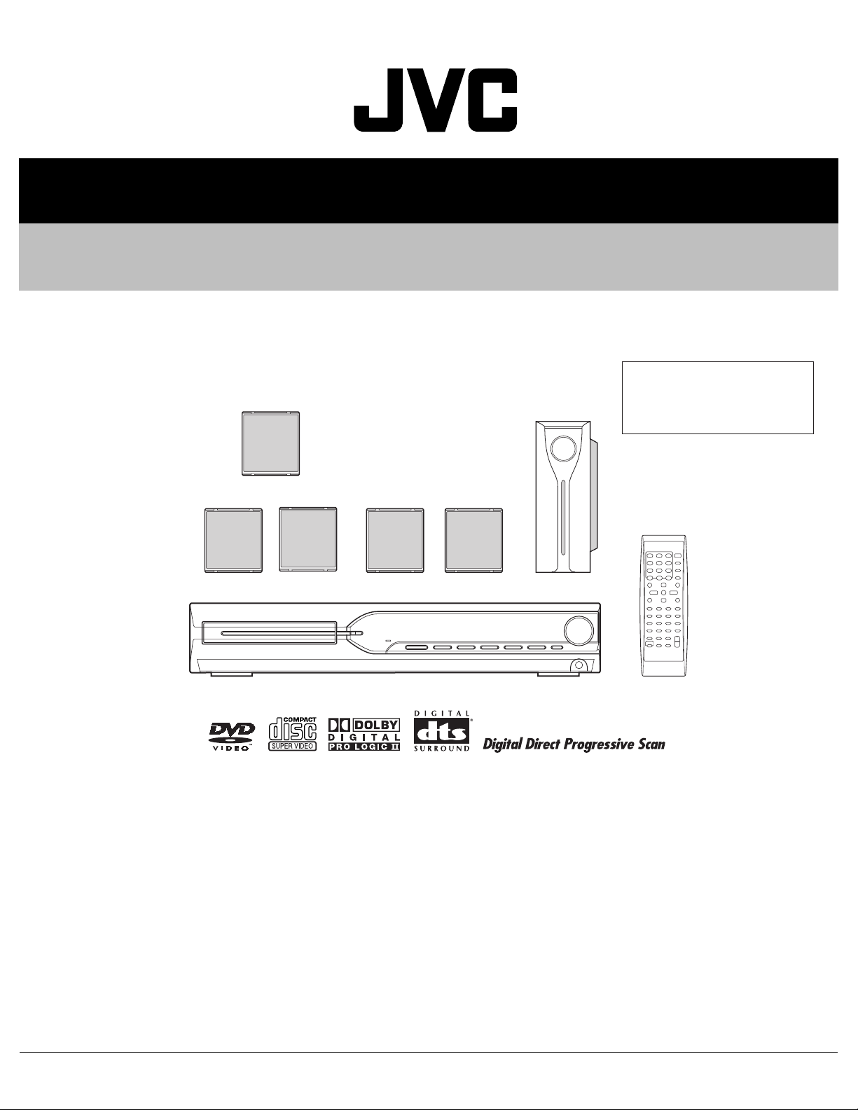
DVD DIGITAL THEATER SYSTEM
MB41320056
TH-S11
Area suffix
C ------------------------- Canada
(SP-THS11C)
(SP-THS11F)
Lead free solder used in the board (material : Sn-Ag-Cu, melting point : 219 Centigrade)
(SP-THS11S)
(XV-THS11)
(SP-WS11)
TABLE OF CONTENTS
1 PRECAUTION. . . . . . . . . . . . . . . . . . . . . . . . . . . . . . . . . . . . . . . . . . . . . . . . . . . . . . . . . . . . . . . . . . . . . . . . . 1-4
2 SPECIFIC SERVICE INSTRUCTIONS . . . . . . . . . . . . . . . . . . . . . . . . . . . . . . . . . . . . . . . . . . . . . . . . . . . . . . 1-7
3 DISASSEMBLY . . . . . . . . . . . . . . . . . . . . . . . . . . . . . . . . . . . . . . . . . . . . . . . . . . . . . . . . . . . . . . . . . . . . . . . 1-8
4 ADJUSTMENT . . . . . . . . . . . . . . . . . . . . . . . . . . . . . . . . . . . . . . . . . . . . . . . . . . . . . . . . . . . . . . . . . . . . . . . 1-23
5 TROUBLESHOOTING . . . . . . . . . . . . . . . . . . . . . . . . . . . . . . . . . . . . . . . . . . . . . . . . . . . . . . . . . . . . . . . . . 1-25
COPYRIGHT © 2005 Victor Company of Japan, Limited
No.MB413
2005/6
Page 2
SPECIFICATION
Center unit (XV-THS11)
Audio section Front/Center/Surround 33 W per channel, RMS at 6 Ω at 1 kHz,with 10% total harmonic dis-
tortion.
Subwoofer 40 W, RMS at 4 Ω at 100 Hz, with 10% total harmonic distortion.
Video section Video System NTSC
Horizontal Resolution 500 lines
Signal-to-Noise Ratio 64 dB
Video output level Composite 1.0 V(p-p)/75 Ω
S-video-Y 1.0 V(p-p)/75 Ω
S-video-C 0.286 V(p-p)/75 Ω
Component
(Interlace/Progressive)
Tuner section Tuning Range FM 87.5 MHz to 108.0 MHz
AM 530 kHz to 1 710 kHz
Speaker impedance Front/Center/Surround 6 Ω to 16 Ω
Subwoofer 4 Ω to 16 Ω
General Power Requirements AC 120 V , 60 Hz
Power Consumption 135 W (at operation)
Dimensions (W × H × D) 360 mm × 65 mm × 370 mm
Mass 5.3 kg
Y: 1.0 V(p-p)/75 Ω
PB/PR: 0.7 V(p-p)/75 C
1.3 W (in standby mode)
Front speakers (SP-THS11F)
Type 1-Way Bass-Reflex Type(Magnetically-shielded Type)
Speaker 8.0 cm cone × 1
Power Handling Capacity 33 W
Impedance 6 Ω
Frequency Range 90 Hz to 20 000 Hz
Sound Pressure Level 84 dB/W·m
Dimensions (W × H × D) 92 mm × 101 mm × 95 mm
Mass 0.58 kg each
Center speaker (SP-THS11C)
Type 1-Way Bass-Reflex Type(Magnetically-shielded Type)
Speaker 8.0 cm cone × 1
Power Handling Capacity 33 W
Impedance 6 Ω
Frequency Range 90 Hz to 20 000 Hz
Sound Pressure Level 85 dB/W·m
Dimensions (W × H × D) 92 mm × 101 mm × 95 mm
Mass 0.65 kg
1-2 (No.MB413)
Page 3
Surround speakers (SP-THS11S)
Type 1-Way Bass-Reflex Type
Speaker 8.0 cm cone × 1
Power Handling Capacity 33 W
Impedance 6 Ω
Frequency Range 90 Hz to 20 000 Hz
Sound Pressure Level 82 dB/W·m
Dimensions (W × H × D) 92 mm × 101 mm × 95 mm
Mass 0.56 kg each
Subwoofer (SP-WS11)
Type 1-Way Bass-Reflex Type
Speaker 15.0 cm cone × 1
Power Handling Capacity 40 W
Impedance 4 Ω
Frequency Range 40 Hz to 1 800 Hz
Sound Pressure Level 84 dB/W·m
Dimensions (W × H × D) 129 mm × 284 mm × 337 mm
Mass 3.0 kg
Designs & specifications are subject to change without notice.
(No.MB413)1-3
Page 4
SECTION 1
PRECAUTION
1.1 Safety Precautions
(1) This design of this product contains special hardware and
many circuits and components specially for safety purposes. For continued protection, no changes should be made
to the original design unless authorized in writing by the
manufacturer. Replacement parts must be identical to
those used in the original circuits. Services should be performed by qualified personnel only.
(2) Alterations of the design or circuitry of the product should
not be made. Any design alterations of the product should
not be made. Any design alterations or additions will void
the manufacturers warranty and will further relieve the
manufacture of responsibility for personal injury or property
damage resulting therefrom.
(3) Many electrical and mechanical parts in the products have
special safety-related characteristics. These characteristics are often not evident from visual inspection nor can the
protection afforded by them necessarily be obtained by using replacement components rated for higher voltage, wattage, etc. Replacement parts which have these special
safety characteristics are identified in the Parts List of Service Manual. Electrical components having such features
are identified by shading on the schematics and by ( ) on
the Parts List in the Service Manual. The use of a substitute
replacement which does not have the same safety characteristics as the recommended replacement parts shown in
the Parts List of Service Manual may create shock, fire, or
other hazards.
(4) The leads in the products are routed and dressed with ties,
clamps, tubings, barriers and the like to be separated from
live parts, high temperature parts, moving parts and/or
sharp edges for the prevention of electric shock and fire
hazard. When service is required, the original lead routing
and dress should be observed, and it should be confirmed
that they have been returned to normal, after reassembling.
(5) Leakage shock hazard testing
After reassembling the product, always perform an isolation check on the exposed metal parts of the product (antenna terminals, knobs, metal cabinet, screw heads,
headphone jack, control shafts, etc.) to be sure the product
is safe to operate without danger of electrical shock.Do not
use a line isolation transformer during this check.
• Plug the AC line cord directly into the AC outlet. Using a
"Leakage Current Tester", measure the leakage current
from each exposed metal parts of the cabinet, particularly any exposed metal part having a return path to the
chassis, to a known good earth ground. Any leakage current must not exceed 0.5mA AC (r.m.s.).
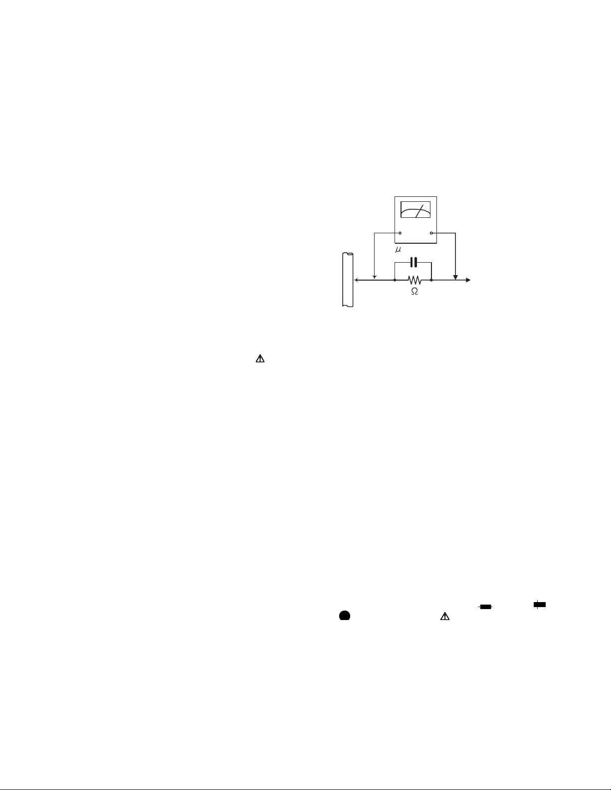
• Alternate check method
Plug the AC line cord directly into the AC outlet. Use an
AC voltmeter having, 1,000Ω per volt or more sensitivity
in the following manner. Connect a 1,500Ω 10W resistor
paralleled by a 0.15µF AC-type capacitor between an ex-
posed metal part and a known good earth ground.
Measure the AC voltage across the resistor with the AC
voltmeter.
Move the resistor connection to each exposed metal
part, particularly any exposed metal part having a return
path to the chassis, and measure the AC voltage across
the resistor. Now, reverse the plug in the AC outlet and
repeat each measurement. Voltage measured any must
not exceed 0.75 V AC (r.m.s.). This corresponds to 0.5
mA AC (r.m.s.).
AC VOLTMETER
(Having 1000
ohms/volts,
or more sensitivity)
0.15 F AC TYPE
Place this
probe on
1500 10W
Good earth ground
1.2 Warning
(1) This equipment has been designed and manufactured to
meet international safety standards.
(2) It is the legal responsibility of the repairer to ensure that
these safety standards are maintained.
(3) Repairs must be made in accordance with the relevant
safety standards.
(4) It is essential that safety critical components are replaced
by approved parts.
(5) If mains voltage selector is provided, check setting for local
voltage.
1.3 Caution
Burrs formed during molding may be left over on some parts
of the chassis.
Therefore, pay attention to such burrs in the case of preforming repair of this system.
1.4 Critical parts for safety
In regard with component parts appearing on the silk-screen
printed side (parts side) of the PWB diagrams, the parts that are
printed over with black such as the resistor ( ), diode ( )
and ICP ( ) or identified by the " " mark nearby are critical
for safety. When replacing them, be sure to use the parts of the
same type and rating as specified by the manufacturer.
(This regulation dose not Except the J and C version)
each exposed
metal part.
1-4 (No.MB413)
Page 5
1.5 Preventing static electricity
Electrostatic discharge (ESD), which occurs when static electricity stored in the body, fabric, etc. is discharged, can destroy the laser
diode in the traverse unit (optical pickup). Take care to prevent this when performing repairs.
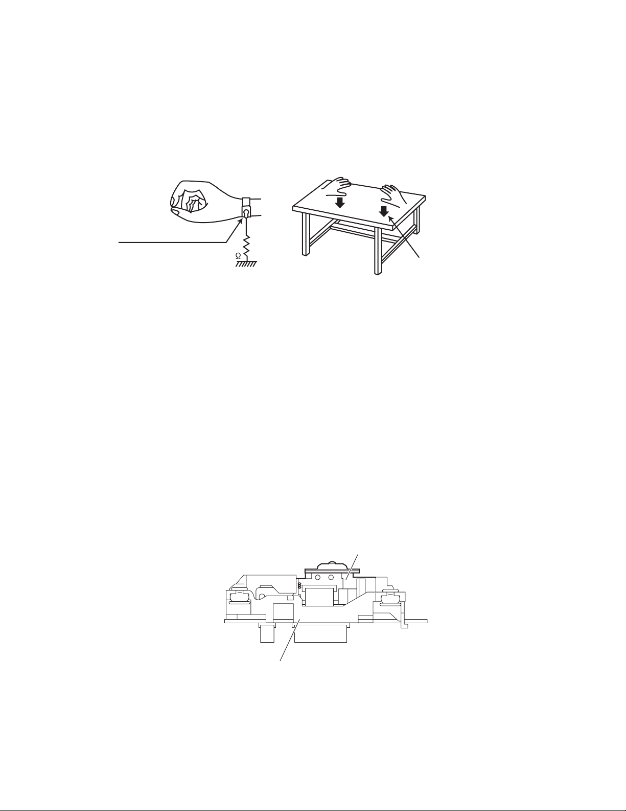
1.5.1 Grounding to prevent damage by static electricity
Static electricity in the work area can destroy the optical pickup (laser diode) in devices such as laser products.
Be careful to use proper grounding in the area where repairs are being performed.
(1) Ground the workbench
Ground the workbench by laying conductive material (such as a conductive sheet) or an iron plate over it before placing the
traverse unit (optical pickup) on it.
(2) Ground yourself
Use an anti-static wrist strap to release any static electricity built up in your body.
(caption)
Anti-static wrist strap
1M
Conductive material
(conductive sheet) or iron palate
(3) Handling the optical pickup
• In order to maintain quality during transport and before installation, both sides of the laser diode on the replacement optical
pickup are shorted. After replacement, return the shorted parts to their original condition.
(Refer to the text.)
• Do not use a tester to check the condition of the laser diode in the optical pickup. The tester's internal power source can easily
destroy the laser diode.
1.6 Handling the traverse unit (optical pickup)
(1) Do not subject the traverse unit (optical pickup) to strong shocks, as it is a sensitive, complex unit.
(2) Cut off the shorted part of the flexible cable using nippers, etc. after replacing the optical pickup. For specific details, refer to the
replacement procedure in the text. Remove the anti-static pin when replacing the traverse unit. Be careful not to take too long a
time when attaching it to the connector.
(3) Handle the flexible cable carefully as it may break when subjected to strong force.
(4) I t is not possible to adjust the semi-fixed resistor that adjusts the laser power. Do not turn it.
1.7 Attention when traverse unit is decomposed
*Please refer to "Disassembly method" in the text for the pickup unit.
• Apply solder to the short land sections before the flexible wire is disconnected from the connecto on the servo board. (If the flexible
wire is disconnected without applying solder, the pickup may be destroyed by static electricity.)
• In the assembly, be sure to remove solder from the short land sections after connecting the flexible wire.
DVD pickup
Traverse mechanism assembly
(No.MB413)1-5
Page 6
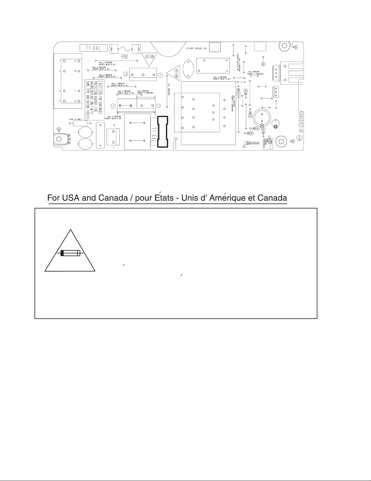
1.8 Importance administering point on the safety
EP950
Z953
B955
S950
R990
C960
B954
B953
C959
C961
CN950
Z952
C950
CN951
B952
B951
B974
CN952
B957
B956
T950
B950
3A-125V
F950
RY950
B968
B967
R952
B963
B973
B961
B970
D955
B964
D957
B959
B972
B971
B965
B969
D951
B960
D958
D956
FW953
HS950
Q950
Q951
B966
C951
C958
D959
Caution: For continued protection against risk of
fire, replace only with same type 3A/125V for F950.
This symbol specifies type of fast operating fuse.
Precaution: Pour eviter risques de feux, remplacez
le fusible de surete de F950 comme le meme type
que 3A/125V.
Ce sont des fusibles suretes qui functionnes rapide.
^
1-6 (No.MB413)
Page 7

SECTION 2
SPECIFIC SERVICE INSTRUCTIONS
This service manual does not describe SPECIFIC SERVICE INSTRUCTIONS.
(No.MB413)1-7
Page 8
SECTION 3
DISASSEMBLY
3.1 Main body section
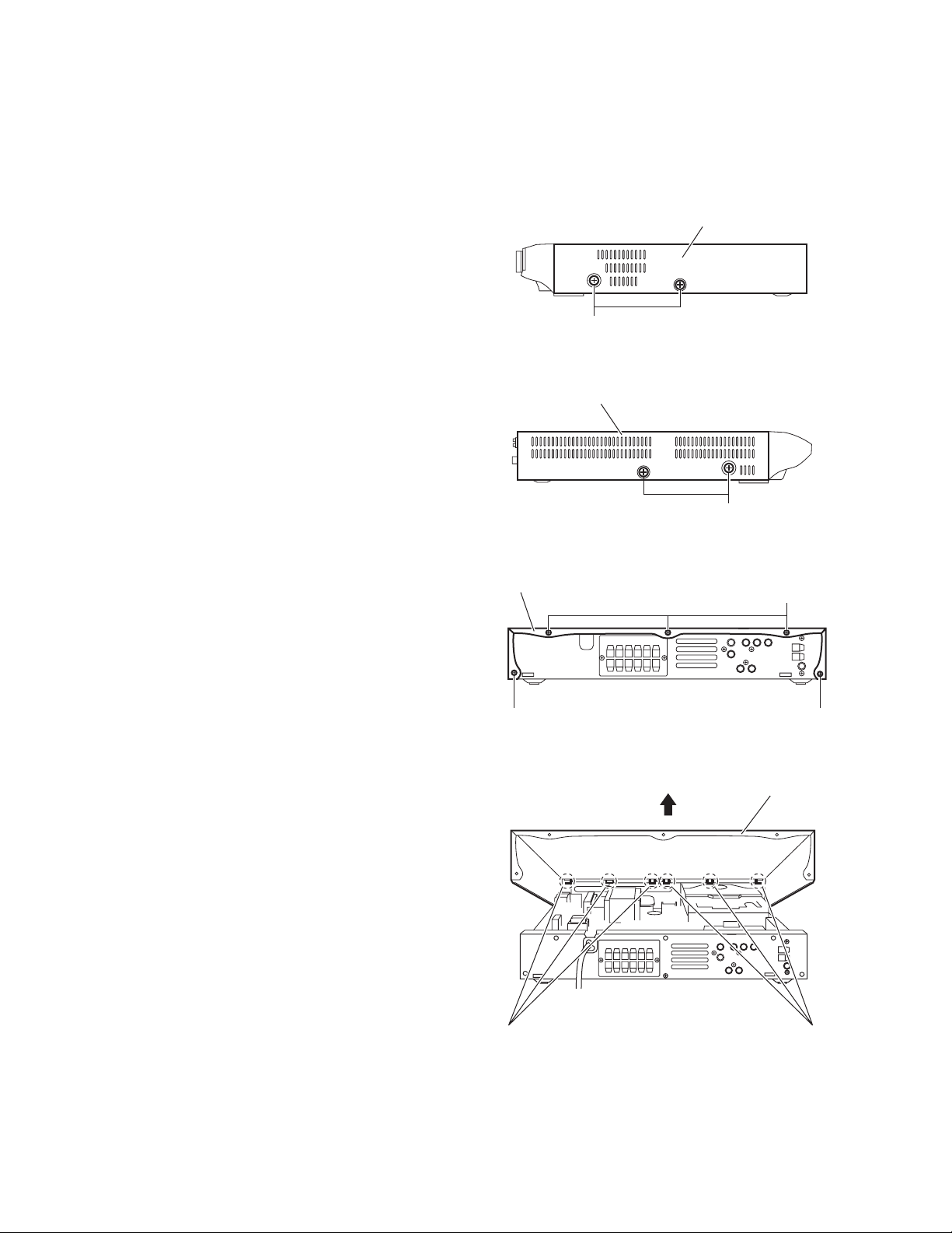
3.1.1 Removing the metal cover
(See Figs.1 to 4)
(1) From the both sides of the main body, remove the four
screws A attaching the metal cover. (See Figs.1 and 2.)
(2) From the back side of the main body, remove the five
screws B attaching the metal cover. (See Fig.3.)
(3) Lift the rear section of the metal cover in the direction of the
arrow while extending the lower sections of the metal cover, release the claws a using a longer screwdriver from the
inside as required. (See Fig.4.)
Note:
Do not damage any parts and boards inside the main body
when releasing the claws a using the longer screwdriver. (See
Fig.4.)
Metal cover
A
Fig.1
Metal cover
A
Fig.2
Metal cover
B
B B
Fig.3
Metal cover
1-8 (No.MB413)
a
Fig.4
a
Page 9
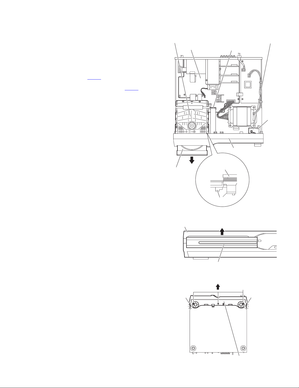
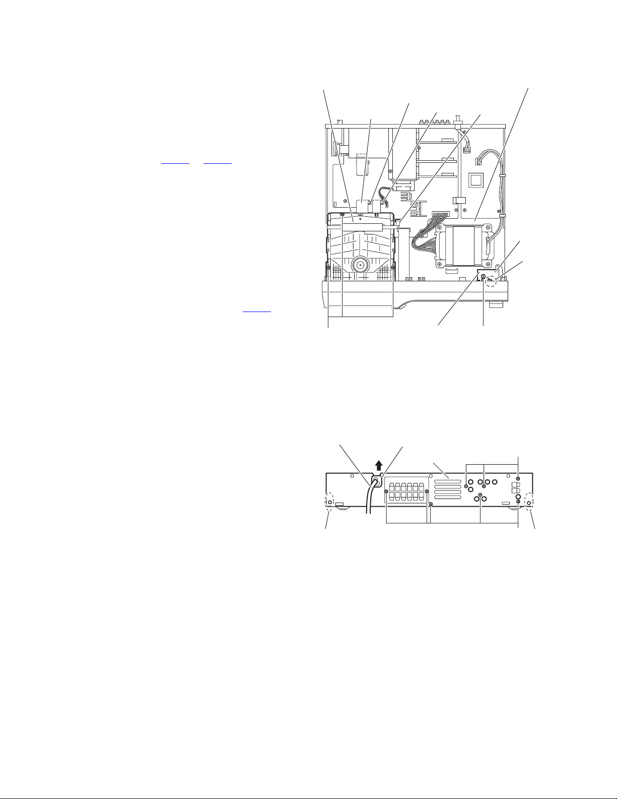
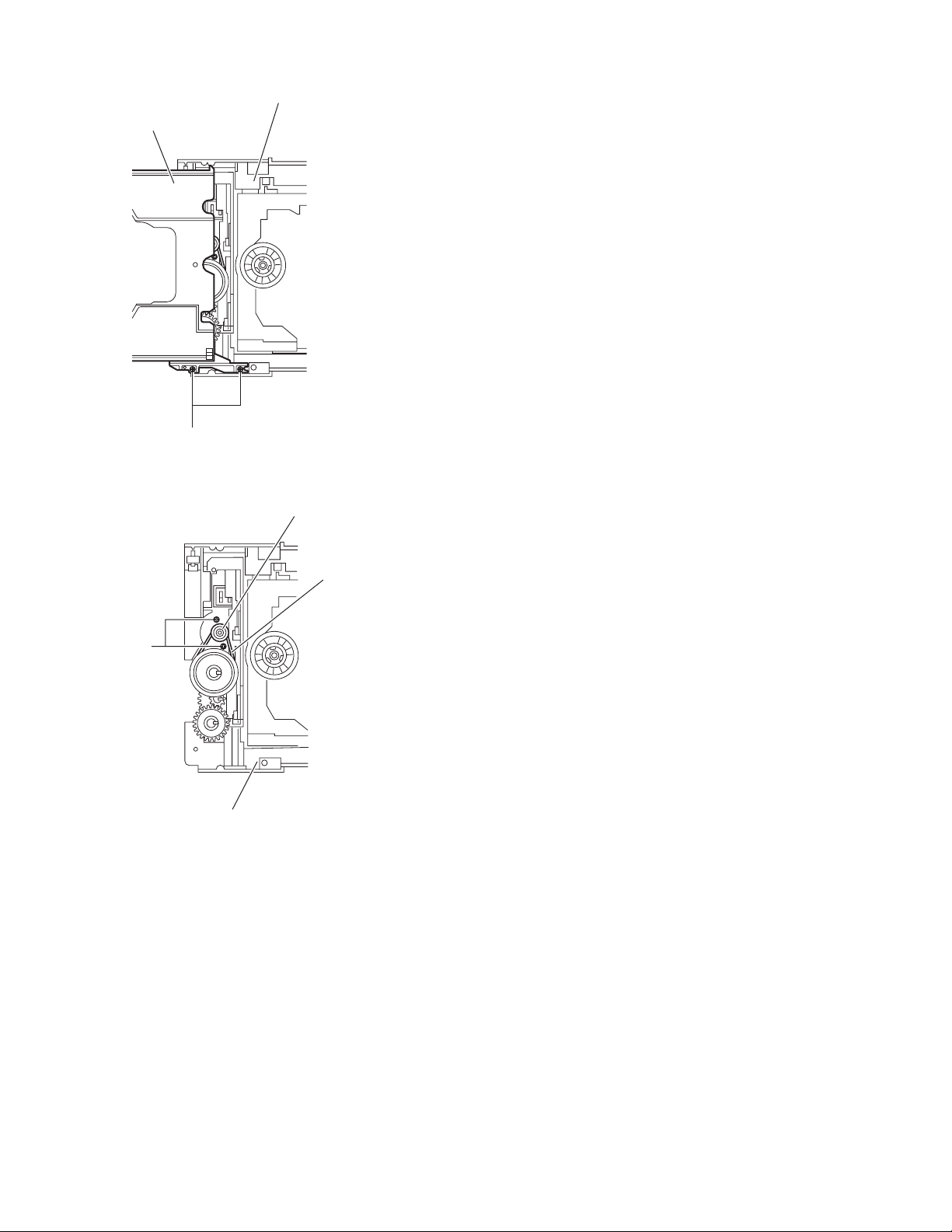
3.1.2 Removing the front panel assembly
(See Figs.5 to 7)
• Remove the metal cover.
(1) From the right side of the DVD mechanism assembly, push
the slide cam and pull the tray assembly out of the main
body in the direction of the arrow. (See Fig.5.)
(2) From the front side of the main body, remove the CD fitting
assembly from the tray assembly in the direction of the arrow and push in the tray assembly as before. (See Fig.6.)
(3) From the top side of the main body, disconnect the card
wire from the connector CN400
Fig.5.)
(4) Disconnect the card wire from the connector CN510
HP terminal board. (See Fig.5.)
(5) From the bottom side of the main body, remove the three
screws C attaching the front panel assembly. (See Fig.7.)
(6) From both sides and back side of the main body, remove
the front panel assembly in the direction of the arrow while
releasing the joints b. (See Fig.7.)
on the main board. (See
on the
DVD mechanism assembly
Main board
HP terminal board
CN400
CN510
Front panel assembly
Tray assembly
Front panel assembly
CD fitting assembly
b
DVD mechanism
assembly
Slide cam
Fig.5
Fig.6
C
b
Front panel assembly
Fig.7
(No.MB413)1-9
Page 10
3.1.3 Removing the DVD mechanism assembly
(See Figs.5,6 and 8)
• Remove the metal cover.
(1) From the right side of the DVD mechanism assembly, push
the slide cam and pull the tray assembly out of the main
body in the direction of the arrow. (See Fig.5.)
(2) From the front side of the main body, remove the CD fitting
from the tray assembly in the direction of the arrow and
push in the tray assembly as before. (See Fig.6.)
(3) From the top side of the main body, disconnect the card
wires from the connectors CN403
board. (See Fig.8.)
(4) Remove the three screws D attaching the DVD mechanism
assembly to the chassis base. (See Fig.8.)
3.1.4 Removing the HP terminal board
(See Fig.8)
• Remove the metal cover.
Reference:
Remove the front panel assembly as required. (See 3.1.2 "Removing the front panel assembly".)
(1) From the top side of the main body, remove the screw E at-
taching the HP terminal board to the chassis base.
(2) Disconnect the card wires from the connectors CN510
the HP terminal board. (See Fig.8.)
(3) Take out the HP terminal board from the main body.
Reference:
When attaching the HP terminal board, align the hole on the
HP terminal board to the projection c of the chassis base before attaching the screw E.
to CN405 on the main
on
DVD mechanism assembly
CN404
Card wires
D
HP terminal board
CN403
Fig.8
Chassis base
CN405
CN510
c
E
3.1.5 Removing the rear panel
(See Fig.9)
• Remove the metal cover.
(1) From the back side of the main body, remove the strain re-
lief attaching the power cord in the direction of the arrow.
(2) Remove the eight screws F attaching the rear panel to the
main body.
(3) Release the joints d, and remove the rear panel from the
main body.
Power cord
d d
Strain relief
Rear panel
Fig.9
F
F
1-10 (No.MB413)
Page 11
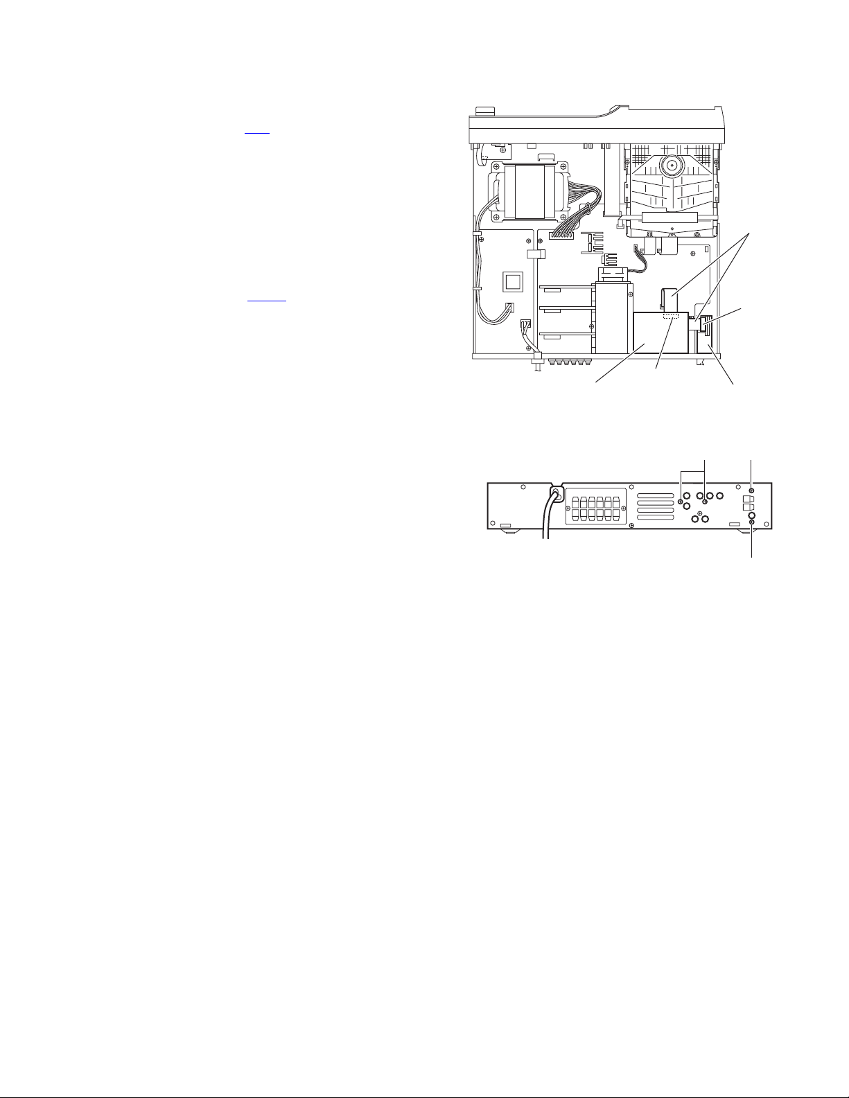
3.1.6 Removing the tuner assembly
(See Figs.10 and 11)
• Remove the metal cover.
(1) From the top side of the main body, disconnect the card
wire from the connector CN1
Fig.10.)
(2) From the back side of the main body, remove the two
screws G attaching the tuner assembly to the rear panel.
(See Fig.11.)
(3) Take out the tuner assembly from the main body.
3.1.7 Removing the video board
(See Figs.10 and 11)
• Remove the metal cover.
(1) From the top side of the main body, disconnect the card
wire from the connector CN350
Fig.10.)
(2) From the back side of the main body, remove the two
screws H attaching the video board to the rear panel. (See
Fig.11.)
(3) Take out the video board from the main body.
on the tuner assembly. (See
on the video board. (See
Card wires
CN1
CN350
Videol board Tuner assembly
Fig.10
Fig.11
H
G
G
(No.MB413)1-11
Page 12
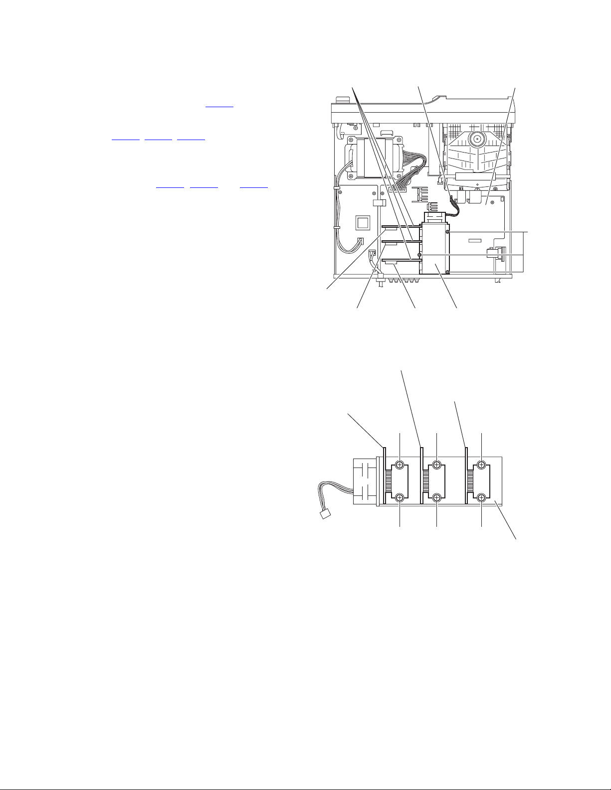
3.1.8 Removing the power amp.boards
(See Figs.12 and 13)
• Remove the metal cover and video board.
(1) From the top side of the main board, remove the three
screws J attaching the heat sink. (See Fig.12.)
(2) Disconnect the wire from the connector CN100
board. (See Fig.8.)
(3) Disconnect the each power amp.boards connecters from
the connectors CN271
(See Fig.12.)
Reference:
When attaching the heat sink with power amp.boards,
confirm the connectors CN281
ready lock before attaching the screws J.
(4) Take out the heat sink with power amp.boards from the
main board. (See Fig.12.)
(5) Remove the two screws K, two screws M and two screws
N attaching the heat sink. (See Fig.13.)
(6) Remove the each power amp.boards from the heat sink.
, CN276, CN281 on the main board.
, CN276 and CN271 al-
on the main
Power amp. board
CN100
Main board
J
CN281
CN276
Power amp. board
Power amp. board
(CEN & SW)
CN271
Fig.12
(SL & SR)
K
K
Fig.13
Heat sink
Heat sink
Power amp. board
(FL & FR)
M
M
N
N
Heat sink
1-12 (No.MB413)
Page 13
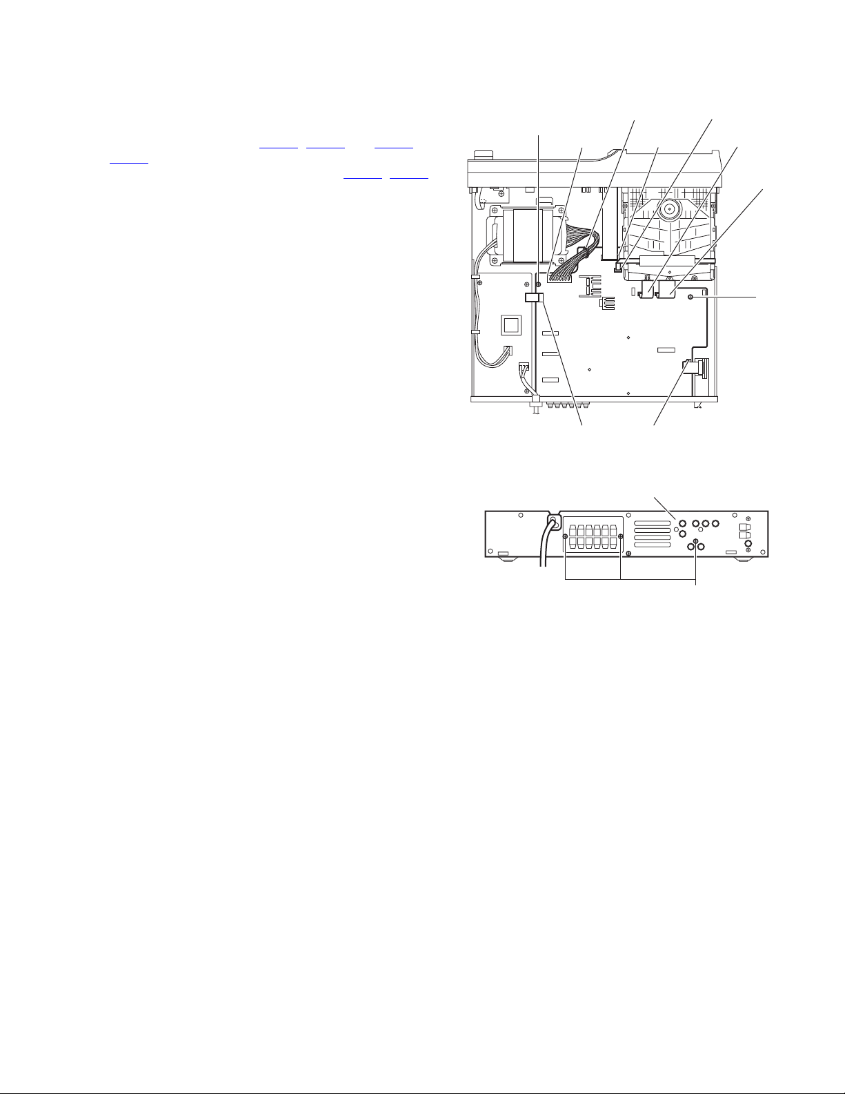
3.1.9 Removing the main board
(See Figs.14 and 15)
• Remove the metal cover, video board and heat sink with power
amp. boards.
(1) From the top side of the main body, disconnect the card
wires from the connectors CN400
, on the main board. (See Fig.14.)
CN405
(2) Disconnect the wires from the connectors CN102, CN101
on the main board. (See Fig.14.)
Reference:
After connecting the wires, fix the wires with the wire
clamp.
(3) Remove the two screws P attaching the main board to the
chassis base. (See Fig.14.)
(4) From the back side of the main body, remove the three
screws Q attaching the main board to the rear panel. (See
Fig.15.)
(5) Take out the main board from the main body.
, CN401 and CN403 to
Wire clamp
P
CN102 CN400
CN110 CN401
CN405
CN403
CN404
P
Fig.14
Rear panel
Fig.15
Q
(No.MB413)1-13
Page 14
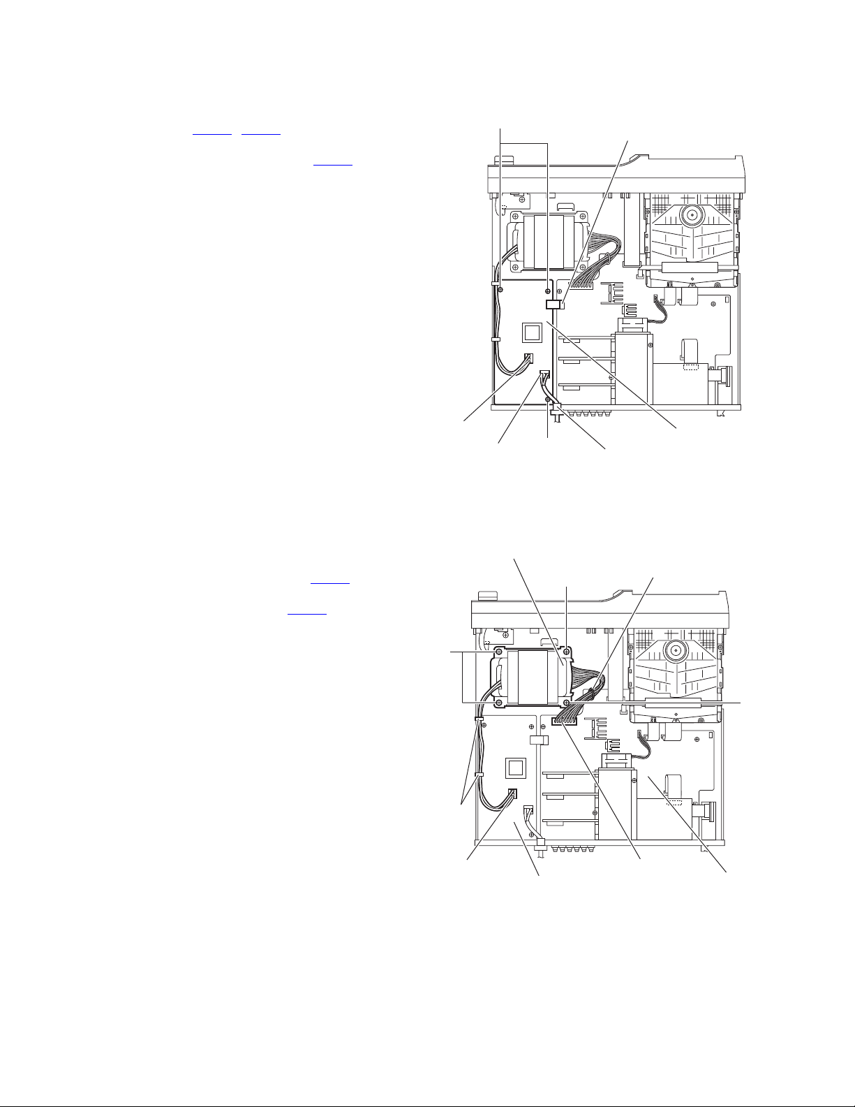
3.1.10 Removing the transformer board
(See Fig.16)
• Remove the metal cover.
(1) From the top side of the main body, disconnect the wires
from the connectors CN950, CN952 on the transformer
board.
(2) Disconnect the wires from the connectors CN101
main board.
(3) Remove the three screws R attaching the transformer
board.
(4) Take out the transformer board from the main body.
on the
R
CN101
3.1.11 Removing the power transformer
(See Fig.17)
• Remove the metal cover.
(1) From the top side of the main body, remove the tie bands
and wire clamp bundling the wires.
(2) Disconnect the wire from the connector CN952
transformer board.
(3) Disconnect the wire from the connector CN102 on the main
board.
Reference:
After connecting the wires to the connectors, bundle the
wires with the wire clamps and new tie bands as before.
(4) Remove the four screws S and take out the power trans-
former from the main body.
on the
CN952
CN950
Power transformer
S
Tie
bands
R
Fig.16
S
Transformer board
Power cord
Wire clamp
S
1-14 (No.MB413)
CN952
Transformer board
Fig.17
CN102
Main board
Page 15
3.1.12 Removing the front board
(See Figs.18 and 19)
• Remove the metal cover and front panel assembly.
(1) From the front side of the front panel assembly, pull out the
volume knob in the direction of the arrow. (See Fig.18.)
(2) From the inside of the front panel assembly, remove the six
screws T attaching the front board. (See Fig.19.)
(3) Take out the front board from the front panel assembly.
Volume knob
Front panel assembly
Fig.18
Front board
T
Front panel assembly
Fig.19
(No.MB413)1-15
Page 16
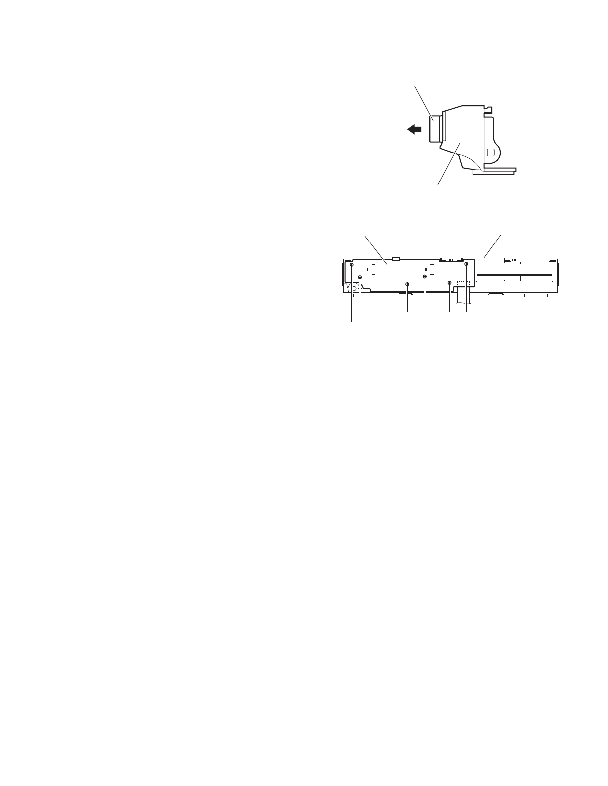
3.2 DVD mechanism section
• Remove the DVD mechanism assembly from the main body.
3.2.1 Removing the traverse mechanism assembly
(See Fig.1)
From the bottom side of the DVD mechanism assembly, remove
the four screws A attaching the traverse mechanism assembly
and take out the traverse mechanism assembly with the DVD
module board.
DVD mechanism assembly
Traverse mechanism assembly
AA
DVD module board
Fig.1
1-16 (No.MB413)
Page 17
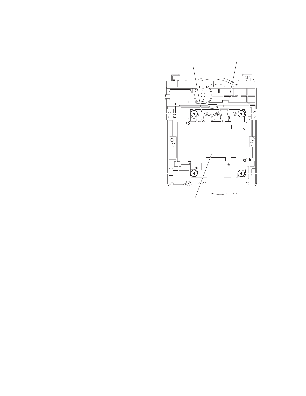
3.2.2 Removing the DVD module board
(See Figs.2 and 3)
• Remove the traverse mechanism assembly.
(1) From the side of the traverse mechanism assembly, solder
the short land sections a on the DVD pickup. (See Fig.2.)
(2) From the bottom side of the traverse mechanism assem-
bly, release the lock of the connector CN101
module board in the direction of the arrow and disconnect
the card wire. (See Fig.3.)
Caution:
• Solder the short land sections a on the DVD pickup before disconnecting the card wire from the connector
on the DVD module board. If the card wire is
CN101
disconnected without attaching solder, the DVD pickup may be destroyed by static electricity. (See Figs.2
and 3.)
• When attaching the DVD module board, be sure to remove solders from the short land sections a after connecting the card wire to the connector CN101
DVD module board. (See Figs.2 and 3.)
(3) Disconnect the card wire from the connector CN201
DVD module board. (See Fig.3.)
(4) Remove the two screws B attaching the DVD module
board. (See Fig.3.)
(5) Remove the DVD module board from the engagement sec-
tion b in an upward and remove the engagement section c
in the direction of the arrow. (See Fig.3.)
on the DVD
on the
on the
a
Traverse mechanism assembly
Card wire
B
DVD pickup
Fig.2
Card wire
CN101 CN201
b
c
DVD module board
B
Traverse mechanism assembly
Fig.3
(No.MB413)1-17
Page 18
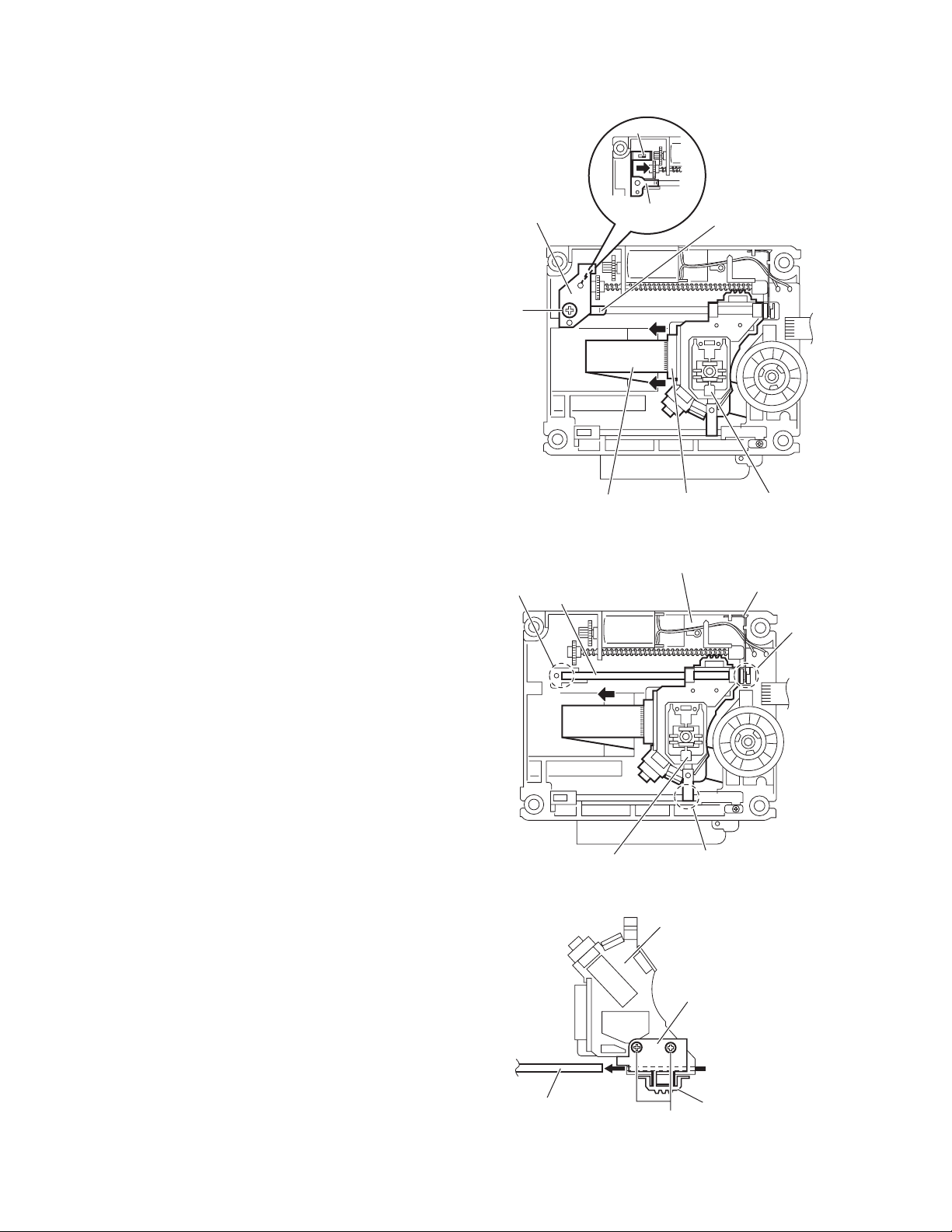
3.2.3 Removing the DVD pickup
(See Figs.2,4 to 6)
• Remove the traverse mechanism assembly.
(1) From the side of the traverse mechanism assembly, solder
the short land sections a on the DVD pickup. (See Fig.2.)
(2) Release the lock of the connector on the DVD pickup in the
direction of the arrow and disconnect the card wire. (See
Fig.4.)
Caution:
• Solder the short land sections a on the DVD pickup before disconnecting the card wire from the connector on
the DVD pickup. If the card wire is disconnected without attaching solder, the DVD pickup may be destroyed by static electricity. (See Figs.2 and 4.)
• When attaching the DVD pickup, be sure to remove
solders from the short land sections a after connecting
the card wire to the connector on the DVD pickup.
(See Figs.2 and 4.)
(3) Remove the screw C and remove the feed bracket from the
sections d. (See Fig.4.)
(4) Release the claw e of the thrust spring in the direction of
the arrow and remove the thrust spring. (See Fig.4.)
(5) Remove the guide shaft of the DVD pickup from the section
f on the traverse mechanism assembly and remove the
guide shaft from the section g while moving it in the direction of the arrow. (See Fig.5.)
(6) Remove the DVD pickup from the section h of the traverse
mechanism assembly and take out the DVD pickup with
the guide shaft. (See fig.5.)
(7) From the bottom side of the DVD pickup, remove the two
screws D attaching the rack arm and rack arm spring. (See
Fig.6.)
(8) Pull the guide shaft out of the DVD pickup. (See Fig.6.)
Feed bracket
C
Card wire
Traverse mechanism assembly
f
Guide shaft
e
Thrust spring
Connector
Fig.4
Thrust spring
DVD pickup
Torsion spring
g
1-18 (No.MB413)
DVD pickup
Guide shaft
h
Fig.5
DVD pickup
Rack arm
Rack arm spring
D
Fig.6
Page 19
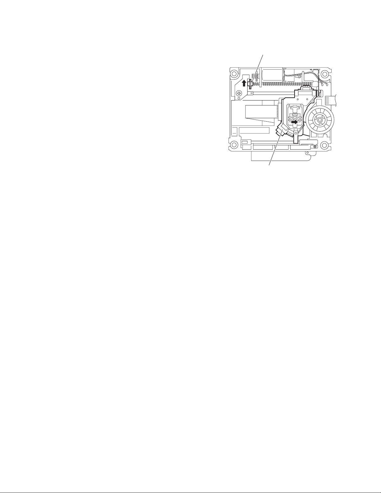
3.2.4 Attaching the DVD pickup
(See Figs.2,4 to 7)
• See "3.2.3 Removing the DVD pickup".
(1) Attach the guide shaft, rack arm and rack arm spring to the
DVD pickup. (See Fig.6.)
(2) Align the DVD pickup to the section h of the traverse mech-
anism assembly first, and set the both ends of the guide
shaft of the DVD pickup in the sections f and g of the
traverse mechanism assembly. (See Fig.5.)
Reference:
When attaching the guide shaft to the section g, attach it
under the rod spring. (See Fig.5.)
(3) Attach the feed bracket and thrust spring. (See Fig.4.)
(4) Remove solders from the short land sections a after con-
necting the card wire to the connector on the DVD pickup.
(See Figs.2 and 4.)
(5) Turn the screw shaft gear in the direction of the arrow 1 to
move the DVD pickup fully in the direction of the arrow 2.
(See Fig.7.)
Screw shaft gear
1
22
DVD pickup
Fig.7
(No.MB413)1-19
Page 20
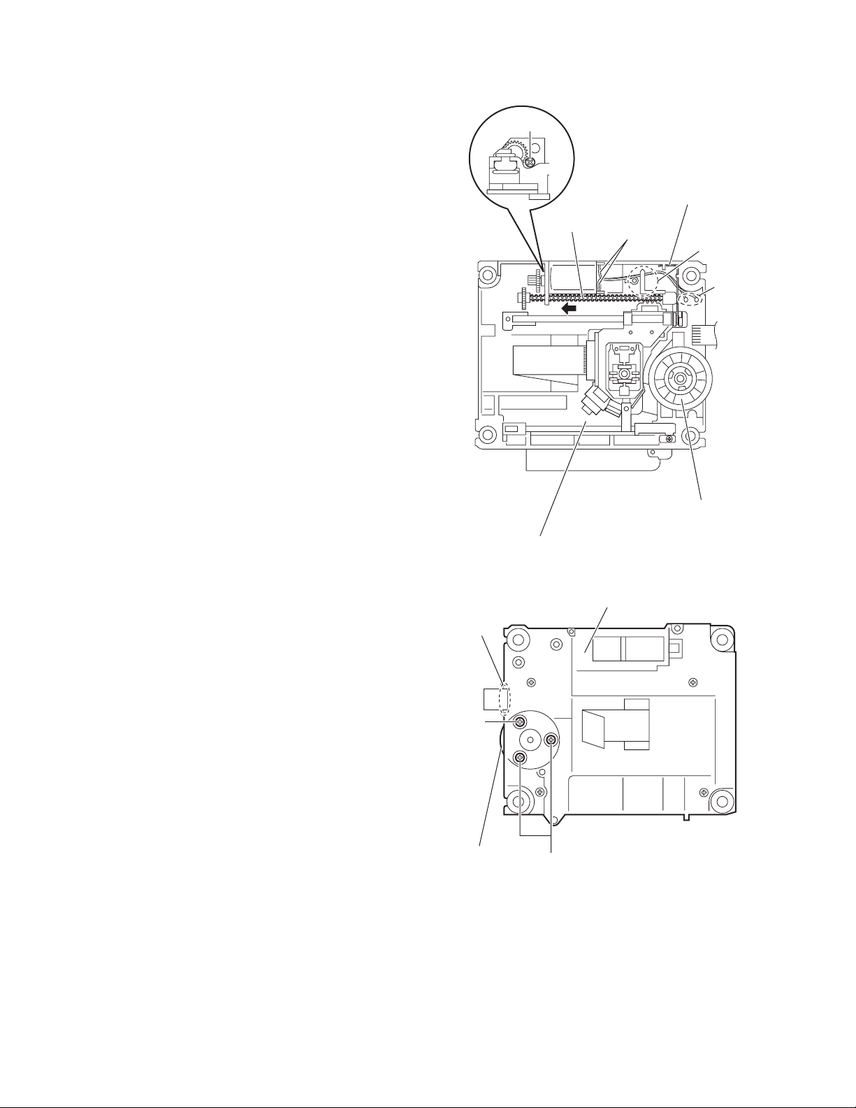
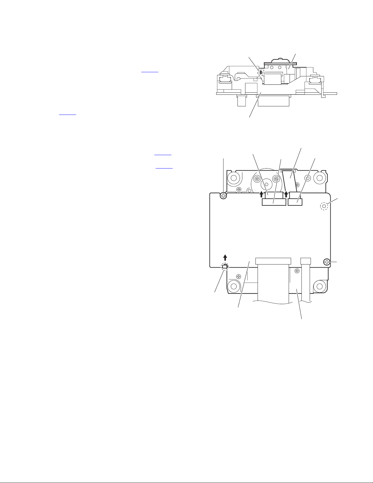
3.2.5 Removing the feed motor
(See Figs.4,8 and 9)
• Remove the traverse mechanism assembly.
(1) From the top side of the traverse mechanism assembly, re-
move the screw C and remove the feed bracket from the
sections d. (See Fig.4.)
(2) Release the claw e of the thrust spring in the direction of
the arrow and remove the thrust spring. (See Fig.4.)
(3) Remove the wires from the soldered section j on the spin-
dle motor board. (See Fig.8.)
Reference:
• When attaching the feed motor, pass the wire through
the section k on the traverse mechanism assembly.
(See Fig.8.)
• Pass the wire through the lower section of the rod
spring. (See Fig.8.)
(4) Remove the screw shaft in the direction of the arrow. (See
Fig.8.)
(5) From the side of the traverse mechanism assembly, re-
move the screw E attaching the feed motor. (See Fig.8.)
(6) Take out the feed motor from the traverse mechanism as-
sembly.
3.2.6 Removing the spindle motor board
(See Figs.8 and 9)
• Remove the traverse mechanism assembly and DVD module
board.
(1) From the top side of the traverse mechanism assembly, re-
move the wires from the soldered section j on the spindle
motor board. (See Fig.8.)
(2) From the bottom side of the traverse mechanism assem-
bly, remove the three screws F attaching the spindle motor
board. (See Fig.9.)
Reference:
• When attaching the spindle motor board, pass the wire
through the section m on the traverse mechanism assembly.
(See Fig.9.)
• After attaching the screws F, apply bond as before.
E
Screw shaft
Traverse mechanism assembly
Traverse mechanism assembly
m
Wires
Spindle motor board
Fig.8
Rod spring
k
j
1-20 (No.MB413)
F
Spindle motor
board
F
Fig.9
Page 21
3.2.7 Removing the DVD loading switch board
(See Fig.10.)
(1) From the bottom side of the DVD mechanism assembly, re-
move the wires from the soldered sections n on the DVD
loading switch board.
(2) Remove the screw G attaching the DVD loading switch
board.
(3) Lift the DVD loading switch board while pressing the claw
p of the DVD mechanism assembly in the direction of the
arrow and remove it from the section q.
Reference:
Pass the wires through the section r after attaching the DVD
loading switch board to the DVD mechanism assembly.
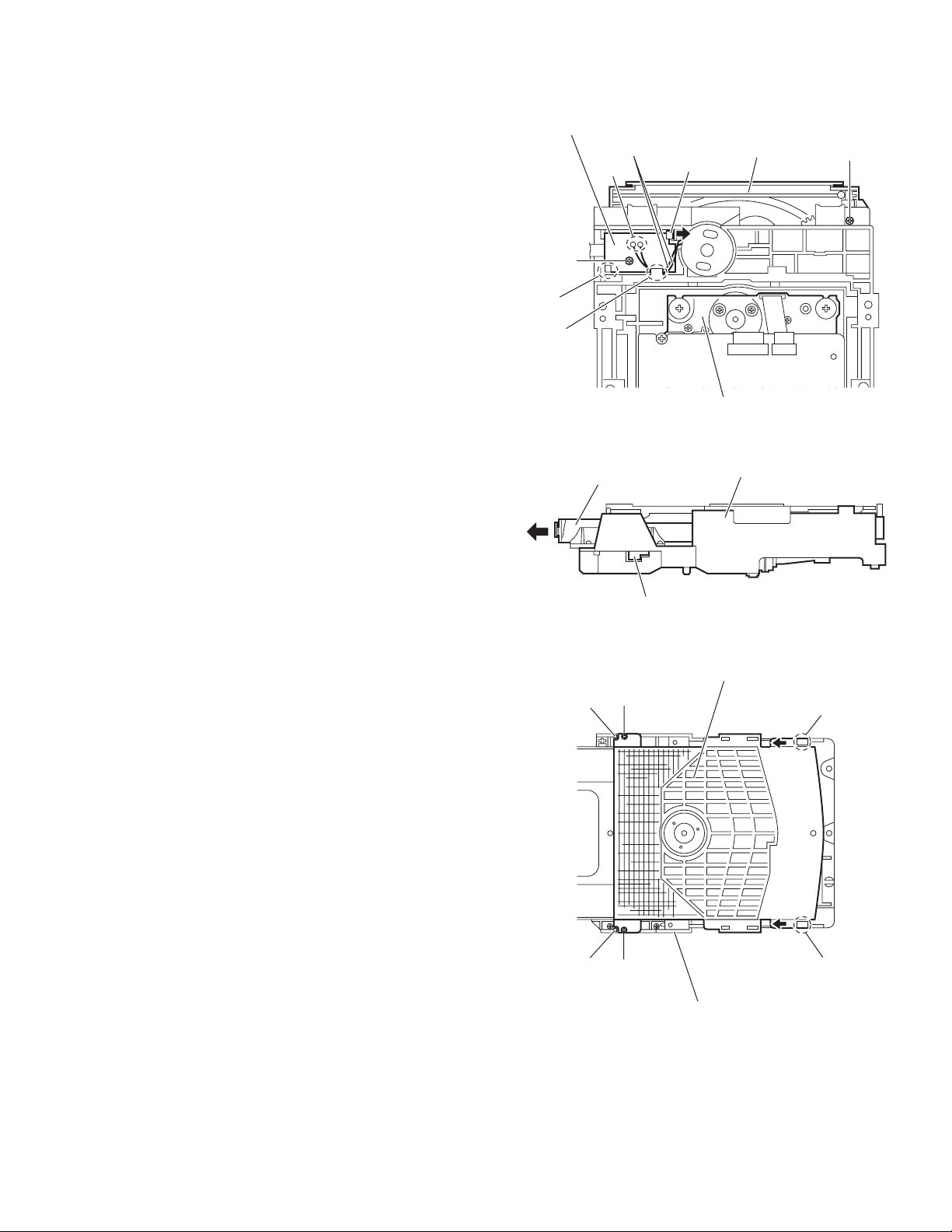
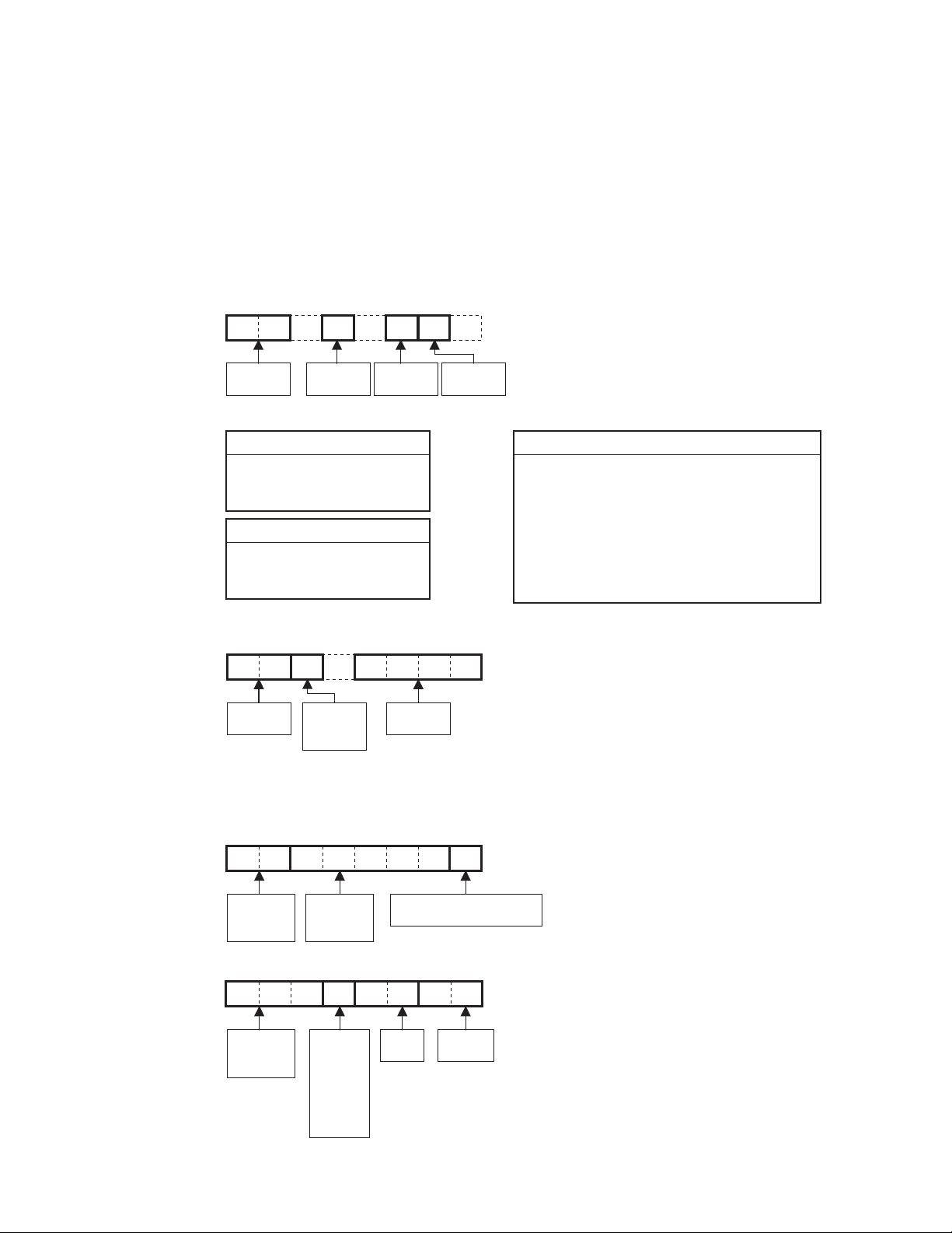
3.2.8 Removing the loading motor
(See Figs.10 to 14)
(1) From the bottom side of the DVD mechanism assembly, re-
move the wires from the soldered section n on the DVD
loading switch board. (See Fig.10.)
(2) Remove the screw H attaching the tray assembly. (See
Fig.10.)
(3) From the right side of the DVD mechanism assembly, push
the slide cam and pull the tray assembly out of the DVD
mechanism assembly in the direction of the arrow. (See
Fig.11.)
(4) From the top side of the DVD mechanism assembly, re-
move the two screws J attaching the clamper base. (See
Fig.12.)
(5) Lift the clamper base in an upward direction to remove it
from the engagement sections s and remove the engagement sections t in the direction of the arrow. (See Fig.12.)
(6) Remove the two screws K attaching the tray assembly and
take out the tray assembly from the DVD mechanism assembly. (See Fig.13.)
(7) Remove the belt from the motor pulley. (See Fig.14.)
Note:
Take care not to attach grease on the belt.
(8) Remove the two screws M attaching the loading motor to
the DVD mechanism assembly and take out the loading
motor from the bottom side of the DVD mechanism assembly. (See Fig.14.)
Reference:
Pass the wires through the section r after attaching the loading
motor to the DVD mechanism assembly. (See Fig.10.)
DVD loading switch board
Wires
n
G
q
r
DVD mechanism assembly
Tray assembly
Slide cam
J
s
DVD mechanism assembly
Clamper base
Tray assembly
p
Fig.10
Fig.11
H
t
s
t
J
DVD mechanism assembly
Fig.12
(No.MB413)1-21
Page 22
DVD mechanism assembly
Tray assembly
K
Fig.13
Motor pulley
M
DVD mechanism assembly
Fig.14
Belt
1-22 (No.MB413)
Page 23
SECTION 4
ADJUSTMENT
4.1 TH-S11 TEST MODE
This player has a TEST MODE for product QC, service or repair.
Contents as follows. If the DVD TRAY is not completely closed, supply AC power and press POWER ON to close the TRAY.
After confirm that the TRAY is completely closed go to standby.
Once LED lights up, pull off the power plug. Reinsert the AC power plug to the outlet while pressing,"POWER" and "STOP" button at
the front panel of the set.
TEST MODE has the 7 different steps. Press MENU key on the remote control to change the steps.
TEST MODE is canceled by the POWER key.
STEP 1:
RegionVersion
Version & Region explanation. Refer to next page.
Learn Status
Bit 0 - already learn DVD
Bit 1 - already learn CD
Bit 2 - already checked BCA area
Init Status
0x00 - normal init
0x01 - all init (above + FE)
0xFF - not yet init
STEP 2:
CPRM checksum (If Device key not input - FFFF)
STEP 3:
Sysyem
Version
STEP 4:
Indicator check mode. All FL segment light up.
STEP 5:
Mechanism check mode. In this mode player displays "CHECK".
STEP 6:
33E9K R
Rom
Correction
Version
Learn
Status
Unit
Init
Status
Region
0 - RF
1 - USA, Canada
2 - Europe, Middle East, Japan, South Africa
3 - S.Korea, Taiwan, HK, ASEAN
4 - Australia, NZ, Latin America
5 - Ex-Soviets, Indian sub-continent, Africa
6 - China
7 - Reserved
8 - International territory (airplanes, cruise ship, etc.)
Model type:
S11 or S33
STEP 7:
System micon version
S11B1935
Model
Name
Version and
tuner AM
step
Month:
1: Jan
2: Feb
:
:
A: Oct
B: Nov
Show R for RDS version or
blank for not RDS version
Day
Software
version
(No.MB413)1-23
Page 24

4.2 How to repair after carried out full-initialize
(1) Learning DVD
playback VT-501
(2) Learning CD
playback CTS-1000
(3) standby mode (push power key)
(4) Checking BCA
insert V-2805
test mode (press POWER and STOP button together during AC power plug in)
check mode (press menu key of remote controller)
BCA check (press +10 key of remote controller)
FL indication change "0000 0000" to "0000 0001" and Disc auto stop
(5) standby mode (push power key)
4.3 Rating Source, Region Code
Area Code
B/E/EN/EV AC230V 50Hz
EE
Video Signal
PAL
NTSC
J/C
UJ
US/UN
AC110,127,220,230-240V 50/60Hz
AC110,127,220,230-240V 50/60Hz
UB
UT
NTSC/PAL
AC110,127,220,230-240V 50/60Hz
UF/UFC
UW/UY
UX/UG
AC110,127,220,230-240V 50/60Hz
AC110,127,220,230-240V 50/60Hz
A
Rating Source
Rating Frequency
AC230V 50Hz
AC120V 60Hz
AC220V 50Hz
AC220V 50Hz
AC240V 50Hz
FL indicate of
Area Code in
Test mode
E
EE
JC
1U
3U
UB
UT
UF
4U
2U
4U
Region
Code
2
5
1
1
3
3
3
6
4
2
4
1-24 (No.MB413)
Page 25

SECTION 5
TROUBLESHOOTING
This service manual does not describe TROUBLESHOOTING.
(No.MB413)1-25
Page 26

Victor Company of Japan, Limited
AV & MULTIMEDIA COMPANY AUDIO/VIDEO SYSTEMS CATEGORY 10-1,1chome,Ohwatari-machi,Maebashi-city,371-8543,Japan
(No.MB413)
Printed in Japan
VPT
Page 27

SCHEMATIC DIAGRAMS
DVD DIGITAL THEATER SYSTEM
TH-S11
CD-ROM No.SML200506
Area suffix
C ------------------------- Canada
(SP-THS11C)
(SP-THS11F)
Lead free solder used in the board (material : Sn-Ag-Cu, melting point : 219 Centigrade)
Contents
Block diagram
Standard schematic diagrams
Printed circuit boards
(SP-THS11S)
(XV-THS11)
(SP-WS11)
2-1
2-3
2-21 to 25
COPYRIGHT 2005 Victor Company of Japan, Limited.
No.MB413SCH
2005/6
Page 28

In regard with component parts appearing on the silk-screen printed side (parts side) of the PWB diagrams, the
parts that are printed over with black such as the resistor ( ), diode ( ) and ICP ( ) or identified by the " "
mark nearby are critical for safety.
Page 29

< MEMO >
Page 30

CN405
CN401
CN403
CN404
Block diagram
TUNER
DVD pickup
mechanism
DVD traverse
mechanism
DVD servo contro section
A, B, C, D, E1+F1,E2+F2,E3+F3,E4+F4
CN101
RF+,RF-,PD(CD),PD(DVD)
LD(CD)
LD(DVD)
IC201
F+/T+/-
FM+/WOUT
VOUT
UOUT
CN201
COM
DRVER
Transformer section
Q951 to Q953
STBY 5V REG.
CN950
AC IN
Front section
HEAD
J5100
PHONE
Q101
Q104
SPDRV,TRSDRV
FODRV,TRDRV
/DRVMUTE
/SPMUTE,FG
IC510
EEPROM
T950
TRANS.
CN510
to
X301
27MHz
RY950
CN501
LPCO1
LPCO2
CDLDCUR
DVDLDCUR
TRVSW
SDA,SCL,WP
CN952
FW953
JS500
VOLME
IC501
REMOCON
HP-L,HP-R
HPDET
S2UDT,U2SDT,SCLK,SCS,UCS,CPURST,SCS
DAC1OUT,DAC2OUT,DAC3OUT,DAC4OUT,DAC5OUT
EXDT0 to 15,EXADT0 to 15
EXADR16 to 20
NEXCE, NEXOE,NEXWE
IC301
DV3.2
MA0 to 11
BA0,BA1,MCK
MDQ0 to 15
DQM0,DQM1
NCSM,NRAS
NCAS,NWE
DACCK,AIN,LRCK,ADCRST
AOUT0,DAC0CS,DCLK,DDADATA
AOUT1,DA CIS,AOUT2,DACPON,DAC2C8
T901
POWER
TRANS.
TO
FAN MOTOR
VOL1, VOL2
S5000 to S5007
PAN E L SW
D5000
STANDBY
IC500
FL DISPLAY
DI500
FL DISPLAY
STANDBYLED
S1 to S16
G1 to G12
IC505
SDRAM
CN102 CN101
S1 to S4,SCT,F+,F-
A+12V
STBY5V
POUTRELAY
Q1700
Q1701
CN100
FAN DRV.
KEY1
KEY2
REMOCON
DIDT
DICK
DICS
IC509
FLASH
FANO N
FANDET
FANLCK
CN500
ROM
CN400
CPURST
D1.2V
IC701 to IC704
IC302
D1.2V
REG.
S3.3V
P3.3V
IC705
A5V
A5V
REG.
DAC
S1
S2
DIODE
BRIDGE
S1
S2
Q1000
FL-VDISP
S3
S4
DIODE
BRIDGE
DIDT,DICK,DICS,STBY
KEY1,KEY2,VOL1,VOL2
REMOCON,HP-L,HP-R,HPDET
DVDPWR
IC305
3.1V
REG.
FAOUTL,FAOUTR
RAOUTL,RAOUTR
SWAOUT,CA OUT
DVD loader
section
+VH,-VH
-VDISP
IC110
A+12V
REG.
IC140
D10V
REG.
IC160
D5V
REG.
IC165
M5V
REG.
IC150
A+6V
REG.
IC15
A-6V
REG.
A+12V
D10V
A+6V
A-6V
CN701
CN702
CN1
D5V
M5V
2-1
Page 31

)
CN701
CN702
CN1
CN401
TUL,YUR
TUCE,TUDI,TUCK,TUDO
CN404
DAC1OUT to DAC5OUT
DVPWR,U2SDT,S2UDT,SCLK,SCS,UCS,CPURST
FAL
IC215
FAR
SAL
SAR
AMP.
SELECT
SELECT
CA
IC226
SWA
AMP.
SELECT
CN403
SEL3
SEL4
LM+
LM-
IC420
LOADING
TRAY+
TRY-
CN405
MOTOR
DRV.
OPEN,CLOSE
IC230
IC235
IC240
Micom / Audio section Video section
VOLDA
VOLCK
NOLMU
FLIN
FRIN
SLIN
SRIN
CIN
SWIN
TUL
TUR
SEL1
SEL2
CN407
IC211
IC212
AMP.
Q6000
Q6001
DAC1OUT to DAC5OUT
VDMU1
VDMU2
CN350
YCMIX
VDRGB
SEL1OUT
SEL2OUT
TUCE
TUDI
TUCK
TUDO
VDMU1,YCMIX
VDRGB,VDMU2
IC350
VIDEO DRV.
AUXL
TVL
AUXR
TVR
IC210
INPUT
SELECT
VIDEO OUT
(S-VIDEO/
COMPOSITE)
J3300J3200
VIDEO OUT
(COMPONENT
J2000
AUX IN
FLOUT,FROUT
IC411
RESET
IC410
SYSTEM
MICOM
2V
IC130
M9V
M9V
IC250
6CH
VOLUME
SLOUT,SROUT
COUT,SWOUT
J2850
SPEAKER
TERMINAL
REG.
FANDET
FNLCK
D5V
M5V
DIDT
DICK
DICS
DIRST
STBY
KEY1,KEY2
VOL1,VOL2
REMOCON
HPDET
FANO N
POUTR
DVD-POWER
AMPON
FLO
FRO
SLO
SRO
PRT3
PRT2
Audio section
CN270
CN271
FLOUT
FROUT
FLIN,FRIN
Audio section
CN275
CN276
SLOUT
SROUT
SLIN,SRIN
IC270
Power amp.
IC275
Power amp.
Audio section
CN280
CN281
IC265
HEADPHONE
AMP
FLO
FRO
CO
SWO
PRT1
SWOUT
COUT
SWIN,CIN
IC280
Power amp.
2-2
Page 32

Standard schematic diagrams
Transeformer section
FW953
QUM024-07DGZ4-E
CN101
(SHEET 2)
POUT-RELAY
D959
1N4003S-T5
STBY5V
A+12V
R958
3.3K
Q955
KTC3875/YG/-X
D960
C958
100/16
UDZS6.8B-X
KTC3875/YG/-X
3.3K
Q960
R961
1K
R962
R956
D953
UDZS5.6B-X
47K
1K
Q952
KTC3875/YG/-X
RY950
QSK0124-001
D950 C950
1SS355-X
0.01
C954
R963
1.2K
Q951
KTB772/Y/
Q953
KTC3875/YG/-X
R954
75K
3.3K
R955
R964
Q961
KTC3875/YG/-X
R953
10K
1000/25
1N4003S-T5
1N4003S-T5
QCZ9105-472
D955
1N4003S-T5
D956
1N4003S-T5
C951
D957
D958
D951
1N4003S-T5
QQT0253-012
T950
2-3
Parts are safety assurance parts.
When replacing those parts make
sure to use the specified one.
Page 33

T950
253-012
F950
3A-125V
QCZ9079-102
EP950
QNZ0136-001Z
C961
C959
QFZ9075-683
CN952
QGA7901C1-02
QCZ9079-102
R960C960
3.3M
CN950
QGA7901C1-02
T901
QQT0484-005
CN102
(SHEET 2)
SHEET 1
2-4
Page 34

1
1
A
A
Regulator section
CN102
QGA3901C1-08
F+
SCT
(SHEET 1)
F-
C900
0.1/100
D900
6A10E2
C903
0.1/100
D901
6A10E2
C901
0.1/100
D903
6A10E2
D902
6A10E2
C902
0.1/100
C904
4700/35
C905
4700/35
C1000
220/50
D1000
1N4003S-T5
D1002
1N4003S-T5
D1001 C1001
1N4003S-T5 220/63
R1001
3.3K
D1003
UDZS27B-X
R1000
2.2
Q1000
KTA1268/GL/-T
C1002
0.01
C1003
22/50
C912
0.1/50
D912
1N5401-TM
D911
C911
0.1/50
1N5401-TM
1N5401-TM
C910
0.1/50
D910
D913
1N5401-TM
C913
0.1/50
C914
6800/25
IC110
KIA7812API
C1100
100/25
C1101
R1400
10
R1401
10
R1402
10
R1403
10
0.01
IC140 IC
KIA278R10PI-U/P KI
R1600
10
R1601
10
R1602
10
R1603
10
0.01
C1300
220/16
C1301
C1401
1/16
C1400
100/25
IC130
KIA7809API
IC
KI
C1601
100/16
2-5
Parts are safety assurance parts.
When replacing those parts make
sure to use the specified one.
Page 35

To SHEET 4
IC160
KIA278R05PI
C1601
100/16
C1500
100/25
C1501
R1610
220
0.01
C1602
IC165
KIA7805API
4.7/50
C1004
C1652
0.01
C1651
100/16
0.01
UDZS7.5B-X
D1004
F+
F-
FANDET
SCT
POUTR
FNLCK
FANON
DVDPWR
CN101
QGD2504C1-04Z
POUTR
To SHEET 3
(SHEET 1)
DVDPWR
IC155IC150
KIA7906PI-U/PKIA7806API
C1552
C1550
C1551
0.01
100/35
100/16
FANSW
Q1701
KRC105S-X
Q1700
KTA1271/OY/-T
R1700
1.5k
FANON
R1703
1.5k
Q1702
KRC101S-X
C1700
10/16
C1701
R1701
10K
0.1
D1701
UDZS5.1B-X
10K
R1702
FANDET
FNLCK
CN100
QGA2501C1-03
SHEET 2
2-6
Page 36

0
1K
VS1
AVCIN
0
Micon section
To SHEET 4
To SHEET 2
To CN702
(SHEET 8)
To CN701
(SHEET 8)
CN403
QGF1036C1-15
CN404
QGF1036C1-25
B2924
K4101
Q4301
KRA102S-X
D4317
D4316
D4315
D4314
D4313
D4307
D4308
D4309
D4310
D4311
UDZS13B-X
UDZS13B-X
R4306
D4319
D4320
1N4003S-T5
1N4003S-T5
0
0
D4318
RB160L-60-X
R4158
330
UDZS10B-X
D4312
UDZS6.8B-X
D4306
R4305
10K
22K
C4111
0.01
UDZS6.8B-X
UDZS10B-X
R4169
10K
Q4303
KTC3875/YG/-X
Q4304
KRA102S-X
IC413
SN74AHCT08NS-X
R4301
10K
Q4305
KRC102S-X
R4159
220
D4321
Q4300
KRC102S-X
FANDET
POUTR
CA
SWA
SAL
SAR
LRMUTE
FAL
FAR
DAC3OUT
DAC2OUT
DAC1OUT
DAC4OUT
DAC5OUT
UCS
U2SDT
R4302
KEY1
KEY2
DIDT
DICS
DICK
S2UDT
U2SDT
SCLK
SCS
CPURST
UCS
DVDPWR
Q4302
22K
KTC3875/YG/-X
R4110
R4111
R4112
R4113
R4114
R4115
R4116
R4117
4.7K
5.6K
4.7K
R4156
R4157
R4155
FNLOK
FANON
CN406
QGF1205C1-06
0.01
C4200
R4303
10k
FAL
10K
10K
R4160
R4109
QAX0667-001Z
X4100
R4118
FAR
10K
R4108
1K
1K
1K
2.7K
330
100
2.2K
2.2K
220
C4201
SAL
10K
R4107
R4168
IC420
LB1641
0.1
SARCASWA
10K
R4106
10k
C4103
100/16
R4152
10K
R4104
10K
C4100
0.1/16
C4101
0.01
R4153
10K
10k
R4102
C4104
2.2K
R4154
15K
R4101
HPR
HPL
0.01
10K
R4100
R4119
R4120
R4131
4.7K
L4200
QQL244K-100Z
10K
10K
HPSW
R4121
REM
C4105
2.2/50
IC411
BD4826G-W
SEL4
220
RDSDA
SEL2
SEL3
C4102
0.01
R4122
220
RDSCK
R4123
VOL1
Q4100
KRC107S-X
D4100
C4109
220
R4132
SEL1
VDRGB
R4124
220
VOL2
22K
VDMU2
0.022
VOLCK
BLKCL
VDMU1
MN101C49GFR
TRAY-
TRAY+
C4110
VOLDA
YCMIX
0.001
IC410
VOLMU
SEL4
OPEN
10K
R4125
PRT1
SEL3
CLOSE
PRT2
SEL2
DVDPWR
R4126
VOL1
SEL1
R4165
10K
VOL2
PRT3
SCL
FNLOK
220
R4163
QGF12
AMPON
VOLCK
VOLMU
VOLDA
1K
1K
R4130
R4129
R4128
D4105
WP
SDA
VS3
R4133
10K
220
R4166
SDA
WP
SCL
FANON
R4127
10K
R41
R41
R41
10K
0.01
C4106
K4102
0
REM
KEY1
KEY2
DICK
DIDT
2-7
To CN1
(SHEET 9)
CN405
QGF1036C1-05
SCLK
DVDPWR
S2UDT
SCS
CPURST
CLOSE
OPEN
TRAY+
TRAY-
D4200
UDZS5.6B-X
C4203
0.01
C4202
100/16
To CN5
(SHEET
Page 37

AMPON
1K
R4130
SDA
VOLCK
QGF1205C1-11
VOLMU
VOLDA
1K
1K
R4129
R4128
D4105
VS3
VS1
CN401
LRMUTE
D4102
TUCE
TUDI
TUCK
R4150
R4149
R4148
R4147
R4140
R4164
TUDO
R4145
R4143
R4142
R4167
R4400
R4401
360
1K
1K
1K
1K
1K
220
220
1K
C4400
0.0082
R4403
220
1K
360
R4402
1K
220
FANDET
C4401
0.0082
TUCE
TUCK
TUDO
TUDI
RDSID
POUTR
PRT1
AMPON
PRT2
PRT3
RDS
RDSCK
RDS
RDSID
RDSDA
R4146
10K
R4141
10K
HPDET
0
K4000
X4500
QAX0868-001Z
C4509
330p
33p
C4503
10/16
C4508
33p
C4502
C4506
0.1
C4507
10/16
C4504
0.1
C4505
560p
IC450
LC72725M-X
R4127
10K
R4133
10K
K4102
REM
SDA
0
KEY1
WP
KEY2
SCL
DICK
R4166
R4135
R4136
R4137
0.01
C4106
220
FANON
DIDT
AVCIN
DICS
AVCOUT
330
330
330
STBY
HPDET
HPR
R4138
220
STBY
IC412
BR24L08F-W-X
HPL
CN400
QGF1036C1-19
HPSW
R4162
10K
VS3
VS1
DAC5OUT
DAC4OUT
DAC3OUT
DAC2OUT
DAC1OUT
BLKCL
VDMU1
VDMU2
YCMIX
VDRGB
AVCIN
AVCOUT
SCART-RIN
SCART-LIN
CN407
QGF1036C1-18
CN402
QGF1205C1-05
To SHEET 4
To CN350 (SHEET 5)
To CN500
(SHEET 6)
SHEET 3
2-8
Page 38

C
C
C
C
C
C
Audio section
W600
C2102
4.7/25
56p
R2260
33k
0.01
C2103
4.7/25
R2101
R2104
100K
C2154
0.1/16
C2155
0.1/16
330p
8.2K
IC215
RC4558D-X
270p
10k
C2258
0.1/16
C2259
0.1/16
IC226
RC4558D-X
WJZ0163-001A-E
KRA104S-X
KRA104S-X
IC211
RC4558D-X
R2105
R2103
100k
220K
R2121
R2122
330p
8.2K
C2261
10/50
IC240
CD4066BM-X
4.3K
RC4558D-X
R2156
2.7k
R2157
2.7k
R2258
1K
CIN
C2104
56p
R2106
12K
R2107
R2120
12K
C2117
C2116
IC211
0.1/16
4.3K
C2115
0.1/16
150
0.00470.0047
C2156C2157
R2352
1K
R2353
1K
0.01
C2260
R2400
33k
R2001
J2000
QNN0662-001
0
C2000
R2000
0.01/16
FAL
FAR
SAL
SAR
CA
SWA
TUL
TUR
HPL
HPR
To SHEET 3
HPSW
VOLDA
VOLMU
SMUTE
AMPON
FANSW
VOLCK
PRT1
PRT2
PRT3
SEL4
SEL3
SEL2
SEL1
51K
C2001
330p
C2002
330p
AUXL
TUL
AUXR
TUR
HPSW
FAL
FAR
SAL
SAR
CA
SWA
16K16K
R2002R2003
R2004
51K
AUXR
AUXL
SEL2
C2004
4.7/50
C2003
4.7/50
SEL1
Q2100
KRA104S-X
10K
R2100
R2102
150
IC210
CD4066BM-X
C2101C2100
0.010.01
IC215
RC4558D-X
C2150
47/16
R2150
2.7k
R2152
C2152
100k
R2154
R2153
R2151
2.7k
C2151
47/16
C2256
1/50
R2265
1k
R2262
100k
R2263
56K
C2263
R2266
1k
0.47/50
C2153
R2155
100k
C2257
R2259
IC226
RC4558D-X
R2261
3.3K
C2262
R2264
3K
0.01
C2400
C2401
To SHEET 2
R6001
Q6001
Q6000
2.2K
56p
22K
R6000
22K
R2108
10K
R2109
C2105
10k
4.7/25
Q2101
KTC3875/YG/-X 10K
Q2102
KTC3875/YG/-X
R2118
10K
C2114
0.1
C2113
R2119
10k
4.7/25
0.01
C2300
0.01
C2350
IC225
RC4558D-X
R2255
24K
R2251
1.5K
R2252
0.01
C2255
33k
IC225
RC4558D-X
IC212
RC4558D-X
C2107C2106
0.10.1
R2111
47K
R2110
100K
R2113
1K
C2108
56p
R2112
C2109
56p
R2114
1K
C2110
R2115
10k
R2117
47K
C2112
0.1
R2116
100K
RC4558D-X
R2301
22K
R2302
22K
R2354
220
R2250
1K
C2253
C2254
R2253
0.1/16
IC212
C2111
0.1/16
Q2103
KRA104S-X
Q2104
KRA104S-X
R2300
1K
IC230
CD4066BM-X
R2303
1K
C2301
0.01
R2355
220
R2350
1K
IC235
CD4066BM-X
R2351
1K
C2351
0.01
0.1
C2402
22K
R2401
R2403
NI
C2250
0.1/16
C2252
4.7/50
C2251
0.1/16
0.1
0.0047
R2254
1K
33k
C2650
2.2/50
56K
R2652
33K
R2651
C2651
2.2/50
SEL4
SEL3
C2501
SLIN
10/50
C2502
SRIN
FLIN
10/50
SWIN
FRIN
CIN
FRIN
FLIN
SLIN
SRIN
0.1
C2403
22K
R2402
PRT3
SWIN
R2501
R2502
3.3k
47k
R2503
C2503
47k
R2504
270p
C2504
R2506
C2506
1K
R2507
0.0068
C2508
1K
0.0068
SROUT
FROUT
FLOUT
0.33
C2755
C2853
0.33
C2705
4.7/1/4W
C2852
0.022
0.33
C2702
R2705
4.7/1/4W
C2851
0.022
RC4558D-X
56k
R2655
R2654 C2654 C2653
3.3k
10K
270p
R2500
C2500
R2505
10K
10/50
C2505
10/50
C2507
10/50
C2509
10/50
C2510
10/50
C2511
10/50
C2512 C2515
C2513
COUT
SWOUT
SLOUT
C2802 R2805
0.33
C2856
C2805
0.33
4.7/1/4W
C2855
0.33
R2753
C2752
4.7/1/4W
C2854
0.022
R2755
4.7/1/4W
0.022
R2703
RC4558D-X
IC265
33k
100/25 100/25
0.1
4.7/1/4W
R2803
0.022
C2662
0.1/16
IC265
150P
150P
0.022
R2653
C2657
R2656
C2655
IC250
BD3814FV-X
R2854
R2856
R2855
R2857
R2859
R2858
C2659
100/16
43K
33P
C2661
100/16
C2663
0.1/16
43K
33P
C2514
0.1
47K
47K
47K
47K
47K
47K
10K
R2861
Q2851
KRA101S-X
Q2852
KTC3875/YG/-X
2-9
C2904
1
C2905
C2906
1
C2907
0.022
C2908
0.022
C2909
0.022
J2850
QNB0189-001
1
C2910
0.022
C2911
0.022
C2912
0.022
Page 39

IC270
STK453-030A
R2712
1.2K
C2707
0.0022
HPL
C2521
C2520
C2519
C2518
C2517
C2516
10K
R2861
Q2852
KTC3875/YG/-X
R2658
R2659
22
22
R2663
2.2K
R2662
2.2K
C2527
C2526
C2525
C2524
C2523
C2522
3.3K
R2862
Q2853
KTC3875/YG/-X
HPR
QGB2510J1-10QGB2510J1-10QGB2510J1-10
CN270
CN271CN276CN281
AMPON
PRT3
R2660
FRO
2.2k
R2661
2.2k
VOLCK
VOLDA
VOLMU
10/50
SWO
SRO
10/50
SLO
10/50
CO
10/50
FRO
10/50
FLO
10/50
0.1
R2509
0.1
10K
0.1
R2508
0.1
10K
4700P
4700P
KRC102S-X
Q2850
100K
47/50
R2860
C2850
R2610
FLO
3.3k
IC266
IMX9-W
FLOUT
FROUT
FANSW
SLOUT
SROUT
AMPON
PRT2
SRO
R2606
SLO
3.3k
K2900
QQR0621-001Z
SWOUT
COUT
AMPON
PRT1
CO
R2602
SWO
3.3k
C2600
2.2/50
SMUTE
R2618
47K
KRA102S-X
Q2600
C2601
R2611
R2609
3.3K
2.2K
IMX9-W
IC262
R2608
2.2K
R2613
R2605
2.2K
IC261IC260
R2604
2.2K
R2601
2.2K
R2600
2.2K
1
C2602
47K
R2612
47K
D2870
R2870
10K
10K
D2871
R2871
C2870
47/25
CN275
R2607
3.3K
47K
R2614
IMX9-W
R2615
47K
CN280
R2603
3.3K
R2616
47K
IMX9-W
NI
47K
R2617
C2662
0.1/16
C2659
100/16
43K
33P
C2661
100/16
2663
/16
43K
33P
-X
2515
100/25
2514
0.1
47K
47K
47K
47K
47K
47K
Q2851
KRA101S-X
C2906
5
1
C2910
0.022
C2911
0.022
C2912
0.022
C2718
120/1/4W
0.1
R2700
C2703
1/50
R2701
C2719
0.1
4.7
R2704
L2700
C2768
0.1
C2769
0.1
4.7
R2754
L2750
C2818
0.1
C2819
0.1
0.39
4.7
R2804
L2800
R2706
56k
56k
C2704
7p
C2706
7p
0.39
4.7
0.39
L2701
R2702
5.6k
R2707
STK453-030A
IC275
120/1/4W
R2750
C2753
1/50
R2751
R2756
56k
56k
7p
C2754
C2756
7p
0.39
0.39
4.7
L2751
R2752
5.6k
R2757
STK453-030A
IC280
D2801 D2751 D2701
R2800
120/1/4W
C2803
1/50
R2801
56k
R2806
56k
7p
C2804
C2806
7p
0.39
4.7
L2801
R2802
5.6k
R2807
QGB2510K2-10
QGB2510K2-10
QGB2510K2-10
C2700
100/50
C2701
100/50
C2750
100/50
100/50
C2751
C2800
100/50
C2801
100/50
Parts are safety assurance parts.
UDZS15B-X
C2720C2770C2820
UDZS15B-X
UDZS15B-X
R2708
1.2K
56k
R2709
56k
R2710
220/35220/35220/35
C2757
R2758
1.2K
56k56k
R2759
R2760
C2807
R2808
1.2K
47K
R2809R2810
56k
R2715
C2709
0.0022
R2713
1.8k
R2711
C2714
2.2/50
10/16
10/16
C2708
C2710
R2762
1.2K
0.0022
C2759
0.0022
R2763
1.8k
1.8k
R2761
C2764
2.2/50
10/16
10/16
C2758
C2760
R2812
1.2K
0.0022
C2809
0.0022
R2813
1.5K
680
R2811
C2814
2.2/50
47/63
10/16
C2808
C2810
Q2700
100
KTA1504/YG/-X
R2721
100
1.8k
C2711
R2714
2.2/50
C2712
470p
C2713
470p
R2717
1k
R2765
100
R2771
100
R2764
C2761
2.2/50
C2762
470p
C2763
470p
R2767
1k
R2815
100
R2821
100
C2811
0.47/50
C2812
470p
C2813
470p
R2817
1k
R2720
27K
R2716
10K
R2722
1K
1k
1
C2717
D2700
UDZS5.1B-X
Q2750
KTA1504/YG/-X
R2770
27K
R2766
10K
1K
R2772
1k
1
C2767
D2750
UDZS5.1B-X
Q2800
KTA1504/YG/-X
R2820
27K
R2816
10K
R2822
R2814
1K
1k
1
C2817
D2800
UDZS5.1B-X
When replacing those parts make
sure to use the specified one.
SHEET 4
2-10
Page 40

Video section
To CN407
(SHEET 3)
CN350
QGF1036F1-18
A5V
VDMU1
VDMU2
YCMIX
VDRGB
750
R3500
750
R3502
180180 750
R3504R3506 R3508
270
R3501
270270 200200
R3503R3509 R3505R3507
R3510
L3500
QQL25CK-221Z
VDMU1
YCMIX
VDRGB
NI
C3500
470/10
C3501
0.1/16
C3502
1/10
C3503
47/16
C3504
1/6.3
C3505
22/16
C3506
1/10
IC350
BH7868FS-X
VDMU2
C3507
1/10
C3508
1/10
C3509
1/10
2-11
Page 41

C3513
470/6.3
C3512
470/6.3
C3511
470/6.3
C3200
470/6.3
C3201
0.01/16
R3300
75
R3301
75
R3302
75
R3200
75
R3201
75
R3202C3510
J3300
QNN0572-001
NI
NININI
R3303
C3300C3301C3302
J3300
NINI
R3304R3305
75470/6.3
QNN0572-001
J3300
QNN0572-001
J3200
QNN0557-002
SHEET 5
2-12
Page 42

5
5
K
5
0
0
0
1
Front section
S5
S6
S7
S2
S8
S3
S4
S15
S16
S13
S14
S12
S11
S10
C5004
0.01
G11
G10
G12
G12
G11
S16
S15
G10G9G8G7G6G5G4G3G2
DI500
QLF0156-001
S14S9S13S1S12
S11
G1
S10
C5006
0.01
G9
G8
G7
G6
G5
G4
G3
G2
G1
J5100
QNS0170-001
IC500
PT6315
82k
R5002
DIDT
R5100
1k
DICK
DICS
C5103C5104 C5102
0.10.022 0.1
C5101
S9
S8
S7
S6
S5
S4
S3
S2
S1
K
QQR
K
QQR
QQR
R
C5100
0.1
0.01
2-13
Page 43

JS500
QSW1059-001
C5001
0.01
0.01
C5000
R5009R5010
2.4k3.9k
S5001S5002
R5014 R5015
3.9k 6.8k
VOL2
R5008R5011
9106.8k
S5000
QSW1121-001Z
VOL1
VOL2
REM
KEY1
KEY2
DICK
DIDT
DICS
CN500
QGF1036F1-19
To CN400
(SHEET 3)
S9
S8
S7
S6
S5
S4
S3
S2
S1
C5002
C5005
0.01
47/10
IC501
GP1UM271XKVF
C5011
1/16
REM
S5003
QSW1121-001Z
R5012 R5013
910 2.4k
R5006
D5000
SLR-342VC3F
VOL1
220
Q5000
KRC102S-X
QSW1121-001ZQSW1121-001Z
C5100
0.01
K5100
QQR0601-001Z
QQR0601-001Z
K5102
QQR0601-001Z
R5101
1k
S5004 S5005 S5006
CN501CN510K5101
QGF1210G1-04QGF1205F1-04
QSW1121-001Z QSW1121-001Z QSW1121-001Z
S5007
QSW1121-001Z
SHEET 6
2-14
Page 44

5
DVD servo control section (1/2)
TP115
CN101
CN201
TP291
TP292
C102
0.1
C101
C103
C104
TP101
QGF0523F1-25W
TP208
TP204
QGF1016F2-08W
C290
R290
NI
TP118
TP122
TP116
TP117
TP123
TP121
TP120
TP119
TP124
0.1
0.1
C107
0.1
0.1
F+
F-
T+
TP106
TP107
TP109
T-
R126
100
TP104
TP103
TP102
TP105
TP207
FM+
FM-
WOUT
VOUT
UOUT
COM
TP202
TP203
TP201
NI
470
R201
1k
R202
TP205 TP206
C774
DGND
TP108
TP114
TP113
VREFH
C
D
E3+F3
E4+F4
E1+F1
A
B
E2+F2
RF+
RF-
R101
100
R102
100
TP111
TP110
TP112
UN2119-X
Q105
C263
NI
100/16
MA4
MA3
MA2
MA
C300
0.1
C372
0.1
LPC2
LPC1
CDLDCUR
NI
NI
C109
C771
DGND
COM
C260
C261
C262
0.1
C217
R113
18
R112
C110
KTA1001/Y/-X
2SC4617/R/-X
5.6K
R111
NI
FM+
WOUT
VOUT
UOUT
0.022
0.022
0.022M9V
NI
0.39
R251
R252
C203
0.01
LPCO2
DVDLDCUR
C106
C108
22/6.3
2.2
R116
R114
R115
R117
F-
FM-
IC201
LA6502-X
R105
18
R104
4.3K4.3K
NI
470
R118
330
T+
F+
T-
220p
C201
C202
R106
Q101Q103
KTA1001/Y/-X
2SC4617/R/-X
5.6K
R103
M5V
C777
220p
DGND
C205
270p
C264
NI
R206
30k
C204
0.1
S5V
LPCO1
1
R125
NI
C776
22/6.3
2.2
R108
R107
1k1K
Q102Q104
R109
NI
R204
27k
R219
DGND
NI
470
R110
4.3K
R127
AD4
R128
C105
330
5.6K
47/6.3
/HFMON
R356
R361
R363
TRVSW
R355
TP227
NI
R208
18k
1
C371
R354
TRDRV
R384
1k
1k
R385
C373
NI
C315
0.1
EXADT0
NEXCE
NEXOE
C307
0.1
EXDT0
EXDT8
EXDT1
EXDT9
EXDT2
EXDT10
EXDT3
EXDT11
EXDT4
EXDT12
EXDT5
C374
NI
EXDT13
EXDT6
EXDT14
EXDT7
EXDT15
EXADR16
NI
EXADT15
NI
EXADT14
NI
C329
0.1
EXADT13
EXADT12
EXADT11
EXADT10
EXADT9
EXADT8
C375
0.1
EXADR19
NEXWE
EXADR18
NI
EXADR17
NI
EXADT7
EXADT6
EXADT5
EXADT4
EXADT3
EXADT2
EXADT1
EXADR20
330
330
10k
R319
R325
R326
100
100
100
1k
330
R353
R383
R310
R316
R324
0.1
C308
2-15
0.0082
0.015
0.015
R214
6.8k
TRSDRV
0.47
C257
C251
R213
C211
0.022
10k
C210
10k
TP226
24k
R220
C258
C259
1
R207
47k
C206
150p
27k
TP231
R205
NI
R254
/SPMUTE
FODRV
/DRVMUTE
FG
0.1
C564
R541
IC510
BR24L16FV-W-X
NI
R542
47k
S2UDT
SCS
UCS
UCLK
U2SDT
LRMUTE
DDATA
DCLK
DAC0CS
10k
0.1
NI
R257
NI
R255
TP220
MGND
SPDRV
R221
C256
R259
TP221
R215
NI
Page 45

R316
1k
LRMUTE
MA4
MA1
MA3
MA2
MA5
MA6
MA0
MA7
MA8
MA9
BA0
BA1
MA10
C300
0.1
C383
0.1
MA11
0.1
C306
MCK
NRAS
NCSM
R303
C386
0.1
IC301
MN2DS0009VP
MDQ7
MDQ8
DQM0
DQM1
22
C379
0.1
C378
NI
NWE
NCAS
MDQ3
MDQ4
MDQ5
MDQ9
MDQ6
MDQ10
MDQ11
MDQ12
MDQ0
MDQ1
MDQ2
MDQ15
MDQ14
MDQ13
C377
0.1
0.1
C305
R327
330
R330
NI
R331
330
P3.3V
C302
47/4
R332
R318
TP325
TP320
C376
0.1
TP328
TP329
TP330
TP331
TP332
TP333
TP334
TP335
NI
C311
TP338
C313
R351
R352
C339
10/6.3
1
C356
30k
R340
C341
1
D1.2V
IC302
IC302
R362
R357
R364
R360
R359
R358
R365
R367
R366
R345
C325
C326
0.1
0.1
C359
DGND
0.1
2.4K
TP301
R346
NAD0025-103X
MM1701CH-X
1
C328
0.01
DACPDN
ADCRST
DAC1CS
DAC2CS
330
AOUT0
220
NI
AOUT1
220
AOUT2
220
220
BCK
NI
220
LRCK
NI
220
DACCK
12p
10P
DAC5OUT
DAC4OUT
R341
5.1k
DAC1OUT
DAC2OUT
DAC3OUT
C354
C353
TP300
R347
TH301
560p
560p
20k
FODRV
22k
TRDRV
AD4
CDLDCUR
TP381
R392
10k
TP321
C303
47/6.3
330
NI
0.1
680
1M
X301
NAX0741-001X
C318
R342
C316
C312
C393
0.01
SWMUTE
DATAM
BCKM
LRCKM
D2V
1
NI
C336
C304
DVDPWR
TP305
TP303
RX
TX
CPURST
1k
R306
R307
1k
NI
D301
CN301
To SHEET 8
NI
DVDLDCUR
S3.3V
0.1
100
100
100
R310
R383
R353
TP304
0.01
750
R350
C350
470
R375
AIN
UCS
UCLK
U2SDT
S2UDT
SCS
TRVSW
TP326
0.1
C334
0.1
100k
R309
NI
R371
1k
1kNI1k
C310
R376
R377
R374
10k
R308
/HFMON
/DRVMUTE
/SPMUTE
FG
CPURST
R373
SPDRV
10k
R372
TRSDRV
NI
NI
NI
TP308
TP309
R323
R321
R320
R322
C309
0.1
TP323TP324
10k
C351
0.01
C352
0.015
INDEX
TRACK
COPY
DEMP
0.1
0.033
C331
TP306
C338
C333
C332
TP307
0.1
C335
0.1
0.1
0.0056
C337
TP314
TP315
0.018
C348
C347
150
150
0.1
C330
R349
R348
RF-
RF+
C319
0.1
0.1
0.1
0.1
0.1
0.1
C314
C320
C321
C322
C323
0.1
C349
LPCO1
LPC1
TP337
C324
1
C340
1
0
0
150
150
150
150
0
0
NI
R337
R336
R335
R334
R339
R338
R393
R394
E2+F2
VREFH
LPCO2
LPC2
E1+F1
A
E3+F3
E4+F4CD
B
C770
DGND
K352
C301
NQR0502-001X
220/4
NI
C772
DGND
SHEET 7
2-16
Page 46

A
O
O
O
A
C
R
A
A
A
DVD servo control section (2/2)
IC509
EXADT15
EXADT14
To SHEET 7
EXADT13
EXADT12
EXADT11
EXADT10
EXADT9
EXADT8
EXADR19
EXADR20
NEXWE
CPURST
EXADR18
EXADR17
EXADT7
EXADT6
EXADT5
EXADT4
EXADT3
EXADT2
EXADT1
TP391
SG32M90TFIR3
R535
47k
IC454
D1.2V
R460
C456
NI
IC453
S-80827CNNB-G-W
EXADR16
EXDT7 MDQ2
EXDT14
EXDT6
EXDT13
EXDT5
EXDT12
C554
EXDT4
0.1
EXDT11
EXDT3
EXDT10
EXDT2
EXDT9
EXDT1
EXDT8
EXDT0
NEXOE
NEXCE
EXADT0
NI
R530
NI
NI
0.01
R462
C455
C551
0.1
MDQ0
0.1
MDQ1EXDT15
C563
MDQ3
C559
MDQ4
0.1
MDQ5
MDQ6
C560
MDQ7
0.1
DQM0
NWE
NCAS
NRAS
NCSM
BA1
MA10
MA0
MA1
MA2
MA3
C555
0.1
NI
R458
1k
IC505
HY57V641620ETP7
C562
C557
0.001
C556
C558
22/6.3
K501
NQR0502-001X
MDQ15
MDQ14
MDQ13
1
MDQ12
MDQ11
MDQ10
MDQ9
MDQ8
DQM1
MCK
NI
MA11BA0
MA9
MA8
MA7
MA6
MA5
MA4
D
A
L
B
A
2-17
A
D
D
D
A
D
A
D
D
Page 47

DACCK
AIN
LRCK
BCK
ADCRST
AOUT0
DAC0CS
DCLK
DDATA
AOUT1
DAC1CS
AOUT2
DACPDN
DAC2CS
NQR0022-002X
47k
R718
IC708
NI
R734
NI
C730
C731
P3.3V
K351
NQR0502-001X
S3.3V
TP380
IC305
MM1563BF-X
2.2
C381
C382
470p
IC707
NI
K713
NI
R713
NI
IC706
NI
NI
C721
NI
K712
R712
NI
NI
K720
R711
IC704
NI
R716
NI
R719
NI
IC701
AK4384VT-X
IC702
AK4384VT-X
IC703
AK4384VT-X
DGND
NI
CN704
R743
NI
NI
0.1
C740
R740
C742
NI
C741
C745
NI
R742
NI
C707
0.1
C706
10/16
C708
0.1
C709
0.1
C739
NI
C743
NI
NI
C744
C701
0.1
C702
0.1
C703
0.1
DGND
NI
NI
NI
C714
C715
R741
NI
R701
2.2
C704
47/6.3
BCKM
M9V
C380
1
NI
R388
TP718
NININI
C773
DGND DGND DGND
1
C712
0.01
C713
NI
D701
TP761
C728
C729
NI
NI
R733
D4V
S5V
TP710
D2VNIM5V
TP717
MGND
DVDPWR
U2SDT
S2UDT
UCLK
SCS
UCS
CPURST
C778
C775
IC705
MM1615AN-X
C711
1
NI
NI
SWMUTE
LRMUTE
K731
DATAM
K732
DEMP
LRCKM
K733
COPY
TRACK
INDEX
DAC3OUT
DAC2OUT
DAC1OUT
TP708
DAC4OUT
DAC5OUT
TX
RX
C755
C756
R714
R720
R715
K721
R721
R722
R723
K722
R724
K726
R725
R726
R727
K723
R728
NQR0022-002X
K701
K702
NQR0022-002X
NQR0022-002X
K703
NQR0022-002X
K704
NQR0022-002X
K705
NQR0022-005X
K706
470
R730
1k
R731
K707
NQR0022-002X
K708
NQR0022-002X
K709
NQR0022-002X
K710
NQR0022-002X
K711
NQR0022-002X
R732
1k
NININININI
C752
C753
C754
TP741
TP742
TP743
NI
NI
NI
0
470
0
470
0
470
0
470
0
470
NI
470
K754
K753
K751
DAC2CS
DDATA
DAC1CS
TP732
TP731
NI
NI
NI
TP737
TP735
TP736
TP734 TP733
TP738
TP709
TP707
TP703
TP705
TP702
TP711
TP716
TP714
TP713
TP724
TP723
TP720
TP721
TP725
TP722
TP746
TP755
TP744
K755
DCLK
TP745
NININININI
K756
DAC0CS
TP751
TP753
TP752
TP747
NININI
NININI
K762
K761
K759
K763
K765
R729
BCK
AOUT0
AOUT1
AOUT2
LRCK
AIN
NI
CN703
TP701
CN701
QGF1016F2-25W
To CN404
(SHEET 3)
TP719
TP748
TP749
TP750
NI
CN712
To CN403
(SHEET 3)
CN702
QGF1016F2-15W
SHEET 8
2-18
Page 48

Loader section
S1
QSW1074-001
CN1
QGF1016F3-05
TO CN405
(SHEET 3)
2-19
Page 49

< MEMO >
SHEET 9
2-20
Page 50

D4308
Printed circuit boards
Main board
Lead free solder used in the board (material : Sn-Ag-Cu, melting point : 219 Centigrade)
C4112
CN402
R4133
B2906
R4138
R4162
B2970
R4142
R4143
R4145
R4146
R4136
R4135
IC410
B2900
C4102
R4149
R4104
R4103
R4147
D4105
R4130
R4127
R4137
R4141
C4106
R4140
IC412
(HP terminal board)
R5100
R5101
C5101
C5102
C5103
K5101
K5100
J5100
CN510
K5102
C5100
R4128
C5104
R4148
CN401
Q6001
R4121
R4105
R4102
C4509
R4166
R4122
IC450
IC210
R6001
C4503
R4150
C4101
C4502
C4508
R6000
X4100
C2101
C4401
R4165
D4100
X4500
C4400
R4400
R4401
B2915
R4403
R4402
C4105
C2103
C4109
R4160
Q6000
R2103
B2961
Q2101
C2100
IC411
C4110
C4504
C4506
R4126
R4125
R4163
Q4100
R4118
W2000
R2100
R2110
R2109
R4124
CN406
C4103
Q2100
C4505
C4507
C2102
R2111
C2107
R2101
R4131
B2903
R4154
R2104
C4104
R4132
R4113
R2107
R2122
Q2102
C2106
R2121
R4158
R4168
R2117
R2118
R2105
B2950
C2115
C2117
R2120
K4000
W2000
R4157
R4112
R4111
R4110
C2111
R2116
C2113
C2116
IC413
D4318
B2907
R4120
R4153
IC212
IC211
R2102
R4117
K4102
R2112
C2112
R2106
B2918
R4119
C2104
R4123
R2113
C2108
C2003
C2004
(Main board)
R4159
B2908
CN404
D4320
D4319
R4115
R4152
R4116
R4155
R4156
R2154
C2152
R4114
R4108
R4100
R4101
R4107
C4100
R4106
R4109
B2904
Q2103 Q2104
R2301
C2300
B2905
CN407
C2402
R2401
C2403
C2110
R2402
C2251
R2114
IC225
C2109
R2115
C2105
R2108
R2255
C2114
R2119
J2000
K4101
R2403
R2251
C4111
W2001
C2254
C2253
R2250
R2002
C2151
C2157
R2302
C2156
R2152
C2154
IC235
R2254
R2252
R2253
C2001
C2350
C2400
R2151
IC215
R2303
C2250
R2001
R2150
C2150
R2157
C2252
D4102
IC230
C2000
R2350
B2909
CN403
C2255
R2000
R2354
R2400
IC240
R2353
B2971
C2301
B2902
R2352
R2156
R2263
C2258
IC226
C2153
R2351
R2003
C2155
R2155
R2266
R2264
C2351
C2002
R2265
R2153
C2263
R2004
C1652
C2510
B2926
C2903
R1701
B2910
C2511
R2355
R2259
R2262
C2401
B2917
C2257
C2261
R2300
R2258
CN100
C1601
C2260
C2501
C2502
R2261
C2259
R2260
B2913
C2262
C2504
C2509
Q1702
C1651
C2256
D1701
C1602
C1500
C1550
C1551
R1703
C1700
B2925
Q1700
R4129
IC155
C2900
R1700
C1552
C1501
C2902
Q1701
B2924
B2901
B2960
C4200
IC150
W2001
CN405
R4301
R1702
IC165
HS160
Q4300
D4314
B2912
2-21
Page 51

C1501
Q1701
IC150
C4200
W2001
CN405
R4301
R1702
IC165
Q4300
D4314
HS160
R1403
D4308
C4201
D1500
R4169
D4313
C1701
C4203
R1402
D4307
IC420
D4316
R1401
Q4305
D4200
D4310
C1300
R1400
D4312
D4306
D4315
C4202
D4309
L4200
CN400
B2958
D4317
R1610
D4311
IC160
B2972
R4307
C1002
Q1000
R4306
HS140
D4322
R1001
C1003
D1003
D1002
R1003
D1001
D1000
C914
R1000
IC140
IC110
C1401
C1000 C1001
C1100
C1301
C1004
R1603
C1400
C1101
IC130
R2659
R1602
D1004
C2661
PP901
B2911
D911
C911
R2663
R1600
R2658
IC266
R1601
R2662
R4302
C912
R4305
R4303
C2659
D912
Q4304
C913
Q4301
D910
C910
C904C905
Q4303
CN102
D913
Q4302
C902
C901
C903
CN281
C900
D900
CN101
D901
D903
D902
D4321
D4112
C2902
B2924
B2901
B2960
B2912
B2955
B2951
C2516
B2954
C2517
B2957
R2508
C2518
B2956
C2513
C2519
R2509
B2953
C2520
C2521
B2952
IC250
R2505
C2503
R2506
R2502
C2506
R2504
R2653
C2657
C2653
R2507
C2500
R2500
C2901
B2923
C2514
C2600
C2505
C2512
C2508
C2522
C2507
R2501
R2503
C2515
C2655
R2656
C2912
R2618
R2805
K2900
C2856
R2858
C2802
IC265
C2662
C2651
C2523
B2914
C2855
R2803
R2859
C2805
R2651
R2652
C2663
C2650
C2906
C2527
C2654
R2654
C2911
C2854
R2660
R2753
R2661
R2655
R2857
C2752
R2617
R2602
C2524
C2601
Q2600
R2609
R2610
R2604
R2600
R2605
C2602
C2910
R2608
C2905
R2780
R2855
R2601
C2525
C2909
R2603
R2606
R2611
R2860
C2853
IC260
IC261
IC262
C2850
R2616
CN271
R2615
R4164
C2526
Q2851
R2862
D4111
CN276
R2612
R2613
Q2852
C2852
R2614
R2607
D4110
R2861
Q2850
C2851
Q2853
R2703
R2856
C2705
B2922
B2921
C2908
C2870
J2850
R2871
C2907
R4167
C2904
D2870
R2870
D2871
R2705
W2002
C2702
R2872
C2755
R2854
2-22
Page 52

7
C2767
D2751
5
7
&
Trans board
Lead free solder used in the board (material : Sn-Ag-Cu, melting point : 219 Centigrade)
(Front board)
CN500
R5012
C5014
B5023
D5000
Q5000
R5013
S5005
R5008
FW953
D956
D959
D960
(Transeformer board)
Q953
R964
Q961
C958
C951
D958
R963
R954
D951
R955
D957
Q952
C954
R2717
B2701
C2704
B2729
B2700
C2712
R2714
R2709
R2708
R2711
C2713
R2710
R2712
R2713
C2709
R5006
CN270
R2701
C5010
IC501
C5011
(SL
Q27
D2755
R2
D2754
Q2753
D2753
D2750
R2772
R2770
R2766
R2750
R2771
R2765
Q2
C5002
S5004
(FL & FR Power Amp. board)
C2740
D2705
D2704
R2722
R2720
R2721
R2715
D2700
R2716
R2700
D2703
Q2706
Q2703
R2744
Q2700
R2743
C2717
D2701
R2734
R2733
D2702
R2706
C2706
C2720
C2718
C2703
Q2705
R2702
C2730
Q2702
C2700
R2742
Q2701
C2719
IC270
Q2704
L2700
R2730
R2704
R2707
R2740
R2741
R2731
R2732
L2701
C2714
C2710
C2701
C2711
C2708
C2707
R950
R951
C950
C953
Q960
D950
R961
R952
R960
R959
HS950
Q950
D952
R958
Q955
RY950
Q951
D961
D953
R953
R956
D955
R962
T950
2-23
Z950
Z951
LF950
(Transister board)
CN950
C959
CN952
CN951
Z952
Z953
R6000
W600
R6001
C961
EP950
C960
S950
R990
Q6000Q6001
Page 53

D2755
D2754
S5000 S5001
R5008
C2790
Q2756
D2753
R2794
Q2753
R2793
Q2755
R2792
Q2751
C2780
Q2754
R2780
R2790
R2791
R2781
R2782
S5007
IC500
R5015
C5005
C5009
C5004
S5006
R5014
C5008
C5007
R5002
C5006
(CEN & SW Power Amp. board)(SL & SR Power Amp. board)
D2805
D2804
D2803
Q2806
Q2803
R2844
R5010
R5009
R2843
C2840
Q2805
C2830
S5002
Q2804
R2842
Q2801
R2840
R2830
R2841
R2831
R2832
R5011
DI500
S5003
C5013
JS500
C5000
C5001
CN501
R2771
D2750
R2772
R2770
R2765
R2766
R2750
Q2750
C2767
D2751
R2784
R2783
D2752
R2756
C2756
C2770
C2768
C2753
R2752
Q2752
C2750
C2769
IC275
L2750
R2754
R2757
L2751
C2761
C2751
C2764
C2760
C2758
C2757
R2767
B2751
C2754
B2750
C2762
R2764
B2779
R2761
R2759
R2758
C2763
R2760
R2762
R2763
C2759
CN275
R2751
R2821
C3200
R3200
D2800
R2822
R2820
R2815
J3200
R2816
R2800
Q2800
C2817
D2801
R3508
R3509
R3502
R3503
R3507
R3506
R3505
R3504
R3202
R3201
C3201
R2834
R2833
D2802
R2806
C2806
C2820
C2818
C2803
Q2802
L2801
R2802
R2804
C2814
L2800
R2807
C2810
C2801
C2800
C2811
C2819
C2808
IC280
(Scart terminal board)
B3518
C3507
C3508
C3506
C3509
C3513
R3300
R3303
B3519
C3510
C3300
C2807
R2817
B2801
R3301
C2804
C3511
R3304
J3300
B2829
B2800
C2812
R2814
R2809
R2808
R2811
C3504
C2813
R2810
R2812
R2813
C2809
IC350
C3301
CN280
R2801
C3512
R3302
CN350
C3502
C3500
C3302
C3501
C3503
C3505
R3305
R3501
L3500
R3500
R3510
2-24
Page 54

DVD servo control board
Lead free solder used in the board (material : Sn-Ag-Cu, melting point : 219 Centigrade)
Forward side
TP291
R346
R347
R342
C559
C563
C551
C290
R290
R341
C341
C318
R542
R541
C564
C339
IC453
IC454
C455
R462
R458
TP334
TP330
TP329
TP328
TP292
C354
C353
IC510
R319
C456
R460
K501
R375
C555
C558
IC505
R308
R535
R371
R309
TP391
C556
R530
C352
R373
C351
R372
C554
C560
IC509
C557
C562
TP324
TP323
C331
C333
K709 K710
K708
K707
TP309
TP314
K711
TP326
C332
C338
TP307
TP724
TP723
TP722
TP721
TP720
TP306
TP308
C323
C348
C347
R732
TP315
TP337
TP338
R118
R362
R117
Q104
D301
R115
C321
C320
C322
TP325
R114
TP300
TP301
C356
R352
R351
TP320
R112
R340
R116
C108
Q103
X301
TP305
TP725
R113
R348
R349
TP303
TP108
TP112
TP105
TP109
TP106
TP110
R101
TP107
TP111
TP124
TP123
TP381
C328
C326
C325
C303
R731
R730
TP718
TP719
C359
C336
TP717
CN701
CN101
IC302
C304
TP714
TP716
TP321
CN704
TP711
TP713
R111
C101
TP335
TP333
TP332
TP331
CN301
Reverse side
K706
TP709
TP710
R202
K704
K705
TP708
C217
K703
TP705
TP707
TP226
R252
K702
TP703
K701
C715
TP701
TP201
TP202
IC704
C741
C714
TP203
R718
TP380
TP204
R719
R715
R714
R720
TP702
TP205
TP206
R251
R255
TP220
TP221
R215
TP207
TP208
R214
IC703
TP101
C256
IC702
R727
TP755
TP102
TP103
CN201
R213
TP753
TP104
R728
TP752
TP748
TP749
C210
R724
TP751
TP750
TP745
TP747
C262
C201
C203
C251
TP744
TP746
C261
C260
R208
R204
C202
C204
R725
CN712
TP742
TP743
C257
R207
TP731
TP738
TP741
TP227
R723
R721
TP733
TP735
R254
R205
TP734
IC701
CN702
R384
R385
IC201
TP761
TP231
C740
R740
C739
CN703
TP737
C205
R206
TP736
TP732
C371
R219
R201
C730
K733
R734
C777
K731
IC708
R733
R722
K726
K722
C728
R701
C206
C731
K732
D701
K751
C703
C711
K756
K753
K723
R220
R726
C729
C259
C709
C713
C704
K755
C258
IC705
R221
C701C702
C712
K721
C302
C708
R741
C211
C745
R742
K351
DVD loading switch board
R105
R109
R318
R332
Q101
K720
C316
R711
R327
R330
R104
C340
R331
C324
R345
C376
C311
C106
C313
C756
C755
C754
Q102
R108
R107
R106
C752
C753
R110
C305
C319
C349
C337
C314
C330
C335
C377
C378 C379
R322 R323
C386
R303
R320 R321
R374
C309
C306
R376
R377
IC301
C350
C310
C383
R350
C334
C300
R310
R383
R324
R325
C308
R353
R316
R326
C329
C374
R354
R355
C375
C315
C372
R363
R356
C307
C373
R361
R259
C707
K352
C263C264
R257
C742
C105
C301
C706
C774
R127
R716
C744
K754
C382
R128
C743
C775
C381
R338
R339
R393
R337
R335
R125
C776
R729
K759
K761
R394
R336
R334
R392
C312
K762
IC305
C104
R359
R360
K763
K713
K765
R102
K712
C770
C107
R743
R366
R365
R358
R364
R357
C110
TH301
R713
C380
C771
C103
C721
R306
R388
R126
IC707
IC706
R103
Q105
C102
C109
C393
R712
R367
R307
C772
C773
C778
Lead free solder used in the board (material : Sn-Ag-Cu, melting point : 219 Centigrade)
2-25
CN1
S1
Page 55

< MEMO >
Page 56

Victor Company of Japan, Limited
AV & MULTIMEDIA COMPANY AUDIO/VIDEO SYSTEMS CATEGORY 10-1,1chome,Ohwatari-machi,Maebashi-city,371-8543,Japan
(No.MB413SCH)
Printed in Japan
VPT
Page 57

PARTS LIST
[ TH-S11 ]
* All printed circuit boards and its assemblies are not available as service parts.
Area suffix
C -------------------------- Canada
No.MB413
- Contents -
Exploded view of general assembly and parts list (Block No.M1)
DVD mechanism assembly and parts list (Block No.MJ)
DVD loading base assembly and parts list (Block No.MN)
Electrical parts list (Block No.01~04)
Packing materials and accessories parts list (Block No.M3)
3- 2
3- 5
3- 7
3- 9
3-18
3-1
Page 58

Exploded view of general assembly and parts list
c
4
Block No.
M
M
1
M
46
43
45
49
Heatsink side (cover) board
44
B
45
g
Fan bracket board
51
23
32
32
D
19
A
55
18
46
31
56
5
d
a
47
15
18
B
17
33
33
16
8
5
Front board
1
11
4
53
8
b
Front support 1
board
8
p
59
21
8
Front support 2
board
24
b
21
3
p
10
9
HP terminal board
15
C
2
6
48
3
15
7
3-2
Page 59

29
29
28
Power amp. board
60
cket board
55
d
a
18
B
54
25
c
b'
n
j
h
d
g
a
m
25
30
Main board
40
39
37
42
41
38
36
35
36
c
27
13
Holder board
14
58
j
Scart terminal board
57
h
q
34
D
b
ont support 2
board
21
p
q
b'
Fix board
26
52
m
12
A
20
14
k
Transformer board
22
C
n
20
k
26
50
3-3
Page 60

General Assembly
Symbol No. Part No. Part Name Description Local
1 GV10166-029A FRONT PANEL
2 GV30519-005A WINDOW LENS
3 LV40301-001A FELT SPACER (x2)
4 GV10167-001A CONTROL BUTTON
5 GV40121-005A SPACER
6 GV30522-001A VOL RING
7 QYSDSF2608ZA TAP SCREW M2.6 x 8mm
8 QYSDSF2608ZA TAP SCREW M2.6 x 8mm(x6)
9 LV43659-001A FL HOLDER (x2)
10 GV30349-020A FELT SPACER (x2)
11 GV40531-001A LED HOLDER
12 GV10274-001A CHASSIS BASE
13 LV41843-002A LASER CAUTION
14 LV40301-002A FELT SPACER (x2)
15 QYSBSG3008ZA TAP SCREW M3 x 8mm(x3)
16 GV40474-001A MECHA HOLDER F (x2)
17 QYSDST3005ZA TAP SCREW M3 x 5mm(x2)
18 QYSBSF3008ZA TAP SCREW M3 x 8mm(x2)
19 QYSBSG3008EA TAP SCREW M3 x 8mm
20 QYSBST4006ZA TAP SCREW M4 x 6mm(x4)
21 QYSDST3005ZA TAP SCREW M3 x 5mm(x2)
22 GV30349-040A SPACER
23 QYSPSG3015ZA TAP SCREW M3 x 15mm(x2)
24 QYSBSGG3008EA TAP SCREW M3 x 8mm
25 QYSBST3006ZA TAP SCREW M3 x 6mm(x2)
26 QYSBST3006ZA TAP SCREW M3 x 6mm(x3)
27 QAU0346-002 TUNER ASSY. TU 1
28 GV30724-001A HEAT SINK
29 QYSBST3008ZA TAP SCREW M3 x 8mm(x3)
30 QYSBSGG3008ZA TAP SCREW M3 x 8mm(x6)
31 LV30225-035A SPACER
32 GV30349-032A SPACER (x2)
33 GV40121-005A SPACER (x2)
34 GV10275-022A REAR PANEL
35 QYSBSGY3008EA TAP SCREW M3 x 8mm
36 QYSBSGY3008EA TAP SCREW M3 x 8mm(x2)
37 QYSBSGY3008EA TAP SCREW M3 x 8mm
38 QYSBSGY3008EA TAP SCREW M3 x 8mm
39 QYSBSGY3008EA TAP SCREW M3 x 8mm
40 QYSBSGY3008EA TAP SCREW M3 x 8mm(x2)
41 QZW0033-001 STRAIN RELIEF
42 QMPD380-200-JN POWER CORD(US/CA) 2m BLACK
43 GV10170-007A/S/ METAL COVER
44 QYSBSGY3008EA TAP SCREW M3 x 8mm(x3)
45 QYSBSGY3008EA TAP SCREW M3 x 8mm(x2)
46 E406308-007 SCREW (x4)
47 GV30619-001A CD FITTING
48 GV30521-001A VOLUME KNOB
49 E409396-003 CAUTION LABEL
50 QQT0484-005 POWER TRANSF T 901
51 QAR0363-001 COOLING FAN
52 QMF51U1-3R0-J8 FUSE F 950 3A AC125V
53 QUQH10-1917AJ-E FFC WIRE 19pin 17cm
54 QUQH10-1511AJ-E FFC WIRE 15pin 11cm
55 QUQH10-2511AJ-E FFC WIRE 25pin 11cm
56 QUQH10-0533AJ-E FFC WIRE 5pin 33cm
57 QUQH10-1809AJ-E FFC WIRE 18pin 9cm
58 QUQH12-1109CJ-E FFC WIRE 11pin 9cm
59 QUQH12-0408DJ-E FFC WIRE 4pin 8cm
60 QYSDSG3008ZA TAP SCREW M3 x 8mm(x2)
Block No. [M][1][M][M]
3-4
Page 61

DVD mechanism assembly and parts list
Grease
=JVG-31N
=JVS-1003
14
FTU-MM1-21M
16
15
20
14
Block No.
12
11
M
13
J
M
M
Letter side
18
4
5
7.0mm + 0.1mm
-
24
23
DVD
module board
19
1
17
8
APPLY AREA
6
7
21
21
10
2.4mm + 0.1mm
9
-
Reverse side
b
22
a
21
b
2
3
a
23
24
The parts without symbol number are not service.
3-5
Page 62

DVD mechanism
Symbol No. Part No. Part Name Description Local
1 LV10984-001A S.TM CHASSIS
2 QAR0334-002 S.MOTOR
3 QYSPSPU1740ZA SCREW M1.7 x 4mm(x3)
4 QAR0144-003 MOTOR
5 VKS5557-001 F.M. GEAR
6 QYSPSPT2025ZA SCREW M2 x 2.5mm
7 LV35461-002A MIDDLE GEAR
8 LV44040-001A SCREW SHAFT
9 LV35462-001A SCREW SHAFT GEA
10 QAL0667-001 DVD PICK
11 LV21869-001A RACK ARM
12 LV35463-001A RACK ARM SPRING
13 QYSPSFU1740ZA TAP SCREW M1.7 x 4mm(x2)
14 LV44041-001A GUIDE SHAFT (x2)
15 LV35464-001A G.SHAFT ADJ.SP
16 QYSDSF2005ZA TAP SCREW M2 x 5mm
17 LV35465-001A THRUST SPRING
18 LV44042-001A ROD SPRING
19 LV35467-001A FEED BRACKET
20 QYSDSF2005ZA TAP SCREW M2 x 5mm
21 LV44046-001A ADJUST SCREW (x4)
22 LV44092-001A PICK FFC
23 LV44209-001A WASHER SCREW (x2)
24 LV30225-0V6A SPACER (x2)
Block No. [M][J][M][M]
3-6
Page 63

DVD loading base assembly and parts list
Grease
JVS-1003
JVG-450
20
19
FMU-MM1-21M
Block No.
M
N
M
M
15
h
< Back side >
4
18
14
2
3
13
11
h
1
15
17
10
9
j
0.10mm
7.75mm
Backside
7
8
6
12
CD loading switch board
g
24
22
5
j
24
c
e
f
23
24
d
22
16
24
23
c
d
21
e
f
The parts without symbol number are not service.
3-7
Page 64

DVD loading base
Symbol No. Part No. Part Name Description Local
1 LV11065-002A LOADER SUB ASSY
2 E407140-001SS C.D ROLLER
3 E407149-001SS RUBBER TUBE
4 LV10979-002A TRAY
5 LV35499-001A SHAFT GUIDE
6 LV44022-001A SHAFT
7 QYSSSF2008ZA TAP SCREW M2 x 8mm
8 QYSDSF2008ZA TAP SCREW M2 x 8mm(x2)
9 QAR0197-001 MOTOR
10 LV43844-002A MOTOR PULLEY
11 QYSPSPU1730ZA SCREW M1.7 x 3mm(x2)
12 QYSDSF2008ZA TAP SCREW M2 x 8mm
13 LV43974-001A BELT
14 LV21852-003A CLAMPER BASE
15 QYSDSF2008ZA TAP SCREW M2 x 8mm(x2)
16 LV41741-004A SPECIAL SCREW
17 LV35056-002A DVD CLAMPER
18 LV42930-003A P.C.MAGNET
19 LV43848-001A YOKE
20 LE40906-002A SPECIAL SCREW
21 ------------ SINGLE DVD TRAM
22 LV44043-002A INSULATOR (x2)
23 LV44043-003A INSULATOR (x2)
24 LV44044-001A SPECIAL SCREW (x4)
Block No. [M][N][M][M]
3-8
Page 65

Electrical parts list
Trans board
Block No. [0][1]
Symbol No.
IC270 STK453-030A IC
IC275 STK453-030A IC
IC280 STK453-030A IC
IC350 BH7868FS-X IC
IC500 PT6315 IC
IC501 GP1UM271XKVF IR DETECT UNIT
Q951 KTB772/Y/ TRANSISTOR
Q952 KTC3875/YG/-X SI TRANSISTOR
Q953 KTC3875/YG/-X SI TRANSISTOR
Q955 KTC3875/YG/-X SI TRANSISTOR
Q961 KTC3875/YG/-X SI TRANSISTOR
Q2700 KTA1504/YG/-X SI TRANSISTOR
Q2750 KTA1504/YG/-X SI TRANSISTOR
Q2800 KTA1504/YG/-X SI TRANSISTOR
Q2801 KTB772/Y/ TRANSISTOR
Q2802 KTC3875/YG/-X SI TRANSISTOR
Q2803 KTC3875/YG/-X SI TRANSISTOR
Q2804 KTD882/Y/-U/P TRANSISTOR
Q2805 KTA1504/YG/-X SI TRANSISTOR
Q2806 KTA1504/YG/-X SI TRANSISTOR
Q5000 KRC102S-X DIGI TRANSISTOR
D950 1SS355-X SI DIODE
D951 1N4003S-T5 SI DIODE
D953 UDZS5.6B-X Z DIODE 1.5kΩ 1/10W J
D955 1N4003S-T5 SI DIODE
D956 1N4003S-T5 SI DIODE
D957 1N4003S-T5 SI DIODE
D958 1N4003S-T5 SI DIODE
D959 1N4003S-T5 SI DIODE
D960 UDZS6.8B-X Z DIODE
D2700 UDZS5.1B-X Z DIODE
D2701 UDZS15B-X Z DIODE
D2750 UDZS5.1B-X Z DIODE
D2751 UDZS15B-X Z DIODE
D2800 UDZS5.1B-X Z DIODE
D2801 UDZS15B-X Z DIODE
D2802 UDZS24B-X Z DIODE
D2803 NRSA02J-0R0X MG RESISTOR 0Ω 1/10W J
D2804 UDZS24B-X Z DIODE
D2805 NRSA02J-0R0X MG RESISTOR 0Ω 1/10W J
D5000 SLR-342VC3F LED
C950 QCZ9105-472 C CAPACITOR 4700pF 250V M
C951 QETM1EM-108 E CAPACITOR 1000uF 25V M
C954 NCB31HK-103X C CAPACITOR 0.01uF 50V K
C958 QETN1CM-107Z E CAPACITOR 100uF 16V M
C959 QFZ9075-683 MPP CAPACITOR 0.068uF AC275V M
C960 QCZ9079-102 C CAPACITOR 1000pF AC250V M
C961 QCZ9079-102 C CAPACITOR 1000pF AC250V M
C2700 QETN1HM-107Z E CAPACITOR 100uF 50V M
C2701 QETN1HM-107Z E CAPACITOR 100uF 50V M
C2703 QETN1HM-105Z E CAPACITOR 1uF 50V M
C2704 NDC31HJ-7R0X C CAPACITOR 7pF 50V J
C2706 NDC31HJ-7R0X C CAPACITOR 7pF 50V J
C2707 NCB31HK-222X C CAPACITOR 2200pF 50V K
C2708 QEKC1CM-106Z E CAPACITOR 10uF 16V M
C2709 NCB31HK-222X C CAPACITOR 2200pF 50V K
C2710 QEKC1CM-106Z E CAPACITOR 10uF 16V M
C2711 QEKC1HM-225Z E CAPACITOR 2.2uF 50V M
C2712 NCB31HK-471X C CAPACITOR 470pF 50V K
C2713 NCB31HK-471X C CAPACITOR 470pF 50V K
C2714 QEKC1HM-225Z E CAPACITOR 2.2uF 50V M
C2717 NCF21CZ-105X C CAPACITOR 1uF 16V Z
C2718 NCB31HK-104X C CAPACITOR 0.1uF 50V K
C2719 NCB31HK-104X C CAPACITOR 0.1uF 50V K
C2720 QETN1CM-227Z E CAPACITOR 220uF 16V M
C2750 QETN1HM-107Z E CAPACITOR 100uF 50V M
C2751 QETN1HM-107Z E CAPACITOR 100uF 50V M
C2753 QETN1HM-105Z E CAPACITOR 1uF 50V M
C2754 NDC31HJ-7R0X C CAPACITOR 7pF 50V J
Part No. Part Name Description Local
Symbol No.
C2756 NDC31HJ-7R0X C CAPACITOR 7pF 50V J
C2757 NCB31HK-222X C CAPACITOR 2200pF 50V K
C2758 QEKC1CM-106Z E CAPACITOR 10uF 16V M
C2759 NCB31HK-222X C CAPACITOR 2200pF 50V K
C2760 QEKC1CM-106Z E CAPACITOR 10uF 16V M
C2761 QEKC1HM-225Z E CAPACITOR 2.2uF 50V M
C2762 NCB31HK-471X C CAPACITOR 470pF 50V K
C2763 NCB31HK-471X C CAPACITOR 470pF 50V K
C2764 QEKC1HM-225Z E CAPACITOR 2.2uF 50V M
C2767 NCF21CZ-105X C CAPACITOR 1uF 16V Z
C2768 NCB31HK-104X C CAPACITOR 0.1uF 50V K
C2769 NCB31HK-104X C CAPACITOR 0.1uF 50V K
C2770 QETN1CM-227Z E CAPACITOR 220uF 16V M
C2800 QETN1HM-107Z E CAPACITOR 100uF 50V M
C2801 QETN1HM-107Z E CAPACITOR 100uF 50V M
C2803 QETN1HM-105Z E CAPACITOR 1uF 50V M
C2804 NDC31HJ-7R0X C CAPACITOR 7pF 50V J
C2806 NDC31HJ-7R0X C CAPACITOR 7pF 50V J
C2807 NCB31HK-222X C CAPACITOR 2200pF 50V K
C2808 QETN1JM-476Z E CAPACITOR 47uF 63V M
C2809 NCB31HK-222X C CAPACITOR 2200pF 50V K
C2810 QEKC1CM-106Z E CAPACITOR 10uF 16V M
C2811 QEKC1HM-474Z E CAPACITOR 0.47uF 50V M
C2812 NCB31HK-471X C CAPACITOR 470pF 50V K
C2813 NCB31HK-471X C CAPACITOR 470pF 50V K
C2814 QEKC1HM-225Z E CAPACITOR 2.2uF 50V M
C2817 NCF21CZ-105X C CAPACITOR 1uF 16V Z
C2818 NCB31HK-104X C CAPACITOR 0.1uF 50V K
C2819 NCB31HK-104X C CAPACITOR 0.1uF 50V K
C2820 QETN1CM-227Z E CAPACITOR 220uF 16V M
C2830 NCB31HK-103X C CAPACITOR 0.01uF 50V K
C2840 NCB31HK-103X C CAPACITOR 0.01uF 50V K
C3200 QETN0JM-477Z E CAPACITOR 470uF 6.3V M
C3201 NCB31CK-103X C CAPACITOR 0.01uF 16V K
C3500 QETN1AM-477Z E CAPACITOR 470uF 10V M
C3501 NCB31CK-104X C CAPACITOR 0.1uF 16V K
C3502 NCB30JK-105X C CAPACITOR 1uF 6.3V K
C3503 QETN1CM-476Z E CAPACITOR 47uF 16V M
C3504 NCB30JK-105X C CAPACITOR 1uF 6.3V K
C3505 QETN1CM-226Z E CAPACITOR 22uF 16V M
C3506 NCB30JK-105X C CAPACITOR 1uF 6.3V K
C3507 NCB30JK-105X C CAPACITOR 1uF 6.3V K
C3508 NCB30JK-105X C CAPACITOR 1uF 6.3V K
C3509 NCB30JK-105X C CAPACITOR 1uF 6.3V K
C3510 QETN0JM-477Z E CAPACITOR 470uF 6.3V M
C3511 QETN0JM-477Z E CAPACITOR 470uF 6.3V M
C3512 QETN0JM-477Z E CAPACITOR 470uF 6.3V M
C3513 QETN0JM-477Z E CAPACITOR 470uF 6.3V M
C5000 NCB31CK-103X C CAPACITOR 0.01uF 16V K
C5001 NCB31CK-103X C CAPACITOR 0.01uF 16V K
C5002 QEKC1AM-476Z E CAPACITOR 47uF 10V M
C5004 NCB31CK-103X C CAPACITOR 0.01uF 16V K
C5005 NCB31CK-103X C CAPACITOR 0.01uF 16V K
C5006 NCB31CK-103X C CAPACITOR 0.01uF 16V K
C5011 NCB31CK-105X C CAPACITOR 1uF 16V K
R953 NRSA63J-103X MG RESISTOR 10kΩ 1/16W J
R953 NRSA63J-203X MG RESISTOR 20kΩ 1/16W J
R954 NRSA63J-102X MG RESISTOR 1k
R954 NRSA63J-753X MG RESISTOR 75k
R955 NRSA63J-102X MG RESISTOR 1kΩ 1/16W J
R956 NRSA63J-102X MG RESISTOR 1k
R956 NRSA63J-104X MG RESISTOR 100k
R958 NRSA63J-332X MG RESISTOR 3.3kΩ 1/16W J
R963 NRSA63J-122X MG RESISTOR 1.2k
R964 NRSA63J-332X MG RESISTOR 3.3k
R990 QRZ9037-335 COMP RESISTOR 3.3M
R2700 QRJ146J-121X UNF C RESISTOR 120
R2701 NRSA63J-563X MG RESISTOR 56kΩ 1/16W J
R2702 QRJ143J-4R7X UNF C RESISTOR 4.7
R2704 QRJ143J-4R7X UNF C RESISTOR 4.7
R2706 NRSA63J-563X MG RESISTOR 56kΩ 1/16W J
R2707 NRSA63J-562X MG RESISTOR 5.6k
R2708 NRSA63J-202X MG RESISTOR 2k
R2708 NRSA63J-122X MG RESISTOR 1.2kΩ 1/16W J
R2709 NRSA63J-563X MG RESISTOR 56k
Part No. Part Name Description Local
Ω
1/16W J
Ω
1/16W J
Ω
1/16W J
Ω
1/16W J
Ω
1/16W J
Ω
1/16W J
Ω
1/2W K
Ω
1/4W J
Ω
1/4W J
Ω
1/4W J
Ω
1/16W J
Ω
1/16W J
Ω
1/16W J
3-9
Page 66

Symbol No.
Part No. Part Name Description Local
Symbol No.
Part No. Part Name Description Local
R2710 NRSA63J-563X MG RESISTOR 56kΩ 1/16W J
R2711 NRSA63J-182X MG RESISTOR 1.8kΩ 1/16W J
R2712 NRSA63J-202X MG RESISTOR 2kΩ 1/16W J
R2712 NRSA63J-122X MG RESISTOR 1.2kΩ 1/16W J
R2713 NRSA63J-182X MG RESISTOR 1.8kΩ 1/16W J
R2714 NRSA63J-102X MG RESISTOR 1k
R2715 NRSA63J-101X MG RESISTOR 100
R2716 NRSA63J-103X MG RESISTOR 10kΩ 1/16W J
R2717 NRSA63J-102X MG RESISTOR 1kΩ 1/16W J
R2720 NRSA63J-273X MG RESISTOR 27kΩ 1/16W J
R2721 NRSA63J-101X MG RESISTOR 100Ω 1/16W J
R2722 NRSA63J-102X MG RESISTOR 1kΩ 1/16W J
R2750 QRJ146J-121X UNF C RESISTOR 120Ω 1/4W J
R2751 NRSA63J-563X MG RESISTOR 56kΩ 1/16W J
R2752 QRJ143J-4R7X UNF C RESISTOR 4.7Ω 1/4W J
R2754 QRJ143J-4R7X UNF C RESISTOR 4.7Ω 1/4W J
R2756 NRSA63J-563X MG RESISTOR 56kΩ 1/16W J
R2757 NRSA63J-562X MG RESISTOR 5.6kΩ 1/16W J
R2758 NRSA63J-202X MG RESISTOR 2kΩ 1/16W J
R2758 NRSA63J-122X MG RESISTOR 1.2kΩ 1/16W J
R2759 NRSA63J-563X MG RESISTOR 56k
R2760 NRSA63J-563X MG RESISTOR 56k
R2761 NRSA63J-182X MG RESISTOR 1.8kΩ 1/16W J
R2762 NRSA63J-202X MG RESISTOR 2kΩ 1/16W J
R2762 NRSA63J-122X MG RESISTOR 1.2kΩ 1/16W J
R2763 NRSA63J-182X MG RESISTOR 1.8kΩ 1/16W J
R2764 NRSA63J-102X MG RESISTOR 1kΩ 1/16W J
R2765 NRSA63J-101X MG RESISTOR 100Ω 1/16W J
R2766 NRSA63J-103X MG RESISTOR 10kΩ 1/16W J
R2767 NRSA63J-102X MG RESISTOR 1kΩ 1/16W J
R2770 NRSA63J-273X MG RESISTOR 27kΩ 1/16W J
R2771 NRSA63J-101X MG RESISTOR 100Ω 1/16W J
R2772 NRSA63J-102X MG RESISTOR 1kΩ 1/16W J
R2800 QRJ146J-121X UNF C RESISTOR 120Ω 1/4W J
R2801 NRSA63J-563X MG RESISTOR 56kΩ 1/16W J
R2802 QRJ143J-4R7X UNF C RESISTOR 4.7Ω 1/4W J
R2804 QRJ143J-4R7X UNF C RESISTOR 4.7Ω 1/4W J
R2806 NRSA63J-563X MG RESISTOR 56kΩ 1/16W J
R2807 NRSA63J-562X MG RESISTOR 5.6kΩ 1/16W J
R2808 NRSA63J-202X MG RESISTOR 2kΩ 1/16W J
R2808 NRSA63J-122X MG RESISTOR 1.2kΩ 1/16W J
R2809 NRSA63J-473X MG RESISTOR 47kΩ 1/16W J
R2810 NRSA63J-563X MG RESISTOR 56kΩ 1/16W J
R2811 NRSA63J-471X MG RESISTOR 470Ω 1/16W J
R2811 NRSA63J-681X MG RESISTOR 680Ω 1/16W J
R2812 NRSA63J-202X MG RESISTOR 2kΩ 1/16W J
R2812 NRSA63J-122X MG RESISTOR 1.2kΩ 1/16W J
R2813 NRSA63J-182X MG RESISTOR 1.8kΩ 1/16W J
R2813 NRSA63J-152X MG RESISTOR 1.5kΩ 1/16W J
R2814 NRSA63J-102X MG RESISTOR 1k
R2815 NRSA63J-101X MG RESISTOR 100Ω 1/16W J
R2816 NRSA63J-103X MG RESISTOR 10k
R2817 NRSA63J-102X MG RESISTOR 1k
R2820 NRSA63J-273X MG RESISTOR 27kΩ 1/16W J
R2821 NRSA63J-101X MG RESISTOR 100
R2822 NRSA63J-102X MG RESISTOR 1k
R2830 QRL01DJ-152X OMF RESISTOR 1.5kΩ 1W J
R2831 QRL01DJ-821X OMF RESISTOR 820
R2832 QRL01DJ-821X OMF RESISTOR 820Ω 1W J
R2833 NRSA63J-102X MG RESISTOR 1k
R2834 NRSA63J-102X MG RESISTOR 1k
R2840 QRL01DJ-152X OMF RESISTOR 1.5kΩ 1W J
R2841 QRL01DJ-821X OMF RESISTOR 820
R2842 QRL01DJ-821X OMF RESISTOR 820
R2843 NRSA63J-102X MG RESISTOR 1kΩ 1/16W J
R2844 NRSA63J-102X MG RESISTOR 1k
R3200 NRSA63J-750X MG RESISTOR 75
R3201 NRSA63J-750X MG RESISTOR 75
R3202 NRSA63J-750X MG RESISTOR 75
R3300 NRSA63J-750X MG RESISTOR 75Ω 1/16W J
R3301 NRSA63J-750X MG RESISTOR 75
R3302 NRSA63J-750X MG RESISTOR 75
R3500 NRSA63J-751X MG RESISTOR 750Ω 1/16W J
R3501 NRSA63J-271X MG RESISTOR 270
R3502 NRSA63J-751X MG RESISTOR 750
R3503 NRSA63J-271X MG RESISTOR 270Ω 1/16W J
R3504 NRSA63J-181X MG RESISTOR 180
R3505 NRSA63J-201X MG RESISTOR 200
Ω
1/16W J
Ω
1/16W J
Ω
1/16W J
Ω
1/16W J
Ω
1/16W J
Ω
1/16W J
Ω
1/16W J
Ω
1/16W J
Ω
1/16W J
Ω
1W J
Ω
1/16W J
Ω
1/16W J
Ω
1W J
Ω
1W J
Ω
1/16W J
Ω
1/16W J
Ω
1/16W J
Ω
1/16W J
Ω
1/16W J
Ω
1/16W J
Ω
1/16W J
Ω
1/16W J
Ω
1/16W J
Ω
1/16W J
R3506 NRSA63J-181X MG RESISTOR 180Ω 1/16W J
R3507 NRSA63J-201X MG RESISTOR 200Ω 1/16W J
R3508 NRSA63J-751X MG RESISTOR 750Ω 1/16W J
R3509 NRSA63J-271X MG RESISTOR 270Ω 1/16W J
R5002 NRSA63J-823X MG RESISTOR 82kΩ 1/16W J
R5006 NRSA63J-221X MG RESISTOR 220
R5006 NRSA63J-511X MG RESISTOR 510
R5008 NRSA63J-911X MG RESISTOR 910Ω 1/16W J
R5009 NRSA63J-242X MG RESISTOR 2.4kΩ 1/16W J
R5010 NRSA63J-392X MG RESISTOR 3.9kΩ 1/16W J
R5011 NRSA63J-682X MG RESISTOR 6.8kΩ 1/16W J
R5012 NRSA63J-911X MG RESISTOR 910Ω 1/16W J
R5013 NRSA63J-242X MG RESISTOR 2.4kΩ 1/16W J
R5014 NRSA63J-392X MG RESISTOR 3.9kΩ 1/16W J
R5015 NRSA63J-682X MG RESISTOR 6.8kΩ 1/16W J
L2700 QQLZ035-R39 COIL 0.39uH
L2701 QQLZ035-R39 COIL 0.39uH
L2750 QQLZ035-R39 COIL 0.39uH
L2751 QQLZ035-R39 COIL 0.39uH
L2800 QQLZ035-R39 COIL 0.39uH
L2801 QQLZ035-R39 COIL 0.39uH
L3500 QQL25CK-221Z COIL 220uH K
T950 QQT0253-012 POWER TRANSF
CN270 QGB2510K2-10 CONNECTOR B-B (1-10)
CN275 QGB2510K2-10 CONNECTOR B-B (1-10)
CN280 QGB2510K2-10 CONNECTOR B-B (1-10)
CN350 QGF1036F1-18 CONNECTOR FFC/FPC (1-18)
CN500 QGF1036F1-19 CONNECTOR FFC/FPC (1-19)
CN501 QGF1210G1-04 CONNECTOR FFC/FPC (1-4)
CN950 QGA7901C1-02 CONNECTOR W-B (1-2)
CN952 QGA7901C1-02 CONNECTOR W-B (1-2)
DI500 QLF0156-001 FL TUBE
EP950 QNZ0136-001Z EARTH PLATE
FW953 QUM024-07DGZ4 VOLTAGE SWITCH
FW953 QUM024-07DGZ4-E FLAT WIRE
HS280 GV40658-001A HEATSINK
J3200 QNN0557-002 PIN JACK
J3300 QNN0572-001 PIN JACK
JS500 QSW1059-001 JOG VOLUME
RY950 QSK0124-001 RELAY
S5000 QSW1121-001Z PUSH SW I.M
S5001 QSW1121-001Z PUSH SW I.M
S5002 QSW1121-001Z PUSH SW I.M
S5003 QSW1121-001Z PUSH SW I.M
S5004 QSW1121-001Z PUSH SW I.M
S5005 QSW1121-001Z PUSH SW I.M
S5006 QSW1121-001Z PUSH SW I.M
S5007 QSW1121-001Z PUSH SW I.M
Z950 QNG0003-001Z FUSE CLIP
Z951 QNG0003-001Z FUSE CLIP
Ω
1/16W J
Ω
1/16W J
Micon board
Block No. [0][2]
Symbol No.
IC110 KIA7812API IC
IC130 KIA7809API IC
IC140 KIA278R10PI-U/P IC
IC150 KIA7806API IC
IC155 KIA7906PI-U/P IC
IC160 KIA278R05PI TRANSISTOR
IC165 KIA7805API IC
IC210 CD4066BM-X IC
IC211 RC4558D-X IC
IC212 RC4558D-X IC
IC215 RC4558D-X IC
IC225 RC4558D-X IC
IC226 RC4558D-X IC
IC230 CD4066BM-X IC
IC235 CD4066BM-X IC
IC240 CD4066BM-X IC
Part No. Part Name Description Local
3-10
Page 67

Symbol No.
Part No. Part Name Description Local
Symbol No.
Part No. Part Name Description Local
IC250 BD3814FV-X IC
IC260 IMX9-W TRANSISTOR
IC261 IMX9-W TRANSISTOR
IC262 IMX9-W TRANSISTOR
IC265 RC4558D-X IC
IC266 IMX9-W TRANSISTOR
IC410 MN101C49GFR1 MASK ROM
IC411 BD4826G-W IC
IC412 BR24L08F-W-X IC(DIGITAL)
IC413 SN74AHCT08NS-X IC
IC420 LB1641 IC
Q1000 KTA1268/GL/-T TRANSISTOR
Q1700 KTA1271/OY/-T TRANSISTOR
Q1701 KRC105S-X DIGI TRANSISTOR
Q1702 KRC101S-X TRANSISTOR
Q2100 KRA104S-X DIGI TRANSISTOR
Q2101 KTC3875/YG/-X SI TRANSISTOR
Q2102 KTC3875/YG/-X SI TRANSISTOR
Q2103 KRA104S-X DIGI TRANSISTOR
Q2104 KRA104S-X DIGI TRANSISTOR
Q2600 KRA102S-X DIGI TRANSISTOR
Q2850 KRC102S-X DIGI TRANSISTOR
Q2851 KRA101S-X D.TRANSISTOR
Q2852 KTC3875/YG/-X SI TRANSISTOR
Q2853 KTC3875/YG/-X SI TRANSISTOR
Q4100 KRC107S-X DIGI TRANSISTOR
Q4300 KRC102S-X DIGI TRANSISTOR
Q4301 KRA102S-X DIGI TRANSISTOR
Q4302 KTC3875/YG/-X SI TRANSISTOR
Q4303 KTC3875/YG/-X SI TRANSISTOR
Q4304 KRA102S-X DIGI TRANSISTOR
Q4305 KRC102S-X DIGI TRANSISTOR
Q6000 KRA104S-X DIGI TRANSISTOR
Q6001 KRA104S-X DIGI TRANSISTOR
D900 6A10E2 SI DIODE
D901 6A10E2 SI DIODE
D902 6A10E2 SI DIODE
D903 6A10E2 SI DIODE
D910 1N5401-TM SI DIODE
D911 1N5401-TM SI DIODE
D912 1N5401-TM SI DIODE
D913 1N5401-TM SI DIODE
D1000 1N4003S-T5 SI DIODE
D1001 1N4003S-T5 SI DIODE
D1002 1N4003S-T5 SI DIODE
D1003 UDZS27B-X Z DIODE
D1004 UDZS7.5B-X Z DIODE
D1500 1N4003S-T5 SI DIODE
D1701 UDZS5.1B-X Z DIODE
D2870 1SS355-X SI DIODE
D2871 1SS355-X SI DIODE
D4100 1SS355-X SI DIODE
D4102 1SS355-X SI DIODE
D4105 1SS355-X SI DIODE
D4200 UDZS5.6B-X Z DIODE 1.5k
D4306 UDZS6.8B-X Z DIODE
D4307 UDZS6.8B-X Z DIODE
D4308 UDZS10B-X Z DIODE
D4309 UDZS10B-X Z DIODE
D4310 UDZS13B-X Z DIODE
D4311 UDZS13B-X Z DIODE
D4312 1SS355-X SI DIODE
D4313 1SS355-X SI DIODE
D4314 1SS355-X SI DIODE
D4315 1SS355-X SI DIODE
D4316 1SS355-X SI DIODE
D4317 1SS355-X SI DIODE
D4318 RB160L-60-X SB DIODE
D4319 1N4003S-T5 SI DIODE
D4320 1N4003S-T5 SI DIODE
D4321 1SS355-X SI DIODE
C900 QFLC2AJ-104Z M CAPACITOR 0.1uF 100V J
C901 QFLC2AJ-104Z M CAPACITOR 0.1uF 100V J
C902 QFLC2AJ-104Z M CAPACITOR 0.1uF 100V J
C903 QFLC2AJ-104Z M CAPACITOR 0.1uF 100V J
Ω
1/10W J
C904 QETM1VM-338 E CAPACITOR 3300uF 35V M
C904 QEZ0743-478 E CAPACITOR 4700uF
C905 QETM1VM-338 E CAPACITOR 3300uF 35V M
C905 QEZ0743-478 E CAPACITOR 4700uF
C910 QFLC1HJ-104Z M CAPACITOR 0.1uF 50V J
C911 QFLC1HJ-104Z M CAPACITOR 0.1uF 50V J
C912 QFLC1HJ-104Z M CAPACITOR 0.1uF 50V J
C913 QFLC1HJ-104Z M CAPACITOR 0.1uF 50V J
C914 QEZ0735-688 E CAPACITOR 6800uF
C1000 QETN1HM-227Z E CAPACITOR 220uF 50V M
C1001 QETN1JM-227Z E CAPACITOR 220uF 63V M
C1002 NCB31HK-103X C CAPACITOR 0.01uF 50V K
C1003 QETN1HM-226Z E CAPACITOR 22uF 50V M
C1004 QETN1HM-475Z E CAPACITOR 4.7uF 50V M
C1100 QETN1EM-107Z E CAPACITOR 100uF 25V M
C1101 NCB31HK-103X C CAPACITOR 0.01uF 50V K
C1300 QETN1EM-107Z E CAPACITOR 100uF 25V M
C1300 QETN1CM-227Z E CAPACITOR 220uF 16V M
C1301 NCB31HK-103X C CAPACITOR 0.01uF 50V K
C1301 NCB31CK-105X C CAPACITOR 1uF 16V K
C1400 QETN1EM-107Z E CAPACITOR 100uF 25V M
C1401 NCB31HK-103X C CAPACITOR 0.01uF 50V K
C1500 QETN1EM-107Z E CAPACITOR 100uF 25V M
C1501 NCB31HK-103X C CAPACITOR 0.01uF 50V K
C1550 QETN1VM-107Z E CAPACITOR 100uF 35V M
C1551 QETN1CM-107Z E CAPACITOR 100uF 16V M
C1552 NCB31HK-103X C CAPACITOR 0.01uF 50V K
C1601 QETN1CM-107Z E CAPACITOR 100uF 16V M
C1602 NCB31HK-103X C CAPACITOR 0.01uF 50V K
C1651 QETN1CM-107Z E CAPACITOR 100uF 16V M
C1652 NCB31HK-103X C CAPACITOR 0.01uF 50V K
C1700 QETN1CM-106Z E CAPACITOR 10uF 16V M
C1701 NCB31EK-104X C CAPACITOR 0.1uF 25V K
C2000 NCB31CK-103X C CAPACITOR 0.01uF 16V K
C2001 NDC31HJ-331X C CAPACITOR 330pF 50V J
C2002 NDC31HJ-331X C CAPACITOR 330pF 50V J
C2003 QEKC1HM-475Z E CAPACITOR 4.7uF 50V M
C2004 QEKC1HM-475Z E CAPACITOR 4.7uF 50V M
C2100 NCB31HK-103X C CAPACITOR 0.01uF 50V K
C2101 NCB31HK-103X C CAPACITOR 0.01uF 50V K
C2102 QETN1EM-475Z E CAPACITOR 4.7uF 25V M
C2103 QETN1EM-475Z E CAPACITOR 4.7uF 25V M
C2104 NDC31HJ-560X C CAPACITOR 56pF 50V J
C2105 QETN1EM-475Z E CAPACITOR 4.7uF 25V M
C2106 NCB31CK-104X C CAPACITOR 0.1uF 16V K
C2107 NCB31CK-104X C CAPACITOR 0.1uF 16V K
C2108 NDC31HJ-560X C CAPACITOR 56pF 50V J
C2109 NDC31HJ-560X C CAPACITOR 56pF 50V J
C2110 NCB31CK-104X C CAPACITOR 0.1uF 16V K
C2111 NCB31CK-104X C CAPACITOR 0.1uF 16V K
C2112 NCB31CK-104X C CAPACITOR 0.1uF 16V K
C2113 NCB31CK-104X C CAPACITOR 0.1uF 16V K
C2114 QETN1EM-475Z E CAPACITOR 4.7uF 25V M
C2115 NCB31CK-104X C CAPACITOR 0.1uF 16V K
C2116 NCB31CK-104X C CAPACITOR 0.1uF 16V K
C2117 NDC31HJ-560X C CAPACITOR 56pF 50V J
C2150 QETN1CM-476Z E CAPACITOR 47uF 16V M
C2151 QETN1CM-476Z E CAPACITOR 47uF 16V M
C2152 NDC31HJ-331X C CAPACITOR 330pF 50V J
C2153 NDC31HJ-331X C CAPACITOR 330pF 50V J
C2154 NCB31CK-104X C CAPACITOR 0.1uF 16V K
C2155 NCB31CK-104X C CAPACITOR 0.1uF 16V K
C2156 NCB31HK-472X C CAPACITOR 4700pF 50V K
C2157 NCB31HK-472X C CAPACITOR 4700pF 50V K
C2250 NCB31CK-104X C CAPACITOR 0.1uF 16V K
C2251 NCB31CK-104X C CAPACITOR 0.1uF 16V K
C2252 QETN1HM-475Z E CAPACITOR 4.7uF 50V M
C2253 NCB31CK-104X C CAPACITOR 0.1uF 16V K
C2254 NCB31HK-472X C CAPACITOR 4700pF 50V K
C2255 NCB31HK-103X C CAPACITOR 0.01uF 50V K
C2256 QETN1HM-105Z E CAPACITOR 1uF 50V M
C2257 NDC31HJ-271X C CAPACITOR 270pF 50V J
C2258 NCB31CK-104X C CAPACITOR 0.1uF 16V K
C2259 NCB31CK-104X C CAPACITOR 0.1uF 16V K
C2260 NCB31HK-103X C CAPACITOR 0.01uF 50V K
C2261 QETN1HM-106Z E CAPACITOR 10uF 50V M
C2262 NDC31HJ-560X C CAPACITOR 56pF 50V J
C2263 QETN1HM-474Z E CAPACITOR 0.47uF 50V M
3-11
Page 68

Symbol No.
Part No. Part Name Description Local
Symbol No.
Part No. Part Name Description Local
C2300 NCB31HK-103X C CAPACITOR 0.01uF 50V K
C2301 NCB31HK-103X C CAPACITOR 0.01uF 50V K
C2350 NCB31HK-103X C CAPACITOR 0.01uF 50V K
C2351 NCB31HK-103X C CAPACITOR 0.01uF 50V K
C2400 NCB31HK-103X C CAPACITOR 0.01uF 50V K
C2401 NCB31HK-103X C CAPACITOR 0.01uF 50V K
C2402 NCB31CK-104X C CAPACITOR 0.1uF 16V K
C2403 NCB31CK-104X C CAPACITOR 0.1uF 16V K
C2500 NDC31HJ-271X C CAPACITOR 270pF 50V J
C2501 QETN1HM-106Z E CAPACITOR 10uF 50V M
C2502 QETN1HM-106Z E CAPACITOR 10uF 50V M
C2503 NDC31HJ-271X C CAPACITOR 270pF 50V J
C2504 QETN1HM-106Z E CAPACITOR 10uF 50V M
C2505 QETN1HM-106Z E CAPACITOR 10uF 50V M
C2506 NCB31HK-682X C CAPACITOR 6800pF 50V K
C2507 QETN1HM-106Z E CAPACITOR 10uF 50V M
C2508 NCB31HK-682X C CAPACITOR 6800pF 50V K
C2509 QETN1HM-106Z E CAPACITOR 10uF 50V M
C2510 QETN1HM-106Z E CAPACITOR 10uF 50V M
C2511 QETN1HM-106Z E CAPACITOR 10uF 50V M
C2512 QEKC1EM-107Z E CAPACITOR 100uF 25V M
C2513 NCB31CK-104X C CAPACITOR 0.1uF 16V K
C2514 NCB31CK-104X C CAPACITOR 0.1uF 16V K
C2515 QEKC1EM-107Z E CAPACITOR 100uF 25V M
C2516 NCB31EK-472X C CAPACITOR 4700pF 25V K
C2517 NCB31EK-472X C CAPACITOR 4700pF 25V K
C2518 NCB31CK-104X C CAPACITOR 0.1uF 16V K
C2519 NCB31CK-104X C CAPACITOR 0.1uF 16V K
C2520 NCB31CK-104X C CAPACITOR 0.1uF 16V K
C2521 NCB31CK-104X C CAPACITOR 0.1uF 16V K
C2522 QETN1HM-106Z E CAPACITOR 10uF 50V M
C2523 QETN1HM-106Z E CAPACITOR 10uF 50V M
C2524 QETN1HM-106Z E CAPACITOR 10uF 50V M
C2525 QETN1HM-106Z E CAPACITOR 10uF 50V M
C2526 QETN1HM-106Z E CAPACITOR 10uF 50V M
C2527 QETN1HM-106Z E CAPACITOR 10uF 50V M
C2600 QETN1HM-225Z E CAPACITOR 2.2uF 50V M
C2601 NCB31CK-105X C CAPACITOR 1uF 16V K
C2650 QETN1HM-225Z E CAPACITOR 2.2uF 50V M
C2651 QETN1HM-225Z E CAPACITOR 2.2uF 50V M
C2653 NDC31HJ-151X C CAPACITOR 150pF 50V J
C2654 NDC31HJ-151X C CAPACITOR 150pF 50V J
C2655 NDC31HJ-330X C CAPACITOR 33pF 50V J
C2657 NDC31HJ-330X C CAPACITOR 33pF 50V J
C2659 QEKC1CM-107Z E CAPACITOR 100uF 16V M
C2661 QEKC1CM-107Z E CAPACITOR 100uF 16V M
C2662 NCB31CK-104X C CAPACITOR 0.1uF 16V K
C2663 NCB31CK-104X C CAPACITOR 0.1uF 16V K
C2702 NCB31CK-104X C CAPACITOR 0.1uF 16V K
C2702 NCB21EK-334X C CAPACITOR 0.33uF 25V K
C2705 NCB31CK-104X C CAPACITOR 0.1uF 16V K
C2705 NCB21EK-334X C CAPACITOR 0.33uF 25V K
C2752 NCB31CK-104X C CAPACITOR 0.1uF 16V K
C2752 NCB21EK-334X C CAPACITOR 0.33uF 25V K
C2802 NCB31CK-104X C CAPACITOR 0.1uF 16V K
C2802 NCB21EK-334X C CAPACITOR 0.33uF 25V K
C2805 NCB31CK-104X C CAPACITOR 0.1uF 16V K
C2805 NCB21EK-334X C CAPACITOR 0.33uF 25V K
C2850 QETN1HM-476Z E CAPACITOR 47uF 50V M
C2851 NCB31HK-103X C CAPACITOR 0.01uF 50V K
C2851 NCB31HK-223X C CAPACITOR 0.022uF 50V K
C2852 NCB31HK-103X C CAPACITOR 0.01uF 50V K
C2852 NCB31HK-223X C CAPACITOR 0.022uF 50V K
C2853 NCB31HK-103X C CAPACITOR 0.01uF 50V K
C2853 NCB31HK-223X C CAPACITOR 0.022uF 50V K
C2854 NCB31HK-103X C CAPACITOR 0.01uF 50V K
C2854 NCB31HK-223X C CAPACITOR 0.022uF 50V K
C2855 NCB31HK-103X C CAPACITOR 0.01uF 50V K
C2855 NCB31HK-223X C CAPACITOR 0.022uF 50V K
C2856 NCB31HK-103X C CAPACITOR 0.01uF 50V K
C2856 NCB31HK-223X C CAPACITOR 0.022uF 50V K
C2870 QETN1EM-476Z E CAPACITOR 47uF 25V M
C2909 NCB31HK-103X C CAPACITOR 0.01uF 50V K
C2909 NCB21EK-334X C CAPACITOR 0.33uF 25V K
C4100 NCB31CK-104X C CAPACITOR 0.1uF 16V K
C4101 NCB31CK-103X C CAPACITOR 0.01uF 16V K
C4102 NCB31CK-103X C CAPACITOR 0.01uF 16V K
C4103 QETN1CM-107Z E CAPACITOR 100uF 16V M
C4104 NCB31HK-103X C CAPACITOR 0.01uF 50V K
C4105 QETN1HM-225Z E CAPACITOR 2.2uF 50V M
C4106 NCB31HK-103X C CAPACITOR 0.01uF 50V K
C4109 NCB31HK-223X C CAPACITOR 0.022uF 50V K
C4110 NCB31CK-102X C CAPACITOR 1000pF 16V K
C4111 NCB31HK-103X C CAPACITOR 0.01uF 50V K
C4200 NCB31HK-103X C CAPACITOR 0.01uF 50V K
C4201 NCB31CK-104X C CAPACITOR 0.1uF 16V K
C4202 QETN1CM-107Z E CAPACITOR 100uF 16V M
C4203 NCB31HK-103X C CAPACITOR 0.01uF 50V K
C4400 NCB31HK-822X C CAPACITOR 8200pF 50V K
C4401 NCB31HK-822X C CAPACITOR 8200pF 50V K
C5100 NCB31CK-103X C CAPACITOR 0.01uF 16V K
C5101 NCB31CK-104X C CAPACITOR 0.1uF 16V K
C5102 NCB31CK-104X C CAPACITOR 0.1uF 16V K
C5103 NCB31CK-104X C CAPACITOR 0.1uF 16V K
C5104 NCB31HK-223X C CAPACITOR 0.022uF 50V K
R1000 NRSA63J-2R2X MG RESISTOR 2.2Ω 1/16W J
R1001 NRSA02J-682X MG RESISTOR 6.8kΩ 1/10W J
R1003 NRSA02J-682X MG RESISTOR 6.8k
R1400 QRL01DJ-100X OMF RESISTOR 10Ω 1W J
R1401 QRL01DJ-100X OMF RESISTOR 10Ω 1W J
R1402 QRL01DJ-100X OMF RESISTOR 10Ω 1W J
R1403 QRL01DJ-100X OMF RESISTOR 10Ω 1W J
R1600 QRL01DJ-100X OMF RESISTOR 10Ω 1W J
R1601 QRL01DJ-100X OMF RESISTOR 10Ω 1W J
R1602 QRL01DJ-100X OMF RESISTOR 10Ω 1W J
R1603 QRL01DJ-100X OMF RESISTOR 10Ω 1W J
R1610 NRSA63J-221X MG RESISTOR 220Ω 1/16W J
R1700 NRSA63J-471X MG RESISTOR 470Ω 1/16W J
R1700 NRSA02J-152X MG RESISTOR 1.5kΩ 1/10W J
R1701 NRSA63J-103X MG RESISTOR 10kΩ 1/16W J
R1702 NRSA63J-103X MG RESISTOR 10kΩ 1/16W J
R1703 NRSA63J-273X MG RESISTOR 27kΩ 1/16W J
R1703 NRSA02J-152X MG RESISTOR 1.5kΩ 1/10W J
R2001 NRSA63J-393X MG RESISTOR 39kΩ 1/16W J
R2001 NRSA63J-513X MG RESISTOR 51kΩ 1/16W J
R2002 NRSA63J-223X MG RESISTOR 22kΩ 1/16W J
R2002 NRSA63J-163X MG RESISTOR 16kΩ 1/16W J
R2003 NRSA63J-223X MG RESISTOR 22kΩ 1/16W J
R2003 NRSA63J-163X MG RESISTOR 16kΩ 1/16W J
R2004 NRSA63J-393X MG RESISTOR 39kΩ 1/16W J
R2004 NRSA63J-513X MG RESISTOR 51kΩ 1/16W J
R2100 NRSA63J-103X MG RESISTOR 10kΩ 1/16W J
R2101 NRSA63J-224X MG RESISTOR 220kΩ 1/16W J
R2102 NRSA63J-151X MG RESISTOR 150Ω 1/16W J
R2103 NRSA63J-104X MG RESISTOR 100kΩ 1/16W J
R2104 NRSA63J-104X MG RESISTOR 100kΩ 1/16W J
R2105 NRSA63J-432X MG RESISTOR 4.3k
R2106 NRSA63J-123X MG RESISTOR 12kΩ 1/16W J
R2107 NRSA63J-222X MG RESISTOR 2.2k
R2108 NRSA63J-103X MG RESISTOR 10k
R2109 NRSA63J-103X MG RESISTOR 10kΩ 1/16W J
R2110 NRSA63J-473X MG RESISTOR 47k
R2111 NRSA63J-104X MG RESISTOR 100k
R2112 NRSA63J-103X MG RESISTOR 10kΩ 1/16W J
R2113 NRSA63J-102X MG RESISTOR 1k
R2114 NRSA63J-102X MG RESISTOR 1kΩ 1/16W J
R2115 NRSA63J-103X MG RESISTOR 10k
R2116 NRSA63J-104X MG RESISTOR 100k
R2117 NRSA63J-473X MG RESISTOR 47kΩ 1/16W J
R2118 NRSA63J-103X MG RESISTOR 10k
R2119 NRSA63J-103X MG RESISTOR 10k
R2120 NRSA63J-123X MG RESISTOR 12kΩ 1/16W J
R2121 NRSA63J-432X MG RESISTOR 4.3k
R2122 NRSA63J-151X MG RESISTOR 150
R2150 NRSA63J-272X MG RESISTOR 2.7k
R2151 NRSA63J-272X MG RESISTOR 2.7k
R2152 NRSA63J-104X MG RESISTOR 100kΩ 1/16W J
R2153 NRSA63J-104X MG RESISTOR 100k
R2154 NRSA63J-822X MG RESISTOR 8.2k
R2155 NRSA63J-822X MG RESISTOR 8.2kΩ 1/16W J
R2156 NRSA63J-272X MG RESISTOR 2.7k
R2157 NRSA63J-272X MG RESISTOR 2.7k
R2250 NRSA63J-102X MG RESISTOR 1kΩ 1/16W J
R2251 NRSA63J-152X MG RESISTOR 1.5k
R2252 NRSA63J-333X MG RESISTOR 33k
Ω
1/10W J
Ω
1/16W J
Ω
1/16W J
Ω
1/16W J
Ω
1/16W J
Ω
1/16W J
Ω
1/16W J
Ω
1/16W J
Ω
1/16W J
Ω
1/16W J
Ω
1/16W J
Ω
1/16W J
Ω
1/16W J
Ω
1/16W J
Ω
1/16W J
Ω
1/16W J
Ω
1/16W J
Ω
1/16W J
Ω
1/16W J
Ω
1/16W J
Ω
1/16W J
3-12
Page 69

Symbol No.
Part No. Part Name Description Local
Symbol No.
Part No. Part Name Description Local
R2253 NRSA63J-333X MG RESISTOR 33kΩ 1/16W J
R2254 NRSA63J-102X MG RESISTOR 1kΩ 1/16W J
R2255 NRSA63J-243X MG RESISTOR 24kΩ 1/16W J
R2258 NRSA63J-102X MG RESISTOR 1kΩ 1/16W J
R2259 NRSA63J-103X MG RESISTOR 10kΩ 1/16W J
R2260 NRSA63J-333X MG RESISTOR 33k
R2261 NRSA63J-272X MG RESISTOR 2.7k
R2261 NRSA63J-332X MG RESISTOR 3.3kΩ 1/16W J
R2262 NRSA63J-104X MG RESISTOR 100kΩ 1/16W J
R2263 NRSA63J-563X MG RESISTOR 56kΩ 1/16W J
R2264 NRSA63J-302X MG RESISTOR 3kΩ 1/16W J
R2265 NRSA63J-102X MG RESISTOR 1kΩ 1/16W J
R2266 NRSA63J-102X MG RESISTOR 1kΩ 1/16W J
R2300 NRSA63J-102X MG RESISTOR 1kΩ 1/16W J
R2301 NRSA63J-223X MG RESISTOR 22kΩ 1/16W J
R2302 NRSA63J-223X MG RESISTOR 22kΩ 1/16W J
R2303 NRSA63J-102X MG RESISTOR 1kΩ 1/16W J
R2350 NRSA63J-102X MG RESISTOR 1kΩ 1/16W J
R2351 NRSA63J-102X MG RESISTOR 1kΩ 1/16W J
R2352 NRSA63J-102X MG RESISTOR 1kΩ 1/16W J
R2353 NRSA63J-102X MG RESISTOR 1k
R2354 NRSA63J-221X MG RESISTOR 220
R2355 NRSA63J-221X MG RESISTOR 220Ω 1/16W J
R2400 NRSA63J-333X MG RESISTOR 33kΩ 1/16W J
R2401 NRSA63J-223X MG RESISTOR 22kΩ 1/16W J
R2402 NRSA63J-223X MG RESISTOR 22kΩ 1/16W J
R2500 NRSA63J-103X MG RESISTOR 10kΩ 1/16W J
R2501 NRSA63J-242X MG RESISTOR 2.4kΩ 1/16W J
R2501 NRSA63J-332X MG RESISTOR 3.3kΩ 1/16W J
R2502 NRSA63J-242X MG RESISTOR 2.4kΩ 1/16W J
R2502 NRSA63J-332X MG RESISTOR 3.3kΩ 1/16W J
R2503 NRSA63J-473X MG RESISTOR 47kΩ 1/16W J
R2504 NRSA63J-473X MG RESISTOR 47kΩ 1/16W J
R2505 NRSA63J-103X MG RESISTOR 10kΩ 1/16W J
R2506 NRSA63J-102X MG RESISTOR 1kΩ 1/16W J
R2507 NRSA63J-102X MG RESISTOR 1kΩ 1/16W J
R2508 NRSA63J-103X MG RESISTOR 10kΩ 1/16W J
R2509 NRSA63J-103X MG RESISTOR 10kΩ 1/16W J
R2600 NRSA63J-222X MG RESISTOR 2.2kΩ 1/16W J
R2601 NRSA63J-222X MG RESISTOR 2.2kΩ 1/16W J
R2602 NRSA63J-332X MG RESISTOR 3.3kΩ 1/16W J
R2603 NRSA63J-332X MG RESISTOR 3.3kΩ 1/16W J
R2604 NRSA63J-222X MG RESISTOR 2.2kΩ 1/16W J
R2605 NRSA63J-222X MG RESISTOR 2.2kΩ 1/16W J
R2606 NRSA63J-332X MG RESISTOR 3.3kΩ 1/16W J
R2607 NRSA63J-332X MG RESISTOR 3.3kΩ 1/16W J
R2608 NRSA63J-222X MG RESISTOR 2.2kΩ 1/16W J
R2609 NRSA63J-222X MG RESISTOR 2.2kΩ 1/16W J
R2610 NRSA63J-332X MG RESISTOR 3.3kΩ 1/16W J
R2611 NRSA63J-332X MG RESISTOR 3.3k
R2612 NRSA63J-473X MG RESISTOR 47kΩ 1/16W J
R2613 NRSA63J-473X MG RESISTOR 47k
R2614 NRSA63J-203X MG RESISTOR 20k
R2614 NRSA63J-473X MG RESISTOR 47kΩ 1/16W J
R2615 NRSA63J-203X MG RESISTOR 20k
R2615 NRSA63J-473X MG RESISTOR 47k
R2616 NRSA63J-473X MG RESISTOR 47kΩ 1/16W J
R2617 NRSA63J-473X MG RESISTOR 47k
R2618 NRSA63J-473X MG RESISTOR 47kΩ 1/16W J
R2651 NRSA63J-333X MG RESISTOR 33k
R2652 NRSA63J-563X MG RESISTOR 56k
R2653 NRSA63J-433X MG RESISTOR 43kΩ 1/16W J
R2654 NRSA63J-333X MG RESISTOR 33k
R2655 NRSA63J-563X MG RESISTOR 56k
R2656 NRSA63J-433X MG RESISTOR 43kΩ 1/16W J
R2658 NRSA63J-220X MG RESISTOR 22
R2659 NRSA63J-220X MG RESISTOR 22
R2660 NRSA63J-222X MG RESISTOR 2.2k
R2661 NRSA63J-222X MG RESISTOR 2.2k
R2662 NRSA63J-222X MG RESISTOR 2.2kΩ 1/16W J
R2663 NRSA63J-222X MG RESISTOR 2.2k
R2703 QRJ146J-4R7X UNF C RESISTOR 4.7
R2705 QRJ146J-4R7X UNF C RESISTOR 4.7Ω 1/4W J
R2753 QRJ146J-4R7X UNF C RESISTOR 4.7
R2780 QRJ146J-4R7X UNF C RESISTOR 4.7
R2803 QRJ146J-4R7X UNF C RESISTOR 4.7Ω 1/4W J
R2805 QRJ146J-4R7X UNF C RESISTOR 4.7
R2854 NRSA63J-473X MG RESISTOR 47k
Ω
1/16W J
Ω
1/16W J
Ω
1/16W J
Ω
1/16W J
Ω
1/16W J
Ω
1/16W J
Ω
1/16W J
Ω
1/16W J
Ω
1/16W J
Ω
1/16W J
Ω
1/16W J
Ω
1/16W J
Ω
1/16W J
Ω
1/16W J
Ω
1/16W J
Ω
1/16W J
Ω
1/16W J
Ω
1/16W J
Ω
1/16W J
Ω
1/4W J
Ω
1/4W J
Ω
1/4W J
Ω
1/4W J
Ω
1/16W J
R2855 NRSA63J-473X MG RESISTOR 47kΩ 1/16W J
R2856 NRSA63J-473X MG RESISTOR 47kΩ 1/16W J
R2857 NRSA63J-473X MG RESISTOR 47kΩ 1/16W J
R2858 NRSA63J-473X MG RESISTOR 47kΩ 1/16W J
R2859 NRSA63J-473X MG RESISTOR 47kΩ 1/16W J
R2860 NRSA63J-104X MG RESISTOR 100k
R2861 NRSA63J-103X MG RESISTOR 10k
R2862 NRSA63J-332X MG RESISTOR 3.3kΩ 1/16W J
R2870 NRSA63J-103X MG RESISTOR 10kΩ 1/16W J
R2871 NRSA63J-103X MG RESISTOR 10kΩ 1/16W J
R4100 NRSA63J-103X MG RESISTOR 10kΩ 1/16W J
R4101 NRSA63J-273X MG RESISTOR 27kΩ 1/16W J
R4104 NRSA63J-103X MG RESISTOR 10kΩ 1/16W J
R4107 NRSA63J-103X MG RESISTOR 10kΩ 1/16W J
R4108 NRSA63J-103X MG RESISTOR 10kΩ 1/16W J
R4109 NRSA63J-103X MG RESISTOR 10kΩ 1/16W J
R4110 NRSA63J-102X MG RESISTOR 1kΩ 1/16W J
R4111 NRSA63J-102X MG RESISTOR 1kΩ 1/16W J
R4112 NRSA63J-102X MG RESISTOR 1kΩ 1/16W J
R4113 NRSA63J-272X MG RESISTOR 2.7kΩ 1/16W J
R4114 NRSA63J-331X MG RESISTOR 330
R4115 NRSA63J-101X MG RESISTOR 100
R4116 NRSA63J-222X MG RESISTOR 2.2kΩ 1/16W J
R4117 NRSA63J-222X MG RESISTOR 2.2kΩ 1/16W J
R4118 NRSA63J-221X MG RESISTOR 220Ω 1/16W J
R4119 NRSA63J-103X MG RESISTOR 10kΩ 1/16W J
R4120 NRSA63J-103X MG RESISTOR 10kΩ 1/16W J
R4121 NRSA63J-221X MG RESISTOR 220Ω 1/16W J
R4122 NRSA63J-221X MG RESISTOR 220Ω 1/16W J
R4123 NRSA63J-221X MG RESISTOR 220Ω 1/16W J
R4124 NRSA63J-221X MG RESISTOR 220Ω 1/16W J
R4125 NRSA63J-103X MG RESISTOR 10kΩ 1/16W J
R4126 NRSA63J-103X MG RESISTOR 10kΩ 1/16W J
R4127 NRSA63J-103X MG RESISTOR 10kΩ 1/16W J
R4128 NRSA63J-102X MG RESISTOR 1kΩ 1/16W J
R4129 NRSA63J-102X MG RESISTOR 1kΩ 1/16W J
R4130 NRSA63J-102X MG RESISTOR 1kΩ 1/16W J
R4131 NRSA63J-472X MG RESISTOR 4.7kΩ 1/16W J
R4132 NRSA63J-223X MG RESISTOR 22kΩ 1/16W J
R4133 NRSA63J-103X MG RESISTOR 10kΩ 1/16W J
R4135 NRSA63J-331X MG RESISTOR 330Ω 1/16W J
R4136 NRSA63J-331X MG RESISTOR 330Ω 1/16W J
R4137 NRSA63J-331X MG RESISTOR 330Ω 1/16W J
R4138 NRSA63J-221X MG RESISTOR 220Ω 1/16W J
R4140 NRSA63J-221X MG RESISTOR 220Ω 1/16W J
R4141 NRSA63J-103X MG RESISTOR 10kΩ 1/16W J
R4142 NRSA63J-221X MG RESISTOR 220Ω 1/16W J
R4143 NRSA63J-102X MG RESISTOR 1kΩ 1/16W J
R4143 NRSA63J-0R0X MG RESISTOR 0Ω 1/16W J
R4145 NRSA63J-102X MG RESISTOR 1k
R4146 NRSA63J-103X MG RESISTOR 10kΩ 1/16W J
R4147 NRSA63J-102X MG RESISTOR 1k
R4148 NRSA63J-102X MG RESISTOR 1k
R4149 NRSA63J-102X MG RESISTOR 1kΩ 1/16W J
R4150 NRSA63J-102X MG RESISTOR 1k
R4152 NRSA63J-103X MG RESISTOR 10k
R4153 NRSA63J-103X MG RESISTOR 10kΩ 1/16W J
R4154 NRSA63J-222X MG RESISTOR 2.2k
R4155 NRSA63J-472X MG RESISTOR 4.7kΩ 1/16W J
R4156 NRSA63J-472X MG RESISTOR 4.7k
R4157 NRSA63J-562X MG RESISTOR 5.6k
R4158 NRSA63J-331X MG RESISTOR 330Ω 1/16W J
R4159 NRSA63J-221X MG RESISTOR 220
R4160 NRSA63J-103X MG RESISTOR 10k
R4162 NRSA63J-103X MG RESISTOR 10kΩ 1/16W J
R4163 NRSA63J-103X MG RESISTOR 10k
R4164 NRSA63J-221X MG RESISTOR 220
R4165 NRSA63J-221X MG RESISTOR 220
R4166 NRSA63J-221X MG RESISTOR 220
R4167 NRSA63J-221X MG RESISTOR 220Ω 1/16W J
R4168 NRSA63J-103X MG RESISTOR 10k
R4169 NRSA63J-103X MG RESISTOR 10k
R4301 NRSA63J-103X MG RESISTOR 10kΩ 1/16W J
R4302 NRSA63J-223X MG RESISTOR 22k
R4303 NRSA63J-103X MG RESISTOR 10k
R4305 NRSA63J-103X MG RESISTOR 10kΩ 1/16W J
R4306 NRSA63J-223X MG RESISTOR 22k
R4400 NRSA63J-361X MG RESISTOR 360
Ω
1/16W J
Ω
1/16W J
Ω
1/16W J
Ω
1/16W J
Ω
1/16W J
Ω
1/16W J
Ω
1/16W J
Ω
1/16W J
Ω
1/16W J
Ω
1/16W J
Ω
1/16W J
Ω
1/16W J
Ω
1/16W J
Ω
1/16W J
Ω
1/16W J
Ω
1/16W J
Ω
1/16W J
Ω
1/16W J
Ω
1/16W J
Ω
1/16W J
Ω
1/16W J
Ω
1/16W J
Ω
1/16W J
Ω
1/16W J
3-13
Page 70

Symbol No.
Part No. Part Name Description Local
Symbol No.
Part No. Part Name Description Local
R4401 NRSA63J-102X MG RESISTOR 1kΩ 1/16W J
R4402 NRSA63J-361X MG RESISTOR 360Ω 1/16W J
R4403 NRSA63J-102X MG RESISTOR 1kΩ 1/16W J
R5100 NRSA63J-102X MG RESISTOR 1kΩ 1/16W J
R5101 NRSA63J-102X MG RESISTOR 1kΩ 1/16W J
R6000 NRSA63J-223X MG RESISTOR 22k
R6001 NRSA63J-223X MG RESISTOR 22k
L4200 QQL244K-100Z COIL 10uH K
CN100 QGA2501C1-03 CONNECTOR W-B (1-3)
CN101 QGD2504C1-04Z CONNECTOR (1-4)
CN102 QGA3901C1-08 CONNECTOR W-B (1-8)
CN271 QGB2510J1-10 CONNECTOR B-B (1-10)
CN276 QGB2510J1-10 CONNECTOR B-B (1-10)
CN281 QGB2510J1-10 CONNECTOR B-B (1-10)
CN400 QGF1036C1-19 CONNECTOR FFC/FPC (1-19)
CN401 QGF1205C1-11 CONNECTOR FFC/FPC (1-11)
CN402 QGF1205C1-05 CONNECTOR FFC/FPC (1-5)
CN403 QGF1036C1-15 CONNECTOR FFC/FPC (1-15)
CN404 QGF1036C1-25 CONNECTOR FFC/FPC (1-25)
CN405 QGF1036C1-05 CONNECTOR FFC/FPC (1-5)
CN407 QGF1036C1-18 CONNECTOR FFC/FPC (1-18)
CN510 QGF1205F1-04 CONNECTOR FFC/FPC (1-4)
HS140 GV40620-001A HEAT SINK
HS160 LV40057-004A HEAT SINK
J2000 QNN0662-001 PIN JACK
J2850 QNB0189-001 SPK TERMINAL
J5100 QNS0170-001 HEADPHONE JACK
K2900 QQR0621-001Z FERRATE BEADS
K4000 NRSA63J-0R0X MG RESISTOR 0Ω 1/16W J
K4101 NRSA63J-0R0X MG RESISTOR 0Ω 1/16W J
K4102 NRSA63J-0R0X MG RESISTOR 0Ω 1/16W J
K5100 NQR0360-002X FERRITE BEADS
K5101 NQR0360-002X FERRITE BEADS
K5102 NQR0360-002X FERRITE BEADS
PP901 QZW0112-001 WIRE CLAMP
SC140 QYSBSG3008ZA TAP SCREW M3 x 8mm
SC141 QYSBSG3008ZA TAP SCREW M3 x 8mm
SC160 QYSBSG3008ZA TAP SCREW M3 x 8mm
X4100 QAX0667-001Z C RESONATOR 8.000MHz
Ω
1/16W J
Ω
1/16W J
DVD module board
Block No. [0][3]
Symbol No.
IC201 LA6502-X IC
IC301 MN2DS0009VP IC
IC302 MM1701CH-X IC
IC305 MM1563BF-X IC 3.1V Regulator
IC453 S-80827CNNB-G-W IC
IC505 K4S641632H-UC75 IC
IC505 or HY57V641620ETP7 IC(DIGITAL)
IC509 ------------ IC(MICRO C ROM)
IC510 BR24L16FV-W-X IC
IC701 AK4384VT-X IC
IC701 or AK4384ET-X IC
IC702 AK4384VT-X IC
IC702 or AK4384ET-X IC
IC703 AK4384VT-X IC
IC703 or AK4384ET-X IC
IC705 MM1615AN-X IC
Q101 KTA1001/Y/-X TRANSISTOR
Q101 or 2SB1424/R/-W TRANSISTOR
Q102 2SC4617/R/-X TRANSISTOR
Q103 KTA1001/Y/-X TRANSISTOR
Q103 or 2SB1424/R/-W TRANSISTOR
Q104 2SC4617/R/-X TRANSISTOR
Q105 UN2119-X TRANSISTOR
Q105 or KRA116S-X TRANSISTOR
C101 NCF31EZ-104X C CAPACITOR 0.1uF 25V Z
Part No. Part Name Description Local
C102 NCF31EZ-104X C CAPACITOR 0.1uF 25V Z
C103 NCF31EZ-104X C CAPACITOR 0.1uF 25V Z
C104 NCF31EZ-104X C CAPACITOR 0.1uF 25V Z
C105 NEAF0JM-476X E CAPACITOR 47uF 6.3V M
C106 NBE20JM-226X TA E CAPACITOR 22uF 6.3V M
C107 NCF31EZ-104X C CAPACITOR 0.1uF 25V Z
C108 NBE20JM-226X TA E CAPACITOR 22uF 6.3V M
C201 NDC31HJ-221X C CAPACITOR 220pF 50V J
C202 NDC31HJ-221X C CAPACITOR 220pF 50V J
C203 NCB31HK-103X C CAPACITOR 0.01uF 50V K
C204 NCF31EZ-104X C CAPACITOR 0.1uF 25V Z
C205 NCB31HK-271X C CAPACITOR 270pF 50V K
C206 NDC31HJ-151X C CAPACITOR 150pF 50V J
C210 NCF31AZ-105X C CAPACITOR 1uF 10V Z
C211 NCB31HK-223X C CAPACITOR 0.022uF 50V K
C217 NCF31EZ-104X C CAPACITOR 0.1uF 25V Z
C251 NCB31AK-474X C CAPACITOR 0.47uF 10V K
C256 NCB31CK-104X C CAPACITOR 0.1uF 16V K
C257 NCB31HK-822X C CAPACITOR 8200pF 50V K
C258 NCB31CK-153X C CAPACITOR 0.015uF 16V K
C259 NCB31CK-153X C CAPACITOR 0.015uF 16V K
C260 NCB31HK-223X C CAPACITOR 0.022uF 50V K
C261 NCB31HK-223X C CAPACITOR 0.022uF 50V K
C262 NCB31HK-223X C CAPACITOR 0.022uF 50V K
C263 NEAF1CM-107X E CAPACITOR 100uF 16V M
C300 NCF31EZ-104X C CAPACITOR 0.1uF 25V Z
C301 NEAF0GM-227X E CAPACITOR 220uF 4V M
C302 NEAF0GM-476X E CAPACITOR 47uF 4V M
C303 NBE20JM-476X TA E CAPACITOR 47uF 6.3V M
C304 NCB30JK-105X C CAPACITOR 1uF 6.3V K
C305 NCF31EZ-104X C CAPACITOR 0.1uF 25V Z
C306 NCF31EZ-104X C CAPACITOR 0.1uF 25V Z
C307 NCF31EZ-104X C CAPACITOR 0.1uF 25V Z
C308 NCF31EZ-104X C CAPACITOR 0.1uF 25V Z
C309 NCF31EZ-104X C CAPACITOR 0.1uF 25V Z
C310 NCF31EZ-104X C CAPACITOR 0.1uF 25V Z
C312 NCF31EZ-104X C CAPACITOR 0.1uF 25V Z
C313 NCF31EZ-104X C CAPACITOR 0.1uF 25V Z
C314 NCF31EZ-104X C CAPACITOR 0.1uF 25V Z
C315 NCF31EZ-104X C CAPACITOR 0.1uF 25V Z
C316 NCF31EZ-104X C CAPACITOR 0.1uF 25V Z
C318 NCF31EZ-104X C CAPACITOR 0.1uF 25V Z
C319 NCF31EZ-104X C CAPACITOR 0.1uF 25V Z
C320 NCB31CK-104X C CAPACITOR 0.1uF 16V K
C321 NCB31CK-104X C CAPACITOR 0.1uF 16V K
C322 NCB31CK-104X C CAPACITOR 0.1uF 16V K
C323 NCB31CK-104X C CAPACITOR 0.1uF 16V K
C324 NCB30JK-105X C CAPACITOR 1uF 6.3V K
C325 NDC31HJ-120X C CAPACITOR 12pF 50V J
C326 NDC31HJ-100X C CAPACITOR 10pF 50V J
C328 NCB31HK-103X C CAPACITOR 0.01uF 50V K
C329 NCF31EZ-104X C CAPACITOR 0.1uF 25V Z
C330 NCF31EZ-104X C CAPACITOR 0.1uF 25V Z
C331 NCB31CK-333X C CAPACITOR 0.033uF 16V K
C332 NCF31EZ-104X C CAPACITOR 0.1uF 25V Z
C333 NCF31EZ-104X C CAPACITOR 0.1uF 25V Z
C334 NCF31EZ-104X C CAPACITOR 0.1uF 25V Z
C335 NCF31EZ-104X C CAPACITOR 0.1uF 25V Z
C337 NCB31CK-183X C CAPACITOR 0.018uF 16V K
C338 NCB31HK-562X C CAPACITOR 5600pF 50V K
C339 NBE20JM-106X TA E CAPACITOR 10uF 6.3V M
C340 NCB30JK-105X C CAPACITOR 1uF 6.3V K
C341 NCB30JK-105X C CAPACITOR 1uF 6.3V K
C347 NCB31CK-104X C CAPACITOR 0.1uF 16V K
C348 NCB31CK-104X C CAPACITOR 0.1uF 16V K
C349 NCF31EZ-104X C CAPACITOR 0.1uF 25V Z
C350 NCB31HK-103X C CAPACITOR 0.01uF 50V K
C351 NCB31HK-103X C CAPACITOR 0.01uF 50V K
C352 NCB31CK-153X C CAPACITOR 0.015uF 16V K
C353 NCB31HK-561X C CAPACITOR 560pF 50V K
C354 NCB31HK-561X C CAPACITOR 560pF 50V K
C356 NCB30JK-105X C CAPACITOR 1uF 6.3V K
C359 NCB30JK-105X C CAPACITOR 1uF 6.3V K
C371 NCF31AZ-105X C CAPACITOR 1uF 10V Z
C372 NCF31EZ-104X C CAPACITOR 0.1uF 25V Z
C375 NCF31EZ-104X C CAPACITOR 0.1uF 25V Z
C376 NCF31EZ-104X C CAPACITOR 0.1uF 25V Z
C377 NCF31EZ-104X C CAPACITOR 0.1uF 25V Z
3-14
Page 71

Symbol No.
Part No. Part Name Description Local
Symbol No.
Part No. Part Name Description Local
C379 NCF31EZ-104X C CAPACITOR 0.1uF 25V Z
C380 NCB21CK-105X C CAPACITOR 1uF 16V K
C381 NCB21AK-225X C CAPACITOR 2.2uF 10V K
C382 NCB31HK-471X C CAPACITOR 470pF 50V K
C383 NCF31EZ-104X C CAPACITOR 0.1uF 25V Z
C386 NCF31EZ-104X C CAPACITOR 0.1uF 25V Z
C393 NCB31HK-103X C CAPACITOR 0.01uF 50V K
C455 NCB31HK-103X C CAPACITOR 0.01uF 50V K
C551 NCF31EZ-104X C CAPACITOR 0.1uF 25V Z
C554 NCF31EZ-104X C CAPACITOR 0.1uF 25V Z
C555 NCF31EZ-104X C CAPACITOR 0.1uF 25V Z
C557 NCB31HK-102X C CAPACITOR 1000pF 50V K
C558 NBE20JM-226X TA E CAPACITOR 22uF 6.3V M
C559 NCF31EZ-104X C CAPACITOR 0.1uF 25V Z
C560 NCF31EZ-104X C CAPACITOR 0.1uF 25V Z
C562 NCF31AZ-105X C CAPACITOR 1uF 10V Z
C563 NCF31EZ-104X C CAPACITOR 0.1uF 25V Z
C564 NCF31EZ-104X C CAPACITOR 0.1uF 25V Z
C701 NCF31EZ-104X C CAPACITOR 0.1uF 25V Z
C702 NCF31EZ-104X C CAPACITOR 0.1uF 25V Z
C703 NCF31EZ-104X C CAPACITOR 0.1uF 25V Z
C704 NEAF0JM-476X E CAPACITOR 47uF 6.3V M
C706 NEAF1CM-106X E CAPACITOR 10uF 16V M
C707 NCF31EZ-104X C CAPACITOR 0.1uF 25V Z
C708 NCF31EZ-104X C CAPACITOR 0.1uF 25V Z
C709 NCF31EZ-104X C CAPACITOR 0.1uF 25V Z
C711 NCB21CK-105X C CAPACITOR 1uF 16V K
C712 NCB31HK-103X C CAPACITOR 0.01uF 50V K
C713 NCB21CK-105X C CAPACITOR 1uF 16V K
C740 NCB31CK-104X C CAPACITOR 0.1uF 16V K
R101 NRSA63J-101X MG RESISTOR 100Ω 1/16W J
R102 NRSA63J-101X MG RESISTOR 100Ω 1/16W J
R103 NRSA63J-562X MG RESISTOR 5.6kΩ 1/16W J
R104 NRSA63J-432X MG RESISTOR 4.3kΩ 1/16W J
R105 NRS181J-180X MG RESISTOR 18Ω 1/8W J
R106 NRSA63J-2R2X MG RESISTOR 2.2Ω 1/16W J
R107 NRSA63J-102X MG RESISTOR 1kΩ 1/16W J
R108 NRSA63J-471X MG RESISTOR 470Ω 1/16W J
R109 NRSA63J-331X MG RESISTOR 330Ω 1/16W J
R111 NRSA63J-562X MG RESISTOR 5.6kΩ 1/16W J
R112 NRSA63J-432X MG RESISTOR 4.3kΩ 1/16W J
R113 NRS181J-180X MG RESISTOR 18Ω 1/8W J
R114 NRSA63J-2R2X MG RESISTOR 2.2Ω 1/16W J
R115 NRSA63J-102X MG RESISTOR 1kΩ 1/16W J
R116 NRSA63J-471X MG RESISTOR 470Ω 1/16W J
R117 NRSA63J-331X MG RESISTOR 330Ω 1/16W J
R125 NRSA63J-1R0X MG RESISTOR 1Ω 1/16W J
R126 NRSA63J-101X MG RESISTOR 100Ω 1/16W J
R127 NRSA63J-432X MG RESISTOR 4.3k
R128 NRSA63J-562X MG RESISTOR 5.6kΩ 1/16W J
R201 NRSA63J-471X MG RESISTOR 470
R202 NRSA63J-102X MG RESISTOR 1k
R204 NRSA63J-273X MG RESISTOR 27kΩ 1/16W J
R205 NRSA63J-273X MG RESISTOR 27k
R206 NRSA63J-303X MG RESISTOR 30k
R207 NRSA63J-473X MG RESISTOR 47kΩ 1/16W J
R213 NRSA63J-103X MG RESISTOR 10k
R214 NRSA63J-103X MG RESISTOR 10kΩ 1/16W J
R219 NRSA63J-183X MG RESISTOR 18k
R220 NRSA63J-243X MG RESISTOR 24k
R221 NRSA63J-682X MG RESISTOR 6.8kΩ 1/16W J
R251 NRS125J-R39X MG RESISTOR 0.39
R259 NRSA63J-103X MG RESISTOR 10k
R303 NRSA63J-220X MG RESISTOR 22Ω 1/16W J
R306 NRSA63J-102X MG RESISTOR 1k
R307 NRSA63J-102X MG RESISTOR 1k
R308 NRSA63J-103X MG RESISTOR 10k
R309 NRSA63J-104X MG RESISTOR 100k
R310 NRSA63J-101X MG RESISTOR 100Ω 1/16W J
R316 NRSA63J-102X MG RESISTOR 1k
R319 NRSA63J-103X MG RESISTOR 10k
R324 NRSA63J-331X MG RESISTOR 330Ω 1/16W J
R325 NRSA63J-331X MG RESISTOR 330
R326 NRSA63J-331X MG RESISTOR 330
R327 NRSA63J-331X MG RESISTOR 330Ω 1/16W J
R331 NRSA63J-331X MG RESISTOR 330
R332 NRSA63J-331X MG RESISTOR 330
Ω
1/16W J
Ω
1/16W J
Ω
1/16W J
Ω
1/16W J
Ω
1/16W J
Ω
1/16W J
Ω
1/16W J
Ω
1/16W J
Ω
1/2W J
Ω
1/16W J
Ω
1/16W J
Ω
1/16W J
Ω
1/16W J
Ω
1/16W J
Ω
1/16W J
Ω
1/16W J
Ω
1/16W J
Ω
1/16W J
Ω
1/16W J
Ω
1/16W J
R334 NRSA63J-151X MG RESISTOR 150Ω 1/16W J
R335 NRSA63J-151X MG RESISTOR 150Ω 1/16W J
R336 NRSA63J-151X MG RESISTOR 150Ω 1/16W J
R337 NRSA63J-151X MG RESISTOR 150Ω 1/16W J
R338 NRSA63J-0R0X MG RESISTOR 0Ω 1/16W J
R339 NRSA63J-0R0X MG RESISTOR 0
R340 NRSA63D-303X MG RESISTOR 30k
R341 NRSA63D-512X MG RESISTOR 5.1kΩ 1/16W D
R342 NRSA63D-242X MG RESISTOR 2.4kΩ 1/16W D
R345 NRSA63J-221X MG RESISTOR 220Ω 1/16W J
R346 NRSA63J-223X MG RESISTOR 22kΩ 1/16W J
R347 NRSA63J-203X MG RESISTOR 20kΩ 1/16W J
R348 NRSA63J-151X MG RESISTOR 150Ω 1/16W J
R349 NRSA63J-151X MG RESISTOR 150Ω 1/16W J
R350 NRSA63J-751X MG RESISTOR 750Ω 1/16W J
R351 NRSA63J-681X MG RESISTOR 680Ω 1/16W J
R352 NRSA63J-105X MG RESISTOR 1MΩ 1/16W J
R353 NRSA63J-101X MG RESISTOR 100Ω 1/16W J
R357 NRSA63J-221X MG RESISTOR 220Ω 1/16W J
R358 NRSA63J-221X MG RESISTOR 220Ω 1/16W J
R359 NRSA63J-221X MG RESISTOR 220
R360 NRSA63J-221X MG RESISTOR 220
R362 NRSA63J-331X MG RESISTOR 330Ω 1/16W J
R367 NRSA63J-221X MG RESISTOR 220Ω 1/16W J
R372 NRSA63J-103X MG RESISTOR 10kΩ 1/16W J
R373 NRSA63J-103X MG RESISTOR 10kΩ 1/16W J
R374 NRSA63J-102X MG RESISTOR 1kΩ 1/16W J
R375 NRSA63J-471X MG RESISTOR 470Ω 1/16W J
R376 NRSA63J-102X MG RESISTOR 1kΩ 1/16W J
R377 NRSA63J-102X MG RESISTOR 1kΩ 1/16W J
R383 NRSA63J-101X MG RESISTOR 100Ω 1/16W J
R384 NRSA63J-102X MG RESISTOR 1kΩ 1/16W J
R385 NRSA63J-102X MG RESISTOR 1kΩ 1/16W J
R392 NRSA63J-103X MG RESISTOR 10kΩ 1/16W J
R393 NRSA63J-0R0X MG RESISTOR 0Ω 1/16W J
R394 NRSA63J-0R0X MG RESISTOR 0Ω 1/16W J
R458 NRSA63J-102X MG RESISTOR 1kΩ 1/16W J
R535 NRSA63J-473X MG RESISTOR 47kΩ 1/16W J
R541 NRSA63J-473X MG RESISTOR 47kΩ 1/16W J
R701 NRSA63J-2R2X MG RESISTOR 2.2Ω 1/16W J
R718 NRSA63J-473X MG RESISTOR 47kΩ 1/16W J
R721 NRSA63J-471X MG RESISTOR 470Ω 1/16W J
R722 NRSA63J-0R0X MG RESISTOR 0Ω 1/16W J
R723 NRSA63J-471X MG RESISTOR 470Ω 1/16W J
R724 NRSA63J-471X MG RESISTOR 470Ω 1/16W J
R725 NRSA63J-471X MG RESISTOR 470Ω 1/16W J
R726 NRSA63J-0R0X MG RESISTOR 0Ω 1/16W J
R727 NRSA63J-471X MG RESISTOR 470Ω 1/16W J
R728 NRSA63J-471X MG RESISTOR 470Ω 1/16W J
R730 NRSA63J-471X MG RESISTOR 470
R731 NRSA63J-102X MG RESISTOR 1kΩ 1/16W J
R732 NRSA63J-102X MG RESISTOR 1k
CN101 QGF0523F1-25W CONNECTOR FFC/FPC (1-25)
CN201 QGF1016F2-08W CONNECTOR FFC/FPC (1-8)
CN701 QGF1016F2-25W CONNECTOR FFC/FPC (1-25)
CN702 QGF1016F2-15W CONNECTOR FFC/FPC (1-15)
K351 NQR0502-001X FERRITE BEADS
K352 NQR0502-001X FERRITE BEADS
K501 NQR0502-001X FERRITE BEADS
K701 NQR0022-002X FERRITE BEADS
K702 NQR0022-002X FERRITE BEADS
K703 NQR0022-002X FERRITE BEADS
K704 NQR0022-002X FERRITE BEADS
K705 NQR0022-002X FERRITE BEADS
K706 NQR0022-005X FERRITE BEADS
K707 NQR0022-002X FERRITE BEADS
K708 NQR0022-002X FERRITE BEADS
K709 NQR0022-002X FERRITE BEADS
K710 NQR0022-002X FERRITE BEADS
K711 NQR0022-002X FERRITE BEADS
K720 NQR0022-002X FERRITE BEADS
K721 NRSA63J-0R0X MG RESISTOR 0Ω 1/16W J
K722 NRSA63J-0R0X MG RESISTOR 0
K726 NRSA63J-0R0X MG RESISTOR 0
TH301 NAD0025-103X N THERMISTOR 10k
X301 NAX0741-001X CRYSTAL
Ω
1/16W J
Ω
1/16W D
Ω
1/16W J
Ω
1/16W J
Ω
1/16W J
Ω
1/16W J
Ω
1/16W J
Ω
1/16W J
Ω
3-15
Page 72

DVD loading switch board
Block No. [0][4]
Symbol No.
CN1 QGF1016F3-05 CONNECTOR FFC/FPC (1-5)
S1 QSW1074-001 DETECT SWITCH
Part No. Part Name Description Local
3-16
Page 73

< MEMO >
3-17
Page 74

Packing materials and accessories parts list
A
No additional / supplemental order of WARRANTY CARDs are available
Block No.
M
3
M
M
P8
1/2
P8
P11
A1,A7
P10
2/2
P9
1/2
P7
P12
P13
A2,A3,A4,
A5, A6
P9
2/2
P6
A8
P3
A13
10
A14
P4
A11
A12
P2
A9
P1
3-18
The parts without symbol number are not service.
Page 75

Packing and Accessories
Symbol No. Part No. Part Name Description Local
A 1 GVT0155-014B INST BOOK ENG FRE
A 2 QAL0014-001 AM LOOP ANT
A 3 RM-STHS33J REMOCON
A 4 QAL0457-001 ANT.WIRE
A 5 ------------ BATTERY (x2)
A 6 QAM0216-001 SIGNAL CORD
A 7 ------------ WARRANTY CARD BT-52006-2
A 8 CL0020-001 COMPUTER LABEL
A 9 SPWS11E-SPBOX-W SPEAKER BOX SUBWOOFER
A 10 THS11E-SPBOX-FL SPEAKER BOX FRONT LEFT SPK
A 11 THS11E-SPBOX-FR SPEAKER BOX FRONT RIGHT SPK
A 12 THS11E-SPBOX-C SPEAKER BOX CENTER SPK
A 13 THS11E-SPBOX-SL SPEAKER BOX SURROUND LEFT SPK
A 14 THS11E-SPBOX-SR SPEAKER BOX SURROUND RIGHT SPK
P 1 GV30727-003A MASTER CARTON
P 2 GV30771-002A CARTON SPACER(A
P 3 GV30772-002A CARTON SPACER(B
P 4 GV30773-003A CARTON
P 6 GV30791-001A BOTTOM SPACER
P 7 GV30787-002A CARTON SPACER T
P 8 GV20256-001A FRONT CUSHION
P 9 GV20257-001A REAR CUSHION
P 10 QPC05006530P POLY BAG 50cm x 65cm
P 11 QPA02503503P POLY BAG 25cm x 35cm
P 12 QPA01002503 POLY BAG 10cm x 25cm
P 13 QPA01702503P POLY BAG 17cm x 25cm
Block No. [M][3][M][M]
3-19
 Loading...