

Page 1
SERVICE MANUAL
DVD DIGITAL THEATER SYSTEM
MB41320056
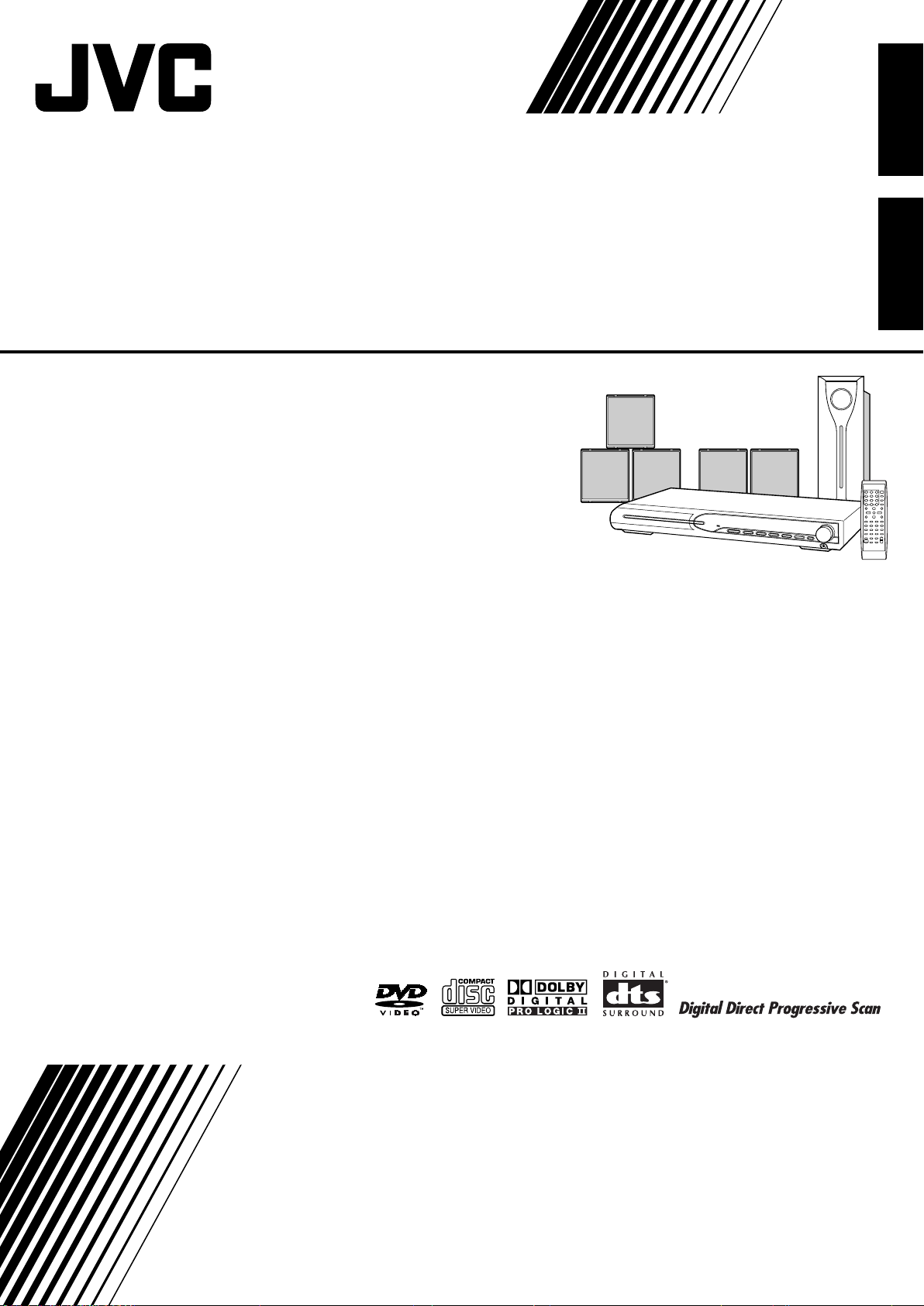
TH-S11
Area suffix
C ------------------------- Canada
(SP-THS11C)
(SP-THS11F)
Lead free solder used in the board (material : Sn-Ag-Cu, melting point : 219 Centigrade)
(SP-THS11S)
(XV-THS11)
(SP-WS11)
TABLE OF CONTENTS
1 PRECAUTION. . . . . . . . . . . . . . . . . . . . . . . . . . . . . . . . . . . . . . . . . . . . . . . . . . . . . . . . . . . . . . . . . . . . . . . . . 1-4
2 SPECIFIC SERVICE INSTRUCTIONS . . . . . . . . . . . . . . . . . . . . . . . . . . . . . . . . . . . . . . . . . . . . . . . . . . . . . . 1-7
3 DISASSEMBLY . . . . . . . . . . . . . . . . . . . . . . . . . . . . . . . . . . . . . . . . . . . . . . . . . . . . . . . . . . . . . . . . . . . . . . . 1-8
4 ADJUSTMENT . . . . . . . . . . . . . . . . . . . . . . . . . . . . . . . . . . . . . . . . . . . . . . . . . . . . . . . . . . . . . . . . . . . . . . . 1-23
5 TROUBLESHOOTING . . . . . . . . . . . . . . . . . . . . . . . . . . . . . . . . . . . . . . . . . . . . . . . . . . . . . . . . . . . . . . . . . 1-25
COPYRIGHT © 2005 Victor Company of Japan, Limited
No.MB413
2005/6
Page 2
SPECIFICATION
Center unit (XV-THS11)
Audio section Front/Center/Surround 33 W per channel, RMS at 6 Ω at 1 kHz,with 10% total harmonic dis-
tortion.
Subwoofer 40 W, RMS at 4 Ω at 100 Hz, with 10% total harmonic distortion.
Video section Video System NTSC
Horizontal Resolution 500 lines
Signal-to-Noise Ratio 64 dB
Video output level Composite 1.0 V(p-p)/75 Ω
S-video-Y 1.0 V(p-p)/75 Ω
S-video-C 0.286 V(p-p)/75 Ω
Component
(Interlace/Progressive)
Tuner section Tuning Range FM 87.5 MHz to 108.0 MHz
AM 530 kHz to 1 710 kHz
Speaker impedance Front/Center/Surround 6 Ω to 16 Ω
Subwoofer 4 Ω to 16 Ω
General Power Requirements AC 120 V , 60 Hz
Power Consumption 135 W (at operation)
Dimensions (W × H × D) 360 mm × 65 mm × 370 mm
Mass 5.3 kg
Y: 1.0 V(p-p)/75 Ω
PB/PR: 0.7 V(p-p)/75 C
1.3 W (in standby mode)
Front speakers (SP-THS11F)
Type 1-Way Bass-Reflex Type(Magnetically-shielded Type)
Speaker 8.0 cm cone × 1
Power Handling Capacity 33 W
Impedance 6 Ω
Frequency Range 90 Hz to 20 000 Hz
Sound Pressure Level 84 dB/W·m
Dimensions (W × H × D) 92 mm × 101 mm × 95 mm
Mass 0.58 kg each
Center speaker (SP-THS11C)
Type 1-Way Bass-Reflex Type(Magnetically-shielded Type)
Speaker 8.0 cm cone × 1
Power Handling Capacity 33 W
Impedance 6 Ω
Frequency Range 90 Hz to 20 000 Hz
Sound Pressure Level 85 dB/W·m
Dimensions (W × H × D) 92 mm × 101 mm × 95 mm
Mass 0.65 kg
1-2 (No.MB413)
Page 3

Surround speakers (SP-THS11S)
Type 1-Way Bass-Reflex Type
Speaker 8.0 cm cone × 1
Power Handling Capacity 33 W
Impedance 6 Ω
Frequency Range 90 Hz to 20 000 Hz
Sound Pressure Level 82 dB/W·m
Dimensions (W × H × D) 92 mm × 101 mm × 95 mm
Mass 0.56 kg each
Subwoofer (SP-WS11)
Type 1-Way Bass-Reflex Type
Speaker 15.0 cm cone × 1
Power Handling Capacity 40 W
Impedance 4 Ω
Frequency Range 40 Hz to 1 800 Hz
Sound Pressure Level 84 dB/W·m
Dimensions (W × H × D) 129 mm × 284 mm × 337 mm
Mass 3.0 kg
Designs & specifications are subject to change without notice.
(No.MB413)1-3
Page 4
SECTION 1
PRECAUTION
1.1 Safety Precautions
(1) This design of this product contains special hardware and
many circuits and components specially for safety purposes. For continued protection, no changes should be made
to the original design unless authorized in writing by the
manufacturer. Replacement parts must be identical to
those used in the original circuits. Services should be performed by qualified personnel only.
(2) Alterations of the design or circuitry of the product should
not be made. Any design alterations of the product should
not be made. Any design alterations or additions will void
the manufacturers warranty and will further relieve the
manufacture of responsibility for personal injury or property
damage resulting therefrom.
(3) Many electrical and mechanical parts in the products have
special safety-related characteristics. These characteristics are often not evident from visual inspection nor can the
protection afforded by them necessarily be obtained by using replacement components rated for higher voltage, wattage, etc. Replacement parts which have these special
safety characteristics are identified in the Parts List of Service Manual. Electrical components having such features
are identified by shading on the schematics and by ( ) on
the Parts List in the Service Manual. The use of a substitute
replacement which does not have the same safety characteristics as the recommended replacement parts shown in
the Parts List of Service Manual may create shock, fire, or
other hazards.
(4) The leads in the products are routed and dressed with ties,
clamps, tubings, barriers and the like to be separated from
live parts, high temperature parts, moving parts and/or
sharp edges for the prevention of electric shock and fire
hazard. When service is required, the original lead routing
and dress should be observed, and it should be confirmed
that they have been returned to normal, after reassembling.
(5) Leakage shock hazard testing
After reassembling the product, always perform an isolation check on the exposed metal parts of the product (antenna terminals, knobs, metal cabinet, screw heads,
headphone jack, control shafts, etc.) to be sure the product
is safe to operate without danger of electrical shock.Do not
use a line isolation transformer during this check.
• Plug the AC line cord directly into the AC outlet. Using a
"Leakage Current Tester", measure the leakage current
from each exposed metal parts of the cabinet, particularly any exposed metal part having a return path to the
chassis, to a known good earth ground. Any leakage current must not exceed 0.5mA AC (r.m.s.).
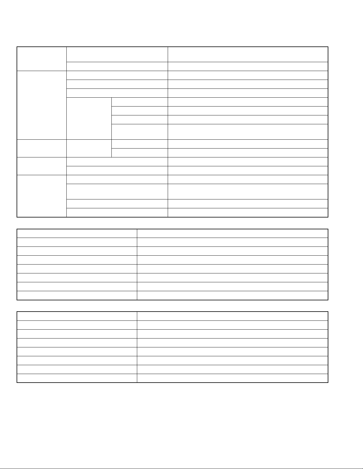
• Alternate check method
Plug the AC line cord directly into the AC outlet. Use an
AC voltmeter having, 1,000Ω per volt or more sensitivity
in the following manner. Connect a 1,500Ω 10W resistor
paralleled by a 0.15µF AC-type capacitor between an ex-
posed metal part and a known good earth ground.
Measure the AC voltage across the resistor with the AC
voltmeter.
Move the resistor connection to each exposed metal
part, particularly any exposed metal part having a return
path to the chassis, and measure the AC voltage across
the resistor. Now, reverse the plug in the AC outlet and
repeat each measurement. Voltage measured any must
not exceed 0.75 V AC (r.m.s.). This corresponds to 0.5
mA AC (r.m.s.).
AC VOLTMETER
(Having 1000
ohms/volts,
or more sensitivity)
0.15 F AC TYPE
Place this
probe on
1500 10W
Good earth ground
1.2 Warning
(1) This equipment has been designed and manufactured to
meet international safety standards.
(2) It is the legal responsibility of the repairer to ensure that
these safety standards are maintained.
(3) Repairs must be made in accordance with the relevant
safety standards.
(4) It is essential that safety critical components are replaced
by approved parts.
(5) If mains voltage selector is provided, check setting for local
voltage.
1.3 Caution
Burrs formed during molding may be left over on some parts
of the chassis.
Therefore, pay attention to such burrs in the case of preforming repair of this system.
1.4 Critical parts for safety
In regard with component parts appearing on the silk-screen
printed side (parts side) of the PWB diagrams, the parts that are
printed over with black such as the resistor ( ), diode ( )
and ICP ( ) or identified by the " " mark nearby are critical
for safety. When replacing them, be sure to use the parts of the
same type and rating as specified by the manufacturer.
(This regulation dose not Except the J and C version)
each exposed
metal part.
1-4 (No.MB413)
Page 5
1.5 Preventing static electricity
Electrostatic discharge (ESD), which occurs when static electricity stored in the body, fabric, etc. is discharged, can destroy the laser
diode in the traverse unit (optical pickup). Take care to prevent this when performing repairs.
1.5.1 Grounding to prevent damage by static electricity
Static electricity in the work area can destroy the optical pickup (laser diode) in devices such as laser products.
Be careful to use proper grounding in the area where repairs are being performed.
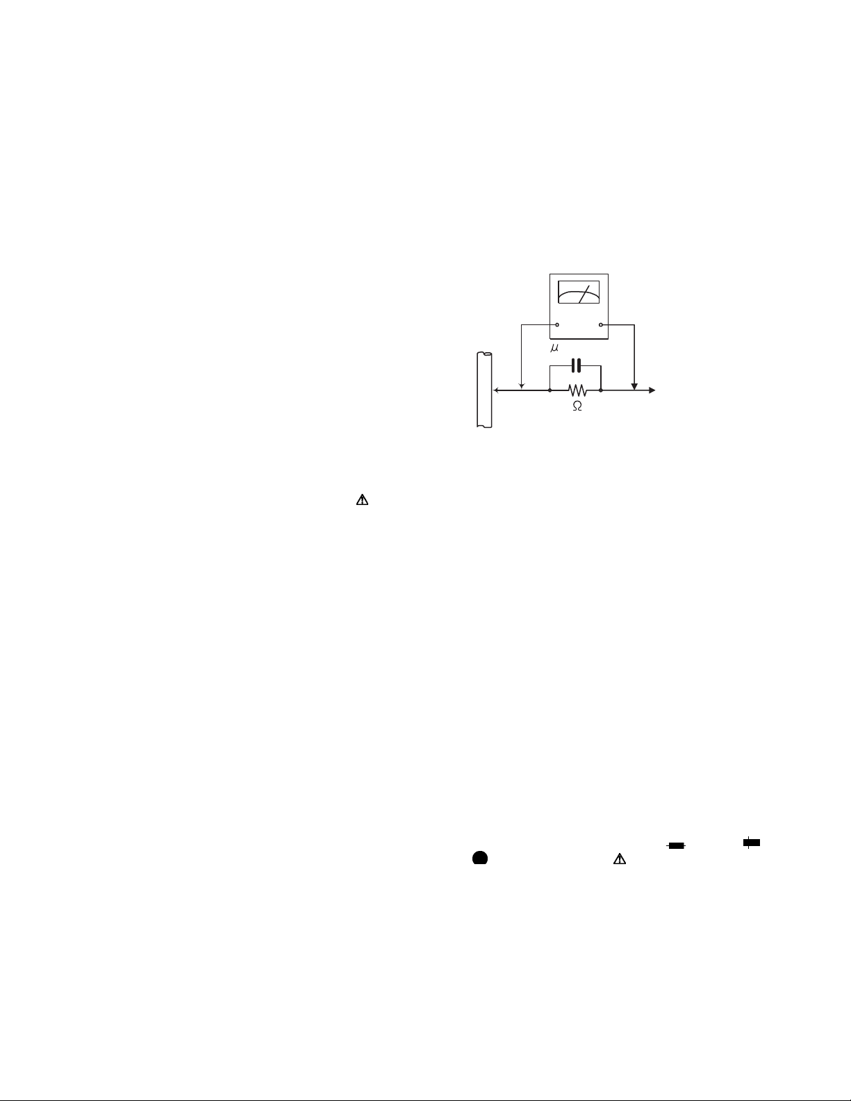
(1) Ground the workbench
Ground the workbench by laying conductive material (such as a conductive sheet) or an iron plate over it before placing the
traverse unit (optical pickup) on it.
(2) Ground yourself
Use an anti-static wrist strap to release any static electricity built up in your body.
(caption)
Anti-static wrist strap
1M
Conductive material
(conductive sheet) or iron palate
(3) Handling the optical pickup
• In order to maintain quality during transport and before installation, both sides of the laser diode on the replacement optical
pickup are shorted. After replacement, return the shorted parts to their original condition.
(Refer to the text.)
• Do not use a tester to check the condition of the laser diode in the optical pickup. The tester's internal power source can easily
destroy the laser diode.
1.6 Handling the traverse unit (optical pickup)
(1) Do not subject the traverse unit (optical pickup) to strong shocks, as it is a sensitive, complex unit.
(2) Cut off the shorted part of the flexible cable using nippers, etc. after replacing the optical pickup. For specific details, refer to the
replacement procedure in the text. Remove the anti-static pin when replacing the traverse unit. Be careful not to take too long a
time when attaching it to the connector.
(3) Handle the flexible cable carefully as it may break when subjected to strong force.
(4) I t is not possible to adjust the semi-fixed resistor that adjusts the laser power. Do not turn it.
1.7 Attention when traverse unit is decomposed
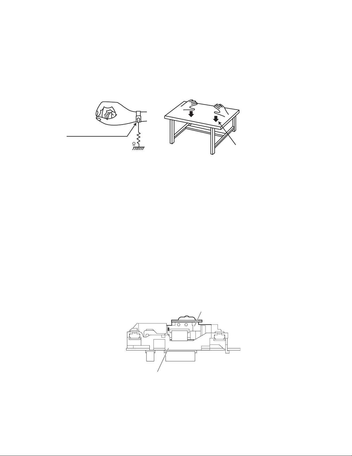
*Please refer to "Disassembly method" in the text for the pickup unit.
• Apply solder to the short land sections before the flexible wire is disconnected from the connecto on the servo board. (If the flexible
wire is disconnected without applying solder, the pickup may be destroyed by static electricity.)
• In the assembly, be sure to remove solder from the short land sections after connecting the flexible wire.
DVD pickup
Traverse mechanism assembly
(No.MB413)1-5
Page 6
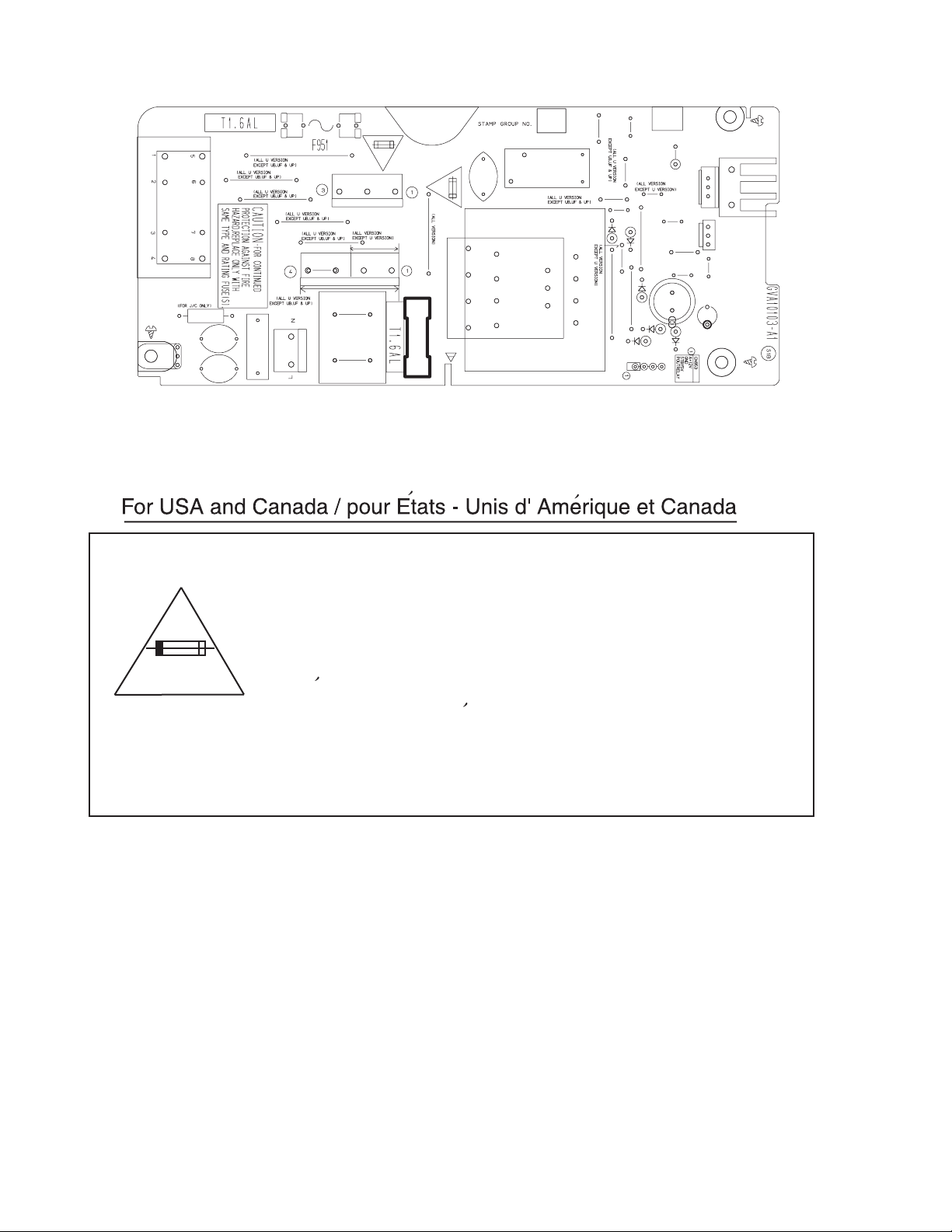
1.8 Importance administering point on the safety
EP950
Z953
B955
S950
R990
C960
B954
B953
C959
C961
CN950
Z952
C950
CN951
B952
B951
B974
CN952
B957
B956
T950
B950
3A-125V
F950
RY950
B968
B967
R952
B963
B973
B961
B970
D955
B964
D957
B959
B972
B971
B965
B969
D951
B960
D958
D956
FW953
HS950
Q950
Q951
B966
C951
C958
D959
Caution: For continued protection against risk of
fire, replace only with same type 3A/125V for F950.
This symbol specifies type of fast operating fuse.
Precaution: Pour eviter risques de feux, remplacez
le fusible de surete de F950 comme le meme type
que 3A/125V.
Ce sont des fusibles suretes qui functionnes rapide.
^
1-6 (No.MB413)
Page 7

SECTION 2
SPECIFIC SERVICE INSTRUCTIONS
This service manual does not describe SPECIFIC SERVICE INSTRUCTIONS.
(No.MB413)1-7
Page 8
SECTION 3
DISASSEMBLY
3.1 Main body section
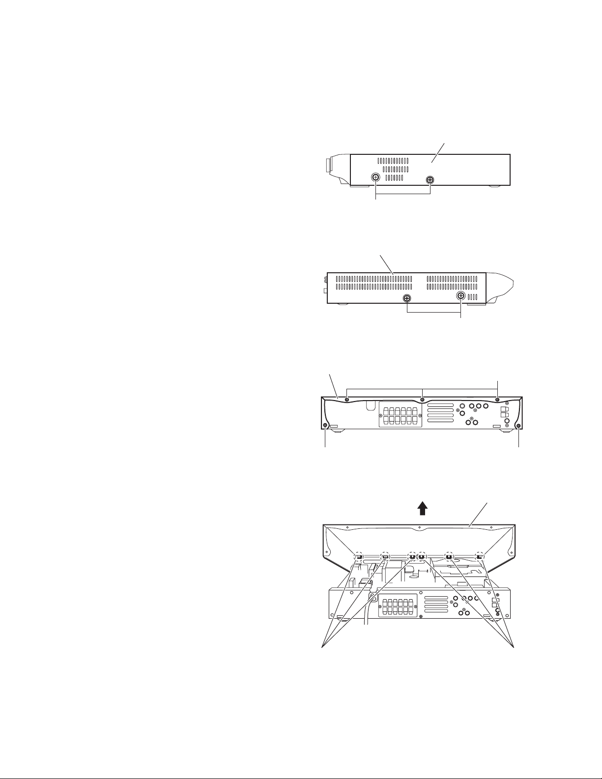
3.1.1 Removing the metal cover
(See Figs.1 to 4)
(1) From the both sides of the main body, remove the four
screws A attaching the metal cover. (See Figs.1 and 2.)
(2) From the back side of the main body, remove the five
screws B attaching the metal cover. (See Fig.3.)
(3) Lift the rear section of the metal cover in the direction of the
arrow while extending the lower sections of the metal cover, release the claws a using a longer screwdriver from the
inside as required. (See Fig.4.)
Note:
Do not damage any parts and boards inside the main body
when releasing the claws a using the longer screwdriver. (See
Fig.4.)
Metal cover
A
Fig.1
Metal cover
A
Fig.2
Metal cover
B
B B
Fig.3
Metal cover
1-8 (No.MB413)
a
Fig.4
a
Page 9
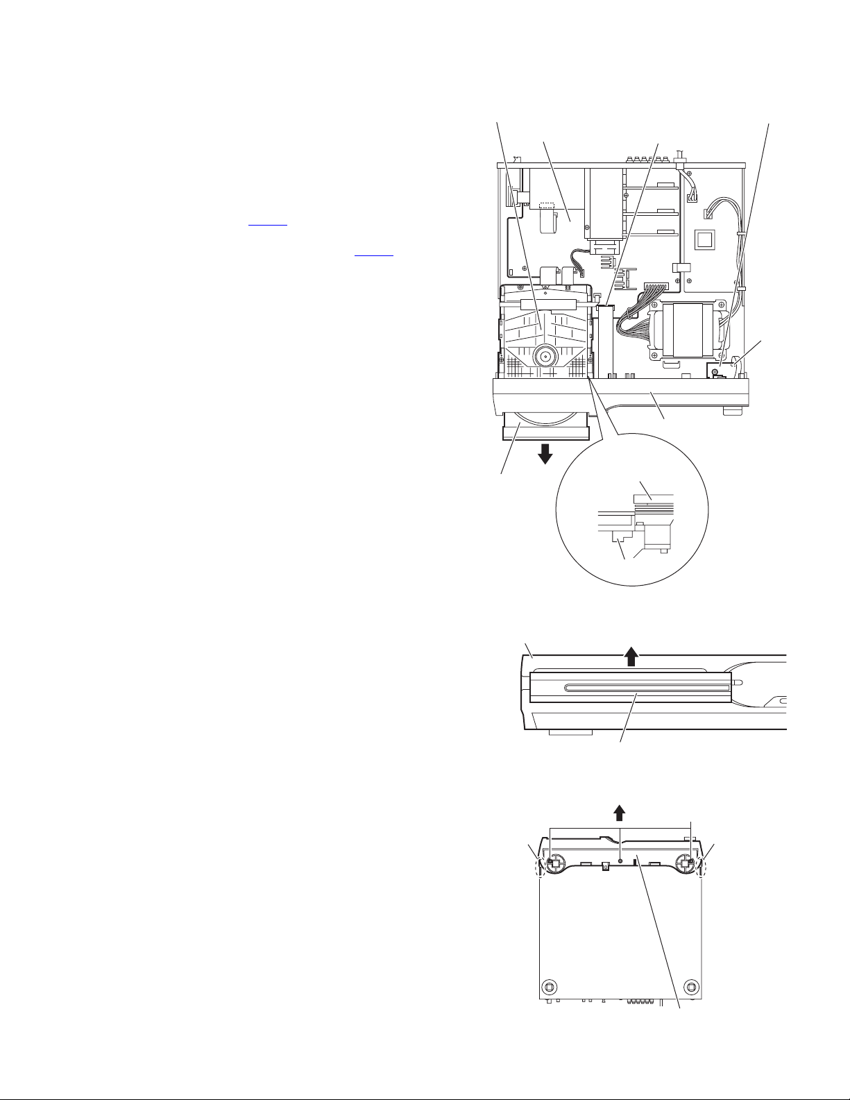
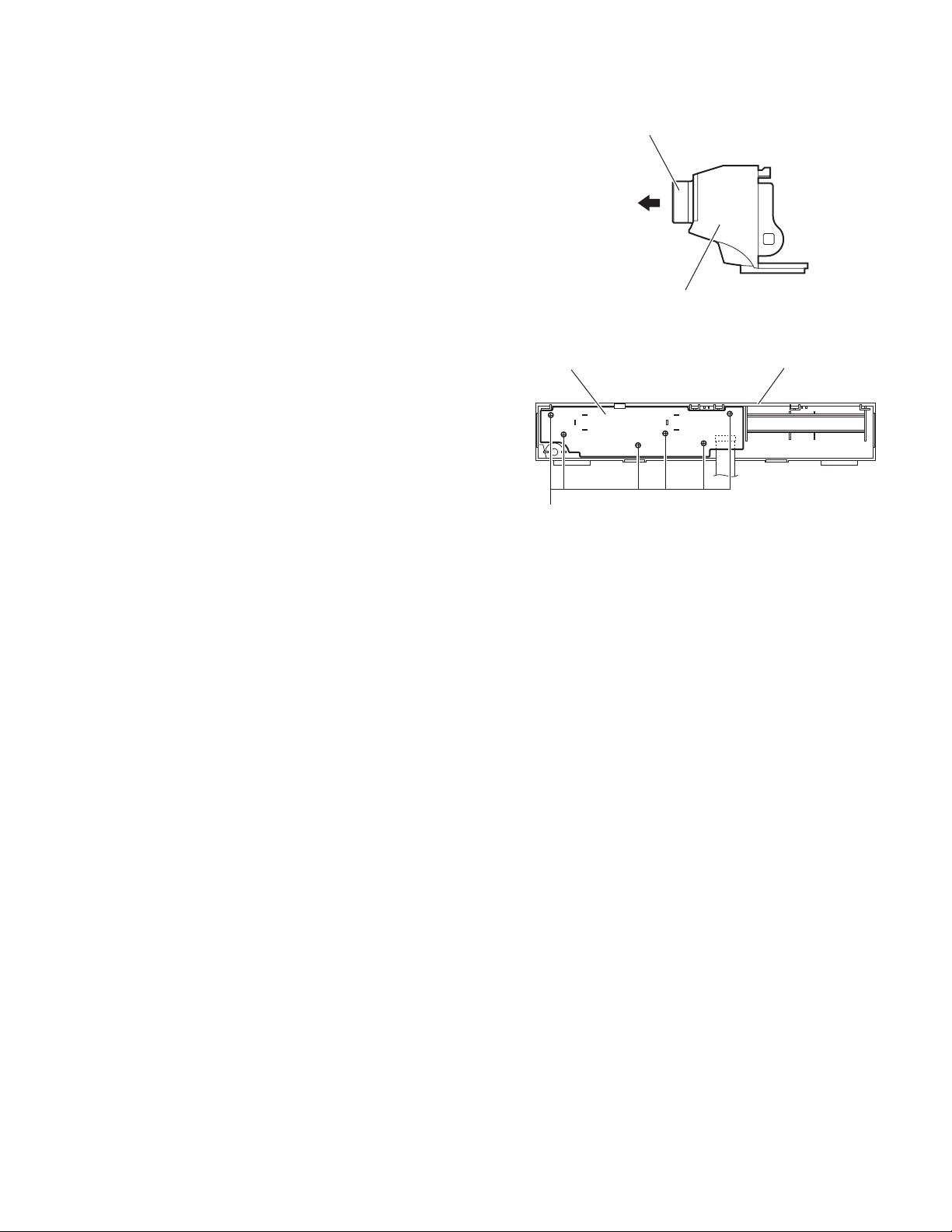
3.1.2 Removing the front panel assembly
(See Figs.5 to 7)
• Remove the metal cover.
(1) From the right side of the DVD mechanism assembly, push
the slide cam and pull the tray assembly out of the main
body in the direction of the arrow. (See Fig.5.)
(2) From the front side of the main body, remove the CD fitting
assembly from the tray assembly in the direction of the arrow and push in the tray assembly as before. (See Fig.6.)
(3) From the top side of the main body, disconnect the card
wire from the connector CN400
Fig.5.)
(4) Disconnect the card wire from the connector CN510
HP terminal board. (See Fig.5.)
(5) From the bottom side of the main body, remove the three
screws C attaching the front panel assembly. (See Fig.7.)
(6) From both sides and back side of the main body, remove
the front panel assembly in the direction of the arrow while
releasing the joints b. (See Fig.7.)
on the main board. (See
on the
DVD mechanism assembly
Main board
HP terminal board
CN400
CN510
Front panel assembly
Tray assembly
Front panel assembly
CD fitting assembly
b
DVD mechanism
assembly
Slide cam
Fig.5
Fig.6
C
b
Front panel assembly
Fig.7
(No.MB413)1-9
Page 10
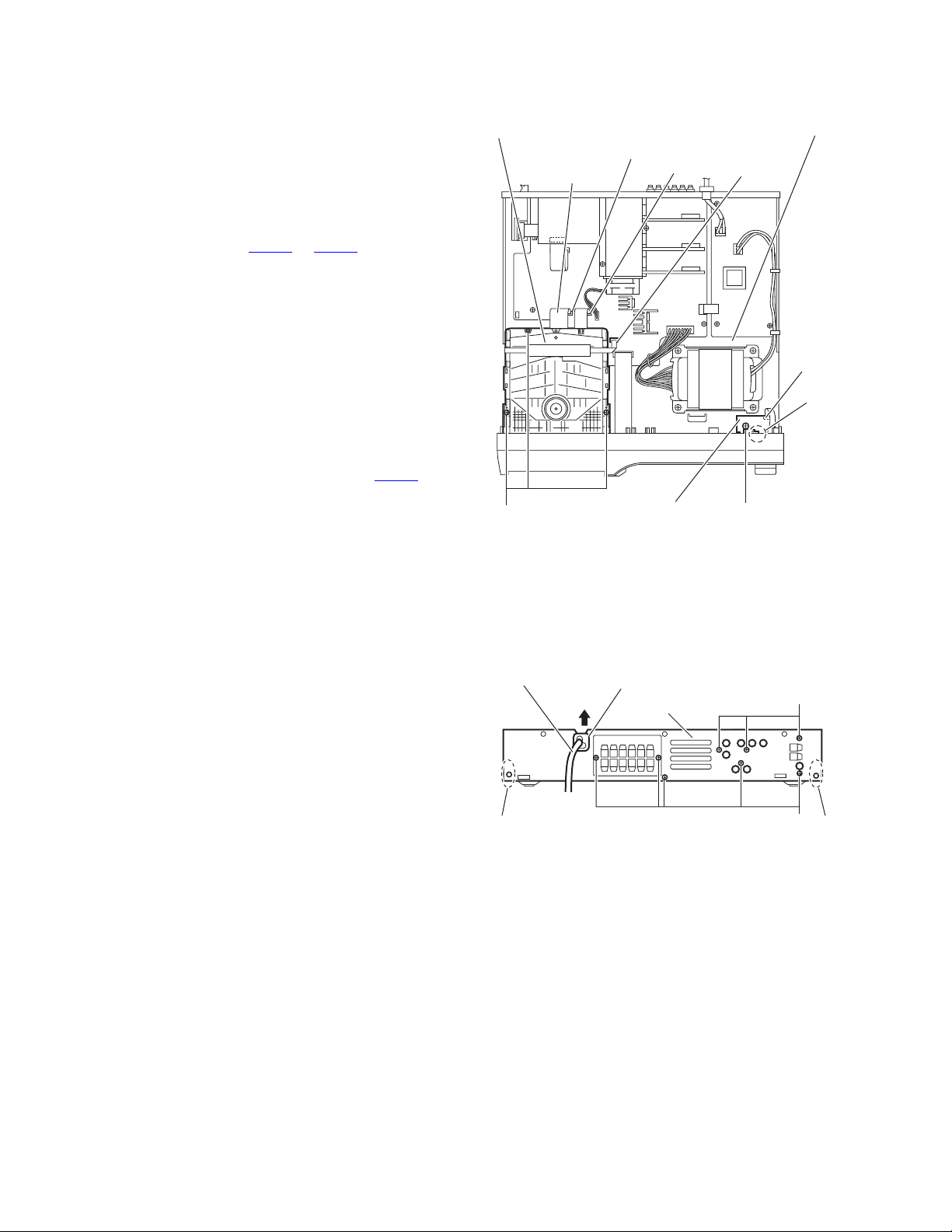
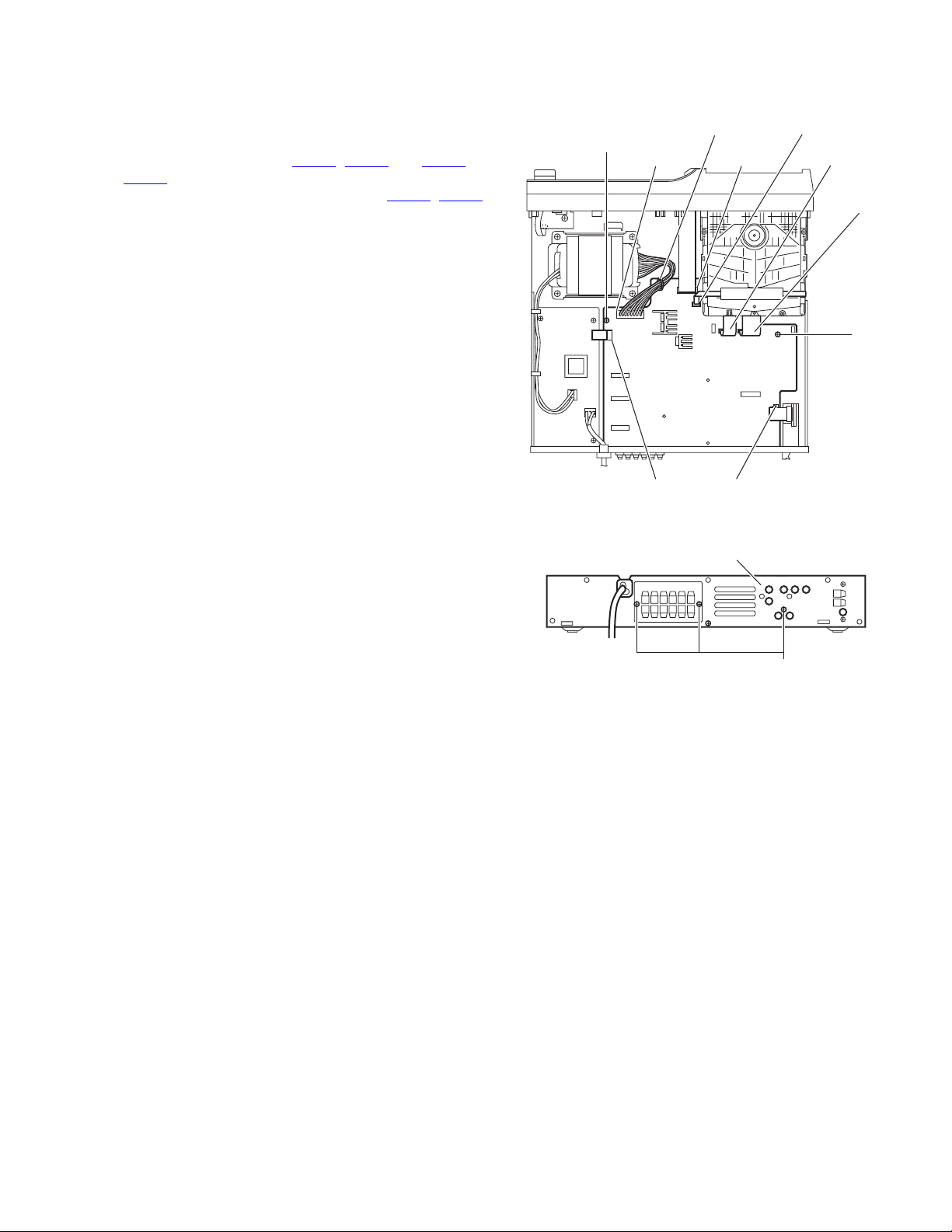
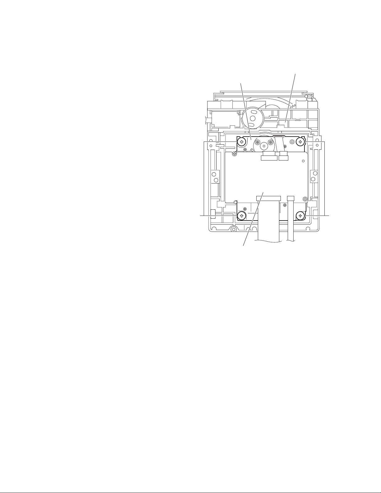
3.1.3 Removing the DVD mechanism assembly
(See Figs.5,6 and 8)
• Remove the metal cover.
(1) From the right side of the DVD mechanism assembly, push
the slide cam and pull the tray assembly out of the main
body in the direction of the arrow. (See Fig.5.)
(2) From the front side of the main body, remove the CD fitting
from the tray assembly in the direction of the arrow and
push in the tray assembly as before. (See Fig.6.)
(3) From the top side of the main body, disconnect the card
wires from the connectors CN403
board. (See Fig.8.)
(4) Remove the three screws D attaching the DVD mechanism
assembly to the chassis base. (See Fig.8.)
3.1.4 Removing the HP terminal board
(See Fig.8)
• Remove the metal cover.
Reference:
Remove the front panel assembly as required. (See 3.1.2 "Removing the front panel assembly".)
(1) From the top side of the main body, remove the screw E at-
taching the HP terminal board to the chassis base.
(2) Disconnect the card wires from the connectors CN510
the HP terminal board. (See Fig.8.)
(3) Take out the HP terminal board from the main body.
Reference:
When attaching the HP terminal board, align the hole on the
HP terminal board to the projection c of the chassis base before attaching the screw E.
to CN405 on the main
on
DVD mechanism assembly
CN404
Card wires
D
HP terminal board
CN403
Fig.8
Chassis base
CN405
CN510
c
E
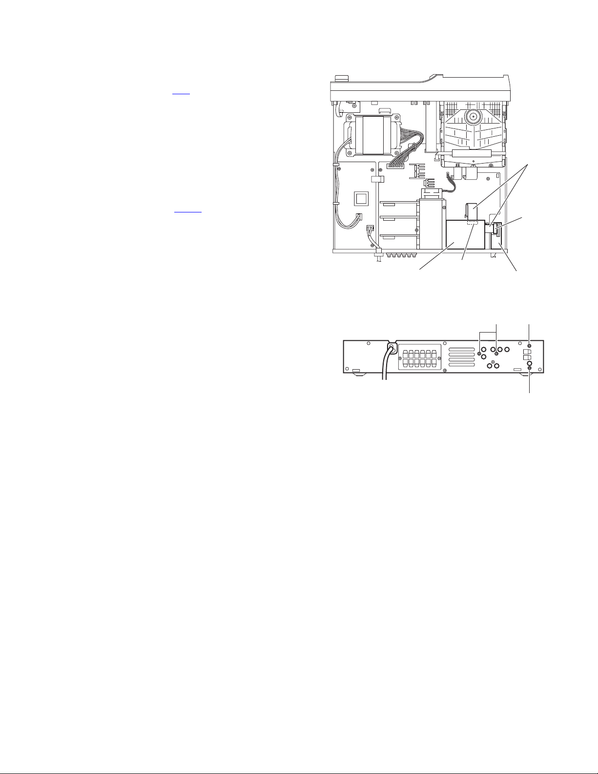
3.1.5 Removing the rear panel
(See Fig.9)
• Remove the metal cover.
(1) From the back side of the main body, remove the strain re-
lief attaching the power cord in the direction of the arrow.
(2) Remove the eight screws F attaching the rear panel to the
main body.
(3) Release the joints d, and remove the rear panel from the
main body.
Power cord
d d
Strain relief
Rear panel
Fig.9
F
F
1-10 (No.MB413)
Page 11
3.1.6 Removing the tuner assembly
(See Figs.10 and 11)
• Remove the metal cover.
(1) From the top side of the main body, disconnect the card
wire from the connector CN1
Fig.10.)
(2) From the back side of the main body, remove the two
screws G attaching the tuner assembly to the rear panel.
(See Fig.11.)
(3) Take out the tuner assembly from the main body.
3.1.7 Removing the video board
(See Figs.10 and 11)
• Remove the metal cover.
(1) From the top side of the main body, disconnect the card
wire from the connector CN350
Fig.10.)
(2) From the back side of the main body, remove the two
screws H attaching the video board to the rear panel. (See
Fig.11.)
(3) Take out the video board from the main body.
on the tuner assembly. (See
on the video board. (See
Card wires
CN1
CN350
Videol board Tuner assembly
Fig.10
Fig.11
H
G
G
(No.MB413)1-11
Page 12
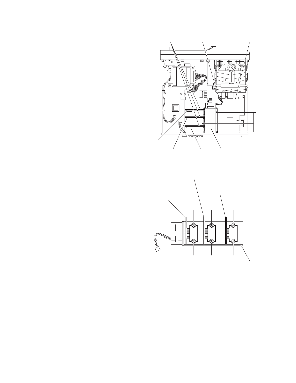
3.1.8 Removing the power amp.boards
(See Figs.12 and 13)
• Remove the metal cover and video board.
(1) From the top side of the main board, remove the three
screws J attaching the heat sink. (See Fig.12.)
(2) Disconnect the wire from the connector CN100
board. (See Fig.8.)
(3) Disconnect the each power amp.boards connecters from
the connectors CN271
(See Fig.12.)
Reference:
When attaching the heat sink with power amp.boards,
confirm the connectors CN281
ready lock before attaching the screws J.
(4) Take out the heat sink with power amp.boards from the
main board. (See Fig.12.)
(5) Remove the two screws K, two screws M and two screws
N attaching the heat sink. (See Fig.13.)
(6) Remove the each power amp.boards from the heat sink.
, CN276, CN281 on the main board.
, CN276 and CN271 al-
on the main
Power amp. board
CN100
Main board
J
CN281
CN276
Power amp. board
Power amp. board
(CEN & SW)
CN271
Fig.12
(SL & SR)
K
K
Fig.13
Heat sink
Heat sink
Power amp. board
(FL & FR)
M
M
N
N
Heat sink
1-12 (No.MB413)
Page 13
3.1.9 Removing the main board
(See Figs.14 and 15)
• Remove the metal cover, video board and heat sink with power
amp. boards.
(1) From the top side of the main body, disconnect the card
wires from the connectors CN400
, on the main board. (See Fig.14.)
CN405
(2) Disconnect the wires from the connectors CN102, CN101
on the main board. (See Fig.14.)
Reference:
After connecting the wires, fix the wires with the wire
clamp.
(3) Remove the two screws P attaching the main board to the
chassis base. (See Fig.14.)
(4) From the back side of the main body, remove the three
screws Q attaching the main board to the rear panel. (See
Fig.15.)
(5) Take out the main board from the main body.
, CN401 and CN403 to
Wire clamp
P
CN102 CN400
CN110 CN401
CN405
CN403
CN404
P
Fig.14
Rear panel
Fig.15
Q
(No.MB413)1-13
Page 14
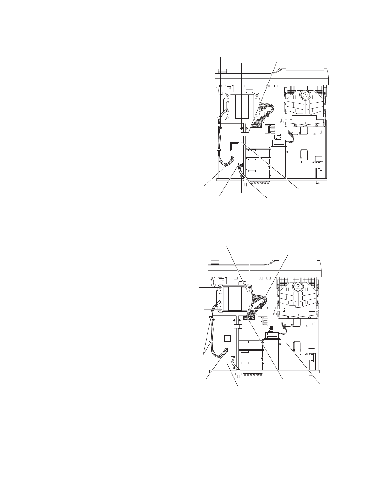
3.1.10 Removing the transformer board
(See Fig.16)
• Remove the metal cover.
(1) From the top side of the main body, disconnect the wires
from the connectors CN950, CN952 on the transformer
board.
(2) Disconnect the wires from the connectors CN101
main board.
(3) Remove the three screws R attaching the transformer
board.
(4) Take out the transformer board from the main body.
on the
R
CN101
3.1.11 Removing the power transformer
(See Fig.17)
• Remove the metal cover.
(1) From the top side of the main body, remove the tie bands
and wire clamp bundling the wires.
(2) Disconnect the wire from the connector CN952
transformer board.
(3) Disconnect the wire from the connector CN102 on the main
board.
Reference:
After connecting the wires to the connectors, bundle the
wires with the wire clamps and new tie bands as before.
(4) Remove the four screws S and take out the power trans-
former from the main body.
on the
CN952
CN950
Power transformer
S
Tie
bands
R
Fig.16
S
Transformer board
Power cord
Wire clamp
S
1-14 (No.MB413)
CN952
Transformer board
Fig.17
CN102
Main board
Page 15
3.1.12 Removing the front board
(See Figs.18 and 19)
• Remove the metal cover and front panel assembly.
(1) From the front side of the front panel assembly, pull out the
volume knob in the direction of the arrow. (See Fig.18.)
(2) From the inside of the front panel assembly, remove the six
screws T attaching the front board. (See Fig.19.)
(3) Take out the front board from the front panel assembly.
Volume knob
Front panel assembly
Fig.18
Front board
T
Front panel assembly
Fig.19
(No.MB413)1-15
Page 16
3.2 DVD mechanism section
• Remove the DVD mechanism assembly from the main body.
3.2.1 Removing the traverse mechanism assembly
(See Fig.1)
From the bottom side of the DVD mechanism assembly, remove
the four screws A attaching the traverse mechanism assembly
and take out the traverse mechanism assembly with the DVD
module board.
DVD mechanism assembly
Traverse mechanism assembly
AA
DVD module board
Fig.1
1-16 (No.MB413)
Page 17
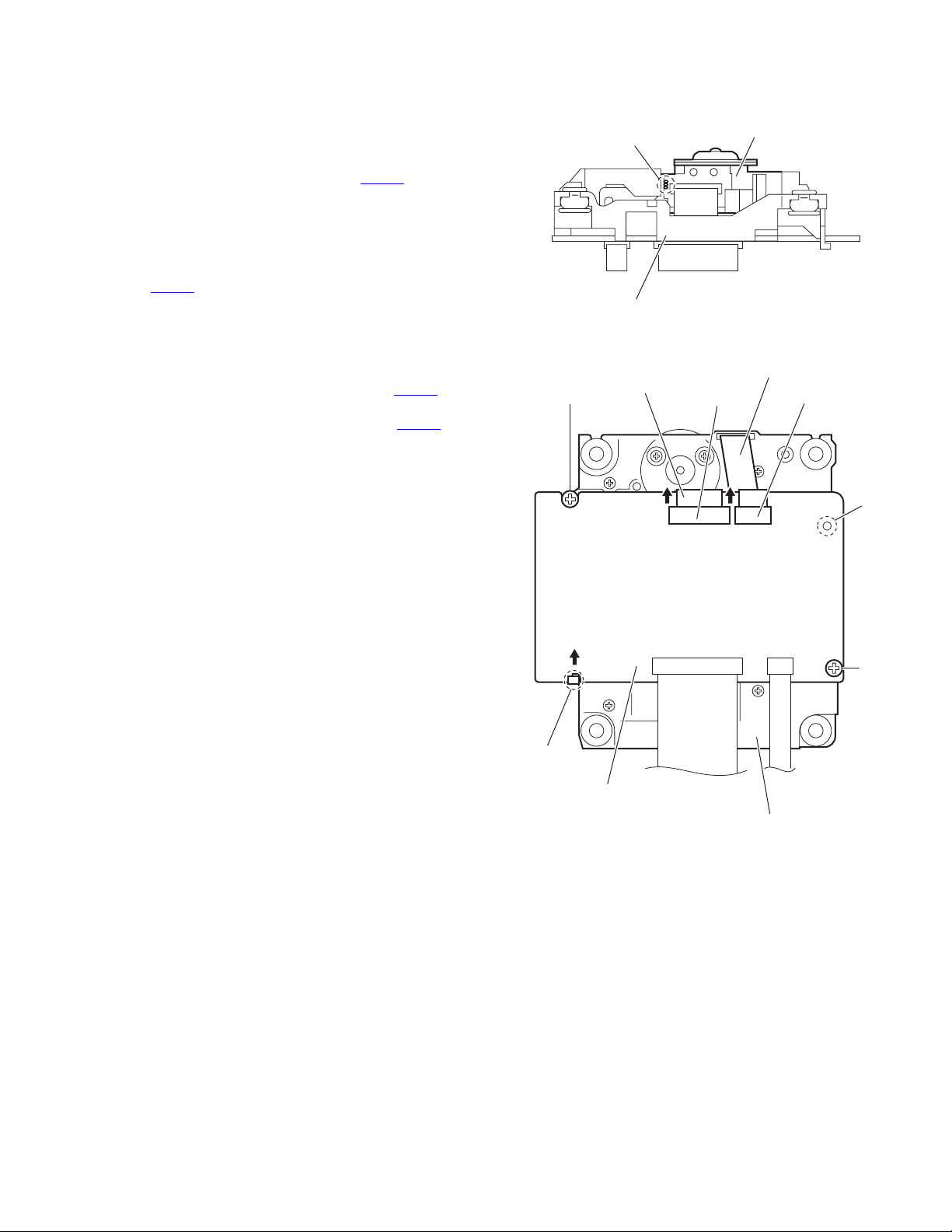
3.2.2 Removing the DVD module board
(See Figs.2 and 3)
• Remove the traverse mechanism assembly.
(1) From the side of the traverse mechanism assembly, solder
the short land sections a on the DVD pickup. (See Fig.2.)
(2) From the bottom side of the traverse mechanism assem-
bly, release the lock of the connector CN101
module board in the direction of the arrow and disconnect
the card wire. (See Fig.3.)
Caution:
• Solder the short land sections a on the DVD pickup before disconnecting the card wire from the connector
on the DVD module board. If the card wire is
CN101
disconnected without attaching solder, the DVD pickup may be destroyed by static electricity. (See Figs.2
and 3.)
• When attaching the DVD module board, be sure to remove solders from the short land sections a after connecting the card wire to the connector CN101
DVD module board. (See Figs.2 and 3.)
(3) Disconnect the card wire from the connector CN201
DVD module board. (See Fig.3.)
(4) Remove the two screws B attaching the DVD module
board. (See Fig.3.)
(5) Remove the DVD module board from the engagement sec-
tion b in an upward and remove the engagement section c
in the direction of the arrow. (See Fig.3.)
on the DVD
on the
on the
a
Traverse mechanism assembly
Card wire
B
DVD pickup
Fig.2
Card wire
CN101 CN201
b
c
DVD module board
B
Traverse mechanism assembly
Fig.3
(No.MB413)1-17
Page 18
3.2.3 Removing the DVD pickup
(See Figs.2,4 to 6)
• Remove the traverse mechanism assembly.
(1) From the side of the traverse mechanism assembly, solder
the short land sections a on the DVD pickup. (See Fig.2.)
(2) Release the lock of the connector on the DVD pickup in the
direction of the arrow and disconnect the card wire. (See
Fig.4.)
Caution:
• Solder the short land sections a on the DVD pickup before disconnecting the card wire from the connector on
the DVD pickup. If the card wire is disconnected without attaching solder, the DVD pickup may be destroyed by static electricity. (See Figs.2 and 4.)
• When attaching the DVD pickup, be sure to remove
solders from the short land sections a after connecting
the card wire to the connector on the DVD pickup.
(See Figs.2 and 4.)
(3) Remove the screw C and remove the feed bracket from the
sections d. (See Fig.4.)
(4) Release the claw e of the thrust spring in the direction of
the arrow and remove the thrust spring. (See Fig.4.)
(5) Remove the guide shaft of the DVD pickup from the section
f on the traverse mechanism assembly and remove the
guide shaft from the section g while moving it in the direction of the arrow. (See Fig.5.)
(6) Remove the DVD pickup from the section h of the traverse
mechanism assembly and take out the DVD pickup with
the guide shaft. (See fig.5.)
(7) From the bottom side of the DVD pickup, remove the two
screws D attaching the rack arm and rack arm spring. (See
Fig.6.)
(8) Pull the guide shaft out of the DVD pickup. (See Fig.6.)
Feed bracket
C
Card wire
Traverse mechanism assembly
f
Guide shaft
e
Thrust spring
Connector
Fig.4
Thrust spring
DVD pickup
Torsion spring
g
1-18 (No.MB413)
DVD pickup
Guide shaft
h
Fig.5
DVD pickup
Rack arm
Rack arm spring
D
Fig.6
Page 19
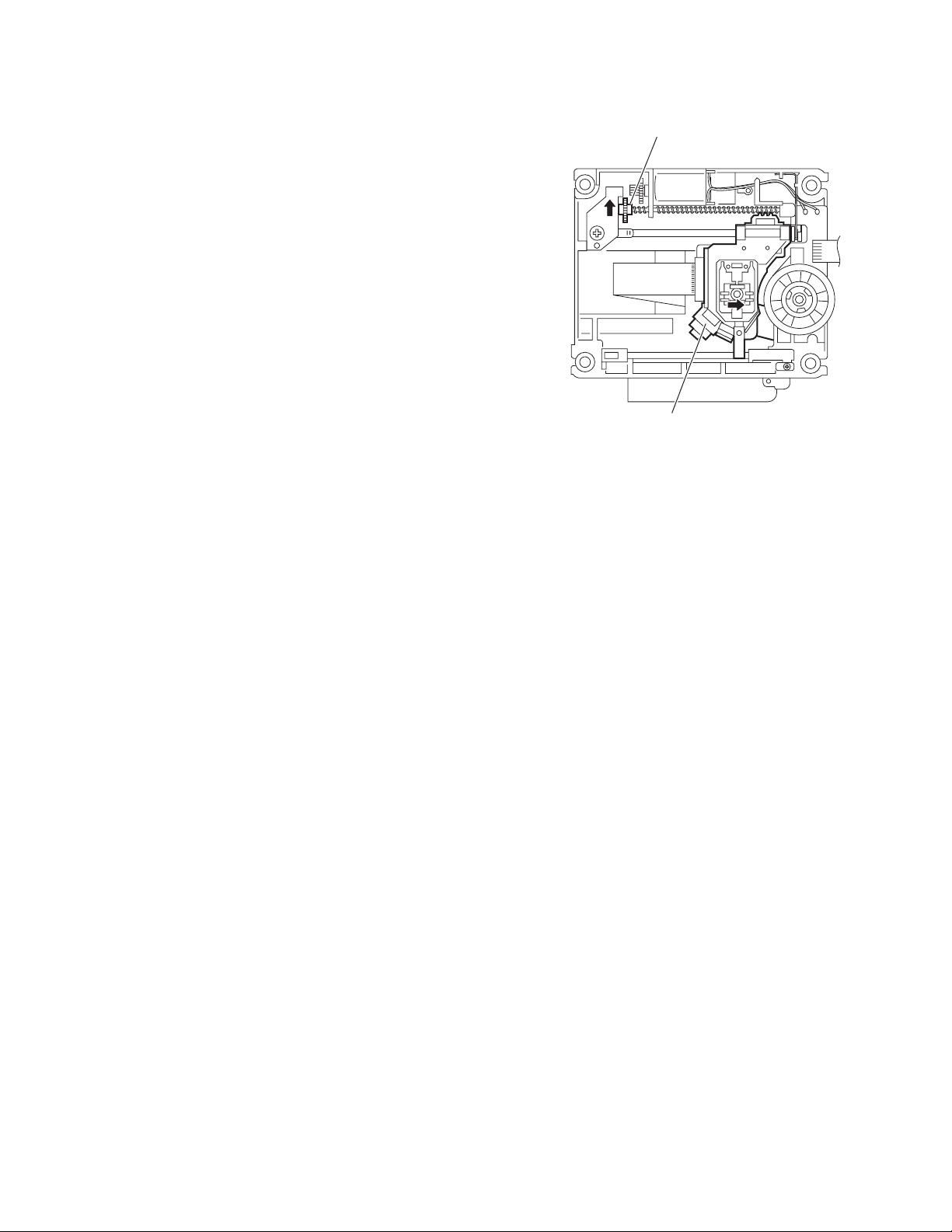
3.2.4 Attaching the DVD pickup
(See Figs.2,4 to 7)
• See "3.2.3 Removing the DVD pickup".
(1) Attach the guide shaft, rack arm and rack arm spring to the
DVD pickup. (See Fig.6.)
(2) Align the DVD pickup to the section h of the traverse mech-
anism assembly first, and set the both ends of the guide
shaft of the DVD pickup in the sections f and g of the
traverse mechanism assembly. (See Fig.5.)
Reference:
When attaching the guide shaft to the section g, attach it
under the rod spring. (See Fig.5.)
(3) Attach the feed bracket and thrust spring. (See Fig.4.)
(4) Remove solders from the short land sections a after con-
necting the card wire to the connector on the DVD pickup.
(See Figs.2 and 4.)
(5) Turn the screw shaft gear in the direction of the arrow 1 to
move the DVD pickup fully in the direction of the arrow 2.
(See Fig.7.)
Screw shaft gear
1
22
DVD pickup
Fig.7
(No.MB413)1-19
Page 20
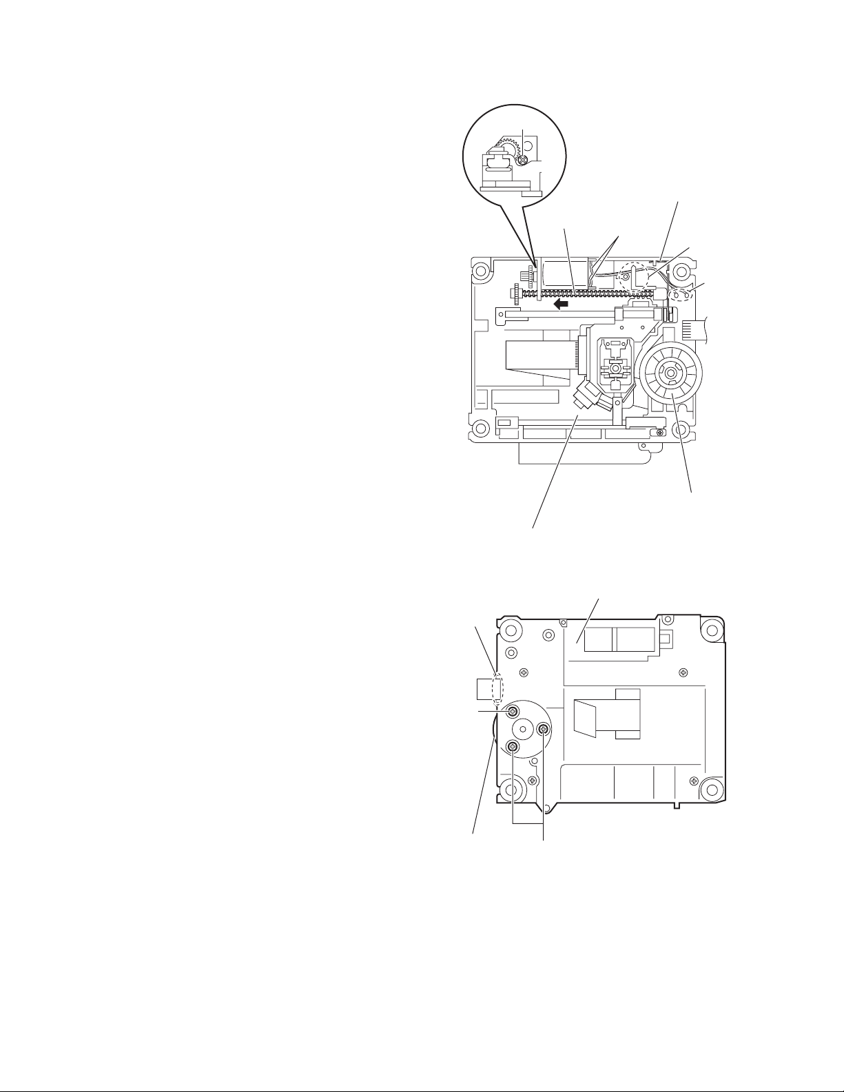
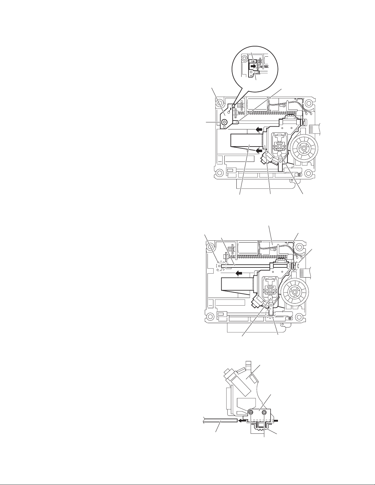
3.2.5 Removing the feed motor
(See Figs.4,8 and 9)
• Remove the traverse mechanism assembly.
(1) From the top side of the traverse mechanism assembly, re-
move the screw C and remove the feed bracket from the
sections d. (See Fig.4.)
(2) Release the claw e of the thrust spring in the direction of
the arrow and remove the thrust spring. (See Fig.4.)
(3) Remove the wires from the soldered section j on the spin-
dle motor board. (See Fig.8.)
Reference:
• When attaching the feed motor, pass the wire through
the section k on the traverse mechanism assembly.
(See Fig.8.)
• Pass the wire through the lower section of the rod
spring. (See Fig.8.)
(4) Remove the screw shaft in the direction of the arrow. (See
Fig.8.)
(5) From the side of the traverse mechanism assembly, re-
move the screw E attaching the feed motor. (See Fig.8.)
(6) Take out the feed motor from the traverse mechanism as-
sembly.
3.2.6 Removing the spindle motor board
(See Figs.8 and 9)
• Remove the traverse mechanism assembly and DVD module
board.
(1) From the top side of the traverse mechanism assembly, re-
move the wires from the soldered section j on the spindle
motor board. (See Fig.8.)
(2) From the bottom side of the traverse mechanism assem-
bly, remove the three screws F attaching the spindle motor
board. (See Fig.9.)
Reference:
• When attaching the spindle motor board, pass the wire
through the section m on the traverse mechanism assembly.
(See Fig.9.)
• After attaching the screws F, apply bond as before.
E
Screw shaft
Traverse mechanism assembly
Traverse mechanism assembly
m
Wires
Spindle motor board
Fig.8
Rod spring
k
j
1-20 (No.MB413)
F
Spindle motor
board
F
Fig.9
Page 21
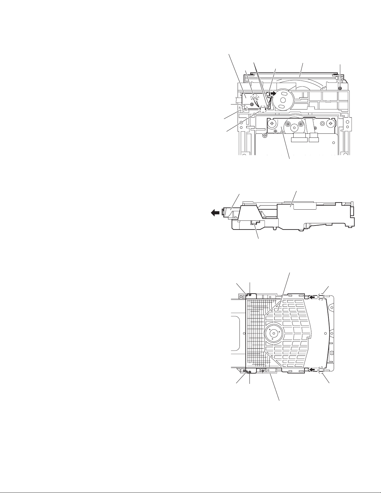
3.2.7 Removing the DVD loading switch board
(See Fig.10.)
(1) From the bottom side of the DVD mechanism assembly, re-
move the wires from the soldered sections n on the DVD
loading switch board.
(2) Remove the screw G attaching the DVD loading switch
board.
(3) Lift the DVD loading switch board while pressing the claw
p of the DVD mechanism assembly in the direction of the
arrow and remove it from the section q.
Reference:
Pass the wires through the section r after attaching the DVD
loading switch board to the DVD mechanism assembly.
3.2.8 Removing the loading motor
(See Figs.10 to 14)
(1) From the bottom side of the DVD mechanism assembly, re-
move the wires from the soldered section n on the DVD
loading switch board. (See Fig.10.)
(2) Remove the screw H attaching the tray assembly. (See
Fig.10.)
(3) From the right side of the DVD mechanism assembly, push
the slide cam and pull the tray assembly out of the DVD
mechanism assembly in the direction of the arrow. (See
Fig.11.)
(4) From the top side of the DVD mechanism assembly, re-
move the two screws J attaching the clamper base. (See
Fig.12.)
(5) Lift the clamper base in an upward direction to remove it
from the engagement sections s and remove the engagement sections t in the direction of the arrow. (See Fig.12.)
(6) Remove the two screws K attaching the tray assembly and
take out the tray assembly from the DVD mechanism assembly. (See Fig.13.)
(7) Remove the belt from the motor pulley. (See Fig.14.)
Note:
Take care not to attach grease on the belt.
(8) Remove the two screws M attaching the loading motor to
the DVD mechanism assembly and take out the loading
motor from the bottom side of the DVD mechanism assembly. (See Fig.14.)
Reference:
Pass the wires through the section r after attaching the loading
motor to the DVD mechanism assembly. (See Fig.10.)
DVD loading switch board
Wires
n
G
q
r
DVD mechanism assembly
Tray assembly
Slide cam
J
s
DVD mechanism assembly
Clamper base
Tray assembly
p
Fig.10
Fig.11
H
t
s
t
J
DVD mechanism assembly
Fig.12
(No.MB413)1-21
Page 22
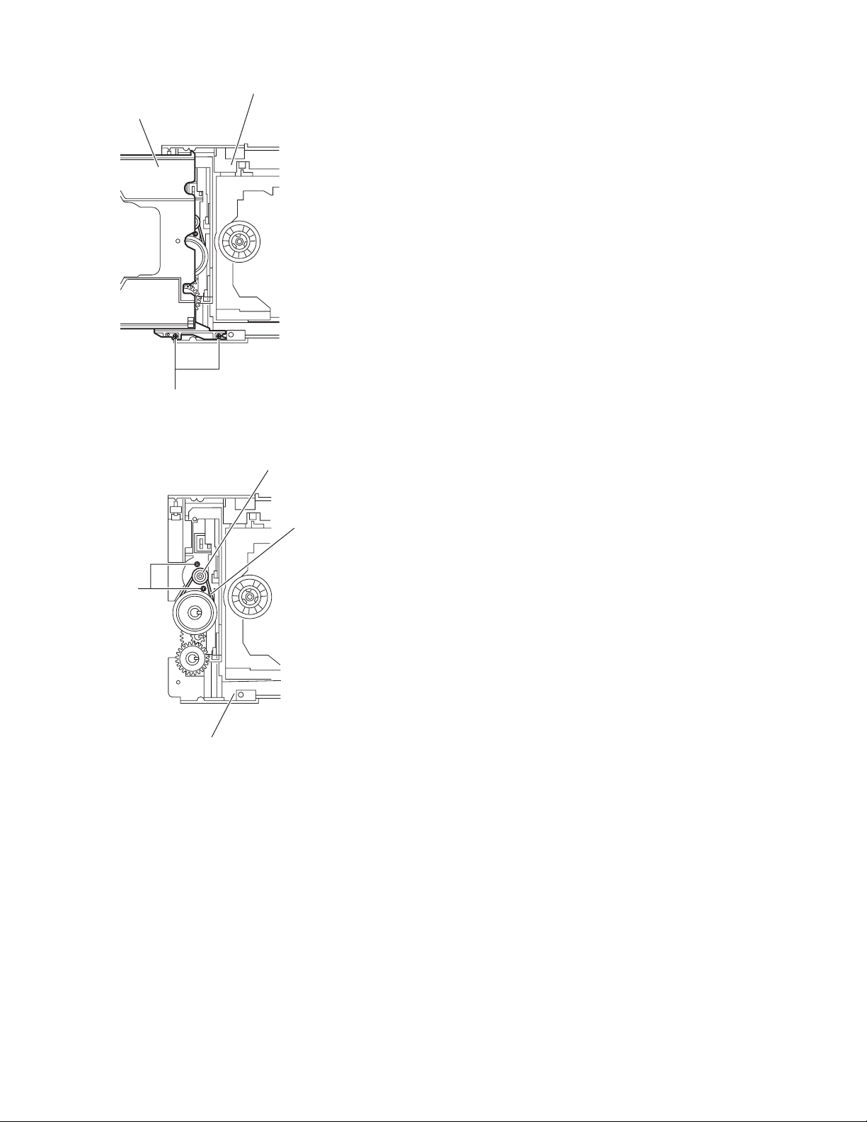
DVD mechanism assembly
Tray assembly
K
Fig.13
Motor pulley
M
DVD mechanism assembly
Fig.14
Belt
1-22 (No.MB413)
Page 23
SECTION 4
ADJUSTMENT
4.1 TH-S11 TEST MODE
This player has a TEST MODE for product QC, service or repair.
Contents as follows. If the DVD TRAY is not completely closed, supply AC power and press POWER ON to close the TRAY.
After confirm that the TRAY is completely closed go to standby.
Once LED lights up, pull off the power plug. Reinsert the AC power plug to the outlet while pressing,"POWER" and "STOP" button at
the front panel of the set.
TEST MODE has the 7 different steps. Press MENU key on the remote control to change the steps.
TEST MODE is canceled by the POWER key.
STEP 1:
RegionVersion
Version & Region explanation. Refer to next page.
Learn Status
Bit 0 - already learn DVD
Bit 1 - already learn CD
Bit 2 - already checked BCA area
Init Status
0x00 - normal init
0x01 - all init (above + FE)
0xFF - not yet init
STEP 2:
CPRM checksum (If Device key not input - FFFF)
STEP 3:
Sysyem
Version
STEP 4:
Indicator check mode. All FL segment light up.
STEP 5:
Mechanism check mode. In this mode player displays "CHECK".
STEP 6:
33E9K R
Rom
Correction
Version
Learn
Status
Unit
Init
Status
Region
0 - RF
1 - USA, Canada
2 - Europe, Middle East, Japan, South Africa
3 - S.Korea, Taiwan, HK, ASEAN
4 - Australia, NZ, Latin America
5 - Ex-Soviets, Indian sub-continent, Africa
6 - China
7 - Reserved
8 - International territory (airplanes, cruise ship, etc.)
Model type:
S11 or S33
STEP 7:
System micon version
S11B1935
Model
Name
Version and
tuner AM
step
Month:
1: Jan
2: Feb
:
:
A: Oct
B: Nov
Show R for RDS version or
blank for not RDS version
Day
Software
version
(No.MB413)1-23
Page 24

4.2 How to repair after carried out full-initialize
(1) Learning DVD
playback VT-501
(2) Learning CD
playback CTS-1000
(3) standby mode (push power key)
(4) Checking BCA
insert V-2805
test mode (press POWER and STOP button together during AC power plug in)
check mode (press menu key of remote controller)
BCA check (press +10 key of remote controller)
FL indication change "0000 0000" to "0000 0001" and Disc auto stop
(5) standby mode (push power key)
4.3 Rating Source, Region Code
Area Code
B/E/EN/EV AC230V 50Hz
EE
Video Signal
PAL
NTSC
J/C
UJ
US/UN
AC110,127,220,230-240V 50/60Hz
AC110,127,220,230-240V 50/60Hz
UB
UT
NTSC/PAL
AC110,127,220,230-240V 50/60Hz
UF/UFC
UW/UY
UX/UG
AC110,127,220,230-240V 50/60Hz
AC110,127,220,230-240V 50/60Hz
A
Rating Source
Rating Frequency
AC230V 50Hz
AC120V 60Hz
AC220V 50Hz
AC220V 50Hz
AC240V 50Hz
FL indicate of
Area Code in
Test mode
E
EE
JC
1U
3U
UB
UT
UF
4U
2U
4U
Region
Code
2
5
1
1
3
3
3
6
4
2
4
1-24 (No.MB413)
Page 25

SECTION 5
TROUBLESHOOTING
This service manual does not describe TROUBLESHOOTING.
(No.MB413)1-25
Page 26

Victor Company of Japan, Limited
AV & MULTIMEDIA COMPANY AUDIO/VIDEO SYSTEMS CATEGORY 10-1,1chome,Ohwatari-machi,Maebashi-city,371-8543,Japan
(No.MB413)
Printed in Japan
VPT
Page 27
DVD DIGITAL THEATER SYSTEM
SYSTÈME CINÉMA NUMÉRIQUE DVD
TH-S11
Consists of XV-THS11, SP-WS11, SP-THS11F,
SP-THS11C and SP-THS11S
Se compose de XV-THS11, SP-WS11,
SP-THS11F, SP-THS11C et SP-THS11S
Français English
INSTRUCTIONS
MANUEL D’INSTRUCTIONS
GVT0155-014B
[C]
Page 28
Warnings, Cautions and Others /Mises en garde, précautions et indications diverses
CAUTION
To reduce the risk of electrical shocks, fire, etc.:
1. Do not remove screws, covers or cabinet.
2. Do not expose this appliance to rain or moisture.
CAUTION— button!
Disconnect the mains plug to shut the power off completely
(the STANDBY lamp goes off).
The button in any position does not disconnect the mains
line.
• When the system is on standby, the STANDBY lamp lights
red.
• When the system is turned on, the STANDBY lamp goes off.
The power can be remote controlled.
IMPORTANT FOR LASER PRODUCTS
1. CLASS 1 LASER PRODUCT
CAUTION: Do not open the top cover. There are no
2.
user serviceable parts inside the unit; leave all
servicing to qualified service personnel.
CAUTION: Visible and invisible laser radiation when
3.
open and interlock failed or defeated. Avoid direct
exposure to beam.
4. REPRODUCTION OF LABEL: CAUTION LABEL,
PLACED INSIDE THE UNIT.
ATTENTION
Afin d’éviter tout risque d’électrocution, d’incendie, etc.:
1. Ne pas enlever les vis ni les panneaux et ne pas ouvrir le
coffret de l’appareil.
2. Ne pas exposer l’appareil à la pluie ni à l’humidité.
ATTENTION—Touche !
Déconnectez la fiche secteur pour mettre l’appareil
complètement hors tension (tous les témoins et toutes les
indications s’éteignent).
La touche dans n’importe quelle position ne déconnecte
pas l’appareil du secteur.
• Quand l’appareil est en mode de veille, le témoin
STANDBY est allumé en rouge.
• Quand l’appareil est sous tension, le témoin STANDBY
s’éteint.
L’alimentation ne peut pas être commandée à distance.
IMPORTANT POUR LES PRODUITS LASER
1. PRODUIT LASER CLASSE 1
2. ATT EN TI ON: N’ouvrez pas le couvercle supérieur. Il
n’y a aucune pièce réparable par l’utilisateur à
l’intérieur de l’appareil; confiez toute réparation à un
personnel qualifié.
3. ATT EN TI ON: Risque de radiations laser visible et
invisible quand l’appareil est ouvert ou que le systéme
de verrouillage ne fonctionne pas ou a été mis hors
service. Évitez toute exposition directe au rayon.
4. REPRODUCTION DE L’ÉTIQUETTE: ÉT QUETTE
DE PRÉCAUTION PLACÉE L’INTERIEUR DE
L’ AP PAR EI L.
G-1
Page 29
G-2
Page 30

Table of contents
Introduction .....................................2
Notes on handling .................................................................2
Supplied accessories ............................................................2
English
About discs .....................................3
Playable disc types ...............................................................3
Index of parts and controls ............5
Connections ....................................7
Connecting the FM and AM antennas ....................................7
Connecting the satellite (front, center, surround) speakers and
the subwoofer ......................................................................... 8
Speaker layout ......................................................................9
Connecting a TV ....................................................................9
Connecting an external component .......................................9
Connecting the power cord ...................................................9
Operating the TV ........................... 10
Basic operations ...........................11
Turning the system on/off ...................................................11
Selecting the source to play ................................................12
Adjusting the volume [VOLUME] ........................................12
Listening with headphones (not supplied) ..........................12
Turning off the sound temporarily [MUTING] .....................12
Adjusting the brightness of the indications [DIMMER] .......12
Sleep Timer [SLEEP] ...........................................................13
Adjusting the output level of the front/center/surround
speakers and subwoofer .....................................................13
Adjusting the sound ............................................................13
Changing the scan mode ....................................................13
Playback ........................................14
Basic playback ....................................................................14
One touch replay .................................................................16
Fast-forward/fast-reverse search ........................................16
Skip to the beginning of a desired selection .......................16
Locating a desired title/group using number buttons .........17
Selecting the desired title/playlist from the control display .....
17
Advanced operations ....................18
Using the surround mode ...................................................18
Using the on-screen bar .....................................................19
Playing from a specified position on a disc .........................21
Using the file control display ..............................................22
Resume playback ................................................................23
Selecting a view angle .........................................................23
Selecting the subtitle ..........................................................24
Selecting the audio .............................................................24
Special picture playback .....................................................25
Program playback ...............................................................26
Random playback ...............................................................26
Repeat playback ..................................................................27
Tray lock .............................................................................28
Balance setting ...................................................................28
Setting DVD preferences ..............29
Using the setup menus .......................................................29
Menu description ................................................................29
Tuner operations ........................... 32
Manual tuning .....................................................................32
Preset tuning ......................................................................33
Selecting the FM reception mode ........................................33
References ....................................34
Maintenance .......................................................................34
Troubleshooting ..................................................................34
Specifications .....................................................................35
1
Page 31

Introduction
Notes on handling
7 Important cautions
Installation of the system
• Select a place which is level, dry and neither too hot nor too cold;
between 5°C and 35°C.
• Leave sufficient distance between the system and the TV.
• Do not use the system in a place subject to vibration.
Power cord
• Do not handle the power cord with wet hands!
• A small amount of power is always consumed while the power
cord is connected to the wall outlet.
• When unplugging the power cord from the wall outlet, always
pull on the plug, not the power cord.
To prevent malfunctions of the system
• There are no user-serviceable parts inside. If anything goes
wrong, unplug the power cord and consult your dealer.
• Do not insert any metallic object into the system.
• Do not use any non-standard shape disc (like a heart, flower or
credit card, etc.) available on the market, because it may damage
the system.
• Do not use a disc with tape, stickers, or paste on it, because it
may damage the system.
7 Safety precautions
Avoid moisture, water and dust
Do not place the system in moist or dusty places.
Avoid high temperatures
Do not expose the system to direct sunlight and do not place it near
a heating device.
When you are away
When away on travel or for other reasons for an extended period of
time, disconnect the power cord plug from the wall outlet.
Do not block the vents
Blocking the vents may damage the system.
Care of the cabinet
When cleaning the system, use a soft cloth and follow the relevant
instructions on the use of chemically-coated cloths. Do not use
benzene, thinner or other organic solvents including disinfectants.
These may cause deformation or discoloring.
If water gets inside the system
Turn the system off and disconnect the power cord plug from the
wall outlet, then call the store where you made your purchase.
Using the system in this condition may cause fire or electrical
shock.
English
Label sticker
Sticker
Paste
Note about copyright laws
Check the copyright laws in your country before recording from the
discs. Recording of copyrighted material may infringe copyright
laws.
Note about copyguard system
The discs are protected by copyguard system. When you connect
the system to your VCR directly, the copyguard system activates
and the picture may not be played back correctly.
Supplied accessories
Check to be sure you have all of the supplied accessories.
The number in parentheses is the quantity of the pieces supplied.
If anything is missing, contact your dealer immediately.
• Remote control (1)
• Batteries (2)
• FM antenna (1)
• AM loop antenna (1)
• Composite Video cord (1)
2
Page 32

About discs
Playable disc types
This system has been designed to play back the following discs:
English
DVD VIDEO, Video CD (VCD), Super Video CD (SVCD), Audio
CD (CD), CD-R and CD-RW.
• This system accommodates the NTSC system, and also can play
discs recorded with PAL system.
• This system can also play finalized DVD-R/-RWs recorded in
DVD VIDEO format. However, some discs may not be played
because of their disc characteristics or recording conditions.
Discs you can play:
DVD VIDEO Audio CD
VCD SVCD
• The following discs cannot be played back:
CD-I (CD-I Ready), Photo CD, SACD, etc.
Playing back these discs will generate noise and damage the
speakers.
• The Non-DVD side of a “DualDisc” does not comply with the
“Compact Disc Digital Audio” standard. Therefore, the use of
Non-DVD side of a DualDisc on this product may not be
recommended.
• On some DVD VIDEOs, VCDs or SVCDs, their actual
operation may be different from what is explained in this
manual. This is due to the disc programming and disc
structure, not a malfunction of this system.
Region code of DVD VIDEO
DVD VIDEO players and DVD VIDEO discs have their own
Region Code numbers. This system can play back DVD VIDEO
discs whose Region Code numbers include the system’s Region
Code, which is indicated on the rear panel.
• Example of playable DVD:
ALL
If a DVD with an improper Region Code number is loaded,
“REGION CODE ERROR!” appears on the TV screen and
playback cannot start.
Notes on DVD-R, DVD-RW and DVD-RAM
• This system can also play finalized DVD-Rs or DVD-RWs
recorded in DVD VIDEO format and DVD-RWs or DVD-RAMs
recorded in DVD VR format.
• This system can also play DVD-Rs or DVD-RWs if MP3 and
JPEG files are recorded on them with UDF Bridge format.
This system does not support “multi-border” disc.
Notes on CD-R and CD-RW
• This system can also play CD-Rs or CD-RWs if MP3 and JPEG
files are recorded on them with ISO 9660 format.
• This system supports “multi-session” discs (up to 20 sessions).
• This system cannot play “packet write” discs.
Some discs may not be played back because of their disc
characteristics, recording conditions, or damage or stain on them.
1
1
21
423
DVD Logo is a trademark of DVD Format/Logo Licensing
Corporation.
3
Page 33

About discs
For all playable files
• The system can only recognize and play files with one of the
following extensions, which can be in any combination of upper
and lower case;
MP3: “.MP3”, “.mp3”
JPEG: “.JPG”, “.JPEG”, “.jpg”, “.jpeg”
• The system recognizes up to 150 tracks (files) per group, 99
groups per disc, and the total number of the tracks (files) that the
system can play is 4000.
• Some files may not be played back normally because of their disc
characteristics or recording conditions.
• MP3/JPEG discs require a longer readout time. (It differs due to
the complexity of the directory/file configuration.)
• If different kinds of the file are mixed on a disc, set the FILE
TYPE setting in the PICTURE menu to the appropriate setting
for the data to be read (“AUDIO” or “STILL PICTURE”). (See
page 30.)
Notes on MP3 files
• Tag information (album name, artist name, and track name) can
be shown on the TV. (See page 22.)
• The system can play back the MP3 files recorded at 32 kbps to
320 kbps as a bit rate, and at 16 kHz, 22.05 kHz, 24 kHz, 32 kHz,
44.1 kHz and 48 kHz as a sampling frequency.
• We recommend to record each piece of material (song) at a
sample rate of 44.1 kHz and at a data transfer rate of 128 kbps.
Notes on JPEG files
• We recommend to record a file at 640 x 480 resolution. (If a file
has been recorded at a resolution of more than 640 x 480, it will
take a longer time to be displayed.)
• This system can only play baseline JPEG files.
English
This product incorporates copyright protection technology that is
protected by U.S. patents and other intellectual property rights. Use
of this copyright protection technology must be authorized by
Macrovision, and is intended for home and other limited viewing
uses only unless otherwise authorized by Macrovision. Reverse
engineering or disassembly is prohibited.
4
Page 34

Index of parts and controls
The numbers in the figures indicate the pages where the details of the parts are described.
Front panel (center unit)
English
Display window
19 32 15 19
P L PCM SURR
WMA
MP3 AAC RESUME
PROGRESSIVE B.S.P. CHAP. TRK PG P L BONUS ST RDS TA NEWS INFO PRG RND
15 32
Disc tray (inside): 14
Rear panel (center unit)
FM AM
23 272613
CH
15
15
15
0
14
STANDBY
11
Remote sensor: 6
MONO
33
11
73
14 14
14
26
MHz
kHz
16
/ TUNING /
16
SOURCE
12
PHONES
12
VOLUME
12
9
9
87
9
5
Page 35

Index of parts and controls
Remote control Putting batteries in the remote control
STANDBY/ON
REPEAT
27
27
Number
buttons:16
12
17, 21, 29
15
12, 14
14, 33
16, 32
16, 32
12, 32
12
17
26
13, 25
13
0, 12, 13,
3, 25, 27,
28, 29
13
A-B RPT SLEEP
1
4
7
DIMMER
10 0
TOP MENU/PG MENU/PL
SET UP SETTING
FL DISPLAY
DVD/CD MEMORY FM MODE
TUNING SLOW
FM/AM AUX
TITLE/
PLAY MODE CANCEL
GROUP
BASS/
TREBLE
SCAN MODE
VFP
SHIFT SPK-LEVEL
DVD THEATER SYSTEM
REMOTE CONTROL RM-STHS33J
2
5
8
ENTER
TV CHANNEL
3
6
TV/VIDEO
9
SURROUND
10
ON SCREEN
ANGLE
SUBTITLE
AUDIO
LEVEL AUDIO VOL
TV
RETURN
ZOOM
MUTING
TV VOL
11
13
10
10
19
17, 21,
28
13, 17,
29
19
16, 21
14, 33
16, 25
16, 25
24, 25
23, 24
12
26
10, 12
10, 13
R6P (SUM-3)/AA (15F) type dry-cell batteries (supplied)
If the range or effectiveness of the remote control decreases,
replace both batteries.
CAUTION
• Do not expose batteries to heat or flame.
Operating the system from the remote
control
Aim the remote control directly to the front panel of the center unit.
• Do not hide the remote sensor.
English
6
Page 36

Connections
Connecting the FM and
English
AM antennas
7 AM loop antenna
Setting up supplied AM loop antenna
Do not connect the power cord until all other connections have been made.
If reception is poor
Center unit
AM loop antenna
Outdoor single vinyl-covered wire
antenna (not supplied)
If the antenna cord is covered with the insulation
coat, twist and pull the insulation coat off and
remove.
Connecting AM loop antenna
1
2
Antenna cord
3
7 FM antenna
Center unit
If reception is poor
Center unit
Standard type (75 C
coaxial) connector
NOTE
• We recommend that you use coaxial cable for the FM antenna as it is
well-shielded against interference.
FM antenna (supplied)
Extend the supplied FM antenna
horizontally.
Outdoor FM antenna
(not supplied)
Outdoor FM antenna cord
(not supplied)
• Turn the loop antenna until you have the best reception during
AM broadcast program reception.
NOTE
• Make sure the antenna conductors do not touch any other terminals,
connecting cords and power cords. This could cause poor reception.
7
Page 37

Connections
Do not connect the power cord until all other connections have been made.
Connecting the satellite (front, center, surround)
speakers and the subwoofer
English
Front speakers
Center speaker
Speaker cord
• Connect the black cords to the black (-) terminals.
• Connect the white cords to the red (+) terminals.
Before connecting
the speaker cords;
Twist and pull the
insulation coat off
and remove.
Subwoofer
Surround speakers
CAUTION
• When you connect speakers other than the supplied ones, use
speakers of the same speaker impedance (SPEAKER IMPEDANCE)
indicated on the rear of the center unit.
• DO NOT connect more than one speaker to one speaker terminal.
• When installing the satellite speakers on the wall;
• Be sure to have them installed on the wall by a qualified personnel.
DO NOT install the satellite speakers on the wall by yourself to
avoid unexpected damage from their falling off the wall due to
incorrect installation or weakness in wall structure.
• Care must be taken in selecting a location for speaker installation
on a wall. Injury to personnel or damage to equipment may result
if the speakers installed interfere with daily activities.
8
Page 38

Connections
Speaker layout
Do not connect the power cord until all other connections have been made.
7 To connect a TV equipped with the S-VIDEO and/or
the composite video input jacks
English
Front left
speaker
NOTE
• Place the satellite speakers on a flat and level surface.
• The front and center speakers are magnetically shielded to avoid color
distortions on TVs. However, if not installed properly, they may
cause color distortions. So, pay attention to the following when
installing the speakers.
– When placing the speakers near a TV set, turn off the TV’s main
power switch or unplug it before installing the speakers. Then wait
at least 30 minutes before turning on the TV’s main power switch
again.
Some TVs may still be affected even though you have followed the
above. If this happens, move the speakers away from the TV.
• The surround speakers and the subwoofer are not magnetically
shielded.
If it is located nearby the TV or monitor, it will probably cause
color distortion on the screen. To avoid this, do not place the
speaker nearby the TV or monitor.
• Be sure to place the subwoofer to the TV’s right. If you place the
subwoofer to the TV’s left, keep sufficient distance between them to
prevent the TV screen from appearing mottled.
Center speaker
Surround left
speaker
Front right
speaker
Subwoofer
Surround right
speaker
Connecting a TV
Center unit
NOTE
• Select the appropriate scan mode according to your TV. (See page
13.)
S-VIDEO cord
(not supplied)
Composite video cord
(supplied)
TV
Connecting an external
component
You can enjoy the sound of an analog component.
Center unit
RCA pin plug cord
(not supplied)
NOTE
• If you connect a sound-enhancing device such as a graphic equalizer
between the source components and this system, the sound output
through this system may be distorted.
• When playing a video component such as a VCR;
• To listen to the sound, select “AUX” as the source to play. (See
page 12.)
• To see the picture, connect the video output jack of the component
to the video input jack of the TV directly, and select the correct
input mode on the TV.
To audio output
VCR
TV
Cassette recorder
• Distortion of picture may occur when connecting the TV via a
VCR, or to a TV with a built-in VCR.
• You need to set “MONITOR TYPE” in the PICTURE menu
correctly according to the aspect ratio of your TV. (See page 30.)
7 To connect a TV equipped with the component video
input jacks
Center unit
Component video cord (not supplied)
NOTE
• If your TV supports progressive video input, you can enjoy a high
quality picture by setting the progressive scan mode to active. (See
page 13.)
• If the component video input jacks of your TV are of the BNC type,
use a plug adapter (not supplied) to convert the pin plugs to BNC
plugs.
• The video signals can be output only when you select “DVD” as the
source to play. (See page 12.)
To component
TV
video input
9
Connecting the power
cord
Make sure that all other connections have been completed.
Center unit
Power cord
CAUTION
• Disconnect the power cord before cleaning or moving the system.
• Do not pull on the power cord to unplug the cord. When unplugging
the cord, always grasp and pull the plug so as not to damage the cord.
NOTE
• Preset settings, such as preset stations and surround mode adjustment,
may be erased in a few days in the following cases;
• If you unplug the power cord of the center unit.
• If a power failure occurs.
Plug into AC outlets.
Page 39

Operating the TV
You can use the remote control to operate not only this unit but also JVC’s TV.
• Refer also to the manuals supplied for the TV.
• To operate the TV, aim the remote control directly at the remote sensor on the TV.
7 To operate a JVC’s TV
You can perform the following operations on the TV.
English
REPEAT
A-B RPT SLEEP
1
2
4
5
8
7
DIMMER
10 0
TOP MENU/PG MENU/PL
SET UP SETTING
FL DISPLAY
DVD/CD MEMORY FM MODE
TUNING SLOW
FM/AM AUX
TITLE/
GROUP
PLAY MODE CANCEL
BASS/
TREBLE
SCAN MODE
VFP
SHIFT SPK-LEVEL
DVD THEATER SYSTEM
REMOTE CONTROL RM-STHS33J
3
6
9
10
ENTER
ANGLE
AUDIO
TV CHANNEL
LEVEL AUDIO VOL
STANDBY/ON
SURROUND
ON SCREEN
SUBTITLE
TV
TV/VIDEO
RETURN
ZOOM
MUTING
TV VOL
TV :
TV VOL +/– with SHIFT
pressed and held:
TV/VIDEO:
CHANNEL +/– with SHIFT
pressed and held:
Turn on or off the TV.
Adjust the volume.
Set the input mode
(either TV or VIDEO).
Change the channels.
10
Page 40

Basic operations
The buttons on the remote control are used to explain most of the
operations in this manual. You can use the buttons on the center
unit same as on the remote control for operations unless
English
otherwise noted.
The buttons described below are used on
pages 11 to 13.
REPEAT
A-B RPT SLEEP
1
2
5
4
8
7
DIMMER
10 0
TOP MENU/PG MENU/PL
SET UP SETTING
FL DISPLAY
DVD/CD MEMORY FM MODE
TUNING SLOW
FM/AM AUX
TITLE/
PLAY MODE CANCEL
GROUP
BASS/
TREBLE
SCAN MODE
VFP
SHIFT SPK-LEVEL
DVD THEATER SYSTEM
REMOTE CONTROL RM-STHS33J
3
6
9
10
ENTER
ANGLE
AUDIO
TV CHANNEL
LEVEL AUDIO VOL
STANDBY/ON
TV
TV/VIDEO
SURROUND
ON SCREEN
RETURN
ZOOM
SUBTITLE
MUTING
TV VOL
Turning the system on/off
On the remote control:
Press STANDBY/ON .
On the center unit:
Press .
When DVD is selected as the source (see page 12), the following
messages will appear on the TV screen.
• “OPEN”/“CLOSE”:
Appears when opening or closing the disc tray.
• “NOW READING”:
Appears when the system is reading the disc information.
• “REGION CODE ERROR!”:
Appears when the Region Code of the DVD VIDEO does not
match the code the system supports. The disc cannot be
played back.
• “NO DISC”:
Appears when no disc is loaded.
• “CANNOT PLAY THIS DISC”:
Appears when unplayable disc is loaded.
NOTE
• The STANDBY lamp goes off when the power is turned on, and the
lamp lights when the power is turned off.
• A small amount of the power is consumed even when the power is
turned off. This is called standby mode and the STANDBY lamp
lights in this mode. Unplug the power cord from the AC outlet to turn
the power off completely.
• You can also turn on the system by pressing the following buttons;
• 0 on the center unit
• One of the source selecting buttons on the remote control
• 3 on the center unit.
11
Page 41

Basic operations
See page 11 for button locations.
Selecting the source to
play
On the remote control:
Press one of the source selecting buttons
(DVD/CD3, FM/AM or AUX).
DVD/CD3: To play back a disc (DVD VIDEO, VCD etc.). (See
page 14.)
FM/AM: To tune in an FM or AM station. (See page 32.)
Each time you press the button, the band alternates
between FM and AM.
AUX: To select the external component connected to the
center unit. (See page 9.)
On the center unit:
Press SOURCE repeatedly until the source
name you want appears on the display
window.
NOTE
• When a source except DVD is selected, this system does not output
video signals.
• It may take time to change the source.
Adjusting the volume
[VOLUME]
Listening with headphones
(not supplied)
CAUTION
Be sure to turn down the volume;
• Before connecting or putting on headphones as high volume may
damage both the headphones and your hearing.
• Before disconnecting headphones as high volume may be suddenly
output from the speakers.
While connecting a pair of headphones to the PHONES jack on the
center unit, the system automatically cancels the surround mode
(see page 18) currently selected, deactivates the speakers, and
activates the headphone mode. “H.PHONE” appears on the display
window.
Headphone mode
When using the headphones, the following signals are output
regardless of your speaker setting;
• For 2 channel sources, the front left and right channel signals are
output from the headphones.
• Multi-channel signals are down-mixed and output from the
headphones.
Turning off the sound
temporarily [MUTING]
Press MUTING.
English
CAUTION
• Always set the volume to minimum level before starting any source.
If the volume is set at its high level, the sudden blast of sound could
permanently damage your hearing and/or blow out the speakers.
On the remote control:
Press AUDIO VOL +/–.
On the center unit:
Turn VOLUME.
To restore the sound
Perform one on the following:
• Press MUTING again.
• Press AUDIO VOL +/– (or turn VOLUME on the center unit).
Adjusting the brightness
of the indications
[DIMMER]
Press DIMMER, with SHIFT pressed.
Each time you repeat the procedure, the brightness level changes.
12
Page 42

Basic operations
See page 11 for button locations.
Sleep Timer [SLEEP]
The system turns off automatically when the specified period of
English
time has passed.
Press SLEEP, with SHIFT pressed.
Each time you repeat the procedure, the shut-off time changes.
Example:
minutes
SL
EE
To check the remaining time
Press SLEEP, with SHIFT pressed once.
To change the remaining time
Press SLEEP repeatedly, with SHIFT pressed.
To cancel
Press SLEEP repeatedly, with SHIFT pressed until “SLEEP - -”
appears.
• Turning off the power also cancels the Sleep Timer.
60
P
Adjusting the output level
of the front/center/
surround speakers and
subwoofer
1 Press SPK-LEVEL to show the target
speaker indication on the display
window.
Each time you press the button, the indication of the speakers
changes as follows:
FRONTL Z FRONTR Z CENTER Z
SURR(surround) L
SUBWFR
Z (back to the beginning)
Z SURR(surround) R Z
2 Press LEVEL +/– to adjust the output
level from -6 to 6.
Adjusting the sound
1 Press BASS/TREBLE to show “BASS”
or “TREBLE” on the display window.
Each time you press the button, the indication alternates
between “BASS” and “TREBLE”.
2 Press LEVEL +/– to adjust the level from
-8 to 8.
NOTE
• The adjustments take effect for all sources.
Changing the scan mode
The system can be accommodated to your TV’s scan mode.
• To use the system in progressive mode, it is required that the
center unit is connected to the TV using a component video cord
(not supplied) in advance. (See page 9.)
7 While DVD is selected as the source and before playback
1 Press and hold SCAN MODE for
2 seconds, with SHIFT pressed.
The current setting appears on the display window.
2 Press Cursor 3/2 to select the desired
mode.
• INTER,: Select when your TV supports the
interlaced video input only.
• PROGRESS: Select when your TV equipped with
component jacks supports the progressive
video input.
You can get better picture quality in the order —
“PROGRESS” > S-video > Composite.
3 Press ENTER while the selected mode
is displayed.
When “PROGRESS” is selected, the PROGRESSIVE
indicator lights on the display window.
NOTE
• Although the picture may be distorted when you press ENTER, this
is not a malfunction of the system.
NOTE
• You can also make adjustments by using the setup menu shown on the
TV screen. (See page 31.)
• The adjustments take effect for all sources.
13
• There are some progressive TVs and High-Definition TVs that are
not fully compatible with this system, resulting in an unnatural
picture when playing back a DVD VIDEO in the progressive scan
mode. In such a case, change the scan mode to “INTER,”.
To check the compatibility of your TV, contact your local JVC
customer service center.
• All JVC progressive TVs and High-Definition TVs are fully
compatible with this system.
Page 43

Playback
• The mark shows the types of discs the operation is available
for.
The buttons described below are used on pages 14 to 17.
3
6
9
10
ENTER
ANGLE
AUDIO
TV CHANNEL
LEVEL AUDIO VOL
STANDBY/ON
TV
TV/VIDEO
SURROUND
ON SCREEN
RETURN
ZOOM
SUBTITLE
MUTING
TV VOL
Number
buttons
REPEAT
A-B RPT SLEEP
1
2
5
4
8
7
DIMMER
10 0
TOP MENU/PG MENU/PL
SET UP SETTING
FL DISPLAY
DVD/CD MEMORY FM MODE
TUNING SLOW
FM/AM AUX
TITLE/
GROUP
PLAY MODE CANCEL
BASS/
TREBLE
SCAN MODE
VFP
SHIFT SPK-LEVEL
DVD THEATER SYSTEM
REMOTE CONTROL RM-STHS33J
Basic playback
1 Press 0 on the
center unit.
• The system turns on and the
disc tray comes out.
2 Place a disc.
When placing an 8 cm
Label side up
(3 inches) disc
3 Press DVD/CD3 (play button).
For MP3
The file control display (see page 22) appears on the TV screen.
For JPEG
Each file (still pictures) is shown on the TV screen for about 3
seconds (slide-show). When stopping playback, the file control
display (see page 22) appears on the TV screen.
For DVD VR disc
Pressing TOP MENU/PG or MENU/PL shows the control display
on the TV screen (see page 17).
7 To pause
Press 8.
To return to playback, press 3 (play button).
English
7 To stop
Press 7.
7 On-screen guide icons
During DVD VIDEO playback, the following guide icons may
appear for a while on the TV screen;
• : appears at the beginning of a scene containing multisubtitle languages.
• : appears at the beginning of a scene containing multi-audio
languages.
• : appears at the beginning of a scene containing multi-angle
views.
• (Play), (Pause), / (Fast forward/
fast-reverse), / (Slow-motion forward/
reverse): appears when you perform each operation.
• : the disc cannot accept an operation you have tried to do.
NOTE
• (For JPEG) The system cannot accept operations even though you
press any buttons before the entire picture appears on the TV screen.
• If you do not want the on-screen guide icons to appear, see page 31.
14
Page 44

Playback
See page 14 for button locations.
7 Playback information on the display window
DVD VIDEO
Example:
English
When a DVD VIDEO encoded with Dolby Digital 5.1ch is played
Elapsed playing time
Chapter number
SURR
2
Signal and speaker indicators (See page 19.)
Surround mode and digital signal format (See page 19.)
Pressing FL DISPLAY
Title number
T
SURR
DVD VR disc
Example:
During playback on the Original program*
Title number
1
4
.
1
5
.
Elapsed playing time
(hour:minute:second)
(hour:minute:second)
3
::
3
2
C
1
Chapter number
2
4
VCD/SVCD/CD
Example:
When a CD is played back
Track number
LPCM
NOTE
• When a VCD or SVCD with PBC function is played, the elapsed
playing time does not appear, but “PBC” appears.
MP3 file
MP3
MP3 indicator
Pressing FL DISPLAY
1
2
.
Elapsed playing time (minute:second)
Track number
2
Elapsed playing time (minute:second)
Group number
3
.
Signal and speaker
3
3
:
1
Signal and speaker
:
3
11
4
2
(during playback only)
indicators
indicators
22
.
2/
PG (Original program) indicator
Pressing FL DISPLAY
Title number
G
P
Example:
During playback on the Playlist*
Title number
0
3
.
PL
PL (Playlist) indicator
Pressing FL DISPLAY
Playlist number
L
P
00::263
Chapter number
1C 3
.
Elapsed playing time
(hour:minute:second)
00::503
Chapter number
1C 1
.
2
2
1
MP3
JPEG file
Pressing FL DISPLAY
NOTE
• You can change the time information mode (except for MP3/JPEG).
(See page 20.)
• You can also check the playback information on the TV screen. (See
page 19.)
G
File number
1
2
Group number
G
1
T
.
Track number
3
.
2
.
1
J
E
P
File number
1
F
2
3
G
3
* Pressing TOP MENU/PG or MENU/PL, you can change the
play mode. (See page 17.)
15
Page 45

Playback
7 Screen saver
A TV screen may burn out if a static picture is displayed for a long
time. To prevent this, the system automatically dims the screen if a
static picture is displayed for over 5 minutes (the screen saver
function).
• Pressing any button will cancel the screen saver function.
• If you do not want to use the screen saver function, see page 30.
One touch replay
You can move back the playback position by
10 seconds from the current position.
7 During playback
On the remote control:
Press .
NOTE
• This function works in the same title.
• This feature may not work for some discs.
See page 14 for button locations.
Fast-forward/fast-reverse
search
7 During playback
On the remote control:
Press y or 1.
Each time you press the button, the
search speed changes (x2, x5, x10,
x20, x60).
To return to normal speed playback
Press DVD /CD
On the center unit:
Press and hold x or 4.
Continuously pressing x or 4 increases the fast-forward/
reverse search speed (x5=x20).
NOTE
• When a DVD VIDEO, DVD VR, VCD or SVCD is played back, no
sound comes out during fast-forward/reverse search.
• When a CD is played back, sound is intermittent and low during fast-
forward/reverse search.
• This feature may not work for some discs.
• For MP3,
3 (play button).
the search speed is not shown.
English
Skip to the beginning of a
desired selection
7 Using x / 4 buttons
7 For DVD VIDEO/DVD VR
(chapter): During playback
For VCD/SVCD (track):
During playback without PBC function
For CD/MP3/JPEG (track/file): During playback or while
stopped
Press x or 4 repeatedly.
NOTE
• When playing back an MP3/JPEG, you can make operations using the
file control display. (See page 22.)
• This feature may not work for some discs.
7 Using number buttons on the remote control
7 For DVD VIDEO/DVD VR (title, chapter):
While stopped, the title number is selected.
During playback, the chapter number is selected.
For VCD/SVCD (track):
During playback without PBC function
For CD/MP3/JPEG (track/file):
During playback or while stopped
Press number buttons (0-10, +10) to select
the desired number.
• For details on using the number buttons, see “How to use the
number buttons” below.
How to use the number buttons
To select 3: Press 3.
To select 14: Press +10, then 4.
To select 24: Press +10 twice, then 4.
To select 40: Press +10 three times, then 10.
Or press +10 four times, then 0.
16
Page 46

Playback
See page 14 for button locations.
Locating a desired title/
English
group using number
buttons
7 During playback or while stopped.
1 Press TITLE/GROUP.
“_ _” or “_” is shown in the title/group
display area in the display window.
Example:
During DVD VIDEO playback
__
.
::
3
1
2
5
4
2 While the display window shows “_ _”
or “_”, use number buttons (0-10, +10)
to enter the desired title or group
number.
The system starts playback from the first chapter/track/file of
the selected title/group.
• For details on using the number buttons, see “How to use the
number buttons”. (See page 16.)
NOTE
• This feature may not work for some discs.
Selecting the desired
title/playlist from the
control display
7 During playback or while stopped.
1 Press TOP MENU/PG or MENU/PL.
The control display is shown on the TV screen, and the system
starts playback of the first title/playlist.
• The PLAY LIST is shown only when the playlist is on the
DVD VR disc.
TOP MENU/PG: shows the ORIGINAL PROGRAM.
Example:
*1: Title number
*2: Recording date
*3: Recording source (TV station, the input terminal of the
recording equipment etc.)
*4: Start time of recording
*5: Title of the original program/playlist (The title may not be
displayed depending on the recording equipment.)
*6: Current title
MENU/PL: shows the PLAY LIST.
Example:
*7: Playlist number
*8: Creating date of playlists
*9: Number of chapters
*10:Total playing time
*11:Current playlist
2 Press Y/5 to select the desired title/
playlist.
The system starts playback of the selected title/playlist.
To clear the control display
• Press ENTER.
About the play mode on a DVD VR disc
• Original program (ORIGINAL PROGRAM):
The system can play back the original picture in the recorded
order.
• Playlist (PLAY LIST):
The system can play back the playlist edited by the recording
equipment.
17
Page 47

Advanced operations
• The mark shows the types of discs the operation is available
for.
The buttons described below are used on pages 18 to 28.
3
6
9
10
ENTER
ANGLE
AUDIO
TV CHANNEL
LEVEL AUDIO VOL
STANDBY/ON
TV
TV/VIDEO
SURROUND
ON SCREEN
RETURN
ZOOM
SUBTITLE
MUTING
TV VOL
Number
buttons
Cursor
(3/2/Y/5)/
ENTER
REPEAT
A-B RPT SLEEP
1
2
4
5
8
7
DIMMER
10 0
TOP MENU/PG MENU/PL
SET UP SETTING
FL DISPLAY
DVD/CD MEMORY FM MODE
TUNING SLOW
FM/AM AUX
TITLE/
GROUP
PLAY MODE CANCEL
BASS/
TREBLE
SCAN MODE
VFP
SHIFT SPK-LEVEL
DVD THEATER SYSTEM
REMOTE CONTROL RM-STHS33J
Using the surround mode
7 Auto Surround (AUTO SURR)
This function automatically selects the appropriate surround mode
according to the input signals. For example, a multichannel source
is automatically reproduced in multichannel audio.
7 Dolby Surround
Dolby Pro Logic II*
Dolby Pro Logic II has a developed multichannel playback format
to decode all 2 channel sources — stereo source and Dolby
Surround encoded source — into a 5.1 channel.
Dolby Pro Logic II has two modes — Movie mode and Music
mode:
• Pro Logic II Movie (MOVIE)
Suitable for reproduction of Dolby Surround encoded sources
bearing the mark .
• Pro Logic II Music (MUSIC)
Suitable for reproduction of any 2 channel stereo music sources.
Dolby Digital*
Used to reproduce multichannel soundtracks of the software
encoded with Dolby Digital ( ).
7 DTS Digital Surround*
Used to reproduce multichannel soundtracks of the software
encoded with DTS Digital Surround ( ).
DTS Digital Surround (DTS) is another discrete multichannel
digital audio format available on CD and DVD software.
1
1
2
English
Available Surround modes for each input signal
The B marks show available surround modes.
Signal
Dolby Digital
(Multichannel)
Dolby Digital
(2 channel)
DTS Digital
Surround
(Multichannel)
DTS Digital
Surround
(2 channel)
Analog or Linear
PCM
Mode
Surround
off
SURR
OFF
Auto
Surround
AUTO
SURR
Dolby Surround
MOVIE*3MUSIC*
BB——B ——
BBBB—— B
BB——— B —
BBBB—— B
BBBB—— B
3
Dolby
Digital
DTS Digital
Surround
DTS ALL ST*
DSP
*1
Manufactured under license from
Dolby Laboratories. “Dolby”,
“Pro Logic”, and the double-D
3
symbol are trademarks of Dolby
Laboratories.
*2
“DTS” and “DTS Digital
Surround” are registered
trademarks of Digital Theater
Systems, Inc.
*3
You can select these modes by
pressing SURROUND. (See
page 19.)
Continued on next page
18
Page 48

Advanced operations
See page 18 for button locations.
7 All Channel Stereo
All Channel Stereo (ALL ST) mode can reproduce a larger stereo
sound field using all the connected (and activated) speakers.
All Channel Stereo can be used while reproducing 2 channel stereo
English
source.
Normal stereo sound All Channel Stereo
7 Indicators on the display window
Digital signal format indicators
LPCM, SURR: Lights when Linear PCM signal comes in.
GD, SURR: Lights when Dolby Digital signals come in.
C, SURR: Lights when DTS Digital (Surround) signals
come in.
No indication: No digital signal indicator lights when analog
signals come in.
Dolby Surround mode indicators
GPLII: Lights when Dolby Pro Logic II mode is activated.
Source signal indicators, etc.
Light to indicate the incoming signals.
a: Lights when the front left channel signal
comes in.
b: Lights when the center channel signal comes in.
c: Lights when the front right channel signal comes in.
d: Lights when the LFE channel signal comes in.
g: Lights when the surround left channel signal comes in.
i: Lights when the surround right channel signal comes in.
h: Lights when the monaural surround channel signal or 2
channel Dolby Surround signal comes in.
SW : Always lights.
The channel with “ ” shows that the corresponding speakers are
reproducing the channels’ sound.
If the channels’ sound decoded into 5.1 channel is reproduced, only
“ ” lights.
7 When playing back 2 channel source
You can select either mode of Dolby Pro Logic II (MOVIE/
MUSIC) or the DSP (ALL ST) mode.
Press SURROUND repeatedly to select the
desired mode.
The surround mode is turned on and the current surround mode
appears on the display window.
Each time you press the button, the surround mode changes.
For details on each mode, see page 18.
To turn off the surround mode
Press SURROUND repeatedly until “SURR
OFF” appears on the display window.
Storing adjustments — auto memory
When you turn the power off, the system memorizes the current
surround mode. The memorized mode is automatically recalled
when you turn the power on.
Using the on-screen bar
You can check disc information and you can use some functions
using the on-screen bar.
Showing the on-screen bar
7 Whenever a disc is loaded
Press ON SCREEN.
Each time you press the button, the onscreen bar changes as follows on the TV
screen.
Example:
During DVD VIDEO playback
Selecting the surround mode
The system is set up to automatically select the optimal surround
mode for input signal from digital multichannel software.
When playing back 2 channel source, you can select the desired
surround mode manually.
NOTE
• This function also takes effect for the sources other than DVD.
• For FM/AM and AUX, you can select All Channel Stereo (ALL ST)
or SURR OFF.
7 When playing back digital multichannel software
(except during SURR OFF mode)
The appropriate multichannel surround mode (Dolby Digital, DTS
Digital Surround or Linear PCM) is automatically selected.
19
(The on-screen bar disappears)
OFF
(back to the beginning)
• The currently selected item shows green.
Page 49

Advanced operations
See page 18 for button locations.
7 Contents of the on-screen bar during playback
DVD VIDEO
DVD VR disc
VCD
SVCD
CD
F Shows playback status.
: appears during playback.
/ : appears during fast forward/reverse.
/ : appears during playback in forward slow-motion/
reverse slow-motion.
: appears when paused.
: appears when stopped.
G Select this to change time information (E). See “Changing the
time information”.
H Select this for Repeat Playback. (See page 27.)
I Select this for time search function. (See page 22.)
J Select this for chapter search function. (See page 21.)
K Select this to change audio language, channel, or stream. (See
page 24.)
L Select this to change subtitle language. (See page 24.)
M Select this to change view angle. (See page 23.)
N Shows Playback Mode status.
PROGRAM: appears during Program Playback. (See page 26.)
RANDOM: appears during Random Playback. (See page 26.)
Changing the time information
You can change the time information in the
on-screen bar on the TV screen and the
display window of the center unit.
7 During playback
1 Press ON SCREEN twice.
The on-screen bar appears on the TV screen.
English
A Shows disc type.
B Shows audio information.
C Shows current title number.
D Shows current chapter number (for DVD VIDEO and DVD VR)
or track number (for other type of discs).
E Shows time information. See “Changing the time information”.
2 Press Cursor 3/2 to highlight .
3 Press ENTER repeatedly to select the
desired information.
Example:
When elapsed playing time of disc is selected.
7 VCD/SVCD/CD
• TIME: Elapsed playing time of current track
• REM: Remaining time of current track
• TOTAL: Elapsed time of disc
• T. REM: Remaining time of disc
7 DVD VIDEO/DVD VR
• TIME: Elapsed playing time of current chapter
• REM: Remaining time of current chapter
• TOTAL: Elapsed time of Title/Program
• T. REM: Remaining time of Title/Program
4 Press ON SCREEN.
The on-screen bar disappears.
NOTE
• When playing back DVD VR, “TIME” and “REM” cannot be shown.
20
Page 50

Advanced operations
Playing from a specified
English
position on a disc
You can start playing a title, chapter or track you specify. You can
also play a disc from specified time.
Locating a desired scene from the DVD
menu
DVD VIDEOs generally have their own menus which show
disc contents and you can display them on the TV screen.
You can locate a desired scene by using these menus.
7 Whenever a DVD VIDEO is loaded
1 Press TOP MENU/PG or MENU/PL.
The menu appears on the TV screen.
Example:
See page 18 for button locations.
2 Press number buttons (1-10, +10) to
select the number of the desired item.
• For details on using the number buttons, see “How to use the
number buttons”. (See page 16.)
To return to the menu
Press RETURN repeatedly until the menu screen appears.
When “NEXT” or “PREVIOUS” is shown on the TV
screen:
• To go to the next page, press x.
• To return to the previous page, press 4.
NOTE
• If you want to play a PBC-compatible VCD/SVCD without using the
PBC function, perform any of the following:
• Start playback by pressing number buttons while stopped.
• Press x repeatedly until the desired track number is displayed,
then start playback by pressing 3 (play button).
The track number appears on the display window instead of
“PBC”.
• To activate the PBC function when playing a PBC-compatible VCD/
SVCD without using the PBC function, perform any of the following:
• Press TOP MENU/PG or MENU/PL.
• Press 7 twice to stop playback, then press 3 (play button).
Normally, a DVD VIDEO which contains more than one title
will have a “top” menu which lists the titles. Press
TOP MENU/PG to show the title menu.
Some DVD VIDEO may also have a different menu which is
shown by pressing MENU/PL.
See the instructions for each DVD VIDEO regarding its
particular menu.
2 Use Cursor 3/2/Y/5 to select a
desired item.
3 Press ENTER.
• With some discs, you can also select items by entering the
corresponding number using number buttons.
Locating a desired scene using a VCD/
SVCD menu with PBC
A VCD or SVCD recorded with PBC has its own
menus such as a list of contained songs. You can
locate a specific scene by using these menus.
7 During playback with PBC function
1 Press RETURN repeatedly, with SHIFT
pressed until the menu appears on the
TV screen.
Example:
Locating a desired chapter using the onscreen bar
7 During playback
1 Press ON SCREEN twice.
The on-screen bar appears on the TV screen.
2 Press Cursor 3/2 to highlight .
3 Press ENTER.
Example:
During DVD VIDEO playback
4 Press number buttons (0-9) to enter the
desired chapter number.
Example:
To select 8: Press 8.
To select 10: Press 1, then 0.
To select 20: Press 2, then 0.
To select 37: Press 3, then 7.
To correct a misentry
Repeat step 4.
21
5 Press ENTER.
6 Press ON SCREEN.
The on-screen bar disappears.
NOTE
• You can select up to the 99th chapter.
Page 51

Advanced operations
See page 18 for button locations.
Locating a desired position by specifying
the time
You can locate a desired position by specifying the time from the
beginning the disc (while stopped) or the current title/track (during
playback).
7 For DVD VIDEO/DVD VR:
During playback
For VCD/SVCD:
While stopped or during playback
without PBC function
For CD:
During playback or while stopped
7 When specifying the elapsed playing time from the
beginning of the disc
Perform the following procedure while stopped.
7 When specifying the elapsed playing time from the
beginning of current title/track
Perform the following procedure during playback.
1 Press ON SCREEN twice.
The on-screen bar appears on the TV screen.
2 Press Cursor 3/2 to highlight .
3 Press ENTER.
Using the file control
display
You can search and play desired groups and
tracks/files using the file control display on
the TV screen.
Current group / total group
number
Track information
(for MP3 only)
Current group
Playback mode (PROGRAM,
RANDOM, REPEAT)
Elapsed playing time of current
track (for MP3 only)
Current track (file)
English
4 Use number buttons (0-9) to enter the
time.
You can specify the elapsed playing time from the beginning
of the disc (while stopped) or from the beginning of the current
title/track (during playback).
Example:
To play back from a point 2 (hours): 34 (minutes): 08 (seconds)
elapsed
Press 2 Press 3
Press 4
Press 8
To cancel a misentry
Press Cursor 2 repeatedly.
Press 0
5 Press ENTER.
6 Press ON SCREEN.
The on-screen bar disappears.
NOTE
• You can specify time in hours/minutes/seconds for DVD VIDEO/
DVD VR and in minutes/seconds for VCD/SVCD/CD.
Current track (file) / total track
(file) number on current group
The file control display appears automatically during playback (for
MP3) or while stopped.
Total track (file)
number on disc
Playback status
Continued on next page
22
Page 52

Advanced operations
7 For MP3:
During playback or while stopped
For JPEG:
English
While stopped
1 Press Cursor 3/2/Y/5 to select the
desired group/track/file.
• For MP3, playback starts from the selected track.
• For JPEG, proceed to perform the following operation.
2 Press DVD/CD3 or ENTER.
• Track playback/slide-show starts from the selected track/
file.
• When you press ENTER for JPEG, only the selected file is
played back.
To skip the file during playback
Press x/4 or Cursor 5/Y.
NOTE
• You can also check playback information on the display window.
(See page 15.)
• Some group, track and file names may not be displayed correctly
depending on recording conditions.
• The order of groups, tracks and files may be displayed differently
from the order displayed on your personal computer.
See page 18 for button locations.
Selecting a view angle
7 During playback of a disc containing multi-view angles
When using the ANGLE button:
1 Press ANGLE, with SHIFT pressed.
Example:
The first view angle is selected out of 3 view angles recorded.
2 Press ANGLE repeatedly, with SHIFT
pressed or Cursor Y/5 to select the
desired view angle.
When using the on-screen bar:
1 Press ON SCREEN twice.
The on-screen bar appears on the TV screen.
2 Press Cursor 3/2 to highlight .
Resume playback
When Resume Playback is set to “ON” (see
page 31) and you stop playback by the
following operations, the position where
playback has been stopped is stored.
(“RESUME” appears on the display
window.)
• Turning off the power (see page 11)
• Pressing 7 once
• Changing the source (see page 12)
To start playback from the stored position
(“RESUME” disappears.)
• Press 3 (play button) on the remote control or the center unit.
• Select DVD as the source again if you changed the source.
To clear the stored position
Press 7 again or open the disc tray.
3 Press ENTER.
4 Press Cursor Y/5 to select the desired
view angle.
5 Press ENTER.
6 Press ON SCREEN.
The on-screen bar disappears.
23
Page 53

Advanced operations
See page 18 for button locations.
Selecting the subtitle Selecting the audio
7 During playback of a disc
containing subtitles in several
languages
When using the SUBTITLE button:
1 Press SUBTITLE.
Example (DVD VIDEO):
“ENGLISH” is selected out of 3 subtitle languages recorded.
2 Press Cursor Y/5 to select the desired
subtitle.
For DVD VR
•Pressing SUBTITLE activates the subtitles (subpictures)
regardless of whether the subtitles are recorded or not.
(Subpictures will not change if no subpicture is recorded.)
For SVCD
• An SVCD can contain up to four subtitles. Pressing
SUBTITLE changes the subtitles regardless of whether the
subtitles are recorded or not. (Subtitles will not change if no
subtitle is recorded.)
NOTE
• Each time you press SUBTITLE, the subtitle appears and
disappears alternately
When using the on-screen bar:
.
1 Press ON SCREEN twice.
The on-screen bar appears on the TV screen.
2 Press Cursor 3/2 to highlight .
3 Press ENTER.
7 During playback of a disc containing
audio in several languages
When using the AUDIO button:
1 Press AUDIO.
Example (DVD VIDEO):
“ENGLISH” is selected out of 3 audio languages recorded.
2 Press AUDIO repeatedly or Cursor Y/5
to select the desired audio.
When using the on-screen bar:
1 Press ON SCREEN twice.
The on-screen bar appears on the TV screen.
2 Press Cursor 3/2 to highlight .
3 Press ENTER.
4 Press Cursor Y/5 to select the desired
audio.
5 Press ENTER.
6 Press ON SCREEN.
The on-screen bar disappears.
NOTE
• Some subtitle or audio languages are abbreviated in the pop-up
window. See “The language codes list”. (See page 29.)
• “ST”, “L” and “R” is displayed when playing a DVD VR, VCD or
SVCD respectively representing “stereo”, “left sound” and “right
sound”.
English
4 Press Cursor Y/5 repeatedly to select
the desired subtitle.
5 Press ENTER.
6 Press ON SCREEN.
The on-screen bar disappears.
NOTE
• Some subtitle or audio languages are abbreviated in the pop-up
window. See “The language codes list”. (See page 29.)
• Each time you press SUBTITLE, the subtitle appears and disappears
alternately.
24
Page 54

Advanced operations
See page 18 for button locations.
Special picture playback
English
Frame-by-frame playback
7 During playback
Press 8 repeatedly.
Each time you press the button, the still
picture advances by one frame.
To return to normal playback
Press DVD/CD3.
Playing back in slow-motion
7 During playback
1 Press 8 at the point
where you want to start
playback in slow-motion from.
The system pauses playback.
2 Press SLOW .
• Playback in forward slow-motion starts.
For DVD VIDEO only:
• To play back in reverse slow-motion, press SLOW .
Each time you press the button, the playback speed become
faster.
To return to normal playback
Press DVD/CD3.
NOTE
• Sound cannot be heard during slow-motion playback.
Zooming in
7 During playback or while paused
1 Press ZOOM, with SHIFT
pressed.
Each time you repeat the procedure,
the scene magnification changes.
2 While zoomed in, press Cursor 3/2/Y/
5 to move zoom-in area.
Changing the VFP setting
The VFP (Video Fine Processor) function
enables you to adjust the picture character
according to the type of programming,
picture tone or personal preference.
7 During playback
1 Press VFP.
The current VFP settings appear on the TV screen.
Example:
2 Press Cursor 3/2 repeatedly to select
the VFP mode.
• NORMAL:Normally select this.
• CINEMA: Suitable for movies.
When you select “NORMAL” or “CINEMA”, press VFP to
complete the setting.
•USER 1andUSER 2:
You can adjust parameters that affect picture appearance.
Only when selecting “USER 1” or “USER 2” in step
2, proceed to perform the following operation;
3 Press Cursor Y/5 repeatedly to select
a parameter you want to adjust.
Adjust gradually and confirm picture appearance results are as
preferred.
• GAMMA:
Controls brightness of neutral tints while maintaining
brightness of dark and bright portions.
• BRIGHTNESS:
Controls screen brightness.
• CONTRAST:
Controls screen contrast.
• SATURATION:
Controls screen color depth.
•TINT:
Controls screen tint.
• SHARPNESS:
Controls screen sharpness.
To return to normal playback
Press ZOOM repeatedly, with SHIFT pressed to select OFF.
NOTE
• The number of the magnification steps varies depending on the disc
type.
• During slide-show playback of JPEG, zooming in is not available. In
such a case, press 8 to pause slide-show playback, then zoom in.
• During JPEG playback, there may be a case where Cursor (3/2/Y/
5) does not work in step 2.
25
Page 55

Advanced operations
See page 18 for button locations.
4 Press ENTER.
Example:
5 Press Cursor Y/5 to change the
setting.
6 Press ENTER.
The current VFP settings appear again.
7 Repeat steps 3 to 6 to adjust other
parameters.
8 Press VFP.
NOTE
• Although the setting display disappears in the middle of the
procedure, the setting at that time will be stored.
Program playback
7 While stopped
To clear the programs one by one from the last
entered number
Press CANCEL repeatedly.
To clear all programs
Press 7.
You can also clear the program by turning off the system.
3 Press DVD/CD3 to start Program
Playback.
If all of the programmed tracks/files have been played back,
playback stops and the program window appears again. Note
that program setting remains.
To check the program contents
During playback, press 7. Playback stops and the program window
appears.
To quit the Program mode
While stopped, press PLAY MODE repeatedly until both program
window and “RANDOM” disappears from the TV screen.
NOTE
• The Resume function cannot be used with Program Playback.
• Program Playback may not work for some discs.
Random playback
English
1 Press PLAY MODE repeatedly until
program window appears on the TV
screen.
USE NUMERIC KEYS TO PROGRAM TRACKS.
USE CANCEL TO DELETE THE PROGRAM.
2 Follow the instructions that appear on
the TV screen to program the desired
chapters/tracks.
• For details on using the number buttons, see “How to use the
number buttons”. (See page 16.)
• The content’s numbers that you have to specify for
programming varies depending on the disc type:
• DVD VIDEO: Titles and chapters
• VCD, SVCD, CD: Tracks
• MP3: Groups and tracks
• You can specify the chapters/tracks whose number is up to
99.
• (For CD, SVCD or VCD) When the total playback time
exceeds 99 minutes 59 seconds, “–:–” will appear on the
display window. But, it is possible to continue
programming.
You can play titles or tracks
on a disc in random order.
7 While stopped
1 Press PLAY MODE repeatedly until
“RANDOM” appears on the TV screen.
2 Press 3 (play button).
After playing all titles/tracks on the disc, the system stops
playback and quits the Random mode.
To quit the Random mode
While stopped, press PLAY MODE repeatedly until both program
window and “RANDOM” disappear from the TV screen.
You can also clear the Random mode by turning off the system.
NOTE
• The same title/track will not be played back more than once during
Random Playback.
26
Page 56

Advanced operations
Repeat playback
See page 18 for button locations.
When using the on-screen bar (except for MP3/
JPEG):
English
Repeating the current selection
7 For DVD VIDEO/DVD VR:
During playback
For VCD/SVCD:
During playback without PBC
function or stopped
For CD/MP3/JPEG:
During playback or stopped
When using the REPEAT button:
Press REPEAT, with SHIFT pressed.
11
2
Each time you press REPEAT, the Repeat mode changes.
Display
window
ALL
1
No
indication
TV screen Meanings
REPEAT GROUP
PG
PL
REPEAT ALL
,
REPEAT TRACK,
REPEAT STEP
,
REPEAT STEP
:
.
0
3
1
:
Repeat mode indicator
Repeats the current group for
MP3/JPEG.
Repeats the current title for
DVD VIDEO.
Repeats the current title for
Original program for DVD VR.
Repeats the current playlist for
Playlist for DVD VR.
Repeats all title/tracks/files for
DVD VR/VCD/SVCD/CD/
MP3/JPEG.
Repeats the current track for
VCD/SVCD/CD/MP3.
Repeats the current chapter for
DVD VIDEO/DVD VR.
Repeat mode is off.
The system plays back the disc
normally.
1 Press ON SCREEN twice.
The on-screen bar appears on the TV screen.
2 Press Cursor 3/2 to highlight .
3 Press ENTER.
4 Press Cursor Y/5 repeatedly to select
the Repeat mode.
1
5 Press ENTER.
6 Press ON SCREEN.
The on-screen bar disappears.
To cancel Repeat Playback
Select “OFF” in step 4.
Repeating a desired part [A-B Repeat]
You can repeat playback of a desired part by
specifying the beginning (point A) and
ending (point B).
7 During playback
When using the A-B RPT button:
1 Press A-B RPT, with SHIFT pressed at
the beginning of the part you want to
repeat (point A).
The repeat mode indicator “ ” appears on the display
window.
2 Press A-B RPT again, with SHIFT
pressed at the end of the part you want
to repeat (point B).
The repeat mode indicator on the display window changes to
“ ” and A-B Repeat Playback starts. The selected
part of the disc (between point A and B) is played repeatedly.
NOTE
• For DVD VIDEO, REPEAT ALL may not be available depending on
the disc.
27
To cancel
Press A-B RPT, with SHIFT pressed during A-B Repeat Playback.
Page 57

Advanced operations
When using the on-screen bar:
1 Press ON SCREEN twice.
The on-screen bar appears on the TV screen.
2 Press Cursor 3/2 to highlight .
3 Press ENTER.
4 Press Cursor Y/5 repeatedly to select
“A-B”.
5 Press ENTER at the beginning of the
part you want to repeat (point A).
6 Press ENTER at the end of the part you
want to repeat (point B).
A-B Repeat Playback starts.
7 Press ON SCREEN.
The on-screen bar disappears.
To cancel
Select “OFF” in step 4, then press ENTER.
NOTE
• When playing back a DVD VIDEO, A-B Repeat Playback is possible
only within the same title.
• “A-B” cannot be selected during Program and Random Playback.
• “A-B” cannot be selected during playback with PBC function.
See page 18 for button locations.
Balance setting
You can adjust the balance between the front left and front right
speakers.
NOTE
• This function also takes effect for the sources other than DVD.
• Before you start operation;
There is a time limit when doing the following steps. If the setting is
cancelled before you finish, start from step 1 again.
1 Press SETTING, with SHIFT pressed.
Example:
BAL CTR
2 Press Cursor 3/2 to make an
adjustment or selection.
Example:
BAL R
The adjustment display automatically disappears a few
seconds later with the current setting.
--
5
English
Tray lock
You can lock the tray and prohibit the unwanted disc ejection.
On the center unit ONLY:
While the system is on standby mode, press 0, with 7 pressed and
held.
Press and hold
• The system turns on and “LOCKED” appears on the display
window.
• If you try to eject the disc, “LOCKED” appears to indicate that
the tray is locked.
To cancel
Carry out the same operation again.
• The system turns on and “UNLOCKED” appears on the display
window.
28
Page 58

Setting DVD preferences
Using the setup menus
• You can change the language used in the setup menus. See
English
“Menu description”.
Basic operation on the setup menus
TOP MENU/PG MENU/PL
SET UP SETTING
ENTER
7 While stopped
FL DISPLAY
DVD/CD MEMORY FM MODE
TUNING SLOW
FM/AM AUX
TITLE/
PLAY MODE CANCEL
GROUP
BASS/
TREBLE
SCAN MODE
VFP
SHIFT SPK-LEVEL
ANGLE
AUDIO
TV CHANNEL
ON SCREEN
RETURN
ZOOM
SUBTITLE
MUTING
1 Press SET UP, with SHIFT pressed.
2 Follow the instructions that appear on
the TV screen.
Menu description
:Language menu (LANGUAGE)
7 MENU LANGUAGE
Some DVDs have their own menus in multiple languages.
• Select the initial menu language*.
7 AUDIO LANGUAGE
Some DVDs have multiple audio languages.
• Select the initial audio language*.
7 SUBTITLE
Some DVDs have multiple subtitle languages.
• Select the initial subtitle language*.
Cursor
(3/2/Y/5)/
ENTER
NOTE
• See the following “The language codes list” for the code of each
language, such as “AA”, etc.
The language codes list
AA Afar IK Inupiak RN Kirundi
AB Abkhazian IN Indonesian RO Rumanian
AF Afrikaans IS Icelandic RU Russian
AM Ameharic IW Hebrew RW Kinyarwanda
AR Arabic JI Yiddish SA Sanskrit
AS Assamese JW Javanese SD Sindhi
AY Aymara KA Georgian SG Sangho
AZ Azerbaijani KK Kazakh SH Serbo-Croatian
BA Bashkir KL Greenlandic SI Singhalese
BE Byelorussian KM Cambodian SK Slovak
BG Bulgarian KN Kannada SL Slovenian
BH Bihari KO Korean (KOR) SM Samoan
BI Bislama KS Kashmiri SN Shona
BN Bengali, Bangla KU Kurdish SO Somali
BO Tibetan KY Kirghiz SQ Albanian
BR Breton LA Latin SR Serbian
CA Catalan LN Lingala SS Siswati
CO Corsican LO Laothian ST Sesotho
CS Czech LT Lithuanian SU Sundanese
CY Welsh LV Latvian, Lettish SV Swedish
DA Danish MG Malagasy SW Swahili
DZ Bhutani MI Maori TA Tamil
EL Greek MK Macedonian TE Telugu
EO Esperanto ML Malayalam TG Tajik
ET Estonian MN Mongolian TH Thai
EU Basque MO Moldavian TI Tigrinya
FA P er si an MR Ma ra th i TK Tu rk men
FI Finnish MS Malay (MAY) TL Tagalog
FJ Fiji MT Maltese TN Setswana
FO Faroese MY Burmese TO Tonga
FY Frisian NA Nauru TR Turkish
GA Irish NE Nepali TS Tsonga
GD Scots Gaelic NL Dutch TT Tatar
GL Galician NO Norwegian TW Twi
GN Guarani OC Occitan UK Ukrainian
GU Gujarati OM (Afan) Oromo UR Urdu
HA Hausa OR Oriya UZ Uzbek
HI Hindi PA Panjabi VI Vietnamese
HR Croatian PL Polish VO Volapuk
HU Hungarian PS Pashto, Pushto WO Wolof
HY Armenian PT Portuguese XH Xhosa
IA Interlingua QU Quechua YO Yoruba
IE Interlingue RM Rhaeto-Romance ZU Zulu
7 ON SCREEN LANGUAGE
• Select the language shown on the TV screen when operating this
system.
* When the language you have selected is not recorded to a disc,
the original language is automatically used as the initial
language.
29
Page 59

Setting DVD preferences
:Picture menu (PICTURE)
7 MONITOR TYPE
You can select the monitor type to match your TV when you play
DVDs recorded in the picture’s height/width ratio of 16:9.
• 16:9 (Wide television conversion)
Select this when the aspect ratio of your TV is 16:9 (wide
TV).
• 4:3 LB (Letter Box conversion)
Select this when the aspect ratio of your TV is 4:3
(conventional TV). While viewing a wide screen picture, the
black bars appear on the top and the bottom of the screen.
• 4:3 PS (Pan Scan conversion)
Select this when the aspect ratio of your TV is 4:3
(conventional TV). While viewing a wide screen picture, the
black bars do not appear, however, the left and right edges of
the pictures will not be shown on the screen.
Ex.: 16:9 Ex.: 4:3 LB Ex.: 4:3 PS
NOTE
• Even if “4:3 PS” is selected, the screen size may become “4:3 LB”
with some DVDs. This depends on how DVDs are recorded.
7 PICTURE SOURCE
You can obtain optimal picture quality by selecting whether the
content on the disc is processed by field (video source) or by frame
(film source).
Normally set to “AUTO”.
•AUTO
Used to play a disc containing both video and film source
materials.
This system recognizes the source type (video or film) of the
current disc according to the disc information.
• If the playback picture is unclear or noisy, or the oblique
lines of the picture are rough, try to change to other modes.
•FILM
Suitable for playing back a film source disc.
•VIDEO
Suitable for playing back a video source disc.
7 SCREEN SAVER (See page 16.)
You can activate or deactivate Screen Saver function.
: Audio menu (AUDIO)
7 D. RANGE COMPRESSION
(Dynamic range compression)
You can enjoy low level recorded sound clearly at night even at a
low volume when listening to the sound with Dolby Digital.
•AUTO
Select this when you want to enjoy surround sound with its
full dynamic range (no effect applied).
•ON
Select this when you want to fully apply the compression
effect (useful at midnight).
NOTE
• When you play a multichannel Dolby Digital source with the
surround mode is off, the setting of D. RANGE COMPRESSION is
set to ON automatically.
English
7 FILE TYPE
When several types of files are recorded on a disc, you can select
which files to play.
•AUDIO
Select this to play MP3 files.
• STILL PICTURE
Select this to play JPEG files.
30
Page 60

Setting DVD preferences
: Speaker setting menu
(SPK. SETTING)
English
7 Level menu (LEVEL)
FRONT LEFT SPEAKER/FRONT RIGHT SPEAKER/
CENTER SPEAKER/SURROUND RIGHT SPEAKER/
SURROUND LEFT SPEAKER
While monitoring the test tone, adjust the output level of the
speakers.
You can adjust the output level in the -6 dB to +6 dB range.
TEST TONE*
Outputs the test tone.
* The test tone comes out of all of the activated speakers in the
following sequence:
s Front left speaker s Center speaker s Front right
speaker s Surround right speaker s Surround left
speaker s (back to the beginning)
7 Delay menu (DELAY)
Example:
Center
speaker
1 ms
Front right
Front left
0 ms
0 ms
:Other setting menu (OTHERS)
7 RESUME (See page 23.)
You can activate or deactivate Resume Playback function.
7 ON SCREEN GUIDE
You can activate or deactivate the on-screen guide icons. (See page
14.)
Subwoofer
Surround left
2 ms
In this case, set the delay time of each speaker as follows;
• Delay time of front speakers: 0 ms
• Delay time of center speaker: 1 ms
• Delay time of surround speakers: 2 ms
FRONT LEFT SPEAKER/FRONT RIGHT SPEAKER/
CENTER SPEAKER/SURROUND RIGHT SPEAKER/
SURROUND LEFT SPEAKER
Adjust the distance from the listening position to the speakers.
Within the range from 0 ms to 15 ms. (by 1 ms)
Surround right
2 ms
7 Subwoofer menu (SUBWOOFER)
LEVEL
You can set the output level of the subwoofer in the -6 dB to +6 dB
range.
CROSS OVER
The signals below the preset frequency level will be sent to and be
reproduced by the subwoofer.
Select one of the cross over frequency levels according to the bass
sound quality from the front/center/surround speakers.
31
Page 61

Tuner operations
The buttons described below are used on pages 32 and
33.
REPEAT
A-B RPT SLEEP
Number
buttons
1
4
7
DIMMER
10 0
TOP MENU/PG MENU/PL
SET UP SETTING
FL DISPLAY
DVD/CD MEMORY FM MODE
TUNING SLOW
FM/AM AUX
TITLE/
PLAY MODE CANCEL
GROUP
SCAN MODE
VFP
SHIFT SPK-LEVEL
2
5
8
BASS/
TREBLE
ENTER
3
6
9
10
ANGLE
AUDI O
TV CHANNEL
TV
TV/VIDEO
SURROUND
ON SCREEN
RETURN
ZOOM
SUBTITLE
MUTING
Manual tuning
1
Press FM/AM repeatedly to select the
band.
Example:
When the system is tuned in to 810 kHz.
AM
0
8
1
kHz
2 Press TUNING 9/( repeatedly until
you find the frequency you want.
When you hold down the button until the system starts
searching for stations and then release it, the system stops
searching automatically when a station of sufficient signal
strength is tuned in to.
NOTE
• When an FM stereo program is received, the ST indicator lights on the
display window.
English
32
Page 62

Tuner operations
See page 32 for button locations.
Preset tuning
Once a station is assigned to a channel number, the station can be
English
quickly tuned in. You can preset 30 FM and 15 AM stations.
7 To preset the stations
1 Tune in the station you want to preset.
• If you want to store the FM reception mode for an FM
station, select the reception mode you want. See “Selecting
the FM reception mode”.
Example:
When the system is tuned in to 103.5 MHz.
FM
103.5
2 Press MEMORY.
FM
While “– –” are flashing:
_
_
CH
10
5
3
.
3 Press number button(s) (1-10, +10) to
select a preset number you want.
• For details on using the number buttons, see “How to use the
number buttons”. (See page 16.)
Example:
When the preset channel 1 is selected.
Selecting the FM
reception mode
When the stereo FM program currently tuned in is noisy, you can
change the FM reception mode to improve the reception.
7 While listening to an FM station
Press FM MODE.
The FM reception mode appears on the display window.
Each time you press the button, the FM reception mode changes.
•AUTO:
When a program is broadcast in stereo, you will hear stereo
sound. (The ST indicator lights on the display window.) When in
MHz
MHz
monaural, you will hear monaural sound. This mode is also
useful to suppress static noise between stations.
•MONO:
Reception will be improved although you will lose the stereo
effect. (The MONO indicator lights on the display window.) In
this mode, you will hear noise until you are tuned in to a station.
FM
If the setting is cancelled before you finish, start from step 2
again.
While the selected number is flashing:
1103.5
CH
MHz
4 Press MEMORY.
The selected number stops flashing.
The station is assigned to the selected preset number.
If the setting is cancelled before you finish, start from step 2
again.
5 Repeat steps 1 to 4.
• Storing a new station to a used number erases the previously
stored one.
7 To tune in to a preset station
1 Press FM/AM repeatedly to select FM or
AM.
2 Press number button(s) (1-10, +10) to
select a preset number.
• For details on using the number buttons, see “How to use the
number buttons”. (See page 16.)
33
Page 63

References
To clean the disc
Maintenance
7 Handling Discs
• Remove the disc from its case by holding it
at the edge while pressing the center hole
lightly.
• Do not touch the shiny surface of the disc
or bend the disc.
• Put the disc back in its case after use to
prevent warping.
• Be careful not to scratch the surface of the
disc when placing it back in its case.
• Avoid exposure to direct sunlight,
temperature extremes and moisture.
Troubleshooting
PROBLEM POSSIBLE CAUSE SOLUTION
Power does not come
on.
The remote control does
not work.
The remote control does
not work as expected.
No sound. The speaker cord is not connected. Check the connection. (See page 8.)
No picture is displayed
on the TV screen.
No picture is displayed
on the TV screen, the
picture is blurred, or the
picture is divided into
two parts.
Video and audio are
distorted.
The picture does not fit
the TV screen.
Hard to listen to
broadcast because of
noise.
The system suddenly
turns off.
The power cord is not connected. Connect the power cord correctly. (See page 9.)
The batteries are exhausted. Replace the batteries. (See page 6.)
Sunlight is falling directly on the remote sensor. Hide the remote sensor from direct sunlight.
The remote control mode is not for the desired source. Before operation, press one of the source selecting
An incorrect source has been selected. Select the correct source. (See page 12.)
The video cable is not connected correctly. Connect the cable correctly. (See page 9.)
The disc is not playable. Use a playable disc. (See page 3.)
The scan mode is set to “PROGRESS” though the
center unit is connected to the TV which does not
support the progressive video input.
The disc is scratched or dirty. Replace or clean the disc.
A VCR is connected between the center unit and the
TV.
The monitor type is not set correctly. Set “MONITOR TYPE” properly. (See page 30.)
Antennas are disconnected. Reconnect the antennas correctly and securely. (See
The playback level of the current source is too high. Play back the source with lower volume level.
Wipe the disc with a soft cloth in a straight
line from center to edge.
• DO NOT use any solvent — such as
conventional record cleaner, spray,
thinner or benzine — to clean the
disc.
7 Cleaning the system
• Stains on the system should be wiped off with a soft cloth. If the
system is heavily stained, wipe it with a cloth soaked in water
diluted neutral detergent and wrung well, then wipe clean with a
dry cloth.
• Since the system may deteriorate in quality, become damaged or
get its paint peeled off, be careful about the following.
• DO NOT wipe it with a hard cloth.
• DO NOT wipe it strong.
• DO NOT wipe it with thinner or benzine.
• DO NOT apply any volatile substance such as insecticides to it.
• DO NOT allow any rubber or plastic to remain in contact with
it for a long time.
buttons for the desired source.
Change the scan mode to “INTER,”. (See page 13.)
Connect the center unit and TV directly. (See page 9.)
page 7.)
English
34
Page 64

References
Specifications
7
English
Center unit (XV-THS11)
Audio section
Front/Center/Surround: 33 W per channel, RMS at 6 C at 1 kHz,
Subwoofer: 40 W, RMS at 4 C at 100 Hz, with 10%
Video section
Video System: NTSC
Horizontal Resolution: 500 lines
Signal-to-Noise Ratio: 64 dB
Video output level
Composite: 1.0 V(p-p)/75 C
S-video-Y: 1.0 V(p-p)/75 C
S-video-C: 0.286 V(p-p)/75 C
Component (Interlace/Progressive):
Y: 1.0 V(p-p)/75 C
B/PR: 0.7 V(p-p)/75 C
P
Tuner section
Tuning Range
FM: 87.5 MHz to 108.0 MHz
AM: 530 kHz to 1 710 kHz
Speaker impedance
Front/Center/Surround: 6 C to 16 C
Subwoofer: 4 C to 16 C
General
Power Requirements: AC 120 V , 60 Hz
Power Consumption: 135 W (at operation)
Dimensions (W M H M D):
Mass: 5.3 kg
with 10% total harmonic distortion.
total harmonic distortion.
1.3 W (in standby mode)
360 mm M 65 mm M 370 mm
7 Front speakers (SP-THS11F)
Type: 1-Way Bass-Reflex Type
(Magnetically-shielded Type)
Speaker: 8.0 cm cone M 1
Power Handling Capacity: 33 W
Impedance: 6 C
Frequency Range: 90 Hz to 20 000 Hz
Sound Pressure Level: 84 dB/W·m
Dimensions (W M H M D):
92 mm M 101 mm M 95 mm
Mass: 0.58 kg each
7 Center speaker (SP-THS11C)
Type: 1-Way Bass-Reflex Type
(Magnetically-shielded Type)
Speaker: 8.0 cm cone M 1
Power Handling Capacity: 33 W
Impedance: 6 C
Frequency Range: 90 Hz to 20 000 Hz
Sound Pressure Level: 85 dB/W·m
Dimensions (W M H M D):
92 mm M 101 mm M 95 mm
Mass: 0.65 kg
7 Surround speakers (SP-THS11S)
Type: 1-Way Bass-Reflex Type
Speaker: 8.0 cm cone M 1
Power Handling Capacity: 33 W
Impedance: 6 C
Frequency Range: 90 Hz to 20 000 Hz
Sound Pressure Level: 82 dB/W·m
Dimensions (W M H M D):
92 mm M 101 mm M 95 mm
Mass: 0.56 kg each
7 Subwoofer (SP-WS11)
Type: 1-Way Bass-Reflex Type
Speaker: 15.0 cm cone M 1
Power Handling Capacity: 40 W
Impedance: 4 C
Frequency Range: 40 Hz to 1 800 Hz
Sound Pressure Level: 84 dB/W·m
Dimensions (W M H M D):
129 mm M 284 mm M 337 mm
Mass: 3.0 kg
35
Designs & specifications are subject to change without notice.
Page 65

TH-S11 DVD DIGITAL THEATER SYSTEM
EN, FR
0405TMMMDWJEM© 2005 Victor Company of Japan, Limited
Page 66

PARTS LIST
[ TH-S11 ]
* All printed circuit boards and its assemblies are not available as service parts.
Area suffix
C -------------------------- Canada
No.MB413
- Contents -
Exploded view of general assembly and parts list (Block No.M1)
DVD mechanism assembly and parts list (Block No.MJ)
DVD loading base assembly and parts list (Block No.MN)
Electrical parts list (Block No.01~04)
Packing materials and accessories parts list (Block No.M3)
3- 2
3- 5
3- 7
3- 9
3-18
3-1
Page 67

Exploded view of general assembly and parts list
c
4
Block No.
M
M
1
M
46
43
45
49
Heatsink side (cover) board
44
B
45
g
Fan bracket board
51
23
32
32
D
19
A
55
18
46
31
56
5
d
a
47
15
18
B
17
33
33
16
8
5
Front board
1
11
4
53
8
b
Front support 1
board
8
p
59
21
8
Front support 2
board
24
b
21
3
p
10
9
HP terminal board
15
C
2
6
48
3
15
7
3-2
Page 68

29
29
28
Power amp. board
60
cket board
55
d
a
18
B
54
25
c
b'
n
j
h
d
g
a
m
25
30
Main board
40
39
37
42
41
38
36
35
36
c
27
13
Holder board
14
58
j
Scart terminal board
57
h
q
34
D
b
ont support 2
board
21
p
q
b'
Fix board
26
52
m
12
A
20
14
k
Transformer board
22
C
n
20
k
26
50
3-3
Page 69

General Assembly
Symbol No. Part No. Part Name Description Local
1 GV10166-029A FRONT PANEL
2 GV30519-005A WINDOW LENS
3 LV40301-001A FELT SPACER (x2)
4 GV10167-001A CONTROL BUTTON
5 GV40121-005A SPACER
6 GV30522-001A VOL RING
7 QYSDSF2608ZA TAP SCREW M2.6 x 8mm
8 QYSDSF2608ZA TAP SCREW M2.6 x 8mm(x6)
9 LV43659-001A FL HOLDER (x2)
10 GV30349-020A FELT SPACER (x2)
11 GV40531-001A LED HOLDER
12 GV10274-001A CHASSIS BASE
13 LV41843-002A LASER CAUTION
14 LV40301-002A FELT SPACER (x2)
15 QYSBSG3008ZA TAP SCREW M3 x 8mm(x3)
16 GV40474-001A MECHA HOLDER F (x2)
17 QYSDST3005ZA TAP SCREW M3 x 5mm(x2)
18 QYSBSF3008ZA TAP SCREW M3 x 8mm(x2)
19 QYSBSG3008EA TAP SCREW M3 x 8mm
20 QYSBST4006ZA TAP SCREW M4 x 6mm(x4)
21 QYSDST3005ZA TAP SCREW M3 x 5mm(x2)
22 GV30349-040A SPACER
23 QYSPSG3015ZA TAP SCREW M3 x 15mm(x2)
24 QYSBSGG3008EA TAP SCREW M3 x 8mm
25 QYSBST3006ZA TAP SCREW M3 x 6mm(x2)
26 QYSBST3006ZA TAP SCREW M3 x 6mm(x3)
27 QAU0346-002 TUNER ASSY. TU 1
28 GV30724-001A HEAT SINK
29 QYSBST3008ZA TAP SCREW M3 x 8mm(x3)
30 QYSBSGG3008ZA TAP SCREW M3 x 8mm(x6)
31 LV30225-035A SPACER
32 GV30349-032A SPACER (x2)
33 GV40121-005A SPACER (x2)
34 GV10275-022A REAR PANEL
35 QYSBSGY3008EA TAP SCREW M3 x 8mm
36 QYSBSGY3008EA TAP SCREW M3 x 8mm(x2)
37 QYSBSGY3008EA TAP SCREW M3 x 8mm
38 QYSBSGY3008EA TAP SCREW M3 x 8mm
39 QYSBSGY3008EA TAP SCREW M3 x 8mm
40 QYSBSGY3008EA TAP SCREW M3 x 8mm(x2)
41 QZW0033-001 STRAIN RELIEF
42 QMPD380-200-JN POWER CORD(US/CA) 2m BLACK
43 GV10170-007A/S/ METAL COVER
44 QYSBSGY3008EA TAP SCREW M3 x 8mm(x3)
45 QYSBSGY3008EA TAP SCREW M3 x 8mm(x2)
46 E406308-007 SCREW (x4)
47 GV30619-001A CD FITTING
48 GV30521-001A VOLUME KNOB
49 E409396-003 CAUTION LABEL
50 QQT0484-005 POWER TRANSF T 901
51 QAR0363-001 COOLING FAN
52 QMF51U1-3R0-J8 FUSE F 950 3A AC125V
53 QUQH10-1917AJ-E FFC WIRE 19pin 17cm
54 QUQH10-1511AJ-E FFC WIRE 15pin 11cm
55 QUQH10-2511AJ-E FFC WIRE 25pin 11cm
56 QUQH10-0533AJ-E FFC WIRE 5pin 33cm
57 QUQH10-1809AJ-E FFC WIRE 18pin 9cm
58 QUQH12-1109CJ-E FFC WIRE 11pin 9cm
59 QUQH12-0408DJ-E FFC WIRE 4pin 8cm
60 QYSDSG3008ZA TAP SCREW M3 x 8mm(x2)
Block No. [M][1][M][M]
3-4
Page 70

DVD mechanism assembly and parts list
Grease
=JVG-31N
=JVS-1003
14
FTU-MM1-21M
16
15
20
14
Block No.
11
12
M
13
J
M
M
Letter side
18
4
5
7.0mm + 0.1mm
-
24
23
DVD
module board
19
1
17
8
APPLY AREA
6
7
21
21
10
2.4mm + 0.1mm
9
-
Reverse side
b
22
a
21
b
2
3
a
23
24
The parts without symbol number are not service.
3-5
Page 71

DVD mechanism
Symbol No. Part No. Part Name Description Local
1 LV10984-001A S.TM CHASSIS
2 QAR0334-002 S.MOTOR
3 QYSPSPU1740ZA SCREW M1.7 x 4mm(x3)
4 QAR0144-003 MOTOR
5 VKS5557-001 F.M. GEAR
6 QYSPSPT2025ZA SCREW M2 x 2.5mm
7 LV35461-002A MIDDLE GEAR
8 LV44040-001A SCREW SHAFT
9 LV35462-001A SCREW SHAFT GEA
10 QAL0667-001 DVD PICK
11 LV21869-001A RACK ARM
12 LV35463-001A RACK ARM SPRING
13 QYSPSFU1740ZA TAP SCREW M1.7 x 4mm(x2)
14 LV44041-001A GUIDE SHAFT (x2)
15 LV35464-001A G.SHAFT ADJ.SP
16 QYSDSF2005ZA TAP SCREW M2 x 5mm
17 LV35465-001A THRUST SPRING
18 LV44042-001A ROD SPRING
19 LV35467-001A FEED BRACKET
20 QYSDSF2005ZA TAP SCREW M2 x 5mm
21 LV44046-001A ADJUST SCREW (x4)
22 LV44092-001A PICK FFC
23 LV44209-001A WASHER SCREW (x2)
24 LV30225-0V6A SPACER (x2)
Block No. [M][J][M][M]
3-6
Page 72

DVD loading base assembly and parts list
Grease
JVS-1003
JVG-450
20
19
FMU-MM1-21M
Block No.
M
N
M
M
15
h
< Back side >
4
18
14
2
3
13
11
h
1
15
17
10
9
j
0.10mm
7.75mm
Backside
7
8
6
12
CD loading switch board
g
24
22
5
j
24
c
e
f
23
24
d
22
16
24
23
c
d
21
e
f
The parts without symbol number are not service.
3-7
Page 73

DVD loading base
Symbol No. Part No. Part Name Description Local
1 LV11065-002A LOADER SUB ASSY
2 E407140-001SS C.D ROLLER
3 E407149-001SS RUBBER TUBE
4 LV10979-002A TRAY
5 LV35499-001A SHAFT GUIDE
6 LV44022-001A SHAFT
7 QYSSSF2008ZA TAP SCREW M2 x 8mm
8 QYSDSF2008ZA TAP SCREW M2 x 8mm(x2)
9 QAR0197-001 MOTOR
10 LV43844-002A MOTOR PULLEY
11 QYSPSPU1730ZA SCREW M1.7 x 3mm(x2)
12 QYSDSF2008ZA TAP SCREW M2 x 8mm
13 LV43974-001A BELT
14 LV21852-003A CLAMPER BASE
15 QYSDSF2008ZA TAP SCREW M2 x 8mm(x2)
16 LV41741-004A SPECIAL SCREW
17 LV35056-002A DVD CLAMPER
18 LV42930-003A P.C.MAGNET
19 LV43848-001A YOKE
20 LE40906-002A SPECIAL SCREW
21 ------------ SINGLE DVD TRAM
22 LV44043-002A INSULATOR (x2)
23 LV44043-003A INSULATOR (x2)
24 LV44044-001A SPECIAL SCREW (x4)
Block No. [M][N][M][M]
3-8
Page 74

Electrical parts list
Trans board
Block No. [0][1]
Symbol No.
IC270 STK453-030A IC
IC275 STK453-030A IC
IC280 STK453-030A IC
IC350 BH7868FS-X IC
IC500 PT6315 IC
IC501 GP1UM271XKVF IR DETECT UNIT
Q951 KTB772/Y/ TRANSISTOR
Q952 KTC3875/YG/-X SI TRANSISTOR
Q953 KTC3875/YG/-X SI TRANSISTOR
Q955 KTC3875/YG/-X SI TRANSISTOR
Q961 KTC3875/YG/-X SI TRANSISTOR
Q2700 KTA1504/YG/-X SI TRANSISTOR
Q2750 KTA1504/YG/-X SI TRANSISTOR
Q2800 KTA1504/YG/-X SI TRANSISTOR
Q2801 KTB772/Y/ TRANSISTOR
Q2802 KTC3875/YG/-X SI TRANSISTOR
Q2803 KTC3875/YG/-X SI TRANSISTOR
Q2804 KTD882/Y/-U/P TRANSISTOR
Q2805 KTA1504/YG/-X SI TRANSISTOR
Q2806 KTA1504/YG/-X SI TRANSISTOR
Q5000 KRC102S-X DIGI TRANSISTOR
D950 1SS355-X SI DIODE
D951 1N4003S-T5 SI DIODE
D953 UDZS5.6B-X Z DIODE 1.5kΩ 1/10W J
D955 1N4003S-T5 SI DIODE
D956 1N4003S-T5 SI DIODE
D957 1N4003S-T5 SI DIODE
D958 1N4003S-T5 SI DIODE
D959 1N4003S-T5 SI DIODE
D960 UDZS6.8B-X Z DIODE
D2700 UDZS5.1B-X Z DIODE
D2701 UDZS15B-X Z DIODE
D2750 UDZS5.1B-X Z DIODE
D2751 UDZS15B-X Z DIODE
D2800 UDZS5.1B-X Z DIODE
D2801 UDZS15B-X Z DIODE
D2802 UDZS24B-X Z DIODE
D2803 NRSA02J-0R0X MG RESISTOR 0Ω 1/10W J
D2804 UDZS24B-X Z DIODE
D2805 NRSA02J-0R0X MG RESISTOR 0Ω 1/10W J
D5000 SLR-342VC3F LED
C950 QCZ9105-472 C CAPACITOR 4700pF 250V M
C951 QETM1EM-108 E CAPACITOR 1000uF 25V M
C954 NCB31HK-103X C CAPACITOR 0.01uF 50V K
C958 QETN1CM-107Z E CAPACITOR 100uF 16V M
C959 QFZ9075-683 MPP CAPACITOR 0.068uF AC275V M
C960 QCZ9079-102 C CAPACITOR 1000pF AC250V M
C961 QCZ9079-102 C CAPACITOR 1000pF AC250V M
C2700 QETN1HM-107Z E CAPACITOR 100uF 50V M
C2701 QETN1HM-107Z E CAPACITOR 100uF 50V M
C2703 QETN1HM-105Z E CAPACITOR 1uF 50V M
C2704 NDC31HJ-7R0X C CAPACITOR 7pF 50V J
C2706 NDC31HJ-7R0X C CAPACITOR 7pF 50V J
C2707 NCB31HK-222X C CAPACITOR 2200pF 50V K
C2708 QEKC1CM-106Z E CAPACITOR 10uF 16V M
C2709 NCB31HK-222X C CAPACITOR 2200pF 50V K
C2710 QEKC1CM-106Z E CAPACITOR 10uF 16V M
C2711 QEKC1HM-225Z E CAPACITOR 2.2uF 50V M
C2712 NCB31HK-471X C CAPACITOR 470pF 50V K
C2713 NCB31HK-471X C CAPACITOR 470pF 50V K
C2714 QEKC1HM-225Z E CAPACITOR 2.2uF 50V M
C2717 NCF21CZ-105X C CAPACITOR 1uF 16V Z
C2718 NCB31HK-104X C CAPACITOR 0.1uF 50V K
C2719 NCB31HK-104X C CAPACITOR 0.1uF 50V K
C2720 QETN1CM-227Z E CAPACITOR 220uF 16V M
C2750 QETN1HM-107Z E CAPACITOR 100uF 50V M
C2751 QETN1HM-107Z E CAPACITOR 100uF 50V M
C2753 QETN1HM-105Z E CAPACITOR 1uF 50V M
C2754 NDC31HJ-7R0X C CAPACITOR 7pF 50V J
Part No. Part Name Description Local
Symbol No.
C2756 NDC31HJ-7R0X C CAPACITOR 7pF 50V J
C2757 NCB31HK-222X C CAPACITOR 2200pF 50V K
C2758 QEKC1CM-106Z E CAPACITOR 10uF 16V M
C2759 NCB31HK-222X C CAPACITOR 2200pF 50V K
C2760 QEKC1CM-106Z E CAPACITOR 10uF 16V M
C2761 QEKC1HM-225Z E CAPACITOR 2.2uF 50V M
C2762 NCB31HK-471X C CAPACITOR 470pF 50V K
C2763 NCB31HK-471X C CAPACITOR 470pF 50V K
C2764 QEKC1HM-225Z E CAPACITOR 2.2uF 50V M
C2767 NCF21CZ-105X C CAPACITOR 1uF 16V Z
C2768 NCB31HK-104X C CAPACITOR 0.1uF 50V K
C2769 NCB31HK-104X C CAPACITOR 0.1uF 50V K
C2770 QETN1CM-227Z E CAPACITOR 220uF 16V M
C2800 QETN1HM-107Z E CAPACITOR 100uF 50V M
C2801 QETN1HM-107Z E CAPACITOR 100uF 50V M
C2803 QETN1HM-105Z E CAPACITOR 1uF 50V M
C2804 NDC31HJ-7R0X C CAPACITOR 7pF 50V J
C2806 NDC31HJ-7R0X C CAPACITOR 7pF 50V J
C2807 NCB31HK-222X C CAPACITOR 2200pF 50V K
C2808 QETN1JM-476Z E CAPACITOR 47uF 63V M
C2809 NCB31HK-222X C CAPACITOR 2200pF 50V K
C2810 QEKC1CM-106Z E CAPACITOR 10uF 16V M
C2811 QEKC1HM-474Z E CAPACITOR 0.47uF 50V M
C2812 NCB31HK-471X C CAPACITOR 470pF 50V K
C2813 NCB31HK-471X C CAPACITOR 470pF 50V K
C2814 QEKC1HM-225Z E CAPACITOR 2.2uF 50V M
C2817 NCF21CZ-105X C CAPACITOR 1uF 16V Z
C2818 NCB31HK-104X C CAPACITOR 0.1uF 50V K
C2819 NCB31HK-104X C CAPACITOR 0.1uF 50V K
C2820 QETN1CM-227Z E CAPACITOR 220uF 16V M
C2830 NCB31HK-103X C CAPACITOR 0.01uF 50V K
C2840 NCB31HK-103X C CAPACITOR 0.01uF 50V K
C3200 QETN0JM-477Z E CAPACITOR 470uF 6.3V M
C3201 NCB31CK-103X C CAPACITOR 0.01uF 16V K
C3500 QETN1AM-477Z E CAPACITOR 470uF 10V M
C3501 NCB31CK-104X C CAPACITOR 0.1uF 16V K
C3502 NCB30JK-105X C CAPACITOR 1uF 6.3V K
C3503 QETN1CM-476Z E CAPACITOR 47uF 16V M
C3504 NCB30JK-105X C CAPACITOR 1uF 6.3V K
C3505 QETN1CM-226Z E CAPACITOR 22uF 16V M
C3506 NCB30JK-105X C CAPACITOR 1uF 6.3V K
C3507 NCB30JK-105X C CAPACITOR 1uF 6.3V K
C3508 NCB30JK-105X C CAPACITOR 1uF 6.3V K
C3509 NCB30JK-105X C CAPACITOR 1uF 6.3V K
C3510 QETN0JM-477Z E CAPACITOR 470uF 6.3V M
C3511 QETN0JM-477Z E CAPACITOR 470uF 6.3V M
C3512 QETN0JM-477Z E CAPACITOR 470uF 6.3V M
C3513 QETN0JM-477Z E CAPACITOR 470uF 6.3V M
C5000 NCB31CK-103X C CAPACITOR 0.01uF 16V K
C5001 NCB31CK-103X C CAPACITOR 0.01uF 16V K
C5002 QEKC1AM-476Z E CAPACITOR 47uF 10V M
C5004 NCB31CK-103X C CAPACITOR 0.01uF 16V K
C5005 NCB31CK-103X C CAPACITOR 0.01uF 16V K
C5006 NCB31CK-103X C CAPACITOR 0.01uF 16V K
C5011 NCB31CK-105X C CAPACITOR 1uF 16V K
R953 NRSA63J-103X MG RESISTOR 10kΩ 1/16W J
R953 NRSA63J-203X MG RESISTOR 20kΩ 1/16W J
R954 NRSA63J-102X MG RESISTOR 1k
R954 NRSA63J-753X MG RESISTOR 75k
R955 NRSA63J-102X MG RESISTOR 1kΩ 1/16W J
R956 NRSA63J-102X MG RESISTOR 1k
R956 NRSA63J-104X MG RESISTOR 100k
R958 NRSA63J-332X MG RESISTOR 3.3kΩ 1/16W J
R963 NRSA63J-122X MG RESISTOR 1.2k
R964 NRSA63J-332X MG RESISTOR 3.3k
R990 QRZ9037-335 COMP RESISTOR 3.3M
R2700 QRJ146J-121X UNF C RESISTOR 120
R2701 NRSA63J-563X MG RESISTOR 56kΩ 1/16W J
R2702 QRJ143J-4R7X UNF C RESISTOR 4.7
R2704 QRJ143J-4R7X UNF C RESISTOR 4.7
R2706 NRSA63J-563X MG RESISTOR 56kΩ 1/16W J
R2707 NRSA63J-562X MG RESISTOR 5.6k
R2708 NRSA63J-202X MG RESISTOR 2k
R2708 NRSA63J-122X MG RESISTOR 1.2kΩ 1/16W J
R2709 NRSA63J-563X MG RESISTOR 56k
Part No. Part Name Description Local
Ω
1/16W J
Ω
1/16W J
Ω
1/16W J
Ω
1/16W J
Ω
1/16W J
Ω
1/16W J
Ω
1/2W K
Ω
1/4W J
Ω
1/4W J
Ω
1/4W J
Ω
1/16W J
Ω
1/16W J
Ω
1/16W J
3-9
Page 75

Symbol No.
Part No. Part Name Description Local
Symbol No.
Part No. Part Name Description Local
R2710 NRSA63J-563X MG RESISTOR 56kΩ 1/16W J
R2711 NRSA63J-182X MG RESISTOR 1.8kΩ 1/16W J
R2712 NRSA63J-202X MG RESISTOR 2kΩ 1/16W J
R2712 NRSA63J-122X MG RESISTOR 1.2kΩ 1/16W J
R2713 NRSA63J-182X MG RESISTOR 1.8kΩ 1/16W J
R2714 NRSA63J-102X MG RESISTOR 1k
R2715 NRSA63J-101X MG RESISTOR 100
R2716 NRSA63J-103X MG RESISTOR 10kΩ 1/16W J
R2717 NRSA63J-102X MG RESISTOR 1kΩ 1/16W J
R2720 NRSA63J-273X MG RESISTOR 27kΩ 1/16W J
R2721 NRSA63J-101X MG RESISTOR 100Ω 1/16W J
R2722 NRSA63J-102X MG RESISTOR 1kΩ 1/16W J
R2750 QRJ146J-121X UNF C RESISTOR 120Ω 1/4W J
R2751 NRSA63J-563X MG RESISTOR 56kΩ 1/16W J
R2752 QRJ143J-4R7X UNF C RESISTOR 4.7Ω 1/4W J
R2754 QRJ143J-4R7X UNF C RESISTOR 4.7Ω 1/4W J
R2756 NRSA63J-563X MG RESISTOR 56kΩ 1/16W J
R2757 NRSA63J-562X MG RESISTOR 5.6kΩ 1/16W J
R2758 NRSA63J-202X MG RESISTOR 2kΩ 1/16W J
R2758 NRSA63J-122X MG RESISTOR 1.2kΩ 1/16W J
R2759 NRSA63J-563X MG RESISTOR 56k
R2760 NRSA63J-563X MG RESISTOR 56k
R2761 NRSA63J-182X MG RESISTOR 1.8kΩ 1/16W J
R2762 NRSA63J-202X MG RESISTOR 2kΩ 1/16W J
R2762 NRSA63J-122X MG RESISTOR 1.2kΩ 1/16W J
R2763 NRSA63J-182X MG RESISTOR 1.8kΩ 1/16W J
R2764 NRSA63J-102X MG RESISTOR 1kΩ 1/16W J
R2765 NRSA63J-101X MG RESISTOR 100Ω 1/16W J
R2766 NRSA63J-103X MG RESISTOR 10kΩ 1/16W J
R2767 NRSA63J-102X MG RESISTOR 1kΩ 1/16W J
R2770 NRSA63J-273X MG RESISTOR 27kΩ 1/16W J
R2771 NRSA63J-101X MG RESISTOR 100Ω 1/16W J
R2772 NRSA63J-102X MG RESISTOR 1kΩ 1/16W J
R2800 QRJ146J-121X UNF C RESISTOR 120Ω 1/4W J
R2801 NRSA63J-563X MG RESISTOR 56kΩ 1/16W J
R2802 QRJ143J-4R7X UNF C RESISTOR 4.7Ω 1/4W J
R2804 QRJ143J-4R7X UNF C RESISTOR 4.7Ω 1/4W J
R2806 NRSA63J-563X MG RESISTOR 56kΩ 1/16W J
R2807 NRSA63J-562X MG RESISTOR 5.6kΩ 1/16W J
R2808 NRSA63J-202X MG RESISTOR 2kΩ 1/16W J
R2808 NRSA63J-122X MG RESISTOR 1.2kΩ 1/16W J
R2809 NRSA63J-473X MG RESISTOR 47kΩ 1/16W J
R2810 NRSA63J-563X MG RESISTOR 56kΩ 1/16W J
R2811 NRSA63J-471X MG RESISTOR 470Ω 1/16W J
R2811 NRSA63J-681X MG RESISTOR 680Ω 1/16W J
R2812 NRSA63J-202X MG RESISTOR 2kΩ 1/16W J
R2812 NRSA63J-122X MG RESISTOR 1.2kΩ 1/16W J
R2813 NRSA63J-182X MG RESISTOR 1.8kΩ 1/16W J
R2813 NRSA63J-152X MG RESISTOR 1.5kΩ 1/16W J
R2814 NRSA63J-102X MG RESISTOR 1k
R2815 NRSA63J-101X MG RESISTOR 100Ω 1/16W J
R2816 NRSA63J-103X MG RESISTOR 10k
R2817 NRSA63J-102X MG RESISTOR 1k
R2820 NRSA63J-273X MG RESISTOR 27kΩ 1/16W J
R2821 NRSA63J-101X MG RESISTOR 100
R2822 NRSA63J-102X MG RESISTOR 1k
R2830 QRL01DJ-152X OMF RESISTOR 1.5kΩ 1W J
R2831 QRL01DJ-821X OMF RESISTOR 820
R2832 QRL01DJ-821X OMF RESISTOR 820Ω 1W J
R2833 NRSA63J-102X MG RESISTOR 1k
R2834 NRSA63J-102X MG RESISTOR 1k
R2840 QRL01DJ-152X OMF RESISTOR 1.5kΩ 1W J
R2841 QRL01DJ-821X OMF RESISTOR 820
R2842 QRL01DJ-821X OMF RESISTOR 820
R2843 NRSA63J-102X MG RESISTOR 1kΩ 1/16W J
R2844 NRSA63J-102X MG RESISTOR 1k
R3200 NRSA63J-750X MG RESISTOR 75
R3201 NRSA63J-750X MG RESISTOR 75
R3202 NRSA63J-750X MG RESISTOR 75
R3300 NRSA63J-750X MG RESISTOR 75Ω 1/16W J
R3301 NRSA63J-750X MG RESISTOR 75
R3302 NRSA63J-750X MG RESISTOR 75
R3500 NRSA63J-751X MG RESISTOR 750Ω 1/16W J
R3501 NRSA63J-271X MG RESISTOR 270
R3502 NRSA63J-751X MG RESISTOR 750
R3503 NRSA63J-271X MG RESISTOR 270Ω 1/16W J
R3504 NRSA63J-181X MG RESISTOR 180
R3505 NRSA63J-201X MG RESISTOR 200
Ω
1/16W J
Ω
1/16W J
Ω
1/16W J
Ω
1/16W J
Ω
1/16W J
Ω
1/16W J
Ω
1/16W J
Ω
1/16W J
Ω
1/16W J
Ω
1W J
Ω
1/16W J
Ω
1/16W J
Ω
1W J
Ω
1W J
Ω
1/16W J
Ω
1/16W J
Ω
1/16W J
Ω
1/16W J
Ω
1/16W J
Ω
1/16W J
Ω
1/16W J
Ω
1/16W J
Ω
1/16W J
Ω
1/16W J
R3506 NRSA63J-181X MG RESISTOR 180Ω 1/16W J
R3507 NRSA63J-201X MG RESISTOR 200Ω 1/16W J
R3508 NRSA63J-751X MG RESISTOR 750Ω 1/16W J
R3509 NRSA63J-271X MG RESISTOR 270Ω 1/16W J
R5002 NRSA63J-823X MG RESISTOR 82kΩ 1/16W J
R5006 NRSA63J-221X MG RESISTOR 220
R5006 NRSA63J-511X MG RESISTOR 510
R5008 NRSA63J-911X MG RESISTOR 910Ω 1/16W J
R5009 NRSA63J-242X MG RESISTOR 2.4kΩ 1/16W J
R5010 NRSA63J-392X MG RESISTOR 3.9kΩ 1/16W J
R5011 NRSA63J-682X MG RESISTOR 6.8kΩ 1/16W J
R5012 NRSA63J-911X MG RESISTOR 910Ω 1/16W J
R5013 NRSA63J-242X MG RESISTOR 2.4kΩ 1/16W J
R5014 NRSA63J-392X MG RESISTOR 3.9kΩ 1/16W J
R5015 NRSA63J-682X MG RESISTOR 6.8kΩ 1/16W J
L2700 QQLZ035-R39 COIL 0.39uH
L2701 QQLZ035-R39 COIL 0.39uH
L2750 QQLZ035-R39 COIL 0.39uH
L2751 QQLZ035-R39 COIL 0.39uH
L2800 QQLZ035-R39 COIL 0.39uH
L2801 QQLZ035-R39 COIL 0.39uH
L3500 QQL25CK-221Z COIL 220uH K
T950 QQT0253-012 POWER TRANSF
CN270 QGB2510K2-10 CONNECTOR B-B (1-10)
CN275 QGB2510K2-10 CONNECTOR B-B (1-10)
CN280 QGB2510K2-10 CONNECTOR B-B (1-10)
CN350 QGF1036F1-18 CONNECTOR FFC/FPC (1-18)
CN500 QGF1036F1-19 CONNECTOR FFC/FPC (1-19)
CN501 QGF1210G1-04 CONNECTOR FFC/FPC (1-4)
CN950 QGA7901C1-02 CONNECTOR W-B (1-2)
CN952 QGA7901C1-02 CONNECTOR W-B (1-2)
DI500 QLF0156-001 FL TUBE
EP950 QNZ0136-001Z EARTH PLATE
FW953 QUM024-07DGZ4 VOLTAGE SWITCH
FW953 QUM024-07DGZ4-E FLAT WIRE
HS280 GV40658-001A HEATSINK
J3200 QNN0557-002 PIN JACK
J3300 QNN0572-001 PIN JACK
JS500 QSW1059-001 JOG VOLUME
RY950 QSK0124-001 RELAY
S5000 QSW1121-001Z PUSH SW I.M
S5001 QSW1121-001Z PUSH SW I.M
S5002 QSW1121-001Z PUSH SW I.M
S5003 QSW1121-001Z PUSH SW I.M
S5004 QSW1121-001Z PUSH SW I.M
S5005 QSW1121-001Z PUSH SW I.M
S5006 QSW1121-001Z PUSH SW I.M
S5007 QSW1121-001Z PUSH SW I.M
Z950 QNG0003-001Z FUSE CLIP
Z951 QNG0003-001Z FUSE CLIP
Ω
1/16W J
Ω
1/16W J
Micon board
Block No. [0][2]
Symbol No.
IC110 KIA7812API IC
IC130 KIA7809API IC
IC140 KIA278R10PI-U/P IC
IC150 KIA7806API IC
IC155 KIA7906PI-U/P IC
IC160 KIA278R05PI TRANSISTOR
IC165 KIA7805API IC
IC210 CD4066BM-X IC
IC211 RC4558D-X IC
IC212 RC4558D-X IC
IC215 RC4558D-X IC
IC225 RC4558D-X IC
IC226 RC4558D-X IC
IC230 CD4066BM-X IC
IC235 CD4066BM-X IC
IC240 CD4066BM-X IC
Part No. Part Name Description Local
3-10
Page 76

Symbol No.
Part No. Part Name Description Local
Symbol No.
Part No. Part Name Description Local
IC250 BD3814FV-X IC
IC260 IMX9-W TRANSISTOR
IC261 IMX9-W TRANSISTOR
IC262 IMX9-W TRANSISTOR
IC265 RC4558D-X IC
IC266 IMX9-W TRANSISTOR
IC410 MN101C49GFR1 MASK ROM
IC411 BD4826G-W IC
IC412 BR24L08F-W-X IC(DIGITAL)
IC413 SN74AHCT08NS-X IC
IC420 LB1641 IC
Q1000 KTA1268/GL/-T TRANSISTOR
Q1700 KTA1271/OY/-T TRANSISTOR
Q1701 KRC105S-X DIGI TRANSISTOR
Q1702 KRC101S-X TRANSISTOR
Q2100 KRA104S-X DIGI TRANSISTOR
Q2101 KTC3875/YG/-X SI TRANSISTOR
Q2102 KTC3875/YG/-X SI TRANSISTOR
Q2103 KRA104S-X DIGI TRANSISTOR
Q2104 KRA104S-X DIGI TRANSISTOR
Q2600 KRA102S-X DIGI TRANSISTOR
Q2850 KRC102S-X DIGI TRANSISTOR
Q2851 KRA101S-X D.TRANSISTOR
Q2852 KTC3875/YG/-X SI TRANSISTOR
Q2853 KTC3875/YG/-X SI TRANSISTOR
Q4100 KRC107S-X DIGI TRANSISTOR
Q4300 KRC102S-X DIGI TRANSISTOR
Q4301 KRA102S-X DIGI TRANSISTOR
Q4302 KTC3875/YG/-X SI TRANSISTOR
Q4303 KTC3875/YG/-X SI TRANSISTOR
Q4304 KRA102S-X DIGI TRANSISTOR
Q4305 KRC102S-X DIGI TRANSISTOR
Q6000 KRA104S-X DIGI TRANSISTOR
Q6001 KRA104S-X DIGI TRANSISTOR
D900 6A10E2 SI DIODE
D901 6A10E2 SI DIODE
D902 6A10E2 SI DIODE
D903 6A10E2 SI DIODE
D910 1N5401-TM SI DIODE
D911 1N5401-TM SI DIODE
D912 1N5401-TM SI DIODE
D913 1N5401-TM SI DIODE
D1000 1N4003S-T5 SI DIODE
D1001 1N4003S-T5 SI DIODE
D1002 1N4003S-T5 SI DIODE
D1003 UDZS27B-X Z DIODE
D1004 UDZS7.5B-X Z DIODE
D1500 1N4003S-T5 SI DIODE
D1701 UDZS5.1B-X Z DIODE
D2870 1SS355-X SI DIODE
D2871 1SS355-X SI DIODE
D4100 1SS355-X SI DIODE
D4102 1SS355-X SI DIODE
D4105 1SS355-X SI DIODE
D4200 UDZS5.6B-X Z DIODE 1.5k
D4306 UDZS6.8B-X Z DIODE
D4307 UDZS6.8B-X Z DIODE
D4308 UDZS10B-X Z DIODE
D4309 UDZS10B-X Z DIODE
D4310 UDZS13B-X Z DIODE
D4311 UDZS13B-X Z DIODE
D4312 1SS355-X SI DIODE
D4313 1SS355-X SI DIODE
D4314 1SS355-X SI DIODE
D4315 1SS355-X SI DIODE
D4316 1SS355-X SI DIODE
D4317 1SS355-X SI DIODE
D4318 RB160L-60-X SB DIODE
D4319 1N4003S-T5 SI DIODE
D4320 1N4003S-T5 SI DIODE
D4321 1SS355-X SI DIODE
C900 QFLC2AJ-104Z M CAPACITOR 0.1uF 100V J
C901 QFLC2AJ-104Z M CAPACITOR 0.1uF 100V J
C902 QFLC2AJ-104Z M CAPACITOR 0.1uF 100V J
C903 QFLC2AJ-104Z M CAPACITOR 0.1uF 100V J
Ω
1/10W J
C904 QETM1VM-338 E CAPACITOR 3300uF 35V M
C904 QEZ0743-478 E CAPACITOR 4700uF
C905 QETM1VM-338 E CAPACITOR 3300uF 35V M
C905 QEZ0743-478 E CAPACITOR 4700uF
C910 QFLC1HJ-104Z M CAPACITOR 0.1uF 50V J
C911 QFLC1HJ-104Z M CAPACITOR 0.1uF 50V J
C912 QFLC1HJ-104Z M CAPACITOR 0.1uF 50V J
C913 QFLC1HJ-104Z M CAPACITOR 0.1uF 50V J
C914 QEZ0735-688 E CAPACITOR 6800uF
C1000 QETN1HM-227Z E CAPACITOR 220uF 50V M
C1001 QETN1JM-227Z E CAPACITOR 220uF 63V M
C1002 NCB31HK-103X C CAPACITOR 0.01uF 50V K
C1003 QETN1HM-226Z E CAPACITOR 22uF 50V M
C1004 QETN1HM-475Z E CAPACITOR 4.7uF 50V M
C1100 QETN1EM-107Z E CAPACITOR 100uF 25V M
C1101 NCB31HK-103X C CAPACITOR 0.01uF 50V K
C1300 QETN1EM-107Z E CAPACITOR 100uF 25V M
C1300 QETN1CM-227Z E CAPACITOR 220uF 16V M
C1301 NCB31HK-103X C CAPACITOR 0.01uF 50V K
C1301 NCB31CK-105X C CAPACITOR 1uF 16V K
C1400 QETN1EM-107Z E CAPACITOR 100uF 25V M
C1401 NCB31HK-103X C CAPACITOR 0.01uF 50V K
C1500 QETN1EM-107Z E CAPACITOR 100uF 25V M
C1501 NCB31HK-103X C CAPACITOR 0.01uF 50V K
C1550 QETN1VM-107Z E CAPACITOR 100uF 35V M
C1551 QETN1CM-107Z E CAPACITOR 100uF 16V M
C1552 NCB31HK-103X C CAPACITOR 0.01uF 50V K
C1601 QETN1CM-107Z E CAPACITOR 100uF 16V M
C1602 NCB31HK-103X C CAPACITOR 0.01uF 50V K
C1651 QETN1CM-107Z E CAPACITOR 100uF 16V M
C1652 NCB31HK-103X C CAPACITOR 0.01uF 50V K
C1700 QETN1CM-106Z E CAPACITOR 10uF 16V M
C1701 NCB31EK-104X C CAPACITOR 0.1uF 25V K
C2000 NCB31CK-103X C CAPACITOR 0.01uF 16V K
C2001 NDC31HJ-331X C CAPACITOR 330pF 50V J
C2002 NDC31HJ-331X C CAPACITOR 330pF 50V J
C2003 QEKC1HM-475Z E CAPACITOR 4.7uF 50V M
C2004 QEKC1HM-475Z E CAPACITOR 4.7uF 50V M
C2100 NCB31HK-103X C CAPACITOR 0.01uF 50V K
C2101 NCB31HK-103X C CAPACITOR 0.01uF 50V K
C2102 QETN1EM-475Z E CAPACITOR 4.7uF 25V M
C2103 QETN1EM-475Z E CAPACITOR 4.7uF 25V M
C2104 NDC31HJ-560X C CAPACITOR 56pF 50V J
C2105 QETN1EM-475Z E CAPACITOR 4.7uF 25V M
C2106 NCB31CK-104X C CAPACITOR 0.1uF 16V K
C2107 NCB31CK-104X C CAPACITOR 0.1uF 16V K
C2108 NDC31HJ-560X C CAPACITOR 56pF 50V J
C2109 NDC31HJ-560X C CAPACITOR 56pF 50V J
C2110 NCB31CK-104X C CAPACITOR 0.1uF 16V K
C2111 NCB31CK-104X C CAPACITOR 0.1uF 16V K
C2112 NCB31CK-104X C CAPACITOR 0.1uF 16V K
C2113 NCB31CK-104X C CAPACITOR 0.1uF 16V K
C2114 QETN1EM-475Z E CAPACITOR 4.7uF 25V M
C2115 NCB31CK-104X C CAPACITOR 0.1uF 16V K
C2116 NCB31CK-104X C CAPACITOR 0.1uF 16V K
C2117 NDC31HJ-560X C CAPACITOR 56pF 50V J
C2150 QETN1CM-476Z E CAPACITOR 47uF 16V M
C2151 QETN1CM-476Z E CAPACITOR 47uF 16V M
C2152 NDC31HJ-331X C CAPACITOR 330pF 50V J
C2153 NDC31HJ-331X C CAPACITOR 330pF 50V J
C2154 NCB31CK-104X C CAPACITOR 0.1uF 16V K
C2155 NCB31CK-104X C CAPACITOR 0.1uF 16V K
C2156 NCB31HK-472X C CAPACITOR 4700pF 50V K
C2157 NCB31HK-472X C CAPACITOR 4700pF 50V K
C2250 NCB31CK-104X C CAPACITOR 0.1uF 16V K
C2251 NCB31CK-104X C CAPACITOR 0.1uF 16V K
C2252 QETN1HM-475Z E CAPACITOR 4.7uF 50V M
C2253 NCB31CK-104X C CAPACITOR 0.1uF 16V K
C2254 NCB31HK-472X C CAPACITOR 4700pF 50V K
C2255 NCB31HK-103X C CAPACITOR 0.01uF 50V K
C2256 QETN1HM-105Z E CAPACITOR 1uF 50V M
C2257 NDC31HJ-271X C CAPACITOR 270pF 50V J
C2258 NCB31CK-104X C CAPACITOR 0.1uF 16V K
C2259 NCB31CK-104X C CAPACITOR 0.1uF 16V K
C2260 NCB31HK-103X C CAPACITOR 0.01uF 50V K
C2261 QETN1HM-106Z E CAPACITOR 10uF 50V M
C2262 NDC31HJ-560X C CAPACITOR 56pF 50V J
C2263 QETN1HM-474Z E CAPACITOR 0.47uF 50V M
3-11
Page 77

Symbol No.
Part No. Part Name Description Local
Symbol No.
Part No. Part Name Description Local
C2300 NCB31HK-103X C CAPACITOR 0.01uF 50V K
C2301 NCB31HK-103X C CAPACITOR 0.01uF 50V K
C2350 NCB31HK-103X C CAPACITOR 0.01uF 50V K
C2351 NCB31HK-103X C CAPACITOR 0.01uF 50V K
C2400 NCB31HK-103X C CAPACITOR 0.01uF 50V K
C2401 NCB31HK-103X C CAPACITOR 0.01uF 50V K
C2402 NCB31CK-104X C CAPACITOR 0.1uF 16V K
C2403 NCB31CK-104X C CAPACITOR 0.1uF 16V K
C2500 NDC31HJ-271X C CAPACITOR 270pF 50V J
C2501 QETN1HM-106Z E CAPACITOR 10uF 50V M
C2502 QETN1HM-106Z E CAPACITOR 10uF 50V M
C2503 NDC31HJ-271X C CAPACITOR 270pF 50V J
C2504 QETN1HM-106Z E CAPACITOR 10uF 50V M
C2505 QETN1HM-106Z E CAPACITOR 10uF 50V M
C2506 NCB31HK-682X C CAPACITOR 6800pF 50V K
C2507 QETN1HM-106Z E CAPACITOR 10uF 50V M
C2508 NCB31HK-682X C CAPACITOR 6800pF 50V K
C2509 QETN1HM-106Z E CAPACITOR 10uF 50V M
C2510 QETN1HM-106Z E CAPACITOR 10uF 50V M
C2511 QETN1HM-106Z E CAPACITOR 10uF 50V M
C2512 QEKC1EM-107Z E CAPACITOR 100uF 25V M
C2513 NCB31CK-104X C CAPACITOR 0.1uF 16V K
C2514 NCB31CK-104X C CAPACITOR 0.1uF 16V K
C2515 QEKC1EM-107Z E CAPACITOR 100uF 25V M
C2516 NCB31EK-472X C CAPACITOR 4700pF 25V K
C2517 NCB31EK-472X C CAPACITOR 4700pF 25V K
C2518 NCB31CK-104X C CAPACITOR 0.1uF 16V K
C2519 NCB31CK-104X C CAPACITOR 0.1uF 16V K
C2520 NCB31CK-104X C CAPACITOR 0.1uF 16V K
C2521 NCB31CK-104X C CAPACITOR 0.1uF 16V K
C2522 QETN1HM-106Z E CAPACITOR 10uF 50V M
C2523 QETN1HM-106Z E CAPACITOR 10uF 50V M
C2524 QETN1HM-106Z E CAPACITOR 10uF 50V M
C2525 QETN1HM-106Z E CAPACITOR 10uF 50V M
C2526 QETN1HM-106Z E CAPACITOR 10uF 50V M
C2527 QETN1HM-106Z E CAPACITOR 10uF 50V M
C2600 QETN1HM-225Z E CAPACITOR 2.2uF 50V M
C2601 NCB31CK-105X C CAPACITOR 1uF 16V K
C2650 QETN1HM-225Z E CAPACITOR 2.2uF 50V M
C2651 QETN1HM-225Z E CAPACITOR 2.2uF 50V M
C2653 NDC31HJ-151X C CAPACITOR 150pF 50V J
C2654 NDC31HJ-151X C CAPACITOR 150pF 50V J
C2655 NDC31HJ-330X C CAPACITOR 33pF 50V J
C2657 NDC31HJ-330X C CAPACITOR 33pF 50V J
C2659 QEKC1CM-107Z E CAPACITOR 100uF 16V M
C2661 QEKC1CM-107Z E CAPACITOR 100uF 16V M
C2662 NCB31CK-104X C CAPACITOR 0.1uF 16V K
C2663 NCB31CK-104X C CAPACITOR 0.1uF 16V K
C2702 NCB31CK-104X C CAPACITOR 0.1uF 16V K
C2702 NCB21EK-334X C CAPACITOR 0.33uF 25V K
C2705 NCB31CK-104X C CAPACITOR 0.1uF 16V K
C2705 NCB21EK-334X C CAPACITOR 0.33uF 25V K
C2752 NCB31CK-104X C CAPACITOR 0.1uF 16V K
C2752 NCB21EK-334X C CAPACITOR 0.33uF 25V K
C2802 NCB31CK-104X C CAPACITOR 0.1uF 16V K
C2802 NCB21EK-334X C CAPACITOR 0.33uF 25V K
C2805 NCB31CK-104X C CAPACITOR 0.1uF 16V K
C2805 NCB21EK-334X C CAPACITOR 0.33uF 25V K
C2850 QETN1HM-476Z E CAPACITOR 47uF 50V M
C2851 NCB31HK-103X C CAPACITOR 0.01uF 50V K
C2851 NCB31HK-223X C CAPACITOR 0.022uF 50V K
C2852 NCB31HK-103X C CAPACITOR 0.01uF 50V K
C2852 NCB31HK-223X C CAPACITOR 0.022uF 50V K
C2853 NCB31HK-103X C CAPACITOR 0.01uF 50V K
C2853 NCB31HK-223X C CAPACITOR 0.022uF 50V K
C2854 NCB31HK-103X C CAPACITOR 0.01uF 50V K
C2854 NCB31HK-223X C CAPACITOR 0.022uF 50V K
C2855 NCB31HK-103X C CAPACITOR 0.01uF 50V K
C2855 NCB31HK-223X C CAPACITOR 0.022uF 50V K
C2856 NCB31HK-103X C CAPACITOR 0.01uF 50V K
C2856 NCB31HK-223X C CAPACITOR 0.022uF 50V K
C2870 QETN1EM-476Z E CAPACITOR 47uF 25V M
C2909 NCB31HK-103X C CAPACITOR 0.01uF 50V K
C2909 NCB21EK-334X C CAPACITOR 0.33uF 25V K
C4100 NCB31CK-104X C CAPACITOR 0.1uF 16V K
C4101 NCB31CK-103X C CAPACITOR 0.01uF 16V K
C4102 NCB31CK-103X C CAPACITOR 0.01uF 16V K
C4103 QETN1CM-107Z E CAPACITOR 100uF 16V M
C4104 NCB31HK-103X C CAPACITOR 0.01uF 50V K
C4105 QETN1HM-225Z E CAPACITOR 2.2uF 50V M
C4106 NCB31HK-103X C CAPACITOR 0.01uF 50V K
C4109 NCB31HK-223X C CAPACITOR 0.022uF 50V K
C4110 NCB31CK-102X C CAPACITOR 1000pF 16V K
C4111 NCB31HK-103X C CAPACITOR 0.01uF 50V K
C4200 NCB31HK-103X C CAPACITOR 0.01uF 50V K
C4201 NCB31CK-104X C CAPACITOR 0.1uF 16V K
C4202 QETN1CM-107Z E CAPACITOR 100uF 16V M
C4203 NCB31HK-103X C CAPACITOR 0.01uF 50V K
C4400 NCB31HK-822X C CAPACITOR 8200pF 50V K
C4401 NCB31HK-822X C CAPACITOR 8200pF 50V K
C5100 NCB31CK-103X C CAPACITOR 0.01uF 16V K
C5101 NCB31CK-104X C CAPACITOR 0.1uF 16V K
C5102 NCB31CK-104X C CAPACITOR 0.1uF 16V K
C5103 NCB31CK-104X C CAPACITOR 0.1uF 16V K
C5104 NCB31HK-223X C CAPACITOR 0.022uF 50V K
R1000 NRSA63J-2R2X MG RESISTOR 2.2Ω 1/16W J
R1001 NRSA02J-682X MG RESISTOR 6.8kΩ 1/10W J
R1003 NRSA02J-682X MG RESISTOR 6.8k
R1400 QRL01DJ-100X OMF RESISTOR 10Ω 1W J
R1401 QRL01DJ-100X OMF RESISTOR 10Ω 1W J
R1402 QRL01DJ-100X OMF RESISTOR 10Ω 1W J
R1403 QRL01DJ-100X OMF RESISTOR 10Ω 1W J
R1600 QRL01DJ-100X OMF RESISTOR 10Ω 1W J
R1601 QRL01DJ-100X OMF RESISTOR 10Ω 1W J
R1602 QRL01DJ-100X OMF RESISTOR 10Ω 1W J
R1603 QRL01DJ-100X OMF RESISTOR 10Ω 1W J
R1610 NRSA63J-221X MG RESISTOR 220Ω 1/16W J
R1700 NRSA63J-471X MG RESISTOR 470Ω 1/16W J
R1700 NRSA02J-152X MG RESISTOR 1.5kΩ 1/10W J
R1701 NRSA63J-103X MG RESISTOR 10kΩ 1/16W J
R1702 NRSA63J-103X MG RESISTOR 10kΩ 1/16W J
R1703 NRSA63J-273X MG RESISTOR 27kΩ 1/16W J
R1703 NRSA02J-152X MG RESISTOR 1.5kΩ 1/10W J
R2001 NRSA63J-393X MG RESISTOR 39kΩ 1/16W J
R2001 NRSA63J-513X MG RESISTOR 51kΩ 1/16W J
R2002 NRSA63J-223X MG RESISTOR 22kΩ 1/16W J
R2002 NRSA63J-163X MG RESISTOR 16kΩ 1/16W J
R2003 NRSA63J-223X MG RESISTOR 22kΩ 1/16W J
R2003 NRSA63J-163X MG RESISTOR 16kΩ 1/16W J
R2004 NRSA63J-393X MG RESISTOR 39kΩ 1/16W J
R2004 NRSA63J-513X MG RESISTOR 51kΩ 1/16W J
R2100 NRSA63J-103X MG RESISTOR 10kΩ 1/16W J
R2101 NRSA63J-224X MG RESISTOR 220kΩ 1/16W J
R2102 NRSA63J-151X MG RESISTOR 150Ω 1/16W J
R2103 NRSA63J-104X MG RESISTOR 100kΩ 1/16W J
R2104 NRSA63J-104X MG RESISTOR 100kΩ 1/16W J
R2105 NRSA63J-432X MG RESISTOR 4.3k
R2106 NRSA63J-123X MG RESISTOR 12kΩ 1/16W J
R2107 NRSA63J-222X MG RESISTOR 2.2k
R2108 NRSA63J-103X MG RESISTOR 10k
R2109 NRSA63J-103X MG RESISTOR 10kΩ 1/16W J
R2110 NRSA63J-473X MG RESISTOR 47k
R2111 NRSA63J-104X MG RESISTOR 100k
R2112 NRSA63J-103X MG RESISTOR 10kΩ 1/16W J
R2113 NRSA63J-102X MG RESISTOR 1k
R2114 NRSA63J-102X MG RESISTOR 1kΩ 1/16W J
R2115 NRSA63J-103X MG RESISTOR 10k
R2116 NRSA63J-104X MG RESISTOR 100k
R2117 NRSA63J-473X MG RESISTOR 47kΩ 1/16W J
R2118 NRSA63J-103X MG RESISTOR 10k
R2119 NRSA63J-103X MG RESISTOR 10k
R2120 NRSA63J-123X MG RESISTOR 12kΩ 1/16W J
R2121 NRSA63J-432X MG RESISTOR 4.3k
R2122 NRSA63J-151X MG RESISTOR 150
R2150 NRSA63J-272X MG RESISTOR 2.7k
R2151 NRSA63J-272X MG RESISTOR 2.7k
R2152 NRSA63J-104X MG RESISTOR 100kΩ 1/16W J
R2153 NRSA63J-104X MG RESISTOR 100k
R2154 NRSA63J-822X MG RESISTOR 8.2k
R2155 NRSA63J-822X MG RESISTOR 8.2kΩ 1/16W J
R2156 NRSA63J-272X MG RESISTOR 2.7k
R2157 NRSA63J-272X MG RESISTOR 2.7k
R2250 NRSA63J-102X MG RESISTOR 1kΩ 1/16W J
R2251 NRSA63J-152X MG RESISTOR 1.5k
R2252 NRSA63J-333X MG RESISTOR 33k
Ω
1/10W J
Ω
1/16W J
Ω
1/16W J
Ω
1/16W J
Ω
1/16W J
Ω
1/16W J
Ω
1/16W J
Ω
1/16W J
Ω
1/16W J
Ω
1/16W J
Ω
1/16W J
Ω
1/16W J
Ω
1/16W J
Ω
1/16W J
Ω
1/16W J
Ω
1/16W J
Ω
1/16W J
Ω
1/16W J
Ω
1/16W J
Ω
1/16W J
Ω
1/16W J
3-12
Page 78

Symbol No.
Part No. Part Name Description Local
Symbol No.
Part No. Part Name Description Local
R2253 NRSA63J-333X MG RESISTOR 33kΩ 1/16W J
R2254 NRSA63J-102X MG RESISTOR 1kΩ 1/16W J
R2255 NRSA63J-243X MG RESISTOR 24kΩ 1/16W J
R2258 NRSA63J-102X MG RESISTOR 1kΩ 1/16W J
R2259 NRSA63J-103X MG RESISTOR 10kΩ 1/16W J
R2260 NRSA63J-333X MG RESISTOR 33k
R2261 NRSA63J-272X MG RESISTOR 2.7k
R2261 NRSA63J-332X MG RESISTOR 3.3kΩ 1/16W J
R2262 NRSA63J-104X MG RESISTOR 100kΩ 1/16W J
R2263 NRSA63J-563X MG RESISTOR 56kΩ 1/16W J
R2264 NRSA63J-302X MG RESISTOR 3kΩ 1/16W J
R2265 NRSA63J-102X MG RESISTOR 1kΩ 1/16W J
R2266 NRSA63J-102X MG RESISTOR 1kΩ 1/16W J
R2300 NRSA63J-102X MG RESISTOR 1kΩ 1/16W J
R2301 NRSA63J-223X MG RESISTOR 22kΩ 1/16W J
R2302 NRSA63J-223X MG RESISTOR 22kΩ 1/16W J
R2303 NRSA63J-102X MG RESISTOR 1kΩ 1/16W J
R2350 NRSA63J-102X MG RESISTOR 1kΩ 1/16W J
R2351 NRSA63J-102X MG RESISTOR 1kΩ 1/16W J
R2352 NRSA63J-102X MG RESISTOR 1kΩ 1/16W J
R2353 NRSA63J-102X MG RESISTOR 1k
R2354 NRSA63J-221X MG RESISTOR 220
R2355 NRSA63J-221X MG RESISTOR 220Ω 1/16W J
R2400 NRSA63J-333X MG RESISTOR 33kΩ 1/16W J
R2401 NRSA63J-223X MG RESISTOR 22kΩ 1/16W J
R2402 NRSA63J-223X MG RESISTOR 22kΩ 1/16W J
R2500 NRSA63J-103X MG RESISTOR 10kΩ 1/16W J
R2501 NRSA63J-242X MG RESISTOR 2.4kΩ 1/16W J
R2501 NRSA63J-332X MG RESISTOR 3.3kΩ 1/16W J
R2502 NRSA63J-242X MG RESISTOR 2.4kΩ 1/16W J
R2502 NRSA63J-332X MG RESISTOR 3.3kΩ 1/16W J
R2503 NRSA63J-473X MG RESISTOR 47kΩ 1/16W J
R2504 NRSA63J-473X MG RESISTOR 47kΩ 1/16W J
R2505 NRSA63J-103X MG RESISTOR 10kΩ 1/16W J
R2506 NRSA63J-102X MG RESISTOR 1kΩ 1/16W J
R2507 NRSA63J-102X MG RESISTOR 1kΩ 1/16W J
R2508 NRSA63J-103X MG RESISTOR 10kΩ 1/16W J
R2509 NRSA63J-103X MG RESISTOR 10kΩ 1/16W J
R2600 NRSA63J-222X MG RESISTOR 2.2kΩ 1/16W J
R2601 NRSA63J-222X MG RESISTOR 2.2kΩ 1/16W J
R2602 NRSA63J-332X MG RESISTOR 3.3kΩ 1/16W J
R2603 NRSA63J-332X MG RESISTOR 3.3kΩ 1/16W J
R2604 NRSA63J-222X MG RESISTOR 2.2kΩ 1/16W J
R2605 NRSA63J-222X MG RESISTOR 2.2kΩ 1/16W J
R2606 NRSA63J-332X MG RESISTOR 3.3kΩ 1/16W J
R2607 NRSA63J-332X MG RESISTOR 3.3kΩ 1/16W J
R2608 NRSA63J-222X MG RESISTOR 2.2kΩ 1/16W J
R2609 NRSA63J-222X MG RESISTOR 2.2kΩ 1/16W J
R2610 NRSA63J-332X MG RESISTOR 3.3kΩ 1/16W J
R2611 NRSA63J-332X MG RESISTOR 3.3k
R2612 NRSA63J-473X MG RESISTOR 47kΩ 1/16W J
R2613 NRSA63J-473X MG RESISTOR 47k
R2614 NRSA63J-203X MG RESISTOR 20k
R2614 NRSA63J-473X MG RESISTOR 47kΩ 1/16W J
R2615 NRSA63J-203X MG RESISTOR 20k
R2615 NRSA63J-473X MG RESISTOR 47k
R2616 NRSA63J-473X MG RESISTOR 47kΩ 1/16W J
R2617 NRSA63J-473X MG RESISTOR 47k
R2618 NRSA63J-473X MG RESISTOR 47kΩ 1/16W J
R2651 NRSA63J-333X MG RESISTOR 33k
R2652 NRSA63J-563X MG RESISTOR 56k
R2653 NRSA63J-433X MG RESISTOR 43kΩ 1/16W J
R2654 NRSA63J-333X MG RESISTOR 33k
R2655 NRSA63J-563X MG RESISTOR 56k
R2656 NRSA63J-433X MG RESISTOR 43kΩ 1/16W J
R2658 NRSA63J-220X MG RESISTOR 22
R2659 NRSA63J-220X MG RESISTOR 22
R2660 NRSA63J-222X MG RESISTOR 2.2k
R2661 NRSA63J-222X MG RESISTOR 2.2k
R2662 NRSA63J-222X MG RESISTOR 2.2kΩ 1/16W J
R2663 NRSA63J-222X MG RESISTOR 2.2k
R2703 QRJ146J-4R7X UNF C RESISTOR 4.7
R2705 QRJ146J-4R7X UNF C RESISTOR 4.7Ω 1/4W J
R2753 QRJ146J-4R7X UNF C RESISTOR 4.7
R2780 QRJ146J-4R7X UNF C RESISTOR 4.7
R2803 QRJ146J-4R7X UNF C RESISTOR 4.7Ω 1/4W J
R2805 QRJ146J-4R7X UNF C RESISTOR 4.7
R2854 NRSA63J-473X MG RESISTOR 47k
Ω
1/16W J
Ω
1/16W J
Ω
1/16W J
Ω
1/16W J
Ω
1/16W J
Ω
1/16W J
Ω
1/16W J
Ω
1/16W J
Ω
1/16W J
Ω
1/16W J
Ω
1/16W J
Ω
1/16W J
Ω
1/16W J
Ω
1/16W J
Ω
1/16W J
Ω
1/16W J
Ω
1/16W J
Ω
1/16W J
Ω
1/16W J
Ω
1/4W J
Ω
1/4W J
Ω
1/4W J
Ω
1/4W J
Ω
1/16W J
R2855 NRSA63J-473X MG RESISTOR 47kΩ 1/16W J
R2856 NRSA63J-473X MG RESISTOR 47kΩ 1/16W J
R2857 NRSA63J-473X MG RESISTOR 47kΩ 1/16W J
R2858 NRSA63J-473X MG RESISTOR 47kΩ 1/16W J
R2859 NRSA63J-473X MG RESISTOR 47kΩ 1/16W J
R2860 NRSA63J-104X MG RESISTOR 100k
R2861 NRSA63J-103X MG RESISTOR 10k
R2862 NRSA63J-332X MG RESISTOR 3.3kΩ 1/16W J
R2870 NRSA63J-103X MG RESISTOR 10kΩ 1/16W J
R2871 NRSA63J-103X MG RESISTOR 10kΩ 1/16W J
R4100 NRSA63J-103X MG RESISTOR 10kΩ 1/16W J
R4101 NRSA63J-273X MG RESISTOR 27kΩ 1/16W J
R4104 NRSA63J-103X MG RESISTOR 10kΩ 1/16W J
R4107 NRSA63J-103X MG RESISTOR 10kΩ 1/16W J
R4108 NRSA63J-103X MG RESISTOR 10kΩ 1/16W J
R4109 NRSA63J-103X MG RESISTOR 10kΩ 1/16W J
R4110 NRSA63J-102X MG RESISTOR 1kΩ 1/16W J
R4111 NRSA63J-102X MG RESISTOR 1kΩ 1/16W J
R4112 NRSA63J-102X MG RESISTOR 1kΩ 1/16W J
R4113 NRSA63J-272X MG RESISTOR 2.7kΩ 1/16W J
R4114 NRSA63J-331X MG RESISTOR 330
R4115 NRSA63J-101X MG RESISTOR 100
R4116 NRSA63J-222X MG RESISTOR 2.2kΩ 1/16W J
R4117 NRSA63J-222X MG RESISTOR 2.2kΩ 1/16W J
R4118 NRSA63J-221X MG RESISTOR 220Ω 1/16W J
R4119 NRSA63J-103X MG RESISTOR 10kΩ 1/16W J
R4120 NRSA63J-103X MG RESISTOR 10kΩ 1/16W J
R4121 NRSA63J-221X MG RESISTOR 220Ω 1/16W J
R4122 NRSA63J-221X MG RESISTOR 220Ω 1/16W J
R4123 NRSA63J-221X MG RESISTOR 220Ω 1/16W J
R4124 NRSA63J-221X MG RESISTOR 220Ω 1/16W J
R4125 NRSA63J-103X MG RESISTOR 10kΩ 1/16W J
R4126 NRSA63J-103X MG RESISTOR 10kΩ 1/16W J
R4127 NRSA63J-103X MG RESISTOR 10kΩ 1/16W J
R4128 NRSA63J-102X MG RESISTOR 1kΩ 1/16W J
R4129 NRSA63J-102X MG RESISTOR 1kΩ 1/16W J
R4130 NRSA63J-102X MG RESISTOR 1kΩ 1/16W J
R4131 NRSA63J-472X MG RESISTOR 4.7kΩ 1/16W J
R4132 NRSA63J-223X MG RESISTOR 22kΩ 1/16W J
R4133 NRSA63J-103X MG RESISTOR 10kΩ 1/16W J
R4135 NRSA63J-331X MG RESISTOR 330Ω 1/16W J
R4136 NRSA63J-331X MG RESISTOR 330Ω 1/16W J
R4137 NRSA63J-331X MG RESISTOR 330Ω 1/16W J
R4138 NRSA63J-221X MG RESISTOR 220Ω 1/16W J
R4140 NRSA63J-221X MG RESISTOR 220Ω 1/16W J
R4141 NRSA63J-103X MG RESISTOR 10kΩ 1/16W J
R4142 NRSA63J-221X MG RESISTOR 220Ω 1/16W J
R4143 NRSA63J-102X MG RESISTOR 1kΩ 1/16W J
R4143 NRSA63J-0R0X MG RESISTOR 0Ω 1/16W J
R4145 NRSA63J-102X MG RESISTOR 1k
R4146 NRSA63J-103X MG RESISTOR 10kΩ 1/16W J
R4147 NRSA63J-102X MG RESISTOR 1k
R4148 NRSA63J-102X MG RESISTOR 1k
R4149 NRSA63J-102X MG RESISTOR 1kΩ 1/16W J
R4150 NRSA63J-102X MG RESISTOR 1k
R4152 NRSA63J-103X MG RESISTOR 10k
R4153 NRSA63J-103X MG RESISTOR 10kΩ 1/16W J
R4154 NRSA63J-222X MG RESISTOR 2.2k
R4155 NRSA63J-472X MG RESISTOR 4.7kΩ 1/16W J
R4156 NRSA63J-472X MG RESISTOR 4.7k
R4157 NRSA63J-562X MG RESISTOR 5.6k
R4158 NRSA63J-331X MG RESISTOR 330Ω 1/16W J
R4159 NRSA63J-221X MG RESISTOR 220
R4160 NRSA63J-103X MG RESISTOR 10k
R4162 NRSA63J-103X MG RESISTOR 10kΩ 1/16W J
R4163 NRSA63J-103X MG RESISTOR 10k
R4164 NRSA63J-221X MG RESISTOR 220
R4165 NRSA63J-221X MG RESISTOR 220
R4166 NRSA63J-221X MG RESISTOR 220
R4167 NRSA63J-221X MG RESISTOR 220Ω 1/16W J
R4168 NRSA63J-103X MG RESISTOR 10k
R4169 NRSA63J-103X MG RESISTOR 10k
R4301 NRSA63J-103X MG RESISTOR 10kΩ 1/16W J
R4302 NRSA63J-223X MG RESISTOR 22k
R4303 NRSA63J-103X MG RESISTOR 10k
R4305 NRSA63J-103X MG RESISTOR 10kΩ 1/16W J
R4306 NRSA63J-223X MG RESISTOR 22k
R4400 NRSA63J-361X MG RESISTOR 360
Ω
1/16W J
Ω
1/16W J
Ω
1/16W J
Ω
1/16W J
Ω
1/16W J
Ω
1/16W J
Ω
1/16W J
Ω
1/16W J
Ω
1/16W J
Ω
1/16W J
Ω
1/16W J
Ω
1/16W J
Ω
1/16W J
Ω
1/16W J
Ω
1/16W J
Ω
1/16W J
Ω
1/16W J
Ω
1/16W J
Ω
1/16W J
Ω
1/16W J
Ω
1/16W J
Ω
1/16W J
Ω
1/16W J
Ω
1/16W J
3-13
Page 79

Symbol No.
Part No. Part Name Description Local
Symbol No.
Part No. Part Name Description Local
R4401 NRSA63J-102X MG RESISTOR 1kΩ 1/16W J
R4402 NRSA63J-361X MG RESISTOR 360Ω 1/16W J
R4403 NRSA63J-102X MG RESISTOR 1kΩ 1/16W J
R5100 NRSA63J-102X MG RESISTOR 1kΩ 1/16W J
R5101 NRSA63J-102X MG RESISTOR 1kΩ 1/16W J
R6000 NRSA63J-223X MG RESISTOR 22k
R6001 NRSA63J-223X MG RESISTOR 22k
L4200 QQL244K-100Z COIL 10uH K
CN100 QGA2501C1-03 CONNECTOR W-B (1-3)
CN101 QGD2504C1-04Z CONNECTOR (1-4)
CN102 QGA3901C1-08 CONNECTOR W-B (1-8)
CN271 QGB2510J1-10 CONNECTOR B-B (1-10)
CN276 QGB2510J1-10 CONNECTOR B-B (1-10)
CN281 QGB2510J1-10 CONNECTOR B-B (1-10)
CN400 QGF1036C1-19 CONNECTOR FFC/FPC (1-19)
CN401 QGF1205C1-11 CONNECTOR FFC/FPC (1-11)
CN402 QGF1205C1-05 CONNECTOR FFC/FPC (1-5)
CN403 QGF1036C1-15 CONNECTOR FFC/FPC (1-15)
CN404 QGF1036C1-25 CONNECTOR FFC/FPC (1-25)
CN405 QGF1036C1-05 CONNECTOR FFC/FPC (1-5)
CN407 QGF1036C1-18 CONNECTOR FFC/FPC (1-18)
CN510 QGF1205F1-04 CONNECTOR FFC/FPC (1-4)
HS140 GV40620-001A HEAT SINK
HS160 LV40057-004A HEAT SINK
J2000 QNN0662-001 PIN JACK
J2850 QNB0189-001 SPK TERMINAL
J5100 QNS0170-001 HEADPHONE JACK
K2900 QQR0621-001Z FERRATE BEADS
K4000 NRSA63J-0R0X MG RESISTOR 0Ω 1/16W J
K4101 NRSA63J-0R0X MG RESISTOR 0Ω 1/16W J
K4102 NRSA63J-0R0X MG RESISTOR 0Ω 1/16W J
K5100 NQR0360-002X FERRITE BEADS
K5101 NQR0360-002X FERRITE BEADS
K5102 NQR0360-002X FERRITE BEADS
PP901 QZW0112-001 WIRE CLAMP
SC140 QYSBSG3008ZA TAP SCREW M3 x 8mm
SC141 QYSBSG3008ZA TAP SCREW M3 x 8mm
SC160 QYSBSG3008ZA TAP SCREW M3 x 8mm
X4100 QAX0667-001Z C RESONATOR 8.000MHz
Ω
1/16W J
Ω
1/16W J
DVD module board
Block No. [0][3]
Symbol No.
IC201 LA6502-X IC
IC301 MN2DS0009VP IC
IC302 MM1701CH-X IC
IC305 MM1563BF-X IC 3.1V Regulator
IC453 S-80827CNNB-G-W IC
IC505 K4S641632H-UC75 IC
IC505 or HY57V641620ETP7 IC(DIGITAL)
IC509 ------------ IC(MICRO C ROM)
IC510 BR24L16FV-W-X IC
IC701 AK4384VT-X IC
IC701 or AK4384ET-X IC
IC702 AK4384VT-X IC
IC702 or AK4384ET-X IC
IC703 AK4384VT-X IC
IC703 or AK4384ET-X IC
IC705 MM1615AN-X IC
Q101 KTA1001/Y/-X TRANSISTOR
Q101 or 2SB1424/R/-W TRANSISTOR
Q102 2SC4617/R/-X TRANSISTOR
Q103 KTA1001/Y/-X TRANSISTOR
Q103 or 2SB1424/R/-W TRANSISTOR
Q104 2SC4617/R/-X TRANSISTOR
Q105 UN2119-X TRANSISTOR
Q105 or KRA116S-X TRANSISTOR
C101 NCF31EZ-104X C CAPACITOR 0.1uF 25V Z
Part No. Part Name Description Local
C102 NCF31EZ-104X C CAPACITOR 0.1uF 25V Z
C103 NCF31EZ-104X C CAPACITOR 0.1uF 25V Z
C104 NCF31EZ-104X C CAPACITOR 0.1uF 25V Z
C105 NEAF0JM-476X E CAPACITOR 47uF 6.3V M
C106 NBE20JM-226X TA E CAPACITOR 22uF 6.3V M
C107 NCF31EZ-104X C CAPACITOR 0.1uF 25V Z
C108 NBE20JM-226X TA E CAPACITOR 22uF 6.3V M
C201 NDC31HJ-221X C CAPACITOR 220pF 50V J
C202 NDC31HJ-221X C CAPACITOR 220pF 50V J
C203 NCB31HK-103X C CAPACITOR 0.01uF 50V K
C204 NCF31EZ-104X C CAPACITOR 0.1uF 25V Z
C205 NCB31HK-271X C CAPACITOR 270pF 50V K
C206 NDC31HJ-151X C CAPACITOR 150pF 50V J
C210 NCF31AZ-105X C CAPACITOR 1uF 10V Z
C211 NCB31HK-223X C CAPACITOR 0.022uF 50V K
C217 NCF31EZ-104X C CAPACITOR 0.1uF 25V Z
C251 NCB31AK-474X C CAPACITOR 0.47uF 10V K
C256 NCB31CK-104X C CAPACITOR 0.1uF 16V K
C257 NCB31HK-822X C CAPACITOR 8200pF 50V K
C258 NCB31CK-153X C CAPACITOR 0.015uF 16V K
C259 NCB31CK-153X C CAPACITOR 0.015uF 16V K
C260 NCB31HK-223X C CAPACITOR 0.022uF 50V K
C261 NCB31HK-223X C CAPACITOR 0.022uF 50V K
C262 NCB31HK-223X C CAPACITOR 0.022uF 50V K
C263 NEAF1CM-107X E CAPACITOR 100uF 16V M
C300 NCF31EZ-104X C CAPACITOR 0.1uF 25V Z
C301 NEAF0GM-227X E CAPACITOR 220uF 4V M
C302 NEAF0GM-476X E CAPACITOR 47uF 4V M
C303 NBE20JM-476X TA E CAPACITOR 47uF 6.3V M
C304 NCB30JK-105X C CAPACITOR 1uF 6.3V K
C305 NCF31EZ-104X C CAPACITOR 0.1uF 25V Z
C306 NCF31EZ-104X C CAPACITOR 0.1uF 25V Z
C307 NCF31EZ-104X C CAPACITOR 0.1uF 25V Z
C308 NCF31EZ-104X C CAPACITOR 0.1uF 25V Z
C309 NCF31EZ-104X C CAPACITOR 0.1uF 25V Z
C310 NCF31EZ-104X C CAPACITOR 0.1uF 25V Z
C312 NCF31EZ-104X C CAPACITOR 0.1uF 25V Z
C313 NCF31EZ-104X C CAPACITOR 0.1uF 25V Z
C314 NCF31EZ-104X C CAPACITOR 0.1uF 25V Z
C315 NCF31EZ-104X C CAPACITOR 0.1uF 25V Z
C316 NCF31EZ-104X C CAPACITOR 0.1uF 25V Z
C318 NCF31EZ-104X C CAPACITOR 0.1uF 25V Z
C319 NCF31EZ-104X C CAPACITOR 0.1uF 25V Z
C320 NCB31CK-104X C CAPACITOR 0.1uF 16V K
C321 NCB31CK-104X C CAPACITOR 0.1uF 16V K
C322 NCB31CK-104X C CAPACITOR 0.1uF 16V K
C323 NCB31CK-104X C CAPACITOR 0.1uF 16V K
C324 NCB30JK-105X C CAPACITOR 1uF 6.3V K
C325 NDC31HJ-120X C CAPACITOR 12pF 50V J
C326 NDC31HJ-100X C CAPACITOR 10pF 50V J
C328 NCB31HK-103X C CAPACITOR 0.01uF 50V K
C329 NCF31EZ-104X C CAPACITOR 0.1uF 25V Z
C330 NCF31EZ-104X C CAPACITOR 0.1uF 25V Z
C331 NCB31CK-333X C CAPACITOR 0.033uF 16V K
C332 NCF31EZ-104X C CAPACITOR 0.1uF 25V Z
C333 NCF31EZ-104X C CAPACITOR 0.1uF 25V Z
C334 NCF31EZ-104X C CAPACITOR 0.1uF 25V Z
C335 NCF31EZ-104X C CAPACITOR 0.1uF 25V Z
C337 NCB31CK-183X C CAPACITOR 0.018uF 16V K
C338 NCB31HK-562X C CAPACITOR 5600pF 50V K
C339 NBE20JM-106X TA E CAPACITOR 10uF 6.3V M
C340 NCB30JK-105X C CAPACITOR 1uF 6.3V K
C341 NCB30JK-105X C CAPACITOR 1uF 6.3V K
C347 NCB31CK-104X C CAPACITOR 0.1uF 16V K
C348 NCB31CK-104X C CAPACITOR 0.1uF 16V K
C349 NCF31EZ-104X C CAPACITOR 0.1uF 25V Z
C350 NCB31HK-103X C CAPACITOR 0.01uF 50V K
C351 NCB31HK-103X C CAPACITOR 0.01uF 50V K
C352 NCB31CK-153X C CAPACITOR 0.015uF 16V K
C353 NCB31HK-561X C CAPACITOR 560pF 50V K
C354 NCB31HK-561X C CAPACITOR 560pF 50V K
C356 NCB30JK-105X C CAPACITOR 1uF 6.3V K
C359 NCB30JK-105X C CAPACITOR 1uF 6.3V K
C371 NCF31AZ-105X C CAPACITOR 1uF 10V Z
C372 NCF31EZ-104X C CAPACITOR 0.1uF 25V Z
C375 NCF31EZ-104X C CAPACITOR 0.1uF 25V Z
C376 NCF31EZ-104X C CAPACITOR 0.1uF 25V Z
C377 NCF31EZ-104X C CAPACITOR 0.1uF 25V Z
3-14
Page 80

Symbol No.
Part No. Part Name Description Local
Symbol No.
Part No. Part Name Description Local
C379 NCF31EZ-104X C CAPACITOR 0.1uF 25V Z
C380 NCB21CK-105X C CAPACITOR 1uF 16V K
C381 NCB21AK-225X C CAPACITOR 2.2uF 10V K
C382 NCB31HK-471X C CAPACITOR 470pF 50V K
C383 NCF31EZ-104X C CAPACITOR 0.1uF 25V Z
C386 NCF31EZ-104X C CAPACITOR 0.1uF 25V Z
C393 NCB31HK-103X C CAPACITOR 0.01uF 50V K
C455 NCB31HK-103X C CAPACITOR 0.01uF 50V K
C551 NCF31EZ-104X C CAPACITOR 0.1uF 25V Z
C554 NCF31EZ-104X C CAPACITOR 0.1uF 25V Z
C555 NCF31EZ-104X C CAPACITOR 0.1uF 25V Z
C557 NCB31HK-102X C CAPACITOR 1000pF 50V K
C558 NBE20JM-226X TA E CAPACITOR 22uF 6.3V M
C559 NCF31EZ-104X C CAPACITOR 0.1uF 25V Z
C560 NCF31EZ-104X C CAPACITOR 0.1uF 25V Z
C562 NCF31AZ-105X C CAPACITOR 1uF 10V Z
C563 NCF31EZ-104X C CAPACITOR 0.1uF 25V Z
C564 NCF31EZ-104X C CAPACITOR 0.1uF 25V Z
C701 NCF31EZ-104X C CAPACITOR 0.1uF 25V Z
C702 NCF31EZ-104X C CAPACITOR 0.1uF 25V Z
C703 NCF31EZ-104X C CAPACITOR 0.1uF 25V Z
C704 NEAF0JM-476X E CAPACITOR 47uF 6.3V M
C706 NEAF1CM-106X E CAPACITOR 10uF 16V M
C707 NCF31EZ-104X C CAPACITOR 0.1uF 25V Z
C708 NCF31EZ-104X C CAPACITOR 0.1uF 25V Z
C709 NCF31EZ-104X C CAPACITOR 0.1uF 25V Z
C711 NCB21CK-105X C CAPACITOR 1uF 16V K
C712 NCB31HK-103X C CAPACITOR 0.01uF 50V K
C713 NCB21CK-105X C CAPACITOR 1uF 16V K
C740 NCB31CK-104X C CAPACITOR 0.1uF 16V K
R101 NRSA63J-101X MG RESISTOR 100Ω 1/16W J
R102 NRSA63J-101X MG RESISTOR 100Ω 1/16W J
R103 NRSA63J-562X MG RESISTOR 5.6kΩ 1/16W J
R104 NRSA63J-432X MG RESISTOR 4.3kΩ 1/16W J
R105 NRS181J-180X MG RESISTOR 18Ω 1/8W J
R106 NRSA63J-2R2X MG RESISTOR 2.2Ω 1/16W J
R107 NRSA63J-102X MG RESISTOR 1kΩ 1/16W J
R108 NRSA63J-471X MG RESISTOR 470Ω 1/16W J
R109 NRSA63J-331X MG RESISTOR 330Ω 1/16W J
R111 NRSA63J-562X MG RESISTOR 5.6kΩ 1/16W J
R112 NRSA63J-432X MG RESISTOR 4.3kΩ 1/16W J
R113 NRS181J-180X MG RESISTOR 18Ω 1/8W J
R114 NRSA63J-2R2X MG RESISTOR 2.2Ω 1/16W J
R115 NRSA63J-102X MG RESISTOR 1kΩ 1/16W J
R116 NRSA63J-471X MG RESISTOR 470Ω 1/16W J
R117 NRSA63J-331X MG RESISTOR 330Ω 1/16W J
R125 NRSA63J-1R0X MG RESISTOR 1Ω 1/16W J
R126 NRSA63J-101X MG RESISTOR 100Ω 1/16W J
R127 NRSA63J-432X MG RESISTOR 4.3k
R128 NRSA63J-562X MG RESISTOR 5.6kΩ 1/16W J
R201 NRSA63J-471X MG RESISTOR 470
R202 NRSA63J-102X MG RESISTOR 1k
R204 NRSA63J-273X MG RESISTOR 27kΩ 1/16W J
R205 NRSA63J-273X MG RESISTOR 27k
R206 NRSA63J-303X MG RESISTOR 30k
R207 NRSA63J-473X MG RESISTOR 47kΩ 1/16W J
R213 NRSA63J-103X MG RESISTOR 10k
R214 NRSA63J-103X MG RESISTOR 10kΩ 1/16W J
R219 NRSA63J-183X MG RESISTOR 18k
R220 NRSA63J-243X MG RESISTOR 24k
R221 NRSA63J-682X MG RESISTOR 6.8kΩ 1/16W J
R251 NRS125J-R39X MG RESISTOR 0.39
R259 NRSA63J-103X MG RESISTOR 10k
R303 NRSA63J-220X MG RESISTOR 22Ω 1/16W J
R306 NRSA63J-102X MG RESISTOR 1k
R307 NRSA63J-102X MG RESISTOR 1k
R308 NRSA63J-103X MG RESISTOR 10k
R309 NRSA63J-104X MG RESISTOR 100k
R310 NRSA63J-101X MG RESISTOR 100Ω 1/16W J
R316 NRSA63J-102X MG RESISTOR 1k
R319 NRSA63J-103X MG RESISTOR 10k
R324 NRSA63J-331X MG RESISTOR 330Ω 1/16W J
R325 NRSA63J-331X MG RESISTOR 330
R326 NRSA63J-331X MG RESISTOR 330
R327 NRSA63J-331X MG RESISTOR 330Ω 1/16W J
R331 NRSA63J-331X MG RESISTOR 330
R332 NRSA63J-331X MG RESISTOR 330
Ω
1/16W J
Ω
1/16W J
Ω
1/16W J
Ω
1/16W J
Ω
1/16W J
Ω
1/16W J
Ω
1/16W J
Ω
1/16W J
Ω
1/2W J
Ω
1/16W J
Ω
1/16W J
Ω
1/16W J
Ω
1/16W J
Ω
1/16W J
Ω
1/16W J
Ω
1/16W J
Ω
1/16W J
Ω
1/16W J
Ω
1/16W J
Ω
1/16W J
R334 NRSA63J-151X MG RESISTOR 150Ω 1/16W J
R335 NRSA63J-151X MG RESISTOR 150Ω 1/16W J
R336 NRSA63J-151X MG RESISTOR 150Ω 1/16W J
R337 NRSA63J-151X MG RESISTOR 150Ω 1/16W J
R338 NRSA63J-0R0X MG RESISTOR 0Ω 1/16W J
R339 NRSA63J-0R0X MG RESISTOR 0
R340 NRSA63D-303X MG RESISTOR 30k
R341 NRSA63D-512X MG RESISTOR 5.1kΩ 1/16W D
R342 NRSA63D-242X MG RESISTOR 2.4kΩ 1/16W D
R345 NRSA63J-221X MG RESISTOR 220Ω 1/16W J
R346 NRSA63J-223X MG RESISTOR 22kΩ 1/16W J
R347 NRSA63J-203X MG RESISTOR 20kΩ 1/16W J
R348 NRSA63J-151X MG RESISTOR 150Ω 1/16W J
R349 NRSA63J-151X MG RESISTOR 150Ω 1/16W J
R350 NRSA63J-751X MG RESISTOR 750Ω 1/16W J
R351 NRSA63J-681X MG RESISTOR 680Ω 1/16W J
R352 NRSA63J-105X MG RESISTOR 1MΩ 1/16W J
R353 NRSA63J-101X MG RESISTOR 100Ω 1/16W J
R357 NRSA63J-221X MG RESISTOR 220Ω 1/16W J
R358 NRSA63J-221X MG RESISTOR 220Ω 1/16W J
R359 NRSA63J-221X MG RESISTOR 220
R360 NRSA63J-221X MG RESISTOR 220
R362 NRSA63J-331X MG RESISTOR 330Ω 1/16W J
R367 NRSA63J-221X MG RESISTOR 220Ω 1/16W J
R372 NRSA63J-103X MG RESISTOR 10kΩ 1/16W J
R373 NRSA63J-103X MG RESISTOR 10kΩ 1/16W J
R374 NRSA63J-102X MG RESISTOR 1kΩ 1/16W J
R375 NRSA63J-471X MG RESISTOR 470Ω 1/16W J
R376 NRSA63J-102X MG RESISTOR 1kΩ 1/16W J
R377 NRSA63J-102X MG RESISTOR 1kΩ 1/16W J
R383 NRSA63J-101X MG RESISTOR 100Ω 1/16W J
R384 NRSA63J-102X MG RESISTOR 1kΩ 1/16W J
R385 NRSA63J-102X MG RESISTOR 1kΩ 1/16W J
R392 NRSA63J-103X MG RESISTOR 10kΩ 1/16W J
R393 NRSA63J-0R0X MG RESISTOR 0Ω 1/16W J
R394 NRSA63J-0R0X MG RESISTOR 0Ω 1/16W J
R458 NRSA63J-102X MG RESISTOR 1kΩ 1/16W J
R535 NRSA63J-473X MG RESISTOR 47kΩ 1/16W J
R541 NRSA63J-473X MG RESISTOR 47kΩ 1/16W J
R701 NRSA63J-2R2X MG RESISTOR 2.2Ω 1/16W J
R718 NRSA63J-473X MG RESISTOR 47kΩ 1/16W J
R721 NRSA63J-471X MG RESISTOR 470Ω 1/16W J
R722 NRSA63J-0R0X MG RESISTOR 0Ω 1/16W J
R723 NRSA63J-471X MG RESISTOR 470Ω 1/16W J
R724 NRSA63J-471X MG RESISTOR 470Ω 1/16W J
R725 NRSA63J-471X MG RESISTOR 470Ω 1/16W J
R726 NRSA63J-0R0X MG RESISTOR 0Ω 1/16W J
R727 NRSA63J-471X MG RESISTOR 470Ω 1/16W J
R728 NRSA63J-471X MG RESISTOR 470Ω 1/16W J
R730 NRSA63J-471X MG RESISTOR 470
R731 NRSA63J-102X MG RESISTOR 1kΩ 1/16W J
R732 NRSA63J-102X MG RESISTOR 1k
CN101 QGF0523F1-25W CONNECTOR FFC/FPC (1-25)
CN201 QGF1016F2-08W CONNECTOR FFC/FPC (1-8)
CN701 QGF1016F2-25W CONNECTOR FFC/FPC (1-25)
CN702 QGF1016F2-15W CONNECTOR FFC/FPC (1-15)
K351 NQR0502-001X FERRITE BEADS
K352 NQR0502-001X FERRITE BEADS
K501 NQR0502-001X FERRITE BEADS
K701 NQR0022-002X FERRITE BEADS
K702 NQR0022-002X FERRITE BEADS
K703 NQR0022-002X FERRITE BEADS
K704 NQR0022-002X FERRITE BEADS
K705 NQR0022-002X FERRITE BEADS
K706 NQR0022-005X FERRITE BEADS
K707 NQR0022-002X FERRITE BEADS
K708 NQR0022-002X FERRITE BEADS
K709 NQR0022-002X FERRITE BEADS
K710 NQR0022-002X FERRITE BEADS
K711 NQR0022-002X FERRITE BEADS
K720 NQR0022-002X FERRITE BEADS
K721 NRSA63J-0R0X MG RESISTOR 0Ω 1/16W J
K722 NRSA63J-0R0X MG RESISTOR 0
K726 NRSA63J-0R0X MG RESISTOR 0
TH301 NAD0025-103X N THERMISTOR 10k
X301 NAX0741-001X CRYSTAL
Ω
1/16W J
Ω
1/16W D
Ω
1/16W J
Ω
1/16W J
Ω
1/16W J
Ω
1/16W J
Ω
1/16W J
Ω
1/16W J
Ω
3-15
Page 81

DVD loading switch board
Block No. [0][4]
Symbol No.
CN1 QGF1016F3-05 CONNECTOR FFC/FPC (1-5)
S1 QSW1074-001 DETECT SWITCH
Part No. Part Name Description Local
3-16
Page 82

< MEMO >
3-17
Page 83

Packing materials and accessories parts list
A
No additional / supplemental order of WARRANTY CARDs are available
Block No.
M
3
M
M
P8
1/2
P8
P11
A1,A7
P10
2/2
P9
1/2
P7
P12
P13
A2,A3,A4,
A5, A6
P9
2/2
P6
A8
P3
A13
10
A14
P4
A11
A12
P2
A9
P1
3-18
The parts without symbol number are not service.
Page 84

Packing and Accessories
Symbol No. Part No. Part Name Description Local
A 1 GVT0155-014B INST BOOK ENG FRE
A 2 QAL0014-001 AM LOOP ANT
A 3 RM-STHS33J REMOCON
A 4 QAL0457-001 ANT.WIRE
A 5 ------------ BATTERY (x2)
A 6 QAM0216-001 SIGNAL CORD
A 7 ------------ WARRANTY CARD BT-52006-2
A 8 CL0020-001 COMPUTER LABEL
A 9 SPWS11E-SPBOX-W SPEAKER BOX SUBWOOFER
A 10 THS11E-SPBOX-FL SPEAKER BOX FRONT LEFT SPK
A 11 THS11E-SPBOX-FR SPEAKER BOX FRONT RIGHT SPK
A 12 THS11E-SPBOX-C SPEAKER BOX CENTER SPK
A 13 THS11E-SPBOX-SL SPEAKER BOX SURROUND LEFT SPK
A 14 THS11E-SPBOX-SR SPEAKER BOX SURROUND RIGHT SPK
P 1 GV30727-003A MASTER CARTON
P 2 GV30771-002A CARTON SPACER(A
P 3 GV30772-002A CARTON SPACER(B
P 4 GV30773-003A CARTON
P 6 GV30791-001A BOTTOM SPACER
P 7 GV30787-002A CARTON SPACER T
P 8 GV20256-001A FRONT CUSHION
P 9 GV20257-001A REAR CUSHION
P 10 QPC05006530P POLY BAG 50cm x 65cm
P 11 QPA02503503P POLY BAG 25cm x 35cm
P 12 QPA01002503 POLY BAG 10cm x 25cm
P 13 QPA01702503P POLY BAG 17cm x 25cm
Block No. [M][3][M][M]
3-19
Page 85

SCHEMATIC DIAGRAMS
DVD DIGITAL THEATER SYSTEM
TH-S11
CD-ROM No.SML200506
Area suffix
C ------------------------- Canada
(SP-THS11C)
(SP-THS11F)
Lead free solder used in the board (material : Sn-Ag-Cu, melting point : 219 Centigrade)
Contents
Block diagram
Standard schematic diagrams
Printed circuit boards
(SP-THS11S)
(XV-THS11)
(SP-WS11)
2-1
2-3
2-21 to 25
COPYRIGHT 2005 Victor Company of Japan, Limited.
No.MB413SCH
2005/6
Page 86

In regard with component parts appearing on the silk-screen printed side (parts side) of the PWB diagrams, the
parts that are printed over with black such as the resistor ( ), diode ( ) and ICP ( ) or identified by the " "
mark nearby are critical for safety.
Page 87

< MEMO >
Page 88

CN405
CN401
CN403
CN404
Block diagram
TUNER
DVD pickup
mechanism
DVD traverse
mechanism
DVD servo contro section
A, B, C, D, E1+F1,E2+F2,E3+F3,E4+F4
CN101
RF+,RF-,PD(CD),PD(DVD)
LD(CD)
LD(DVD)
IC201
F+/T+/-
FM+/WOUT
VOUT
UOUT
CN201
COM
DRVER
Transformer section
Q951 to Q953
STBY 5V REG.
CN950
AC IN
Front section
HEAD
J5100
PHONE
Q101
Q104
SPDRV,TRSDRV
FODRV,TRDRV
/DRVMUTE
/SPMUTE,FG
IC510
EEPROM
T950
TRANS.
CN510
to
X301
27MHz
RY950
CN501
LPCO1
LPCO2
CDLDCUR
DVDLDCUR
TRVSW
SDA,SCL,WP
CN952
FW953
JS500
VOLME
IC501
REMOCON
HP-L,HP-R
HPDET
S2UDT,U2SDT,SCLK,SCS,UCS,CPURST,SCS
DAC1OUT,DAC2OUT,DAC3OUT,DAC4OUT,DAC5OUT
EXDT0 to 15,EXADT0 to 15
EXADR16 to 20
NEXCE, NEXOE,NEXWE
IC301
DV3.2
MA0 to 11
BA0,BA1,MCK
MDQ0 to 15
DQM0,DQM1
NCSM,NRAS
NCAS,NWE
DACCK,AIN,LRCK,ADCRST
AOUT0,DAC0CS,DCLK,DDADATA
AOUT1,DA CIS,AOUT2,DACPON,DAC2C8
T901
POWER
TRANS.
TO
FAN MOTOR
VOL1, VOL2
S5000 to S5007
PAN E L SW
D5000
STANDBY
IC500
FL DISPLAY
DI500
FL DISPLAY
STANDBYLED
S1 to S16
G1 to G12
IC505
SDRAM
CN102 CN101
S1 to S4,SCT,F+,F-
A+12V
STBY5V
POUTRELAY
Q1700
Q1701
CN100
FAN DRV.
KEY1
KEY2
REMOCON
DIDT
DICK
DICS
IC509
FLASH
FANO N
FANDET
FANLCK
CN500
ROM
CN400
CPURST
D1.2V
IC701 to IC704
IC302
D1.2V
REG.
S3.3V
P3.3V
IC705
A5V
A5V
REG.
DAC
S1
S2
DIODE
BRIDGE
S1
S2
Q1000
FL-VDISP
S3
S4
DIODE
BRIDGE
DIDT,DICK,DICS,STBY
KEY1,KEY2,VOL1,VOL2
REMOCON,HP-L,HP-R,HPDET
DVDPWR
IC305
3.1V
REG.
FAOUTL,FAOUTR
RAOUTL,RAOUTR
SWAOUT,CA OUT
DVD loader
section
+VH,-VH
-VDISP
IC110
A+12V
REG.
IC140
D10V
REG.
IC160
D5V
REG.
IC165
M5V
REG.
IC150
A+6V
REG.
IC15
A-6V
REG.
A+12V
D10V
A+6V
A-6V
CN701
CN702
CN1
D5V
M5V
2-1
Page 89

)
CN701
CN702
CN1
CN401
TUL,YUR
TUCE,TUDI,TUCK,TUDO
CN404
DAC1OUT to DAC5OUT
DVPWR,U2SDT,S2UDT,SCLK,SCS,UCS,CPURST
FAL
IC215
FAR
SAL
SAR
AMP.
SELECT
SELECT
CA
IC226
SWA
AMP.
SELECT
CN403
SEL3
SEL4
LM+
LM-
IC420
LOADING
TRAY+
TRY-
CN405
MOTOR
DRV.
OPEN,CLOSE
IC230
IC235
IC240
Micom / Audio section Video section
FLIN
FRIN
SLIN
SRIN
CIN
SWIN
VOLDA
VOLCK
NOLMU
TUL
TUR
SEL1
SEL2
CN407
IC211
IC212
AMP.
Q6000
Q6001
DAC1OUT to DAC5OUT
VDMU1
VDMU2
CN350
YCMIX
VDRGB
SEL1OUT
SEL2OUT
TUCE
TUDI
TUCK
TUDO
VDMU1,YCMIX
VDRGB,VDMU2
IC350
VIDEO DRV.
AUXL
TVL
AUXR
TVR
IC210
INPUT
SELECT
VIDEO OUT
(S-VIDEO/
COMPOSITE)
J3300J3200
VIDEO OUT
(COMPONENT
J2000
AUX IN
FLOUT,FROUT
IC411
RESET
IC410
SYSTEM
MICOM
2V
IC130
M9V
M9V
IC250
6CH
VOLUME
SLOUT,SROUT
COUT,SWOUT
J2850
SPEAKER
TERMINAL
REG.
FANDET
FNLCK
D5V
M5V
DIDT
DICK
DICS
DIRST
STBY
KEY1,KEY2
VOL1,VOL2
REMOCON
HPDET
FANO N
POUTR
DVD-POWER
AMPON
FLO
FRO
SLO
SRO
PRT3
PRT2
Audio section
CN270
CN271
FLOUT
FROUT
FLIN,FRIN
Audio section
CN275
CN276
SLOUT
SROUT
SLIN,SRIN
IC270
Power amp.
IC275
Power amp.
Audio section
CN280
CN281
IC265
HEADPHONE
AMP
FLO
FRO
CO
SWO
PRT1
SWOUT
COUT
SWIN,CIN
IC280
Power amp.
2-2
Page 90

Standard schematic diagrams
Transeformer section
FW953
QUM024-07DGZ4-E
CN101
(SHEET 2)
POUT-RELAY
D959
1N4003S-T5
STBY5V
A+12V
R958
3.3K
Q955
KTC3875/YG/-X
D960
C958
100/16
UDZS6.8B-X
KTC3875/YG/-X
3.3K
R961
Q960
1K
R962
R956
D953
UDZS5.6B-X
47K
1K
Q952
KTC3875/YG/-X
RY950
QSK0124-001
D950 C950
1SS355-X
0.01
C954
R963
1.2K
Q951
KTB772/Y/
Q953
KTC3875/YG/-X
R954
75K
3.3K
R955
R964
Q961
KTC3875/YG/-X
R953
10K
C951
1000/25
D957
1N4003S-T5
1N4003S-T5
QCZ9105-472
D955
1N4003S-T5
D951
1N4003S-T5
D956
1N4003S-T5
D958
T950
QQT0253-012
2-3
Parts are safety assurance parts.
When replacing those parts make
sure to use the specified one.
Page 91

T950
253-012
F950
3A-125V
QCZ9079-102
EP950
QNZ0136-001Z
C961
C959
QFZ9075-683
CN952
QGA7901C1-02
QCZ9079-102
R960C960
3.3M
CN950
QGA7901C1-02
T901
QQT0484-005
CN102
(SHEET 2)
SHEET 1
2-4
Page 92

1
1
A
A
Regulator section
CN102
QGA3901C1-08
F+
SCT
(SHEET 1)
F-
C900
0.1/100
D900
6A10E2
C903
0.1/100
D901
6A10E2
C901
0.1/100
D903
6A10E2
D902
6A10E2
C902
0.1/100
C904
4700/35
C905
4700/35
C1000
220/50
D1000
1N4003S-T5
D1002
1N4003S-T5
D1001 C1001
1N4003S-T5 220/63
R1001
3.3K
D1003
UDZS27B-X
R1000
2.2
Q1000
KTA1268/GL/-T
C1002
0.01
C1003
22/50
C912
0.1/50
D912
1N5401-TM
D911
C911
0.1/50
1N5401-TM
C910
0.1/50
D910
1N5401-TM
D913
1N5401-TM
C913
0.1/50
C914
6800/25
IC110
KIA7812API
C1100
100/25
C1101
R1400
10
R1401
10
R1402
10
R1403
10
0.01
IC140 IC
KIA278R10PI-U/P KI
R1600
10
R1601
10
R1602
10
R1603
10
0.01
C1300
220/16
C1301
C1401
1/16
C1400
100/25
IC130
KIA7809API
IC
KI
C1601
100/16
2-5
Parts are safety assurance parts.
When replacing those parts make
sure to use the specified one.
Page 93

To SHEET 4
IC160
KIA278R05PI
C1601
100/16
C1500
100/25
C1501
R1610
220
0.01
C1602
IC165
KIA7805API
4.7/50
C1004
C1652
0.01
C1651
100/16
0.01
UDZS7.5B-X
D1004
F+
F-
FANDET
SCT
POUTR
FNLCK
FANON
DVDPWR
CN101
QGD2504C1-04Z
POUTR
To SHEET 3
(SHEET 1)
DVDPWR
IC155IC150
KIA7906PI-U/PKIA7806API
C1552
C1550
C1551
0.01
100/35
100/16
FANSW
Q1701
KRC105S-X
Q1700
KTA1271/OY/-T
R1700
1.5k
FANON
R1703
1.5k
Q1702
KRC101S-X
C1700
10/16
C1701
R1701
10K
0.1
D1701
UDZS5.1B-X
10K
R1702
FANDET
FNLCK
CN100
QGA2501C1-03
SHEET 2
2-6
Page 94

0
1K
VS1
AVCIN
0
Micon section
To SHEET 4
To SHEET 2
To CN702
(SHEET 8)
To CN701
(SHEET 8)
CN403
QGF1036C1-15
CN404
QGF1036C1-25
B2924
K4101
Q4301
KRA102S-X
D4317
D4316
D4315
D4314
D4313
D4307
D4308
D4309
D4310
D4311
UDZS13B-X
UDZS13B-X
R4306
D4319
D4320
1N4003S-T5
1N4003S-T5
0
0
D4318
RB160L-60-X
R4158
330
UDZS10B-X
D4312
UDZS6.8B-X
D4306
R4305
10K
KRA102S-X
22K
SN74AHCT08NS-X
C4111
0.01
UDZS6.8B-X
UDZS10B-X
R4169
10K
KTC3875/YG/-X
Q4304
IC413
Q4303
R4301
10K
Q4305
KRC102S-X
R4159
220
D4321
Q4300
KRC102S-X
FANDET
POUTR
CA
SWA
SAL
SAR
LRMUTE
FAL
FAR
DAC3OUT
DAC2OUT
DAC1OUT
DAC4OUT
DAC5OUT
UCS
U2SDT
R4302
KEY1
KEY2
DIDT
DICS
DICK
S2UDT
U2SDT
SCLK
SCS
CPURST
UCS
DVDPWR
Q4302
22K
KTC3875/YG/-X
R4110
R4111
R4112
R4113
R4114
R4115
R4116
R4117
4.7K
5.6K
4.7K
R4156
R4157
R4155
FNLOK
FANON
CN406
QGF1205C1-06
0.01
C4200
R4303
10k
FAL
10K
10K
R4160
R4109
QAX0667-001Z
X4100
R4118
FAR
10K
R4108
1K
1K
1K
2.7K
330
100
2.2K
2.2K
220
C4201
SAL
10K
R4107
R4168
IC420
LB1641
0.1
SARCASWA
10K
R4106
10k
C4103
100/16
R4152
10K
R4104
10K
C4100
0.1/16
C4101
0.01
R4153
10K
10k
R4102
C4104
2.2K
R4154
15K
R4101
HPR
HPL
0.01
10K
R4100
R4119
R4120
R4131
4.7K
L4200
QQL244K-100Z
10K
10K
HPSW
R4121
REM
C4105
2.2/50
IC411
BD4826G-W
SEL4
220
RDSDA
SEL2
SEL3
C4102
0.01
R4122
220
RDSCK
220
R4123
VOL1
R4132
Q4100
KRC107S-X
D4100
C4109
SEL1
VDRGB
R4124
220
VOL2
22K
VDMU2
0.022
VOLCK
BLKCL
VDMU1
MN101C49GFR
TRAY-
TRAY+
C4110
VOLDA
YCMIX
0.001
IC410
VOLMU
SEL4
OPEN
10K
R4125
PRT1
SEL3
CLOSE
PRT2
SEL2
DVDPWR
R4126
VOL1
SEL1
R4165
10K
VOL2
PRT3
SCL
FNLOK
220
R4163
QGF12
AMPON
VOLCK
VOLMU
VOLDA
1K
1K
R4130
R4129
R4128
D4105
WP
SDA
VS3
R4133
10K
220
R4166
SDA
WP
SCL
FANON
R4127
10K
R41
R41
R41
10K
0.01
C4106
K4102
0
REM
KEY1
KEY2
DICK
DIDT
2-7
To CN1
(SHEET 9)
CN405
QGF1036C1-05
SCLK
DVDPWR
S2UDT
SCS
CPURST
CLOSE
OPEN
TRAY+
TRAY-
D4200
UDZS5.6B-X
C4203
0.01
C4202
100/16
To CN5
(SHEET
Page 95

AMPON
1K
R4130
SDA
QGF1205C1-11
VOLCK
VOLMU
VOLDA
1K
R4129
D4105
R4128
VS3
1K
CN401
VS1
LRMUTE
D4102
TUCE
TUDI
TUCK
R4150
R4149
R4148
R4147
R4140
R4164
TUDO
R4145
R4143
R4142
R4167
R4400
R4401
360
1K
1K
1K
1K
1K
220
220
1K
C4400
0.0082
R4403
1K
220
220
1K
360
R4402
FANDET
C4401
0.0082
TUCE
TUCK
TUDO
TUDI
RDSID
POUTR
PRT1
AMPON
PRT2
PRT3
RDS
RDSCK
RDS
RDSID
RDSDA
R4146
10K
R4141
10K
HPDET
K4000
QAX0868-001Z
0
C4509
330p
X4500
33p
C4503
10/16
C4508
33p
C4502
C4506
0.1
C4507
10/16
C4504
0.1
C4505
560p
IC450
LC72725M-X
R4127
10K
R4133
10K
K4102
REM
SDA
0
KEY1
WP
KEY2
SCL
DICK
220
R4166
FANON
R4135
R4136
R4137
0.01
C4106
DIDT
AVCIN
DICS
AVCOUT
330
330
330
STBY
HPDET
HPR
R4138
STBY
IC412
BR24L08F-W-X
HPL
CN400
QGF1036C1-19
R4162
HPSW
220
10K
VS3
VS1
DAC5OUT
DAC4OUT
DAC3OUT
DAC2OUT
DAC1OUT
BLKCL
VDMU1
VDMU2
YCMIX
VDRGB
SCART-RIN
SCART-LIN
CN407
QGF1036C1-18
To SHEET 4
To CN350 (SHEET 5)
AVCIN
AVCOUT
CN402
QGF1205C1-05
To CN500
(SHEET 6)
SHEET 3
2-8
Page 96

C
C
C
C
C
C
Audio section
W600
56p
4.7/25
R2104
100K
C2102
4.7/25
8.2K
270p
10k
R2260
33k
RC4558D-X
0.01
C2103
R2101
C2154
0.1/16
C2155
0.1/16
330p
330p
8.2K
IC215
RC4558D-X
C2258
0.1/16
C2259
0.1/16
IC226
WJZ0163-001A-E
KRA104S-X
KRA104S-X
IC211
RC4558D-X
R2105
C2104
4.3K
R2103
100k
220K
R2121
R2122
C2261
10/50
IC240
CD4066BM-X
RC4558D-X
R2156
2.7k
R2157
2.7k
R2258
1K
CIN
56p
R2106
12K
R2107
R2120
12K
C2117
C2116
IC211
0.1/16
4.3K
C2115
0.1/16
150
0.00470.0047
C2156C2157
R2352
1K
R2353
1K
0.01
C2260
R2400
33k
R2001
J2000
QNN0662-001
0
C2000
R2000
0.01/16
FAL
FAR
SAL
SAR
CA
SWA
TUL
TUR
HPL
HPR
To SHEET 3
SMUTE
AMPON
HPSW
VOLDA
VOLMU
FANSW
VOLCK
PRT1
PRT2
PRT3
SEL4
SEL3
SEL2
SEL1
51K
C2001
330p
C2002
330p
AUXL
TUL
AUXR
TUR
HPSW
FAL
FAR
SAL
SAR
CA
SWA
16K16K
R2002R2003
R2004
51K
AUXR
AUXL
SEL2
C2004
4.7/50
C2003
4.7/50
SEL1
Q2100
KRA104S-X
10K
R2100
R2102
150
IC210
CD4066BM-X
C2101C2100
0.010.01
IC215
RC4558D-X
C2150
47/16
R2150
2.7k
R2152
C2152
100k
R2154
R2153
R2151
2.7k
C2151
47/16
C2256
1/50
R2265
1k
R2262
100k
R2263
56K
C2263
R2266
1k
0.47/50
C2153
R2155
100k
C2257
R2259
IC226
RC4558D-X
R2261
3.3K
C2262
R2264
3K
0.01
C2400
C2401
To SHEET 2
R6001
Q6001
Q6000
2.2K
56p
22K
R6000
22K
R2108
10K
R2109
C2105
10k
4.7/25
Q2101
KTC3875/YG/-X 10K
Q2102
KTC3875/YG/-X
R2118
10K
C2114
0.1
C2113
R2119
10k
4.7/25
0.01
C2300
0.01
C2350
IC225
RC4558D-X
R2255
24K
R2251
1.5K
R2252
0.01
C2255
33k
IC225
RC4558D-X
IC212
RC4558D-X
C2107C2106
0.10.1
R2111
47K
R2110
100K
R2113
1K
C2108
56p
R2112
C2109
56p
R2114
1K
C2110
R2115
10k
R2117
47K
C2112
0.1
R2116
100K
RC4558D-X
R2301
22K
R2302
22K
R2354
220
R2250
1K
C2253
C2254
R2253
0.1/16
IC212
C2111
0.1/16
Q2103
KRA104S-X
Q2104
KRA104S-X
R2300
1K
IC230
CD4066BM-X
R2303
1K
C2301
0.01
R2355
220
R2350
1K
IC235
CD4066BM-X
R2351
1K
C2351
0.01
0.1
C2402
22K
R2401
R2403
NI
C2250
0.1/16
C2252
4.7/50
C2251
0.1/16
0.1
0.0047
R2254
1K
33k
C2650
2.2/50
56K
R2652
33K
R2651
C2651
2.2/50
SEL4
SEL3
C2501
SLIN
10/50
C2502
SRIN
FLIN
10/50
SWIN
FRIN
CIN
FRIN
FLIN
SLIN
SRIN
0.1
C2403
22K
R2402
PRT3
SWIN
R2501
R2502
3.3k
47k
R2503
C2503
47k
R2504
270p
C2504
R2506
C2506
1K
R2507
0.0068
C2508
1K
0.0068
SROUT
FROUT
FLOUT
0.33
C2755
C2853
0.33
C2705
4.7/1/4W
C2852
0.022
0.33
C2702
R2705
4.7/1/4W
C2851
0.022
IC265
RC4558D-X
56k
R2655
R2654 C2654 C2653
3.3k
10K
270p
R2500
C2500
R2505
10K
10/50
C2505
10/50
C2507
10/50
C2509
10/50
C2510
10/50
C2511
10/50
C2512 C2515
100/25 100/25
C2513
COUT
SWOUT
SLOUT
C2802 R2805
0.33
C2856
C2805
0.33
4.7/1/4W
C2855
0.33
R2753
C2752
4.7/1/4W
C2854
0.022
R2755
4.7/1/4W
0.022
R2703
RC4558D-X
33k
0.1
4.7/1/4W
R2803
0.022
C2662
0.1/16
IC265
150P
150P
R2656
C2655
IC250
BD3814FV-X
0.022
C2659
100/16
R2653
43K
C2657
33P
C2661
100/16
C2663
0.1/16
43K
33P
C2514
0.1
47K
R2854
R2856
47K
R2855
47K
47K
R2857
R2859
47K
47K
R2858
10K
R2861
Q2851
KRA101S-X
Q2852
KTC3875/YG/-X
2-9
C2904
1
C2905
C2906
1
C2907
0.022
C2908
0.022
C2909
0.022
J2850
QNB0189-001
1
C2910
0.022
C2911
0.022
C2912
0.022
Page 97

IC270
STK453-030A
R2712
1.2K
C2707
0.0022
HPL
C2521
C2520
C2519
C2518
C2517
C2516
10K
R2861
Q2852
KTC3875/YG/-X
R2658
R2659
22
22
R2663
2.2K
R2662
2.2K
C2527
C2526
C2525
C2524
C2523
C2522
3.3K
R2862
Q2853
KTC3875/YG/-X
HPR
QGB2510J1-10QGB2510J1-10QGB2510J1-10
CN270
CN271CN276CN281
AMPON
PRT3
R2660
FRO
2.2k
R2610
FLO
3.3k
IC266
IMX9-W
R2661
2.2k
FLOUT
FROUT
VOLCK
VOLDA
VOLMU
10/50
SWO
SRO
10/50
SLO
10/50
CO
10/50
FRO
10/50
FLO
10/50
0.1
R2509
0.1
10K
0.1
R2508
0.1
10K
4700P
4700P
KRC102S-X
Q2850
100K
47/50
R2860
C2850
FANSW
SLOUT
SROUT
AMPON
PRT2
SRO
SLO
K2900
QQR0621-001Z
SWOUT
COUT
AMPON
PRT1
CO
SWO
2.2/50
SMUTE
R2606
3.3k
R2602
3.3k
C2600
R2618
47K
KRA102S-X
Q2600
C2601
R2611
R2609
3.3K
2.2K
IMX9-W
IC262
R2608
2.2K
R2613
R2605
2.2K
IC261IC260
R2604
2.2K
R2601
2.2K
R2600
2.2K
1
C2602
47K
R2612
47K
D2870
R2870
10K
10K
D2871
R2871
C2870
47/25
CN275
R2607
3.3K
47K
R2614
IMX9-W
R2615
47K
CN280
R2603
3.3K
R2616
47K
IMX9-W
NI
47K
R2617
C2662
0.1/16
C2659
100/16
43K
33P
C2661
100/16
2663
/16
43K
33P
-X
2515
100/25
2514
0.1
47K
47K
47K
47K
47K
47K
Q2851
KRA101S-X
C2906
5
1
C2910
0.022
C2911
0.022
C2912
0.022
C2718
120/1/4W
0.1
R2700
C2703
1/50
R2701
C2719
0.1
4.7
R2704
L2700
C2768
0.1
C2769
0.1
4.7
R2754
L2750
C2818
0.1
C2819
0.1
0.39
4.7
R2804
L2800
R2706
56k
56k
C2704
7p
C2706
7p
0.39
4.7
0.39
L2701
R2702
5.6k
R2707
STK453-030A
IC275
120/1/4W
R2750
C2753
1/50
R2751
R2756
56k
56k
7p
C2754
C2756
7p
0.39
0.39
4.7
L2751
R2752
5.6k
R2757
STK453-030A
IC280
D2801 D2751 D2701
R2800
120/1/4W
C2803
1/50
R2801
56k
R2806
56k
7p
C2804
C2806
7p
0.39
4.7
L2801
R2802
5.6k
R2807
QGB2510K2-10
QGB2510K2-10
QGB2510K2-10
C2700
100/50
C2701
100/50
C2750
100/50
100/50
C2751
C2800
100/50
C2801
100/50
Parts are safety assurance parts.
UDZS15B-X
C2720C2770C2820
UDZS15B-X
UDZS15B-X
R2708
1.2K
56k
R2709
56k
R2710
220/35220/35220/35
C2757
R2758
1.2K
56k56k
R2759
R2760
C2807
R2808
1.2K
47K
R2809R2810
56k
R2715
C2709
0.0022
R2713
1.8k
R2711
C2714
2.2/50
10/16
10/16
C2708
C2710
R2762
1.2K
0.0022
C2759
0.0022
R2763
1.8k
1.8k
R2761
C2764
2.2/50
10/16
10/16
C2758
C2760
R2812
1.2K
0.0022
C2809
0.0022
R2813
1.5K
680
R2811
C2814
2.2/50
47/63
10/16
C2808
C2810
Q2700
100
KTA1504/YG/-X
R2721
100
1.8k
C2711
R2714
2.2/50
C2712
470p
C2713
470p
R2717
1k
R2765
100
R2771
100
R2764
C2761
2.2/50
C2762
470p
C2763
470p
R2767
1k
R2815
100
R2821
100
C2811
0.47/50
C2812
470p
C2813
470p
R2817
1k
R2720
27K
R2716
10K
R2722
1K
1k
1
C2717
D2700
UDZS5.1B-X
Q2750
KTA1504/YG/-X
R2770
27K
R2766
10K
1K
R2772
1k
1
C2767
D2750
UDZS5.1B-X
Q2800
KTA1504/YG/-X
R2820
27K
R2816
10K
R2822
R2814
1K
1k
1
C2817
D2800
UDZS5.1B-X
When replacing those parts make
sure to use the specified one.
SHEET 4
2-10
Page 98

Video section
To CN407
(SHEET 3)
CN350
QGF1036F1-18
A5V
VDMU1
VDMU2
YCMIX
VDRGB
R3500
R3502
R3504R3506 R3508
R3510
NI
L3500
QQL25CK-221Z
C3500
470/10
IC350
C3501
0.1/16
C3502
1/10
750
270
R3501
750
270270 200200
R3503R3509 R3505R3507
180180 750
VDMU1
YCMIX
VDRGB
C3503
47/16
C3504
1/6.3
C3505
22/16
C3506
1/10
BH7868FS-X
VDMU2
C3507
1/10
C3508
1/10
C3509
1/10
2-11
Page 99

C3513
470/6.3
C3512
470/6.3
C3511
470/6.3
C3200
470/6.3
C3201
0.01/16
R3300
75
R3301
75
R3302
75
R3200
75
R3201
75
R3202C3510
J3300
QNN0572-001
NI
NININI
R3303
C3300C3301C3302
J3300
NINI
R3304R3305
75470/6.3
QNN0572-001
J3300
QNN0572-001
J3200
QNN0557-002
SHEET 5
2-12
Page 100

5
5
K
5
0
0
0
1
Front section
S5
S6
S7
S2
S8
S3
S4
S15
S16
S13
S14
S12
S11
S10
C5004
0.01
G11
G10
G12
G12
G11
S16
S15
G10G9G8G7G6G5G4G3G2
DI500
QLF0156-001
S14S9S13S1S12
S11
G1
S10
C5006
0.01
G9
G8
G7
G6
G5
G4
G3
G2
G1
J5100
QNS0170-001
IC500
PT6315
82k
R5002
DIDT
R5100
1k
DICK
DICS
C5103C5104 C5102
0.10.022 0.1
C5101
S9
S8
S7
S6
S5
S4
S3
S2
S1
K
QQR
K
QQR
QQR
R
C5100
0.1
0.01
2-13
 Loading...