

Page 1
SERVICE MANUAL
MB672<Rev.002>20089SERVICE MANUAL
DVD DIGITAL THEATER SYSTEM
TH-G40J, TH-G40C, TH-G40UJ,
TH-G30J, TH-G30C
TH-G40
TH-G30
SP-THG50C
SP-THG50C
SP-THG50F SP-THG50F (for Rear)
XV-THG40
SP-THG50F SP-THG50F (for Rear)
XV-THG30
SP-THG50W
SP-THG50W
COPYRIGHT © 2008 Victor Company of Japan, Limited
Lead free solder used in the board (material : Sn-Ag-Cu, melting point : 219 Centigrade)
TABLE OF CONTENTS
1 PRECAUTION. . . . . . . . . . . . . . . . . . . . . . . . . . . . . . . . . . . . . . . . . . . . . . . . . . . . . . . . . . . . . . . . . . . . . . . . . 1-7
2 SPECIFIC SERVICE INSTRUCTIONS. . . . . . . . . . . . . . . . . . . . . . . . . . . . . . . . . . . . . . . . . . . . . . . . . . . . . 1-10
3 DISASSEMBLY . . . . . . . . . . . . . . . . . . . . . . . . . . . . . . . . . . . . . . . . . . . . . . . . . . . . . . . . . . . . . . . . . . . . . . 1-11
4 ADJUSTMENT . . . . . . . . . . . . . . . . . . . . . . . . . . . . . . . . . . . . . . . . . . . . . . . . . . . . . . . . . . . . . . . . . . . . . . . 1-19
5 TROUBLESHOOTING . . . . . . . . . . . . . . . . . . . . . . . . . . . . . . . . . . . . . . . . . . . . . . . . . . . . . . . . . . . . . . . . . 1-20
COPYRIGHT © 2008 Victor Company of Japan, Limited
No.MB672<Rev.002>
2008/9
Page 2
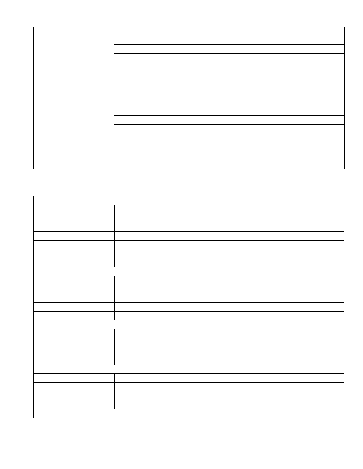
SPECIFICATION
TH-G40
General
Power supply Refer to main label.
Power consumption Refer to main label.
Net Weight 4 kg
External dimensions (W x H x D) 430 x 72 x 307 mm
Operating conditions Temperature: 5°C to 35°C Operation status: Horizontal
Operating humidity 5% to 85%
Laser Semiconductor laser, wavelength 650 nm
CD/DVD
Video system NTSC
Frequency response (audio) 140 Hz to 20 kHz *
Signal-to-noise ratio (audio) More than 75 dB (1 kHz 20 kHz LPF/A-Filter) *
Dynamic range (audio) More than 75 dB *
Harmonic distortion (audio) 0.5 % (1 kHz at 1W position) (20 kHz LPF) *
Video
Video output 1.0 V (p-p) 75 Ω negative sync. RCA jack x 1
COMPONENT VIDEO OUT (Y) 1.0 V (p-p) 75 ohms negative sync RCA jack x 1
(PB)/(PR) 0.7 V (p-p) 75 ohms RCA jack x 1
HDMI OUT 480p/720p/1080i/1080p
Tuner (FM)
Tuning Range 87.5 - 108.0 MHz
Intermediate Frequency 10.7 MHz
Signal-to Noise Ratio 60 dB (Mono) *
Frequency Response 140 - 10,000 Hz *
Amplifier
Stereo mode 155 W + 155 W (4Ω at 1 kHz, THD 10 %)
Surround mode
(* Depending on the sound mode settings
and the source there may be no sound output.)
Inputs AUDIO IN, OPTICAL IN, AUX IN
Outputs MONITOR OUT HDMI OUT COMPONENT VIDEO OUT
Front/Rear Speaker Type 1 Way 1 Speaker
Impedance 4 Ω
Frequency Response 120 - 20000 Hz
Sound Pressure Level 83 dB/W (1m)
Rated Input Power 155 W
Max. Input Power 310 W
Net Dimensions (W x H x D) 117 x 210 x 111 mm
Net Weight 0.9 kg
Front: 155 W + 155 W (THD 10 %)
center*: 155 W
Surround*: 155 W + 155 W (4Ω at 1 kHz THD 10 %)
Subwoofer*: 225 W (3Ω at 70 Hz THD 10 %)
Speakers
1-2 (No.MB672<Rev.002>)
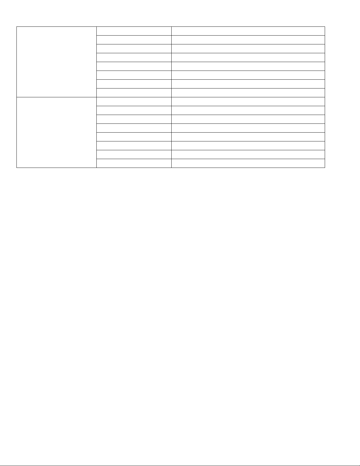
Page 3
center speaker Type 1 Way 1 Speaker
Impedance 4 Ω
Frequency Response 120 -20000 Hz
Sound Pressure Level 83 dB/W (1m)
Rated Input Power 155 W
Max. Input Power 310 W
Net Dimensions (W x H x D) 300 x 115 x 111 mm
Net Weight 1.1 kg
Passive Subwoofer Type 1 Way 1 Speaker
Impedance 3 Ω
Frequency Response 40 - 1500 Hz
Sound Pressure Level 82 dB/W (1m)
Rated Input Power 225 W
Max. Input Power 450 W
Net Dimensions (W x H x D) 236 x 435 x 391 mm
Net Weight 5.7 kg
Items with * are measured at Front Speaker Terminals in STEREO mode
Designs and specifications are subject to change without notice.
TH-G40UJ
General
Power supply 110-240 V ~ 50/60 Hz
Power consumption 130 W
Net Weight 4 kg
External dimensions (W x H x D) 430 x 72 x 307 mm
Operating conditions Temperature: 5°C to 35°C,Operation status: Horizontal
Operating humidity 5% to 85%
Laser Semiconductor laser,wavelength 650 nm
CD/DVD
Video system NTSC
Frequency response (audio) 140 Hz to 20 kHz*
Signal-to-noise ratio (audio) More than 75 dB (1 kHz,20 kHz LPF/A-Filter)*
Dynamic range (audio) More than 75 dB*
Harmonic distortion (audio) 0.5 % (1 kHz,at 1W position) (20 kHz LPF)*
Video
Video output 1.0 V (p-p),75 Ω,negative sync.,RCA jack x 1
COMPONENT VIDEO OUT (Y) 1.0 V (p-p),75 ohms,negative sync,RCA jack x 1
(PB)/(PR) 0.7 V (p-p),75 ohms,RCA jack x 1
HDMI OUT 480p/720p/1080i/1080p
Tuner (FM)
Tuning Range 87.5 - 108.0 MHz
Intermediate Frequency 10.7 MHz
Signal-to Noise Ratio 60 dB (Mono)*
Frequency Response 140 - 10000 Hz*
Amplifier
(No.MB672<Rev.002>)1-3
Page 4

Surround mode
(* Depending on the sound mode
settings and the source
there may be no sound output.)
Inputs AUDIO IN,OPTICAL IN,AUX IN
Outputs MONITOR OUT,HDMI OUT,COMPONENT VIDEO OUT
Front/Rear Speaker Type 1 Way 1 Speaker
center speaker Type 1 Way 1 Speaker
Passive Subwoofer Type 1 Way 1 Speaker
Items with * are measured at Front Speaker Terminals in STEREO mode
Designs and specificat ion s are sub jec t to chan ge witho ut noti ce .
Front: 155 W + 155 W (THD 10 %)
center*: 155 W
Surround*: 155 W + 155 W (4Ω at 1 kHz,THD 10 %)
Subwoofer*: 225 W (3Ω at 70 Hz,THD 10 %)
Speakers
Impedance 4 Ω
Frequency Response 120 - 20000 Hz
Sound Pressure Level 83 dB/W (1m)
Rated Input Power 155 W
Max. Input Power 310 W
Net Dimensi ons (W x H x D) 117 x 210 x 111 mm
Net Weight 0.9 kg
Impedance 4 Ω
Frequency Response 120 -20000 Hz
Sound Pressure Level 83 dB/W (1m)
Rated Input Power 155 W
Max. Input Power 310 W
Net Dimensi ons (W x H x D) 300 x 115 x 111 mm
Net Weight 1.1 kg
Impedance 3 Ω
Frequency Respon se 40 - 1500 Hz
Sound Pressure Level 82 dB/W (1m)
Rated Input Power 225 W
Max. Input Power 450 W
Net Dimensi ons (W x H x D) 236 x 435 x 391 mm
Net Weight 5.7 kg
1-4 (No.MB672<Rev.002>)
Page 5

TH-G30
General
Power supply Refer to main label.
Power consumption Refer to main label.
Net Weight 4 kg
External dimensions (W x H x D) 430 x 72 x 307 mm
Operating conditions Temperature: 5°C to 35°C Operation status: Horizontal
Operating humidity 5% to 85%
Laser Semiconductor laser, wavelen gth 650 nm
CD/DVD
Video system NTSC
Frequency response (audio) 140 Hz to 20 kHz *
Signal-to-noise ratio (audio) More than 75 dB (1 kHz 20 kHz LPF/A-Filter) *
Dynamic range (audio) More than 75 dB *
Harmonic distortion (audio) 0.5 % (1 kHz at 1W position) (20 kHz LPF) *
Video
Video output 1.0 V (p-p) 75 Ω negative sync. RCA jack x 1
COMPONENT VIDEO OUT (Y) 1.0 V (p-p) 75 ohms negative syn c RCA jack x 1
(PB)/(PR) 0.7 V (p-p) 75 ohms RCA jack x 1
HDMI OUT 480p/720p/1080i/1080p
Tuner (FM)
Tuning Range 87.5 - 108.0 MHz
Intermediate Frequency 10.7 MHz
Signal-to Noise Ratio 60 dB (Mono) *
Frequency Response 140 - 10,000 Hz *
Amplifier
Stereo mode 155 W + 155 W (4Ω at 1 kHz, THD 10 %)
Surround mode
(* Depending on the sound mode settings
and the source there may be no sound output.)
Inputs AUDIO IN, OPTICAL IN, AUX IN
Outputs MONITOR OUT HDMI OUT COMPONENT VIDEO OUT
Front/Rear Speaker Type 1 Way 1 Speaker
Impedance 4 Ω
Frequency Response 120 - 20000 Hz
Sound Pressure Level 83 dB/W (1m)
Rated Input Power 155 W
Max. Input Power 310 W
Net Dimensions (W x H x D) 117 x 210 x 111 mm
Net Weight 0.9 kg
Front: 155 W + 155 W (THD 10 %)
center*: 155 W
Surround*: 155 W + 155 W (4Ω at 1 kHz THD 10 %)
Subwoofer*: 225 W (3Ω at 70 Hz THD 10 %)
Speakers
(No.MB672<Rev.002>)1-5
Page 6
center speaker Type 1 Way 1 Speaker
Impedance 4 Ω
Frequency Response 120 -20000 Hz
Sound Pressure Level 83 dB/W (1m)
Rated Input Power 155 W
Max. Input Power 310 W
Net Dimensions (W x H x D) 300 x 115 x 111 mm
Net Weight 1.1 kg
Passive Subwoofer Type 1 Way 1 Speaker
Impedance 3 Ω
Frequency Response 40 - 1500 Hz
Sound Pressure Level 82 dB/W (1m)
Rated Input Power 225 W
Max. Input Power 450 W
Net Dimensions (W x H x D) 236 x 435 x 391 mm
Net Weight 5.7 kg
Items with * are measured at Front Speaker Terminals in STEREO mode
Designs and specificat ion s are sub jec t to chan ge witho ut noti ce .
1-6 (No.MB672<Rev.002>)
Page 7

SECTION 1
PRECAUTION
1.1 Safety Precautions
(1) This design of this product contains special hardware and
many circuits and com ponen ts sp ecial ly for s afety purp oses. For continued protection, no changes should be made
to the original design unless authorized in writing by the
manufacturer. Replacement parts must be identical to
those used in the original circuits. Services should be performed by qualified personnel only.
(2) Alterations of the design or circuitry of the product should
not be made. Any design alterations of the product should
not be made. Any design alterations or additions will void
the manufacturers warranty and will further relieve the
manufacture of respo nsibility for pe rsonal injury or property
damage resulting therefrom.
(3) Many electrical and mechanical parts in the products have
special safety-related characteristics. These characteristics are often not evident from vi sual insp ection nor can the
protection afforded by them nec essaril y be obtained by using replacement compon ents rated for higher voltag e, wattage, etc. Replacement parts which have these special
safety characteristic s ar e identified in the Parts L is t of Service Manual. Electrical components having such features
are identified by shading on the schemat ics and by ( ) on
the Parts List in the Servic e Manual. The use o f a substitute
replacement which does not have the s am e safety characteristics as the recommended replacement parts shown in
the Parts List of Service Manual may create shock, fire, or
other hazards.
(4) The leads in the products are routed and dressed w ith ties,
clamps, tubings, barrie r s a nd th e li ke to be separated from
live parts, high temperature parts, moving parts and/or
sharp edges for the prevention of electric shock and fire
hazard. When service is required, the original lead routing
and dress should be observed, and it should be confirmed
that they have been returned to normal, after reassembling.
(5) Leakage shock hazard testing
After reass embling the produc t, always perform an is olation check on the exposed metal parts of the product (antenna terminals, knobs, metal cabinet, screw heads,
headphone jack, con trol shaft s, etc.) to be sure th e product
is safe to operate without danger of elect rical shock. Do not
use a line isolation transformer during this check.
• Plug the AC line cord directly into the AC outlet. Using a
"Leakage Current Test er", measure the leak age cu rrent
from each exposed metal parts of the cabinet, parti cularly any exposed metal part having a return path to the
chassis, to a kn own good earth g round. Any lea kage current must not exceed 0.5mA AC (r.m.s.).
• Alternate check method
Plug the AC line cord directly into the AC outlet. Use an
AC voltmeter having, 1,000Ω per volt or more sensitivity
in the following mann er. C on nec t a 1 ,500Ω 10W resistor
paralleled by a 0.15µF AC-type capacitor between an exposed metal part and a known good earth ground.
Measure the AC voltage across the resistor with the AC
voltmeter.
Move the resistor connection to each exposed metal
part, particularly any exposed metal part having a return
path to the chassis, and measu re t he AC volt age acros s
the resis tor. Now, r ever se th e plug in th e AC o utlet and
repeat each measurement. Voltage measured any must
not exceed 0.75 V AC (r.m.s.). This corresponds to 0.5
mA AC (r.m.s.).
AC VOLTMETER
(Having 1000
ohms/volts,
or more sensitivity)
0.15 F AC TYPE
Place this
probe on
1500 10W
Good earth ground
1.2 Warning
(1) This equipment has been designed and manufactured to
meet international safety standards.
(2) It is the legal responsibility of the repairer to ensure that
these safety standards are maintained.
(3) Repairs must be made in accordance with the relevant
safety standards.
(4) It is essential that safety critical components are replaced
by approved parts.
(5) If mains voltage selector is provid ed, check setting for local
voltage.
1.3 Caution Burrs formed during molding may be left over on some parts
of the chassis.
Therefore, pay attention to such burrs in the case of preforming repair of this system.
1.4 Critical parts for safety
In regard with component parts appearing on the silk-screen
printed side (parts side) of the PWB dia gra ms , the pa rts that are
printed over with black such as the resistor ( ), diode ( )
and ICP ( ) or identified by the " " mark nearby are critical
for safety. When replacing them, be sure to use the parts of the
same type and rating as specified by the manufacturer.
(This regulation dose not Except the J and C version)
each exposed
metal part.
(No.MB672<Rev.002>)1-7
Page 8

1.5 Preventing static electricity
Electrostatic disc ha rge (ESD ), wh ic h oc cu rs w he n st ati c el ec tric ity sto red in the body, fabric, e tc. is d is cha rge d, ca n de stroy the laser
diode in the traverse unit (optical pickup). Take care to prevent this when performing repairs.
1.5.1 Grounding to prevent damage by static electricity
Static electricity in the work area can destroy the optical pickup (laser diode) in devices such as laser products.
Be careful to use proper grounding in the area where repairs are being performed.
(1) Ground the workbench
Ground the workbench by laying conductive material (such as a conductive sheet) or an iron plate over it before placing the
traverse unit (optical pickup) on it.
(2) Ground yourself
Use an anti-static wrist strap to release any static electricity built up in your body.
(caption)
Anti-static wrist strap
1M
Conductive material
(conductive sheet) or iron palate
(3) Handling the optical pickup
• In order to maintain quality during transport and before installation, both sides of the laser diode on the replacement optical
pickup are shorted. After replacement, return the shorted parts to their original condition.
(Refer to the text.)
• Do not use a tester to ch eck the co ndition of th e laser dio de in the op tical pickup . The tester' s interna l power sourc e can easily
destroy th e laser diode.
1.6 Handling the traverse unit (optical pickup)
(1) Do not subject the traverse unit (optical pickup) to strong shocks, as it is a sensitive, complex unit.
(2) Cut off the shorted part of the flexible cable using nip pers, etc . after replac ing the optic al pickup. For sp ecific det ails, refer to the
replacement procedu re i n the text. Remove the an ti-s tatic pin when repl aci ng the traverse unit. Be careful not to take t oo lon g a
time when attaching it to the connector.
(3) Handle the flexible cable carefully as it may break when subjected to strong force.
(4) I t is not possible to adjust the semi-fixed resistor that adjusts the laser power. Do not turn it.
1.7 Attention when traverse unit is decomposed *Please refer to "Disassembly method" in the text for the pickup unit.
• Apply solder to the short lan d se cti ons befo re the card wi re is di sc on nec ted from the con ne cto on the s erv o boa rd. (If the card wire
is disconnected without applying solder, the pickup may be destroyed by static electricity.)
• In the assembly, be sure to remove solder from the short land sections after connecting the card wire.
Solder short land section
1-8 (No.MB672<Rev.002>)
Page 9

1.8 Important for laser products
1.CLASS 1 LASER PRODUCT
2.CAUTION :
(For U.S.A.) Visible and/or invisible class II laser radiation
when open. Do not stare into beam.
(Others) Visible and/or invisible class 1M laser radiation
when open. Do not view directly with optical instruments.
3.CAUTION : Visible and/or invisible laser radiation when
open and inter lock failed or defeated. Avoid direct
exposure to beam.
4.CAUTION : This laser product uses visible and/or invisible
laser radiation and is equipped with safety switches which
prevent emission of radiation when the drawer is open and
the safety interlocks have failed or are defeated. It is
dangerous to defeat the safety switches.
5.CAUTION : If safety switches malfunction, the laser is able
to function.
6.CAUTION : Use of controls, adjustments or performance of
procedures other than those specified here in may result in
hazardous radiation exposure.
!
Please use enough caution not to
see the beam directly or touch it
in case of an adjustment or operation
check.
(No.MB672<Rev.002>)1-9
Page 10

1.9 Importance admistering point on the safety
slow blow type / type a fusion lent
Full Fuse Replacement Marking
Graphic symbol mark
(This symbol means slow blow type fuse.)
should be read as follows ;
FUSE CAUTION
FOR CONTINUED PROTECTION AGAINST RISK
OF FIRE, REPLACE ONLY WITH SAME TYPE
AND RATING OF FUSES ;
F901 : T12AH 250V F901 : T12AH 250V
SECTION 2
SPECIFIC SERVICE INSTRUCTIONS
Marquage Pour Le Remplacement
Complet De Fusible
Le symbole graphique (Ce symbole signifie
fusible de type a fusion lent.)
^
doit etre interprete comme suit ;
PRECAUTIONS SUR LES FUSIBLES
POUR UNE PROTECTION CONTINUE CONTRE
DES RISQUES D'INCENDIE, REMPLACER
SEULEMENT PAR UN FUSIBLE DU MEME TYPE ;
This service manual does not describe SPECIFIC SERVICE INSTRUCTIONS.
1-10 (No.MB672<Rev.002>)
Page 11

SECTION 3
DISASSEMBLY
3.1 Main body
3.1.1 Removing the Metal cover (See Fig. 1, 2)
(1) Remove the three screws A attaching the Metal cover.
(See Fig.1)
(2) Remove the four screws B attaching the both side of the
Metal cover. (See Fig.2)
3.1.2 Removing the Front Panel (See Fig. 3 to 6)
(1) Disconnect the card wire from Front panel connected to
connector PN103
(2) From the top side of the Front panel, disengage three
hooks a engaged Front panel. (See Fig.4)
(3) From the both side of the Front panel, disengage two
hooks b engaged Front panel. (See Fig.5)
(4) From the bottom side of the Front panel, disengage three
hooks c engaged Front panel. (See Fig.6)
of the Amp board. (See Fig.3)
A
Fig.1
Fig.2
hook
Fig.4
B
a
Fig.3
hook b
Fig.5
PN103
hook c
Fig.6
(No.MB672<Rev.002>)1-11
Page 12

3.1.3 Removing the HDMI board (See Fig. 7, 8)
(1) Remove the one screw C attaching t h e HDMI board. ( Se e
Fig.7)
(2) Disconnect the card wire from Main board connected to
connector CN810
(3) Remove the three screws D attaching the HDMI board.
(See Fig.8)
of the HDMI board. (See Fig.8)
C
Fig.7
D
3.1.4 Removing the DVD mechanism (See Fig.9)
(1) Disconnect the card wires from DVD mechanism connect-
ed to connector P400
(2) Remove the four screws E attaching the DVD mechanism.
and P401 of the Main board.
CN810
Fig.8
EE
P400P401
Fig.9
1-12 (No.MB672<Rev.002>)
Page 13

3.1.5 Removing the Rear panel (See Fig.10, 11)
(1) Disconnect the Power cord from connector PN901
SMPS board. (See Fig.10)
(2) Disconnect the connector wir e from FA N connected to con-
nector PN603
(3) Remove the one screw F and seven screws G attaching
the Rear panel. (See Fig.11)
3.1.6 Removing the Front jack board (See Fig.12)
(1) Disconnect the card wire from Front jack board connected
to connector PN204 of the Main board.
(2) Remove the two screws H attaching the Front jack board.
of the Amp board. (See Fig.10)
of the
PN901
PN603
Fig.10
F
G
Fig.11
H
PN204
Fig.12
(No.MB672<Rev.002>)1-13
Page 14

3.1.7 Removing the Main board (See Fig.13, 14)
(1) Remove the two screws J attaching the bracket. (See
Fig.13)
(2) Disconnect the connector wire from Main board connected
to connector CN901
(3) Disconnect the card wires from Amp board connected to
connector PN202 and PN203 of the Main board. (See
Fig.14)
(4) Remove the two screws K attaching t h e M ain bo a r d. ( S ee
Fig.14)
of the SMPS board. (See Fig.14)
J
Fig.13
CN901
K
3.1.8 Removing the SMPS board (See Fig.15)
(1) Disconnect the connector wire from Amp board connected
to connector CN602
(2) Remove the five screws L attaching the SMPS board.
of the SMPS board.
PN202
PN203
Fig.14
L
1-14 (No.MB672<Rev.002>)
CN602
Fig.15
Page 15

3.1.9 Removing the Amp board (See Fig.16)
(1) Remove the four screws M attaching the Amp board.
3.1.10 Removing the Front key board (See Fig.17)
(1) Remove the one screw N attaching the Front key board.
M
Fig.16
N
3.1.11 Removing the FL board (See Fig.18)
(1) Remove the five screws P attaching the FL board.
Fig.17
P
Fig.18
(No.MB672<Rev.002>)1-15
Page 16

3.2 DVD mechanism
3.2.1 Main base (See Fig.1)
(1) Place the disc clamp assembly as Fig.1.
(2) Lift up the disc clamp assembly i n direction of the a rrow (A).
(3) Separate the disc clamp assembly from the Clamp holder.
(4) Turn the Clamper plate to counterclockwise direction and
then lift up the clamper plate.
3.2.2 Disc tray (See Fig.2)
(1) Insert and push a screwdriver in the emergency eject hole
(A) at the right side, or put the screwdriver on the lever (B)
of the emergency gear and pull the lever (B) in direction of
arrow so that the Disc tray is ejected about 15 ~ 20 mm.
(2) Pull the Disc tray until it is separated from the Main base
completely.
Clamper plate
Magnet clamp
Upper clamp
Disc tray
Main base
Disc clamp assembly
(A)
(Fig. A)
Clamp holder
Main base
Fig.1
Main base
Lever
(B)
Main base
BOTTOM SIDE VIEW
Fig.2
1-16 (No.MB672<Rev.002>)
Page 17

3.2.3 Slide base assembly (See Fig.3)
(1) Release the four screws (S2).
(2) Disconnect the FFC connector (C1).
(3) Release the screw (S3).
Rubber damper
Distinguish upper and
lower sides
(Assemble with care)
Rubber damper
(S2)
(S3)
(C1)
Reck gear
Spindle motor assembly
Rubber damper
(S2)
General pickup assembly
Fig.3
(S2)
Pickup base
(S2)
(No.MB672<Rev.002>)1-17
Page 18

3.2.4 Up/Down frame assembly (See Fig.4)
NOTE:
Put the Main base face down (Bottom side)
(1) Release the screw (S4).
(2) Unlock the Locking tab (L3) in direction of arro w and then lift u p the Up/down f rame assembly t o separate it fro m the Main base.
NOTE:
When reassembling move the Up/Down guide in direction of arrow (C) until it is positioned as Fig (C).
When reassembling insert (A) position of the Up/down frame assembl y in the (B) position of the Up/down frame as sembly as Fig (B).
3.2.5 Pulley gear (See Fig.4)
(1) Unlock the locking tab (L4) in direction of arrow (B) and then separate the pulley gear from the main base.
3.2.6 Up/down guide (See Fig.4)
(1) Move the Up/down guide in direction of arrow (A) as Fig (A).
(2) Push the locking tab (L5) down and then lift up the Up/down guide to separate it from the main base.
NOTE:
When reassembling pla ce the Up/ down guide as Fig (C) and m ove it directio n arrow (B) unti l it is lock ed by the lock ing tab (L5). And
confirm the Up/down guide as Fig (A).
3.2.7 Loading board assembly (See Fig.4)
(1) Release one screw (S5).
(2) Unlock the loading motor (C2) from the hook (H1) on the main base.
(3) Unlock two locking tabs (L6) and separate the loading board assembly from the main base.
Up/Down guide
Loading gear
Screw insertion
torque control
Up/Down guide
Pully gear
Loading belt
(A)
(L5)
FIG. (A)
(L4)
Loading board assembly
Main base
(A)
(B)
(C)
(B)
Up/Down guide
FIG. (C)
Fig.4
(S5)
(L3)
(H1)
(C2)
(A)
(B)
FIG. (B)
Up/Down guide
(L6)
(L6)
Main base
(S4)
(S4)
Up/Down frame assembly
1-18 (No.MB672<Rev.002>)
Page 19

SECTION 4
ADJUSTMENT
This service manual does not describe ADJUSTMENT.
(No.MB672<Rev.002>)1-19
Page 20

5.1 Power Supply Circuit
Insert power cord.
SECTION 5
TROUBLESHOOTING
YES
Is the Digitron on correctly?
YES
Turn power on.
YES
Is power on?
YES
Does initial read work?
YES
NO
NO
NO
Check power plug and power
supply circuit.
Check power supply circuit.
Check laser circuit.
Check focus circuit.
Check disc.
Does it play?
Does it output
1-20 (No.MB672<Rev.002>)
audio?
OK
NO
Check tracking servo circuit.
YES
NO
Check audio circuit.
YES
Page 21

5.2 Front circuit
Power on.
YES
Blue LED turn off?
YES
Is the Digitron on
correctly?
YES
Check if all
buttons are ok?
YES
NO
NO
NO
Check if
PN301 is ok?
YES
Check if the front
power is ok?
YES
Check if
DIS301 is ok?
Check if the
power part of the
front is ok?
YES
Check if
R345~R350, R154
ok?
YES
NO
Reconnect it.
NO
Refer to SMPS part.
NO
Check pattern and resoldering
NO
Refer to power(SMPS).
NO
Check if the remote
control is ok?
YES
Front B/D ok.
Refer to MICOM circuit.
NO
Check if the power
part of the front is ok?
Check if the remote
control waveform of PN301
pin11 is ok?
Check if RC2
voltage is ok(5V)?
Resolder or Replace RC2.
Replace R345 ~ R350, R154.
NO
Refer to power(SMPS).
YES
NO
Refer to MICOM circuit.
YES
NO
Check RM circuit
YES
(No.MB672<Rev.002>)1-21
Page 22

5.3 System operation flow
Power on.
1. Initializes SERVO, DSP & RISC registers.
2. Write RISC code to SDRAM.
3. Reset RISC.
Show LOGO.
YES
Tray closed?
NO
Tray close to closed position.
YES
SLED at inner side?
NO
SLED moves to inner position.
1. Judge whether have disc and disc type.
2. Jump to related disc reading procedure.
Recieve
OPEN/ CLOSE
Key?
NO
1-22 (No.MB672<Rev.002>)
NO
1. Execute Pressed Key & IR Key.
2. System operation routine loop.
1. Stop Playback & Open Tray.
2. Display tray open message & LOGO.
YES
Receive
CLOSE Key?
YES
Page 23

5.4 AMP Protection
"PROTECTION" appears on the FLD.
After unplug power cord, connect again.
YES
YES
Power on.
YES
"PROTECTION"
appears continuously on the FLD.
YES
Is the IC101 pin54
"LOW" signal(0V)?
YES
Is the Q703, Q704 and Q705 normal?
YES
Replace TI AMP IC(IC701, IC702, IC703, IC704)
NO
OK.
NO
Replace IC101.
NO
Replace the Q703, Q704 and Q705.
(No.MB672<Rev.002>)1-23
Page 24

5.5 AUDIO Micom Circuit (DVD & AMP)
Power On.
YES
Does
CD/DVD appear at
FLD?
YES
Does
Loading appear
at FLD?
YES
Does
no Disc or Time
appear at FLD?
YES
Check
if DVD an audio
micom insert is
OK.
YES
NO
NO
Does
it appear DVD Error
at FLD?
YES
Check
power part of Main
B/D.
YES
Check
oscillator
X101.
YES
Does AV1,
TV AUDIO, AV1 OPT and
FM 87.5 appear
at FLD.
NO
NO
NO
Refer to SMPS.
NO
Refer to oscillator cir-
cuit.
YESNO
OK
Check Power.
YES
Check DVD Module.
YES
Check SMPS.
NO
Check
if IC101 Pin5
is high.
YES
Check
if IC101 Pin9,36,59 are
high(5V).
YES
Check
if IC101 Pin44
is high.
YES
Replace IC101.
NO
Check IC101 reset
waveform.
NO
Check 5V line.
NO
Check power section
circuit.
1-24 (No.MB672<Rev.002>)
Page 25

5.6 DETAILS AND WAVEFORMS ON SYSTEM TEST AND DEBUGGING
5.6.1 SYSTEM 27MHz CLOCK,RESET,FLASH R/W SIGNAL
1) ES8391 main clock is at 27MHz(X501)
1
2) ES8391 reset is high active.
1
IC101
PWR_CTL
DVD_RESET
MRST#
1
2
3
2 1
IC501
3
(No.MB672<Rev.002>)1-25
Page 26

5.6.2 SDRAM CLOCK
1) ES8391 main clock is at 27MHz(X501)
DCLK = 93MHz, Vp-p=2.2, Vmax=2.7V
1
5.6.3 TRAY OPEN/CLOSE SIGNAL
1) Tray open/close waveform 2) Tray close waveform
1
OPENSW
CLOSESW
CLOSE
3) Tray open waveform
OPEN
OPENSW
CLOSESW
OPEN
CLOSE
1
OPENSW
1
CLOSESW
2
2
3
4
OPEN
CLOSE
3
4
1
1
2
2
3
1-26 (No.MB672<Rev.002>)
4
4
3
Page 27

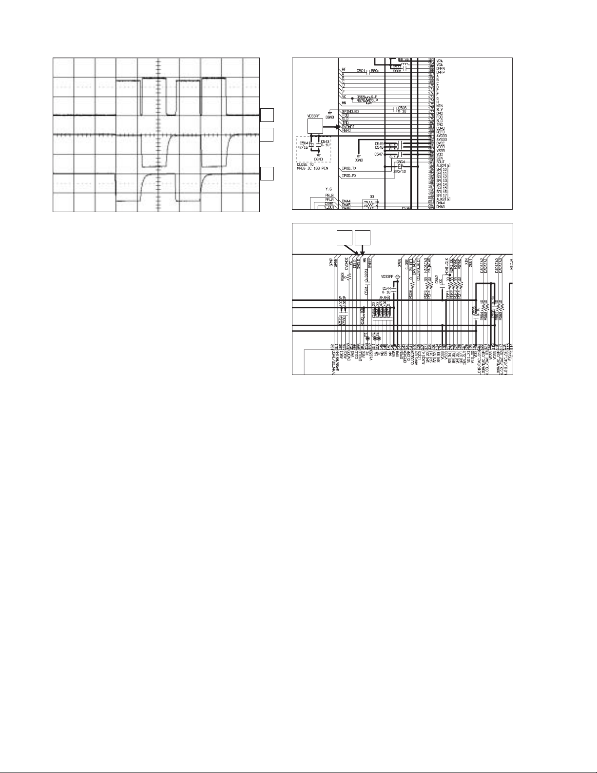
5.6.4 SLED CONTROL RELATED SIGNAL (NO DISC CONDITION)
1
2
3
4
1
2
5.6.5 LENS CONTROL RELATED SIGNAL(NO DISC CONDITION)
1
2
3
3
4
1
IC501
2
3
(No.MB672<Rev.002>)1-27
Page 28
5.6.6 LASER POWER CONTROL RELATED SIGNAL(NO DISC CONDITION)
1
2
1
IC501
3
23
1-28 (No.MB672<Rev.002>)
Page 29

5.6.7 DISC TYPE JUDGEMENT WAVEFORMS
F+
CD_DVDCT
1
2
F+
CD_DVDCT
3
RF
RF
(DVD)
F+ F+
1
CD_DVDCT
2
CD_DVDCT
1
2
3
(DVD)
1
2
RF
1
(CD)
3
RF
3
(CD)
2
3
IC501
(No.MB672<Rev.002>)1-29
Page 30

5.6.8 FOCUS ON WAVEFORM S
CD_DVDCT
1
1
FOO
F+
F-
(DVD)
CD_DVDCT
FOO
F+
F-
(DVD)
5.6.9 SPINDLE CONTROL WAVEFORMS (NO DISC CONDITION)
2
3
4
1
2
3
4
2
3
4
IC501
SPINO
SP-
SP+
2
3
1
2
3
1
IC501
1-30 (No.MB672<Rev.002>)
Page 31

5.6.10 TRACKING CONTROL RELATED SIGNAL(System checking)
CD_DVDCT
TRO
TR-
(DVD)
CD_DVDCT
TRO
TR-
TR+
1
1
2
3
4
IC501
1
2
IC501
2
3
TR+
4
(CD)
4
3
(No.MB672<Rev.002>)1-31
Page 32

5.6.11 ES8391 VIDEO OUTPUT WAVEFORMS
1) Full colorbar signal(COMPOSIT)
2) Y
1
1
IC501
5.6.12 AUDIO OUTPUT FROM PWM IC
1) Audio related Signal
1
1
1
IC501
IC501
1-32 (No.MB672<Rev.002>)
2
3
Page 33

5.6.13 DVD & AMP WAVEFORMS
1)
2)
FL+ : TP611 -> R705
FL- : TP612 -> R710
3)
RL+ : TP603 -> R775
RL- : TP604 -> R780
5)
FR+ : TP609 -> R718
FR- : TP610 -> R722
4)
RR+ : TP601 -> R788
RR- : TP602 -> R792
6)
C+ : TP605 -> R731
C- : TP606 -> R736
W+ : TP607 -> R767
W- : TP608 -> R762
4
3
5
6
2
1
(No.MB672<Rev.002>)1-33
Page 34

Victor Company of Japan, Limited
Audio/Video Systems category 10-1,1chome,Ohwatari-machi,Maebashi-city,371-8543,Japan
(No.MB672<Rev.002>)
Printed in Japan
VPT
 Loading...