

Page 1
REVISION INFORMATION
DVD DIGITAL CINEMA SYSTEM
TH-G31A, TH-G31B, TH-G31E, TH-G31EN,
TH-G31UG, TH-G31UH, TH-G31UN, TH-G31UX,
TH-G41A, TH-G41UX, TH-G61A, TH-G61E,
TH-G61EN, TH-G61UH, TH-G61UN, TH-G61UX
■ OVERVIEW
Add TH-G31UG.
■ DETAILS
COVER SECTION
Title Line No.MB713<Rev.002> No.MB713<Rev.003> Description
Revision Rev.002 Rev.003
Issue Date 2010/01 2010/06
Model No. TH-G31A, TH-G31B, TH-G31E, TH-G31EN,
TH-G31UH, TH-G31UN, TH-G31UX, TH-G41A,
TH-G41UX, TH-G61A, TH-G61E, TH-G61EN,
TH-G61UH, TH-G61UN, TH-G61UX
STANDARD SCHEMATIC DIAGRAMS
Schematic Diagram
Diagram Name No.MB713<Rev.002> No.MB713<Rev.003> Description
Menu FRONT JACK CIRCUIT DAIAGRAM FRONT JACK CIRCUIT DIAGRAM
Exploded View
Diagram Name No.MB713<Rev.002> No.MB713<Rev.003> Description
Menu Packing materials and accessories(TH-G41/G31) Packing materials and accessories(TH-G31/G41)
TH-G31A, TH-G31B, TH-G31E, TH-G31EN,
TH-G31UG, TH-G31UH, TH-G31UN, TH-G31UX,
TH-G41A, TH-G41UX, TH-G61A, TH-G61E,
TH-G61EN, TH-G61UH, TH-G61UN, TH-G61UX
COPYRIGHT © 2010 Victor Company of Japan, Limited
MB713-R003
2010/06
Page 2
PARTS LIST
!
!
MODEL No. LIST
Model No. No.MB713<Rev.003>
TH-G31A 01
TH-G31B 02
TH-G31E 03
TH-G31EN 04
TH-G31UG 05
TH-G31UH 06
General assembly [M1MM]
Symbol or
!
M1MM 9 LG-5900R-D004K LG-5900R-D004G FAN 1 01,02,03,04,05,06,07,08,09,0A,
M1MM 9 or LG-5900R-D004G LG-5900R-D004K FAN 1 01,02,03,04,05,06,07,08,09,0A,
M1MM 33 ------------ LG-EBR63693207 MAIN BOARD ASSY (Addition) 1 0F
M1MM 33 ------------ LG-EBR63693228 MAIN BOARD ASSY (Addition) 1 10
<Rev.002> <Rev.003>
Part No.
Electrical parts list Main board [01]
Symbol or
01 IC104 ------------ LG-0IPMGKE022B IC (Addition) 1 01,02,03,04,05,06,07,08,09,0A,0B,
01 IC104 LG-0IPMGKE022B ------------ IC (Deletion) 1 0B,10,0F,09,0A,01,08,07,0E,06
01 IC104 LG-EAN60658301 ------------ IC (Deletion) 1 0C,0D,02,03,04
01 IC104 or LG-0IPMGKE022B LG-EAN60658301 IC 1 02,03,04,0C,0D
01 IC106 ------------ LG-0IPMGKE047A IC (Addition) 1 01,02,03,04,05,06,07,08,09,0A,0B,
01 IC106 LG-0IPMGKE047A ------------ IC (Deletion) 1 0B,10,0F,09,0A,01,08,07,0E,06
01 IC106 LG-EAN42369201 ------------ IC (Deletion) 1 0C,0D,02,03,04
01 IC106 or LG-0IPMGKE047A LG-EAN42369201 IC 1 02,03,04,0C,0D
01 Q403 LG-0TRAU80008A KTA1504/G/-X BIPOLAR TR 1 01,02,03,04,05,06,07,08,09,0A,0B,
01 Q403 or KTA1504/G/-X LG-0TRAU80008A BIPOLAR TR 1 01,02,03,04,05,06,07,08,09,0A,0B,
01 Q405 LG-0TRAU80008A KTA1504/G/-X BIPOLAR TR 1 01,02,03,04,05,06,07,08,09,0A,0B,
01 Q405 or KTA1504/G/-X LG-0TRAU80008A BIPOLAR TR 1 01,02,03,04,05,06,07,08,09,0A,0B,
<Rev.002> <Rev.003>
Part No.
Model No. No.MB713<Rev.003>
TH-G31UN 07
TH-G31UX 08
TH-G41A 09
TH-G41UX 0A
TH-G61A 0B
TH-G61E 0C
Part Name Description Qty Models
Part Name Description Qty Models
Model No. No.MB713<Rev.003>
TH-G61EN 0D
TH-G61UH 0E
TH-G61UN 0F
TH-G61UX 10
0B,0C,0D,0E,0F,10
0B,0C,0D,0E,0F,10
0C,0D,0E,0F,10
0C,0D,0E,0F,10
0C,0D,0E,0F,10
0C,0D,0E,0F,10
0C,0D,0E,0F,10
0C,0D,0E,0F,10
PTB board [03]
Symbol or
03 C2D6 ------------ LG-0CH1104H946 C CAPACITOR (Addition) 1 01,02,03,04,05,06,07,08,09,0A,0B,
03 C2D6 LG-0CH1104H946 ------------ C CAPACITOR (Deletion) 1 0C,0D,0B,10,0F,09,0A,02,03,04,01,
03 C2D6 LG-0RH0000D622 ------------ CHIP RESISTOR (Deletion) 1 0E,06
03 C2D6 or LG-0CH1104H946 LG-0RH0000D622 CHIP RESISTOR 1 05,06,0E
<Rev.002> <Rev.003>
Part No.
Part Name Description Qty Models
0C,0D,0E,0F,10
08,07
Packing and accessories G61 [M3MM]
Symbol or
!
M3MM A19 LG-EAA56672101 LG-5010R-L004C AM ANTENNA 1 0B,0E,0F,10
M3MM A19 or LG-5010R-L004C LG-EAA56672101 AM ANTENNA 1 0B,0E,0F,10
<Rev.002> <Rev.003>
Part No.
Part Name Description Qty Models
Packing and accessories G31/G41 [M4MM]
Symbol or
!
M4MM A1 ------------ LG-AFN73972701 INST ASSY (Addition) 1 05
M4MM A19 LG-EAA56672101 LG-5010R-L004C AM ANTENNA 1 01,05,06,07,08,09,0A
M4MM A19 or LG-5010R-L004C LG-EAA56672101 AM ANTENNA 1 01,05,06,07,08,09,0A
<Rev.002> <Rev.003>
2 (MB713-R003)
Part No.
Part Name Description Qty Models
Page 3

(MB713-R003) 3
Page 4

Victor Company of Japan, Limited
Home Entertainment Business Division Personal AV Operation 10-1,1chome,Ohwatari-machi,Maebashi-city,371-8543,Japan
(MB713-R003)
Printed in Japan
No.MB713<Rev.002> VSE
Page 5
REVISION INFORMATION
DVD DIGITAL THEATER SYSTEM
TH-G51J, TH-G41J, TH-G41C,
TH-G31J, TH-G31C, TH-G61C
■ OVERVIEW
Add TH-G61C.
■ DETAILS
COVER SECTION
Title Line No.MB712<Rev.001> No.MB712<Rev.002> Description
Revision Rev.001 Rev.002
Issue Date 2009/09 2010/02
Model No. TH-G31C, TH-G31J, TH-G41C,
TH-G41J, H-G51J
Cover Illustration ILLUSTRATION(mb712_0001.png) ILLUSTRATION(mb712_0001.png)
Category Audio/Video Systems Division Home Entertainment Business Division Personal
Copyright COPYRIGHT (C) 2009 Victor Company of Japan,
Limited
SPECIFICATION 192 - TH-G61
193 -
194 -
195 -
196 -
197 -
198 -
TH-G31C, TH-G31J, TH-G41C,
TH-G41J, TH-G51J, TH-G61C
AV Operation
COPYRIGHT (C) 2010 Victor Company of Japan,
Limited
General
Power supply
120 V ~ 60 Hz
Power consumption
130 W
Net Weight
3.6 kg
External dimensions (W × H × D)
430 × 76 × 317 mm
Operating conditions
Temperature: 5°C to 35°C, Operation status:
Horizontal
COPYRIGHT © 2010 Victor Company of Japan, Limited
MB712-R002
2010/02
Page 6
Title Line No.MB712<Rev.001> No.MB712<Rev.002> Description
199 -
200 -
201 -
202 -
203 -
204 -
205 -
206 -
207 -
208 -
209 -
210 -
211 -
212 -
213 -
214 -
215 -
216 -
217 -
218 -
219 -
220 -
221 -
222 -
223 -
Operating humidity
5% to 85%
Laser
Semiconductor laser, wavelength 650 nm
CD/DVD
Video system
NTSC
Frequency response (audio)
140 Hz to 20 kHz *
Signal-to-noise ratio (audio)
More than 75 dB (1 kHz, 20 kHz LPF/A-Filter) *
Dynamic range (audio)
More than 75 dB *
Harmonic distortion (audio)
0.5 % (1 kHz, at 1W position) (20 kHz LPF) *
Video
Video output
1.0 V (p-p), 75 Ω, negative sync., RCA jack ×
1
COMPONENT VIDEO OUT
(Y) 1.0 V (p-p), 75 ohms, negative sync, RCA
jack × 1
(PB)/(PR) 0.7 V (p-p), 75 ohms, RCA jack × 1
HDMI OUT
480i/480p/720p/1080i/1080p
Tuner
FM
Tuning Range
87.5 - 108.0 MHz
Intermediate Frequency
10.7 MHz
Signal-to Noise Ratio
60 dB (Mono) *
Frequency Response
140 - 10,000 Hz *
Amplifier
Stereo mode
155 W + 155 W (4Ω at 1 kHz, THD 10 %)
Surround mode(* Depending on the sound
mode settings and the source, there may be
no sound output.)
Front
155 W + 155 W (THD 10 %)
center*
155 W
Surround*
155 W + 155 W (4Ω at 1 kHz, THD 10 %)
Subwoofer*
225 W (3Ω at 70 Hz, THD 10 %)
Inputs
AUDIO IN, OPTICAL IN, AUX IN, iPod
2 (MB712-R002)
Page 7
Title Line No.MB712<Rev.001> No.MB712<Rev.002> Description
224 -
225 -
226 -
227 -
228 -
229 -
230 -
231 -
232 -
233 -
234 -
235 -
236 -
237 -
238 -
239 -
240 -
241 -
242 -
243 -
244 -
245 -
246 -
247 -
Outputs
MONITOR OUT, HDMI OUT, COMPONENT
VIDEO OUT
Speakers
Front Speaker
Type
2 Way 3 Speaker
Impedance
4 Ω
Frequency Response
80 - 18000 Hz
Sound Pressure Level
83 dB/W (1m)
Rated Input Power
155 W
Max. Input Power
310 W
Net Dimensions (W × H × D)
280 × 1201 × 280 mm
Net Weight
4.4 kg
Center speaker
Type
1 Way 1 Speaker
Impedance
4 Ω
Frequency Response
120 -18000 Hz
Sound Pressure Level
83 dB/W (1m)
Rated Input Power
155 W
Max. Input Power
310 W
Net Dimensions (W × H × D)
301 × 118 × 83 mm
Net Weight
0.9 kg
Rear Speaker
Type
1 Way 1 Speaker
Impedance
4 Ω
Frequency Response
120 -18000 Hz
Sound Pressure Level
83 dB/W (1m)
Rated Input Power
155 W
Max. Input Power
310 W
(MB712-R002) 3
Page 8
Title Line No.MB712<Rev.001> No.MB712<Rev.002> Description
248 -
249 -
250 -
251 -
252 -
253 -
254 -
255 -
256 -
257 -
259 - Items with * are measured at Front Speaker
260 - Designs and specifications are subject to change
Net Dimensions (W × H × D)
311 × 209 × 83 mm
Net Weight
0.78 kg
Passive Subwoofer
Type
1 Way 1 Speaker
Impedance
3 Ω
Frequency Response
40 - 1500 Hz
Sound Pressure Level
82 dB/W (1m)
Rated Input Power
225 W
Max. Input Power
450 W
Net Dimensions (W × H × D)
236 × 435 × 391 mm
Net Weight
5.7 kg
Terminals in STEREO mode
without notice.
STANDARD SCHEMATIC DIAGRAMS
Exploded View
Diagram Name No.MB712<Rev.001> No.MB712<Rev.002> Description
Menu Packing materials and accessories Packing materials and accessories 1
Menu - Packing materials and accessories 2
mb712_m401.svgz
PARTS LIST
MODEL No. LIST
Model No.No.MB712<Rev.002>
TH-G31C 05
TH-G31J 04
TH-G41C 03
TH-G41J 02
TH-G51J 01
TH-G61C 06
General assembly [M1MM]
Symbol or
!
M1MM 1 ------------ LG-AGL72919608 FRONT PANEL ASSY (Addition) 1 06
M1MM 2 ------------ LG-ADV72931908 FRAME ASSY (Addition) 1 06
M1MM 12 ------------ LG-3300RCH001B PLATE (Addition) 1 06
M1MM 12 or ------------ LG-3300R-V127A PLATE (Addition) 2 06
! M1MM 16 ------------ LG-MGC58116629 REAR PANEL (Addition) 1 06
<Rev.001> <Rev.002>
Part No.
Part Name Description Qty Models
4 (MB712-R002)
Page 9
Electrical parts list Main board [01]
Symbol or
!
01 C3C6 ------------ LG-0CK104CKG6A C CAPACITOR (Addition) 1 06
01 L3D2 ------------ LG-0LCCE00042A BEAD FILTER (Addition) 1 06
01 L3D3 ------------ LG-0LCCE00042A BEAD FILTER (Addition) 1 06
<Rev.001> <Rev.002>
Part No.
Part Name Description Qty Models
Packing and accessories TH-G61 [M4MM]
Symbol or
!
M4MM A1 ------------ LG-AFN73077614 INST ASSY (Addition) 1 06
M4MM A2 ------------ ------------ BATTERY (Addition) 1 06
M4MM A3 ------------ LG-AKB37006111 REMOCON UNIT (Addition) 1 06
M4MM A4 ------------ LG-6850R-PAA5F RCA CABLE (Addition) 1 06
M4MM A5 ------------ LG-EAD60793901 iPod DOC STATION (Addition) 1 06
M4MM A6 ------------ LG-5010R-T001D FM ANTENA (Addition) 1 06
M4MM A7 ------------ LG-EBR61173101 SPK CORD(L) (Addition) 1 06
M4MM A8 ------------ LG-EBR61173102 SPK CORD(R) (Addition) 1 06
M4MM A9 ------------ LG-EBR61173103 SPK CORD (Addition) 1 06
M4MM A10 ------------ LG-EBR61173104 SPK CORD(W) (Addition) 1 06
M4MM A11 ------------ LG-EBR61173105 SPK CORD(RL) (Addition) 1 06
M4MM A12 ------------ LG-EBR61173106 SPK CORD(RR) (Addition) 1 06
M4MM A13 ------------ LG-EAB60819601 CENTER SPK (Addition) 1 06
M4MM A14 ------------ LG-EAB60799901 FRONT SPK (Addition) 2 06
M4MM A15 ------------ LG-EAB60818401 FRONT SPK STAND (Addition) 2 06
M4MM A16 ------------ LG-EAB60799601 FRONT/REAR SPK (Addition) 2 06
M4MM A17 ------------ LG-EAB51655701 SUBWOOFER (Addition) 1 06
M4MM P1 ------------ LG-MAY62017558 CARTON (Addition) 1 06
M4MM P2 ------------ LG-MFZ47047382 CUSHION (Addition) 1 06
M4MM P3 ------------ LG-MFZ61796853 SPK CUSHION A (Addition) 1 06
M4MM P4 ------------ LG-MFZ61796854 SPK CUSHION B (Addition) 1 06
M4MM P7 ------------ LG-MFZ61796850 SPK CUSHION(BTM) (Addition) 1 06
M4MM P8 ------------ LG-MFZ61796851 SPK CUSHION(MDL) (Addition) 1 06
M4MM P9 ------------ LG-MFZ61796852 SPK CUSHION(TOP) (Addition) 1 06
<Rev.001> <Rev.002>
Part No.
Part Name Description Qty Models
(MB712-R002) 5
Page 10

Victor Company of Japan, Limited
Home Entertainment Business Division Personal AV Operation 10-1,1chome,Ohwatari-machi,Maebashi-city,371-8543,Japan
(MB712-R002)
Printed in Japan
No.MB712<Rev.001> VSE
Page 11
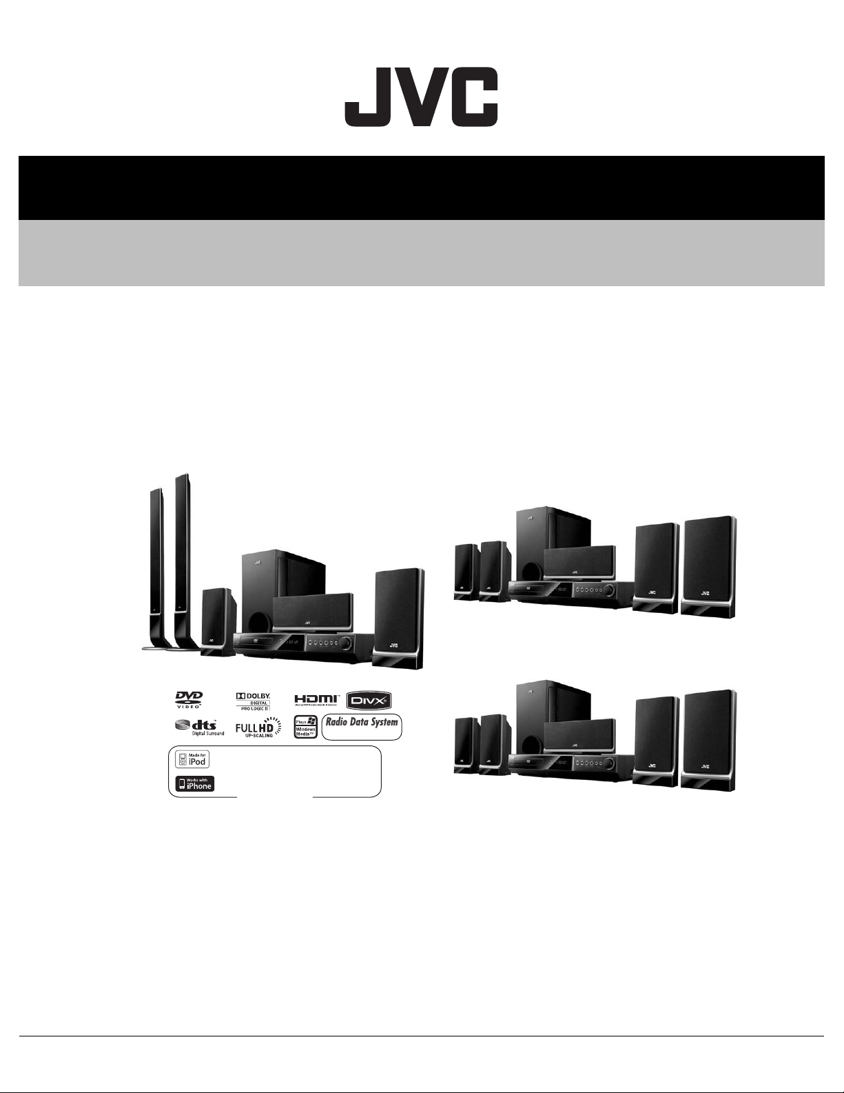
SERVICE MANUAL
DVD DIGITAL CINEMA SYSTEM
MB713<Rev.002>20101SERVICE MANUAL
TH-G61E, TH-G61EN, TH-G61A, TH-G61UX,
TH-G61UN, TH-G41A, TH-G41UX, TH-G31B,
TH-G31E, TH-G31EN, TH-G31A, TH-G31UX,
TH-G31UN, TH-G61UH, TH-G31UH
SP-THG61F
SP-THG50W
SP-THG51F
iPod is a trademark of Apple Inc.,
registered in the U.S. and other countries.
COPYRIGHT © 2010 Victor Company of Japan, LimitedLead free solder used in the board (material : Sn-Ag-Cu, melting point : 219 Centigrade)
XV-THG61
iPhone is a trademark of Apple Inc.
TH-G61A, TH-G41
TH-G61
SP-THG61C
SP-THG51F
Europe only
TH-G31
SP-THG51F
TH-G41
SP-THG51F
SP-THG50W
XV-THG31
SP-THG50W
XV-THG41
SP-THG61C
SP-THG51F
SP-THG61C
SP-THG51F
TABLE OF CONTENTS
1 PRECAUTION. . . . . . . . . . . . . . . . . . . . . . . . . . . . . . . . . . . . . . . . . . . . . . . . . . . . . . . . . . . . . . . . . . . . . . . . 1-14
2 SPECIFIC SERVICE INSTRUCTIONS . . . . . . . . . . . . . . . . . . . . . . . . . . . . . . . . . . . . . . . . . . . . . . . . . . . . . 1-16
3 DISASSEMBLY . . . . . . . . . . . . . . . . . . . . . . . . . . . . . . . . . . . . . . . . . . . . . . . . . . . . . . . . . . . . . . . . . . . . . . 1-17
4 ADJUSTMENT . . . . . . . . . . . . . . . . . . . . . . . . . . . . . . . . . . . . . . . . . . . . . . . . . . . . . . . . . . . . . . . . . . . . . . . 1-20
5 TROUBLESHOOTING . . . . . . . . . . . . . . . . . . . . . . . . . . . . . . . . . . . . . . . . . . . . . . . . . . . . . . . . . . . . . . . . . 1-21
COPYRIGHT © 2010 Victor Company of Japan, Limited
No.MB713<Rev.002>
2010/1
Page 12
SPECIFICATION
EX-A15E/EE
General
Power supply 220 - 240 V ~ 50/60 Hz
Power consumption 130 W
Net Weight 3.6 kg
External dimensions (W × H × D) 430 × 76 × 317 mm
Operating conditions Temperature: 5°C to 35°C, Operation status: Horizontal
Operating humidity 5% to 85%
Laser Semiconductor laser, wavelength 650 nm
CD/DVD
Video system PAL/NTSC
Frequency response (audio) 140 Hz to 20 kHz*
Signal-to-noise ratio (audio) More than 75 dB (1 kHz, 20 kHz LPF/A-Filter)*
Dynamic range (audio) More than 75 dB*
Harmonic distortion (audio) 0.5 % (1 kHz, at 1W position) (20 kHz LPF)*
Video
Video output 1.0 V (p-p), 75 Ω, negative sync., RCA jack × 1/ SCART (TO TV)
COMPONENT VIDEO OUT (Y) 1.0 V (p-p), 75 ohms, negative sync, RCA jack × 1
HDMI OUT 480i (or 576i)/480p (or 576p)/720p/1080i/1080p
Tuner
FM Tuning Range 87.5 - 108.0 MHz
AM (for Australia and Asia) Tuning Range 522 - 1,710 MHz
Amplifier
Stereo mode 155 W + 155 W (4Ω at 1 kHz, THD 10 %)
Surround mode
(* Depending on the sound mode
settings and the source, there
may be no sound output.)
Inputs AUDIO IN, OPTICAL IN, AUX IN, USB, TV-AUDIO (SCART)
Outputs MONITOR OUT, HDMI OUT, SCART (for Europe), COMPONENT VIDEO OUT
Speakers
Front Speaker Type 2 Way 3 Speaker
TH-G61 Europe and Oceania
(PB)/(PR) 0.7 V (p-p), 75 ohms, RCA jack × 1
Intermediate Frequency 128 kHz
Signal-to Noise Ratio 60 dB (Mono) *
Frequency Response 140 - 10,000 Hz *
Intermediate Frequency 128 kHz
Front 155 W
Center* 155 W + 155 W (4Ω at 1 kHz, THD 10 %)
Surround* 225 W (3Ω at 70 Hz, THD 10 %)
Subwoofer*
Impedance 4 Ω
Frequency Response 80 - 18000 Hz
Sound Pressure Level 83 dB/W (1m)
Rated Input Power 155 W
Max. Input Power 310 W
Net Dimensions (W × H × D) 280 × 1201 × 280 mm
Net Weight 4.4 kg
1-2 (No.MB713<Rev.002>)
Page 13
Center speaker Type 1 Way 1 Speaker
Impedance 4 Ω
Frequency Response 120 - 18000 Hz
Sound Pressure Level 83 dB/W (1m)
Rated Input Power 155 W
Max. Input Power 310 W
Net Dimensions (W × H × D) 301 × 118 × 83 mm
Net Weight 0.9 kg
Rear Speaker Type 1 Way 1 Speaker
Impedance 4 Ω
Frequency Response 120 - 18000 Hz
Sound Pressure Level 83 dB/W (1m)
Rated Input Power 155 W
Max. Input Power 310 W
Net Dimensions (W × H × D) 113 × 209 × 83 mm
Net Weight 0.78 kg
Passive Subwoofer Type 1 Way 1 Speaker
Impedance 3 Ω
Frequency Response 40 - 1500 Hz
Sound Pressure Level 82 dB/W (1m)
Rated Input Power 255 W
Max. Input Power 450 W
Net Dimensions (W × H × D) 236 × 435 × 391 mm
Net Weight 5.7 kg
USB
Output power DC 5V 500mA
Items with * are measured at Front Speaker Terminals in STEREO mode
Designs and specifications are subject to change without notice.
(No.MB713<Rev.002>)1-3
Page 14

TH-G61 Asia
General
Power supply 110 - 240 V ~ 50/60 Hz
Power consumption 130 W
Net Weight 3.6 kg
External dimensions (W × H × D) 430 × 76 × 317 mm
Operating conditions Temperature: 5°C to 35°C, Operation status: Horizontal
Operating humidity 5% to 85%
Laser Semiconductor laser, wavelength 650 nm
CD/DVD
Video system PAL/NTSC
Frequency response (audio) 140 Hz to 20 kHz*
Signal-to-noise ratio (audio) More than 75 dB (1 kHz, 20 kHz LPF/A-Filter)*
Dynamic range (audio) More than 75 dB*
Harmonic distortion (audio) 0.5 % (1 kHz, at 1W position) (20 kHz LPF)*
Video
Video output 1.0 V (p-p), 75 Ω, negative sync., RCA jack × 1
COMPONENT VIDEO OUT (Y) 1.0 V (p-p), 75 ohms, negative sync, RCA jack × 1
(PB)/(PR) 0.7 V (p-p), 75 ohms, RCA jack × 1
HDMI OUT 480i (or 576i)/480p (or 576p)/720p/1080i/1080p
Tuner
FM Tuning Range 87.5 - 108.0 MHz
Intermediate Frequency 128 kHz
Signal-to Noise Ratio 60 dB (Mono) *
Frequency Response 140 - 10,000 Hz *
AM (for Australia and Asia) Tuning Range 522 - 1,710 MHz
Intermediate Frequency 128 kHz
Amplifier
Stereo mode 155 W + 155 W (4Ω at 1 kHz, THD 10 %)
Surround mode
(* Depending on the sound mode
settings and the source, there
may be no sound output.)
Inputs AUDIO IN, OPTICAL IN, AUX IN, USB, TV-AUDIO (SCART)
Outputs MONITOR OUT, HDMI OUT, COMPONENT VIDEO OUT
Speakers
Front Speaker Type 2 Way 3 Speaker
Front 155 W
Center* 155 W + 155 W (4Ω at 1 kHz, THD 10 %)
Surround* 225 W (3Ω at 70 Hz, THD 10 %)
Subwoofer*
Impedance 4 Ω
Frequency Response 80 - 18000 Hz
Sound Pressure Level 83 dB/W (1m)
Rated Input Power 155 W
Max. Input Power 310 W
Net Dimensions (W × H × D) 280 × 1201 × 280 mm
Net Weight 4.4 kg
1-4 (No.MB713<Rev.002>)
Page 15

Center speaker Type 1 Way 1 Speaker
Impedance 4 Ω
Frequency Response 120 - 18000 Hz
Sound Pressure Level 83 dB/W (1m)
Rated Input Power 155 W
Max. Input Power 310 W
Net Dimensions (W × H × D) 301 × 118 × 83 mm
Net Weight 0.9 kg
Rear Speaker Type 1 Way 1 Speaker
Impedance 4 Ω
Frequency Response 120 - 18000 Hz
Sound Pressure Level 83 dB/W (1m)
Rated Input Power 155 W
Max. Input Power 310 W
Net Dimensions (W × H × D) 113 × 209 × 83 mm
Net Weight 0.78 kg
Passive Subwoofer Type 1 Way 1 Speaker
Impedance 3 Ω
Frequency Response 40 - 1500 Hz
Sound Pressure Level 82 dB/W (1m)
Rated Input Power 255 W
Max. Input Power 450 W
Net Dimensions (W × H × D) 236 × 435 × 391 mm
Net Weight 5.7 kg
USB
Output power DC 5V 500mA
Items with * are measured at Front Speaker Terminals in STEREO mode
Designs and specifications are subject to change without notice.
(No.MB713<Rev.002>)1-5
Page 16
TH-G41 Oceania
General
Power supply 220 - 240 V ~ 50/60 Hz
Power consumption 130 W
Net Weight 3.6 kg
External dimensions (W × H × D) 430 × 76 × 317 mm
Operating conditions Temperature: 5°C to 35°C, Operation status: Horizontal
Operating humidity 5% to 85%
Laser Semiconductor laser, wavelength 650 nm
CD/DVD
Video system PAL/NTSC
Frequency response (audio) 140 Hz to 20 kHz*
Signal-to-noise ratio (audio) More than 75 dB (1 kHz, 20 kHz LPF/A-Filter)*
Dynamic range (audio) More than 75 dB*
Harmonic distortion (audio) 0.5 % (1 kHz, at 1W position) (20 kHz LPF)*
Video
Video output 1.0 V (p-p), 75 Ω, negative sync., RCA jack × 1
COMPONENT VIDEO OUT (Y) 1.0 V (p-p), 75 ohms, negative sync, RCA jack × 1
(PB)/(PR) 0.7 V (p-p), 75 ohms, RCA jack × 1
HDMI OUT 480i (or 576i)/480p (or 576p)/720p/1080i/1080p
Tuner
FM Tuning Range 87.50 - 108.00 MHz
Intermediate Frequency 128 kHz
Signal-to Noise Ratio 60 dB (Mono) *
Frequency Response 140 - 10,000 Hz *
AM (for Australia and Asia) Tuning Range 522 - 1,710 MHz
Intermediate Frequency 128 kHz
Amplifier
Stereo mode 155 W + 155 W (4Ω at 1 kHz, THD 10 %)
Surround mode
(* Depending on the sound mode
settings and the source, there
may be no sound output.)
Inputs AUDIO IN, OPTICAL IN, AUX IN, iPod, HDMI IN, USB
Outputs MONITOR OUT, HDMI OUT, COMPONENT VIDEO OUT
Speakers
Front/Rear Speaker Type 1 Way 1 Speaker
Front 155 W + 155 W (THD 10 %)
Center* 155 W
Surround* 155 W + 155 W (4Ω at 1 kHz, THD 10 %)
Subwoofer* 225 W (3Ω at 70 Hz, THD 10 %)
Impedance 4 Ω
Frequency Response 120 - 18000 Hz
Sound Pressure Level 83 dB/W (1m)
Rated Input Power 155 W
Max. Input Power 310 W
Net Dimensions (W × H × D) 113 × 209 × 83 mm
Net Weight 0.78 kg
1-6 (No.MB713<Rev.002>)
Page 17

Center speaker Type 1 Way 1 Speaker
Impedance 4 Ω
Frequency Response 120 - 18000 Hz
Sound Pressure Level 83 dB/W (1m)
Rated Input Power 155 W
Max. Input Power 310 W
Net Dimensions (W × H × D) 301 × 118 × 83 mm
Net Weight 0.9 kg
Passive Subwoofer Type 1 Way 1 Speaker
Impedance 3 Ω
Frequency Response 40 - 1500 Hz
Sound Pressure Level 82 dB/W (1m)
Rated Input Power 255 W
Max. Input Power 450 W
Net Dimensions (W × H × D) 236 × 435 × 391 mm
Net Weight 5.7 kg
USB
Output power DC 5V 500mA
Items with * are measured at Front Speaker Terminals in STEREO mode
Designs and specifications are subject to change without notice.
(No.MB713<Rev.002>)1-7
Page 18

TH-G41 Asia
General
Power supply 110 - 240 V ~ 50/60 Hz
Power consumption 130 W
Net Weight 3.6 kg
External dimensions (W × H × D) 430 × 76 × 317 mm
Operating conditions Temperature: 5°C to 35°C, Operation status: Horizontal
Operating humidity 5% to 85%
Laser Semiconductor laser, wavelength 650 nm
CD/DVD
Video system PAL/NTSC
Frequency response (audio) 140 Hz to 20 kHz*
Signal-to-noise ratio (audio) More than 75 dB (1 kHz, 20 kHz LPF/A-Filter)*
Dynamic range (audio) More than 75 dB*
Harmonic distortion (audio) 0.5 % (1 kHz, at 1W position) (20 kHz LPF)*
Video
Video output 1.0 V (p-p), 75 Ω, negative sync., RCA jack × 1
COMPONENT VIDEO OUT (Y) 1.0 V (p-p), 75 ohms, negative sync, RCA jack × 1
(PB)/(PR) 0.7 V (p-p), 75 ohms, RCA jack × 1
HDMI OUT 480i (or 576i)/480p (or 576p)/720p/1080i/1080p
Tuner
FM Tuning Range 87.50 - 108.00 MHz (or 87.5 - 108.0 MHz)
Intermediate Frequency 128 kHz
Signal-to Noise Ratio 60 dB (Mono) *
Frequency Response 140 - 10,000 Hz *
AM (for Australia and Asia) Tuning Range 522 - 1,710 MHz
Intermediate Frequency 128 kHz
Amplifier
Stereo mode 155 W + 155 W (4Ω at 1 kHz, THD 10 %)
Surround mode
(* Depending on the sound mode
settings and the source, there
may be no sound output.)
Inputs AUDIO IN, OPTICAL IN, AUX IN, iPod, HDMI IN, USB
Outputs MONITOR OUT, HDMI OUT, COMPONENT VIDEO OUT
Speakers
Front/Rear Speaker Type 1 Way 1 Speaker
Front 155 W + 155 W (THD 10 %)
Center* 155 W
Surround* 155 W + 155 W (4Ω at 1 kHz, THD 10 %)
Subwoofer* 225 W (3Ω at 70 Hz, THD 10 %)
Impedance 4 Ω
Frequency Response 120 - 18000 Hz
Sound Pressure Level 83 dB/W (1m)
Rated Input Power 155 W
Max. Input Power 310 W
Net Dimensions (W × H × D) 113 × 209 × 83 mm
Net Weight 0.78 kg
1-8 (No.MB713<Rev.002>)
Page 19
Center speaker Type 1 Way 1 Speaker
Impedance 4 Ω
Frequency Response 120 - 18000 Hz
Sound Pressure Level 83 dB/W (1m)
Rated Input Power 155 W
Max. Input Power 310 W
Net Dimensions (W × H × D) 301 × 118 × 83 mm
Net Weight 0.9 kg
Passive Subwoofer Type 1 Way 1 Speaker
Impedance 3 Ω
Frequency Response 40 - 1500 Hz
Sound Pressure Level 82 dB/W (1m)
Rated Input Power 255 W
Max. Input Power 450 W
Net Dimensions (W × H × D) 236 × 435 × 391 mm
Net Weight 5.7 kg
USB
Output power DC 5V 500mA
Items with * are measured at Front Speaker Terminals in STEREO mode
Designs and specifications are subject to change without notice.
(No.MB713<Rev.002>)1-9
Page 20

TH-G31 Europe and Oceania
General
Power supply 220 - 240 V ~ 50/60 Hz
Power consumption 130 W
Net Weight 3.6 kg
External dimensions (W × H × D) 430 × 76 × 317 mm
Operating conditions Temperature: 5°C to 35°C, Operation status: Horizontal
Operating humidity 5% to 85%
Laser Semiconductor laser, wavelength 650 nm
CD/DVD
Video system PAL/NTSC
Frequency response (audio) 140 Hz to 20 kHz*
Signal-to-noise ratio (audio) More than 75 dB (1 kHz, 20 kHz LPF/A-Filter)*
Dynamic range (audio) More than 75 dB*
Harmonic distortion (audio) 0.5 % (1 kHz, at 1W position) (20 kHz LPF)*
Video
Video output 1.0 V (p-p), 75 Ω, negative sync., RCA jack × 1
COMPONENT VIDEO OUT (Y) 1.0 V (p-p), 75 ohms, negative sync, RCA jack × 1
(PB)/(PR) 0.7 V (p-p), 75 ohms, RCA jack × 1
HDMI OUT 480i (or 576i)/480p (or 576p)/720p/1080i/1080p
Tuner
FM Tuning Range 87.50 - 108.00 MHz
Intermediate Frequency 128 kHz
Signal-to Noise Ratio 60 dB (Mono) *
Frequency Response 140 - 10,000 Hz *
AM (for Australia and Asia) Tuning Range 522 - 1,710 MHz
Intermediate Frequency 128 kHz
Amplifier
Stereo mode 155 W + 155 W (4Ω at 1 kHz, THD 10 %)
Surround mode
(* Depending on the sound mode
settings and the source, there
may be no sound output.)
Inputs AUDIO IN, OPTICAL IN, AUX IN, iPod, HDMI IN, USB
Outputs MONITOR OUT, HDMI OUT, COMPONENT VIDEO OUT, SCART (for Europe)
Speakers
Front/Rear Speaker Type 1 Way 1 Speaker
Front 155 W + 155 W (THD 10 %)
Center* 155 W
Surround* 155 W + 155 W (4Ω at 1 kHz, THD 10 %)
Subwoofer* 225 W (3Ω at 70 Hz, THD 10 %)
Impedance 4 Ω
Frequency Response 120 - 18000 Hz
Sound Pressure Level 83 dB/W (1m)
Rated Input Power 155 W
Max. Input Power 310 W
Net Dimensions (W × H × D) 113 × 209 × 83 mm
Net Weight 0.78 kg
1-10 (No.MB713<Rev.002>)
Page 21
Center speaker Type 1 Way 1 Speaker
Impedance 4 Ω
Frequency Response 120 - 18000 Hz
Sound Pressure Level 83 dB/W (1m)
Rated Input Power 155 W
Max. Input Power 310 W
Net Dimensions (W × H × D) 301 × 118 × 83 mm
Net Weight 0.9 kg
Passive Subwoofer Type 1 Way 1 Speaker
Impedance 3 Ω
Frequency Response 40 - 1500 Hz
Sound Pressure Level 82 dB/W (1m)
Rated Input Power 255 W
Max. Input Power 450 W
Net Dimensions (W × H × D) 236 × 435 × 391 mm
Net Weight 5.7 kg
Items with * are measured at Front Speaker Terminals in STEREO mode
Designs and specifications are subject to change without notice.
(No.MB713<Rev.002>)1-11
Page 22

TH-G31 Asia
General
Power supply 110 - 240 V ~ 50/60 Hz
Power consumption 130 W
Net Weight 3.6 kg
External dimensions (W × H × D) 430 × 76 × 317 mm
Operating conditions Temperature: 5°C to 35°C, Operation status: Horizontal
Operating humidity 5% to 85%
Laser Semiconductor laser, wavelength 650 nm
CD/DVD
Video system PAL/NTSC
Frequency response (audio) 140 Hz to 20 kHz*
Signal-to-noise ratio (audio) More than 75 dB (1 kHz, 20 kHz LPF/A-Filter)*
Dynamic range (audio) More than 75 dB*
Harmonic distortion (audio) 0.5 % (1 kHz, at 1W position) (20 kHz LPF)*
Video
Video output 1.0 V (p-p), 75 Ω, negative sync., RCA jack × 1
COMPONENT VIDEO OUT (Y) 1.0 V (p-p), 75 ohms, negative sync, RCA jack × 1
(PB)/(PR) 0.7 V (p-p), 75 ohms, RCA jack × 1
HDMI OUT 480i (or 576i)/480p (or 576p)/720p/1080i/1080p
Tuner
FM Tuning Range 87.50 - 108.00 MHz
Intermediate Frequency 128 kHz
Signal-to Noise Ratio 60 dB (Mono) *
Frequency Response 140 - 10,000 Hz *
AM (for Australia and Asia) Tuning Range 522 - 1,710 MHz
Intermediate Frequency 128 kHz
Amplifier
Stereo mode 155 W + 155 W (4Ω at 1 kHz, THD 10 %)
Surround mode
(* Depending on the sound mode
settings and the source, there
may be no sound output.)
Inputs AUDIO IN, OPTICAL IN, AUX IN, iPod, HDMI IN, USB
Outputs MONITOR OUT, HDMI OUT, COMPONENT VIDEO OUT
Speakers
Front/Rear Speaker Type 1 Way 1 Speaker
Front 155 W + 155 W (THD 10 %)
Center* 155 W
Surround* 155 W + 155 W (4Ω at 1 kHz, THD 10 %)
Subwoofer* 225 W (3Ω at 70 Hz, THD 10 %)
Impedance 4 Ω
Frequency Response 120 - 18000 Hz
Sound Pressure Level 83 dB/W (1m)
Rated Input Power 155 W
Max. Input Power 310 W
Net Dimensions (W × H × D) 113 × 209 × 83 mm
Net Weight 0.78 kg
1-12 (No.MB713<Rev.002>)
Page 23

Center speaker Type 1 Way 1 Speaker
Impedance 4 Ω
Frequency Response 120 - 18000 Hz
Sound Pressure Level 83 dB/W (1m)
Rated Input Power 155 W
Max. Input Power 310 W
Net Dimensions (W × H × D) 301 × 118 × 83 mm
Net Weight 0.9 kg
Passive Subwoofer Type 1 Way 1 Speaker
Impedance 3 Ω
Frequency Response 40 - 1500 Hz
Sound Pressure Level 82 dB/W (1m)
Rated Input Power 255 W
Max. Input Power 450 W
Net Dimensions (W × H × D) 236 × 435 × 391 mm
Net Weight 5.7 kg
Items with * are measured at Front Speaker Terminals in STEREO mode
Designs and specifications are subject to change without notice.
(No.MB713<Rev.002>)1-13
Page 24
SECTION 1
PRECAUTION
1.1 Safety Precautions
(1) This design of this product contains special hardware and
many circuits and components specially for safety purposes. For continued protection, no changes should be made
to the original design unless authorized in writing by the
manufacturer. Replacement parts must be identical to
those used in the original circuits. Services should be performed by qualified personnel only.
(2) Alterations of the design or circuitry of the product should
not be made. Any design alterations of the product should
not be made. Any design alterations or additions will void
the manufacturers warranty and will further relieve the
manufacture of responsibility for personal injury or property
damage resulting therefrom.
(3) Many electrical and mechanical parts in the products have
special safety-related characteristics. These characteristics are often not evident from visual inspection nor can the
protection afforded by them necessarily be obtained by using replacement components rated for higher voltage, wattage, etc. Replacement parts which have these special
safety characteristics are identified in the Parts List of Service Manual. Electrical components having such features
are identified by shading on the schematics and by ( ) on
the Parts List in the Service Manual. The use of a substitute
replacement which does not have the same safety characteristics as the recommended replacement parts shown in
the Parts List of Service Manual may create shock, fire, or
other hazards.
(4) The leads in the products are routed and dressed with ties,
clamps, tubings, barriers and the like to be separated from
live parts, high temperature parts, moving parts and/or
sharp edges for the prevention of electric shock and fire
hazard. When service is required, the original lead routing
and dress should be observed, and it should be confirmed
that they have been returned to normal, after reassembling.
(5) Leakage shock hazard testing
After reassembling the product, always perform an isolation check on the exposed metal parts of the product (antenna terminals, knobs, metal cabinet, screw heads,
headphone jack, control shafts, etc.) to be sure the product
is safe to operate without danger of electrical shock.Do not
use a line isolation transformer during this check.
• Plug the AC line cord directly into the AC outlet. Using a
"Leakage Current Tester", measure the leakage current
from each exposed metal parts of the cabinet, particularly any exposed metal part having a return path to the
chassis, to a known good earth ground. Any leakage current must not exceed 0.5mA AC (r.m.s.).
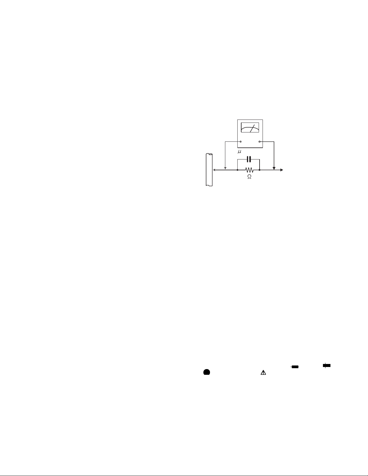
• Alternate check method
Plug the AC line cord directly into the AC outlet. Use an
AC voltmeter having, 1,000Ω per volt or more sensitivity
in the following manner. Connect a 1,500Ω 10W resistor
paralleled by a 0.15µF AC-type capacitor between an ex-
posed metal part and a known good earth ground.
Measure the AC voltage across the resistor with the AC
voltmeter.
Move the resistor connection to each exposed metal
part, particularly any exposed metal part having a return
path to the chassis, and measure the AC voltage across
the resistor. Now, reverse the plug in the AC outlet and
repeat each measurement. Voltage measured any must
not exceed 0.75 V AC (r.m.s.). This corresponds to 0.5
mA AC (r.m.s.).
AC VOLTMETER
(Having 1000
ohms/volts,
or more sensitivity)
0.15 F AC TYPE
Place this
probe on
1500 10W
Good earth ground
1.2 Warning
(1) This equipment has been designed and manufactured to
meet international safety standards.
(2) It is the legal responsibility of the repairer to ensure that
these safety standards are maintained.
(3) Repairs must be made in accordance with the relevant
safety standards.
(4) It is essential that safety critical components are replaced
by approved parts.
(5) If mains voltage selector is provided, check setting for local
voltage.
1.3 Caution
Burrs formed during molding may be left over on some parts
of the chassis.
Therefore, pay attention to such burrs in the case of preforming repair of this system.
1.4 Critical parts for safety
In regard with component parts appearing on the silk-screen
printed side (parts side) of the PWB diagrams, the parts that are
printed over with black such as the resistor ( ), diode ( )
and ICP ( ) or identified by the " " mark nearby are critical for
safety. When replacing them, be sure to use the parts of the
same type and rating as specified by the manufacturer.
(This regulation dose not Except the J and C version)
each exposed
metal part.
1-14 (No.MB713<Rev.002>)
Page 25
1.5 Preventing static electricity
Electrostatic discharge (ESD), which occurs when static electricity stored in the body, fabric, etc. is discharged, can destroy the laser
diode in the traverse unit (optical pickup). Take care to prevent this when performing repairs.
1.5.1 Grounding to prevent damage by static electricity
Static electricity in the work area can destroy the optical pickup (laser diode) in devices such as laser products.
Be careful to use proper grounding in the area where repairs are being performed.
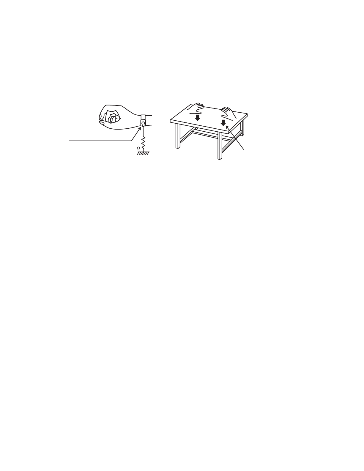
(1) Ground the workbench
Ground the workbench by laying conductive material (such as a conductive sheet) or an iron plate over it before placing the
traverse unit (optical pickup) on it.
(2) Ground yourself
Use an anti-static wrist strap to release any static electricity built up in your body.
(caption)
Anti-static wrist strap
1M
Conductive material
(conductive sheet) or iron palate
(3) Handling the optical pickup
• In order to maintain quality during transport and before installation, both sides of the laser diode on the replacement optical
pickup are shorted. After replacement, return the shorted parts to their original condition.
(Refer to the text.)
• Do not use a tester to check the condition of the laser diode in the optical pickup. The tester's internal power source can easily
destroy the laser diode.
1.6 Handling the traverse unit (optical pickup)
(1) Do not subject the traverse unit (optical pickup) to strong shocks, as it is a sensitive, complex unit.
(2) Cut off the shorted part of the flexible cable using nippers, etc. after replacing the optical pickup. For specific details, refer to the
replacement procedure in the text. Remove the anti-static pin when replacing the traverse unit. Be careful not to take too long a
time when attaching it to the connector.
(3) Handle the flexible cable carefully as it may break when subjected to strong force.
(4) I t is not possible to adjust the semi-fixed resistor that adjusts the laser power. Do not turn it.
(No.MB713<Rev.002>)1-15
Page 26
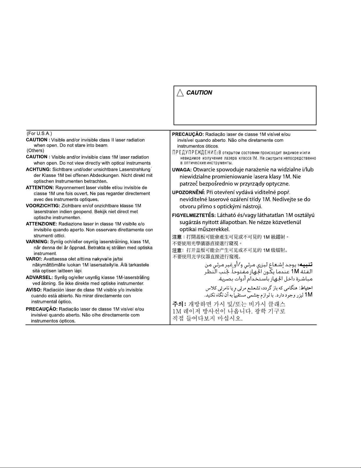
1.7 Important for laser products
1.CLASS 1 LASER PRODUCT
2.CAUTION :
(For U.S.A.) Visible and/or invisible class II laser radiation
when open. Do not stare into beam.
(Others) Visible and/or invisible class 1M laser radiation
when open. Do not view directly with optical instruments.
3.CAUTION : Visible and/or invisible laser radiation when
open and inter lock failed or defeated. Avoid direct
exposure to beam.
4.CAUTION : This laser product uses visible and/or invisible
laser radiation and is equipped with safety switches which
prevent emission of radiation when the drawer is open and
the safety interlocks have failed or are defeated. It is
dangerous to defeat the safety switches.
5.CAUTION : If safety switches malfunction, the laser is able
to function.
6.CAUTION : Use of controls, adjustments or performance of
procedures other than those specified here in may result in
hazardous radiation exposure.
!
Please use enough caution not to
see the beam directly or touch it
in case of an adjustment or operation
check.
SECTION 2
SPECIFIC SERVICE INSTRUCTIONS
This service manual does not describe SPECIFIC SERVICE INSTRUCTIONS.
1-16 (No.MB713<Rev.002>)
Page 27
SECTION 3
DISASSEMBLY
3.1 Main body (Used figure are TH-G61E)
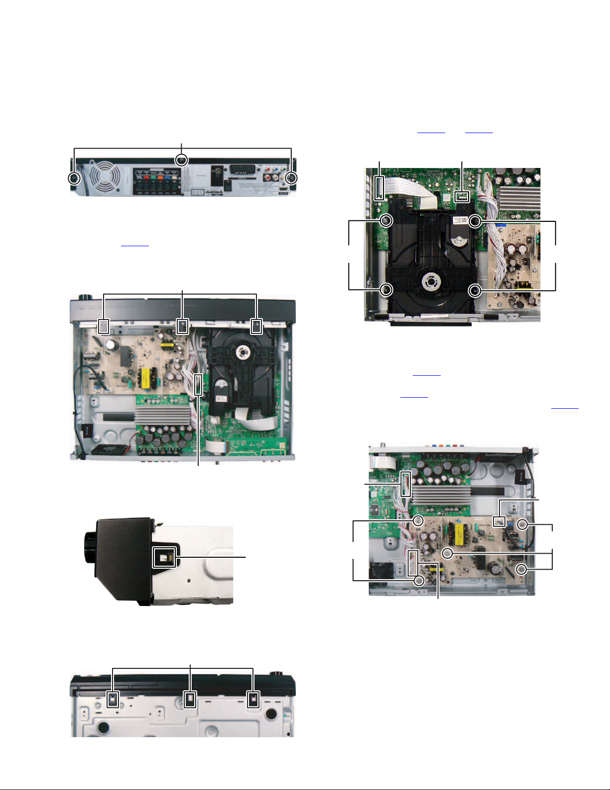
3.1.1 Removing the Top cover (See Fig.1)
Remove the three screws A attaching the Top cover.
(1)
A
Fig.1
3.1.2 Removing the Front panel (See Fig.2, 3 and 4)
(1) Disconnect the card wire from Front panel connected to
connector CN102
(2) Disengage three hooks a engaged the Front panel. (See
Fig.2)
of the Main boards. (See Fig.2)
hook
a
3.1.3 Removing the DVD mechanism (See Fig.5)
(1) Disconnect the card wires from DVD mechanism connect-
ed to connectors CN401
(2) Remove the four screws B attaching the DVD mechanism.
and CN402 of the Main board
CN401CN402
BB
Fig.5
3.1.4 Removing the SMPC board (See Fig.6)
(1) Disconnect the connector wire from SMPC board connect-
ed to connector CN602
(2) Disconnect the connector wire from Main board connected
to connector CN903 of the SMPC board
(3) Disconnect the Power cord connected to connector PN901
of the SMPC board.
(4) Remove the five screws C attaching the SMPC board.
of the Main board.
CN102
Fig.2
(3) Disengage two hooks b engaged both side of the Front
panel. (See Fig.3)
hook
b
Fig.3
(4) Disengaged three hooks c engaged the Front panel. (See
Fig.4)
hook
c
Fig.4
CN602
PN901
C
C
CN903
Fig.6
(No.MB713<Rev.002>)1-17
Page 28
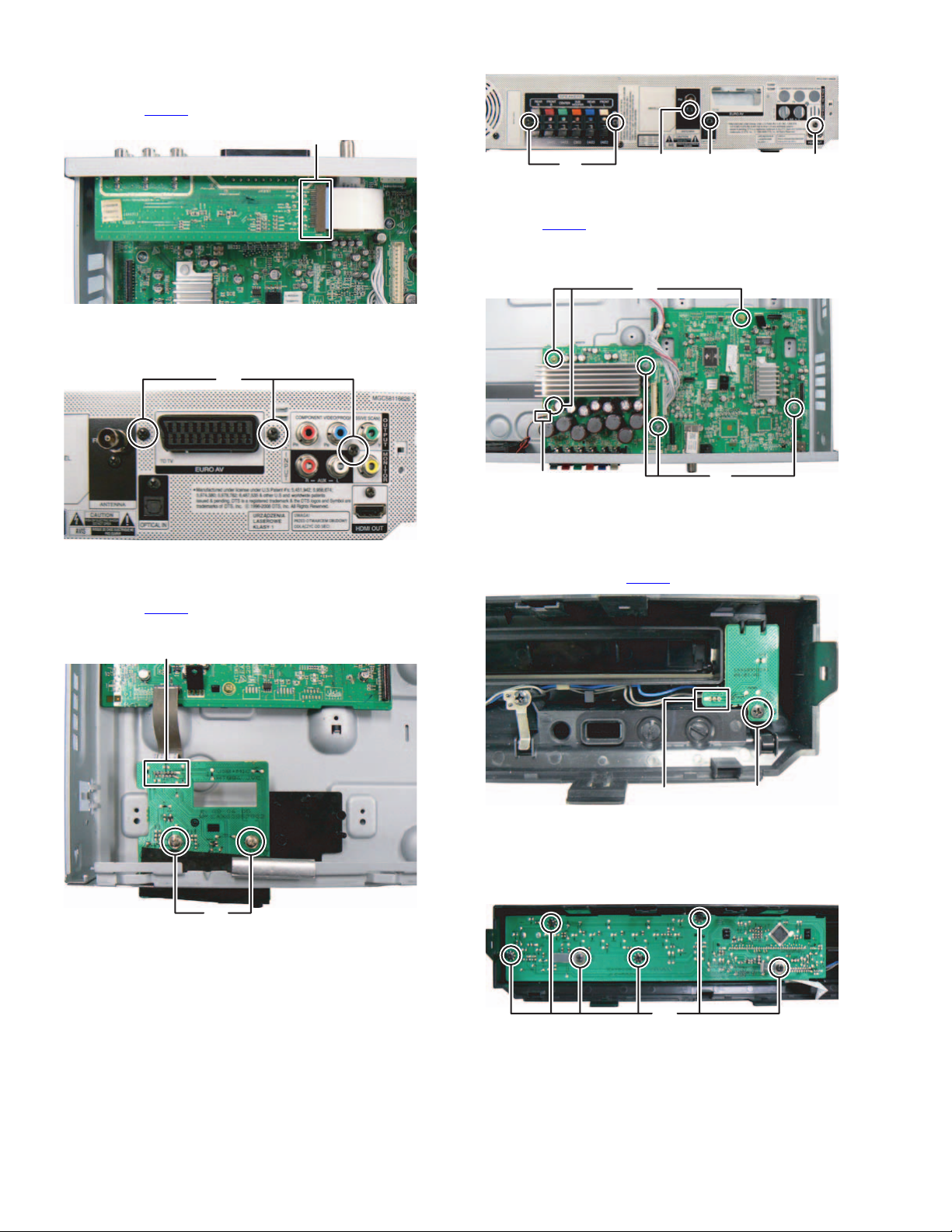
3.1.5 Removing the SCART board (See Fig.7, 8)
(1) Disconnect the card wire from Main board connected to
connector CN250
of the SCART board. (See Fig.7)
CN250
Fig.7
(2) Remove the three screws D attaching the SCART board.
(See Fig.8)
D
Fig.8
3.1.6 Removing the USB board (See Fig.9)
(1) Disconnect the card wire from Main board connected to
connector CN202
(2) Remove the two screws E attaching the USB board.
of the USB board.
CN202
F
(5) Disconnect the connector wire from FAN connected to con-
nector CN603
(6) Remove the three screws K and three screws L attaching
the Main board. (See Fig.11)
of the Mainboard. (See Fig.11)
GH J
Fig.10
K
CN603
Fig.11
3.1.8 Removing the Front key board (See Fig.12)
(1) Remove the one screw M attaching the Front key board.
(2) Disconnect the connector wire from Front timer board con-
nected to connector CN301
L
of the Front key board.
E
Fig.9
3.1.7 Removing the Main board (See Fig.10, 11)
(1) Remove the two screws F attaching the Speaker terminal.
(See Fig.10)
(2) Remove the one screw G attaching the Tuner pack. (See
Fig.10)
(3) Remove the one screw H attaching the Optical jack. (See
Fig.10)
(4) Remove the one screw J attaching the HDMI jack, (See
Fig.10)
1-18 (No.MB713<Rev.002>)
CN301
Fig.12
3.1.9 Removing the Front timer board (See Fig.13)
(1) Remove the volume knob.
(2) Remove the six screws N attaching the Front timer board.
M
N
Fig.13
Page 29
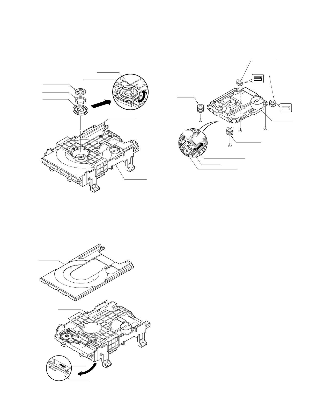
3.2 DVD mechanism
3.2.1 Main base (See Fig.1)
(1) Place the disc clamp assembly as Fig.1.
(2) Lift up the disc clamp assembly in direction of the arrow (A).
(3) Separate the disc clamp assembly from the Clamp holder.
(4) Turn the Clamper plate to counterclockwise direction and
then lift up the clamper plate.
Main base
Disc clamp assembly
Clamper plate
(A)
Magnet clamp
Upper clamp
(Fig. A)
Clamp holder
Main base
Fig.1
3.2.2 Disc tray (See Fig.2)
(1) Insert and push a screwdriver in the emergency eject hole
(A) at the right side, or put the screwdriver on the lever (B)
of the emergency gear and pull the lever (B) in direction of
arrow so that the Disc tray is ejected about 15 ~ 20 mm.
(2) Pull the Disc tray until it is separated from the Main base
completely.
Disc tray
Main base
3.2.3 Slide base assembly (See Fig.3)
(1) Release the four screws (S2).
(2) Disconnect the FFC connector (C1).
(3) Release the screw (S3).
Rubber damper
Distinguish upper and
lower sides
(Assemble with care)
Rubber damper
(S2)
(S3)
(C1)
Reck gear
Spindle motor assembly
(S2)
Rubber damper
(S2)
General pickup assembly
Pickup base
(S2)
Fig.3
3.2.4 Up/Down frame assembly (See Fig.4)
NOTE:
Put the Main base face down (Bottom side)
(1) Release the screw (S4).
(2) Unlock the Locking tab (L3) in direction of arrow and then
lift up the Up/down frame assembly to separate it from
the Main base.
NOTE:
When reassembling move the Up/Down guide in direction of
arrow (C) until it is positioned as Fig (C).
When reassembling insert (A) position of the Up/down frame
assembly in the (B) position of the Up/down frame assembly
as Fig (B).
3.2.5 Pulley gear (See Fig.4)
(1) Unlock the locking tab (L4) in direction of arrow (B) and
then separate the pulley gear from the main base.
3.2.6 Up/down guide (See Fig.4)
(1) Move the Up/down guide in direction of arrow (A) as Fig
(A).
(2) Push the locking tab (L5) down and then lift up the Up/down
guide to separate it from the main base.
NOTE:
When reassembling place the Up/down guide as Fig (C) and
move it direction arrow (B) until it is locked by the locking tab
(L5). And confirm the Up/down guide as Fig (A).
Lever
(B)
Main base
BOTTOM SIDE VIEW
Fig.2
(No.MB713<Rev.002>)1-19
Page 30
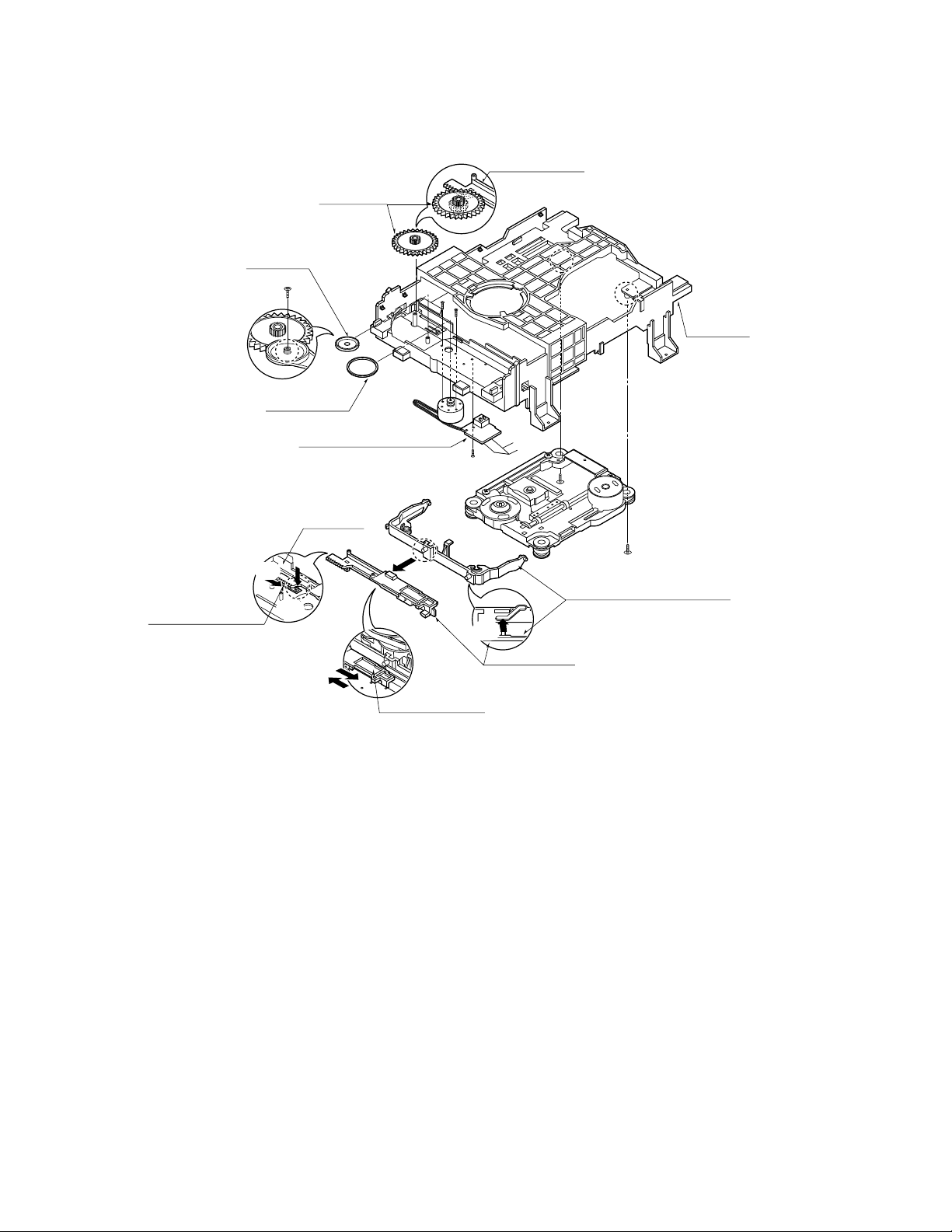
3.2.7 Loading board assembly (See Fig.4)
(1) Release one screw (S5).
(2) Unlock the loading motor (C2) from the hook (H1) on the
main base.
Loading gear
Pully gear
Screw insertion
torque control
(L4)
(3) Unlock two locking tabs (L6) and separate the loading
board assembly from the main base.
Up/Down guide
(L6)
(L6)
Main base
Up/Down guide
Loading belt
(A)
(L5)
FIG. (A)
Loading board assembly
Main base
(A)
(B)
(C)
(B)
Up/Down guide
FIG. (C)
Fig.4
SECTION 4
ADJUSTMENT
(L3)
(C2)
(S5)
(A)
(B)
Up/Down guide
(H1)
(S4)
(S4)
Up/Down frame assembly
FIG. (B)
1-20 (No.MB713<Rev.002>)
This service manual dose not describe ADJUSTMENT.
Page 31

5.1 Power supply circuit
Insert power cord.
SECTION 5
TROUBLESHOOTING
YES
Is the Digitron on correctly?
YES
Turn power on.
YES
Is power on?
YES
Does initial read work?
YES
NO
NO
NO
Check power plug and power
supply circuit.
Check power supply circuit.
Check laser circuit.
Check focus circuit.
Check disc.
Does it play?
YES
Does it output
audio?
YES
OK
NO
Check tracking servo circuit.
NO
Check audio circuit.
(No.MB713<Rev.002>)1-21
Page 32

5.2 Front circuit
Power on.
YES
Blue or Red LED
turn off?
YES
Is the Digitron on
correctly?
YES
Check if all
buttons are ok?
YES
NO
NO
NO
Check if
CN302 and PN331
are ok?
YES
Check if
the front power
is ok?(*1)
YES
Check if
DIS301 is ok?
Check if the
power part of the
front is ok?
YES
Check if
R381~R386, R149
are ok?
NO
NO
NO
Reconnect it.
Refer to SMPS part.
Check pattern and resoldering
NO
Refer to power(SMPS).
NO
Replace R381~R386,
R149.
Check if the
remote control
is ok?
Front B/D ok.
*1 : PN106 Pins.
PIN1 : -34 VKK
PIN2 : -28 FL+
PIN3 : -32 FL PIN12 : +5.6VA
PIN13 : +5V
YES
NO
YES
Refer to MICOM circuit.
Check if the
power part of the front
is ok?
YES
Check if the remote
control waveform of CN302
pin11 is ok?
YES
Check if RC01
voltage is ok(5V)?
YES
Resolder or Replace RC01.
NO
Refer to power(SMPS).
NO
Refer to MICOM circuit.
NO
Check RM circuit
1-22 (No.MB713<Rev.002>)
Page 33

5.3 System operation flow
POWER ON.
1. Initializes SERVO, DSP & RISC registers.
2. Write RISC code to SDRAM.
3. Reset RISC.
Show LOGO.
YES
Tray closed?
NO
Tray close to closed position.
SLED at inner
side?
NO
SLED moves to inner position.
1. Judge whether have disc and disc type.
2. Jump to related disc reading procedure.
Recieve
OPEN/ CLOSE
Key?
NO
YES
NO
1. Execute Pressed Key & IR Key.
2. System operation routine loop.
1. Stop Playback & Open Tray.
2. Display tray open message & LOGO.
YES
Receive
CLOSE Key?
YES
(No.MB713<Rev.002>)1-23
Page 34

5.4 Amp protection
"PROTECTION" appears on the FLD.
After unplug power cord, connect again.
YES
YES
Power on.
YES
"PROTECTION"
appears continuously on
the FLD.
YES
Is the IC101 pin53
"LOW" signal(0V)?
YES
Is the Q703, Q704 and
Q705 normal?
YES
Replace TI AMP IC(IC701, IC702, IC703, IC704)
NO
OK.
NO
Replace IC101.
NO
Replace the Q703, Q704 and Q705.
1-24 (No.MB713<Rev.002>)
Page 35

5.5 AUDIO u-COM circuit (DVD & AMP)
Power On.
YES
Does
CD/DVD appear at
FLD?
YES
Does
Reading appear
at FLD?
YES
Does
no Disc or Time
appear at
FLD?
YES
Check
if DVD/CD insert
is OK.
NO
NO
Does it
appear DVD Error
at FLD?
YES
Check
power part of
Main B/D.
YES
Check
oscillator of
X100.
Does
AV1,TV AUDIO,
AV1 OPT and FM 87.5
appear at
FLD.
NO
NO
Refer to SMPS.
NO
Refer to oscillator circuit.
YESNO
OK
NO
YES
NO
Check Power.
Check
if IC101 Pin29
is high.
YES
YES
Check if
Check DVD Module. Check 5V line.
IC101 Pins 14,40,
55,89 are high
NO
Check IC101 Pin29
reset waveform.
NO
(5V).
YES
Check SMPS.
Check
if IC101 Pin58
is high.
NO
Check power section
circuit.
YES
Replace IC101.
(No.MB713<Rev.002>)1-25
Page 36

Victor Company of Japan, Limited
Home Entertainment Business Division Personal AV Operation 10-1,1chome,Ohwatari-machi,Maebashi-city,371-8543,Japan
(No.MB713<Rev.002>)
Printed in Japan
VSE
Page 37

SCHEMATIC DIAGRAMS
DVD DIGITAL CINEMA SYSTEM
TH-G61E, TH-G61EN, TH-G61A,
TH-G61UX, TH-G61UN, TH-G41A,
TH-G41UX, TH-G31B, TH-G31E,
TH-G31EN, TH-G31A, TH-G31UX,
TH-G31UN, TH-G61UH, TH-G31UH
DVD-ROM No.SML2009S2
TH-G31
SP-THG50W
SP-THG61C
TH-G61
SP-THG61F
SP-THG50W
SP-THG51F
Lead free solder used in the board (material : Sn-Ag-Cu, melting point : 219 Centigrade)
XV-THG61
iPod is a trademark of Apple Inc.,
registered in the U.S. and other countries.
iPhone is a trademark of Apple Inc.
A only
Contents
Block diagrams
Standard schematic diagrams
Printed circuit boards
SP-THG61C
Europe only
SP-THG51F
SP-THG51F
TH-G41
SP-THG51F
XV-THG31
SP-THG50W
iPod is a trademark of Apple Inc.,
registered in the U.S. and other countries.
iPhone is a trademark of Apple Inc.
SP-THG61C
XV-THG41
SP-THG51F
Europe only
SP-THG51F
2-1
2-2
2-17 to 20
COPYRIGHT 2010 Victor Company of Japan, Limited.
No.MB713SCH<Rev.002>
2010/01
Page 38

In regard with component parts appearing on the silk-screen printed side (parts side) of the PWB diagrams, the
parts that are printed over with black such as the resistor ( ), diode ( ) and ICP ( ) or identified by the " "
mark nearby are critical for safety.
Page 39

Block diagram
OPTICAL
IN
USB
HDMI
IN
HDMI
OUT
Portable
W/TX
Module
Aux-IN
TUNER
iPod
MIC
SCART
SPDIF
D+, D-
TMDS
TMDS
27 MHz
HDMI
RX SPDIF
RX
12bit
VIDEO
12bit
HDMI
TX
RST
MCLK, BCLK, LRCK, DATA, SCL,
SCART AUDIO
12bit
MCLK,BCLK
LRCLK,DATA
AUX AUDIO
TX/RX
SW
12bit
VIDEO
IC201
TUNER AUDIO
CS5346
(ADC)
PORT AUDIO
IPOD AUDIO
IC2A1
S4308
MIC L/R
SPDIF
SW
MCLK,BCLK
LRCLK,DATA
SDA
LRCLK, BCLK
5345_DATA
DVD_RESET
SW_SPDIF
MCLK
DVD_RX
X100
9.8304 MHz
IC101
AUDIO
MICOM
(100Pin)
DVD_TX
IC501
MT1389MH
(176PIN)
DB[0-15]
DMA[0-10]
SCL
27 MHz
SDA
9830_DAT
9830_RESET
9830_CLK
SCL
SDA
AMP BOARDMAIN BOARD
6315_DO
X601
12.288 MHz
IC601
PWM
MODULATOR
(PS9830)
FOCUS/SLED
SPINDLE/TRACKING
6315_CLK
6315_DI
6315_STB
ET16315
VFD
DRIVER
LRCLK, BCLK
FRONT(ADATA0)
REAR(ADATA1)
C/W(ADATA2)
D/M(ADATA3)
OPEN/CLOSE
TAS5352_PDN
TAS5352_SD
FL+/-, FR+/-
RL+/-, RR+/CENTER+/WOOFER+/-
IC400
Motor
Driver
TAS5352
Power Amp
(IC701~704)
A, B, C, D, E, F, RF
MD_DVD, MD_CD
LD_DVD, LD_CD
VR_DVD, VR_CD
F+/-, T+/-
FL
FR
RL
RR
C/T
S/W
PICK-UP
Composite
Component
R, G, B
Y, Pb, Pr
MPEG Composite
IC250
MM1692
Y/G, Pb/B, Pr/R
Y, C
IC503
SDRAM
IC502
FLASH
IC504
EEPROM
GR[1-12]
SG[1-16]
VFD
SLED+/-
Motor
SPINDLE+/LOAD+/-
2-1
Page 40

Standard schematic diagrams
E
SMPS CIRCUIT DIAGRAM
TJC3965-3A-2Z
KMQ451VSN151MR25S_DIA30X25L
C935 C901
++
AC250V_8A
PN901
F901
3
250V 8A
1
C904
2kV_1500pF
KMQ451VSN151MR25S_DIA30X25L
B72210-52421-K101
VR901
SPA08N80C3
Q904
SPA08N80C3
1SS133
ZD974
MTZ_J27
CM903
AC300V_0.33uF
LFS2825V2-21250
Q901
D982
1SS133
R901 R902
2W_0.15 2W_0.1
1SS133
D937
D981
ZD977
MTZ_J27
LF901
AC250V_1000pF
1SS133
D904
R904
1/10W_120
R943
1/16W_33
R942
1/10W_120
ZD903
RD27E
AC250V_1000pF
C906
C907
1-16W_33
R905
100
R941
8
7
50V_470pF
1/16W_120
R908
CM908
6
SSC6700
IC901
15
50V_0.1uF
C909C934
50V_470pF
R903
AC300V_0.22uF
2
4
3
C905
C912
1/2W_1M
LFS2828V2-21250
TH901
SCK-054
1W_330k
MTZ_J36
50V_4700pF
ZD975
R910
1/16W_150k
LF902
R936
OPEN
R911
+
C913
50V_4.7uF
ZD972
MTZ_J10
D5SBA60
1W_330k
R937
PS2571L1-1
PC901
4
3
MTZ_J6.2
1/16W_1k
R914
ZD906
C910
50V_1000pF
50V_22000pF
C914
R944
1/16W_47k
1SS133
D936
BD901
1/16W_1k
2SA1037AK
1/10W_470k
R931
1SS133
R932
D931
C931
R933
Q931
25V_0.47uF
1/16W_10k
1W_220k 1W_220k
R919
3W_6.8
R976
3W_6.8
R977
3W_6.8
R978
D902
SARS02
D901
SARS02
1SS244
D905
1SS244
D914
C932
KTC3198
Q902
R918
1/16W_820
KMF500ETC4R7ME11D(RL-2000)
D907
1SS133
50V_220pF
IMPORTANT SAFETY NOTICE
WHEN SERVICING THIS CHASSIS, UNDER NO
CIRCUMSTANCES SHOULD THE ORIGINAL DESIGN BE
MODIFIED OR ALTERED WITHOUT PERMISSION
FROM THE JVC CORPORATION. ALL COMPONENTS
SHOULD BE REPLACED ONLY WITH TYPES IDENTICAL
TO THOSE IN THE ORIGINAL CIRCUIT.
FNS(136)400V153J_A_(ROHS)
FNS(135)630V103J_STRL_(ROHS)
R921
1/16W_4.7k
R906
C933
C915
50V_220pF
OPEN
R938
C916
1SS244
D942
AV250V_1000pF
C917
1/16W_47
R923
D970
1SS244
MTZ_J27
1/16W_3.3k
1/16W_3.3k
R980R981
D971
4. 5
6. 7
1
1kW SDT 38
T901
2
FMKS-2152
9. 10. 11.1 2
13. 14. 15. 16
SPECIAL COMPONENTS ARE SHADED ON THE
SCHEMATIC FOR EASY IDENTIFICATION.
THIS CIRCUIT DIAGRAM MAY OCCASIONALLY DIFFER
FROM THE ACTUAL CIRCUIT USED. THIS WAY,
IMPLEMENTATION OF THE LATEST SAFETY AND
PERFORMANCE IMPROVEMENT CHANGES INTO
THE SET IS NOT DELAYED UNTIL THE NEW SERVICE
LITERATURE IS PRINTED.
KTC3875
1/16W_22k
Q961
ZD980
MTZ_J6.2
C965
MTZ_J8.2
Z960
1/16W_22k
MTZ_J6.2
BL02RN1
FB957
50V_47000pF
DTC114EKA
ZD961
KTC3875
50V_4700pF
L951
RK16
Q962
Q959
KTC3875
Q954
R967
R988
1/16W_68k
C981
D953
D968
RK16
C951
D967
2
C963
KY-500ETD102M_25S(RL-250)16X25
BL02RN1
FB956
D973
11E0504
D990
1SS133
R992
1/16W_33k
C964
++
KY-500ETD102M_25S(RL-250)16X25
50V_4700pF
C976
+
C960
KMF500ETD471MK20S(RL-500)
+
R951
OPEN
1
SI-80335
C980
OPEN
1/2W_2.2k
KTC3875
R952
C952
1/16W_120
OPEN
IC951
3
OPEN
R987
D976
R993
Q951
2
54
Q960
50V_4700pF
10ERB20
D955
1 2. 3
50V_47000pF
MTZ_J188
ZD978
1/16W_68k
R990
C982
1/16W_10k
D979
1SS133
C967
NOTE :
1. Voltages are DC-measured with a digital voltmeter
during Play mode.
PS2571
1/16W_3.3k
PC901
R991
50V_4700pF
1SS133
D978
KTC3875
Q953
C959
EK16
D954
1/16W_0
R968
1/16W_47
R956
1/16W_390
R957
1
1/16W_10k
R972
1/16W_330
Q957
R965
50V_0.1uF
1/16W_10k
EK16
D951
7634510
KMF100ETD102MU16S(RL-800)
2
R964
R953
1/16W_2.2k
MTZ_J12
ZD958
IC952
C980
KIA431
UPS1E101MED1TA_6.3X11(RL-2000)
KMF100ETD102MJ16S(RL-800)
+
C954
10V_100uF
10ERB40
1/2W_100
R979
1/10W_100k
D952
C955
+
9
UPS1H470MED1TA_6.3X11(RL-2000)
+
C956
1/10W_120k
R954
R961
1/10W_11k
R960
1/10W_3.3k
50V_470pF
R994
C953
R955
OPEN
1/16W_10k
R959
+
+
C957
C958
MTZ_J2.7
ZD959
R958
BL02RN1
FB952
50V_0.1uF
ZD976
MTZ_J24
UPS1H470MED1TA_6.3X11(RL-2000)
BL02RN2
FB953
BL02RN1
FB954
50V 0.1uF
C966
50V 0.1uF
C696
50V_0.1uF
C967
C974
C968
50V_0.1uF
R966
+
1/16W_100k
C978
C983
50V_0.1uF
CN902
CN903
+36V
1
+36V
2
+36V
3
+36V
4
P-SENS
13
11
P-CTAL
14
GND
+12V
12
5
GND
6
GND
7
GND
8
GND
9
GND
10
GND
+12V
11
+5V
3
2
+5V
14
FL+
13
FL-
15
VKK
10
+3.8V
9
+3.8V
8
+3.8V
7
GND
GND
6
12
GND
CHANGES C901 C935 Q901 Q904 C904 C951 R902 BD91LF902LF901
3H266L
110V
3H266H
220V
3H266W-1
CIS
3H266W
WODE
220V 330uF
420V 100uF
500V 150uF
450V 150uF
OPEN
OPEN
500V 150uF
450V 150uF
2SK3569
2SK3677
SPA08N80C3
SPA08N80C3
18mH
(SIZE SMALL)
25mH
25mH
25mH
-
1KV
1000pF
-
-
-
400V
2200pF
-
-
-
2W 0.15
-
-
-
D3SBA60
-
-
NOTES) Symbol denotes AC ground.
NOTES) Symbol denotes DC chassis ground.
2-2
+
C971
KMF500ETD471MK20S(RL-500)
IC953
1
SI-8008TM
4
11E0S06-TA1B2_(RL-2000)
PJ10Z-221
L952
R984
1/16W_4.7k
R985
1/16W_220
R986
1/10W_820
KMF100ETC471MHB5D(RL-1000)
BL02RN1
FB951
+
ZD973
C972
MTZ_J24
50V_0.1uF
+
C979
C975
KMF350ETC101MHB5D
4
+5.6V
5
+5.6V
1
GND
BL02RN1
FB957
2
5
3
D974
C973
50V_4700pF
Page 41

MPEG CIRCUIT DIAGRAM
C561
47/6.3
C560
47/6.3
XX
DGND
ZD501
STZ5.6N
SF_CLK
SF_DI
DD15
DD14
DD13
DD12
DD11
DD10
DQM1
SDCLK
DA11
C529
0.1uF
SCL
SDA
DD9
DD8
DA9
DA8
DA7
DA6
DA5
DA4
IOA
IN_SW
OUTSW
PU_DET
CLOSE
OPEN
M_STBY
VREF
SVREF
MDI
CDLD
DVDLD
SPN+
SPNRF
F
E
A
B
C
D
FOD
TRD
SLD
SPIND
MP_HDMI_SDA
MP_HDMI_SCL
HPLUG
TX2+_MPEG
TX2-_MPEG
TX1+_MPEG
TX1-_MPEG
TX0+_MPEG
TX0-_MPEG
TXC+_MPEG
TXC-_MPEG
SPDIF_OUT
MCLK
IPOD_DI
IPOD_DO
IPOD_CE
IPOD_CLK
SPI_DI
SPI_DO
SPI_CE
SPI_CLK
RESET_IN
R518
ADATA0
ADATA1
ADATA2
LRCK
BCK
USBP
USBN
MIC_L
MIC_R
SPMCLK
SPBCK
SPLRCK
SPDATA
V_MUTE
CVBS
Y_G
PB_B
PB_R
33
ZD500
STZ5.6N
AMC2012H
14
23
+
+
AGND
F501
R552
75
DGND
R528C554 10/16 0
R521C553 10/16 0
R553
75
R523
C551
0.1uF
100
DVD_RESET
R554
75
R555
75
IOA
IN_SW
OUTSW
PU_DET
CLOSE
OPEN
M_STBY
VREF
SVREF
MDI
CDLD
DVDLD
SPN+
SERVO
SPNRF
F
E
A
B
C
D
FOD
TRD
SLD
SPIND
MP_HDMI_SDA
MP_HDMI_SCL
HPLUG
TX2+_MPEG
TX2-_MPEG
TX1+_MPEG
TX1-_MPEG
TX0+_MPEG
TX0-_MPEG
TXC+_MPEG
TXC-_MPEG
SPDIF_OUT
MCLK
IPOD_DI
IPOD_DO
MICOM
IPOD_CE
IPOD_CLK
SPI_DI
SPI_DO
MICOM
SPI_CE
SPI_CLK
DVD_RST
ADATA0
ADATA1
ADATA2
DSP
LRCK
BCK
USB_P
USB_N
MIC_SIG
SPMCLK
SPBCK
SPLRCK
SPDATA
V_MUTE
CVBS
Y_G
PB_B
PB_R
HDMI TX
I/O
VCC33
VDD
HOLD#
SCK
SIVSS
C564
10/16
R522
R505
VSS54
DQ15
VSSQ52
DQ14
DQ13
VDDQ49
DQ12
DQ11
VSSQ46
DQ10
DQ9
VDDQ43
DQ8
VSS41
NC40
UDQM
CLK
CKE
NC36
A11
A9
A8
A7
A6
A5
A4
VSS28
DGND
L506
HH-221
C563
10/16
R530
10K
8
T513
T511
7
T512
6
T514
54
C541
C528
8P
NC
C535
8P
DGND
+
C542
0.1uF
DGND
R524
4.7K
54
53
52
51
50
49
48
47
46
45
44
43
42
41
40
39
38
37
36
35
34
33
32
31
30
29
2827
33
33
VCC33
C565
10/16
0.1uF
0.1uF
R506
10K
C531
0.1uF
C525
C533
L507
HH-221
R513
4.7K
C571
1K:High speed
4.7K:Low speed
C566
0.1uF
BA0
BA1
DA0
DA1
DA2
DA3
OUT
DA10
CAS#
0.1uFC512
107
108
RA3
USB
_
VDD18
0.1uF
C505
_
DET
PU
RA2
YCLK
RAS#
DWE#
0.1uFC511
100
101
102
103
104
105
106
RA1
Y0
_
DV
R541 33
CLK
_
IPOD
IOA
_
_
BA0
BA1
RA0
RA10
CAS_RAS
GND18
DVDD33
_
Y7
Y6
Y5
Y4
Y3
Y2
Y1
CS
_
_
_
_
_
_
_
_
_
SF
DV
DV
DV
DV
DV
DV
DV
R543 33
R542 33
DI
DO
_
_
DO
CS
_
_
SF
SF
IPOD
IPOD
MPEG
_
TXC-
0.1uFC513
114
115
116
117
TX
_
TX2
_
VPLL
TXCP
TXCN
_
AGND33
AGND18
AVDD33
IC501
MTK1389MH
FG/GPIO2
FOO
TRO
TRAY_CLOSE
TRAY_OPEN
SW
STBY
_
TN
M
FOD
TRD
OPEN
HPLUG
2.7K(1%)
R527
111
112
113
RES
VPLL
_
_
EXT
AGND33
_
DP
DM
_
_
USB
USB
0.1uF
C504
5.1K(1%)
R500
AGND
USBP
USBN
_
SPDIF
109
110
DVDD18
GPIO10/HPLG
SPDIF/GPIO12
USB
USB
_
VRT
_
PAD
VSS33
VDD33
C530
NC
MPEG
MPEG
MPEG
MPEG
MPEG
MPEG
MPEG
_
_
_
_
_
_
C545
0.1uF
130
131
132
NC
AGNDC
DACVDDA
G
AGNDC
B
R
AADVSS
AKIN2/GPIO19
ADVCM/GPI0
AKIN1/GPIO21
AAVDD
APLLVDD
APLLCAP
APLLVSS
ADACVSS2
ADACVSS1
LFE/GPIO
ARS/GPIO
AR/GPIO0
AVCM
AL/GPIO1
ALS/GPIO
CENTER/GPIO
ADACVDD1
ADACVDD2
AVDD18_1
AGND18
RFIP
RFIN/OPOUT
RFG/OPINP
RFH/OPINN
RFA
AVDD18_2
XTALI
AVDD33_1
0.1uF
0.1uF
C502
C501
R501
15K
129
NCNCNC
XTALO
TX2+
127
128
TXD
TX2P
_
AVDD18
V20
AGND33
VREF
_
TX2-
0.1uFC515
125
126
TX0
_
TX2N
AVDD18
REXT/GPO5
V14
CLOSE
SVREF
TX1+
124
987654321
MDI
TX1P
MDI1
TX1-
123
TX1N
10
CDLD
122
TX1
_
AGND18
LDO2
LDO1
DVDLD
TX0+
121
TX0P
AVDD33_2
0.1uF
C503
TX0-
120
TX0N
DMO
SPIND
0.1uFC514
119
TX1
_
AVDD18
SLD
TXC+
118
FMO
_
AGND
C540
0.1uF
R529
X500
27MHz
VCC18
L503
HH-221
+
C556
47/6.3
DACVDDC
VREF/GPO14
560
DACVSSC
CVBS
DACVDDB
RFC
RFD
RFE
RFF
100KR502
22pF
DGND
NC
FS
C523
DGND
133
134
135
136
137
138
139
140
141
142
143
144
145
146
147
148
149
150
151
152
153
154
155
156
157
158
159
160
161
162
163
164
165
166
167
168
169
170
171
172RFB
173
174
175
176
VCC33
L504
HH-221
+
C558
47uF/16V(MODI)
C520
RFGND
AGND
C567
C547
C546
C519
C518
C517
C516
C538
C500
120pF
0.1uF0.1uF
0.1uF
0.1uF
0.1uF
0.1uF
1500pF
0.1uF
120pF
1U
C521
22pF
VCC18
C557
47/6.3
R545
R546
R547
R549
R550
R551
C537
XX(120pF)
C543
L505
HH-221
+
33
33
33
33
33
33
C568
C569
C544
0.1uF
XX
XX
V_MUTE
CVBS
PB_B
Y_G
PB_B
PA_A
MIC_L
MIC_R
+
C532
0.1uF
MCLK
BCK
ADATA 2
ADATA 1
+
C552
LRCK
0.1uF
ADATA 0
RF
SPN+
SPNB
C
D
A
F
E
DGND
RWE
DO
SF
DI
_
SF
DA4
GND33
DI
_
SF
C506
DA6
DA5
0.1uFC510
RA6
RA5
RA4
GPIO7/CKE
SD_MS_D3
SD_MS_D2
SD_MS_D1
SD_MS_D0
SD_MS_CMD
SD_MS_CLK
6/SCL
_
CK
_
DVDD33
SF
UP1
3938373635343332313029282726252423222120191817161514131211
40
0.1uF
33
R531
SCL
_
_
HDMI
CLK
_
_
_
SF
MP
DA9
DA8
DA7
8990919293949596979899
RA8
RA7
DQM1
DVDD33
RD8
RD9
RD10
RD11
RD12
RD13
DVDD18
RD14
RD15
DQM0
RD7
RD6
RD5
RD4
RD3
RD2
RD1
RD0
DVDD33
GPIO8
GPIO9
GPIO13
DVDD33
DV_C7
DV_C6
DV_C5
DV_C4
DV_C3
DV_C2
7/SDA
_
GPIO6
GPIO11
UP1
434241
44
33
R532
RXD
TXD
_
_
SDA
IN
_
HDMI
RESET
MP
DOWNLOAD
DOWNLOAD
RA9
_
_
PRST
C573
47/16
+
RA11
88
RCLK
87
86
85
84
83
82
81
80
79
78
77
76
75
74
73
72
71
70
69
68
67
66
65
64
63
62
61
60
59
58
57
56
55
54
53
52
51
50
DV_C1
49
DV_C0
48
GPIO4
47
GPIO3 / INT
46
IR
45
2
VCC18
L502
VCC50
3
_
Q503
2SK3018
1
HH-221
C559
47/6.3
EMUL
3.3V
RXD
TXD
GND
CN501
VCC33
L501
HH-221
C555
47/16
+
C549
0.1uF
DGND
VCC33
T502
4
T500
3
T501
2
T503
1
DGND
+
C536
0.1uF
DGND
DOWNLOAD_RXD
DOWNLOAD_TXD
KARAOKE MODEL : 4M
NON KARAOKE : 2M
SF_CS
SF_DO
R509
10K
R508
R526
10K
1K
C526
8P
C548
30P
DGND
T509
T507
T515
T510
C539
8P
R511
IC502
NC/10K
1
CE#
2
SO
3
WP#
MX25L3205D
VCC33
IC504
T506
8
VCC
7
WC
T504
6
SCL
T505
5
SDA
CN502
GND
SCL
SDA
GND
1
2
3
4
IC503
1
VDD1
2
DQ0
3
VDDQ3
4
DQ1
5
DQ2
6
VSSQ6
7
DQ3
8
DQ4
9
VDDQ9
10
DQ5
11
DQ6
12
VSSQ12
13
DQ7
14
VDD14
15
LDQM
16
/WE
17
/CAS
18
/RAS
19
/CS
20
BA0
21
BA1
22
A10/AP
23
A0
24
A1
25
A2
26
A3
VSS27
HY57V641620HG
C509
C508
C507
0.1uF
0.1uF
0.1uF
DGND
C570
XX
R525
33
R519 33
R517 33
R503 33
R512 33
R507 33
R504 33
33
R520
R514
33
R516
33
R515
0
R540
33
C572
5pF
DGND
R5560R5570R558
DGND
PGND
SDCLK
DQM1
DQM0
SPI_DI
SPI_DO
SPI_CE
SPI_CLK
SPDATA
SPLBCK
SPBCK
SPMCLK
OUTSW
IPOD_CE
ICDGND
0
DA11
DD10
DD11
DD12
DD13
DD14
DD15
DD8
DD9
DD7
DD6
DD5
DD4
DD3
DD2
DD1
DD0
SDA
SCL
DD0
DD1
DD2
DD3
DD4
DD5
DD6
DD7
DQM0
DWE#
CAS#
RAS#
BA0
BA1
DA10
DA0
DA1
DA2
DA3
T508
DGND
1
E0
2
E1
3
E2
4
GND
KS24C021CS
DGND
C527
0.1uF
C522
0.1uF
C534
0.1uF
C550
0.1uF
R510
10K
C524
0.1uF
2-3
Page 42

SERVO CIRCUIT DIAGRAM
5V_MOTOR
MVCC
VCC33
V33_M
FROM PICKUP
CN402
NC/FHM-VCC
RF
DVD_LD
MON(COM)/5V
DVD_VR
GND
VREF/VC
VCC
F
E
A
D
C
B
F(+)
T(+)
T(-)
F(-)
SW_PDIC
GND
CD_LD
MON/MPD
CD_VR
L403
HH-221
VCC33
L404
HH-221
Q404
2SA1037K
Q402
2SA1037K
R455
RFGND
0
R401
10K
C419
100u/6.3V
R440
10K
D406
RS1G
+
R435
33K
CDLD
DVDLD
IOA
VREF
SVREF
MDI
SPN+
SPNOPEN
CLOSE
M_STBY
RF
F
E
A
B
C
D
FOD
TRD
SLD
SPIND
MVCC
+
C410C420
MGND
MGND
0.1uF
C427
47/16
0
R456
CDLD
DVDLD
M_STBY
IOA
SVREF
VREF
TRD
56K
C400
220pF
MGND
R449
R450
C407
0.022uF
4.7K
+
C428
0.1
R437
6.2K
R415
10K
MGND
SPIND
SVREF
MDI
SPN+
SPN-
OPEN
CLOSE
M_STBY
R432
R416
2.2K
10K
SP-
RF
F
SP+
E
T-
A
T+
B
C
D
FOD
TRD
SLD
SPIND
MGND
100u/6.3V
28
27
26
25
24
23
22
30
21
20
19
18
17
16
15
C416
0.1uF
L405
HH-221
IC400
1
VINFC
MUTE
2
TRB_1
REGO 2
VINSL+
REGO 1
FWD
REV
GND
Vcc1
VOTR-
VOTR+
VOSL+
VOSL-
VOFC-
VOFC+
AM5890S
BIAS
VINTK
TRB_2
RESET
VINLD
GND
GND
VCTL
VCCD
Vcc2
VOLD-
VOLD+
VOTK-
VOTK+
3
4
5
6
7
29
8
9
10
11
12
13
14
Q406
RFGND
FOD
SLD
OPEN
CLOSE
LOAD+
LOAD-
SL+
SL-
F-
F+
C422
100u/6.3V
R448
R451
KTC3875
IOA
+
MGND
10K
R408
MGND
C405
0.1uF
27K
22K
R411
1K(1%)
RFGND
R428
100K
VCC18
R446
510(1%)
Q412
KTA1666
C
Q410
2SK3018
1
3
2
VR_CD
D405
RS1G
E
B
C401 C402
270pF 0.1uF
V33_M
RFGND
MVCC
C421
100u/6.3V
+
MGND
10K
L409
HH-221
+
R442
R447
C418
47U/6.3V
100K
R405
220K
R445
10K
R404
Q408
KTC3875
100K
3
RFGND
1
2
Q411
2SK3018
VR_DVD
DVDLD
CDLD
PU_DET
VR_DVD
VREF
VR_CD
RF
F
E
A
D
C
B
F+
T+
T-
F-
IOA
MDI
VCC50
L402
HH-221
+
C423
100u/6.3V
T428
1
T435
2
T452
3
T427
4
T442
5
T444
C411
L400
0.1uF
HH-221
+
RFGND
6
T423
7
T447
8
T429
9
T445
10
T453
11
T425
12
T439
13
T440
14
T443
15
T424
16
T448
17
T437
18
T432
19
20
T436
21
T434
22
T430
23
C408
0.1uF
RFGND
C404
0.1uF
RFGND
R402
2.2
Q405
2SA1980SY(KTA1504S)
C413
0.1uF
C426
47/16
C412
0.1uF
RFGND
L408
HH-221
VCC33
+
C417
47U/6.3V
2SA1980SY(KTA1504S)
L401
HH-221
Q403
R443
2.2
CN401
LM-
LM+
OPEN
CLOSE
GND
FM+
FM-
SP+
T449
1
T450
2
T426
3
T451
4
T438
5
6
7
8
9
SP-
R410
10K
T421
T431
T422
T441
R409
10K
MGND
MGND
C409
0.1uF
R453
1 (2012Type)
R407
10K
R444
10K
MGND
C403
0.1uF
D400
3
2
1
XX
VCC33
LOAD-
LOAD+
OUTSW
IN_SW
SPN+
SPN-
VCC33
SL+
SL-
SP+
SP-
OUTSW
IN_SW
PU_DET
4.7K
R457
4.7K
R434
OUTSW
IN_SW
PU_DET
2-4
Page 43

I/O CIRCUIT DIAGRAM
CS5346_RST
HDMI RX
HDMI_SPDIF
CVBS
PR_R
PB_B
Y_G
V_MUTE
MIC_SIG
SPDATA
SPBCK
MPEG
SPLRCK
SPMCLK
LRCK
BCK
DSP_DATA0
DSP_DATA1
DSP
IPOD_L
IPOD_R
PTB_L
PTB_R
I/O
TUNER_L
TUNER_R
MIC_INPUT
MICOM
DIR_RST
CS5346_RST
ADC/DIR_CLK
ADC/DIR_DAT
WIRELESS_SW
16:9/4:3
TV_MODE
RGB_VIDEO
DIR_INT
IPOD_VIDEO_MUX
IPOD_VIDEO
HDMI_SPDIF
CVBS
PR_R
PB_B
Y_G
V_MUTE
MIC_SIG
SPDATA
SPBCK
SPLRCK
SPMCLK
LRCK
BCK
DSP_DATA0
DSP_DATA1
IPOD_L
IPOD_R
PTB_L
PTB_R
TUNER_L
TUNER_R
MIC_INPUT
DIR_RST
CS5346_RST
ADC/DIR_CLK
ADC/DIR_DAT
WIRELESS_SW
16:9/4:3
TV_MODE
RGB_VIDEO
DIR_INT
IPOD_VIDEO_MUX
IPOD_VIDEO
AUX_L
AUX_R
S_AUDIO_L
S_AUDIO_R
PTB_L
PTB_R
TUNER_L
TUNER_R
IPOD_L
IPOD_R
10/16
C201
+
10/16
C202
+
10/16
C214
+
10/16
C215
+
WITH SCART
C203
10/16
+
C204
10/16
+
C205
10/16
+
C206
10/16
+
R219 39K
R220 39K
R223 39K
R224 39K
AGND
R217
39K
R218
R239 0
R240 0
R221 12K
R222 12K
AGND
39K
C213
C209 2200p
C210
C211
C216
C212
C217
+
2200p
+
0.1U
+
0.1U
47/16
10/16
10/16
VCC50
L201
R251
10K
HH-221(2)
C218
0.1U
13
14
15
16
17
18
19
20
21
22
23
24
12111098765432
AIN1B
AIN2B
AIN2A
AIN1A
AGND
VA
AFILTA
AFILTB
VQ
TSTO
FILT+
TSTO
AIN4A/MICIN1
AIN4B/MICIN2
AIN5A
AIN5B
C268
CS5346
IC201
SLAVE
MICBIAS
AIN6A
AIN6B
PGAOUTA
2526272829303132333435
1U
DGND
AIN3B
AIN3A
RESET
PGAOUTBVAAGND
AGND
2.2K
R2E8
DGND
0.1U
C220
VLC
AD1/CDIN
AGNDNCNC
R225
AD0/CS
1K
1
SCL/CCLK
SDA/CDOUT
DGND
MCLK
LRCK
SCLK
SDOUT
TSTO
VLS
36
C221
0.1U
0VFL
TSTI
R235 R236
XX(75) XX(75)
DGND
VCC33
L204
HH-221(2)
C229
10/16
+
0.1U
C230
VA
AGND
RZ1/RXN0
RX2/RXP1
VD_FILT
DGNDVLSDOUT2
+
C231
0.1U
OPT_IN
DGND
C234
0.01U
C232
0.01U
1
RZ0/RXP0
OLRCK1
OSCLK1
SDOUT1
TDM_IN
OLPCK2
OSCLK2
24
C233
0.1U
RST
RMCK
GPO3
DIR_RST
VCC33
CAP CLOSE TO JACK
OPT_IN
L205
HH-221
C235
0.1U
DGND
VCC50
32
JK201
1
JSR1164-B
+12V
TO I/O BOARD
CN201
1
PR/R
2
12V
3
5V
4
PB/B
T205
5
AGND
6
Y/G
7
AGND
8
CVBS
9
16:9/4:3
10
TV_MODE
11
RGB_VIDEO
12
AUX_L
13
AGND
14
AUX_R
15
AGND
16
S_AUX_R
17
COMPOSITE_MUTE
18
S\AUX_L
19
IPOD_VIDEO_MUX
20
IPOD_VIDEO
IPOD MODEL ONLY
ICDGND
R254
390
T201
T202
T203
T204
T206
T207
T208
T209
T210
T211
T212
T213
T214
T215
T216
T217
AGND
C236
32
R241
31
30
R242
29
28
R243
27
R237
33
26
25
PR_R
5pF
SPMCLK
33
PB_B
33
SPLRCK
Y_G
33
SPBCK
SPDATA
CVBS
16:9/4:3
TV_MODE
RGB_VIDEO
AUX_L
AUX_R
S_AUDIO_R
V_MUTE
S_AUDIO_L
IPOD_VIDEO_MUX
IPOD_VIDEO
WIRELESS_RST
WIRELESS_CLK
WIRELESS_DAT
DIR_INT
ACD/DIR_CLK
ACD/DIR_DAT
VCC33
L203
HH-221(2)
10K
R229
10K
R228
DGND
C240
C241
22P
1M
X200
24.576MHz
22P
R200
R226 10K
48
R227 10K
47
INT
46
VD
45
44
43
42
41
40
NC
39
NC
38
NC
37
C222
0.1U
+
DGND
C223
10/16
C219
0.1uF
DGND
R244 33
R245 33
R252
OPEN
SCL/CCLK
9
SDA/CDOUT
10
XTI
11
XTO
12
LRCK
13
SCLK
14
SDIN
15
GPO0
16
C224
10/16
DGND
HDMI_SPDIF
C227
0.01U
C226
0.01U
8765432
AD0/CS
AD1/CDIN
RX3/RXN1
CS8422
IC202
MASTER
GPO1
GPO2
V_REG
17181920212223
C228
+
10/16
C225
0.1U
WIRELESS PART
WIRELESS_CLK
WIRELESS_DAT
WIRELESS_RST
MICOM
WIRELESS_CLK
WIRELESS_DAT
WIRELESS_RST
MIC PART
C2A2
R2A1
100K
2.2uF
MIC_INPUT
C2A1
24pF 24pF
AGND AGND
C2E9
AGND
R2A2
BCK
VCC33
0.1U
LRCK
ADC/DIR_DAT
ADC/DIR_CLK
R2C4
R2C5
R2C5 0
R2C7 0
R2C8 0
VCC33
L2C1
HH-221(2)
C2C2
10/16
10K
R2C9
33
33
DGND
AD1/CDIN
SCL/CCLK
9
SDA/CDOUT
10
XTI
11
XTO
12
LRCK
13
SDIN
14
SDIN
15
GPO0
16
GPO1
C2C4
++
10/16
C2C5
+
C2C3
0.1U
0.1U
0.1U
C2C9
C2E0
8765432
AD0/CS
RX2/RXP1
RX3/RXN1
AGND
VA
CS8422
IC204
SLAVE
GPO2
V_REG
VD_FILT
DGNDVLSDOUT2
17181920212223
C2C6
10/16
C2C7
0.1U
0.1U
C2E1
RX1/RXN0
0.1U
OSCLK2
C2C8
0.1U
IC2A1
S4308
1
NF
2
AGND
R2A3
C2A4
330
+
C2A3
22u/16V
AGND
GND
3
INPUT OUTPUT
47K
C237
820pF
VCC
ALC
0
C238
6
5
C2A9
100uF/16V
+12V
220
MIC_SIG
4
560K
+
C2A7
1u/50V
AGNDAGND
0
R2A4
0
R250
XX
AGND
C2A6
XX
R2A5
104C2A8
R2A6
+
AGNDAGND
DSP_DATA1
DSP_DATA0
R2C2 0
R2C1 0
ICNLASB3157DET2G
DGND
IC203
B1
SELECT
1
6
GND
VCC
2
5
B0
A
3
4
R21C0
NC(0)
WIRELESS EQ OPTION
IC203 : 0 --> R2C0 : X
IC203 : X --> R2C0 : 0
WIRELESS_SW
R2C3 0
C2C1
0.1U
C2E2
1
RX0/RXP0
RST
RMCK
GPO3
OLRCK1
OSCLK1
SDOUT1
TDM_IN
OLRCK2
24
DIR_RST
32
31
30
29
28
27
26
25
R2E1
R2E2
R2E3
R2E4
NC(0)
22
22
22
R2E7
1K
R2E6
2.2K
VCC50_USB
DGND
DGND
T218
T219
T220
T221
T222
T223
T224
T225
T226
CN204
1 VCC50_USB
2 VCC50_USB
3 GND
4 RESET
5 MCLK
6 GND
7 BCK
8 RLCK
9DATA
10 SCL
11 SDA
2-5
Page 44

MICOM CIRCUIT DIAGRAM
100
R181
100
R182
NC
R1A7
NC
R1A8
NC
R1A9
NC
R1G1
NC
R1G2
0
R1G3
0
R1G4
0
R1G5
NC
R1E1
NC
R1E2
150
R127
3.3V_INPUT
5.6V_INPUT
5V_INPUT
12V_INPUT
L104
HH-221
L102
HH-221
L103
HH-221
L100
HH-221
VCC33
DGND
VCC56
DGND
VCC50
DGND
+12V
AGND
C104
0.1U
C102
0.1U
C103
0.1U
C100
0.1U
TU100
KST-MW104MV1-60W
L CH
GND
R CH
VCC
SCLK
SDIO
( ) : AX
SEN
VIO(N.C)
RST
GPIO2/INT
<MAIN TO FRONT>
VCC50
HH-221(2)
1
2
3
4
5
6
7
8
9
10
IDGND_1
IPOD_L
IDGND_1
IGND
IPOD_VIDEO
IPOD_DER
IPOD_DET
IPOD_PWR
IPOD_TX
IPOD_RX
I_PHONE_CTL
TOUCH CLK
6315_CLK
TOUCH RST
6315_RX
TOUCH_DATA
6315_STB
5.6VA
5.6VA
REMOCON
5V_F
VOL_UP
VOL_DN
STBY_LED
DGND
5V_USB
FL(+)
CN102
L105
TP101
AGND
KEY
VKK
FL(-)
C106
100/16
+
C105
0.022uF
TP102
TP103
TP104
TP105
TP106
TP107
TP108
12V_INPUT
3.8V_INPUT
PN106
DGND
C107
C1H XX
+
DGND
AGND
(860mA)
TW135
DGND
TW132
TW133
TW134
IGND
TW127
TW128
TW129
TW149
TW130
TW131
MGND
1 VKK
2 F(+)
3 F(-)
4 AGND
5 +12V
6 3.8V
7 3.8V
8 3.8V
9 DGND
10 DGND
11 5.6VA
12 5.6VA
13 5V
14 MOTOR_5V
15 MGND
SPEANA
P_SENSE
AMP_PDN
AMP_SD
AMP_PROTECT
PWM_RST
P_CTRL
FAN_CTL
AMP_OTW
MIC_INPUT
SPI_CE
SPI_CLK
SPI_DO
SPI_DI
DVD_RST
USB_N
USB_P
IPOD_CLK
IPOD_CE
IPOD_DO
IPOD_DI
IPOD_RX
IPOD_TX
D_IPOD_L
D_IPOD_R
IPOD_DET
IPOD_PWR
I_PHONE_CTL
IGND
HDMI_TX_RST
TDMS_SW1
TDMS_SW2
CEC_TX/RX
RX1_HP_DET
RX1_I2C_SW
MI_HDMI_CLK
MI_HDMI_DAT
HDMI_RX_RST
DSP_RST
PWM/DSP_CLK
PWM/DSP_DAT
DSP_IRQ
DSP_BSY
IPOD_VIDEO_MUX
IPOD_VIDEO
CS5346_RST
DIR_RST
DIR_INT
RGB_VIDEO
TV_MODE
16:9/4:3
ADC/DIR_CLK
ADC/DIR_DAT
TUNER_L
TUNER_R
PTB_L
PTB_R
WIRELESS_SW
WIRELESS_RST
WIRELESS_DAT
WIRELESS_CLK
[FROM_SMPS]
AMP
MPEG
CRADLE IPOD
HDMI TX HDMI RX
HDMI
DSP & PWM
I/O
VKK
FL(+)
+
CP_REST
P_CTRL
CP_DAT
CP_CLK
FL(-)
5.6V_INPUT
5V_INPUT
5V_MOTOR
(300mA)
SPEANA
P_SENSE
AMP_PDN
AMP_SD
AMP_PROTECT
PWM\RST
P_CTRL
FAN_CTRL
AMP_OTW
MIC_INPUT
SPI_CE
SPI_CLK
SPI_DO
SPI_DI
DVD_RST
USB_N
USB_P
IPOD_CLK
IPOD_CE
IPOD_DO
IPOD_DI
IPOD_RX
IPOD_TA
D_IPOD_L
D_IPOD_R
IPOD_DET
IPOD_PWR
I_PHONE_CTL
HDMI_TX_RST
TMDS_SW1
TMDS_SW2
CEC_TX/RX
RX1_HP_DET
RX1_I2C_SW
MI_HDMI_CLK
MI_HDMI_DAT
HDMI_RX_RST
DSP_RST
PWM/DSP_CLK
PWM/DSP_DAT
DSP_IRQ
DSP_BSY
IPOD_VIDEO_MUX
IPOD_VIDEO
CS5346_RST
DIR_RST
DIR_IN
RGB_VIDEO
TV_MODE
16:9/4:3
ADC/DIR_CLK
ADC/DIR_DAT
TUNER_L
TUNER_R
PTB_L
PTB_R
WIRELESS_SW
WIRELESS_RST
WIRELESS_DAT
WIRELESS_CLK
100uF/16
C1A
XX
C1B
XX
C1C
XX
XX
C1D
C1E
XX
XX
C1F
AGND
IDGND_1
30
29
28
TW137
27
26
25
24
23
22
21
20
19
18
17
16
15
14
13
12
11
TW151
10
9
8
7
6
5
4
3
2
1
C125
XX
C127
XX
IGND
C134
47/16
R1G5
R1G4
R1G3
R1G2
R1G1
R101
100
R100
100
0
0
0
+
VCC50
NC
NC
R1H3
XX
DGND
3.3K
3.3K
R1A3
R1A4
C126
XX
XX
C128
C129
0.01uF
VCC50_USB
+
C133
DGND
TW139
TW136
TW140
TW138
TW141
TW142
TW143
TW144
TW145
TW101
TW146
TW100
TW102
TW111
TW103
TW105
TW104
TW106
TW107
TW108
TW109
TW110
TW152
N.C
N.C
R1B1
R102
1K
100uF/16
VCC50_USB
VCC33
N.C
R1B2
R1B3
2
278R05 (2A)
D_IPOD_L
R1H1
0
IPOD_VIDEO
D_IPOD_R
R1H2
0
IPOD_DET
IPOD_PWR
IPOD_TX
IPOD_RX
I_PHONE_CTL
TOUCH_CLK
VFD_CLK
TOUCH_RST
VFD_DO
TOUCH_DAT
VFD_STB
VCC56
REMOCON
VOL_A
KEY1
VOL_B
STANDBY_LED
FL(+)
FL(-)
TUNER_L
TUNER_R
TUNER_CLK
TUNER_DAT
TUNER_CE
TUNER_RST
SPI_SLT
4
IC106
3
VKK
1
STANDBY_LED
STBY_LED
EEP_CLK
EEP_DAT
TMDS_SW2
RX1_HP_DET
ADC/DIR_CLK
ADC/DIR_DAT
MI_HDMI_CLK
MI_HDMI_DAT
DEBUG2
DEBUG1
DEBUG0
EEP_DAT
EEP_CLK
TOUCH_DAT
TOUCH_CLK
TOUCH_RST
TUNER_RST
TUNER_CE
TUNER_DAT
TUNER_CLK
SPI_SLT
SPI_CE
REMOCON
P_CTRL
5.6V_INPUT
R1E3
AGND
R103
R104
100
100
4.7K
VCC33
R157
R154
5VA
C109
104
4.7K
4.7K
100
100
R105
R106
R111
R107
R112
R1A7
R1A8
R1A9
R113
R114 100
R109 100
R110 100
MIC_INPUT
TW112
1MIC_INPUT
S-24CS16A01-J8T1GE
(STM)
8
7
6
5
R120 100
R115 100
R156 100
R117
R118
R119
DGND
100
100
100
100
100
NC
NC
NC
100
MIC_DET
TW115
2AGND
CN103
[CONNECT WITH MIC/USB]
C
BEKTA1504S
Q101
IC100
VCC
WC
SCL
SDA
GND
100
R125
R126
C110
104
R122
R123
R1E2
R1E1
VCC50_USB
TW116
3MIC_DET
4VCC50
150
R127
E0
1
E1
2
E2
3
4
DGND
81
O_TMDS_SW2
82
O_HPDET_1
83
O_HPDET_2
84
O_ADC/DIR_CLK
85
O_ADC/DIR_DAT
4.7K
86
HDMI_R_TX/EEP_EDID_CLK
4.7K
87
HDMI_R_TX/EEP_EDID_DAT
88
VSS3
89
VDD3
90
DBGP2
91
DBGP1
92
DBGP0
4.7K
93
O_EEP_DAT
4.7K
94
O_EEP_CLK
95
5VCC50
NC
NC
6VCC50
R130
R131
USB_N
TW117
7VCC50
TW147
8USB_N
100
96
97
98
99
R132
R133
9DGND
100
100
USB_P
TW118
O_TOUCH_DAT
O_TOUCH_CLK
TOUCH_RST
O_TUNER_RST
O_TUNER_CE
P_TUNER_DAT
10K
22K(10K)
PTB_L
TW148
TW119
11PTB_L
10USB_P
IPOD_TX
IPOD_RX
IPOD_DET
HDMI_TX_RST
100
100
R139
R136
4.7K
R1A1
NC
I_IPOD_RX
O_HDMI_TX_RST
O_TUNER_CLK
O_TUNER_GPO2
NC
I_PWR_SENSE
DIR_INT
R121 100
100K
DIR_INT
100
R138
4.7K
R143
O_IPOD_TX
I_DVD_CE
IPOD_PWR
WIRELESS_DAT
WIRELESS_CLK
IPOD_VIDEO_MUX
100
100
100
100
R140
R141
R144
10K
R116
I_IPOD_PWR
I_REMOCON
R142
R145
4.7K
4.7K
VCC33
R1A5
R1A6
I_IPOD_DET
O_IWIRELESS_DAT
O_IWIRELESS_CLK
O_IPOD_VIDEO_MUX
O_IPOD_CHARGE_CTRL
RESET
XT1
X1X2XT2
VSS1
101112131415161718192021222324252627282930
100
DGND
RESET
9.8304M
C111
33P
TMDS_SW1
HDMI_RX_RST
100
100
R134
R135
8079787776757473727170696867666564636261605958575655545352
TMDS_SW1
O_HDMI_RX_RST
123456789
R137
PTB_R
TW120
12AGND
13PTB_R
DGND
CP_CLK
IPOD_CE
100
100
R161
R150
I_CEC_INT
O_CP_CLK
O_CEC_DAT
O_IPOID_CE
IC101
AUDIO MICOM
VDD1
I_KEY1
I_MICSNS
104
100
100
C112
R149
R151
MIC_DET
KEY1
R146
1M
X100
C113
33P
DGND
16:9/4:3
TV_MODE
100
R152
R153
O_16:9_4:3
I_SPEANA
100
100
R1B5
R1B4
CP_DAT
SPEANA
RGB_VIDEO
100
100
R155
O_SCART_TVMODE
O_SCART_RGB_VIDEO
P_CP_DAT
O_I2C_SW_1
4.7K
R129
FAN_CTL
100
R158
O_FAN_CTRL
O_DEMO_CTRL
O_ST_AMP_PWR_CTRL
O_I2C_SW_2
O_PWM_CLK
100
100
100
R159
R162
R164
4.7K
4.7K
R160
R163
PWM/DSP_CLK
PWM/DSP_DAT
RX1_I2C_SW
VCC33
L106
C130
+
10/16
P_CTRL
AMP_PDN
100
100
R165
R167
O_PWR_CTRL
O_PWM_DAT
O_DVD_DO
100
100
R166
R168
SPI_DI
SPI_DO
HH-221(2)
10K
R1C5
C131
DGND
VSS2
VDD2
O_AMP_PDN
I_AMP_SD
I_AMP_PROTECT
I_DVD_CLK
O_VFD_DO
I_DVD_DI
100
100
R169
R170
SPI_CLK
VFD_DO
0.1
CP_RST
AMP_SD
AMP_PROTECT
100
100
R171
R173
104
C114
I_IPOD_DATA
O_IPOD_DATA
O_CP_RST
O_IPOD_CLK
O_WIRELESS_RST
O_WIRELESS_SW
I_PHONE_CTL
O_PWM_RST
O_STANDBY_LED
O_VFD_STB
O_VFD_CLK
O_VFD_RST
100
100
100
R172
R174
R175
VFD_STB
VFD_CLK
VFD_RST
IPOD OPTION
R1C3
10K
R1C4
100
C132
IPOD_CLK
27K
R177
CEC_TX/RX
Q102
2
2SK3018
3
1
R148
4.7K
100
R176
C115
104
51
I_DSP_IRQ
I_DSP_BSY
O_ADC_RST
O_DIR_RST
NC
100nF
KDS160
C116
+
47/16
50
49
48
47
46
45
NC
44
43
42
I_OTW
41
NC
40
VDD4
39
VSS4
38
NC
37
NC
36
35
34
33
32
I_VOL_A
31
I_VOL_B
R178
12K
20
1
NC NC
2
MODE1 MODE0
3
NC I2C_SDA
4
nRESET I2C_SCL
5
VCC VSS
NCNCNCNCNC
678910
D100
KDS160
R108
4.7K
D102
+
C117
10/16
5VA
R187
100
R188
100
R180
100
R179
100
R1B6
100
R1C6
100
R1C7
100
100
R184
C118
DGND
104
100
R1C8
100
R183
R190
1K
R191
100
R189
4.7K
100
R181
R182
100
R185
4..7K
3
OUTVCC
IC102
KIA7042AF
1
R1C9
R186
100
P_SENSE
19 18 17 16
NCNCNCNCNC
IC105
CP2.0B
R193
R192
820
DGND
WIRELESS_RST
WIRELESS_SW
I_PHONE_CTL
CS5346_RST
R1G6
104
C119
2
GND
6.8K
270
IPOD_DO
IPOD_DI
DSP_IRQ
DSP_BSY
AMP_OTW
DSP_RST
DIR_RST
PWM_RST
STBY_LED
VOL_A
VOL_B
2.2K
DGND
15
14
13
12
11
R1B9
10K
DGND
DEBUG2
DEBUG1
DEBUG0
RESET
VCC56
RESET
D101
RS1G
47/16
+
C120
R194
R1C0
R1C2
R1C1
R195 100K
3.3V_INPUT
100uF/16
DGND
100
100
100
100
DOWNLOAD
TW123
5
4
IC104
278R33
(2A)
3
IC103
KIA7027AF
VCC OUT
GND
2
VCC33
4.7K
DEBUG2
4
DEBUG1
3
DEBUG0
2
RESET
GND
1
CN105
4.7K
R197
3.8V_INPUT
1
(860mA)
12K
3
C124
103
C101
10/16
DGND
4.7K
R1B8
TW124
TW125
TW126
100K
100K
R196
R198
DGND
2
+
C123
R199
1
R1B7
2-6
Page 45

HDMI RX CIRCUIT DIAGRAM
I/O & HDMI TX
TO MICOM
HP_DET
5V
GND
SDA
SCL
RESERVE
CEC
RXC-
GND
RXC+
RX0-
GND
RX0+
RX1-
GND
RX1+
RX2-
GND
RX2+
CN801
HDMI_SPDIF
HDMI_SPDIF
RX1_5V
RX0_5V
MI_HDMI_DAT
MI_HDMI_CLK
20
19
NC
NC
NC
IOVCC
DGND
CGND
91
90
RAVC18
18
92
104
C827
104
C828
17
NC
IOVCC
CVCC18
DNC
93
104
C829
15
16
DGND
AUDPVCC18
94
95
C830
14
NC
NC
AUDPGND
96
33
R828
15pF
27MHZ
X801
R829
104
100
100
73
C819
36
CGND
CGND
74
104
C820
R823
35
CVCC18
HDMI0_5V
CVCC18
DGND
75
34
HDMI1_5V
IOVCC
76
104
C821
R824
33
DDC0_SCL
MUTEOUT
77
32
31
DDC0_SDA
SPDIF
79
78
33
104
C822
R825
HDMI_SPDIF
RAVD33
PVCC0
C809
C810
C811
C812
C813
C814
C815
C816
C817
C818
37
AVDD33
38
HDMI0_CLKN
39
HDMI0_CLKP
40
AGND
41
AVDD33
42
HDMI0_DON
43
HDMI0_DOP
44
AGND
45
AVDD33
46
HDMI0_D1N
47
HDMI0_D1P
48
AGND
49
AVDD33
50
HDMI0_D2N
51
HDMI0_D2P
52
AGND
53
PGND
54
PCCC1
55
RSVDA
56
AVDD33
57
HDMI1_CLKN
58
HDMI1_CLKP
59
AGND
60
AVDD33
61
HDMI1_DON
62
HDMI1_DOP
63
AGND
64
AVDD33
65
HDMI1_D1N
66
HDMI1_DIP
67
AGND
68
AVDD33
69
HDMI1_D2N
70
HDMI1_D2P
71
AGND
72
104
104
104
104
104
VCC50VCC50
I2C_SW HIGH ; EDID_I2C
I2C_SW LOW ; RX_I2C
RX1_5V
EEP_VCC
D801
DAN202K
10K
1K
R801
R807
4.7K
DGND
19
18
17
16
15
14
13
12
11
10
9
8
7
6
5
4
3
2
1
DGND
R803
10K
R805
10K
10K
R809
Q801
2SK3018
D
G
S
IC804
NLASB3157DFT2G
SELECT
B1
1
GND
2
B0
3
IC805
NLASB3157DFT2G
SELECT
B1
1
GND
2
B0
3
DGND
0 (A)
0 (A)
C801
10/16
R811
DGND
EEP_VCC
6
VCC
5
A
4
6
VCC
5
A
4
RX1_DAT
RX1_CLK
2
1
4
3
6
5
8
7
R814
2
1
4
3
6
5
8
7
10K
R817
R819
R821
C803
R813
8
7
6
5
100
104
IC801
VCC
WC
SCL
SDA
EDID EEPROM
10K
C805
104
C807
104
GND
RX1_HP_DET
MI_HDMI_DAT
MI_HDMI_CLK
RX1_I2C_SW
RX1_C-
RX1_C+
RX1_0-
RX1_0+
RX1_1-
RX1_1+
RX1_2-
RX1_2+
104
104
104
104
104
DGND
1
E0
2
E1
3
E2
4
DGND
RX1_CRX1_C+
RX1_0RX1_0+
RX1_1RX1_1+
RX1_2RX1_2+
RX1_CLK
RX1_DAT
33
R826
29
30
DDC1_SDA
DDC1_SCL
CGND
CVCC18
81
80
104
33
C823
R827
27
28
CFG_SDA
CFG_SCL
12S_SD2
12S_SD3
82
83
26
DGND
IOVCC
12S_SD0
12S_SD1
84
25
104
104
C824
C825
24
23
22
CGND
CVCC18
CVCC18
SIL9025
12S_WS
12S_SCK
NC
86
87
85
21
CGND
IC803
MCLKOUT
88
89
104
C826
13
XTAL_OUT
97
1M
12
NC
XTAL_IN
98
104
C831
104
C834
11
10
NC
NC
XTAL_VCC33
REGVCC33
99
100
104
C832
C833
15pF
9
NC
EVNODD
NC
RESDL
101
4.7K
R830
104
C835
8
7
6
NC
NC
HDMI_DET
RESETN
104
102
103
33
R831
TW801
HDMI_RX_RST
5
IOVCC
INT
105
104
C836
TW802
4
DGND
CVCC18
106
3
VSYNC
CGND
107
4.7K
R832
MI_HDMI_DAT
HDMI_RX_RST
MI_HDMI_DAT
MI_HDMI_CLK
HDMI_RX_RST
RDVC18
2
1
DE
HSYNC
VD0
VD1
VD2
VD3
VD4
CVCC18
CGND
VD5
VD6
DGND
IOVCC
VD7
VD8
VD9
VD10
VD11
CVCC18
CGND
VD12
VD13
VD14
VD15
IOVCC
VD_CLK
DGND
VD16
VD17
VD18
VD19
CGND
CVCC18
VD20
VD21
VD22
VD23
IOVCC
DGND
DEVAD_CLK48B
108
RX1_I2C_SW
MI_HDMI_CLK
RX1_I2C_SW
144
143
142
141
140
139
138
137
136
135
134
133
132
131
130
129
128
127
126
125
124
123
122
121
120
119
118
117
116
115
114
113
112
111
110
109
RX1_HP_DET
RX1_HP_DET
RDVC33
C838
C839
C840
C837
C841
C842
R833
1
3
5
7
R834
1
3
5
7
R835
1
3
5
7
R836
1
3
5
7
R837
1
3
5
7
R838
1
3
5
7
R840
33
R841
33
R842
33
100pF
100pF
C846
C843
C845
2
4
6
8
10
104
10
2
4
6
8
104
2
4
6
8
10
104
2
4
6
8
10
104
R839
33
22pF
2
4
6
8
10
104
2
4
6
8
10
104
DGND
C844
100pF
VSYNC
HSYNC
DE
RX_VD00
RX_VD01
RX_VD02
RX_VD03
RX_VD04
RX_VD05
RX_VD06
RX_VD07
RX_VD08
RX_VD09
RX_VD10
RX_VD11
RX_VD12
RX_VD13
RX_VD14
RX_VD15
RX_VD_CLK
RX_VD16
RX_VD17
RX_VD18
RX_VD19
RX_VD20
RX_VD21
RX_VD22
RX_VD23
HDMI TX
2-7
Page 46
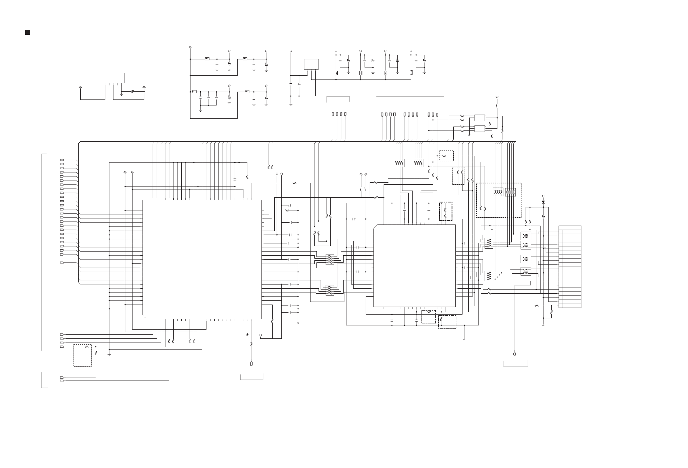
HDMI TX CIRCUIT DIAGRAM
5V_INPUT
MCLK
RX_VD23
RX_VD22
RX_VD21
RX_VD20
RX_VD19
RX_VD18
RX_VD17
RX_VD16
RX_VD15
RX_VD14
RX_VD13
RX_VD12
RX_VD11
RX_VD10
RX_VD09
RX_VD08
RX_VD07
RX_VD06
RX_VD05
RX_VD04
RX_VD03
RX_VD02
RX_VD01
RX_VD00
RX_VD_CLK
for
RX_VD10
RX_VD09
RX_VD08
RX_VD07
RX_VD06
RX_VD05
RX_VD_CLK
RX_VD04
RX_VD03
RX_VD02
RX_VD01
RX_VD00
R850
NC(10)
lip
sync
R851
33
I RX
MPEG
RX_VD23
RX_VD22
RX_VD21
RX_VD20
RX_VD19
RX_VD18
RX_VD17
RX_VD16
RX_VD15
RX_VD14
RX_VD13
RX_VD12
RX_VD11
RX_VD10
RX_VD09
RX_VD08
RX_VD07
RX_VD06
RX_VD05
RX_VD04
RX_VD03
RX_VD02
RX_VD01
RX_VD00
RX_VD_CLK
DE
HSYNC
VSYNC
HDMI_SPDIF
SPDIF_OUT
3.3V_HDMI
HH-221(2)
IC850
VC
VO
VIN
GND
NC
4
2
3
1
5
DGND
C852
DGND
TDVC18
3.3V_HDMI
47 / 16
TDVD33
76
CVCC18
77
D10
78
D9
79
D8
80
GND
81
GND
82
GND
83
GND
84
D7
85
D6
86
D5
87
GND
88
IDCK
89
IOVCC33
90
D4
91
D3
92
D2
93
D1
94
D0
95
GND
96
GND
97
GND
98
GND
99
CVCC18
100
GND
RX_VD11
75
1
D11
DE
RX_VD12
RX_VD13
74
73
D12
HSYNC
2
3
D13
VSYNC
RX_VD15
RX_VD14
72
71
D14
SPDIF
4
5
R852
70
GND
D15
SD3
MCLK
6
33
33
R853
L851
HH-221(2)
C856
C855
0.1uF
1000pF
DGND
RX_VD16
66
69
GND
SD2
7
64
68
65
67
63
IOVC33
GND
GND
GND
D16
CVCC18
IC851
Sil9034
CVCC18
SCK
WS
SD1
9
8
GND
SD0
12
11
10
13
33
33
R854
R855
L852
0.1uF
RX_VD17
RX_VD18
62
61
D17
IOVCC33
14
15
C853
C857
D18
DCLK
DGND
1000pF
RX_VD19
RX_VD20
59
60
D19
DR0
16
17
RDVD33
C854
10/16
TDVD33
C858
10/16
RX_VD21
58
D20
D21
DR1
DL0
18
DGND
DGND
RX_VD22
RX_VD23
56
57
D22
DL1
20
19
RDVD33
L853
HH-221(2)
C860
0.1uF
DGND
DGND
TAVD 33
L854
HH-221(2)
C862
0.1uF
DGND
DGND
10K
C859
R858
0.1uF
55
54
53
51
52
IOVCC33
TMODE
GND
D23
VPP18
HPD
50
CI2CA
49
CSDA
48
CSCL
47
DSDA
46
DSCL
45
DDCPWR5V
44
AVCC 33
43
AGND
42
PVCC2
41
AGND
40
TX2+
39
TX2-
38
AVCC 18
37
TX1+
36
TX1-
35
AGND
34
TX0+
33
TX0-
32
AVCC18
31
TXC+
30
TXC-
29
AGND
28
PVCC1
27
EXT_SWG
26
AGND
INT
DR2
DR3
DL2
DL3
21
RESET#
24
23
25
22
TAVC18
TW851
33
R862
C861
10/16
C863
10/16
MI_HDMI_DAT
MI_HDMI_CLK
33
33
R856
R857
TDVD33
R861
510
3.3V_HDMI
C864
C876
0.1uF
10/16
DGND
TAVC18
33
C866
10/16
R859
4.7K
0.1uF
C868
0.1uF
1000pF
C869
C867
0.1uF
C870
0.1uF
C872
1000pF
0.1uF
C871
C865
R860
DGND
IC852
LM1117_1.8V
V_OUT
V_IN
3
TX_SCL
ADJ/GND
2
XX
R865
1
TX_SDA
XX
R866
RDVC18
HH-221(2)
MICOM
MI_HDMI_DAT
MI_HDMI_DAT
XX
XX
R864
R863
2
1
4
3
6
5
8
7
R868
10(A)
2
1
4
3
6
5
8
7
R867
10(A)
C874
0.1uF
L855
DGND
TMDS_SW2
MI_HDMI_CLK
MI_HDMI_CLK
TMDS_SW2
TMDS_SW1
RAVC18
C875
10/16
TMDS_SW1
VCC50
C882
10/16
0.1uF
0.1uF
C886
C885
HH-221(2)
HH-221(2)
L858
C877
0.1uF
L856
TDVD33
L859
HH-221(2)
DGND
XX(4.7K)
XX(4.7K)
64
63
62
61
60
59
58
57
56
55
54
53
52
51
50
49
10/16
R878
R877
C878
HPD3
A24
B24
Vcc
A23
B23
GND
A22
B22
Vcc
A21
B21
SCL2
SAD2
HPD2
VDD
TDVC18
HH-221(2)
TXC-_MPEG
TXC-_MPEG
1
SDA3
A14
48
C879
0.1uF
L857
TXC+_MPEG
TX0-_MPEG
TXC+_MPEG
TX0-_MPEG
TX0+_MPEG
R869
10(A)
2
3
GND
SCL3
Vcc
B14
46
47
C880
10/16
DGND
TX0+_MPEG
TX0-_MPEG
TXC+_MPEG
TXC-_MPEG
3
1
7
5
4
2
8
6
4
5
A31
B31
A13
B13
45
44
C890
0.1uF
TAVC18
HH-221(2)
MPEG
TX1-_MPEG
TX1-_MPEG
TX1+_MPEG
TX0+_MPEG
0.1uF
C883
6
7
Vcc
B32
TMDS361
IC853
A12
GND
42
43
C887
0.1uF
L860
TX2-_MPEG
TX1+_MPEG
TX2+_MPEG
TX2-_MPEG
TX1+_MPEG
TX1-_MPEG
3
1
5
R870
10(A)
4
2
6
9
8
A32
GND
Vcc
B12
41
40
C891
C888
10/16
DGND
TX2+_MPEG
TX2+_MPEG
TX2-_MPEG
7
8
11
10
A33
B33
A11
B11
38
39
R875
10K
GPIO Mode
0.1uF
MP_HDMI_SCL
MP_HDMI_SDA
MP_HDMI_SDA
MP_HDMI_SCL
MP_HDMI_SDA
MP_HDMI_SCL
XX(33)
XX(33)
R871
R872
0.1uF
C889
13
12
14
Vcc
A34
B34
SCL1
SDA1
HPD1
35
36
37
HPLUG
TX_SDA
HDMI TX
ONLY OPTION
R891
NC(100)
I2C MODE
OPTION
1K
R873
HIGH- 10M CABLE
100
R880
3.9K
R879
16
15
GND
VSADJ
Y4
Z4
Vcc
Y3
Z3
GND
Y2
Z2
Vcc
Y1
Z1
GND
SCL_SINK
SDA_SINK
HPD_SINK
S1
S2
EQ
34
33
R89H
NC(10K)
I2C
Mode
OPTION
TX_SCL
R89A
R89C
R89D
R89E
MI_HDMI_DAT
NC(33)
R89J
17
18
19
20
21
22
23
24
25
26
27
28
29
30
31
32
33
33
33
33
DGND
TMDS_SW2
MI_HDMI_CLK
NC(33)
33
R89K
R881
C893
0.1uF
C892
0.1uF
DGND
IC855
NLASB3157DFT2G
SELECT
B1
1
GND
VCC
2
A
B0
3
IC856
NLASB3157DFT2G
SELECT
B1
1
GND
VCC
2
A
B0
3
TMDS_SW1
33
R882
XX(33)
R895
10(A)
10(A)
VCC50
L862
HH-221(2)
6
5
4
6
5
4
XX(33)
R896
R888
2
4
6
8
R887
2
4
6
8
XX
XX
R89F
33
R89G
33
TXC-_MPEG
1
3
5
7
1
3
5
7
R884
R883
TMDS_SW2
TX0+_MPEG
TXC+_MPEG
TX0-_MPEG
R893
10(A)
3
1
7
5
4
2
6
8
R899
33
TX2+_MPEG
TX1+_MPEG
TX2-_MPEG
TX1-_MPEG
HDMI TX ONLY OPTION
R894
10(A)
3
1
7
5
4
2
6
8
4.7K
R885
ACM2012H
F861
1
2
1
4
2
ACM2012H
F862
ACM2012H
F863
1
4
2
F864
ACM2012H
1
4
2
CEC_TX/RX
4
3
3
3
3
VCC50
4.7K
R886
R889
33
DGND
D851
SMAB34
10/16
C894
R890
CN850
TX2+
1
GND
2
TX2-
3
TX1+
4
GND
5
TX1-
6
TX0+
7
GND
8
TX0-
9
TXC+
10
GND
11
TXC-
12
CEC
13
RESERVE
14
SCL
15
SDA
16
GND
17
5V
18
HP_DET
19
47K
MICOM
HDMI_TX_RST
MICOM
2-8
Page 47

iPod CIRCUIT DIAGRAM
R3F7
3.3K
R3D0
47K
R3F5
3.3K
R3H8
47K
IC854
LM39102D-ADJ
OUT
ADJ
GND
4
3
5
5.6V_INPUT
IN
EN
2
1
+12V
L3C7
HH-221(2)
< I_POD CONNECTOR>
JK3C2
DGND
1
DGND
2
TPA+
3
USB D+
USB D-
USB Vbus
Accesory identify
Accesory power
Accesory Detrct
Compsite
Video
Remote sense
Line-IN L
Line-IN R
Line-OUT L
Line-OUT R
Return
Audio
Ipod_Det
TPA-
TPB+
TPB-
DGND
DGND
RX
TX
4
5
6
7
8
9
10
11
12
13
14
15
16
17
18
19
20
21
22
23
24
R_DGND
R_USB_D+
R_USB_D-
USB_VBUS
ACC_IDENTIFY
R_PWR
R_RX
R_TX
ACC_DETECT
R_CVBS
AUDIO_RTN
R_OUT_L
R_OUT_R
R_DET
ICDGND
R3C5
549K(1%)
C3C1
XX
2
1
Q3C4
2SK3018
2
1
Q3C3
2SK3018
3
R3F6
100K
3
R3G9
10K
R3H6
100K
C3E4
R3F0
10K
XX
ICDGND
C3E8
XX(104)
L3C1
HB-102(1)
HB-102(1)
HB-102(1)
C3E5
XX
L3C9
L3C5
R3E0
75K
HB-102(1)
C3E6
XX
L3C3
R3D1
75K
C3C9
104
R3H0
100K
C3E7
47/16
100K
R3H1
L3C6
HH-221(2)
R3G0
1K
C3C6
104
CF3C1
ACM2012H(TDK)
1
2
C3F1
105(2)
C3F4
105(2)
R3C0
10K
4
3
C3E3
24pF
C3C2
24pF
R3J1
1.8K
R3J0
560
C3F0
105(2)
C3E9
105(2)
ICDGND
NEW
NJM2794RB2
10
IN1+
9
IN1-
8
NC
7
IN2-
6
IN2+
4.7K
ITEM
IC3C3
R3H9
OUT1
GND
VREF
V+
OUT2
C3F3
47/16V
L3C8
HH-221(2)
ICDGND
L3D2
HB-102(1)
L3D3
HB-102(1)
C3F5
105(2)
C3D4
XX
R3H5
100(1)
L3D1
HB102(1)
R3H4
100
AGND
L3C2
HH-221(1)
C3F6
105(2)
1
2
C3F2
3
10/16V
4
5
AGND
DGND
P_CTRL
I_PHONE_CTL
IPOD_PWR
IPOD_RX
IPOD_TX
IPOD_VIDEO
IPOD_R
IPOD_L
IPOD_DET
TO MICOM
D_IPOD_R
IGND
D_IPOD_L
Close to ADC
2-9
Page 48

A
AMP CIRCUIT DIAGRAM
[ BOARD ]
CN602
VCC
VCC
VCC
VCC
PGND
PGND
PGND
DGND
DGND
DGND
P_CTL
12V
4
3
5
2
1
9
8
6
7
10
11
12
7V
P_SENSE
13
14
[ 2.1CH SPEALER OUT ]
SW-
FR-
SW+
FR+
FL+
FL-
JK704
1
2
6
4
5
3
[ 5.1CH SPEALER OUT ]
RL-
W+
RL+
FL+
FL-
JK703
4
5
3
1
2
RR-
FR-
RR+
FR+
C+
C-
W-
7
6
9
8
11
10
12
L718
PGND
HH-221(2)
104(2)
C706
104(2)
47UF/25V
C707
C705
10(3)
R702
10(3)
R703
C702
104
C708
103(2)
PGND
C701
104
PGND
C703
1000/50
C704
104(2)
44
1
R701
3.3(2)
C709
333(2)
43
GVDD_A
GVDD_B
2
100
R7A8
BST_A
OTW
3
42
TP701
NC
NC
SPK_FL+
R7C0
3.3(2)
104(2)
C710
224(2)
C711
331(2)
41
40
PVDD_A
NC
4
5
100
R704
103(2)
C712
R707
2.2(2)
C713
224(2)
4
1
R708
18(2)
PGND
C714
224(2)
39
PVDD_A
OUT_A
SD
PWM_A
6
100
R705
R709
C7G6
474(3)
L701
38
7
TP601
100
TP702
PGND
C7G7
103(2)
104(2)
R711
2.2(2)
C715
10uH
R712
18(2)
C716
224(2)
37
GND_B
GND_A
RESET_AB
PWM_B
8
TP602
100
R710
TP703
DGND
SPK_FL-
R7C1
3.3(2)
C717
C719
224(2)
C718
224(2)
3
2
C720
331(2)
333(2)
C721
34
35
36
PVDD_B
BST_B
OUT_B
IC701
TAS53X2(DDV)
AGND
GND
OC_ADJ
9
11
10
22K(27K)
R713
SPK_RL+
R7C2
3.3(2)
C725
224(2)
C726
331(2)
333(2)
C722
32
33
BST_C
VREG
13
12
104
C723
TP704
P_CTRL
103(2)
C727
104(2)
2.2(2)
C728
224(2)
4
1
18(2)
PGND
C730
224(2)
31
PVDD_C
M3
14
TP705
C7G8
R716
R717
OUT_C
M2
12V
L702
30
15
474(3)
10uH
P_SENSE
103(2)
R719
2.2(2)
C731
R720
18(2)
29
GND_C
M1
16
TP706
C7G9
104(2)
224(2)
C732
224(2)
GND_D
PWM_C
TP603
100
R718
R7C3
3.3(2)
C733
C735
224(2)
C734
3
2
C736
331(2)
27
28
OUT_D
RESET_CD
18
17
100
R722
SPK_RL-
26
PVDD_D
PVDD_D
NC
PWM_D
19
TP604
< WIRELESS OPTION >
SPK_FL+
SPK_FL-
SPK_RR+
SPK_RL+
SPK_RR-
SPK_RL-
SPK_FR+
SPK_FR-
SPK_WF+
R7C4
C7H0
3.3(2)
103(2)
C754
104(2)
R733
C752
2.2(2)
224(2)
333(2)
43
BST_A
OTW
2
100
R7B0
C755
224(2)
4
L706
1
R734
18(2)
C753
331(2)
C792
224(2)
41
42
3
NC
NC
PVDD_A
NC
4
40
PVDD_A
SD
5
100
R756
39
OUT_A
PWM_A
6
100
R757
R761
38
7
100
C767
C771
224(2)
224(2)
C769
BST_B
AGND
33
12
104
C765
C766
331(2)
333(2)
C764
32
BST_C
VREG
13
4
1
R743
18(2)
C768
224(2)
31
PVDD_C
OUT_C
M3
M2
14
L705
30
15
474(3)
10uH
GND_C
M1
R746
18(2)
224(2)
29
GND_D
PWM_C
16
100
R745
R735
3
2
PGND
C770
28
OUT_D
RESET_CD
17
TP605
100
331(2)
27
18
C772
PVDD_D
PWM_D
TP606
100
R748
26
PVDD_D
NC
19
R750
3.3(2)
25
20
NC
NC
C777
1000/50
C778
104(2)
24
BST_D
VDD
21
C774
R723
C779
103(2)
C773
333(2)
23
22
R752
PGND
R751
10(3)
C775
104(2)
GVDD_D
GVDD_C
C776
104(2)
10(3)
PGND
104(2)
[XX]
PGND
R753
3.3(2)
C781
1000/50
C782
104(2)
R754
10(3)
C783
104(2)
PGND
C784
104(2)
R755
10(3)
C780
C785
47UF/25V
104
C786
103(2)
PGND
44
1
C787
GVDD_A
GVDD_B
C750
R728
10(3)
C747
104(2)
PGND
C748
104(2)
R729
10(3)
C744
104
47UF/25V
C749
R727
3.3(2)
C746
104(2)
C751
44
GVDD_A
GVDD_B
1
103(2)
333(2)
43
2
100
R7A9
PGND
42
BST_A
OTW
3
PGND
C756
C758
224(2)
224(2)
41
38
40
39
PVDD_A
PVDD_A
OUT_A
NC
NC
SD
PWM_A
NC
4
7
5
6
100
R730
36
37
GND_B
GND_A
RESET_AB
PWM_B
9
8
333(2)
C763
34
35
PVDD_B
OUT_B
IC702
TAS53X2(DDV)
GND
OC_ADJ
11
10
22K
R739
R724
C743
103(2)
3.3(2)
C741
1000/50
C742
104(2)
PGND
R725
10(3)
C737
333(2)
C739
104(2)
25
23
24
PGND
BST_D
NC
GVDD_D
NC
VDD
GVDD_C
20
22
21
C740
104(2)
10(3)
R726
104(2)
C738
1(3)
R749
47UF/25V
C7G3
PGND
C7H1
103(2)
R737
2.2(2)
C757
474(3)
10uH
R738
18(2)
37
GND_A
RESET_AB
8
100
R762
R7C5
3.3(2)
C759
104(2)
C761
224(2)
C760
224(2)
3
2
C762
331(2)
PGND
C794
224(2)
36
35
PVDD_B
GND_B
OUT_B
TAS53X2(DDV)
GND
OC_ADJ
PWM_B
9
10
22K
R765
SPK_WF-
333(2)
C799
34
BST_B
IC703
AGND
11
SPK_CEN+
R7C6
3.3(2)
C790
104(2)
C788
224(2)
C791
224(2)
C789
331(2)
PGND
333(2)
C7A0
32
33
BST_C
PVDD_C
M3
VREG
13
12
104
C7A1
4
1
31
14
C7H2
103(2)
R759
2.2(2)
R760
18(2)
C7A2
224(2)
OUT_C
M2
L707
30
15
474(3)
10uH
103(2)
2.2(2)
C793
18(2)
GND_C
M1
C7H3
R763
R764
29
GND_D
PWM_C
16
100
R731
C795
104(2)
C796
224(2)
3
2
331(2)
C7A3
224(2)
28
OUT_D
RESET_CD
17
TP609
R7C7
3.3(2)
C797
224(2)
C798
27
PVDD_D
PWM_D
18
TP610
100
R736
SPK_CEN-
25
26
PVDD_D
NC
20
19
SPK_CEN+
R768
3.3(2)
24
BST_D
NC
NC
21
R767
SPK_CEN-
103(2)
C745
1000/50
C7A8
104(2)
10(3)
C7A4
333(2)
104(2)
23
GVDD_D
VDD
GVDD_C
22
104(2)
R770
C7A5
SPK_WF+
C7A9
PGND
R769
C7A6
C7A7
10(3)
104(2)
1(3)
SPK_WF-
PGND
PGND
R771
3.3(2)
C7B1
1000/50
C7B2
104(2)
R772
10(3)
C7B3
104(2)
PGND
C7B4
104(2)
C7B0
104
C7B5
47UF/25V
103(2)
R773
10(3)
C7B6
PGND
44
1
C7B7
333(2)
43
BST_A
GVDD_A
OTW
GVDD_B
2
100
R7B1
42
3
NC
NC
SPK_FR+
R7C8
3.3(2)
C7B8
224(2)
224(2)
C7B9
331(2)
PGND
41
40
PVDD_A
NC
4
5
100
R774
103(2)
C7C1
104(2)
2.2(2)
C7C0
4
1
18(2)
224(2)
39
PVDD_A
SD
6
100
C7H4
R777
R778
C7C2
OUT_A
PWM_A
TP611
R775
R779
103(2)
R781
2.2(2)
C7C3
474(3)
L703
10uH
R782
18(2)
38
37
GND_A
RESET_AB
7
8
100
C7H5
R7C9
3.3(2)
C7C5
104(2)
C7C7
224(2)
C7C6
224(2)
3
2
C7C8
331(2)
C7C4
224(2)
35
36
GND_B
OUT_B
TAS53X2(DDV)
OC_ADJ
PWM_B
9
10
TP612
22K(27K)
100
R783
R780
SPK_FR-
333(2)
C7C9
34
PVDD_B
IC704
GND
11
SPK_RR+
33
BST_B
AGND
12
104
C7D1
R7D0
3.3(2)
C7D2
224(2)
C7D3
331(2)
BST_C
VREG
104(2)
PGND
333(2)
C7D0
32
13
C7H6
103(2)
C7D4
2.2(2)
C7D5
224(2)
4
1
18(2)
C7D6
224(2)
31
PVDD_C
M3
14
R786
L709
R787
30
OUT_C
M2
15
C7D7
474(3)
10uH
GND_C
M1
103(2)
R789
2.2(2)
R790
18(2)
29
16
C7H7
104(2)
224(2)
GND_D
PWM_C
TP607
100
R788
3.3(2)
C7D9
224(2)
C7E0
224(2)
3
2
C7E2
331(2)
C7D8
28
OUT_D
RESET_CD
17
R7D1
C7E1
27
PVDD_D
PWM_D
18
TP608
100
R792
SPK_RR-
25
26
PVDD_D
NC
20
19
R794
3.3(2)
NC
NC
C7E7
1000/50
C7E8
104(2)
24
BST_D
VDD
21
C7E4
R793
103(2)
C7E3
23
C7E9
333(2)
GVDD_D
GVDD_C
22
R796
PGND
R795
10(3)
C7E5
104(2)
C7E6
104(2)
C7F9
10(3)
104(2)
[XX]
47U/25V
PGND
PGND
AMP_OTW
FL+
AMP_SD
FL-
AMP_PDN
R799
10K
FAN_CTL
KRC103S
C
Q703
KTA1504S
R7B5
100K(2)
C+
AMP_OTW
AMP_PDN
AMP_SD
AMP_PDN
P_CTRL
FAN_CTL
AMP_OTW
P_CTRL
FAN_CTL
P_SENSE
P_SENSE
AMP_SD
< MICOM SECTION >
RL-
RL+
R7B8
12V
Q701
C
B
E
PGND
R7A0
1K
NC
R7A2
Q702
KTA1504S
R7A1
NC
R7A3
E
47K
R7A7
47K
B
PGND
NC
R7A4
NC
NC
R7A6
R7A5
R7D6
470
C
R7D5
470
470
R7D4
470
R7D3
470
R7D2
104
C7F6
C7F7
10/16
PGND
TP707
TP708
FAN CONTROL OPTION
FAN DC(6.3V)
2
1
GND
CN603
FAN
1K(2)
104(2)
R7B6
1K(2)
100K(2)
C7G2
R7B7
C7G4
0.01UF
PGND
Q704
KTA1504S
Q705
KRC103S
C7G5
0.01UF
R7B9
10K(2)
WF-
WF+
R7B3
C7G1
1K(2)
104(2)
R7B4
1K(2)
5VA
FR-
FR+
RL+
FL-
RL-
FL+
FL-
RL-
FL+
RL+
RR-
RR+
C-
C+
WF+
WF-
C-
WF+
WF-
FR+
RR-
FR+
FR-
+
+
C+
FR-
FR
RR-
FR
< DSP SECTION >
MP_PROTECT
2-10
Page 49

DSP & PWM CIRCUIT DIAGRAM
<< DSP & PWM SECTION >>
VCC33
VCC18
R640
100
ON
L605
HH-221(2)
24.576MHZ
X602
R641
33pF
C626
DGND
VCC33
L606
HH-221(2)
C625
1M
C627
4.7K
4.7K
R644
10u/16
DGND
33pF
R643
TP625
C630
10u/16
DSP_BSY
DSP_IRQ
TP613
R638
C628
R639
104
C631
R658
5.1K_1%
R648
10_1%
STZ5.6N
C629
100
104
100
ZD600
104
R642
0 OHM
TP627
37
VDDI03
38
GPI08
39
DA_IRQ
40
GNDI04
41
/DA_BSY
42
VDD3
43
XTAL_OUT
44
XTI
45
XT0
46
GNDA
47
PLL_REF_RES
48
VDDA(3.3V)
PWM/DSP_CLK
PWM/DSP_DAT
TP628
100
100
R637
R636
34
32
31
33
35
36
GND4
GPI06
GPI07
GPI09
DA_SCL
DA_SDA
IC602
CS48560
DBDA
TEST
GND1
DAI1_LRCLK
DBCK
/RESET
4
6
2
5
3
1
100
47
4.7K
4.7K
R613
R611
R612
R647
TP626
104
C636
30
7
GNDI03
GNDI01
29
28
DA01_DATA3
DAI1_SCLK
8
9
47
R614
LRCK
RR+
RR-
FR+
FR-
C+
C-
WF+
WF-
RL+
RL-
FL+
FL-
BCK
MCLK
ADATA0
ADATA1
ADATA2
DSP_RST
PWM_RST
DSP_BSY
DSP_IRQ
PWM/DSP_CLK
PWM/DSP_DAT
SPEANA
DSP_DATA0
DSP_DATA1
SPK CH OPTION
Non-Wireless
71
70
59
58
MCLK
VCC33
10K
R624
DSP_DATA2
DSP_DATA1
DSP_DATA0
10K
10K
R625
100
R627
25
26
27
VDD2
GPI018
VDDIO2
DA01_DATA2
DA01_DATA1
DA0_SCLK
GND3
DA0_LRCLK
DA1_DATA0
GNDIO2
GPIO15
GPIO14
VDD1
GPI017
DAI1_03
DAI1_D2
GND2
DAI1_D0
VDDI01
DAI1_D1
11
12
10
100
100
104
C633
R616
R615
C635
R623
R620
TP615
R617
104
100
100
C634
104
TP616
100
24
23
22
21
20
19
18
17
16
15
14
13
DGND
R632
DGND
ADATA2
ADATA0
VCC33
C623
DGND
BCK
LRCK
DSP_DATA0
DSP_DATA1
DSP_DATA2
C618
L601
HH-221(2)
10u/16
104
C621
104
C622
220U/6.3V
TP622
R650
47
R649
R629
R630
R631
47
100
100
100
TP621
TP620
TP619
TP618
C620
10u/16
L602
HH-221(2)
HH-221(2)
C614
104
C652
200U/6.3V
C616
104
XX(3P)
C6Y9
C617
104
C603
104
C619
L603
C615
103
C6Y8
1
IO_VSS1
2
PLL_DVSS
3
PLL_DVDD
4
IO_VDD4
5
IO_VDD5
6
PLL_AVDD
7
10
11
12
13
14
15
16
17
18
19
20
21
22
23
24
25
8
9
PLL_AVSS
IO_VSS9
IO_VDD10
MBCK
MLRCK
DVDD13
DVDD14
MSDINO
MSDIN1
MSDIN2
MSDIN3
SBCK
SLRCK
IO_VSS21
IO_VSS22
SSDINO
SSDIN1
SSDIN2
IO_VSS7
104
104
ADATA1
BCK
ADATA0
ADATA1
ADATA2
R659
R661
R660
N.C
N.C
N.C
LRCK
DSP_RST
TP623
104
C602
100
99
SCAN_ENA
TEST_MODE3
SSDIN3
EXT_MUTE
28
27
26
100
R610
PWM_RST
100
R608
97
98
96
TEST_MODE1
TEST_MODE2
IO_VDD29
IO_VSS28
29
30
95
/RESET
IO_VSS95
MIC_BCK
MIC_MCLK
31
104
C613
TP617
3.3V
104
C654
94
IO_VDD94
MIC_LRCK
32
C611
93
92
DVSS92
DMIX_MCLK
MIC_SDIN
DVDD34
34
33
103
R656
120
12.288MHZ
104
22pF
C656
C650
TP614
90
89
91
DVDD91
DMIX_BCK
DMIX_SDOUT
IC601
PS9830
DVSS35
PWM_SWL_P
PWM_SWL_M
36
37
35
C610
R657
X601
TP624
88
87
CLK_OUT
DMIX_LRCK
IO_VDD39
IO_VSS38
39
38
104
1M
22pF
C657
86
85
CLK_IN
IO_VSS85
PWM_HP_R_P
PWM_HP_R_M
41
40
84
42
83
SPI/I2C
/CS/I2C_AD2
DVSS43
DVDD42
43
C609
C653
81
82
SI/I2C_ADD
IO_VSS44
45
44
104
R603
104
80
DVSS81
PWM_HP_L_M
46
PWM/DSP_CLK
PWM/DSP_DAT
100
100
R602
77
78
79
76
DVDD80
SO/SDA
SCK/SCL
EPD_ENA
OVERLOAD
PWM8_P
PWM8_M
IO_VSS73
IO_VDD72
PWM7_P
PWM7_M
IO_VSS69
PWM6_P
PWM6_M
DVDD66
IO_VDD65
IO_VSS64
DVSS63
PWM5_P
PWM5_M
IO_VSS60
PWM4_P
PWM4_M
IO_VSS57
IO_VDD56
PWM3_P
PWM3_M
IO_VSS53
PWM2_P
PWM2_M
IO_VDD47
PWM_HP_L_P
IO_VSS50
PWM1_P
PWM1_M
49
48
47
50
104
R670
C612
10K
R609
1.2K
75
74
73
72
71
70
69
68
67
66
65
64
63
62
61
60
59
58
57
56
55
54
53
52
R671
51
10K
DGND
C606
C607
C605
104
C608
104
104
104
FR+
FR-
RL+
RL
-
LRCK
MPEG
BCK
MCLK
ADATA0
ADATA1
ADATA2
MICOM
DSP_RST
PWM_RST
DSP_BSY
DSP_IRQ
PWM/DSP_CLK
PWM/DSP_DAT
SPEANA
WIRELESS
DSP_DATA0
DSP_DATA1
Wireless
RL+
RL-
FR+
FR
-
EXT_MUTE
C+
C-
WF+
FL-
FL+
RL-
RL+
WF-
FR-
FR+
RR-
RR+
DPS USE
NO DSP
R629
X
R659
R631
R630
0
0
0
X
X
R661
R660
X
X
X
0
0
0
FL-
FL+
RL-
RL+
WF-
WF+
C+
C-
FR-
FR+
RR-
RR+
R663
100K
< AMP SECTION >
PGND
C658
10u/16
D601
KDS160(FX)
R664
100K
C659
2.2(2)
R665
100K
C660
331
LEVEL METER OPTION
SPEANA
C661
331
R667
R666
10K
10K
R668
10K
R669
10K
2-11
Page 50

I/O JACK CIRCUIT DIAGRAM
VCC50
+12V
JK250
9
8
7
6
5
4
3
2
1
R278
R279
R280
R281
R269
R260
R270
R299
R291
R292
R293
R294
R284
R254
JK252
"A"
"B"
"C"
AGND
HB-102(1)
L271
HB-102(1)
L272
HB-102(1)
L273
HB-102(1)
L274
R271
10K
HB-102(1)
L275
HB-102(1)
L276
OPTION TABLE
WITH IPOD
WITH SCART
75 OHM
75 OHM
75 OHM
75 OHM
75 OHM
75 OHM
75 OHM
75 OHM
X
X
X
X
X
390 OHM
USED
USED
USED
X
W/O SCART
R273
10K
R272
10K
0 OHM
0 OHM
0 OHM
39 OHM
220 OHM
X
X
X
0 OHM
0 OHM
0 OHM
0 OHM
X
390 OHM
X
X
X
USED
VCC50
Q272
A1298Y
R274
4.7K
Q271
KTD1304S
C271
121
C272
121
R275
4.7K
KTD1304S
R276
4.7K
KTD1304S
R277
4.7K
KTD1304S
AGND
W/O IPOD
WITH SCART
75 OHM
75 OHM
75 OHM
75 OHM
75 OHM
75 OHM
75 OHM
75 OHM
X
X
X
X
0 OHM
X
USED
USED
USED
X
Q273
Q274
Q275
AGND
W/O SCART
0 OHM
0 OHM
0 OHM
0 OHM
0 OHM
0 OHM
0 OHM
0 OHM
0 OHM
USED
SCART/RCA
75/39/0
R281
75/0
R279
75/0
R280
75/0
R278
WITH SCART
" A "
WITH SCART
" C "
X
X
X
X
X
X
X
X
CVBS_OUT
Y/G_OUT
PR/R_OUT
PB/B_OUT
RGB_VIDEO
AUX_L
AUX_R
JK251
IPOD_VIDEO
IPOD_VIDEO_MUX
CVBS_MM1692
CVBS
Y/G
PB/B
PR/R
S_AUX_R
121
C273
L277
HB-102(1)
1
3
2
N.C
AUDIO_IN_R
N.C
4.7K
R282
4
GND
C274
S_AUX_L
121
L278
5
GND
C275
10/16
C299
33pF
C276
10/16
PB/B_OUT
R283
HB-102(1)
6
AUDIO_IN_L
WITH IPOD
IC255
MM1507
6
IN1
5
GND
OUT
IN2
4
AGND
R284
VCC
0(XX)
W/O IPOD
4810S-0115A
Connect to 9,13 GND Pin
W/O SCART
75
AGND
AGND
JK252
2
1
L279
HB-102(1)
7
8
9
11
10
GND
N.C
GREEN
BLUE
SCART_CTL
SW
12
N.C
1
2
3
Y/G_OUT
R285
75
L280
13
GND
L282
HH-221
C277
R286
HB-102(1)
14
GND
C278
104
100u/16V
AGND
VCC50
PR/R_OUT
75
L281
HB-102(1)
16
15
RED
R/G/B SELECT
L283
17
GND
C280
C279
C281
C282
C283
L284
18
GND
C286
HH-221
0.1uF
1U
1U
1U
1U
CVBS_OUT
R287
HB-102(1)
19
V OUT
C284
47U/16V
AGND
AGND
75
20
V IN
470/6.3
C287
0.1uF
C285
22/16
WITH SCART
1
VCC
2
CIN
3
BIAS
4
Y1IN
5
MUTE
6
CYIN
7
GND1
8
CbIN
VCC50
Q276
KTD1304S
R288
75
D271
KDS160
AGND
21
RGB SELECT INPUT LEVEL
Low:0
0.4V
High:1.0
GND
IC250
MM1692XVBE
W/O SCART
RGB_VIDEO
R289
Q277
AGND
3.0V
" B "
COUT
CVBSOUT
YOUT
CYOUT
CbOUT
CrOUT
GND2
CrIN
R291
R292
R293
R294
1K
KRC103S
R290
820
0(XX)
0(XX)
0(XX)
0(XX)
R295
100K
16
15
14
13
12
11
10
9
AGND
KTD1304S (XX)
KTD1304S (XX)
D272
KTA1504
KDS160
R296
2.2K
Q279
Q279
AGND
AGND
Q278
R298
1K (XX)
C288
C289
C290
+12V
Q280
KRC103S
R297
2.2K
470/6.3
470/6.3
470/6.3
CVBS_OUT
CVBS_MM1692
Y/G_OUT
PB/B_OUT
PR/R_OUT
TV_MODE
16:9/4:3
V_MUTE
V_MUTE
16:9/4:3
TV_MODE
RGB_VIDEO
AUX_L
AUX_R
S_AUX_R
V_MUTE
S_AUX_L
IPOD_VIDEO_MUX
IPOD_VIDEO
CVBS
PR/R
PB/B
Y/G
75
R269
WITH SCART
AGND
R264
4.7K
R263
4.7K
R261
4.7K
R268
4.7K
75
75
R260
R270
Q281
KTD1304S
Q284
KTD1304S
Q282
KTD1304S
Q286
KTD1304S
75
R299
AGND
R259
+12V
VCC50
16:9/4:3
TV_MODE
RGB_VIDEO
S_AUX_R
S_AUX_L
IPOD_VIDEO_MUX
IPOD_VIDEO
100
AGND
L289
L290
220nH
470nH
C298
C297
33P
82P
C296
82p
C293
82P
C292
470p
L291
470nH
C295
33P
L285
470nH
C294
33P
L287
2.2nH
C291
470P
AGND
AGND
AGND
AGND
Q285
KTA1504
L286
220nH
L288
220nH
PR/R
12V
VCC50
PB/B
Y/G
CVBS
AUX_L
AUX_R
GND
V_MUTE
+12V
KTD1304S
R262
Q283
6630R-FB11T
CN250
1
PR/R
2
12V
3
VCC50
4
PB/B
5
GND
Y/G
6
GND
7
CVBS
8
9
16:9/4:3
10
TV_MODE
11
RBG_VIDEO
12
AUX_L
GND
13
14
AUX_R
15
GND
16
S_AUX_R
17
COMPOSITE_MUTE
18
S_AUX_L
19
IPOD_VIDEO_MUX
20
IPOD_VIDEO
R266
R267
10K
10K
4.7K
R265
10K
AGND
2-12
Page 51

MIC & USB & PTB CIRCUIT DIAGRAM
JK2D3
USB JACK
1
2
3
4
5
6
2
56K
R2G3
C2D1
220U/6.3V
C2G4
AGND
L2D3
AGND
6.8nF
HB
4.7/50
C2G3
C2D3
6.8nF
AGND
EAG35130501
JK2D4
JK2D1
DGND
1
3
6
5
4
2
3
7
8
9
1
AGND
4.7/50
C2G1
6.8nF
C2G5
C2D4
XX
R2G1
100K
R2G5
22K
L2D8
C2G6
AGND
ZD2M3
BZX84-C5V1
HB
L2D9
HB
XX
VCC50
D+
D-
PT_R
PT_L
MIC_DET
MIC
C2D6
C2D5
ZD2M2
STZ5.6N
104
104
C2D7
MIC_DET
D-
D+
PT_L
PT_R
104
ZD2EM1
BZX84-C5V1
MIC
PGND
VCC50
DGND
AGND
C2G8
24p
6630R-FB05M
CN202
1
MIC
PGND
2
MIC_DET
3
5V
4
5V
5
5V
6
5V
7
D-
8
9
DGND
D+
10
PTB_L
11
AGND
12
PTB_R
13
JK2D2
PGND
6
5
4
2
3
7
8
9
1
56K
R2G4
L2D5
HB
PGND
C2G2
6.8nF
R2G2
100K
R2G6
22K
DGND
AGND
L2D1
HB
AGND_1
PGND
PGND_1
2-13
Page 52

FRONT JACK CIRCUIT DAIAGRAM
TIMER PART
NC
TOUCH_CLK
6315_CLK
TOUCH_RST
6315_RX
TOUCH_DAT
6315_STB
5.6VA
5.6VA
REMOCON
5V
NC
KEY
NC
STBY_LED
DGND
5V_USB
VKK
FL(+)
FL(-)
CN302
DIS301
FL DISPLAY
10G
F+
1
2
100K
R331
C301
104
6315_CLK
6315_RX
6315_STB
5.6VA
RCU_IN
5V
KEY
STBY_LED
5V_USB
FL+(V1)
DGND
20
19
18
17
16
15
14
13
12
11
10
9
8
7
6
5
4
3
2
1
DGND
TOUCH_CLK
TOUCH_RST
TOUCH_DAT
C312
470uF/10V
5
GD10
P16
6
SEG16
10G
F+
P15
7
SEG15
9G
P13
8G
P12
P14
11
9
SEG14
10
GD9
SEG13
Q304
KRA103M
DGND
B
12
SEG12
Q303
C3205
R330
13
GD8
C
E
5V
8
7G
7G
6G
P11
P10
P9
15
SEG10
17
16
GD7
C307
L301
HH-221(2)
18
SEG9
14
SEG11
33K
19
GD6
47/16
20
SEG8
FL+(V1)
P8
R376
Q305
P7
21
SEG7
FL-(V2)
22
GD5
5G
4G
3G
P6
24
SEG6
P5
25
SEG5
ZD302
5.1V
GD4
26
R377
P4
27
SEG4
28
SEG3
P3
29
GD3
5G
23
3G
P2
30
31
SEG2
6315_STB
6315_CLK
2G
32
33
GD2
6315_RX
2G
P1
34
SEG1
R337
R362_1K
R363_1K
R364_1K
TP317
1G
1G
35
36
GD1
39
F-
F-
40
R332
FL-(V2)
C302
104
100K
DGND
GD1
TP319
GD2
TP320
GD3
TP321
GD4
TP322
GD5
TP323
GD6
TP324
KEY
GD7
TP325
R381
GD8
TP326
R382 R383 R384 R385 R386
SW302 SW303 SW304 SW305 SW306 SW307
GD10
GD9
TP327
TOUCH_CLK
TOUCH_DAT
TOUCH_RST
5V_VSB
TO TOUCH
CN303
DGND
1
TOUCH_CLK
2
3
TOUCH_DAT
TOUCH_RST
4
5V_USB
5
DGND
6
TO PWR KEY
C331
0.1uF
GR5
SG5
37
GR6
19
TP333
SEG6
SG6
36
GR7
20
TP334
SEG7
35
GR8
SG7
21
TP335
SEG8
34
GR9
GR10
GR11
SG17/GR12
VEE
SG16/GR16
SG15
SG14
SG13
SG12
SG11
SG10
SG9
SG8
22
TP336
SEG9
R351
33
100K
32
C3A2
47uF/50V
31
30
29
28
27
26
25
TP342
24
23
SEG10
C303
TP338
TP340
TP343
SEG11
TP339
TP341
104
SEG12
SEG13
DGND
TP337
SEG14
SEG15
SEG16
38KHz(6712R1238GA)
C304
47pF
40
42
41
44
43
VSS
VOL_LED1
VOL_LED2
VOL_LED3
LED4
OSC
DOUT
DIN
CLK
STB
K1
K2
47/10
12
C308
VSS
VDD
VDD
13
0.1uF
1
2
3
4
22K
5
6
7
8
9
10
11
TP318
C3A1
GS2
GR3
GS1
IC301
ET16315
SG3
SG1
SG2
16
14
15
17
TP328
TP329
TP330
SEG3
SEG1
SEG2
39
GR4
TP331
SEG4
38
SG4
18
TP332
SEG5
RC01
OUT
2
1
RL104R
VCC
3
100
R341
D301
GND
C309
220/6.3
STBY_LED
KEY
C313
DGND
104
C310
C314
xx(0.1uF)
DGND
xx(0.1Uf)
DGND
1
2
3
PN331
ST_BY
PWR_KEY
GND
KEY PART
CN301
ST-BY
PWR-KEY
GND
5.6VA
RCU_IN
LD304
R366
LED4
10K
10K
R339
R367
10K
R340
10K
VOL_LED3
LD301
R378 R379 R380
VOL_LED2
LD302 LD303
POWER
SW301
DGND
1
2
1
3
2
DGND
R399
LD314
R396
LD313
R395
LD312
R394
LD311
R393
LD310
R392
LD309
R391
LD308
R390
LD307
R389
R388
LD306
LD305
R387
LD304
2-14
Page 53

CIRCUIT VOLTAGE CHART
ICs on BOARD
MAIN
IC100 (EEPROM)
Pin No. SPEC DVD PB (V)
8 5 4.94
IC101 (A-Micom)
Pin No. SPEC VOLT
14 4.945.0
40
55
89
IC104
Pin No. SPEC VOLT
1 5.0 5.0
3 3.3 3.3
IC105
Pin No. SPEC DVD PB (V)
5 3.3 3.23
IC106
Pin No. SPEC VOLT
1 5.6 5.6
255
IC201 (ADC)
Pin No. SPEC VOLT
5 3.3 3.24
14 5 5.05
36 3.3 3.26
46 3.3 3.24
IC202 (DIR)
Pin No. SPEC DVD PB (V)
3 3.3 3.24
19 3.3 3.24
22 3.3 3.24
IC203 (SW)
Pin No. SPEC DVD PB (V)
5 3.3 3.22
IC204 (DIR)
Pin No. SPEC DVD PB (V)
3 3.3 3.22
19 3.3 3.22
22 3.3 3.22
IC250 (SCART)
Pin No. SPEC VOLT
1 5.06
5.0
4.945.0
4.945.0
4.945.0
5.065 5.0
IC255 (IPOD)
Pin No. SPEC VOLT
6 5.0
IC2A1 (MIC)
Pin No. SPEC VOLT
6 12.0
IC400 (MOTOR)
Pin No. SPEC VOLT
8 5.0
5.019 5.05
IC501 (MPEG)
Pin No. SPEC DVD PB (V)
1 1.8 1.88
2 3.3 3.22
12 3.3 3.22
22 3.3 3.22
25 1.8 1.88
38 3.3 3.24
57 3.3 3.24
67 3.3 3.24
79 1.8 1.87
92 3.3 3.24
101 3.3 3.24
109 1.8 1.87
114 3.3 3.24
119 1.8 1.87
125 3.3 1.88
134 3.3 3.22
139 3.3 3.22
141 3.3 3.22
150 3.3 3.22
151 3.3 3.22
163 3.3 3.22
164 3.3 3.22
165 1.8 1.88
IC502 (FLASH)
Pin No. SPEC DVD PB (V)
8 3.3 3.22
IC503 (SDRAM)
Pin No. SPEC DVD PB (V)
1 3.3 3.22
3 3.3 3.25
9 3.3 3.24
14 3.3 3.25
5.06
11.4
5.05
Pin No. SPEC DVD PB (V)
27 3.3 3.24
43 3.3 3.24
49 3.3 3.24
IC504 (EEPROM)
Pin No. SPEC DVD PB (V)
8 3.3 3.24
IC542
Pin No. SPEC DVD PB (V)
8 3.3 3.25
IC601 (PWM)
Pin No. SPEC DVD PB (V)
4 3.3 3.21
10 3.3 3.21
22 3.3 3.21
29 3.3 3.21
39 3.3 3.21
47 3.3 3.21
56 3.3 3.21
65 3.3 3.21
72 3.3 3.21
91 3.3 3.21
94 3.3 3.21
IC701 (AMP)
Pin No. SPEC DVD PB (V)
26 35 35.44
27 35 35.43
32 35 35.43
35 35 35.44
40 35 35.43
41 35 35.43
IC702 (AMP)
Pin No. SPEC DVD PB (V)
26 35 35.44
27 35 35.43
32 35 35.43
35 35 35.44
40 35 35.43
41 35 35.43
IC703 (AMP)
Pin No. SPEC DVD PB (V)
26 35 35.44
27 35 35.43
32 35 35.43
35 35 35.44
40 35 35.43
41 35 35.43
IC704 (AMP)
Pin No. SPEC DVD PB (V)
26 35 35.44
27 35 35.43
32 35 35.43
35 35 35.44
40 35 35.43
41 35 35.43
IC801 (EEPROM)
Pin No. SPEC DVD PB (V)
8 5 4.93
IC803 (HDMI Rx)
Pin No. SPEC DVD PB (V)
5 3.3 3.31
16 3.3 3.31
22 1.8 1.77
23 1.8 1.77
26 1.8 1.78
35 1.8 1.77
37 3.3 3.31
38 1.8 1.78
42 3.3 3.31
46 3.3 3.3
50 3.3 3.3
55 3.3 3.3
57 3.3 3.3
61 3.3 3.3
65 3.3 3.3
69 3.3 3.3
74 1.8 1.77
76 1.8 1.77
79 1.8 1.77
89 3.3 3.3
92 1.8 1.77
94 1.8 1.77
98 1.8 1.77
99 3.3 3.3
105 1.8 1.77
109 1.8 1.77
114 1.8 1.77
122 3.3 3.3
128 1.8 1.77
134 3.3 3.3
139 1.8 1.77
IC850
Pin No. SPEC VOLT
1 5.0
3 3.3 3.29
IC851 (HDMI SW)
Pin No. SPEC DVD PB (V)
12 1.8 1.77
14 3.3 3.3
28 1.8 1.77
32 1.8 1.77
38 1.8 1.77
42 1.8 1.77
44 3.3 3.3
45 5 5.06
53 3.3 3.3
55 1.8 1.77
64 1.8 1.77
66 3.3 3.3
76 1.8 1.77
89 3.3 3.29
99 1.8 1.77
IC852
Pin No. SPEC VOLT
2 1.8 1.77
3 3.3 3.3
IC853
Pin No. SPEC DVD PB (V)
6 3.3 3.3
12 3.3 3.3
19 3.3 3.3
25 3.3 3.3
40 3.3 3.3
46 3.3 3.3
49 3.3 3.3
55 3.3 3.3
61 3.3 3.3
FRONT
IC301 (VFD)
Pin No. SPEC VOLT
13 5.0
43 5.0
4.99
5.08
4.99
2-15
Page 54

CAPACITORs on BOARD
No Value (uF) Voltage_Spec positive (+) negative (-) voltage
C101 10uF 16 4.94 4.94
C106 100uF 16 5.00 5.00
C116 47uF 16 4.95 4.95
C117 10uF 16 3.90 3.90
C120 47uF 16 4.95 4.95
C123 100uF 16 3.30 3.30
C133 100uF 16 5.04 5.04
C201 10uF 16 2.50 0.34
C202 10uF 16 2.51 0.27
C203 10uF 16 2.50 0.28
C204 10uF 16 2.10 0.00
C205 10uF 16 2.51 0.28
C206 10uF 16 2.50 0.28
C207 10uF 16 2.51 0.27
C208 10uF 16 2.51 0.32
C211 10uF 16 2.41 2.41
C212 47uF 16 4.83 4.83
C213 10uF 16 5.05 5.05
C214 10uF 16 0.52 0.01
C215 10uF 16 0.52 0.10
C223 10uF 16 3.24 3.24
C224 10uF 16 3.24 3.24
C228 10uF 16 2.47 2.47
C229 10uF 16 3.24 3.24
C275 10uF 16 2.99 0.36
C276 10uF 16 2.38 0.17
C278 100uF 16 5.04 5.04
C284 47uF 16 5.03 5.03
C285 22uF 16 2.51 2.51
C286 470uF 6.30 1.44 0.97
C288 470uF 6.30 1.70 1.70
C289 470uF 6.30 2.34 2.34
C290 470uF 6.30 2.34 2.34
C2A3 22uF 16 1.95 1.95
C2A5 100uF 16 1.99 1.15
C2A7 1uF 50 0.00 0.00
C2A9 100uF 16 11.07 11.07
C2C2 10uF 16 3.25 3.25
C2C4 10uF 16 3.22 3.22
C2C6 10uF 16 2.48 2.48
C3D2 47uF 16 4.95 4.95
C417 47uF 6.30 3.19 0.92
2.41
0.00
0.00
0.00
0.00
0.00
0.00
0.00
2.16
2.24
2.22
2.10
2.23
2.22
2.24
2.19
0.00
0.00
0.00
0.00
0.42
0.00
0.00
0.00
0.00
2.63
2.21
0.00
0.00
0.00
0.00
0.00
0.00
0.00
0.84
0.00
0.00
0.00
0.00
0.00
0.00
0.84
No Value (uF) Voltage_Spec positive (+) negative (-) voltage
C418 47uF 6.30 3.19 0.15
C419 100uF 6.30 3.19 3.19
C420 100uF 6.30 5.03 5.03
C421 100uF 6.30 5.03 5.03
C422 100uF 6.30 1.89 1.89
C423 100uF 6.30 5.04 5.04
C426 47uF 16 2.05 2.05
C427 47uF 16 1.43 1.43
C553 10uF 25 1.31 0.27
C554 10uF 25 1.29 0.23
C555 47uF 16 3.24 3.24
C556 47uF 6.30 1.88 1.88
C557 47uF 6.30 1.88 1.88
C558 47uF 16 3.22 3.22
C559 47uF 6.30 1.87 1.87
C560 47uF 6.30 1.57 1.57
C561 47uF 6.30 1.36 1.36
C563 10uF 25 3.21 3.21
C564 10uF 25 3.25 3.25
C565 10uF 25 3.25 3.25
C618 10uF 16 1.92 1.92
C620 10uF 16 1.93 1.93
C622 220uF 6.30 3.21 3.21
C625 10uF 16 1.85 1.85
C630 10uF 16 3.22 3.22
C652 220uF 6.30 1.93 1.93
C707 47uF 25 11.79 11.79
C749 47uF 25 11.79 11.79
C785 47uF 25 11.79 11.79
C7B5 47uF 25 11.78 11.78
C7F7 10uF 16 11.77 11.77
C7F9 47uF 25 11.76 11.76
C7G3 47uF 25 11.77 11.77
C801 10uF 25 4.94 4.94
C852 47uF 16 3.31 3.31
C854 10uF 25 3.31 3.31
C858 10uF 25 3.31 3.31
C861 10uF 25 3.31 3.31
C863 10uF 25 3.31 3.31
C866 10uF 25 1.87 1.87
C875 10uF 25 1.78 1.78
C876 10uF 25 3.31 3.31
3.04
0.00
0.00
0.00
0.00
0.00
0.00
0.00
1.04
1.06
0.00
0.00
0.00
0.00
0.00
0.00
0.00
0.00
0.00
0.00
0.00
0.00
0.00
0.00
0.00
0.00
0.00
0.00
0.00
0.00
0.00
0.00
0.00
0.00
0.00
0.00
0.00
0.00
0.00
0.00
0.00
0.00
No Value (uF) Voltage_Spec positive (+) negative (-) voltage
C878 10uF 25 1.78 1.78
C880 10uF 25 1.78 1.78
C882 10uF 25 3.31 3.31
C888 10uF 25 1.78 1.78
C894 10uF 25 5.03 5.03
C130 10uF 16 3.23 3.23
C3A2 47uF 50 -27.60 27.6V
C307 47uF 16 -24.56 2.96V
C3A1 47uF 16 0.00 5V
C309 220uF 6.3 0.00 4.91V
C2D1 220uF 6.3 0.00 5.03V
C2D3 4.7uF 50 1.33 0.29V
C2D4 4.7uF 50 1.01 0.55V
0.00
-21.60
5.00
4.91
5.03
1.62
1.56
0.00
0.00
0.00
0.00
0.00
0.00
DIODEs on BOARD
ZD2M1 (BZX84-C5V1)
Pin No. VOLT
1 -0.01 V
2 -0.28 V
3 0.02 V
ZD2M2 (BZX84-C5V1)
Pin No. VOLT
1 -0.01 V
2 -0.13 V
3 -0.01 V
ZD302 (BZX84-C5V1)
Pin No. VOLT
10 V
2 0 V
3 5.07 V
ZD500 (BZX84-C5V1)
Pin No. VOLT
1 -0.01 V
2 -0.23 V
3 0 V
D801 (DAN202K)
Pin No. VOLT
1 -0.01 V
2 -0.23 V
30 V
2-16
Page 55

Printed circuit boards
Main board (forward side)
( Lead free solder used in the board (material : Sn-Ag-Cu, melting point : 219 Centigrade) )
18. 5V
5. GND
C865
L851
6. TX1-
10. TXC+
12. TXC-
16. SDA
13. CEC
C858
17. GND
14. RESERVE
15. SCL
19. HP DET
L857
L860
C866
C556
L503
C513
R449
C400
R451
R446
Q412
IC501
C402
IC851
C880
C876
C864
C573
C531
R527
Q503
C512
C511
C536
C510
R541
R542
R543
R450
C407
R432
R411
C416
C405
C422
IC106
R1E3
8. GND
11. GND
7. TX0+
9. TX0-
C888
R864
R861
L854
C427
C428
R416
IC400
D405
F501
2. GND
1. RX2+
C421
L405
R506
4. RX1+
5. GND
3. RX2-
R89K
R855
R525
R531
C420
6. RX1-
7. RX0+
R854
IC852
R532
R853
R518
10. RXC+
8. GND
9. RX0-
R851
R850
R852
C533
C570
11. GND
C875
C555
C509
C508
ZD500
12. RXC-
13. CEC
R89J
C565
R523
C563
C525
IC502
14. RESERVE
C507
16. SDA
17. GND
15. SCL
L856
C566
C551
18. 5V
19. HP DET
C527
C878
R830
R507
R504
R520
R514
R516
R515
C572
L855
R831
L507
R519
L853
C877
R832
C522
R517
R503
R512
R540
R509
C820
C821
C539
C528
C529
ZD501
L506
C861
R825
C829
R838
L502
R508
C526
R511
R526
C535
C541
R530
R814 R813
R836
R837
IC850
C564
C559
C542
IC504
R197
JK3C2
24. IPOD DEET
23. AUDIO RETURN
22. LINE OUT R
21. LINE OUT L
20. LIN IN R
19. LIN IN L
18. REMOTE SENSE
17. COMPOSITE VIDEO
16. ACCERRORY DETECT
15. TX
14. RX
13 DGND
12. DGND
11. ACCESSORY POWR
10. ACCESSORY IDENTITY
9. TPB-
8. USB VOUS
7. TPB+
6. USB D-
5. TPA -
4. USB D+
3. TPA+
2. DGND
1. DGND
CN501
3.3V
CN501
CN801
R835
CN105
RXD
TXD
IC803
C104
L104
C117
1.DEBUG2
2.DEBUG1
3.DEBUG0
4.RESET
GND
R834
R167
5.GND
R801
R826
R827
C824
C825
C828
C853
C834
C835
C854
R833
L852
C852
C123
IC104
R171
C109
IC100
R1C6
R173
IC101
R118
R117
R119
R126
R157
R156
R154
R103
R104
R195
R196
CN105
F861
CN402
23.CD VR
22.MON/MPD
21.CD LD
20.GND
19.SW PDIC
18.F( - )
17.T( - )
16.T( + )
15.F( + )
14.B
13.C
12.D
11.A
10.E
9.F
8.VCC
7.VREF/VC
6.GND
5.DVD VR
4.MON(COM)/5V
3.DVD LD
2.RF
1.NC/FHM-VCC
CN402
C408
L402
L400
C423
C417
R528
R250
R2A4
C238
C2A7
R2A5
C2A9
D851
4. TX1+
2. GND
1. TX2+
3. TX2-
CN850
R885
R886
C882
R408
C2E9
4. VCC50
5. VCC50
R875
C892
C891
C558
C561
C560
C557
C133
6. VCC50
7. VCC50
C889
C890
L505
8. USB N
9. DGND
L859
C886
C885
C543
10. USB P
11. PTB L
C894
L862
L858
C883
R877
R878
R891
R873
C540
C520
C537
R529
C547
C546
12. AGND
13. PTB R
R89D
R89A
R863
R865
R866
R860
R867
R868
R859
C863
C532
C538
C500
C401
R448
L403
CN103
CN850
R889
C237
IC2A1
C2A8
R893
C2A4
R2A3
R2A6
R890
R896
R895
R899
R89H
R882
R881
C893
R879
R880
C412
Q410
R428
Q406
R405
R404
Q411
C426
C418
R2A2
C2A3
C2A2
R2A1
C2A1
2. AGND
CN103
3. MIC DET
1. MIC INPUT
F862
F863
F864
R894
L401
C419
C554
C553
R521
C2A6
R556
JK201
Q801
R803
IC804
R811
R817
R236
C234
C232
C229
C233
L204
R1C7
R1C8
R184
R106
R198
C235
R809
L205
R805
IC805
R821
R819
C801
R235
C230
C231
C224
R183
R190
R1A7
L2C1
R1G6
R123
C2C2
C223
C228
C225
R191
R111
R105
C106
L203
C226
CN201
C227
20. IPOD VIDEO
19. IPOD VIDEO MUX
18. S AUX L
17.COMPOSITE MUTE
16. S AUX R
15. AGND
14. AUX R
13. AGND
12. AUX L
11. RGB VIDEO
10. TV MODE
9. 16:9/4:3
8. CVBS
7. AGND
6. Y/G
5. AGND
4. PB/B
3. 5V
2. 12V
1. PR/R
CN401
LM+
CLOSE
LM-
OPEN
IC102
R1A8
R112
R1A9
R2C4
R2C5
R2C6
R2C9
CN204
R2C7
GND
R1B4
R1B5
R151
R149
TU100
C201
C202
C214 C215
R228
CN401
R229
1. 5V
C2C6
C2C7
2. 5V
R1C5
R1C4
R1C2
4.RESET
3. GND
R220
R239
R240
C3F2
C3D4
R1C3
R1C1
R1B9
X100
9.8304MHz
D101
6.GND
5. MCLK
C209
C210
R222
R3H5
IC3C3
D400
C130
C101
8.RLCK
7. BCK
R224
R223
C212
C216
C268
R217
R221
C204
R3H4
C3F1
C3E3
R3H1
C3F4
R453
C3C2
R444
C403
R407
L106
Q101
R127
29. IGND
27 D IPOD L
30. IPOD VIDEO
28. IPOD DET
CN102
L102
10.SCL
9. DATA
11. SDA
R219
R2E8
C205
C206
L3D1
C3F6
C3F5
L3C2
C3F3
FM+
SP+
FM-
SP-
R457
R1C0
R174
C131
R172
C132
R170
IC105
R163
R160
R164
R162
C113
R146
R142
C111
R137
R131
R130
C120
C116
C2C4
C2C5
CN204
CN201
C213
R3H0
L3C3
25 D IPOD R
26. AGND
24. AGND
R116
R1A1
C102
C203
L3C5
23. IPOD PWR
22. IPOD TX
C134
R3J1
JK3C2
C3C1
R557
R3H9
C107
C103
L103
L201
C211
L3C1
L3C9
PN106
R1H2
R1H1
21. IPOD RX
19. TOUCH CLK/DGND
17. TOUCH RST/DGND
15. TOUCH DATA/DGND
13. 5.6VA
20. DGND/I PHONE CTL
18. 6315 CLK
16. 6315 RX
14. 6315 STB
12. 5.6VA
C1E
C1C
R1G5
C1B
R1G4
R1G3
R1G2
R1G1
L3D3
C3E5
CN602
15. MGND
14. MOTOR 5V
13. 5V
12. 5 . 6VA
11. 5 . 6VA
10. DGND
9. DGND
8. 3 . 8V
7. 3 . 8V
6. 3 . 8V
5. + 12V
4. AGND
3. F ( - )
2. F ( + )
1. VKK
11. REMOCON
9. DGND/VOL UP
7. DGND/VOL DN
10. VCC50 F
8. KEY
6. STBY LED
C1F
C1D
CN102
C3E6
CF3C1
L3C8
5. DGND
3. VKK
4. N.C
R3C0
L3D2
C3C9
1. ( - )
2. F ( + )
R3G0
R707
C3E7
L3C6
C708
C704
R701
CN602
1. VCC
2. VCC
3. VCC
4. VCC
5. PGND
6. PGND
7. PGND
8. DGND
9. DGND
10. DGND
11. P CTL
12. 12V
13. P SENSE
14. 7V
C702
JK251
R288
Q276
R3C5
C710
R558
R3E0
R3D1
C715
C713
L3C7
L701
JK704
JK703
R711
2.1CH
5.1CH
R7C0
L702
C7G6
C718
C719
C734
C735
R7C1
C712
C717
R719
C7G8
C731
R7C2
C728
C7G7
C725
R7C4
C733
R7G9
C727
R716
R7C3
R733
C769
C752
C767
L706
C771
R7C5
C795
R7C7
C7H3
C796
C7H4
C7C0
C7B8
C7C3
R7C8
R7C9C7C5
C7C1
C7H5
C7D4
R786
R777
C7C6
C7D2
C7D5
R781
C7C7
R7D0
C7D7
C7H6
C7E0
C7D9
R7D1
C7H7
C7E1
R789
C790
C7H2
C759
R759
C754
C7H0
C755
C761
C757
C7H1
R7C6
C793
C788
C791
R737
C760
C797
R763
L707
C7E9
R794
C7B1
R779
C271
Q273
L709
C7E8
CN603
C7F7
C7F6
R790
C7E2
C7D8
C7D6C7C4
TP607
R792
R788
C7D1
R783
C660
R667
C661
R666
R665
C658
L272
R279
C288
TP608
Q702
R7A1
C7E3
R7A6
R7A3
R7A2
R7A5
R7A4
L271
R281
C745
C605
R609
C654
R274
C281
C282
C6Y9
C620
C753
IC703
R7B0
C650 C653
C614
C284
IC250
C7A9
C7A8
C792
C794
C787
C7A1
R756
R757
R761
R765
R762
C785 C7F9
TP623
C618
R280
L273
Q274
R768
C7E7
R764
C7A2
C7A3
TP610
TP609
C272
C7B6
R771
L703
C7B2
R778
C7B9
C7C2
C798
C7B7
C7A4
IC704
C7G1
C7A5
Q703
R736
R731
R774
R7B1
TP611
R775 R780
TP612
R7B4
R7B3
R669
R668
R664
C7B5
R663
Q275
L276
R277
R276
C290
JK250
L275
L274
R275
R278
C289
C7G2
C786
R753
C777
C756
C768
C758
IC702
C748
R7A9
R730
C765
R739
R745
R661
R659
R610
C7G3
TP622
TP621
L278
C274
C273
L277
IC255
Q281
C278
C778
C779
R750
C782
C781
R746
C772
R734
C773
TP606
TP605
R748
R735
C774
C608
C610
C607
R671
C606
C621
C611
C616
C603
C613
C622
C275
Q271
C299
R272
Q272
R284
C276
C280
C279
C285
C743
C750
C742
R724
C703
X602
24.576MHz
L284
C714
R708
C711
C709
TP601
C701
R7A8
R704
C7G4
C630
C626
R641
R640
C627
C625
C628
R286
L281
R287
R295
D272
R297
R296
Q277
Q278
L287
L289
L291
Q285Q283
L285
L718
C749
C707
Q705
R7B9
C7G5
Q279
D271
R259
R298
Q280
R265
R266
R267
R262
L705
R727
C746
C741
C736
C730 C770
C732
R612
TP603
L290
L286
L288
R713
JK252
L280
C634
C636
R627
IC701
TP604
C738
R718
R722
R7B7 R7B6 R7B8
C633
R613
C652
L279
R285
R283
Q286
R299
R269
Q284
R270
R260
C737
C716
TP602
R705
R709
R710
C629
R290
R289
R720
Q704
C286
Q282
R3J0
IC854
Timer board
( Lead free solder used in the board (material : Sn-Ag-Cu, melting point : 219 Centigrade) )
W328
W326
R395
R396
SW302
R381
W301
R394
LD311
R382
W303
SW303
LD310
R383
SW305
W319
LD309
R392
SW306
R386
R393
R385
LD308
W329
R391
LD306
SW304
R384
R389
SW307
W314
R387
R388
R390
W308
LD303
VR301
C3A4 C3A3
R398
W306
R399
LD312
LD313
LD301
R378
R397
W320
W318
W310
LD314
W325
R380
LD302
R379
TP335
TP317
W334
TP336
IC301
TP342
TP343
W317
W323
C331
TP326
W311
C303
R351
TP327
TP341
TP338
TP340
TP339
R330
Q303
TP311
CN302
TP337
TP324
TP325
C301
DIS301
R331
W322
W321
W312
W302
C313
C3A2
C307
TP310
PN331
1.ST-BY
2.PWR-KEY
3.GND
PN331
C314
R363
TP318
Q305
12. 5.6VA
13. 5.6VA
W313
R362
TP330
TP331
TP322
R376
8. KEY
9. VOL_UP
10. 5V
11. REMOCON
R366
R340
TP332
L301
3. VKK
4. 5V_USB
5. DGND
6. STBY
7. VOL_DOWN
R337
C308
R364
R367
R339
TP333 TP334
TP323
Q304
W316
CN302
1. FL(-)
2. FL(+)
ZD302
TP328
W327
W305
TP320
20. NC
W309
TP329
R377
16. 6315_RX
17. TOUCH_RST
18. 6315_CLK
19. TOUCH_CLK
W315
TP321
14. 6315_STBY
15. TOUCH_DAT
LD304
LD305
LD307
W324
RC01
C304
R341
C309
D301
C310
W307
C3A1
W304
TP319
R332
C302
W331
W332
W330
W333
2-17
Page 56

Main board (reverse side)
( Lead free solder used in the board (material : Sn-Ag-Cu, melting point : 219 Centigrade) )
R7A0
Q701
CN603
R799
TP702
TP707
C7E5
L709
R7A7
R7D4
R7D6
R7D5
R7D2
R7D3
JK703
L707
L703
C745
C7B1
R782
R787
C7C8
C7D3
C7D0
R795
R793
R796
C7E6
C7B3
C7C9
R772
C7B0
R773
C7E4
C7B4
C659
JK250
C7E7
R738
R760
C789
C762
R603
TP624
C657
R656
C656
C602
C783
C799
R754
C780
R755
C784
TP614
R657
C619
C617
C6Y8
R608
L602
L603
R273
C283
L283
C287
R292
R293
R294
C7A0
C7A6
R769
R770
R767
C7A7
R7B5
R602
12.288Mhz
D601
X601
IC601
R271
JK704
R3H8
R3D0
C3C6
Q3C4
R3H6
C3E8
R3G9
R3F7
R3F5
L702
Q3C3
R3F0
L706
L705
C777
C781
R743
C766
C764
C775
C776
R649
R650
C615
C751
C763
R751
R723
R752
C623
L601
R631
R660
R630
R629
C747
R728
C744
R729
C740
TP616
TP615
R670
C609
C612
R632
R620
R623
TP617
TP620
TP618
TP619
C635
R624
R625
C741
R717
C720C726
C739
C722
C721
R725
C723
R726
R749
R616
R647
R617
R614
R615
R611
ZD600
R642
IC602
L701
C703
TP701
R712
C705
R702
R703
C706
TP626
L605
C631
R648
R658
R639
R638
TP625
R643
R644
R637
R636
TP628
TP627
TP613
TP708
TP705
TP706
JK251
R282
R291
C277
L282
C292
C297
C296
C291
C293
R268
R264
R263
R261
C298
C295
C294
CN250
R3F6
TW139
TW108
TW144
JK3C2
TW140
CN602
TP704
CN602
1. VCC
2. VCC
3. VCC
4. VCC
5. PGND
6. PGND
7. PGND
8. DGND
9. DGND
10. DGHD
11. P CTL
12. 12V
13. P SENSE
14. 7V
TW136
TW137
C1A
TW110
TW109
TW134
TW132
TW135
TW149
TW129
TW128
R1H3
TW138
TW142
TW101
TW105
TW106
C3E4
TW127
PN106
TW100
R254
PN106
15. MGND
14. MOTOR 5V
13. 5V
12. 5 . 6VA
11. 5 . 6VA
10. DGND
9. DGND
8. 3 . 8V
7. 3 . 8V
6. 3 . 8V
5. + 12V
4. AGND
3. F ( - )
2. F ( + )
1. VKK
TW141
TW152
TW102
TW107
TW111
T202
T203
TW131
TW130
TW145
TW143
TW104
TU100
T217
T216
T214
T215
T213
T205
T209
T212
T210
T211
T208
T201
T204
TW133
IC201
C218
C217
R251
C1H
C100
L100
C3F0
C3E9
R409
R410
C409
T438
L606
TP703
TW146
TW103
TW151
TP108
C127
R101
R226
R227
C222
C220
C236
C221R218
24.576Mhz
T422
T441
T450
T421
R434
T431
T451
T426
C115
R1B7
R1B8
C124
R199
IC103
R194
IC204
C2C8
R2E4
T224
R2E3
T221
T222
JK201
R102
R1A4
TP107
R1B1
TP106
R1A3
R1B2
C129
TP105
R1B3
TP104
C105
TP101
TP103
L105
C805
C128
TP102
C125
R100
C126
T207T206
C240 C241R200
T449
R129
R133
R132
R121
C119
R1C9
R186
R178
R2E2
T220
T223
D801
R225
R245
R244
IC202
X200
C219
R252
R189
R182
R181
R159
R168
R166
R175
R169
R141
C112
R140
R139
R138
R143
R122
R110
R109
R1E1
R1E2
R185
C2C9
C2E0
C2C3
R2C8
C2C1
IC203
C2E1
R2C3
C2E2
T225
T219
R2E1
R2E6
R2E7
TW126
C118
C803
C807
R161
R107
TW125
C819
R823
R824
C823
IC801
C838
R807
C846
C845
C843
R842
R841
R840
R241
R242
R243
R237
IC104
R179
R180
R1B6
R188
R193
C114
R158
R177
R148
D102
R108
Q102
C110
R113
R114
R120
R115
R125
R2C0
R2C1
R2C2
T226
TW113
TW114
TW124
TW123
CN801
C809
C810
C811
C812
C813
C814
C815
C816
C817
C818
C860
C874
C822
C832
C826
C831
C841
C840
C839
C837
R839
S2
T504
CN502
R187
R176
R155
R153
R165
R152
R150
R192
D100
R1A6
R1A5
R145
R144
R135
R136
R134
T501 T500
T502
T503
T518
C830
R828
C827
R829
C836
TW802
C842
TW801
C844
R522
R524
R513
T506
R505
T508
T505
R546
27Mhz
X801
C833
C571
L501
IC503
C549
R510
C550
C534
R545
R547
R549
R551
R550
C548
T507
T515
T509
T512
T513
T511
C410
T510
T514
R862
C524
IC106
TW851
C872
C871
C887
C855
C856
C857 C870
C867
R857
R856
C869
C862
C868
R858
C514
C545
C515
R555
R554
R552
R553
C516
C517
C505
C503
C504
C502
R501
C523
TW118
TW119
TW120
27Mhz
TW147
R502
X500
TW116
TW117
R500
C530
R437
R415
C879
C859
C506
TW115
R89G
R89F
R89C
R89E
IC856
IC855
IC853
R870R869
R871
R872
L504
C519
C518
C569
C568
C552
C567
C544
C501
C521
TW148
T435
TW112
CN850
R884
R883
R888R887
T430
T434
T436
T432
T437
T424
T448
T443
T440
T453
C411
T423
C413
C404
L409
Q403
R456
T425
T439
T445
T429
T447
T444
T442
T427
T452
T428
R442
L408
R447
Q408
Q405
R402
R445
R443
Q402
R440
R455
R435
L404
D406
Q404
R401
MIC board
( Lead free solder used in the board
(material : Sn-Ag-Cu, melting point : 219 Centigrade) )
JK2D2
JK2D1
ZD2M2
C2D5
W201
JK2D3
JK2D4
C2D3
C2G3
C2G4
C2D4
L2D1
W203
C2G2
R2G2
L2D5
R2G4
R2G3
L2D3
ZD2M3
C2D1
L2D8
C2G5
L2D9
C2G6
R2G6
W211
ZD2M1
C2D7
R2G5
R2G1
C2G1
W204
W209
W208
C2G8
CN202
C2D6
W202
W210
W206
W205
W207
Key board
( Lead free solder used in the board
(material : Sn-Ag-Cu, melting point : 219 Centigrade) )
LD315
1.ST-BY
2.PWR-KEY
3.GND
SW301
CN301
2-18
Page 57

SMPS board (forward side)
( Lead free solder used in the board (material : Sn-Ag-Cu, melting point : 219 Centigrade) )
( 8A 250V )
T8AH 250V
FOR CONTINUED
CAUTION
VR901
F901
CM903
PN901
13
RISK OF FIRE,
PROTECTION AGAINST
REPLACE ONLY WITH
RATING OF FUSE.
SAME TYPE AND
C916
R919
R921
SER. No
T901
C917
R977
R976
W910
LF901
ZD903 27V
D902
R901
C906
R978
R902
D901
27V
ZD977
W903
1
R903
C935
ZD971
D942
D981
D970
C907
CM908
27V
W901
W905
LF902
Q901
D904
D937
R936
TH901
C904
D914
Q902
D905
W904
Q904
D907
C932
D982
W906
W907
R937
W909
BD901
ZD974
27V
W908
C913
D931
W902
C901
HT964HT904
3H266
PSC20350H M
ZD975
36V
10V
ZD972
D936
PC901
DIP
09.02.17
Pb-FREE
6.2V
ZD906
ZD961
6.2V
ZD978
D978
18V
C951
R951
D967
W963
D980
C980
ZD960
8.2V
ZD958 12V
W982
W975
ZD980
C964
FB953
6.2V
W964
W960
W971
W965
CN902
Red
+36V
W953
W968
W955
D979
C963
R987
W972
GND
W980
16
W956
D973
15
IC951
C976
SI-8001FFE
C960
D976
FB956
W974
FB952
+12V
P-CTAL
W959
C956
W970
P-SENSE
D968
W973
141
GND
15
CN903
ZD976
D953
24V
W961
W966
VK
W962
C957
C978
W967
FL+
W977
D955
W978
FL-
W981
W979
W969
GND
+12V
1
W954
D954
W976
+3.8V
W952
C958
GND
W951
C955
GND
W958
+5.6V
L951
+5.6V
C954
FB954
+5V
W957
C971
10
R979
ZD959
+5V
2.7V
GND
D952
ZD973
FB951
1
24V
D951
C979
IC952
KIA431
D974
L952
R
C972
2-19
Page 58

SMPS board (reverse side)
( Lead free solder used in the board (material : Sn-Ag-Cu, melting point : 219 Centigrade) )
C982
C981
R990
R952
C917
D978
Q960
C952
C988
C959
C980
R988
Q953
Q951
R965
Q961
Q959
D980
R992
R921
R919
R964
R993
D967
R972
Q957
Q962
R991
R967
Q954
T901
C964
C963
D902
D979
D901
D976
R923
R956
C969 C968
C956
R968
D968
C960
D973
R957
C987
C965
C989
16
R938
R942
R943
R981
R980
D970
R904
Q901
R905
C966 C974 C975 C967
C983
C978
C957
D954
D955
D953
C932
R932
C915
C933
R906
R918
R910
C912
Q904
C909
C934
C958
Q931
R931
D982
R958
IC901
SSC6700
C955
C931
PC901
C910
R911
R966
R954
C954
C905
C914
R933
C913
D952
R953
R944
R914
C971
D951
R960
C979
R961
R959
R994
R955
C953
C972
R984
D974
R985
R986
C973
51
IC953
SI-8001FDE
PN901
F901
VR901
C916
CM903
R901
LF901
C906
R902
CM908
D981
C907
C935
LF902
TH901
R936
R941
R908
R937
C901
BD901
2-20
Page 59

< MEMO >
Page 60

Victor Company of Japan, Limited
Home Entertainment Business Division Personal AV Operation
(No.MB713SCH<Rev.002>)
Printed in Japan
VSE
Page 61
PARTS LIST
TH-G61E, TH-G61EN, TH-G61A, TH-G61UX,
TH-G61UN, TH-G41A, TH-G41UX, TH-G31B,
TH-G31E, TH-G31EN, TH-G31A, TH-G31UX,
TH-G31UN, TH-G61UH, TH-G31UH
MODEL MARK
ATH-G61E
BTH-G61EN GTH-G41UX LTH-G31UX
CTH-G61A HTH-G31B MTH-G31UN
DTH-G61UX ITH-G31E NTH-G61UH
ETH-G61UN JTH-G31EN OTH-G31UH
* All printed circuit boards and its assemblies are not available as service parts.
MODEL MARK
FTH-G41A
MODEL MARK
- Contents -
Exploded view of general assembly and parts list (Block No.M1)
DVD mechanism assembly and parts list (Block No.MJ)
Electrical parts list s list (Block No.01~03)
Packing materials and accessories parts list (Block No.M3)
Packing materials and accessories parts list (Block No.M4)
KTH-G31A
3- 2
3- 6
3- 8
3-18
3-20
MB713PAR<Rev.002>
3-1
Page 62

Exploded view of general assembly and parts list
6
Block No.
M MM1
UX
32
32
25
A
B
Front key board
26
31
12
26
25
22
I
1
17
Front timer board
26
26
12
26
PTB board
DVD mecha
23
18
25
C
I/O board
14
13
26
27
30
7
11
2
2
9
G
6
11
10
6
6
6
3-2
Page 63

24
A
25
27
I/O board
25
5
B
21
25
F
B
D
I
J
E
29
G
19
J
25
29
A
C
Main board
25
25
26
9
G
1
26
26
E
F
3
25
H
10
16
6
SMPS board
15
8
H
The parts without symbol number are not service.
3-3
Page 64

General Assembly
Symbol No. Part No. Part Name Description Local
1 LG-AGL72919617 FRONT PANEL ASSY A,B
1 LG-AGL72919618 FRONT PANEL ASSY C,D,E,N
1 LG-AGL72919616 FRONT PANEL ASSY F,G
1 LG-AGL72919614 FRONT PANEL ASSY H,I,J
1 LG-AGL72919615 FRONT PANEL ASSY K,L,M,O
2 LG-ADV72931903 FRAME ASSY A,B,H,I,J
2 LG-ADV72931906 FRAME ASSY C,F,G
2 LG-ADV72931904 FRAME ASSY D,E,K,L,M,N,O
3 LG-EAY60568702 SMPS BOARD ASSY A,B,C,F,H,I,J,K
3 LG-EAY60568701 SMPS BOARD ASSY D,E,G,L,M,N,O
5 LG-MCK58117803 TOP COVER
6 LG-5040R-5040D DAMPER (x4)
7 LG-MEG58109901 HOLDER
8 LG-MHK34309301 SHEET
9 LG-5900R-D004K FAN
9 or LG-5900R-D004G FAN
10 LG-MEG51770501 HOLDER
11 LG-MEG58109801 HOLDER (x2)
12 LG-3300RCH001B PLATE (x2)
13 LG-4850RL0002J DAMPER
14 LG-MEY61843701 KNOB
15 LG-EAD57556404 POWER CORD A,B,D,E,G,I,J,L,M
15 LG-EAD51247902 POWER CORD C,F,K
15 LG-6410RBHV05B POWER CORD H
15 LG-EAD41652903 POWER CORD N,O
16 LG-MGC58116626 REAR PANEL A,B,H,I,J
16 LG-MGC58116628 REAR PANEL C,F,G
16 LG-MGC58116627 REAR PANEL D,E,K,L,M,N,O
17 LG-EAD43284006 FFC WIRE 20P 200mm
18 LG-EAD39304203 FFC WIRE 13P 90mm
19 LG-EAD43284002 FFC WIRE 20P 80mm
21 LG-EAD42218204 HARNESS 15P 220mm
22 LG-EAD35219502 HARNESS 3P 160mm
23 LG-1SZZR-0081B SCREW 25mm(x4)
24 LG-1SZZR-0098H SCREW 3mm 8mm(x3)
25 LG-1SZZR-0098G SCREW 3mm 8mm(x12)
26 LG-1SZZR-0097K SCREW 3mm 10mm(x17)
27 LG-353-022S SCREW 3mm(x2)
29 LG-1SZZR-0098D SCREW 3mm 14mm(x3)
30 LG-MGJ61898401 GROUND PLATE
31 LG-MCK61869301 MECHA COVER D,G,L
32 LG-1SZZR-0098A SCREW 3mm 10mm(x4) D,G,L
Block No. [M][1][M][M]
3-4
Page 65

<MEMO>
3-5
Page 66

DVD mechanism assembly and parts list
10
5
16
17
DP-12AV
11
6
Block No.
1
13
M MMJ
14
8
7
9
18
4
19
15
3
12
3
2
4
19
3-6
The parts without symbol number are not service.
Page 67

DVD mechanism
Symbol No. Part No. Part Name Description Local
1 LG-ACA34280801 CLAMP ASSY
2 LG-EAD39264010 FFC WIRE 240mm 23P
3 LG-MCQ41263801 DAMPER (x2)
4 LG-MCQ38556901 DAMPER (x2)
5 LG-4400R-0006B BELT
6 LG-4470R-0154A GEAR
7 LG-EAU32164911 DC MOTOR ASSY
8 LG-4560R-0008A PULLEY
9 LG-6871R-9297M LOADING SW BOARD ASSY
10 LG-4470R-0176A GEAR
11 LG-4974R-0067A GUIDE
12 LG-MDQ39573201 FRAME
13 LG-MAM39572801 BASE
14 LG-MJS57268001 TRAY
15 LG-EAZ40060202 PICK UP ASSY
16 LG-1SZZR-0011A SCREW (x2)
17 LG-1SZZR-0075A SCREW 1.7mm 10mm
18 LG-1SZZH-1007B SCREW
19 LG-FAB30124101 TAP SCREW 2.6mm 7mm(x2)
Block No. [M][J][M][M]
3-7
Page 68

Electrical parts list
Main board
Block No. [0][1]
Symbol No.
IC100 LG-EAN57037601 IC M24C16-RMN6TP
IC102 LG-0IKE704200J IC KIA7042AF
IC103 LG-0IKE702700D IC KIA7027AF
IC104 LG-EAN60658301 IC A278R33PIC A,B,H,I
IC104 LG-0IPMGKE022B IC KIA278R33PI-CU C,D,E,
IC104 or LG-0IPMGKE022B IC(REGULATOR) KIA278R33PI-CU A,B,H,I
IC105 LG-EAN42565602 IC 341S2164 C,F,G
IC106 LG-EAN42369201 IC G9205ATF1T A,B,H,I
IC106 LG-0IPMGKE047A IC KIA278R05PI-CU C,D,E,
IC106 or LG-0IPMGKE047A IC(REGULATOR) KIA278R05PI-CU A,B,H,I
IC201 LG-EAN58772001 IC CS5346-CQZR
IC202 LG-EAN57065701 IC(I/O) CS8422-CNZR
IC250 LG-0ILNR00048A IC MM1692XVBE A,B,H,I
IC255 LG-0ILNRMT003A IC MM1507XNRE C,F,G
IC2A1 LG-EAN57059401 IC S4308 C,D,E,
IC3C3 LG-EAN60153201 IC NJM2794RB2 C,F,G
IC400 LG-EAN33860001 IC AM5890
IC501 LG-EAN57120601 IC MT1389MH
IC503 LG-EAN56306901 IC(SDRAM) V54C3128164VBI6
IC503 or LG-0IMMREB008C IC M12L128168A-
IC504 LG-EAN57037601 IC M24C16-RMN6TP
IC601 LG-EAN39871601 IC(PWM) PS9830B
IC701 LG-EAN41746102 IC(POWER AMP) TAS5352ADDV
IC702 LG-EAN41746102 IC(POWER AMP) TAS5352ADDV
IC703 LG-EAN41746102 IC(POWER AMP) TAS5352ADDV
IC704 LG-EAN41746102 IC(POWER AMP) TAS5352ADDV
IC801 LG-0IMMR00014A IC M24C02-RMN6TP C,F,G
IC803 LG-0IPRPS5006C IC SIL9025CTU C,F,G
IC804 LG-EAN38256201 IC NLASB3157DFT2GC,F,G
IC805 LG-EAN38256201 IC NLASB3157DFT2GC,F,G
IC850 LG-0IPMGKE031A IC KIA78R33F C,F,G
IC851 LG-EAN57008001 IC SiI9034 C,F,G
IC852 LG-0IPMGUC006A IC LD1117A-1.8-AA3-ARC,F,G
IC853 LG-EAN41347203 IC TMDS361APAGR C,F,G
IC854 LG-EAN40228201 IC LM39102-ADJ C,F,G
IC855 LG-EAN38256201 IC NLASB3157DFT2GC,F,G
IC856 LG-EAN38256201 IC NLASB3157DFT2GC,F,G
IC101A LG-SAA34054602 MICOM HW994
IC502A LG-SAA34054505 MICOM JVC/MT1389MH A,B,C,
IC502A LG-SAA34054506 MICOM JVC/ASIA/
Q101 KTA1504/G/-X BIPOLAR TR
Q271 LG-0TR130409BA BIPOLAR TR KTD1304S A,B,H,I
Q272 LG-0TR129809BB BIPOLAR TR KTA1298Y A,B,H,I
Q273 LG-0TR130409BA BIPOLAR TR KTD1304S A,B,H,I
Q274 LG-0TR130409BA BIPOLAR TR KTD1304S A,B,H,I
Q275 LG-0TR130409BA BIPOLAR TR KTD1304S A,B,H,I
Q276 LG-0TR130409BA BIPOLAR TR KTD1304S A,B,H,I
Part No. Part Name Description Local
6TG
MT1389MH
,J
F,G, K ,L
,M,N,O
,J
,J
F,G, K ,L
,M,N,O
,J
,J
F,G, K ,L
,M,N,O
C,N,O
D,F,G,
H,I,J,K,
L
E,M,N,
O
,J
,J
,J
,J
,J
,J
Symbol No.
Q277 KRC103S-X DIGITAL TR A,B,H,I
Q278 KTA1504/G/-X BIPOLAR TR A,B,H,I
Q280 KRC103S-X DIGITAL TR A,B,H,I
Q281 LG-0TR130409BA BIPOLAR TR KTD1304S
Q282 LG-0TR130409BA BIPOLAR TR KTD1304S
Q283 LG-0TR130409BA BIPOLAR TR KTD1304S
Q284 LG-0TR130409BA BIPOLAR TR KTD1304S
Q285 KTA1504/G/-X BIPOLAR TR
Q286 LG-0TR130409BA BIPOLAR TR KTD1304S
Q3C3 LG-0TRRH80042A FET 2SK3018-T106 C,F,G
Q3C4 LG-0TRRH80042A FET 2SK3018-T106 C,F,G
Q402 2SA1037K/QR/-X TRANSISTOR
Q403 LG-0TRAU80008A BIPOLAR TR 2SA1980SY
Q403 or KTA1504/G/-X BIPOLAR TR
Q404 2SA1037K/QR/-X TRANSISTOR
Q405 LG-0TRAU80008A BIPOLAR TR 2SA1980SY
Q405 or KTA1504/G/-X BIPOLAR TR
Q406 LG-0TR387509AC BIPOLAR TR KTC3875S-
Q408 LG-0TR387509AC BIPOLAR TR KTC3875S-
Q410 LG-0TRRH80042A FET 2SK3018-T106
Q411 LG-0TRRH80042A FET 2SK3018-T106
Q412 LG-0TR166608AA BIPOLAR TR KTA1666-Y
Q503 LG-0TRRH80042A FET 2SK3018-T106
Q701 KRC103S-X DIG ITAL TR
Q702 KTA1504/G/-X BIPOLAR TR
Q703 KTA1504/G/-X BIPOLAR TR
Q704 KTA1504/G/-X BIPOLAR TR
Q705 KRC103S-X DIG ITAL TR
Q801 LG-0TRRH80042A FET 2SK3018-T106 C,F,G
D101 LG-0DRTW00268A RECTIFIER DIODE 400V 1.3V 5uA 30A
D271 LG-0DD160009AB SW DIODE 1.2V 85V A,B,H,I
D272 LG-0DD160009AB SW DIODE 1.2V 85V A,B,H,I
D405 LG-0DRTW00268A RECTIFIER DIODE 400V 1.3V 5uA 30A
D406 LG-0DRTW00268A RECTIFIER DIODE 400V 1.3V 5uA 30A
D601 LG-0DD160009AB SW DIODE 1.2V 85V
D801 LG-0DS202009CA SW DIODE 1.2V 80V C,F,G
D851 LG-0DSKE00048A SCHOTTKY DIODE 520mV 40V 3A
C100 LG-0CK104CKG6A C CAPACITOR 100nF 10% 50V
C101 LG-0CH8106F611 AL CAPACITOR 10uF 20% 16V
C102 LG-0CK104CKG6A C CAPACITOR 100nF 10% 50V
C103 LG-0CK104CKG6A C CAPACITOR 100nF 10% 50V
C104 LG-0CK104CKG6A C CAPACITOR 100nF 10% 50V
C105 LG-0CH1223K562 C CAPACITOR 22nF 10% 50V
C106 LG-0CH8107F611 AL CAPACITOR 100uF 20% 16V
C107 LG-0CH8107F611 AL CAPACITOR 100uF 20% 16V
C109 LG-0CK104CKG6A C CAPACITOR 100nF 10% 50V
C110 LG-0CK104CKG6A C CAPACITOR 100nF 10% 50V
C111 LG-0CH4330K412 C CAPACITOR 33pF 5% 50V
C112 LG-0CK104CKG6A C CAPACITOR 100nF 10% 50V
C113 LG-0CH4330K412 C CAPACITOR 33pF 5% 50V
C114 LG-0CK104CKG6A C CAPACITOR 100nF 10% 50V
C115 LG-0CK104CKG6A C CAPACITOR 100nF 10% 50V
C116 LG-EAE60659001 AL CAPACITOR 47uF
C118 LG-0CK104CKG6A C CAPACITOR 100nF 10% 50V
C119 LG-0CK104CKG6A C CAPACITOR 100nF 10% 50V
C120 LG-EAE60659001 AL CAPACITOR 47uF
C123 LG-0CH8107F611 AL CAPACITOR 100uF 20% 16V
C124 LG-0CH1103K562 C CAPACITOR 10nF 10% 50V
C129 LG-0CH1103K562 C CAPACITOR 10nF 10% 50V
C130 LG-0CH8106F611 AL CAPACITOR 10uF 20% 16V C,F,G
C131 LG-0CK104CKG6A C CAPACITOR 100nF 10% 50V C,F,G
C132 LG-0CK104CKG6A C CAPACITOR 100nF 10% 50V C,F,G
C133 LG-0CH8107F611 AL CAPACITOR 100uF 20% 16V
C134 LG-EAE60659001 AL CAPACITOR 47uF
C201 LG-0CH8106F611 AL CAPACITOR 10uF 20% 16V
C202 LG-0CH8106F611 AL CAPACITOR 10uF 20% 16V
C203 LG-0CH8106F611 AL CAPACITOR 10uF 20% 16V
C204 LG-0CH8106F611 AL CAPACITOR 10uF 20% 16V
Part No. Part Name Description Local
GR(ALG)
GR(ALG)
,J
,J
,J
,J
,J
3-8
Page 69

Symbol No.
Part No. Part Name Description Local
Symbol No.
Part No. Part Name Description Local
C205 LG-0CH8106F611 AL CAPACITOR 10uF 20% 16V
C206 LG-0CH8106F611 AL CAPACITOR 10uF 20% 16V
C209 LG-0CH1222K562 C CAPACITOR 2.2nF 10% 50V
C210 LG-0CH1222K562 C CAPACITOR 2.2nF 10% 50V
C211 LG-0CH8106F611 AL CAPACITOR 10uF 20% 16V
C212 LG-EAE60659001 AL CAPACITOR 47uF
C213 LG-0CH8106F611 AL CAPACITOR 10uF 20% 16V
C214 LG-0CH8106F611 AL CAPACITOR 10uF 20% 16V A,B,H,I
C215 LG-0CH8106F611 AL CAPACITOR 10uF 20% 16V A,B,H,I
C216 LG-0CK104CKG6A C CAPACITOR 100nF 10% 50V
C217 LG-0CK104CKG6A C CAPACITOR 100nF 10% 50V
C218 LG-0CK104CKG6A C CAPACITOR 100nF 10% 50V
C219 LG-0CK104CKG6A C CAPACITOR 100nF 10% 50V
C220 LG-0CK104CKG6A C CAPACITOR 100nF 10% 50V
C221 LG-0CK104CKG6A C CAPACITOR 100nF 10% 50V
C222 LG-0CK104CKG6A C CAPACITOR 100nF 10% 50V
C223 LG-0CH8106F611 AL CAPACITOR 10uF 20% 16V
C224 LG-0CH8106F611 AL CAPACITOR 10uF 20% 16V
C225 LG-0CK104CKG6A C CAPACITOR 100nF 10% 50V
C226 LG-0CH1103K562 C CAPACITOR 10nF 10% 50V
C227 LG-0CH1103K562 C CAPACITOR 10nF 10% 50V
C228 LG-0CH8106F611 AL CAPACITOR 10uF 20% 16V
C229 LG-0CH8106F611 AL CAPACITOR 10uF 20% 16V
C230 LG-0CK104CKG6A C CAPACITOR 100nF 10% 50V
C231 LG-0CK104CKG6A C CAPACITOR 100nF 10% 50V
C232 LG-0CH1103K562 C CAPACITOR 10nF 10% 50V
C233 LG-0CK104CKG6A C CAPACITOR 100nF 10% 50V
C234 LG-0CH1103K562 C CAPACITOR 10nF 10% 50V
C235 LG-0CK104CKG6A C CAPACITOR 100nF 10% 50V
C236 LG-0CH4050K012 C CAPACITOR 5pF 0.25PF 50V
C237 NRSA63J-0R0X MG RESISTOR LG-0RH0000C622 C,D,E,
C238 NRSA63J-0R0X MG RESISTOR LG-0RH0000C622 C,D,E,
C240 LG-0CH4220K412 C CAPACITOR 22pF 5% 50V
C241 LG-0CH4220K412 C CAPACITOR 22pF 5% 50V
C268 LG-0CH1105F942 C CAPACITOR 1uF
C271 LG-0CH4121K412 C CAPACITOR 120pF 5% 50V
C272 LG-0CH4121K412 C CAPACITOR 120pF 5% 50V
C273 LG-0CH4121K412 C CAPACITOR 120pF 5% 50V A,B,H,I
C274 LG-0CH4121K412 C CAPACITOR 120pF 5% 50V A,B,H,I
C275 LG-0CH8106F611 AL CAPACITOR 10uF 20% 16V C,F,G
C276 LG-0CH8106F611 AL CAPACITOR 10uF 20% 16V C,F,G
C277 LG-0CK104CKG6A C CAPACITOR 100nF 10% 50V C,F,G
C278 LG-0CH8107F611 AL CAPACITOR 100uF 20% 16V C,F,G
C279 LG-0CH1105F942 C CAPACITOR 1uF A,B,H,I
C280 LG-0CH1105F942 C CAPACITOR 1uF A,B,H,I
C281 LG-0CH1105F942 C CAPACITOR 1uF A,B,H,I
C282 LG-0CH1105F942 C CAPACITOR 1uF A,B,H,I
C283 LG-0CK104CKG6A C CAPACITOR 100nF 10% 50V A,B,H,I
C284 LG-EAE60659001 AL CAPACITOR 47uF A,B,H,I
C285 LG-0CE226SF6DC AL CAPACITOR 22uF 20% 16V A,B,H,I
C286 LG-0CH8477C611 AL CAPACITOR 470uF 20% 6.3V
C287 LG-0CK104CKG6A C CAPACITOR 100nF 10% 50V A,B,H,I
C288 LG-0CH8477C611 AL CAPACITOR 470uF 20% 6.3V
C289 LG-0CH8477C611 AL CAPACITOR 470uF 20% 6.3V
C290 LG-0CH8477C611 AL CAPACITOR 470uF 20% 6.3V
C291 LG-0CH1471K562 C CAPACITOR 470pF 10% 50V
C292 LG-0CH1471K562 C CAPACITOR 470pF 10% 50V
C293 LG-0CH4820K412 C CAPACITOR 82pF 5% 50V
C294 LG-0CH4330K412 C CAPACITOR 33pF 5% 50V
C295 LG-0CH4330K412 C CAPACITOR 33pF 5% 50V
C296 LG-0CH4820K412 C CAPACITOR 82pF 5% 50V
C297 LG-0CH4820K412 C CAPACITOR 82pF 5% 50V
C298 LG-0CH4330K412 C CAPACITOR 33pF 5% 50V
C299 LG-0CH4330K412 C CAPACITOR 33pF 5% 50V C,F,G
,J
,J
F, G, K, L
,M,N,O
F, G, K, L
,M,N,O
,J
,J
,J
,J
,J
,J
,J
,J
,J
,J
C2A1 LG-0CH4240K412 C CAPACITOR 24pF 5% 50V C,D,E,
C2A2 LG-0CK225CD94A C CAPACITOR 2.2uF C,D,E,
C2A3 LG-0CE226SF6DC AL CAPACITOR 22uF 20% C,D,E,
C2A4 LG-0CH1821K562 C CAPACITOR 820pF 10% 50V C,D,E,
C2A6 LG-0CH1333K562 C CAPACITOR 33nF 10% 50V C,D,G,
C2A7 LG-0CE105WK6DC AL CAPACITOR 1uF 20% 50V C,D,E,
C2A8 LG-0CK104CKG6A C CAPACITOR 100nF 10% 50V C,D,E,
C2A9 LG-0CH8107F611 AL CAPACITOR 100uF 20% 16V C,D,E,
C2E9 LG-0CH4240K412 C CAPACITOR 24pF 5% 50V C,D,E,
C3C2 LG-0CH4240K412 C CAPACITOR 24pF 5% 50V C,F,G
C3E3 LG-0CH4240K412 C CAPACITOR 24pF 5% 50V C,F,G
C3E7 LG-EAE60659001 AL CAPACITOR 47uF C,F,G
C3E9 LG-EAE35701401 C CAPACITOR 1uF 10% 25V C,F,G
C3F0 LG-EAE35701401 C CAPACITOR 1uF 10% 25V C,F,G
C3F1 LG-EAE35701401 C CAPACITOR 1uF 10% 25V C,F,G
C3F2 LG-0CH8106F611 AL CAPACITOR 10uF 20% 16V C,F,G
C3F3 LG-EAE60659001 AL CAPACITOR 47uF C,F,G
C3F4 LG-EAE35701401 C CAPACITOR 1uF 10% 25V C,F,G
C3F5 LG-EAE35701401 C CAPACITOR 1uF 10% 25V C,F,G
C3F6 LG-EAE35701401 C CAPACITOR 1uF 10% 25V C,F,G
C400 NDC31HJ-221X C CAPACITOR 220pF 50V J
C401 LG-0CH4271K412 C CAPACITOR 270pF 5% 50V
C402 LG-0CK104CKG6A C CAPACITOR 100nF 10% 50V
C403 LG-0CK104CKG6A C CAPACITOR 100nF 10% 50V
C404 LG-0CK104CKG6A C CAPACITOR 100nF 10% 50V
C405 LG-0CK104CKG6A C CAPACITOR 100nF 10% 50V
C407 LG-0CH1223K562 C CAPACITOR 22nF 10% 50V
C408 LG-0CK104CKG6A C CAPACITOR 100nF 10% 50V
C409 LG-0CK104CKG6A C CAPACITOR 100nF 10% 50V
C410 LG-0CK104CKG6A C CAPACITOR 100nF 10% 50V
C411 LG-0CK104CKG6A C CAPACITOR 100nF 10% 50V
C412 LG-0CK104CKG6A C CAPACITOR 100nF 10% 50V
C413 LG-0CK104CKG6A C CAPACITOR 100nF 10% 50V
C416 LG-0CK104CKG6A C CAPACITOR 100nF 10% 50V
C417 LG-0CH8476C611 AL CAPACITOR 47uF 20% 6.3V
C418 LG-0CH8476C611 AL CAPACITOR 47uF 20% 6.3V
C419 LG-0CH8107C621 AL CAPACITOR 100uF 20%
C420 LG-0CH8107C621 AL CAPACITOR 100uF 20%
C421 LG-0CH8107C621 AL CAPACITOR 100uF 20%
C422 LG-0CH8107C621 AL CAPACITOR 100uF 20%
C423 LG-0CH8107C621 AL CAPACITOR 100uF 20%
C426 LG-EAE60659001 AL CAPACITOR 47uF
C427 LG-EAE60659001 AL CAPACITOR 47uF
C428 LG-0CK104CKG6A C CAPACITOR 100nF 10% 50V
C500 LG-0CK104CKG6A C CAPACITOR 100nF 10% 50V
C501 LG-0CK104CKG6A C CAPACITOR 100nF 10% 50V
C502 LG-0CK104CKG6A C CAPACITOR 100nF 10% 50V
C503 LG-0CK104CKG6A C CAPACITOR 100nF 10% 50V
C504 LG-0CK104CKG6A C CAPACITOR 100nF 10% 50V
C505 LG-0CK104CKG6A C CAPACITOR 100nF 10% 50V
C506 LG-0CK104CKG6A C CAPACITOR 100nF 10% 50V
C507 LG-0CK104CKG6A C CAPACITOR 100nF 10% 50V
C508 LG-0CK104CKG6A C CAPACITOR 100nF 10% 50V
C509 LG-0CK104CKG6A C CAPACITOR 100nF 10% 50V
C510 LG-0CK104CKG6A C CAPACITOR 100nF 10% 50V
C511 LG-0CK104CKG6A C CAPACITOR 100nF 10% 50V
C512 LG-0CK104CKG6A C CAPACITOR 100nF 10% 50V
C513 LG-0CK104CKG6A C CAPACITOR 100nF 10% 50V
C514 LG-0CK104CKG6A C CAPACITOR 100nF 10% 50V
C515 LG-0CK104CKG6A C CAPACITOR 100nF 10% 50V
C516 LG-0CK104CKG6A C CAPACITOR 100nF 10% 50V
C517 LG-0CK104CKG6A C CAPACITOR 100nF 10% 50V
C518 LG-0CK104CKG6A C CAPACITOR 100nF 10% 50V
F, G, K, L
,M,N,O
F, G, K, L
,M,N,O
F, G, K, L
,M,N,O
F, G, K, L
,M,N,O
L,N,O
F, G, K, L
,M,N,O
F, G, K, L
,M,N,O
F, G, K, L
,M,N,O
F, G, K, L
,M,N,O
3-9
Page 70

Symbol No.
Part No. Part Name Description Local
Symbol No.
Part No. Part Name Description Local
C519 LG-0CK104CKG6A C CAPACITOR 100nF 10% 50V
C520 LG-0CK104CKG6A C CAPACITOR 100nF 10% 50V
C521 LG-0CH4220K412 C CAPACITOR 22pF 5% 50V
C522 LG-0CK104CKG6A C CAPACITOR 100nF 10% 50V
C523 LG-0CH4220K412 C CAPACITOR 22pF 5% 50V
C524 LG-0CK104CKG6A C CAPACITOR 100nF 10% 50V
C525 LG-0CK104CKG6A C CAPACITOR 100nF 10% 50V
C526 LG-0CH4080K112 C CAPACITOR 8pF 0.5PF 50V
C527 LG-0CK104CKG6A C CAPACITOR 100nF 10% 50V
C529 LG-0CK104CKG6A C CAPACITOR 100nF 10% 50V
C531 LG-0CK104CKG6A C CAPACITOR 100nF 10% 50V
C532 LG-0CK104CKG6A C CAPACITOR 100nF 10% 50V
C533 LG-0CK104CKG6A C CAPACITOR 100nF 10% 50V
C534 LG-0CK104CKG6A C CAPACITOR 100nF 10% 50V
C535 LG-0CH4080K112 C CAPACITOR 8pF 0.5PF 50V
C536 LG-0CK104CKG6A C CAPACITOR 100nF 10% 50V
C537 LG-0CK104CKG6A C CAPACITOR 100nF 10% 50V
C538 LG-0CH1152K562 C CAPACITOR 1.5nF 10% 50V
C539 LG-0CH4080K112 C CAPACITOR 8pF 0.5PF 50V
C540 LG-0CK104CKG6A C CAPACITOR 100nF 10% 50V
C541 LG-0CH4080K112 C CAPACITOR 8pF 0.5PF 50V
C542 LG-0CK104CKG6A C CAPACITOR 100nF 10% 50V
C544 LG-0CK104CKG6A C CAPACITOR 100nF 10% 50V
C545 LG-0CK104CKG6A C CAPACITOR 100nF 10% 50V
C546 LG-0CH1105F942 C CAPACITOR 1uF
C547 LG-0CH4121K412 C CAPACITOR 120pF 5% 50V
C548 LG-0CH4300K412 C CAPACITOR 30pF 5% 50V
C549 LG-0CK104CKG6A C CAPACITOR 100nF 10% 50V
C550 LG-0CK104CKG6A C CAPACITOR 100nF 10% 50V
C551 LG-0CK104CKG6A C CAPACITOR 100nF 10% 50V
C552 LG-0CK104CKG6A C CAPACITOR 100nF 10% 50V
C553 LG-0CH8106F611 AL CAPACITOR 10uF 20% 16V
C554 LG-0CH8106F611 AL CAPACITOR 10uF 20% 16V
C555 LG-EAE60659001 AL CAPACITOR 47uF
C556 LG-0CH8476C611 AL CAPACITOR 47uF 20% 6.3V
C557 LG-0CH8476C611 AL CAPACITOR 47uF 20% 6.3V
C558 LG-EAE60659001 AL CAPACITOR 47uF
C559 LG-0CH8476C611 AL CAPACITOR 47uF 20% 6.3V
C560 LG-0CH8476C611 AL CAPACITOR 47uF 20% 6.3V
C561 LG-0CH8476C611 AL CAPACITOR 47uF 20% 6.3V
C563 LG-0CH8106F611 AL CAPACITOR 10uF 20% 16V
C564 LG-0CH8106F611 AL CAPACITOR 10uF 20% 16V
C565 LG-0CH8106F611 AL CAPACITOR 10uF 20% 16V
C566 LG-0CK104CKG6A C CAPACITOR 100nF 10% 50V
C567 LG-0CH4121K412 C CAPACITOR 120pF 5% 50V
C572 LG-0CH4050K012 C CAPACITOR 5pF 0.25PF 50V
C573 LG-EAE60659001 AL CAPACITOR 47uF
C602 LG-0CK104CKG6A C CAPACITOR 100nF 10% 50V
C603 LG-0CK104CKG6A C CAPACITOR 100nF 10% 50V
C605 LG-0CK104CKG6A C CAPACITOR 100nF 10% 50V
C606 LG-0CK104CKG6A C CAPACITOR 100nF 10% 50V
C607 LG-0CK104CKG6A C CAPACITOR 100nF 10% 50V
C608 LG-0CK104CKG6A C CAPACITOR 100nF 10% 50V
C609 LG-0CK104CKG6A C CAPACITOR 100nF 10% 50V
C610 LG-0CK104CKG6A C CAPACITOR 100nF 10% 50V
C611 LG-0CH1103K562 C CAPACITOR 10nF 10% 50V
C612 LG-0CK104CKG6A C CAPACITOR 100nF 10% 50V
C613 LG-0CK104CKG6A C CAPACITOR 100nF 10% 50V
C614 LG-0CK104CKG6A C CAPACITOR 100nF 10% 50V
C615 LG-0CK104CKG6A C CAPACITOR 100nF 10% 50V
C616 LG-0CK104CKG6A C CAPACITOR 100nF 10% 50V
C617 LG-0CK104CKG6A C CAPACITOR 100nF 10% 50V
C618 LG-EAE56703201 AL CAPACITOR 10uF
C619 LG-0CK104CKG6A C CAPACITOR 100nF 10% 50V
C620 LG-EAE56703201 AL CAPACITOR 10uF
C621 LG-0CK104CKG6A C CAPACITOR 100nF 10% 50V
C622 LG-EAE36144701 AL CAPACITOR 220uF
C623 LG-0CK104CKG6A C CAPACITOR 100nF 10% 50V
C650 LG-0CK104CKG6A C CAPACITOR 100nF 10% 50V
C652 LG-EAE36144701 AL CAPACITOR 220uF
C653 LG-0CK104CKG6A C CAPACITOR 100nF 10% 50V
C654 LG-0CK104CKG6A C CAPACITOR 100nF 10% 50V
C656 LG-0CH4220K412 C CAPACITOR 22pF 5% 50V
C657 LG-0CH4220K412 C CAPACITOR 22pF 5% 50V
C658 LG-EAE56703201 AL CAPACITOR 10uF
C659 LG-0CH1225F946 C CAPACITOR 2.2uF
C660 LG-0CH4331K412 C CAPACITOR 330pF 5% 50V
C661 LG-0CH4331K412 C CAPACITOR 330pF 5% 50V
C6Y8 LG-0CH1103K562 C CAPACITOR 10nF 10% 50V
C701 LG-0CK104CKG6A C CAPACITOR 100nF 10% 50V
C702 LG-0CK104CKG6A C CAPACITOR 100nF 10% 50V
C703 LG-0CE108AK610 AL CAPACITOR 1000uF 20%
C704 LG-0CH1104K566 C CAPACITOR 100nF 10% 50V
C705 LG-0CH1104K566 C CAPACITOR 100nF 10% 50V
C706 LG-0CH1104K566 C CAPACITOR 100nF 10% 50V
C707 LG-0CH8476H691 AL CAPACITOR 47uF 20% 25V
C708 LG-0CH1103K566 C CAPACITOR 10nF 10% 50V
C709 LG-0CH1333K566 C CAPACITOR 33nF 10% 50V
C710 LG-0CH1224K946 C CAPACITOR 220nF
C711 LG-0CH4331K416 C CAPACITOR 330pF 5% 50V
C712 LG-0CH1104K566 C CAPACITOR 100nF 10% 50V
C713 LG-0CH1224K946 C CAPACITOR 220nF
C714 LG-0CH1224K946 C CAPACITOR 220nF
C715 LG-EAE37475001 C CAPACITOR 470nF 10%
C716 LG-0CH1224K946 C CAPACITOR 220nF
C717 LG-0CH1104K566 C CAPACITOR 100nF 10% 50V
C718 LG-0CH1224K946 C CAPACITOR 220nF
C719 LG-0CH1224K946 C CAPACITOR 220nF
C720 LG-0CH4331K416 C CAPACITOR 330pF 5% 50V
C721 LG-0CH1333K566 C CAPACITOR 33nF 10% 50V
C722 LG-0CH1333K566 C CAPACITOR 33nF 10% 50V
C723 LG-0CK104CKG6A C CAPACITOR 100nF 10% 50V
C725 LG-0CH1224K946 C CAPACITOR 220nF
C726 LG-0CH4331K416 C CAPACITOR 330pF 5% 50V
C727 LG-0CH1104K566 C CAPACITOR 100nF 10% 50V
C728 LG-0CH1224K946 C CAPACITOR 220nF
C730 LG-0CH1224K946 C CAPACITOR 220nF
C731 LG-EAE37475001 C CAPACITOR 470nF 10%
C732 LG-0CH1224K946 C CAPACITOR 220nF
C733 LG-0CH1104K566 C CAPACITOR 100nF 10% 50V
C734 LG-0CH1224K946 C CAPACITOR 220nF
C735 LG-0CH1224K946 C CAPACITOR 220nF
C736 LG-0CH4331K416 C CAPACITOR 330pF 5% 50V
C737 LG-0CH1333K566 C CAPACITOR 33nF 10% 50V
C738 LG-0CH1104K566 C CAPACITOR 100nF 10% 50V
C739 LG-0CH1104K566 C CAPACITOR 100nF 10% 50V
C740 LG-0CH1104K566 C CAPACITOR 100nF 10% 50V
C741 LG-0CE108AK610 AL CAPACITOR 1000uF 20%
C742 LG-0CH1104K566 C CAPACITOR 100nF 10% 50V
C743 LG-0CH1103K566 C CAPACITOR 10nF 10% 50V
C744 LG-0CK104CKG6A C CAPACITOR 100nF 10% 50V
C745 LG-0CE108AK610 AL CAPACITOR 1000uF 20%
C746 LG-0CH1104K566 C CAPACITOR 100nF 10% 50V
C747 LG-0CH1104K566 C CAPACITOR 100nF 10% 50V
C748 LG-0CH1104K566 C CAPACITOR 100nF 10% 50V
C749 LG-0CH8476H691 AL CAPACITOR 47uF 20% 25V
C750 LG-0CH1103K566 C CAPACITOR 10nF 10% 50V
C751 LG-0CH1333K566 C CAPACITOR 33nF 10% 50V
C752 LG-0CH1224K946 C CAPACITOR 220nF
C753 LG-0CH4331K416 C CAPACITOR 330pF 5% 50V
C754 LG-0CH1104K566 C CAPACITOR 100nF 10% 50V
C755 LG-0CH1224K946 C CAPACITOR 220nF
C756 LG-0CH1224K946 C CAPACITOR 220nF
C757 LG-EAE37475001 C CAPACITOR 470nF 10%
C758 LG-0CH1224K946 C CAPACITOR 220nF
C759 LG-0CH1104K566 C CAPACITOR 100nF 10% 50V
C760 LG-0CH1224K946 C CAPACITOR 220nF
C761 LG-0CH1224K946 C CAPACITOR 220nF
C762 LG-0CH4331K416 C CAPACITOR 330pF 5% 50V
C763 LG-0CH1333K566 C CAPACITOR 33nF 10% 50V
C764 LG-0CH1333K566 C CAPACITOR 33nF 10% 50V
C765 LG-0CK104CKG6A C CAPACITOR 100nF 10% 50V
C766 LG-0CH4331K416 C CAPACITOR 330pF 5% 50V
C767 LG-0CH1224K946 C CAPACITOR 220nF
C768 LG-0CH1224K946 C CAPACITOR 220nF
C769 LG-EAE37475001 C CAPACITOR 470nF 10%
C770 LG-0CH1224K946 C CAPACITOR 220nF
C771 LG-0CH1224K946 C CAPACITOR 220nF
C772 LG-0CH4331K416 C CAPACITOR 330pF 5% 50V
C773 LG-0CH1333K566 C CAPACITOR 33nF 10% 50V
C774 LG-0CH1104K566 C CAPACITOR 100nF 10% 50V
C775 LG-0CH1104K566 C CAPACITOR 100nF 10% 50V
C776 LG-0CH1104K566 C CAPACITOR 100nF 10% 50V
C777 LG-0CE108AK610 AL CAPACITOR 1000uF 20%
C778 LG-0CH1104K566 C CAPACITOR 100nF 10% 50V
C779 LG-0CH1103K566 C CAPACITOR 10nF 10% 50V
3-10
Page 71

Symbol No.
Part No. Part Name Description Local
Symbol No.
Part No. Part Name Description Local
C780 LG-0CK104CKG6A C CAPACITOR 100nF 10% 50V
C781 LG-0CE108AK610 AL CAPACITOR 1000uF 20%
C782 LG-0CH1104K566 C CAPACITOR 100nF 10% 50V
C783 LG-0CH1104K566 C CAPACITOR 100nF 10% 50V
C784 LG-0CH1104K566 C CAPACITOR 100nF 10% 50V
C785 LG-0CH8476H691 AL CAPACITOR 47uF 20% 25V
C786 LG-0CH1103K566 C CAPACITOR 10nF 10% 50V
C787 LG-0CH1333K566 C CAPACITOR 33nF 10% 50V
C788 LG-0CH1224K946 C CAPACITOR 220nF
C789 LG-0CH4331K416 C CAPACITOR 330pF 5% 50V
C790 LG-0CH1104K566 C CAPACITOR 100nF 10% 50V
C791 LG-0CH1224K946 C CAPACITOR 220nF
C792 LG-0CH1224K946 C CAPACITOR 220nF
C793 LG-EAE37475001 C CAPACITOR 470nF 10%
C794 LG-0CH1224K946 C CAPACITOR 220nF
C795 LG-0CH1104K566 C CAPACITOR 100nF 10% 50V
C796 LG-0CH1224K946 C CAPACITOR 220nF
C797 LG-0CH1224K946 C CAPACITOR 220nF
C798 LG-0CH4331K416 C CAPACITOR 330pF 5% 50V
C799 LG-0CH1333K566 C CAPACITOR 33nF 10% 50V
C7A0 LG-0CH1333K566 C CAPACITOR 33nF 10% 50V
C7A1 LG-0CK104CKG6A C CAPACITOR 100nF 10% 50V
C7A2 LG-0CH1224K946 C CAPACITOR 220nF
C7A3 LG-0CH1224K946 C CAPACITOR 220nF
C7A4 LG-0CH1333K566 C CAPACITOR 33nF 10% 50V
C7A5 LG-0CH1104K566 C CAPACITOR 100nF 10% 50V
C7A6 LG-0CH1104K566 C CAPACITOR 100nF 10% 50V
C7A7 LG-0CH1104K566 C CAPACITOR 100nF 10% 50V
C7A8 LG-0CH1104K566 C CAPACITOR 100nF 10% 50V
C7A9 LG-0CH1103K566 C CAPACITOR 10nF 10% 50V
C7B0 LG-0CK104CKG6A C CAPACITOR 100nF 10% 50V
C7B1 LG-0CE108AK610 AL CAPACITOR 1000uF 20%
C7B2 LG-0CH1104K566 C CAPACITOR 100nF 10% 50V
C7B3 LG-0CH1104K566 C CAPACITOR 100nF 10% 50V
C7B4 LG-0CH1104K566 C CAPACITOR 100nF 10% 50V
C7B5 LG-0CH8476H691 AL CAPACITOR 47uF 20% 25V
C7B6 LG-0CH1103K566 C CAPACITOR 10nF 10% 50V
C7B7 LG-0CH1333K566 C CAPACITOR 33nF 10% 50V
C7B8 LG-0CH1224K946 C CAPACITOR 220nF
C7B9 LG-0CH4331K416 C CAPACITOR 330pF 5% 50V
C7C0 LG-0CH1224K946 C CAPACITOR 220nF
C7C1 LG-0CH1104K566 C CAPACITOR 100nF 10% 50V
C7C2 LG-0CH1224K946 C CAPACITOR 220nF
C7C3 LG-EAE37475001 C CAPACITOR 470nF 10%
C7C4 LG-0CH1224K946 C CAPACITOR 220nF
C7C5 LG-0CH1104K566 C CAPACITOR 100nF 10% 50V
C7C6 LG-0CH1224K946 C CAPACITOR 220nF
C7C7 LG-0CH1224K946 C CAPACITOR 220nF
C7C8 LG-0CH4331K416 C CAPACITOR 330pF 5% 50V
C7C9 LG-0CH1333K566 C CAPACITOR 33nF 10% 50V
C7D0 LG-0CH1333K566 C CAPACITOR 33nF 10% 50V
C7D1 LG-0CK104CKG6A C CAPACITOR 100nF 10% 50V
C7D2 LG-0CH1224K946 C CAPACITOR 220nF
C7D3 LG-0CH4331K416 C CAPACITOR 330pF 5% 50V
C7D4 LG-0CH1104K566 C CAPACITOR 100nF 10% 50V
C7D5 LG-0CH1224K946 C CAPACITOR 220nF
C7D6 LG-0CH1224K946 C CAPACITOR 220nF
C7D7 LG-EAE37475001 C CAPACITOR 470nF 10%
C7D8 LG-0CH1224K946 C CAPACITOR 220nF
C7D9 LG-0CH1104K566 C CAPACITOR 100nF 10% 50V
C7E0 LG-0CH1224K946 C CAPACITOR 220nF
C7E1 LG-0CH1224K946 C CAPACITOR 220nF
C7E2 LG-0CH4331K416 C CAPACITOR 330pF 5% 50V
C7E3 LG-0CH1333K566 C CAPACITOR 33nF 10% 50V
C7E4 LG-0CH1104K566 C CAPACITOR 100nF 10% 50V
C7E5 LG-0CH1104K566 C CAPACITOR 100nF 10% 50V
C7E6 LG-0CH1104K566 C CAPACITOR 100nF 10% 50V
C7E7 LG-0CE108AK610 AL CAPACITOR 1000uF 20%
C7E8 LG-0CH1104K566 C CAPACITOR 100nF 10% 50V
C7E9 LG-0CH1103K566 C CAPACITOR 10nF 10% 50V
C7F6 LG-0CK104CKG6A C CAPACITOR 100nF 10% 50V
C7F7 LG-EAE56703201 AL CAPACITOR 10uF
C7F9 LG-0CH8476H691 AL CAPACITOR 47uF 20% 25V
C7G1 LG-0CH1104K566 C CAPACITOR 100nF 10% 50V
C7G2 LG-0CH1104K566 C CAPACITOR 100nF 10% 50V
C7G3 LG-0CH8476H691 AL CAPACITOR 47uF 20% 25V
C7G4 LG-0CH1103K562 C CAPACITOR 10nF 10% 50V
C7G5 LG-0CH1103K562 C CAPACITOR 10nF 10% 50V
C7G6 LG-0CH1103K566 C CAPACITOR 10nF 10% 50V
C7G7 LG-0CH1103K566 C CAPACITOR 10nF 10% 50V
C7G8 LG-0CH1103K566 C CAPACITOR 10nF 10% 50V
C7G9 LG-0CH1103K566 C CAPACITOR 10nF 10% 50V
C7H0 LG-0CH1103K566 C CAPACITOR 10nF 10% 50V
C7H1 LG-0CH1103K566 C CAPACITOR 10nF 10% 50V
C7H2 LG-0CH1103K566 C CAPACITOR 10nF 10% 50V
C7H3 LG-0CH1103K566 C CAPACITOR 10nF 10% 50V
C7H4 LG-0CH1103K566 C CAPACITOR 10nF 10% 50V
C7H5 LG-0CH1103K566 C CAPACITOR 10nF 10% 50V
C7H6 LG-0CH1103K566 C CAPACITOR 10nF 10% 50V
C7H7 LG-0CH1103K566 C CAPACITOR 10nF 10% 50V
C801 LG-0CH8106F611 AL CAPACITOR 10uF 20% 16V C,F,G
C803 LG-0CK104CKG6A C CAPACITOR 100nF 10% 50V C,F,G
C805 LG-0CK104CKG6A C CAPACITOR 100nF 10% 50V C,F,G
C807 LG-0CK104CKG6A C CAPACITOR 100nF 10% 50V C,F,G
C809 LG-0CK104CKG6A C CAPACITOR 100nF 10% 50V C,F,G
C810 LG-0CK104CKG6A C CAPACITOR 100nF 10% 50V C,F,G
C811 LG-0CK104CKG6A C CAPACITOR 100nF 10% 50V C,F,G
C812 LG-0CK104CKG6A C CAPACITOR 100nF 10% 50V C,F,G
C813 LG-0CK104CKG6A C CAPACITOR 100nF 10% 50V C,F,G
C814 LG-0CK104CKG6A C CAPACITOR 100nF 10% 50V C,F,G
C815 LG-0CK104CKG6A C CAPACITOR 100nF 10% 50V C,F,G
C816 LG-0CK104CKG6A C CAPACITOR 100nF 10% 50V C,F,G
C817 LG-0CK104CKG6A C CAPACITOR 100nF 10% 50V C,F,G
C818 LG-0CK104CKG6A C CAPACITOR 100nF 10% 50V C,F,G
C819 LG-0CK104CKG6A C CAPACITOR 100nF 10% 50V C,F,G
C820 LG-0CK104CKG6A C CAPACITOR 100nF 10% 50V C,F,G
C821 LG-0CK104CKG6A C CAPACITOR 100nF 10% 50V C,F,G
C822 LG-0CK104CKG6A C CAPACITOR 100nF 10% 50V C,F,G
C823 LG-0CK104CKG6A C CAPACITOR 100nF 10% 50V C,F,G
C824 LG-0CK104CKG6A C CAPACITOR 100nF 10% 50V C,F,G
C825 LG-0CK104CKG6A C CAPACITOR 100nF 10% 50V C,F,G
C826 LG-0CK104CKG6A C CAPACITOR 100nF 10% 50V C,F,G
C827 LG-0CK104CKG6A C CAPACITOR 100nF 10% 50V C,F,G
C828 LG-0CK104CKG6A C CAPACITOR 100nF 10% 50V C,F,G
C829 LG-0CK104CKG6A C CAPACITOR 100nF 10% 50V C,F,G
C830 LG-0CH4150K412 C CAPACITOR 15pF 5% 50V C,F,G
C831 LG-0CK104CKG6A C CAPACITOR 100nF 10% 50V C,F,G
C832 LG-0CK104CKG6A C CAPACITOR 100nF 10% 50V C,F,G
C833 LG-0CH4150K412 C CAPACITOR 15pF 5% 50V C,F,G
C834 LG-0CK104CKG6A C CAPACITOR 100nF 10% 50V C,F,G
C835 LG-0CK104CKG6A C CAPACITOR 100nF 10% 50V C,F,G
C836 LG-0CK104CKG6A C CAPACITOR 100nF 10% 50V C,F,G
C837 LG-0CK104CKG6A C CAPACITOR 100nF 10% 50V C,F,G
C838 LG-0CK104CKG6A C CAPACITOR 100nF 10% 50V C,F,G
C839 LG-0CK104CKG6A C CAPACITOR 100nF 10% 50V C,F,G
C840 LG-0CK104CKG6A C CAPACITOR 100nF 10% 50V C,F,G
C841 LG-0CK104CKG6A C CAPACITOR 100nF 10% 50V C,F,G
C842 LG-0CK104CKG6A C CAPACITOR 100nF 10% 50V C,F,G
C843 NDC31HJ-101X C CAPACITOR LG-0CH4101K412 C,F,G
C844 LG-0CH4220K412 C CAPACITOR 22pF 5% 50V C,F,G
C845 NDC31HJ-101X C CAPACITOR LG-0CH4101K412 C,F,G
C846 NDC31HJ-101X C CAPACITOR LG-0CH4101K412 C,F,G
C852 LG-EAE60659001 AL CAPACITOR 47uF C,F,G
C853 LG-0CK104CKG6A C CAPACITOR 100nF 10% 50V C,F,G
C854 LG-0CH8106F611 AL CAPACITOR 10uF 20% 16V C,F,G
C855 LG-0CK104CKG6A C CAPACITOR 100nF 10% 50V C,F,G
C856 LG-0CH1102K562 C CAPACITOR 1nF 10% 50V C,F,G
C857 LG-0CH1102K562 C CAPACITOR 1nF 10% 50V C,F,G
C858 LG-0CH8106F611 AL CAPACITOR 10uF 20% 16V C,F,G
C859 LG-0CK104CKG6A C CAPACITOR 100nF 10% 50V C,F,G
C860 LG-0CK104CKG6A C CAPACITOR 100nF 10% 50V C,F,G
C861 LG-0CH8106F611 AL CAPACITOR 10uF 20% 16V C,F,G
C862 LG-0CK104CKG6A C CAPACITOR 100nF 10% 50V C,F,G
C863 LG-0CH8106F611 AL CAPACITOR 10uF 20% 16V C,F,G
C864 LG-0CK104CKG6A C CAPACITOR 100nF 10% 50V C,F,G
C865 LG-0CK104CKG6A C CAPACITOR 100nF 10% 50V C,F,G
C866 LG-0CH8106F611 AL CAPACITOR 10uF 20% 16V C,F,G
C867 LG-0CK104CKG6A C CAPACITOR 100nF 10% 50V C,F,G
C868 LG-0CK104CKG6A C CAPACITOR 100nF 10% 50V C,F,G
C869 LG-0CH1102K562 C CAPACITOR 1nF 10% 50V C,F,G
C870 LG-0CK104CKG6A C CAPACITOR 100nF 10% 50V C,F,G
C871 LG-0CK104CKG6A C CAPACITOR 100nF 10% 50V C,F,G
C872 LG-0CH1102K562 C CAPACITOR 1nF 10% 50V C,F,G
C874 LG-0CK104CKG6A C CAPACITOR 100nF 10% 50V C,F,G
C875 LG-0CH8106F611 AL CAPACITOR 10uF 20% 16V C,F,G
C876 LG-0CH8106F611 AL CAPACITOR 10uF 20% 16V C,F,G
3-11
Page 72

Symbol No.
Part No. Part Name Description Local
Symbol No.
Part No. Part Name Description Local
C877 LG-0CK104CKG6A C CAPACITOR 100nF 10% 50V C,F,G
C878 LG-0CH8106F611 AL CAPACITOR 10uF 20% 16V C,F,G
C879 LG-0CK104CKG6A C CAPACITOR 100nF 10% 50V C,F,G
C880 LG-0CH8106F611 AL CAPACITOR 10uF 20% 16V C,F,G
C882 LG-0CH8106F611 AL CAPACITOR 10uF 20% 16V C,F,G
C883 LG-0CK104CKG6A C CAPACITOR 100nF 10% 50V C,F,G
C885 LG-0CK104CKG6A C CAPACITOR 100nF 10% 50V C,F,G
C886 LG-0CK104CKG6A C CAPACITOR 100nF 10% 50V C,F,G
C887 LG-0CK104CKG6A C CAPACITOR 100nF 10% 50V C,F,G
C888 LG-0CH8106F611 AL CAPACITOR 10uF 20% 16V C,F,G
C889 LG-0CK104CKG6A C CAPACITOR 100nF 10% 50V C,F,G
C890 LG-0CK104CKG6A C CAPACITOR 100nF 10% 50V C,F,G
C891 LG-0CK104CKG6A C CAPACITOR 100nF 10% 50V C,F,G
C892 LG-0CK104CKG6A C CAPACITOR 100nF 10% 50V C,F,G
C893 LG-0CK104CKG6A C CAPACITOR 100nF 10% 50V C,F,G
C894 LG-0CH8106F611 AL CAPACITOR 10uF 20% 16V
Ω
R100 NRSA63J-101X MG RESISTOR 100
R101 NRSA63J-101X MG RESISTOR 100
R102 NRSA63J-102X MG RESISTOR 1k
R103 NRSA63J-101X MG RESISTOR 100
R104 NRSA63J-101X MG RESISTOR 100
R105 NRSA63J-101X MG RESISTOR 100
R106 NRSA63J-101X MG RESISTOR 100
R107 NRSA63J-101X MG RESISTOR 100
R109 NRSA63J-101X MG RESISTOR 100
R110 NRSA63J-101X MG RESISTOR 100
R111 NRSA63J-101X MG RESISTOR 100
R112 NRSA63J-101X MG RESISTOR 100
R113 NRSA63J-101X MG RESISTOR 100
R114 NRSA63J-101X MG RESISTOR 100
R115 NRSA63J-101X MG RESISTOR 100
R116 NRSA63J-103X MG RESISTOR 10k
R117 NRSA63J-101X MG RESISTOR 100
R118 NRSA63J-101X MG RESISTOR 100
R119 NRSA63J-101X MG RESISTOR 100
R120 NRSA63J-101X MG RESISTOR 100
R121 NRSA63J-101X MG RESISTOR 100
R122 NRSA63J-472X MG RESISTOR 4.7k
R123 NRSA63J-472X MG RESISTOR 4.7k
R125 NRSA63J-472X MG RESISTOR 4.7k
R126 NRSA63J-472X MG RESISTOR 4.7k
R127 LG-0RH1500D622 CHIP RESISTOR 150
R129 NRSA63J-472X MG RESISTOR 4.7k
R130 NRSA63J-101X MG RESISTOR 100
R131 NRSA63J-101X MG RESISTOR 100
R132 NRSA63J-103X MG RESISTOR 10k
R133 NRSA63J-223X MG RESISTOR 22k
R134 NRSA63J-101X MG RESISTOR 100
R135 NRSA63J-101X MG RESISTOR 100
R136 NRSA63J-101X MG RESISTOR 100
R137 NRSA63J-104X MG RESISTOR 100k
R138 NRSA63J-101X MG RESISTOR 100
R139 NRSA63J-101X MG RESISTOR 100
R140 NRSA63J-101X MG RESISTOR 100
R141 NRSA63J-101X MG RESISTOR 100
R142 NRSA63J-101X MG RESISTOR 100
R143 NRSA63J-472X MG RESISTOR 4.7k
R144 NRSA63J-101X MG RESISTOR 100
R145 NRSA63J-101X MG RESISTOR 100
R146 NRSA63J-105X MG RESISTOR 1M
R149 NRSA63J-101X MG RESISTOR 100
R150 NRSA63J-101X MG RESISTOR 100
R151 NRSA63J-101X MG RESISTOR 100
R152 NRSA63J-101X MG RESISTOR 100
R153 NRSA63J-101X MG RESISTOR 100
R154 NRSA63J-472X MG RESISTOR 4.7k
R155 NRSA63J-101X MG RESISTOR 100
R156 NRSA63J-101X MG RESISTOR 100
R157 NRSA63J-472X MG RESISTOR 4.7k
R158 NRSA63J-101X MG RESISTOR 100
R159 NRSA63J-101X MG RESISTOR 100
R160 NRSA63J-472X MG RESISTOR 4.7k
R161 NRSA63J-101X MG RESISTOR 100
R162 NRSA63J-101X MG RESISTOR 100
R163 NRSA63J-472X MG RESISTOR 4.7k
R164 NRSA63J-101X MG RESISTOR 100
R165 NRSA63J-101X MG RESISTOR 100
1/16W J
Ω
1/16W J
Ω
1/16W J
Ω
1/16W J
Ω
1/16W J
Ω
1/16W J
Ω
1/16W J
Ω
1/16W J
Ω
1/16W J
Ω
1/16W J
Ω
1/16W J
Ω
1/16W J
Ω
1/16W J
Ω
1/16W J
Ω
1/16W J
Ω
1/16W J
Ω
1/16W J
Ω
1/16W J
Ω
1/16W J
Ω
1/16W J
Ω
1/16W J
Ω
1/16W J
Ω
1/16W J
Ω
1/16W J
Ω
1/16W J
Ω
5% 1/8W
Ω
1/16W J
Ω
1/16W J
Ω
1/16W J
Ω
1/16W J
Ω
1/16W J
Ω
1/16W J
Ω
1/16W J
Ω
1/16W J
Ω
1/16W J
Ω
1/16W J
Ω
1/16W J
Ω
1/16W J
Ω
1/16W J
Ω
1/16W J
Ω
1/16W J
Ω
1/16W J
Ω
1/16W J
Ω
1/16W J
Ω
1/16W J
Ω
1/16W J
Ω
1/16W J
Ω
1/16W J
Ω
1/16W J
Ω
1/16W J
Ω
1/16W J
Ω
1/16W J
Ω
1/16W J
Ω
1/16W J
Ω
1/16W J
Ω
1/16W J
Ω
1/16W J
Ω
1/16W J
Ω
1/16W J
Ω
1/16W J
Ω
1/16W J
R166 NRSA63J-101X MG RESISTOR 100Ω 1/16W J
R167 NRSA63J-101X MG RESISTOR 100
R168 NRSA63J-101X MG RESISTOR 100
R169 NRSA63J-101X MG RESISTOR 100
R170 NRSA63J-101X MG RESISTOR 100
R171 NRSA63J-101X MG RESISTOR 100
R172 NRSA63J-101X MG RESISTOR 100
R173 NRSA63J-101X MG RESISTOR 100
R174 NRSA63J-101X MG RESISTOR 100
R175 NRSA63J-101X MG RESISTOR 100
R176 NRSA63J-101X MG RESISTOR 100
R178 NRSA63J-123X MG RESISTOR 12k
R179 NRSA63J-101X MG RESISTOR 100
R180 NRSA63J-101X MG RESISTOR 100
R181 NRSA63J-101X MG RESISTOR 100
R182 NRSA63J-101X MG RESISTOR 100
R183 NRSA63J-101X MG RESISTOR 100
R184 NRSA63J-101X MG RESISTOR 100
R185 NRSA63J-472X MG RESISTOR 4.7k
R186 NRSA63J-101X MG RESISTOR 100
R187 NRSA63J-101X MG RESISTOR 100
R188 NRSA63J-101X MG RESISTOR 100
R189 NRSA63J-472X MG RESISTOR 4.7k
R190 NRSA63J-102X MG RESISTOR 1k
R191 NRSA63J-101X MG RESISTOR 100
R192 NRSA6AD-821W MG RESISTOR 820
R194 NRSA63J-101X MG RESISTOR 100
R195 NRSA63J-104X MG RESISTOR 100k
R196 NRSA63J-104X MG RESISTOR 100k
R197 NRSA63J-472X MG RESISTOR 4.7k
R198 NRSA63J-104X MG RESISTOR 100k
R199 NRSA63J-123X MG RESISTOR 12k
R1A1 NRSA63J-472X MG RESISTOR 4.7k
R1A3 NRSA63J-332X MG RESISTOR 3.3k
R1A4 NRSA63J-332X MG RESISTOR 3.3k
R1A5 NRSA63J-472X MG RESISTOR 4.7k
R1A6 NRSA63J-472X MG RESISTOR 4.7k
R1B4 NRSA63J-101X MG RESISTOR 100
R1B5 NRSA63J-101X MG RESISTOR 100
R1B6 NRSA63J-101X MG RESISTOR 100
R1B7 NRSA63J-472X MG RESISTOR LG-0RH4701C622 C,F,G
R1B8 NRSA63J-472X MG RESISTOR LG-0RH4701C622 C,F,G
R1B9 NRSA63J-103X MG RESISTOR LG-0RH1002C622 C,F,G
R1C0 NRSA63J-101X MG RESISTOR LG-0RH1000C622 C,F,G
R1C1 NRSA63J-101X MG RESISTOR LG-0RH1000C622 C,F,G
R1C2 NRSA63J-101X MG RESISTOR LG-0RH1000C622 C,F,G
R1C3 NRSA63J-103X MG RESISTOR LG-0RH1002C622 C,F,G
R1C4 NRSA63J-101X MG RESISTOR LG-0RH1000C622 C,F,G
R1C5 NRSA63J-103X MG RESISTOR LG-0RH1002C622 C,F,G
R1C6 NRSA63J-101X MG RESISTOR 100
R1C7 NRSA63J-101X MG RESISTOR 100
R1C8 NRSA63J-101X MG RESISTOR 100
R1C9 NRSA63J-682X MG RESISTOR 6.8k
R1E3 NRSA63J-472X MG RESISTOR 4.7k
R1G3 NRSA63J-0R0X MG RESISTOR 0
R1G4 NRSA63J-0R0X MG RESISTOR 0
R1G5 NRSA63J-0R0X MG RESISTOR 0
R1G6 NRSA63J-222X MG RESISTOR 2.2k
R200 NRSA63J-105X MG RESISTOR 1M
R217 NRSA6AD-393W MG RESISTOR 39k
R218 NRSA6AD-393W MG RESISTOR 39k
R219 NRSA6AD-393W MG RESISTOR 39k
R220 NRSA6AD-393W MG RESISTOR 39k
R221 NRSA63J-123X MG RESISTOR 12k
R222 NRSA63J-123X MG RESISTOR 12k
R223 NRSA6AD-393W MG RESISTOR 39k
R224 NRSA6AD-393W MG RESISTOR 39k
R225 NRSA63J-102X MG RESISTOR 1k
R226 NRSA63J-103X MG RESISTOR 10k
R227 NRSA63J-103X MG RESISTOR 10k
R228 NRSA63J-103X MG RESISTOR 10k
R229 NRSA63J-103X MG RESISTOR 10k
R237 LG-0RH0332C622 CHIP RESISTOR 3
R239 NRSA63J-0R0X MG RESISTOR 0
R240 NRSA63J-0R0X MG RESISTOR 0
R241 LG-0RH0332C622 CHIP RESISTOR 3
Ω
1/16W J
Ω
1/16W J
Ω
1/16W J
Ω
1/16W J
Ω
1/16W J
Ω
1/16W J
Ω
1/16W J
Ω
1/16W J
Ω
1/16W J
Ω
1/16W J
Ω
1/16W J
Ω
1/16W J
Ω
1/16W J
Ω
1/16W J
Ω
1/16W J
Ω
1/16W J
Ω
1/16W J
Ω
1/16W J
Ω
1/16W J
Ω
1/16W J
Ω
1/16W J
Ω
1/16W J
Ω
1/16W J
Ω
1/16W J
Ω
1/16W D
Ω
1/16W J
Ω
1/16W J
Ω
1/16W J
Ω
1/16W J
Ω
1/16W J
Ω
1/16W J
Ω
1/16W J
Ω
1/16W J
Ω
1/16W J
Ω
1/16W J
Ω
1/16W J
Ω
1/16W J
Ω
1/16W J
Ω
1/16W J
Ω
1/16W J
Ω
1/16W J
Ω
1/16W J
Ω
1/16W J
Ω
1/16W J
Ω
1/10W J
Ω
1/10W J
Ω
1/10W J
Ω
1/16W J
Ω
1/16W J
Ω
1/16W D
Ω
1/16W D
Ω
1/16W D
Ω
1/16W D
Ω
1/16W J
Ω
1/16W J
Ω
1/16W D A,B,H,I
Ω
1/16W D A,B,H,I
Ω
1/16W J
Ω
1/16W J
Ω
1/16W J
Ω
1/16W J
Ω
1/16W J
Ω
5% 1/10W
Ω
1/10W J
Ω
1/10W J
Ω
5% 1/10W
,J
,J
3-12
Page 73

Symbol No.
Part No. Part Name Description Local
Symbol No.
Part No. Part Name Description Local
R242 LG-0RH0332C622 CHIP RESISTOR 3Ω 5% 1/10W
R243 LG-0RH0332C622 CHIP RESISTOR 3
R244 LG-0RH0332C622 CHIP RESISTOR 3
R245 LG-0RH0332C622 CHIP RESISTOR 3
R251 NRSA63J-103X MG RESISTOR 10k
R252 NRSA63J-472X MG RESISTOR 4.7k
R254 LG-0RH3900C622 CHIP RESISTOR 390
R259 NRSA63J-101X MG RESISTOR 100
R260 NRSA63J-750X MG RESISTOR 75
R261 NRSA63J-472X MG RESISTOR 4.7k
R262 NRSA63J-472X MG RESISTOR 4.7k
R263 NRSA63J-472X MG RESISTOR 4.7k
R264 NRSA63J-472X MG RESISTOR 4.7k
R265 NRSA63J-103X MG RESISTOR 10k
R266 NRSA63J-103X MG RESISTOR 10k
R267 NRSA63J-103X MG RESISTOR 10k
R268 NRSA63J-472X MG RESISTOR 4.7k
R269 NRSA63J-750X MG RESISTOR 75
R269 NRSA63J-221X MG RESISTOR LG-0RH2200C622 C,F,G
R270 NRSA63J-750X MG RESISTOR 75
R271 NRSA63J-103X MG RESISTOR 10k
R272 NRSA63J-103X MG RESISTOR 10k
R273 NRSA63J-103X MG RESISTOR 10k
R274 NRSA63J-472X MG RESISTOR 4.7k
R275 NRSA63J-472X MG RESISTOR 4.7k
R276 NRSA63J-472X MG RESISTOR 4.7k
R277 NRSA63J-472X MG RESISTOR 4.7k
R278 NRSA63J-750X MG RESISTOR 75
R278 NRSA63J-0R0X MG RESISTOR LG-0RH0000C622 C,D,E,
R279 NRSA63J-750X MG RESISTOR 75
R279 NRSA63J-0R0X MG RESISTOR LG-0RH0000C622 C,D,E,
R280 NRSA63J-750X MG RESISTOR 75
R280 NRSA63J-0R0X MG RESISTOR LG-0RH0000C622 C,D,E,
R281 NRSA63J-750X MG RESISTOR 75
R281 LG-0RH0392C622 CHIP RESISTOR 39
R281 NRSA63J-0R0X MG RESISTOR LG-0RH0000C622 D,E,K,
R282 NRSA63J-472X MG RESISTOR LG-0RH4701C622 C,F,G
R283 NRSA63J-750X MG RESISTOR 75
R284 NRSA63J-0R0X MG RESISTOR 0
R285 NRSA63J-750X MG RESISTOR 75
R286 NRSA63J-750X MG RESISTOR 75
R287 NRSA63J-750X MG RESISTOR 75
R288 NRSA63J-750X MG RESISTOR 75
R289 NRSA63J-102X MG RESISTOR 1k
R290 NRSA6AD-821W MG RESISTOR 820
R291 NRSA63J-0R0X MG RESISTOR LG-0RH0000C622 C,D,E,
Ω
5% 1/10W
Ω
5% 1/10W
Ω
5% 1/10W
Ω
1/16W J
Ω
1/16W J
Ω
5% 1/10W C,F,G
Ω
1/16W J
Ω
1/16W J A,B,H,I
Ω
1/16W J
Ω
1/16W J
Ω
1/16W J
Ω
1/16W J
Ω
1/16W J
Ω
1/16W J
Ω
1/16W J
Ω
1/16W J
Ω
1/16W J A,B,H,I
Ω
1/16W J A,B,H,I
Ω
1/16W J A,B,H,I
Ω
1/16W J A,B,H,I
Ω
1/16W J A,B,H,I
Ω
1/16W J A,B,H,I
Ω
1/16W J A,B,H,I
Ω
1/16W J A,B,H,I
Ω
1/16W J A,B,H,I
Ω
1/16W J A,B,H,I
Ω
1/16W J A,B,H,I
Ω
1/16W J A,B,H,I
Ω
1/16W J A,B,H,I
Ω
5% 1/10W C,F,G
Ω
1/16W J A,B,H,I
Ω
1/10W J A,B,D,
Ω
1/16W J A,B,H,I
Ω
1/16W J A,B,H,I
Ω
1/16W J A,B,H,I
Ω
1/16W J A,B,H,I
Ω
1/16W J A,B,H,I
Ω
1/16W D A,B,H,I
,J
,J
,J
,J
,J
,J
,J
,J
,J
,J
,J
F, G, K, L
,M,N,O
,J
F, G, K, L
,M,N,O
,J
F, G, K, L
,M,N,O
,J
L,M,N,
O
,J
E,H,I,J,
K,L,M,
N,O
,J
,J
,J
,J
,J
,J
F, G, K, L
,M,N,O
R292 NRSA63J-0R0X MG RESISTOR LG-0RH0000C622 C,D,E,
R293 NRSA63J-0R0X MG RESISTOR LG-0RH0000C622 C,D,E,
R294 NRSA63J-0R0X MG RESISTOR LG-0RH0000C622 C,D,E,
R295 NRSA63J-104X MG RESISTOR 100k
R296 NRSA63J-222X MG RESISTOR 2.2k
R297 NRSA63J-222X MG RESISTOR 2.2k
R299 NRSA63J-750X MG RESISTOR 75
R2A1 NRSA63J-104X MG RESISTOR LG-0RH1003C622 C,D,E,
R2A2 NRSA63J-331X MG RESISTOR LG-0RH3300C622 C,D,E,
R2A3 NRSA6AD-473W MG RESISTOR LG-0RH4702C622 C,D,E,
R2A4 NRSA63J-0R0X MG RESISTOR LG-0RH0000C622 C,D,E,
R2A5 LG-0RH5603C622 CHIP RESISTOR 560k
R2A6 NRSA63J-221X MG RESISTOR LG-0RH2200C622 C,D,E,
R2E8 NRSA63J-222X MG RESISTOR 2.2k
R3C0 NRSA63J-103X MG RESISTOR LG-0RH1002C622 C,F,G
R3C5 LG-EBC36543501 CHIP RESISTOR 549k
R3D0 NRSA6AD-473W MG RESISTOR LG-0RH4702C622 C,F,G
R3D1 LG-0RH7502C622 CHIP RESISTOR 75Çã
R3E0 LG-0RH7502C622 CHIP RESISTOR 75Çã
R3F0 NRSA63J-103X MG RESISTOR LG-0RH1002C622 C,F,G
R3F5 NRSA63J-332X MG RESISTOR LG-0RH3301C622 C,F,G
R3F6 NRSA63J-104X MG RESISTOR LG-0RH1003C622 C,F,G
R3F7 NRSA63J-332X MG RESISTOR LG-0RH3301C622 C,F,G
R3G0 NRSA63J-102X MG RESISTOR LG-0RH1001C622 C,F,G
R3G9 NRSA63J-103X MG RESISTOR LG-0RH1002C622 C,F,G
R3H0 NRSA63J-104X MG RESISTOR LG-0RH1003C622 C,F,G
R3H1 NRSA63J-104X MG RESISTOR LG-0RH1003C622 C,F,G
R3H4 NRSA63J-101X MG RESISTOR LG-0RH1000C622 C,F,G
R3H5 NRSA63J-101X MG RESISTOR LG-0RH1000C622 C,F,G
R3H6 NRSA63J-104X MG RESISTOR LG-0RH1003C622 C,F,G
R3H8 NRSA6AD-473W MG RESISTOR LG-0RH4702C622 C,F,G
R3H9 NRSA63J-472X MG RESISTOR LG-0RH4701C622 C,F,G
R3J0 NRSA63J-561X MG RESISTOR LG-0RH5600C622 C,F,G
R3J1 NRSA63J-182X MG RESISTOR LG-0RH1801C622 C,F,G
R401 NRSA63J-103X MG RESISTOR 10k
R402 LG-0RH0221C622 CHIP RESISTOR 2.2
R404 NRSA63J-104X MG RESISTOR 100k
R405 NRSA63J-103X MG RESISTOR 10k
R407 NRSA63J-103X MG RESISTOR 10k
R408 NRSA63J-103X MG RESISTOR 10k
R409 NRSA63J-103X MG RESISTOR 10k
R410 NRSA63J-103X MG RESISTOR 10k
R411 LG-0RH1001C422 CHIP RESISTOR 1k
R415 NRSA63J-103X MG RESISTOR 10k
R416 NRSA63J-103X MG RESISTOR 10k
R428 NRSA63J-104X MG RESISTOR 100k
R432 NRSA63J-222X MG RESISTOR 2.2k
R434 NRSA63J-472X MG RESISTOR 4.7k
R435 LG-0RH3302C622 CHIP RESISTOR 33k
R437 LG-0RH6201C622 CHIP RESISTOR 6.2k
R440 NRSA63J-103X MG RESISTOR 10k
R442 LG-0RH2203C622 CHIP RESISTOR 220k
R443 LG-0RH0221C622 CHIP RESISTOR 2.2
R444 NRSA63J-103X MG RESISTOR 10k
R445 NRSA63J-103X MG RESISTOR 10k
R446 LG-0RH5100C422 CHIP RESISTOR 510
R447 NRSA63J-104X MG RESISTOR 100k
R448 NRSA6AD-273W MG RESISTOR 27k
R449 NRSA63J-563X MG RESISTOR 56k
Ω
1/16W J A,B,H,I
Ω
1/16W J A,B,H,I
Ω
1/16W J A,B,H,I
Ω
1/16W J A,B,H,I
Ω
5% 1/10W C,D,E,
Ω
1/16W J
Ω
1% 1/10W C,F,G
Ω
5% 1/10W C,F,G
Ω
5% 1/10W C,F,G
Ω
1/16W J
Ω
5% 1/10W
Ω
1/16W J
Ω
1/16W J
Ω
1/16W J
Ω
1/16W J
Ω
1/16W J
Ω
1/16W J
Ω
1% 1/10W
Ω
1/16W J
Ω
1/16W J
Ω
1/16W J
Ω
1/16W J
Ω
1/16W J
Ω
5% 1/10W
Ω
5% 1/10W
Ω
1/16W J
Ω
5% 1/10W
Ω
5% 1/10W
Ω
1/16W J
Ω
1/16W J
Ω
1% 1/10W
Ω
1/16W J
Ω
1/16W D
Ω
1/16W J
F, G, K, L
,M,N,O
F, G, K, L
,M,N,O
F, G, K, L
,M,N,O
,J
,J
,J
,J
F, G, K, L
,M,N,O
F, G, K, L
,M,N,O
F, G, K, L
,M,N,O
F, G, K, L
,M,N,O
F, G, K, L
,M,N,O
F, G, K, L
,M,N,O
3-13
Page 74

Symbol No.
Part No. Part Name Description Local
Symbol No.
Part No. Part Name Description Local
R450 NRSA63J-472X MG RESISTOR 4.7kΩ 1/16W J
R451 NRSA63J-223X MG RESISTOR 22k
R453 LG-0RH0101D622 CHIP RESISTOR 1
R455 NRSA63J-0R0X MG RESISTOR 0
R456 NRSA63J-0R0X MG RESISTOR 0
R457 NRSA63J-472X MG RESISTOR 4.7k
R500 LG-0RH5101C422 CHIP RESISTOR 5.1k
R501 NRSA63J-153X MG RESISTOR 15k
R502 NRSA63J-104X MG RESISTOR 100k
R503 LG-0RH0332C622 CHIP RESISTOR 3
R504 LG-0RH0332C622 CHIP RESISTOR 3
R505 LG-0RH0332C622 CHIP RESISTOR 3
R506 NRSA63J-103X MG RESISTOR 10k
R507 LG-0RH0332C622 CHIP RESISTOR 3
R508 NRSA63J-102X MG RESISTOR 1k
R509 NRSA63J-103X MG RESISTOR 10k
R510 NRSA63J-103X MG RESISTOR 10k
R512 LG-0RH0332C622 CHIP RESISTOR 3
R513 NRSA63J-472X MG RESISTOR 4.7k
R514 LG-0RH0332C622 CHIP RESISTOR 3
R515 NRSA63J-0R0X MG RESISTOR 0
R516 LG-0RH0332C622 CHIP RESISTOR 3
R517 LG-0RH0332C622 CHIP RESISTOR 3
R518 LG-0RH0332C622 CHIP RESISTOR 3
R519 LG-0RH0332C622 CHIP RESISTOR 3
R520 LG-0RH0332C622 CHIP RESISTOR 3
R521 NRSA63J-0R0X MG RESISTOR 0
R521 NRSA6AD-392W MG RESISTOR LG-0RH3901C622 C,D,E,
R522 LG-0RH0332C622 CHIP RESISTOR 3
R523 NRSA63J-101X MG RESISTOR 100
R524 NRSA63J-472X MG RESISTOR 4.7k
R525 LG-0RH0332C622 CHIP RESISTOR 3
R526 NRSA63J-103X MG RESISTOR 10k
R527 LG-0RH2701C422 CHIP RESISTOR 2.7k
R528 NRSA63J-0R0X MG RESISTOR 0
R528 NRSA6AD-392W MG RESISTOR LG-0RH3901C622 C,D,E,
R529 NRSA63J-561X MG RESISTOR 560
R530 NRSA63J-103X MG RESISTOR 10k
R531 LG-0RH0332C622 CHIP RESISTOR 3
R532 LG-0RH0332C622 CHIP RESISTOR 3
R540 LG-0RH0332C622 CHIP RESISTOR 3
R541 LG-0RH0332C622 CHIP RESISTOR 3
R542 LG-0RH0332C622 CHIP RESISTOR 3
R543 LG-0RH0332C622 CHIP RESISTOR 3
R545 LG-0RH0332C622 CHIP RESISTOR 3
R546 LG-0RH0332C622 CHIP RESISTOR 3
R547 LG-0RH0332C622 CHIP RESISTOR 3
R549 LG-0RH0332C622 CHIP RESISTOR 3
R550 LG-0RH0332C622 CHIP RESISTOR 3
R551 LG-0RH0332C622 CHIP RESISTOR 3
R552 NRSA63J-750X MG RESISTOR 75
R553 NRSA63J-750X MG RESISTOR 75
R554 NRSA63J-750X MG RESISTOR 75
R555 NRSA63J-750X MG RESISTOR 75
R602 NRSA63J-101X MG RESISTOR 100
R603 NRSA63J-101X MG RESISTOR 100
R608 NRSA63J-101X MG RESISTOR 100
R609 NRSA63J-122X MG RESISTOR 1.2k
R610 NRSA63J-101X MG RESISTOR 100
R629 NRSA63J-101X MG RESISTOR 100
R630 NRSA63J-101X MG RESISTOR 100
R649 NRSA6AD-470W MG RESISTOR 47
R650 NRSA6AD-470W MG RESISTOR 47
R656 LG-0RH1200C622 CHIP RESISTOR 120
R657 NRSA63J-105X MG RESISTOR 1M
R659 NRSA63J-101X MG RESISTOR 100
R660 NRSA63J-101X MG RESISTOR 100
R661 NRSA63J-101X MG RESISTOR 100
R663 NRSA63J-104X MG RESISTOR 100k
R664 NRSA63J-104X MG RESISTOR 100k
R665 NRSA63J-104X MG RESISTOR 100k
R666 NRSA63J-103X MG RESISTOR 10k
R667 NRSA63J-103X MG RESISTOR 10k
Ω
1/16W J
Ω
5% 1/8W
Ω
1/10W J
Ω
1/10W J
Ω
1/16W J
Ω
1% 1/10W
Ω
1/16W J
Ω
1/16W J
Ω
5% 1/10W
Ω
5% 1/10W
Ω
5% 1/10W
Ω
1/16W J
Ω
5% 1/10W
Ω
1/16W J
Ω
1/16W J
Ω
1/16W J
Ω
5% 1/10W
Ω
1/16W J
Ω
5% 1/10W
Ω
1/10W J
Ω
5% 1/10W
Ω
5% 1/10W
Ω
5% 1/10W
Ω
5% 1/10W
Ω
5% 1/10W
Ω
1/10W J A,B,F,H
Ω
5% 1/10W
Ω
1/16W J
Ω
1/16W J
Ω
5% 1/10W
Ω
1/16W J
Ω
1% 1/10W
Ω
1/10W J A,B,F,H
Ω
1/16W J
Ω
1/16W J
Ω
5% 1/10W
Ω
5% 1/10W
Ω
5% 1/10W
Ω
5% 1/10W
Ω
5% 1/10W
Ω
5% 1/10W
Ω
5% 1/10W
Ω
5% 1/10W
Ω
5% 1/10W
Ω
5% 1/10W
Ω
5% 1/10W
Ω
5% 1/10W
Ω
1/16W J
Ω
1/16W J
Ω
1/16W J
Ω
1/16W J
Ω
1/16W J
Ω
1/16W J
Ω
1/16W J
Ω
1/16W J
Ω
1/16W J
Ω
1/16W J
Ω
1/16W J
Ω
1/16W D
Ω
1/16W D
Ω
5% 1/10W
Ω
1/16W J
Ω
1/16W J
Ω
1/16W J
Ω
1/16W J
Ω
1/16W J
Ω
1/16W J
Ω
1/16W J
Ω
1/16W J
Ω
1/16W J
,I,J,K
G,L ,M,
N,O
,I,J,K
G,L ,M,
N,O
R668 NRSA63J-103X MG RESISTOR 10kΩ 1/16W J
R669 NRSA63J-103X MG RESISTOR 10k
R670 NRSA63J-103X MG RESISTOR 10k
R671 NRSA63J-103X MG RESISTOR 10k
R701 LG-0RH0331D622 CHIP RESISTOR 3.3
R702 LG-0RH0102G622 CHIP RESISTOR 10
R703 LG-0RH0102G622 CHIP RESISTOR 10
R704 NRSA63J-101X MG RESISTOR 100
R705 NRSA63J-101X MG RESISTOR 100
R707 LG-0RH0221D622 CHIP RESISTOR 2.2
R708 LG-0RH0182D622 CHIP RESISTOR 18
R709 NRSA63J-101X MG RESISTOR 100
R710 NRSA63J-101X MG RESISTOR 100
R711 LG-0RH0221D622 CHIP RESISTOR 2.2
R712 LG-0RH0182D622 CHIP RESISTOR 18
R713 NRSA63J-223X MG RESISTOR 22k
R716 LG-0RH0221D622 CHIP RESISTOR 2.2
R717 LG-0RH0182D622 CHIP RESISTOR 18
R718 NRSA63J-101X MG RESISTOR 100
R719 LG-0RH0221D622 CHIP RESISTOR 2.2
R720 LG-0RH0182D622 CHIP RESISTOR 18
R722 NRSA63J-101X MG RESISTOR 100
R724 LG-0RH0331D622 CHIP RESISTOR 3.3
R725 LG-0RH0102G622 CHIP RESISTOR 10
R726 LG-0RH0102G622 CHIP RESISTOR 10
R727 LG-0RH0331D622 CHIP RESISTOR 3.3
R728 LG-0RH0102G622 CHIP RESISTOR 10
R729 LG-0RH0102G622 CHIP RESISTOR 10
R730 NRSA63J-101X MG RESISTOR 100
R731 NRSA63J-101X MG RESISTOR 100
R733 LG-0RH0221D622 CHIP RESISTOR 2.2
R734 LG-0RH0182D622 CHIP RESISTOR 18
R735 NRSA63J-101X MG RESISTOR 100
R736 NRSA63J-101X MG RESISTOR 100
R737 LG-0RH0221D622 CHIP RESISTOR 2.2
R738 LG-0RH0182D622 CHIP RESISTOR 18
R739 NRSA63J-223X MG RESISTOR 22k
R743 LG-0RH0182D622 CHIP RESISTOR 18
R745 NRSA63J-101X MG RESISTOR 100
R746 LG-0RH0182D622 CHIP RESISTOR 18
R748 NRSA63J-101X MG RESISTOR 100
R749 LG-0RH0101G622 CHIP RESISTOR 1
R750 LG-0RH0331D622 CHIP RESISTOR 3.3
R751 LG-0RH0102G622 CHIP RESISTOR 10
R752 LG-0RH0102G622 CHIP RESISTOR 10
R753 LG-0RH0331D622 CHIP RESISTOR 3.3
R754 LG-0RH0102G622 CHIP RESISTOR 10
R755 LG-0RH0102G622 CHIP RESISTOR 10
R756 NRSA63J-101X MG RESISTOR 100
R757 NRSA63J-101X MG RESISTOR 100
R759 LG-0RH0221D622 CHIP RESISTOR 2.2
R760 LG-0RH0182D622 CHIP RESISTOR 18
R761 NRSA63J-101X MG RESISTOR 100
R762 NRSA63J-101X MG RESISTOR 100
R763 LG-0RH0221D622 CHIP RESISTOR 2.2
R764 LG-0RH0182D622 CHIP RESISTOR 18
R765 NRSA63J-223X MG RESISTOR 22k
R767 LG-0RH0101G622 CHIP RESISTOR 1
R768 LG-0RH0331D622 CHIP RESISTOR 3.3
R769 LG-0RH0102G622 CHIP RESISTOR 10
R770 LG-0RH0102G622 CHIP RESISTOR 10
R771 LG-0RH0331D622 CHIP RESISTOR 3.3
R772 LG-0RH0102G622 CHIP RESISTOR 10
R773 LG-0RH0102G622 CHIP RESISTOR 10
R774 NRSA63J-101X MG RESISTOR 100
R775 NRSA63J-101X MG RESISTOR 100
R777 LG-0RH0221D622 CHIP RESISTOR 2.2
R778 LG-0RH0182D622 CHIP RESISTOR 18
R779 NRSA63J-101X MG RESISTOR 100
R780 NRSA63J-101X MG RESISTOR 100
R781 LG-0RH0221D622 CHIP RESISTOR 2.2
R782 LG-0RH0182D622 CHIP RESISTOR 18
R783 NRSA63J-223X MG RESISTOR 22k
R786 LG-0RH0221D622 CHIP RESISTOR 2.2
R787 LG-0RH0182D622 CHIP RESISTOR 18
R788 NRSA63J-101X MG RESISTOR 100
R789 LG-0RH0221D622 CHIP RESISTOR 2.2
R790 LG-0RH0182D622 CHIP RESISTOR 18
Ω
1/16W J
Ω
1/16W J
Ω
1/16W J
Ω
5% 1/8W
Ω
5% 1/4W
Ω
5% 1/4W
Ω
1/16W J
Ω
1/16W J
Ω
5% 1/8W
Ω
5% 1/8W
Ω
1/16W J
Ω
1/16W J
Ω
5% 1/8W
Ω
5% 1/8W
Ω
1/16W J
Ω
5% 1/8W
Ω
5% 1/8W
Ω
1/16W J
Ω
5% 1/8W
Ω
5% 1/8W
Ω
1/16W J
Ω
5% 1/8W
Ω
5% 1/4W
Ω
5% 1/4W
Ω
5% 1/8W
Ω
5% 1/4W
Ω
5% 1/4W
Ω
1/16W J
Ω
1/16W J
Ω
5% 1/8W
Ω
5% 1/8W
Ω
1/16W J
Ω
1/16W J
Ω
5% 1/8W
Ω
5% 1/8W
Ω
1/16W J
Ω
5% 1/8W
Ω
1/16W J
Ω
5% 1/8W
Ω
1/16W J
Ω
5% 1/4W
Ω
5% 1/8W
Ω
5% 1/4W
Ω
5% 1/4W
Ω
5% 1/8W
Ω
5% 1/4W
Ω
5% 1/4W
Ω
1/16W J
Ω
1/16W J
Ω
5% 1/8W
Ω
5% 1/8W
Ω
1/16W J
Ω
1/16W J
Ω
5% 1/8W
Ω
5% 1/8W
Ω
1/16W J
Ω
5% 1/4W
Ω
5% 1/8W
Ω
5% 1/4W
Ω
5% 1/4W
Ω
5% 1/8W
Ω
5% 1/4W
Ω
5% 1/4W
Ω
1/16W J
Ω
1/16W J
Ω
5% 1/8W
Ω
5% 1/8W
Ω
1/16W J
Ω
1/16W J
Ω
5% 1/8W
Ω
5% 1/8W
Ω
1/16W J
Ω
5% 1/8W
Ω
5% 1/8W
Ω
1/16W J
Ω
5% 1/8W
Ω
5% 1/8W
3-14
Page 75

Symbol No.
Part No. Part Name Description Local
Symbol No.
Part No. Part Name Description Local
R792 NRSA63J-101X MG RESISTOR 100Ω 1/16W J
R794 LG-0RH0331D622 CHIP RESISTOR 3.3
R795 LG-0RH0102G622 CHIP RESISTOR 10
R796 LG-0RH0102G622 CHIP RESISTOR 10
R799 NRSA63J-103X MG RESISTOR 10k
R7A0 NRSA63J-102X MG RESISTOR 1k
R7A1 NRSA6AD-473W MG RESISTOR 47k
R7A7 NRSA6AD-473W MG RESISTOR 47k
R7A8 NRSA63J-101X MG RESISTOR 100
R7A9 NRSA63J-101X MG RESISTOR 100
R7B0 NRSA63J-101X MG RESISTOR 100
R7B1 NRSA63J-101X MG RESISTOR 100
R7B3 LG-0RH1001D622 CHIP RESISTOR 1k
R7B4 LG-0RH1001D622 CHIP RESISTOR 1k
R7B5 LG-0RH1003D622 CHIP RESISTOR 100k
R7B6 LG-0RH1001D622 CHIP RESISTOR 1k
R7B7 LG-0RH1003D622 CHIP RESISTOR 100k
R7B8 LG-0RH1001D622 CHIP RESISTOR 1k
R7B9 LG-0RH1002D622 CHIP RESISTOR 10k
R7C0 LG-0RH0331D622 CHIP RESISTOR 3.3
R7C1 LG-0RH0331D622 CHIP RESISTOR 3.3
R7C2 LG-0RH0331D622 CHIP RESISTOR 3.3
R7C3 LG-0RH0331D622 CHIP RESISTOR 3.3
R7C4 LG-0RH0331D622 CHIP RESISTOR 3.3
R7C5 LG-0RH0331D622 CHIP RESISTOR 3.3
R7C6 LG-0RH0331D622 CHIP RESISTOR 3.3
R7C7 LG-0RH0331D622 CHIP RESISTOR 3.3
R7C8 LG-0RH0331D622 CHIP RESISTOR 3.3
R7C9 LG-0RH0331D622 CHIP RESISTOR 3.3
R7D0 LG-0RH0331D622 CHIP RESISTOR 3.3
R7D1 LG-0RH0331D622 CHIP RESISTOR 3.3
R7D2 NRSA63J-471X MG RESISTOR 470
R7D3 NRSA63J-471X MG RESISTOR 470
R7D4 NRSA63J-471X MG RESISTOR 470
R7D5 NRSA63J-471X MG RESISTOR 470
R7D6 NRSA63J-471X MG RESISTOR 470
R801 NRSA63J-102X MG RESISTOR LG-0RH1001C622 C,F,G
R803 NRSA63J-103X MG RESISTOR LG-0RH1002C622 C,F,G
R805 NRSA63J-103X MG RESISTOR LG-0RH1002C622 C,F,G
R807 NRSA63J-472X MG RESISTOR LG-0RH4701C622 C,F,G
R809 NRSA63J-103X MG RESISTOR LG-0RH1002C622 C,F,G
R811 NRSA63J-103X MG RESISTOR LG-0RH1002C622 C,F,G
R813 LG-0RRZVTA001T ARRAY RESISTOR 0
R814 LG-0RRZVTA001T ARRAY RESISTOR 0
R817 NRSA63J-103X MG RESISTOR LG-0RH1002C622 C,F,G
R819 NRSA63J-101X MG RESISTOR LG-0RH1000C622 C,F,G
R821 NRSA63J-103X MG RESISTOR LG-0RH1002C622 C,F,G
R823 NRSA63J-101X MG RESISTOR LG-0RH1000C622 C,F,G
R824 NRSA63J-101X MG RESISTOR LG-0RH1000C622 C,F,G
R825 LG-0RH0332C622 CHIP RESISTOR 33
R826 LG-0RH0332C622 CHIP RESISTOR 33
R827 LG-0RH0332C622 CHIP RESISTOR 33
R828 LG-0RH0332C622 CHIP RESISTOR 33
R829 NRSA63J-105X MG RESISTOR LG-0RH1004C622 C,F,G
R830 NRSA63J-472X MG RESISTOR LG-0RH4701C622 C,F,G
R831 LG-0RH0332C622 CHIP RESISTOR 33
R832 NRSA63J-472X MG RESISTOR LG-0RH4701C622 C,F,G
R833 LG-0RRZVTA0011 ARRAY RESISTOR 10
R834 LG-0RRZVTA0011 ARRAY RESISTOR 10
R835 LG-0RRZVTA0011 ARRAY RESISTOR 10
R836 LG-0RRZVTA0011 ARRAY RESISTOR 10
R837 LG-0RRZVTA0011 ARRAY RESISTOR 10
R838 LG-0RRZVTA0011 ARRAY RESISTOR 10
R839 LG-0RH0332C622 CHIP RESISTOR 33
R840 LG-0RH0332C622 CHIP RESISTOR 33
R841 LG-0RH0332C622 CHIP RESISTOR 33
R842 LG-0RH0332C622 CHIP RESISTOR 33
R851 LG-0RH0332C622 CHIP RESISTOR 33
R852 LG-0RH0332C622 CHIP RESISTOR 33
R853 LG-0RH0332C622 CHIP RESISTOR 33
R854 LG-0RH0332C622 CHIP RESISTOR 33
R855 LG-0RH0332C622 CHIP RESISTOR 33
R856 LG-0RH0332C622 CHIP RESISTOR 33
R857 LG-0RH0332C622 CHIP RESISTOR 33
R858 NRSA63J-103X MG RESISTOR LG-0RH1002C622 C,F,G
R859 NRSA63J-472X MG RESISTOR LG-0RH4701C622 C,F,G
R860 LG-0RH0332C622 CHIP RESISTOR 33
R861 LG-0RH5100C422 CHIP RESISTOR 510
Ω
5% 1/8W
Ω
5% 1/4W
Ω
5% 1/4W
Ω
1/16W J
Ω
1/16W J
Ω
1/16W D
Ω
1/16W D
Ω
1/16W J
Ω
1/16W J
Ω
1/16W J
Ω
1/16W J
Ω
5% 1/8W
Ω
5% 1/8W
Ω
5% 1/8W
Ω
5% 1/8W
Ω
5% 1/8W
Ω
5% 1/8W
Ω
5% 1/8W
Ω
5% 1/8W
Ω
5% 1/8W
Ω
5% 1/8W
Ω
5% 1/8W
Ω
5% 1/8W
Ω
5% 1/8W
Ω
5% 1/8W
Ω
5% 1/8W
Ω
5% 1/8W
Ω
5% 1/8W
Ω
5% 1/8W
Ω
5% 1/8W
Ω
1/16W J
Ω
1/16W J
Ω
1/16W J
Ω
1/16W J
Ω
1/16W J
Ω
5% 1/16W C,F,G
Ω
5% 1/16W C,F,G
Ω
5% 1/10W C,F,G
Ω
5% 1/10W C,F,G
Ω
5% 1/10W C,F,G
Ω
5% 1/10W C,F,G
Ω
5% 1/10W C,F,G
Ω
5% 1/16W C,F,G
Ω
5% 1/16W C,F,G
Ω
5% 1/16W C,F,G
Ω
5% 1/16W C,F,G
Ω
5% 1/16W C,F,G
Ω
5% 1/16W C,F,G
Ω
5% 1/10W C,F,G
Ω
5% 1/10W C,F,G
Ω
5% 1/10W C,F,G
Ω
5% 1/10W C,F,G
Ω
5% 1/10W C,F,G
Ω
5% 1/10W C,F,G
Ω
5% 1/10W C,F,G
Ω
5% 1/10W C,F,G
Ω
5% 1/10W C,F,G
Ω
5% 1/10W C,F,G
Ω
5% 1/10W C,F,G
Ω
5% 1/10W C,F,G
Ω
1% 1/10W C,F,G
R862 LG-0RH0332C622 CHIP RESISTOR 33Ω 5% 1/10W C,F,G
R867 LG-0RRZVTA0011 ARRAY RESISTOR 10
R868 LG-0RRZVTA0011 ARRAY RESISTOR 10
R869 LG-0RRZVTA0011 ARRAY RESISTOR 10
R870 LG-0RRZVTA0011 ARRAY RESISTOR 10
R873 NRSA63J-102X MG RESISTOR LG-0RH1001C622 C,F,G
R875 NRSA63J-103X MG RESISTOR LG-0RH1002C622 C,F,G
R879 NRSA6AD-392W MG RESISTOR LG-0RH3901C622 C,F,G
R880 NRSA63J-101X MG RESISTOR LG-0RH1000C622 C,F,G
R881 LG-0RH0332C622 CHIP RESISTOR 33
R882 LG-0RH0332C622 CHIP RESISTOR 33
R885 NRSA63J-472X MG RESISTOR 4.7k
R886 NRSA63J-472X MG RESISTOR 4.7k
R887 LG-0RRZVTA0011 ARRAY RESISTOR 10
R888 LG-0RRZVTA0011 ARRAY RESISTOR 10
R889 LG-0RH0332C622 CHIP RESISTOR 3
R890 NRSA6AD-473W MG RESISTOR 47k
R891 NRSA63J-101X MG RESISTOR 100
R893 LG-0RRZVTA0011 ARRAY RESISTOR 10
R894 LG-0RRZVTA0011 ARRAY RESISTOR 10
R895 NRSA63J-0R0X MG RESISTOR 0
R896 NRSA63J-0R0X MG RESISTOR 0
R899 LG-0RH0332C622 CHIP RESISTOR 33
R89A LG-0RH0332C622 CHIP RESISTOR 33
R89C LG-0RH0332C622 CHIP RESISTOR 33
R89D LG-0RH0332C622 CHIP RESISTOR 33
R89E LG-0RH0332C622 CHIP RESISTOR 33
R89F LG-0RH0332C622 CHIP RESISTOR 33
R89G LG-0RH0332C622 CHIP RESISTOR 33
L100 LG-0LCCE00005N BEAD FILTER 220
L102 LG-0LCCE00005N BEAD FILTER 220
L103 LG-0LCCE00005N BEAD FILTER 220
L104 LG-0LCCE00005N BEAD FILTER 220
L105 LG-0LCCE00005N BEAD FILTER 220
L106 LG-0LCCE00005N BEAD FILTER 220
L201 LG-0LCCE00005N BEAD FILTER 220
L203 LG-0LCCE00005N BEAD FILTER 220
L204 LG-0LCCE00005N BEAD FILTER 220
L205 LG-0LCCE00005N BEAD FILTER 220
L271 LG-0LC11608C01 BEAD FILTER 1000
L272 LG-0LC11608C01 BEAD FILTER 1000
L273 LG-0LC11608C01 BEAD FILTER 1000
L274 LG-0LC11608C01 BEAD FILTER 1000
L275 LG-0LC11608C01 BEAD FILTER 1000
L276 LG-0LC11608C01 BEAD FILTER 1000
L277 LG-0LC11608C01 BEAD FILTER 1000
L278 LG-0LC11608C01 BEAD FILTER 1000
L279 LG-0LC11608C01 BEAD FILTER 1000
L280 LG-0LC11608C01 BEAD FILTER 1000
L281 LG-0LC11608C01 BEAD FILTER 1000
L282 LG-0LCCE00005N BEAD FILTER 220
L283 LG-0LCCE00005N BEAD FILTER 220
L284 LG-0LC11608C01 BEAD FILTER 1000
L285 LG-0LCCE00016A INDUCTOR 470nH 10% 0V
L286 LG-0LC2000005B INDUCTOR 220nH 10% 0V
L287 LG-0LCCE00004N INDUCTOR 2.2uH 10% 50V
L288 LG-0LC2000005B INDUCTOR 220nH 10% 0V
L289 LG-0LCCE00016A INDUCTOR 470nH 10% 0V
Ω
5% 1/16W C,F,G
Ω
5% 1/16W C,F,G
Ω
5% 1/16W C,F,G
Ω
5% 1/16W C,F,G
Ω
5% 1/10W C,F,G
Ω
5% 1/10W C,F,G
Ω
1/16W J
Ω
1/16W J
Ω
5% 1/16W C,F,G
Ω
5% 1/16W C,F,G
Ω
5% 1/10W
Ω
1/16W D
Ω
1/16W J A,B,D,
Ω
5% 1/16W A,B,D,
Ω
5% 1/16W A,B,D,
Ω
1/10W J A,B,D,
Ω
1/10W J A,B,D,
Ω
5% 1/10W C,F,G
Ω
5% 1/10W C,F,G
Ω
5% 1/10W C,F,G
Ω
5% 1/10W C,F,G
Ω
5% 1/10W C,F,G
Ω
5% 1/10W C,F,G
Ω
5% 1/10W C,F,G
Ω
Ω
Ω
Ω
Ω
Ω
Ω
Ω
Ω
Ω
Ω
Ω
Ω
Ω
Ω
Ω
Ω
Ω
Ω
Ω
Ω
Ω
Ω
Ω
E,H,I,J,
K,L,M,
N,O
E,H,I,J,
K,L,M,
N,O
E,H,I,J,
K,L,M,
N,O
E,H,I,J,
K,L,M,
N,O
E,H,I,J,
K,L,M,
N,O
C,F,G
A,B,H,I
,J
A,B,H,I
,J
A,B,H,I
,J
A,B,H,I
,J
A,B,H,I
,J
C,F,G
A,B,H,I
,J
A,B,H,I
,J
3-15
Page 76

Symbol No.
Part No. Part Name Description Local
Symbol No.
Part No. Part Name Description Local
L290 LG-0LC2000005B INDUCTOR 220nH 10% 0V
L291 LG-0LCCE00016A INDUCTOR 470nH 10% 0V
L3C1 LG-0LCCE00042A BEAD FILTER 1000
L3C2 LG-0LCCE00005N BEAD FILTER 220
L3C3 LG-0LCCE00042A BEAD FILTER 1000
L3C5 LG-0LCCE00042A BEAD FILTER 1000
L3C6 LG-0LCCE00005N BEAD FILTER 220
L3C7 LG-0LCCE00005N BEAD FILTER 220
L3C8 LG-0RH0000D622 CHIP RESISTOR 0Ω 5% 1/8W
L3C9 LG-0LCCE00042A BEAD FILTER 1000
L3D1 LG-0LCCE00005N BEAD FILTER 220
L3D2 NRSA63J-0R0X MG RESISTOR LG-0RH0000C622 C,F,G
L3D3 NRSA63J-0R0X MG RESISTOR LG-0RH0000C622 C,F,G
L400 LG-0LCCE00005N BEAD FILTER 220
L401 LG-0LCCE00005N BEAD FILTER 220
L402 LG-0LCCE00005N BEAD FILTER 220
L403 LG-0LCCE00005N BEAD FILTER 220
L404 LG-0LCCE00005N BEAD FILTER 220
L405 LG-0LCCE00005N BEAD FILTER 220
L408 LG-0LCCE00005N BEAD FILTER 220
L409 LG-0LCCE00005N BEAD FILTER 220
L501 LG-0LCCE00005N BEAD FILTER 220
L502 LG-0LCCE00005N BEAD FILTER 220
L503 LG-0LCCE00005N BEAD FILTER 220
L504 LG-0LCCE00005N BEAD FILTER 220
L505 LG-0LCCE00005N BEAD FILTER 220
L506 LG-0LCCE00005N BEAD FILTER 220
L507 LG-0LCCE00005N BEAD FILTER 220
L601 LG-0LCCE00005N BEAD FILTER 220
L602 LG-0LCCE00005N BEAD FILTER 220
L603 LG-0LCCE00005N BEAD FILTER 220
L701 LG-6140RCC012C CHOKE COIL 10uH 7A
L702 LG-6140RCC012C CHOKE COIL 10uH 7A
L703 LG-6140RCC012C CHOKE COIL 10uH 7A
L705 LG-6140RCC012C CHOKE COIL 10uH 7A
L706 LG-6140RCC012C CHOKE COIL 10uH 7A
L707 LG-6140RCC012C CHOKE COIL 10uH 7A
L709 LG-6140RCC012C CHOKE COIL 10uH 7A
L718 LG-0LCCE00005N BEAD FILTER 220
L851 LG-0LCCE00005N BEAD FILTER 220
L852 LG-0LCCE00005N BEAD FILTER 220
L853 LG-0LCCE00005N BEAD FILTER 220
L854 LG-0LCCE00005N BEAD FILTER 220
L855 LG-0LCCE00005N BEAD FILTER 220
L856 LG-0LCCE00005N BEAD FILTER 220
L857 LG-0LCCE00005N BEAD FILTER 220
L858 LG-0LCCE00005N BEAD FILTER 220
L859 LG-0LCCE00005N BEAD FILTER 220
L860 LG-0LCCE00005N BEAD FILTER 220
L862 LG-0LCCE00005N BEAD FILTER 220
CF3C1 LG-6200J000039 NOISE FILTER 90H C,F,G
CN102 LG-6630XE00120 CONNECTOR 20P
CN103 LG-6630XE00313 CONNECTOR 13P
CN201 LG-6630XE00120 CONNECTOR 20P
CN250 LG-6630R-FB11T CONNECTOR 20P
CN401 LG-6630XE00109 CONNECTOR 9P
CN402 LG-6630XE00123 CONNECTOR 23P
CN602 LG-6602T25008N CONNECTOR 14P
CN603 LG-561-661B CONNECTOR 2P
CN801 LG-EAG40562101 DSUB CONNE 19P C,F,G
CN850 LG-EAG40562101 CONNECTOR 19P
F501 LG-6200JB8014A NOISE FILTER 90H
F861 LG-6200J000039 NOISE FILTER 90H
F862 LG-6200J000039 NOISE FILTER 90H
F863 LG-6200J000039 NOISE FILTER 90H
F864 LG-6200J000039 NOISE FILTER 90H
JK201 LG-6612K00010B FIBER OPT JACK JSR1164-B
JK250 LG-6612JH002XG RCA JACK
JK251 LG-EAG60700901 SCART JACK A,B,H,I
JK252 LG-MAZ37689001 BRACKET C,D,E,
JK3C2 LG-EAG57068001 CONNECTOR 24P C,F,G
JK703 LG-6640000070D CONNECTOR 12P
PN106 LG-EAD42218204 HARNESS 15P 220mm N,O
TU100 LG-EBL57006602 ANALOG TUNER KST-MW104FV1-
S60
Ω
Ω
Ω
Ω
Ω
Ω
Ω
Ω
Ω
Ω
Ω
Ω
Ω
Ω
Ω
Ω
Ω
Ω
Ω
Ω
Ω
Ω
Ω
Ω
Ω
Ω
Ω
Ω
Ω
Ω
Ω
Ω
Ω
Ω
Ω
Ω
Ω
Ω
C,F,G
C,F,G
C,F,G
C,F,G
C,F,G
C,F,G
C,F,G
C,F,G
C,F,G
C,F,G
C,F,G
C,F,G
C,F,G
C,F,G
C,F,G
C,F,G
C,F,G
C,F,G
,J
F,G, K ,L
,M,N,O
A,B,H,I
,J
TU100 LG-EBL57006801 ANALOG TUNER KST-MW004MV0-
X100 LG-EAW32918901 CRYSTAL 9.8304MHz
X200 LG-6212AB2246C CRYSTAL 24.576MHz
X500 LG-EAW32919201 CRYSTAL 27MHz 15pF
X601 LG-EAW32919901 CRYSTAL 12.288MHz
X801 LG-EAW32919201 CRYSTAL 27MHz 15pF C,F,G
ZD500 LG-0DZRM00338A Z DIODE 5.6V 60
ZD501 LG-0DZRM00338A Z DIODE 5.6V 60
S60W
Ω
Ω
Front board
Block No. [0][2]
Symbol No.
IC301 LG-EAN41678501 IC ET16315
Q303 LG-0TR320509AB TRANSISTOR KTC3205-
Q304 LG-0TR220309AF BIPOLAR TR SRA2203
Q305 LG-0TR129809BB BIPOLAR TR KTA1298Y
D301 LG-0DR104009AB RECTIFIER DIODE 400V 1.1V 5uA 30A
C301 LG-0CH1104K566 C CAPACITOR 100nF 10% 50V
C302 LG-0CH1104K566 C CAPACITOR 100nF 10% 50V
C303 LG-0CH1104K566 C CAPACITOR 100nF 10% 50V
C304 LG-0CH4470K416 C CAPACITOR 47pF 5% 50V
C307 QET61CM-476 E CAPACITOR 47uF 16V M
C308 LG-0CH1104K566 C CAPACITOR 100nF 10% 50V
C309 LG-0CE2274C638 AL CAPACITOR 220uF 20%
C310 LG-0CH1104K566 C CAPACITOR 100nF 10% 50V
C331 LG-0CH1104K566 C CAPACITOR 100nF 10% 50V
C3A1 QET61CM-476 E CAPACITOR 47uF 16V M
C3A2 LG-0CE4765K618 AL CAPACITOR 47uF 20%
C3A3 LG-0CH1103K566 C CAPACITOR 10nF 10% 50V
C3A4 LG-0CH1103K566 C CAPACITOR 10nF 10% 50V
R330 LG-0RH3302D622 CHIP RESISTOR 33k
R331 LG-0RH1003D622 CHIP RESISTOR 100k
R332 LG-0RH1003D622 CHIP RESISTOR 100k
R337 LG-0RH2202D622 CHIP RESISTOR 22k
R339 LG-0RH1002D622 CHIP RESISTOR 10k
R340 LG-0RH1002D622 CHIP RESISTOR 10k
R341 LG-0RH1000D622 CHIP RESISTOR 100
R351 LG-0RH1003D622 CHIP RESISTOR 100k
R362 LG-0RH1001D622 CHIP RESISTOR 1k
R363 LG-0RH1001D622 CHIP RESISTOR 1k
R364 LG-0RH1001D622 CHIP RESISTOR 1k
R366 LG-0RH1002D622 CHIP RESISTOR 10k
R367 LG-0RH1002D622 CHIP RESISTOR 10k
R376 LG-0RH1002D622 CHIP RESISTOR 10k
R377 LG-0RH4701D622 CHIP RESISTOR 4.7k
R378 LG-0RH1200D622 CHIP RESISTOR 120
R379 LG-0RH1200D622 CHIP RESISTOR 120
R380 LG-0RH1200D622 CHIP RESISTOR 120
R381 LG-0RH1201D622 CHIP RESISTOR 1.2k
R382 LG-0RH1001D622 CHIP RESISTOR 1k
R383 LG-0RH1201D622 CHIP RESISTOR 1.2k
R384 LG-0RH1201D622 CHIP RESISTOR 1.2k
R385 LG-0RH1801D622 CHIP RESISTOR 1.8k
R386 LG-0RH2201D622 CHIP RESISTOR 2.2k
R387 LG-0RH1200D622 CHIP RESISTOR 120
R388 LG-0RH1200D622 CHIP RESISTOR 120
R389 LG-0RH1200D622 CHIP RESISTOR 120
R390 LG-0RH1200D622 CHIP RESISTOR 120
R391 LG-0RH1200D622 CHIP RESISTOR 120
R392 LG-0RH1200D622 CHIP RESISTOR 120
R393 LG-0RH1200D622 CHIP RESISTOR 120
R394 LG-0RH1200D622 CHIP RESISTOR 120
R395 LG-0RH1200D622 CHIP RESISTOR 120
R396 LG-0RH1200D622 CHIP RESISTOR 120
R397 LG-0RH1002D622 CHIP RESISTOR 10k
Part No. Part Name Description Local
Y(KTC2236A)
KTC3205-TP
Ω
5% 1/8W
Ω
5% 1/8W
Ω
5% 1/8W
Ω
5% 1/8W
Ω
5% 1/8W
Ω
5% 1/8W
Ω
5% 1/8W
Ω
5% 1/8W
Ω
5% 1/8W
Ω
5% 1/8W
Ω
5% 1/8W
Ω
5% 1/8W
Ω
5% 1/8W
Ω
5% 1/8W
Ω
5% 1/8W
Ω
5% 1/8W
Ω
5% 1/8W
Ω
5% 1/8W
Ω
5% 1/8W
Ω
5% 1/8W
Ω
5% 1/8W
Ω
5% 1/8W
Ω
5% 1/8W
Ω
5% 1/8W
Ω
5% 1/8W
Ω
5% 1/8W
Ω
5% 1/8W
Ω
5% 1/8W
Ω
5% 1/8W
Ω
5% 1/8W
Ω
5% 1/8W
Ω
5% 1/8W
Ω
5% 1/8W
Ω
5% 1/8W
Ω
5% 1/8W
C,D,E,
F,G, K ,L
,M,N,O
3-16
Page 77

Symbol No.
Part No. Part Name Description Local
Symbol No.
Part No. Part Name Description Local
R398 LG-0RH1002D622 CHIP RESISTOR 10kΩ 5% 1/8W
R399 LG-0RH1200D622 CHIP RESISTOR 120
VR301 LG-6110E00019C ENCODER SWITCH
L301 LG-0LCCE00005N BEAD FILTER 220
CN301 LG-561-711C CONNECTOR 3P
CN302 LG-6630R-FB05T CONNECTOR 20P
DIS301 LG-EAJ35072601 VFD
LD301 LG-0DLBE0175AA LED
LD302 LG-0DLBE0175AA LED
LD303 LG-0DLBE0175AA LED
LD304 LG-0DLBE0175AA LED
LD305 LG-0DLBE0175AA LED
LD306 LG-0DLBE0175AA LED
LD307 LG-0DLBE0175AA LED
LD308 LG-0DLBE0175AA LED
LD309 LG-0DLBE0175AA LED
LD310 LG-0DLBE0175AA LED
LD311 LG-0DLBE0175AA LED
LD312 LG-0DLBE0175AA LED
LD313 LG-0DLBE0175AA LED
LD314 LG-0DLBE0175AA LED
LD315 LG-0DLRH0049AA LED
PN331 LG-EAD35219502 HARNESS 3P 160mm N,O
RC01 LG-6712R2038GJ RECEIVER MODULE TSOP4438QJ1
SW301 LG-EBF40098801 TACT SWITCH
SW302 LG-EBF40098801 TACT SWITCH
SW303 LG-EBF40098801 TACT SWITCH
SW304 LG-EBF40098801 TACT SWITCH
SW305 LG-EBF40098801 TACT SWITCH
SW306 LG-EBF40098801 TACT SWITCH
SW307 LG-EBF40098801 TACT SWITCH
ZD302 LG-0DZPH00048A Z DIODE 5.1V +-5% 60
Ω
5% 1/8W
Ω
Ω
R2G6 LG-0RH2202D622 CHIP RESISTOR 22ÇãΩ 5% 1/8W C,D,E,
L2D1 LG-6200HJC102A BEAD FILTER 1000
L2D3 LG-6200HJC102A BEAD FILTER 1000
L2D5 LG-6200HJC102A BEAD FILTER 1000
L2D8 LG-6200HJC102A BEAD FILTER 1000
L2D9 LG-6200HJC102A BEAD FILTER 1000
CN202 LG-6630R-FB05M CONNECTOR 13P
JK2D1 LG-6612F00022C PHONE JACK C,D,E,
JK2D2 LG-6612F00022C PHONE JACK C,D,E,
JK2D3 LG-EAG35130501 USB CONNECTOR 1P
JK2D4 LG-6612F00086A PHONE JACK
ZD2M1 LG-0DZPH00048A Z DIODE 5.1V +-5% 60
ZD2M2 LG-0DZRM00338A Z DIODE 5.6V 60
ZD2M3 LG-0DZPH00048A Z DIODE 5.1V +-5% 60
Ω
Ω
Ω
Ω
Ω
Ω
F, G, K, L,
M,N,O
C,D,E,
F, G, K, L,
M,N,O
C,D,E,
F, G, K, L,
M,N,O
F, G, K, L,
M,N,O
F, G, K, L,
M,N,O
Ω
C,D,E,
F, G, K, L,
M,N,O
Ω
PTB board
Block No. [0][3]
Symbol No.
C2D1 LG-0CE2274C638 AL CAPACITOR 220uF 20%
C2D3 LG-0CE4754K638 AL CAPACITOR 4.7uF 20%
C2D4 LG-0CE4754K638 AL CAPACITOR 4.7uF 20%
C2D5 LG-0CH1104H946 C CAPACITOR 100nF
C2D6 LG-0CH1104H946 C CAPACITOR 100nF A,B,C,
C2D6 LG-0RH0000D622 CHIP RESISTOR 0
C2D6 or LG-0CH1104H946 C CAPACITOR 100nF N,O
C2D7 LG-0CH1104H946 C CAPACITOR 100nF
C2G1 LG-0CH1682K566 C CAPACITOR 6.8nF 10% 50V C,D,E,
C2G2 LG-0CH1682K566 C CAPACITOR 6.8nF 10% 50V C,D,E,
C2G3 LG-0CH1682K566 C CAPACITOR 6.8nF 10% 50V
C2G4 LG-0CH1682K566 C CAPACITOR 6.8nF 10% 50V
R2G1 LG-0RH1003D622 CHIP RESISTOR 100Çã
R2G2 LG-0RH1003D622 CHIP RESISTOR 100Çã
R2G3 LG-0RH5602D622 CHIP RESISTOR 56k
R2G4 LG-0RH5602D622 CHIP RESISTOR 56k
R2G5 LG-0RH2202D622 CHIP RESISTOR 22Çã
Part No. Part Name Description Local
Ω
5% 1/8W N,O
Ω
5% 1/8W C,D,E,
Ω
5% 1/8W C,D,E,
Ω
5% 1/8W C,D,E,
Ω
5% 1/8W C,D,E,
Ω
5% 1/8W C,D,E,
D,E,F,G
,H,I,J,K
,L,M
F, G, K, L,
M,N,O
F, G, K, L,
M,N,O
F, G, K, L,
M,N,O
F, G, K, L,
M,N,O
F, G, K, L,
M,N,O
F, G, K, L,
M,N,O
F, G, K, L,
M,N,O
3-17
Page 78

Packing materials and accessories parts list (TH-G61)
No additional / supplemental order of WARRANTY CARDs are available.
A7,A8,A9,A10,
A11,A12
A2
A4
A3
P21/2 P2 2/2
P9
TH-G61A
A5
A19
A6
A1
Block No.
M MM3
A18
P3
A14
A15
P4
P8
A17
A13
P7
3-18
P1
The parts without symbol number are not service.
Page 79

Packing and Accessories (TH-G61)
Symbol No. Part No. Part Name Description Local
A 1 LG-AFN73077659 INST ASSY A
A 1 LG-AFN73077672 INST ASSY B
A 1 LG-AFN73273245 INST ASSY C
A 1 LG-AFN73363503 INST ASSY D
A 1 LG-AFN73273212 INST ASSY E
A 1 LG-AFN73363560 INST ASSY N
A 2 ------------ BATTERY 1.5V
A 3 LG-AKB37006112 REMOCON UNIT A,B
A 3 LG-AKB37006113 REMOCON UNIT C,D,E,N
A 4 LG-6850R-PAA5F RCA CABLE
A 5 LG-EBR36932307 DOCKING STATION C
A 6 LG-5010R-T001D FM ANTENA
A 7 LG-EBR61173101 SPK CABLE FRONT L
A 8 LG-EBR61173102 SPK CABLE FRONT R
A 9 LG-EBR61173103 SPK CABLE CENTER
A 10 LG-EBR61173104 SPK CABLE WOOFER
A 11 LG-EBR61173105 SPK CABLE REAR L
A 12 LG-EBR61173106 SPK CABLE REAR R
A 13 LG-EAB60819601 CENTER SPK SP-THG61C
A 14 LG-EAB60799601 FRONT/REAR SPK SP-THG51F(x2)
A 15 LG-EAB51655701 SUBWOOFER SP-THG50W
A 17 LG-EAB60799901 FRONT SPK SP-THG61F(x2)
A 18 LG-EAB60818401 FRONT SPK STAND (x2)
A 19 LG-EAA56672101 AM ANTENNA C,D,E,N
A 19 or LG-5010R-L004C AM ANTENNA C,D,E,N
P 1 LG-MAY62017571 CARTON A,B
P 1 LG-MAY62213127 CARTON C
P 1 LG-MAY61911483 CARTON D,E,N
P 2 LG-MFZ47047382 CUSHION UNIT
P 3 LG-MFZ61796853 SPK CUSHION A WOOFER
P 4 LG-MFZ61796854 SPK CUSHION B WOOFER
P 7 LG-MFZ61796850 SPK CUSHION BTM
P 8 LG-MFZ61796851 SPK CUSHION MIDL
P 9 LG-MFZ61796852 SPK CUSHION TOP
Block No. [M][3][M][M]
3-19
Page 80

Packing materials and accessories parts list (TH-G41/G31)
No additional / supplemental order of WARRANTY CARDs are available.
A7,A8,A9,A10,
A11,A12
A2
A4
A,UX
A19
A3
TH-G41UX
A5
A6
A1
P6
Block No.
M MM4
2/2
P21/2
P2
P1
A14
A13
P5
P3
A15
P4
3-20
The parts without symbol number are not service.
Page 81

Packing and Accessories (TH-G41/G31)
Symbol No. Part No. Part Name Description Local
A 1 LG-AFN73077658 INST ASSY F
A 1 LG-AFN73273270 INST ASSY G
A 1 LG-AFN73273297 INST ASSY H
A 1 LG-AFN73077663 INST ASSY I
A 1 LG-AFN73077677 INST ASSY J
A 1 LG-AFN73077657 INST ASSY K
A 1 LG-AFN73273298 INST ASSY L
A 1 LG-AFN73273214 INST ASSY M
A 1 LG-AFN73273295 INST ASSY O
A 2 ------------ BATTERY 1.5V
A 3 LG-AKB37006113 REMOCON UNIT F,G,K,L,M,O
A 3 LG-AKB37006112 REMOCON UNIT H,I,J
A 4 LG-6850R-PAA5F RCA CABLE
A 5 LG-EAD60793901 DOCKING STATION F
A 5 LG-EBR36932307 DOCKING STATION G
A 6 LG-5010R-T001D FM ANTENNA
A 7 LG-EBR61173101 SPK CABLE FRONT L
A 8 LG-EBR61173102 SPK CABLE FRONT R
A 9 LG-EBR61173103 SPK CABLE CENTER
A 10 LG-EBR61173104 SPK CABLE SUBWOOFER
A 11 LG-EBR61173105 SPK CABLE REAR L
A 12 LG-EBR61173106 SPK CABLE REAR R
A 13 LG-EAB60819601 CENTER SPK SP-THG61C
A 14 LG-EAB60799601 FRONT/REAR SPK SP-THG51F(x4)
A 15 LG-EAB51655701 SUB WOOFER SP-THG50W
A 19 LG-EAA56672101 AM ANTENNA F,G,K,L,M,O
A 19 or LG-5010R-L004C AM ANTENNA F,G,K,L,M,O
P 1 LG-MAY62017573 CARTON F
P 1 LG-MAY61911488 CARTON G
P 1 LG-MAY62017570 CARTON H,I,J
P 1 LG-MAY62017572 CARTON K
P 1 LG-MAY61911482 CARTON L,M,O
P 2 LG-MFZ47047381 CUSHION UNIT
P 3 LG-MFZ41605475 SPK CUSHION WOOFER
P 4 LG-MFZ41605476 SPK CUSHION WOOFER
P 5 LG-MFZ61796848 SPK CUSHION FRONT/CENTER SPK
P 6 LG-MFZ61796849 SPK CUSHION FRONT/CENTER SPK
Block No. [M][4][M][M]
3-21
Page 82

REVISION INFORMATION
DVD DIGITAL CINEMA SYSTEM
TH-G61E, TH-G61EN, TH-G61A, TH-G61UX,
TH-G61UN, TH-G41A, TH-G41UX, TH-G31B,
TH-G31E, TH-G31EN, TH-G31A, TH-G31UX,
TH-G31UN, TH-G61UH, TH-G31UH
■ OVERVIEW
Add TH-G61UH and TH-G31UH.
■ DETAILS
COVER SECTION
Title Line No.MB713<Rev.001> No.MB713<Rev.002> Description
Revision Rev.001 Rev.002
Issue Date 2009/10 2010/01
Model No. TH-G31A, TH-G31B, TH-G31E, TH-G31EN, TH-
G31UN, TH-G31UX, TH-G41A, TH-G41UX, THG61A, TH-G61E, TH-G61EN, TH-G61UN,
TH-G61UX
Cover Illustration ILLUSTRATION(mb713_0001.png) ILLUSTRATION(mb713_0001.png)
Copyright COPYRIGHT (C) 2009 Victor Company of
Japan, Limited
SPECIFICATION T - SPECIFICATION
2 -
3 -
4 -
5 -
6 -
7 -
TH-G31A, TH-G31B, TH-G31E, TH-G31EN,
TH-G31UH, TH-G31UN, TH-G31UX, TH-G41A,
TH-G41UX, TH-G61A, TH-G61E, TH-G61EN,
TH-G61UH, TH-G61UN, TH-G61UX
COPYRIGHT (C) 2010 Victor Company of Japan, Limited
TH-G61 Europe and Oceania
General
Power supply
220 - 240 V ~ 50/60 Hz
Power consumption
130 W
Net Weight
3.6 kg
External dimensions (W × H × D)
430 × 76 × 317 mm
COPYRIGHT © 2010 Victor Company of Japan, Limited
MB713-R002
2010/01
Page 83

Title Line No.MB713<Rev.001> No.MB713<Rev.002> Description
8 -
9 -
10 -
11 -
12 -
13 -
14 -
15 -
16 -
17 -
18 -
19 -
20 -
21 -
22 -
23 -
24 -
25 -
26 -
27 -
28 -
29 -
30 -
31 -
32 -
33 -
Operating conditions
Temperature: 5°C to 35°C, Operation status:
Horizontal
Operating humidity
5% to 85%
Laser
Semiconductor laser, wavelength 650 nm
CD/DVD
Video system
PAL/NTSC
Frequency response (audio)
140 Hz to 20 kHz*
Signal-to-noise ratio (audio)
More than 75 dB (1 kHz, 20 kHz LPF/A-Filter)*
Dynamic range (audio)
More than 75 dB*
Harmonic distortion (audio)
0.5 % (1 kHz, at 1W position) (20 kHz LPF)*
Video
Video output
1.0 V (p-p), 75 Ω, negative sync., RCA jack × 1/
SCART (TO TV)
COMPONENT VIDEO OUT
(Y) 1.0 V (p-p), 75 ohms, negative sync, RCA jack ×
1
(PB)/(PR) 0.7 V (p-p), 75 ohms, RCA jack × 1
HDMI OUT
480i (or 576i)/480p (or 576p)/720p/1080i/1080p
Tuner
FM
Tuning Range
87.5 - 108.0 MHz
Intermediate Frequency
128 kHz
Signal-to Noise Ratio
60 dB (Mono) *
Frequency Response
140 - 10,000 Hz *
AM (for Australia and Asia)
Tuning Range
522 - 1,710 MHz
Intermediate Frequency
128 kHz
Amplifier
Stereo mode
155 W + 155 W (4Ω at 1 kHz, THD 10 %)
Surround mode(* Depending on the sound mode
settings and the source, there may be no sound output.)
Front
155 W
Center*
155 W + 155 W (4Ω at 1 kHz, THD 10 %)
Surround*
225 W (3Ω at 70 Hz, THD 10 %)
2 (MB713-R002)
Page 84

Title Line No.MB713<Rev.001> No.MB713<Rev.002> Description
34 -
35 -
36 -
37 -
38 -
39 -
40 -
41 -
42 -
43 -
44 -
45 -
46 -
47 -
48 -
49 -
50 -
51 -
52 -
53 -
54 -
55 -
56 -
57 -
58 -
Subwoofer*
Inputs
AUDIO IN, OPTICAL IN, AUX IN, USB, TV-AUDIO
(SCART)
Outputs
MONITOR OUT, HDMI OUT, SCART (for Europe),
COMPONENT VIDEO OUT
Speakers
Front Speaker
Type
2 Way 3 Speaker
Impedance
4 Ω
Frequency Response
80 - 18000 Hz
Sound Pressure Level
83 dB/W (1m)
Rated Input Power
155 W
Max. Input Power
310 W
Net Dimensions (W × H × D)
280 × 1201 × 280 mm
Net Weight
4.4 kg
Center speaker
Type
1 Way 1 Speaker
Impedance
4 Ω
Frequency Response
120 - 18000 Hz
Sound Pressure Level
83 dB/W (1m)
Rated Input Power
155 W
Max. Input Power
310 W
Net Dimensions (W × H × D)
301 × 118 × 83 mm
Net Weight
0.9 kg
Rear Speaker
Type
1 Way 1 Speaker
Impedance
4 Ω
Frequency Response
120 - 18000 Hz
Sound Pressure Level
83 dB/W (1m)
Rated Input Power
155 W
(MB713-R002) 3
Page 85

Title Line No.MB713<Rev.001> No.MB713<Rev.002> Description
59 -
60 -
61 -
62 -
63 -
64 -
65 -
66 -
67 -
68 -
69 -
70 -
71 -
73 - Items with * are measured at Front Speaker Terminals in
74 - Designs and specifications are subject to change without
76 -
77 -
78 -
79 -
80 -
81 -
82 -
83 -
84 -
85 -
86 -
87 -
Max. Input Power
310 W
Net Dimensions (W × H × D)
113 × 209 × 83 mm
Net Weight
0.78 kg
Passive Subwoofer
Type
1 Way 1 Speaker
Impedance
3 Ω
Frequency Response
40 - 1500 Hz
Sound Pressure Level
82 dB/W (1m)
Rated Input Power
255 W
Max. Input Power
450 W
Net Dimensions (W × H × D)
236 × 435 × 391 mm
Net Weight
5.7 kg
USB
Output power
DC 5V 500mA
STEREO mode
notice.
TH-G61 Asia
General
Power supply
110 - 240 V ~ 50/60 Hz
Power consumption
130 W
Net Weight
3.6 kg
External dimensions (W × H × D)
430 × 76 × 317 mm
Operating conditions
Temperature: 5°C to 35°C, Operation status:
Horizontal
Operating humidity
5% to 85%
Laser
Semiconductor laser, wavelength 650 nm
CD/DVD
Video system
PAL/NTSC
Frequency response (audio)
140 Hz to 20 kHz*
4 (MB713-R002)
Page 86

Title Line No.MB713<Rev.001> No.MB713<Rev.002> Description
88 -
89 -
90 -
91 -
92 -
93 -
94 -
95 -
96 -
97 -
98 -
99 -
100 -
101 -
102 -
103 -
104 -
105 -
106 -
107 -
108 -
109 -
110 -
111 -
112 -
113 -
Signal-to-noise ratio (audio)
More than 75 dB (1 kHz, 20 kHz LPF/A-Filter)*
Dynamic range (audio)
More than 75 dB*
Harmonic distortion (audio)
0.5 % (1 kHz, at 1W position) (20 kHz LPF)*
Video
Video output
1.0 V (p-p), 75 Ω, negative sync., RCA jack × 1
COMPONENT VIDEO OUT
(Y) 1.0 V (p-p), 75 ohms, negative sync, RCA jack × 1
(PB)/(PR) 0.7 V (p-p), 75 ohms, RCA jack × 1
HDMI OUT
480i (or 576i)/480p (or 576p)/720p/1080i/1080p
Tuner
FM
Tuning Range
87.5 - 108.0 MHz
Intermediate Frequency
128 kHz
Signal-to Noise Ratio
60 dB (Mono) *
Frequency Response
140 - 10,000 Hz *
AM (for Australia and Asia)
Tuning Range
522 - 1,710 MHz
Intermediate Frequency
128 kHz
Amplifier
Stereo mode
155 W + 155 W (4Ω at 1 kHz, THD 10 %)
Surround mode (* Depending on the sound mode
settings and the source, there may be no sound output.)
Front
155 W
Center*
155 W + 155 W (4Ω at 1 kHz, THD 10 %)
Surround*
225 W (3Ω at 70 Hz, THD 10 %)
Subwoofer*
Inputs
AUDIO IN, OPTICAL IN, AUX IN, USB, TV-AUDIO
(SCART)
Outputs
MONITOR OUT, HDMI OUT, COMPONENT VIDEO
OUT
Speakers
Front Speaker
Type
2 Way 3 Speaker
Impedance
4 Ω
(MB713-R002) 5
Page 87

Title Line No.MB713<Rev.001> No.MB713<Rev.002> Description
114 -
115 -
116 -
117 -
118 -
119 -
120 -
121 -
122 -
123 -
124 -
125 -
126 -
127 -
128 -
129 -
130 -
131 -
132 -
133 -
134 -
135 -
136 -
137 -
138 -
Frequency Response
80 - 18000 Hz
Sound Pressure Level
83 dB/W (1m)
Rated Input Power
155 W
Max. Input Power
310 W
Net Dimensions (W × H × D)
280 × 1201 × 280 mm
Net Weight
4.4 kg
Center speaker
Type
1 Way 1 Speaker
Impedance
4 Ω
Frequency Response
120 - 18000 Hz
Sound Pressure Level
83 dB/W (1m)
Rated Input Power
155 W
Max. Input Power
310 W
Net Dimensions (W × H × D)
301 × 118 × 83 mm
Net Weight
0.9 kg
Rear Speaker
Type
1 Way 1 Speaker
Impedance
4 Ω
Frequency Response
120 - 18000 Hz
Sound Pressure Level
83 dB/W (1m)
Rated Input Power
155 W
Max. Input Power
310 W
Net Dimensions (W × H × D)
113 × 209 × 83 mm
Net Weight
0.78 kg
Passive Subwoofer
Type
1 Way 1 Speaker
Impedance
3 Ω
Frequency Response
40 - 1500 Hz
6 (MB713-R002)
Page 88

Title Line No.MB713<Rev.001> No.MB713<Rev.002> Description
139 -
140 -
141 -
142 -
143 -
144 -
145 -
147 - Items with * are measured at Front Speaker Terminals in
148 - Designs and specifications are subject to change without
150 -
151 -
152 -
153 -
154 -
155 -
156 -
157 -
158 -
159 -
160 -
161 -
162 -
163 -
164 -
165 -
166 -
167 -
168 -
169 -
Sound Pressure Level
82 dB/W (1m)
Rated Input Power
255 W
Max. Input Power
450 W
Net Dimensions (W × H × D)
236 × 435 × 391 mm
Net Weight
5.7 kg
USB
Output power
DC 5V 500mA
STEREO mode
notice.
TH-G41 Oceania
General
Power supply
220 - 240 V ~ 50/60 Hz
Power consumption
130 W
Net Weight
3.6 kg
External dimensions (W × H × D)
430 × 76 × 317 mm
Operating conditions
Temperature: 5°C to 35°C, Operation status: Horizontal
Operating humidity
5% to 85%
Laser
Semiconductor laser, wavelength 650 nm
CD/DVD
Video system
PAL/NTSC
Frequency response (audio)
140 Hz to 20 kHz*
Signal-to-noise ratio (audio)
More than 75 dB (1 kHz, 20 kHz LPF/A-Filter)*
Dynamic range (audio)
More than 75 dB*
Harmonic distortion (audio)
0.5 % (1 kHz, at 1W position) (20 kHz LPF)*
Video
Video output
1.0 V (p-p), 75 Ω, negative sync., RCA jack × 1
COMPONENT VIDEO OUT
(Y) 1.0 V (p-p), 75 ohms, negative sync, RCA jack × 1
(PB)/(PR) 0.7 V (p-p), 75 ohms, RCA jack × 1
HDMI OUT
480i (or 576i)/480p (or 576p)/720p/1080i/1080p
(MB713-R002) 7
Page 89

Title Line No.MB713<Rev.001> No.MB713<Rev.002> Description
170 -
171 -
172 -
173 -
174 -
175 -
176 -
177 -
178 -
179 -
180 -
181 -
182 -
183 -
184 -
185 -
186 -
187 -
188 -
189 -
190 -
191 -
192 -
193 -
Tuner
FM
Tuning Range
87.50 - 108.00 MHz
Intermediate Frequency
128 kHz
Signal-to Noise Ratio
60 dB (Mono) *
Frequency Response
140 - 10,000 Hz *
AM (for Australia and Asia)
Tuning Range
522 - 1,710 MHz
Intermediate Frequency
128 kHz
Amplifier
Stereo mode
155 W + 155 W (4Ω at 1 kHz, THD 10 %)
Surround mode (* Depending on the sound mode
settings and the source, there may be no sound output.)
Front
155 W + 155 W (THD 10 %)
Center*
155 W
Surround*
155 W + 155 W (4Ω at 1 kHz, THD 10 %)
Subwoofer*
225 W (3Ω at 70 Hz, THD 10 %)
Inputs
AUDIO IN, OPTICAL IN, AUX IN, iPod, HDMI IN,
USB
Outputs
MONITOR OUT, HDMI OUT, COMPONENT VIDEO
OUT
Speakers
Front/Rear Speaker
Type
1 Way 1 Speaker
Impedance
4 Ω
Frequency Response
120 - 18000 Hz
Sound Pressure Level
83 dB/W (1m)
Rated Input Power
155 W
Max. Input Power
310 W
Net Dimensions (W × H × D)
113 × 209 × 83 mm
Net Weight
0.78 kg
8 (MB713-R002)
Page 90

Title Line No.MB713<Rev.001> No.MB713<Rev.002> Description
194 -
195 -
196 -
197 -
198 -
199 -
200 -
201 -
202 -
203 -
204 -
205 -
206 -
207 -
208 -
209 -
210 -
211 -
213 - Items with * are measured at Front Speaker Terminals in
214 - Designs and specifications are subject to change without
216 -
217 -
218 -
219 -
220 -
221 -
222 -
Center speaker
Type
1 Way 1 Speaker
Impedance
4 Ω
Frequency Response
120 - 18000 Hz
Sound Pressure Level
83 dB/W (1m)
Rated Input Power
155 W
Max. Input Power
310 W
Net Dimensions (W × H × D)
301 × 118 × 83 mm
Net Weight
0.9 kg
Passive Subwoofer
Type
1 Way 1 Speaker
Impedance
3 Ω
Frequency Response
40 - 1500 Hz
Sound Pressure Level
82 dB/W (1m)
Rated Input Power
255 W
Max. Input Power
450 W
Net Dimensions (W × H × D)
236 × 435 × 391 mm
Net Weight
5.7 kg
USB
Output power
DC 5V 500mA
STEREO mode
notice.
TH-G41 Asia
General
Power supply
110 - 240 V ~ 50/60 Hz
Power consumption
130 W
Net Weight
3.6 kg
External dimensions (W × H × D)
430 × 76 × 317 mm
Operating conditions
Temperature: 5°C to 35°C, Operation status: Horizontal
(MB713-R002) 9
Page 91

Title Line No.MB713<Rev.001> No.MB713<Rev.002> Description
223 -
224 -
225 -
226 -
227 -
228 -
229 -
230 -
231 -
232 -
233 -
234 -
235 -
236 -
237 -
238 -
239 -
240 -
241 -
242 -
243 -
244 -
245 -
246 -
247 -
248 -
249 -
Operating humidity
5% to 85%
Laser
Semiconductor laser, wavelength 650 nm
CD/DVD
Video system
PAL/NTSC
Frequency response (audio)
140 Hz to 20 kHz*
Signal-to-noise ratio (audio)
More than 75 dB (1 kHz, 20 kHz LPF/A-Filter)*
Dynamic range (audio)
More than 75 dB*
Harmonic distortion (audio)
0.5 % (1 kHz, at 1W position) (20 kHz LPF)*
Video
Video output
1.0 V (p-p), 75 Ω, negative sync., RCA jack × 1
COMPONENT VIDEO OUT
(Y) 1.0 V (p-p), 75 ohms, negative sync, RCA jack × 1
(PB)/(PR) 0.7 V (p-p), 75 ohms, RCA jack × 1
HDMI OUT
480i (or 576i)/480p (or 576p)/720p/1080i/1080p
Tuner
FM
Tuning Range
87.50 - 108.00 MHz (or 87.5 - 108.0 MHz)
Intermediate Frequency
128 kHz
Signal-to Noise Ratio
60 dB (Mono) *
Frequency Response
140 - 10,000 Hz *
AM (for Australia and Asia)
Tuning Range
522 - 1,710 MHz
Intermediate Frequency
128 kHz
Amplifier
Stereo mode
155 W + 155 W (4Ω at 1 kHz, THD 10 %)
Surround mode(* Depending on the sound mode
settings and the source, there may be no sound output.)
Front
155 W + 155 W (THD 10 %)
Center*
155 W
Surround*
155 W + 155 W (4Ω at 1 kHz, THD 10 %)
Subwoofer*
225 W (3Ω at 70 Hz, THD 10 %)
Inputs
AUDIO IN, OPTICAL IN, AUX IN, iPod, HDMI IN, USB
10 (MB713-R002)
Page 92

Title Line No.MB713<Rev.001> No.MB713<Rev.002> Description
250 -
251 -
252 -
253 -
254 -
255 -
256 -
257 -
258 -
259 -
260 -
261 -
262 -
263 -
264 -
265 -
266 -
267 -
268 -
269 -
270 -
271 -
272 -
273 -
274 -
Outputs
MONITOR OUT, HDMI OUT, COMPONENT VIDEO
OUT
Speakers
Front/Rear Speaker
Type
1 Way 1 Speaker
Impedance
4 Ω
Frequency Response
120 - 18000 Hz
Sound Pressure Level
83 dB/W (1m)
Rated Input Power
155 W
Max. Input Power
310 W
Net Dimensions (W × H × D)
113 × 209 × 83 mm
Net Weight
0.78 kg
Center speaker
Type
1 Way 1 Speaker
Impedance
4 Ω
Frequency Response
120 - 18000 Hz
Sound Pressure Level
83 dB/W (1m)
Rated Input Power
155 W
Max. Input Power
310 W
Net Dimensions (W × H × D)
301 × 118 × 83 mm
Net Weight
0.9 kg
Passive Subwoofer
Type
1 Way 1 Speaker
Impedance
3 Ω
Frequency Response
40 - 1500 Hz
Sound Pressure Level
82 dB/W (1m)
Rated Input Power
255 W
Max. Input Power
450 W
Net Dimensions (W × H × D)
236 × 435 × 391 mm
(MB713-R002) 11
Page 93

Title Line No.MB713<Rev.001> No.MB713<Rev.002> Description
275 -
276 -
277 -
279 - Items with * are measured at Front Speaker Terminals in
280 - Designs and specifications are subject to change without
282 -
283 -
284 -
285 -
286 -
287 -
288 -
289 -
290 -
291 -
292 -
293 -
294 -
295 -
296 -
297 -
298 -
299 -
300 -
301 -
302 -
303 -
304 -
305 -
Net Weight
5.7 kg
USB
Output power
DC 5V 500mA
STEREO mode
notice.
TH-G31 Europe and Oceania
General
Power supply
220 - 240 V ~ 50/60 Hz
Power consumption
130 W
Net Weight
3.6 kg
External dimensions (W × H × D)
430 × 76 × 317 mm
Operating conditions
Temperature: 5°C to 35°C, Operation status: Horizontal
Operating humidity
5% to 85%
Laser
Semiconductor laser, wavelength 650 nm
CD/DVD
Video system
PAL/NTSC
Frequency response (audio)
140 Hz to 20 kHz*
Signal-to-noise ratio (audio)
More than 75 dB (1 kHz, 20 kHz LPF/A-Filter)*
Dynamic range (audio)
More than 75 dB*
Harmonic distortion (audio)
0.5 % (1 kHz, at 1W position) (20 kHz LPF)*
Video
Video output
1.0 V (p-p), 75 Ω, negative sync., RCA jack × 1
COMPONENT VIDEO OUT
(Y) 1.0 V (p-p), 75 ohms, negative sync, RCA jack × 1
(PB)/(PR) 0.7 V (p-p), 75 ohms, RCA jack × 1
HDMI OUT
480i (or 576i)/480p (or 576p)/720p/1080i/1080p
Tuner
FM
Tuning Range
87.50 - 108.00 MHz
Intermediate Frequency
128 kHz
Signal-to Noise Ratio
60 dB (Mono) *
12 (MB713-R002)
Page 94

Title Line No.MB713<Rev.001> No.MB713<Rev.002> Description
306 -
307 -
308 -
309 -
310 -
311 -
312 -
313 -
314 -
315 -
316 -
317 -
318 -
319 -
320 -
321 -
322 -
323 -
324 -
325 -
326 -
327 -
328 -
329 -
330 -
Frequency Response
140 - 10,000 Hz *
AM (for Australia and Asia)
Tuning Range
522 - 1,710 MHz
Intermediate Frequency
128 kHz
Amplifier
Stereo mode
155 W + 155 W (4Ω at 1 kHz, THD 10 %)
Surround mode(* Depending on the sound mode
settings and the source, there may be no sound output.)
Front
155 W + 155 W (THD 10 %)
Center*
155 W
Surround*
155 W + 155 W (4Ω at 1 kHz, THD 10 %)
Subwoofer*
225 W (3Ω at 70 Hz, THD 10 %)
Inputs
AUDIO IN, OPTICAL IN, AUX IN, iPod, HDMI IN, USB
Outputs
MONITOR OUT, HDMI OUT, COMPONENT VIDEO
OUT, SCART (for Europe)
Speakers
Front/Rear Speaker
Type
1 Way 1 Speaker
Impedance
4 Ω
Frequency Response
120 - 18000 Hz
Sound Pressure Level
83 dB/W (1m)
Rated Input Power
155 W
Max. Input Power
310 W
Net Dimensions (W × H × D)
113 × 209 × 83 mm
Net Weight
0.78 kg
Center speaker
Type
1 Way 1 Speaker
Impedance
4 Ω
Frequency Response
120 - 18000 Hz
Sound Pressure Level
83 dB/W (1m)
Rated Input Power
155 W
(MB713-R002) 13
Page 95

Title Line No.MB713<Rev.001> No.MB713<Rev.002> Description
331 -
332 -
333 -
334 -
335 -
336 -
337 -
338 -
339 -
340 -
341 -
343 - Items with * are measured at Front Speaker Terminals in
344 - Designs and specifications are subject to change without
346 -
347 -
348 -
349 -
350 -
351 -
352 -
353 -
354 -
355 -
356 -
357 -
358 -
359 -
Max. Input Power
310 W
Net Dimensions (W × H × D)
301 × 118 × 83 mm
Net Weight
0.9 kg
Passive Subwoofer
Type
1 Way 1 Speaker
Impedance
3 Ω
Frequency Response
40 - 1500 Hz
Sound Pressure Level
82 dB/W (1m)
Rated Input Power
255 W
Max. Input Power
450 W
Net Dimensions (W × H × D)
236 × 435 × 391 mm
Net Weight
5.7 kg
STEREO mode
notice.
TH-G31 Asia
General
Power supply
110 - 240 V ~ 50/60 Hz
Power consumption
130 W
Net Weight
3.6 kg
External dimensions (W × H × D)
430 × 76 × 317 mm
Operating conditions
Temperature: 5°C to 35°C, Operation status: Horizontal
Operating humidity
5% to 85%
Laser
Semiconductor laser, wavelength 650 nm
CD/DVD
Video system
PAL/NTSC
Frequency response (audio)
140 Hz to 20 kHz*
Signal-to-noise ratio (audio)
More than 75 dB (1 kHz, 20 kHz LPF/A-Filter)*
Dynamic range (audio)
More than 75 dB*
14 (MB713-R002)
Page 96

Title Line No.MB713<Rev.001> No.MB713<Rev.002> Description
360 -
361 -
362 -
363 -
364 -
365 -
366 -
367 -
368 -
369 -
370 -
371 -
372 -
373 -
374 -
375 -
376 -
377 -
378 -
379 -
380 -
381 -
382 -
383 -
384 -
Harmonic distortion (audio)
0.5 % (1 kHz, at 1W position) (20 kHz LPF)*
Video
Video output
1.0 V (p-p), 75 Ω, negative sync., RCA jack × 1
COMPONENT VIDEO OUT
(Y) 1.0 V (p-p), 75 ohms, negative sync, RCA jack × 1
(PB)/(PR) 0.7 V (p-p), 75 ohms, RCA jack × 1
HDMI OUT
480i (or 576i)/480p (or 576p)/720p/1080i/1080p
Tuner
FM
Tuning Range
87.50 - 108.00 MHz
Intermediate Frequency
128 kHz
Signal-to Noise Ratio
60 dB (Mono) *
Frequency Response
140 - 10,000 Hz *
AM (for Australia and Asia)
Tuning Range
522 - 1,710 MHz
Intermediate Frequency
128 kHz
Amplifier
Stereo mode
155 W + 155 W (4Ω at 1 kHz, THD 10 %)
Surround mode(* Depending on the sound mode
settings and the source, there may be no sound output.)
Front
155 W + 155 W (THD 10 %)
Center*
155 W
Surround*
155 W + 155 W (4Ω at 1 kHz, THD 10 %)
Subwoofer*
225 W (3Ω at 70 Hz, THD 10 %)
Inputs
AUDIO IN, OPTICAL IN, AUX IN, iPod, HDMI IN,
USB
Outputs
MONITOR OUT, HDMI OUT, COMPONENT VIDEO
OUT
Speakers
Front/Rear Speaker
Type
1 Way 1 Speaker
Impedance
4 Ω
Frequency Response
120 - 18000 Hz
(MB713-R002) 15
Page 97

Title Line No.MB713<Rev.001> No.MB713<Rev.002> Description
385 -
386 -
387 -
388 -
389 -
390 -
391 -
392 -
393 -
394 -
395 -
396 -
397 -
398 -
399 -
400 -
401 -
402 -
403 -
404 -
405 -
407 - Items with * are measured at Front Speaker Terminals in
408 - Designs and specifications are subject to change without
UNDER SPEC T - UNDER SPEC
Sound Pressure Level
83 dB/W (1m)
Rated Input Power
155 W
Max. Input Power
310 W
Net Dimensions (W × H × D)
113 × 209 × 83 mm
Net Weight
0.78 kg
Center speaker
Type
1 Way 1 Speaker
Impedance
4 Ω
Frequency Response
120 - 18000 Hz
Sound Pressure Level
83 dB/W (1m)
Rated Input Power
155 W
Max. Input Power
310 W
Net Dimensions (W × H × D)
301 × 118 × 83 mm
Net Weight
0.9 kg
Passive Subwoofer
Type
1 Way 1 Speaker
Impedance
3 Ω
Frequency Response
40 - 1500 Hz
Sound Pressure Level
82 dB/W (1m)
Rated Input Power
255 W
Max. Input Power
450 W
Net Dimensions (W × H × D)
236 × 435 × 391 mm
Net Weight
5.7 kg
STEREO mode
notice.
16 (MB713-R002)
Page 98

PARTS LIST
!
!
MODEL No. LIST
Model No. No.MB713<Rev.002>
TH-G31A 0B
TH-G31B 08
TH-G31E 09
TH-G31EN 0A
TH-G31UH 0F
General assembly [M1MM]
Symb
ol or
M1
MM 15
M1
MM 23
Part No.
<Rev.001>
--------
----
LG-
1SZZR0081B
<Rev.002
>
LGEAD4165
2903
LG1SZZR0081B
Part
Descri
Name
ption
POWE
(Addi
R
tion)
CORD
SCREW 1
Electrical parts list Main board [01]
Symbol or
!
01 PN106 ------------ LG-EAD42218204 HARNESS (Addition) 1 0E,0F
<Rev.001> <Rev.002>
Part No.
Front board [02]
Symbol or
!
02 PN331 ------------ LG-EAD35219502 HARNESS (Addition) 1 0E,0F
<Rev.001> <Rev.002>
Part No.
Model No. No.MB713<Rev.002>
TH-G31UN 0D
TH-G31UX 0C
TH-G41A 06
TH-G41UX 07
TH-G61A 03
Qty Models
1 0E,0F
01,02,03,04,05,06,07
>
,08,09,0A,0B,0C,0D,0
4
E,0F
Part Name Description Qty Models
Part Name Description Qty Models
Model No. No.MB713<Rev.002>
TH-G61E 01
TH-G61EN 02
TH-G61UH 0E
TH-G61UN 05
TH-G61UX 04
PTB board [03]
Symbol or
!
03 C2D6 ------------ LG-0RH0000D622 CHIP RESISTOR (Addition) 1 0E,0F
03 C2D6 or ------------ LG-0CH1104H946 C CAPACITOR (Addition) 1 0E,0F
<Rev.001> <Rev.002>
Part No.
Part Name Description Qty Models
Packing and accessories G61 [M3MM]
Symbol or
!
M3MM A1 ------------ LG-AFN73363560 INST ASSY (Addition) 1 0E
M3MM A2 LG-534-008C ------------ BATTERY 1 01,02,03,04,05,0E
<Rev.001> <Rev.002>
Part No.
Part Name Description Qty Models
Packing and accessories G41/G31 [M4MM]
Symbol or
!
M4MM A1 ------------ LG-AFN73273295 INST ASSY (Addition) 1 0F
<Rev.001> <Rev.002>
Part No.
Part Name Description Qty Models
(MB713-R002) 17
Page 99

Victor Company of Japan, Limited
Home Entertainment Business Division Personal AV Operation 10-1,1chome,Ohwatari-machi,Maebashi-city,371-8543,Japan
(MB713-R002)
Printed in Japan
No.MB713<Rev.001> VSE
Page 100

REVISION INFORMATION
DVD DIGITAL THEATER SYSTEM
TH-G51J, TH-G41J, TH-G41C,
TH-G31J, TH-G31C, TH-G61C
■ OVERVIEW
Add TH-G61C.
■ DETAILS
COVER SECTION
Title Line No.MB712<Rev.001> No.MB712<Rev.002> Description
Revision Rev.001 Rev.002
Issue Date 2009/09 2010/02
Model No. TH-G31C, TH-G31J, TH-G41C,
TH-G41J, H-G51J
Cover Illustration ILLUSTRATION(mb712_0001.png) ILLUSTRATION(mb712_0001.png)
Category Audio/Video Systems Division Home Entertainment Business Division Personal
Copyright COPYRIGHT (C) 2009 Victor Company of Japan,
Limited
SPECIFICATION 192 - TH-G61
193 -
194 -
195 -
196 -
197 -
198 -
TH-G31C, TH-G31J, TH-G41C,
TH-G41J, TH-G51J, TH-G61C
AV Operation
COPYRIGHT (C) 2010 Victor Company of Japan,
Limited
General
Power supply
120 V ~ 60 Hz
Power consumption
130 W
Net Weight
3.6 kg
External dimensions (W × H × D)
430 × 76 × 317 mm
Operating conditions
Temperature: 5°C to 35°C, Operation status:
Horizontal
COPYRIGHT © 2010 Victor Company of Japan, Limited
MB712-R002
2010/02
 Loading...