

Page 1
SERVICE MANUAL
DVD DIGITAL CINEMA SYSTEM
MB63820079SERVICE MANUAL
TH-D7B, TH-D7E, TH-D7EN,
TH-D7EV, TH-D7A, TH-D7US,
TH-D7UX, TH-D7UG
SP-THD7F
SP-THD7W
SP-THD7S
SP-THD7C
COPYRIGHT © 2007 Victor Company of Japan, Limited
Lead free solder used in the board (material : Sn-Ag-Cu, melting point : 219 Centigrade)
Lead free solder used in the board (material : Sn-Cu, melting point : 230 Centigrade)
XV-THD7
B,E,EN,EV only
TABLE OF CONTENTS
1 PRECAUTION. . . . . . . . . . . . . . . . . . . . . . . . . . . . . . . . . . . . . . . . . . . . . . . . . . . . . . . . . . . . . . . . . . . . . . . . . 1-8
2 SPECIFIC SERVICE INSTRUCTIONS . . . . . . . . . . . . . . . . . . . . . . . . . . . . . . . . . . . . . . . . . . . . . . . . . . . . . 1-12
3 DISASSEMBLY . . . . . . . . . . . . . . . . . . . . . . . . . . . . . . . . . . . . . . . . . . . . . . . . . . . . . . . . . . . . . . . . . . . . . . 1-12
4 ADJUSTMENT . . . . . . . . . . . . . . . . . . . . . . . . . . . . . . . . . . . . . . . . . . . . . . . . . . . . . . . . . . . . . . . . . . . . . . . 1-25
5 TROUBLESHOOTING . . . . . . . . . . . . . . . . . . . . . . . . . . . . . . . . . . . . . . . . . . . . . . . . . . . . . . . . . . . . . . . . . 1-29
COPYRIGHT © 2007 Victor Company of Japan, Limited
No.MB638
2007/9
Page 2
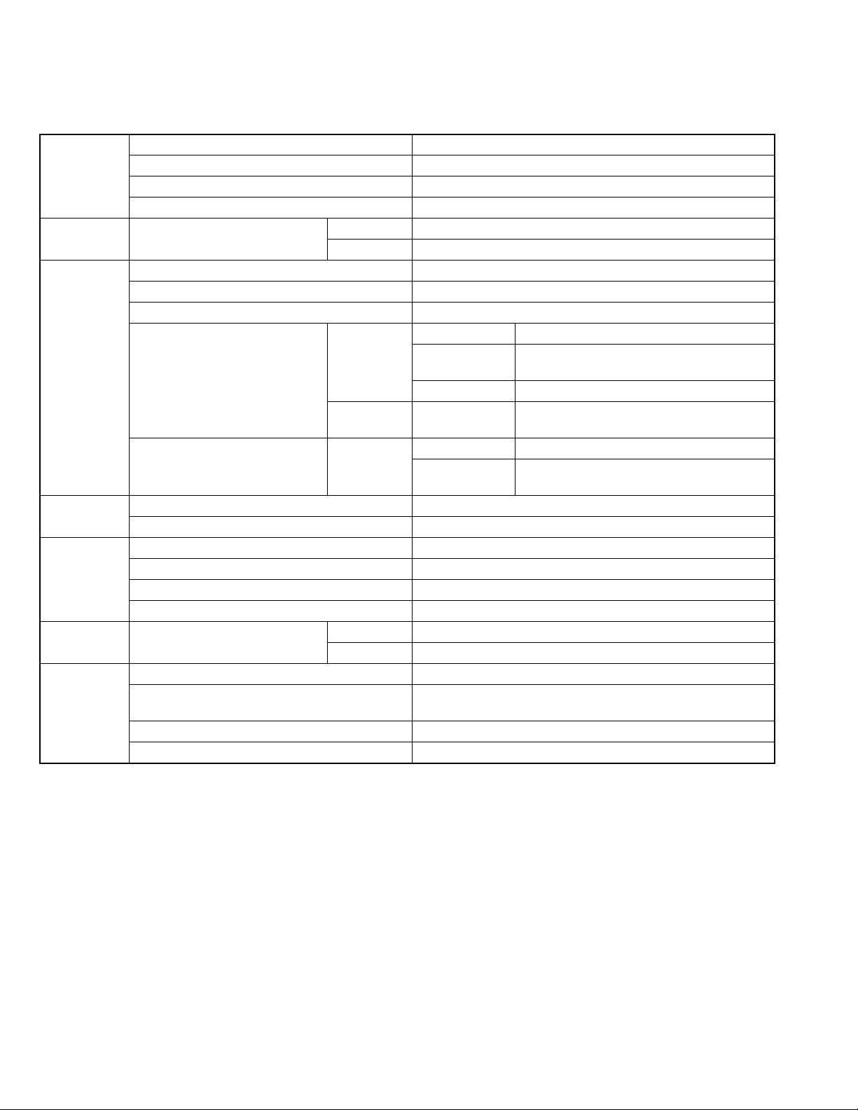
B,E,EN,EV
Center unit
SPECIFICATION
Output power Front
Center 130 W RMS at 4 Ω at 1 kHz with 10 % total harmonic distortion.
Surround
Subwoofer 140 W RMS at 4 Ω at 100 Hz with 10 % total harmonic distortion.
Audio section Digital Input*1 DIGITAL IN OPTICAL -21 dBm to -15 dBm (660 nm ±30 nm)
COAXIAL 0.5V(p-p)/75Ω
Video section Video System PAL
Horizontal Resolution 500 lines
Signal-to-Noise Ratio (Composite signal when “RGB” is selected)
Video Output Level (AV-Scart) Composite video 1.0 V(p-p)/75 Ω
(VIDEO OUT) Component (Y): 1.0 V(p-p)/75 Ω
Video Input Sensitivity/Impedance (VIDEO IN) Composite 1.0 V(p-p)/75 Ω
HDMI HDMI Input (VIDEO 1 IN) PASS THROUGH (up to 225 MHz)
HDMI Output (MONITOR OUT) 576p/720p/1080i
USB storage USB Specification Compatible with USB 2.0 Full Speed
Compatible Device Mass Storage Class
Compatible File System FAT16, FAT32
Bus Power Supply Max. 500 mA
Tuner section Tuner Range FM 87.50 MHz to 108.00 MHz
AM (MW) 522 kHz to 1 629 kHz
General Power Requirements AC 230 V , 50 Hz
Power Consumption 160 W (during operation)
Dimensions (W × H × D) 435 mm × 115 mm × 270 mm
Mass 6.8 kg
*1 Corresponding to Linear PCM Dolby Digital and DTS Digital Surround (with sampling frequency - 32 kHz 44.1 kHz 48 kHz)
140 W per channel RMS at 4 Ω at 1 kHz with 10 % total harmonic distortion.
130 W per channel RMS at 4 Ω at 1 kHz with 10 % total harmonic distortion.
54 dB
Y
C
RGB 0.7 V(p-p)/75 Ω
S-video (Y): 1.0 V(p-p)/75 Ω
1.0 W (in standby mode)
1.0 V(p-p)/75 Ω
0.3 V(p-p)/75 Ω
(PB/PR): 0.7V(p-p)/75Ω
(C): 0.3 V(p-p)/75 Ω
1-2 (No.MB638)
Page 3
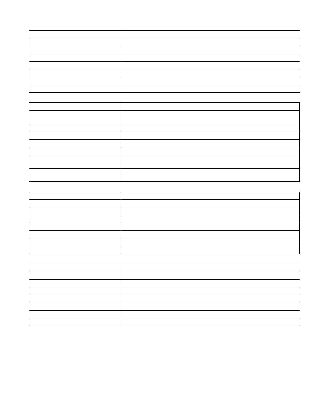
Subwoofer (SP-THD7W)
Type Bass-Reflex Type
Speaker 20 cm cone × 1
Power Handling Capacity 140 W
Impedance 4 Ω
Frequency Range 28 Hz to 200 Hz
Sound Pressure Level 75 dB/W•m
Dimensions (W × H × D) 353.5 mm × 351 mm × 248 mm
Mass 8.5 kg
Front speakers (SP-THD7F)
Type 2-Way 3-Speaker Bass-Reflex Type (Magnetically Shielded Type)
Speaker 8 cm cone x 2
3 cm dome x 1
Power Handling Capacity 140 W
Impedance 4 Ω
Frequency Range 75 Hz to 20 000 Hz
Sound Pressure Level 83 dB/W•m
Dimensions (W x H x D) 280 mm x 1 100 mm x 280 mm (with stand)
280 mm x 594 mm x 280 mm (without stand)
Mass 8.9 kg each (with stand)
6.5 kg each (without stand)
Center speaker (SP-THD7C)
Type 1-Way 2-Speaker Bass-Reflex Type (Magnetically Shielded Type)
Speaker 8 cm cone × 2
Power Handling Capacity 140 W
Impedance 4 Ω
Frequency Range 75 Hz to 20 000 Hz
Sound Pressure Level 84 dB/W•m
Dimensions (W × H × D) 435 mm × 100 mm × 118 mm
Mass 2.2 kg
Surround speakers (SP-THD7S)
Type 1-Way Bass-Reflex Type (Magnetically Shielded Type)
Speaker 8 cm cone × 1
Power Handling Capacity 140 W
Impedance 4 Ω
Frequency Range 75 Hz to 20 000 Hz
Sound Pressure Level 77 dB/W•m
Dimensions (W × H × D) 98.5 mm × 215 mm × 118 mm
Mass 1.0 kg each
(No.MB638)1-3
Page 4
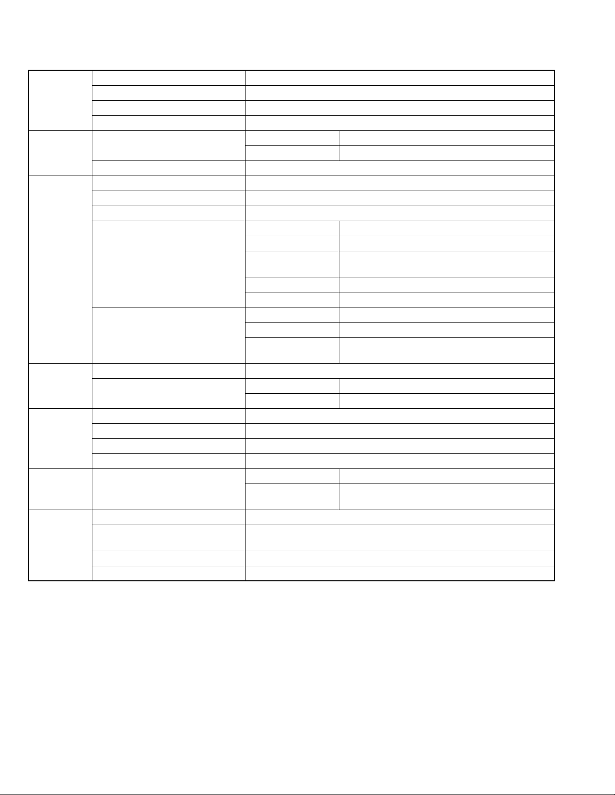
A
Center unit
Output power Front 140 W per channel RMS at 4 Ω at 1 kHz with 10 % total harmonic distortion.
Center 130 W RMS at 4 Ω at 1 kHz with 10 % total harmonic distortion.
Surround 130 W per channel RMS at 4 Ω at 1 kHz with 10 % total harmonic distortion.
Subwoofer 140 W RMS at 4 Ω at 100 Hz with 10 % total harmonic distortion.
Audio section Digital Input* DIGITAL IN OPTICAL -21 dBm to -15 dBm (660 nm ±30 nm)
COAXIAL 0.5 V(p-p)/75 Ω
Analog input VIDEO 2 AUDIO IN
Video section Video System PAL/NTSC
Horizontal Resolution 500 lines
Signal-to-Noise Ratio 64 dB
Video Output Level Composite 1.0 V(p-p)/75 Ω
S-video-Y 1.0 V(p-p)/75 Ω
S-video-C For PAL: 0.3 V(p-p)/75 Ω
For NTSC: 0.286 V(p-p)/75 Ω
Component-Y 1.0 V(p-p)/75 Ω
Component-PB/PR 0.7 V(p-p)/75 Ω
Video Input Sensitivity/Impedance Composite 1.0 V(p-p)/75 Ω
S-video-Y 1.0 V(p-p)/75 Ω
S-video-C For PAL: 0.3 V(p-p)/75 Ω
For NTSC: 0.286 V(p-p)/75 Ω
HDMI HDMI Input (VIDEO 1 IN) PASS THROUGH (up to 225 MHz)
HDMI Output (MONITOR OUT) For PAL 576p/720p/1080i
For NTSC 480p/720p/1080i
USB storage USB Specification Compatible with USB 2.0 Full Speed
Compatible Device Mass Storage Class
Compatible File System FAT16, FAT32
Bus Power Supply Max. 500 mA
Tuner section Tuner Range FM 87.50 MHz to 108.00 MHz
AM At 10 kHz intervals: 530 kHz to 1 710 kHz
At 9 kHz intervals: 531 kHz to 1 710 kHz
General Power Requirements AC 240 V , 50 Hz
Power Consumption 160 W (during operation)
4.0 W (in standby mode)
Dimensions (W × H × D) 435 mm × 115 mm × 270 mm
Mass 6.8 kg
* Corresponding to Linear PCM Dolby Digital and DTS Digital Surround (with sampling frequency - 32 kHz 44.1 kHz 48 kHz)
1-4 (No.MB638)
Page 5
Subwoofer
Type Bass-Reflex Type
Speaker 20 cm cone × 1
Power Handling Capacity 140 W
Impedance 4 Ω
Frequency Range 28 Hz to 200 Hz
Sound Pressure Level 75 dB/W•m
Dimensions (W × H × D) 353.5 mm × 351 mm × 248 mm
Mass 8.5 kg
Front speakers (SP-THD7F)
Type 2-Way 3-Speaker Bass-Reflex Type (Magnetically Shielded Type)
Speaker 8 cm cone × 2
3 cm dome × 1
Power Handling Capacity 140 W
Impedance 4 Ω
Frequency Range 75 Hz to 20 000 Hz
Sound Pressure Level 83 dB/W•m
Dimensions (W × H × D) 280 mm x 1 100 mm x 280 mm (with stand)
280 mm x 594 mm x 280 mm (without stand)
Mass 8.9 kg each (with stand)
6.5 kg each (without stand)
Center speaker (SP-THD7C)
Type 1-Way 2-Speaker Bass-Reflex Type (Magnetically Shielded Type)
Speaker 8 cm cone × 2
Power Handling Capacity 140 W
Impedance 4 Ω
Frequency Range 75 Hz to 20 000 Hz
Sound Pressure Level 84 dB/W•m
Dimensions (W × H × D) 435 mm × 100 mm × 118 mm
Mass 2.2 kg
Surround speakers (SP-THD7S)
Type 1-Way Bass-Reflex Type (Magnetically Shielded Type)
Speaker 8 cm cone × 1
Power Handling Capacity 140 W
Impedance 4 Ω
Frequency Range 75 Hz to 20 000 Hz
Sound Pressure Level 77 dB/W•m
Dimensions (W × H × D) 98.5 mm × 215 mm × 118 mm
Mass 1.0 kg each
(No.MB638)1-5
Page 6
US,UX,UG
Center unit
Output power Front 140 W per channel RMS at 4 Ω at 1 kHz with 10 % total harmonic distortion.
Center 130 W RMS at 4 Ω at 1 kHz with 10 % total harmonic distortion.
Surround 130 W per channel RMS at 4 Ω at 1 kHz with 10 % total harmonic distortion.
Subwoofer 140 W RMS at 4 Ω at 100 Hz with 10 % total harmonic distortion.
Audio section Digital Input*1 DIGITAL IN OPTICAL -21 dBm to -15 dBm (660 nm ±30 nm)
COAXIAL 0.5V(p-p)/75Ω
Analog input VIDEO 2 AUDIO IN
Analog output AUDIO OUT
Video section Video System PAL/NTSC
Horizontal Resolution 500 lines
Signal-to-Noise Ratio 64 dB
Video Output Level Composite 1.0 V(p-p)/75 Ω
S-video-Y 1.0 V(p-p)/75 Ω
S-video-C For PAL: 0.3 V(p-p)/75 Ω
For NTSC: 0.286 V(p-p)/75 Ω
Component-Y 1.0 V(p-p)/75 Ω
Component-PB/PR 0.7 V(p-p)/75 Ω
Video Input Sensitivity/Impedance
(VIDEO 2 IN)
HDMI HDMI Input (VIDEO 1 IN) PASS THROUGH (up to 225 MHz)
HDMI Output (MONITOR OUT) For PAL 576p/720p/1080i
USB storage USB Specification Compatible with USB 2.0 Full Speed
Compatible Device Mass Storage Class
Compatible File System FAT16, FAT32
Bus Power Supply Max. 500 mA
Tuner section Tuner Range FM 87.50 MHz to 108.00 MHz
General Power Requirements AC 110 V/127 V/220 V - 240 V 50/60 Hz (selectable with the voltage selector)
Power Consumption 160 W (during operation)
Dimensions (W × H × D) 435 mm × 115 mm × 270 mm
Mass 6.8 kg
Composite 1.0 V(p-p)/75 Ω
S-video-Y 1.0 V(p-p)/75 Ω
S-video-C For PAL: 0.3 V(p-p)/75 Ω
For NTSC: 0.286 V(p-p)/75 Ω
For NTSC 480p/720p/1080i
AM (At 10 kHz intervals) For Saudi Arabia: 530 kHz to 1 600 kHz
For the other countries: 530 kHz to 1 710 kHz
AM (At 9 kHz intervals) For Saudi Arabia: 531 kHz to 1 602 kHz
For the other countries: 531 kHz to 1 710 kHz
4.0 W (in standby mode)
*1 Corresponding to Linear PCM Dolby Digital and DTS Digital Surround (with sampling frequency - 32 kHz 44.1 kHz 48 kHz)
1-6 (No.MB638)
Page 7
Subwoofer (SP-THD7W)
Type Bass-Reflex Type
Speaker 20 cm cone × 1
Power Handling Capacity 140 W
Impedance 4 Ω
Frequency Range 28 Hz to 200 Hz
Sound Pressure Level 75 dB/W•m
Dimensions (W × H × D) 353.5 mm × 351 mm × 248 mm
Mass 8.5 kg
Front speakers (SP-THD7F)
Type 2-Way 3-Speaker Bass-Reflex Type (Magnetically Shielded Type)
Speaker 8 cm cone × 2
3 cm dome × 1
Power Handling Capacity 140 W
Impedance 4 Ω
Frequency Range 75 Hz to 20 000 Hz
Sound Pressure Level 83 dB/W•m
Dimensions (W × H × D) 280 mm x 1 100 mm x 280 mm (with stand)
280 mm x 594 mm x 280 mm (without stand)
Mass 8.9 kg each (with stand)
6.5 kg each (without stand)
Center speaker (SP-THD7C)
Type 1-Way 2-Speaker Bass-Reflex Type (Magnetically Shielded Type)
Speaker 8 cm cone × 2
Power Handling Capacity 140 W
Impedance 4 Ω
Frequency Range 75 Hz to 20 000 Hz
Sound Pressure Level 84 dB/W•m
Dimensions (W × H × D) 435 mm × 100 mm × 118 mm
Mass 2.2 kg
Surround speakers (SP-THD7S)
Type 1-Way Bass-Reflex Type (Magnetically Shielded Type)
Speaker 8 cm cone × 1
Power Handling Capacity 140 W
Impedance 4 Ω
Frequency Range 75 Hz to 20 000 Hz
Sound Pressure Level 77 dB/W•m
Dimensions (W × H × D) 98.5 mm × 215 mm × 118 mm
Mass 1.0 kg each
(No.MB638)1-7
Page 8
SECTION 1
PRECAUTION
1.1 Safety Precautions
(1) This design of this product contains special hardware and
many circuits and components specially for safety purposes. For continued protection, no changes should be made
to the original design unless authorized in writing by the
manufacturer. Replacement parts must be identical to
those used in the original circuits. Services should be performed by qualified personnel only.
(2) Alterations of the design or circuitry of the product should
not be made. Any design alterations of the product should
not be made. Any design alterations or additions will void
the manufacturers warranty and will further relieve the
manufacture of responsibility for personal injury or property
damage resulting therefrom.
(3) Many electrical and mechanical parts in the products have
special safety-related characteristics. These characteristics are often not evident from visual inspection nor can the
protection afforded by them necessarily be obtained by using replacement components rated for higher voltage, wattage, etc. Replacement parts which have these special
safety characteristics are identified in the Parts List of Service Manual. Electrical components having such features
are identified by shading on the schematics and by ( ) on
the Parts List in the Service Manual. The use of a substitute
replacement which does not have the same safety characteristics as the recommended replacement parts shown in
the Parts List of Service Manual may create shock, fire, or
other hazards.
(4) The leads in the products are routed and dressed with ties,
clamps, tubings, barriers and the like to be separated from
live parts, high temperature parts, moving parts and/or
sharp edges for the prevention of electric shock and fire
hazard. When service is required, the original lead routing
and dress should be observed, and it should be confirmed
that they have been returned to normal, after reassembling.
(5) Leakage shock hazard testing
After reassembling the product, always perform an isolation check on the exposed metal parts of the product (antenna terminals, knobs, metal cabinet, screw heads,
headphone jack, control shafts, etc.) to be sure the product
is safe to operate without danger of electrical shock.Do not
use a line isolation transformer during this check.
• Plug the AC line cord directly into the AC outlet. Using a
"Leakage Current Tester", measure the leakage current
from each exposed metal parts of the cabinet, particularly any exposed metal part having a return path to the
chassis, to a known good earth ground. Any leakage current must not exceed 0.5mA AC (r.m.s.).
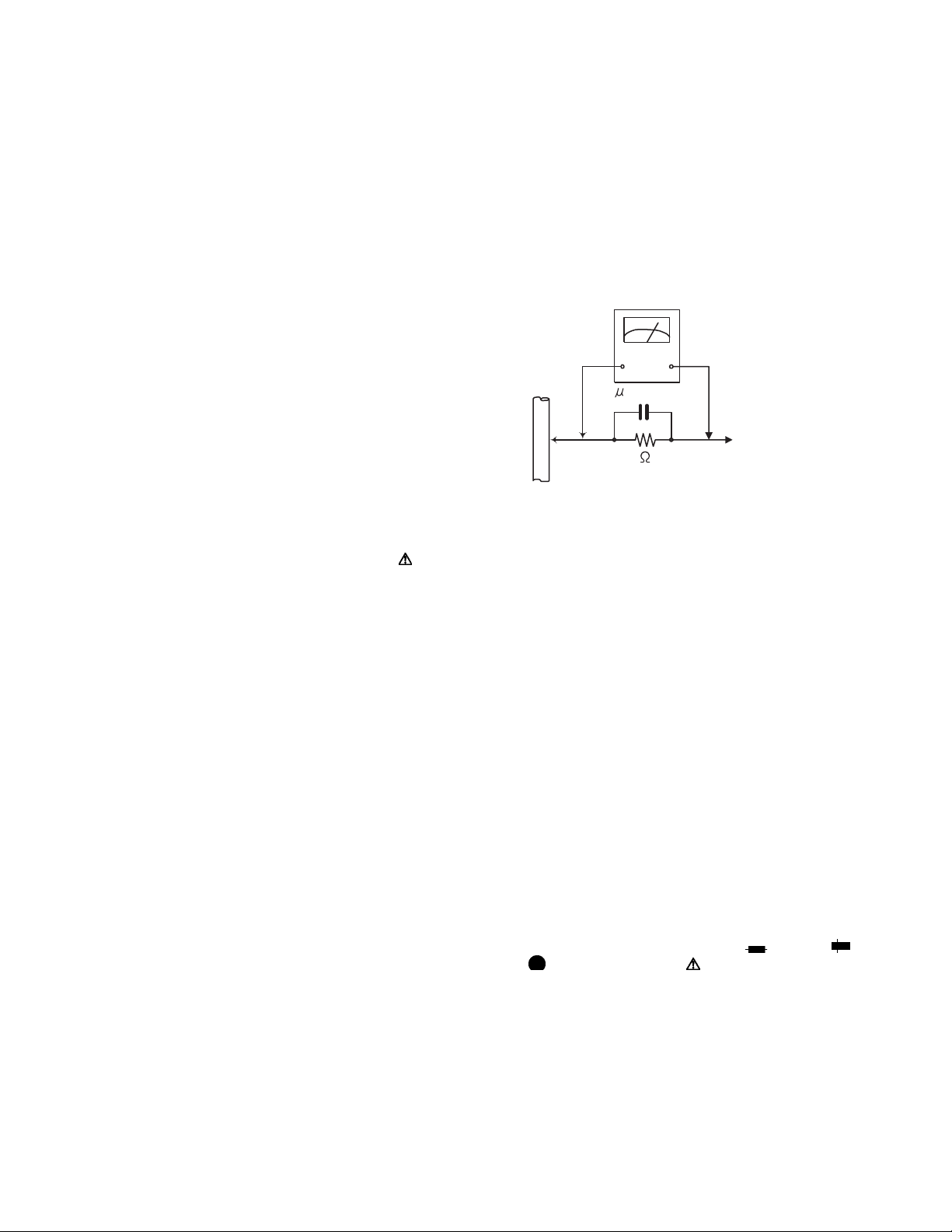
• Alternate check method
Plug the AC line cord directly into the AC outlet. Use an
AC voltmeter having, 1,000Ω per volt or more sensitivity
in the following manner. Connect a 1,500Ω 10W resistor
paralleled by a 0.15µF AC-type capacitor between an ex-
posed metal part and a known good earth ground.
Measure the AC voltage across the resistor with the AC
voltmeter.
Move the resistor connection to each exposed metal
part, particularly any exposed metal part having a return
path to the chassis, and measure the AC voltage across
the resistor. Now, reverse the plug in the AC outlet and
repeat each measurement. Voltage measured any must
not exceed 0.75 V AC (r.m.s.). This corresponds to 0.5
mA AC (r.m.s.).
AC VOLTMETER
(Having 1000
ohms/volts,
or more sensitivity)
0.15 F AC TYPE
Place this
probe on
1500 10W
Good earth ground
1.2 Warning
(1) This equipment has been designed and manufactured to
meet international safety standards.
(2) It is the legal responsibility of the repairer to ensure that
these safety standards are maintained.
(3) Repairs must be made in accordance with the relevant
safety standards.
(4) It is essential that safety critical components are replaced
by approved parts.
(5) If mains voltage selector is provided, check setting for local
voltage.
1.3 Caution
Burrs formed during molding may be left over on some parts
of the chassis.
Therefore, pay attention to such burrs in the case of preforming repair of this system.
1.4 Critical parts for safety
In regard with component parts appearing on the silk-screen
printed side (parts side) of the PWB diagrams, the parts that are
printed over with black such as the resistor ( ), diode ( )
and ICP ( ) or identified by the " " mark nearby are critical
for safety. When replacing them, be sure to use the parts of the
same type and rating as specified by the manufacturer.
(This regulation dose not Except the J and C version)
each exposed
metal part.
1-8 (No.MB638)
Page 9
1.5 Safety Precautions (U.K only)
(1) This design of this product contains special hardware and many circuits and components specially for safety purposes. For con-
tinued protection, no changes should be made to the original design unless authorized in writing by the manufacturer. Replacement parts must be identical to those used in the original circuits.
(2) Any unauthorised design alterations or additions will void the manufacturer's guarantee; furthermore the manufacturer cannot
accept responsibility for personal injury or property damage resulting therefrom.
(3) Essential safety critical components are identified by ( ) on the Parts List and by shading on the schematics, and must never
be replaced by parts other than those listed in the manual. Please note however that many electrical and mechanical parts in
the product have special safety related characteristics. These characteristics are often not evident from visual inspection. Parts
other than specified by the manufacturer may not have the same safety characteristics as the recommended replacement parts
shown in the Parts List of the Service Manual and may create shock, fire, or other hazards.
(4) The leads in the products are routed and dressed with ties, clamps, tubings, barriers and the like to be separated from live parts,
high temperature parts, moving parts and/or sharp edges for the prevention of electric shock and fire hazard. When service is
required, the original lead routing and dress should be observed, and it should be confirmed that they have been returned to
normal, after re-assembling.
1.5.1 Warning
(1) Service should be performed by qualified personnel only.
(2) This equipment has been designed and manufactured to meet international safety standards.
(3) It is the legal responsibility of the repairer to ensure that these safety standards are maintained.
(4) Repairs must be made in accordance with the relevant safety standards.
(5) It is essential that safety critical components are replaced by approved parts.
(6) If mains voltage selector is provided, check setting for local voltage.
Burrs formed during molding may be left over on some parts of the chassis. Therefore,
pay attention to such burrs in the case of preforming repair of this system.
(No.MB638)1-9
Page 10
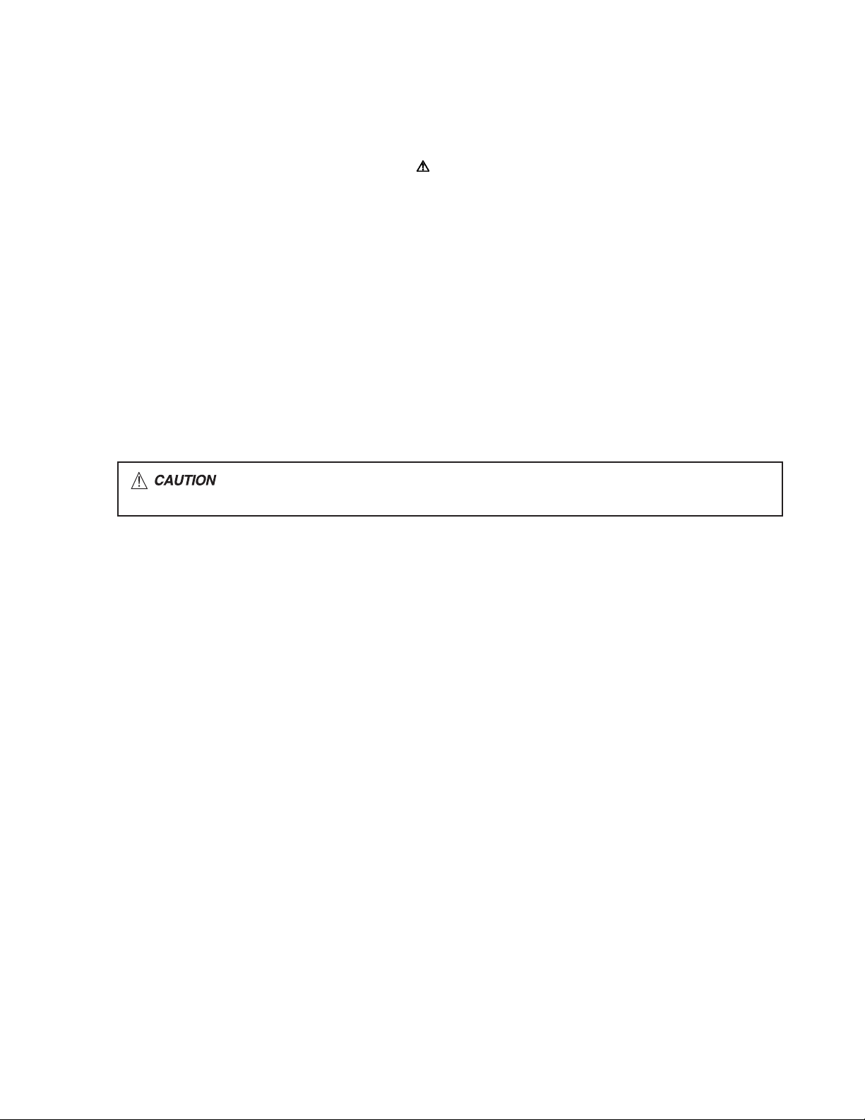
1.6 Preventing static electricity
Electrostatic discharge (ESD), which occurs when static electricity stored in the body, fabric, etc. is discharged, can destroy the laser
diode in the traverse unit (optical pickup). Take care to prevent this when performing repairs.
1.6.1 Grounding to prevent damage by static electricity
Static electricity in the work area can destroy the optical pickup (laser diode) in devices such as laser products.
Be careful to use proper grounding in the area where repairs are being performed.
(1) Ground the workbench
Ground the workbench by laying conductive material (such as a conductive sheet) or an iron plate over it before placing the
traverse unit (optical pickup) on it.
(2) Ground yourself
Use an anti-static wrist strap to release any static electricity built up in your body.
(caption)
Anti-static wrist strap
1M
Conductive material
(conductive sheet) or iron palate
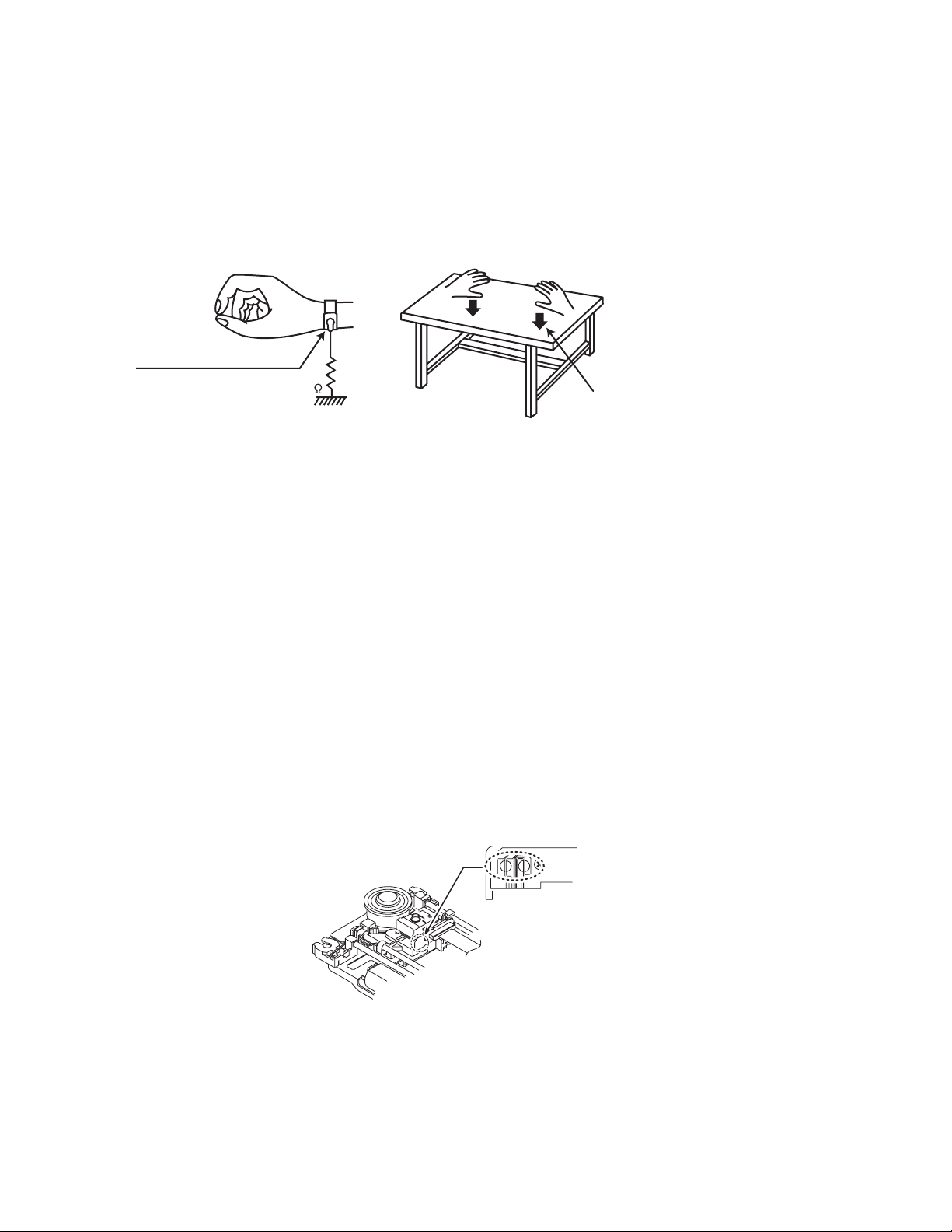
(3) Handling the optical pickup
• In order to maintain quality during transport and before installation, both sides of the laser diode on the replacement optical
pickup are shorted. After replacement, return the shorted parts to their original condition.
(Refer to the text.)
• Do not use a tester to check the condition of the laser diode in the optical pickup. The tester's internal power source can easily
destroy the laser diode.
1.7 Handling the traverse unit (optical pickup)
(1) Do not subject the traverse unit (optical pickup) to strong shocks, as it is a sensitive, complex unit.
(2) Cut off the shorted part of the flexible cable using nippers, etc. after replacing the optical pickup. For specific details, refer to the
replacement procedure in the text. Remove the anti-static pin when replacing the traverse unit. Be careful not to take too long a
time when attaching it to the connector.
(3) Handle the flexible cable carefully as it may break when subjected to strong force.
(4) I t is not possible to adjust the semi-fixed resistor that adjusts the laser power. Do not turn it.
1.8 Attention when traverse unit is decomposed
*Please refer to "Disassembly method" in the text for the pickup unit.
• Apply solder to the short land sections before the card wire is disconnected from the connecto on the servo board. (If the card wire
is disconnected without applying solder, the pickup may be destroyed by static electricity.)
• In the assembly, be sure to remove solder from the short land sections after connecting the card wire.
Solder short land section
1-10 (No.MB638)
Page 11
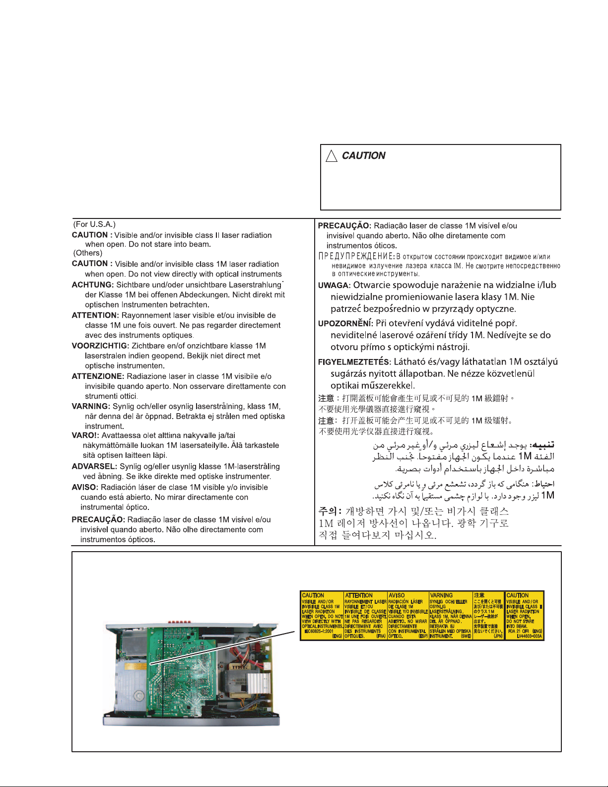
1.9 Important for laser products
1.CLASS 1 LASER PRODUCT
2.CAUTION :
(For U.S.A.) Visible and/or invisible class II laser radiation
when open. Do not stare into beam.
(Others) Visible and/or invisible class 1M laser radiation
when open. Do not view directly with optical instruments.
3.CAUTION : Visible and/or invisible laser radiation when
open and inter lock failed or defeated. Avoid direct
exposure to beam.
4.CAUTION : This laser product uses visible and/or invisible
laser radiation and is equipped with safety switches which
prevent emission of radiation when the drawer is open and
the safety interlocks have failed or are defeated. It is
dangerous to defeat the safety switches.
5.CAUTION : If safety switches malfunction, the laser is able
to function.
6.CAUTION : Use of controls, adjustments or performance of
procedures other than those specified here in may result in
hazardous radiation exposure.
!
Please use enough caution not to
see the beam directly or touch it
in case of an adjustment or operation
check.
REPRODUCTION AND POSITION OF LABELS and PRINT
WARNING LABEL and PRINT
(No.MB638)1-11
Page 12
SECTION 2
SPECIFIC SERVICE INSTRUCTIONS
This service manual does not describe SPECIFIC SERVICE INSTRUCTIONS.
SECTION 3
DISASSEMBLY
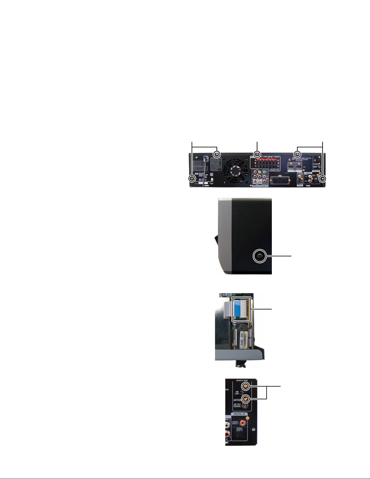
3.1 Main body (Used figure are TH-D7E and TH-D7US)
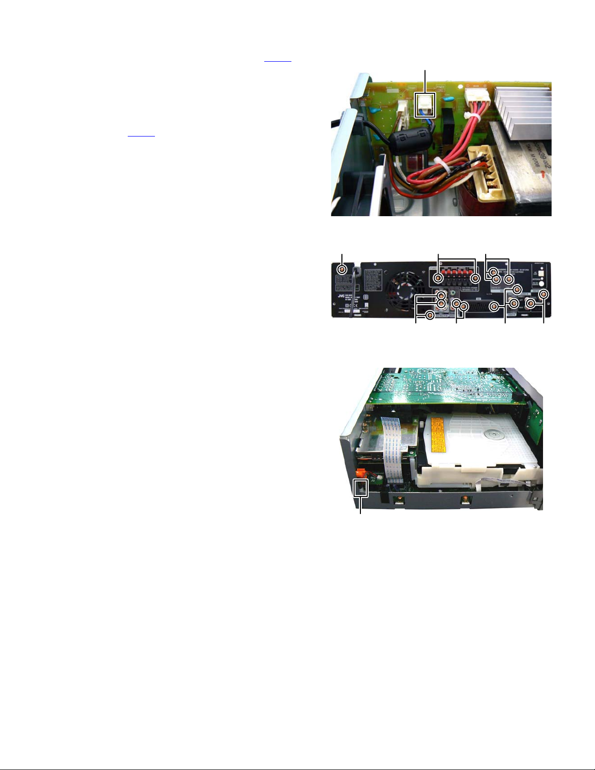
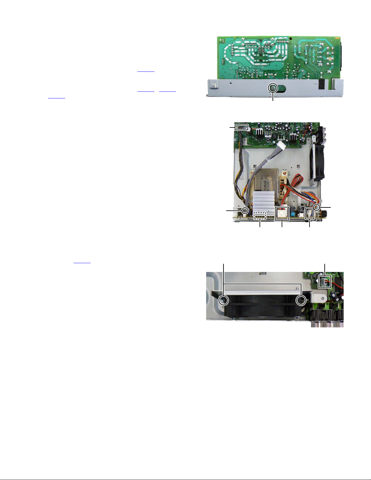
3.1.1 Removing the METAL COVER (See Fig.1, 2)
(1) Remove the four screws A attaching the METAL COVER.
(See Fig.1)
(2) Remove the one screw B attaching the METAL COVER.
(See Fig.1)
When remove the screw B use a screwdriver shown as
follows.
TORX Driver: size T10
Parts number: DR-L70
Remove the two screws C attaching the both side of
(3)
METAL COVER. (See Fig.2)
AAB
Fig.1
3.1.2 Removing the TUNER PACK (See Fig.3, 4)
(1) Disconnect the card wire from the MAIN BOARD assembly
connected to TUNER PACK. (See Fig.3)
(2) Remove the two screws D attaching the TUNER PACK.
(See Fig.4)
C
Fig.2
Tunerpack
connector
Fig.3
D
1-12 (No.MB638)
Fig.4
Page 13
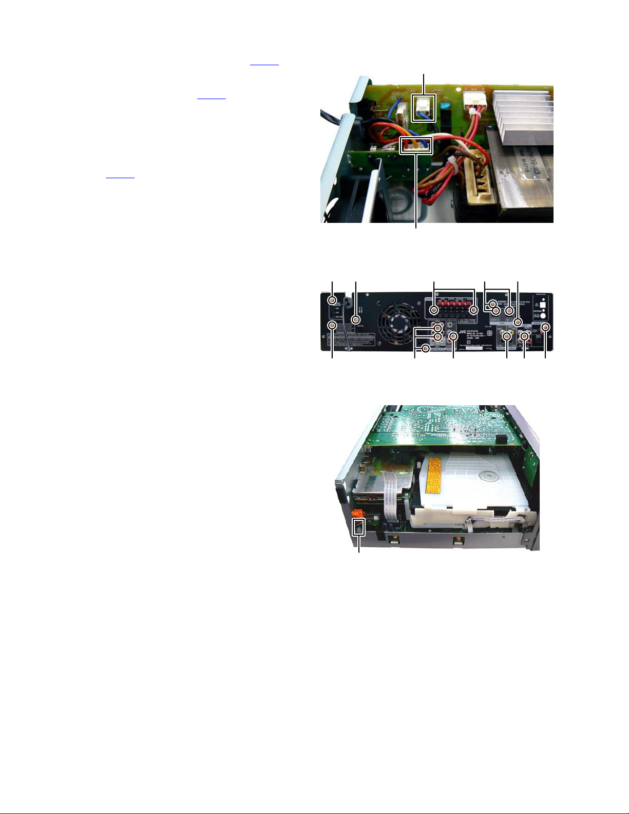
3.1.3 Removing the REAR PANEL (for European version) (See Fig.5 to 7)
(1) Disconnect the POWER CORD from connector CN101
the POWER BOARD assembly. (See Fig.5)
(2) Remove the three screws E attaching the HDMI BOARD
assembly. (See Fig.6)
(3) Remove the 13 screws F attaching the REAR PANEL.
(When remove the most right side screw, DIGITAL IN
JACK BOARD assembly come off, disconnect the connector wire from CN302
Fig.6, 7)
of the MAIN BOARD assembly.) (See
of
CN101
Fig.5
F
CN302
EF
FF FF
Fig.6
Fig.7
(No.MB638)1-13
Page 14
3.1.4 Removing the REAR PANEL (for Asian version) (See Fig.8 to 10)
(1) Disconnect the POWER CORD from connector CN101
the POWER BOARD assembly. (See Fig.8)
(2) Disconnect the connector wire from POWER BOARD as-
sembly connected to connector CN111
BOARD assembly. (See Fig.8)
(3) Remove the three screws G attaching the HDMI BOARD
assembly. (See Fig.9)
(4) Remove the 13 screws H attaching the REAR PANEL.
(When remove the most right side screw, DIGITAL IN
JACK BOARD assembly come off, disconnect the connector wire from CN302
Fig.9, 10)
of the MAIN BOARD assembly.) (See
of the FUSE
of
CN101
CN111
Fig.8
GHHHH
HHHHHH
Fig.9
CN302
Fig.10
1-14 (No.MB638)
Page 15
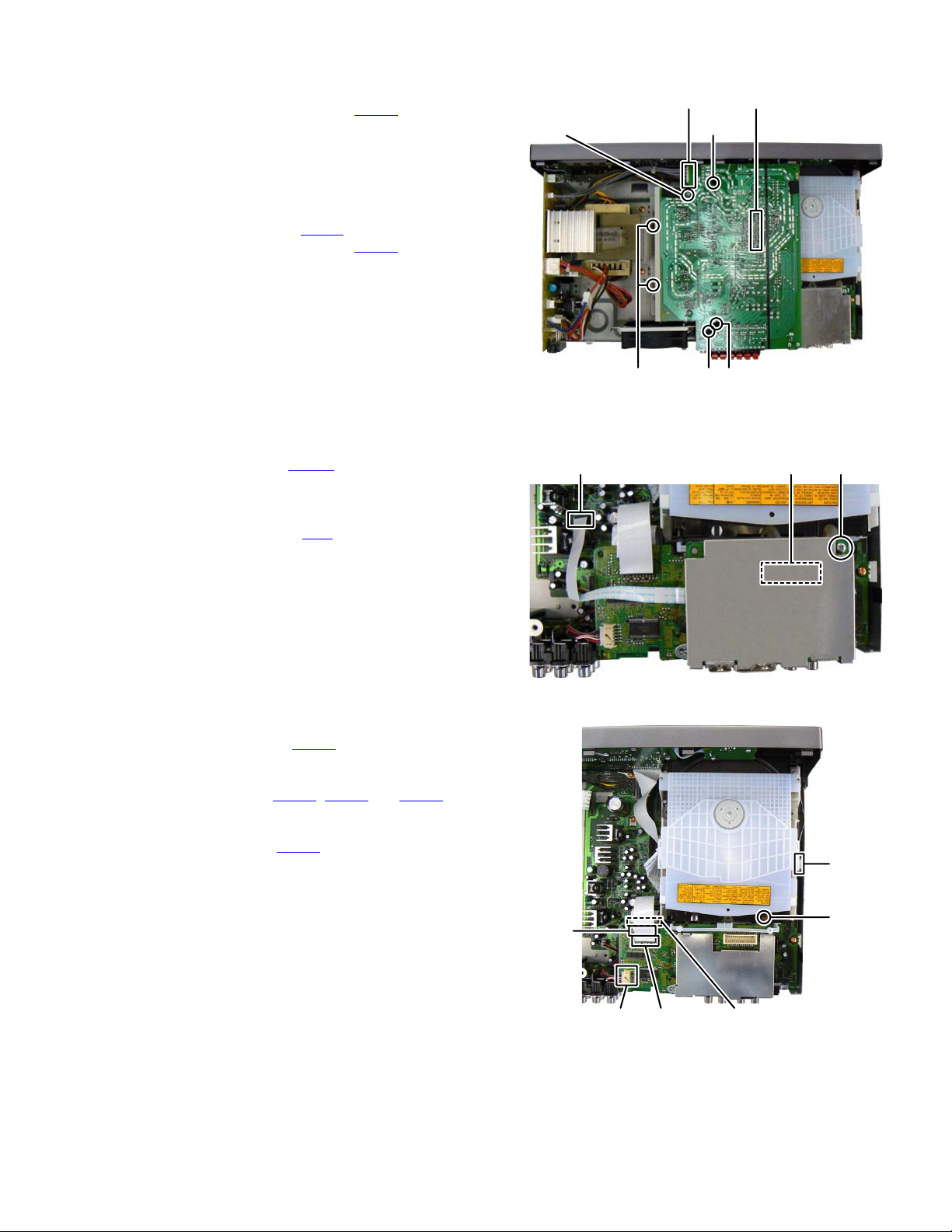
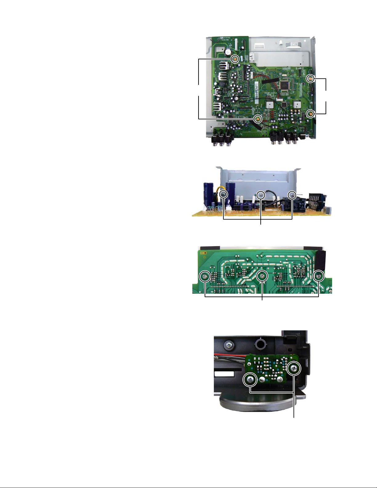
3.1.5 Removing the AMP BOARD assembly (See Fig.11)
Disconnect the connector wire from POWER BOARD
(1)
CN501
CN514
of the AMP
of the CON-
assembly connected to connector
BOARD assembly.
(2) Remove the one screw J attaching the EARTH WIRE from
FL BOARD assembly. (only European version)
(3) Remove the two screws K attaching the HEAT SINK
BRACKET.
(4) Remove the three screws L attaching the BRACKET.
Disconnect the connector
(5)
assembly connected to connector
NECTION BOAR assembly.
(6) Remove the CONNECTION BOARD assembly from MAIN
BOARD assembly.
3.1.6 Removing the HDMI BOARD assembly (See Fig.12)
(1)
Disconnect the card wire from HDMI BOARD assembly
connected to connector CN203
assembly.
(2)
Remove the one screw M attaching the HDMI BOARD
assembly.
(3)
Disconnect the connector CN2 of the HDMI BOARD
assembly connected to the DVD FRONT END BOARD
assembly.
CN504
of the AMP BOARD
of the MAIN BOARD
(only Europian
JL
version)
CN501 CN504
(Connection board
CN514 inside)
KLL
Fig.11
CN2CN203
M
3.1.7 Removing the DVD MECHANISM assembly (See Fig.13)
Disconnect the card wire from USB BOARD assembly
(1)
CN811
connected to connector
BOARD assembly.
(2) Disconnect the card wire from MAIN BOARD assembly
connected to connector CN701
FRONT END BOARD assembly.
(3) Disconnect the card wire from LOADING BASE assembly
connected to connector CN212
sembly.
(4) Remove the one screw N attaching the DVD MECHANISM
assembly.
of the FRONT END
, CN712 and CN801 of the
of the MAIN BOARD as-
CN801
CN811 CN712
Fig.12
CN212
N
CN701
Fig.13
(No.MB638)1-15
Page 16
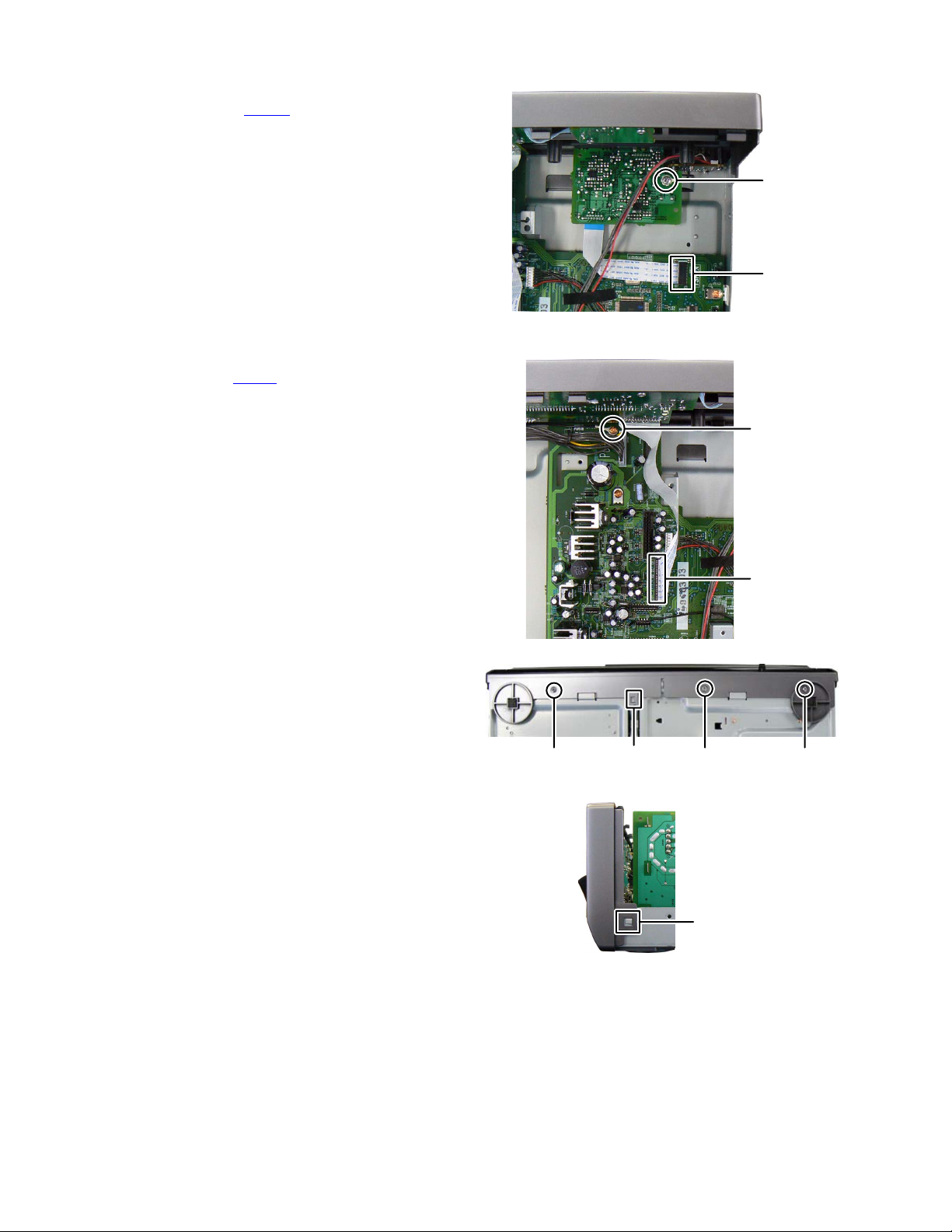
3.1.8 Removing the iPod BOARD assembly (See Fig.14)
(1)
Disconnect the card wire from iPod BOARD assembly
connected to connector CN210
assembly.
(2)
Remove the one screw P attaching the iPod BOARD
assembly.
3.1.9 Removing the FRONT PANEL assembly (See Fig.15 to 17)
(1) Disconnect the card wire from FRONT PANEL assembly
connected to connector CN211
sembly. (See Fig.15)
(2) Remove the one screw Q attaching the EARTH WIRE.
(See Fig.15)
(3) Remove the three screws R attaching the bottom side of
FRONT PANEL assembly. (See Fig.16)
Disengage hook a of the bottom side of FRONT PANEL
(4)
assembly and hook b of the both side of FRONT PANEL
assembly. (See Fig.16, 17)
of the MAIN BOARD
of the MAIN BOARD as-
P
CN210
Fig.14
Q
CN211
Fig.15
hook
RRR
a
Fig.16
Fig.17
hook
b
1-16 (No.MB638)
Page 17
3.1.10 Removing the POWER BOARD assembly (See Fig.18, 19)
(1) Remove the one screw S attaching the POWER BOARD
assembly. (See Fig.18)
(2) Remove the two screws T attaching the BRACKET. (See
Fig.19)
Disconnect the connector wire from POWER BOARD
(3)
CN151
assembly connected to connector
BOARD assembly. (See Fig.19)
(4) Disconnect the connector wires from POWER TRANS-
FORMER connected to connector CN102
CN104 of the POWER BOARD assembly. (See Fig.19)
of the MAIN
, CN103 and
S
Fig.18
CN151
3.1.11 Removing the FAN (See Fig.20)
(1) Disconnect the connector wire from the FAN connected to
connector CN152
(2) Remove the two screws U attaching the FAN.
of the MAIN BOARD assembly.
T
U
T
CN104 CN103 CN102
Fig.19
CN152
Fig.20
(No.MB638)1-17
Page 18
3.1.12 Removing the MAIN BOARD assembly (See Fig.21)
(1)
Remove the four screws V attaching the MAIN BOARD
assembly.
3.1.13 Removing the HEAT SINK (See Fig.22, 23)
(1) Remove the three screws W attaching the HEAT SINK.
(See Fig.22)
(2) Remove the three screws X attaching the HEAT SINK.
(See Fig.23)
V
V
Fig.21
W
Fig.22
3.1.14 Removing the USB BOARD assembly (See Fig.24)
Remove the two screws Y attaching the USB BOARD
(1)
assembly.
1-18 (No.MB638)
X
Fig.23
Y
Fig.24
Page 19
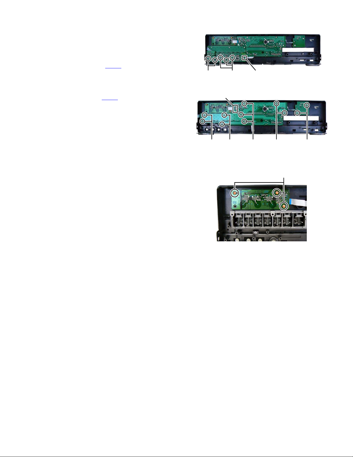
3.1.15 Removing the FL BOARD assembly (See Fig.25, 26)
(1) Remove the MIC volume knob. (for Asian version).
(2) Remove the three screws Z attaching the MIC BOARD
assembly. (for Asian version is MIC BOARD assembly,
for European version is BRACKET BOARD) (See Fig.
Disconnect the card wire from FL BOARD assembly
(3)
CN711
connected to connector
sembly. (for Asian version) (See Fig.25)
(4) Remove the two screws AA attaching the PHONE JACK
BOARD assembly. (See Fig.25)
(5) Disconnect the card wire from TOUCH BOARD assembly
connected to connector CN601
bly. (See Fig.26)
(6) Remove the two screws BB attaching the LED BOARD
assembly. (See Fig.
Remove the nine screws CC attaching the FL BOARD
(7)
assembly. (See Fig.26)
3.1.16 Removing the TOUCH BOARD assembly (See Fig.27)
(1) Remove the three screws DD attaching the TOUCH
BOARD assembly.
26)
of the MIC BOARD as-
of the FL BOARD assem-
25)
Z CN711AA
Fig.25
CN601
BBCCCCCCCC
Fig.26
DD
Fig.27
(No.MB638)1-19
Page 20
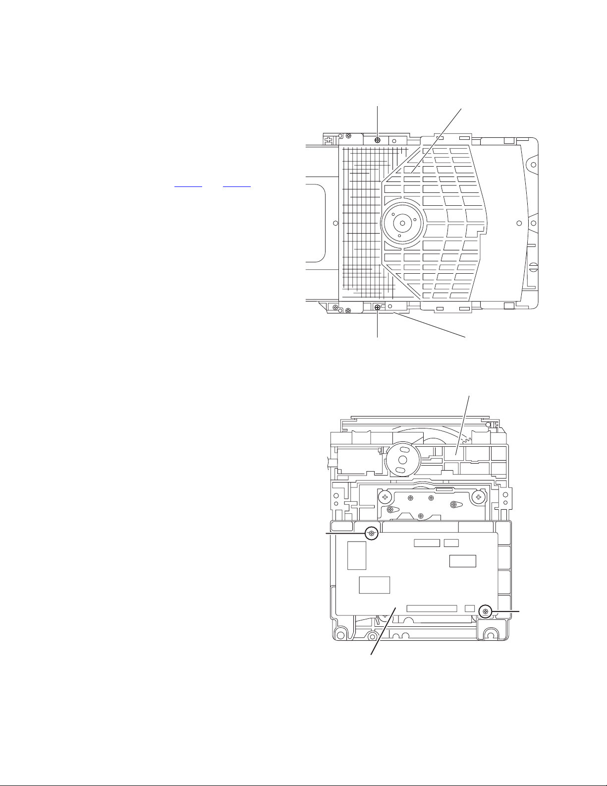
3.2 DVD mechanism
3.2.1 Removing the traverse mechanism
(See Fig.1 to 6)
(1) Remove the two screws A attaching the tramecha holder
from top side of DVD mechanism assembly. (See Fig.1)
(2) Remove the two screws B attaching the DVD module
board. (See Fig.2)
(3) Remove the four screws C attaching the CB holder and
take out it. (See Fig.3)
(4) Remove the four screws D attaching the traverse mecha-
nism. (See Fig.4)
(5) Solder the solder part of DVD pick up. (See Fig.5)
(6) Disconnect the card wire from CN101
DVD module board. (See Fig. 6)
Caution:
• Solder the short land section on the DVD pickup before dis-
connecting the card wire from the connector on the DVD
pickup. If the card wire is disconnected without attaching solders, the pickup may be destroyed by static electricity.
• When attaching the DVD pickup, be sure to remove solders
from the short land section after connecting the card wire to
the connector on the DVD pickup.
and CN201 on the
A
Clamper base
B
A
DVD mechanism assembly
Fig.1
DVD mechanism assembly
B
1-20 (No.MB638)
DVD module board
Fig.2
Page 21
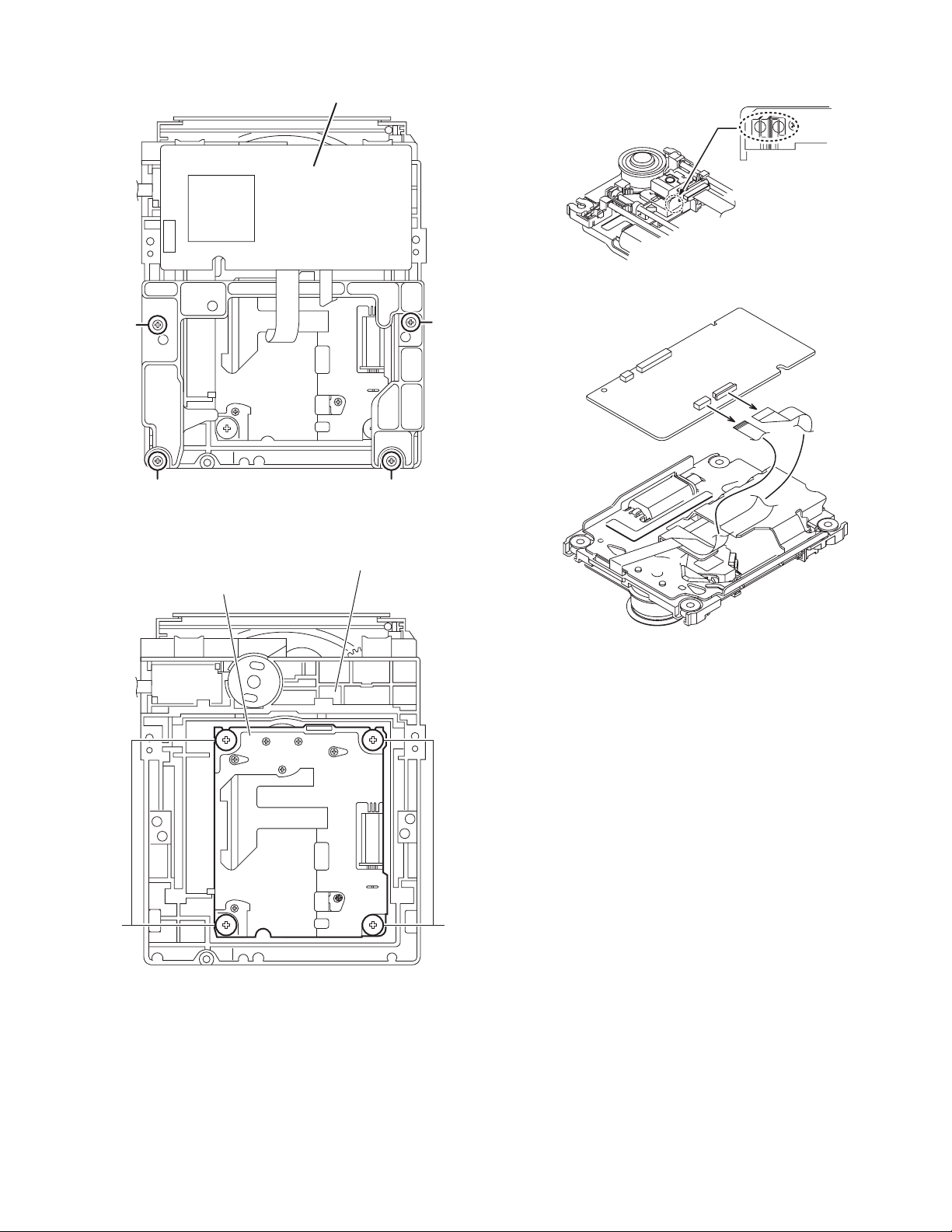
DVD module board
Solder short land section
Fig.5
C
C
CC
Fig.3
DVD mechanism assembly
Traverse mechanism assembly
DVD module board
CN101
CN201
Fig.6
DD
Fig.4
(No.MB638)1-21
Page 22
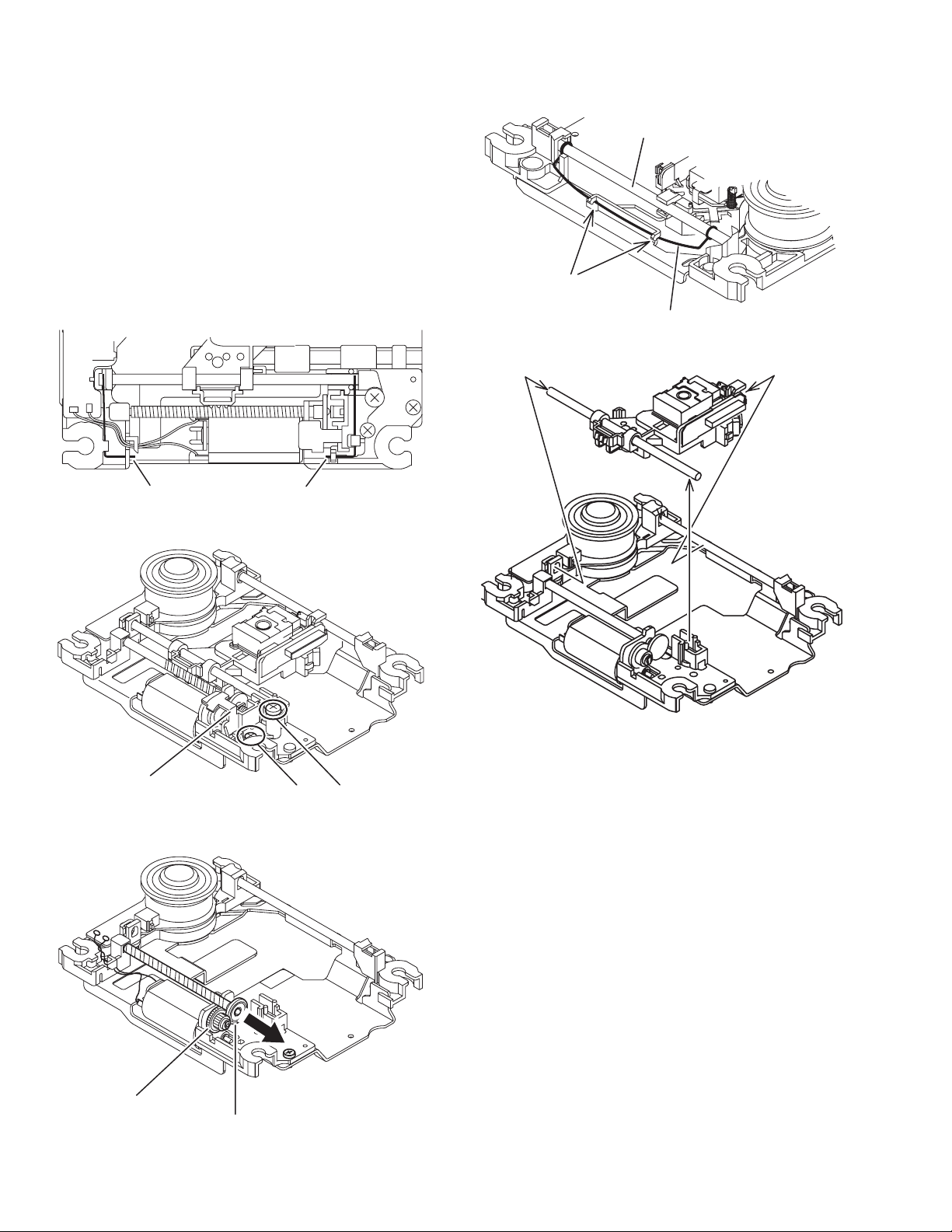
3.2.2 Removing the pickup assembly
(See Fig.7 to 11)
(1) Remove the two rod springs pressing the guide shaft. (See
Fig.7)
(2) Remove the screw E and F attaching the spring holder.
(See Fig.8)
(3) Remove the read screw from traverse mechanism assem-
bly. (See Fig.9)
Caution:
When remove the lead screw, do not loss the middle
gear. (See Fig.10 and 11)
(4) Remove the bar spring pressing the shaft. (See Fig.10)
(5) Take out the pickup assembly from traverse mechanism
chassis by order. (See Fig.11)
(SHAFT)
(T.TABLE)
HOOK
(BAR SPRING)
Fig.10
ROD SPRING ROD SPRING
Fig.7
Spring holder
Fig.8
order 2
order 3
order 1
Fig.11
EF
Middle gear
1-22 (No.MB638)
Lead screw
Fig.9
Page 23
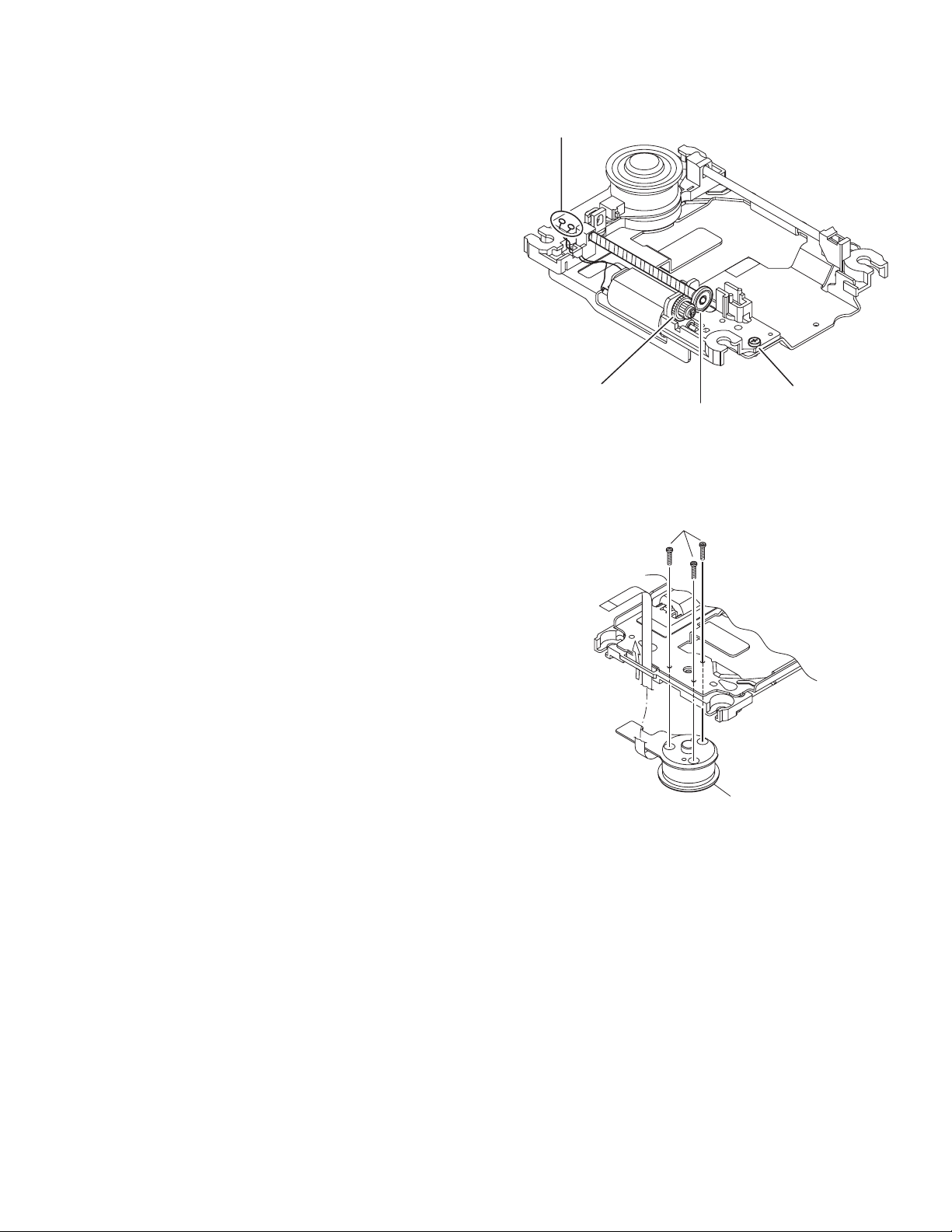
3.2.3 Removing the feed motor assembly
(See Fig.12)
(1) Remove the one screw G attaching the feed motor assem-
bly.
(2) Remove the feed motor wires from solder part of spindle
motor board.
Splder part
3.2.4 Removing the spindle motor assembly
(See Fig.13)
(1) Remove the three screws H attaching the spindle motor
from spindle motor board.
Middle gear
Lead screw
Fig.12
H
Spindle motor
Fig.13
G
(No.MB638)1-23
Page 24
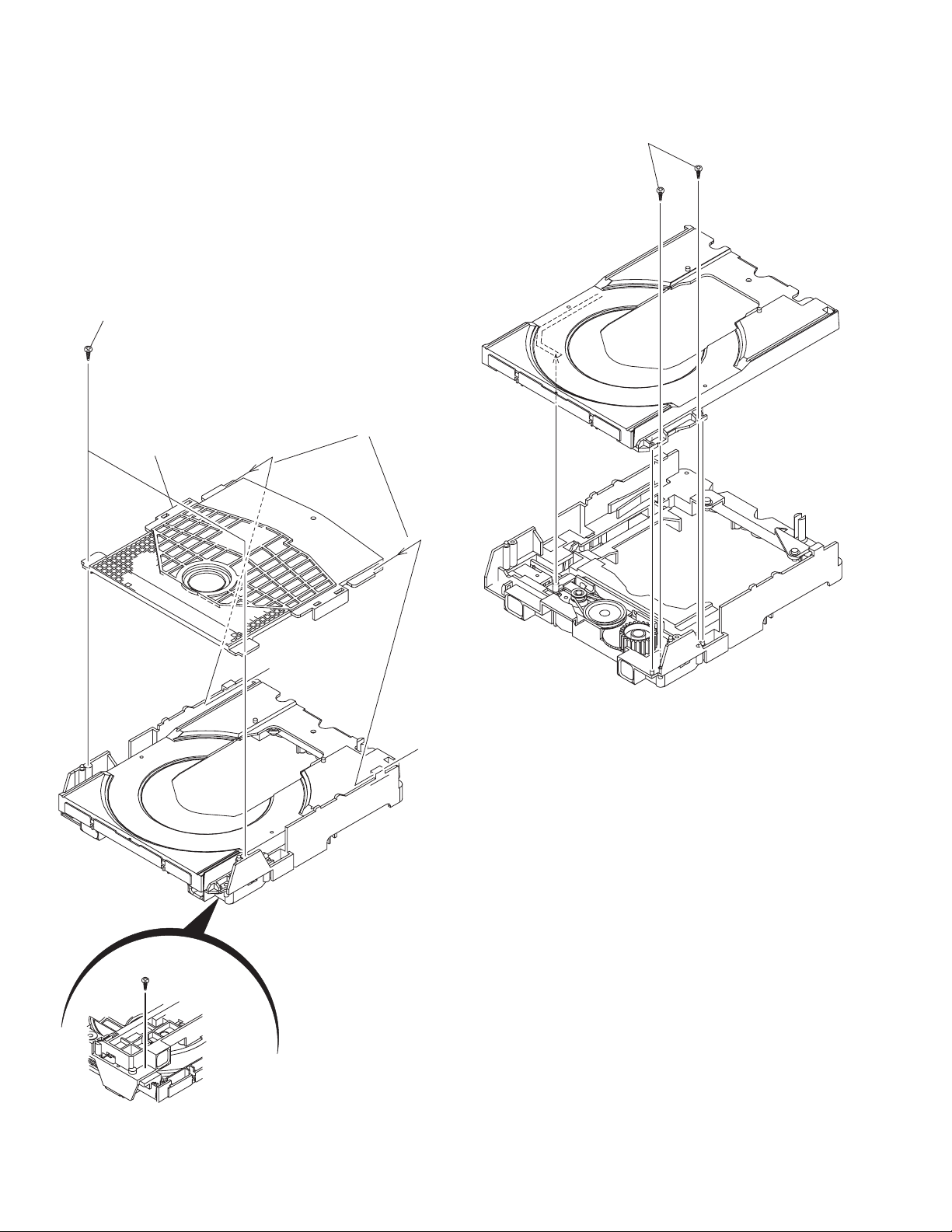
3.2.5 Removing the tray assembly
(See Fig.14 & 15)
(1) Remove the two screws J attaching the clamper base.
(See Fig.14)
(2) Remove the one screw K attaching the shaft guide from
bottom side. (See Fig.14)
(3) Remove the two screws L attaching the shaft guide from
top side. (See Fig.15)
Caution:
When attach the tray assembly, boss of loading sub assembly
should attach to guide of bottom side at tray assembly. (See
Fig.15)
J
order 1
order 2
clamper base
L
K
Fig.15
[bottom side]
Fig.14
1-24 (No.MB638)
Page 25

SECTION 4
ADJUSTMENT
4.1 ATTENTION IN SERVICE OF DVD SECTION
(1) When pickup, Flash ROM ,DVD module board were changed, initialize EEPROM by all means.
(2) When full initialization was executed, execute learning with a DVD test disc by all means.
Test disc : VT-501, VT-502
Learning method : It is adjusted automatically by normal playback of a DVD disc.
4.2 DVD TEST MODE
4.2.1 Content of correspondence TEST MODE
(1) Version, Region, Learning status check mode
(2) NORMAL initialize, FULL initialize
(3) Device key write(CPPM, CPRM)
(4) Device key checksum indication mode
(5) Micon version indication mode
(6) FL all on mode
(7) FRONT END check mode
4.2.2 Mode transition
TEST MODE into the press [SOURC key] and [POWER key] together of main body, connect the AC power.
After into the TEST MODE, mode select by [MENU key].
SOURCE+POWER+AC
MENU key
Version, Region, Learning
status indication mode
F.SKIP key 4sec
SOURCE key B.SKIP
long press
Device key
checksum
MENU key MENU key MENU key
Micon version
indication mode
FL all on
mode
mode
FRONT END
check mode
NORMAL
initialize
FULL
initialize
Device key
write
MENU key
MENU key
4.2.3 Processing details
The communication of operated FL(LCD) display and DVD back end microcomputer is shown as follows.
*It is assumed to be OK to differ from the content of the specification because the number of digits is different according to the set for
the FL(LCD) display.
*It is assumed to be OK to differ from the content of the specification because it also has the relation between arrangement and presence by the set also for the key.
STEP Operation Movement Remarks
1
AC is pulled out, and
double press [SOURCE]
and [POWER] key of the
main body
2 Keep step 1, connect AC
Version, Region, Learning
status indication mode
Power on by test mode,
version indication to FL
FL(LCD)indication
132465798
JC#
T
10 1211 13
Version indication
The display to the version code is as
follows.
0x01:JC 0x02:1U 0x03:D 0x04:E
0x05:2U 0x06:3U 0x07:UB 0x08:UT
0x09:4U 0x0a:UY 0x0b:EE 0x0c:UF
Region indication (# part)
Learning from the back end is displayed
in the 11th digit and the 12th digit
of the FL display.
Blank indication at 0xFF
Study status (11th column)
0x07: BCA CHECK OK incomplete
DVD learning incomplete
CD learning incomplete (indication 7)
0x06: BCA CHECK OK incomplete
DVD learning complete
CD learning incomplete (indication 6)
0x05: BCA CHECK OK incomplete
DVD learning incomplete
CD learning complete (indication 5)
(No.MB638)1-25
Page 26

STEP Operation Movement Remarks
132465798
FL(LCD)indication
10 1211 13
0x04: BCA CHECK OK incomplete
DVD learning complete
CD leaning complete (indication 4)
0x03: BCA CHECK OK complete
DVD learning incomplete
CD learning incomplete (indication 3)
0x02: BCA CHECK OK complete
DVD learning complete
CD learning incomplete (indication 2)
0x01: BCA CHECK OK complete
DVD learning incomplete
CD learning complete (indication 1)
0x00: BCA CHECK OK complete
DVD learning complete
CD learning complete (indication 0)
(BCA READ CHECK result is only BCA
READ OK, it to complete)
Initialization status (12th column)
0X03: FULL initialize complete
(indication 3)
0x00: NORMAL initialize complete
(indication 0)
0xFF: Initialize incomplete
(blank indication)
Press a [SOURCE] key
of the main body.
NORMAL initialize
Continue pressing a
[F.SKIP] key of the main
body.(4sec)
FULL initialize
3
Press a [MENU] key of
the remote controller.
Press a [MENU] key of
the remote controller.
4 Press a [MENU] key of
the remote controller.
Press a [MENU] key of
5 FL all on mode
the remote controller.
Press a [MENU] key of
6
the remote controller.
Press a [1] key of the 10
key on remote controller
Press a [2] key of the 10
key on remote controller
Press a [3] key of the 10
key on remote controller
DEVICE CHECKSUM
indication mode
Indicate the CHECKSUM
of the Device key to FL
(4 byte)
Micon version indication
mode
Indicate the version to FL
All FL and all LED to ON
FRONT END check mode
Indicate the front end check
mode to FL
Disc startup and through
playback
(Playback starts from the
start position)
Presence of WOBBLE
0:WOBBLE_NO_CHECK
(un check)
1:WOBBLE_PRESS_MEDIA
(press)
2:WOBBLE_MINUS_MEDIA
(DVD-R/-RW media)
3:WOBBLE_PLUS_MEDIA
(DVD+R/+RW media)
Port check mode
(TRACK,INDEX,DEMP,
COPY)
1:INDEX Port = High
2:TRACK Port = High
3:COPY Port = High
4:DEMP Port = High
JC#T
JC#
T
bbcccac
CEHCK
CEHCK
The AVC protocol is returned from
high speed to normal speed.
(Return it to the normal mode when
coming off the TEST mode. )
Indicate CHECKSUM to FL
,,,
,,,
,,,
bb : Syscon Version
a : Syscon Romcorr Version
cccc: DVD Back end Version
Upper : 0
Lower : WOBBLE detection result
Upper : 0x01-0x04(check port number)
Lower : 0
: CPPM
: CPRM
: HDCP
1-26 (No.MB638)
Page 27

STEP Operation Movement Remarks
Press a [4] key of the 10
key on remote controller
Press a [5] key of the 10
key on remote controller
Press a [6] key of the 10
key on remote controller
Press a [8] key of the 10
key on remote controller
Press a [9] key of the 10
key on remote controller
Press a [10] key of the 10
key on remote controller
Press a [0] key of the 10
key on remote controller
Press a [ 10] key of the
10key on remote controller
Press a [STOP] key of
the main body or remote
controller
Press a [OPEN/CLOSE]
key of the main body or
remote controller
Press a [PLAY] key of
the main body or remote
controller
Press a [MENU] key of
7
the remote controller
Press a [POWER] key of
the main body
CD_LD lights and laser
current is displayed
DVD_LD lights and laser
current is displayed
DVD_SL x1 jitter
measurement mode
Content of BACKUP
memory(0x00-0x63)
indication (FWD)
Temperature sensor
(AD value) indication
DVD-DL(parallel,opposite)
Search & jitter
measurement of the
specified position of
DVD-SL
MONITOR output switch
1: SRV_MONI_CIRC
2: SRV_MONI_SERVO
3-5: SRV_MONI
_ANALOG
6-7: SRV_MONI_DRC
8-11: SRV_MONI
_SERVO_JIG
12: SRV_MONI
_DEFAULT
BCA READ CHECK
0:During BCA READ
1:BCA READ OK
2:BCA SEEK ERROR
3:BCA READ ERROR
4:SPINUP adjust ERROR
Disc stop, LD-OFF
Tray Open/Close
Disc playback
Back to STEP 2
Release the TEST MODE
132465798
FL(LCD)indication
10 1211 13
Upper : Laser current value
(BACKUP value,Real measured value)
Lower : 0
Upper : Laser current value
(BACKUP value,Real measured value)
Lower : 0
Upper : Laser current value
(BACKUP value,Real measured value)
Lower : Real measured value
Upper Byte1 : Display option
0x00 : BACKUP area
0xFF : permanent area
Upper Byte2 : BACKUP memory address
(0x00-0x63)
Lower : Content of BACKUP memory
Upper : 0
Lower : Temperature sensor value
Upper : 0x00-0x06(measure at VT501)
Lower : Jitter value
Upper : 0x00-0x0C
Lower : 0
CEHCK
Upper:Laser current value
(BACKUP value, Real measured value)
Lower:Jitter value
Release at each step
*1 Mode toggle done by press [MENU] key.
*2 STEP3 are only for DVD-AUDIO or VR correspondence model.
(No.MB638)1-27
Page 28

4.3 KEY special mode
MODE NAME OPERATIONSTATUS FUNCTION
TUNER 9K/10kHz
select (U ver)
P. O F F
P. O F F
TRAY LOCK
DVD TEST mode
XM Diagnostic mode
P. O F F
AC off
P.OFF at XM
4.4 REMOCON KEY special mode
Change to 9kHz step by
press and hold [+] key,
then press [|<<] key.
Change to 10kHz step by
press and hold [+] key,
then press [>>|] key.
Press and hold [+] key,
then press [EJECT] key
Press and hold
[SOURCE] and [POWER]
key, and connecto to AC.
Press and hold [-] key,
and press [POWER] key
TUNER AM 9kHz/10kHz step select.
Indicate "9k STEP", "10k STEP".
Do the TRAY LOCK mode select. Done the tempolary
P.ON process, select the "LOCKED" and "UNLOCKED"
(Do no done the P.ON process).
Ended the transitory display (2 seconds) return to
P.OFF mode.‘
When press the [EJECT] key at LOCK mode, at P.OFF
status do templary P.ON process then the transitory display
(2 seconds) the "LOCKED", at P.ON status do the transitory
display (2 seconds) the "LOCKED".
DVD backend started by TEST mode.
Internal TEST mode process is refer the spec.
Into the XM Diagnostic mode.
MODE NAME OPERATIONCODE FUNCTION
COLD START
[STOP] +
[POWER] + [0]
2 times input at P.OFF
When Fix by 2 times input, do the templary P.ON process
then indicate "COLD SET" by transitory (2 seconds).
Ended the indication, change to P.OFF mode.
FL all ON
Write the preset
frequency
[STOP] +
[POWER] + [1]
Input at P.ON
Write the preset frequency, LED all on check (each 300ms),
FL all on
LED on order : STANDBY -> ILLUMI ->
Volume control by [VOL+] and [VOL-] key of the remote
controller, it should high speed mode until next POWER OFF.
Version indication
[STOP] +
[POWER] + [10]
Input at P.ON
Syscon version indication -> Unit version indication
-> destination -> Chip select transitory indication (5 seconds).
Syscon version: "SC ## $$"
(## : Syscon version, $ : Syscon romcollection)
Unit version: "BE %%%%" (%%%% : Unit version)
Destination, Chip select: "$$ %% KX"
($$ : Syscon destination, %% : "D4" or "D5" or "D6" or "D7"
or "D8", K : KARAOKE, X : XM READY)
XM TEST MODE
[STOP] +
[POWER] + [5]
Input at XM SOURCE
XM ready test mode
TEST TONE (L/R 1 kHz) output
1-28 (No.MB638)
Page 29

4.5 TH-D SPECIAL MODE Ver 0.2
POWER EJECT B.SKIP F.SKIP SOURCE
MODE OPERATIONSET STATUS KEY1
DVD TEST MODE
TRAY LOCK
TUNE 9K
TUNE 10K
NORMAL INITIALIZE
FULL INITIALIZE
This service manual does not describe TROUBLESHOOTING.
AC OFF SOURCE
STANDBY
STANDBY
STANDBY
TEST MODE
TEST MODE
Press and keep [+] key
Press and keep [+] key
Press and keep [+] key
SOURCE
F.SKIP
SECTION 5
TROUBLESHOOTING
KEY2
POWER
EJECT
B.SKIP
F.SKIP
+
AC IN
Press
Press 4 seconds.
(No.MB638)1-29
Page 30

Victor company of Japan, Limited
Audio/Video Systems category 10-1,1chome,Ohwatari-machi,Maebashi-city,371-8543,Japan
(No.MB638)
Printed in Japan
VPT
Page 31

PARTS LIST
TH-D7B,TH-D7E,TH-D7EN
TH-D7EV,TH-D7A,TH-D7US
TH-D7UX,TH-D7UG
* All printed circuit boards and its assemblies are not available as service parts.
MB638
- Contents -
Exploded view of general assembly and parts list (Block No.M1)
DVD mechanism assembly and parts list (Block No.MJ)
DVD loading base assembly and parts list (Block No.MN)
Electrical parts list (Block No.01~07)
Packing materials and accessories parts list (Block No.M3)
3- 2
3- 6
3- 8
3-10
3-24
3-1
Page 32

Exploded view of general assembly and parts list
B
2
6
Block No.
M
M
1
M
71
USB board
68
4
38
H
33
HDMI switch board
69
70
93
67
42
c
46
n
91
z
27
m
90
G
23
88
69
D
A
46
89
f
95
LED board
12
b
12
83
1
12
71
12
81
u
82
9
u
US,UX,
11
11
5
11
96
p
UG ver.
102
Touch board
10
12
12
12
25
12
12
t
jj
12
12
p
q
13
3
VFD board
C
b
22
28
c
85
d
94
8
15
J
12
11
F
J
6
7
Head phone board
t
12
2
15
26
US,UX,UG ver.
q
41
iPod board
d
40
27
8
3-2
98
US,UX,UG ver.
J
99
Mic board
Page 33

US,UX,UG ver.
M
M
60
switch board
z
m
88
89
95
25
12
12
12
t
d
Pod board
d
91
b
23
27
H
32
62
61
100
47
G
22
28
C
85
w
Fuse board
E
63
101
24
74
34
j
24
k
Digital in Jack board
27
31
73
v
92
a
31
G
28
25
28
v
66
25
f
m
n
c
e
86
87
j
z
45
B
AMP board
a
Main board
18
44
US,UX,
UG ver.
k
H
27
48
57
49
55
58
50
s
52
B,E,EN,EV ver.
59
51
53
56
47
54
97
64
35
E
63
30
29
jj
h
19
84
44
d
D
28
r
16
17
94
39
65
27
72
43
36
43
79
76
77
g
27
s
r
w
E
Power board
27
43
C
20
80
h
21
40
27
e
B
14
15
A
F
15
g
75
37
36
65
78
The parts without symbol number are not service.
US,UX,
UG ver.
103
3-3
Page 34

General Assembly
Symbol No. Part No. Part Name Description Local
1 GN10122-003A FRONT PANEL
2 GN10123-026A ORNAMENT B,E,EN,EV
2 GN10123-028A ORNAMENT A
2 GN10123-027A ORNAMENT US,UX,UG
3 GN20231-001A PUSH BUTTON
4 GN20233-005A WINDOW SCREEN
5 LV42851-012A FL SCREEN
6 GN30223-003A LENS
7 LV30227-0A7A SPACER
8 QYSDSF2608ZA TAP SCREW M2.6 x 8mm(x2) B,E,EN,EV,A
8 QYSDSF2608ZA TAP SCREW M2.6 x 8mm(x3) US,UX,UG
9 GN40140-001A LENS(DVD)
10 GN40152-001A SENSOR SPACER
11 QYSDSF2608ZA TAP SCREW M2.6 x 8mm(x4)
12 QYSDSF2608ZA TAP SCREW M2.6 x 8mm(x15)
13 QYSDSG2606EA TAP SCREW M2.6 x 6mm(x3)
14 GN10124-003A BOTTOM CHASSIS
15 LV40301-002A FELT SPACER (x4)
16 GN20234-201A HEAT SINK
17 LV30227-0A1A SPACER (x2)
18 GN20235-002A BRACKET(IC)
19 GN20236-001A BRACKET(H.SINK)
20 GN30224-001A BRACKET(POWER)
21 GN30228-002A POWER BRACKT
22 GN30225-201A BRACKET(FAN)
23 GV30349-025A SPACER
24 LV30226-037A SPACER (x2)
25 GV30349-025A SPACER (x3)
26 QYSDSG3008ZA TAP SCREW M3 x 8mm(x3)
27 LV43451-002A SPECIAL SCREW (x10)
28 QYSDSG3006EA TAP SCREW M3 x 6mm(x5)
29 QYSBSG3010EA TAP SCREW M3 x 10mm(x2)
30 GV30349-025A SPACER
31 QYSBSG3020ZA TAP SCREW M3 x 20mm(x3)
32 QYSBSGY3008EA TAP SCREW M3 x 8mm US,UX,UG
33 QYSDSG3008ZA TAP SCREW M3 x 8mm
34 QYSBSG3030ZA TAP SCREW M3 x 30mm(x2)
35 QYSBSG3010ZA TAP SCREW M3 x 10mm(x3)
36 QYSDSG3008ZA TAP SCREW M3 x 8mm(x2)
37 QYWBS326505ZA WASHER 6.5mm/3.2mm x 0.5mm
38 GN30227-001A HDMI BRAKET B
39 GN40145-001A BRACKET (x2)
40 GN40146-001A BRACKET
41 QYSDSG3008ZA TAP SCREW M3 x 8mm
42 QYSBSG3016EA TAP SCREW M3 x 16mm
43 LV44937-001A SPACER (x4)
44 QYSDSTL4008EA TAP SCREW M4 x 8mm(x4)
45 LV30227-092A SPACER
46 VYSH101-009 SPACER (x3)
47 GN20237-034A REAR PANEL B,E,EN,EV
47 GN20237-032A REAR PANEL A
47 GN20237-040A REAR PANEL US,UX,UG
48 QYSBSGY3008EA TAP SCREW M3 x 8mm
49 QYSBSGY3008EA TAP SCREW M3 x 8mm
50 QYSBSGY3008EA TAP SCREW M3 x 8mm
51 QYSBSGY3008EA TAP SCREW M3 x 8mm
52 QYSBSGY3008EA TAP SCREW M3 x 8mm(x2)
53 QYSBSGY3008EA TAP SCREW M3 x 8mm
54 QYSBSGY3008EA TAP SCREW M3 x 8mm B,E,EN,EV,A
55 QYSBST3006EA TAP SCREW M3 x 6mm(x3)
56 QYSBSGY3008EA TAP SCREW M3 x 8mm(x2)
57 QYSBSGY3008EA TAP SCREW M3 x 8mm(x2)
58 QYSBSGY3008EA TAP SCREW M3 x 8mm
59 QYSBSGY3008EA TAP SCREW M3 x 8mm(x2) B,E,EN,EV
60 QMPN410-200-JD POWER CORD 2m BLACK B
60 QMPK200-200-JD POWER CORD 2m BLACK E,EN,EV,US,UX,UG
60 QMPG150-244-JC POWER CORD(AST) 2.44m BLACK A
61 QQR0491-002 FERRITE CORE TDK (BLACK) B,E,EN,EV
62 QZW0033-001 STRAIN RELIEF
63 LV30227-093A SPACER (x2)
64 LV30227-0A2A SPACER
65 LV30225-011A SPACER (x2)
66 LV30227-0A4A SPACER
67 GN30220-001A FITTING
Block No. [M][1][M][M]
3-4
Page 35

Symbol No. Part No. Part Name Description Local
68 GN10125-003A/S/ METAL COVER
69 QYSBSGY3008EA TAP SCREW M3 x 8mm(x4)
70 LV44339-001A SPECIAL SCREW
71 E406308-006 SPECIAL SCREW (x2)
72 QQT0539-002 POWER TRANSF B,E,EN,EV,A
72 QQT0539-003 POWER TRANSF US,UX,UG
73 QAU0473-001 TUNER B,E,EN,EV
73 QAU0492-001 TUNER A,US,UX,UG
74 QAR0377-001 COOLING FAN
75 QMF51W2-2R5-J8 FUSE 2.5A AC250V B,E,EN,EV,A
75 QMF51W2-6R3-J8 FUSE 6.3A AC250V US,UX,UG
76 QMF51W2-6R3-J8 FUSE 6.3A AC250V
77 QMF51W2-6R3-J8 FUSE 6.3A AC250V
78 QYSDSG3008ZA TAP SCREW M3 x 8mm(x2)
79 QMF51W2-2R0-J8 FUSE 2A AC250V
80 QMF51W2-2R0-J8 FUSE 2A AC250V
81 LV30227-0A5A SPACER
82 GN40141-001A LED HOLDER
83 GN40141-001A LED HOLDER
84 QYSBST3008ZA TAP SCREW M3 x 8mm
85 QYSBST3008ZA TAP SCREW M3 x 8mm
86 QYSDSG3008ZA TAP SCREW M3 x 8mm
87 QYSBST3008ZA TAP SCREW M3 x 8mm
88 QUR110-1809AE-E FFC WIRE
89 QUR110-2606AE-E FFC WIRE
90 QUR110-0907AE-E FFC WIRE
91 QUR310-0815AE-E FFC WIRE
92 QUQU12-1510AJ-E FFC WIRE 15pin 10cm B,E,EN,EV
92 QUQU12-1110AJ-E FFC WIRE 11pin 10cm A,US,UX,UG
93 QUR110-0512AE-E FFC WIRE
94 QUR110-1310AE-E FFC WIRE
95 QUR110-2918AE-E FFC WIRE
96 QUR110-0906AE-E FFC WIRE
97 LV37706-020A RATING LABEL B,E,EN,EV
97 LV37706-021A RATING LABEL A
97 LV37706-012A RATING LABEL US
97 LV37706-014A RATING LABEL UX
97 LV37706-013A RATING LABEL UG
98 GN30054-003A VOLUME KNOB US,UX,UG
99 LV30226-041A SPACER (x3) US,UX,UG
100 QYSBSGY3008EA TAP SCREW M3 x 8mm(x2) US,UX,UG
101 QMF51W2-2R5-J8 FUSE 2.5A AC250V US,UX,UG
102 QUR110-0710AE-E FFC WIRE US,UX,UG
103 QYSBST3008ZA TAP SCREW M3 x 8mm US,UX,UG
3-5
Page 36

DVD mechanism assembly and parts list
Block No.
M
J
M
M
Grease
=JVG-31N
=JVS-1003
=1401C
< Back side >
29
28
25
31
24
31
30
26
27
FXL-D10-11M
10
31
20
23
30
31
22
18
15
21
16
17
14
7.0mm
+
0.2mm
-
7
6
13
3
9
3
2
1
11
12
8
5
4
The parts without symbol number are not service.
3-6
Page 37

DVD mechanism
Symbol No. Part No. Part Name Description Local
1 LV22234-003A T.M.CHASSIS
2 LV22235-001A SPINDLE BASE
3 QYSDST2005ZA TAP SCREW M2 x 5mm(x2)
4 LV36555-001A G.S.HOLDER
5 QYSDST2005ZA TAP SCREW M2 x 5mm
6 LV44041-002A GUIDE SHAFT
7 LV44479-001A BAR SPRING
8 LV22236-001A FEED HOLDER
9 QAR0165-001 FEED MOTOR 5.0V DC
10 LV30225-0X5A SPACER (x2)
11 LV36557-001A F.M.GEAR
12 QYSPSPT2030MA SCREW M2 x 3mm
13 QYSDST2005ZA TAP SCREW M2 x 5mm
14 QAL0786-004 P.UP
15 LV22237-001A RACK ARM
16 LV36560-001A RACK ARM SPRING
17 QYSPSFU1740ZA TAP SCREW M1.7 x 4mm(x2)
18 QUQK05-2420AC-E FFC WIRE 24pin 20cm
20 LV44041-002A GUIDE SHAFT
21 LV36559-001A L.S.GEAR
22 LV41517-003A LEAD SCREW
23 LV36558-001A MIDDLE GEAR
24 LV36556-001A SPRING HOLDER
25 LV44623-001A COMP.SPRING
26 QYSDST2005ZA TAP SCREW M2 x 5mm
27 QYSDST2616MA TAP SCREW M2.6 x 16mm
28 QAR0387-001 S.MOTOR
29 QYSPSPU1775ZA SCREW M1.7 x 7.5mm(x3)
30 LV44042-001A ROD SPRING (x2)
31 LV44046-001A ADJUST SCREW (x4)
Block No. [M][J][M][M]
3-7
Page 38

DVD loading base assembly and parts list
Grease
JVS-1003
CFD-4007ZY2
21
20
19
16
h
FMU-MB5-21M
33
15
Block No.
N
M
M
M
2
3
14
12
1
h
< Back side >
13
DVD loading switch board
f
16
18
j
11
9
10
0.10mm
4
7
8
6
7.75mm
< In side >
Backside
5
j
d
c
DVD module board
32
31
32
3-8
24
23
g
e
A
24
B
23
26
A
k
B
24
22
23
30
c
k
27
29
25
24
f
d
30
23
g
e
The parts without symbol number are not service.
Page 39

DVD loading base
Symbol No. Part No. Part Name Description Local
1 LV11065-010A LOADER SUB ASSY
2 E407140-001SS C.D ROLLER
3 E407149-001SS RUBBER TUBE
4 LV10979-003A TRAY
5 LV35499-003A SHAFT GUIDE
6 LV44022-001A SHAFT
7 QYSSSF2008ZA TAP SCREW M2 x 8mm
8 QYSDSF2008ZA TAP SCREW M2 x 8mm(x2)
9 LV41741-004A SPECIAL SCREW
10 QAR0197-001 MOTOR 2.0V DC
10 or QAR0450-001 MOTOR
11 LV43844-002A MOTOR PULLEY
12 QYSPSPU1730ZA SCREW M1.7 x 3mm(x2)
13 QYSDSF2008ZA TAP SCREW M2 x 8mm
14 LV43974-001A BELT
15 LV21852-003A CLAMPER BASE
16 QYSDSF2008ZA TAP SCREW M2 x 8mm(x2)
18 LV35056-002A DVD CLAMPER
19 LV42930-003A P.C.MAGNET
19 or LV41118-003A MAGNET
20 LV43848-001A YOKE
21 LE40906-002A SPECIAL SCREW
22 FXL-D10-11M SINGLE DVD TRAM
23 LV44043-001A INSULATOR (x4)
24 LV44044-001A SPECIAL SCREW (x4)
25 LV44007-001A TAPE
26 LV44007-003A TAPE
27 GN30226-002A HDMI BRAKET A
29 GN20232-002A FITTING
30 QYSBSF2608ZA TAP SCREW M2.6 x 8mm(x3)
31 QYSBSFG2606ZA TAP SCREW M2.6 x 6mm
32 GV30349-025A SPACER (x2)
33 LV44603-003A LASER CAUTION
Block No. [M][N][M][M]
3-9
Page 40

Electrical parts list
Main board
Block No. [0][1]
Symbol No.
IC161 PQ1CG21H2FZ IC Regulator
IC162 KIA7806API IC
IC181 KIA7810API IC
IC211 MN101C49KAG1 IC(MCU)
IC212 TC74VHCT08AFT-X IC(DIGITAL)
IC241 BR24L08F-W-X IC(DIGITAL)
IC261 LB1641 IC
IC291 MM1565AF-X IC
IC301 NJM4565M-WE IC
IC321 R2S15902FP IC
IC331 NJM4565M-WE IC
IC351 NJM4565M-WE IC
IC361 TC74VHCU04FT-X IC(DIGITAL)
IC362 TC74VHC00FT-X IC
IC381 TC4053BFT-X IC
IC382 TC4053BFT-X IC
IC411 MM1233XF-X IC
IC412 MM1233XF-X IC
IC421 MM1623XF-X IC
IC461 TC4066BFT-X IC(DIGITAL) B,E,EN,
IC641 NJM4565M-WE IC
IC642 NJM4565M-WE IC
Q1611 RT1P141C-X DIGI TRANSISTOR
Q1701 KTB772/Y/ TRANSISTOR
Q1702 2SC3928A/QR/-X TRANSISTOR
Q1901 RT1N241C-X DIGI TRANSISTOR
Q1902 RT1P141C-X DIGI TRANSISTOR
Q1903 KTC3203/OY/-T TRANSISTOR
Q1904 RT1N141C-X DIGI TRANSISTOR
Q1905 RT1N141C-X DIGI TRANSISTOR
Q2001 RT1N141C-X DIGI TRANSISTOR
Q2002 RT1N141C-X DIGI TRANSISTOR
Q2101 RT1N140C-X DIGI TRANSISTOR
Q2201 RT1N140C-X DIGI TRANSISTOR
Q2301 RT1N430C-X TRANSISTOR
Q2701 KTA1271/OY/-T TRANSISTOR
Q2702 2SC3928A/QR/-X TRANSISTOR
Q3001 IMX9-W TRANSISTOR
Q3002 RT1P431C-X DIGI TRANSISTOR
Q3401 RT1P141C-X DIGI TRANSISTOR
Q3501 IMX9-W TRANSISTOR
Q3502 IMX9-W TRANSISTOR
Q3503 IMX9-W TRANSISTOR
Q3531 2SC3928A/QR/-X TRANSISTOR
Q3532 RT1N141C-X DIGI TRANSISTOR
Q3541 2SC3928A/QR/-X TRANSISTOR
Q4521 RT1P141C-X DIGI TRANSISTOR B,E,EN,
Q4522 RT1N141C-X DIGI TRANSISTOR B,E,EN,
Q4523 RT1P141C-X DIGI TRANSISTOR B,E,EN,
Q4524 RT1P141C-X DIGI TRANSISTOR B,E,EN,
Q4525 RT1N141C-X DIGI TRANSISTOR B,E,EN,
Q4601 RT1N441C-X TRANSISTOR B,E,EN,
Q6401 RT1N431C-X TRANSISTOR
Q6402 RT3CLLM/EF/-X PAIR TRANSISTOR
Q6501 RT1N140C-X DIGI TRANSISTOR
Q6601 RT1N140C-X DIGI TRANSISTOR
Q6701 RT1N140C-X DIGI TRANSISTOR
Q6801 RT1N144C-X DIGI TRANSISTOR
Q6802 RT1N144C-X DIGI TRANSISTOR
Q6803 RT1N144C-X DIGI TRANSISTOR
D1611 EC30HA04-X SB DIODE
D1612 MTZJ6.2B-T2 Z DIODE
D1613 2A02-M DIODE
D1614 2A02-M DIODE
Part No. Part Name Description Local
EV
EV
EV
EV
EV
EV
EV
Symbol No.
D1615 1N4003S-T5 SI DIODE
D1621 1N4003S-T5 SI DIODE B,E,EN,
D1622 1N4003S-T5 SI DIODE B,E,EN,
D1624 1N4003S-T5 SI DIODE B,E,EN,
D1625 2A02-M DIODE US,UX,
D1626 2A02-M DIODE US,UX,
D1627 2A02-M DIODE US,UX,
D1628 1N4003S-T5 SI DIODE US,UX,
D1701 UDZW7.5B-X Z DIODE
D1801 MTZJ12B-T2 Z DIODE B,E,EN,
D1801 MTZJ12C-T2 Z DIODE A,US,
D1901 UDZW12B-X Z DIODE B,E,EN,
D1901 UDZW13B-X Z DIODE A,US,
D1902 UDZW6.8B-X Z DIODE
D2001 1N4003S-T5 SI DIODE
D2002 UDZW7.5B-X Z DIODE
D2003 MA152WA-X DIODE
D2004 1SS355W-X DIODE
D2005 MA152WA-X DIODE
D2006 UDZW3.9B-X Z DIODE
D2007 1SS355W-X DIODE
D2101 1SS355W-X DIODE
D2102 1SS355W-X DIODE
D2103 1SS355W-X DIODE
D2104 1SS355W-X DIODE
D2201 UDZW3.9B-X Z DIODE
D2301 1SS355W-X DIODE
D2601 UDZW4.7B-X Z DIODE
D2701 1SS355W-X DIODE
D2702 UDZW6.8B-X Z DIODE
D2703 UDZW5.1B-X SB DIODE B,E,EN,
D3531 1SS355W-X DIODE
D3541 1SS355W-X DIODE
D6801 HL-PC3216B-X LED
D6802 HL-PC3216B-X LED
D6803 HL-PC3216B-X LED
C1501 QETM1EM-828 E CAPACITOR 8200uF 25V M
C1612 NCB31CK-104X C CAPACITOR 0.1uF 16V K
C1613 QEZ0654-477Z E CAPACITOR 470uF 10V M
C1614 NCB31CK-104X C CAPACITOR 0.1uF 16V K
C1621 NCB31CK-104X C CAPACITOR 0.1uF 16V K
C1622 QETN1CM-107Z E CAPACITOR 100uF 16V M
C1623 NCB31CK-104X C CAPACITOR 0.1uF 16V K
C1624 QETN1AM-477Z E CAPACITOR 470uF 10V M
C1701 QETN1HM-106Z E CAPACITOR 10uF 50V M
C1702 QETN1CM-107Z E CAPACITOR 100uF 16V M
C1801 NCB31CK-104X C CAPACITOR 0.1uF 16V K
C1802 QETN1CM-107Z E CAPACITOR 100uF 16V M
C1803 NCB31CK-104X C CAPACITOR 0.1uF 16V K
C1804 QETN1EM-107Z E CAPACITOR 100uF 25V M
C1901 QETN1CM-107Z E CAPACITOR 100uF 16V M
C1902 QETN1EM-476Z E CAPACITOR 47uF 25V M
C2101 NDC31HJ-220X C CAPACITOR 22pF 50V J
C2102 NDC31HJ-220X C CAPACITOR 22pF 50V J
C2103 NCB31CK-104X C CAPACITOR 0.1uF 16V K
C2104 NCB31CK-104X C CAPACITOR 0.1uF 16V K
C2105 NCB31CK-104X C CAPACITOR 0.1uF 16V K
C2201 QETN1AM-108Z E CAPACITOR 1000uF 10V M
C2301 QETN1HM-106Z E CAPACITOR 10uF 50V M
C2302 QETN1HM-226Z E CAPACITOR 22uF 50V M
C2303 NCB31HK-102X C CAPACITOR 1000pF 50V K
C2401 QETN1CM-107Z E CAPACITOR 100uF 16V M
C2402 NCF31HZ-103X C CAPACITOR 0.01uF 50V Z
C2601 NCB31CK-104X C CAPACITOR 0.1uF 16V K
Part No. Part Name Description Local
EV,A
EV,A
EV,A
UG
UG
UG
UG
EV
UX,UG
EV
UX,UG
EV
3-10
Page 41

Symbol No.
Part No. Part Name Description Local
Symbol No.
Part No. Part Name Description Local
C2602 NCB31CK-104X C CAPACITOR 0.1uF 16V K
C2603 QETN1EM-107Z E CAPACITOR 100uF 25V M
C2701 QETN1HM-226Z E CAPACITOR 22uF 50V M
C2702 QETN1CM-107Z E CAPACITOR 100uF 16V M
C2703 QETN1EM-476Z E CAPACITOR 47uF 25V M B,E,EN,
C2801 NCB31HK-272X C CAPACITOR 2700pF 50V K
C2802 NCB31HK-272X C CAPACITOR 2700pF 50V K
C2803 NCB31HK-272X C CAPACITOR 2700pF 50V K
C2804 NCB31HK-272X C CAPACITOR 2700pF 50V K
C2805 NCB31HK-272X C CAPACITOR 2700pF 50V K
C2901 QETN1AM-227Z E CAPACITOR 220uF 10V M
C2902 NCF31AZ-105X C CAPACITOR 1uF 10V Z
C2903 NDC31HJ-471X C CAPACITOR 470pF 50V J
C2904 NCF31AZ-105X C CAPACITOR 1uF 10V Z
C3001 QETN1HM-106Z E CAPACITOR 10uF 50V M
C3002 QETN1AM-227Z E CAPACITOR 220uF 10V M
C3003 QETN1AM-227Z E CAPACITOR 220uF 10V M
C3004 NDC31HJ-560X C CAPACITOR 56pF 50V J
C3005 NDC31HJ-560X C CAPACITOR 56pF 50V J
C3006 NCB31CK-104X C CAPACITOR 0.1uF 16V K
C3007 QETN1HM-475Z E CAPACITOR 4.7uF 50V M
C3008 QETN1HM-475Z E CAPACITOR 4.7uF 50V M
C3201 NCB31CK-393X C CAPACITOR 0.039uF 16V K
C3202 NCB31CK-393X C CAPACITOR 0.039uF 16V K
C3203 NCF31CZ-224X C CAPACITOR 0.22uF 16V Z
C3204 NCF31CZ-224X C CAPACITOR 0.22uF 16V Z
C3205 QETN1HM-475Z E CAPACITOR 4.7uF 50V M
C3206 QETN1HM-475Z E CAPACITOR 4.7uF 50V M
C3207 QETN1HM-475Z E CAPACITOR 4.7uF 50V M
C3208 QETN1HM-475Z E CAPACITOR 4.7uF 50V M
C3209 QETN1EM-476Z E CAPACITOR 47uF 25V M
C3210 NCB31CK-104X C CAPACITOR 0.1uF 16V K
C3211 QETN1HM-475Z E CAPACITOR 4.7uF 50V M
C3212 QETN1HM-475Z E CAPACITOR 4.7uF 50V M
C3213 QETN1HM-106Z E CAPACITOR 10uF 50V M
C3214 QETN1HM-106Z E CAPACITOR 10uF 50V M
C3215 NCB31EK-153X C CAPACITOR 0.015uF 25V K
C3216 QETN1CM-107Z E CAPACITOR 100uF 16V M
C3217 QETN1HM-475Z E CAPACITOR 4.7uF 50V M US,UX,
C3218 QETN1HM-475Z E CAPACITOR 4.7uF 50V M US,UX,
C3219 QTE1H46-475Z E CAPACITOR 4.7uF 50V
C3220 QTE1H46-475Z E CAPACITOR 4.7uF 50V
C3221 NCF31CZ-224X C CAPACITOR 0.22uF 16V Z
C3222 NCF31CZ-224X C CAPACITOR 0.22uF 16V Z
C3223 NCF31CZ-224X C CAPACITOR 0.22uF 16V Z
C3224 QTE1H46-475Z E CAPACITOR 4.7uF 50V
C3225 NCF31HZ-473X C CAPACITOR 0.047uF 50V Z
C3226 NCF31HZ-473X C CAPACITOR 0.047uF 50V Z
C3227 QFV61HJ-473Z MF CAPACITOR 0.047uF 50V J
C3227 or QFV91HJ-473Z MF CAPACITOR 0.047uF 50V J
C3228 QFV61HJ-154Z MF CAPACITOR 0.15uF 50V J
C3228 or QFV91HJ-154Z MF CAPACITOR 0.15uF 50V J
C3229 QFV61HJ-473Z MF CAPACITOR 0.047uF 50V J
C3229 or QFV91HJ-473Z MF CAPACITOR 0.047uF 50V J
C3230 QFV61HJ-154Z MF CAPACITOR 0.15uF 50V J
C3230 or QFV91HJ-154Z MF CAPACITOR 0.15uF 50V J
C3231 QFV61HJ-223Z MF CAPACITOR 0.022uF 50V J
C3231 or QFV91HJ-223Z MF CAPACITOR 0.022uF 50V J
C3232 QFV61HJ-223Z MF CAPACITOR 0.022uF 50V J
C3232 or QFV91HJ-223Z MF CAPACITOR 0.022uF 50V J
C3233 QETN1HM-475Z E CAPACITOR 4.7uF 50V M
C3234 QETN1HM-475Z E CAPACITOR 4.7uF 50V M
C3301 QETN1HM-225Z E CAPACITOR 2.2uF 50V M
C3302 NCB31CK-473X C CAPACITOR 0.047uF 16V K
C3303 QETN1HM-226Z E CAPACITOR 22uF 50V M
C3304 NCB31CK-473X C CAPACITOR 0.047uF 16V K
C3305 QETN1HM-475Z E CAPACITOR 4.7uF 50V M
C3306 QTE1E46-476Z E CAPACITOR 47uF 25V
C3307 NCB31CK-105X C CAPACITOR 1uF 16V K
C3401 QETN1EM-476Z E CAPACITOR 47uF 25V M
C3501 QETN1HM-475Z E CAPACITOR 4.7uF 50V M
C3502 QETN1HM-475Z E CAPACITOR 4.7uF 50V M
C3503 QETN1HM-475Z E CAPACITOR 4.7uF 50V M
C3504 QETN1HM-475Z E CAPACITOR 4.7uF 50V M
C3505 QETN1HM-475Z E CAPACITOR 4.7uF 50V M
C3506 QETN1HM-475Z E CAPACITOR 4.7uF 50V M
EV
UG
UG
C3531 QETN1HM-475Z E CAPACITOR 4.7uF 50V M
C3532 QETN1HM-475Z E CAPACITOR 4.7uF 50V M
C3535 QETN1HM-475Z E CAPACITOR 4.7uF 50V M
C3536 QETN1CM-107Z E CAPACITOR 100uF 16V M
C3541 QETN1HM-475Z E CAPACITOR 4.7uF 50V M
C3544 QETN1HM-475Z E CAPACITOR 4.7uF 50V M
C3545 QETN1CM-107Z E CAPACITOR 100uF 16V M
C3551 QETN1EM-476Z E CAPACITOR 47uF 25V M
C3552 NCB31CK-104X C CAPACITOR 0.1uF 16V K
C3601 NCB31HK-103X C CAPACITOR 0.01uF 50V K
C3602 NDC31HJ-101X C CAPACITOR 100pF 50V J
C3603 NCF31CZ-104X C CAPACITOR 0.1uF 16V Z
C3701 QETN1HM-475Z E CAPACITOR 4.7uF 50V M US,UX,
C3702 QETN1HM-475Z E CAPACITOR 4.7uF 50V M US,UX,
C3703 NDC31HJ-101X C CAPACITOR 100pF 50V J US,UX,
C3704 NDC31HJ-101X C CAPACITOR 100pF 50V J US,UX,
C3901 QETN1HM-475Z E CAPACITOR 4.7uF 50V M
C3902 QETN1HM-475Z E CAPACITOR 4.7uF 50V M
C3903 QETN1HM-475Z E CAPACITOR 4.7uF 50V M
C3904 QETN1HM-475Z E CAPACITOR 4.7uF 50V M
C3905 QETN1HM-475Z E CAPACITOR 4.7uF 50V M
C3906 QETN1HM-475Z E CAPACITOR 4.7uF 50V M
C3907 NDC31HJ-331X C CAPACITOR 330pF 50V J
C3908 NDC31HJ-331X C CAPACITOR 330pF 50V J
C3909 NDC31HJ-331X C CAPACITOR 330pF 50V J
C3910 NDC31HJ-331X C CAPACITOR 330pF 50V J
C3911 NDC31HJ-331X C CAPACITOR 330pF 50V J
C3912 NDC31HJ-331X C CAPACITOR 330pF 50V J
C4001 NCB30JK-105X C CAPACITOR 1uF 6.3V K
C4002 NCB30JK-105X C CAPACITOR 1uF 6.3V K
C4101 QETN1EM-476Z E CAPACITOR 47uF 25V M
C4102 NCB31HK-103X C CAPACITOR 0.01uF 50V K
C4103 NCB31HK-103X C CAPACITOR 0.01uF 50V K
C4105 NCB30JK-105X C CAPACITOR 1uF 6.3V K
C4106 NCB30JK-105X C CAPACITOR 1uF 6.3V K
C4107 NCB31HK-103X C CAPACITOR 0.01uF 50V K
C4108 NDC31HJ-390X C CAPACITOR 39pF 50V J B,E,EN,
C4109 NDC31HJ-390X C CAPACITOR 39pF 50V J B,E,EN,
C4110 NDC31HJ-390X C CAPACITOR 39pF 50V J B,E,EN,
C4111 NDC31HJ-390X C CAPACITOR 39pF 50V J B,E,EN,
C4112 NDC31HJ-390X C CAPACITOR 39pF 50V J B,E,EN,
C4113 NDC31HJ-390X C CAPACITOR 39pF 50V J B,E,EN,
C4114 NDC31HJ-390X C CAPACITOR 39pF 50V J B,E,EN,
C4115 NDC31HJ-390X C CAPACITOR 39pF 50V J B,E,EN,
C4201 QETN1AM-477Z E CAPACITOR 470uF 10V M
C4202 NCB31CK-104X C CAPACITOR 0.1uF 16V K
C4203 NCB31HK-103X C CAPACITOR 0.01uF 50V K
C4204 NCB30JK-105X C CAPACITOR 1uF 6.3V K
C4205 NCB30JK-105X C CAPACITOR 1uF 6.3V K
C4206 QETN1HM-226Z E CAPACITOR 22uF 50V M
C4207 NCB30JK-105X C CAPACITOR 1uF 6.3V K
C4208 NCB30JK-105X C CAPACITOR 1uF 6.3V K
C4209 NCB30JK-105X C CAPACITOR 1uF 6.3V K
C4210 QETN1AM-477Z E CAPACITOR 470uF 10V M
C4211 QETN1AM-477Z E CAPACITOR 470uF 10V M
C4212 QETN1AM-108Z E CAPACITOR 1000uF 10V M B,E,EN,
C4212 QETN1AM-477Z E CAPACITOR 470uF 10V M A,US,
C4213 NCB31CK-104X C CAPACITOR 0.1uF 16V K
C4301 NDC31HJ-470X C CAPACITOR 47pF 50V J
C4302 NDC31HJ-470X C CAPACITOR 47pF 50V J
C4303 NDC31HJ-470X C CAPACITOR 47pF 50V J
C4304 QETN1AM-477Z E CAPACITOR 470uF 10V M A,US,
C4305 NCB31HK-103X C CAPACITOR 0.01uF 50V K A,US,
UG
UG
UG
UG
EV
EV
EV
EV
EV
EV
EV
EV
EV
UX,UG
UX,UG
UX,UG
3-11
Page 42

Symbol No.
Part No. Part Name Description Local
Symbol No.
Part No. Part Name Description Local
C4306 NDC31HJ-470X C CAPACITOR 47pF 50V J A,US,
C4307 NDC31HJ-470X C CAPACITOR 47pF 50V J A,US,
C4308 QETN1AM-477Z E CAPACITOR 470uF 10V M
C4309 NDC31HJ-470X C CAPACITOR 47pF 50V J A,US,
C4310 NCB30JK-105X C CAPACITOR 1uF 6.3V K
C4311 NCB31HK-103X C CAPACITOR 0.01uF 50V K
C4312 NDC31HJ-470X C CAPACITOR 47pF 50V J
C4313 NDC31HJ-470X C CAPACITOR 47pF 50V J
C4314 NCB30JK-105X C CAPACITOR 1uF 6.3V K
C4315 NDC31HJ-470X C CAPACITOR 47pF 50V J
C4401 QETN1HM-475Z E CAPACITOR 4.7uF 50V M B,E,EN,
C4402 NCB31HK-331X C CAPACITOR 330pF 50V K
C4411 QETN1HM-475Z E CAPACITOR 4.7uF 50V M B,E,EN,
C4412 NCB31HK-331X C CAPACITOR 330pF 50V K
C4501 QETN1HM-475Z E CAPACITOR 4.7uF 50V M B,E,EN,
C4502 NDC31HJ-331X C CAPACITOR 330pF 50V J B,E,EN,
C4511 QETN1HM-475Z E CAPACITOR 4.7uF 50V M B,E,EN,
C4512 NDC31HJ-331X C CAPACITOR 330pF 50V J B,E,EN,
C4531 NDC31HJ-470X C CAPACITOR 47pF 50V J B,E,EN,
C4532 NDC31HJ-470X C CAPACITOR 47pF 50V J B,E,EN,
C4533 NDC31HJ-470X C CAPACITOR 47pF 50V J B,E,EN,
C4534 NDC31HJ-470X C CAPACITOR 47pF 50V J B,E,EN,
C4602 QETN1EM-476Z E CAPACITOR 47uF 25V M B,E,EN,
C6401 NBE21CM-106X TA E CAPACITOR 10uF 16V M
C6402 NDC31HJ-681X C CAPACITOR 680pF 50V J
C6403 NBE21CM-106X TA E CAPACITOR 10uF 16V M
C6404 NDC31HJ-680X C CAPACITOR 68pF 50V J
C6405 NBE21CM-106X TA E CAPACITOR 10uF 16V M
C6501 NDC31HJ-270X C CAPACITOR 27pF 50V J
C6502 NDC31HJ-2R0X C CAPACITOR 2pF 50V J
C6503 NDC31HJ-270X C CAPACITOR 27pF 50V J
C6601 NDC31HJ-270X C CAPACITOR 27pF 50V J
C6602 NDC31HJ-2R0X C CAPACITOR 2pF 50V J
C6603 NDC31HJ-270X C CAPACITOR 27pF 50V J
C6701 NDC31HJ-270X C CAPACITOR 27pF 50V J
C6702 NDC31HJ-2R0X C CAPACITOR 2pF 50V J
C6703 NDC31HJ-270X C CAPACITOR 27pF 50V J
C7501 NCB31HK-182X C CAPACITOR 1800pF 50V K A,US,
C7502 NCB31HK-182X C CAPACITOR 1800pF 50V K A,US,
C7503 NDC31HJ-150X C CAPACITOR 15pF 50V J A,US,
C7504 NDC31HJ-150X C CAPACITOR 15pF 50V J A,US,
C7505 NCB31CK-105X C CAPACITOR 1uF 16V K A,US,
C7506 NCB31CK-105X C CAPACITOR 1uF 16V K
Ω
R1501 NRSA63J-333X MG RESISTOR 33k
R1611 NRSA63J-103X MG RESISTOR 10k
R1612 NRSA63J-302X MG RESISTOR 3kΩ 1/16W J
R1613 NRSA63J-102X MG RESISTOR 1k
R1614 NRSA63J-103X MG RESISTOR 10k
R1701 QRL01DJ-100X OMF RESISTOR 10Ω 1W J
R1702 NRSA63J-103X MG RESISTOR 10kΩ 1/16W J
R1703 NRSA63J-752X MG RESISTOR 7.5kΩ 1/16W J
R1704 NRS181J-561X MG RESISTOR 560
R1705 NRS181J-561X MG RESISTOR 560
R1706 QRL01DJ-100X OMF RESISTOR 10Ω 1W J
R1801 QRJ146J-100X UNF C RESISTOR 10Ω 1/4W J
R1901 NRSA63J-103X MG RESISTOR 10k
R1902 NRS181J-821X MG RESISTOR 820Ω 1/8W J
R1903 QRJ146J-100X UNF C RESISTOR 10Ω 1/4W J
R1904 NRSA63J-221X MG RESISTOR 220
R1905 NRSA63J-103X MG RESISTOR 10kΩ 1/16W J
1/16W J
Ω
1/16W J
Ω
1/16W J
Ω
1/16W J
Ω
1/8W J
Ω
1/8W J
Ω
1/16W J
Ω
1/16W J
UX,UG
UX,UG
UX,UG
EV
EV
EV
EV
EV
EV
EV
EV
EV
EV
EV
UX,UG
UX,UG
UX,UG
UX,UG
UX,UG
R2001 NRSA63J-472X MG RESISTOR 4.7kΩ 1/16W J
R2002 NRSA63J-472X MG RESISTOR 4.7kΩ 1/16W J
R2003 NRSA63J-472X MG RESISTOR 4.7kΩ 1/16W J
R2004 NRSA63J-123X MG RESISTOR 12kΩ 1/16W J
R2010 QRT027J-3R3 MF RESISTOR 3.3Ω 2W J
R2101 NRSA63J-153X MG RESISTOR 15k
R2102 NRSA63J-103X MG RESISTOR 10k
R2103 NRSA63J-103X MG RESISTOR 10kΩ 1/16W J
R2104 NRSA63J-332X MG RESISTOR 3.3kΩ 1/16W J
R2105 NRSA63J-273X MG RESISTOR 27kΩ 1/16W J A,US,
R2105 NRSA63J-822X MG RESISTOR 8.2kΩ 1/16W J UX
R2106 NRSA63J-332X MG RESISTOR 3.3kΩ 1/16W J
R2108 NRSA63J-102X MG RESISTOR 1kΩ 1/16W J
R2109 NRSA63J-0R0X MG RESISTOR 0Ω 1/16W J
R2110 NRSA63J-103X MG RESISTOR 10kΩ 1/16W J
R2111 NRSA63J-103X MG RESISTOR 10kΩ 1/16W J
R2112 NRSA63J-222X MG RESISTOR 2.2kΩ 1/16W J
R2113 NRSA63J-222X MG RESISTOR 2.2k
R2114 NRSA63J-103X MG RESISTOR 10k
R2115 NRSA63J-222X MG RESISTOR 2.2kΩ 1/16W J
R2117 NRSA63J-222X MG RESISTOR 2.2k
R2119 NRSA63J-0R0X MG RESISTOR 0
R2120 NRSA63J-222X MG RESISTOR 2.2kΩ 1/16W J
R2121 NRSA63J-222X MG RESISTOR 2.2kΩ 1/16W J
R2122 NRSA63J-222X MG RESISTOR 2.2kΩ 1/16W J
R2123 NRSA63J-222X MG RESISTOR 2.2kΩ 1/16W J
R2124 NRSA63J-222X MG RESISTOR 2.2kΩ 1/16W J
R2125 NRSA63J-153X MG RESISTOR 15kΩ 1/16W J
R2126 NRSA63J-222X MG RESISTOR 2.2kΩ 1/16W J
R2127 NRSA63J-222X MG RESISTOR 2.2kΩ 1/16W J
R2128 NRSA63J-222X MG RESISTOR 2.2kΩ 1/16W J
R2129 NRSA63J-0R0X MG RESISTOR 0Ω 1/16W J
R2130 NRSA63J-222X MG RESISTOR 2.2kΩ 1/16W J
R2131 NRSA63J-222X MG RESISTOR 2.2kΩ 1/16W J
R2132 NRSA63J-222X MG RESISTOR 2.2kΩ 1/16W J B,E,EN,
R2133 NRSA63J-222X MG RESISTOR 2.2kΩ 1/16W J
R2134 NRSA63J-222X MG RESISTOR 2.2kΩ 1/16W J
R2135 NRSA63J-222X MG RESISTOR 2.2kΩ 1/16W J
R2136 NRSA63J-222X MG RESISTOR 2.2kΩ 1/16W J
R2137 NRSA63J-222X MG RESISTOR 2.2kΩ 1/16W J
R2138 NRSA63J-222X MG RESISTOR 2.2kΩ 1/16W J
R2139 NRSA63J-222X MG RESISTOR 2.2kΩ 1/16W J
R2142 NRSA63J-222X MG RESISTOR 2.2kΩ 1/16W J B,E,EN,
R2143 NRSA63J-222X MG RESISTOR 2.2kΩ 1/16W J
R2144 NRSA63J-103X MG RESISTOR 10k
R2145 NRSA63J-221X MG RESISTOR 220
R2146 NRSA63J-222X MG RESISTOR 2.2k
R2147 NRSA63J-222X MG RESISTOR 2.2kΩ 1/16W J
R2148 NRSA63J-222X MG RESISTOR 2.2k
R2149 NRSA63J-222X MG RESISTOR 2.2k
R2150 NRSA63J-222X MG RESISTOR 2.2kΩ 1/16W J
R2151 NRSA63J-222X MG RESISTOR 2.2k
R2152 NRSA63J-222X MG RESISTOR 2.2kΩ 1/16W J
R2153 NRSA63J-222X MG RESISTOR 2.2k
R2154 NRSA63J-222X MG RESISTOR 2.2k
R2155 NRSA63J-222X MG RESISTOR 2.2kΩ 1/16W J
R2156 NRSA63J-222X MG RESISTOR 2.2k
R2157 NRSA63J-222X MG RESISTOR 2.2k
R2158 NRSA63J-222X MG RESISTOR 2.2kΩ 1/16W J US,UX,
R2159 NRSA63J-222X MG RESISTOR 2.2k
R2160 NRSA63J-221X MG RESISTOR 220
R2161 NRSA63J-222X MG RESISTOR 2.2kΩ 1/16W J
R2162 NRSA63J-222X MG RESISTOR 2.2kΩ 1/16W J
R2163 NRSA63J-272X MG RESISTOR 2.7kΩ 1/16W J
R2165 NRSA63J-562X MG RESISTOR 5.6k
R2166 NRSA63J-472X MG RESISTOR 4.7k
R2167 NRSA63J-472X MG RESISTOR 4.7kΩ 1/16W J
R2168 NRSA63J-103X MG RESISTOR 10k
R2169 NRSA63J-103X MG RESISTOR 10k
R2170 NRSA63J-103X MG RESISTOR 10kΩ 1/16W J
R2171 NRSA63J-103X MG RESISTOR 10k
R2172 NRSA63J-222X MG RESISTOR 2.2k
R2173 NRSA63J-392X MG RESISTOR 3.9kΩ 1/16W J
Ω
1/16W J US,UX,
Ω
1/16W J
Ω
1/16W J
Ω
1/16W J
Ω
1/16W J
Ω
1/16W J
Ω
1/16W J
Ω
1/16W J
Ω
1/16W J
Ω
1/16W J
Ω
1/16W J
Ω
1/16W J
Ω
1/16W J
Ω
1/16W J
Ω
1/16W J
Ω
1/16W J US,UX,
Ω
1/16W J
Ω
1/16W J
Ω
1/16W J
Ω
1/16W J
Ω
1/16W J
Ω
1/16W J
Ω
1/16W J
Ω
1/16W J
UG
UG
EV
EV
UG
UG
3-12
Page 43

Symbol No.
Part No. Part Name Description Local
Symbol No.
Part No. Part Name Description Local
R2174 NRSA63J-392X MG RESISTOR 3.9kΩ 1/16W J
R2175 NRSA63J-392X MG RESISTOR 3.9kΩ 1/16W J
R2176 NRSA63J-392X MG RESISTOR 3.9kΩ 1/16W J
R2179 NRSA63J-103X MG RESISTOR 10kΩ 1/16W J
R2180 NRSA63J-222X MG RESISTOR 2.2kΩ 1/16W J
R2181 NRSA63J-104X MG RESISTOR 100k
R2182 NRSA63J-222X MG RESISTOR 2.2k
R2183 NRSA63J-222X MG RESISTOR 2.2kΩ 1/16W J
R2184 NRSA63J-222X MG RESISTOR 2.2kΩ 1/16W J
R2185 NRSA63J-222X MG RESISTOR 2.2kΩ 1/16W J
R2186 NRSA63J-103X MG RESISTOR 10kΩ 1/16W J A,US,
R2187 NRSA63J-103X MG RESISTOR 10kΩ 1/16W J A,US,
R2188 NRSA63J-222X MG RESISTOR 2.2kΩ 1/16W J
R2189 NRSA63J-104X MG RESISTOR 100kΩ 1/16W J
R2190 NRSA63J-182X MG RESISTOR 1.8kΩ 1/16W J
R2191 NRSA63J-103X MG RESISTOR 10kΩ 1/16W J
R2192 NRSA63J-103X MG RESISTOR 10kΩ 1/16W J
R2202 NRSA63J-103X MG RESISTOR 10k
R2203 NRSA63J-102X MG RESISTOR 1k
R2205 NRSA63J-0R0X MG RESISTOR 0Ω 1/16W J
R2301 NRSA63J-103X MG RESISTOR 10k
R2302 NRSA63J-103X MG RESISTOR 10k
R2401 NRSA63J-101X MG RESISTOR 100Ω 1/16W J
R2402 NRSA63J-104X MG RESISTOR 100kΩ 1/16W J
R2701 NRSA63J-472X MG RESISTOR 4.7kΩ 1/16W J
R2702 NRSA63J-103X MG RESISTOR 10kΩ 1/16W J
R2703 NRSA63J-471X MG RESISTOR 470Ω 1/16W J
R2704 NRSA02J-181X MG RESISTOR 180Ω 1/10W J B,E,EN,
R2801 NRSA63J-103X MG RESISTOR 10kΩ 1/16W J
R2802 NRSA63J-221X MG RESISTOR 220Ω 1/16W J
R2803 NRSA63J-221X MG RESISTOR 220Ω 1/16W J
R2903 NRSA63J-0R0X MG RESISTOR 0Ω 1/16W J
R2904 NRSA63J-0R0X MG RESISTOR 0Ω 1/16W J
R2916 NRSA63J-0R0X MG RESISTOR 0Ω 1/16W J
R3003 NRSA63J-102X MG RESISTOR 1kΩ 1/16W J
R3004 NRSA63J-102X MG RESISTOR 1kΩ 1/16W J
R3005 NRSA63J-100X MG RESISTOR 10Ω 1/16W J
R3006 NRSA63J-100X MG RESISTOR 10Ω 1/16W J
R3007 NRSA63J-390X MG RESISTOR 39Ω 1/16W J
R3008 NRSA63J-390X MG RESISTOR 39Ω 1/16W J
R3009 NRSA63J-472X MG RESISTOR 4.7kΩ 1/16W J
R3010 NRSA63J-472X MG RESISTOR 4.7kΩ 1/16W J
R3011 NRSA63J-472X MG RESISTOR 4.7kΩ 1/16W J
R3012 NRSA63J-472X MG RESISTOR 4.7kΩ 1/16W J
R3013 NRSA63J-821X MG RESISTOR 820Ω 1/16W J
R3014 NRSA63J-821X MG RESISTOR 820Ω 1/16W J
R3015 NRSA63J-103X MG RESISTOR 10k
R3016 NRSA63J-103X MG RESISTOR 10kΩ 1/16W J
R3017 NRSA63J-104X MG RESISTOR 100k
R3018 NRSA63J-104X MG RESISTOR 100k
R3101 QRJ146J-100X UNF C RESISTOR 10Ω 1/4W J
R3201 NRSA63J-223X MG RESISTOR 22k
R3202 NRSA63J-223X MG RESISTOR 22k
R3203 NRSA63J-102X MG RESISTOR 1kΩ 1/16W J
R3204 NRSA63J-102X MG RESISTOR 1k
R3205 NRSA63J-102X MG RESISTOR 1kΩ 1/16W J
R3206 NRSA63J-102X MG RESISTOR 1k
R3207 NRSA63J-473X MG RESISTOR 47k
R3208 NRSA63J-473X MG RESISTOR 47kΩ 1/16W J
R3209 NRSA63J-222X MG RESISTOR 2.2k
R3210 NRSA63J-222X MG RESISTOR 2.2k
R3211 NRSA63J-101X MG RESISTOR 100Ω 1/16W J
R3212 NRSA63J-101X MG RESISTOR 100Ω 1/16W J
R3213 NRSA63J-101X MG RESISTOR 100Ω 1/16W J
R3214 NRSA63J-101X MG RESISTOR 100
R3215 NRSA63J-101X MG RESISTOR 100
R3216 NRSA63J-101X MG RESISTOR 100Ω 1/16W J
R3217 NRSA63J-472X MG RESISTOR 4.7k
R3218 NRSA63J-472X MG RESISTOR 4.7k
R3301 NRSA63J-223X MG RESISTOR 22kΩ 1/16W J
R3302 NRSA63J-223X MG RESISTOR 22k
R3303 NRSA63J-102X MG RESISTOR 1k
R3304 NRSA63J-562X MG RESISTOR 5.6kΩ 1/16W J
R3305 NRSA63J-473X MG RESISTOR 47k
Ω
1/16W J
Ω
1/16W J
Ω
1/16W J
Ω
1/16W J
Ω
1/16W J
Ω
1/16W J
Ω
1/16W J
Ω
1/16W J
Ω
1/16W J
Ω
1/16W J
Ω
1/16W J
Ω
1/16W J
Ω
1/16W J
Ω
1/16W J
Ω
1/16W J US,UX,
Ω
1/16W J US,UX,
Ω
1/16W J
Ω
1/16W J
Ω
1/16W J
Ω
1/16W J
Ω
1/16W J
Ω
1/16W J
Ω
1/16W J
UX,UG
UX,UG
EV
UG
UG
R3306 NRSA63J-103X MG RESISTOR 10kΩ 1/16W J
R3307 NRSA63J-103X MG RESISTOR 10kΩ 1/16W J
R3308 NRSA63J-822X MG RESISTOR 8.2kΩ 1/16W J
R3309 NRSA63J-472X MG RESISTOR 4.7kΩ 1/16W J
R3401 NRSA63J-102X MG RESISTOR 1kΩ 1/16W J
R3501 NRSA63J-104X MG RESISTOR 100k
R3502 NRSA63J-104X MG RESISTOR 100k
R3503 NRSA63J-104X MG RESISTOR 100kΩ 1/16W J
R3504 NRSA63J-104X MG RESISTOR 100kΩ 1/16W J
R3505 NRSA63J-104X MG RESISTOR 100kΩ 1/16W J
R3506 NRSA63J-104X MG RESISTOR 100kΩ 1/16W J
R3507 NRSA63J-102X MG RESISTOR 1kΩ 1/16W J
R3508 NRSA63J-102X MG RESISTOR 1kΩ 1/16W J
R3509 NRSA63J-102X MG RESISTOR 1kΩ 1/16W J
R3510 NRSA63J-102X MG RESISTOR 1kΩ 1/16W J
R3511 NRSA63J-102X MG RESISTOR 1kΩ 1/16W J
R3512 NRSA63J-102X MG RESISTOR 1kΩ 1/16W J
R3513 NRSA63J-332X MG RESISTOR 3.3kΩ 1/16W J
R3514 NRSA63J-332X MG RESISTOR 3.3kΩ 1/16W J
R3515 NRSA63J-332X MG RESISTOR 3.3kΩ 1/16W J
R3516 NRSA63J-332X MG RESISTOR 3.3k
R3517 NRSA63J-332X MG RESISTOR 3.3k
R3518 NRSA63J-332X MG RESISTOR 3.3kΩ 1/16W J
R3531 NRSA63J-563X MG RESISTOR 56kΩ 1/16W J
R3532 NRSA63J-563X MG RESISTOR 56kΩ 1/16W J
R3533 NRSA63J-274X MG RESISTOR 270kΩ 1/16W J
R3534 NRSA63J-104X MG RESISTOR 100kΩ 1/16W J
R3535 NRSA63J-103X MG RESISTOR 10kΩ 1/16W J
R3536 NRSA63J-103X MG RESISTOR 10kΩ 1/16W J
R3537 NRSA63J-103X MG RESISTOR 10kΩ 1/16W J
R3538 NRSA63J-103X MG RESISTOR 10kΩ 1/16W J
R3539 NRSA63J-103X MG RESISTOR 10kΩ 1/16W J
R3540 NRSA63J-223X MG RESISTOR 22kΩ 1/16W J
R3541 NRSA63J-472X MG RESISTOR 4.7kΩ 1/16W J
R3542 NRSA63J-105X MG RESISTOR 1MΩ 1/16W J
R3543 NRSA63J-104X MG RESISTOR 100kΩ 1/16W J
R3544 NRSA63J-220X MG RESISTOR 22Ω 1/16W J
R3545 NRSA63J-103X MG RESISTOR 10kΩ 1/16W J
R3546 NRSA63J-101X MG RESISTOR 100Ω 1/16W J
R3547 NRSA63J-223X MG RESISTOR 22kΩ 1/16W J
R3551 NRSA63J-103X MG RESISTOR 10kΩ 1/16W J
R3552 NRSA63J-103X MG RESISTOR 10kΩ 1/16W J
R3601 NRSA63J-103X MG RESISTOR 10kΩ 1/16W J
R3602 NRSA63J-273X MG RESISTOR 27kΩ 1/16W J
R3603 NRSA63J-750X MG RESISTOR 75Ω 1/16W J
R3604 NRSA63J-472X MG RESISTOR 4.7kΩ 1/16W J
R3605 NRSA63J-472X MG RESISTOR 4.7kΩ 1/16W J
R3608 NRSA63J-0R0X MG RESISTOR 0Ω 1/16W J
R3701 NRSA63J-102X MG RESISTOR 1kΩ 1/16W J US,UX,
R3702 NRSA63J-102X MG RESISTOR 1k
R3703 NRSA63J-104X MG RESISTOR 100kΩ 1/16W J US,UX,
R3704 NRSA63J-104X MG RESISTOR 100k
R3901 NRSA63J-114X MG RESISTOR 110kΩ 1/16W J
R3902 NRSA63J-114X MG RESISTOR 110k
R3903 NRSA63J-114X MG RESISTOR 110k
R3904 NRSA63J-114X MG RESISTOR 110kΩ 1/16W J
R3905 NRSA63J-114X MG RESISTOR 110k
R3906 NRSA63J-114X MG RESISTOR 110k
R3907 NRSA63J-184X MG RESISTOR 180kΩ 1/16W J
R3908 NRSA63J-184X MG RESISTOR 180k
R3909 NRSA63J-184X MG RESISTOR 180k
R3910 NRSA63J-184X MG RESISTOR 180kΩ 1/16W J
R3911 NRSA63J-184X MG RESISTOR 180k
R3912 NRSA63J-184X MG RESISTOR 180k
R4011 NRSA63J-201X MG RESISTOR 200
R4021 NRSA63J-221X MG RESISTOR 220
R4022 NRSA63J-472X MG RESISTOR 4.7kΩ 1/16W J
R4031 NRSA63J-201X MG RESISTOR 200
R4041 NRSA63J-201X MG RESISTOR 200
R4051 NRSA63J-201X MG RESISTOR 200Ω 1/16W J
R4301 NRSA63J-750X MG RESISTOR 75
R4302 NRSA63J-750X MG RESISTOR 75
R4303 NRSA63J-750X MG RESISTOR 75Ω 1/16W J
R4304 NRSA63J-750X MG RESISTOR 75
Ω
1/16W J
Ω
1/16W J
Ω
1/16W J
Ω
1/16W J
Ω
1/16W J US,UX,
Ω
1/16W J US,UX,
Ω
1/16W J
Ω
1/16W J
Ω
1/16W J
Ω
1/16W J
Ω
1/16W J
Ω
1/16W J
Ω
1/16W J
Ω
1/16W J
Ω
1/16W J
Ω
1/16W J
Ω
1/16W J
Ω
1/16W J
Ω
1/16W J
Ω
1/16W J
Ω
1/16W J A,US,
UG
UG
UG
UG
UX,UG
3-13
Page 44

Symbol No.
Part No. Part Name Description Local
Symbol No.
Part No. Part Name Description Local
R4305 NRSA63J-750X MG RESISTOR 75Ω 1/16W J A,US,
R4306 NRSA63J-750X MG RESISTOR 75Ω 1/16W J A,US,
R4307 NRSA63J-750X MG RESISTOR 75Ω 1/16W J
R4308 NRSA63J-750X MG RESISTOR 75Ω 1/16W J
R4309 NRSA63J-820X MG RESISTOR 82Ω 1/16W J
R4401 NRSA63J-183X MG RESISTOR 18k
R4401 NRSA63J-273X MG RESISTOR 27k
R4402 NRSA63J-184X MG RESISTOR 180kΩ 1/16W J
R4403 NRSA63J-0R0X MG RESISTOR 0Ω 1/16W J A,US,
R4411 NRSA63J-183X MG RESISTOR 18kΩ 1/16W J B,E,EN,
R4411 NRSA63J-273X MG RESISTOR 27kΩ 1/16W J A,US,
R4412 NRSA63J-184X MG RESISTOR 180kΩ 1/16W J
R4413 NRSA63J-0R0X MG RESISTOR 0Ω 1/16W J A,US,
R4501 NRSA63J-183X MG RESISTOR 18kΩ 1/16W J B,E,EN,
R4502 NRSA63J-184X MG RESISTOR 180k
R4511 NRSA63J-183X MG RESISTOR 18k
R4512 NRSA63J-184X MG RESISTOR 180kΩ 1/16W J B,E,EN,
R4521 NRSA63J-471X MG RESISTOR 470Ω 1/16W J B,E,EN,
R4522 NRSA63J-750X MG RESISTOR 75Ω 1/16W J B,E,EN,
R4523 NRSA63J-103X MG RESISTOR 10kΩ 1/16W J B,E,EN,
R4524 NRSA63J-430X MG RESISTOR 43Ω 1/16W J B,E,EN,
R4525 NRSA63J-104X MG RESISTOR 100kΩ 1/16W J B,E,EN,
R4531 NRSA63J-750X MG RESISTOR 75Ω 1/16W J B,E,EN,
R4532 NRSA63J-750X MG RESISTOR 75Ω 1/16W J B,E,EN,
R4533 NRSA63J-750X MG RESISTOR 75Ω 1/16W J B,E,EN,
R4534 NRSA63J-750X MG RESISTOR 75Ω 1/16W J B,E,EN,
R4601 NRSA63J-103X MG RESISTOR 10kΩ 1/16W J B,E,EN,
R4602 NRSA63J-0R0X MG RESISTOR 0Ω 1/16W J A,US,U
R4603 NRSA63J-0R0X MG RESISTOR 0
R4604 NRSA63J-104X MG RESISTOR 100kΩ 1/16W J B,E,EN,
R4605 NRSA63J-104X MG RESISTOR 100k
R4606 NRSA63J-104X MG RESISTOR 100k
R4607 NRSA63J-104X MG RESISTOR 100kΩ 1/16W J B,E,EN,
R4608 NRSA63J-104X MG RESISTOR 100k
R4609 NRSA63J-104X MG RESISTOR 100kΩ 1/16W J B,E,EN,
R4610 NRSA63J-104X MG RESISTOR 100k
R4611 NRSA63J-104X MG RESISTOR 100k
R6401 NRSA63J-104X MG RESISTOR 100kΩ 1/16W J
R6402 NRSA63J-104X MG RESISTOR 100k
R6403 NRSA63J-273X MG RESISTOR 27k
R6404 NRSA63J-333X MG RESISTOR 33k
R6405 NRSA63J-105X MG RESISTOR 1M
R6406 NRSA63J-223X MG RESISTOR 22kΩ 1/16W J
R6407 NRSA63J-224X MG RESISTOR 220k
R6408 NRSA63J-153X MG RESISTOR 15k
R6409 NRSA63J-104X MG RESISTOR 100kΩ 1/16W J
R6410 NRSA63J-104X MG RESISTOR 100k
R6411 NRSA63J-184X MG RESISTOR 180k
R6412 NRSA63J-473X MG RESISTOR 47kΩ 1/16W J
R6413 NRSA63J-114X MG RESISTOR 110k
Ω
1/16W J B,E,EN,
Ω
1/16W J A,US,
Ω
1/16W J B,E,EN,
Ω
1/16W J B,E,EN,
Ω
1/16W J A,US,U
Ω
1/16W J B,E,EN,
Ω
1/16W J B,E,EN,
Ω
1/16W J B,E,EN,
Ω
1/16W J B,E,EN,
Ω
1/16W J B,E,EN,
Ω
1/16W J
Ω
1/16W J
Ω
1/16W J
Ω
1/16W J
Ω
1/16W J
Ω
1/16W J
Ω
1/16W J
Ω
1/16W J
Ω
1/16W J
UX,UG
UX,UG
EV
UX,UG
UX,UG
EV
UX,UG
UX,UG
EV
EV
EV
EV
EV
EV
EV
EV
EV
EV
EV
EV
EV
EV
X,UG
X,UG
EV
EV
EV
EV
EV
EV
EV
EV
R6414 NRSA63J-223X MG RESISTOR 22kΩ 1/16W J
R6501 NRSA63J-105X MG RESISTOR 1MΩ 1/16W J
R6502 NRSA63J-473X MG RESISTOR 47kΩ 1/16W J
R6503 NRSA63J-223X MG RESISTOR 22kΩ 1/16W J
R6504 NRSA63J-105X MG RESISTOR 1MΩ 1/16W J
R6505 NRSA63J-562X MG RESISTOR 5.6k
R6601 NRSA63J-105X MG RESISTOR 1M
R6602 NRSA63J-473X MG RESISTOR 47kΩ 1/16W J
R6603 NRSA63J-223X MG RESISTOR 22kΩ 1/16W J
R6604 NRSA63J-105X MG RESISTOR 1MΩ 1/16W J
R6605 NRSA63J-562X MG RESISTOR 5.6kΩ 1/16W J
R6701 NRSA63J-105X MG RESISTOR 1MΩ 1/16W J
R6702 NRSA63J-473X MG RESISTOR 47kΩ 1/16W J
R6703 NRSA63J-223X MG RESISTOR 22kΩ 1/16W J
R6704 NRSA63J-105X MG RESISTOR 1MΩ 1/16W J
R6705 NRSA63J-562X MG RESISTOR 5.6kΩ 1/16W J
R6801 NRSA63J-102X MG RESISTOR 1kΩ 1/16W J
R6802 NRSA63J-102X MG RESISTOR 1kΩ 1/16W J
R6803 NRSA63J-102X MG RESISTOR 1kΩ 1/16W J
RA212 NRZ0034-222W NET RESISTOR 2.2kΩ 1/32W J x4
RA213 NRZ0034-222W NET RESISTOR 2.2k
RA214 NRZ0034-222W NET RESISTOR 2.2k
RA215 NRZ0034-222W NET RESISTOR 2.2kΩ 1/32W J x4
RA216 NRZ0034-222W NET RESISTOR 2.2kΩ 1/32W J x4
RA217 NRZ0034-222W NET RESISTOR 2.2kΩ 1/32W J x4
RA218 NRZ0034-222W NET RESISTOR 2.2kΩ 1/32W J x4
L1611 QQL82AK-101 COIL 100uH K
L4201 QQL25CK-221Z COIL 220uH K
CN151 QGA2536C1-09 CONNECTOR W-B (1-9)
CN152 QGA2536C1-02 CONNECTOR W-B (1-2)
CN201 QGF1016C6-18W CONNECTOR FFC/FPC (1-18)
CN202 QGF1016C6-26W CONNECTOR FFC/FPC (1-26)
CN203 QGF1036C2-08 CONNECTOR FFC/FPC (1-8)
CN204 QGF1016C6-09W CONNECTOR FFC/FPC (1-9)
CN205 QGF1205C2-15 CONNECTOR FFC/FPC (1-15) B,E,EN,
CN205 QGF1208C1-11 CONNECTOR FFC/FPC (1-11) A,US,
CN207 QGF1205C2-05 CONNECTOR FFC/FPC (1-5) B,E,EN,
CN207 QGF1208C1-05 CONNECTOR FFC/FPC (1-5) A,US,
CN210 QGF1036F2-13 CONNECTOR FFC/FPC (1-13)
CN211 QGF1036C2-29 CONNECTOR FFC/FPC (1-29)
CN212 QGF1036C2-05 CONNECTOR FFC/FPC (1-5)
CN301 QGB2510J1-13 CONNECTOR B-B (1-13)
CN302 QGA2536C1-02 CONNECTOR W-B (1-2)
CN303 QJK046-020602-E SIN CR C-B WIRE
CN304 QJL010-071002-E SIN CR B-B WIRE
CN641 QGF1016F8-09W CONNECTOR FFC/FPC (1-9)
CN751 WJP0093-005A-E E-SH C WIRE C-B
CP161 ICP-N38-T IC PROTECTOR 1.5A
EP151 QNZ0136-001Z EARTH PLATE
EP161 QNZ0136-001Z EARTH PLATE
HS161 GV40614-001A HEAT SINK
HS162 E70945-H40B HEAT SINK
HS171 E70306-013 HEAT SINK
HS181 E70945-H40B HEAT SINK
J3001 GP1FMV31RK0F OPTICAL JACK
J3002 QNN0822-001 PIN JACK
J3003 QNN0573-001 JACK
J4001 QNN0692-001 PIN JACK
J4002 QNN0557-002 PIN JACK B,E,EN,
J4002 QNN0570-001 PIN JACK A,US,
J4003 QNN0575-001 PIN JACK B,E,EN,
J4003 QNN0821-001 PIN JACK US,UX,
J4004 QNZ0775-001 RGB CONNECTOR B,E,EN,
J7501 QNZ0906-001 USB JACK
K1611 QQR0621-001Z FERRITE BEADS
K2201 QQR0621-001Z FERRITE BEADS
K3601 NQR0022-005X FERRITE BEADS
K7501 NQR0502-001X FERRITE BEADS
Ω
1/16W J
Ω
1/16W J
Ω
1/32W J x4
Ω
1/32W J x4
EV
UX,UG
EV
UX,UG
EV
UX,UG
EV,A
UG
EV
3-14
Page 45

Symbol No.
Part No. Part Name Description Local
Symbol No.
Part No. Part Name Description Local
K7502 NQR0022-002X FERRITE BEADS
K7503 NQR0022-002X FERRITE BEADS
K7504 NRSA63J-0R0X MG RESISTOR 0Ω 1/16W J
PP151 QZW0112-001 WIRE CLAMP
PP152 QZW0112-002 WIRE CLAMP
X2101 QAX0902-001 CRYSTAL
Power board (Except US,UX,UG)
Block No. [0][2]
Symbol No.
IC111 KIA7806API IC
IC601 PT6315 IC
IC611 NJL23H380A-E IC
IC761 NJM4565M-WE IC
IC762 NJM2717M-X IC
Q1001 RT1N141C-X DIGI TRANSISTOR
Q1401 KTC3203/OY/-T TRANSISTOR
Q1402 KTA1046/Y/ TRANSISTOR
Q2501 RT3WLMM/EF/-X PAIR TRANSISTOR
Q2511 RT3WLMM/EF/-X PAIR TRANSISTOR
Q2521 RT3WLMM/EF/-X PAIR TRANSISTOR
Q6101 RT1N141C-X DIGI TRANSISTOR
Q6102 RT1N141C-X DIGI TRANSISTOR
D1001 1SS133-T2 SI DIODE
D1101 1A3G-T1 SI DIODE
D1102 1A3G-T1 SI DIODE
D1103 1A3G-T1 SI DIODE
D1104 1A3G-T1 SI DIODE
D1105 1SS133-T2 SI DIODE
D1108 MTZJ6.8B-T2 Z DIODE
D1201 GBU803 BRIDGE DIODE
D1202 GBU803 BRIDGE DIODE
D1301 2A02-M DIODE
D1302 2A02-M DIODE
D1401 MTZJ6.2B-T2 Z DIODE
D1402 MTZJ30C-T2 Z DIODE
D6101 SLI-343URC3F LED B,E,EN,
D6101 SLR-343VC-T LED A
D6102 SDPB50A0/GH/ LED
D6301 SDPB50A0/GH/ LED
C1001 QCZ9132-472 C CAPACITOR 4700pF
C1002 QCZ9079-102 C CAPACITOR 1000pF AC250V M B,E,EN,
C1003 QCZ9079-102 C CAPACITOR 1000pF AC250V M
C1101 QFLC2AJ-472Z M CAPACITOR 4700pF 100V J
C1101 or QFNC2AJ-472Z M CAPACITOR 4700pF 100V J
C1102 QETM1EM-108 E CAPACITOR 1000uF 25V M
C1103 NCF31EZ-104X C CAPACITOR 0.1uF 25V Z
C1104 NCB31CK-104X C CAPACITOR 0.1uF 16V K
C1201 NCB31HK-104X C CAPACITOR 0.1uF 50V K
C1202 NCB31HK-104X C CAPACITOR 0.1uF 50V K
C1203 NCB31HK-104X C CAPACITOR 0.1uF 50V K
C1204 NCB31HK-104X C CAPACITOR 0.1uF 50V K
C1205 NCB31HK-104X C CAPACITOR 0.1uF 50V K
C1206 NCB31HK-104X C CAPACITOR 0.1uF 50V K
C1207 NCB31HK-104X C CAPACITOR 0.1uF 50V K
C1208 NCB31HK-104X C CAPACITOR 0.1uF 50V K
C1209 NCB31HK-104X C CAPACITOR 0.1uF 50V K
C1210 NCB31HK-104X C CAPACITOR 0.1uF 50V K
C1211 NCB31HK-104X C CAPACITOR 0.1uF 50V K
C1212 NCB31HK-104X C CAPACITOR 0.1uF 50V K
C1301 NCB31HK-104X C CAPACITOR 0.1uF 50V K
C1302 NCB31HK-104X C CAPACITOR 0.1uF 50V K
C1401 QFNC2AJ-473Z M CAPACITOR 0.047uF 100V J
C1401 or QFN31HJ-473Z M CAPACITOR 0.047uF 50V J
C1402 QEKC1HM-105Z E CAPACITOR 1uF 50V M
C1403 QETN1HM-476Z E CAPACITOR 47uF 50V M
C1404 QFNC2AJ-473Z M CAPACITOR 0.047uF 100V J
C1404 or QFN31HJ-473Z M CAPACITOR 0.047uF 50V J
Part No. Part Name Description Local
EV
EV
C1405 QETN1JM-107Z E CAPACITOR 100uF 63V M
C2501 QEKC1CM-227Z E CAPACITOR 220uF 16V M
C2502 NCF31AZ-105X C CAPACITOR 1uF 10V Z
C2511 QEKC1CM-227Z E CAPACITOR 220uF 16V M
C2512 NCF31AZ-105X C CAPACITOR 1uF 10V Z
C2521 QEKC1CM-227Z E CAPACITOR 220uF 16V M
C2522 NCF31AZ-105X C CAPACITOR 1uF 10V Z
C6001 NCB31HK-102X C CAPACITOR 1000pF 50V K
C6003 NCB30JK-105X C CAPACITOR 1uF 6.3V K
C6101 NCF31AZ-105X C CAPACITOR 1uF 10V Z
C7002 NCB31EK-223X C CAPACITOR 0.022uF 25V K
C7003 NCB31EK-223X C CAPACITOR 0.022uF 25V K
C7004 NCF31HZ-103X C CAPACITOR 0.01uF 50V Z
C7005 NCF31HZ-103X C CAPACITOR 0.01uF 50V Z
C7006 NCF31HZ-103X C CAPACITOR 0.01uF 50V Z
C7601 QER61CM-476Z E CAPACITOR 47uF 16V M
C7602 NDC31HJ-470X C CAPACITOR 47pF 50V J
C7603 QER61CM-476Z E CAPACITOR 47uF 16V M
C7604 NDC31HJ-470X C CAPACITOR 47pF 50V J
C7605 NCB31HK-103X C CAPACITOR 0.01uF 50V K
C7606 NDC31HJ-470X C CAPACITOR 47pF 50V J
C7607 NDC31HJ-221X C CAPACITOR 220pF 50V J
C7608 NDC31HJ-221X C CAPACITOR 220pF 50V J
C7610 NCF21CZ-105X C CAPACITOR 1uF 16V Z
C7611 NCF21CZ-105X C CAPACITOR 1uF 16V Z
C7612 NCF21CZ-105X C CAPACITOR 1uF 16V Z
C7613 NCF21CZ-105X C CAPACITOR 1uF 16V Z
C7614 NDC31HJ-101X C CAPACITOR 100pF 50V J
C7615 NDC31HJ-101X C CAPACITOR 100pF 50V J
C7616 NDC31HJ-101X C CAPACITOR 100pF 50V J
C7617 NDC31HJ-101X C CAPACITOR 100pF 50V J
C7618 NCF21CZ-105X C CAPACITOR 1uF 16V Z
C7619 NCF21CZ-105X C CAPACITOR 1uF 16V Z
C7620 NCF31HZ-473X C CAPACITOR 0.047uF 50V Z
C7621 NDC31HJ-100X C CAPACITOR 10pF 50V J
C7622 NDC31HJ-100X C CAPACITOR 10pF 50V J
C7627 QER61CM-476Z E CAPACITOR 47uF 16V M
C7628 QER61CM-476Z E CAPACITOR 47uF 16V M
C7629 NDC31HJ-100X C CAPACITOR 10pF 50V J
C7630 NDC31HJ-100X C CAPACITOR 10pF 50V J
C7631 NDC31HJ-100X C CAPACITOR 10pF 50V J
C7632 NDC31HJ-100X C CAPACITOR 10pF 50V J
C7633 QER61CM-476Z E CAPACITOR 47uF 16V M
C7634 NCF21CZ-105X C CAPACITOR 1uF 16V Z
C7635 NDC31HJ-100X C CAPACITOR 10pF 50V J
C7636 NDC31HJ-100X C CAPACITOR 10pF 50V J
C7639 NCF21CZ-105X C CAPACITOR 1uF 16V Z
C7640 NCF21CZ-105X C CAPACITOR 1uF 16V Z
Ω
R1001 QRJ146J-100X UNF C RESISTOR 10
R1101 QRJ146J-100X UNF C RESISTOR 10Ω 1/4W J
R1401 QRE141J-104Y C RESISTOR 100k
R1402 QRJ146J-100X UNF C RESISTOR 10Ω 1/4W J
R1403 QRJ146J-470X UNF C RESISTOR 47Ω 1/4W J
R1404 QRJ146J-682X UNF C RESISTOR 6.8k
R1405 QRT02DJ-4R7X MF RESISTOR 4.7
R1407 NRSA63J-0R0X MG RESISTOR 0Ω 1/16W J
R1408 NRSA63J-0R0X MG RESISTOR 0
R2501 NRSA63J-104X MG RESISTOR 100kΩ 1/16W J
R2502 NRSA63J-471X MG RESISTOR 470
R2503 NRSA63J-225X MG RESISTOR 2.2M
R2505 NRSA63J-105X MG RESISTOR 1MΩ 1/16W J
R2506 NRSA63J-124X MG RESISTOR 120k
R2511 NRSA63J-104X MG RESISTOR 100k
R2512 NRSA63J-471X MG RESISTOR 470Ω 1/16W J
R2513 NRSA63J-225X MG RESISTOR 2.2M
R2515 NRSA63J-105X MG RESISTOR 1M
R2516 NRSA63J-124X MG RESISTOR 120k
R2521 NRSA63J-104X MG RESISTOR 100k
R2522 NRSA63J-471X MG RESISTOR 470Ω 1/16W J
R2523 NRSA63J-225X MG RESISTOR 2.2M
R2525 NRSA63J-105X MG RESISTOR 1M
R2526 NRSA63J-124X MG RESISTOR 120kΩ 1/16W J
R6001 NRSA63J-823X MG RESISTOR 82k
R6002 NRSA63J-102X MG RESISTOR 1k
R6003 NRSA63J-102X MG RESISTOR 1kΩ 1/16W J
R6004 NRSA63J-102X MG RESISTOR 1k
1/4W J
Ω
Ω
Ω
2W J
Ω
1/16W J
Ω
1/16W J
Ω
Ω
Ω
Ω
Ω
1/16W J
Ω
Ω
Ω
Ω
1/16W J
Ω
1/16W J
Ω
1/16W J
Ω
1/16W J
1/4W J
1/4W J
1/16W J
1/16W J
1/16W J
1/16W J
1/16W J
1/16W J
1/16W J
3-15
Page 46

Symbol No.
Part No. Part Name Description Local
Symbol No.
Part No. Part Name Description Local
R6101 NRSA63J-152X MG RESISTOR 1.5kΩ 1/16W J B,E,EN,
R6101 NRSA63J-201X MG RESISTOR 200Ω 1/16W J A
R6102 NRSA63J-121X MG RESISTOR 120Ω 1/16W J
R6103 NRSA63J-241X MG RESISTOR 240Ω 1/16W J
R6104 NRSA63J-121X MG RESISTOR 120Ω 1/16W J
R6105 NRSA63J-241X MG RESISTOR 240
R6106 NRSA63J-103X MG RESISTOR 10k
R6201 NRSA63J-332X MG RESISTOR 3.3kΩ 1/16W J
R6202 NRSA63J-392X MG RESISTOR 3.9kΩ 1/16W J
R6203 NRSA63J-332X MG RESISTOR 3.3kΩ 1/16W J
R6204 NRSA63J-392X MG RESISTOR 3.9kΩ 1/16W J
R6205 NRSA63J-682X MG RESISTOR 6.8kΩ 1/16W J
R7001 NRSA63J-102X MG RESISTOR 1kΩ 1/16W J
R7002 NRSA63J-390X MG RESISTOR 39Ω 1/16W J
R7003 NRSA63J-390X MG RESISTOR 39Ω 1/16W J
R7603 NRSA63J-750X MG RESISTOR 75Ω 1/16W J
R7605 NRSA63J-563X MG RESISTOR 56kΩ 1/16W J
R7606 NRSA63J-563X MG RESISTOR 56kΩ 1/16W J
R7608 NRSA63J-104X MG RESISTOR 100kΩ 1/16W J
R7609 NRSA63J-133X MG RESISTOR 13kΩ 1/16W J
R7610 NRSA63J-0R0X MG RESISTOR 0
R7611 NRSA63J-472X MG RESISTOR 4.7k
R7613 NRSA63J-0R0X MG RESISTOR 0Ω 1/16W J
R7614 NRSA63J-393X MG RESISTOR 39kΩ 1/16W J
R7615 NRSA63J-393X MG RESISTOR 39kΩ 1/16W J
R7616 NRSA63J-393X MG RESISTOR 39kΩ 1/16W J
R7617 NRSA63J-393X MG RESISTOR 39kΩ 1/16W J
R7618 NRSA63J-303X MG RESISTOR 30kΩ 1/16W J
R7619 NRSA63J-303X MG RESISTOR 30kΩ 1/16W J
R7620 NRSA63J-303X MG RESISTOR 30kΩ 1/16W J
R7621 NRSA63J-303X MG RESISTOR 30kΩ 1/16W J
R7624 NRSA63J-103X MG RESISTOR 10kΩ 1/16W J
R7625 NRSA63J-103X MG RESISTOR 10kΩ 1/16W J
R7626 NRSA63J-0R0X MG RESISTOR 0Ω 1/16W J
R7627 NRSA63J-0R0X MG RESISTOR 0Ω 1/16W J
R7628 NRSA63J-471X MG RESISTOR 470Ω 1/16W J
R7629 NRSA63J-0R0X MG RESISTOR 0Ω 1/16W J
R7630 NRSA63J-102X MG RESISTOR 1kΩ 1/16W J
R7631 NRSA63J-102X MG RESISTOR 1kΩ 1/16W J
R7632 NRSA63J-102X MG RESISTOR 1kΩ 1/16W J
R7633 NRSA63J-102X MG RESISTOR 1kΩ 1/16W J
R7634 NRSA63J-511X MG RESISTOR 510Ω 1/16W J
R7635 NRSA63J-511X MG RESISTOR 510Ω 1/16W J
R7636 NRSA63J-511X MG RESISTOR 510Ω 1/16W J
R7637 NRSA63J-511X MG RESISTOR 510Ω 1/16W J
R7638 NRSA63J-103X MG RESISTOR 10kΩ 1/16W J
R7639 NRSA63J-103X MG RESISTOR 10kΩ 1/16W J
R7640 NRSA63J-0R0X MG RESISTOR 0
T1101 QQT0545-002 POWER TRANSF
CN101 QGA7901C1-02 CONNECTOR W-B (1-2)
CN102 QGA7901C1-04 CONNECTOR W-B (1-4)
CN103 QGA3901C1-05 CONNECTOR W-B (1-5)
CN104 QGA2502C1-05 CONNECTOR W-B (1-5)
CN105 QJK012-052000-E SIN CR C-B WIRE
CN106 QJK050-092804-E SIN CR C-B WIRE
CN514 QGB2510K2-13 CONNECTOR B-B (1-13)
CN524 QGB2510K2-13 CONNECTOR B-B (1-13)
CN601 QGF1036F2-09 CONNECTOR FFC/FPC (1-9)
CN602 QGF1036F2-29 CONNECTOR FFC/FPC (1-29)
CN761 QGF1036F2-13 CONNECTOR FFC/FPC (1-13)
DI601 QLF0189-001 FL TUBE
EP101 E409182-001SM GRAND TERMINAL
FC101 QNG0003-001Z FUSE CLIP
FC102 QNG0003-001Z FUSE CLIP
FC121 QNG0003-001Z FUSE CLIP
FC122 QNG0003-001Z FUSE CLIP
FC123 QNG0003-001Z FUSE CLIP
FC124 QNG0003-001Z FUSE CLIP
FC131 QNG0003-001Z FUSE CLIP
FC132 QNG0003-001Z FUSE CLIP
FC133 QNG0003-001Z FUSE CLIP
FC134 QNG0003-001Z FUSE CLIP
FW603 QUM024-07Z4Z4-E 1.25 CONNECTOR
FW605 QUM022-08Z4Z4-E PARA RIBON WIRE
HS121 GN30233-201A HEATSINK
Ω
1/16W J
Ω
1/16W J
Ω
1/16W J
Ω
Ω
1/16W J
1/16W J
EV
J7001 QNS0276-001 JACK
J7601 QNZ0915-002 SEMENS CONNECT
K7001 NQR0007-002X FERRITE BEADS
K7002 NQR0007-002X FERRITE BEADS
K7003 NQR0007-002X FERRITE BEADS
K7004 NQR0007-002X FERRITE BEADS
K7604 NQR0022-002X FERRITE BEADS
K7605 NQR0022-002X FERRITE BEADS
K7606 NQR0502-001X FERRITE BEADS
RY101 QSK0163-001 RELAY
S6201 QSW0683-001Z PUSH SW
S6202 QSW0683-001Z PUSH SW
S6203 QSW0683-001Z PUSH SW
S6204 QSW0683-001Z PUSH SW
S6205 QSW0683-001Z PUSH SW
S6206 QSW0683-001Z PUSH SW
S6207 QSW0683-001Z PUSH SW
W601 QUB220-09DMHP-E SIN TWIST WIRE B,E,EN,
Power board (Only US,UX,UG)
Block No. [0][3]
Symbol No.
IC111 KIA7806API IC
IC601 PT6315 IC
IC611 NJL23H380A-E IC
IC701 KIA4558F-X IC
IC702 BU9253FS-X IC
IC703 MM1615AN-X IC
IC761 NJM4565M-WE IC
IC762 NJM2717M-X IC
Q1001 RT1N141C-X DIGI TRANSISTOR
Q1101 KTC2026/Y/ TRANSISTOR
Q1401 KTC3203/OY/-T TRANSISTOR
Q1402 KTA1046/Y/ TRANSISTOR
Q2501 RT3WLMM/EF/-X PAIR TRANSISTOR
Q2511 RT3WLMM/EF/-X PAIR TRANSISTOR
Q2521 RT3WLMM/EF/-X PAIR TRANSISTOR
Q6101 RT1N141C-X DIGI TRANSISTOR
Q6102 RT1N141C-X DIGI TRANSISTOR
Q7101 RT1N141C-X DIGI TRANSISTOR
Q7102 2SC2412K/R/-X TRANSISTOR
Q7103 2SC2412K/R/-X TRANSISTOR
Q7104 2SA1037AK/RS/-X TRANSISTOR
D1001 1SS133-T2 SI DIODE
D1101 1A3G-T1 SI DIODE
D1102 1A3G-T1 SI DIODE
D1103 1A3G-T1 SI DIODE
D1104 1A3G-T1 SI DIODE
D1105 1SS133-T2 SI DIODE
D1106 1SS133-T2 SI DIODE
D1107 MTZJ12B-T2 Z DIODE
D1108 MTZJ6.8B-T2 Z DIODE
D1201 GBU803 BRIDGE DIODE
D1202 GBU803 BRIDGE DIODE
D1301 2A02-M DIODE
D1302 2A02-M DIODE
D1401 MTZJ6.2B-T2 Z DIODE
D1402 MTZJ30C-T2 Z DIODE
D6101 SLR-343VC-T LED
D6102 SDPB50A0/GH/ LED
D6301 SDPB50A0/GH/ LED
D7101 1SS133-T2 SI DIODE
D7102 1SS133-T2 SI DIODE
D7103 1SS133-T2 SI DIODE
C1001 QCZ9132-472 C CAPACITOR 4700pF
C1011 QCZ9079-102 C CAPACITOR 1000pF AC250V M
C1101 QFLC2AJ-472Z M CAPACITOR 4700pF 100V J
C1101 or QFNC2AJ-472Z M CAPACITOR 4700pF 100V J
Part No. Part Name Description Local
EV
3-16
Page 47

Symbol No.
Part No. Part Name Description Local
Symbol No.
Part No. Part Name Description Local
C1102 QETM1HM-477 E CAPACITOR 470uF 50V M
C1103 NCF31EZ-104X C CAPACITOR 0.1uF 25V Z
C1104 NCB31CK-104X C CAPACITOR 0.1uF 16V K
C1105 QETN1EM-107Z E CAPACITOR 100uF 25V M
C1201 NCB31HK-104X C CAPACITOR 0.1uF 50V K
C1202 NCB31HK-104X C CAPACITOR 0.1uF 50V K
C1203 NCB31HK-104X C CAPACITOR 0.1uF 50V K
C1204 NCB31HK-104X C CAPACITOR 0.1uF 50V K
C1205 NCB31HK-104X C CAPACITOR 0.1uF 50V K
C1206 NCB31HK-104X C CAPACITOR 0.1uF 50V K
C1207 NCB31HK-104X C CAPACITOR 0.1uF 50V K
C1208 NCB31HK-104X C CAPACITOR 0.1uF 50V K
C1209 NCB31HK-104X C CAPACITOR 0.1uF 50V K
C1210 NCB31HK-104X C CAPACITOR 0.1uF 50V K
C1211 NCB31HK-104X C CAPACITOR 0.1uF 50V K
C1212 NCB31HK-104X C CAPACITOR 0.1uF 50V K
C1301 NCB31HK-104X C CAPACITOR 0.1uF 50V K
C1302 NCB31HK-104X C CAPACITOR 0.1uF 50V K
C1401 QFNC2AJ-473Z M CAPACITOR 0.047uF 100V J
C1401 or QFN31HJ-473Z M CAPACITOR 0.047uF 50V J
C1402 QEKC1HM-105Z E CAPACITOR 1uF 50V M
C1403 QETN1HM-476Z E CAPACITOR 47uF 50V M
C1404 QFNC2AJ-473Z M CAPACITOR 0.047uF 100V J
C1404 or QFN31HJ-473Z M CAPACITOR 0.047uF 50V J
C1405 QETN1JM-107Z E CAPACITOR 100uF 63V M
C2501 QEKC1CM-227Z E CAPACITOR 220uF 16V M
C2502 NCF31AZ-105X C CAPACITOR 1uF 10V Z
C2511 QEKC1CM-227Z E CAPACITOR 220uF 16V M
C2512 NCF31AZ-105X C CAPACITOR 1uF 10V Z
C2521 QEKC1CM-227Z E CAPACITOR 220uF 16V M
C2522 NCF31AZ-105X C CAPACITOR 1uF 10V Z
C6001 NCB31HK-102X C CAPACITOR 1000pF 50V K
C6003 NCB30JK-105X C CAPACITOR 1uF 6.3V K
C6101 NCF31AZ-105X C CAPACITOR 1uF 10V Z
C7002 NCB31EK-223X C CAPACITOR 0.022uF 25V K
C7003 NCB31EK-223X C CAPACITOR 0.022uF 25V K
C7004 NCF31HZ-103X C CAPACITOR 0.01uF 50V Z
C7005 NCF31HZ-103X C CAPACITOR 0.01uF 50V Z
C7006 NCF31HZ-103X C CAPACITOR 0.01uF 50V Z
C7101 NCB31AK-474X C CAPACITOR 0.47uF 10V K
C7102 NDC31HJ-820X C CAPACITOR 82pF 50V J
C7103 QER61HM-474Z E CAPACITOR 0.47uF 50V M
C7104 QER61HM-105Z E CAPACITOR 1uF 50V M
C7105 NCB31HK-103X C CAPACITOR 0.01uF 50V K
C7106 QER61CM-226Z E CAPACITOR 22uF 16V M
C7107 QER61CM-476Z E CAPACITOR 47uF 16V M
C7108 QER61HM-335Z E CAPACITOR 3.3uF 50V M
C7109 QER61AM-336Z E CAPACITOR 33uF 10V M
C7110 NCB31CK-224X C CAPACITOR 0.22uF 16V K
C7111 NCB31AK-105X C CAPACITOR 1uF 10V K
C7112 NCB31HK-123X C CAPACITOR 0.012uF 50V K
C7113 NCB31CK-104X C CAPACITOR 0.1uF 16V K
C7114 NCS31HJ-121X C CAPACITOR 120pF 50V J
C7115 QER61AM-107Z E CAPACITOR 100uF 10V M
C7116 NCB31HK-103X C CAPACITOR 0.01uF 50V K
C7117 NCB31HK-472X C CAPACITOR 4700pF 50V K
C7118 NCB31AK-105X C CAPACITOR 1uF 10V K
C7119 NCB31HK-822X C CAPACITOR 8200pF 50V K
C7120 NCB31HK-333X C CAPACITOR 0.033uF 50V K
C7121 QER61CM-226Z E CAPACITOR 22uF 16V M
C7122 NCB31AK-474X C CAPACITOR 0.47uF 10V K
C7123 NCB31HK-103X C CAPACITOR 0.01uF 50V K
C7124 NCB31CK-105X C CAPACITOR 1uF 16V K
C7125 NCB31AK-105X C CAPACITOR 1uF 10V K
C7126 NCB31HK-103X C CAPACITOR 0.01uF 50V K
C7601 QER61CM-476Z E CAPACITOR 47uF 16V M
C7602 NDC31HJ-470X C CAPACITOR 47pF 50V J
C7603 QER61CM-476Z E CAPACITOR 47uF 16V M
C7604 NDC31HJ-470X C CAPACITOR 47pF 50V J
C7605 NCB31HK-103X C CAPACITOR 0.01uF 50V K
C7606 NDC31HJ-470X C CAPACITOR 47pF 50V J
C7607 NDC31HJ-221X C CAPACITOR 220pF 50V J
C7608 NDC31HJ-221X C CAPACITOR 220pF 50V J
C7610 NCF21CZ-105X C CAPACITOR 1uF 16V Z
C7611 NCF21CZ-105X C CAPACITOR 1uF 16V Z
C7612 NCF21CZ-105X C CAPACITOR 1uF 16V Z
C7613 NCF21CZ-105X C CAPACITOR 1uF 16V Z
C7614 NDC31HJ-101X C CAPACITOR 100pF 50V J
C7615 NDC31HJ-101X C CAPACITOR 100pF 50V J
C7616 NDC31HJ-101X C CAPACITOR 100pF 50V J
C7617 NDC31HJ-101X C CAPACITOR 100pF 50V J
C7618 NCF21CZ-105X C CAPACITOR 1uF 16V Z
C7619 NCF21CZ-105X C CAPACITOR 1uF 16V Z
C7620 NCF31HZ-473X C CAPACITOR 0.047uF 50V Z
C7621 NDC31HJ-100X C CAPACITOR 10pF 50V J
C7622 NDC31HJ-100X C CAPACITOR 10pF 50V J
C7627 QER61CM-476Z E CAPACITOR 47uF 16V M
C7628 QER61CM-476Z E CAPACITOR 47uF 16V M
C7629 NDC31HJ-100X C CAPACITOR 10pF 50V J
C7630 NDC31HJ-100X C CAPACITOR 10pF 50V J
C7631 NDC31HJ-100X C CAPACITOR 10pF 50V J
C7632 NDC31HJ-100X C CAPACITOR 10pF 50V J
C7633 QER61CM-476Z E CAPACITOR 47uF 16V M
C7634 NCF21CZ-105X C CAPACITOR 1uF 16V Z
C7635 NDC31HJ-100X C CAPACITOR 10pF 50V J
C7636 NDC31HJ-100X C CAPACITOR 10pF 50V J
C7639 NCF21CZ-105X C CAPACITOR 1uF 16V Z
C7640 NCF21CZ-105X C CAPACITOR 1uF 16V Z
R1001 QRJ146J-100X UNF C RESISTOR 10Ω 1/4W J
R1102 QRL027J-821 OMF RESISTOR 820Ω 2W J
R1401 QRE141J-104Y C RESISTOR 100kΩ 1/4W J
R1402 QRJ146J-100X UNF C RESISTOR 10Ω 1/4W J
R1403 QRJ146J-470X UNF C RESISTOR 47Ω 1/4W J
R1404 QRJ146J-682X UNF C RESISTOR 6.8kΩ 1/4W J
R1405 QRT02DJ-4R7X MF RESISTOR 4.7Ω 2W J
R1407 NRSA63J-0R0X MG RESISTOR 0Ω 1/16W J
R1408 NRSA63J-0R0X MG RESISTOR 0Ω 1/16W J
R2501 NRSA63J-104X MG RESISTOR 100kΩ 1/16W J
R2502 NRSA63J-471X MG RESISTOR 470Ω 1/16W J
R2503 NRSA63J-225X MG RESISTOR 2.2MΩ 1/16W J
R2505 NRSA63J-105X MG RESISTOR 1MΩ 1/16W J
R2506 NRSA63J-124X MG RESISTOR 120kΩ 1/16W J
R2511 NRSA63J-104X MG RESISTOR 100kΩ 1/16W J
R2512 NRSA63J-471X MG RESISTOR 470Ω 1/16W J
R2513 NRSA63J-225X MG RESISTOR 2.2MΩ 1/16W J
R2515 NRSA63J-105X MG RESISTOR 1MΩ 1/16W J
R2516 NRSA63J-124X MG RESISTOR 120kΩ 1/16W J
R2521 NRSA63J-104X MG RESISTOR 100kΩ 1/16W J
R2522 NRSA63J-471X MG RESISTOR 470Ω 1/16W J
R2523 NRSA63J-225X MG RESISTOR 2.2MΩ 1/16W J
R2525 NRSA63J-105X MG RESISTOR 1MΩ 1/16W J
R2526 NRSA63J-124X MG RESISTOR 120kΩ 1/16W J
R6001 NRSA63J-823X MG RESISTOR 82kΩ 1/16W J
R6002 NRSA63J-102X MG RESISTOR 1kΩ 1/16W J
R6003 NRSA63J-102X MG RESISTOR 1kΩ 1/16W J
R6004 NRSA63J-102X MG RESISTOR 1kΩ 1/16W J
R6005 NRSA63J-0R0X MG RESISTOR 0
R6101 NRSA63J-201X MG RESISTOR 200Ω 1/16W J
R6102 NRSA63J-121X MG RESISTOR 120
R6103 NRSA63J-241X MG RESISTOR 240
R6104 NRSA63J-121X MG RESISTOR 120Ω 1/16W J
R6105 NRSA63J-241X MG RESISTOR 240
R6106 NRSA63J-103X MG RESISTOR 10k
R6201 NRSA63J-332X MG RESISTOR 3.3kΩ 1/16W J
R6202 NRSA63J-392X MG RESISTOR 3.9k
R6203 NRSA63J-332X MG RESISTOR 3.3kΩ 1/16W J
R6204 NRSA63J-392X MG RESISTOR 3.9k
R6205 NRSA63J-682X MG RESISTOR 6.8k
R7001 NRSA63J-102X MG RESISTOR 1kΩ 1/16W J
R7002 NRSA63J-390X MG RESISTOR 39
R7003 NRSA63J-390X MG RESISTOR 39
R7101 NRSA63J-472X MG RESISTOR 4.7kΩ 1/16W J
R7102 NRSA63J-472X MG RESISTOR 4.7k
R7103 NRSA63J-102X MG RESISTOR 1k
R7104 NRSA63J-103X MG RESISTOR 10k
R7105 NRSA63J-564X MG RESISTOR 560k
R7106 NRSA63J-272X MG RESISTOR 2.7kΩ 1/16W J
R7107 NRSA63J-272X MG RESISTOR 2.7k
R7108 NRSA63J-471X MG RESISTOR 470
R7109 NRSA63J-471X MG RESISTOR 470Ω 1/16W J
R7110 NRSA63J-154X MG RESISTOR 150k
R7111 NRSA63J-154X MG RESISTOR 150k
R7112 NRSA63J-102X MG RESISTOR 1kΩ 1/16W J
R7113 NRSA63J-103X MG RESISTOR 10k
R7114 NRSA63J-103X MG RESISTOR 10k
Ω
1/16W J
Ω
1/16W J
Ω
1/16W J
Ω
1/16W J
Ω
1/16W J
Ω
1/16W J
Ω
1/16W J
Ω
1/16W J
Ω
1/16W J
Ω
1/16W J
Ω
1/16W J
Ω
1/16W J
Ω
1/16W J
Ω
1/16W J
Ω
1/16W J
Ω
1/16W J
Ω
1/16W J
Ω
1/16W J
Ω
1/16W J
Ω
1/16W J
3-17
Page 48

Symbol No.
Part No. Part Name Description Local
Symbol No.
Part No. Part Name Description Local
R7115 NRSA63J-224X MG RESISTOR 220kΩ 1/16W J
R7116 NRSA63J-103X MG RESISTOR 10kΩ 1/16W J
R7117 NRSA63J-102X MG RESISTOR 1kΩ 1/16W J
R7118 NRSA63J-473X MG RESISTOR 47kΩ 1/16W J
R7119 NRSA63J-473X MG RESISTOR 47kΩ 1/16W J
R7120 NRSA63J-153X MG RESISTOR 15k
R7121 NRSA63J-103X MG RESISTOR 10k
R7122 NRSA63J-433X MG RESISTOR 43kΩ 1/16W J
R7123 NRSA63J-822X MG RESISTOR 8.2kΩ 1/16W J
R7124 NRSA63J-183X MG RESISTOR 18kΩ 1/16W J
R7125 NRSA63J-153X MG RESISTOR 15kΩ 1/16W J
R7126 NRSA63J-103X MG RESISTOR 10kΩ 1/16W J
R7127 NRSA63J-102X MG RESISTOR 1kΩ 1/16W J
R7603 NRSA63J-750X MG RESISTOR 75Ω 1/16W J
R7605 NRSA63J-563X MG RESISTOR 56kΩ 1/16W J
R7606 NRSA63J-563X MG RESISTOR 56kΩ 1/16W J
R7608 NRSA63J-104X MG RESISTOR 100kΩ 1/16W J
R7609 NRSA63J-133X MG RESISTOR 13kΩ 1/16W J
R7610 NRSA63J-0R0X MG RESISTOR 0Ω 1/16W J
R7611 NRSA63J-472X MG RESISTOR 4.7kΩ 1/16W J
R7613 NRSA63J-0R0X MG RESISTOR 0
R7614 NRSA63J-393X MG RESISTOR 39k
R7615 NRSA63J-393X MG RESISTOR 39kΩ 1/16W J
R7616 NRSA63J-393X MG RESISTOR 39kΩ 1/16W J
R7617 NRSA63J-393X MG RESISTOR 39kΩ 1/16W J
R7618 NRSA63J-303X MG RESISTOR 30kΩ 1/16W J
R7619 NRSA63J-303X MG RESISTOR 30kΩ 1/16W J
R7620 NRSA63J-303X MG RESISTOR 30kΩ 1/16W J
R7621 NRSA63J-303X MG RESISTOR 30kΩ 1/16W J
R7624 NRSA63J-103X MG RESISTOR 10kΩ 1/16W J
R7625 NRSA63J-103X MG RESISTOR 10kΩ 1/16W J
R7626 NRSA63J-0R0X MG RESISTOR 0Ω 1/16W J
R7627 NRSA63J-0R0X MG RESISTOR 0Ω 1/16W J
R7628 NRSA63J-471X MG RESISTOR 470Ω 1/16W J
R7629 NRSA63J-0R0X MG RESISTOR 0Ω 1/16W J
R7630 NRSA63J-102X MG RESISTOR 1kΩ 1/16W J
R7631 NRSA63J-102X MG RESISTOR 1kΩ 1/16W J
R7632 NRSA63J-102X MG RESISTOR 1kΩ 1/16W J
R7633 NRSA63J-102X MG RESISTOR 1kΩ 1/16W J
R7634 NRSA63J-511X MG RESISTOR 510Ω 1/16W J
R7635 NRSA63J-511X MG RESISTOR 510Ω 1/16W J
R7636 NRSA63J-511X MG RESISTOR 510Ω 1/16W J
R7637 NRSA63J-511X MG RESISTOR 510Ω 1/16W J
R7638 NRSA63J-103X MG RESISTOR 10kΩ 1/16W J
R7639 NRSA63J-103X MG RESISTOR 10kΩ 1/16W J
R7640 NRSA63J-0R0X MG RESISTOR 0Ω 1/16W J
T1101 QQT0545-003 POWER TRANSF
CN101 QGA7901C1-02 CONNECTOR W-B (1-2)
CN102 QGA7901C1-04 CONNECTOR W-B (1-4)
CN103 QGA3901C1-05 CONNECTOR W-B (1-5)
CN104 QGA2502C1-05 CONNECTOR W-B (1-5)
CN105 QJK012-052000-E SIN CR C-B WIRE
CN106 QJK050-092804-E SIN CR C-B WIRE
CN111 QGA7901F1-03 CONNECTOR W-B (1-3)
CN514 QGB2510K2-13 CONNECTOR B-B (1-13)
CN524 QGB2510K2-13 CONNECTOR B-B (1-13)
CN601 QGF1036F2-09 CONNECTOR FFC/FPC (1-9)
CN602 QGF1036F2-29 CONNECTOR FFC/FPC (1-29)
CN604 QGF1036C2-07 CONNECTOR FFC/FPC (1-7)
CN711 QGF1036F2-07 CONNECTOR FFC/FPC (1-7)
CN761 QGF1036F2-13 CONNECTOR FFC/FPC (1-13)
DI601 QLF0189-001 FL TUBE
EP111 E409182-001SM GRAND TERMINAL
FC101 QNG0003-001Z FUSE CLIP
FC102 QNG0003-001Z FUSE CLIP
FC111 QNG0003-001Z FUSE CLIP
FC112 QNG0003-001Z FUSE CLIP
FC121 QNG0003-001Z FUSE CLIP
FC122 QNG0003-001Z FUSE CLIP
FC123 QNG0003-001Z FUSE CLIP
FC124 QNG0003-001Z FUSE CLIP
FC131 QNG0003-001Z FUSE CLIP
FC132 QNG0003-001Z FUSE CLIP
FC133 QNG0003-001Z FUSE CLIP
FC134 QNG0003-001Z FUSE CLIP
FW603 QUM024-07Z4Z4-E 1.25 CONNECTOR
Ω
1/16W J
Ω
1/16W J
Ω
1/16W J
Ω
1/16W J
FW605 QUM022-08Z4Z4-E PARA RIBON WIRE
HS101 E70306-001 HEAT SINK
HS121 GN30233-201A HEATSINK
J7001 QNS0276-001 JACK
J7101 QNS0184-001 MIC JACK
J7102 QNS0184-001 MIC JACK
J7601 QNZ0915-002 SEMENS CONNECT
K7001 NQR0007-002X FERRITE BEADS
K7002 NQR0007-002X FERRITE BEADS
K7003 NQR0007-002X FERRITE BEADS
K7004 NQR0007-002X FERRITE BEADS
K7101 NQR0007-002X FERRITE BEADS
K7604 NQR0022-002X FERRITE BEADS
K7605 NQR0022-002X FERRITE BEADS
K7606 NQR0502-001X FERRITE BEADS
RY101 QSK0163-001 RELAY
S1001 QSW0838-001 VOLTAGE SWITCH
S6201 QSW0683-001Z PUSH SW
S6202 QSW0683-001Z PUSH SW
S6203 QSW0683-001Z PUSH SW
S6204 QSW0683-001Z PUSH SW
S6205 QSW0683-001Z PUSH SW
S6206 QSW0683-001Z PUSH SW
S6207 QSW0683-001Z PUSH SW
VA701 QVQ0321-B54 V RESISTOR
AMP board
Block No. [0][4]
Symbol No.
IC501 STK416-130-E IC
IC502 STK416-130-E IC
Q5101 ISA1530AC1/QR/X TRANSISTOR
Q5201 ISA1530AC1/QR/X TRANSISTOR
Q5301 ISA1530AC1/QR/X TRANSISTOR
Q5401 ISA1530AC1/QR/X TRANSISTOR
Q5501 ISA1530AC1/QR/X TRANSISTOR
Q5601 ISA1530AC1/QR/X TRANSISTOR
Q5801 2SC3928A/QR/-X TRANSISTOR
Q5802 ISA1530AC1/QR/X TRANSISTOR
Q5803 2SC3928A/QR/-X TRANSISTOR
Q5804 RT1N141C-X DIGI TRANSISTOR
Q5901 2SC3928A/QR/-X TRANSISTOR
Q5902 KTC3265/Y/-X TRANSISTOR
D5001 MTZJ15C-T2 Z DIODE
D5002 MTZJ15C-T2 Z DIODE
D5003 SB360-F82 SB DIODE
D5004 SB360-F82 SB DIODE
D5005 SB360-F82 SB DIODE
D5006 SB360-F82 SB DIODE
D5007 MTZJ15C-T2 Z DIODE
D5008 MTZJ15C-T2 Z DIODE
D5101 1SS133-T2 SI DIODE
D5201 1SS133-T2 SI DIODE
D5301 1SS133-T2 SI DIODE
D5401 1SS133-T2 SI DIODE
D5501 1SS133-T2 SI DIODE
D5601 1SS133-T2 SI DIODE
D5701 1SS133-T2 SI DIODE
D5702 1SS133-T2 SI DIODE
D5801 1SS133-T2 SI DIODE
D5802 MTZJ30C-T2 Z DIODE
D5803 1SS133-T2 SI DIODE
D5804 1SS133-T2 SI DIODE
D5805 1SS133-T2 SI DIODE
C5001 QEZ0799-478 E CAPACITOR 4700uF
C5002 QEZ0799-478 E CAPACITOR 4700uF
C5003 QETM1EM-478 E CAPACITOR 4700uF 25V M
C5004 QETM1EM-478 E CAPACITOR 4700uF 25V M
C5005 QETN1JM-107Z E CAPACITOR 100uF 63V M
Part No. Part Name Description Local
3-18
Page 49

Symbol No.
Part No. Part Name Description Local
Symbol No.
Part No. Part Name Description Local
C5006 QETN1JM-107Z E CAPACITOR 100uF 63V M
C5101 NDC31HJ-681X C CAPACITOR 680pF 50V J B,E,EN,
C5101 NDC31HJ-101X C CAPACITOR 100pF 50V J A,US,U
C5102 NDC31HJ-220X C CAPACITOR 22pF 50V J B,E,EN,
C5102 NDC31HJ-3R0X C CAPACITOR 3pF 50V J A,US,U
C5103 QETN1CM-107Z E CAPACITOR 100uF 16V M
C5104 NCF31EZ-104X C CAPACITOR 0.1uF 25V Z
C5105 NCF31EZ-104X C CAPACITOR 0.1uF 25V Z
C5106 NCB31HK-104X C CAPACITOR 0.1uF 50V K
C5107 QETN1HM-225Z E CAPACITOR 2.2uF 50V M
C5201 NDC31HJ-101X C CAPACITOR 100pF 50V J
C5202 NDC31HJ-3R0X C CAPACITOR 3pF 50V J
C5203 QETN1CM-107Z E CAPACITOR 100uF 16V M
C5204 NCF31EZ-104X C CAPACITOR 0.1uF 25V Z
C5205 NCF31EZ-104X C CAPACITOR 0.1uF 25V Z
C5206 NDC31HJ-471X C CAPACITOR 470pF 50V J
C5207 QETN1HM-225Z E CAPACITOR 2.2uF 50V M
C5301 NDC31HJ-101X C CAPACITOR 100pF 50V J
C5302 NDC31HJ-3R0X C CAPACITOR 3pF 50V J
C5303 QETN1CM-107Z E CAPACITOR 100uF 16V M
C5304 NCF31EZ-104X C CAPACITOR 0.1uF 25V Z
C5305 NCF31EZ-104X C CAPACITOR 0.1uF 25V Z
C5306 NDC31HJ-471X C CAPACITOR 470pF 50V J
C5307 QETN1HM-225Z E CAPACITOR 2.2uF 50V M
C5401 NDC31HJ-101X C CAPACITOR 100pF 50V J
C5402 NDC31HJ-3R0X C CAPACITOR 3pF 50V J
C5403 QETN1CM-107Z E CAPACITOR 100uF 16V M
C5404 NCF31EZ-104X C CAPACITOR 0.1uF 25V Z
C5405 NCF31EZ-104X C CAPACITOR 0.1uF 25V Z
C5406 NDC31HJ-471X C CAPACITOR 470pF 50V J
C5407 QETN1HM-225Z E CAPACITOR 2.2uF 50V M
C5501 NDC31HJ-101X C CAPACITOR 100pF 50V J
C5502 NDC31HJ-3R0X C CAPACITOR 3pF 50V J
C5503 QETN1CM-107Z E CAPACITOR 100uF 16V M
C5504 NCF31EZ-104X C CAPACITOR 0.1uF 25V Z
C5505 NCF31EZ-104X C CAPACITOR 0.1uF 25V Z
C5506 NDC31HJ-471X C CAPACITOR 470pF 50V J
C5507 QETN1HM-225Z E CAPACITOR 2.2uF 50V M
C5601 NDC31HJ-101X C CAPACITOR 100pF 50V J
C5602 NDC31HJ-3R0X C CAPACITOR 3pF 50V J
C5603 QETN1CM-107Z E CAPACITOR 100uF 16V M
C5604 NCF31EZ-104X C CAPACITOR 0.1uF 25V Z
C5605 NCF31EZ-104X C CAPACITOR 0.1uF 25V Z
C5606 NDC31HJ-471X C CAPACITOR 470pF 50V J
C5607 QETN1HM-225Z E CAPACITOR 2.2uF 50V M
C5801 QETN1HM-106Z E CAPACITOR 10uF 50V M
C5802 QETN1CM-107Z E CAPACITOR 100uF 16V M
C5803 NCF31HZ-223X C CAPACITOR 0.022uF 50V Z B,E,EN,
C5901 QETN1HM-106Z E CAPACITOR 10uF 50V M
C5911 NCB31HK-104X C CAPACITOR 0.1uF 50V K
C5912 NCB31HK-104X C CAPACITOR 0.1uF 50V K
C5913 NCB31HK-471X C CAPACITOR 470pF 50V K
C5914 NCB31HK-471X C CAPACITOR 470pF 50V K
C5921 NCB31HK-104X C CAPACITOR 0.1uF 50V K
C5922 NCB31HK-104X C CAPACITOR 0.1uF 50V K
C5923 NCB31HK-471X C CAPACITOR 470pF 50V K
C5924 NCB31HK-471X C CAPACITOR 470pF 50V K
C5931 NCB31HK-104X C CAPACITOR 0.1uF 50V K
C5932 NCB31HK-104X C CAPACITOR 0.1uF 50V K
C5933 NCB31HK-471X C CAPACITOR 470pF 50V K
C5934 NCB31HK-471X C CAPACITOR 470pF 50V K
C5941 NCB31HK-104X C CAPACITOR 0.1uF 50V K
C5942 NCB31HK-104X C CAPACITOR 0.1uF 50V K
C5943 NCB31HK-471X C CAPACITOR 470pF 50V K
C5944 NCB31HK-471X C CAPACITOR 470pF 50V K
C5951 NCB31HK-104X C CAPACITOR 0.1uF 50V K
C5952 NCB31HK-104X C CAPACITOR 0.1uF 50V K
C5953 NCB31HK-471X C CAPACITOR 470pF 50V K
C5954 NCB31HK-471X C CAPACITOR 470pF 50V K
C5961 NCB31HK-104X C CAPACITOR 0.1uF 50V K
C5962 NCB31HK-104X C CAPACITOR 0.1uF 50V K
C5963 NCB31HK-471X C CAPACITOR 470pF 50V K
C5964 NCB31HK-471X C CAPACITOR 470pF 50V K
EV
X,UG
EV
X,UG
EV
R5001 QRZ9005-101X F RESISTOR 100
R5002 QRZ9005-101X F RESISTOR 100
R5003 QRL01DJ-152X OMF RESISTOR 1.5kΩ 1W J
R5004 QRL01DJ-152X OMF RESISTOR 1.5kΩ 1W J
R5005 QRL01DJ-152X OMF RESISTOR 1.5kΩ 1W J
R5006 QRL01DJ-152X OMF RESISTOR 1.5kΩ 1W J
R5007 QRJ146J-2R2X UNF C RESISTOR 2.2Ω 1/4W J B,E,EN,
R5007 QRJ146J-101X UNF C RESISTOR 100Ω 1/4W J US,UX,
R5008 QRJ146J-2R2X UNF C RESISTOR 2.2Ω 1/4W J B,E,EN,
R5008 QRJ146J-101X UNF C RESISTOR 100Ω 1/4W J US,UX,
R5009 QRJ146J-2R2X UNF C RESISTOR 2.2Ω 1/4W J
R5010 QRJ146J-2R2X UNF C RESISTOR 2.2Ω 1/4W J
R5011 QRJ146J-2R2X UNF C RESISTOR 2.2Ω 1/4W J B,E,EN,
R5011 QRJ146J-101X UNF C RESISTOR 100Ω 1/4W J US,UX,
R5012 QRJ146J-2R2X UNF C RESISTOR 2.2Ω 1/4W J B,E,EN,
R5012 QRJ146J-101X UNF C RESISTOR 100Ω 1/4W J US,UX,
R5013 QRJ146J-2R2X UNF C RESISTOR 2.2Ω 1/4W J
R5014 QRJ146J-2R2X UNF C RESISTOR 2.2Ω 1/4W J
R5021 QRE141J-104Y C RESISTOR 100kΩ 1/4W J
R5022 QRE141J-104Y C RESISTOR 100kΩ 1/4W J
R5023 QRE141J-104Y C RESISTOR 100kΩ 1/4W J
R5024 QRE141J-104Y C RESISTOR 100kΩ 1/4W J
R5101 NRSA63J-683X MG RESISTOR 68kΩ 1/16W J
R5102 NRSA63J-331X MG RESISTOR 330Ω 1/16W J
R5103 QRZ0224-R22 EMIT RESISTOR 0.22
R5104 NRSA63J-102X MG RESISTOR 1kΩ 1/16W J
R5105 QRK126J-4R7X UNF C RESISTOR 4.7Ω 1/2W J
R5106 NRSA63J-473X MG RESISTOR 47kΩ 1/16W J
R5107 QRJ146J-100X UNF C RESISTOR 10Ω 1/4W J
R5108 NRSA63J-153X MG RESISTOR 15kΩ 1/16W J
R5109 NRSA63J-102X MG RESISTOR 1kΩ 1/16W J
R5110 NRSA63J-104X MG RESISTOR 100kΩ 1/16W J
R5201 NRSA63J-563X MG RESISTOR 56kΩ 1/16W J
R5202 NRSA63J-112X MG RESISTOR 1.1kΩ 1/16W J
R5203 QRZ0224-R22 EMIT RESISTOR 0.22
R5204 NRSA63J-102X MG RESISTOR 1kΩ 1/16W J
R5205 QRK126J-4R7X UNF C RESISTOR 4.7Ω 1/2W J
R5206 NRSA63J-473X MG RESISTOR 47kΩ 1/16W J
R5207 QRJ146J-100X UNF C RESISTOR 10Ω 1/4W J
R5208 NRSA63J-153X MG RESISTOR 15kΩ 1/16W J
R5209 NRSA63J-102X MG RESISTOR 1kΩ 1/16W J
R5210 NRSA63J-563X MG RESISTOR 56k
R5301 NRSA63J-563X MG RESISTOR 56k
R5302 NRSA63J-112X MG RESISTOR 1.1k
R5303 QRZ0224-R22 EMIT RESISTOR 0.22
R5304 NRSA63J-102X MG RESISTOR 1kΩ 1/16W J
R5305 QRK126J-4R7X UNF C RESISTOR 4.7
R5306 NRSA63J-473X MG RESISTOR 47kΩ 1/16W J
R5307 QRJ146J-100X UNF C RESISTOR 10
R5308 NRSA63J-153X MG RESISTOR 15kΩ 1/16W J
R5309 NRSA63J-102X MG RESISTOR 1k
R5310 NRSA63J-563X MG RESISTOR 56k
R5401 NRSA63J-563X MG RESISTOR 56kΩ 1/16W J
R5402 NRSA63J-112X MG RESISTOR 1.1k
R5403 QRZ0224-R22 EMIT RESISTOR 0.22
R5404 NRSA63J-102X MG RESISTOR 1kΩ 1/16W J
R5405 QRK126J-4R7X UNF C RESISTOR 4.7
R5406 NRSA63J-473X MG RESISTOR 47k
R5407 QRJ146J-100X UNF C RESISTOR 10Ω 1/4W J
R5408 NRSA63J-153X MG RESISTOR 15k
R5409 NRSA63J-102X MG RESISTOR 1k
R5410 NRSA63J-563X MG RESISTOR 56k
R5501 NRSA63J-563X MG RESISTOR 56k
R5502 NRSA63J-112X MG RESISTOR 1.1kΩ 1/16W J
R5503 QRZ0224-R22 EMIT RESISTOR 0.22
R5504 NRSA63J-102X MG RESISTOR 1kΩ 1/16W J
R5505 QRK126J-4R7X UNF C RESISTOR 4.7Ω 1/2W J
R5506 NRSA63J-473X MG RESISTOR 47k
R5507 QRJ146J-100X UNF C RESISTOR 10
R5508 NRSA63J-153X MG RESISTOR 15kΩ 1/16W J
R5509 NRSA63J-102X MG RESISTOR 1k
Ω
Ω
Ω
Ω
Ω
1/16W J
Ω
1/16W J
Ω
1/16W J
Ω
Ω
1/2W J
Ω
1/4W J
Ω
1/16W J
Ω
1/16W J
Ω
1/16W J
Ω
Ω
1/2W J
Ω
1/16W J
Ω
1/16W J
Ω
1/16W J
Ω
1/16W J
Ω
1/16W J
Ω
Ω
1/16W J
Ω
1/4W J
Ω
1/16W J
EV,A
UG
EV,A
UG
EV,A
UG
EV,A
UG
3-19
Page 50

Symbol No.
R5510 NRSA63J-563X MG RESISTOR 56kΩ 1/16W J
R5601 NRSA63J-563X MG RESISTOR 56kΩ 1/16W J
R5602 NRSA63J-112X MG RESISTOR 1.1kΩ 1/16W J
R5603 QRZ0224-R22 EMIT RESISTOR 0.22
R5604 NRSA63J-102X MG RESISTOR 1kΩ 1/16W J
R5605 QRK126J-4R7X UNF C RESISTOR 4.7
R5606 NRSA63J-473X MG RESISTOR 47k
R5607 QRJ146J-100X UNF C RESISTOR 10Ω 1/4W J
R5608 NRSA63J-153X MG RESISTOR 15kΩ 1/16W J
R5609 NRSA63J-102X MG RESISTOR 1kΩ 1/16W J
R5610 NRSA63J-563X MG RESISTOR 56kΩ 1/16W J
R5701 NRSA63J-102X MG RESISTOR 1kΩ 1/16W J
R5801 NRSA63J-103X MG RESISTOR 10kΩ 1/16W J
R5802 NRSA63J-104X MG RESISTOR 100kΩ 1/16W J
R5803 NRSA63J-104X MG RESISTOR 100kΩ 1/16W J
R5804 NRSA63J-103X MG RESISTOR 10kΩ 1/16W J
R5805 NRSA63J-104X MG RESISTOR 100kΩ 1/16W J
R5806 NRSA63J-104X MG RESISTOR 100kΩ 1/16W J
R5807 NRSA63J-104X MG RESISTOR 100kΩ 1/16W J
R5808 NRSA63J-104X MG RESISTOR 100kΩ 1/16W J
R5809 NRSA63J-104X MG RESISTOR 100k
R5810 NRSA63J-104X MG RESISTOR 100k
R5811 NRSA63J-223X MG RESISTOR 22kΩ 1/16W J
R5812 NRSA63J-104X MG RESISTOR 100kΩ 1/16W J
R5813 NRSA63J-223X MG RESISTOR 22kΩ 1/16W J
R5814 NRSA63J-103X MG RESISTOR 10kΩ 1/16W J
R5901 NRSA63J-222X MG RESISTOR 2.2kΩ 1/16W J
R5902 NRSA63J-473X MG RESISTOR 47kΩ 1/16W J
R5903 QRL027J-470 OMF RESISTOR 47Ω 2W J
R5904 NRSA63J-472X MG RESISTOR 4.7kΩ 1/16W J
R5905 NRSA63J-103X MG RESISTOR 10kΩ 1/16W J
R5911 QRJ146J-3R9X UNF C RESISTOR 3.9Ω 1/4W J
R5921 QRJ146J-3R9X UNF C RESISTOR 3.9Ω 1/4W J
R5931 QRJ146J-3R9X UNF C RESISTOR 3.9Ω 1/4W J
R5941 QRJ146J-3R9X UNF C RESISTOR 3.9Ω 1/4W J
R5951 QRJ146J-3R9X UNF C RESISTOR 3.9Ω 1/4W J
R5961 QRJ146J-3R9X UNF C RESISTOR 3.9Ω 1/4W J
L5101 QQLZ038-R45 COIL 0.45uH
L5101 or QQLZ042-R45 COIL 0.45uH
L5201 QQLZ038-R45 COIL 0.45uH
L5201 or QQLZ042-R45 COIL 0.45uH
L5301 QQLZ038-R45 COIL 0.45uH
L5301 or QQLZ042-R45 COIL 0.45uH
L5401 QQLZ038-R45 COIL 0.45uH
L5401 or QQLZ042-R45 COIL 0.45uH
L5501 QQLZ038-R45 COIL 0.45uH
L5501 or QQLZ042-R45 COIL 0.45uH
L5601 QQLZ038-R45 COIL 0.45uH
L5601 or QQLZ042-R45 COIL 0.45uH
L5911 QQLZ038-R45 COIL 0.45uH
L5911 or QQLZ042-R45 COIL 0.45uH
L5921 QQLZ038-R45 COIL 0.45uH
L5921 or QQLZ042-R45 COIL 0.45uH
L5931 QQLZ038-R45 COIL 0.45uH
L5931 or QQLZ042-R45 COIL 0.45uH
L5941 QQLZ038-R45 COIL 0.45uH
L5941 or QQLZ042-R45 COIL 0.45uH
L5951 QQLZ038-R45 COIL 0.45uH
L5951 or QQLZ042-R45 COIL 0.45uH
L5961 QQLZ038-R45 COIL 0.45uH
L5961 or QQLZ042-R45 COIL 0.45uH
CN501 QGA3901F2-05 CONNECTOR W-B (1-5)
CN504 QGB2510J1-13 CONNECTOR B-B (1-13)
EP501 E409182-001SM GRAND TERMINAL
EP581 GN40151-001A BRACKET
J5001 QNB0319-001 SPK TERMINAL
RY591 QSK0127-001 RELAY
RY592 QSK0127-001 RELAY
RY593 QSK0127-001 RELAY
TH581 QAD0015-103Z N THERMISTOR 10k
Part No. Part Name Description Local
Ω
Ω
1/2W J
Ω
1/16W J
Ω
1/16W J
Ω
1/16W J
Ω
HDMI board
Block No. [0][5]
Symbol No.
IC1 MN864700 IC
IC2 TC7WB125FK-X IC
IC3 CXB1442AR IC
IC4 MM1563DF-X IC
IC5 MM1563DF-X IC
IC6 LD2981ABM50-X IC
IC7 TC7WB125FK-X IC
IC8 TC7WBD125AFK-X IC
Q1001 ISA1530AC1/QR/X TRANSISTOR
Q1002 2SC3928A/QR/-X TRANSISTOR
Q1003 2SC3928A/QR/-X TRANSISTOR
Q1004 RT1N141C-X DIGI TRANSISTOR
Q1005 RT1N141C-X DIGI TRANSISTOR
Q1006 RT1N141C-X DIGI TRANSISTOR
Q1007 RT1N141C-X DIGI TRANSISTOR
Q1008 RT1N141C-X DIGI TRANSISTOR
Q1009 RT1N141C-X DIGI TRANSISTOR
Q1010 RT1N141C-X DIGI TRANSISTOR
C1001 NCB30JK-105X C CAPACITOR 1uF 6.3V K
C1002 NCB30JK-105X C CAPACITOR 1uF 6.3V K
C1003 NCB31HK-471X C CAPACITOR 470pF 50V K
C1004 NCB31HK-471X C CAPACITOR 470pF 50V K
C1005 NCB21AK-225X C CAPACITOR 2.2uF 10V K
C1006 NCB21AK-225X C CAPACITOR 2.2uF 10V K
C1007 NEAF0GM-476X E CAPACITOR 47uF 4V M
C1008 NEAF0GM-476X E CAPACITOR 47uF 4V M
C1009 NCF21CZ-225X C CAPACITOR 2.2uF 16V Z
C1010 NCF21CZ-225X C CAPACITOR 2.2uF 16V Z
C1011 NCF21CZ-225X C CAPACITOR 2.2uF 16V Z
C1012 NCF21CZ-225X C CAPACITOR 2.2uF 16V Z
C1013 NCB31CK-104X C CAPACITOR 0.1uF 16V K
C1014 NCB30JK-105X C CAPACITOR 1uF 6.3V K
C1015 NCB31CK-104X C CAPACITOR 0.1uF 16V K
C1016 NCB30JK-105X C CAPACITOR 1uF 6.3V K
C1017 NEAF0JM-476X E CAPACITOR 47uF 6.3V M
C1018 NCB30JK-105X C CAPACITOR 1uF 6.3V K
C1019 NCB30JK-105X C CAPACITOR 1uF 6.3V K
C1021 NCB31CK-104X C CAPACITOR 0.1uF 16V K
C1022 NCB31CK-104X C CAPACITOR 0.1uF 16V K
C1023 NCB31CK-104X C CAPACITOR 0.1uF 16V K
C1024 NCB31CK-104X C CAPACITOR 0.1uF 16V K
C1025 NCB31CK-104X C CAPACITOR 0.1uF 16V K
C1026 NCB31CK-104X C CAPACITOR 0.1uF 16V K
C1027 NCB31CK-104X C CAPACITOR 0.1uF 16V K
C1028 NCB31CK-104X C CAPACITOR 0.1uF 16V K
C1029 NCB31CK-104X C CAPACITOR 0.1uF 16V K
C1030 NCB31CK-104X C CAPACITOR 0.1uF 16V K
C1031 NCB31CK-104X C CAPACITOR 0.1uF 16V K
C1032 NCB31CK-104X C CAPACITOR 0.1uF 16V K
C1033 NCB31CK-104X C CAPACITOR 0.1uF 16V K
C1034 NCB31CK-104X C CAPACITOR 0.1uF 16V K
C1035 NCB31CK-104X C CAPACITOR 0.1uF 16V K
C1036 NCB31CK-104X C CAPACITOR 0.1uF 16V K
C1039 NCB31CK-104X C CAPACITOR 0.1uF 16V K
C1040 NCB31CK-104X C CAPACITOR 0.1uF 16V K
C1042 NCB31CK-104X C CAPACITOR 0.1uF 16V K
C1043 NCB31CK-104X C CAPACITOR 0.1uF 16V K
C1044 NCB31CK-104X C CAPACITOR 0.1uF 16V K
C1045 NCB31CK-104X C CAPACITOR 0.1uF 16V K
C1046 NCB31CK-104X C CAPACITOR 0.1uF 16V K
C1047 NCB31CK-104X C CAPACITOR 0.1uF 16V K
C1048 NCB31CK-104X C CAPACITOR 0.1uF 16V K
C1049 NCB31CK-104X C CAPACITOR 0.1uF 16V K
C1051 NCB31CK-104X C CAPACITOR 0.1uF 16V K
C1052 NCB31CK-104X C CAPACITOR 0.1uF 16V K
C1053 NCB31CK-104X C CAPACITOR 0.1uF 16V K
C1056 NCB31CK-104X C CAPACITOR 0.1uF 16V K
C1057 NCB31CK-104X C CAPACITOR 0.1uF 16V K
C1058 NCB31CK-104X C CAPACITOR 0.1uF 16V K
C1059 NDC31HJ-1R0X C CAPACITOR 1pF 50V J
C1060 NDC31HJ-1R0X C CAPACITOR 1pF 50V J
C1061 NCB31CK-104X C CAPACITOR 0.1uF 16V K
Part No. Part Name Description Local
3-20
Page 51

Symbol No.
Part No. Part Name Description Local
Symbol No.
Part No. Part Name Description Local
C1062 NCB31CK-104X C CAPACITOR 0.1uF 16V K
C1070 NCB31CK-104X C CAPACITOR 0.1uF 16V K
C1071 NCB31CK-104X C CAPACITOR 0.1uF 16V K
R1001 NRSA63F-433X MG RESISTOR 43kΩ 1/16W F
R1002 NRSA63F-472X MG RESISTOR 4.7k
R1004 NRSA63F-511X MG RESISTOR 510
R1021 NRSA63J-472X MG RESISTOR 4.7kΩ 1/16W J
R1022 NRSA63J-472X MG RESISTOR 4.7kΩ 1/16W J
R1025 NRSA63J-0R0X MG RESISTOR 0Ω 1/16W J
R1026 NRSA63J-0R0X MG RESISTOR 0Ω 1/16W J
R1027 NRSA63J-0R0X MG RESISTOR 0Ω 1/16W J
R1044 NRSA63J-152X MG RESISTOR 1.5kΩ 1/16W J
R1045 NRSA63J-152X MG RESISTOR 1.5kΩ 1/16W J
R1046 NRSA63J-472X MG RESISTOR 4.7kΩ 1/16W J
R1047 NRSA63J-473X MG RESISTOR 47kΩ 1/16W J
R1048 NRSA63J-183X MG RESISTOR 18kΩ 1/16W J
R1049 NRSA63J-0R0X MG RESISTOR 0Ω 1/16W J
R1050 NRSA63J-102X MG RESISTOR 1kΩ 1/16W J
R1051 NRSA63J-472X MG RESISTOR 4.7kΩ 1/16W J
R1052 NRSA63J-103X MG RESISTOR 10k
R1053 NRSA63J-102X MG RESISTOR 1k
R1054 NRSA63J-103X MG RESISTOR 10kΩ 1/16W J
R1055 NRSA63J-103X MG RESISTOR 10kΩ 1/16W J
R1056 NRSA63J-102X MG RESISTOR 1kΩ 1/16W J
R1058 NRSA63J-103X MG RESISTOR 10kΩ 1/16W J
R1060 NRSA63J-103X MG RESISTOR 10kΩ 1/16W J
R1061 NRSA63J-103X MG RESISTOR 10kΩ 1/16W J
R1063 NRSA63J-0R0X MG RESISTOR 0Ω 1/16W J
R1065 NRSA63J-0R0X MG RESISTOR 0Ω 1/16W J
R1066 NRSA63J-0R0X MG RESISTOR 0Ω 1/16W J
R1068 NRSA63J-103X MG RESISTOR 10kΩ 1/16W J
R1069 NRSA63J-103X MG RESISTOR 10kΩ 1/16W J
R1070 NRSA63J-103X MG RESISTOR 10kΩ 1/16W J
R1071 NRSA63J-103X MG RESISTOR 10kΩ 1/16W J
R1073 NRSA63J-103X MG RESISTOR 10kΩ 1/16W J
R1074 NRSA63J-103X MG RESISTOR 10kΩ 1/16W J
R1075 NRSA63J-103X MG RESISTOR 10kΩ 1/16W J
R1077 NRSA63J-103X MG RESISTOR 10kΩ 1/16W J
R1078 NRSA63J-103X MG RESISTOR 10kΩ 1/16W J
R1080 NRSA63J-472X MG RESISTOR 4.7kΩ 1/16W J
R1081 NRSA63J-103X MG RESISTOR 10kΩ 1/16W J
R1082 NRSA63J-101X MG RESISTOR 100Ω 1/16W J
R1083 NRSA63J-0R0X MG RESISTOR 0Ω 1/16W J
R1084 NRSA63J-0R0X MG RESISTOR 0Ω 1/16W J
R1086 NRSA63J-0R0X MG RESISTOR 0Ω 1/16W J
R1087 NRSA63J-0R0X MG RESISTOR 0Ω 1/16W J
R1089 NRSA63J-0R0X MG RESISTOR 0Ω 1/16W J
R1091 NRSA63J-102X MG RESISTOR 1kΩ 1/16W J
R1092 NRSA63J-102X MG RESISTOR 1k
L1001 NQR0597-001X EMI FILTER
L1002 NQR0597-001X EMI FILTER
L1003 NQR0597-001X EMI FILTER
L1004 NQR0597-001X EMI FILTER
CN1 QGF1016F8-08W CONNECTOR FFC/FPC (1-8)
CN2 QGB2027L1-26X CONNECTOR B-B (1-26)
J1001 NNZ0161-002 CONNECTOR
J1002 NNZ0161-002 CONNECTOR
K1001 NQR0502-001X FERRITE BEADS
K1002 NQR0502-001X FERRITE BEADS
K1003 NQR0502-001X FERRITE BEADS
K1004 NQR0502-001X FERRITE BEADS
K1005 NQR0502-001X FERRITE BEADS
K1006 NQR0502-001X FERRITE BEADS
K1007 NQR0502-001X FERRITE BEADS
K1008 NQR0502-001X FERRITE BEADS
K1009 NRSA63J-0R0X MG RESISTOR 0
K1010 NRSA63J-0R0X MG RESISTOR 0Ω 1/16W J
K1011 NRSA63J-0R0X MG RESISTOR 0
VA1 NAF0024-001X ESD SUPPRESSOR V
VA2 NAF0024-001X ESD SUPPRESSOR V
VA3 NAF0024-001X ESD SUPPRESSOR V
VA4 NAF0024-001X ESD SUPPRESSOR V
VA5 NAF0024-001X ESD SUPPRESSOR V
VA6 NAF0024-001X ESD SUPPRESSOR V
VA7 NAF0024-001X ESD SUPPRESSOR V
Ω
1/16W F
Ω
1/16W F
Ω
1/16W J
Ω
1/16W J
Ω
1/16W J
Ω
1/16W J
Ω
1/16W J
VA8 NAF0024-001X ESD SUPPRESSOR V
VA9 NAF0018-800X VARISTOR 80V
VA10 NAF0018-800X VARISTOR 80V
VA11 NAF0018-800X VARISTOR 80V
VA23 NAF0024-001X ESD SUPPRESSOR V
VA24 NAF0024-001X ESD SUPPRESSOR V
VA25 NAF0024-001X ESD SUPPRESSOR V
VA26 NAF0024-001X ESD SUPPRESSOR V
VA27 NAF0024-001X ESD SUPPRESSOR V
VA28 NAF0024-001X ESD SUPPRESSOR V
VA29 NAF0024-001X ESD SUPPRESSOR V
VA30 NAF0024-001X ESD SUPPRESSOR V
VA31 NAF0018-800X VARISTOR 80V
VA32 NAF0018-800X VARISTOR 80V
VA33 NAF0018-800X VARISTOR 80V
DVD module board
Block No. [0][6]
Symbol No.
IC201 LA6502-X IC
IC301 MN2DS0018MA IC
IC302 MM1701CH-X IC
IC303 XC2164A51FM-X IC
IC305 MM1563DF-X IC
IC453 S-80830CNNB-G-W IC
IC505 K4S641632K-UC75 IC
IC505 or K4S641632H-UC75 IC
IC509 ------------ IC(MICRO C ROM)
IC510 BR24L32F-W-X IC(DIGITAL)
IC512 TC74LCX373FT-X IC(DIGITAL)
IC513 TC74LCX373FT-X IC(DIGITAL)
IC701 AK4387ET-X IC
IC702 AK4387ET-X IC
IC703 AK4387ET-X IC
IC704 AK5358ET-X IC
IC704 or AK5358AET-X IC
IC705 MM1615AN-X IC
IC801 MM1565AF-X IC
Q101 KTA1001/Y/-X TRANSISTOR
Q101 or 2SB1424/R/-W TRANSISTOR
Q102 2SC4617/R/-X TRANSISTOR
Q103 KTA1001/Y/-X TRANSISTOR
Q103 or 2SB1424/R/-W TRANSISTOR
Q104 2SC4617/R/-X TRANSISTOR
Q801 KRA104S-X DIGI TRANSISTOR
Q801 or UN2113-X TRANSISTOR
C101 NCB31CK-104X C CAPACITOR 0.1uF 16V K
C102 NCB31CK-104X C CAPACITOR 0.1uF 16V K
C103 NCB31CK-104X C CAPACITOR 0.1uF 16V K
C104 NCB31CK-104X C CAPACITOR 0.1uF 16V K
C105 NEAF0JM-476X E CAPACITOR 47uF 6.3V M
C106 NBE20JM-226X TA E CAPACITOR 22uF 6.3V M
C107 NCB31CK-104X C CAPACITOR 0.1uF 16V K
C108 NBE20JM-226X TA E CAPACITOR 22uF 6.3V M
C201 NDC31HJ-221X C CAPACITOR 220pF 50V J
C202 NDC31HJ-221X C CAPACITOR 220pF 50V J
C203 NCB31HK-103X C CAPACITOR 0.01uF 50V K
C204 NCB31CK-104X C CAPACITOR 0.1uF 16V K
C205 NCB31HK-271X C CAPACITOR 270pF 50V K
C206 NDC31HJ-151X C CAPACITOR 150pF 50V J
C210 NCF31AZ-105X C CAPACITOR 1uF 10V Z
C211 NCB31HK-223X C CAPACITOR 0.022uF 50V K
C217 NCB31CK-104X C CAPACITOR 0.1uF 16V K
C251 NCB31AK-474X C CAPACITOR 0.47uF 10V K
C256 NCB31CK-104X C CAPACITOR 0.1uF 16V K
C257 NCB31HK-822X C CAPACITOR 8200pF 50V K
C258 NCB31CK-153X C CAPACITOR 0.015uF 16V K
C259 NCB31CK-153X C CAPACITOR 0.015uF 16V K
C260 NCB31HK-223X C CAPACITOR 0.022uF 50V K
C261 NCB31HK-223X C CAPACITOR 0.022uF 50V K
Part No. Part Name Description Local
3-21
Page 52

Symbol No.
Part No. Part Name Description Local
Symbol No.
Part No. Part Name Description Local
C262 NCB31HK-223X C CAPACITOR 0.022uF 50V K
C263 NEAF1CM-107X E CAPACITOR 100uF 16V M
C301 NEAF0JM-227X E CAPACITOR 220uF 6.3V M
C302 NEAF0GM-476X E CAPACITOR 47uF 4V M
C303 NEAF0GM-476X E CAPACITOR 47uF 4V M
C304 NCB30JK-105X C CAPACITOR 1uF 6.3V K
C305 NCB31CK-104X C CAPACITOR 0.1uF 16V K
C306 NCB31CK-104X C CAPACITOR 0.1uF 16V K
C307 NCB31CK-104X C CAPACITOR 0.1uF 16V K
C309 NCB31CK-104X C CAPACITOR 0.1uF 16V K
C310 NCB31CK-104X C CAPACITOR 0.1uF 16V K
C312 NCB31CK-104X C CAPACITOR 0.1uF 16V K
C313 NCB31CK-104X C CAPACITOR 0.1uF 16V K
C314 NCB31CK-104X C CAPACITOR 0.1uF 16V K
C315 NCB31CK-104X C CAPACITOR 0.1uF 16V K
C316 NCB31CK-104X C CAPACITOR 0.1uF 16V K
C318 NCB31CK-104X C CAPACITOR 0.1uF 16V K
C319 NCB31CK-104X C CAPACITOR 0.1uF 16V K
C320 NCB31CK-104X C CAPACITOR 0.1uF 16V K
C321 NCB31CK-104X C CAPACITOR 0.1uF 16V K
C322 NCB31CK-104X C CAPACITOR 0.1uF 16V K
C323 NCB31CK-104X C CAPACITOR 0.1uF 16V K
C324 NCB30JK-105X C CAPACITOR 1uF 6.3V K
C325 NDC31HJ-120X C CAPACITOR 12pF 50V J
C326 NDC31HJ-100X C CAPACITOR 10pF 50V J
C328 NCB31HK-103X C CAPACITOR 0.01uF 50V K
C330 NCB31CK-104X C CAPACITOR 0.1uF 16V K
C331 NCB31CK-333X C CAPACITOR 0.033uF 16V K
C332 NCB31CK-104X C CAPACITOR 0.1uF 16V K
C333 NCB31CK-104X C CAPACITOR 0.1uF 16V K
C334 NCB31CK-104X C CAPACITOR 0.1uF 16V K
C335 NCB31CK-104X C CAPACITOR 0.1uF 16V K
C337 NCB31CK-183X C CAPACITOR 0.018uF 16V K
C338 NCB31HK-562X C CAPACITOR 5600pF 50V K
C339 NBE20JM-106X TA E CAPACITOR 10uF 6.3V M
C340 NCB30JK-105X C CAPACITOR 1uF 6.3V K
C341 NCB30JK-105X C CAPACITOR 1uF 6.3V K
C345 NCB31CK-104X C CAPACITOR 0.1uF 16V K
C347 NCB31CK-104X C CAPACITOR 0.1uF 16V K
C348 NCB31CK-104X C CAPACITOR 0.1uF 16V K
C349 NCB31CK-104X C CAPACITOR 0.1uF 16V K
C350 NCB31HK-103X C CAPACITOR 0.01uF 50V K
C351 NCB31HK-103X C CAPACITOR 0.01uF 50V K
C352 NCB31CK-153X C CAPACITOR 0.015uF 16V K
C353 NCB31HK-561X C CAPACITOR 560pF 50V K
C354 NCB31HK-561X C CAPACITOR 560pF 50V K
C356 NCB30JK-105X C CAPACITOR 1uF 6.3V K
C359 NCB30JK-105X C CAPACITOR 1uF 6.3V K
C370 NCB31CK-104X C CAPACITOR 0.1uF 16V K
C371 NCF31AZ-105X C CAPACITOR 1uF 10V Z
C372 NCB31CK-104X C CAPACITOR 0.1uF 16V K
C373 NCB31CK-104X C CAPACITOR 0.1uF 16V K
C374 NCB31CK-104X C CAPACITOR 0.1uF 16V K
C375 NCB31CK-104X C CAPACITOR 0.1uF 16V K
C378 NCB31CK-104X C CAPACITOR 0.1uF 16V K
C379 NCB31CK-104X C CAPACITOR 0.1uF 16V K
C380 NCB21CK-105X C CAPACITOR 1uF 16V K
C381 NCB21AK-225X C CAPACITOR 2.2uF 10V K
C382 NCB31HK-471X C CAPACITOR 470pF 50V K
C383 NCB31CK-104X C CAPACITOR 0.1uF 16V K
C391 NEAF0JM-227X E CAPACITOR 220uF 6.3V M
C392 NCB31CK-104X C CAPACITOR 0.1uF 16V K
C393 NCB31HK-103X C CAPACITOR 0.01uF 50V K
C455 NCB31HK-103X C CAPACITOR 0.01uF 50V K
C551 NCB31CK-104X C CAPACITOR 0.1uF 16V K
C552 NCB31CK-104X C CAPACITOR 0.1uF 16V K
C553 NCB31CK-104X C CAPACITOR 0.1uF 16V K
C554 NCB31CK-104X C CAPACITOR 0.1uF 16V K
C555 NCB31CK-104X C CAPACITOR 0.1uF 16V K
C557 NCB31HK-102X C CAPACITOR 1000pF 50V K
C558 NBE20JM-226X TA E CAPACITOR 22uF 6.3V M
C559 NCB31CK-104X C CAPACITOR 0.1uF 16V K
C560 NCB31CK-104X C CAPACITOR 0.1uF 16V K
C562 NCF31AZ-105X C CAPACITOR 1uF 10V Z
C563 NCB31CK-104X C CAPACITOR 0.1uF 16V K
C564 NCB31CK-104X C CAPACITOR 0.1uF 16V K
C701 NCB31CK-104X C CAPACITOR 0.1uF 16V K
C702 NCB31CK-104X C CAPACITOR 0.1uF 16V K
C703 NCB31CK-104X C CAPACITOR 0.1uF 16V K
C704 NEAF0JM-476X E CAPACITOR 47uF 6.3V M
C706 NEAF1CM-106X E CAPACITOR 10uF 16V M
C707 NCB31CK-104X C CAPACITOR 0.1uF 16V K
C708 NCB31CK-104X C CAPACITOR 0.1uF 16V K
C709 NCB31CK-104X C CAPACITOR 0.1uF 16V K
C711 NCB21CK-105X C CAPACITOR 1uF 16V K
C712 NCB31HK-103X C CAPACITOR 0.01uF 50V K
C713 NCB21CK-105X C CAPACITOR 1uF 16V K
C740 NCB31CK-104X C CAPACITOR 0.1uF 16V K
C741 NCF31AZ-105X C CAPACITOR 1uF 10V Z
C742 NCB31CK-104X C CAPACITOR 0.1uF 16V K
C743 NCB31CK-104X C CAPACITOR 0.1uF 16V K
C744 NEAF1CM-106X E CAPACITOR 10uF 16V M
C745 NEAF1CM-106X E CAPACITOR 10uF 16V M
C801 NCB21CK-105X C CAPACITOR 1uF 16V K
C802 NCB21AK-225X C CAPACITOR 2.2uF 10V K
C803 NEAF0JM-227X E CAPACITOR 220uF 6.3V M
C804 NCB31HK-471X C CAPACITOR 470pF 50V K
Ω
R101 NRSA63J-101X MG RESISTOR 100
R102 NRSA63J-101X MG RESISTOR 100
R103 NRSA63J-562X MG RESISTOR 5.6kΩ 1/16W J
R104 NRSA63J-432X MG RESISTOR 4.3kΩ 1/16W J
R105 NRS181J-180X MG RESISTOR 18Ω 1/8W J
R106 NRSA63J-2R2X MG RESISTOR 2.2Ω 1/16W J
R107 NRSA63J-102X MG RESISTOR 1kΩ 1/16W J
R108 NRSA63J-471X MG RESISTOR 470Ω 1/16W J
R109 NRSA63J-331X MG RESISTOR 330Ω 1/16W J
R111 NRSA63J-562X MG RESISTOR 5.6kΩ 1/16W J
R112 NRSA63J-432X MG RESISTOR 4.3kΩ 1/16W J
R113 NRS181J-180X MG RESISTOR 18Ω 1/8W J
R114 NRSA63J-2R2X MG RESISTOR 2.2Ω 1/16W J
R115 NRSA63J-102X MG RESISTOR 1kΩ 1/16W J
R116 NRSA63J-471X MG RESISTOR 470Ω 1/16W J
R117 NRSA63J-331X MG RESISTOR 330Ω 1/16W J
R125 NRSA63J-1R0X MG RESISTOR 1Ω 1/16W J
R127 NRSA63J-432X MG RESISTOR 4.3kΩ 1/16W J
R128 NRSA63J-562X MG RESISTOR 5.6kΩ 1/16W J
R201 NRSA63J-471X MG RESISTOR 470Ω 1/16W J
R202 NRSA63J-102X MG RESISTOR 1kΩ 1/16W J
R204 NRSA63J-273X MG RESISTOR 27kΩ 1/16W J
R205 NRSA63J-273X MG RESISTOR 27kΩ 1/16W J
R206 NRSA63J-303X MG RESISTOR 30kΩ 1/16W J
R207 NRSA63J-473X MG RESISTOR 47kΩ 1/16W J
R213 NRSA63J-103X MG RESISTOR 10kΩ 1/16W J
R214 NRSA63J-103X MG RESISTOR 10kΩ 1/16W J
R219 NRSA63J-183X MG RESISTOR 18kΩ 1/16W J
R220 NRSA63J-243X MG RESISTOR 24kΩ 1/16W J
R221 NRSA63J-682X MG RESISTOR 6.8k
R251 NRS125J-R39X MG RESISTOR 0.39Ω 1/2W J
R259 NRSA63J-103X MG RESISTOR 10k
R300 NRSA63J-0R0X MG RESISTOR 0
R301 NRSA63J-0R0X MG RESISTOR 0Ω 1/16W J
R302 NRSA63J-0R0X MG RESISTOR 0
R303 NRSA63J-220X MG RESISTOR 22
R304 NRSA63J-432X MG RESISTOR 4.3kΩ 1/16W J
R305 NRSA63J-101X MG RESISTOR 100
R306 NRSA63J-102X MG RESISTOR 1kΩ 1/16W J
R307 NRSA63J-102X MG RESISTOR 1k
R309 NRSA63J-104X MG RESISTOR 100k
R310 NRSA63J-101X MG RESISTOR 100Ω 1/16W J
R311 NRSA63J-331X MG RESISTOR 330
R312 NRSA63J-331X MG RESISTOR 330
R314 NRSA63J-0R0X MG RESISTOR 0Ω 1/16W J
R316 NRSA63J-102X MG RESISTOR 1k
R318 NRSA63J-220X MG RESISTOR 22
R322 NRSA63J-331X MG RESISTOR 330
R323 NRSA63J-331X MG RESISTOR 330
R324 NRSA63J-331X MG RESISTOR 330Ω 1/16W J
R325 NRSA63J-331X MG RESISTOR 330
R326 NRSA63J-103X MG RESISTOR 10k
R327 NRSA63J-101X MG RESISTOR 100Ω 1/16W J
R332 NRSA63J-331X MG RESISTOR 330
R333 NRSA63J-331X MG RESISTOR 330
R334 NRSA63J-0R0X MG RESISTOR 0Ω 1/16W J
R335 NRSA63J-0R0X MG RESISTOR 0
R336 NRSA63J-0R0X MG RESISTOR 0
1/16W J
Ω
1/16W J
Ω
1/16W J
Ω
1/16W J
Ω
1/16W J
Ω
1/16W J
Ω
1/16W J
Ω
1/16W J
Ω
1/16W J
Ω
1/16W J
Ω
1/16W J
Ω
1/16W J
Ω
1/16W J
Ω
1/16W J
Ω
1/16W J
Ω
1/16W J
Ω
1/16W J
Ω
1/16W J
Ω
1/16W J
Ω
1/16W J
Ω
1/16W J
Ω
1/16W J
3-22
Page 53

Symbol No.
Part No. Part Name Description Local
Symbol No.
Part No. Part Name Description Local
R337 NRSA63J-0R0X MG RESISTOR 0Ω 1/16W J
R338 NRSA63J-0R0X MG RESISTOR 0Ω 1/16W J
R339 NRSA63J-0R0X MG RESISTOR 0Ω 1/16W J
R340 NRSA63D-303X MG RESISTOR 30kΩ 1/16W D
R341 NRSA63D-512X MG RESISTOR 5.1kΩ 1/16W D
R342 NRSA63D-222X MG RESISTOR 2.2k
R345 NRSA63J-221X MG RESISTOR 220
R346 NRSA63J-223X MG RESISTOR 22kΩ 1/16W J
R347 NRSA63J-203X MG RESISTOR 20kΩ 1/16W J
R348 NRSA63J-0R0X MG RESISTOR 0Ω 1/16W J
R351 NRSA63J-331X MG RESISTOR 330Ω 1/16W J
R352 NRSA63J-105X MG RESISTOR 1MΩ 1/16W J
R353 NRSA63J-101X MG RESISTOR 100Ω 1/16W J
R354 NRSA63J-221X MG RESISTOR 220Ω 1/16W J
R355 NRSA63J-221X MG RESISTOR 220Ω 1/16W J
R356 NRSA63J-221X MG RESISTOR 220Ω 1/16W J
R357 NRSA63J-221X MG RESISTOR 220Ω 1/16W J
R358 NRSA63J-221X MG RESISTOR 220Ω 1/16W J
R359 NRSA63J-221X MG RESISTOR 220Ω 1/16W J
R360 NRSA63J-221X MG RESISTOR 220Ω 1/16W J
R361 NRSA63J-103X MG RESISTOR 10k
R362 NRSA63J-470X MG RESISTOR 47
R364 NRSA63J-221X MG RESISTOR 220Ω 1/16W J
R365 NRSA63J-221X MG RESISTOR 220Ω 1/16W J
R367 NRSA63J-221X MG RESISTOR 220Ω 1/16W J
R369 NRSA63J-103X MG RESISTOR 10kΩ 1/16W J
R370 NRSA63J-221X MG RESISTOR 220Ω 1/16W J
R371 NRSA63J-103X MG RESISTOR 10kΩ 1/16W J
R372 NRSA63J-103X MG RESISTOR 10kΩ 1/16W J
R373 NRSA63J-103X MG RESISTOR 10kΩ 1/16W J
R374 NRSA63J-221X MG RESISTOR 220Ω 1/16W J
R375 NRSA63J-471X MG RESISTOR 470Ω 1/16W J
R376 NRSA63J-102X MG RESISTOR 1kΩ 1/16W J
R377 NRSA63J-101X MG RESISTOR 100Ω 1/16W J
R380 NRSA63J-151X MG RESISTOR 150Ω 1/16W J
R381 NRSA63J-151X MG RESISTOR 150Ω 1/16W J
R382 NRSA63J-151X MG RESISTOR 150Ω 1/16W J
R383 NRSA63J-101X MG RESISTOR 100Ω 1/16W J
R384 NRSA63J-102X MG RESISTOR 1kΩ 1/16W J
R385 NRSA63J-102X MG RESISTOR 1kΩ 1/16W J
R386 NRSA63J-151X MG RESISTOR 150Ω 1/16W J
R387 NRSA63J-151X MG RESISTOR 150Ω 1/16W J
R388 NRSA63J-151X MG RESISTOR 150Ω 1/16W J
R389 NRSA63J-151X MG RESISTOR 150Ω 1/16W J
R390 NRSA63J-151X MG RESISTOR 150Ω 1/16W J
R392 NRSA63J-103X MG RESISTOR 10kΩ 1/16W J
R458 NRSA63J-102X MG RESISTOR 1kΩ 1/16W J
R531 NRSA63J-103X MG RESISTOR 10kΩ 1/16W J
R535 NRSA63J-473X MG RESISTOR 47kΩ 1/16W J
R541 NRSA63J-472X MG RESISTOR 4.7k
R542 NRSA63J-472X MG RESISTOR 4.7kΩ 1/16W J
R701 NRSA63J-2R2X MG RESISTOR 2.2
R714 NRSA63J-101X MG RESISTOR 100
R715 NRSA63J-101X MG RESISTOR 100Ω 1/16W J
R716 NRSA63J-222X MG RESISTOR 2.2k
R718 NRSA63J-473X MG RESISTOR 47k
R719 NRSA63J-473X MG RESISTOR 47kΩ 1/16W J
R721 NRSA63J-471X MG RESISTOR 470
R722 NRSA63J-0R0X MG RESISTOR 0Ω 1/16W J
R723 NRSA63J-471X MG RESISTOR 470
R724 NRSA63J-471X MG RESISTOR 470
R725 NRSA63J-471X MG RESISTOR 470Ω 1/16W J
R726 NRSA63J-0R0X MG RESISTOR 0
R727 NRSA63J-471X MG RESISTOR 470
R728 NRSA63J-471X MG RESISTOR 470Ω 1/16W J
R730 NRSA63J-331X MG RESISTOR 330
R731 NRSA63J-102X MG RESISTOR 1k
R732 NRSA63J-102X MG RESISTOR 1k
R741 NRSA63J-0R0X MG RESISTOR 0
R742 NRSA63J-5R1X MG RESISTOR 5.1Ω 1/16W J
R811 NRS181J-330X MG RESISTOR 33
R812 NRS181J-330X MG RESISTOR 33
R813 NRSA63J-153X MG RESISTOR 15kΩ 1/16W J
R814 NRSA63J-153X MG RESISTOR 15k
R819 NRSA63J-0R0X MG RESISTOR 0
R859 NRSA63J-102X MG RESISTOR 1kΩ 1/16W J
R860 NRSA63J-102X MG RESISTOR 1k
R861 NRSA63J-473X MG RESISTOR 47k
Ω
1/16W D
Ω
1/16W J
Ω
1/16W J
Ω
1/16W J
Ω
1/16W J
Ω
1/16W J
Ω
1/16W J
Ω
1/16W J
Ω
1/16W J
Ω
1/16W J
Ω
1/16W J
Ω
1/16W J
Ω
1/16W J
Ω
1/16W J
Ω
1/16W J
Ω
1/16W J
Ω
1/16W J
Ω
1/16W J
Ω
1/8W J
Ω
1/8W J
Ω
1/16W J
Ω
1/16W J
Ω
1/16W J
Ω
1/16W J
R921 NRSA63J-472X MG RESISTOR 4.7kΩ 1/16W J
R922 NRSA63J-472X MG RESISTOR 4.7kΩ 1/16W J
CN101 QGF0523F3-24W CONNECTOR FFC/FPC (1-24)
CN201 QGF1037F3-08W CONNECTOR FFC/FPC (1-8)
CN701 QGF1016F8-26W CONNECTOR FFC/FPC (1-26)
CN702 QGF1016C6-18W CONNECTOR FFC/FPC (1-18)
CN801 QGF1016C6-09W CONNECTOR FFC/FPC (1-9)
CN811 QGA2001F6-05X CONNECTOR W-B (1-5)
CN901 QGB2027MC-26X CONNECTOR B-B (1-26)
K101 NQR0502-001X FERRITE BEADS
K351 NQR0502-001X FERRITE BEADS
K352 NQR0502-001X FERRITE BEADS
K353 NQR0502-001X FERRITE BEADS
K354 NQR0022-002X FERRITE BEADS
K355 NQR0022-002X FERRITE BEADS
K360 NQR0360-002X COIL
K361 NQR0360-002X COIL
K362 NQR0360-002X COIL
K363 NQR0360-002X COIL
K364 NQR0360-002X COIL
K365 NQR0360-002X COIL
K366 NQR0360-002X COIL
K367 NQR0360-002X COIL
K370 NQR0360-002X COIL
K501 NQR0502-001X FERRITE BEADS
K701 NQR0022-002X FERRITE BEADS
K702 NQR0022-002X FERRITE BEADS
K703 NQR0022-002X FERRITE BEADS
K704 NQR0022-002X FERRITE BEADS
K705 NQR0022-002X FERRITE BEADS
K706 NQR0022-005X FERRITE BEADS
K707 NQR0022-002X FERRITE BEADS
K708 NQR0022-002X FERRITE BEADS
K709 NQR0022-002X FERRITE BEADS
K710 NQR0022-002X FERRITE BEADS
K711 NQR0022-002X FERRITE BEADS
K720 NQR0022-002X FERRITE BEADS
K721 NRSA63J-0R0X MG RESISTOR 0Ω 1/16W J
K722 NRSA63J-0R0X MG RESISTOR 0Ω 1/16W J
K726 NRSA63J-0R0X MG RESISTOR 0Ω 1/16W J
K811 NRSA63J-0R0X MG RESISTOR 0Ω 1/16W J
K812 NRSA63J-0R0X MG RESISTOR 0Ω 1/16W J
K912 NQR0502-001X FERRITE BEADS
TH301 NAD0025-103X N THERMISTOR 10k
X301 NAX0741-001X CRYSTAL 27.000MHz
X302 NAX0376-002X CRYSTAL
Ω
DVD loading switch board
Block No. [0][7]
Symbol No.
CN1 QGF1016F9-05 CONNECTOR FFC/FPC (1-5)
S1 QSW1074-001 DETECT SWITCH
Part No. Part Name Description Local
3-23
Page 54

Packing materials and accessories parts list
No additional / supplemental order of WARRANTY CARDs are available.
Block No.
M
3
M
M
P29
Front speaker
P30
P26
A28
P21
A28
P26
P28
A27
A27
A30
P27
P22
P23
A29
P24
P25
P28
P23
P20
P6
A1,A2,A3,A4,
A7,A8,A9,A12,A13,
A14,A15
A10
P5
A6
1/2
P2
P3
1/2
P4
A11
P8
P2
A5
P3
2/2
2/2
P7
B,A ver
P1
P31
P12
P16
P17
A26
P18
A31
P14
P15
A23
A22
P9
A16,A17,
A18,A19,
A20,A21
A25
P10
P13
A32
P11
The parts without symbol number are not service.
3-24
Page 55

Packing and Accessories
Symbol No. Part No. Part Name Description Local
A 1 LVT1704-003B INST BOOK ENG B
A 1 LVT1704-004A INST BOOK GER FRE E
A 1 LVT1704-006A INST BOOK DAN FIN SWE EN
A 1 LVT1704-008A INST BOOK HUN CZE POL EV
A 1 LVT1704-019A INST BOOK ENG A
A 1 LVT1704-011A INST BOOK ENG US,UX,UG
A 2 LVT1704-005A INST BOOK ITA DAN E
A 2 LVT1704-007A INST BOOK SPA POR EN
A 2 LVT1704-012A INST BOOK CHI(PEKIN) US
A 2 LVT1704-013A INST BOOK ARA PER UX,UG
A 3 ------------ WARRANTY CARD BT-54032-1 B,E,EN,EV
A 3 ------------ WARRANTY CARD BT-56016-1 A
A 4 LVT1755-001A SHEET B,E,EN
A 4 LVT1755-002A SHEET EV
A 4 LVT1721-002A SHEET A,US,UX,UG
A 5 LV37205-003A STAND ASSY B,E,EN,EV
A 5 LV37205-002A STAND ASSY A,US,UX,UG
A 6 ------------ BATTERY (x2)
A 7 QAL0457-001 ANT.WIRE
A 8 QAL0014-003 AM LOOP ANT
A 9 QAM0955-002 iPod CABLE B,E,EN,EV
A 9 QAM0955-001 iPod CABLE A,US,UX,UG
A 10 RM-STHD7R REMCON UNIT B,E,EN,EV
A 10 RM-STHD7A REMCON UNIT A
A 10 RM-STHD7U REMCON UNIT US,UX,UG
A 11 QQR0491-002 FERRITE CORE TDK (BLACK)
A 12 VNA3000-204 REGIST CARD B
A 13 QAM0112-002 CONVERSION PLUG US
A 14 QAM0944-001 PIN CABLE US,UX,UG
A 15 ------------ WARRANTY CARD BT-56017-1 A
A 16 6200045901 SPK CORD-C
A 17 6200045911 SPK CORD-FR
A 18 6200045921 SPK CORD-FL
A 19 6200045931 SPK CORD-SR
A 20 6200045941 SPK CORD-SL
A 21 6200047501 SPEAKER CORD-SW
A 22 7010942504 SCREW (x4)
A 23 7015011501 SCREW (x6)
A 25 9000009301 FOOT
A 26 9900027201 FOOT STAND ASSY (x2)
A 27 AB077030-01B SPK WITH BOX-F (x2)
A 28 AB077030-01SS STAND ASSY (x2)
A 29 AB077028-01 SPK WITH BOX-C
A 30 AB077029-01 SPK WITH BOX-S (x2)
A 31 QAS0516-001 SPK WITH BOX-WO
A 32 9000006301 FOOT (x4)
P 1 LV37599-019A CARTON BOX B
P 1 LV37599-010A CARTON BOX E,EN,EV
P 1 LV37599-012A CARTON BOX A
P 1 LV37599-011A CARTON BOX US,UX,UG
P 2 GN10127-204A PACKING PAD(F)
P 3 GN10128-203A PACKING PAD (R)
P 4 QPH01404905H POLY SHEET 14cm x 49cm
P 5 QPC06506515PB POLY BAG 65cm x 65cm
P 6 QPA02503503PB POLY BAG 25cm x 35cm
P 7 LV34107-008A PACKING SHEET B,A
P 8 QPJ01203040 POLY SHEET 12cm x 30cm B,A
P 9 8500032771 POLY BAG
P 10 8500066161 MIRROR MAT SHEET
P 11 8500066951 POLY BAG
P 12 LV11433-001A TOP CUSHION
P 13 LV11433-002A BOTTOM CUSHION
P 14 8500047151 POLY BAG
P 15 8500047111 POLY BAG
P 16 8500067561 MIRROR MAT SHEET (x2)
P 17 8500068001 MIRROR MAT SHEET (x2)
P 18 8500067931 POLY BAG (x2)
P 20 LV11432-001A CUSHION-A
P 21 LV11432-002A CUSHION-B
P 22 LV11432-003A CUSHION-C
P 23 8500067901 POLY BAG (x4)
P 24 8500067911 POLY BAG
P 25 8500067921 POLY BAG (x2)
P 26 8500067801 MIRROR SHEET (x4)
Block No. [M][3][M][M]
3-25
Page 56

Symbol No. Part No. Part Name Description Local
P 27 8500067811 MIRROR SHEET
P 28 8500067821 MIRROR SHEET (x2)
P 29 8500067551 NYLON SHEET (x2)
P 30 8500067571 NYLON SHEET (x2)
P 31 LV35831-0C7A PACKING CASE B,E,EN,EV
P 31 LV35831-0C8A PACKING CASE A,US,UX,UG
3-26
Page 57

SCHEMATIC DIAGRAMS
DVD DIGITAL CINEMA SYSTEM
TH-D7B,TH-D7E,TH-D7EN,TH-D7EV
TH-D7A,TH-D7US,TH-D7UX,TH-D7UG
SP-THD7F
SP-THD7C
CD-ROM No.SML200709
SP-THD7W
SP-THD7S
XV-THD7
Lead free solder used in the board (material : Sn-Ag-Cu, melting point : 219 Centigrade)
Lead free solder used in the board (material : Sn-Cu, melting point : 230 Centigrade)
Contents
Block diagrams
Standard schematic diagrams
Printed circuit boards
COPYRIGHT 2007 Victor Company of Japan, Limited.
B,E,EN,EV only
2-1
2-2
2-15 to 20
No.MB638SCH
2007/9
Page 58

In regard with component parts appearing on the silk-screen printed side (parts side) of the PWB diagrams, the
parts that are printed over with black such as the resistor ( ), diode ( ) and ICP ( ) or identified by the " "
mark nearby are critical for safety.
Page 59

Block diagram
DVD section
A, B, C, D, E, F, RF+, LPC1, LPC2
LD(CD)
CN101
DVD pickup
mechanism
DVD traverse
CN201
mechanism
CN751
USB
D+/-
J7501
VBUS
CN811
iPod
iPod-Y, iPod-Cv
J7601
i Pod
iPod-L/R
CHARGE
Front panel section
DVD LED
Tou ch
sensor
OSC
SENSE PLAY
SENSE STOP
TOUCH
SENSE PAUSE
SENSOR
MIC IN 1
Q7101 to Q7104
MIC IN 2
J7001J7101,J7102
HEAD
Headphone
PHONE
LD(DVD)
F+/-, T+/-
FM+/-, WOUT, VOUT
UOUT, COM
D6301
Q101 to Q104
LASER DRIVER
IC505
SDRAM
5V
amplifier
IC641,IC642,Q6401,Q6402
IC701
MIC AMP.
LPCO1, LPCO2
CDLDCUR, DVDLDCUR
SPDRV, TRSDRV
FODRV, TRDRV
SDA
SCK
SPMUTE, FG
TRVSW
X301
27MHz
X302,IC303
IC201
DRVER
IC510
EEPROM
48MHz
MA0 to 11, MDQ0 to 15, BA0, BA1, MCK
DQM0, DQM1, NCSM, NRAS, NCAS, NWE
DP, DM
IC801,Q801
5V REG.
NEN, NOC
D6V
IC705
A5V
REG.
section
IC762
IPOD_RX
IPOD_TX
IPOD_DET
IPOD_C
IPOD_Y, IPOD_CV
VIDEO DIFF. AMP
IC761
IPOD_L/R
AUDIO DIFF. AMP
FW615
FW605
DI601
FL DISPLAY
F+/-
D6102
ILLUMINATION LED
D6101,Q6101,Q6102
STANDBY LED
PLAY-LED
IC702
5V
5V REG.
STOP-LED
PAUSE-LED
IC703
PLAY
STOP
PAUSE
MIC
ECHO
MIC-MUTE
MIC-DET
AV10V
D6801 to D6803
Q6801 to Q6803
FUNCTION LED
Q6501,Q6601,Q6701
TOUCH SENSOR AMP.
MIXIN
DIGITAL
ECHO
Mic
FW613
A6VA5V
DVD_LED1
DVD_LED2
ILLUMI1/2
CN641
CN711
DVDOUT0 to 7, H_AOUT0 to 2, H_TX, SCK, SDA
CPURST, HCLK, VCLKO, H_BCK, H_LRCK, H_MCLK
NEXCE
EXADT0 to 15
NEXOE, NEXWE
EXADR16 to 20
IC301
DV5
S1 to S17
G1 to G11
CPURST
S2UDT, U2SDT, UCLK, SCS, UCS, RX, DAC1OUT to DAC5OUT
AOUT0 to 2
DAC0CS to DAC2CS
DCLK, DDATA, DACPDN
BCK, LRCK, DACCK
ADIN
ADCPDN
FL DRIVER
S6201 to S6207
KEY MATRIX
IC611
REMOCON
PLAY
STOP
Q2501
PAUSE
CN601
Q2511
Q2521
FL,Key matrix
Used for Area suffix
CN604
UG/US/UX
FW603
HP-L/R
HP-DET
IC601
P3.3V
IC305
S3.3V
3.3V
REG.
FLASH ROM
IC704
AUDIO ADC
DI-DT
DI-CK
DI-CS
KEY1
KEY2
STB
REMOCON
PLAY
STOP
PAU SE
PLAY-LED
STOP-LED
PAUSE-LED
IC509
CN602
D1.2V
D4V
IC302
D1.2V REG.
D2V
IC512
LADR0 to 15
IC513
LATCH
IC453
3.0VDET
IC701 to IC703
DVDPWR
FAOUTL/R
RAOUTL/R
CAOUT, SWAOUT
AUDIO DAC
AINL/R
LRMUTE
LOADING MOTOR
Loader
section
S1
TRAY SWITCH
FAN
MOTOR
TUNER
UNIT
CN761
CN210
CHARGE
MIC
Used for Area suffix UG/US/UX
HP_L/R
CN211
DI-DT, DI-CK, DI-CS
KEY1, KEY2, STB,REMOCON, PLAY, STOP, PAUSE
PLAY-LED, STOP-LED, PAUSE-LED, HP-DET
ECHO, MIC-MUTE, MIC-DET
Used for Area suffix UG/US/UX
IC291
CHARGE REG.
IC301
Q3001,Q3002
H.P MUTE
AV1 0V
IC181
A10V REG.
IPOD_L/R
CN901
CN801
D4V
D6V
US6V
CN701
CN702
M
CN1
M
FiPod
US6V
Q3401
SYSTEM MUTE
HPMUTE
+VL
CN201
S_MUTE
ADIN_L/R
SMUTE
(LRMUTE)
US6V
IC162
US6V REG.
DVDOUT0 to 7, H_AOUT0 to 2
H_TX, SCK, SDA, CPURST, HCLK
CN2
VCLKO, H_BCK, H_LRCK, H_MCLK
DVDPWR
D4V
3.3V REG.
Micon, Video driver section
CN204
D4V
D6V
USB6V
RX, Y2, CB, CR, C, Y1
CN202
S2UDT, SCS, CPURST, DVDPWR
UCS, UCLK, U2SDT
IPODRX
HS3.3V
IC5
HS4V
IC4
3.3V REG.
IC212
HA3.3V
HD3.3V
HDMI section
UCS, CK/CLK
U2SDT/RX
IPODRX
LEVEL SHIFT
Q2001
Q2002
CN212
TRAY+/-
IC261
LOADER
CN152
FAN+
Q1901 to Q1905
FAN DRIVER
CN205
TU_CE, TU_DI, TU_DO, TU_CK
RDS_ON, RDS_DT, RDS_CK
TU_L/R
TU9V
Q2701
Q2702
TU9V
REG.
AV1 0V
IC331
TUNER L.P.F.
L+RCIN, L+RSWIN
TU_L/R
IC321
E.VOLUME
LOUT
ROUT
Q3501
LR MUTE
SL/SR/C/SW MUTE
LEVEL DETECT
SLOUT, SROUT
COUT, SWOUT
Q3502,Q3503
IC351,Q3531
Q3532,Q3541
D2V, D3.3V
D4V, S5V
IC161,Q1611
DVD5V REG.
M9V
Q1701,Q1702
M9V REG.
HPD CTRL
SAFETY1
SAFETY2
LO-OPEN
LO-CLOSE
LO-SWOP
LO-SWCL
FAN_ L
FAN_ON
TU_PON
VOL_CK
VOL_DT
LVL_DET1
LVL_DET2
DVDPWR
HPD1
Q1001
to Q1009
HPD_ACNT
HPD_BCNT
SYSTEM
MICON
US12VUS12V
IC1
HDMI TX
IC2,IC7,IC8,Q1010
LEVEL SHIFT
HDMI_SEL
CN1
CN203
HPD_ACNT
HPD_BCNT
HDMI_CE
HDMI_SEL
WP
SCL
SDA
IC211
INH
RESET
VIN_SW1
VIN_SW2
IPOD_TX
IPOD_DET
AUX_L/R
DVD_FL/FR, DVD_SL/SR, DVD_C, DVD_SW
RELAY
SAFETY3
THERMISTOR
SL, SR, C, SW
L, R
STB
A11 to A14
B11 to B14
CABLE EQULIZER
HDMI_CE
SCL3
SDA3
SCL_SINK
SDA_SINK
SCL1, SDA1
X2101
8MHz
IC241
EEPROM
Q2201
INH
V_MUTE1
V_MUTE2
V_YCMIX
V_RGB
V_LPF
Q2301
RESET
C
Y1
IPOD_Y
IPOD_C
IPOD_CV
IC411,IC412
Cv/Y/C
3ch Switch
Used for Area suffix B/E/EN/EV
Used for Area suffix A/UG/US/UX
Audio amplifier section
RELAY
SAFETY3
CN301
CN524
CN514
CN504
THERMISTOR
L, R
SL, SR
C
SW
IC501,IC502
POWER AMP.
+/-VH, +/-VL
CN501
CN105
D1201,D1202
DIODE BRIDGE
US12V
D1301,D1302
DIODE BRIDGE
F+/-
-VDISP
CN151
CN106
Q1401,Q1402
F+/-,-VDISP SW
STB
Notes:Q1101 Only used for Area suffix UG/US/UX
B5V
IC111,(Q1101)
B5V REG.
With SWITCHING
HPD3
HPD_SINK
Y2
CB
CR
IC421
VIDEO
DRIVER
YOUT, COUT, CVOUT
5.1SW
Q5804
VL SHORT
DETECT
S3
S4
CV OUT
IC381,IC382
5.1ch SW
FLch, FRch
SLch, SRch
Cch, SWch
CN103
CN104
Transformer and Regulator section
IC3
HS6V
IC361,IC362
RX
DIGITAL IN
ASW1
ASW2
VS1, VS3
BLANK
SWITCH
Q4521
to Q4525
SCREEN
MODE
Y2 OUT
CB OUT
CR OUT
YIN2, CIN2, CVIN2
ASW4
IC461,Q4601
AUDIO SW
Q5801 to Q5803
Over Current
& DC Detect
Q5101,Q5201
Q5301,Q5401
Q5501,Q5601
PROTECTOR
S1
S2
TRANS
S3
FORMER
S4
D1101 to D1104
DIODE BRIDGE
A31 to A34
B31 to B34
Y1 to Y4
Z1 to Z4
HS5V
IC6
TX5V REG.
BLANKING
FUNCTION
AUDIO L IN/R IN
C OUT
Y1 OUT
CV OUT
L-IN
R-IN
IN-FL/FR, IN-SL/SR
IN-C, IN-SW
RY591
to
RY593
Q5901
Q5902
SPK
RELAY
CN102
FORMER
HDMI
INPUT
J1001J1002
HDMI
OUTPUT
CN302 J3001 J4001 J4003 J3002
CN303
J3003
COAXIAL
DIGITAL IN
OPTICAL
DIGITAL IN
Used for Area suffix
B/E/EN/EV
J4004
SCART
TERMINAL
COMPONENT
VIDEO OUT
Used for Area suffix
A/UG/US/UX
VIDEO OUT
J4002
S/COMPOSITE
VIDEO IN
AUX IN
5.1ch
AUDIO IN
FL OUT
FR OUT
SL OUT
SR OUT
C OUT
J5001
SW OUT
Used for Area suffix
UG/US/UX
S1001
VOLTAGE
SELECTOR
RY101
Q1001
RELAY
T1101
TRANS
TO
SPEAKER
CN101
AC
INPUT
2-1
Page 60

Standard schematic diagrams
Primary/Regulator section
F-
F+
-VDISP
DVD5V REG
DVDPWR
!
D1622
QQR0621-001Z
CP161
ICP-N38-T
C1614
D1621
12.7V 13.5V
1N4003S-T5
R2915
N.I.
K1611
0.1/16
D1612
C1613
470/10
D1624
*
1N4003S-T5
AV10V REG
To W3006 of GNA10049-A1
5.06V5.0V4.3V3.5V2.8V
L1611
QQL82AK-101
!
3K
R1612
MTZJ6.2B-T2
1K
R1613
* (EE/UJ/US/UX/UW/UT/UF/UP/UB/UG USE)
D1625
2A02-M
C1702
100/16
!
C1803
D1801
MTZJ12C-T2
2A02-M
D1701
D1626
R1705
DGND
0.1/16
D1611
IC181
KIA7810API
A.GND
FAN_ON
D2V
D3.3V
D4V
S5V
DGND
D1615
1N4003S-T5
IC162
KIA7806API
US6V REG
US6V
0.1/16
DGND
M9V
DGND
+VL
AV10V
AGND
US12V
B5V
STB
FAN_L
C1623
100/16
D1613
D1614
2A02-M
2A02-M
(J/C/B/E/EN/EV/A USE)
!
6.0V
0V
11.9V
123
**
1N4003S-T5
0.1/16
C1621
C1622
EC30HA04-X
RT1P141C-X
D1627
2A02-M
M9V REG
Q1701
!
KTB772/Y/
8.9V 14.1V
UDZW7.5B-X
560
R1704
!
with Heatsink
9.9V0V18.9V
123
C1802
C1801
100/16
W3005
with Heatsink
13.5V
Q1702
2SC3928A/QR/-X
1.8V
560
C1804
0.1/16
AGNDX
GNA10048-A1
POWER TRANSFORMER
F1201/F1202
QMF51U1-100-J8
(J/C)
*
FC122
FC121
F1201
!
QNG0003-001Z
QNG0003-001Z
FC123
FC124
F1202
*
!
QNG0003-001Z
C1201
0.1/50
314
C1212
0.1/50
!
R2010
3.3
2W
IC161
with Heatsink
PQ1CG21H2FZ
!
3.3V
1.3V0V5.1V
14.2V
12345
10K
R1611
0.1/16
Q1611
C1701
100/25
C1612
10k
R1614
!
R1706 OMF
10
!
R1701
10
R1703
7.5K
10k
R1702
10/50
!
R1801
UNF
20.4V
10
1/4W
N.I.
C1611
1W
OMF
1W
!
33K
R1501
C1501
8200/25
(EE/UJ/US/UX/UW
UT/UF/UP/UB USE)
D1628
*
1N4003S-T5
QGA2536C1-09
-VDISP
CN151
F-
1
F+
2
3
GND
4
GND
5
US12V
6
BGND
7
B5.1V
8
STB
9
W3004
W3003
EP151
QNZ0136-001Z
123
RT1N241C-X
Q1901
0V
1
2
3
4
5
TO CN105 of GNA10050-A1
1
2
3
4
5
6
7
8
9
14.2V
10K
R1901
D1901
0V
*
56.5V
20.5V
0V
-21.0V
-56.7V
CN105
QJK012-052000-E
CN106
QJK050-092804-E
-22.8V
-22.8V
-29.3V
0V
0V
14.2V
0V
5.1V
4.7V
UNF
R1903
10
Q1902
RT1P141C-X
820
R1902
UDZW12B-X
0V
!
1/4W
R1905
0V
RT1N141C-X
RT1N141C-X
14.2V 0.2V
UDZW6.8B-X
D1902
Q1904
10k
7.4V
Q1905
Q1903
KTC3203/OY/-T
0V
0V
C1211
0.1/50
C1210
0.1/50
C1209
0.1/50
D1108
MTZJ6.8B-T2
0.5V
220
R1904
C1902
C1901
100/16
FAN
DRIVE
QNG0003-001Z
C1213
0.1/50
C1202
0.1/50
!
D1201
GBU803
with Heatsink
2
(J/C)
QNG0003-001Z
FC133
FC134
F1301 QMF51U1-2R0-J8
*
0.1/50
D1302
2A02-M
C1302
0.1/50
D1301
2A02-M
1/4W
R1402
R1403
1/4W!
-56.1V
D1402
FOR THE FAN
0.1/50
C1203
C1204
0.1/50
0.1/50
C1205
10
47
MTZJ30C-T2
!
QNG0003-001Z
0.1/50
C1303
C1301
0.1/50
!
Q1402
-29.4V
KTA1046/Y/
-29.9V
C1403
47/50
MF
RT1P141C-X10K
10K
RT1N141C-X10K
10K
GBU803
47/25
!
D1202
with Heatsink
3
C1207
0.1/50
1
2
4
C1206
C1208
0.1/50
!
!
!
UNF
UNF
1/4W
R1404
UNF
6.8K
C1405
100/63
C1404
0.047/50
CN152
QGA2536C1-02
FAN+
2
0.2V
FAN-
0V
1
QNG0003-001Z
FC131
FC132
QNG0003-001Z
KTC3203/OY/-T
-28.7V
2W
R1405
4.7
!
QGA3901C1-05
QGA2502C1-05
(J/C)
F1302 QMF51U1-2R0-J8
*
Q1401
-22.9V
AC41.6V
AC15.8V
0V
AC15.8V
AC41.6V
AC11.4V
0V
AC11.4V
AC4.9V
0V
D1401
CN103
CN104
MTZJ6.2B-T2
S1
5
5
S2
4
4
COM
3
3
S2
2
2
S1
1
1
S3
1
1
COM
2
2
S3
3
3
S4
4
4
S4
5
5
!
1/50
C1402
R1401
C1401
0.047/50
Q1001
100k
* Marks
CN102 QGA7901C1-02 QGA7901C1-04 QGA7901C1-04 QGA7901C1-04
S1001 N.I. N.I. N.I. USE
F1001 6.3A-125V T2.5AL 250V
F1201/F1202
F1301/F1302
POWER TRANS QQT0539-001 QQT0539-002 QQT0539-002 QQT0539-003 QQT0539-002
T1101 QQT0545-001 QQT0545-002 QQT0545-002 QQT0545-003
R1002 USE N.I. N.I. N.I.
R1101 USE USE USE N.I.
Q1101 N.I. N.I. N.I. USE
R1102 N.I. N.I. N.I. USE
C1102 1000/25 1000/25 1000/25 470/50
C1105 N.I. N.I. N.I. USE
D1106 N.I. N.I. N.I. USE
D1107 N.I. N.I. N.I. USE
B1001 USE N.I. N.I. N.I.
B1013 N.I. USE N.I. N.I.
B1014 N.I. N.I. USE N.I.
D1621/D1622
D1624
D1625-D1627
D1628
C1002
C1003
C1011
W1001-W1003
F1101
CN111
EP111
D1901 UDZW12B-X UDZW12B-X UDZW13B-X UDZW13B-X UDZW13B-X UDZW13B-X
Parts are safety assurance parts.
22K
W2001
GNA10049-A1
RT1N241C-X
22K
When replacing those parts make
sure to use the specified one.
!
TH.FUSE
* (EE/UJ/US/UT/UX/UW/UB/UG USE)
GNA10048-A8
E409182-001SM
EP111
*
12
C1001
0.0047/250
!
21
RY101
QSK0163-001
43
10.8V
D1001
1SS133-T2
0V
D1105
1SS133-T2
IC111
KIA7806API
RT1N141C-X
C1104
1/4W
!
R1001
UNF
10.9V
0V
5.9V
123
0.1/16
0.1/25
C1103
J/C B/E/EN/EV A EE/UJ/US/UT/UX/UW/UB/UG
10A-125V
2A-125V
USE USE N.I. N.I.
N.I. USE USE
N.I. USE USE
N.I. N.I. N.I.
USE USE N.I.
N.I. N.I. USE
N.I. N.I. WJK0252-001A-E
NONE NONE NONE
N.I. N.I. USE
N.I. N.I. USE
QCZ9079-102
!
FC111 FC112
QNG0003-001Z
10
UNF
Q1101
*
*
KTC2026/Y/
!
D1106
*
*
*
*
D1107
MTZJ12B-T2
T6.3AL 250V
T2AL 250V
N.I.
N.I.
USE
USE
N.I.
N.I.
N.I.
N.I.
CN111
*
QGA7901F1-03
C1011
!
1
2
**F1101
3
**
*
S1001
QSW0838-001
R1101
*
*
1/4W
10
2W
820
R1102
1SS133-T2
*
*
1000/25
C1102
*
100/25
*
*
C1105
T2.5AL 250V T2.5AL 250V
T6.3AL 250V
CN102
*
4
4
3
3
2
2
1
1
WJK0252-001A-E
W1001
*
1
W1002
*
2
W1003
*
3
!
8765
1A3G-T1
D1104
!
D1103
!
1A3G-T1
C1101
!
D1102
1A3G-T1
!
D1101
1A3G-T1
GND
T2AL 250V
VOLTAGE MEASUREMENT CONDITION
POWER ON
SOURCE DVD(NO SIGNAL)
SURROUND:AUTO SURR
VOLUME 0
B1013
B1001
*
*
1234
F1001
*
QMF51U1-6R3-J8
(J/C)
FC102
QNG0003-001Z
!
T1101
*
83
6
0.0047/100
2
QQT0545-001
(J/C)
T6.3AL 250V
T6.3AL 250V
T2AL 250V T2AL 250V
T2.5AL 250V
GNA10048-A1
B1014
*
!
FC101
QGA7901C1-02
QNG0003-001Z
3.3M
R1002
QRZ9037-335
ONLYJ/C
*
GND
UF
QGA7901C1-04
N.I.
T6.3AL 250V
QQT0545-002
N.I.
USE
N.I.
N.I.
1000/25
N.I.
N.I.
N.I.
USE
N.I.
N.I.
N.I.
USE
USE
N.I.
USE
N.I.
N.I.
NONE
N.I.
N.I.
ALL RESISTANCE VALUES ARE IN OHMS.
ALL CAPACITANCE VALUES ARE IN F.
ALL INDUCTANCE VALUES ARE IN H.
0.001/250VC1003
*
!
EP101
12
E409182-001SM
CN101
0.001/250V
C1002
*
!
QGA7901C1-04
T2.5AL 250V
T6.3AL 250V
T2AL 250V
QQT0539-002
QQT0545-002
1000/25
AC IN
1
2
UP
N.I.
N.I.
USE
N.I.
N.I.
N.I.
N.I.
N.I.
USE
N.I.
N.I.
N.I.
USE
USE
USE
USE
N.I.
N.I.
NONE
N.I.
N.I.
.NOTES:UNLESS OTHERWISE SPECIFIED
2-2
Page 61

System control section
GNA10049-A1
*9
D4/D5/D50
B,E,EN,EV OTHERS
C1624 USE NI USE
+VL
F-
F+
-VDISP
DVDPWR
D2V
D4V
S5V
DGND
US6V
AGND
M9V
DGND
AV10V
AGND
US12V
B5V
STB
FAN_ON
FAN_L
QGF1036C2-05
1
2
3
4
5
DVDPWR
CN212
TRAY+(OPEN)
TRAY-(CLOSE)
MGND
OPENSW
CLOSESW
D6/D60
/D7/D70/D8
D2V
D4V
S5V
M9V
!
IC261 LB1641
GND
OUT1P1VZ
12345678910
0V
0.6V
0.1/16
C2601
0.1/16
0.8V
C2602
D2601
LO-SWCL
1N4003S-T5
0.3V
UDZW4.7B-X
LO-SWOP
D2001
IN1
0V
LO-OPEN
IN2
0V
LO-CLOSE
*9
VCC1
VCC2P2OUT2
14.3V
14.3V
C1624
470/10
UDZW3.9B-X
1SS355W-X
2
3
D2005 MA152WA-X
FOR FLASH
CN213
N.I.
6
5.0V
5
5.0V
4
4.0V
3
5.1V
2
5.1V
1
0V
0.6V
0.8V
C2603
100/25
QGF1016C6-09W
VS3
VS1
C2906
1/10
Vin
Vout
1234
1/10
C2909
220/10
32
FOR HDMI
*6
CN204
6.0V
6.0V0V0V0V4.2V
4.2V
6.0V
0V
D6V
D6V
10K
R2801
7059
567
Sub
Cont
IC292
NC
GND
Cn
MM1563DF-X
5610
C2907
470p/50
123456789
D4V
D4V
DGND
DGND
DGND
US6V
*1
D4
D5/50J/C/E
IC211
MN101C49GAL
*2
VERSION1
R2105
R2110
U3
U2
U1
*3
VERSION2 D6 D7 D8 D4 D5
R2104
R2111
*4
VERSION3
R2101
R2114
XM READY
MIC
XM&MIC
NONE
J/C
2.2k
R2106
0V0V0V0V0V
123456789
CEC
TU-CE
TU-DI
TU_DI
TU_CE
D60 J/C OTHERS
MN101C49KAG MN101C49KAX
J/C EE U3 U2 U1 E
10K
3.3K 8.2K 15K 27K NI
10K 10K 10K 10K 10KNI
UX
UW
UJ US UF UP UG UT UB A
10K
10K 10K 10K 10KNI
XM MIC XM&MIC NONE
8.2K 15K 27K NI
10K 10K 10K 10K
D60 J/C
U(EXT A,UF,UP),EE
D70 UJ
OHTERS
OTHERS*10
3.3k
2.4V0V2.2V0V0V
NC
TU-L
TU9V
TU-R
AGND
TU-CK
TU-DO
TU_L
TU_R
TU_CK
TU_DO
TU_PON
R2701
4.7K
R2702
QGF1205C2-05
R2802
220
R2803
220
0V
0V
5.0V
NI3.3K 8.2K 20K
0V
1011121314
15
NC
5.1V
AGND
RDS-ON
RDS-CK
RDS-DA
RDS_ON
RDS_CK
RDS_DT
TU9V REG
KTA1271/OY/-T
9.9V
D2701
1SS355W-X
0V
10K
22/50
C2701
CN207
NC
5
NC
4
DEVICE KEY
AVCO
3
WRITING
2
DGND
AVCI
1
*5
NTSEL
RGBSEL RGB Y/C PAL NTSC
R2179
R2178
RGB
Y/C
PAL
NTSC
*6
CN203
CN204
R2173-R2176
RA216
*9
*8
CN205
QGF1208C1-15
Q2701
0V
9.3V
180R2704
D2702
Q2702
0V
2SC3928A/QR/-X
470
R2703
FOR E FOR UNFFOR J/C
10K
10K
B,E,EN,EV
NC
A,US,UB,UF,UX,UG,EE
UT,UP,UW,UJ
HDMI FUNCTION
D4/D5/D50
NI
USE
NI
NI
5.1ch AUDIO IN
D4/D5/D50 D6/D60
NIR2159
5006
UDZW6.8B-X
*8
C2702
100/16
*8
10K
NI NI
10K 10KNININI
D6/D60
/D7/D70
USE
USE
USE
USE
/D7/D70
USE
D2703
UDZW5.1B-X
*8
C2703
47/25
*7
R2116
R2118
R2192
CN208
CN209
*8 RDS
CN205
R2132
R2186
R2187NINI
C2703
D2703
R2704
Parts are safety assurance parts.
LVL_DET1
LVL_DET2
THERMISTOR
RELAY
SAFETY3
RX
XM_SIG
ASW3
ASW2
ASW1
HP_L
HP_R
MIC
HPMUTE
5.1SW
IPOD_R
IPOD_L
AUX_R
AUX_L
TU_R
TU_L
ADIN_R
ADIN_L
DVD_FR
DVD_FL
DVD_SR
DVD_SL
DVD_SW
DVD_C
VOL_CK
VOL_DT
S_MUTE
SMUTE
VIN_SW1
VIN_SW2
BLANK
VS3
VS1
V_MUTE1
V_MUTE2
V_YCMIX
V_RGB
V_LPF
XM READY
D60 J/C
D70 UJ
USE
USE
NI USE
USE
USE
B,E,EN,EV OTHERS
QGF1205C1-15
USE
USE
USE
USE
Y1
C
Y2
CB
CR
IPOD_C
IPOD_CV
IPOD_Y
ASW4
AUX_L
AUX_R
OTHERS
NI
NI
NI
NI
UP
QGF1205C1-15 QGF1205C1-11
NI
USE
USE
NI
NI
NI
D2102
1SS355W-X
+VL
LVL_DET1
LVL_DET2
THERMISTOR
RELAY
SAFETY3
RX
XM_SIG
ASW3
ASW2
ASW1
HP_L
HP_R
MIC
US5V
HPMUTE
AGND
5.1SW
IPOD_R
IPOD_L
AUX_R
AUX_L
TU_R
TU_L
ADIN_R
ADIN_L
DVD_FR
DVD_FL
DVD_SR
DVD_SL
DVD_SW
DVD_C
VOL_CK
VOL_DT
AV10V
DGND
SMUTE
AV10V
US5V
AGND
VIN_SW1
VIN_SW2
Y1
C
Y2
CB
CR
BLANK
VS3
VS1
V_MUTE1
V_MUTE2
V_YCMIX
V_RGB
V_LPF
IPOD_C
IPOD_CV
IPOD_Y
ASW4
AUX_L
AGND
AUX_R
NI
USE
USE
NI
NI
NI
When replacing those parts make
sure to use the specified one.
AGND
R2916
0
C
N.I.
R2179
2.2k
NRZ0034-222W
1
FLCS
4.2V
2
FLCK
0.2V
3
FLDATA
0V
4
AVC_IN
5.1V
2.2k
AVC_OUT
0V
2.2k
BLANK
0V
2.2k
VS3
0V
2.2k
VS1
0V
1
V_MUTE2
5.1V
2
V_MUTE1
5.1V
3
V_LPF
5.1V5
4
V_RGB
0V
2.2k
V_YCMIX
0V
1
0V
2
0V
3
HDMI SEL
0V
4
HDMI CE
0V
2.2k
RDS ON
0V
1
TU_CE
0V
2
TU_DTO
0V
3
TU_DTI
0V
4
TU_CK
0V
2.2k
ASW2
0V
2.2k
ASW1
0V
FiPod
51 52 53 54 55 56 57 58 59 60 61 62 63 64 65 66 67 68 69 70 71 72 73 74 75
0V
4.4V
RA214
NRZ0034-222W
C2904
1/10
567
Vin
Sub
Cont
Vout
NC
GND
Cn
1234
1/10
220/10
NC
NC
XM-RESET
XM-TX
XM-RST
1234567
0V0V0V0V0V0V0V
FOR HDMI PASSTHRU
CN203
*6
QGF1036C2-08
8
D4V
US6V
HDMI-CE
HDMI-SEL
HPD-BCNT
HPD-ACNT
HDMI_SEL
HPD_BCNT
HPD_ACNT
HDMI_CE
3.9KR2173
3.9KR2174
3.9KR2175
3.9KR2176
*6 *6 *6 *6
RA218
8
DI-CS
7
DI-CK
6
DI-DT
5
R2137
R2136
R2135
R2134
V_MUTE2
8
V_MUTE1
RA217
7
NRZ0034-222W
6
5
R2133
V_YCMIX
HPD_BCNT
8
*6
HPD_ACNT
RA216
7
NRZ0034-222W
HDMI_SEL
6
HDMI_CE
5
*8
R2132
8
RA215
7
NRZ0034-222W
6
5
R2131
R2130
IPOD_TX
IPOD_RX
IC291
MM1565AF-X
C2903
470P/50
C2901
NC
DGND
D3.3V
XM_SIG
12345
CN208
QJK058-051500-E
*7
0V
0V
3.5V
DGND
5610
RDS_ON
1234567
BLANK
V_LPF
V_RGB
TU_CE
TU_DO
TU_DI
TU_CK
ASW2
ASW1
C2908
5610
FOR DVD MECHA FOR DVD MECHA FOR TUNER
QGF1016C6-18W
2.5V0V2.5V0V2.5V0V2.5V0V2.5V0V2.5V
CN201
1
D2003
MA152WA-X
5.2V
0V
Q2001
RT1N141C-X
C2801
CAOUT
C2801-C2805
0.0027/50
0.0027/50
0.0027/50
0.0027/50
0.0027/50
123456789
AGND
AGND
SWOUT
SWMUTE
RAOUTL
C2802
DVD_C
DVD_SL
DVD_SW
4.7K
R2002
W3007
AGND2
AGND
R2914
N.I.
2
D2002
UDZW7.5B-X
3
D2004
1SS355W-X
0V
R2001
4.7K
R2003
4.7K
D2006
CLK
U2SDT
S2UDT
RESET
VDD
DGND
0V
Q2002
RT1N141C-X
0.3V
D2007
3.3V
R2004
1
12K
LEVEL SHIFT
220
R2160
0.1/16C2104
TC74VHCT08AFT-XIC212
1A
VCC
141312111098
1B
4B
4A
1Y
2A
4Y
2B
3B
2Y
3A
7654321
3Y
GND
C2803
RAOUTR
DVD_SR
SAFETY1
IPODRX
LRMUTE
AGND
FAOUTL
DVD_FL
D2101
1SS355W-X
SMUTE
S2UDT
U2SDT
UCLK
UCS
9.9V
2.4V0V2.4V0V0V
101112131415161718
AGND
A10V
FAOUTR
ADIN-L
ADIN-R
C2804
C2805
DVD_FR
ADIN_L
ADIN_R
LVL_DET2
THERMISTOR
D2104
1SS355W-X
1SS355W-X
R2189
100k
*2
R2110
*3
R2111
KEY1
KEY2
*4
R2114
R2115
10k
R2192
*7
XM-RX
XM-TX
XM-RST
SCS
CPURST
0V
LVL_DET1
*10
R2106
D2103
RT1N140C-X
R2191
10k
*4 *3 *2
NI
10K
10K
2.2k
X2101
C2102
QAX0902-001
2.2KR2184
2.2KR2185
2.2k
Q2101
R2190
NIR2101
10KR2102
22p/50
2.2KR2182
2.2KR2183
R2119
AC OFF
DETECT
K2201
QQR0621-001Z
STOP
PLAY
PAUSE
C2201
1000/10
10/50
Q2301
RT1N430C-X
C2301
0V
10K
R2302
D2301
1SS355W-X
0
N.I.
R2205
R2204
QNZ0136-001Z
EP161
123
SCREW
STOP-LED
29
4.2V
PLAY-LED
4.2V
PAUSE-LED
4.2V0V4.4V
PLAY
PAUSE
STOP
NC
4.4V
4.5V
-VDISP
F+
F-
-23.0V
-23.0V
-29.4V
To CN502 of GNA10048-A2
US5V
DGND
5.2V0V4.7V
B5V
STB
KEY1
KEY2
DI-CK
DI-DT
HP-DET
DI-CS
REMOCON
10111213141516171819202122232425262728
5.1V
5.1V
5.1V
5.1V
4.2V
0.2V0V0.5V
1.8k
10KR2103
C2101
LO-SWOP
R2301
5.2V
0V
HP_L
NI
R2104
R2112
R2113
22p/50
*7
*7
0
D2201
R2203
10K
AGND2
AGND
0V0V0V
R2105
C2105
0.1/16
LO-SWCL
22/50
10K
R2168
R2169
HP_R
R2108
R2109
10K
10K
UDZW3.9B-X
1.6V
1K
MIC-DET
R2165
R2166
R2167
C2302
5.1V
2.2k
2.2k
2.2kR2116
2.2kR2117
2.2kR2118
RT1N140C-X
Q2201
AV10V
R2164
1k
0
MIC-MUTE
9.9V
QGF1016C6-26W
10K
R2170
R2125
*8
*8
R2201
10K
R2202
0V
0V
C2303
0.001/50
RESET
ECHO
0V0V0V
0V
3.3V
3.4V
3.3V
2.7V
3.3V
3.2V
8.9V
1.6V
8.9V
0.3V0V0V
CN202
123456789
SCS
UCS
UCLK
S2UDT
U2SDT
CPURST
NI
HP-DET
10K
MIC
5.6k
4.7k
4.7k
MIC-DET
R2171
12345678910111213141516171819202122232425
0V
0V
THERMISTOR
2.3V
VERSION1
5.1V
VERSION2
0V
KEY1
5.1V
KEY2
5.1V
VERSION3
0V
SAFETY2
3.3V
VREF+
5.1V
VDD
5.1V
OSC2(8MHz)
2.7V
OSC1(8MHz)
2.7V
GND
0V
XI
0V
XO
5.1V
GND
0V
XM-RX
0V
XM-TX
0V
XM-RST
0V
DVD S2UDT/TX
5.0V
DVD U2SDT/RX
5.0V
DVD CK/CLK
5.0V
DVD SCS
4.9V
DVD RST
4.9V
R2120
2.2k
R2186 10k
R2187 10k
C2202
123456789
CN211
QGF1036C2-29
VREF-
LVL_DET(FAN)
15K
N.I.
100KR2181
NI
2.2k
R2161
0.1/16C2103
R2903
DVDPWR
2.2k
2.7k
M9V
R2163
R2162
SCS
CPURST
UCS
DVDPWR
UCLK
U2SDT
S2UDT
5.1SW
HPMUTE
FXM
ECHO
2.2k
2.2K
MIC-MUTE
2.2k
PAUSE-LED
2.2k
2.2k
R2177
R2159
R2158
R2157
*9
R2156
R2155
99
100
0V0V0V0V0V
5.1V
5.0V
FXM
LED3
ECHO
5.1SW
DAVSS
DAVDD
MIC_MUTE
MASK;
(FLASH:
REMOCON
iPod-DET
RDS CK
RDS DT
SAFETY3
DVD UCS
0
VDD2/FLASH-VDD
5.0V
5.1V
5.1V0V0V
5.1V
2.2kR2124
2.2k
2.2kR2121
2.2KR2180
2.2k
R2122
R2123
SAFETY3
RDS_CK
RDS_DT
IPOD_DET
R29040R2905
IPOD_R
123456789
5.2V
5.0V0V5.0V
To CN761 of LVA10773-A1
5.1V
2.2k
R2126
R2902
N.I.
R2901
N.I.
IPOD_L
AGND
26272829303132333435363738394041424344454647484950
2.8V
1011121314151617181920212223242526
RX
D2V
D2V
M5VTXM9V
MGND
MGND
RX
D2V
FAN_ON
S_MUTE
VOL_DT
VOL_CK
HP-DET
2.2k
MIC-DET
2.2k
2.2k
2.2k
2.2k
2.2k
2.2k
R2154
R2153
R2149
R2150
R2152
R2151
0V
0V
4.8V
0.5V
2.3V
4.9V0V5.0V
VOL-DT
VOL-CK
S-MUTE
FAN-ON
HP_DET
MIC DET
HPMUTE
*1
IC211
MN101C49GAL
MN101CF49GAL)
RESET/RST
INH
FAN_L
SAFETY1
LO OPEN
LO CLOSE
LO SWOP
5.1V0V0V
5.1V0V0V0V0V
432
2.2kR2127
2.2kR2128
567
R2188 2.2k
LO-OPEN
LO-SWOP
SAFETY1
LO-CLOSE
RA212
NRZ0034-222W
FAN_L
EEP ROM
0.01/50
C2401
C2402
100/16
A.GND
N.I.
CHARGE
IPOD_C
IPOD_RX
IPOD_TX
101112
0V0V0V
9.9V
2.9V
2.8V
0.4V
DAC4OUT
DVDPWR
PLAY-LED
2.2k
2.2k
R2147
R2148
LED2
LO SWCL
1
8
LO-SWCL
R2129
R2401
5.1V
5.1V
8765
VCC
IC241
BR24L08F-W-X
A0
0V0V0V
IPOD_Y
IPOD_CV
1.5V
4.2V
0.9V
S5V
D4V
DAC2OUT
Y1
CB
D4V
S5V
TU_PON
STB
220
2.2k
R2145
R2146
4.9V0V4.9V0V5.0V
TU-PON
SYS-PON
DVD_PON
VPP/FLASH-VSS
IPOD-TX
IPOD-RX
5.1V0V0V
432
567
IPODRX
0
100
R2402
5.1V
5.1V
WP
SCL
SDA
A1
A2
GND
4321
0V
QGF1205C2-07
13
CN210
QGF1036F2-13
1.5V
5.0V
0.8V0V0.4V0V0V0V0.9V
DGND
DAC3OUT
DAC1OUT
Y2
CR
ASW4
ASW3
*5 *5
R2178
10k
STOP-LED
2.2K
2.2k
2.2k
R2141
R2142
R2143
R2144
0V0V0V0V0V
LED1
ASW4
ASW3
CB TEST
SCL
RELAY
SDA
SWP
4.9V
5.1V
5.1V
5.1V
1
432
8
567
2.2K
RA213
R2172
NRZ0034-222W
RELAY
100K
CN209
*7
DGNDNCDGND
DAC5OUT
VIN_SW1
VIN_SW2
10K
2.2k
R2138
R2139
7677787980818283848586878889909192939495969798
VIN-SW2
VIN-SW1
NTSEL(RGBSEL)
HPD-BCNT
HPD-ACNT
PAUSE
PLAY
STOP
4.4V
4.4V
1
8
STOP
PLAY
PAUSE
C2902
FXM
US6V
XM-RX
0V
6.0V
To CN538 of To CN993 of
LVA10683-A1 LVA10683-A1
2-3
Page 62

Master volume IC section
TPHPL
TPHPR
1.9V 1.9V
0V
10/50
C3001
AGND2
IPOD_L
IPOD_R
AUX_L
LVL_DET1
LVL_DET2
THERMISTOR
RELAY
SAFETY3
RX
XM_SIG
D3.3V
ASW3
ASW2
ASW1
HP_L
HP_R
MIC
US5V
HPMUTE
AGND
5.1SW
IPOD_R
IPOD_L
AUX_R
AUX_L
TU_R
TU_L
ADIN_R
ADIN_L
DVD_FR
DVD_FL
DVD_SR
DVD_SL
DVD_SW
DVD_C
VOL_CK
VOL_DT
AV10V
DGND
SMUTE
+VL
AUX_R
TU_R
TU_R
TU_L
ADIN_R
ADIN_L
ADIN_L
5.1SW
DVD_FR
DVD_FL
DVD_FL
DVD_SR
DVD_SLDVD_SL
DVD_SW
DVD_SW
DVD_C
R3813
N.I.
R3802
N.I.
R3814
N.I.
C3803
N.I.
R3815
N.I.
IN-SL
N.I.R3805
R3817
N.I.
R3818
N.I.
N.I.R3806
Q3002
RT1P431C-X
IN-FL
C3802
N.I.
IN-SR
R3803
R3820
IN-FR
IN-SW
C3805
IN-C
C3806
N.I.
N.I.
5.1 SW
R3004
R3005
R3003
R3801
N.I.
R3816
R3804
R3006
10
1k
Q3001
KTC812T-X
10
1k
C3801
N.I.
R3809
N.I.
R3824
N.I.
N.I.
R3811
N.I.
0V
0.7V
0V
123
456
0V
0V
0.7V
A10V REGURATOR
N.I.
R3808
0
0
N.I.
R3822
IC381
N.I.C3804
0
N.I.
N.I.
R3829
R3831
R3812
IC382
0
R3807-R3812
R3813-R3831
C3801-C3806
OTHER PARTS
R3008
39
4.7K
R3010
4.7K
R3009
R3007
39
H.P MUTE DRIVER
R3101
10
UNF
1/4W
1Y
VDD
0Y
Y-COM
1Z
X-COM
Z-COM
1X
0Z
0X
A
INH
VEE
B
VSS
C
87654321
TC4053BFT-X
1Y
VDD
0Y
Y-COM
1Z
X-COM
Z-COM
1X
0Z
0X
A
INH
VEE
B
VSS
C
87654321
TC4053BFT-X
D4/D5/D50
USE USER3801-R3806
USE
NI
C3603
*
0.1
D4/D5/D50 D6/D60/D7/D70/D8
NI USEC3603
100K
R3703
100K
R3704
AGND2
RELAY
SAFETY3
3
180K
R3907
4
7
180K
R3908
2
180K
R3909
8
6
180K
R3910
1
180K
R3911
180K
5
R3912
GNA10049-A1
321
2
3
J4003
QNN0821-001
1
DGND
R2913
N.I.
R2912
A.GND
THERMISTOR
J3001
GP1FAV30RK0F
GP1FMV31RK0F
N.I.
QGB2510J1-13
5.1ch
AUDIO IN
(D4/D5/D50)
(D6/D60
/D7/D70)
W3002
0V
1
R
0V
L
2
0V
C
3
0V
SR
4
0V
SL
5
0V
SW
6
0V
AGND
7
0V
8
DGND
3.0V
9
3.2V
10
5.2V
11
5.2V
20.3V
CN301
To CN524 of GNA10050-A6
US5V
12
13
+VL
LVL_DET2
LEVEL DETECT
6A
6Y
5A
5Y
4A
8 9 10 11 12 13 14
4Y
VCC
4B
4A
4Y
3B
3A
8 9 10 11 12 13 14
3Y
Q3501
KTC812T-X
Q3502
KTC812T-X
Q3503
KTC812T-X
C3401
47/25
ONLY FOR D6/D60/D7/D70
C3601
0.01/50
R3601
10k
27k
R3605
4.7K
R3513
3.3K
0V
0V
0.7V
123
456
0V
0V
0.7V
R3514
3.3K
R3515
3.3K
0V
0V
0.7V
123
456
0V
0V
0.7V
R3516
3.3K
R3517
3.3K
0V
0V
0.6V
123
456
0V
0V
0.7V
A.GND
R3518
3.3K
1.3V 1.1V
0V
AGND2
R3602
K3601
NQR0022-005X
DGND
ASW2
ASW1
Q3401
RT1P141C-X
ONLY FOR D6/D60/D7/D70
CN302
C3602
100p/50
1
1
2
2
CN303
COAXIAL
J3003
QNN0573-001
1
2
R3603
3
75
*MARK
ONLY FOR D7/D70 U(EXP UP,A)
C3701
R3604
4.7K
IN-FR
J3002
QNN0822-001
IN-FL
IN-SR
IN-SL
IN-SW
IN-C
4.7/50
C3702
4.7/50
C3901
4.7/50
C3902
4.7/50
C3903
4.7/50
C3904
4.7/50
C3905
4.7/50
C3906
4.7/50
R3701
1K
100P/50
C3703
C3704
100P/50
R3702
1K
ONLY FOR D6/D60/D7/D70
R3901
110k
C3907
330P/50
R3902
R3903
R3905
R3906
C3908
110k
110k
R3904
110k
110k
110k
330P/50
C3909
330P/50
C3910
C3911
330P/50
C3912
330P/50
330P/50
10k
10k
R3537
R3538
0V
Q3532
5.4V
R3535
0V
10k
0V
Q3531
10k
R3539
R3307
R3308
RT1N141C-X
C3205
0.015/25
C3216
100/16
2SC3928A/QR/-X
2SC3928A/QR/-X
C3545
R3546
4.7/50
C3206
4.7/50
4.7/50C3207
4.7/50C3208
C3215
R3302
10K
8.2K
R3536
Q3541
9.9V
0V
10k
R3545
100/16
100
INR2
34
4.7V
INL3
35
4.7V
INR3
36
4.7V
INL4
37
4.7V
INR4
38
4.7V
AGND
39
0V
VREF
40
4.7V
VCC
41
9.5V
ADCR
42
4.7V
L+RCIN
43
4.7V
L+RSWIN
44
4.7V
C3301
2.2/50
22K
C3304
0.047/16
C3306
47/25
NJM4565M-WE
C3533
N.I.
C3535
D3531
1
4.9V
1SS355W-X
4.7/50
IC351
NJM4565M-WE
(1/2)
22k
R3540
100/16
10k
C3536
C3542
N.I.
0.1/50
C3552
R3544
C3544
7
22
4.9V
D3541
0V
4.7/50
1SS355W-X
IC351
NJM4565M-WE
(2/2)
R3547
22k
0.039/16
0.039/16
C3234
4.7/50
C3201
C3202
4.7V
4.7V
4.7V
4.7V
INL2
INL1
INR1
VOLINR
GAINOUTR
IC321
R2S15902FP
ADCL
LOUTSL
LINSL
ROUTSR
RINSR
1234567891011
4.8V
4.7V
4.7V
4.7V
C3225
C3226
0.047/50
0.047/50
C3302
0.047/16
5.4V
+
3
5.5V
-
1
5.5V
2
IC331
(1/2)
NJM4565M-WE
R3304
5.6K
10K
R3306
C3305
4.7/50
R3309
4.7K
0V
6
4
7
5.5V
-
5.5V
5
+
8
5.5V
9.9V
IC331
(2/2)
R3533
270k
R3542
8
4
4.7V
4.7V
1M
0V
C3233
4.7V
GANINOUTL
LIN
RIN
4.7V
*
-
+
-
+
4.7/50
VOLINL
R3303
4.7V
4.7V
2
5.0V
3
C3534
6
5.0V
5
C3543
0.022/50C3232
TRER
CIN
4.7V
1K
TUNER
L.P.F.
C3307
C3531
R3531
4.7/50
56k
C3532
R3532
4.7/50
56k
4.9V
R3534
R3551
100k
N.I.
10k
10k
R3552
C3551
47/25
ONLY FOR D60 J/C&D70 UJ
C3541
R3541
4.7/50
4.7k
R3543
4.9V
100k
N.I.
ONLY FOR
D4/D5/D50
D3.3V
4.7K
0.15/50
0.022/50C3231
R3218
C3230
C3229
0.047/50
2324252627282930313233
4.7V
4.7V
4.7V
4.7V
TRER
BASL2
BASL1
C3228
4.7K
R3217
0.15/50
22
BASR2
4.7V
BASR1
21
C3227
4.7V
0.047/50
LOUT
20
4.7V
ROUT
19
4.7V
COUT
18
4.7V
SWOUT
17
4.7V
16
SLOUT
4.7V
15
SROUT
4.7V
VOL_CK
14
CLOCK
0V
VOL_DT
DATA
13
0V
DGND
12
0V
SWIN
SLIN
SRIN
4.7V
4.7V
4.7V
N.I.
R2911
DGND
1/16
IC363
TC7S00F-X
VDD
45
VSSOUT
0
NAND
R3607
RX
CN305
CN304
QJL010-071002-E
1
2
3
4
5
6
7
0R3609
INB
123
INA
R3608
ONLY FOR
0
D6/D60/
D7/D70/D8
(EXCEPT
D60 J/C&
D70UJ)
1
2
3
4
5
6
7
XM_SIG
R3606
4.7K
ASW3
C3501
4.7/50
C3502
4.7/50
C3503
4.7/50
C3504
4.7/50
C3505
4.7/50
C3506
4.7/50
R3501
R3502
R3503
R3504
R3505
R3506
1234567
1A
1Y
2A
2Y
3A
3Y
GND
TC74LCX00FTF-X
1234567
1A
1B
1Y
2A
2B
2Y
GND
IC361
TC74LCX04FT-X
NOT
IC362
NAND
100K
100K
R3508
1K
R3509
1K
100K
100K
R3510
1K
R3511
1K
100K
100K
R3512
1K
1KR3401
VCC
R3507
1K
(1/2)
IC301
NJM4565M-WE
5.4V
R3821
R3807
N.I.
N.I.
C3006
0.1/16
N.I.
0
5.5V
1
C3004
R3012
R3011
C3005
5.5V
ONLY FOR U&EE
(EXP UP,UF,A)
0R3810
+
3
-
5.5V
2
56P/50
4.7K
4.7K
56P/50
0V
6
4
-
5.5V
7
5
+
8
5.4V
9.9V
NJM4565M-WE
(2/2)
IC301
C3211
4.7/50
C3212
4.7/50
C3217
4.7/50
C3218
4.7/50
R3826
N.I.
R3828
N.I.
R3830
N.I.
C3002
220/10
C3003
220/10
R3209
2.2K
R3210
2.2K
R3819
161514131211109
R3823
161514131211109
R3827
N.I.
D6/D60
/D7/D70
NI
NINI
USE
C3007
R3016
10K
4.7/50
100K
820
R3018
R3014
100K
R3017
820
R3013
R3015
10K
C3008
4.7/50
LVL_DET1
LVL_DET1
C3203
R3201
22K
R3202
22K
47K
R3207
R3211
R3212
R3213
R3214
R3215
R3216
0.22/16
C3204
0.22/16
R3204
1K
R3203
1K
R3205
1K
R3206
1K
C3209
*
47/25
C3213
C3210
10/50
0.1/16
C3214
10/50
47K
R3208
4.7/50
100
C3219
4.7/50
100
C3220
100
C3221
0.22/16
100
0.22/16C3222
100
C3223
0.22/16
4.7/50
100
C3224
C3303
R3301
22K
22/50
47K
R3305
2-4
RT1P431C-X
4.7k
RT1P141C-X
10k
4.7k
RT1N141C-X
10k
10k
10k
Page 63

Video Input/Output section
W3011
US6V
AV10V
S5V
US5V
AGND
VIN_SW1
VIN_SW2
Y1
Y2
CB
CR
BLANK
VS3
VS1
V_MUTE1
V_MUTE2
V_YCMIX
V_RGB
V_LPF
IPOD_C
IPOD_CV
IPOD_Y
ASW4
AUX_L
AGND
AUX_R
*3
*MARK
B,E,EN,EV
OTHERS
NIC4108-C4115 USE
C41051C4106
1
C4001
1/6.3
N.I.
200
R4011
R4012
C
C4002
1/6.3
4.7k
220
R4021
R4022
200
N.I.
R4032
R4031
N.I.
200
R4041
R4042
N.I.
200
R4051
R4052
V_MUTE1
V_MUTE2
V_YCMIX
V_RGB
V_LPF
RT1N441C-X
L4201
220
C4201
V_MUTE1
V_YCMIX
V_LPF
V_RGB
V_MUTE2
470/10
VIDEO DRIVER
IC421
C4202
0.1/16
4.9V
C4203
0.01/50
4.7V
*
C4114
39P
1.4V
C4204
1/6.3
C4205
1/6.3
C4115
*
39P
2.4V
C4206
22/50
4.7V
C4207
1/6.3
C4208
2.4V
1/6.3
4.7V
C4209
1/6.3
MM1623XF-X
VCC
CIN2.4V
MUTEL SW
CV IN
0V
YC MIX SW
YI IN1.4V
0V
GND
BIAS
LPF SW
Y21N1.4V
0V
RGB SW
Cb IN
MUTE2 SW
Cr IN2.4V 0V
14 13 12 11 10 9 8 7 6 5 4 3 2 1
Cv/Y/C 3ch Switch
47/25C4101
0.01C4102
IC411
MM1233XF-X
2.9V
CIN2
0V
CTLA
2.1V
COUT
0V
GND
1.0V
CVOUT
1.0V
YOUT
0V
C4107
0.01
CTLC
1.7V
YIN1
87654321
2.9V
CIN1
161514131211109
0V
GND
CVIN2
VCC
CTLB
CVIN1
GND
YIN2
*
C4108
39P
1.5V
5.1V
0V
1.7V
0V
39P
1.5V
C4109
*
RT1P141C-X
10k
47k
47k
S-DC OUT
CV OUT
CB OUT
CR OUT
10k
RT1N141C-X
10k
10k
C4213
4.9V
VCC
2827262524232221201918171615
0.1/16
0V
C OUT
2.4V
0V
S1
0V
S2
1.7V
0V
GND
Y1 OUT
1.8V
*3
C4212
Y2 OUT
1.8V
0V
GND
C4211
2.4V
470/10
0V
GND
C4210
2.4V
470/10
GND
RT1P141C-X
Q4521
VS1
VS3
RT1P141C-X
BLANK
RT1N141C-X
C4308
470/10
ONLY FOR B/E/EN/EV
R4524
43
Q4522
RT1N141C-X
Q4523
RT1P141C-X
Q4524
Q4525
J4004
QNZ0610-001
AUDIO R OUT
1
AUDIO R IN
2
AUDIO L OUT
3
AUDIO AGND
4
GND
5
AUDIO L IN
6
B
7
FUNCTION
8
GND
9
NC
10
G
11
NC
12
GND
13
GND
14
R/C
15
BLANKING
16
GND
17
GND
18
CV/Y
19
NC
20
GND
21
GND
J4001
QNN0761-001
VIDEO OUT
(COMPONENT)
C4501
R4501
27k
4.7/50
C4511
4.7/50
R4521
470
R4525
100K
330p
180k
C4502
R4502
R4511
330p
180k
C4512
27k
R4512
R4531
R4532
R4533
R4522
R4523
R4534
R4301
75
C4301
R4302
75
R4303
75
47p
C4531
75
75
C4532
47p
C4533
47p
75
75
10k
75
C4534
47p
3
Pr
47p
2
Pb
47p
C4302
1
Y
4
47p
C4303
GNA10049-A1
AV
(SCART TERMINAL)
EXP B/E/EN/EV
C4304
R4304
75
MM1233XF-XIC412
2.9V
CIN2
0V
CTLA
2.1V
COUT
0V
GND
1.0V
CVOUT
C4110
*
1.0V
39P
YOUT
0V
CTLC
1.7V
YIN1 YIN2
87654321
AUX_R
2.8V
CIN1
161514131211109
C4103
C4104
0.01
0V
GND
1.5V
CVIN2
5.1V
VCC
0V
CTLB
1.7V
CVIN1
0V
GND
1.5V
AUX_L
47/25
*
C4113
39P
*
C4112
39P
*
C4111
39P
R4612
*3
0
USE/NI LIST
R4602,R4603
R4604-R4611
R4403
R4413NINI
OTHERS NIUSE
R4601
10k
Q4601
RT1N441C-X
B/E/EN/EV OTHERS
USENINI
AUDIO SW
USE
USE
USE
100K
R4606
100K
R4607
R4603
0
*3
IC461
TC4066BFT-X
SIGA
VDD
SIGA
CTRLA
CTRLD
SIGB
SIGD
SIGB
SIGD
CTRLB
SIGC
CTRLC
7654321
SIGC
Vss
W3011
141312111098
R4611
100K
100K
R4610
47/25C4602
0.1/16C4601
R4608
100K
R4609
100K
100K
R4604
0
100K
R4602
R4605
C4401
4.7/50
*3
R4401
R4403
0
R4413
0
C4411
4.7/50
C4402
C4412
*3
R4411
470/10
C4305
R4305
75
0.01
C4310
1/6.3
C4311
0.01
C4314
1/6.3
*2
5
180K
R4402
330p/50
330p/50
6
4
180K
R4412
C4306
R4306
75
75
47P
C4312
R4307
R4309
L-IN
J4003
QNN0821-001
R-IN
C
47P
47P
C4307
47P
C4309
C
75
47P
C4313
R4308
82
47P
C4315
AUX
IN
5NC6
Y
34
12
*1
7
V
8
17
GND
15
V
16
QNN0570-001
13NC14
Y
1112
910
J4002
VIDEO OUT
(S-VIDEO/COMPOSITE)
VIDEO IN
(S-VIDEO/COMPOSITE)
J/C/EE
*1
A/US/UJ/UT/UF
UX/UB/UW/UG
QNN0570-001 QNN0557-002
J4002
*2
D7/D70 (EXP UJ/A) OTHERS
J4003
*3
B/E/EN/EV OTHERS
C4212 1000/6.3 470/10
R4401
18K 27K
R4411
W3011
USE
R4612
NONE
B/E/EN/EV
NONE
USE
QNN0575-001QNN0821-001
To W3005 of GNA10049-A1
To W3007 of GNA10049-A1
QUB220-22HPHP-E
W3006
W3001
QUB220-22HPHP-E
W3010
2-5
Page 64

Power amp section
GNA10050-A1
!
IC501
STK416-130-E
+VL -VL
19.9
D5003
SB360-F82
D5004
SB360-F82
!
!
CN105
From
of GNA10048-A1
CN501
QGA3901F2-05
1
1
+VH
W5007
2
+VL
0
1
3
GND
W5005
4
-VL
W5009
1
5
-VH
4700/25
4700/25
C5001
4700/63
55.8
1
W5006
20.2
!
!
C5003
R5023
100k
W5004
1
!
C5004
R5024
100k
-20.8
!
W5008
1
-56.0
C5002
4700/63
R5001
100
!
1/4W
51.8
FR
C5005
D5001
!
R5021
100k
MTZJ15C-T2
W5001
1
1
W5003
to W5002
D5002
MTZJ15C-T2
R5022
100k
R5002
100
FR
100/63
5.4
!
R5003
1W
1.5k
!
1W
1.5k
R5004
-6.2
!
C5006
100/63
!
-51.8
1/4W
-Pre
-VH
-6.1
-51.8
UMF
1/4W
2.2
R5009
!
1/2W
R5105
UNF
4.7
10
R5107
C5104
C5105
0.1/25
+VH OUT OUT
R5103
! !
0.22
MP
Q5101
2SA1530A/QR/-X
L5101
1/4W
UNF
0.1/25
+OFF
-OFF
SET
SET
5.4
-20.5
UMF
UMF
1/4W
1/4W
2.2
R5008
2.2
R5007
*
*
!
!
OUT OUT
+Pre
SUB GND
IN NF
STBY
Ch1+ Ch1- Ch2+ Ch2-
UMF
1/4W
2.2
R5010
!
5W
0
1k
R5104
00 0 00 0
-20.4
D5101
0.45
QQLZ038-R45
47k
R5106
R5108
1SS133-T2
15k
Q5201
1/2W
L5201
4.7
R5205
UNF
1/4W
10
R5207
UNF
C5204
0.1/25
C5205
0.1/25
Ch1
51.7
C5202
3p/50
R5201
56k
R5101
68k
C5102
*
3p/50
R5203
0.22
5W
MP
1k
0 0 00 0
R5204
-20.4 -20.4 -20.4 -20.4 -20.4
2SA1530A/QR/-X
1SS133-T2
D5201
0.45
QQLZ038-R45
47k
R5206
R5208
15k
NF
Ch1
Ch2
3.4
C5101
*
100p/50
330
R5102
C5103
100/16
100k
R5110
C5107
2.2/50
0.1/50
C5106
1k
R5109
NFIN
OUT
IN
Ch2
Ch3 Ch3
C5201
100p/50
1.1k
R5202
C5203
100/16
56k
R5210
2.2/50
C5207
470p/50
C5206
1k
R5209
OUT
Ch3+
Ch3-
21 22 232019181716151413121110987654321
56k
R5301
C5301
100p/50
R5303
!
0.22
5W
MP
3p/50
C5302
1.1k
R5302
C5303
100/16
Q5301
56k
R5310
2.2/50
C5307
C5306
470p/50
1k
R5309
2SA1530A/QR/-X
1/2W
0.45
L5301
R5305
UNF
4.7
QQLZ038-R45
1/4W
R5307
UNF
10
0.1/25
C5304
C5305
0.1/25
EP501
E409182-001SM
12
C5007
NI
1
W5010
R5304
1k
R5701
1k
4.6
D5301
1SS133-T2
R5306
47k
R5308
15k
MTZJ15C-T2
!
D5008
+VL -VL +OFF
SET SET Ch1+
19.9
-20.5
UMF
2.2
R5011
D5005
SB360-F82
D5006
SB360-F82
*
!!!
!
D5007
MTZJ15C-T2
R5005
1.5k
1W
R5006
1.5k
1W
-OFF
5.4
1/4W
UMF
1/4W
2.2
R5012
*
!
5.4
!
!
+VH OUT
-Pre -VH
-6.0
-51.7
1/4W
UNF
2.2
R5013
!
-6.0
R5403
!
0.22
5W
MP
Q5401
2SA1530A/QR/-X
1/2W
R5405
UNF
L5401
4.7
0.45
QQLZ038-R45
R5406
1/4W
R5407
UNF
10
0.1/25
C5404
C5405
0.1/25
!
IC502
STK416-130-E
FLchCchSRchSWch SLch
OUT
OUT
OUT +Pre
Ch1- Ch2+
R5404
D5401
1SS133-T2
47k
15k
R5408
1k
SUB GND IN NF
Ch2- Ch1 Ch1 Ch2 Ch2
51.7
UNF
1/4W
2.2
R5014
!
C5502
3p/50
R5501
56k
R5401
56k
C5402
3p/50
R5503
!
0.22
5W
MP
R5504
Q5501
2SA1530A/QR/-X
1/2W
0.45
L5501
R5505
UNF
4.7
QQLZ038-R45
47k
R5506
1/4W
R5507
UNF
10
R5508
0.1/25
C5504
C5505
0.1/25
NF NF
STBY
3.4
100p/50
C5401
R5402
C5403
1k
R5410
D5501
1SS133-T2
2.2/50
C5407
15k
C5406
1k
R5409
C5501
100p/50
1.1k
1.1k
R5502
C5503
100/16
100/16
56k
56k
R5510
2.2/50
C5507
470p/50
470p/50
C5506
1k
R5509
FRch
OUT OUTIN
IN
Ch3 Ch3 Ch3+ Ch3-
21 22 232019181716151413121110987654321
C5601
100p/50
R5601
56k
3p/50
C5602
R5603
0.22
MP
R5602
1.1k
C5603
100/16
56k
R5610
R5605
2.2/50
C5607
470p/50
C5606
1k
R5609
5W
1k
R5604
Q5601
2SA1530A/QR/-X
1/2W
L5601
4.7
UNF
0.45
R5607
10
C5604
C5605
QQLZ038-R45
1/4W
UNF
0.1/25
0.1/25
D5601
1SS133-T2
47k
R5606
15k
R5608
L5911,5921, etc.
B5061-5066 NI QUY150-050Y
R5911,5921, etc. 3.9 NI
C5911,5912,5921,5922 etc. 0.1 NI
C5913,5914,5923,5924 etc. 470p NI
C5083 0.022 NI
C5101
C5102
*MARK LIST
B/E/EN/EV/UP OTHERS
0.45 NI
680p
22p
US,UX,UW,UJ,UG OTHERS
100 2.2R5007,5008,5011,5012
100p
3p
VL SHORT DETECT
22k
R5813
D5804
1SS133-T2
3.8
6.3
10k
R5814
Q5804
RT1N141C-X
1SS133-T2
0.1
1314
RY591
QSK0127-001
526
D5701
Q5902
KTC3265/Y/-X
1SS133-T2
D5702
1SS133-T2
100k
100kR5807
100k
100k
R5808
R5806
R5805
-20.5
22k
R5811
D5805
0.4
100k
R5812
D5801
1SS133-T2
D5802
Over Current & DC Detect
C5801
10/50
10k
R5801
R5802
100k
-20.6
Q5802
2SA1530A/QR/-X
MTZJ30C-T2
4.7k
R5904
CN504
QGB2510J1-13
13
13
R5901
2.2k
*
C5803
2SC3928A/QR/-X
NI
CN514
QGB2510K2-13
Q5901
0.8
1.5
0.8
R5905
10k
47k
R5902
-20.8
NI
R5015
B5071
Q5801
-20.8
2SC3928A/QR/-X
5.2
R5804
10k
0
C5802
R5803
100k
QUY150-050Y
Q5803
2SC3928A/QR/-X
100/25
D5803
1SS133-T2
5.2
5.2
20.2
123456789
+VL
US5V
SAFETY3
123456789
!
TH581
QAD0015-103Z
0
3.9
3.2
DGND
RELAY
THERMISTOR
0000000
101112
CLR
SL
SR
SW
AGND
101112
100k
R5809
100kR5810
13.8 0.07
R5903
47
OMF
20.2
134
C5901
10/50
RY592
QSK0127-001
526
134
RY593
QSK0127-001
526
134
2W
*
C5912
C5911
NI
NI
C5922
C5921
NI
NI
C5932
C5931
NI
NI
C5942
C5941
NI
NI
C5952
C5951
NI
NI
C5961
C5962
NI
NI
Parts are safety assurance parts.
L5911 NI
L5921 NI
L5931 NI
L5941 NI
L5951 NI
L5961
B5061
QUY150-050Y
C5913
NI
R5911
B5062
QUY150-050Y
R5921
B5063
QUY150-050Y
R5931
B5064
QUY150-050Y
R5941
B5065
QUY150-050Y
R5951
B5066
QUY150-050Y
NI
NI
C5923
NI
NI
C5933
NI
NI
C5943
NI
NI
C5953
NI
NI
C5963
NI
R5961
NI
W5002
to W5003
1
C5914
NI
C5924
NI
C5934
NI
C5944
NI
C5954
NI
C5964
NI
J5001
QNB0319-001
12
FR OUT
11
FL OUT
10
9
C OUT
8
7
SR OUT
6
5
SL OUT
4
3
SW OUT
2
1
When replacing those parts make
GNA10048-A6
13
101112
From CN301 of GNA10049-A1
123456789
CN524
QGB2510K2-13
sure to use the specified one.
2-6
Page 65

Control keys/Touch sensor section
f
GNA10048-2
S6207
F.SKIP
S1
F+
S1S2S3S4S5S6S7S8S9
S17
S16
S15
S14
S13
S12
S11
S10
S10
S11
S12
S13
S14
S15
S16
S17
G9
G9G8G7G6G5G4G3
FL DISPLAY
G8G9G5G4G3
G2
G1
G10
G11
0V
5.2V
-23.6V
-23.7V
-23.7V
-23.7V
-23.6V
-23.6V
-23.5V
-23.6V
-23.5V
S4
-18.5V
D6802
HL-PC3216B-X
3435363738394041424344
G10
G11
S17
VEE
S16
S15
S14
S13
S12
S11
S10
23 24 25 26 27 28 29 30 31 32 33
S5
S8
S9
S7
S6
-12.0V
-9.6V
-28.2V
-22.8V
-22.8V
S9S8S7S6S5S4S3S2S1
GNA10049-A2
GNA10049-A2
D6803
HL-PC3216B-X
PAUSE
1k
R6803
Q6803
RT1N144C-X
G1G2G3G4G5G6G7G8G9
VSS
ILLUMI1
ILLUMI2
DVD_LED1
DVD_LED2
R6001
82K
1K
R6002
DI-DT
1KR6003
R6004
DI-CK
1K
DI-CS
NI
NI
C6005
C6006
KEY
R6202
3.9K
S6203
VOL+
R6205
6.8K
R6204
3.9K
S6206
B.SKIP
S6202
S6205
OPEN/
CLOSE
R6201
3.3K
VOL-
R6203
3.3K
0V
0.1V
0.1V
0.1V
2.9V
0V
0V
0.2V
4.2V
0v
NI
0v
C6007
S6201-S6207:
QSW1120-001Z
S6201
SOURCE
S6204
POWER
ILLUMI1
1234567891011
ILLUMI2
DVD LED-1
DVD LED-2
DSC
NC
DI-DT
DI-CK
DI-CS
K1
K2
VSS
1213141516171819202122
0V
5.2V
C6003
1/6.3
KEY2
STOP
1k
R68011kR6802
Q6801
RT1N144C-X
VDD
FL DRIVER
S1S2S3
VDD
-10.0V
D6801
HL-PC3216B-X
PLAY
IC601
PT6315
-28.2V
-18.7V
KEY1
Q6802
RT1N144C-X
DI601
QLF0189-001
-23.5V
-23.5V
-28.9V
-29.3V
-28.2V
-9.6V
-28.2V
-18.6V
-22.8V
-15.2V
-8.5V
RT1N431C-X
G2G3G4G5G6G7G8
G10
G2
G10
Q6401
0V 0.7V
RT3CLLM/EF/-X
R6414
22k
G11
G11
S17
S16
S15
S14
S13
S12
S11
S10
R6401
100K
C6402
680p/50
R6408
R6409
100K
Q6402
0V 0.1V
3.4V
G1
515049484746454443424140393837363534333231302928272625242322212019181716151413121110987654321
52
F-
G1
C6001
0.001/50
D6101
SLI-343URC3F
10k
R6101
1.5k
R6106
3.7V
0V
Q6101
RT1N141C-X
Q6102
4.7V
0V
RT1N141C-X
0V
PLAY
R2501
R2505
1M
9.3V
9.9V
9.3V
R2504
N.I.
100K
120k
R2506
Q2501
RT3WLMM/EF/-X
5
9.8V
46
13
4.6V
2
5.0V
C2501
C2511
220/16
R2502
470
C2503
C2502
220/16
R2503
R2513
2.2M
2.2M
NI
1/10
C2513
C2512
STANDBY LED
G7
G6
ILLUMINATION LED
N.I
N.I
D6102
SDPB50A0/GH/
C6103
R6107
IC611
NJL23H380A-E
REMOCON
OUT
VDD
GND
GND
GND
+
R6103
ILLUMI1
GND
0V
-
Q6501
RT1N140C-X
3.4V
12345
240
0v0v0v
5.1V
NI
C6102
REMOCON
C6401
4.7/16
R6403
27k
1M
0V
R6501
4.1V
C6501
4.5V
2p/50
C6502
27p/50
4.5V
1M
1234
R6504
C6504
4.5V
5.0V
5.6k
R6505
5.2V
C6101
1/10
OSC
SENSE
STOP
R6404
33k
47k
R6502
22k
R6503
27p/50
C6503
N.I.
SENSE
PAUSE
SENSE
PLAY
1M
47k
R6602
R6601
22K
R6603
C6603
27p/50
4.1V
C6601
27p/50
C6405
N.I.
5678
4.5V
2p/50
C6602
-
1M
4.5V
R6604
9.9V
VCC
10V
Q6601
RT1N140C-X
4.5V
C6604
3.9V
5.0V
5.6k
R6605
+
NJM4565M-WE
N.I.
IC642
TOUCH SENSOR
0V
GND
0V
4.1V
4.5V
+
-
4.5V
1234
C6704
3.4V
R6704
N.I.
Q6701
RT1N140C-X
1M
R6701
R6702
C6701
2p/50
C6702
27p/50
1M
C6703
R6705
120
R6102
ILLUMI2
R6402
100K
1M
R6405
22K
4.9V
R6406
5678
5.0V
+
-
220K
5.0V
R6407
C6403
9.9V
VCC
10/16
15k
1.6V
10V
IC641
NJM4565M-WE
R6410
100K
C6404
R6411
68p/50
180k
0.6V
2
14
5
0.1V
36
9.9V
R6413
110k
R6412
47K
PAUSE
STOP
R2511
100K
R2512
470
NI
1/10
R2516
9.8V
4.6V
REMOCON
KEY1
KEY2
DI-CS
DI-CK
DI-DT
DVD_LED1
DVD_LED2
120k
RT3WLMM/EF/-X
Q2511
13
R2515
R2525
1M
9.3V
5.0V
1M
5
46
9.9V
2
R2514
9.3V
9.9V
9.3V
9.3V
R2524
N.I.
N.I.
R6105
240
R6104
120
R2521
100K
120k
R2526
Q2521
5
46
9.8V
13
4.6V
2
5.0V
SDPB50A0/GH/
RT3WLMM/EF/-X
C6301
N.I
R6301
N.I
D6301
C2521
220/16
R2522
R2523
2.2M
470
C2523
NI
C2522
1/10
0
R6005
FW605
QUM022-08Z4Z4-E
2
1
2
1
FW615
QUM022-08Z4Z4-E
1.9V
5.2V
QGF1036F2-09
CN601
9.9V
A10V
1
4.2V
PLAY-LED
2
5.0V
PLAY
3
4.2V
STOP-LED
To CN641 of
4
0V
DGND
GNA10049-A2
5
0V
DGND
6
5.0V
STOP
7
4.2V
PAUSE-LED
8
5.0V
PAUSE
9
CN602
QGF1036F2-29
4.2V
1
STOP-LED
4.2V
2
PLAY-LED
4.2V
PAUSE-LED
3
0V
4
NC
4.4V
STOP
5
4.4V
6
PLAY
4.4V
7
PAUSE
-22.9V
F-
8
-22.9V
9
F+
-29.3V
10
-VDISP
5.2V
US5V
11
0V
12
DGND
4.7V
5.2V
5.1V
5.1V
5.1V
4.2V
0.2V
0V
0.5V
0V
0V
0V
0V
0V
0V
0V
0V
0V
STB
13
B5V
14
15
REMOCON
KEY1
16
17
KEY2
18
DI-CS
DI-CK
19
DI-DT
20
21
HP-DET
HP-L
22
23
AGND
24
HP-R
5.1V
MIC-DET
25
9.9V
AV10V
26
27
MIC-MUTE
ECHO
28
MIC
29
FW603
QUM024-07Z4Z4-E
HP-DET
1
0.5V
HP-L
2
AGND
3
HP-R
4
CN604
QGF1036C2-07
MIC
1
AGND
2
ECHO
3
US5V
4
MIC-MUTE
5
AV10V
6
MIC-DET
7
From CN211 o
GNA10049-A1
To FW613 of
GNA10048-A4
To CN711 of
GNA10048-A5
DVD LED
22K
R6703
47k
27p/50
4.5V
5.0V
5.6k
GNA10048-A3
GNA10048-A3
RT1N141C-X10k
10k
RT1N144C-X
10k
47k
RT1N140C-X
10k
S9
S8S7S6
S5
S4S3S2
CN641
QGF1016F8-09W
A10V
PLAY-LED
GND
PLAY
STOP-LED
STOP
PAUSE
5.0V
PAUSE-LED
4.2V
5.0V0V0V
4.2V
5.0V
4.2V
From CN602 of GNA10048-A2
123456789
9.9V
2-7
Page 66

Headphone/USB/Mic section
GNA10049-A3
USB Jack
C7505
J7501
*
D5V
D-
D+
GND
1/16
4321
C7506
1/16
C7503
C7504
15p/50
15p/50
*
*
QUB220-04HPXL-E
W7001
QNZ0906-001
From CN603 of GNA10048-A2
AGND
HP-R
HP-L
HP-DET
123
4
GNA10048-A4
CN751
K7501
NQR0502-001X
K7502
NQR0022-002X
K7503
NQR0022-002X
K7504
NI
NI
D7502
* Marks
C7501-C7505
D7501
B/E/EN/EV/UP OTHERS
N.I. USE
C7502
*
0.0018/50
WJP0093-005A-E
0V
VBUS
1
0V
D-
2
0V
D+
3
0V
GND
4
0
C7501
*
0.0018/50
TO DVD MECHA
5
GND
Headphone Jack
QNS0276-001
J7001
2
3
1
4
6
5
7
R7001
GND
1K
W702
QUB220-24DMHP-E
B7005
N.I.
C7002
0.022/25
K7001
NQR0007-002X
K7002
NQR0007-002X
K7003
NQR0007-002X
K7004
N.I.
C7003
C7004
0.01/50
0.022/25
R7002
39
R7003
39
C7005
C7006
0.01/50
0.01/50
0.5V0V0V
0V
FW613
QUM024-07Z4Z4-E
From CN604 of GNA10048-A2
MIC-DET
AV10V
MIC-MUTE
1234567
MIC
AGND
ECHO
US5V
CN711
QGF1040F1-07
MIC JACK PWB
(EE,UB,UG,UJ,US,UT,UW,UX)
IC703
MM1615AN-X
45
C7124
1/16
Vin
Cont
GND
123
C7126
0.01/50
C7125
Vout
1/10
Noise
GNA10048-A5
MIC IN 1
MIC IN 2
J7101
QNS0272-001
4
5
1
3
4
5
1
3
J7102
QNS0272-001
R7101
4.7K
R7102
4.7K
K7101
NQR0007-002X
MIC
VOLUME
VA701
QVQ0112-B24
D7103
1SS133-T2
C7101
R7103
1K
0.47/10
Q7102
2SC2412K/R/-X
R7107
2.7K
R7117
1K
RT1N141C-X
C7110
0.22/16
Q7101
R7127
1K
470
470
R7108
C7102
R7105
560K
R7116
IC701
1
82P
10K
KIA4558F-X
C7105
7
BUFFER
R7109
C7108
3.3/50
R7110
150K
22/16
0.01
C7106
150K
C7107
47/16
R7111
C7111
1/10
10K
R7113
Q7103
2SC2412K/R/-X
2SA1037AK/RS/-X
R7112
1K
C7118
1/10
R7114
10K
R7118
47K
Q7104
D7102
1SS133-T2
220K
C7109
R7115
33/10
18K
R7124
D7101
1SS133-T2
C7123
0.01/50
R7125
C7122
15K
0.47/10
R7126
10K
C7119
0.0082/50
MIX
OUT
OUT
DALPF
DALPF
ININADLPF
MIX
IN
OUT
ADLPF
C7117
0.0047/50
8.2K
R7123
R7120
R7121
15K
10K
C7112
0.012/50
C7120
OUT
DAINTINDAINT
ADINT
OUT
C7116
0.01/50
22/16
C7121
0.033/50
12345678
IN
ADINT
GND
BIAS
ECHD
LEVEL
VCC
C7113
0.1/16
BU9253FS-X
MUTE
CR
IC702
161514131211109
43K
R7122
100/10
C7115
C7114
120p/50
DIGITAL ECHD
MIC AMP
10K
R7104
IC701
KIA4558F-X
+
8
3
-
4
2
R7106
2.7K
C7103
0.47/50
C7104
1/50
+
5
-
6
RT1N141C-X
10k
R7119
47K
10k
2-8
Page 67

iPod section
iPod-GND
iPod-DET
iPod-R
AGND
iPod-L
TO
iPod
DGND
iPod-RX
iPod-TX
CHARGE
iPod-C
iPod-Y
iPod-Cv
NC
iPod-GND
LVA10773-A1
I-POD PWB
QNZ0915-002
J7601
0V
14
5.2V
12
0V
11
0V
10
0V
9
0V
8
0V
7
0V
6
0V
5
0V
4
2.1V
3
2.1V
2
0V
1
0V
13
C7625
N.I.
C7608
C7607
220P/50
220P/50
C7609
N.I.
C7606
R7603
47P/50
AUDIO DIFF. AMP
FB
R7626
1/16
47/16
C7619
C7634
1/16
1/16
0
C7624
C7623
FB
R7640
C7638
C7637
N.I.
N.I.
CN761
QGF1036F2-11
5.2V
5.0V
R7627
0V
0
5.0V
9.9V
0V
0V
0V
2.9V
1.5V
1.5V
0
C7640
1/16
N.I.
N.I.
C7639
1/16
iPod-DET
13
12
iPod-R
11
AGND
10
iPod-L
9
AV10V
8
7
iPod-RX
6
iPod-TX
5
CHARGE
4
iPod-C
3
iPod-Y
2
iPod-Cv
1
From CN210 of GNA10049-A1
C7614
100P/50
5
6
100P/50
3
2
5
6
10P/50
3
2
+
-
+
-
+
-
+
-
9.9V
NJM4580M-X
9.9V
NJM4565M-WE
IC761
8
5.0V
7
4
0V
IC761
NJM4565M-WE
5.0V
1
IC762
8
5.0V
7
4
0V
IC762
NJM4580M-X
5.0V
1
30K
1/16
C7610
R7614
1/16
1/16
1/16
47/16
C7601
C7627
39K
R7616
39K
R7615
39K
R7617
39K
R7628
470
C7620
0.047/50
R7630
1K
R7632
1K
R7631
1K
R7633
1K
10P/50
10P/50
10P/50
C7612
56K
R7606
56K
R7605
FB
R7629
0
0
R7613
R7610
0
75
100K
R7609
13K
R7611
4.7K
C7605
0.01/50
C7604
47P/50
C7602
R7608
K7604 NQR0022-002X
K7605 NQR0022-002X
K7606 NQR0502-001X
47P/50
C7611
C7613
47/16
C7603
C7628
47/16
47/16
R7618
5.0V
C7622
C7621
30K
5.0V
R762030K
C7616
100P/50
C7615
R7619
5.0V
5.0V
R762130K
C7617
100P/50
VIDEO DIFF. AMP
C7630
10P/50
R7634510
5.0V
C7636
10P/50
C7635
510
5.0V
R7636510
C7632
10P/50
C7629
R7635
5.0V
5.0V
R7637510
C7631
10P/50
R7624
R7625
R7638
R7639
10K
C7618
10K
10K
C7633
10K
2-9
Page 68

HDMI section
TP1016
VCLKO
TP1019
DVOUT7
DVOUT6
DVOUT5
DVOUT4
DVOUT3
DVOUT2
DVOUT1
DVOUT0
TP1018
H_LRCK
H_BCK
CN2
QGB2027L1-26X
1
2
3
4
5
6
7
8
9
10
11
12
13
14
15
16
17
18
19
20
21
22
23
24
25
26
1%
510
R1004
R1080 4.7k
DVDPWR
NI
R1005
K1007
NQR0502-001X
C1001 1
DGND
K1004
NQR0502-001X
2.2
C1011
C1046 0.1
C1047 0.1
C1048 0.1
C1049 0.1
C1056 0.1
R1079 NI
C1057 0.1
C1058 0.1
C1044 0.1
C1018 1
C1045 0.1
C1042 0.1
C1043 0.1
C1061 0.1
TP1035
HA3.3V
C1009
HGND
A14
B14
A13
B13
A12
B12
A11
B11
TP1032
3.
2.2
CE
SEL
1%
R1001 43k
C1060 1p
1p
C1059
HGND
SCL1
SDA1
HPD1
R1021 4.7k
R1022 4.7k
SCL1
DGND
SDA1
HPD1
SEL
NI STANDS FOR NOT INSERTED PARTS.
TC7WBD125AFK-X
1
XOE1
2
A1
3
B2
4
GND
1k
R1056
Q1010
RT1N141C-X
C1071 0.1
IC8
TP1030
0.1
C1040
VA27
NAF0024-001X
VA28
1
C1014
VA8
NAF0024-001X
VA25
NAF0024-001X
VA26
VA7
NAF0024-001X
NAF0024-001X
NQR0597-001X
1
23
NQR0597-001X
1
23
NAF0024-001X
VA23
NAF0024-001X
VA24
OUT
1IN2
1
C1019
VA5
VA6
NAF0024-001X
L1004
L1002
NAF0024-001X
4NC5
GND3INH
NAF0024-001X
TP1029
C1020
VA4
NAF0024-001X
4
4
IC6
NI
VA3
L1003
NQR0597-001X
1
23
L1001
NQR0597-001X
1
23
HS5V
LD2981ABM50-X
For TX5V
VA1
NAF0024-001X
VA2
NAF0024-001X
4
4
NAF0024-001X
Z1Y1Z2Y2Z3Y3Z4
20YDT0P
21YDT0N
22GND
23YCKP
24YCKN
R1003 NI
C1053 0.1
1.5k
R1045
8
VCC
7
XOE2
6
B1
5
A2
TP1079
Q1008
Q1009
RT1N141C-X
RT1N141C-X
DGND
TP1078
TP1077
TP1076
TP1075
TP1074
CE
25
VCC
26
B31
ACKN
27
A31
ACKP
28
GND
29
B32
ADT0N
30
A32
ADT0P
31
GND
32
B33
ADT1N
33
A33
ADT1P
34
VCC
35
SEL
36
A
HS3.3V
TP1014
MM1563DF-X
1
VOUT
2
NC
3
GND
4
CN5CONT
2.2C1006
470pC1004
1.5k
R1044
C1013 0.1
IC2
TC7WB125FK-X
BA
1
VCC
XOE1
2
XOE2
A1
3
B1
B2
4
A2
GND
1k
10k
R1092
R1055
R10911kR1054
Q1006
RT1N141C-X
Q1005
RT1N141C-X
Q1007
RT1N141C-X
CE
SEL
R1067 NI
R1063 0
R1066 0
5HPD_ACNT
6HPD_BCNT
7SEL
8CE
37 VCC
C1036 0.1
IC5
8
7
6
5
10k
Q1004
RT1N141C-X
NRSA63J-0R0X
K1011
3HS6V
4CEC
38 VCC
39 ADT2N
B34
VIN
SUB
REG3.3V
0.1
C1015
NRSA63J-0R0X
NRSA63J-0R0X
K1009
K1010
1DGND
2HS4V
40 ADT2P
A34
7
6
DGNDDGND
Q1001
2SA1530A/QR/-X
C1016 1
R1046 4.7k
CN1
QGF1016F8-08W
IC3
CXB1442AR
41 GND
47k
R1047
R1048 18k
19VCC
42 VCC
C1039 0.1
TP1073
TP1072
TP1071
17YDT1N
18VCC
43 VCC
44 GND
K1008
NQR0502-001X
DGND
TC7WB125FK-X
1
2
3
4
R1049
0
R1050 1k
16YDT1P
45 BCKN
B11
A11
R1065 0
C1002 1
C1070 0.1
IC7
XOE1
A1
B2
GND
R1051
4.7k
Q1002
2SC3928A/QR/-X
15GND
46 BCKP
14YDT2N
47 VCC
C1052 0.1
VCC
XOE2
B1
A2
Q1003
10k
R1052
Y4
13YDT2P
BDT2P
BDT2N
BDT1P
BDT1N
BDT0P
BDT0N
48 VCC
TP1034
K1001
NQR0502-001X
8
7
6
5
2SC3928A/QR/-X
Y4
Z4
Y3
Z3
R1002
1%
4.7k
REXT
12
VCC
11
A14
10
B14
9
8
GND
A13
7
B13
6
5
GND
A12
4
B12
3
2
VCC
1
TEST
B
HS5V
Y2
Z2
C1051
0.1
Y1
Z1
TP1027
TP1028
R1025
0
SCL_SINK
SDA_SINK
R1026 0
HPD_SINK
R1027 0
VA33
NAF0018-800X
VA31
NAF0018-800X
VA29
NAF0024-001X
NAF0018-800X
NAF0024-001X
VA32
VA30
TP1015
TP1031
C1017 47/6.3
K1006
NQR0502-001X
A34
B34
A33
B33
A32
B32
A31
B31
SCL3
SDA3
HPD3
SCL_SINK
SDA_SINK
SDA3
SCL3
HPD3
R1053
1k
HPD_SINK
VA11
NAF0018-800X
VA10
NAF0018-800X
VA9
NAF0018-800X
R1083 0
C1063 NI
C1066
R1086 0
B1001 0
B1002 0
R1084 0
C1064 NI
C1067
R1087 0
501ALVA10742-
J1001
NNZ0161-001
21
Shield
20
1 TX2+
2 TX2GND
3 TX2-
4 TX1+
5 TX1GND
6 TX1-
7 TX0+
8 TX0GND
9 TX0-
10 TXC+
11 TXCGND
12 TXC-
13 CEC
14 Reserved
15 TX_SCL
16 TX_SDA
17 GND
18 TX_5V
19 TX_HPD
NI
22
Shield
23
J1002
NNZ0161-001
21
Shield
20
1 P1_RX2+
2 P1_RX2GND
3 P1_RX2-
4 P1_RX1+
5 P1_RX1GND
6 P1_RX1-
7 P1_RX0+
8 P1_RX0GND
9 P1_RX0-
10 P1_RXC+
11 P1_RXCGND
12 P1_RXC-
13 CEC
14 Reserved
15 P1_SCL
16 P1_SDA
17 GND
18 P1_5V
19 P1_HPD
NI
22
Shield
23
A
HD3.3V
K1005
NQR0502-001X
C1010
C1012
2.2
2.2
DGND
TP1020
TP1025
TP1023
TP1022
TP1021
TP1024
TP1026
TP1017
HD3.3V
10k
R1058
124
125
126
127
128
129
130
131
C1028 0.1
C1029 0.1
C1030 0.1
C1031 0.1
DGND
C1032 0.1
TP1061
132
133
134
135
136
137
138
139
140
141
142
143
144
145
146
147
148
149
150
151
152
153
154
155
156
157
158
159
160
161
162
163
164
R1061 10k
R1068 10k
R1069 10k
R1070 10k
R1081 10k
TP1004
TP1005
TP1006
TP1007
TP1054
TP1055
TP1056
TP1057
TP1058
TP1059
TP1060
C1021
C1022
0.1
118
119
120
121
122
123
DO24
DO25
DO26
DO27
DO28
VDD33
DO29
RXSENSE
PCLKOUT
VSS
DE
VSYNC
HSYNC
PCLKIN
VSS
VDD15
D23
D22
D21
D20
VDD33
D19
D18
D17
D16
D15
D14
D13
D12
D11
D10
D9
D8
VDD33
VDD15
D7
D6
D5
D4
VSS
D3
D2
D1
D0
VDD15
AMDAWS
AMDACL
AMDAM2AMSDI03AMSDI14AMSDI25AMSDI36VSS7AMRX8LPSA59LPSA610LPSA711VDD1512PDWN13NIRQ14HSCL15HSDA16VSS17VDD3318HCLK19HCLKDIV020HCLKDIV121NTEST22SCANTEST23VSS24TESTM025TESTM126TESTM227MINTEST28NRESET29VDD1530SOM031SOM132ESDA33ESCL34TMS35TCK36TDI37TDO38TRST39VSS40TESTIN041TESTIN1
1
TP1002
H_MCLK
H_AOUT0
H_AOUT1
H_AOUT2
TP1045
TP1046
TP1047
TP1048
TP1049
TP1050
TP1051
TP1052
TP1053
C1023
0.1
0.1
109
110
111
112
113
114
115
116
117
VSS
DO23
TP1010
TP1011
H_TX
TP1043
TP1044
DO19
DO20
DO21
DO22
VDD33
VDD15
C1033
0.1
TP1001
SCK
TP1037
TP1038
TP1039
TP1040
TP1041
TP1042
C1024
0.1
101
102
103
104
105
106
107
108
VSS
DO18
SDA
TP1036
H_AOUT2
H_AOUT0
H_AOUT1
CPURST
H_BCK
H_MCLK
DVOUT0
H_LRCK
DVOUT2
DVOUT1
DVOUT4
DVOUT3
DVOUT6
DVOUT5
VCLKO
DVOUT7
DVDPWR
DO13
DO14
DO15
DO16
DO17
VDD33
IC1
MN864700
R1071 10k
R1059 NI
C1034
0.1
R1060 10k
R1072 NI
HCLK
HCLK
SCK
SDA
H_TX
100
VSS
DO12
TP1003
HA3.3V HD3.3V
TP1008 TP1009
C1025
C1026
0.1
0.1
91
92
93
96
97
98
DO9
DO1099DO11
C1062
0.1
C1008
47/4
R1089
0
HGND
R1082 100
CPURST
VSS
DO694DO795DO8
VDD15
VDD33
C1035
0.1
K1003
NQR0502-001X
K1002
NQR0502-001X
C1007
47/4
C1027
0.1
84
87
88
83
VSS
DO085DO186DO2
DO389DO490DO5
VDD33
TP1013
R1076 NI
R1075 10k
R1074 10k
R1073 10k
R1077 10k
R1078 10k
2.2C1005
82AVSS
81TX2P
80TX2M
79AVDD
78AVSS
77TX1P
76TX1M
75AVDD
74AVSS
73TX0P
72TX0M
71AVDD
70AVSS
69TXCP
68TXCM
67AVDD
66AVSS
65EXT_SWING
64NC
63NC
62PVDD
61PVSS
60FLT
59UPFLT
58AVSS
57AVDD
56AVSS
55AVDD
TP1012
54VDD33
53VOUT
52VOUT
51VDD33
50LON
49VSS
48VDD15
47VDD33
46SCL
45SDA
44HPD
43VDD33
42TESTIN2
REG3.3V
IC4
MM1563DF-X
1
7
VOUT
VIN
2
NC
6
SUB
3
GND
4
CN5CONT
470pC1003
NOTES
1.
VOLTAGES ARE DC-MEASURED WITH A DIGITAL
CONDITION ---
UNLESS OTHERWISE SPECIFIED.
ALL RESISTORS ARE
ALL CAPACITORS ARE
ALL RESISTANCE VALUES ARE
disc
DVD
A1
1/16W
ALL INDUCTANCE VALUES
Tray
in
25V
,50V
IN OHM( ).
ARE IN H(m=mH).
and mode.the
,
METAL GLAZE RESISTOR.
,
,2.or
10V
16V
F(p=pF).ALL CAPACITANCE VALUES ARE IN
VOLT METER
STOP
6.3V
OF
WITHOUT INPUT SIGNAL.
OR
CERAMIC CAPACITOR
CAPACITANCE( F)ALL E.CAPACITORS ARE SHOWN IN THE FORM
METAL GLAZE RESISTOR.
0.5%5%
/RATED VOLTAGE (V).
.
2-10
Page 69

DVD section (1/4)
ASS'Y
PICKUP
TRA
QAL0786-***
(OPA-652PH*)
MECHA
FXL-D10-11
FEED
MOTOR
QAR0165-001
SPINDLE
QAR0386-001
ASS'Y
MOTOR
LD(DVD)
VR(DVD)
VCC(HF)
PD(DVD)
SWGND
MECHA
CHASSIS
PD(CD)
VR(CD)
TRVSW
LD(CD)
WOUT
24
GND
23
VS
22
VCC
21
E
20
F
19
D
18
A
B
17
C
16
15
+RF
NC
14
13
12
GND
11
10
9
8
GND
7
6
5
4
F+
3
F-
2
T+
1
T-
8
FM+
7
FM-
6
5
4
3
VOUT
2
UOUT
1
COM
TP291
TP292
C102
C103
C104
CN101
QGF0523F3-24W
CN201
QGF1037F3-08W
TP293
TP294
K354
NQR0022-002X
22R318
K355
NQR0022-002X
C370
K352
NQR0502-001X
HCLK
D2V
D1.2V
REG.
9
0.1
DVDPWR
3.9V
5
Cont4Cn
0V
6
NC
7
NC
8
Vin
1C304
MM1701CH-X
EEPROM
0.1C564
5
SDA4GND
6
SCL
A2
7
WP
A1
8
VCC
A0
IC510
BR24L32F-W-X
[ADRS:1010000]
4.3kR304
220R354
220R355
220R356
0.01
C310
0.1
C352
C351
100R305
100kR309
330R332
330R323
R322 330
C335
C301
220/6.3
F
C330
0.1
RF+
A
B
D
R335
C
LPC1
LPCO1 MDQ12
LPC2
LPCO2
C349
0.1
SPMUTE
TRVSW
CPURST
K353
H_AOUT2
H_AOUT1
H_AOUT0
CPURST
NQR0502-001X
SDA
SCK
SDA
SCK
DVDPWR
NIC336
DGND
4.7kR542
4.7kR541
UCLK
UCS
ADIN
TP334
VCLKO
AOUT2
AOUT1
AOUT0
SPDRV
TRSDRV
0.015
CPURST
FG
ADCPDN
DAC0CS
DAC1CS
C328
0.01
TP321
R310
NQR0360-002X
R360
R357
TP316
TP315
D1.2V
1
C359
47/4C303
100R353
(UCLK)
(UCS)
100
NEN
R377K370
100
220R359
220
220
NOC
TP303
10kR373
TP302
10kR372
NIR308
TP326
TP327
TP328
TP329
TP330
TP331
TP332
TP333
0.033C331
0.1C333
0.1C332
0.0056C338
0.018
0.1C347
0.1C348
0.1C321
0.1C320
0.1C323
0.1
0.1C319
0.1C314
NIR349
NIR343
NIR344
NIR378
NIR379
0V
3
GND
0V
2
NC
1.2V
1
Vo
IC302
0R300
3
0R301
2
0R302
1
C309
0.1
C350 0.01
0.1C334
0.1
C337
R393
0R348
NI
0R336
0R337
0R334
C322
0
NIR394
NIR395
NIR397
NIR396
U2SDT
P3.3V
C302
47/4
54
S2CLK
55
P956
S3OUT57
(SDA)
S3CLK58
(SCK)
P1259
(ADIN)
P1360
(NEN)
P1461
(VCLKO)
DRV562
(AOUT2)
DRV463
(AOUT1)
DRV364
(AOUT0)
DRV265
(NOC)
DRV166
(SPDRV)
DRV067
(TRSDRV)
VSS68
VDD3369
NRST70
FG71
SCLOCK72
SDATA73
EXTRG074
EXTRG175
TRCCLK76
TRCDATA077
TRCDATA178
TRCDATA279
TRVDATA380
TRCST81
VSS82
VDD1283
AVDDD84
PLFIL185
VREFH786
AVSSD87
VREFL788
AVSSC89
CCAPA90
CDATA91
AVDDC92
ANAMONI193
ANAMONI294
RFINN95
RFINP96
VIN1RF97
VIN2RF98
VIN4RF99
VIN3RF100
VREFH5101
VREFL5102
LPC1103
LPCO1104
LPC2105
LPCO2106
AVDDB107
AVSSB108
NIR350
109
TP337
1C324
1
C340
100R383
(U2SDT)
(MONI0)
(MONI1)
(MONI2)
(MONI3)
(MONI4)
(MONI5)
(MONI6)
(MONI7)
SCS
DCLK
S2UDT
(S2UDT)
52
53
S2IN
S2OUT
VREFH
VHALF
110
111
0R339
DDATA
LRMUTE
EXADR20
330R325
330R333
330R324
1kR316
0.1
C315
45
46
47
48
49P550
51
VSS
INT0
S0CLK
VDD33
VIN10
112
(ADCPDN)
(DAC0CS)
(DAC1CS)
0R338
EFVREFH
VIN9
113
10k
R326
(48MHz)
VIN5
114
S1OUT
(SCS)
(LRMUTE/TDATA)
(DISCSTP)
(DISCSET)
VIN6
VIN7
VIN8
115
116
DAC2CS
DACPDN
(DCLK)
117
TP324
S0OUT
(DDATA)
(TRVSW)
VIN3
118
470
R375
NAD0025-103X
TH301
1kR376
R392
C375
44
EXADR20
(SPMUTE)
VIN4
119
330R311
TP323
10k
0.1
VDD12
(DACPDN)
VIN2
0.01
C393
43
120
R312 330
TEMPDET
EXADT1
42
VSS
(DAC2CS)
VIN1
121
TP381
DVDLDCUR
AD0
122
C343
EXADT2
AD1
C342
CDLDCUR
EXADT4
EXADT5
EXADT6
EXADT3
AD2
AD4
AVSSH
123
124
125
126
NI
NI
C344
NI
TP300
TP301
22k
20k
NI
C357
C354
R346
560p
R347
AD4
C353
560p
FODRV
TRDRV
NEXWE
EXADT7
EXADR17
EXADR18
R369
35
EXADT736EXADT637EXADT538EXADT439EXADT340EXADT241EXADT1
PWM1
PWM0
AVDDH
127
128
129
NIC358
C312
DAC3OUT
10k
0.1
C374
32
33
VDD33
EXADR1834EXADR17
(H:L=MULTI:SEPA)
DAC3OUT
DAC2OUT
130
131
0.1
DAC1OUT
DAC2OUT
31
VSS
DAC1OUT
132
NEXWE
AVDDF
133
EXADR19
30
1
C341
0.1
C316
C318
EXADT8
29
EXADR19
MN2DS0018MA
COMP1
134
0.1
R341
EXADT9
EXADT10
EXADT13
EXADT11
EXADT12
EXADT14
EXADT15
EXADR16
NI
R363
10k
R361
10k
R371
NI
R368
20
21
27
EXADT928EXADT8
EXADT1522EXADT1423EXADT1324EXADT1225EXADT1126EXADT10
EXADR16
(H:L=USB:ADAC)
(14/15=L:H=64M)
(REF_MODE_SET)
SDRAM
DV5
IC301
VREF
IREF1
COMP2
AVSSF
DAC4OUT
DAC5OUT
AVSSE
AVDDE
135
136
1%
30k
R340
1%
2.2k
R342
1%
5.1k
AVDDG
137
138
139
140
141
142
143
1
C356
DAC4OUT
DAC5OUT
C339
10/6.3
T
NI
L301
DVOUT2
DVOUT3
DVOUT4
DVOUT5
DVOUT6
VSS
(for HDMI)
DACCK
149
150R382
14
K362 NQR0360-002X
K363 NQR0360-002X
150R386
13
EXDT6
EXDT14
(DVOUT3)
(DVOUT2)
SRCK
LRCK
150
TP339
0
R314
K364 NQR0360-002X
150R387
12
EXDT13
(DVOUT4)
ADOUT
151
152
K365 NQR0360-002X
K366 NQR0360-002X
150R388
150R389
10
11
EXDT5
(DVOUT5)
IECOUT
153
DVOUT7
K367 NQR0360-002X
150R390
9
EXDT12
(DVOUT6)
VSS
154
C345
0.1
EXDT4
(DVOUT7)
VDD33
155
0.1
C372
TP340
TP341
TP342
TP343
TP344
TP345
3
4
5
6
7
8
VSS
EXDT11EXDT92EXDT2
EXDT3
VDD33
EXDT10
EXDT11
(reserved)
OSCI
156
(reserved)
OSCO
157
(reserved)
(reserved)
VSS
VDD12
MDQ15
MDQ0
158
159
160
161
C313
MDQ0
MDQ14
MDQ15
0.1
330R351
1MR352
X301
NAX0741-001X
(reserved)
MDQ14
162
MDQ1
(reserved)
(RX)
MDQ1
12pC325
10pC326
EXDT8 216
EXDT0 215
NEXOE 214
NEXCE 213
EXADT0 212
VDD12 211
VSS 210
MA3 209
MA4 208
MA2 207
MA5 206
VDD33 205
VSS 204
MA1 203
MA6 202
MA0 201
MA7 200
MA10 199
MA8 198
BA1 197
VDD33 196
VSS 195
MA9 194
BA0 193
DQM3 192
DQM2 191
NCSM 190
NRAS 189
NCAS 188
VDD12 187
VSS 186
MCKI 185
VDD33 184
MCK 183
VSS 182
NWE 181
DQM1 180
DQM0 179
MDQ7 178
MDQ8 177
MDQ6 176
MDQ9 175
VDD33 174
VSS 173
MDQ5 172
MDQ10 171
MDQ4 170
MDQ11 169
MDQ3 168
MDQ12 167
VDD33 166
VSS 165
MDQ2 164
MDQ13 163
(reserved)
(reserved)
27MHz
R370 220
R365 220
R364 220
R374 220
TP346
TP347
NEXOE
NEXCE
EXADT0
C383
0.1
MA3
MA4
MA2
MA5
C377
NI
MA1
MA6
MA0
MA7
MA10
MA8
BA1
C306
0.1
MA9
BA0
MA11
RX
NCSM
NRAS
NCAS
C379
0.1
MCK
C378
0.1
R303
MCK
22
NWE
DQM1
DQM0
MDQ7
MDQ8
MDQ6
MDQ9
C386
NI
MDQ5
MDQ10
MDQ4
MDQ11
MDQ3
C305
0.1
MDQ2
MDQ13
DP
DM
TP338
H_TX
47R362
220R367
220R358
220R345
H_LRCK
H_MCLK
TX
LRCK
H_BCK
BCK
DACCK
DVOUT0
DVOUT1
0.1
C307
0.1
C373
K360 NQR0360-002X
K361 NQR0360-002X
150R380
150R381
15
16
17
18
19
VSS
EXDT7
VDD33
VDD12
EXDT15
(DVOUT1)
(DVOUT0)
(USB_PHY+)
(USB_PHY-)
AVSSG
LOUT
AVSSI
ROUT
AVDDI
144
145
146
147
148
0.1
C392
C391
220/6.3
48MHz
OSC
X302
NAX0376-002X
CN301
NI
for ICE
VCC
RESET
SCLK
DGND
SDATA
DGND
TP123
TP118
TP121
TP122
TP119
TP115
TP120
TP116
TP117
C101
0.1
0.1
0.1C107
0.1
0.1
F+
F-
T+
TP107
TP109
TP110
TP106
T-
TP102
TP103
TP104
TP101
TP207
TP208
TP204
C290
R290
NI
TP105
TP206
FM+
FM-
R201
R202
WOUT
VOUT
UOUT
COM
TP202
TP203
TP201
NI
C291
NI
R291
NI
470
1k
TP205
TP108
VREFH
E
F
D
A
B
C
RF+
R130
R101
100
R102
R132
100
TP111
R131
COM
M9V
0.1
100/16
C263
C217
MCOM
SPCTL
25 26 27 28 29 30 31 32 33 34 35 36 50 37 38 39 40 41 42 43 44 45 46 47 48
NIR257
SPDRV
LPC1
CDLDCUR
LASER
T
1/4W
R113
C108
18
R112
4.3k
R114
NI
TP112
NI
NI
K101
NQR0502-001X
0.022C260
0.022C261
0.022C262
1/2W
0.39
R251
9V
FR
NC
SPRF
VCC1
VREF
SPFC
SGND
AMP4IN-
0V
0V
10kR259
0.1C256
TP220
SPDRV
UOUT
0V
UOUT
AMP4IN+
R221
VOUT
WOUT
VOUT
AMP3IN+
6.8k
R214
TRSDRV
R111
WOUT
OUT4F
DRIVER
AMP3IN-
AMP3OUT
R213
10k
C211
0.022
10k
or
2SB1424/R/-W
5.6k
FM+
0V
OUT3F
OUT4R
AMPOUT
AMPIN-
0V
0V
TP221
KTA1001/Y/-X
C203
0.01
0V
MGND
AMPIN+
0V
TRSDRV
Q103
MGND
MGND
2SC4617/R/-X
0V
MGND
IC201
LA6502-X
SPVCOIN
0.47C251
F-
FM-
OUT3R
SPCX
0.0082C257
0.015C2581
F
C210
TP226
OUT1F
SPC1
DRIVER
2.2
R115
1k
Q104
F+
C201
0.015C259
22/6.3
OUT1R
SPC2
LPCO2
DVDLDCUR
1/4W
R105
18
R104
4.3k
NI
470
R116
R118
or
Q101
KTA1001/Y/-X
2SB1424/R/-W
2SC4617/R/-X
330
R117
T+
T-
220p
220p
C202
NI
C264
C204
0.1
NC
OUT2F
OUT2R
SPFGO
AMP1IN-
AMP1OUT
R220
R207
47k
C206
150p
TP231
FODRV
FG
M5V
9V
NC
AMP1IN+
0V
24k
R205
FODRV
VCC2
BR
R103
0V
27k
5.6k
C205
270p
R206
30k
AMP2OUT
MUTE3
TP227
AMP2IN-
MUTE2
TRDRV
12345678910111249131415161718192021222324
SPMUTE
R129
AMP2IN+
MUTE1
NI
R204
27k
R219
18k
D301
NI
1
2
3
4
5
6
T
C106
22/6.3
470
2.2
R106
R108
R110
R107
1k
Q102
330
R109
TRVSW
TRDRV
VHALF2
1
F
C371
R385
100R327
123
Qo
/XTXT
VSSVDD
IC303
/INH
XC2164A51FM-X
456
1kR306
1kR307
S5V
LPCO1
1
R125
NI
4.3k
R127
AD4
47/6.3
R128
C105
5.6k
S3.3VS5V
R384
1k
1k
A
B
C
D
E
F
G
H
MGND
LVA10660-521B
NOTES
1.
VOLTAGES ARE DC-MEASURED WITH A DIGITAL
CONDITION ---
UNLESS OTHERWISE SPECIFIED.
ALL RESISTORS ARE
ALL CAPACITORS ARE
ALL RESISTANCE VALUES ARE
disc
DVD
A1
1/16W
ALL INDUCTANCE VALUES
in
Tray
25V
,50V
ARE IN H(m=mH).
,
and mode.the
METAL GLAZE RESISTOR.
16V
10V
,2.or
,
IN OHM( ).
F(p=pF).ALL CAPACITANCE VALUES ARE IN
STOP
VOLT METER
6.3V
OF
CERAMIC CAPACITOR
CAPACITANCE( F)ALL E.CAPACITORS ARE SHOWN IN THE FORM
WITHOUT INPUT SIGNAL.
OR
0.5%5%
METAL GLAZE RESISTOR.
/RATED VOLTAGE (V).
3.
NI STANDS FOR NOT INSERTED PARTS.
.
2-11
Page 70

DVD section (2/4)
B
C
D
E
G
LADR15
LADR14
LADR13
LADR12
LADR11
LADR10
LADR9
LADR8
EXADR19
EXADR20
R531
NEXWE
10k
CPURST
R535
47k
EXADR18
EXADR17
LADR7
LADR6
LADR5
LADR4
LADR3
LADR2
LADR1
TP467
NOTES
1.
VOLTAGES ARE DC-MEASURED WITH A DIGITAL
CONDITION ---
UNLESS OTHERWISE SPECIFIED.
2.
ALL RESISTORS ARE
ALL CAPACITORS ARE
ALL RESISTANCE VALUES ARE
ALL CAPACITANCE VALUES ARE IN
ALL E.CAPACITORS ARE SHOWN IN THE FORM
ALL INDUCTANCE VALUES
in
DVD
disc
A
1/16W
,
50V
25V
ARE IN H(m=mH).
SDRAM
IC505
K4S641632K-UC75
3.3V
1
VDD
2.8V
2
DQ0
3.3V
3
VDDQ
2.8V
4
DQ1
2.8V
5
DQ2
0V
6
VSSQ
2.7V
7
DQ3
2.8V
8
DQ4
3.3V
9
VDDQ
2.7V
DQ5
10
3.1V
DQ6
11
0V
VSSQ
12
2.3V
DQ7
13
1.1V
VDD
14
3.3V
LDMQ
15
2.4V
/WE
16
3.2V
/CAS
17
3.1V
/RAS
18
3.1V
/CS
19
3.0V
BA0
20
0V
BA1
21
1.6V
A10/AP
22
1.6V
A0
23
0V
A1
24
0V
A2
25
0V
A3
26
0.7V
VDD
27
NC/RFU
LADR0
LADR1
LADR2
LADR3
LADR8
LADR9
LADR10
LADR11
C552
0.1
IC512
TC74LCX373FT-X
1
VCC
OE
20
2
Q7
Q0
19
3
D7
D0
18
4
D6
D1
17
5
Q6
Q1
16
6
Q5
Q2
15
7
D5
D2
14
8
D4
D3
13
9
Q4
Q3
12
LE10GND
11
C553
0.1
IC513
TC74LCX373FT-X
1
VCC
OE
20
2
Q7
Q0
19
3
D7
D0
18
4
D6
D1
17
5
Q6
Q1
16
6
Q5
Q2
15
7
D5
D2
14
8
D4
D3
13
9
Q4
Q3
12
LE10GND
11
NI STANDS FOR NOT INSERTED PARTS.
3.
LADR7
EXADT7
EXADT6
LADR6
LADR5
EXADT5
EXADT4
LADR15
EXADT15
EXADT14
LADR14
LADR13
EXADT13
EXADT12
LADR12
NEXCE
C560
0.1
MDQ0
C551
0.1
MDQ1
MDQ2
MDQ3
C563
MDQ4
LADR4
NEXCE
0.1
MDQ5
MDQ6
C559
MDQ7
DQM0
0.1
NWE
NCAS
NRAS
BA0
BA1
MA10
MA0
MA1
MA2
C555
MA3
0.1
FLASH ROM
IC509
SG32A90TFIR3
0.4V
A15
0.7V
A14
0.5V
A13
0.7V
A12
0.7V
A11
1.7V
A10
1.8V
A9
1.3V
A8
0.1V
A19
0V
A20
3.3V
/WE
3.3V
*/RST
0V
NC
3.3V
VPP
0.9V
*R/B
0.3V
A18
0.4V
A17
1.1V
A7
1.3V
A6
1.3V 3.3V
A5
2.0V
A4
2.0V
A3
2.0V
A2
1.8V
A1
242322212019181716151413121110987654321
3.0V
DET
the
1
Tray
5%
METAL GLAZE RESISTOR.
16V
,
10V
,
IN OHM( ).
F(p=pF).
and
,
or
A16
*/BYTE
VSS
D15
D7
D14
D6
D13
D5
D12
D4
VCC
D11
D3
D10
D2
D9
D1
D8
D0
/OE
VSS
/CE
A0
IC453
S-80830CNNB-G-W
12
OUT
VDD
VOLT METER
STOP
6.3V
OF
0.5V
484746454443424140393837363534333231302928272625
3.3V
0V
0.8V
1.5V
0.8V
1.6V
1.0V
1.2V
1.3V
1.4V
3.3V
0.9V
1.8V
1.3V
1.6V
1.3V
1.3V
1.1V
1.3V
1.7V
0V
0.9V
1.7V
LADR0
VSS
34
NC
WITHOUT INPUT SIGNAL.
mode
.
CERAMIC CAPACITOR
CAPACITANCE( F)
EXADR16
EXADT0
EXADT1
EXADT1
EXADT2
EXADT3
EXADT4
EXADT2
EXADT5
EXADT3
EXADT6
EXADT7
EXADT8
C554
0.1
EXADT9
EXADT10
EXADT11
EXADT12
EXADT13
EXADT14
EXADT15 NCSM
EXADT0
EXADT8
NEXOE
EXADT9
NEXCE
EXADT10
EXADT11
R462
NI
R458
1k
.
R530
C455
0.5%
OR
NI
0.01
METAL GLAZE RESISTOR.
/RATED VOLTAGE (V).
0V
VSS
54
2.7V
DQ15
53
0V
VSSQ
52
2.7V
DQ14
51
2.8V
DQ13
50
3.3V
VDDQ
49
2.7V
DQ12
48
2.6V
DQ11
47
0V
VSSQ
46
2.8V
DQ10
45
2.8V
DQ9
44
3.3V
VDDQ
43
2.8V
DQ8
42
0V
VSS
41
0V
40
2.4V
UDQM
39
1.6V
CLK
38
0V
CKE
37
1.6V
NC
36
A11
35
0V
A9
34
0V
A8
33
0.6V
A7
32
1.6V
A6
31
1.6V
A5
30
1.6V
A4
29
1.6V
VSS
28
MDQ15
MDQ14
MDQ13
C562
MDQ12
1
F
MDQ11
MDQ10
C557
MDQ9
MDQ8
0.001
DQM1
MCK
C561
MCK
NI
MA11
MA9
MA8
MA7
MA6
MA5
MA4
C558
22/6.3
T
K501
NQR0502-001X
IC707
NI
VCC
DACCK
ADIN
LRCK
BCK
ADCPDN
123
GND
DACCK
BUFFER
IC706
NI
VCC
123
GND
K720
NQR0022-002X
R716
2.2k
R719
47k
45
NI
C721
45
R711
K713
NI
R713
NI
NI
K712
K714
NI
R712
NI
AUDIO
NI
IC704
AK5358AET-X
SDOUT
LRCK
MCLK
SCLK
PDN
DIF
CKS2
CKS0
16 15 14 13 12 11 10 9
AUDIO
IC701
AK4387ET-X
1.6V
MCLK
1.6V
BICK
AOUT0
DAC0CS
DCLK
DDATA
AOUT1
DAC1CS
AOUT2
DACPDN
DAC2CS
47kR718
0V
SDTI
1.6V
LRCK
3.3V
PDN
3.3V
CSN
3.3V
CCLK
3.3V
CDTI
87654321
MCLK
BICK
SDTI
LRCK
PDN
CSN
CCLK
CDTI
87654321
MCLK
BICK
SDTI
LRCK
PDN
CSN
CCLK
CDTI
87654321
IC702
AK4387ET-X
IC703
AK4387ET-X
ADC
DGND
VCOM
DAC
AOUTR
AOUTR
AOUTR
P3.3V
K351
NQR0502-001X
K705 NQR0022-002X
DAC5OUT
S5V
D4V
TP710
TP708
K703 NQR0022-002X
DAC1OUT
S3.3V
NI
TP727
TP726
CN704
DACCK-
3
2
DACCK+
DGNG
1
C381
470p
C382
DGND
C742
87654321
VD
VA
AGND
CKS1
AINL
AINR
DZF
DVDD
AVDD
VSS
VCOM
AOUTL
P/S
DZF
DVDD
AVDD
VSS
VCOM
AOUTL
P/S
DZF
DVDD
AVDD
VSS
VCOM
AOUTL
P/S
0.1
C741
F
1
C745
10/16
R742
5.1
0V
161514131211109
4.9V
4.9V
0V
C707
2.4V
2.4V
2.4V
0.1
0V
C706
10/16
161514131211109
C708
0.1
161514131211109
C709
0.1
REG
3.3V
IC305
TP380
MM1563DF-X
3.3V
1
VOUT
2
NC
2.2
0V
3
GND
1.9V
4
CN5CONT
C743
0.1
10/16
C744
C715
R741
C701
0.1
C702
0.1
C703
0.1
C380
4.0V
7
VIN
1
0V
6
SUB
NI
C714
0
C704
R399
3.9V
NIR740
0.1
C740
NI
A5V
REG
R701
2.2
47/6.3
TP761
M5V
M9V
D2V
NI
1C713
0.01
C712
0V
1.3V
Noise
Vout
45
5.0V
TP717
TP718
RX
TX
DVDPWR
U2SDT
S2UDT
UCLK
SCS
UCS
CPURST
3.3V
123
GND
Cont
IC705
Vin
MM1615AN-X
C711
6.0V
1
R714
K721
C728
NI
K722
K726
AGND
LRMUTE
K701 NQR0022-002X
DAC3OUT
K702
DAC2OUT
K704 NQR0022-002X
DAC4OUT
NIC754
K751 NI
DAC2CS
NIC753
NIC752
TP741
TP743
K754 NI
K753 NI
DDATA
DAC1CS
TP716
K706 NQR0022-005X
K707 NQR0022-002X
K708 NQR0022-002X
K709 NQR0022-002X
K710 NQR0022-002X
K711 NQR0022-002X
TP746
TP744
TP747
TP745
NIR729
K756 NI
K755 NI
DCLK
ADIN
DAC0CS
MGND
NIC755
NIC756
100
NIR720
100R715
0
470R721
0R722
470R723
0
470R724
0
470R725
0R726
470R727
470R728
NQR0022-002X
330R730
1kR731
1kR732
TP753
TP755
K763 NI
K765 NI
AOUT0
BCK
TP709
TP705
TP703
TP701
TP707
CN701
QGF1016F8-26W
1
DAC5OUT
0V
2
DGND
3
NC
0V
4
DGND
5
DAC1OUT
0V
6
DGND
TP702
7
DAC3OUT
5.0V
8
S5V
9
DAC2OUT
4.0V
10
D4V
11
DAC4OUT
2.0V
12
TP711
TP714
TP713
TP724
TP721
TP725
TP722
TP723
TP748
TP749
TP750
TP752
TP751
TP740
K761 NI
K759 NI
K762 NI
AOUT2
LRCK
AOUT1
D2V
2.0V
13
D2V
0V
14
MGND
0V
15
MGND
16
RX
5.0V
17
M9V or M5V
18
TX
9.0V
19
M9V
20
DVDPWR
21
U2SDT
22
S2UDT
23
UCLK
24
SCS
25
UCS
26
CPURST
TP720
TP719
TP739
TP738
1
A6V
2
FAOUTR
3
AGND
4
FAOUTL
5
LRMUTE
NI
CN712
1
2
3
4
AINR
0V
5
AGND
6
AINL
6.0V
7
A6V
8
FAOUTR
0V
9
AGND
10
FAOUTL
11
LRMUTE
12
RAOUTR
13
AGND
14
RAOUTL
15
AGND
16
SWAOUT
17
SWMUTE
18
CAOUT
TP742
CN702
QGF1016C6-18W
BCK
DGND
AOUT0
AOUT1
AOUT2
DGND
LRCLK
LRMUTE
ADIN
DAC0CS
DCLK
DAC1CS
DDATA
SWMUTE
DAC2CS
for
SYSTEM
for
SYSTEM
LVA10660-521B
2-12
Page 71

DVD section (3/4)
H
P3.3V
DGND
47k
R861
R859
NEN
1k
R860
NOC
1k
D6V
REG5V
Q801
TP803
IC801
R891
NI
34
R892
NI
C891
NI
IC891
NI
12
VSS
OUT
VDD
NC
DP
DM
R811
1/2W
33
R812
1/2W
33
15k
NI
NI
15k
R814
D812
D811
R813
C802
C803
220/6.3
MM1565AF-X
1
Vout
2
NC
2.2
0V
3
GND
4
Cn5Cont
C804
470p
UN2113X
OR
KRA1045-X
OR
RT1P441C-X
6V0V
7
Vin
0V
6
Sub
0V
K811 0
K812 0
1
C801
TP802
TP801
TP814
TP812
TP811
TP813
C819
TP819
CN811
NI
QGA2001F6-05X
0R819
1
2
3
4
5
NOTES
VOLTAGES ARE DC-MEASURED WITH A DIGITAL
1.
UNLESS OTHERWISE SPECIFIED.
2.
A
DVD 1CONDITION ---
disc .in
ALL RESISTORS ARE
ALL CAPACITORS ARE
ALL RESISTANCE VALUES ARE
ALL CAPACITANCE VALUES ARE IN
ALL E.CAPACITORS ARE SHOWN IN THE FORM
ALL INDUCTANCE VALUES
1/16W
50V
the
5%
16V
, CERAMIC CAPACITOR
,
25V 10V
IN OHM( ).
F(p=pF).
ARE IN H(m=mH).
mode
,
STOP
and
or
6.3V,
OF
CAPACITANCE( F)
VOLT METER
Tray
WITHOUT INPUT SIGNAL.
METAL GLAZE RESISTOR.METAL GLAZE RESISTOR.
0.5%
OR
.
/RATED VOLTAGE (V).
LVA10660-521B
3.
NI STANDS FOR NOT INSERTED PARTS.
4.DIGITAL TRANSISTOR
=
UN2113-X
47k
47k
2-13
Page 72

DVD section (4/4) Loader section
CN901
QGB2027MC-26X
1
2
3
4
5
6
7
8
9
10
11
12
13
14
15
16
17
18
19
20
21
22
23
24
25
26
HD3.3V
K906
NI
C922
C916
NI
NI
DGND
C950
C951NIC952
NI
117
118
119
120
121
122
NI
R950
TP927
VCLKO
TP931
TP936
TP934
TP933
TP932
TP930
TP935
TP937
DVOUT7
DVOUT6
DVOUT5
DVOUT4
DVOUT3
DVOUT2
DVOUT1
DVOUT0
TP929
TP928
H_LRCK
H_BCK
TP969
TP970
TP971
TP972
TP973
TP974
TP975
TP976
TP977
TP978
TP979
TP980
TP981
TP982
TP983
TP984
TP985
DGND
TP962
TP963
TP964
TP965
TP966
TP967
TP968
C957 NI
C958 NI
C959 NI
C960 NI
C961 NI
HD3.3V
R967 NI
R968 NI
R969 NI
R970 NI
R981 NI
QGB2027MC-26X
TP960
TP961
HCLK
CPURST
SCK
SDA
H_AOUT2
H_TX
H_AOUT0
H_AOUT1
H_BCK
H_MCLK
DVOUT0
H_LRCK
DVOUT2
DVOUT1
DVOUT4
DVOUT3
DVOUT6
DVOUT5
VCLKO
DVOUT7
DVDPWR
CAD:1013
123
DO24
DO25
DO26
DO27
DO28
124
125
126
127
128
129
130
131
132
133
134
135
136
137
138
139
140
141
142
143
144
145
146
147
148
149
150
151
152
153
154
155
156
157
158
159
160
161
162
163
164
TP904
TP905
TP906
TP907
VDD33
DO29
RXSENSE
PCLKOUT
VSS
DE
VSYNC
HSYNC
PCLKIN
VSS
VDD15
D23
D22
D21
D20
VDD33
D19
D18
D17
D16
D15
D14
D13
D12
D11
D10
D9
D8
VDD33
VDD15
D7
D6
D5
D4
VSS
D3
D2
D1
D0
VDD15
AMDAWS
AMDACL
AMDAM2AMSDI03AMSDI14AMSDI25AMSDI36VSS7AMRX8LPSA59LPSA610LPSA711VDD1512PDWN13NIRQ14HSCL15HSDA16VSS17VDD3318HCLK19HCLKDIV020HCLKDIV121NTEST22SCANTEST23VSS24TESTM025TESTM126TESTM227MINTEST28NRESET29VDD1530SOM031SOM132ESDA33ESCL34TMS35TCK36TDI37TDO38TRST39VSS40TESTIN041TESTIN1
1
TP902
H_MCLK
H_AOUT0
H_AOUT1
H_AOUT2
NI
110
111
112
113
114
115
116
VSS
DO23
TP911
TP912
H_TX
DO19
DO20
DO21
DO22
VDD33
VDD15
C962
NI
SCK
C953
NI
102
103
104
105
106
107
108
109
VSS
DO13
DO14
DO15
DO16
DO17
DO18
VDD33
IC901
NI
R971 NI
R951 NI
C963
NI
R952 NI
TP901
SDA
R972 NI
HCLK
100
101
VSS
DO12
TP903
C954NIC955NIC956
93
96
97
98
DO9
DO1099DO11
VDD33
C964
C979
NI
NI
R982 NI
CPURST
NI
92
VSS
DO694DO795DO8
VDD15
83
VSS
DO085DO186DO2
DO389DO490DO5
VDD33
R976 NI
R975 NI
R974 NI
R973 NI
R977 NI
R978 NI
84
87
88
91
1%
NI
NI
R909
82AVSS
81TX2P
80TX2M
79AVDD
78AVSS
77TX1P
76TX1M
75AVDD
74AVSS
73TX0P
72TX0M
71AVDD
70AVSS
69TXCP
68TXCM
67AVDD
66AVSS
65EXT_SWING
64NC
63NC
62PVDD
61PVSS
60FLT
59UPFLT
58AVSS
57AVDD
56AVSS
55AVDD
54VDD33
53VOUT
52VOUT
51VDD33
50LON
49VSS
48VDD15
47VDD33
46SCL
45SDA
44HPD
43VDD33
42TESTIN2
R910
C969 NI
C970 NI
C971 NI
C972 NI
C973 NI
R979 NI
C974 NI
C975 NI
TP913
C967 NI
C932 NI
C968 NI
C965 NI
C966 NI
C978 NI
R980 NI
HA3.3V HD3.3V
TP908 TP909
HA3.3V
K905
NI
C914
C921
NI
NI
HGND
R908 NI
1%
C976NIC977
NI
HGND
R921 4.7k
R922 4.7k
R923
NI
R925
NI
TP914
K904
NI
K903
NI
C905NIC906
NI
R992
NI
HGND
NIC903
TP939
NI
K902
IC902
NI
1
XOE1
2
A1
3
B2
4
GND
NI
K901
NI
R927
8
VCC
7
XOE2
C927
NI
6
B1
R924
NI
5
A2
R926
NI
REG3.3V
IC905
NI
1
7
VOUT
VIN
2
NC
6
SUB
3
GND
4
CN5CONT
NIC902
CN802
NI
TP915
TP940
1
1
D901
3
2
3
NI
R933 NI
R934 NI
Q901
NI
C929 NI
R937 NI
DVDPWR
C901 NI
DGND
1 D6V
C931
NI
NI
1
23
NI
1
23
2
3
1
C930 NI
NC
D6V3DGND4DGND
1 D6V
2
5 DGND
6 D4V
7 D4V
8 US6V
2 D6V
3 DGND
4 DGND
5 DGND
6
D6V
TP956
TP954
For TX5V
4NC5
OUT
NI
GND3INH
C928
1IN2
NI
C933
R915 NI
L904
4
L903
NI
1
4
TP941
NI
R940
NI
23
NI
1
23
R942 NI
R941 NI
4
L901
4
NI
R944
Q903
R943 NI
L902
D902
NI
D903
2
NI
R938 NI
Q902
R939 NI
9 CEC
CN801
QGF1016C6-09W
TP951
TP952
NI
K913
NI
NQR0502-001X
K911
K912
R914 NI
TP953
R990 NI
C990 NI
C991
R991 NI
R999 NI
C999
J801
NI
21
Shield
20
1 TX2+
2 TX2GND
3 TX2-
4 TX1+
5 TX1GND
6 TX1-
7 TX0+
8 TX0GND
9 TX0-
10 TXC+
11 TXCGND
12 TXC-
13 CEC
14 Reserved
15 TX_SCL
16 TX_SDA
17 GND
18 TX_5V
19 TX_HPD
NI
22
Shield
23
TP999
NI
TP955
IC906
NI
NI
C934
NI
S1
QSW1074-001
QAR0197-001
QGF 1016F3-05
CN1
NOTES
1.
VOLTAGES ARE DC-MEASURED WITH A DIGITAL
CONDITION ---
UNLESS OTHERWISE SPECIFIED.
ALL RESISTORS ARE
ALL CAPACITORS ARE
ALL RESISTANCE VALUES ARE
disc
DVD
A1
1/16W
ALL INDUCTANCE VALUES
in
Tray
,50V
25V
,
IN OHM( ).
ARE IN H(m=mH).
,
and mode .the
STOP
METAL GLAZE RESISTOR.
16V
10V
,2.or
F(p=pF).ALL CAPACITANCE VALUES ARE IN
VOLT METER
CERAMIC CAPACITOR
6.3V
OF
CAPACITANCE( F)ALL E.CAPACITORS ARE SHOWN IN THE FORM
WITHOUT INPUT SIGNAL.
OR
0.5%5%
METAL GLAZE RESISTOR.
.
/RATED VOLTAGE (V).
2-14
NI STANDS FOR NOT INSERTED PARTS.
3.
521BLVA10660-
Page 73

Printed circuit boards
Main board
forward side
Lead free solder used in the board (material : Sn-Ag-Cu, melting point : 219 Centigrade)
Lead free solder used in the board (material : Sn-Cu, melting point : 230 Centigrade)
CN302
R3608
C4501
C4511
C4602
IC363
IC362
J3001
R3609
C3902
J4003
R3604
C3905
J4004
R4608
W3011
R3605
C3906
R4609
C4411
R3607
C3701
J4002
C3904
R4604
R4605
W3010
C3903
(Main board)
J3002
C3901
PP152
C4201
J4001
C4205
L4201
C4104
C4101
PP153
R4607
R4606
R4603
IC461
R4610
R4611
C4601
R4601
Q4601
R4602
C4308
C3233
C4304
C3234
R3828
R3831
R3829
R3830
R3812
C4401
W3006
C3702
R3307
R3308
R3309
C3307
C3305
W3001
C2703
R3602
R3601
IC361
Q2701
C2701
C4213
C4001
C3306
C4109
C3227
IC412
R4011
C3228
C3206
R3101
R3306
R4012
C3208
C3216
C3211
C4102
C4112
C4106
R3305
R4021
C3303
CN152
IC421
C4110
C4103
R3822
R4022
IC331
C1902
C4107
R3819
R3821
C3301
C3802
R3809
IC411
C4002
C3801
C3232
C3212
C3304
R3301
R3303
C2702
Q1903
C1901
C4105
C4108
R3808
R3820
IC381
R3302
R3304
C3302
R3811
C3205
CN205
R1903
D1902
R1905
Q1905
Q1904
C4211
C4206
C4202
C4203
C4204
C4115
C4207 C4208 C4209
R4031
R4042 R4051
R4041
R4032
C3803
C3804
R3823
R3807
R3810
R3826
IC382
C3231
C3229
C3230
C3201
C3202
R3202
R3201
C3203
C3204
C3207
C3209
C3215
C3213
C3219
C3214
C3220
C3217
C3218
C3224
R4052
C2909
C4212
R3824
R3827
C4210
C3210
CN208
C2202
Q2201
CN202
C3805
W3005
R2402
R2202
W3007
C3225
HS181
D2201
C3226
R2203
C3806
R2401
IC181
C1802
D1801
IC321
C2401
IC241
C2402
R1801
W2001
CN204
C2804
C2201
C2803
C2802
R2911
R1701
C2805
C2801
Q3002
C3223
R3215
R3213
R3009
C3001
C3221
CN305
C3222
CN209
R3214
R2138
C1804
C3006
C3003
R3003
CN203
CN201
R3007
R3005
R2139
R1706
R3010
Q3001
R2130
R2131
RA215
R2132
RA216
R2133
RA217
R2134
R2135
R2136
R2137
RA218
R2141
C1702
C2302
R2301
R2142
Q2301
IC301
R3012
R2143
C2303
K2201
R2144
R2302
D2301
HS171
Q1701
R3011
C3004
R2178
R2145
C2901
R3015
C3005
R3016
C3002
R3008
R3006
R2146
C2301
R2169
R2147
D1614D1615
D1613
C3008
R2148
CP161
R2149
R2150
CN207
IC211
R2151
RA214
R2179
R2152
CN211
R2153
C3007
R2168
RA213
R2154
C1701
R2155
K1611
IC212
Q3501
RA212
R2156
C1613
R3514
R2157
L1611
C3532
C3531
C3541
R2128
R2158
CN213
R3508
R2126
R2129
R2159
R3541
C3401
R2177
R3507
R2171
C2103
R3534
C3534
C3551
R3513
PP154
R2125
R2124
R2170
C3533
R3533
R2186
R2187
D1612
C3542
R2181
R3543
R2123
C3543
R2122
R2180
C3535
R3542
R2121
IC351
IC161
HS161
R2003
R2120
C3552
Q3401
C3502
R2185
R2119
R2182
EP161
D1622
C3544
Q3541
CN304
X2101
R2001
R2189
C3501
D2005
R2901
R2190
D1621
Q3531
R3539
C3536
R2118
R2117
R2116
R2115
R3544
D2002
Q2002
R2191
R2192
C3545
R3545
C1611
R3546
R2002
CN212
D2003
CN210
HS162
Q2101
D2103
D2104
R3535
R3537
R3538
Q2001
Q3532
C3503
R2101
R2114
R2102
R2113
R2103
R2112
R2104
R2111
R2105
R2110
R2106
R2109
R2108
R2905
R2904
R2902
R2903
D1624
C3504
R2913
R2912
C1622
W3002
D1625
C3506
C1624
C3505
D2001
CN301
D1628
IC162
D1626
Q3502 Q3503
R3509
R3510
R3515
R2010
R3516
D1627
R3518
EP151
R3512
C1501
R3511
R3517
C2603
W3003
W3004
IC261
CN151
CN641
PP151
R6404
R6403
C6401
(Touch board)
Q6801
R6801
C6403
D6801
(USB board)
J7501
W7001
(Headphone board)
CN303
R6802
Q6802
D6802 D6803
C6405
Q6803
CN751
J3003
R6803
2-15
Page 74

Main board
reverse side
Lead free solder used in the board (material : Sn-Ag-Cu, melting point : 219 Centigrade)
Lead free solder used in the board (material : Sn-Cu, melting point : 230 Centigrade)
(Main board)
R6414
(USB board)
J7501
C7505
K7501
K7504
CN751
(Headphone board)
CN303
Q6401
R6410
R6411
R6412
R6413
R6409
C6404
Q6402
C7506
C7504
C7503
C7502
C7501
R3603
C3602
(Touch board)
R6406
C6402
R6401
R6407
R6408
IC641
R6402
R6405
R6503
C6502
D7501
R6501
C6501
R6504
R6505
K7502
C6503
K7503
R6502
D7502
C6504
J3003
Q6501
R6605
W7001
R6601
R6602
Q6601
C6601
C6604
C6603
R6604
R6603
C6602
IC642
R6705
C6704
R6703
C6702
Q6701
R6701
C6701
R6704
C6703
R6702
C2601
C2602
PP151
CN151
D2601
R1501
IC261
C2603
W3004
W3003
C1501
R2010
D1627
EP151
C1624
D1628
D1626
R3505
D2001
D1625
IC162
C3505
R3506
D1624
W3002
C1621
R3504
C3506
C1622
C3504
CN210
C1623
R3536
CN301
D2004
C1611
CN212
HS162
D1621
C3545
C3503
C3536
D2006
D1611
R2004
R3501 R3502R3503
X2101
C3501
CN304
IC161
D1622
C3535
R1614
C1612
D3541
C3544
R2205
D2007
EP161
C2101
D3531
R3547
R1611
R2160
C3502
Q1611
R1613
CN213
HS161
R3540
PP154
R1612
D1612
R3531
C1613
C2104
R3551
C3551
L1611
R3552
C3532
C3531
C3541
C2102
C2105
R2183
R1702
R2201
C1614
R3532
R3018
R2184
R1703
K1611
R3401
C1701
D2102
C3007
C3002
C3401
R2801
Q1702
D1614
D1613
R2127
R2188
R2803
R1705
R3004
TPHPL
R2172
CN207
R1704
R2802
CP161
C3003
C2903
HS171
Q1701
C3008
R3014
TPHPR
CN211
C2902
R3017
R3013
C3001
C1702
D2101
D1701
R2176
K2201
C2901
R1706
C2301
R2174
IC291
R2173
C1804
D1615
C2904
CN203
R1701
C2302
C2201
CN305
CN209
C2401
C1803
TPSL1
R1801
W2001
C1802
D1801
TPSR1
R2175
HS181
W3007
TPC1
R3211
C1801
R2914
C3909
CN208
R3909
R3906
R3910
C3910
R3818
R3817
R3212
R3216
TPL1
W3005
R3806
C3805
TPR1
TPSW1
C2909
IC181
R3907
C3907
R3908
C3908
C3912
R3912
C3911
R3911
C3806
C2906
R3815
R3816
C2908
Q1901
IC292
C4211
C4206
R3805
R3203
Q1902
R3803
R2204
R1904
R3804
C3804
C3229
R3204
R2915
C4212
R1903
C4210
C3803
C3219C3220
C3224
R3814
C3209
R1902
C3214
C3217
C3218
C3230
C3205
C3213
C2907
D1901
R1901
R2167
R2163
R2164
R3218
C3207
R3207
R2161
R2166
R2162
R2165
C3802
R3813
R3209
R3210
CN205
C2702
R2916
C3801
C1901
R3208
C3212
Q1903
CN152
R3802
R3801
C3231
C1902
C3206
C3216
C3303
C3211
R3217
C3232
C3208
C3301
C3233
C4114
C3227
C2701
R2703
C3234
D2702
Q2702
C4113
C3305
C3901
R3206
C3306
D2701
C4111
C3905
C4101
C3228
R2704
C4305
C4307
R4306
C4309
R4304
C4306
R3205
R2701
PP152
L4201
R2702
C4201
PP153
R4501
R4511
R3101
C3702
R4413
C4411
Q2701
C3902
C4104
C4308
C4304
C3701
C3903
R4403
C4401
R4402
C4402
C4412
R4412
C2703
D2703
C3906
C4310
C4314
R4303
C4303
C4502
C4512
C4315
C4312
W3001
C3904
R4534
C4534
C4531
C4311
W3006
R4502
R4512
R4309
R4307
R4533
C4602
R4411
J3002
J4001
R4531
W3010
R3901
R3903
R4301
Q4523
C4533
R4532
C4532
R4612
C3601
R4302
Q4521
Q4524
C4511
C4501
R3905
R3902
Q4525
K3601
R3904
W3011
R3606
C4313
C4302
R3701
R3702
C4301
R4305
R4308
J4002
C3603
R4521
R4522
Q4522
R4401
R4523
J4003
C3703
R3703
R3704
C3704
J3001
R4524
J4004
R4525
CN302
2-16
Page 75

Power board
(except Asia version)
Lead free solder used in the board (material : Sn-Ag-Cu, melting point : 219 Centigrade)
Lead free solder used in the board (material : Sn-Cu, melting point : 230 Centigrade)
(Power board)
(Connection board) (Headphone board)
CN524
CN514
K7001
C7005
FW613
K7004
R7002
W701
C7006
R7003
W702
K7002
K7003
R7001
J7001
(iPod board)
C7004
C7003
C7002
CN105
CN106
D1302
D1108
C1405
C1404
D1301
HS121
C1202
C1213
D1201 D1202
R1405
D1402
C1302
C1303
D1105
C1403
C1301
R1402
R1403
R1404
FC132
FC134
C1201
Q1402
C1212
C1402
D1401
FC122
FC124
C1208
C1206
C1207
Q1401
C1205
C1204
C1203
FC131
FC133
C1401
R1401
HS111
C1211
FC121
FC123
C1210
C1209
C1104
CN104
IC111
C1103
HS101
R1101
CN103
Q1101
R1001
RY101
C1102
R1102
D1107
D1104
D1101
C1001
D1001
D1106
C1105
D1102
D1103
Q1001
FC101
FC102
C1101
CN101
R1002
EP101
CN102
C1003
C1002
T1101
(LED board)
R7603
C7606
C7601
C7602
R7613
R7633
C7631
C7627
K7605
C7604
R7611
R7637
C7635
C7636
R7632
R7631
R7635
R7634
C7630
C7632
R7636
C7629
IC762
R7609
R7630
C7605
K7606
FW603
C7625
C7628
C7603
C7633
K7604
R7608
C7638
J7601
R7638
R7639
C7607
C7639
C7640
R7625
R7640
C7618
S6203
R7605
R7619
C7609
C7634
R7610
C7611
C7615
R7618
C7637
R7615
C7614
C7608
C7613
R7624
C7612
R7628
R7606
C7610
R6202
C7620
R7614
CN761
R7616
R7617
C7621
C7622
C7617
R7621
R7629
IC761
R7620
C7616
C7623
C7624
C7619
R6201
R7627
R7626
FW615
R6301
C6301
D6301
(VFD board)
R2525
C2521
R2523
Q2521
R2522
C2523
C2522
R2526
R2521
CN601
R6106
D6101
R6101
Q6101
WC601
S6201S6202
R6205
R6204
S6206S6207
S6205
R6203
Q6102
S6204
DI601
R2524
R6005
R2503
C2501
C2511
C2503
R2502
C2502
R2505
Q2501
R2504
R2506
R2501
R2513
R2515
C2513
R2516
C2512
R2512
Q2511
R2514
R2511
IC601
W601
C6001
C6003
R6001
C6007
R6002
C6006
R6003
C6005
R6004
R6102
R6103
C6103
R6107
D6102
C6101
IC611
C6102
R6104
R6105
FW605
CN604
CN602
2-17
Page 76

Power board
(for Asia version)
Lead free solder used in the board (material : Sn-Ag-Cu, melting point : 219 Centigrade)
Lead free solder used in the board (material : Sn-Cu, melting point : 230 Centigrade)
(Power board)
(Connection board) (Fuse board)
CN524
CN514
EP111
C1011
(iPod board) (Headphone board)
R7633
R7603
C7606
C7601
C7602
R7613
C7631
C7627
K7605
R7637
C7635
C7604
R7611
C7636
R7632
R7631
R7634
C7630
C7632
R7635
R7636
C7629
IC762
R7609
R7630
C7605
K7606
C7628
C7603
C7625
C7633
K7604
R7608
C7638
J7601
R7638
R7639
C7607
C7639
C7640
R7625
R7640
C7618
C7634
R7605
R7619
C7609
C7611
C7615
R7618
R7610
R7615
C7614
C7608
C7637
C7613
R7624
C7612
R7628
R7606
C7610
C7620
R7614
CN761
R7616
R7617
C7621
C7622
C7617
R7621
R7629
IC761
R7620
C7616
CN111
C7623
C7624
C7619
FC111
FC112
R7627
R7626
K7001
C7005
FW613
K7004
R7002
W701
C7006
R7003
W702
K7002
K7003
R7001
CN105
J7001
CN106
C7004
D1302
C7003
C7002
D1108
C1405
C1404
D1301
HS121
C1202
R1407
D1201 D1202
R1405
D1402
C1302
C1301
R1408
D1105
C1403
R1402
R1403
R1404
FC132
FC134
R7114
D7102
C7109
C1201
R7112
Q1402
C1212
Q7103
C1402
D1401
FC122
FC124
C7108
D7101
C1208
C1206
C1207
R7115
R7101
K7101
J7101
(VFD board)
CN601
D6101
R6106
R6101
R7103
W711
Q1401
FC131
R7113
C1205
C1204
C1203
FC133
Q7102
C1401
R7102
R1401
R7108
HS111
R7109
C1211
FC121
FC123
C7106
R7106
C1210
C1209
C1104
CN104
C7103
R7116
C2521
R2523
C2523
IC111
J7102
C2522
R7110
C7105
C7102
R7105
C7104
R2525
R2526
C1103
VA701
R2522
R2521
C7111
Q2521
R2524
C7101
C7110
IC701
R2503
R7111
R7104
R7107
R7117
C2501
Q7101
C2511
C2503
R2505
R2502
C2502
D7103
Q2501
R7119
R7127
R2504
R2506
HS101
Q7104
R2501
R2513
R1101
C7107
CN103
R1001
Q1101
R2515
C2513
R7124
R2516
C2512
R7120
R2512
RY101
R7118
C7112
Q2511
C1102
R7123
R1102
R2514
R2511
D1107
D1104
R7125
C7119
C7118
D1101
IC601
D1001
D1106
C1001
IC702
C1105
R7121
D1102
D1103
Q1001
C7120
C7116C7117
W601
C7113
C7122
C7121
R7126
C7123
FC101
FC102
R7122
C1101
C7114
C7115
CN101
C7124
C7126
C6003
IC703
CN711
R6001
C7125
C6007
W1002
R6002
C6006
W1001
R6003
C6005
R6004
CN102
W1003
T1101
S1001
(LED board)(Mic board)
FW615
R6301
C6301
D6301
R6104
R6102
R6103
R6105
IC611
FW605
FW603
S6203
R6202
R6201
C6101
R6107
C6102
D6102
Q6101
WC601
S6201S6202
R6205
R6204
S6206S6207
S6205
R6203
Q6102
S6204
DI601
R6005
CN604
C6001
C6103
CN602
2-18
Page 77

Amp board
Lead free solder used in the board (material : Sn-Ag-Cu, melting point : 219 Centigrade)
Lead free solder used in the board (material : Sn-Cu, melting point : 230 Centigrade)
C5924
C5934
C5944
C5954
C5964
C5913
J5001
C5914
L5911
R5911
C5963
C5912
C5943
C5953
C5923
R5921
C5933
R5931
R5941
R5951
C5961
L5921
C5911
W5002
L5931
L5941
C5941
L5951
L5961
R5961
C5921
C5931
C5942
C5952
C5951
C5922
C5932
C5962
R5607
C5604
R5603
R5505
D5601
Q5601
R5604
R5605
C5603
L5501
RY591
L5601
RY592
R5601
C5602
R5602
C5605
R5608
R5606
C5601
C5501
R5502
R5507
R5809
C5503
C5403
C5401
C5504
R5407
C5404
R5504
R5402
D5501
Q5501
R5503
L5401
R5810
C5502
R5501
C5505
C5405
R5405
R5808
R5903
R5508
R5403
R5506
D5401
R5404
Q5401
IC502
R5610
R5408
R5406
R5401
C5402
C5607
D5006
R5510
C5606
C5507
R5609
R5410
R5509
C5506
D5005
C5407
R5409
R5310
C5406
C5306
L5201
R5205
R5207
C5307
R5309
R5210
C5206
TH581
R5307
R5110
C5207
R5109 C5106
L5301
R5305
C5107
L5101
R5105
R5107
D5801
C5304
R5308
C5305
C5204
D5301
R5304
Q5301
C5201
R5302
C5203
C5103
C5303
R5303
C5205
C5105
C5104
R5802
R5801
C5801
D5802
Q5801 Q5802 Q5803
R5306
C5302
R5301
C5301
R5202
R5804
R5701
C5101
R5102
R5206
R5004
R5208
R5201
C5202
R5204
D5002
D5201
R5203
R5003
R5209
D5701
Q5201
CN504
D5702
C5803
D5101
R5103
R5104
D5001
R5901
Q5101
R5009
D5803
R5008
W5006
R5015
R5106
IC501
C5001
R5007
C5003
R5021
D5004
W5004
W5001
W5003
R5108
C5102
R5101
D5003
R5001
R5010
R5023
C5005
C5004
R5002
W5007
C5006
CN501
W5005
R5024
R5022
C5002
W5009
W5008
EP501
C5007
W5010
RY593
C5901
R5805
R5806
R5807
R5904
R5803
R5905
Q5902
C5802
R5902
Q5901
R5811
R5812
Q5804
D5805
D5804
R5813
R5814
D5007
R5011
R5005
R5006
D5008
R5012
R5014
R5013
2-19
Page 78

HDMI board
forward side
Lead free solder used in the board (material : Sn-Ag-Cu, melting point : 219 Centigrade)
Lead free solder used in the board (material : Sn-Cu, melting point : 230 Centigrade)
DVD board
forward side
Lead free solder used in the board (material : Sn-Ag-Cu, melting point : 219 Centigrade)
Lead free solder used in the board (material : Sn-Cu, melting point : 230 Centigrade)
TP1013
K1002
C1005
K1003
C1003
C1010
K1005
C1012
C1009
K1004
reverse side
Q1008
Q1009
K1006TP1031
R1063
R1066
CN1
K1011
K1010
K1009
B1002
TP1028
TP1027
R1025
TP1029
VA31 VA32
TP1035
R990
TP1032
CN2
TP1014
TP1036
TP1038
TP1040
TP1042
TP1044
TP1046
TP1048
TP1050
TP1052
TP1054
TP1056
TP1058
TP1060
K1007
C1001
IC4
C1040
C1051C1052
R1070
R1061
R1068
R1081
R1071
R1059
C1059
C1060
R1001
R1079
C1071
R1021
R1022
R1080
IC8
R1044
C1011
R1004
R1005
R1091
R1045
C1053
C1039
C1036
R1046Q1001
TP1015
Q1003Q1002
C1016
R1050
R1047 R1048
R1052
R1051
R1049
R1053
TP1078
TP1077
TP1076
TP1075
TP1074
TP1073
TP1072
TP1071
IC801
C801
Q801
C804
C704
C706
K708
K709
K710
K711
R732
C703
C802
C803
R891
C891
R892
IC891
R861
R859
R860
C709
R701
K751
R730
K706
R731
K707
R207
C702
C264
C708
K755
K753
K754
R220
C206
K756
C701
R729
C742
C707
R205
R726
CN701
C745
K761
C204
C743
K762
K726
K722
R206
C205
R204
C744
K763
K759
C263
C728
C741
R742
R741
R221
K721
R213
R214
K765
R251
C211
R720
R259
CN704
R722
R257
C262
C261
C217
CN201
C260
K704
K702
K701
R304
K703
K705
C336
K501
C558
C301
IC453
R458
C557
C562
C455
R462
C561
IC505
R370
R531
R369
R365
R535
R364
K911
R374
C339
C551
C353
C559
C563
C555
C356
C560
R340
L301
C341
C357
IC509
C318
C316
C354
R341
TP303
R342
TP302
C319
C314
R392
TH301
C358
C331
C333
C332
C338
R397
C337
C347
R396
R354
R355
R356
R395
R339
R394
R350
R373
R372
R343
R338
C554
R344
R393
R305
R309
C350
C564
R530
R349
R302
R301
C104
R542
R300
K101
R125
TP1037
TP1039
TP1041
TP1043
TP1045
TP1047
TP1049
TP1051
TP1053
TP1055
TP1057
TP1059
TP1061
R541
R131
C107
R110
R109
R129
R306
IC510
Q102
R108
D301
R107
C990
R106
C106
R307
R105
CN301
R115
R114
R101
C103
CN101
R116
C108
R113
R112
R924
C927
R104
R103
IC902
R921
C102
R951
R971
R981
R968
R967
R970
K902
R922
R923
C101
C934
R980
C931
R979
C901
R908
C977
C976
C999
R999
R909
IC905
R910
C921
K905
C991
R991
C914
C916
C922
C902
C903
K906
K904
K903
reverse side
B1001
TP1030
C1063C1066
R1083R1086
R1067
Q902
R940
C1064C1067
R1084R1087
C955 C956
Q1006
Q1007
R1092
C1020
VA28
VA29VA30
R1026
R1027
VA33
C1015
Q1004Q1005
TP1034
TP1079
R1065
K1008
C1002
K1001
R1056
VA23VA24
C1070
IC7
VA9
VA11
C1004
IC5
C1006
R1003
VA4VA6VA10
VA7VA8
R1002
IC3
VA3VA5
VA1VA2
R1055
R1054
C1019
C1014
C1017
IC6
Q1010
VA25VA26VA27
L1002
L1004
L1003
L1001
TP1025TP1023
TP1021
TP1019
TP1020
TP1022
TP1024
TP1026
TP1009
C1007
R1089
C1008
TP1008
TP1018
TP1017
TP1005
TP1007
TP1006
TP1010
TP1011
TP1002
R1069
R1073
TP1001
C1034
R1060
R1072
C1062
R1082
TP1003
R1078
R1077
R1074
R1075
R1076
TP1012
C1013
IC2
C1033
TP1004
C1035
C1032
C1061
C1043 C1045
C1044
C1031
C1018C1042
TP1016
C1030
C1028C1029
R1058
C1021
C1022
C1023C1024C1025C1026C1027
IC1
C1047
C1048
C1049
C1056
C1057
C1058
C1046
C952 C953
C906
C905
TP999
Q903
Q901
R915
R914
R941
R938
R937
R939
C930
R943
R942
R944
C929
L902
L904
R933
L903
L901
C970
C971
C969
C972
C973
C974
IC901
C954
C951
C950
C957
R950
C958
C959
TP927
IC906
R992
TP908
C933
TP909
TP914
Loader board
C932 C965
C975
C960
C928
C966C967
C961
S1
TP985
C978
TP983
TP981
TP904
TP979
C968
TP905
TP977
TP913
TP975
TP915
R976
R975
R974
R977
R978
Q104
TP929
TP973
C963
TP971
D901
C964
C979
TP906
TP928
TP969
D902
R972
C962
R969
TP907
TP967
TP941
Q101
Q103
R982
R952
TP902
TP911
TP965
J801
TP939
R117
R111
R973
TP912
TP963
R934
TP903
R118
TP901
TP123
TP121
TP120
TP961
TP940
R327
TP122
TP109
D903
R318
K353
C370
R379
TP119
TP116
R127
IC303
K355
K354
R128
R336
R334
R378
TP117
TP334
TP118
TP115
C105
R348
R337
R335
CN901
R353
R310
C352
C351
TP984
R322
X302
C348
C320
C322
R323
R333
K370
R326
TP982
C310
R308
R332
R383
R377
R375
TP338
TP980
TP978
C321
C323
R376
TP324
TP337
R311
TP323
TP976
R316
R359
R360
R357
R312
TP974
R325
R324
C309
C334
C330
C349
C342
TP972
C552
C335
C393
TP970
C343
TP966
TP968
C315
C344
IC512
C340
TP301
TP964
IC301
C324
TP962
C375
R347
TP960
TP381
TP300
R346
C374
C553
C312
R314
IC513
R371
C391
C307
C392
TP339
R345
C373
R358
C372
R367
TP937
C345
R362
C313
TP936
C326
TP935
TP934
C305
X301
TP933
C383
C377
C379
R303
C386
R352
TP932
R368
R361
R363
TP340
TP343
TP344
TP345
TP346 TP347
C306
C378
TP380
IC305
R351
C325
K360
R380
TP341
TP467
C303
C302
TP709
K361
R381
K351
TP705
TP701
K352
C291
K362
K363
R382
R386
TP342
C381
C382
TP703
R291
TP293
R389
R399
TP707
K364
R387
TP110
TP931
K365
R388
TP321
TP205
TP294
TP930
K366
R390
C359C328
TP207
C380
TP111
K367
IC302
TP105
TP108
TP291
TP201
TP204
C304
TP208
R201
TP102
R130
R102
TP203
TP112
C290
TP332
TP202
R202
TP104
TP101
TP107
TP103
TP106
R132
TP951
TP326
TP328
TP330
TP329
TP333
TP727
TP206
TP292
R290
TP327
TP331
TP315
TP726
IC201
TP316
TP220
K712
C740
R740
IC706
R712
C721
IC707
R711
TP221
K714
TP739
C256
R713
K713
TP738
C201
CN712
CN802
TP740
C203
C210
C715
TP753
TP755
C251
R714
K912
K913
Lead free solder used in the board (material : Sn-Ag-Cu, melting point : 219 Centigrade)
Lead free solder used in the board (material : Sn-Cu, melting point : 230 Centigrade)
C202
C257
IC704
R715
CN702
TP751
TP752
C258
R721
CN801
TP749
K720
C259
R723
TP748
TP746
TP747
R719
C714
TP743
TP742
R716
IC701
TP744
TP741
TP226
R724
TP745
R219
TP227
C819
R819
TP231
R725
TP750
TP814
TP813
TP812
TP811
TP819
R727
R385
C371
R728
IC702
R384
TP761
TP702
TP708
TP803
CN811
TP801
TP713
TP710
K811
D811 D812
IC703
C711
TP719
TP716
TP720
TP718
TP717
TP714
TP952
TP954
TP711
R814R813
C753
TP802
K812
C713
TP721
TP722
TP723
TP724
TP725
TP953
R811
TP955
R812
C712
IC705
TP956
R718
C752
C754
C755
C756
J1001
J1002
CN1
2-20
Page 79

< MEMO >
Page 80

Victor Company of Japan, Limited
Audio/Video Systems Category 10-1,1chome,Ohwatari-machi,Maebashi-city,371-8543,Japan
(No.MB638SCH)
Printed in Japan
VPT
 Loading...