

Page 1
MB091200310
SERVICE MANUAL
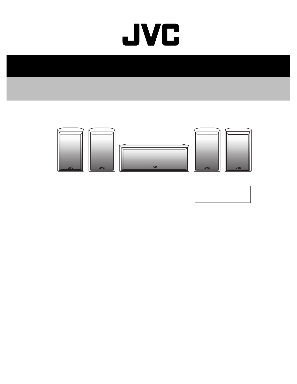
SATTELITE SPEAKER SYSTEM
SX-A305
SX-A305F
SX-A305F
SX-A305C
SX-A305F
Area Suffix
E ------- Continental Europe
SX-A305F
TABLE OF CONTENTS
1 PRECAUTION. . . . . . . . . . . . . . . . . . . . . . . . . . . . . . . . . . . . . . . . . . . . . . . . . . . . . . . . . . . . . . . . . . . . . . . . . 1-3
2 SPECIFIC SERVICE INSTRUCTIONS. . . . . . . . . . . . . . . . . . . . . . . . . . . . . . . . . . . . . . . . . . . . . . . . . . . . . . 1-4
3 DISASSEMBLY . . . . . . . . . . . . . . . . . . . . . . . . . . . . . . . . . . . . . . . . . . . . . . . . . . . . . . . . . . . . . . . . . . . . . . . 1-5
4 ADJUSTMENT . . . . . . . . . . . . . . . . . . . . . . . . . . . . . . . . . . . . . . . . . . . . . . . . . . . . . . . . . . . . . . . . . . . . . . . 1-11
5 TROUBLESHOOTING . . . . . . . . . . . . . . . . . . . . . . . . . . . . . . . . . . . . . . . . . . . . . . . . . . . . . . . . . . . . . . . . . 1-11
COPYRIGHT © 2003 VICTOR COMPANY OF JAPAN, LIMITED
No.MB091
2003/11
Page 2
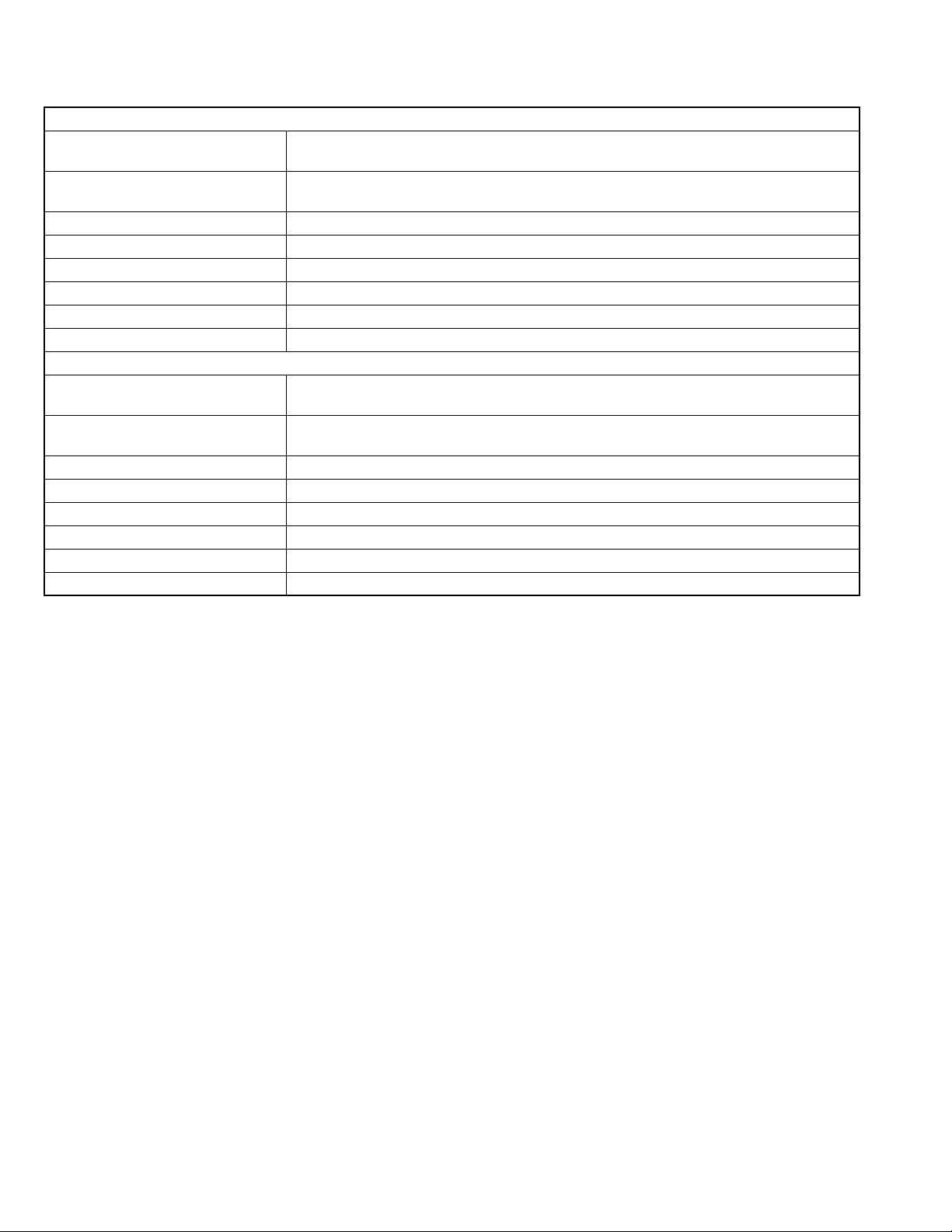
SPECIFICATION
SX-A305F
Type 2-Way Bass-reflex type
Magnetically Shielded Type
Speaker 12.0 cm cone × 1
2.0 cm dome × 1
Power Handling Capacity 100W
Impedance 8 Ω
Frequency Range 60 Hz ~ 50 000 Hz
Sound Pressure Level 85.5 dB/W
Dimensions (W × H × D) 153 mm × 251 mm × 189.5 mm
Mass 3.2 kg each
Type 2-Way 3-Speakers
Bass-reflex type
Speaker 10.0 cm cone × 2
2.0 cm dome × 1
Power Handling Capacity 100W
Impedance 8 Ω
Frequency Range 60 Hz ~ 50 000 Hz
Sound Pressure Level 86.5 dB/W
Dimensions (W × H × D) 350 mm × 144.5 mm × 189.5 mm
Mass 3.8 kg
·m
SX-A305C
·m
1-2 (No.MB091)
Page 3
SECTION 1
PRECAUTION
1.1 Safety Precautions
(1) This design of th is product contains special hardw are and
many circuits and components specially for safety purposes. For continued protection, no changes should be made
to the original design unless authorized in writing by the
manufacturer. Replacement parts must be identical to
those used in the original circuits. Services should be performed by qualified personnel only.
(2) Alterations of the design or circuitry of the product should
not be made. Any design alterations of the product should
not be made. Any design alterations or additions will void
the manufacturers warranty and will further relieve the
manufacture of responsibility for personal injury or property
damage resulting therefrom.
(3) Many electrical and mechanical parts in the products have
special safety-related characteristics. These characteristics are often not evident from visual inspection nor can the
protection afforded by them necessarily be obtained by using replacement components rated for higher voltage, wattage, etc. Replacement parts which have these special
safety characteristics are identified in the Parts List of Service Manual. Electrical components having such features
are identified by shading on the schematics and by ( ) on
the Parts List in the Service Manual. The use of a substitute
replacement which does not have the same safety characteristics as the recommended replacement parts shown in
the Parts List of Service Manual may create shock, fire, or
other hazards.
(4) The leads in the products are routed and dressed with ties,
clamps, tubings, barriers and the like to be separated from
live parts, high temperature parts, moving parts and/or
sharp edges for the prevention of electric shock and fire
hazard. When service is required, the original lead routing
and dress should be observed, and it should be confirmed
that they have been returned to normal, after reassembling.
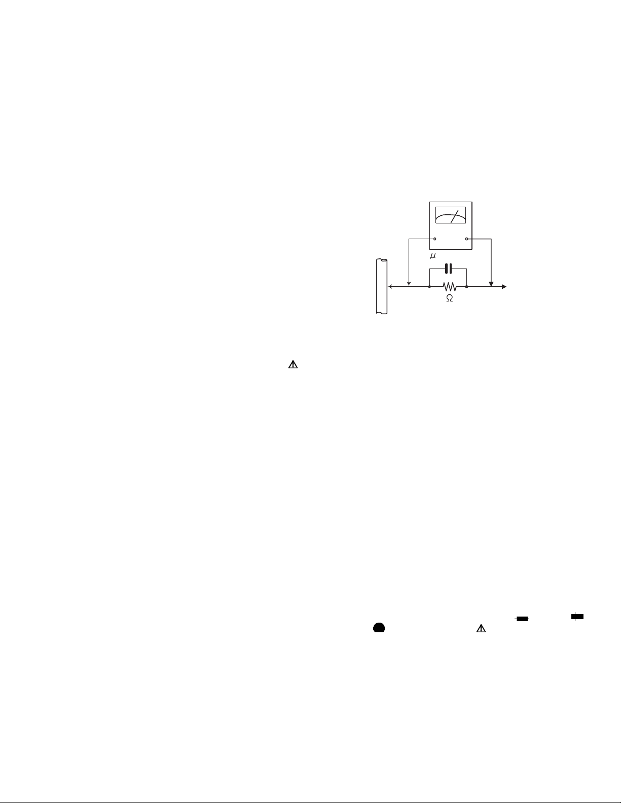
(5) Leakage shock hazard testing
After reassembling the product, always perform an isolation check on the exposed metal parts of the product (antenna terminals, knobs, metal cabinet, screw heads,
headphone jack, control shafts, etc.) to be sure the product
is safe to operate without danger of electrical shock.Do not
use a line isolation transformer during this check.
• Plug the AC line cord directly into the AC outlet. Using a
"Leakage Current Tester", measure the leakage current
from each exposed metal parts of the cabinet, particularly any exposed metal part having a return path to the
chassis, to a known good earth ground. Any leakage current must not exceed 0.5mA AC (r.m.s.).
• Alternate check method
Plug the AC line cord directly into the AC outlet. Use an
AC voltmeter having, 1,000Ω per volt or more sensitivity
in the following manner. Connect a 1,500Ω 10W resistor
paralleled by a 0.15µF AC-type capacitor between an exposed metal part and a known good earth ground.
Measure the AC voltage across the resistor with the AC
voltmeter.
Move the resistor connection to each exposed metal
part, particularly any exposed metal part having a return
path to the chassis, and measure the AC voltage across
the resistor. Now, reverse the plug in the AC outlet and
repeat each measurement. Voltage measured any must
not exceed 0.75 V AC (r.m.s.). This corresponds to 0.5
mA AC (r.m.s.).
AC VOLTMETER
(Having 1000
ohms/volts,
or more sensitivity)
0.15 F AC TYPE
Place this
probe on
1500 10W
Good earth ground
1.2 Warning
(1) This equipment has been designed and manufactured to
meet international safety standards.
(2) It is the legal resp onsibility of the repairer to ensure that
these safety standards are maintained.
(3) Repairs must be made in accordance with the relevant
safety standards.
(4) It is essential that safety critical compone nts are replaced
by approved parts.
(5) If mains voltage selector is provided, check setting for local
voltage.
1.3 Caution Burrs formed during molding may be left over on some parts
of the chassis.
Therefore, pay attention to such burrs in the case of preforming repair of this system.
1.4 Critical parts for safety
In regard with component parts appearing on the silk-screen
printed side (parts side) of the PWB diagrams, the parts that are
printed over with black such as the resistor ( ), diode ( )
and ICP ( ) or identified by the " " mark nearby are critical
for safety. When replacing them, be sure to use the parts of the
same type and rating as specified by the manufacturer.
(This regulation dose not Except the J and C version)
each exposed
metal part.
(No.MB091)1-3
Page 4

SECTION 2
SPECIFIC SERVICE INSTRUCTIONS
This service manual does not describe SPECIFIC SERVICE INSTRUCTIONS.
1-4 (No.MB091)
Page 5

3.1 Front speaker
A
A
3.1.1 Removing the front cover
(See Fig.1)
(1) Release the four joints a and remove the front cover.
SECTION 3
DISASSEMBLY
Front cover
3.1.2 Removing the A speaker
(See Fig.2 ~ 4)
(1) Remove the four screws A on the front panel.
(2) Remove the two screws B on the front panel.
(3) Disconnect the yellow wire and black wire from terminals
on the B speaker respectively.
(4) Remove the four screws C attaching the A speaker on the
front panel.
Front panel
speaker
A
A
Joint a
Joint a
A
A
speaker
terminal
Joint a
Joint a
Fig.1
speaker
B
B
speaker
Fig.2
B
A
A
Fig.3
speaker
CC
Front panel
Fig.4
(No.MB091)1-5
Page 6

3.1.3 Removing the B speaker
(See Fig.5 , 6)
• Prior to performing the following procedure, remove the front
cover and the front panel.
(1) Remove the four screws D attaching the B speaker.
(2) Disconnect the red wire and black wire from the terminal on
the B speaker.
B
DD
speaker
Fig.5
B
speaker
Fig.6
B
speaker
terminal
1-6 (No.MB091)
Page 7

3.1.4 Removing the D section
(See Fig.7 ~ 9)
(1) Remove the four screws E attaching the D cover.
(2) If necessary, unsolder the two terminals and bonding.
EE
D section
Fig.7
Bonding
Bonding
D section
Bonding
Solding
Fig.8
Solding
Bonding
terminal
Fig.9
(No.MB091)1-7
Page 8

3.2 Center speaker
3.2.1 Removing the front cover
(See Fig.10)
(1) Release the four joints b and remove the front cover.
Joint b
Front cover
Joint b
3.2.2 Removing the A speaker
(See Fig.11 ~ 13)
(1) Remove the four screws F on the front panel.
(2) Remove the four screws G on the front panel.
(3) Disconnect the yellow wire and black wire fro m terminals
on the A speaker respectively.
(4) Remove the four screws H attach ing the A sp eaker on the
front panel.
Joint b
Fig.10
speaker
A
FGG
Front panel
Joint b
F
FGGF
speaker
B
Front panel
Fig.11
B
speaker
1-8 (No.MB091)
A
speaker
A
speaker
terminal
Fig.12
H
H
Fig.13
A
speaker
Page 9

3.2.3 Removing the B speaker
(See Fig.14 , 15)
• Prior to performing the following procedure, remove the front
cover and the front panel.
(1) Remove the eight screws J attaching the B speaker.
(2) Disconnect the black wire from the two terminals on the B
speaker.
(3) Disconnect the red wire and black wire from the terminal on
the B speaker.
JJ
speaker
B
JJ
Fig.14
speaker
B
B
speaker
terminal
Black
Red
Fig.15
Black
B
Black
speaker
terminal
(No.MB091)1-9
Page 10

3.2.4 Removing the D section
(See Fig.16 ~ 18)
(1) Remove the four screws K attaching the D cover.
(2) If necessary, unsolder the two terminals and bonding.
K
D section
K
Fig.16
Bonding
D section
C section
Solding
Fig.17
Bonding
Solding
Fig.18
1-10 (No.MB091)
Page 11

SECTION 4
ADJUSTMENT
This service manual does not describe ADJUSTMENT.
SECTION 5
TROUBLESHOOTING
This service manual does not describe TROUBLESHOOTING.
(No.MB091)1-11
Page 12

VICTOR COMPANY OF JAPAN, LIMITED
AV & MULTIMEDIA COMPANY AUDIO/VIDEO SYSTEMS CATEGORY 10-1,1chome,Ohwatari-machi,Maebashi-city,371-8543,Japan
(No.MB091)
Printed in Japan
WPC
 Loading...